

Page 1
3
iS
Intelligent Small Site Supervisor
User’s Guide
Page 2

Page 3

Intelligent Small Site Supervisor
The information contained in this document is the property of MULTITEL INC.
Except as specifically authorized in writing by MULTITEL INC., the holder of this
document shall:
1. Keep all information contained herein confidential and shall protect same in whole
or in part from disclosure and dissemination to all third parties and;
2. Use the same for operating and maintenance purposes only.
2003 MULTITEL Inc.
Printed in Canada , 2003-06
iS3
Version 1.4
User’s Guide
PROPRIETARY INFORMATION
Page 4

iS
Table of Contents
TABLE OF CONTENTS..................................................................................................................... 2
Tables .............................................................................................................................................. 5
Figures............................................................................................................................................. 5
ABOUT…....................................................................................................................................... 7
CERTIFICATION INFORMATION .................................................................................................... 7
LIMITED WARRANTY POLICY ON MULTITEL HARDWARE ......................................................... 8
GENERAL INFORMATION............................................................................................................... 9
PURPOSE .......................................................................................................................................... 9
APPLICATION ................................................................................................................................... 9
CHAPTER 1 .............................................................................................................................. 11
3
– intelligent Small Site Supervisor - User’s Guide
INTRODUCING THE IS3................................................................................................................. 11
GETTING STARTED ........................................................................................................................ 11
PPP Connection Procedure (Windows ’98) .................................................................................. 12
PPP Connection Procedure (Windows 2000)................................................................................ 13
Baud Rate Detection Procedure..................................................................................................... 15
Changing the PPP Connection Baud Rate (Windows 2000)........................................................ 16
Changing the PPP Connection Baud Rate (Windows ‘98)........................................................... 16
CHAPTER 2 .............................................................................................................................. 17
CHANNELS .................................................................................................................................... 17
DIFFERENT TYPES OF CHANNELS .................................................................................................. 17
Real Channels................................................................................................................................ 18
Derived Channels .......................................................................................................................... 18
Analog Channels ........................................................................................................................... 18
Binary Channels ............................................................................................................................ 19
CHANNEL RETURNED VALUES ...................................................................................................... 20
CATEGORIES .................................................................................................................................. 20
ALARMS AND ALARM PRIORITY.................................................................................................... 22
CHAPTER 3 .............................................................................................................................. 23
DETAILED CHANNEL DESCRIPTION............................................................................................ 23
CHANNELS ..................................................................................................................................... 23
CHANNEL CONFIGURATION........................................................................................................... 23
BINARY CHANNEL CHARACTERISTICS .......................................................................................... 23
Binary Channel Returned Values ..................................................................................................23
Common Binary Channel Parameters ........................................................................................... 24
2
Page 5

iS
Binary Channel Occurrence Counter............................................................................................. 24
ANALOG CHANNELS CHARACTERISTICS ....................................................................................... 25
Analog Channel Returned Values ................................................................................................. 25
Common Analog Channel Parameters .......................................................................................... 25
CHANNEL DESCRIPTION – BY TYPE............................................................................................ 26
REAL CHANNELS ........................................................................................................................... 26
Binary Input Channels................................................................................................................... 26
Binary Output Channels ................................................................................................................ 28
Analog Input Channels.................................................................................................................. 29
Analog Output Channels ............................................................................................................... 30
Binary LED Channels ................................................................................................................... 30
DERIVED CHANNELS ..................................................................................................................... 31
Binary Threshold Channels ........................................................................................................... 31
Binary Delay Channels.................................................................................................................. 34
Binary Equation Channels............................................................................................................. 35
Binary Manual Channels ............................................................................................................... 36
Analog Hold Channels .................................................................................................................. 37
Analog “Binary Occurrence Counter” Channels........................................................................... 39
Analog Computation Channels...................................................................................................... 40
Analog Polynomial Channels........................................................................................................ 41
Analog Manual Channels .............................................................................................................. 42
Analog Binary Count Channels..................................................................................................... 42
SYSTEM CHANNELS ....................................................................................................................... 43
Introduction to System Channels................................................................................................... 43
System Channels Specifics............................................................................................................ 43
System Channels List .................................................................................................................... 43
Using System Channels................................................................................................................. 44
USERS AND USER CHANNELS ........................................................................................................ 44
User Channels................................................................................................................................ 44
User Definition .............................................................................................................................. 45
Maximum Number of Users.......................................................................................................... 45
3
– intelligent Small Site Supervisor - User’s Guide
CHAPTER 4 .............................................................................................................................. 47
MESSAGING .................................................................................................................................. 47
BINARY AUTONOMOUS MESSAGES ............................................................................................... 47
SCHEDULES.................................................................................................................................... 48
MESSAGE TEMPLATES ................................................................................................................... 48
USING AUTONOMOUS MESSAGES ................................................................................................. 50
CHAPTER 5 .............................................................................................................................. 51
DATA LOGGING ............................................................................................................................ 51
BINARY DATA LOGGING (HISTORY FILE) ..................................................................................... 51
Using Binary Data Logging Files.................................................................................................. 51
History File Content ...................................................................................................................... 51
History File Reset.......................................................................................................................... 52
ANALOG DATA LOGGING .............................................................................................................. 53
Periodic File .................................................................................................................................. 53
3
Page 6

iS
Detailed File .................................................................................................................................. 53
Histogram File............................................................................................................................... 54
CHAPTER 6 .............................................................................................................................. 55
INTERFACES TO THE IS3............................................................................................................... 55
ACCESS LEVELS............................................................................................................................. 55
Using Access Levels...................................................................................................................... 55
WEB INTERFACE ............................................................................................................................ 55
Using the Web Interface................................................................................................................ 57
FTP INTERFACE............................................................................................................................. 61
Using the FTP Interface................................................................................................................. 61
SNMP INTERFACE......................................................................................................................... 63
CHAPTER 7 .............................................................................................................................. 65
PASS-THROUGH............................................................................................................................ 65
PASS-THROUGH DEFINITION ......................................................................................................... 65
HOW DOES PASS-THROUGH WORK............................................................................................... 66
SPECIFIC PASS-THROUGH PARAMETERS ....................................................................................... 66
CONFIGURING PASS-THROUGH ..................................................................................................... 67
Using the Serial Ports Involved in Pass-through........................................................................... 67
3
– intelligent Small Site Supervisor - User’s Guide
CHAPTER 8 .............................................................................................................................. 69
CONFIGURING THE IS3................................................................................................................. 69
CHAPTER 9 .............................................................................................................................. 71
INSTALLING THE IS3..................................................................................................................... 71
CHAPTER 10 ............................................................................................................................ 73
MAINTENANCE ............................................................................................................................. 73
BACK-UP BATTERY........................................................................................................................ 73
CALIBRATION ................................................................................................................................75
TROUBLESHOOTING....................................................................................................................... 75
Troubleshooting with communication........................................................................................... 75
Troubleshooting without communication...................................................................................... 79
CHAPTER 11 ............................................................................................................................ 81
CONTACTING MULTITEL.......................................................................................................... 81
CHAPTER 12 ............................................................................................................................ 83
4
Page 7

iS
APPENDIX A.................................................................................................................................. 83
CHAPTER 13 ............................................................................................................................ 85
INDEX ............................................................................................................................................ 85
Tables
Table 1 - Returned values........................................................................................................................... 20
Table 2 - Returned values for analog channels .......................................................................................... 25
Table 3 - Access levels specifics ................................................................................................................ 45
Table 4 - CSV file imported into Excel...................................................................................................... 52
Table 5 - Binary channel truth table ........................................................................................................... 83
Figures
Figure 1 - iS
Figure 2 - Front Panel................................................................................................................................. 12
Figure 3 - Front Panel................................................................................................................................. 13
Figure 4 - Channel matrix .......................................................................................................................... 17
Figure 5 - Web page and categories ........................................................................................................... 21
Figure 6 - Dry contact binary channel schematics ..................................................................................... 26
Figure 7 - Level binary channel schematics ............................................................................................... 27
Figure 8 - Binary threshold activation schematics ..................................................................................... 32
Figure 9 - Binary threshold deactivation schematics.................................................................................. 33
Figure 10 - Analog hold channel schematics ............................................................................................. 38
Figure 11 - Web Interface .......................................................................................................................... 56
Figure 12 - Alarms Page............................................................................................................................. 58
Figure 13 - Categories Menu...................................................................................................................... 58
Figure 14 - System Page............................................................................................................................. 59
Figure 15 - File Download Page................................................................................................................. 59
Figure 16 - Calibration Page ...................................................................................................................... 60
Figure 17 - Test Mode................................................................................................................................ 61
Figure 18 - Pass-through schematics.......................................................................................................... 65
3
functional overview ............................................................................................................. 10
3
– intelligent Small Site Supervisor - User’s Guide
5
Page 8

Page 9

iS
3
– intelligent Small Site Supervisor - User’s Guide
About…
Certification Information
RESIDENTIAL EQUIPMENT
CLASS B DIGITAL DEVICE
INFORMATION TO USER
This device complies with Part 15 of the FCC Rules. Operation is subject to the
following two conditions: (1) This device may not cause harmful interference, and
(2) This device must accept any interference received, including interference that
may cause undesired operation.
This equipment has been tested and found to comply with the limits for Class B
Digital Device, pursuant to Part 15 of the FCC Rules. These limits are designed to
provide reasonable protection against harmful interference in a residential
installation. This equipment generates, uses, and can radiate radio frequency energy
and, if not installed and used in accordance with the instructions, may cause harmful
interference to radio communications. However, there is no guarantee that
interference will not occur in a particular installation. If this equipment does cause
harmful interference to radio or television reception, which can be determined by
turning the equipment off and on, the user is encouraged to try to correct the
interference by one or more of the following measures.
• Reorient or relocate the receiving antenna.
• Increase the separation between the equipment and receiver.
• Connect the equipment into an outlet on a circuit different from that to which the
receiver is connected.
• Consult the dealer or an experienced radio/TV technician for help.
Any changes or modifications not expressly approved by the party responsible for
compliance could void the user’s authority to operate the equipment.
7
Page 10

iS
Limited Warranty Policy on Multitel Hardware
MULTITEL represents, warrants and covenants to Buyer that, for a period of twenty-four
months after shipping date of such Product, the Product when installed and used in accordance
with specifications described in user manuals, technical materials and related writings
published by MULTITEL with respect to such Product, shall be free from defects in materials
and workmanship.
During the warranty period, MULTITEL or its designated service representative
shall repair, or at its option, replace any Product that is confirmed to be defective
by MULTITEL. Product repaired under warranty shall be warranted for six (6)
months or for the non-expired portion of the warranty applying to the Product,
whichever is longer. Buyer shall promptly notify MULTITEL of any Product’s
defect during the warranty period.
This warranty shall be null and void if the Product has been damaged by accident,
misuse or misapplication or has been modified or altered by Buyer without
MULTITEL’s express written acceptance of Buyer’s modifications for warranty
purposes.
Upgrades, new releases and product modifications requested by the customer are
not covered by this guarantee.
Administrative charges will be billed for any unit returned on which no defect is found.
Notwithstanding the foregoing, MULTITEL’s liability for breach of any warranty
or covenant set forth in this document shall be limited as follows:
1. The duty to indemnify provided above may be asserted only by MULTITEL;
2. MULTITEL’s sole obligations arising due to a breach of the Product Performance
Warranty provided above shall be to:
cause the Product to perform substantially in accordance with Product specifications described
in the user manuals, technical materials and related writings published by
MULTITEL with respect to the Product, or if that is not commercially practical, then
reimburse the Product price charged to Buyer, plus the cost of shipment of such Product paid
by Buyer, if any;
3. THE LIABILITY OF MULTITEL FOR DAMAGES UNDER THIS DOCUMENT,
OTHER THAN FOR PERSONAL INJURY, RELATING TO ANY ALLEGEDLY
EFFECTIVE PRODUCT, SHALL, UNDER ANY LEGAL OR EQUITABLE
THEORY, BE LIMITED TO THE ACTUAL PRICE PAID BY BUYER FOR SUCH
PRODUCT AND SHALL IN NO EVENT INCLUDE INCIDENTAL,
CONSEQUENTIAL OR SPECIAL DAMAGES OF ANY KIND (EVEN IF
MULTITEL IS NOTIFIED OF THE POSSIBILITY OF SUCH DAMAGES.
3
– intelligent Small Site Supervisor - User’s Guide
8
Page 11

iS
4. THERE ARE NO WARRANTIES OTHER THAN THOSE WHICH APPEAR ON
THIS DOCUMENT AND IMPLIED WARRANTIES OF FITNESS FOR A
PARTICULAR PURPOSE OR OF MERCHANTABILITY ARE HEREBY
DISCLAIMED.
NOTE:
Some states or provinces do not allow the exclusion or limitation of
consequential damages, so the above limitation or exclusion may not apply to
you.
General Information
Purpose
This document is intended to present the functions, applications and basic concepts of
3
the iS
. An Installation manual is also provided with this product.
3
– intelligent Small Site Supervisor - User’s Guide
Application
The iS3 is a very versatile monitoring and control unit tailored for space-sensitive
applications such as cabinets.
• Up to 28 real channels without expansion board and 44 with expansion board can be
configured to detect harmful conditions, take measurements, and control local
equipment;
• An almost unlimited number of derived channels can also be configured to process
measurements or create complex alarm messages;
• Data logging files record information about your site, helping to trend and analyze
site behavior;
• An easy-to-use Web browser-based interface that makes getting information a breeze.
• Support of SNMP with full HP OpenView integration kit.
• Pass-through function, offering an embedded 2 port terminal server.
9
Page 12
iS
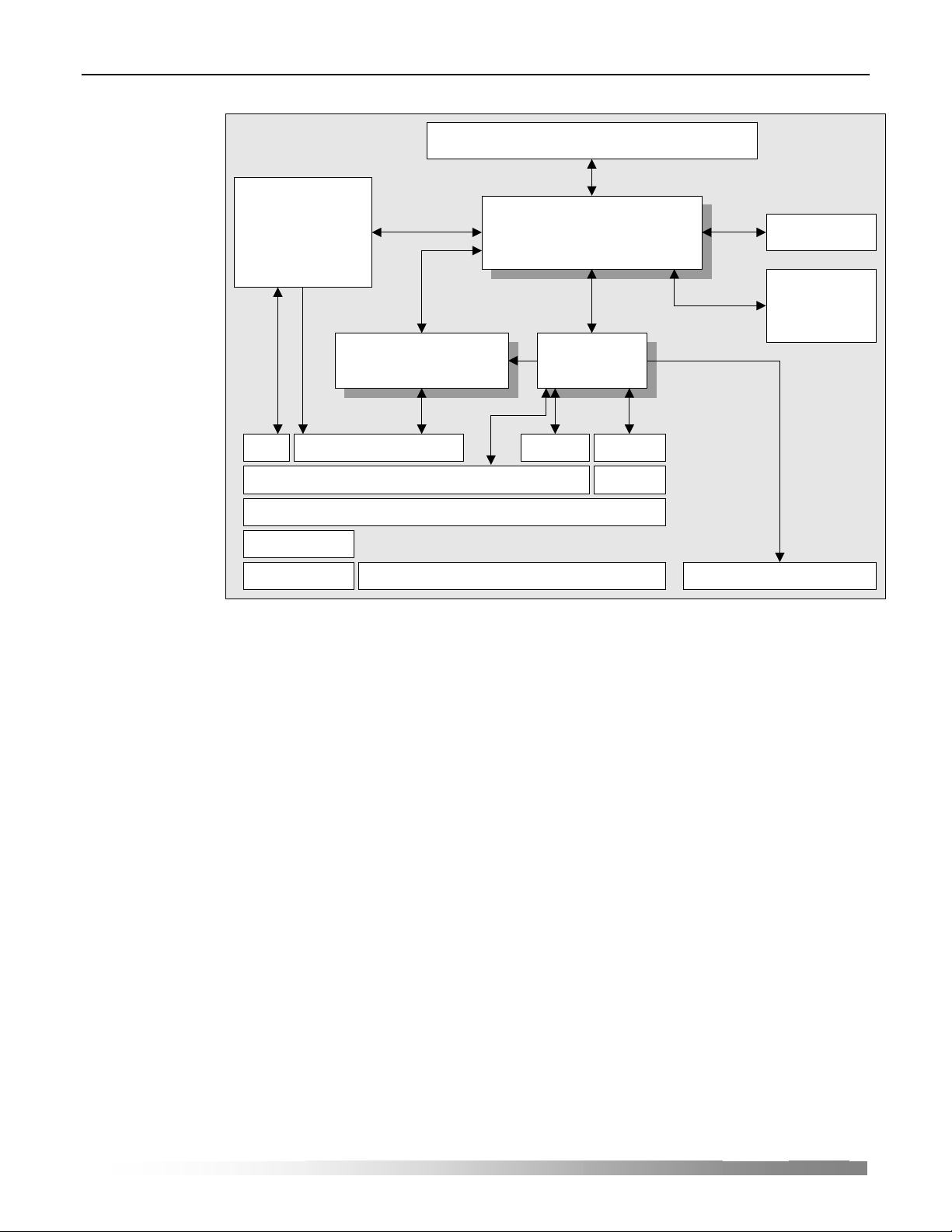
File System
------------
Configuration files
Firmware files
------------
Data Logging files
Data Acquisition &
Channel Engine Process
3
– intelligent Small Site Supervisor - User’s Guide
I/O Interfaces
System
Channels
Real & Derived
Channels
Interface
Alamrs &
Messages
FTP HTTP SMTP SNMP
TCP UDP
IP
PPP
Serial & modem Serial & modem
Ethernet
Figure 1 - iS3 functional overview
3
Since the iS
is targeted for telecommunication applications, its internal power supply
will accept the standard –48 VDC or +24 VDC, depending on the model.
10
Page 13

iS
CHAPTER 1
Introducing the iS3
3
– intelligent Small Site Supervisor - User’s Guide
The iS3 has all the traditional features of an RMU (remote monitoring unit), despite
its small size and low power consumption. In fact, the iS
3
possesses more features
than most RMU, including extended connectivity provided by a standard Ethernet
port and an optional internal high-speed modem.
Data acquisition is done using simple binary or more complex analog inputs. Using
the latter type, measurement of voltage, current, temperature, humidity, and other
parameters is done using a 12-bit analog to digital converter.
3
The iS
offers an embedded Web server, providing a very easy means to view realtime data, download data logging files, calibrate the unit data acquisition channels,
etc.
The iS
3
also comes with an SNMP agent, SMTP support to send e-mails, an FTP
server to easily upload and download configuration and data logging files. A passthrough function has been added in order to provide terminal server capability. This
means you can connect legacy devices to your IP network through the iS
Users and their access to the iS
3
can also be managed through the very unit. You can
3
.
define a high number of users, each having one of 3 possible user access levels,
allowing the management of users and the type of action they can perform while
using the iS
3
.
Using the LAMBDA (Logical And Mathematical Built-in Data Analyzer) engine, the
3
provides real time data processing. A set of derived channels, through which you
iS
configure unit behavior, allows you to build powerful custom applications that
further process and analyze acquired data.
Getting Started
The first and most important step once the equipment has been installed, plugged
and all proper connections have been made is to establish direct communication
between your PC and the iS
these units: the Ethernet and the PPP (point to point protocol).
Once the iS
just turning the unit on. The unit is delivered with a default IP address which does not
guarantee immediate communication between the unit and your PC because it is not
necessarily compatible with your network. Therefore, to have these two units
communicating through the same language, you will have to carry out, at least and
depending on your operating system, one of the following two procedures.
3
. There are two main protocols to communicate with
3
is installed, setting it ready to operate for the first time takes more than
11
Page 14

iS
PPP Connection Procedure (Windows ’98)
To establish communication with the iS3 using Windows ’98:
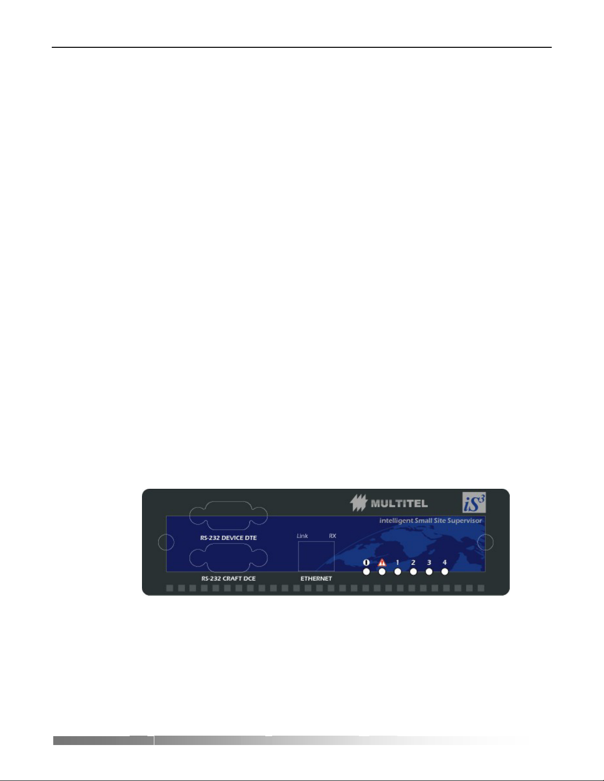
5. Connect a DB9 serial cable from the RS-232 CRAFT DCE port on the iS
panel to your PC.
Figure 2 - Front Panel
6. Determine the iS3 baud rate, see Baud Rate Detection Procedure.
7. Add a standard modem.
a) Follow the sequence: Start + Settings + Control Panel.
3
– intelligent Small Site Supervisor - User’s Guide
3
front
b) Click on Phone and Modem Options.
c) In the Modems tab, verify there is no Standard 33600 bps Modem already
installed. If you already have such modem installed, close this window and
continue with step 8.
d) Click on Add.
e) Check the Don’t detect my modem; I will select it from a list box.
f) Click on Next.
g) In the Manufacturers list, choose Standard Modem Types.
h) In the Models list, choose Standard 33600 bps Modem.
i) Click on Next.
j) Choose the port you want to use (Com 1, Com 2…) and click on Next.
k) Click on Finish.
l) In the Control Panel, double-click on Phone and Modem Options.
m) In the Modems tab, select Standard 33600 bps Modem and click on
Properties.
n) In the Maximum Port Speed section, choose the baud rate that corresponds to
the iS
3
(you must have already determined it on step 6).
12
o) Click on OK, then on Close.
8. Create a PPP Connection.
a) In your desktop, click on My Computer.
b) Click on Dial-up Networking + New Connection.
3
c) Name your connection iS
Direct Connection.
Page 15
iS
d) Select Standard 33600 bps Modem.
e) Click on Configure.
f) Click on OK + Next.
g) Type in the telephone number “555” + Next + Finish.
h) Right click on your connection and select Properties.
i) Uncheck the Use area code box.
j) Select the Network Management tab.
k) Uncheck all the available boxes except TCP/IP.
l) Select the Running Script tab.
m) Click on Run and search for the script provided by Multitel (Multitel iS3
PPP.scp).
3
– intelligent Small Site Supervisor - User’s Guide
n) Click on OK.
9. You are now ready to launch the connection; click on iS
3
Direct Connection +
Connect.
10. If the connection is not successful, revise the connection procedure and the cables.
11. After the connection has been established, click on Start + Run.
12. In the Open text field, type “winipcfg” and then click on OK.
13. Take note of the IP address.
14. Open you Internet browser and type the IP address that you jotted down minus
ONE. As an example, if you found the following IP address: 192.68.10.11, the iS
IP address will be 192.68.10.10.
At this point you should see the iS
3
web page.
PPP Connection Procedure (Windows 2000)
To establish communication with the iS3 using Windows 2000:
1. Connect a DB9 serial cable from the RS-232 CRAFT DCE port on the iS
panel to your PC.
3
front
3
Figure 3 - Front Panel
2. Determine the iS3 baud rate, see Baud Rate Detection Procedure.
3. Add a standard modem.
a) Follow the sequence: Start + Settings + Control Panel.
b) Click on Phone and Modem Options.
13
Page 16

iS
c) In the Modems tab, verify there is no Standard 33600 bps Modem already
installed. If you already have such modem installed, close this window and
continue with step 8.
d) Click on Add.
e) Check the Don’t detect my modem; I will select it from a list box and click
on Next.
f) In the Manufacturers list, choose Standard Modem Types.
g) In the Models list, choose Standard 33600 bps Modem and click on Next.
h) Choose the port you want to use (Com 1, Com 2…) and click on Next.
i) Click on Finish.
j) In the Control Panel, double-click on Phone and Modem Options.
k) In the Modems tab, select Standard 33600 bps Modem and click on
Properties.
3
– intelligent Small Site Supervisor - User’s Guide
l) In the Maximum Port Speed section, choose the baud rate that corresponds to
the iS
3
(you must have already determined it on step 0).
m) Click on OK, then on Close.
4. Create a PPP connection.
a) Click on Start + Settings and double click on Network and Dial-up
Connections.
b) Double click on Make New Connection and click on Next.
c) Choose Dial-up to the Internet and click on Next.
d) Choose I want to set up my Internet connection manually, or I want to
connect through a local area network (LAN), then click on Next.
e) Choose I connect through a telephone line and a modem, then click on
Next.
f) If you have only one modem installed, do the next step; if not, choose the
Standard 33600 bps Modem that you already created and click on Next.
g) Type the telephone number “555”.
h) Uncheck the Use area code and dialing rules option, then click on Next.
i) Do not enter any password, click on Next.
j) Click Yes on the warning.
14
k) Name your PPP connection iS3 Direct Connection, then click on Next.
l) Answer No to the question: Do you want to set up an Internet mail account
now? Then, click on Next.
m) Do not check the To connect to the Internet immediately, select this box
and click Finish box. Click on Finish.
3
n) In the Network and Dial-up Connections, right-click on iS
Direct
Connection and select Properties.
Page 17

iS
o) Select the Security tab.
p) Select Run script.
q) Click on Browse and search for the script provided by Multitel (Multitel iS3
PPP.scp).
r) Select the Networking tab and click on Settings.
s) Uncheck the Software Compression option and click on OK.
t) Select Internet Protocol (TCP/IP)
u) Click on Properties + Advanced.
v) Uncheck the Use default gateway on remote network and click OK in the
following three dialog boxes.
w) Click on Start + Settings + Control Panel + Internet Options.
x) Select the Connections tab.
y) In the Dial-up and Virtual Private Network settings set up the default
connection, which you must have previously jotted down, and select the Never
dial a connection, dial whenever option. Click on OK to exit.
5. Now you are ready to establish the connection, to do that: click on Start + Settings
+ Network and Dial-up Connections + iS3 Direct Connection and then on Dial.
6. If the connection is not successful, check the connection procedure and the cables.
7. After the connection has been established, double-click on it, select the Details tab
to find the server IP address.
8. Launch your Internet browser and type the server IP address, press Enter. You
must access the iS
3
web page.
Baud Rate Detection Procedure
The iS3 baud rate is generally 115200 bps. If you have access to the iS3 configuration
files, use the iS
DCE port baud rate. The following procedure is useful in the case you don’t have
access to the configuration files and you need the baud rate to establish the
connection.
1. Make sure there are no open applications in your PC.
2. Launch the HyperTerminal application.
3
Configuration Tool software to find out the iS3 RS-232 CRAFT
3
– intelligent Small Site Supervisor - User’s Guide
a) Click on Start + Run.
b) In the Open text field, type “Hypertrm.exe” and click on OK.
3. Name your connection, ex.: iS
4. In the Connect using tab, choose the PC serial port you want to use to
communicate with the iS
3
.
3
(usually Com 1 or Com 2) and click on OK.
5. In the Port Parameters window, change the bits per second to 115200 and click on
OK.
6. Click on the main window to select it.
7. On your keyboard, press Enter four times. If you see the equipment identification
on the display, it means you have found the good baud rate. Then, the procedure is
finished.
8. If not, click on the Call menu, then select Disconnect.
15
Page 18

iS
9. Click on the File menu, then Properties.
10. In the Connect using list of the Connect to tab, select the right port and click on
Configure.
11. Change the Bits per second to the immediate lower available value and click on
OK.
12. In the Port Parameters window, click on OK.
13. Click on the main window to select it.
14. On your keyboard, press Enter four times. If you see the equipment identification
on the display, it means you have found the good baud rate.
15. Take note of the baud rate and close the window.
NOTE:
You should continue to try this procedure with the immediate lower value until you find the
correct baud rate.
Changing the PPP Connection Baud Rate (Windows 2000)
To change the PPP connection baud rate for Windows 2000:
1. Click Start + Settings + Network and Dial-up Connections.
2. In the Network and Dial-up Connections window, right-click on your connection
and select Properties.
3. In the General tab, click on Configure.
4. In the Maximum speed (bps) list, choose the desired baud rate and click on OK.
5. In the Properties windows, click on OK.
6. Click on Start + Settings + Control Panel.
7. In the Control Panel window, double-click on Phone and Modem Options.
8. Click on the Modems tab.
9. Double-click on the Modem standard 33600 bps.
10. Change the maximum speed to match the one previously set in the Network and
Dial-up Connections window and click on OK.
11. In the Phone and Modem Options window, click on OK.
Your connection is now ready to be used with the new baud rate.
Changing the PPP Connection Baud Rate (Windows ‘98)
To change the PPP connection baud rate for Windows ‘98:
1. On your desktop, click on My Computer.
2. Double-click on Dial-up Networking.
3. Right-click on your connection and select Properties.
4. In the General tab, click on Configure.
5. In the Maximum speed section, select the desired baud rate from the list and click
on OK.
6. In the Properties window, click on OK.
Your connection is now ready to be used with the new baud rate.
3
– intelligent Small Site Supervisor - User’s Guide
16
Page 19

iS
CHAPTER 2
Channels
Channels are a central concept to the iS3. Channels are used to retrieve information,
filter it, and raise alarms when any abnormal condition occurs.
For example, when connected to sensors, detectors or other measurement equipment,
channels can be used to monitor temperature in a telecommunications site, to detect
smoke, or to calculate the power dissipated by the load.
Different Types of Channels
Channels in the iS3 can be real or derived, analog or binary.
Channels are mainly differentiated by the type of information they produce (the
output of the channel). This means that a channel called a “binary channel” outputs a
binary value, whereas an “analog channel” outputs an analog value.
Moreover, channels are also differentiated by the source of the information they use.
Real channels are physically connected to equipment in the telecommunications site,
while derived channels use information from other channels; therefore, they are not
directly connected to a physical source in the site.
Channels MUST be
3
– intelligent Small Site Supervisor - User’s Guide
1. Analog OR Binary,
AND
2. Real OR Derived
REAL DERIVED
ANALOG
BINARY
Figure 4 - Channel matrix
Real analog channel Derived analog channel
Real binary channel Derived binary channel
17
Page 20

iS
Real Channels
Real channels are the most commonly known type of channels in remote monitoring
and site management equipment. A real channel in the iS
source, such as a detector activating a simple contact closure or an accessory
connected to a voltage source to be measured.
A real channel is associated with a connector at the back of the iS
detector or equipment is plugged in.
For example, a real channel can be connected to batteries to monitor their voltage, to
a motion detector to know when someone is in your site, or to a local generator set to
remotely or automatically control it in case of an AC power failure.
WARNING:
3
– intelligent Small Site Supervisor - User’s Guide
3
is connected to a physical
3
, where the meter,
Unused pins in the J1 connector must be left unconnected since they are not protected against
high voltage, e.g. –48VDC and permanent damage to the iS
3
may occur.
WARNING:
The binary output loads must preferably be resistive and must not exceed 0.5A @60VDC.
Inductive loads must use protection diodes to prevent inductive voltage spikes when loads are
de-energized.
Real channels may return one of two types of information: binary information or
analog information. That is, binary channels return only binary information, while
analog channels return only analog information.
Derived Channels
Derived channels are also known as computed channels. A derived channel is not
connected to a physical source in your telecommunications site. It generally uses data
from other channels in the iS
3
, real or derived, to create a series of combinations of
information to actually suit your needs.
Derived channels are used to process information from any other channel in your
device. For example, a derived channel can be used to detect when battery voltage
exceeds acceptable limits, to compute the power consumed by the load, or to
calculate the difference between battery and ambient temperature.
Depending on the type of channel analog or binary, derived channels may return two
types of information: binary information or analog information. That is, binary
channels return only binary information, while analog channels return only analog
information.
Analog Channels
Analog channels can be real or derived. These channels provide an analog value. Any
analog channel may be used as the input for any other channel whose input is an
analog value.
Real analog channels are often connected to some kind of transducer (e.g.
temperature probe) that produces an analog signal. These channels read, digitize and
18
Page 21

iS
return the value of the input signal. For example, an analog channel connected to a
temperature probe will produce a value that corresponds to the temperature reading
picked up by the probe.
Derived analog channels will be used to make calculations from any analog channel
value. For example, by adding the amperage from 3 real analog channels connected
to different loads in the telecommunications site, the derived analog channel
calculates the total current drawn.
There are several types of analog channels. To know more about real and derived
analog channels, read the Detailed Channel Description section.
Binary Channels
Binary channels can be real or derived. They are used to detect conditions, raise
warnings, or automate repetitive tasks. Any binary channel may be used as the input
for any other channel whose input is a binary value.
Real binary channels have two main states: ON or OFF. They are either connected to
a detector, such as a smoke detector, or to local equipment, such as a rectifier or LED
on the iS
When connected to a smoke detector, the binary input channel will turn on when
smoke is detected; when connected to a heat exchanger, the binary output channel
may turn on or off the heat exchanger.
Derived binary channels can be used in the automatic activation or deactivation of
warnings or equipment. They are usually utilized by other binary or analog channels,
and return a value – ON or OFF – that is used by other channels in the system.
For example, a derived binary channel can be used as a threshold to activate a high
voltage alarm. The binary channel monitors the battery voltage channel, and turns
ON when a certain level of voltage is reached. Derived binary channels can also be
used to delay the activation of a warning, to avoid false alarms.
There are several types of binary channels. To know more about real and derived
binary channels, read the Detailed Channel Description section.
3
front panel.
3
– intelligent Small Site Supervisor - User’s Guide
19
Page 22

iS
Channel Returned Values
Depending on their type, channels return different values. In short, as stated before,
analog channels return analog values and binary channels return simple ON/OFF
binary values. Channels can also return other values in some specific cases. For
example, if a channel appears in a system configuration but is configured as disabled,
it will return the special DIS value (disabled).
CHANNEL TYPE RETURNED VALUE COMMENT
ON Channel value is “Boolean” TRUE
OFF Channel value is “Boolean” FALSE
DIS Channel is disabled. Causes may be:
- Channel configured as disabled (in iS3
Binary
N/A Channel can’t return a value. Causes may be:
Note: For binary output channels, DIS and N/A will be interpreted as an OFF condition
NORMAL CONDITION
OVL+ Channel overflow (exceeds maximum value
OVL- Channel underflow (under minimum value
DIS Channel is disabled. Causes may be:
Analog
N/A Channel can’t return a value. Causes may be:
Note: OVL+ and OVL- conditions are correctly interpreted by binary threshold channels. Refer to
individual channel section for information on exceptions.
Configuration Tool)
- Too many sources of this channel returned
DIS
- Failure of channel (for real channels)
- At boot time (Initialization value)
permitted)
permitted)
- Channel configured as disabled (in iS3
Configuration Tool)
- Too many sources of this channel returned
DIS
- Failure or channel (for real channels
- At boot time (very short period)
- Invalid configuration
3
– intelligent Small Site Supervisor - User’s Guide
Categories
20
Table 1 - Returned values
The notion of category is tightly linked with the embedded Web interface that the iS3
system monitors offer you. Categories allow you to group channels, whatever their
types (real or derived, analog or binary) under user-defined categories. Here is an
example:
Page 23
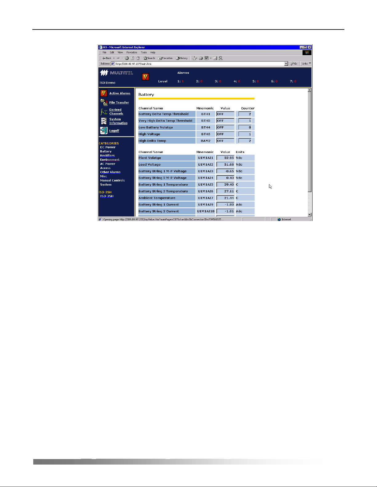
iS
3
– intelligent Small Site Supervisor - User’s Guide
Figure 5 - Web page
21
Page 24

iS
In the figure above, which is a typical page of the iS3 Web interface, the lower left
frame presents the user-defined categories. These categories were configured from
3
the iS
Configuration Tool software.
All category names are configurable, except for the “System” category. You can
associate any channel to any category. Also note that a channel may belong to more
than one category. Hence, a channel returning battery temperature may be in the
environment category as well as the battery category, allowing a quick comparison
between battery temperature and ambient temperature channels.
Alarms and Alarm Priority
The notion of alarm may have several meanings. A device alarm may be
• An alarm sent to a hardware alarm-gathering unit,
• An SNMP trap sent to some SNMP managers that present those traps as alarms,
• Proprietary messages sent to a NEM (Network Element Management) system,
• Etc.
In the iS
channel.
3
Configuration Tool, an alarm priority may be associated to every binary
3
– intelligent Small Site Supervisor - User’s Guide
NOTE:
The specific notion of alarm is internal to the iS3 system monitoring device.
This is not linked in any way with other “higher level” alarm concepts. The alarms
you define in the iS
by the iS
3
system monitors. To report alarms to a central surveillance system, then
3
Configuration Tool only appear in the user interface provided
you may use SNMP, SMTP, simple ASCII text or even simple binary outputs.
22
Page 25

iS
CHAPTER 3
Detailed Channel Description
The following chapter describes how the iS3 works. This will help you understand the
basic mechanism as well as make the relationships between the different functional
features.
Channels
As described in the previous chapter, channels are the basic source of information for
3
the iS
. They are used to collect, filter and process information to the surveillance
technicians.
Channel Configuration
Before being used, all channels must be configured. The Windows-based iS3
Configuration Tool software is used to easily enter necessary parameters to configure
each type of channel. Even if the iS
use, it is mandatory to understand the concept of each type of channel. The following
sections will describe the type of channels supported, their use and finally provide
details relative to the channel characteristics.
It is also important to mention that each channel type is fully described by its
parameters and associated values.
3
Configuration Tool is user-friendly and easy to
3
– intelligent Small Site Supervisor - User’s Guide
Binary Channel Characteristics
Binary Channel Returned Values
A binary channel may return an ON or an OFF value. However, binary channels may
also return DIS and NA values.
DIS, for disabled, means either that the actual channel is configured as disabled and
thus, not in use, or that its sources are disabled. NA, which means not available, is
returned when a problem is encountered with the channel. For example, if a real
binary channel is defined as non-operational during the boot process, this specific
channel would then return an NA value. Since binary channel returned values often
appear as an input in a derived channel (for example, a binary equation), a truth table
needs to be defined in order to set known rules. Refer to Appendix A for a complete
truth table.
23
Page 26

iS
Common Binary Channel Parameters
All binary channels have a similar set of properties that have to be configured before
being used. It is important to understand that each binary channel is individually
configurable.
This means that each individual binary channel has the following parameters:
Enabled : When disabled, the channel always returns a DIS value, which is
interpreted differently than ON or OFF. Refer to Appendix A for
a complete truth table.
Data Logging: Defines if each transition of the binary channel shall or shall not
be time-stamped and recorded into the data logging file (history).
Alarm Priority: This is the alarm priority associated with the channel. When the
channel goes from OFF to ON, an alarm condition is set. The
alarm priority goes from 1 to 7, 1 being the most important. A
value of 8 means no alarm.
Channel name: A string of up to 40 characters may be used to identify this
channel
Category: Categories are a practical way of grouping channels. There are
15 possible user-defined categories. Note that a channel may
belong to more than one category. Categories are mainly used
for filtering and sorting in the user interface. There is a 16th
category, called System, which is always defined and not userconfigurable.
Messaging
Autonomous message: When a binary channel turns ON, it may trigger the
sending of a message (SNMP trap, e-mail, etc). This
specifies which message to use.
Associated Channel: This field identifies a channel reference (often an analog
channel) that is the root cause for sending the message.
For example, a binary threshold may trigger an
autonomous message, but the root cause is the channel
associated with the analog value that is compared in the
binary threshold channel.
Binary Channel Occurrence Counter
Each binary channel has an occurrence counter associated to it. This counter is
incremented by one each time the binary channel returned value goes from any not
ON value to the ON value. The only exception is when the unit is powered up, when
the transitions form NA to ON is not recorded. This means that OFF to ON
transitions, DIS to ON transitions and NA to ON transitions all increment the
occurrence counter of the associated binary channel. The value of the occurrence
counter is accessible to the user through the use of the “Analog Binary Occurrence
Counter” channel.
3
– intelligent Small Site Supervisor - User’s Guide
24
Page 27

iS
Binary Occurrence counters are reset to zero through user-configured conditions. The
maximum value of the occurrence counters is 32000.
NOTE:
There is no automatic return to zero when the occurrence counters hit their maximum value.
Analog Channels Characteristics
Analog Channel Returned Values
Analog channels are used to measure many different types of values: voltage,
temperature, current, etc. Analog channels return an analog value that sits within the
range of the programmed scale (SC parameter as shown in next section).
If the value is out of range, special values are returned: OVL+ or OVL-, which stands
for overload and under load respectively. Like binary channels, analog channels
might also return the special DIS and NA values.
VALUE MEANING
Any number The value is within the range of the programmed scale and
the channel is enabled
DIS The channel is disabled or its source(s) disabled.
NA The channel is not properly operating (abnormal condition)
OVL+ The value is out of range (overload)
OVL- The value is out of range (underload)
3
– intelligent Small Site Supervisor - User’s Guide
Table 2 - Returned values for analog channels
Common Analog Channel Parameters
Each analog channel is individually configurable. Like binary channels, there is a
subset of configuration parameters that is common to all analog channels.
Enabled: When disabled, the channel always returns a DIS value, which is
interpreted differently than any other analog value.
Channel Name: A string of up to 40 characters may be used to identify this
channel
Engineering Units
Scale: This is a scaling factor that simply defines the full range of an
analog channel. For example, a scale defined as 80 means a full
range of –80 to +80.
Units: A simple character string of 5 characters or less used to identify
the units associated to the value returned by the analog channels.
“Volts”, “Amps”, “VDC”, “VAC”, are all valid examples.
Decimal places: This parameter defines the number of decimal places, or number
of digits after the decimal period. Note that this is only used to
display the internal values.
25
Page 28

iS
Category: Categories are a practical way or grouping channels. There are
15 possible user-definable categories. Note that a channel may
belong to more than one category. Categories are mainly used
for filtering in the user interface. There is a 16th category, called
System, which is always defined and not user-configurable.
Channel Description – by Type
Real Channels
Real channels are physically connected to measurement or detection accessories.
They can also be connected to local equipment.
NOTE:
The physical “Front End” interface on the iS3 cannot be changed. You must hence connect your
binary signals to the proper binary input channel type.
3
– intelligent Small Site Supervisor - User’s Guide
Binary Input Channels
There are 2 types of binary input channels. The only difference is the type of physical
interface (electronic circuit) they possess.
Dry Contact Binary Input Channels
This type of channel can detect an open or closed circuit, basically provided by a
simple switch. You may have the channel turn ON for the condition of your choice,
whether it is when the switch opens or closes. You can also say that this channel
detects the difference between a ground level and any other condition.
26
Figure 6 - Dry contact binary channel schematics
Page 29

iS
Level Binary Input Channels
This is very similar to the “Dry Contact” described before, with one more refinement.
The input can make the difference among 3 “states” of voltage levels: near ground,
floating input, and near battery voltage input. Since this is a binary channel, it should
only return two values: ON or OFF.
With this type of channel, the added flexibility comes from the fact that you may
decide, for each state or voltage level, if it is associated to ON or OFF. Most of the
time, you decide if the floating level is to be associated to the ground level or to the
“Hot” side, also known as the “battery” side.
3
– intelligent Small Site Supervisor - User’s Guide
Figure 7 - Level binary channel schematics
27
Page 30

iS
Specific Binary Input Channel Parameters
The specific, individual configuration parameters are:
Hardware
layout: This is the type of physical interface that the channel
supports. As explained, there are 2 options: “dry
contact” and “level”.
Voltage level for “hot”: For the level type of input, you need to specify the
reference voltage for the measurement: ±24VDC or
±48VDC.
Active on (level): For the level type of input, you also need to specify on
which level the channel will return an ON (true)
condition. Choices are BRG (battery return ground),
float and “hot”. You usually choose one or two levels for
the ON condition.
Active on (dry contact): For the dry contact type of input, you simply specify if
the ON condition is detected on an opened or closed
contact.
Using Binary Input Channels
3
– intelligent Small Site Supervisor - User’s Guide
a) Detect the presence of smoke in your telecom site. Install a smoke detector in
your site, then connect it to a binary input channel. When the equipment detects
smoke in your site, a contact closure will be detected on the specified binary
input channel. An alarm may then be configured to alert your surveillance
team.
b) Be warned of illicit entry in your telecommunications site. Use a door contact
connected to a binary input channel on the iS
3
. When the door of your
telecommunications site is open, the door contact will change state and be
detected by the binary input channel, which can be used as a source of alarm to
warn your surveillance team.
c) Be aware of equipment failure. Connect your local equipment fail relay to
binary input channels on the iS
3
. When the equipment fail relay is activated, the
binary input channel will change state. This input channel can then activate an
autonomous message to warn your maintenance team.
Binary Output Channels
Binary output channels are contact relays used to activate or deactivate equipment or
simply to raise an alarm.
Binary output channels are activated automatically by another binary channel. When
its source channel is ON, the binary output channel is ON.
28
Page 31

iS
Specific Binary Output Channels Parameters
The specific individual configuration parameters are:
Hardware
layout: Here, you specify which type of hardware layout the binary output may
have: choices are simply form-A relay or form-C relay.
Using Binary Output Channels
a) Use a binary output channel to start a heat exchanger when a certain level of
temperature is reached in your telecommunications site. When the source
channel (a binary threshold) is ON, the binary output channel sends a signal to
activate the heat exchanger.
b) Use a binary output channel to turn on the lights when a technician enters your
telecommunications site. When the source channel (a binary input channel
connected to a motion detector or a door contact) is ON, the binary output
channel activates your lighting system.
c) Use a binary output channel to start your local generator when AC power fails.
When the source channel (a binary input channel connected to an ACD-01 –
AC Detector) is OFF, the binary output channel sends a signal to activate the
generator in your telecommunications site.
3
– intelligent Small Site Supervisor - User’s Guide
Analog Input Channels
Analog input channels are connected to an accessory or a wire that takes
measurements in your telecommunications site, such as a temperature probe.
Specific Analog Input Channels Parameters
The specific individual configuration parameters are:
Hardware
layout: Here, you specify which type of hardware layout the analog input may
have: 70VDC, ±50mVDC, temperature probe interface, humidity probe
interface or mid-point voltage interface. These shall be described in
detail in your installation manual.
NOTE:
The physical “Front End” interface on the iS3 cannot be changed. You must hence connect your
analog signals to the proper analog input channel type.
29
Page 32

iS
Using Analog Input Channels
3
– intelligent Small Site Supervisor - User’s Guide
a) Connect an analog input channel to your battery string. The measurement
produced by the iS
remotely, recorded in a data-logging file for further analysis, or monitored to
activate alarms if it exceeds acceptable limits.
b) Connect two analog input channels to temperature probes, one for ambient
temperature and one for battery case temperature. The measurements taken by
the probes are then available for remote viewing, but they can also be used to
calculate your temperature delta (or differential) and identify abnormal battery
overheating or the early stages of thermal runaway.
c) Connect an analog input channel to a shunt to measure current. Values are not
only made available remotely, but they can also be used by other channels in
3
.
the iS
Analog Output Channels
Analog output channels can output an electrical signal on different scales, depending
of their physical output capability or characteristics.
Analog output channels can be used to control certain type of equipments that require
such an input.
Using Analog Output Channels
3
internal analog to digital converter can then be visualized
a) You may adjust your rectifier output voltage depending on the actual
temperature. This is commonly done and known as temperature compensation
output voltage.
b) Using an analog output channel connected to certain type of fan control system,
it is possible to vary the speed of the fan according to the actual output voltage
outputted by the analog output channel.
NOTE:
The iS3 does not currently support any analog output channels.
Binary LED Channels
Binary LED channels are used to turn ON and OFF LEDs on the front panel of the
3
iS
. The LEDs on the front panel of the unit are used to help on-site maintenance
technicians identify important conditions rapidly.
The LEDs on the iS
sources may be defined to activate the different states.
Specific Binary LED Channels Parameters
The specific individual configuration parameters are:
3
can have two active states: blinking red or steady red. Different
30
Page 33

iS
Hardware layout: Here, you specify which type of hardware layout the binary LED
channel possesses: red or multicolor. Note that the iS3 only has red
hardware layout LED.
LED control source channels
Steady: To activate a steady LED (steady ON), a source channel must be
identified. Here, any binary channel could be chosen as the source.
Blinking: To activate a blinking LED (blinking ON-OFF), a source channel must
be identified. Here, any binary channel could be chosen as the source.
Remember that if both sources are ON, the LED will blink.
Using Binary LED Channels
a) Activate a LED on the front panel to warn of high and critical battery
temperature. Use one binary LED channel activated by a temperature threshold
(a binary threshold channel) to turn ON the LED, and another to make it blink.
Hence, when the battery temperature is high, the LED on the front panel of the
unit will be steady red, and when temperature reaches a critical level, the LED
will blink.
b) Activate a LED on the front panel to warn of AC failure. Define your source as
a binary input channel connected to an ACD-01 – AC Detector). When the
source channel is ON, the binary LED channel will turn on the front panel
LED.
3
– intelligent Small Site Supervisor - User’s Guide
c) Make a LED blink when your local generator is in operation. Define your
source as a binary output channel connected to a generator in your
telecommunications site. When the source channel is ON, the binary LED
channel will make the front panel LED blink.
NOTE:
A LED channel may have 2 distinct activation sources, one for the steady LED and the other for
the blinking LED. The latter condition (blinking) always overrides the first. That is, if both
activation sources are ON, the LED will blink.
Derived Channels
Derived channels are used to let you further configure the iS3. This enables you to
truly customize the iS
real channels: they can be binary or analog.
Derived channels should be seen as the building blocks with which you can program
from simple to very sophisticated configurations.
Binary Threshold Channels
Binary thresholds are used to detect when an analog channel value exceeds a
programmed limit. Thresholds may be used to activate alarms, such as a high voltage
alarm. Other thresholds may be used to automate certain tasks, such as operating
heating equipment when a certain temperature is exceeded.
3
to suit your needs and requirements. Derived channels are like
31
Page 34

iS
To avoid the binary threshold channel going ON and OFF uselessly (output
oscillation), a hysteresis should be defined. To do so, a different level is set for the
deactivation level of the channel.
For example, you might want the binary threshold channel to turn ON when its
source channel value exceeds 12, and to turn OFF when its source channel value
reaches 10. This avoids your binary threshold channel going ON and OFF several
times in a short period.
The first example here shows the change of a value over time. The threshold, as
specified in the figure, intends to detect an upper limit.
Activation Level
Analog Channel Value
3
– intelligent Small Site Supervisor - User’s Guide
Deactivation Level
Binary Threshold Value
Hysteresis
Figure 8 - Binary threshold activation schematics
When the value of the source analog channel goes over the activation level, the
binary threshold returns an ON value. In order to return an OFF value once again, the
value of the source analog channel has to fall below the deactivation level. Again,
this insures that the binary threshold returned value will not rapidly change (oscillate)
when the analog channel value is near the activation level.
The second example below shows the detection of a lower limit, that is, the activation
level specified is lower than the deactivation level.
32
Page 35

iS
3
– intelligent Small Site Supervisor - User’s Guide
Deactivation Level
Activation Level
Binary Threshold Value
Figure 9 - Binary threshold deactivation schematics
Analog Channel Value
Specific Binary Threshold Channels Parameters
The specific individual configuration parameters are:
Apply threshold to: This parameter defines the analog channel to which the threshold
applies.
Activation level: The level at which the binary threshold will be activated.
Deactivation level: The level at which the binary threshold will be deactivated.
Hysteresis
Using Binary Threshold Channels
a) Activate a high voltage alarm. Set your source channel as your analog battery
voltage channel, then decide your activation and deactivation level. When your
source channel (battery voltage) reaches the activation value, the binary
threshold channel will turn ON. You can then use this channel as the activation
source for your alarm.
b) Start your heating equipment when temperature drops to a specified level. Set
your source channel as your analog ambient temperature channel, then set your
activation and deactivation levels. When your source channel (ambient
temperature) exceeds the activation value, the binary threshold channel will
turn ON. You can then use this binary threshold channel as the activation
source for a binary output channel connected to the heating equipment in your
telecommunications site.
33
Page 36

iS
c) Create three levels of alarm for battery voltage. Create 3 binary threshold
channels using the same source channel, each binary threshold having different
activation and deactivation parameters. Then, when configuring the threshold
channels, configure them with minor, major, and critical alarm levels. When
your battery voltage level will begin rising, the severity of your alarms will
change according to the actual battery voltage, enabling you to see the
evolution of the condition.
Binary Delay Channels
Binary delay channels are used to program time set points (alarm clock), delays
(wait) and debounce. These channels are used to program complex alarms, to set the
duration of an event, or to program automatic recurring operations in your
telecommunications sites.
Binary delay channels are activated by a binary source channel in the iS
programmed intervals, for example every Monday at 8 A.M. Then, the channel will
turn ON when the activation delay of the channel has expired.
The channel will turn OFF when the configured duration is elapsed or when the
deactivation source of the channel turns ON.
Specific Binary Delay Channel Parameters
The specific individual configuration parameters are:
Mode: A binary delay can be “complete” or “re-triggable”.
Since binary delays have 2 distinct triggers (or sources),
these 2 may or may not interact. In complete mode, the
duration of the delay will always be as configured. In the
case of a re-triggable delay, the delay may be restarted
by the second activation source or second trigger,
making the duration longer than the actual configured
duration1.
Activation time: This is one of the 2 sources of activation of a binary
delay. The delay could be triggered at a certain
date/time, or recursively, at a day or days of the week at
a certain time.
Activation source: This is another binary channel used as an activation
source. As described above, this is the second option to
activate a delay. Both these sources (activation time and
activation source) may be used together.
Activation delay: The activation delay is used to further postpone the
actual binary delay channel after one of the activation
sources (time or channel) has come true.
Active duration: This is the duration of the delay. Note that a 0 (zero) or
an empty field means infinite duration.
3
– intelligent Small Site Supervisor - User’s Guide
3
or at
34
1
Please note that the actual duration might also be dependent of the deactivation source,
which may turn off the binary channel before the end of the configured duration. For
simplicity reasons, we did not take into account this fact in the example above.
Page 37

iS
Deactivation source: This is a source channel that may be used to deactivate a
binary delay channel.
Deactivation delay: As for the activation delay, the deactivation delay is used
to further postpone the action of the deactivation source
(debouncing).
Using Binary Delay Channels
a) Activate an alarm when there are reasons to believe the technician in the
telecommunications site is unconscious. Set your source channel as the binary
input channel connected to a magnetic door contact in the telecommunications
site. Then set an activation delay for the binary delays channel of 30 minutes.
Then set the binary delay channel as a source channel for an unconscious
person alarm. When the site’s door has remained opened for 30 minutes, an
alarm will be sent to the surveillance center.
b) Automatically send a simple message to your OSS everyday at midnight in
order to indicate that the equipment is still under normal working condition
(Keep alive message). Using a binary delay as a time set point, the output of the
binary delay will activate an autonomous message everyday.
3
– intelligent Small Site Supervisor - User’s Guide
c) Validate a dry contact binary input channel for 10 seconds in order to validate
an alarm and avoid sending false alarms. Just use the binary input channel as
the activation source of a binary delay channel and set a 10-second activation
time. You could then use an infinite duration and set the deactivation source as
the binary input channel turning OFF.
Binary Equation Channels
Binary equation channels permit imposing several conditions to activate an alarm or
an automatic task. For example, you could activate an alarm when both a high
temperature and a fan failure conditions are present on the telecommunications site.
Binary equations use Boolean logic operators. Each equation can contain up to 20
binary channels as input, linked with one or several of these fours operators:
• AND ( & ) is used when BOTH conditions must be present to turn ON the binary
equation channel.
• OR ( | ) is used when ONE or BOTH conditions can turn ON the binary equation
channel.
• XOR ( ^ ) is used when ONLY ONE of two conditions must be ON to turn ON the
binary equation channel.
• NOT ( ! ) is used when the condition must be OFF to turn ON the binary equation
channel.
• Grouping () to change evaluation order.
Please refer to Appendix A for the Boolean truth table to better understand how these
operators work, especially with disabled channels or problematic channels returning
N/A value.
35
Page 38

iS
Specific Binary Equation Channel Parameters
The specific, individual configuration parameters are:
Equation: The binary equation itself is the only parameter. Using the iS
Configuration Tool, you will have a user-friendly interface to build the
equation.
Using Binary Equation Channels
a) Activate an alarm when both a high temperature and a fan failure conditions are
present. Build your equation linking the binary input channel connected to the
fail relay on your fan and the binary threshold channel connected to your
temperature channel with the AND ( & ) operator. Use this binary equation
channel as the source to activate an alarm. When the temperature is high and
the fan is in fail mode, the binary equation will turn ON, activating the alarm.
b) Activate an alarm when you have reasons to believe there is an illicit entry to
the telecommunications site. Build your equation linking your door open binary
input channel and your keypad activation binary input channel with the AND (
& ) operator and the NOT ( ! ) operator. Use this binary equation as the source
channel to activate an alarm message. When the door is opened but the keypad
is not activated, the binary equation will turn ON, activating the alarm message.
3
– intelligent Small Site Supervisor - User’s Guide
3
c) Detect thermal runaway conditions. Build your equation linking your high
battery temperature binary threshold channel, your high battery voltage binary
threshold channel and your high float current binary threshold channel with an
AND ( & ) operator. Use this binary equation as the source channel to activate
an alarm message. When all three conditions are present, the binary equation
channel will turn ON, activating the alarm message.
Binary Manual Channels
Binary manual channels allow to remotely activate and deactivate equipment. They
can also be used to remotely test equipment. Binary manual channels can be turned
ON or OFF in real time, using the user interface. They will remain in that state until
they are manually reset or until the unit reboots.
For optimum security and operation, it is important to specify the access level
necessary to activate and deactivate binary manual channels.
36
Page 39

iS
Specific Binary Manual Channel Parameters
The specific individual configuration parameters are:
Minimum user access level: This is the minimum user access level required in order
to be able to change the status of the binary manual
channel through the iS3 interface.
Default value at power up: This is the default status for this channel when the unit is
powered up. It can be ON or OFF.
Using Binary Manual Channels
a) Test a local generator or other equipment in the telecommunications site. Set a
binary manual channel as the source channel for the binary output channel
connected to the generator. When a user turns ON the binary manual channel,
the binary output channel will turn ON, starting the generator.
b) Manually disconnect a rectifier. Set a binary manual channel as the source
channel for the binary output channel connected to the rectifier disconnect
relay. When a user turns ON the binary manual channel, the binary output
channel will turn ON, disconnecting the rectifier.
3
– intelligent Small Site Supervisor - User’s Guide
c) Manually reset faulty or non-responding equipment. Set a binary manual
channel as the source channel for the binary output channel connected to the
equipment reset relay. When a user turns ON the binary manual channel, the
binary output channel will turn ON, resetting the equipment.
Analog Hold Channels
Analog hold channels record a value from an analog channel, with or without basic
processing, when the source binary channel turns ON.
Analog hold channels return the raw value of the source analog channel it applies to
when the binary source channel is OFF. That is, when the binary source channel is
OFF, the analog hold simply returns the value of its analog source channel. When the
binary source channel turns ON, depending on the chosen function, the analog hold
could then return:
• The value of the analog source at the moment the binary source turned ON;
• The absolute value;
• The highest, lowest, average or time integral value since the binary trigger channel
has turned ON.
37
Page 40

iS
Trigger
3
– intelligent Small Site Supervisor - User’s Guide
Peak+
Peak+
Analog
Channel
Binary
Channel
Figure 10 - Analog hold channel schematics
Specific Analog Hold Channels Parameters
The specific individual configuration parameters are:
Analog source channel: This is the analog channel to which the analog hold
function will apply.
Binary source channel: This is the binary channel used as the trigger.
Function: The function that will be performed on the analog source
when the binary source is ON: hold, peak+, peak-,
absolute value, average and time integral.
Average
Peak-
Peak-
38
Using Analog Hold Channels
a) Return the highest ambient temperature reached during a fan failure. Set your
source channel as the binary input channel connected to the fan failure relay.
Then set the analog hold channel to record the highest (PEAK+) value on the
ambient temperature analog input channel. When the fan fails, its binary input
channel turns ON, activating the analog hold channel, which will keep the
ambient temperature to date until the fan fail binary input channel turns OFF.
b) Return the current integral upon a battery discharge. Set your source channel as
the battery on discharge binary equation channel. Then set the analog hold to
compute the integral value on the battery current analog input channel. When a
battery on discharge condition occurs, its binary equation channel will turn ON,
activating the analog hold channel, which will start computing the battery
current integral to date until the battery discharge condition disappears.
Page 41

iS
c) Return battery voltage upon a battery disconnect condition. Set your source
channel as the battery low voltage disconnect binary input channel. Then set the
analog hold to return the actual value from the battery voltage analog input
channel. When a battery low voltage condition occurs, its binary input channel
will turn ON, activating the analog hold channel, which will record the value
from the battery voltage analog input channel and keep it without further
processing.
Analog “Binary Occurrence Counter” Channels
Analog “binary occurrence counter” (BOC) channels return the number of times a
binary channel has changed state to ON. Every binary channel has a binary
occurrence counter. The Analog BOC is necessary to use the value of an occurrence
counter.
Analog BOCs can be useful to diagnose and document defective equipment, or to
identify aging equipment that must be replaced.
Specific Analog BOC Parameters
The specific individual configuration parameters are:
Return occurrences of binary channel: This is the associated binary channel
whose changes of state will be counted.
Reset counter on binary channel: This is an optional binary channel used
as a trigger to reset the occurrence
counter of the binary channel.
Using Analog BOC Channels
3
– intelligent Small Site Supervisor - User’s Guide
a) Activate an alarm when equipment fails too often. Set a binary threshold
channel for the analog occurrence counter connected to the equipment fail
binary input channel. When the equipment has failed the number of times
specified in the binary threshold channel, it will turn ON and activate an alarm.
b) Record the number of battery high temperature conditions. Just read the
occurrence counter associated to the battery temperature threshold and send an
alarm if the number of occurrences is too high, using another threshold channel.
c) Identify how many times an HVAC device has been started, simply by using
the analog occurrence counter channel linked to the binary output channel that
controls the HVAC.
39
Page 42

iS
Analog Computation Channels
Each analog computation channel performs one single calculation on a list of analog
channels. Analog computation channels calculate average, summation, minimum and
maximum values on the specified analog channel list.
While analog hold channels perform operations on a single channel, analog
computation channels operate on several channels. Moreover, analog computation
channels only work with real-time value, while analog hold channels can hold a value
in memory.
To increase capacity to a very large number of channels, analog computation
channels can be daisy chained like any other channel.
Analog computation channels can be used to calculate total plant or load current, or
to calculate the average ambient temperature from several sensors in the
telecommunications site.
Specific Analog Computation Parameters
The specific individual configuration parameters are:
Analog channel list: Up to 20 analog channels to which a function will be applied.
Function: The type of operation to perform on channels: average,
summation, maximum or minimum.
Using Analog Computation Channels
3
– intelligent Small Site Supervisor - User’s Guide
a) Calculate total string current from several battery strings. Simply list your
battery current analog input channels as source channels for the analog
computation channel, then specify a SUMMATION operation. The analog
computation channel will compute total battery current in real time.
b) Calculate maximum load current from several equipment sources. Simply list
your load current analog input channels as source channels for the analog
computation channel, then specify a MAXIMUM operation. The analog
computation channel will compute maximum load current in real time.
c) Calculate the average temperature of battery strings. Simply list your battery
temperature analog input channels as source channels for the analog
computation channel, then specify an AVERAGE operation. The analog
computation channel will compute the average temperature in real time.
40
Page 43

iS
Analog Polynomial Channels
Analog polynomial channels permit customizing a complex mathematical equation
from one or two analog channels. A basic polynomial is provided, where you can
specify channels and enter coefficient values:
2
+ By2 + Cxy + Dx + Ey + F
Ax
Where x and y are the analog source channels, and A, B, C, D, E and F are the
coefficients of the equation.
Not all terms of the equation have to be filled in. For example, if you wish to
calculate your temperature differential between the battery case and the ambient
temperature, you may use only 2 terms of the polynomial. The other terms will be set
to zero and not be taken into account.
Specific Analog Computation Parameters
The specific individual configuration parameters are:
Analog source “x”: This is any analog channel.
Analog source “y”: This is any analog channel.
Coefficients
A: The first coefficient of the equation Ax2 + By2 + Cxy + Dx + Ey + F
B: The second coefficient of the equation Ax2 + By2 + Cxy + Dx + Ey + F
C: The third coefficient of the equation Ax2 + By2 + Cxy + Dx + Ey + F
D: The fourth coefficient of the equation Ax2 + By2 + Cxy + Dx + Ey + F
E: The fifth coefficient of the equation Ax2 + By2 + Cxy + Dx + Ey + F
F: The sixth coefficient of the equation Ax2 + By2 + Cxy + Dx + Ey + F
Using Analog Polynomial Channels
3
– intelligent Small Site Supervisor - User’s Guide
a) Convert a temperature reading from Celsius to Fahrenheit. First enter your
temperature analog input channel as x. Then, set D (1.8) as the conversion
coefficient and F (32) as the offset (all other coefficients set to 0). The analog
polynomial channel will then convert the temperature reading from Celsius to
Fahrenheit.
b) Calculate the temperature difference between ambient and the battery case.
First enter your battery temperature analog input channel as x and your ambient
temperature analog input channel as y. Then set coefficients D as 1 and E as -1
(all other coefficients to 0). This analog polynomial channel will subtract the
battery temperature from the ambient temperature, providing your temperature
differential.
c) Calculate the total power using the simple voltage multiplied with current
equation. First enter your plant voltage analog input channel as x and your plant
current analog input channel as y. Then set coefficient C as 1 and all others to
0. This analog polynomial channel will calculate your plant’s power.
41
Page 44

iS
Analog Manual Channels
Analog manual channels are very similar to binary manual channels. The difference
is that instead of simply specifying an ON or OFF status, you may specify any analog
value in the range configured in the analog manual channel.
For optimum security and operation, it is important to specify the access level
necessary to activate and deactivate binary manual channels.
Using Analog Manual Channels
a) Modify a threshold dynamically using an analog manual channel. In fact, you
do not modify the threshold itself, but the value fed to the threshold. To do so,
instead of using a temperature channel directly in a threshold, use an analog
polynomial. This polynomial would include the temperature channel and the
analog manual, thus providing an offset to the temperature that will be returned
by the polynomial.
b) Set a rectifier floating voltage simply using an analog manual to feed an analog
output channel.
Analog Binary Count Channels
The analog binary count channels use values from a list of binary channels, set up in
the configuration, to return an analog value as a function of the binary outcome. That
is, the equipment will display the number of channels, from the list of selected
channels, that are currently in ON position or those in OFF position. It can also
display the total number of channels from the selected list that are currently in either
ON or OFF position. As a whole, there can be an analog binary count channel to
return a value for any of the three above mentioned configurations.
Using Analog Binary Count Channels
In a telecom site there are usually three or four power rectifiers working in parallel to
avoid a complete service failure. That is, when a battery is discharged, a rectifier
automatically switches the power connection to another source, provided the service
remains continuous and unaffected. Set a minor alarm using an Analog Binary Count
Channel when one of the rectifiers does not perform. That is, out of a list of binary
channels linked to the rectifiers, set a minor alarm when one of them is in ON
position (not performing). Set a major alarm when two or more of these channels are
in ON position.
3
– intelligent Small Site Supervisor - User’s Guide
42
Page 45

iS
System Channels
Introduction to System Channels
The main purpose of system channels is to signal an abnormal condition of the
monitoring unit or its peripherals. That is, the unit self-monitors and returns warning
or errors using the system channels. There is a number of specific system channels
that each report on a specific condition of the unit. For example, the “System Lithium
Cell Fault or Low Voltage” channel will turn ON if the lithium back-up battery fails
completely or provides a too low voltage.
The advantages of using channels to return the information are numerous. Using the
3
Configuration Tool, you can then ask the system to register every system fault in
iS
the history file, or you may send a message triggered by a system fault. This means
that you use all system channels exactly as the other channels of the system. Also, the
configurable parameters of the system channels are programmed exactly like
parameters of other channels.
System channels are only binary. Basically, they return, for each specific sub-system
or component monitored, a status of normal or abnormal operation.
System Channels Specifics
Unless otherwise specified, system binary channels behave like other binary
channels. These channels will return the following values:
• OFF when there is no failure detected
• ON when a failure is detected
• DIS (disabled) when the option is absent (example: modem)
These channels will never return an NA value except at power up.
It is important to note that system channels use the same common parameters as the
other real or derived binary channels. The only exception is that system channels
cannot be user-disabled and that the main system channel cannot be removed form
the data logging file.
System Channels List
Following is the list of system channels. Note that all these channels are
automatically created.
SYSTEM CHANNEL NAME MEANING COMMENT
System Fault Global system fault. Turns ON if any other
System CPU Reset CPU reset CPU reboot or unit
System Int. Modem/DEVICE DTE
Port fault
System Ethernet Port Ethernet port failure
Internal modem and/or
RS-232 DEVICE DTE port
failure
3
– intelligent Small Site Supervisor - User’s Guide
system fault channel
turns ON
power-up
43
Page 46

iS
System Module Module (main or add-on)
failure
System Real Time Clock RTC failure or not initialized
System Lithium Cell Fault Or Low Low or bad Lithium battery
System RS-232 CRAFT DCE
Port fault
System Test Mode Active Test mode is active Not a failure
System Configuration File Configuration file problem Possible causes:
System Date Date changed Not a failure
System EEPROM EEPROM chip faulty Usually unable to write
System Upload File Successful file upload(s) Not a failure
RS-232 CRAFT DCE port
failure
3
– intelligent Small Site Supervisor - User’s Guide
- Invalid file CRC,
- Size out of range,
- Invalid content,
- Configuration does
not match hardware
options
Turns ON and OFF
rapidly. Tracks date
changes.
to EEPROM or
checksum error.
Note:
EEPROM stands for “Electrically erasable programmable read-only memory”.
CRC stands for “Cyclic redundancy check”.
Using System Channels
System channels may be used like other real or derived channels in a configuration.
For instance, one may trigger an SNMP trap using the “System Date” channel.
Users and User Channels
User Channels
When users log on to the iS3, special “users channels” are turned ON. These channels
cannot be used as source channels in the configuration. On the other hand, all user
logins (as well as logoffs) are automatically added to the binary data logging file.
44
Page 47

iS
User Definition
Users are defined using the iS3 Configuration Tool. You specify parameters for each
user you define. The most important parameter here is the access level. There are 3
access levels that grant different rights to users. They are:
• Viewer
• User
• Supervisor
Table 3 - Access levels specifics
3
– intelligent Small Site Supervisor - User’s Guide
Action
View Web pages
Download data logging files
Download config. (application)
Upload config. (application)
Download config. (device)
Upload config. (device)
Download config. (access)
Upload config. (access)
Reset data logging files
Reset Occurrence Counters
Calibration (real channels)
Test Mode
Upload main code
Maximum Number of Users
The maximum number of users that can be configured is twenty. On the other hand,
the number of users that can be logged on at the same time is limited to 6. The total
number of users and viewers that can simultaneously be logged on is set to 5.
However, only one supervisor can be logged on at any time.
Viewer User (Normal) Supervisor
3 3 3
3 3 3
3 3 3
3
3 3 3
3 3
3 3
3
3
3
3
3
3
45
Page 48

Page 49

iS
CHAPTER 4
Messaging
Messaging is used to notify the users of a condition they want to be aware of.
Messaging is configurable to adapt to your needs and requirements.
Each iS
one of several available protocols (SNMP for traps, SMTP for e-mails, Telnet or
simple ASCII).
Each message can be fully defined. It can include specific text and special tags that
refer to system items, such as the value from an analog channel. Its schedule list also
enables the user to specify where to send the message depending on date and time,
for example to send a message to a different technician during the weekend.
Three major components are used to define an autonomous message.
• Binary autonomous messages.
• Schedule
• Message templates
3
port (Ethernet, serial and MODEM) may be used to send a message, using
3
– intelligent Small Site Supervisor - User’s Guide
Binary Autonomous Messages
A binary autonomous message (BAM) is the result and application of a derived
binary channel that uses any binary channel input information and combines it with
configured message schedules and templates to inform users about a given condition
or event. That is, this message can be configured as to how, when and through which
means a given information is passed on to the users.
Every binary channel may be linked to a binary autonomous message. This means
that when the source binary channel is turned ON, it activates the autonomous
message channel it is linked to. The system will then build a message and send it.
Please note that autonomous messages work like other binary channels. This channel
cannot be used as a source channel in a configuration, but its value (in fact its
transitions) may be recorded in the history file by enabling the data logging
associated to the autonomous message you configure.
47
Page 50

iS
Schedules
Schedules contain the information concerning the destination, the protocol and the
physical communication port to use, and the time frame at which the message is to be
sent.
It is important to understand that when a binary channel activates a message, the
system will also use the autonomous message to look at its schedules to know if the
actual time is in the active time slot of one of its schedules (up to four schedules may
be specified for each message). If so, then up to four messages will be sent.
Hence, using several schedules for one autonomous message makes messaging
versatile and powerful. This enables you to send the message to different persons
depending on shifts or days of the week. Schedules may overlap and are completely
independent from one another.
For example, an autonomous message may have a schedule to send the message
during business hours, another to send the message outside business hours, and yet
another to send messages during the weekends.
3
– intelligent Small Site Supervisor - User’s Guide
WARNING:
When programming emergency numbers and/or making test calls to emergency numbers:
• Remain on the line and briefly explain to the dispatcher the reason for the call.
• Perform such activities during the off-peak hours, such as early morning or late
evenings.
Message Templates
Message templates define the content of the message, the information that is sent. A
message template is made of standard text and tags.
Tags are references to another object in the system. For example, when sending a
message activated by a high ambient temperature condition, you may add a tag in the
message template that inserts the value of the ambient temperature analog input
channel.
48
Page 51

iS
An extended number of tags may be used:
Source channel value
(at condition)
This tag will indicate the value of the binary channel that
activated the autonomous message, at the time the condition
occurred.
3
– intelligent Small Site Supervisor - User’s Guide
Source channel value
(current)
Source channel name
Source channel units
Source channel
occurrence counter
Associated channel value
(at condition)
Associated channel value
(current)
Associated channel name
Associated channel units
This tag will indicate the value of the binary channel that
activated the autonomous message, at the time the message
was sent.
This tag will indicate the name of the binary channel that
activated the autonomous message.
This tag will indicate the units of the channel that activated
the autonomous message, if that channel is analog.
This tag will indicate the occurrence counter value of the
channel that activated the autonomous message.
This tag will indicate the value of the channel associated
with the autonomous message, at the time the condition
occurred.
This tag will indicate the value of the channel associated
with the autonomous message, at the time the message was
sent.
This tag will indicate the name of the channel associated
with the autonomous message.
This tag will indicate the units of the channel associated
with the autonomous message, if that channel is analog.
Associated channel
occurrence counter
Unit identification
Unit IP address
Date (at condition)
This tag will indicate the occurrence counter value of the
associated with the autonomous message.
This tag will indicate the unit’s identification name.
This tag will indicate the unit’s Internet Protocol address.
This tag will indicate the date at which the condition
occurred.
Date (current)
This tag will indicate the date at which the message was
sent.
Time (at condition)
This tag will indicate the time at which the condition
occurred.
Time (current)
This tag will indicate the time at which the message was
sent.
49
Page 52

iS
Using Autonomous Messages
a) Send an alarm message upon a high voltage condition. Create a message
template using tags to insert the value of your battery voltage analog input
channel, the date and time at the condition, etc. Then, create schedules to
specify where the message is to be sent and which message template to use.
Thirdly, configure the binary autonomous message with the schedule to use.
Finally, activate the autonomous message on the high voltage binary threshold
channel, associating the battery voltage analog input channel to the autonomous
message. Hence, when the binary threshold channel turns ON, an alarm
message will be sent.
b) Send a maintenance message after local equipment has failed a certain number
of times. Create a message template using tags to insert the value of your
equipment failure analog occurrence counter channel, the date and time of the
condition, etc. Then, create schedules to specify where the message is to be sent
and which message template to use. Thirdly, configure the binary autonomous
message with the schedule to use. Finally, activate the autonomous message on
the high equipment failure rate binary threshold channel, associating the
equipment failure analog occurrence counter channel to the autonomous
message. Hence, when the binary threshold channel turns ON, a maintenance
message will be sent.
3
– intelligent Small Site Supervisor - User’s Guide
c) Send an information message when a technician arrives at the
telecommunications site. Create a message template using tags to insert the
value of your door open channel, the date and time of the condition, etc. Then,
create schedules to specify where the message is to be sent and which message
template to use. Thirdly, configure the binary autonomous message with the
schedule to use. Finally, activate the autonomous message on the technician
onsite binary equation channel, associating the door open binary input channel
to the autonomous message. Hence, when the binary threshold channel turns
ON, an information message will be sent.
50
Page 53

iS
CHAPTER 5
Data Logging
3
– intelligent Small Site Supervisor - User’s Guide
Data logging allows you to record site data for further analysis and trending. Data
logging produces files that may be downloaded using the iS
simply, the Web interface.
Binary Data Logging (History File)
The history file records when selected binary channels change state, from ON, OFF,
DIS or NA to any state, except for the state change at unit power up. Each state
transition is recorded with its corresponding time stamp. All binary transitions are
recorded in the same history file. The history file can contain up to 2000 records,
stored in reverse chronological order, with the most recent record first.
Using Binary Data Logging Files
a) Analyze the chronology of a failure. When an important failure happens, it
often causes a cascade of events. Since the history file is stored
chronologically, you can, through the analysis of events, pinpoint de real
cause of a condition and apply the right corrective action.
b) Analyze the frequency of equipment failure. When a piece of local
equipment fails regularly, the problem may lie elsewhere in the
telecommunications site, or be linked with another defective piece of
equipment. Using the history file records, you can analyze the failures in
conjunction with other failure conditions, and identify the root cause of the
problem.
3
’s FTP interface or, more
c) Analyze a recurrent alarm. When a parameter in your telecommunications
site creates a recurrent alarm condition, it may be linked to other parameters
in your site. Using the history file records, you can identify if the problem is
time-related (if it occurs always at the same time) or not.
History File Content
The history file will log transitions of all binary channels that are configured with
their data logging option enabled. The content of the file, as downloaded from the
unit is a CSV formatted file, directly imported in a spreadsheet program. Here is an
example of a file that has been downloaded and viewed in Excel
TM
:
51
Page 54

iS
MULTITEL Inc.
iS3 - intelligent Small Site
Supervisor
Software Version M1.0.0.7
Unit iS3 Demo Site location
02/03/08 11:29
Binary Data Logging
Channel Name Value Occurrence Date Time
BLU1 Supervisor ON 2 02/03/08 11:29:13
BTH7 High Temp Threshold OFF 2 02/03/08 11:28:24
BTH5 High Voltage OFF 1 02/03/07 17:24:00
BTH7 High Temp Threshold ON 2 02/03/07 17:22:54
BTH5 High Voltage ON 1 02/03/07 17:22:48
BLU1 Supervisor OFF 1 02/03/07 10:28:30
BLU1 Supervisor ON 1 02/03/07 10:12:12
BTH7 High Temp Threshold OFF 1 02/03/04 14:39:11
BTH7 High Temp Threshold ON 1 02/03/04 14:30:01
3
– intelligent Small Site Supervisor - User’s Guide
Table 4 - CSV file imported into Excel
History File Reset
History files can be reset from the Web Interface. Before resetting any data logging
file, you should download it to make sure no data is lost.
To download or reset a data logging file, simply access your iS
click on the File Transfer link in the left-hand frame. This will display a page of all
the files available to be transferred.
To download a file, click on its name and it will be automatically sent to your
computer. To reset a file, click on the Reset button. You need proper access rights to
reset a data logging file. For more information on access rights, refer to the Users and
User Channels section.
Note:
When a binary data logging file attains its maximum recording capacity, every new event will
replace the oldest recorded event in the file; following the first-in first-out principle.
3
Web interface and
52
Page 55

iS
Analog Data Logging
The analog data logging offers you the possibility to record analog data in three
different types of file. Unlike the binary data logging, which records data only from
the binary transitions, this type of data logging allows you to configure the files that
will log data from the events that occur in the analog channels. Therefore, you will
have access to this important type of monitoring information.
Periodic File
This type of file records values through a period of time defined as Main reference,
for example a 24 hour period; then it will calculate, within this main period, the
events and measurements that occurred at a more specific and shorter one hour sub
periods. That is, the file will record, for example, average values within the sub
periods and the average values within the main and broader period. The two possible
configurations are 24h/1h and 1h/6min periods.
Each individual periodic data logging file only registers values relative to up to 20
analog channels. It is used to record the following values:
• Average value over the reference period.
• Highest (max) value over the reference period and its time stamp.
• Lowest (min) value over the reference period and its time stamp.
• Highest sub period average value and the associated computation period number
in the reference period.
• Lowest sub period average value and the associated computation period number
in the reference period.
• The percentage of valid sub-period (normally 100% to indicate that the data
logging was running for a full period).
3
– intelligent Small Site Supervisor - User’s Guide
Note:
When an analog periodic data logging file attains its maximum recording capacity, that is the
maximum number of periods that was configured, every new period will replace the oldest
recorded period in the file; following the first-in first-out principle.
Detailed File
This type of file records detailed data from particular events. In the configuration,
specific parameters will be set to focus data logging around specific events
throughout two predefined periods of time. When an event occurs, the file starts
recording data organized in two possible periods that may be used indistinctively. For
example, the source channel turns ON and you want to record values every ten
seconds during the following 60 seconds the event occurs. In this case, you can
configure the system to record either average values returned throughout the 60
second interval or the fixed value recorded every ten seconds. This function allows
for the data recording of up to twenty channels simultaneously.
53
Page 56

iS
Note:
When an analog detailed data logging file attains its maximum recording capacity; that is,
according to the configured allotted number of recordings for the specific events, every new
complete event recording will replace the complete event allotted capacity in the file. However, if
recording periods are started but not completed, the file will record each broken period following
the first-in first-out principle until the entire file capacity is attained; the it’ll start all over again.
Histogram File
This type of file records the time an analog channel was found within a given range
of predefined values.
The following is an example of a DLAH (data logging analog histogram). Let’s say
that one would like to register a battery temperature for an extended period of time.
Using an DLAH, the following parameters would be loaded to the system:
• A low value of 0 Celsius
• A high value of 62
• A number of columns (62)
The system would then calculate 62 different ranges of values, all 1 degree Celsius
apart: 0 <= x <1, 1 <= x < 2, … up to 61 <= x <= 62. Additional counters would be
sub zero temperature occurrences and temperature above 62.
Counters have a resolution of 1 second, for a total duration of registered values of
over 136 years per counter.
3
– intelligent Small Site Supervisor - User’s Guide
Note:
There are no recording limits for the analog histogram data logging files. They simply register a
value for a maximum period of time of 125 years.
54
Page 57

iS
CHAPTER 6
Interfaces to the iS3
The iS3 offers 3 main interfaces: A Web server, an FTP server and an SNMP
interface.
The Web page is the most commonly used interface, since it only requires an
Internet browser to operate. It displays all elements in the system, and offers the
possibility to download data logging files.
The FTP access permits downloading data logging files and downloading/uploading
configuration files. It is recommended to experienced FTP users only, and is
available through the MS-DOS prompt on your computer.
The SNMP agent is designed to work with your SNMP manager. SNMP is a
standard protocol used to manage devices on an IP based Network. SNMP does not
provide a user interface per se. The interface is provided by the SNMP Manager (a
software running on a computer), whereas the iS
Agent transmits information that only the SNMP Manager can understand. Then the
Manager presents this data to the user.
3
– intelligent Small Site Supervisor - User’s Guide
3
includes an SNMP Agent. This
Access Levels
There are three access levels to the iS3. Please note that each access level includes the
rights of lower access levels:
• The Viewer level is a read-only access to channels and data. No modification can be
made from this access level.
• The User level permits resetting data logging and occurrence counters, as well as
visualizing channels and data.
• The Supervisor level permits viewing, calibrating, and configuring channels, as well
as activating the test mode.
Users and passwords are configured using the iS
provided with the iS
3
iS
Configuration Tool on-line help files.
Using Access Levels
Every time a user accesses the iS3, the system activates a binary channel (mnemonics
BLU1 – BLU4). This binary channel can then be used to be aware of specific
activity.
Web Interface
The Web interface to the iS3 is used to visualize system statuses and alarms, and to
download data logging files.
3
3
. For more information on creating users, consult the
Configuration Tool software
55
Page 58

iS
3
– intelligent Small Site Supervisor - User’s Guide
The iS
3
’s web page is hosted in the device. It presents, in one screen, all system
statuses and alarms. Once logged in, the screen is divided in four parts:
Figure 11 - Web Interface
56
Page 59

iS
The Header contains Multitel logo, the site name and active alarms, sorted by level.
Each binary channel’s alarm level is defined upon its configuration.
The Main menu contains links to the alarms page, the download page, the system
information page, and derived channels page. It also contains the logoff link, to make
sure that no one else than you uses your access codes to the iS
Depending on your system and configuration, this may require that you shut down
your Internet browser.
The Categories menu contains links specific to the iS
categories, as defined by the user during configuration, giving access to the channels
that belong to each category. In the iS
3
-3SH section, there is the iS3 hardware
information, that is, the physical I/Os found on the device. If you have proper
access rights, you can remotely calibrate analog channels from the device I/O page,
simply by clicking on the calibration icon to the right of the channel. For more
information on displaying all configured real channels, read the Calibration section.
The main screen displays the information called by clicking on any item in the
header, the main menu or the categories and system menu.
Using the Web Interface
To access an iS3’s Web interface, you must launch your Internet browser (such as
Internet Explorer or Netscape), and enter the iS
3
– intelligent Small Site Supervisor - User’s Guide
3
when you are done.
3
. You will find iS3 channel
3
’s IP address in the address text box.
IMPORTANT:
To receive real-time information through the web interface, Internet Explorer must be configured
following this procedure;
1. Start Internet Explorer.
2. In the main menu, select Tools + Internet Options.
3. In the Temporary Internet files dialog box, click on the Settings button.
4. In the Check for newer versions of stored pages dialog box, select the Automatically radio
button and click on OK.
5. Click on OK in the Internet Options window.
3
All iS
configuration and data. When your Internet browser connects to the iS
s are password-protected, to avoid unauthorized entry and to protect your
3
, you will be
prompted for a user name and password.
Once a valid user name and password are entered, you will be granted access to the
3
’s Web page. Click on the appropriate icons to visualize alarm levels, system items
iS
sorted by category, device physical I/Os, system information, and derived channels
information.
57
Page 60

iS
Alarms
Alarms are easily accessible by clicking on the Active Alarms link in the main menu,
which will take you to the alarms page. This page contains all active alarms in the
system. Clicking on the mnemonic of the alarm will take you to the list of likewise
channels in your system. For example, if you click on the mnemonic of a binary
threshold channel, you will be taken to the binary threshold page.
Figure 12 - Alarms Page
3
– intelligent Small Site Supervisor - User’s Guide
Categories
This menu offers a list of categories. These categories correspond to those created
when configuring your iS
terminology and requirements.
If you click on any category, you will be taken to a page where all channels
associated to this category will be listed.
Categories are a clever way to organize your site information, so that personnel
looking for specific data can get to it quickly.
3
. Hence, they can vary along with your specific
58
Figure 13 - Categories Menu
Page 61

iS
System
The System Information page provides basic site information, such as the IP address
of the unit, its version, and its date and time.
The System Information page also permits setting the system’s date and time easily,
to engage and disengage test mode, as well as to reset occurrence counters.
3
– intelligent Small Site Supervisor - User’s Guide
Figure 14 - System Information Page
Downloading
Click on File Transfer to reach the file download page. From there, simply choose the
file you wish to download and click on it. The .csv file will be automatically sent to
your computer.
Figure 15 - File Download Page
59
Page 62

iS
Calibration
Click on the device I/O module link (in Figure 16, labelled iS3-3SH) to access the
hardware information. From there, you can calibrate analog channels by clicking on
the calibration icon beside the channel. From the calibration page, you can adjust the
offset and the gain simply by entering the value and clicking on the proper button.
3
– intelligent Small Site Supervisor - User’s Guide
Figure 16 - Calibration Page
Test Mode
The test mode permits validating if logical relations within your system work
properly. For example, you can verify that an e-mail is correctly sent to a user when a
certain alarm is activated.
The Test Mode page is accessible through the System Information page. Simply click
on the Start link next to Test Mode Locked.
Once in the Test Mode page, you can change the state of binary channels (to ON,
OFF, NA, DIS, OVL+, or OVL-), as well as modify the value of analog channels.
Select the channel from the drop-down Channel List, then set a New Value and click
on Set. The value of the channel will be changed. In test mode, it is possible to
choose whether the binary outputs must be activated or not.
60
Page 63

iS
IMPORTANT:
It should not be forgotten that when operating in Test Mode, false alarms can be generated.
Only users with Supervisor access can activate test mode. Once the Supervisor logs
off, all channels in test mode return to normal mode and their actual values.
3
– intelligent Small Site Supervisor - User’s Guide
Figure 17 - Test Mode Page
FTP Interface
The FTP interface provides a very simple access to downloading configuration and
data logging files. It requires an MS-DOS prompt and entering commands manually.
Using the FTP Interface
To access the iS3 through its FTP interface, you must launch the MS-DOS prompt on
your computer.
At the Windows prompt, enter the following command:
ftp xxx.xxx.xxx.xxx
(xxx.xxx.xxx.xxx corresponds to the iS
3
’s IP address)
61
Page 64

iS
3
– intelligent Small Site Supervisor - User’s Guide
All iS3s are password-protected, to avoid unauthorized entry and to protect your
configuration and data. When you connect to the iS
3
, you will be prompted for a user
name and password. Once a valid user name and password have been entered, you
are granted access to the FTP interface.
Four commands are available:
dir is used to display the files available for download.
get is used to download files from the iS
put is used to upload new files to the iS
3
.
3
.
quit is used to terminate your FTP session.
Examples:
ftp> dir
200 Command OK
150 Here it comes...
Name Size Time Date Flag Crc
---------------------------------------------------------------
DLB.csv 384 11:43:05 2003/06/03 rw-- ????
CHAN.CSV 0 11:43:05 2003/06/03 r--- ????
CFG_APP.XMD 3968 15:23:44 2003/05/30 rw-- BA6F
CFG_ACC.XMD 256 15:23:44 2003/05/30 rw-- 9E4B
CFG_DEV.XMD 768 15:23:44 2003/05/30 rw-- F86C
CODEMAIN.XMD 655360 14:39:11 2003/04/08 -w-- C10B
---------------------------------------------------------------
Number of files: 6 Total Bytes: 660736
226 Transfer OK, Closing connection
ftp: 638 bytes received in 0,02Seconds 31,90Kbytes/sec.
ftp> get cfg_app.xmd
200 Command OK
150 Here it comes...
226 Transfer OK, Closing connection
ftp: 3968 bytes received in 0,09Seconds 44,09Kbytes/sec.
ftp> put cfg_app.xmd
200 Command OK
150 Connecting for STOR
226 Transfer OK, Closing connection
ftp: 3968 bytes sent in 0,00Seconds 3968000,00Kbytes/sec.
ftp> quit
221 Bye
62
Page 65

iS
SNMP Interface
SNMP is a machine-to-machine interface. To use SNMP, the iS3 MIB must be
integrated into the SNMP manager to interface to. For more information, talk to a
Multitel representative. Note that the integration into the industry standard HP
OpenView SNMP Manager provided with the unit is done using a simple script.
The iS
information on using the SNMP agent, contact Multitel customer service.
3
SNMP agent supports “TRAPS” and “GETS”, but not “SETS.” For more
3
– intelligent Small Site Supervisor - User’s Guide
63
Page 66

Page 67

iS
CHAPTER 7
Pass-Through
3
– intelligent Small Site Supervisor - User’s Guide
This chapter will explain the pass-through capability of the iS
to set up and provides a way to connect legacy devices to an Ethernet network
(LAN).
Pass-Through Definition
We can define pass-through as a way to transform a legacy device simple serial port
into an Ethernet port, using the iS
since the means used to transport data is TCP/IP.
The figure below shows the principle. This iS
“terminal server” devices will provide. Note that when enabling and using the passthrough capability of the iS
channel evaluation, Web interface, etc.) still continues to operate normally.
Central Office / Surveillance Center
3
. This function is easy
3
. This port then provides access to IP networks
3
functionality is equivalent to what
3
, every other function of the iS3 (data acquisition, derived
Remote Location
Legacy Device
RS-232
Remote Computer
Figure 18 - Pass-through schematics
Ethernet
Internet / Extranet / Intranet
65
Page 68

iS
How Does Pass-Through Work
When enabled and properly configured, the pass-through will have a TCP port
“listening” for an incoming request to establish a connection. If the third party knows
the IP address of the iS
through, then this third party will be able to emit a request for a connection.
After accepting the request, the iS
the TCP (Ethernet) port and the configured serial port. The connection will end at the
moment the third party will “drop” the connection on its end. Note that if the passthrough is inactive for 45 seconds (configurable), the iS
connection. The third party will be informed of the connection being dropped.
A pass-though connection can also be established by the iS
way. If instructed to automatically establish a connection, the iS
serial port. If it sees an incoming character, the iS
on the TCP side to a third party listening on a predetermined port. This is usually
only enabled if the iS
by itself and needs to send these to some IP address.
Note that both ways of establishing a connection can be programmed to work
concurrently.
3
and the TCP port number that was configured for pass-
3
then establishes a totally transparent link between
3
is connected to a device that could transmit alarms or callouts
3
– intelligent Small Site Supervisor - User’s Guide
3
will automatically drop the
3
, if configured to act this
3
3
will try to establish a connection
will listen on the
Specific Pass-Through Parameters
The pass-through parameters are the following:
Enabled: Indicates if the pass-through is enabled or not
Local TCP port number: To enable a third party (computer) to establish a pass-
through connection, you need to specify which TCP port
will be used. This is the TCP port the iS3 will “listen” to.
Remote IP address AND Remote TCP port number:
If left blank, the iS3 will never establish a connection when an incoming character is
detected on the serial port using pass-through. If both are properly configured, the iS3
will be able to try establishing pass-through connection by itself when some activity
is detected on the serial port involved in the pass-through.
Inactivity Timeout: Time during which there is no activity. At the term of
this time the connection is dropped.
66
Page 69

iS
Configuring Pass-Through
To use the pass-through feature, you first have to enable and configure it, using the
3
iS
Configuration Tool. Refer to the iS3 Configuration Tool on-line help files to
see exactly how to perform this action.
Using the Serial Ports Involved in Pass-through
Since pass-through establishes a point-to-point connection between a third party
(remote computer) and a serial device, the serial port of the iS
permanently connected to the local legacy device. This means that this serial port
cannot be used for any other task, namely to send autonomous messages.
3
– intelligent Small Site Supervisor - User’s Guide
3
obviously needs to be
67
Page 70

Page 71

iS
CHAPTER 8
Configuring the iS3
The iS3 is very flexible and customizable, enabling you to tailor it to your site’s needs
and requirements. To help you achieve this task, a configuration software is
available, the iS
to guide you through the configuration process.
For more information on configuring the iS
line help files, provided with the iS
3
Configuration Tool. This user-friendly software contains help files
3
3
.
, consult the iS3 Configuration Tool on-
3
– intelligent Small Site Supervisor - User’s Guide
69
Page 72

Page 73

iS
CHAPTER 9
Installing the iS3
The iS3 was designed to be easy to install, with a minimum number of tools and
connections required. To guide you through the installation process, read the
Installation Guide provided with the iS
3
.
3
– intelligent Small Site Supervisor - User’s Guide
71
Page 74

Page 75

iS
CHAPTER 10
Maintenance
3
The iS
the memory back-up battery, there are no field replaceable parts inside the unit.
Back-up Battery
CAUTION: do not attempt any other repair than changing the back-up battery. If any
problem persists, contact the closest approved maintenance center.
The data logged during the iS
against accidental erasure for at least 300 days by a lithium back-up battery. Under
no drain, this battery has a life expectancy of more than ten years.
The battery is automatically tested once a week by the system. When the battery is
detected weak, an alarm is generated, materialized by the following events:
- The FAIL relay falls into a fail status,
- The FAIL LED located on the front panel starts blinking,
- A “Lithium Fail Alarm” is generated on the Web Page,
- If so configured, by assigning a Derived Channel to the battery alarm event, the
CAUTION:
Equipment protection
This equipment contains discrete and micro-electronic solid state devices subject to
permanent damage due to electrostatic potentials which may occur during handling
and installation unless proper personnel grounding procedures are observed.
CAUTION:
DO NOT ATTEMPT TO RECHARGE THE BATTERY !
Danger of explosion if user attempts to recharge the battery or if the replacement is
not done correctly.
Replace only with the same (CR2032) or equivalent type recommended by the
manufacturer. Discard used batteries according to the manufacturer's instructions.
monitoring system requires little maintenance. Except for the replacement of
3
operation is kept in a memory which is protected
system generates a SNMP trap message, an e-mail, and/or a call-back.
3
– intelligent Small Site Supervisor - User’s Guide
73
Page 76

iS
To replace the battery, follow the steps described below.
The recommended battery type is CR2032, which is a widely used and readily
available type of lithium battery. If done properly, replacing the battery is a simple
operation.
IMPORTANT:
The battery replacement must be performed from the rear of the unit. Internal wiring to the rear
plate prevents removing the main board from the front.
Memory back-up battery replacement.
Step Action
1 Since removing the battery requires shutting the unit down, all backed-up
data will be lost upon removal of the battery. Therefore, important data must
be retrieved prior to performing this operation. Proceed as described in the
user manual to retrieve the data.
2 Disconnect interface and power connectors from the back of the unit.
IMPORTANT: The iS
3
can be damaged by electrostatic discharges.
Therefore, it must be open at an ESD safe workstation which requires an
ESD bracelet and a dissipative surface both properly grounded. Make sure
you place the iS
3
internal circuitry on the dissipative surface.
3 Unscrew the two screws fixing the rear plate.
4 Unscrew the nuts retaining the RS-232 connector(s) to the front plate.
5 Remove the rear plate and the electronics together; the boards are attached to
the rear plate by a ground wire. Do not detach this wire.
6 Remove the old battery by pulling it out of its socket. The battery is seated
vertically near the front of the unit. To remove, gently push the top of the
battery towards the edge of the board to dislodge it from the socket and pull
it up to slide it out.
7 Install the new battery, observing the polarity. The positive side (case) must
be directed towards the center of the board. Avoid manipulating the new
battery with bare fingers, since this may deposit organic residues that create
a leakage path and reduce battery life. If this cannot be avoided, carefully
wipe the new battery free of any residues before inserting it into the socket.
8 Carefully slide the board assembly into the enclosure, paying attention to
properly insert the board(s) into the grooves.
9 Reinstall the rear plate and tighten the two screws.
10 Reinstall and tighten the nuts retaining the RS232 connector(s) on the front
plate.
11 Reconnect the connectors.
12 Power the unit up, reset time and date and reinitialize statistics as described
in the user manual.
3
– intelligent Small Site Supervisor - User’s Guide
74
Page 77

iS
Calibration
Analog channels are calibrated at the time of manufacturing. No further calibration
should normally be required. Contact Multitel if any calibration is needed.
Troubleshooting
This section provides a list of the problems that may occur and their probable causes.
Should a problem occur in the operation of the iS
troubleshooting process is to verify the system setup through the configuration files.
If you don’t find the cause of the problem there, refer to the following
troubleshooting procedures. If a problem cannot be identified with these procedures,
please contact the nearest approved maintenance center.
Problems in the iS
- The unit is still accessible through its communication ports; these problems are
usually detected by the internal software.
- The unit appears dead, no communication is possible, with or without any alarm
indication.
Troubleshooting with communication
The internal software continuously performs a self test of all hardware peripherals
and sets the system alarms accordingly. If an internal problem is detected, the FAIL
LED on the front panel starts flashing and the FAIL relay is set to the Fail position.
The active alarms are then available on the Web Page. More on the system channels
can be found in the user manual.
SYSTEM CHANNEL
NAME
System Fault Global system fault. Turns ON if any other system
System CPU Reset CPU reset CPU reboot or unit power-up
System
Int. Modem/RS-232
DEVICE DTE Port Fault
System Ethernet Port Ethernet port failure
System Module Module (main or add-on) failure
System Real Time Clock RTC failure or not initialized
System Lithium Cell Fault
Or Low
System RS-232 CRAFT
DCE Port Fault
System Test Mode Active Test mode is active Not a failure
3
may be divided in two categories:
MEANING COMMENT
Internal modem failure
Low or bad Lithium battery
RS-232 CRAFT DCE port failure
3
– intelligent Small Site Supervisor - User’s Guide
3
monitor, the first step in the
fault channel turns ON
75
Page 78

iS
System Configuration File Configuration file problem Possible causes:
System Date Date changed Not a failure
System EEPROM EEPROM chip faulty Usually unable to write to
System Upload File Successful file upload(s) Not a failure
An internal failure cannot be fixed in the field.
Analog channel troubles
Fault Symptom Conditions Possible causes
The system detects
an erratic value on
an analog channel.
The system detects
a wrong value on an
analog channel.
Upon
installation:
Anytime:
Upon
Installation:
Anytime:
Bad channel configuration: Check channel configuration
3
iS
Configuration Tool.
in
Defective sensor (if any); replace sensor
Poor connection; check for corroded contacts or
damaged wires.
Bad channel configuration: check scale in iS3
Configuration Tool
Bad calibration: check channel offset and gain; eventually
recalibrate channel.
Wrong signal; verify.
Defective sensor (if any); check signal value, replace
sensor accordingly
Channel interface failure: contact maintenance center.
Event channel troubles
Fault Symptom Conditions Possible causes
The system does not
detect an event
properly.
Upon
stallation: in
Anytime:
Bad channel configuration: Check channel configuration
3
iS
Configuration Tool matches your event (type and
in
active configuration).
Defective sensor (if any); replace sensor
Defective connection; check for corroded contacts or
damaged wires.
Channel interface failure: contact maintenance center.
3
– intelligent Small Site Supervisor - User’s Guide
Invalid file CRC,
Size out of range,
Invalid content,
Configuration does not
match hardware options
Turns ON and OFF rapidly.
Tracks date changes.
EEPROM or checksum error.
76
Page 79

iS
Output channel troubles
Fault Symptom Conditions Possible causes
The system does not
control an output
channel.
Upon
installation:
Anytime:
Bad channel configuration: Check channel configuration
3
iS
Configuration Tool (channel binding).
in
Defective connection; check for corroded contacts or
damaged wires.
Channel interface failure: contact maintenance center.
Modem troubles
Fault Symptom Possible causes
The modem does not
answer when the
telephone line rings.
There is a connection problem. Verify that the tip and ring leads are
connected to the two center pins of the RJ11 jack.
Verify the telephone number.
The remote equipment is failed and does not return the originate carrier.
Verify.
The remote equipment is incorrectly configured. Verify the parameters.
The iS3 internal modem has failed. Contact maintenance center.
3
– intelligent Small Site Supervisor - User’s Guide
The modem answers
the call but the
communication is
erratic.
The modem remote
port answers the line
but strange
characters are
The protocol is not properly set.
The telephone line is too noisy. Try using a lower baud rate.
The telephone line is used by another equipment. Verify.
The remote equipment has failed.
The emulation on the remote equipment is incorrect (DEC VT100)
The telephone line is too noisy. Try using a lower baud rate.
The telephone line is used by another equipment. Verify.
The communication protocol parameters do not match.
received.
RS232 Port troubles
Fault Symptom Possible causes
RS-232 CRAFT DCE
link is inoperative.
RS-232 DEVICE
DTE link is
inoperative.
Wrong protocol or baud rate settings. Verify that the baud rate of your
equipment matches the baud rate of the
The external equipment is DCE: use a crossed cable.
The external equipment is DTE: use a direct cable.
The cable is damaged; verify that all required connections are correct.
The iS3 internal port has failed. Contact maintenance center.
The RS-232 CRAFT DCE port does not support neither hardware nor
software flow control.
The external equipment has failed. Verify.
Wrong protocol or baud rate settings. Verify that the baud rate of your
equipment matches the baud rate of the
The external equipment is DTE: use a crossed cable.
The external equipment is DCE: use a straight cable.
The cable is damaged; verify that all required connections are correct.
The iS3 internal port has failed. Contact maintenance center.
The external equipment has failed. Verify.
iS
iS
3
port.
3
port.
77
Page 80

iS
3
– intelligent Small Site Supervisor - User’s Guide
The RS-232 link
operates but
generates strange
Verify that the protocols and baud rates of the iS3 port and the external
equipment are set to the same parameters.
One of the control signals is floating. Verify the cable.
characters.
RS-232 CRAFT DCE
This is normal; the local RS-232 port does not support modem control.
link does not answer
when connected to
an external Modem.
RS-232 DEVICE
DTE link does not
answer when
connected to an
external Modem.
The cable between the modem and the RS-232 port is not connected
properly.
Wrong baud rate settings. Verify that the baud rate of the modem matches the
baud rate of the
Verify for the possible cause according to the “Modem troubles” table above.
The cable connecting the modem is the wrong type. Contact maintenance
center for advice.
Ethernet Port troubles
Fault Symptom Possible causes
LED link is
extinguished.
The cable is not connected, or defective, or the equipment connected to the
3
iS
is OFF.
The cable is crossed.
iS
3
port.
Rx LED does not
flash when
connection is
attempted.
LED seem fine, but
3
iS
does not
the
communicate with a
laptop or PC.
The Ethernet system to which the
3
iS
is connected does not send periodic
link test pulses.
The cable is defective, or the equipment connected to the iS3 is OFF. Verify
with another cable.
Wrong configuration: verify that IP address, subnet mask and gateway are
set properly. (Please refer to Installation manual for proper settings)
3
The
iS
Ethernet port has failed. Contact maintenance center.
Wrong cable; use a crossed cable for a direct connection, and a direct cable
when connected to a hub.
Wrong settings: The laptop or PC must have a fixed IP address. Verify.
78
Page 81

iS
Troubleshooting without communication.
Fault Symptom Possible causes
All LEDs are
extinguished.
No power is applied to the unit. Verify that voltage is present on the power input
terminals.
Input voltage is too low: the iS3 power supply operates with a hysterisis. The
input voltage must be higher than 44.5 Volts to start the unit. Once started, the
voltage may drop down to 38 Volts before the unit shuts down. For 24 Volt units,
the input voltage must be higher than 21.3 Volts to start the unit. Once started,
the voltage may drop down to 18Volts before the unit shuts down.
Unit is defective. Contact maintenance center.
3
– intelligent Small Site Supervisor - User’s Guide
One or more LEDs
are on, but unit
does not work.
The unit is locked; this situation is not normally possible since the iS3 is
equipped with a watchdog circuit which resets the unit. Try shutting the unit OFF
and ON again.
Unit is defective. Contact maintenance center.
79
Page 82

Page 83

iS
CHAPTER 11
Contacting MULTITEL
Our Customer service and Technical support technicians are always ready to answer
any questions you may have about this product.
Simply call, write to us or visit our Internet site where you will also find FAQ’s for
3
.
the iS
2905, rue De Celles
Québec, QC G2C 1W7
CANADA
3
– intelligent Small Site Supervisor - User’s Guide
(418) 847-2255
Call us toll-free at 1-888-685-8483
http://www.multitel.com/
mailto:support@multitel.com
81
Page 84

Page 85

iS3 – intelligent Small Site Supervisor - User’s Guide
CHAPTER 12
Appendix A
OPERATION OPERATOR OPERANDS TRUTH TABLE (ANY ORDER)
And &
or
*
Or |
or
+
Not ! 1 !ON = OFF
Xor ^ 2 ON ^ ON = OFF
2 ON & ON = ON
ON & OFF = OFF
ON & DIS = ON
ON & NA = NA
OFF & OFF = OFF
OFF & NA = OFF
OFF & DIS = OFF
NA & NA = NA
NA & DIS = NA
DIS & DIS = DIS
2 ON + ON = ON
ON + OFF = ON
ON + NA = ON
ON + DIS = ON
OFF + OFF = OFF
OFF + NA = NA
OFF + DIS = OFF
NA + NA = NA
NA + DIS = NA
DIS + DIS = DIS
!OFF = ON
!DIS =DIS
!NA = NA
ON ^ OFF = ON
ON ^ NA = NA
ON ^ DIS = ON
OFF ^ OFF = OFF
OFF ^ NA = NA
OFF ^ DIS = DIS
NA ^ NA = NA
NA ^ DIS = NA
DIS ^ DIS = DIS
Table 5 - Binary channel truth table
83
Page 86

Page 87

iS3 – intelligent Small Site Supervisor - User’s Guide
CHAPTER 13
Index
A
Access
Levels · 51
Supervisor · 51
User · 51
Viewer · 51
Activation
delay · 32
source · 32
time · 32
Activation level · 31
Active
duration · 32
alarm · 6, 16, 19, 22, 26, 29, 31, 32, 33, 34,
37, 46, 48, 53, 54, 57
priority · 19, 22
Analog Input
Front end · 27
Application · 6
B
Binary input
front end · 25
Binary LED
Front end · 28
Binary output
Front end · 26
C
Categories · 17, 22, 24, 54
Channels · 14, 21
Analog · 15, 23
Analog Computation · 38
Analog Hold · 35
Analog Input · 27
Analog Manual · 40
Analog Output · 28
Analog Plynomial · 39
Binary · 16
Binary Delay · 32
Binary Equation · 33
Binary Input · 24
dry contact · 24
level · 25
Binary LED · 28
Binary Manual · 34
Binary Output · 26
Binary Threshold · 29
Configuration · 21
Derived · 15, 29
Occurrence Counter · 37
Real · 15, 24
Returned Values · 16
System · 41
List · 41
Coefficients · 39
Common Parameters
Analog Channels · 23
Binary Channels · 22
· 7, 63
Contacting Multitel · 71
Contacting MULTITEL · 71
· 7
D
Data Logging · 22, 48, 49
Binary · 48
Deactivation
delay · 33
source · 33
Deactivation level · 31
Detailed description · 21
F
Function · 36, 38
Getting Started · 8
I
FTP · 58
SNMP · 59
Web · 52
J
Joining us · 71
85
Page 88

iS
3
– intelligent Small Site Supervisor - User’s Guide
L
LED control · 28
M
Messaging · 22, 44, 45
Autonomous Messages · 44
Message Templates · 45
Schedules · 45
tags · 45
Multitel, contacting · 71
O
Occurrence Counter · 22
P
Purpose · 6
R
Returned Values
Analog Channels · 23
Binary Channels · 21
S
Schedules · 45
Schematics
Analog Hold Channel · 36
Binary Channel Dry Contact · 24
Binary Channel Level · 25
Binary Threshold Activation · 30
Binary Threshold Deactivation · 31
Specfic Parameters
Analog Computation · 39
Specific parameters
Binary LED · 28
Specific Parameters
Analog Computation · 38
Analog Hold · 36
Analog Input · 27
Binary Delay · 32
Binary Equation · 34
Binary Input · 25
Binary Manual · 35
Binary Output · 26
Binary Threshold · 31
Occurrence Counter · 37
System Channels Specifics · 41
U
Users · 42, 43, 49, 51
Channels · 42
Definition · 43
W
Web interface · 17, 19, 48, 52, 53
Alarms · 54
Calibration · 56
Categories · 54
device menu · 53
Downloading · 56
header · 53
main menu · 53
main screen · 53
System · 55
Test Mode · 57
86
T
tags · 44, 45, 46, 47
Test Mode · 57
 Loading...