

Page 1
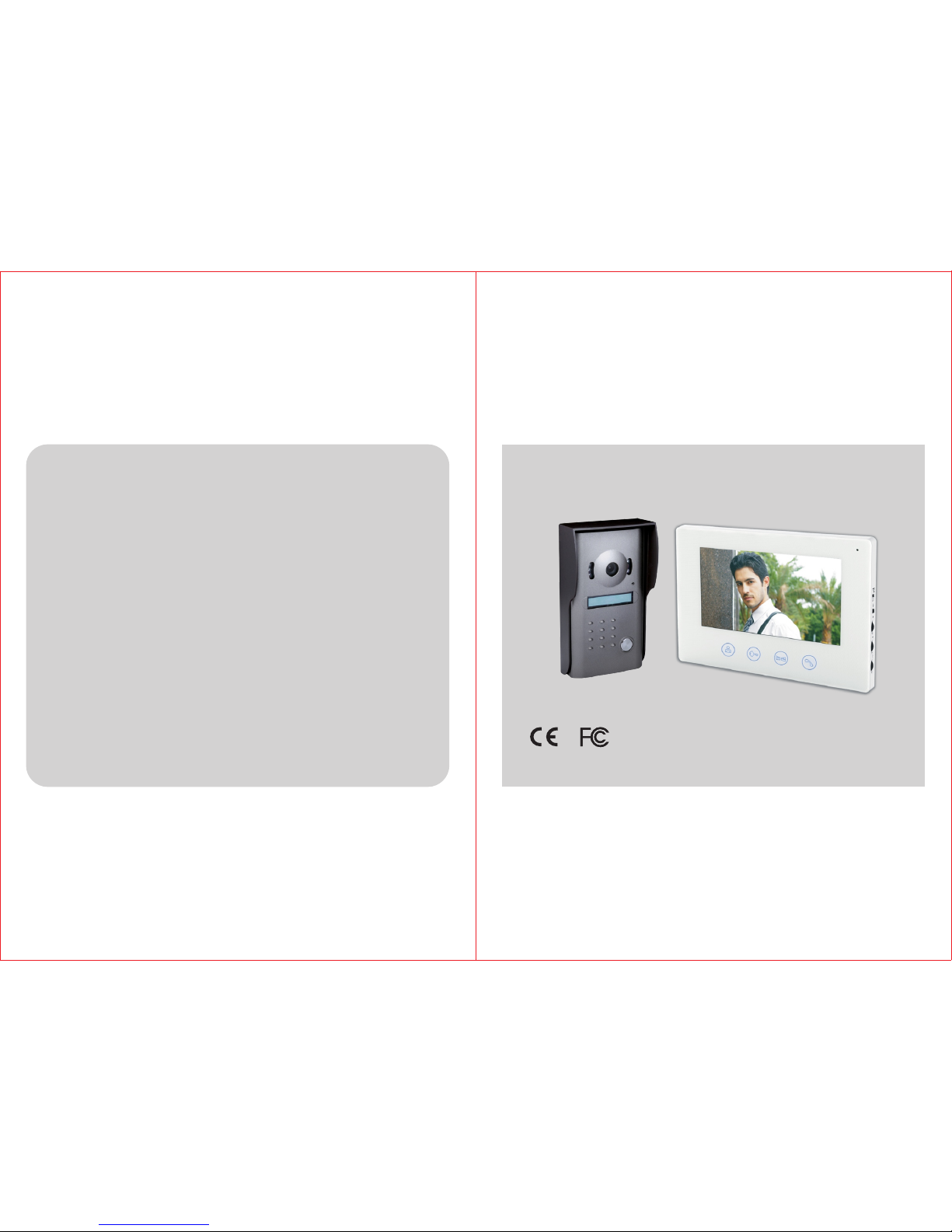
USER MANUAL
COLOR VIDEO DOORPHONE
MODEL:RL-B17M
Ve rsi on 1 .0
Product Description......................... ..........1
Features.....................................................1
Package Contents............................ ..........1
Safety Instruction.......................................2
System Installation.....................................2
Operation Instruction.................................6
Technical Specifications............................8
Tro uble Sh ooting.......................................10
Page 2
Safety Instruction
Product Description
The RL-B17M color video doorphone can be used to monitor, call, intercom
and unlock.It is a product that is very suitable for villa, single house, hotel,
office and etc, giving you the combined benefit of security and
convenience.
1) 7" TFT s creen w ith lo w p ower c onsumption, n o r adiation a nd h igh d efinition.
2) Ultra-thin designed indoor unit with touch pad for fashionable and luxury life.
3) Damage-proof, oxidation-proof and abrasion-proof metal alloy panel
outdoor unit.
4) Electrically controlled lock release function.
5) Unlock gate outdoor unit.
6) Monitor the outdoor.
7) Talking volume,brightness and chroma can be adjusted.
8) Enclosed with an adapter and 15m cable for DIY installation.
9) Indoor unit can be hung on the wall.
10) 16 chord melodies for option.
Features
Package Contents
1
2
Caution
·Keep the indoor unit away from high temperature such as near an oven or
under direct sunlight, and high humidity such as bathroom and greenhouse.
·Do not install the indoor unit close to a television or position with strong
jamming- the signals the TV and the intercom use can be interfered with
each other.
·Do not touch the unit with wet hands.
·Avoid throwing, dropping or hitting the units.
·Clean the camera or screen with a soft cloth. Do not use detergent,thinner,
volatile or corrossive liquid.
·Do not expose the camera of the outdoor unit to direct sunlight.
·Use the product under the circumstance of barrier-free and no inteference.
·When a car or a motorbike passes by, the image may become blurred or be
cut off due to the interference of radio wave.
2
System Installation
A. Indoor Uni t
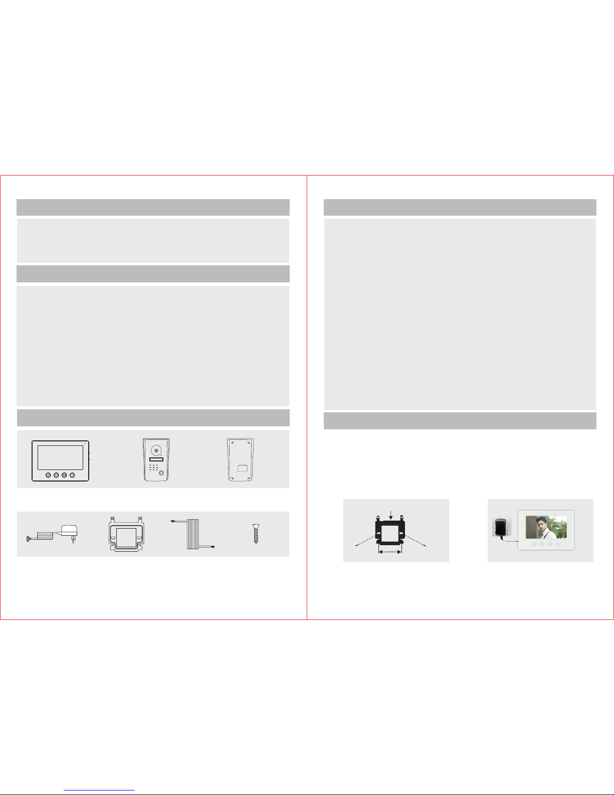
1) Fasten the bracket of the video indoor unit on the wall with screws.
Adopt 4 x 40PM screws to install it on 86 box.
Adopt 4 x 30BA screws to install it on the wall.
2) Hang the unit on the bracket after finishing wire connection.. Plug the
enclosed adapter into the sockets of AC power and the unit respectively.
1. To prevent damage, the adapter should be fastened on the wall according
to instruction.
2. Power plug as disconnecting device should be kept convenient to operate.
·Br acket x 1
·Ad apter x 1
·15 m Cab le x 1 ·Sc rew pac k x 1
63 mm
1 2
Bra cket
·In doo r Un it x 1
· Ra in sh ad e x1 ·Ou td oor U ni t x 1
Page 3

B. Outdoor Un it
4
3
1) Take off the screws on the bottom and remove the front cover.
2) Take off the ‘Room No,’ lid and write down your respective room/block
number and cover it again with the lid.
3) Install the Outdoor Unit 1.4m ~ 1.7m above the ground level
(according to the camera effect ).Avoid direct sunlight.
4) Fasten the outdoor unit on the wall with the enclosed screws (4x30BA).
5) Cover the zinc alloy panel and tighten up the screws on the bottom.
The enclosed cable is 15m, RVV4 connecting wire can be chosen if you
2
x 0.5mm
want to lengthen it to 15m~50m, RVV4 connecting wire can be chosen
2
x 0.75mm
if you want to lengthen it to 50m~100m.
Connect the wiring terminals 1,2,3,4 of indoor unit with wiring terminals 1,2,3,4 of
outdoor unit . The wiring terminals 5 & 6 of indoor unit are connected with electric
lock through RVV2 1.0 connecting wire. The wiring terminals 7 & 8 of indoor
2
x mm
unit are connected with the gate through RVV 2 x1.0mm connecting wire.
2
Please refer to the wiring diagram during connection.
Wiring Requ ir ement
C. Wiri ng D iagra m
Cab les:
1.A udio wi re
2.G round w ire
3.V ide o wir e
4.P ower wi re
Out door Un it
Ele ctron ic-lo ck
Ind oor Uni t
Gat e Unloc k
1
2
3
4
AC1 00-24 0V
50H Z/60H Z
DC1 2V
111
222
333
444555666777888
m
Talki ng dist ance< 40cm
Page 4

6
5
Operation Instruction
Indoo r Un it
Melod y (L/ M/ H)
Melod y Sel ectio n
Brigh tne ss
Chrom a
Volume
Wirin g
Termina l
Speak er
Monit or
Unolo ck
Micro pho ne
Gate Un loc k
Talk
B. Outd oo r Unit
1) Press CALL button of outdoor unit to call. The doorbell will ring and the images of visitors
will be shown on the indoor unit. Press TALK ( ) to activate the intercom. Touch TALK
( ) again to disconnect. Time duration of intercom and image is about 120s.
2) Touch UNLOCK ( ) button to release the electric door lock.
3) Touch GATE UNLOCK ( ) button to release the outdoor gate.
4) Touch MONITOR ( ) button to start monitoring outside. The monitoring time is about
40s. At the same time, you can touch TALK ( ) button to activate intercom with the
visitor at the door and press it again to stop monitor and conversation.
5) Turn the adjust knobs ( ), ( ) and ( ) on the side of indoor unit to adjust the
brightness,chroma and talking volume.
6) 16 chord molodies for option.
Wirin g ter minal
Camer a
Infra red l ight
Rain sh ade
Micro pho ne
Speak er
Call
Room nu mbe r
Page 5

7
Technical Specifications
Indoo r Un it
8
Scree n Si ze
Resol ut ion
Effec tive Are a
Outli ne S ize
Adapt er I nput Vol tage
Worki ng Dist ance
Power C on sumpt ion
Operating Temperature
Talking Ti me
Ralat iv e Humid ity
Monit or t ime
Adapt er O utput Vo ltage
&Curr en t
AC100 -2 40V 50H z/60H z
DC12V 11 00mA
800(H ) x 3( RGB) x 48 0(V)
154.0 8m m(H) x 85 .92mm (W)
215mm (W ) x 152mm (H) x 18m m(D)
Stati c St ate<0 .5W,
Worki ng Stat e<8W
10%~90%(R H)
120S±10 %
2
50m(4×0 .5 mm )
-10℃~+40℃
7
40S±10%
Outdo or U nit
Trouble Shooting
Problem
No Pict ure /Sign al
·Make su re al l the con nec tions a re se cure and
prope rly c onn ected .
·Make su re yo ur moni tor i s plugg ed in to a power
sour ce.
·Ma ke su re th ere is n oth ing o bst ructi ng th e v iew
o f t h e c amer a.
Solutions
No Pict ure ,
but int erc ommun ica tion
is norm al
No audi o whe n calli ng
The out doo r unit ca nno t
call th e ind oor one
Door Un loc k not
Funct ion ing
No one ca n hea r me
outsi de bu t I can hea r
them af ter c allin g
No one ca n hea r me
outsi de bu t I can hea r
them wh en mo nitor ing
·Make su re al l the con nec tions a re se cure an d
prop erl y con necte d.
·Make su re th ere is no thi ng obst ruc ting th e v iew
of the ca mer a.
·Make su re th e volum e noc h on the in doo r unit is
turne d up.
·Make su re th ere is no thi ng inte rfe ring with
the spea ker or micro pho ne on the in doo r unit
or the cam era .
·Make su re al l the con nec tions a re se cure an d
pr ope rly conn ected .
·Make su re al l the con nec tions a re se cure and
p roper ly co nnect ed.
·Make su re th e conne cti ons wit h the l ocks ar e
secu re and pr ope rly con nec ted.
·Make su re yo u have th e loc k wired t o a pow er
sour ce which is eno ugh to ma ke it opera te.
·Press TAL K key for t wo- way int erc om.
·Make su re al l the con nec tions a re se cure an d
prope rly c onnec ted .
·Press TAL K key for t wo- way int erc om Sinc e
simpl e t ouc h MONITOR all ows y ou to see and
hear out sid e but prev ent s the outs ide f rom
heari ng you
·Make su re al l the con nec tions a re se cure an d
prope r ly c onn ected
Infrared distance
Illumination
Working temperature
Resolution
Viewing angle
>4m
2LUX
-15℃~50℃
CMOS >380TV line,CCD >420TV line
180(H)x104(W)x54(D) mm
60° wide angle
Dimensions
 Loading...