

Page 1

Model RF802EW
Wireless Router/Access Point
User Guide
Page 2

User Guide
Wireless Router/Access Point
Model RF802EW
P/N S0000178 Revision B
Copyright
This publication may not be reproduced, in whole or in part, without prior expressed written permission
from Multi-Tech Systems, Inc. All rights reserved.
Copyright © 2001 by Multi Tech Systems, Inc.
Multi-Tech Systems, Inc. makes no representations or warranties with respect to the content hereof and
specifically disclaims any implied warranties of merchantability or fitness for any particular purpose.
Furthermore, Multi-Tech Systems, Inc. reserves the right to revise this publication and to make changes
from time to time in the content hereof without obligation of Multi-Tech Systems, Inc. to notify any person
or organization of such revisions or changes.
Record of Revisions
Revision Date Description
A 06/06/01 Manual released.
10/04/01 Recreated PDF.
B 10/22/01 Added Web browser configuration and management chapter, Wireless Setting
section to the Telnet chapter, Add MAC Access Control section to the
RouteFinder Manager chapter.
Patents
This device is covered by one or more of the following patents: 6,219,708; 6,031,867; 6,012,113;
6,009,082; 5,905,794; 5,864,560; 5,815,567; 5,815,503; 5,812,534; 5,809,068; 5,790,532; 5,764,628;
5,764,627; 5,754,589; D394,250; 5,724,356; 5,673,268; 5,673,257; 5,644,594; 5,628,030; 5,619,508;
5,617,423; 5,600,649; 5,592,586; 5,577,041; 5,574,725; D374,222; 5,559,793; 5,546,448; 5,546,395;
5,535,204; 5,500,859; 5,471,470; 5,463,616; 5,453,986; 5,452,289; 5,450,425; D361,764; D355,658;
D355,653; D353,598; D353,144; 5,355,365; 5,309,562; 5,301,274. Other Patents Pending
Trademarks
Trademark of Multi-Tech Systems, is the Multi-Tech logo. Windows, Windows 95, 98, NT and 2000 are
trademarks of Microsoft. All other trademarks are owned by their respective companies.
World Headquarters
Multi-Tech Systems, Inc.
2205 Woodale Drive
Mounds View, Minnesota 55112 U.S.A.
(763) 785-3500 or (800) 328-9717
U. S. FAX (763) 785-9874
Technical Support (800) 972-2439
Internet Address: http://www.multitech.com
Page 3

Contents
Chapter 1 - Introduction .............................................................. 6
Description of the RF802EW RouteFinder ............................................ 6
Front Panel..................................................................................... 7
Back Panel ..................................................................................... 7
Typical Applications ......................................................................... 8
Connecting a Remote Site via Cable Modem ....................................8
Connecting a Local Site to the Internet ........................................... 8
Specifications ................................................................................. 9
Chapter 2 - Hardware Installation .............................................. 11
Safety ..........................................................................................11
Unpacking the RF802EW .................................................................11
Cabling ......................................................................................... 12
Chapter 3 - Software Installation and Configuration .................. 14
Software Installation ...................................................................... 14
Using RouteFinder Setup Wizard ...................................................... 15
Remote Access .......................................................................... 19
Testing Your Connection ..................................................................23
Chapter 4 - Web Browser Management and Configuration ......... 25
Using a Web Browser to Configure Your RouteFinder ........................... 25
Setup Wizard .................................................................................26
Setup Wizard Screen ......................................................................27
Setup Wizard - Time Settings ..................................................... 28
Setup Wizard - ADSL/Cable ISP Settings....................................... 29
Setup Wizard - ISP Additional Settings (PPPoE Settings) ................. 30
Setup Wizard - Wireless Settings ................................................. 31
Setup Wizard - Modem Settings................................................... 32
Setup Wizard - Save and Restart ................................................. 32
Device Information ......................................................................... 33
Device Status ................................................................................34
Advanced Settings .........................................................................35
Advanced Settings - DHCP Server Settings ................................... 35
Advanced Settings - Virtual Server Settings .................................. 36
Advanced Settings - Static Routing .............................................. 37
Advanced Settings - Dynamic Routing .......................................... 38
Advanced Settings - Modem String Settings .................................. 39
Advanced Settings - Administrative Settings .................................. 40
System Tools ................................................................................. 41
System Tools - Intruder Detection Log .......................................... 41
System Tools - Display Routing Table............................................ 42
System Tools - System Diagnosis................................................ 43
System Tools - Load Default Settings ........................................... 44
System Tools - Upgrade Firmware ............................................... 45
System Tools - Reset Device ....................................................... 46
Page 4

Chapter 5 - Using Telnet to Configure Your RouteFinder ............ 48
Starting a Telnet Session .................................................................48
Server Menu Options.................................................................. 49
Chapter 6 - RouteFinder Manager ............................................... 55
Accessing the RouteFinder Manager Software .................................... 55
Description of the RouteFinder Manager Main Screen .......................... 56
General Settings Option on the Manager Main Screen .........................60
General Settings Options ............................................................ 61
Remote Access Settings ............................................................. 66
Enable IP Mapping - Virtual Server ............................................... 67
Port Settings Option from the Manager Main Screen ........................... 69
LAN DHCP Server Option from the Manager Main Screen ..................... 74
Routing Settings Option from the Manager Main Screen ......................76
Filter Settings Option from the Manager Main Screen ..........................78
Wireless Settings Option from the Manager Main Screen ..................... 82
MAC Access Control Option from the Manager Main Screen ..................83
Chapter 7 - RouteFinder Monitor ................................................ 85
Accessing the RouteFinder Monitor ...................................................85
Screen Options ..............................................................................85
Chapter 8 - LAN Client Settings .................................................. 94
Introduction ..................................................................................94
Setting Up Remote Access Clients .................................................... 94
Accessing a Windows NT Server .................................................. 94
Accessing a Novell Server ......................................................... 104
Accessing a Windows NT Server and a Novell NetWare Server ....... 107
Accessing a Unix Server ........................................................... 112
Make New Connection (Windows 2000 only)................................ 114
Chapter 9 - LAN-to-LAN Settings .............................................. 117
Chapter 10 - Troubleshooting ................................................... 120
Chapter 11- Service, Warranty, and Technical Support ............ 124
Software User License Agreement .................................................. 126
Technical Support ......................................................................... 128
Appendix A - Regulatory Compliance Information .................... 131
Appendix B - Tools for your RF802EW ...................................... 132
Appendix C - Cabling Diagrams................................................. 134
Index ........................................................................................ 140
Page 5

Chapter 1
Introduction
Page 6

Chapter 1 - Introduction
Description of the RF802EW RouteFinder
Congratulations on the purchase of the Multi-Tech Systems RouteFinder model
RF802EW, one of the finest broadband routers available today.
The RouteFinder RF802EW provides wireless users with seamless access to their
existing wired LAN, enabling them to share broadband access to the Internet as well as
other resources. Using the IEEE 802.11b wireless standard, the RouteFinder provides
increased speed--up to 11 Mbps--and mobility between the desktop, conference room,
or campus. It supports a DSL or cable modem connection to the Internet to provide
shared Internet access for up to 253 users. The RF802EW includes one asynchronous
port for backup Internet access or dial-in remote access.
Wireless Networking. The RouteFinders integrated IEEE 802.11b-compliant access
point provides mobility, enabling access to shared resources without requiring a
physical connection. The RouteFinder also communicates with other access points on
the network to provide roaming from one cell to another.
Connects up to 253 internal IP addresses to the Internet with broadband
speed. The RouteFinder can be configured as a DHCP server to handle requests for
Internet services and route to and from the ISP. Up to 253 internal IP addresses are
connected to the Internet with only one IP account. The WAN Ethernet port has a
bandwidth of 10 Mbps which is 179 times faster than a 56k modem and can support
DSL or cable speeds of up to 5 Mbps.
Network Security. The RouteFinder uses 64-bit WEP encryption for wireless LAN
security. WEP prevents intruder access to the network and prevents the capture of
wireless LAN traffic by eavesdropping. The RouteFinder uses the NAT protocol to
provide security from hackers attempting to access the office LAN without the extra cost
of a firewall. It implements firewall and gateway security for LAN-based resources.
Additionally, the RouteFinder supports Internet access restriction by IP address, client
protocols or a list of forbidden sites.
Dial Backup or Dial-in RAS Port. The RouteFinder also provides an additional
asynchronous port that, when connected to a dial-up modem or ISDN terminal adapter,
serves as a backup resource for Internet access if your cable or DSL service goes down.
It can also serve as dial-in remote access for your telecommuters or mobile users.
Virtual Server Support. In addition to providing shared Internet access, the
RouteFinder can support Web, FTP or other Internet servers. Once configured, the
RouteFinder accepts only unsolicited IP packets addressed to the Web or FTP server.
LAN Segmentation. For added LAN security, the RouteFinder can be used to segment
the LAN by connecting the corporate servers to one RouteFinder Ethernet port and the
Internet Servers to the other Ethernet port. This configuration puts the corporate
servers behind a firewall and the Internet servers outside the firewall. To continue to
provide Internet access, connect a modem, or ISDN terminal adapter to the
RouteFinders asynchronous port.
Chapter 1 - Introduction
The RouteFinder RF802EW
Multi-Tech Systems, Inc. RouteFinder RF802EW User Guide
6
Page 7
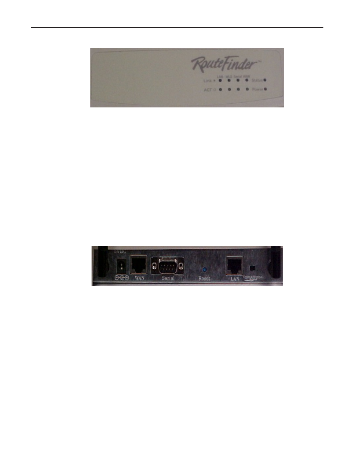
Front Panel
Front Panel Description
Link Lights when the LAN client is correctly connected to the 10/100 LAN.
ACT Blinks when transmitting or receiving packets.
LAN Lights when a successful connection to the 10/100 LAN is established.
WLS Lights when a wireless connection is established.
Serial Lights when the Serial async port is properly connected to a remote site.
WAN Lights when a successful connection to the 10Base-T WAN is established.
Status Blinks when updating flash ROM or rebooting.
Power Lights when power is being supplied to the router.
Chapter 1 - Introduction
RF802EW Front Panel
Back Panel
Back Panel Description
Power 5V DC The 5V DC power socket is used to connect the device to the AC
10 BT WAN The WAN port is used to connect the router to a DSL or Cable
Serial The Serial async port connects the router to a standard modem
10/100M Connects the Router to a 10/100 Base-T Ethernet LAN.
Reset Press and hold for three seconds to reset the router to factory
Uplink/Normal Slide the switch to the Uplink position to use the LAN port to
RF802EW Back Panel
power adapter.
modem.
(optional).
defaults.
expand your network by connecting a network cable to another
router, switch, or hub. To connect the port to a LAN client
workstation, slide the switch to the Normal position.
Multi-Tech Systems, Inc. RouteFinder RF802EW User Guide
7
Page 8
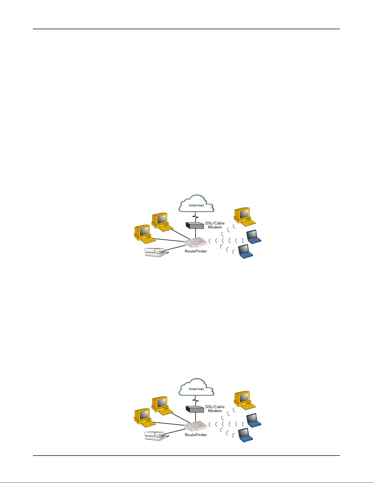
Typical Applications
The following examples provide information about typical applications using the
RF802EW. They describe using the RF802EW to connect a remote site via a cable
modem, using the RF802EW to segment a local area network, and using the RF802EW
to connect a LAN to the Internet using one shared IP address.
Connecting a Remote Site via Cable Modem
In the following example the RF802EW is used to connect a LAN to the Internet via DSL
or a cable modem.
Kernal: NAT (outgoing TCP/IP connection sharing a single Internet IP address
or using multiple IP mapping)
Virtual Server (allowing incoming specific TCP/IP service request
redirect to an internal server)
Static Routing (Routing table setting to Internal Local Gateways)
Firewall
External: Fixed External Port IP or DHCP client (Dynamic IP assigned)
Internal: Device Fixed IP
DHCP Server
Chapter 1 - Introduction
Connect Remote Site via Cable Modem
Connecting a Local Site to the Internet
In this application, the RF802EW is used to connect up to 253 Internal IP addresses to
the Internet using a single shared external IP address.
Kernal: NAT (outgoing TCP/IP connection sharing single External Port IP or using
multiple IP Mapping)
Virtual Server (allow incoming specific TCP/IP service request redirect
to internal server)
Firewall
External: Fixed External Port IP and mask DNS IP, Gateway IP or DHCP client
(Dynamic IP for the device, DNS and Gateway assigned.)
Internal: Device Fixed IP
DHCP Server
Connect Local Site (I External IP address = 253 Internal IP addresses)
Multi-Tech Systems, Inc. RouteFinder RF802EW User Guide
8
Page 9

Specifications
Hardware ARM RISC CPU
LAN Port Interface: 1 10Base-T/100BaseTX RJ-45 Connection
WAN Ports 1 x 10Base-T
Wireless
Access Point IEEE 802.11b for wireless LAN
Protocols Security: PAP/CHAP, NAT Firewall, RADIUS, Callback, WEP
Power Output 5V DC, 2000mA
Dimensions 7.1 x 4.9 h x 1.4 d
Weight 380g
Memory RAM: 4MB
Operating
Environment Temperature Range: 32-120 degrees F (0-50 degrees C)
Approvals FCC Part 15 Class B & ETS 300 328
Warranty 2-year warranty
Chapter 1 - Introduction
32 bit, 40MHZ
4MB DRAM and 512k Flash ROM
UART Serial port controller
Standard: 802.3
1 x RS232 (V.24)
DTE Speed: Up to 230K asynchronous
Date Rates: 11, 5.5, 2, 1 Mbps data rate per channel
RF Frequency: 2.4-.24835 Ghz
Emission Type: Direct Sequence Spread Spectrum
Operating Range: Up to 100 meters indoors and 300 meters outdoors
Antenna: Dual Dipole with Diversity
Antenna Gain: 2 dB MAX
Network: TCP/IP, IPX, DHCP, PPP, PPPoE
Routing: Static, RIP 1, VPN, IPSec & PPTP Pass-Through
Filtering: Protocol, port number, and IP address
(18.1 cm x 12.5 cm x 2.5 cm)
13 oz.
Flash ROM: 512k
Humidity: 25-85% non-condensing
Multi-Tech Systems, Inc. RouteFinder RF802EW User Guide
9
Page 10

Chapter 2
Hardware Installation
Page 11

Chapter 2 - Hardware Installation
Safety
1. Never install telephone wiring during a lightning storm.
2. Never install telephone jacks in a wet location unless the jack is specifically designed
for wet locations.
3. This product is to be used with UL and cUL listed computers.
4. Never touch uninsulated telephone wires or terminals unless the telephone line has
been disconnected at the network interface.
5. Avoid using a telephone during an electrical storm. There may be a remote risk of
electrical shock from lightening.
7. Do not use the telephone to report a gas leak in the vicinity of the leak.
8. To reduce the risk of fire, use only No. 26 AWG or larger telecommunications line Cord.
Unpacking the RF802EW
Chapter 2 - Hardware Installation
The RF802EW shipping box contains the following items:
System CD
Tucows CD
Power Supply
The RouteFinder RF802EW
The RF802EW RouteFinder Quick Start Guide
If any of the items is missing or damaged, please contact Multi-Tech Systems.
Multi-Tech Systems, Inc. RouteFinder RF802EW User Guide
11
Page 12
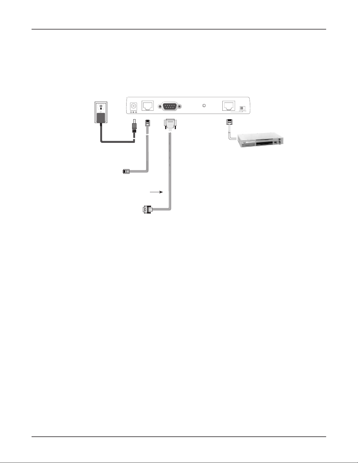
Cabling
Cabling your RouteFinder requires making the appropriate connections to PCs, Cable, or
DSL modem, analog modem or ISDN TA (optional), AC power and the router. Because
this device also acts as a DHCP server, after your device is properly cabled, you will
need to follow the configuration instructions provided in the Software Installation and
Configuration chapter.
Chapter 2 - Hardware Installation
Power Connection
To Cable Modem
or DSL Modem
To optional
Modem or
5VDC
Serial Cable
ISDN TA
WAN
Reset
LAN
Uplink/Normal
Optional
Uplink
Hub
Cabling the RouteFinder RF802EW
1. Before beginning, turn the power off on all network devices (PCs, Cable, DSL
modems, analog modems, ISDN TAs and the router).
2. Connect the Ethernet port of each PC or network device to the LAN port.
3. If you are using an analog modem, connect it to the Serial Async port.
4. If you are using the Uplink option to connect to another network segment, slide
the Uplink/Normal switch into the Uplink position. Connect the LAN cable to
LAN port #1. Plug the other end of the LAN cable into another hub, router, or
switch.
Note: If you are not using the Uplink feature, place the switch in the Normal
position.
5. Connect a network cable from the cable or DSL modem to the 10 BT WAN port.
6. Connect the provided power supply cable to the 5V DC power port on the back of
the router. Plug the power supply into an AC power outlet as shown above.
7. Power on your DSL or Cable modem.
8. If you are using an analog modem or ISDN TA, power on the device.
9. You are ready to configure software for your RouteFinder and network PCs.
Multi-Tech Systems, Inc. RouteFinder RF802EW User Guide
12
Page 13

Chapter 3
Software Installation
and Configuration
Page 14

Chapter 3 - Software Installation and Configuration
Chapter 3 - Software Installation and Configuration
Before beginning the installation process, ensure that your system meets all hardware
and software requirements:
Intel 486 or higher processor.
10/100 Base-T cable to connect the RF802EW to the network.
One DSL or Cable Modem.
A networked computer with Windows 95/98/2000, Windows NT 3.5 or higher and
TCP/IP protocol installed (or, a non-Windows system with TCP/IP properly installed
to enable Telnet configuration).
Any PPP supported communication application for Dial-In operation.
TCP/IP installed and configured on each workstation accessing the Internet.
Software Installation
The software installation process involves installing the RouteFinder Utilities, including
RouteFinder Setup Wizard, RouteFinder Manager and RouteFinder Monitor. A
description of each component follows:
RouteFinder Setup Wizard
The RouteFinder Setup Wizard provides a step-by-step process to assist you in entering
all the basic settings needed to configure your RF802EW for general use. All settings
that are entered in the Setup Wizard can be found in their respective menus in the
RouteFinder Manager.
RouteFinder Manager
RouteFinder Manager is the main program used to configure all settings for your
RF802EW. Complete information about options within the RouteFinder Manager can be
found in the RouteFinder Manager chapter in this User Guide.
RouteFinder Monitor
RouteFinder Monitor is a multi-purpose utility designed to let you know the status of
your RF802EW connection. The monitor offers the ability to point and click on an event
to access troubleshooting procedures. Refer to the RouteFinder Monitor chapter in this
User Guide for more information.
Multi-Tech Systems, Inc. RouteFinder RF802EW User Guide
14
Page 15
Using RouteFinder Setup Wizard
Note: Before beginning this procedure, ensure that your RF802EW is properly
connected to the network and that the power is turned on.
After installing the software, you may return to the RouteFinder Setup Wizard at any
time, by clicking Start | Programs | RouteFinder Manager | RouteFinder Wizard.
Before running the Setup Wizard, it is strongly recommended that you exit all Windows
programs.
1. Insert the RF802EW System CD into your computers CD-ROM drive. The
RF802EW System CD window appears.
Note: If Autorun is disabled on your computer, use Windows Explorer to view
the contents of the CD. Double-click the CD icon to display the RF802EW
System CD main window.
2. Click Install Software.
3. Follow the on-screen instructions to install the software.
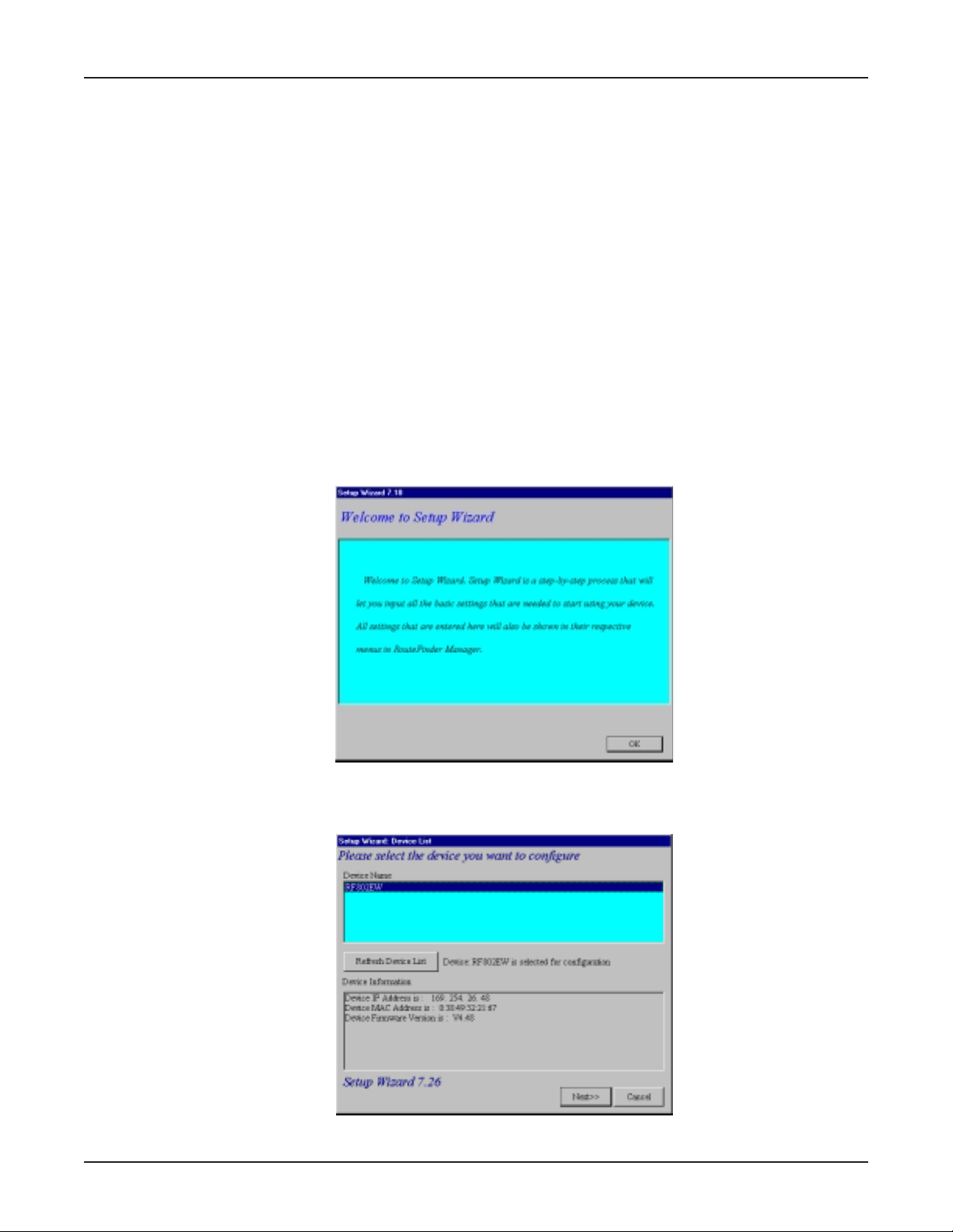
4. When the software installation completes, the Setup Wizard dialog box
displays. Click OK.
Chapter 3 - Software Installation and Configuration
5. The Setup Wizard: Device List dialog box displays. The Setup Wizard
automatically checks your network for available network devices and displays
them.
Select the device you wish to configure from the Device Name list.
Multi-Tech Systems, Inc. RouteFinder RF802EW User Guide
15
Page 16
Chapter 3 - Software Installation and Configuration
Record the values presented in the Device Information panel for later
reference.
Device IP Address ______________________
Device MAC Address ____________________
Device Firmware Version _________________
Click Next.
Note: If a message appears indicating the device is not found, or you do not see
the device you are attempting to configure listed, click Refresh Device List.
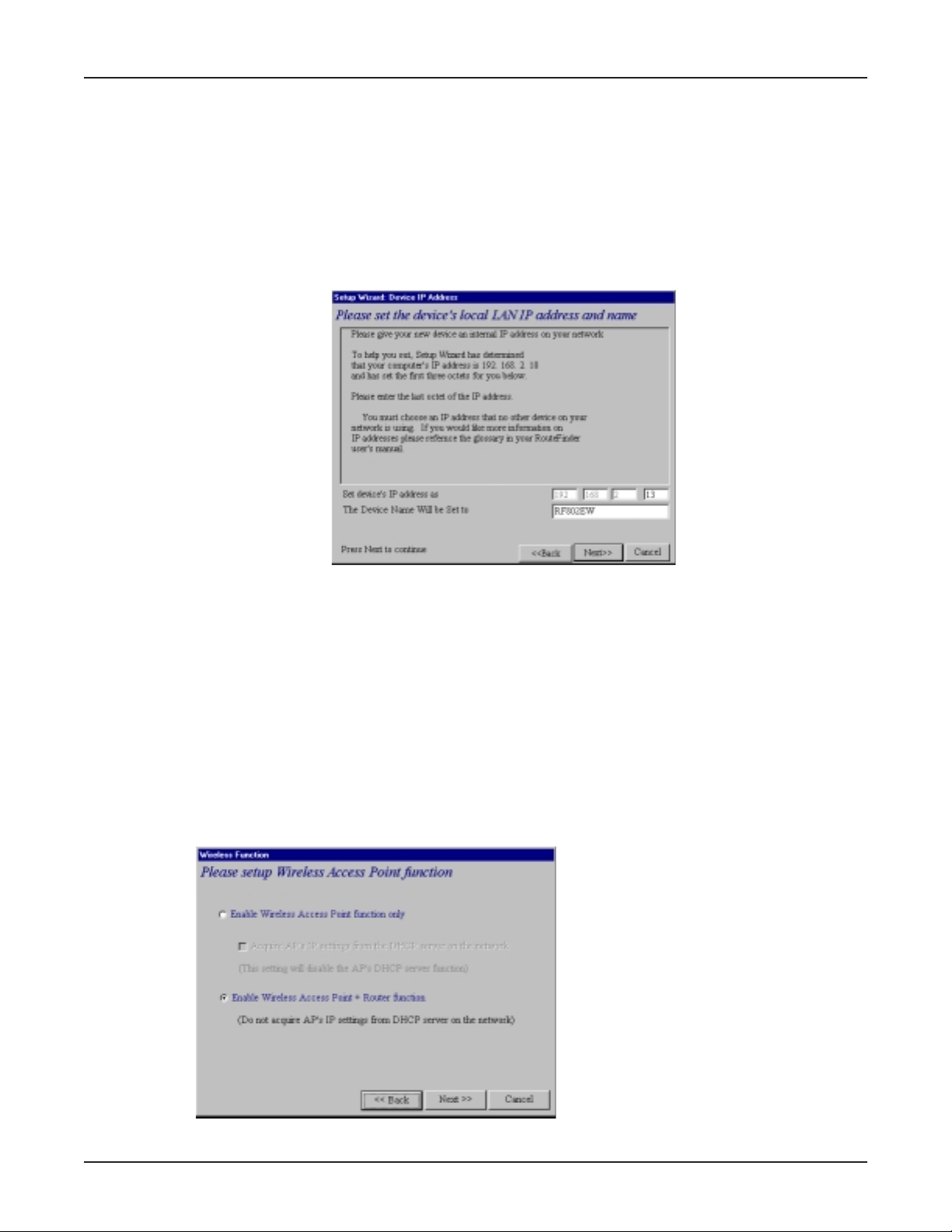
6. The Setup Wizard: Device IP Address dialog box displays.
Enter your local internal networks IP address for this device.
The Setup Wizard will automatically detect the first three octets of your local IP
address. You must enter the last octet only.
If you wish, you can change the network name of your RouteFinder. If your ISP
requires your device to have a name, you may use the name entered here.
Click Next to continue. The device will search the network to ensure that the IP
address is valid. This may take several seconds.
Note: If your ISP provided you with an IP address, do not enter that address.
Enter the IP address for this device on your local network. Refer to the Glossary
for additional information on IP addressing.
7. The Wireless Function dialog box displays.
Select the function for the wireless port function by selecting Enable Wireless
Multi-Tech Systems, Inc. RouteFinder RF802EW User Guide
16
Page 17
Chapter 3 - Software Installation and Configuration
Access Point function only, or Enable Wireless Access Point + Router
function. If you are using NAT Enabled, you may also select Enable PPPoE.
Select Enable Wireless Access Point function only to set APs IP manually
or acquire an IP address from a DCHP server.
Select IP Routing (NAT Disabled) to allow the RF802EW to function as a
router between the IP segment of the server and another IP segment. This
option is ideal for organizations needing to segment workgroups.
Select Enable PPPoE to use the RF802EW with a time-base, rather than
fixed-cost DSL modem connection. Enter the User Name and Password
provided by your ISP. This option is most often used when connecting via
DSL to the Internet.
Note: Enable PPPoE is valid only when IP Routing (NAT Enabled) is selected.
Click Next accessing the Internet. This option is most often used when the
RF802EW is connected to a DSL or cable modem, or when the IP segment of
the server needs firewall protection.
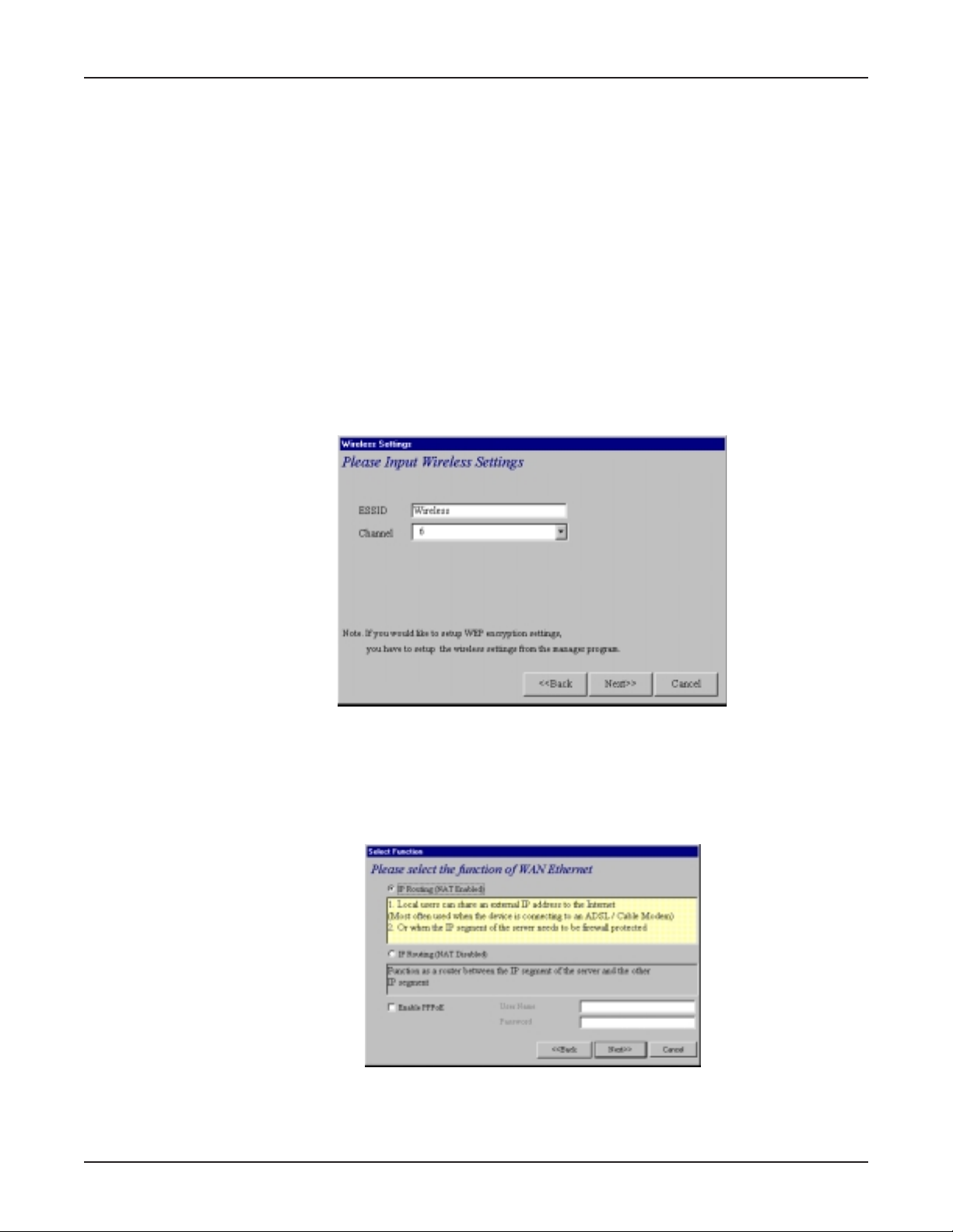
8. The Wireless Settings dialog box displays.
In the ESSID box, enter the wireless ID. Wireless is the default ID. From the
Channel list, select a channel. 6 is the default channel. All workstations must
have the same ESSID Make sure that the channel is correct for your network.
Click Next.
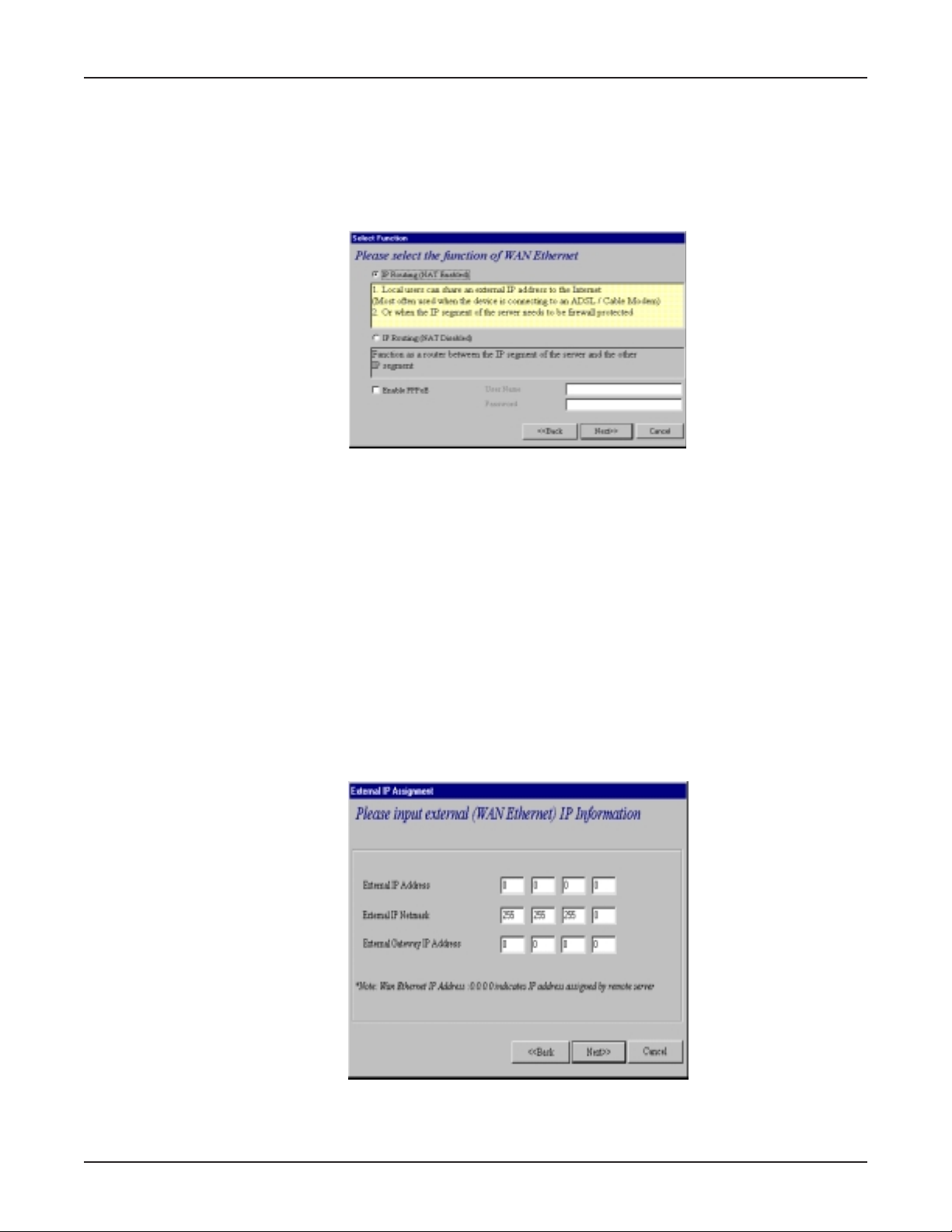
9. The Select Function dialog box displays.
Select IP Routing (NAT Disabled) to allow the RF802EW to function as a router
between IP segments. This option is ideal for organizations needing to segment
workgroups.
Multi-Tech Systems, Inc. RouteFinder RF802EW User Guide
17
Page 18
Chapter 3 - Software Installation and Configuration
Select Enable PPPoE to use the RF802EW with a time-base, rather than fixed-cost
DSL modem connection. Enter the User Name and Password provided by your ISP.
This option is most often used when connecting via DSL to the Internet.
Note: Enable PPPoE is valid only when IP Routing (NAT Enabled) is selected.
Click Next.
10. The External IP Assignment dialog box displays.
Enter the WAN Ethernet IP address information provided by your ISP or other
external network administrator.
In the External IP Address box, enter the WAN Ethernet IP Address.
In the External IP Netmask box, enter the Netmask of the WAN Ethernet IP
Segment. For Class C networks, the Netmask is generally set to 255.255.255.0).
In the External Gateway IP Address box, enter the IP address of the Gateway to
the destination network.
Note: If your ISP uses dynamic IP addressing (DHCP), leave the External IP address
and the External Gateway IP address at the default values of 0.0.0.0. Set the
External IP Netmask to the default value of 255.255.255.0.
Click Next.
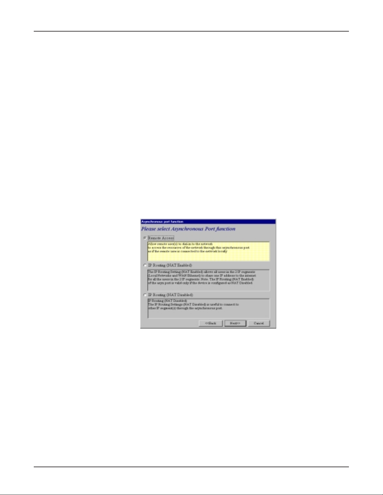
11. The Asynchronous port function dialog box displays. Select 1) Remote Access,
2) IP Routing (NAT Enabled) or 3) IP Routing (NAT Disabled).
Select Remote Access to allow remote users to dial-in to the network to access
resources as if the remote user is connected to the network locally. See the Remote
Access instructions for more information.
Multi-Tech Systems, Inc. RouteFinder RF802EW User Guide
18
Page 19
Chapter 3 - Software Installation and Configuration
Select IP Routing (NAT Enabled) to allow all users in the two IP segments (LAN
and WAN Ethernet) to share one IP address to the Internet. You may also select this
option to use the serial async port for dial backup in the event the DSL or cable
modem becomes unavailable.
Select IP Routing (NAT Disabled) to connect other IP segments through the serial
async port. See the IP Routing instructions continue on page 26.
Note: The IP Routing (NAT Enabled) feature of the serial async port is valid only if
the WAN port is configured as NAT Disabled.
Click Next.
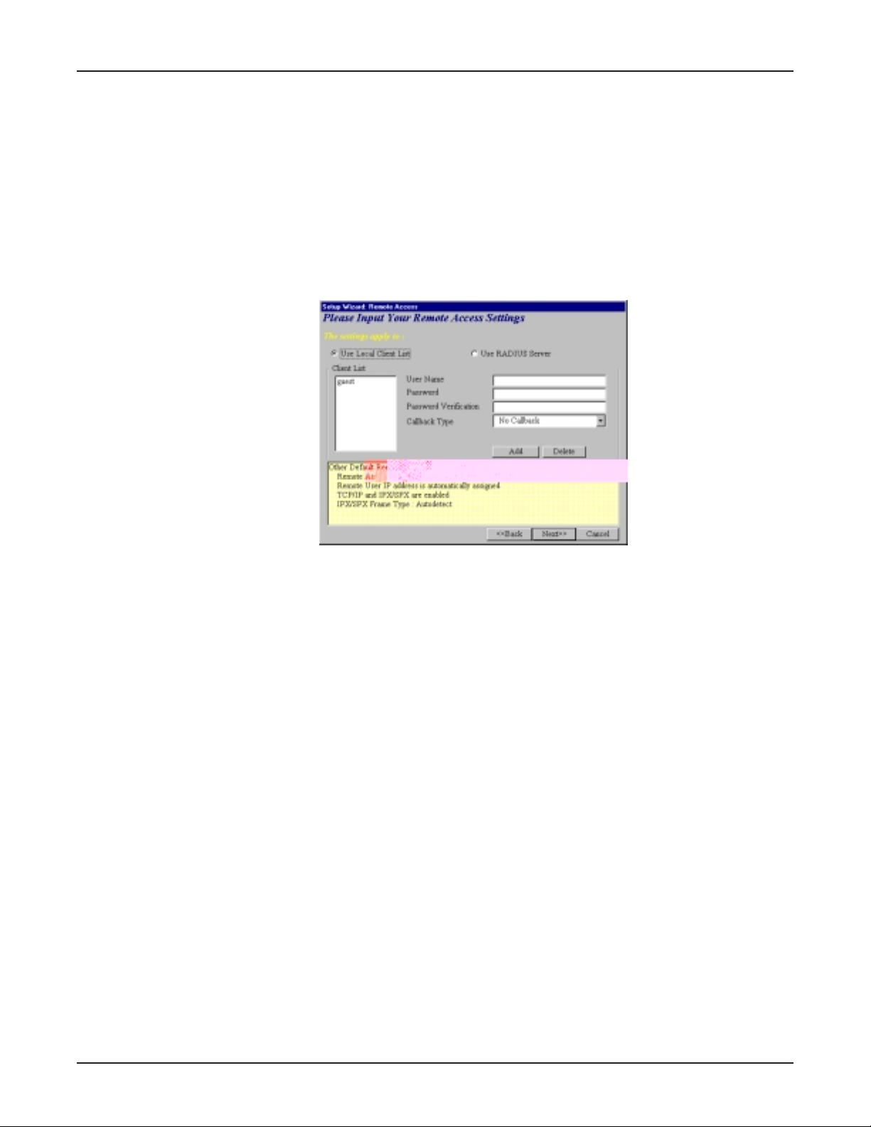
Remote Access
You must define the location of your remote user account database by selecting Use Local Client
List or Use RADIUS Server.
Note: The Local Client List allows you to add a maximum of 64 users.
Use Local Client List
Use Local Client List allows you to create an authentication database consisting of user names,
passwords and dial-in options for each remote user. You must provide the following information for
each client:
User Name
Enter the User Name to authenticate the remote dial-in user.
Password
Enter the Password to authenticate the remote dial-in user. Passwords are limited to 16 characters.
Password Verification
Re-enter the remote dial-in user’s password.
Callback Type
Select one of the following three callback options for each remote client:
• No Callback: Select this option to allow the remote user to immediately connect to the network
after being authenticated. This is the default setting.
• Fixed Callback: This option allows you to specify a fixed callback telephone number for the
user. After the PPP negotiation, the device will disconnect, then callback the telephone number
you entered. This option is best used for clients requiring callback security while dialing-in from
the same location each time.
Multi-Tech Systems, Inc. RouteFinder RF802EW User Guide
19
Page 20
Chapter 3 - Software Installation and Configuration
Variable Callback: Select Variable Callback for remote users that travel or
dial-in from various locations and need callback security. This option allows
clients to specify the callback telephone number each time they connect to the
network.
Click Add after entering information for each Local Client.
Click Next and continue with Step 10 when all users have been added to the database.
Use RADIUS Server
Select this option if you would like your remote clients to be authenticated on a RADIUS
server. You must enter the following RADIUS Server Settings:
RADIUS Access Server IP Address
Enter the IP address of the RADIUS Access Server.
RADIUS Accounting Server IP Address
Enter the IP address of the RADIUS Accounting Server.
Secret
Enter your Shared Secret.
Secret Verification
To confirm your Shared Secret, re-enter your Shared Secret.
Note: In most cases, the RADIUS Access Server and the RADIUS Accounting Server
are the same server, so the IP addresses will also be the same.
Click Next.
Multi-Tech Systems, Inc. RouteFinder RF802EW User Guide
20
Page 21
Chapter 3 - Software Installation and Configuration
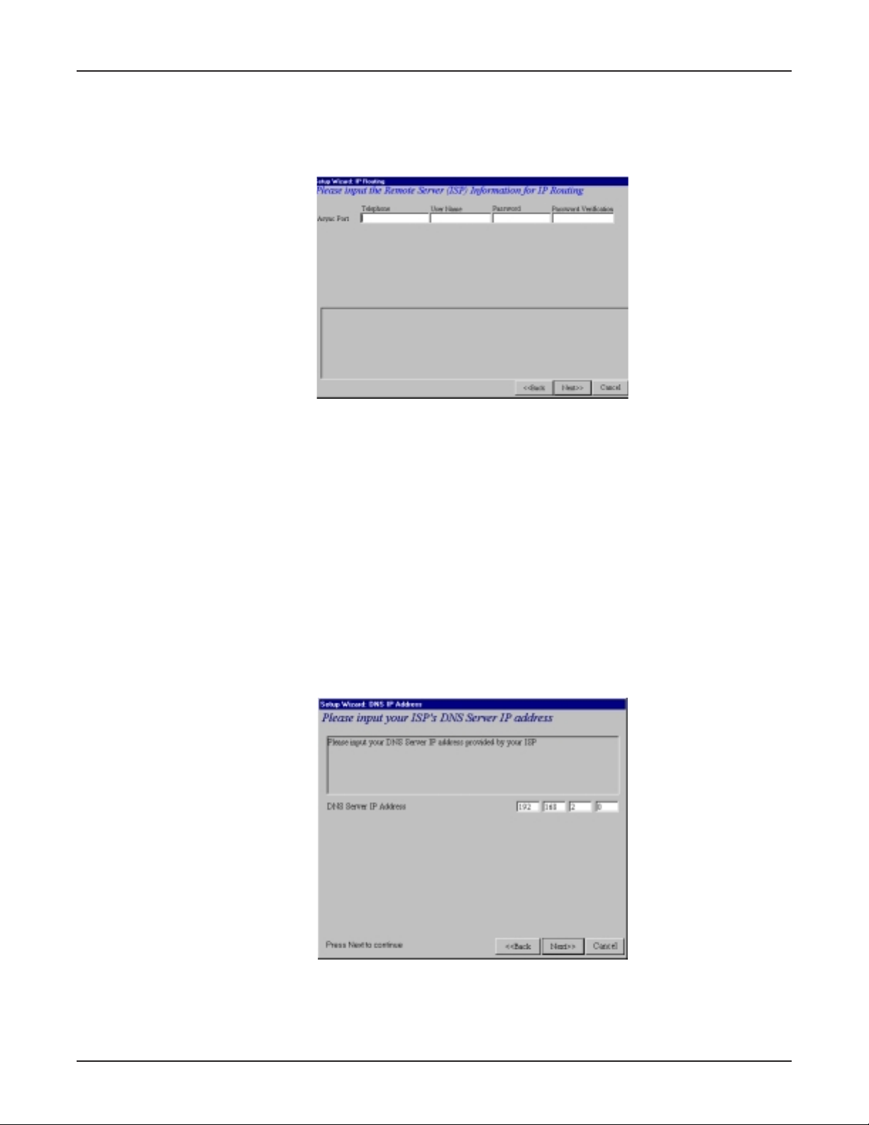
IP Routing (NAT Enabled) and IP Routing (NAT Disabled)
Select from the Asynchronous Port Function Screen
If you select IP Routing for the asynchronous port, the Setup Wizard: IP Routing dialog
box displays.
Enter the information required to dial-up and login to your ISPs remote server:
Telephone Number
Enter the phone number used to dial your remote server (ISP).
Note: If you must dial a number to get an outside line (for example, 9, or 0),
enter the required number plus a w (wait) or a comma in the Telephone box (for
example, 9w555-2323 or 9,,5552323). Each comma provides a 3-4 second delay.
User Name
Enter the User Name for your remote server or ISP account.
Password
Enter the Password for your remote server or ISP account.
Password Verification
Re-enter the password for your remote account.
Click Next.
12. The Setup Wizard: DNS IP Address dialog box displays.
Enter your ISPs DNS Server IP address. If you are not sure of the IP address,
contact your ISP. Refer to the Glossary in the User Guide for more information
about the DNS Server.
Click Next.
Multi-Tech Systems, Inc. RouteFinder RF802EW User Guide
21
Page 22
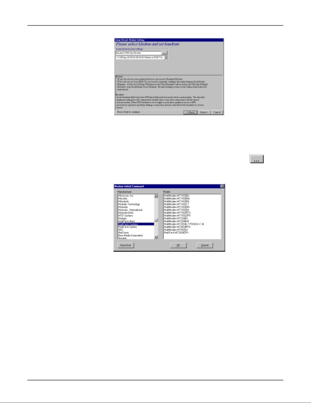
Chapter 3 - Software Installation and Configuration
13. The Setup Wizard: Modem Settings dialog box displays.
Use this dialog box to define your modem Manufacturer, Model and the DTE
baudrate (speed) of communication between the RF802EWs serial async port and
your modem or ISDN TA.
Note: If you do not have a device attached to the serial async port, use the default
modem values, and click Next.
14. To select your modem, in the Asynchronous port settings box, click . The
system loads modem information.
15. The Modem Initial Command dialog box displays.
Select your modem manufacturer, then select the model from the list provided.
Click OK. If your modem is not listed and you have a driver disk, click Have Disk...
to install your modem.
Note: This setting configures the initial string of the RF802EW asynchronous port so
that it will know how to communicate with your modem. If using an analog modem
and this modem is not included in the selection list, in most cases, Standard Modem
will work. If you are using an ISDN TA, refer to the ISDN TAs User Guide for
information on the initialization and hang up strings. Use RouteFinder Manager to
enter modem strings.
16. The Setup Wizard: Modem Setting dialog box re-displays. Use the
Asynchronous port settings list to select the baudrate. Select the DTE speed (the
speed of communication between the asynchronous port of the RF802EW and the
modem). For DCE speed compression modems, this value can normally be set to
about 4 times the speed of your modem. Keep in mind that if you set the baudrate
too high, the dial-up connection may fail.
Note: You may need to set a lower baudrate since the theoretical maximum
connection speed may not be attainable due to variations in quality of phone line
and ISP connections.
Click Next to complete the basic configuration.
Multi-Tech Systems, Inc. RouteFinder RF802EW User Guide
22
Page 23
Chapter 3 - Software Installation and Configuration
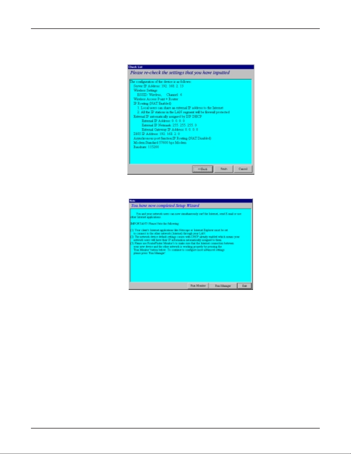
17. The Check List dialog box displays summarizing your configuration selections.
Ensure that all values have been correctly entered. If you find an incorrect setting,
click Back to return to the screen containing the error and correct it. When
complete, click Next to return to the Check List dialog box.
Click Finish to complete the configuration.
18. The Note dialog box displays indicating that you have completed the Setup Wizard.
Read the IMPORTANT information contained in the dialog box. Choose Run
Monitor (recommended), Run Manager or Exit.
Testing Your Connection
When you select Run Monitor, the RouteFinder Monitor program loads.
1. To test your current settings, select Test Connection. Select Connect Port 1 to
test the WAN port. Select Connect Port 2 to test the serial async port. The
monitor activity will appear in the display window. Refer to the RouteFinder Monitor
chapter in this User Guide for additional information about the monitoring
capabilities of the RF802EW.
2. After successfully using the Test Connection option in Run Monitor, refer to the LAN
Client Settings chapter of this User Guide to continue with your installation by
configuring your LAN workstations.
Note: If a problem occurs while testing your connection, or you need to configure
more advanced options for your RouteFinder, use RouteFinder Manager by selecting
Programs | RouteFinder Manager | RouteFinder Manager.
Multi-Tech Systems, Inc. RouteFinder RF802EW User Guide
23
Page 24

Chapter 4
Web Browser Configuration
and Management
Page 25
Chapter 4 - Web Browser Configuration and Management
Chapter 4 - Web Browser Management and Configuration
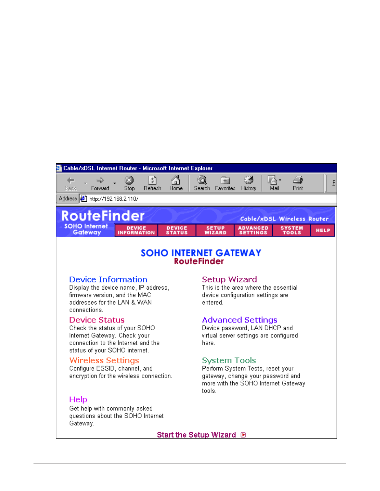
Using a Web Browser to Configure Your RouteFinder
Launch your Web browser and type the device IP address (http:// 192.168.2.1) in the
browsers address box. This IP address is the default value of your gateway. Press Enter.
Note: Please make sure your PCs address is in the same network as the routers. In
Windows 95/98/Me you can type WINIPCFG. In Windows 2000/NT, you can type IPCONFIG.
The main menu will appear. It displays all of the functions that you can browse, as well as
setup for the home Internet gateway.
Navigating - When you click one of the menu buttons at the top of the RouteFinder screen
(Device Information, Device Status, Setup Wizard, Advanced Settings, System
Tools, and Help), the corresponding screen displays. Each screen has a submenu accessed
by buttons on the left side of the screen.
Multi-Tech Systems, Inc. RouteFinder RF802EW User Guide
25
Page 26
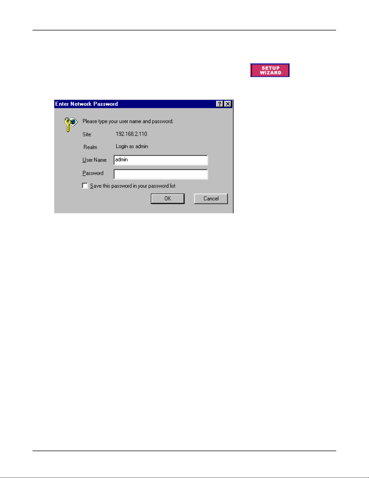
Setup Wizard
Use the Setup Wizard for a step-by-step process that lets you input all of the basic
settings to configure your Router. Click the Set Wizard button.
The Enter Network Password dialog box displays. Type admin (the default user name)
in the user name box and leave the password box empty. Click OK.
Chapter 4 - Web Browser Configuration and Management
Note: If you would like to change the password, click the Advanced Settings button and
choose Administrative Settings.
The Setup Wizard screen then displays.
Multi-Tech Systems, Inc. RouteFinder RF802EW User Guide
26
Page 27
Setup Wizard Screen
Chapter 4 - Web Browser Configuration and Management
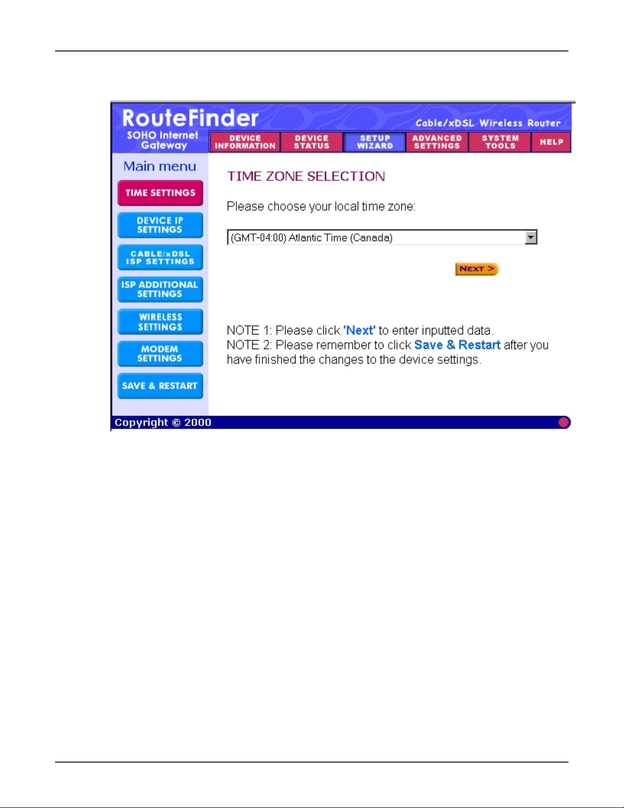
Setup Wizard - Time Settings
Choose the local time zone (see screen above). After selecting, click the Next button to
continue to the next step. You can also click the buttons on the left to continue the setup in
the order you would like.
Multi-Tech Systems, Inc. RouteFinder RF802EW User Guide
27
Page 28
Chapter 4 - Web Browser Configuration and Management
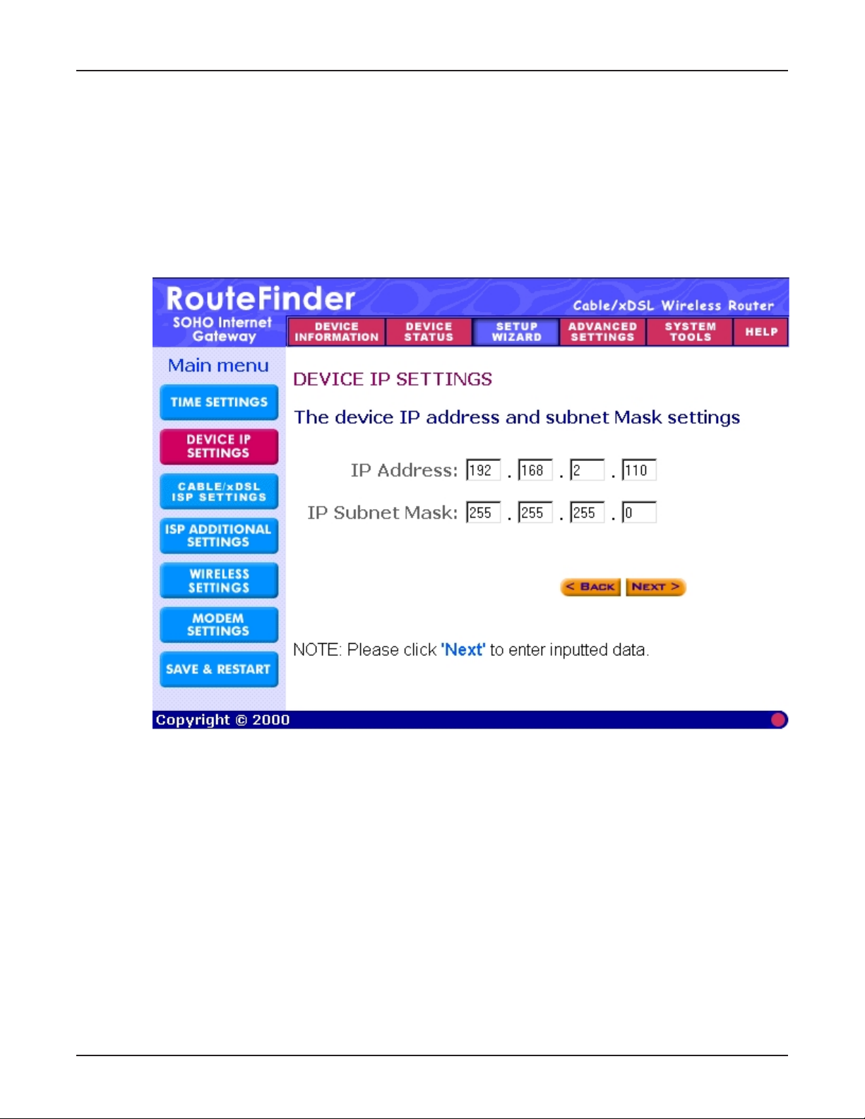
Setup Wizard - Device IP Settings
You must give your Internet gateway an IP address on your network. This is not the IP
address from your ISP but the local internet LAN IP address. The IP address 192.168.2.1
is the default value of your RF802EW.
Device IP Address
The internal LAN IP address of your Internet gateway.
Device IP Subnet Mask
The subnet mask can usually be left as its default entry 255.255.255.0.
Multi-Tech Systems, Inc. RouteFinder RF802EW User Guide
28
Page 29
Chapter 4 - Web Browser Configuration and Management
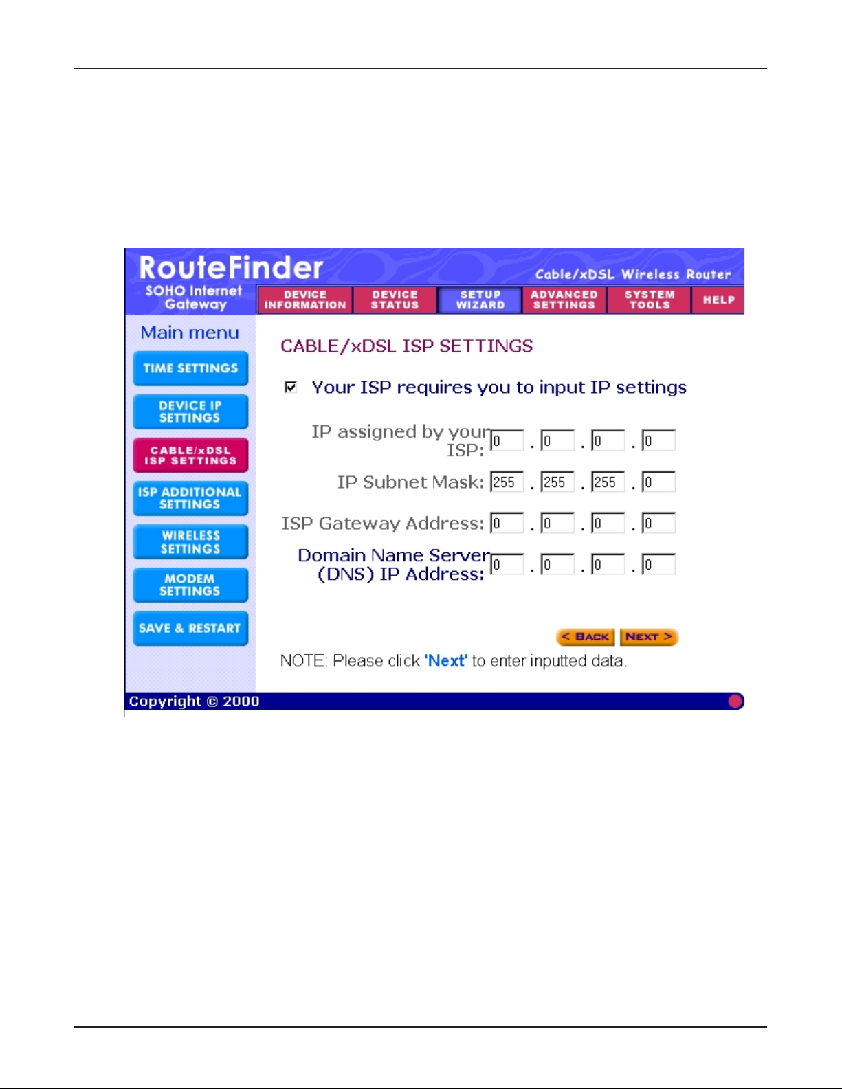
Setup Wizard - ADSL/Cable ISP Settings
If you would like to use ADSL/Cable ISP settings, you have to enable this function by
configuring this page. Some ISPs may give you Static IP settings. If this is the case for
your ISP, then you need to:
Enter the IP address that is assigned by your ISP.
Enter the IP subnet mask.
Enter the ISP gateway address.
Enter the DNS IP address.
Multi-Tech Systems, Inc. RouteFinder RF802EW User Guide
29
Page 30
Chapter 4 - Web Browser Configuration and Management
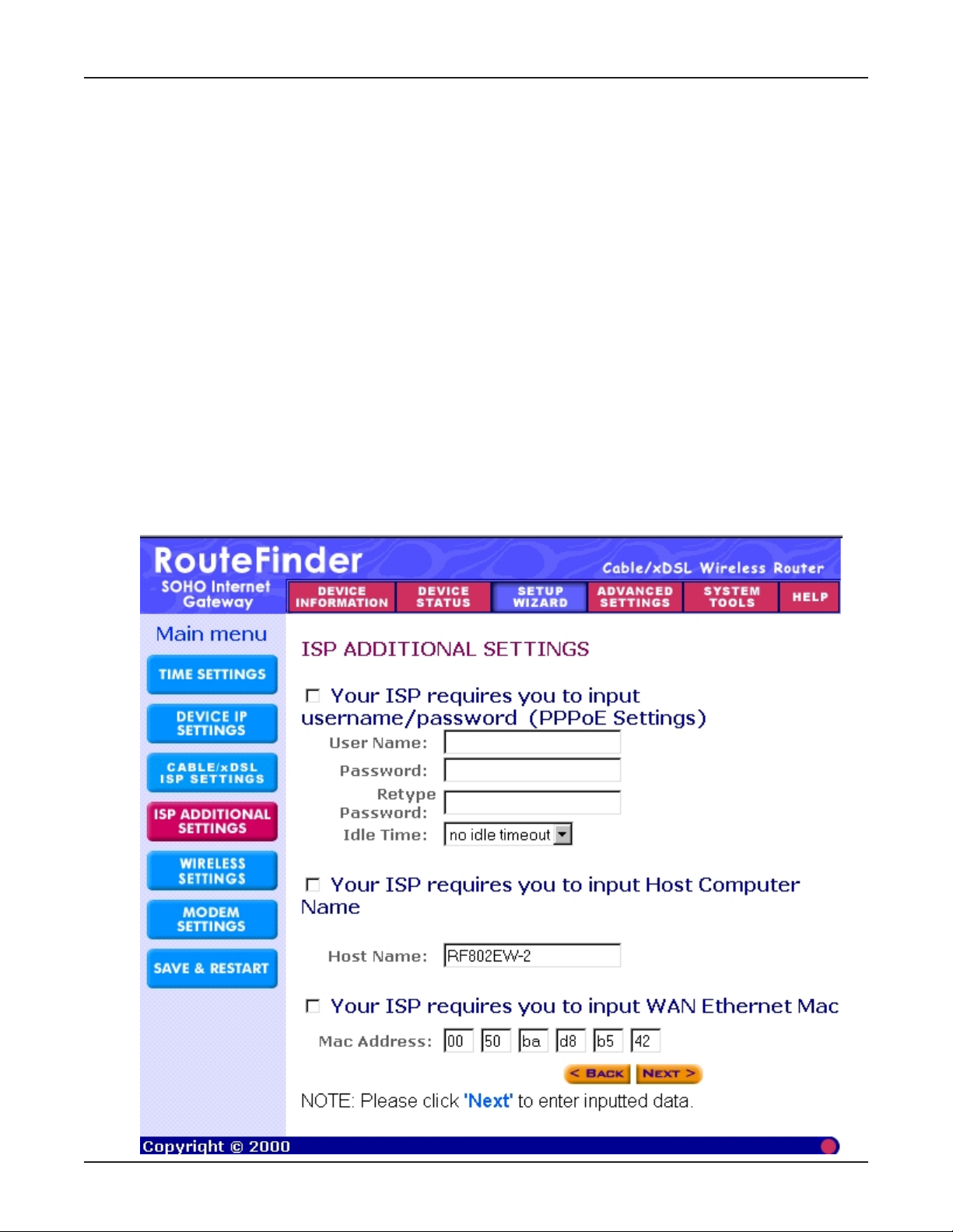
Setup Wizard - ISP Additional Settings (PPPoE Settings)
If you would like to use additional ISP settings, you have to enable this function and
configure this page. Some ISPs use this protocol for authentication purposes; if this is the
case, you need to enter:
User name: Enter the user name of your ISP account.
Password: Enter the password of your ISP account.
Retype password: Enter the password of your ISP account again to re-confirm.
Idle Time: Select the desired idle time: 5, 10, 15, 30, 60, 90, 120 minutes or no idle
timeout.
Some ISPs use a Host Name to authenticate the user; if this is the case, you need to enter:
Host Name: Enter the name of the gateway.
Some ISPs require you input the LAN card MAC address; if this is the case, you need to
enter:
MAC Address: Enter this LAN cards MAC address.
Note: Some ISPs may recognize your LAN card MAC address as a legal user. In this case,
you have to copy the LAN card MAC address in the MAC address field.
For Windows 95/98, you can run winipcfg to see the LAN card MAC address.
For Windows 2000/NT, you can run ipconfig/all to see the LAN card MAC address.
Multi-Tech Systems, Inc. RouteFinder RF802EW User Guide
30
Page 31

Chapter 4 - Web Browser Configuration and Management
Setup Wizard - Wireless Settings
Use the Wireless Settings screen to enter an ESSID, a channel, and an additional measure
of security through the use of encryption.
ESSID - Type a name that you would like to use to identify your secure shell. All wireless
work stations must use the same ESSID.
Channel - Select a channel. You may have to try more than one to achieve the best
reception.
No Encrytion - Selecting this will disable WEP encryption.
64-Bit and 128-Bit Encryption Keys - Enter a valid number for the encryption keys.
Valid entries can use digits 0-9 and letters A-F. An encryption key composed entirely of
zeroes is not allowed.
Note: These keys have to match the ones at the other location.
Multi-Tech Systems, Inc. RouteFinder RF802EW User Guide
31
Page 32

Chapter 4 - Web Browser Configuration and Management
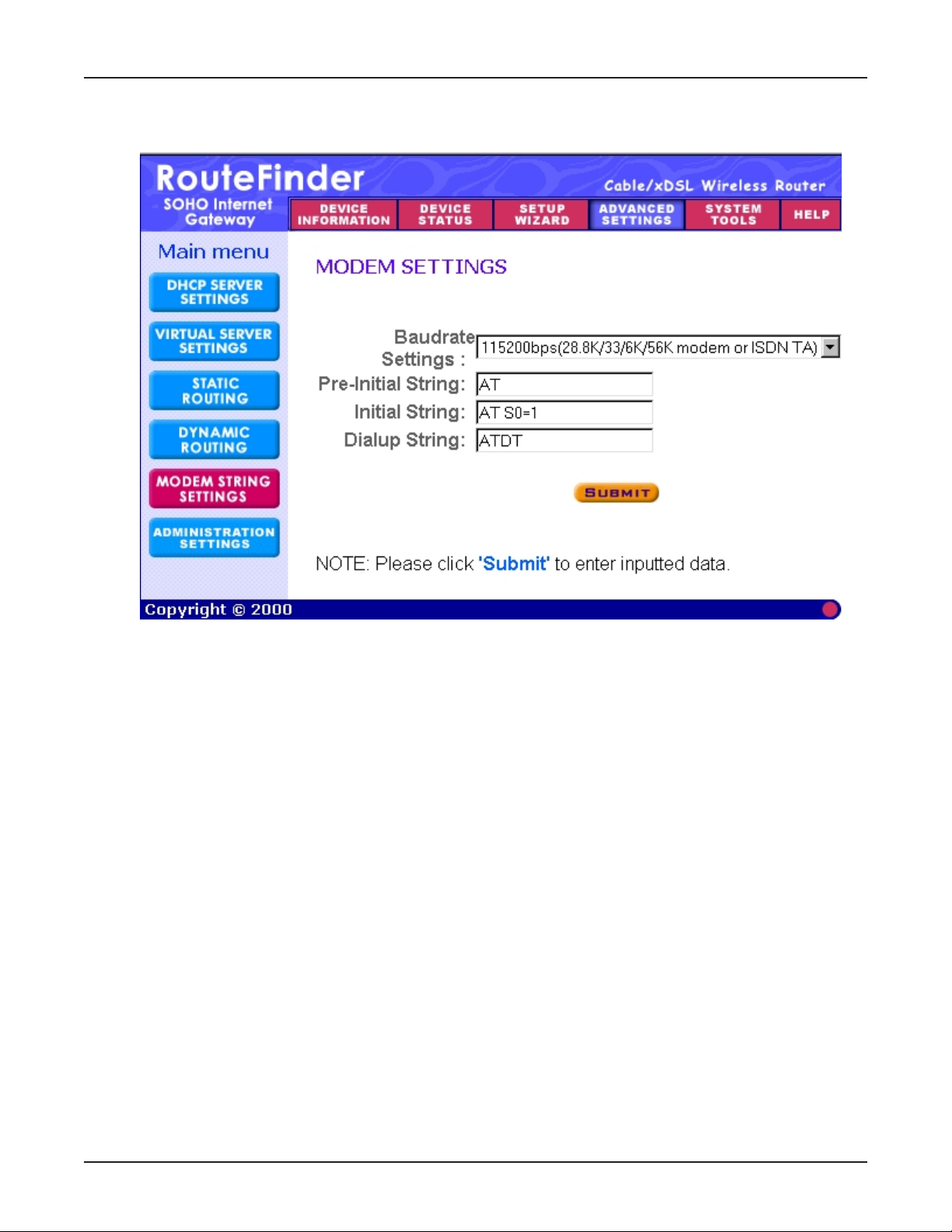
Setup Wizard - Modem Settings
The modem can be used as a dialup backup to the ADSL/Cable connection. If you would
like to use modem backup, you need to enable the modem settings function. Check the box
Dialup Modem When Cable/XDSL is not connected and input the ISP account settings.
Note: If you change the baud rate settings, please check the initial string. You can refer to
your modem manual or TA (Terminal Adapter).
Setup Wizard - Save and Restart
After you have finished making all the changes on the various pages, click Save & Restart
to save the settings and restart the device. After the restart, the device will function
according to the saved settings.
During the save and restart process, system messages will let you know that you have
successfully configured the settings for the device and saved the settings.
During the startup process, the LED of the device will blink. Please wait until the blinking
of the device stops before proceeding.
Multi-Tech Systems, Inc. RouteFinder RF802EW User Guide
32
Page 33

Device Information
Click the Device Information button when you want to review the device name, IP
address, firmware version, and the MAC address for the LAN and WAN connections.
Chapter 4 - Web Browser Configuration and Management
Multi-Tech Systems, Inc. RouteFinder RF802EW User Guide
33
Page 34

Device Status
Click the Device Status button when you want to display the current connection status of
the Internet gateway.
Chapter 4 - Web Browser Configuration and Management
Modem Backup
The modem can be used as a dialup backup to the ADSL/Cable connection.
If the current connection is modem, it will indicate Modem:Active. Otherwise, it will
indicate Not Active.
Device IP
This shows the Device IP address, private LAN MAC address, and public WAN MAC address
of the home Internet gateway.
DHCP Log
When you click the DHCP Log button, the Device IP information displays at the bottom of
the screen.
Multi-Tech Systems, Inc. RouteFinder RF802EW User Guide
34
Page 35

Advanced Settings
The Advanced Settings screen allows you to set the DHCP server settings,virtual server
settings, and password settings.
After clicking the Advanced Settings button, the Password dialog box opens. Type admin
in the user name box. If you left the password field blank, you do not have to type a
password.
Advanced Settings - DHCP Server Settings
The home Internet gateways DHCP server is enabled by default. If you would like to
disable it, uncheck the Enable DHCP Server Functions box.
Chapter 4 - Web Browser Configuration and Management
IP Address Pool Range
The IP address pool contains the range of the IP addresses that will automatically be
assigned to the clients of your network. The default setting is 192.168.2.2 to
192.168.2.100.
IP Address Reservation
You can use the IP address reservation option to give particular computers on your network
the same static IP address every time the computer is turned on.
Multi-Tech Systems, Inc. RouteFinder RF802EW User Guide
35
Page 36

Chapter 4 - Web Browser Configuration and Management
Advanced Settings - Virtual Server Settings
Virtual Server Settings allow clients on the Internet to access your LAN via the Internet.
You can use the IP mapping function to access an FTP server or Telnet server, etc. on your
LAN via your ISP Internet connection. In the Service field, type the port number.
Multi-Tech Systems, Inc. RouteFinder RF802EW User Guide
36
Page 37

Chapter 4 - Web Browser Configuration and Management
Advanced Settings - Static Routing
Routing is the process of moving a packet of data from source to destination. Use this
screen to create a routing table to connect your network to another or to connect subnets
within your network.
Enter the routing information, and then click the Add button. The routing information will
display on the lower portion of the screen. When you have completed the table, click the
Submit button.
Multi-Tech Systems, Inc. RouteFinder RF802EW User Guide
37
Page 38

Chapter 4 - Web Browser Configuration and Management
Advanced Settings - Dynamic Routing
Dynamic Routing is disabled when Static Routing is used. You will have to disable Static
Routing in order to choose one of the dynamic routing protocols (routing protocols that
adjust automatically to the changes in the network topology or traffic).
Multi-Tech Systems, Inc. RouteFinder RF802EW User Guide
38
Page 39
Chapter 4 - Web Browser Configuration and Management
Advanced Settings - Modem String Settings
Use the Modem String Settings screen to set the baud rate and any special commands.
Multi-Tech Systems, Inc. RouteFinder RF802EW User Guide
39
Page 40

Chapter 4 - Web Browser Configuration and Management
Advanced Settings - Administrative Settings
Use the Administration Settings screen to change password settings, port numbers, remote
user configuration, and system log settings.
Multi-Tech Systems, Inc. RouteFinder RF802EW User Guide
40
Page 41

System Tools
Use the System Tools screen to view the Intruder Detection Log, view the Routing Table,
and run a System Diagnosis.
System Tools - Intruder Detection Log
The event messages show the possible hacker attacks that have occurred on your Internet
gateway. Up to 32 hacker attacks may be logged in this manner.
Chapter 4 - Web Browser Configuration and Management
Multi-Tech Systems, Inc. RouteFinder RF802EW User Guide
41
Page 42

Chapter 4 - Web Browser Configuration and Management
System Tools - Display Routing Table
Use this screen to view the current routing information.
Multi-Tech Systems, Inc. RouteFinder RF802EW User Guide
42
Page 43

Chapter 4 - Web Browser Configuration and Management
System Tools - System Diagnosis
Use the System Diagnosis screen to view your Internet gateways information. This
information can help you check-up on your Internet gateway to make sure that everything
is functioning properly or, under the diagnosis section, to check the device and the link
status to see that its working.
Multi-Tech Systems, Inc. RouteFinder RF802EW User Guide
43
Page 44

Chapter 4 - Web Browser Configuration and Management
System Tools - Load Default Settings
Use this screen to load the original default settings of your Internet gateway.
Multi-Tech Systems, Inc. RouteFinder RF802EW User Guide
44
Page 45

Chapter 4 - Web Browser Configuration and Management
System Tools - Upgrade Firmware
Use this screen to upgrade the newest firmware to your RF802EW at MultiTech.com
Multi-Tech Systems, Inc. RouteFinder RF802EW User Guide
45
Page 46

Chapter 4 - Web Browser Configuration and Management
System Tools - Reset Device
Use this screen to reset your RouteFinder. Reset you RouteFinder when changing settings.
Resetting the RouteFinder will restart it. Click the Start button to reset the device.
Multi-Tech Systems, Inc. RouteFinder RF802EW User Guide
46
Page 47

Chapter 5
Telnet
Page 48

Chapter 5 - Telnet
Chapter 5 - Using Telnet to Configure Your RouteFinder
Telnet is a telecommunications software utility which allows you to access a remote device.
The RouteFinder RF802EW has a built-in Telnet Server that enables a Telnet client to
remotely configure the device using a menu system.
Important: Non-Windows operating system users must use the Telnet menu system to
define the function of the WAN and async ports, to define how IP addresses are
administered, to configure IP addresses on your local and remote systems and to set up
any necessary virtual server, routing table and packet filtering options.
Note: To successfully configure your router using Telnet, TCP/IP must be correctly
configured on your computer. The router and computer must also be located on the same
subnet.
Starting a Telnet Session
1. Start your telnet session and connect to the RouteFinder RF802EW using the
routers default IP address of 192.168.2.1 and vt100 terminal emulation.
If you are using a graphical interface such as the one shown above, click Connect.
2. When prompted to input the Router Password, press Enter.
3. The RF802EW Telnet Server Menu displays.
Multi-Tech Systems, Inc. RouteFinder RF802EW User Guide
48
Page 49

Chapter 5 - Telnet
To use the menu, type the letter corresponding to the parameter youd like to
change.
Depending on the parameter you are changing, you are presented with an open field
into which you may type new information, or you are presented with a list of options
from which you may select a value. Each menu item is described in the following
pages.
Note: After entering parameters for all settings that you want to change, continue
to type q to return to the previous menu until you reach the main Telnet Server
menu. Select Save and Restart Server to save your new configuration.
Server Menu Options
a). Router IP Address
Enter the IP address assigned to the RF802EW on your local network. The new address will
take effect after you have selected Save and Restart Server.
b). Router Subnet Mask
Enter the subnet mask for your local network.
c). Router Name
Enter a network name for the RF802EW. If your ISP requires your device to have a name,
you may use the value entered in this field.
d). Router Password
The default is no password. If you choose to use a password, ensure that you write the
password down and keep it in a safe place. If you forget the password, contact the MultiTech Technical Support for assistance. Refer to Chapter 10 in this User Guide for contact
information.
e). WAN Ethernet MAC Addr.
Displays the current MAC address of your router. Edit this only if required by your remote
system or ISP.
f). WAN Ethernet Settings
Define the function of the WAN port by selecting Internet Access (IP Routing-NAT Enabled)
or LAN-to-LAN access (IP Routing-NAT Disabled). Refer to the WAN Ethernet Segment
section of the RouteFinder Manager chapter for more information.
Internet Access
If you use the WAN port for Internet Access, you must configure the following options:
Enter the IP port information provided by your ISP or other external network administrator.
Multi-Tech Systems, Inc. RouteFinder RF802EW User Guide
49
Page 50

Chapter 5 - Telnet
Note: If your ISP uses dynamic IP addressing, leave the External Port IP address and
External Gateway IP address at the default values of 0.0.0.0. Set the External IP Netmask to
the default value of 255.255.255.0.
LAN-to-LAN Access
To use the WAN port to connect to another LAN, you must configure the following:
Enter the IP and Netmask address of the network to which you are connecting.
g). Async Port Settings
The async port may be used for IP Routing or Remote Access. For more information,
see the Async Port section of the RouteFinder Manager chapter.
IP Routing
If you will use the async port for IP Routing, enter the following information as
described:
Telephone Number
Enter the phone number the async device must dial to connect to the remote system.
User Name
Enter the User Name that will be used for authentication on the remote system.
Password
Enter the Password associated with the User Name for the remote system.
Idle Timeout
Enter the amount of idle time allowed to pass before the connection times out. The default
value is 5 minutes.
Serial Baudrate
Use the list to select the appropriate baudrate of the modem attached to your async port.
You may need to select a lower speed to ensure a quality connection.
Modem Pre-Initial String
Consult your modem or ISDN TA User Guide for this information. The default value will work
for most analog modems.
Modem Initial String
Consult your modem or ISDN TA User Guide for this information.
Modem Dialup String
Consult your modem or ISDN TA User Guide for this information.
Modem Hangup String
Consult your modem or ISDN TA User Guide for this information.
Multi-Tech Systems, Inc. RouteFinder RF802EW User Guide
50
Page 51

Chapter 5 - Telnet
Login Script
Select Enable or Disable.
Edit login Script
Refer to the RouteFinder Manager chapter of this User Guide for information on editing
scripts.
External IP Address
Enter the IP address of the remote device to which you are connecting.
NAT Function
Select Enable or Disable. Refer to the Glossary in this User Guide for additional information
on NAT.
Assign Remote IP
Select Enable or Disable. If you select Enable, you will be prompted to enter an address to
be assigned to the remote system.
Remote Access
To configure the async port for Remote Access, enter values for each of the following:
IP Assigned Method
Select the method the client will use to have their IP address assigned.
Protocols
Default value is Both IP and IPX enabled. You may select to use only one protocol,
however if you are connecting to a Netware server, you must have IPX enabled.
IPX/SPX Frame Type
The default value is Autodetect. If you have problems with your network connection, you
may select Ethernet_II, Ethernet_802.3, Ethernet 802.2 or Ethernet_snap.
Authentication Method
Select either None, PAP or CHAP. Refer to the RouteFinder Manager chapter of this User
Guide for additional information.
Edit User Database
To add users to the database, select the next available letter. Enter the User Name,
Password and Callback type for each user that you add to the database. You may enter up to
64 remote clients.
Idle Timeout
The default value is 5 minutes.
Serial Baudrate
Select one of the available options. You may need to use a slower speed to ensure a quality
connection.
Modem Pre-initial string
Refer to your modem or ISDN TA User Guide for information. The default value will work for
most analog modems.
Multi-Tech Systems, Inc. RouteFinder RF802EW User Guide
51
Page 52

Modem Initial string
Refer to your modem or ISDN TA User Guide for information.
Modem Dialup string
Refer to your modem or ISDN TA User Guide for information.
Modem Hangup string
Refer to your modem or ISDN TA User Guide for information.
Edit login script
Select this option to edit the login script executed when the client connects to the network.
Refer to the RouteFinder Manager chapter of this User Guide for additional information about
creating and editing scripts.
RADIUS Server
Select Enable to configure remote users to authenticate on a RADIUS Server.
RADIUS Access Server IP
Enter the IP address of the RADIUS Access server.
RADIUS Accounting Server IP
Enter the IP address of the RADIUS Accounting server. In most configurations, the Access
and Accounting server are located on the same machine, so the IP address is the same for
both.
RADIUS Secret
Enter the secret code or password for the RADIUS Server.
h.) Wireless Settings
Enter an ESSID, select a channel, and set encryption keys on this screen.
ESSID
Type a name that you would like to identify your secure shell. All wireless work stations must
have the same ESSID.
Channel
Select a channel. You may have to try more than one to achieve the best reception.
Enable/Disable
Choose to enable or disable WEP encryption.
WEP Keys
If you enable WEP encryption, you enter 64-bit encryption keys and 128-bit encryption keys.
Valid entries can use digits 0-9 and letters A-F. An encryption key composed entirely of zeros
is not valid.
Note: The keys have to match at both locations.
Chapter 5 - Telnet
i). Router DNS IP Address
Enter the IP address of your Internet Service Providers DNS server.
j). DHCP Server
You may select Disable or Enable. If you would like the RF802EW DHCP server function to
provide IP information to workstations as they connect to the network, select Enable.
When you enable DHCP, you will be prompted to provide the beginning and ending IP
addresses in the range of addresses administered by your RouteFinder. Refer to the LAN
DHCP section of the RouteFinder Manager chapter of this User Guide for additional
information.
k). Virtual Server
Select Disable or Enable. If you select Enable, you may enter the external and internal IP
Addresses necessary to allow remote clients to access specific devices on your network via
the Internet. Refer to the General Settings section of the RouteManager chapter in this
User Guide for more information about Enabling IP Mapping.
Multi-Tech Systems, Inc. RouteFinder RF802EW User Guide
52
Page 53

Chapter 5 - Telnet
l). Routing Table
The Routing Table option lets you create a routing table so your RouteFinder will route IP
packets to the proper network. For more information, refer to the Routing Table section of
the RouteFinder Manager chapter of this User Guide.
m). Client Filter Settings
The Filter Settings option allows you to define which packets are allowed to either pass
through, or be blocked from passing through the RF802EW ports. You may filter packets
for network services including Mail, WWW, FTP, Telnet and News. See the Filter Settings
section of the RouteFinder Manager chapter for more information about filtering options.
n). Load Default Settings
Use this option to return the router to the factory default settings.
o). Save and Restart Server
This option saves your RouteFinder configuration into Flash memory and restarts the device
to enable the settings to take effect. The system will pause while settings are being saved.
Note: After completing your configuration, you must select Save and Restart Server or
your settings will be lost when power is turned off for the device.
p). Diagnostic
The Diagnostic option performs basic testing of the RouteFinder, displays information about
your firmware and offers options for assigning the LAN and WAN MAC addresses as may be
required by your ISP.
Type any key to return to the main menu.
q). Quit
Multi-Tech Systems, Inc. RouteFinder RF802EW User Guide
53
Page 54

Chapter 6
RouteFinder Manager
Page 55

Chapter 6 - RouteFinder Manager
Chapter 6 - RouteFinder Manager
Accessing the RouteFinder Manager Software
RouteFinder manager is the main program used to configure all the settings of your
RF802EW.
1. To run RouteFinder Manager, double-click the RouteFinder Manager icon on your
desktop, or click Start | Programs | RouteFinder Manager | RouteFinder
Manager.
2. The Manager dialog box displays.
3. The RF802EW automatically searches your network for devices available for
configuration and displays them in the Available Devices list box.
Select the device you are attempting to configure from the Available Devices list.
If you need to update the list, click Refresh Device List. You must exit
RouteFinder Manager before using the device.
After you have selected a device from the Available Devices list, the Status box at
the top of the screen provides the following information about your device: name, IP
address, MAC address, and firmware version number of your RouteFinder.
Multi-Tech Systems, Inc. RouteFinder RF802EW User Guide
55
Page 56

Chapter 6 - RouteFinder Manager
Description of the RouteFinder Manager Main Screen
Buttons on the Left Side of the Screen
The buttons in the left column offer the ability to change the devices name and password,
save and load settings, upgrade the firmware or run general diagnostics on the device.
Available Devices
The RF802EW automatically searches your network for devices available for configuration
and displays them in the Available Devices list box.
Refresh Device List
If a device does not appear in the list, click Refresh Device List again to determine if the
device will appear on the list. If the device still does not appear, ensure that all cables are
correctly connected and that the power to the RF802EW is turned on. If the device still
does not appear in the list, refer to the Troubleshooing chapter of this User Guide.
Device Name and Password
You may use the default device name or use this dialog box to change the name or add a
password for your device.
Device Name - Displays the name of your network device. To change the name,
simply enter a new name. If you are connecting to an ISP via cable modem or DSL,
and your ISP requires you to enter a computer name, you may use the device name
that you entered here.
Domain Name - Enter your local network domain name.
Device Password -The RouteFinder manager does not come with a default password.
If you enter a password, you will be prompted to enter the password each time you
want to configure your network device. To enter a Password, type your password in the
Device Password box, then re-enter your password in the Password Verification
box.
Note: Entering a password is strongly recommended to protect your RouteFinder from
unauthorized reconfiguration. If you enter a password, ensure you have selected
something that will be easy to remember or write it down and store it in a safe location.
If you have completely forgotten your password, contact Multi-Tech Technical Support
for assistance. Refer to Chapter 10 in this User Guide for more information about our
Technical Support services.
Multi-Tech Systems, Inc. RouteFinder RF802EW User Guide
56
Page 57

Chapter 6 - RouteFinder Manager
Save Settings to File
This option allows you to save your settings to a file. This option provides a method for
backing up your system configuration so that it can be used in the event your settings
become accidently deleted. This option can also be used if you would like to have more
than one set of settings for your RouteFinder.
1. From the main Manager dialog box, click Save Settings to File.
2. The Save Settings to File dialog box displays.
3. In the File Name box, enter the full path of the file containing the settings you
want to use or click
of the file in a different location by changing the path.
4. Click OK to save the settings to the file.
then navigate to and select the file. You can save a copy
Load Settings
This option allows you to load either the default settings of your network device or to load
settings previously saved to a file.
1. From the main Manager dialog box, click Load Settings.
2. The Load Settings dialog box displays.
3. To return the RouteFinder to factory default settings, select Load Default Setting.
4. To load a configuration from a file, select Load Settings From File.
5. In the File Path box, enter the name of the file containing the settings you would
like to use or click then navigate to and select the file.
6. Click OK to load and apply the settings to the RouteFinder.
Multi-Tech Systems, Inc. RouteFinder RF802EW User Guide
57
Page 58

Chapter 6 - RouteFinder Manager
Upgrade Firmware
This options allow you to upgrade your RF802EW firmware. It upgrades the firmware of
your RF802EW, not the RouteFinder Manager or Monitor software.
Warning: Upgrade the firmware of your RouteFinder RF802EW only under the advice and
direction of the Multi-Tech Technical Support Group. Improperly upgrading the RF802EW
may disable the device!
1. From the main Manager dialog box, click Upgrade Firmware.
2. The Upgrade Firmware dialog box displays.
3. Download the latest firmware from the Multi-Tech Systems web site at
www.multitech.com.
4. Copy the firmware to the directory containing the RouteFinder Manager program
files. Refer to the default Firmware File Directory box to determine the location of
the files on your system.
5. Enter the location of the new firmware file in the Firmware File Directory box.
RouteFinder Manager will automatically detect the new firmware file name and
display it in the Firmware File Name box. The version number of your firmware
will display in the Firmware File Version box.
6. Click Upgrade to upgrade your firmware.
7. A message displays stating the upgrade has started.
8. After several minutes, an informational dialog box displays indicating the upgrade
was successful.
9. Click OK.
10. From the main Manager dialog box, click Save and Exit.
11.Click Yes to restart the RouteFinder using the new firmware version.
Multi-Tech Systems, Inc. RouteFinder RF802EW User Guide
58
Page 59

Chapter 6 - RouteFinder Manager
General Diagnostic
This option displays network device information and allows you to determine if the
RF802EW is functioning properly.
1. From the main Manager dialog box, click General Diagnostic.
2. The General Diagnostic dialog box displays information about the RF802EW.
3. Record the information if necessary and click OK to exit.
Buttons on the Right Side of the Screen
The buttons in the right column provide access to advanced configuration options for
General Settings, Port Settings, LAN DHCP Server Options, Router Settings, and Filter
Settings. These are described in detail on the following pages.
Multi-Tech Systems, Inc. RouteFinder RF802EW User Guide
59
Page 60

Chapter 6 - RouteFinder Manager
General Settings Option on the Manager Main Screen
After selecting your device from the Available Devices list, click General Settings to
view or change all of the major network settings for the RF802EW including LAN and WAN
Ethernet segment settings, DNS information, IP Routing, and Remote Access settings.
Most of the settings here were entered in Setup Wizard. However, some important settings
can be entered only in RouteFinder Manager.
This Wireless Point Settings dialog box displays first.
Enable Access Point + Router function is the default option. This allows you to setup
your network connection and routing.
If Enable Access Point function only is selected, you can set the Access Points IP as
manual settings or acquire an IP address from a DHCP server. This allows you to setup
your network connection without routing.
Click Click here to Setup Router Settings to select Router settings for your RouteFinder.
The General Settings dialog box contains settings for IP information for LAN Ethernet
Segment and WAN Ethernet Segment, DNS number, IP Routing settings, and Remote
Access settings.
Multi-Tech Systems, Inc. RouteFinder RF802EW User Guide
60
Page 61

Chapter 6 - RouteFinder Manager
General Settings Options
LAN Ethernet Segment
Server IP address - This IP address is the internal LAN IP address of the RF802EW.
The address entered into the Setup Wizard is displayed here (for example,
192.168.2.1).
Server IP Netmask -The RF802EW subnet mask generally can be left at the default
value of 255.255.255.0.
WAN Ethernet Segment
Select NAT (Network Address Translation) to provide firewall protection and enable
all local LAN users to share one IP address to access the Internet. If the NAT box is not
selected, the WAN Ethernet is configured as a router to route network traffic between
the LAN Ethernet segment and the WAN Ethernet segment. The External Port IP
Addresses are provided by your ISP or remote system administrator.
PPPoE - If your ISP uses Point-to-Point Protocol over Ethernet for authentication
purposes, select the PPPoE box and enter your ISP account User Name and Password.
External Port IP Address - Enter the IP address provided by your ISP or remote
system administrator.
External Port IP Netmask - Enter the subnet mask of the port as provided by your
ISP or remote system administrator.
Gateway IP Address - Enter your ISP or remote networks Gateway IP address.
Note: If your ISP uses a DHCP server to automatically assign a login IP address,
subnet mask, gateway IP address or DNS IP address, enter 0.0.0.0 as your External
Port IP Address and the Gateway IP Address.
Multi-Tech Systems, Inc. RouteFinder RF802EW User Guide
61
Page 62

Chapter 6 - RouteFinder Manager
Async Port
The Async Port can be configured to provide either IP Routing or Remote Access. IP
Routing is used to connect your network to another router through the Serial async
port. Remote Access allows remote users to dial-in to the device to access and share
network resources as if they were logged on to the network locally.
1. To configure the RF802EW for IP Routing, select IP Routing in the Async Port
section of the General Settings dialog box.
2. Click PPP Settings.
3. The IP Routing Settings dialog box displays.
IP Routing (NAT Enabled) - If NAT is enabled, all local users will be firewall
protected and will share one IP address through the Async port. Enter values in the
fields as described:
Tel Number - Enter the phone number required to access your ISP.
User Name - Enter the account user name to be authenticated by your ISP.
Password - Enter the user account password to be authenticated by your ISP.
Password Verification - Re-enter the user account password for verification.
External (Port) IP - Enter the fixed IP address provided by the remote site
System Administrator. If this address is automatically assigned by the remote site
DHCP server, enter 0.0.0.0
Assign Remote Site an IP Address - Check the box if you will specify the IP
Address of the remote site.
Remote IP Address - Enter the IP address the remote site will use.
Multi-Tech Systems, Inc. RouteFinder RF802EW User Guide
62
Page 63

Chapter 6 - RouteFinder Manager
Allow Remote Dial-In - This option allows a remote site to dial-in to this network.
1. From the IP Routing Settings dialog box, select Allow Remote Dial-In.
2. Click Remote Authentication Settings.
3. The Remote Connection Authentication dialog box displays.
4. Select one of three methods to define the authentication protocol to be used when a
remote site is dialing in to your site:
None - No authentication needed.
PAP - User Name and unencrypted Password are transmitted over the network.
CHAP - DHCP sends a key which is used to encrypt the user name and password.
Encryption provides added protection from potential interception of authentication
information.
Note: If you select PAP or CHAP, you must indicate where the authentication
process should occur, by selecting Use Local Settings, Use Local Client List, or
Use RADIUS Authentication. Refer to Remote Connection Authentication Settings
following this section.
5. Click OK when complete.
Callback Settings - From a remote site, you can trigger your RF802EW to establish a
connection with your ISP.
1. Click Callback Settings and select one of three call back options:
No Callback
Trigger (ISP) Server Connection - The RouteFinder will establish a connection
with the ISP server after a remote user dials into the asynchronous port. The
device can be triggered to automatically establish a connection with the ISP in
one of two ways:
1. The ISP server is dialed after the RF802EW receives a PPP (modem)
connection from a remote user.
2. The RF802EW makes the connection to the ISP server after receiving a
regular telephone call. The remote user calls the RF802EW async port to
trigger the connection to the ISP server.
Remote Callback - After dialing, the RF802EW hangs up and waits for the
remote site to callback. You must enter the callback telephone number (the
telephone number the device should call) in the Tel Number box.
2. Click OK to complete.
Multi-Tech Systems, Inc. RouteFinder RF802EW User Guide
63
Page 64

Chapter 6 - RouteFinder Manager
Remote Authentication Settings - When you select Allow Remote Dial-in, you must
determine the method that remote users must use to be authenticated on your system. If
you choose the PAP or CHAP authentication protocol, you must select Use Local Settings,
Use Local Client List or Use RADIUS Server authentication.
Use Local Setting - You may create a Remote User Name and Remote Password to log
in to the system. All users must type the same user name and password that you
specify.
Use Local Client List - The Local Client list is a list of all User Names and Passwords
that can access your network from a remote site. When a remote user dials in to the
RF802EW, the users access profile information (user name, password, callback status,
etc.) is validated by checking the user information in this list. The RF802EW can
include up to 64 users in the Local Client list. Click Local Client List to add your remote
users.
Important: The RF802EW is set up with a default user of guest which requires no
password. For security reasons, either delete the user ID guest or provide it with a
password.
Client Information - For each new remote user added to the system, enter the
following information:
User Name - Specify a user name with a maximum of 16 characters.
Password - Specify the password corresponding to the user name. Passwords are
limited to 16 characters.
Password Verification - Verify the password by re-entering the user password in
the box provided.
Callback Type - The callback feature provides an added level of security to your
dial in system. A remote client dials in to the network and then disconnects. The
RF802EW then calls the client back. The feature can be implemented using no
callback, fixed callback, or variable callback.
No Callback - The RouteFinder does not perform a callback function. This is the
default setting.
Multi-Tech Systems, Inc. RouteFinder RF802EW User Guide
64
Page 65

Chapter 6 - RouteFinder Manager
Fixed Callback - The RouteFinder will connect to the client by dialing the number
specified in the Your TelNumber box.
Variable Callback - This option allows the remote client to specify the phone
number the RouteFinder should callback each time a dial up connection is
established.
Assign a specific IP address for this user - Select this option if you would like to
have a specific IP address assigned to this user. Enter the IP address. This IP
address will be used each time the client logs in and will override the Assign Remote
Site an IP Address option as shown in the IP Router Setting dialog box. Click Add
to add this client to the Local Client List.
Use Radius Authentication - Choosing RADIUS Authentication allows you to use the
user information (such as user name, password, IP address) stored on a separate RADIUS
server on the network.
Note: A RADIUS Server (Remote Authentication Dial-In Service) is an accounting and
authentication system used by many large companies and Internet Service Providers
(ISPs). After a client dials into the network and enters their user name and password, the
information is passed to a RADIUS server. The RADIUS server checks that the information
is correct, and then allows access to the system.
1. From the Remote Access Settings dialog box, click Use RADIUS Authentication,
then click RADIUS Setup.
2. The RADIUS Configuration dialog box displays.
3. Use the List box to select the Main or Backup RADIUS Server from which the device
will be authenticated.
4. Enter the RADIUS Access Server IP Address and the RADIUS Accounting Server IP
Address
Note: In most cases, the RADIUS Accounting Server and the Access server are the
same device. If this is true for your configuration, enter the same IP address in
both boxes.
Secret - Enter your Shared Secret.
Secret Confirmed - Re-enter your Shared Secret.
5. Click OK when complete.
Multi-Tech Systems, Inc. RouteFinder RF802EW User Guide
65
Page 66

Chapter 6 - RouteFinder Manager
Remote Access Settings
1. From the General Settings dialog box, click the Remote Access radio button and
then click the Remote Access Settings button.
2. The Remote Access Settings dialog box displays.
Enter the following:
IP Assigned Method for Remote Clients - A remote client must have an IP
address to connect to the network. IP addresses may be assigned automatically
from a designated IP address pool using DHCP, or the IP address may be manually
assigned.
Assign an IP Address Automatically - The DHCP feature will issue the remote
site user an IP address automatically if the DHCP function is enabled. If DHCP is
disabled, the device will automatically search for a DHCP server and request an IP
address for the remote client.
Assign an IP address manually - Enter an IP address for the remote client.
Network Protocols - You must select the network protocols you would like to
enable for the dial-in service. The default enables both TCP/IP and IPS/SPX. If you
do not need both protocols, you may disable one of them. If you are connecting to
a Netware Server, IPX/SPX must be enabled.
IPX/SPX Frame Type - The RF802EW can automatically detect what kind of IPX/
SPX frame type you are using. You may manually select a frame type by using the
list box.
Multi-Tech Systems, Inc. RouteFinder RF802EW User Guide
66
Page 67

Chapter 6 - RouteFinder Manager
Remote Client Authentication - Remote authentication settings allow you to
specify how you would like to authenticate remote users. You may select Use Local
Client List or Use RADIUS Authentication (refer to Remote Connection
Authentication Settings in this chapter for more information). Choosing RADIUS
configuration allows you to use the user information (such as user name, password,
and IP address) stored on a separate RADIUS server on the network.
3. Click OK when complete.
Enable IP Mapping - Virtual Server
IP Mapping is available only when NAT is enabled. If NAT is enabled for a particular port,
that port is firewall protected. The Enable IP Mapping function allows you to open a hole
in your firewall to allow access to your LAN via the Internet. For example, you can use the
IP mapping function to access an FTP server on your LAN via the Internet. IP Mapping is
most suitable to fixed or static IP addressing.
1. To enable IP Mapping, from the General Settings dialog box, select Enable IP
Mapping, then click IP Mapping (Virtual Server).
2. The Virtual Server Mapping dialog box displays.
For each service you want to set up:
1. Select either the WAN or Async (Serial) port from the Port No list.
2. Enter the External IP address supplied by your ISP. If your ISP uses dynamic IP
addressing, enter 0.0.0.0. Your device will use the dynamically assigned address
when connecting to your ISP.
Multi-Tech Systems, Inc. RouteFinder RF802EW User Guide
67
Page 68

Chapter 6 - RouteFinder Manager
3. Enter the TCP/IP port number for the service that you will be using for IP mapping.
Common TCP/IP port numbers are listed below:
WWW Port 80
FTP Port 20 or 21
SMTP Port 25
POP3 Port 110
If you would like to map all services for this external IP address to a computer on
your LAN, you can enter port number 0. This means that whenever anyone accesses
your external IP address, they will automatically be mapped to the internal
computer that you specify, regardless of what port number they are using.
4. Enter the Internal IP address of the server to which you want to map the External IP
address.
5. Enter the port number for the service that you will be using for this IP mapping.
Click Insert to include the mapping.
6. Click OK when you have completed mapping addresses.
Note: IP Mapping function allows you to have only one port service on your LAN.
For example, if you map an external IP (16.895.1.3) to an internal IP address
(192.168.2.22 - a www server), only the internal IP address in your local network
can serve as the www.server for the external IP address.
Multi-Tech Systems, Inc. RouteFinder RF802EW User Guide
68
Page 69

Chapter 6 - RouteFinder Manager
Port Settings Option from the Manager Main Screen
The Modem Settings options are used to configure the communication between your
modem or ISDN TA and your RouteFinder serial port. You must specify the baudrate,
modem and modem string settings for your device.
1. To view or change the port settings, from the main Manager dialog box, click Port
Settings. The Port Settings dialog box displays.
2. Complete the following:
Baudrate - Use the list to select the Remote Access DTE speed for your device.
The absolute maximum setting for a given port on the network device is 4 x the
speed of your modem. If the baudrate is set too high, your network device may fail
to establish a dial-up connection. For example, if you have a 14.4Kbps modem, the
highest speed selected is 57.6Kbs.
If your modem does not appear in the list provided, the Standard Modem selection
will work in most cases.
Important: If you are using an ISDN Terminal Adapter, refer to the Async to Sync
PPP string in the User Manual provided with the device to determine the correct
initialization, dialup, and hang up strings.
Note: Due to variations in ISP connections and phone line quality, this theoretical
maximum speed is not attainable. You may need to set the baudrate at a lower
speed.
Multi-Tech Systems, Inc. RouteFinder RF802EW User Guide
69
Page 70

Edit Login Script for Remote Access
1. From the Port Settings, click Edit Login Script.
2. The Login Script dialog box displays.
Chapter 6 - RouteFinder Manager
A sample remote access login script is shown below. If a remote access client is
configured to bring up a terminal window after dialing, this remote access login
script initiates.
For Remote Access, the device will act as the server side...
Send Welcome! displays Welcome to remote site.
Send sends an Enter (Carriage return + line feed) to the remote site.
Send Username prompts the remote site for a user name.
Retrieve 1 will wait for the remote site to enter the user name that will be used for
PPP authentication.
Send Password prompts the user for a password.
Retrieve 2 will wait for the remote site to enter a password.
Verify 3 instructs the device move to login script line 3 if PPP authentication fails.
Go means start PPP protocol.
Multi-Tech Systems, Inc. RouteFinder RF802EW User Guide
70
Page 71

Chapter 6 - RouteFinder Manager
Writing a Login Script for IP Routing
To write an effective login script, you must obtain the correct login script information
from your ISP and become familiar with using the login script commands.
Every ISP has a unique login interface screen. Check with your ISP to determine how
your ISP requests information from you when using a PPP connection.
Note: You can create a simple dial-up connection to view your ISP interface log-in
screen using Dial-Up Networking in Windows 95, 98, NT or 2000.
Some common commands are:
Send and SH FUNCTION
Send ATZ Resets the Modem
Send ATDT 888-1234 Dials the phone number 888-1234
Send JaneDoe Types JaneDoe at the ISP interface
SH 1234 Types 1234 at the ISP interface but displays **** on
the RouteFinder monitor to hide the password.
Send Sends Enter (carriage return plus line feed) to the ISP
Wait FUNCTION
Wait 5 The Modem will wait for 5 seconds before moving to the
next line in the login script.
Wait CONNECT The Modem will wait for CONNECT to display before
moving to the next command.
Wait CONNECT 6 Modem will wait for CONNECT to display before
moving to the next command. If CONNECT does not
display, the modem will go to line 6 of the login script.
Other FUNCTION
Go Begins PPP
Jump4 Goes back to line 4 of the login script.
Hangup Hangs up the modem.
Example 1: Script for Normal Reliable ISP
# Login Script Meaning of Each Login Script Command
1 SendATZ Rests Modem
2 SendATS0 =1 Sends initial string ATS0 =1 to modem
3 SendATDT888-1234 Dial phone number 888-1234
4 WaitCONNECT Waits for ISP to send reply CONNECT
5 Waitusername: Waits for ISP to send reply username
6 SendJaneDoe Sends the user name JaneDoe to the ISP
7 Waitpassword Waits for ISP to send reply password
8 SH1234 Sends password 1234 to the ISP
9 Wait===> Waits for ISP to send reply ===>
10 Send1 Selects option 1 (PPP) for this ISP
11 Go Starts PPP mode
Example 2 : Script for Unreliable ISP (Redial until connected)
# Login Script Meaning of Each Login Script Command
1 SendATZ Resets Modem
2 SendATS0 =1 Sends initial string ATS0 =1 to modem
3 SendATDT8881234 Dials phone number 888-1234
4 WaitCONNECT2 Wait for ISP to send reply CONNECT. If no
CONNECT, returns to line 2 to re-dial.
5 Waitusername:12 Waits for ISP to send reply username. If no
response, goes to line 12.
Multi-Tech Systems, Inc. RouteFinder RF802EW User Guide
71
Page 72

Chapter 6 - RouteFinder Manager
6 SendJaneDoe Sends the username JaneDoe to the ISP
7 Waitpassword Waits for ISP to send reply password
8 SH1234 Sends password 1234 to ISP
9 Wait====> Waits for ISP to send reply ===>
10 Send1 Selects option 1 (PPP) for this ISP
11 Go Starts PPP mode
12 Hangup Hangs up Modem
Example 3 : Script for Unreliable ISP (2nd ISP backup)
# Login Script Meaning of Each Login Script Command
1 SendATZ Resets modem
2 SendATS0 =1 Sends initial string ATS0 =1 to modem
3 SendATDT8881234 Dials phone number 888-1234
4 WaitCONNECT 12 Waits for ISP to send reply CONNECT. If no reply,
goes to line 12 for ISP #2.
5 Wait username: 12 Waits for ISP to send reply username. If no
response, goes to line 12 for ISP #2.
6 SendJaneDoe Sends the username JaneDoe to ISP
7 Waitpassword Waits for ISP to send reply password
8SH1234 Sends password 1234 to ISP
9 Wait====> Waits for ISP to send reply ===>
10 Send1 Selects option 1 (PPP) for this ISP
11 Go Starts PPP mode (Rest of script ignored)
12 Hangup Hangs up Modem
13 Send AT S0=1 Sends initial string AT SO=1 to modem
14 Send ATDT 8885678 Dials phone number 888-5678 (ISP #2)
15 Wait Connect 23 Waits for ISP to send reply CONNECT. If no
CONNECT, goes to line 23.
16 Wait username: 23 Waits for ISP to send reply username. If no
response, goes to line 23.
17 Send Stephen Sends the username Stephen to ISP
18 Wait password: Waits for the ISP to send password:
19 SH 5678 Sends password 5678 to ISP
20 Wait====> Waits for ISP to send reply ===>
21 Send1 Selects option 1 (PPP) for this ISP
22 Go Starts PPP mode
23 Hangup Hangs up Modem
24 Jump 2 Goes back to line 2 to re-dial ISP #1
Modem String Settings - The most important modem string is the initialization string
because your network device uses it to establish communications with your modem or
ISDN TA. The modem initialization string displayed is the modem or ISDN TA initialization
string entered in the Setup Wizard. For most analog modems, the Standard Modem
selection will work. For additional information, refer to the Modem Settings information
presented in the Software Installation and Configuration Chapter of this User Guide.
Important: There is no standard ISDN TA initialization string. If your ISDN TA is not
included in the modem list, check your ISDN TA Users Guide for information for the
initialization string for an Asynchronous to Synchronous PPP connection. If you are using
only one channel of your ISDN connection, you can enter the Async to Sync PPP
initialization string. If you are bundling your connection channels, use a Multilink-PPP
initialization string. You must also enter the two phone numbers in the Telephone
Number box of the General Settings dialog box. Also verify that your ISDN TA supports
the dial-up string ATDT. Most ISDN TAs support ATDT, but some support ATD or ATDI.
Multi-Tech Systems, Inc. RouteFinder RF802EW User Guide
72
Page 73

Chapter 6 - RouteFinder Manager
Dial-up/Hang-up Settings - The Dial-up/Hang-up settings allow you to specify your
connection time (idle timeout or auto reconnect) and the number of times to attempt to
connect if a connection cannot be established.
1. From the main Manager dialog box, click Port Settings.
2. Click Dial-up/Hang-up Settings. The Dial-up/Hang-up Settings dialog box
displays.
Individual Port Options - Individual Port Options lets you set the idle-timeout
function for each serial port of the RouteFinder. You can set the number of minutes you
wish to allow a connection to stay idle before disconnection.
Note: Default idle timeout for IP Routing is 5 minutes. Default idle timeout for Remote
Access is 30 minutes.
If you un-check the idle-timeout, once a client establishes a connection, the
connection will be maintained until you turn off your modem, unplug your network
device or use the Terminate Connection function in the RouteFinder monitor program.
The Automatic Reconnect (Always connect) essentially maintains your connection (idle
time out = infinite). If the connection is disconnected for any reason, it will
automatically attempt to reconnect.
Dial-up Retry Options - The Dial-Up Retry option allows you to specify the number
of times the RouteFinder should attempt to establish a connection.
If the retry count is 0, the device will not dial-out to connect to the remote site.
Note: Automatic Reconnect overrides the Retry count setting if retry count is set to 0.
Multi-Tech Systems, Inc. RouteFinder RF802EW User Guide
73
Page 74

Chapter 6 - RouteFinder Manager
LAN DHCP Server Option from the Manager Main Screen
Note: Refer to the Glossary at the back of this User Guide for more information
about the DHCP function.
1. From the main Manager dialog box, click LAN DHCP Server.
Note: The LAN DHCP Server option indicates if DHCP is Enabled or Disabled. By
default the DHCP function is Enabled. To Disable the function, you must open the
DHCP Configuration dialog box, select Disabled and click OK.
2. The DHCP Configuration dialog box displays.
3. Complete the following information:
DNS IP Address - Enter the ISPs DNS IP address. You may enter up to four ISP
DNS IP addresses. Click Insert.
IP Address Pool - The IP Address Pool contains the range of IP addresses that will
be automatically assigned to the clients of your network as they connect to the
network.
Note: By default, the IP address pool range is from 100 to 200. Ranges are listed
in the IP Address Pool table.
To change the range:
1. Select the existing range of addresses.
2. Enter a new range.
3. Press Insert.
Multi-Tech Systems, Inc. RouteFinder RF802EW User Guide
74
Page 75

Chapter 6 - RouteFinder Manager
To delete an IP Address range:
1. Select the range of addresses.
2. Press Delete.
IP Address Mapping Reservation - You can use the IP Address Mapping
Reservation option to give a static IP address to particular computers on your
network. Each time a computer is powered on and connects to the network, it will
receive the same IP address. Static IP addresses are frequently assigned to network
resources such as printers, servers, hubs, and routers that are consistently shared
by network clients.
To assign a static IP Address:
Enter the MAC address manually or use the MAC address search tool.
To use the MAC address search tool:
1. Enter the IP address of the computer.
2. Click Search to find the MAC address.
3. Once the address has been located, click Add to reserve the address.
To delete a static IP Address:
1. Select the static address you would like to delete.
2. Click Delete.
Note: Refer to the User Guide Glossary for information about determining a
computers netmask address.
Multi-Tech Systems, Inc. RouteFinder RF802EW User Guide
75
Page 76

Chapter 6 - RouteFinder Manager
Routing Settings Option from the Manager Main Screen
Routing is the process of moving a packet of data from source to destination. The
RF802EW acts as a router to enable messages to pass from one computer to another and
eventually reach the target machine. Part of this process involves analyzing a routing table
to determine the best path. Use the information below to create a routing table to connect
your network to another network, or to connect subnets within your network.
Note: A routing table is required to use the LAN-to-LAN routing function of the RF802EW.
1. From the main Manager dialog box, select Routing Settings.
2. The Routing Settings dialog box displays.
Static Routing - For each different subnet on your LAN, enter:
IP - Enter the (network/subnet) IP address to which you want to route.
Netmask - Enter the subnet mask of your Network IP address.
Gateway - Enter the IP address of the gateway device linking your network to the
other network/subnet. The IP address should be in the same subnet as your RF802EW.
If you are using this device with the LAN -to- LAN function, the gateway IP should be
set as the IP address of the RouteFinder.
Interface - Select the port (LAN or WAN) that the routed packet should pass
through. Select Local Network if you are using a separate router. If you are using
the RF802EW with the LAN-to-LAN function, the Interface should be set as the WAN
port that connects you to the other subnet.
Click Insert to save the information to the routing table.
To delete this information, select it from the routing table and click Delete.
Default Gateway - Default gateway is an IP address that all packets are routed to,
when the device is unable to find a route match (the destination IP address of the
packet in the routing table).
Click Add Default Gateway to save the IP address of the default gateway.
Interface - Select the port (LAN or WAN) interface where the gateway is located.
Multi-Tech Systems, Inc. RouteFinder RF802EW User Guide
76
Page 77

Chapter 6 - RouteFinder Manager
Routing Table Example
The routing table stores the routing information so that the RF802EW knows how to route
the IP packets to the proper network.
PC 1
192.168.3.9
WAN Ethernet 192.168.3.1
RF802EW-1
LAN Ethernet 192.168.5.1
WAN Ethernet 192.168.5.254
RF802EW-2
LAN Ethernet 172.168.2.254
PC 2
172.168.2.1
What is the purpose of the routing table?
In the diagram above, the RF802EW-1 has the routing information to route between
192.168.3.x and 192.168.5.x. The device does not have the information about how
to route to the 172.168.2.x network. If you want the RF802EW-1 to route to
172.168.2.x, you must add the following information to the routing table:
IP: 172.168.2.0
Network: 255.255.255.0
Gateway IP: 192.168.5.254
Interface: Ethernet (Local Network)
If you would like the RF802EW-2. to route to 192.168.3.x, enter the following
routing table information into the RF802EW Routing settings:
IP: 192.168.3.0
Network: 255.255.255.0
Gateway IP: 192.168.5.1
Interface: WAN Ethernet
Multi-Tech Systems, Inc. RouteFinder RF802EW User Guide
77
Page 78

Chapter 6 - RouteFinder Manager
Filter Settings Option from the Manager Main Screen
You can use Filter Settings to choose which packets are allowed to enter the network and
which packets will be blocked. Filter Settings can be used to filter network services such as
Mail, WWW, FTP, Telnet and News.
1. From the main Manager dialog box, select your RF802EW, then Filter Settings.
2. The Filter Settings dialog box displays.
3. Select the Block tab or the Pass tab to define your filtering.
The Block function filters by blocking packets from going out the WAN port and
coming in through the LAN port. To enable the Block IP filter function, select
Enable Block IP Filter Function.
The Pass function filters by defining which packets can go into your WAN port and
come on to your LAN. To enable the Pass IP filter function, click the Pass tab and
select Enable Pass IP Filter Function.
Multi-Tech Systems, Inc. RouteFinder RF802EW User Guide
78
Page 79

Chapter 6 - RouteFinder Manager
4. To filter packets to be passed or blocked, use the Packets Defined by list to select
TCP/IP or User.
Packets Defined by TCP/IP - If you choose to define by TCP/IP, you must enter
the packet IP information.
IP Address - Enter the IP address of the packet to be Blocked or allowed to Pass.
Netmask - Enter the subnet mask for the packet.
TCP/IP Service Port - Enter the Socket Port you would like to block or allow to
pass (for example, HTTP= 80)
Privilege Level - Use the Privilege list box to select an appropriate level for this
filter. It is common to set many filter rules for a particular client. At times, the rules
you have set may conflict with one another. When a conflict occurs, the filter with
the higher privilege level will override the other filters.
Note: Level one is the highest level; level sixteen is the lowest privilege level.
Example: Lets say you configure a filter rule for IP address 192.168.100.72
with a privilege level of 16 to Pass using socket number 80. At the same time,
you set the same filter rule to block IP Address 192.168.100.72 with a privilege
level of one. The RF802EW will implement the filter to block the IP address
192.168.100.72 because the privilege level is higher.
Note: If conflicting rules have the same privilege level, then the RF802EW will
block the packet.
Click Insert to add each IP address to the list.
To remove a defined packet, select the packet youd like to delete from the table and click
Delete.
Packets Defined by User - If you choose to define by User, you must define the
byte pattern of the packets. The RF802EW uses the defined byte patterns to block
or pass packets from the WAN or from the LAN.
1. In the Block dialog box, select Enable Block User Defined Pattern Function.
2. In the Packets defined by User list, select From LAN or From WAN.
Starting from which byte number - Indicate the first byte in the packet the
RF802EW should read to determine if the byte pattern (in Hex) is one that should be
filtered. Exclude the PPP header. Start from byte 0 of the network protocol.
Byte Pattern (in Hex) - Enter the packet byte pattern that you would like the
RF802EW to recognize as a packet to be filtered. (Block/Pass from the WAN to the
LAN). The maximum pattern size is 12 bytes.
Click Insert to add each byte pattern to the table.
To delete a defined packet, select the packet in the table and click Delete.
Multi-Tech Systems, Inc. RouteFinder RF802EW User Guide
79
Page 80

Chapter 6 - RouteFinder Manager
Enable Client Filter Settings
The Client Filter allows you to decide which services are allowed into your network and
which clients are authorized to access them.
1. From the Filter Settings dialog box, select Enable Client Filter Settings.
2. Click Client Filter Settings.
3. The Filter Settings dialog box displays.
The filter works by filtering TCP/IP port numbers. The 5 most commonly used port
numbers are listed for you. They include the port numbers for Mail, WWW, FTP,
Telnet and News. If you would like to filter other services, you must know the port
number for the service.
4. Click Edit to enter new service port numbers.
5. Enter the TCP/UDP Port Number and click Add.
Note: Refer to the Glossary of the User Guide for a definition of Port.
Multi-Tech Systems, Inc. RouteFinder RF802EW User Guide
80
Page 81

6. Click Privileged Clients.
7. The Privileged Client Table dialog box displays.
Chapter 6 - RouteFinder Manager
LAN Local Client List - In the Privileged Client Table, enter the clients you wish to
have privileged access to the services that you have selected in the Filter Settings
dialog box. The filter uses MAC addresses to identify the privileged clients. You can
enter the MAC address directly or you can use the MAC address search tool by
entering the IP address of the computer, then click Search to find the MAC address.
After completing the IP Address and MAC (Node) address, click Add to include the
information in the Node (MAC) address list.
Remote Clients - Applies to Remote Access Port(s). Select Include WAN
Async Clients as Privileged Clients or Include WAN Ethernet Clients as
privileged clients to filter Remote Clients by the port they are coming in through.
8. Click OK when complete.
Multi-Tech Systems, Inc. RouteFinder RF802EW User Guide
81
Page 82

Chapter 6 - RouteFinder Manager
Wireless Settings Option from the Manager Main Screen
Click Wireless Settings in the RouteFinder Manager menu to open the Wireless
Settings dialog box. You can enter the ESSID and Channel number for your wireless
router. All wireless workstations must use the same ESSID. You may need to try different
channels to avoid interference.
Encryption (WEP)
The WEP is a data security measure. The RC4 algorithm encrypts the wireless portion of
data transmissions. Select an encryption option from the list: Disabled (default), 40 bits
(Must use shared with WEP), or 40 bits (WECA Compliant). When selecting either of
the 40 bits options, you can select the Create with Passphrase option, enter the words
in the Passphrase box, then click Generate Key. Select a key from the Default Tx Key
list. You can also select the Manual Entry option to enter the encryption keys manually.
Multi-Tech Systems, Inc. RouteFinder RF802EW User Guide
82
Page 83

Chapter 6 - RouteFinder Manager
MAC Access Control Option from the Manager Main Screen
You can use the MAC Access Control dialog box to disable, grant acess, or deny access to
the network.
Disabled - If you select this, MAC Access Control cannot be set.
Grant or Deny Access Lists - Choose to create your access control list based on whether
work stations will or will not have access to the network. Choose the type of list that will
create the lesser number of entries. For example, if a majority of the work stations will
have access to the network, choose Enable Deny Access List to create the shorter list of
those who will be denied access.
Enable Grant Access List - If you select this option, you can create a list MAC addresses
that will have access to the network.
Enable Deny Access List - If you select this option, you can create a list MAC addresses
that will not have access to the network.
Client Access List - Type the IP Address and the Node ((MAC) Address for the work
station that will be granted or denied access to the network. Click the Add button. The
address will display in the Node (MAC) Address box. An address can be deleted from this
list by highlighting it and clicking the Delete button.
Multi-Tech Systems, Inc. RouteFinder RF802EW User Guide
83
Page 84

Chapter 7
RouteFinder Monitor
Page 85

Chapter 7 - RouteFinder Monitor
RouteFinder Monitor is a utility that provides both monitoring and troubleshooting
functions.
Accessing the RouteFinder Monitor
1. Click on the RouteFinder Monitor icon, or select Start | Programs | RouteFinder
Manager | RouteFinder Monitor.
2. The RouteFinder Monitor dialog box displays.
Chapter 7 - RouteFinder Monitor
Note: If you receive a message stating Device is not found, refer to the
Troubleshooting chapter in this User Guide.
Screen Options
Refresh Device List
Click Refresh Device List from the main RouteFinder Monitor dialog box to display a list
of network devices in the Available Devices window.
Multi-Tech Systems, Inc. RouteFinder RF802EW User Guide
85
Page 86

Chapter 7 - RouteFinder Monitor
Test Connection
This option tests your connection settings and assist you in determining if problems are due
to the modem, the RouteFinder, or an incorrect setting. Test Connection uses the attached
modems to dial-up the remote server (ISP) and establish a connection.
1. From the main RouteMonitor dialog box, click Test Connection to begin testing.
2. The Test Connection dialog box displays.
3. Select Connect Port 1 to test the WAN connection, or Connect Port 2 to test the
Async connection.
4. The monitor display window displays the actions of the test.
5. To terminate the connection, refer to the Terminate Connection instructions which
follow.
6. Click Exit to close the Test Connection dialog box.
Terminate Connection
The Terminate Connection option is designed to allow the Network Administrator to
terminate an RF802EW connection instantly.
1. From the main RouteFinder Monitor dialog box, select Terminate Connection.
2. The Terminate Connection dialog box displays.
3. Select Disconnect Port 1 or Disconnect Port 2.
4. Click Terminate Connection.
5. Click Exit to return to the RouteFinder Monitor dialog box.
Multi-Tech Systems, Inc. RouteFinder RF802EW User Guide
86
Page 87

Chapter 7 - RouteFinder Monitor
Save to File
Click Save to a File to save a monitoring session to a file. This feature can be used to
create an event log to send to our Technical Support group for evaluation.
1. From the main RouteFinder Monitor dialog box, select Save to File.
2. The Save Log Files dialog box displays.
Save Now - If you want to save the monitor display at any point in time, select the
monitor you want to save to a file (TCP/IP, Event Message). Select the File Name
and File Directory to which youd like to save the file and click Save.
Autosave - If you wish to automatically save the information displayed on the
monitor to a database file, enable the AutoSave function. Options for this function
include:
Overwrite database file - This option saves the information collected by the
monitor to a database file based on the time interval that you specify, overwriting
the last saved database file.
Append Database file - This option saves the information collected by the
monitor to a database file based on the time interval that you specify, updating
and appending to the file.
Note: The Append Database file option will reset the monitor and clear the
screens after the autosave has appended the information to the file.
Warning: The database size limit is equal to the amount of available disk space.
Use this option with caution!
3. Click OK when complete.
Multi-Tech Systems, Inc. RouteFinder RF802EW User Guide
87
Page 88

Chapter 7 - RouteFinder Monitor
IP Address/Name
The IP Address/Name function allows you to associate a name with a particular IP address
and name on your network. This information will appear in the relevant monitor displays.
The IP Address/Name option is used to assist the Network Administrator in determining
which users are transmitting and receiving data without having to remember their specific
IP addresses.
Each computer listed must have a fixed IP address for your network. You may configure a
fixed IP address on the individual computer or use the RF802EWs DHCP server IP
reservation system. Refer to the LAN DHCP section of RouteFinder Manager chapter of this
User Guide.
1. From the main RouteFinder Monitor dialog box, click IP Address/Name.
2. The IP User Mapping dialog box displays.
3. Enter each computers IP Address and associated User Name in the provided fields.
4. Click Add after each IP address and name have been added to the list.
5. When all addresses have been added, click OK.
Event Messages
Event Messages are displayed in the lower half of the RouteFinder Monitor display.
Event Messages provide information about the communication occurring between your
network device, ISDN TA/modem and the remote server (ISP).
To assist you in troubleshooting, you may point and click on any event message to bring up
a help screen.
Multi-Tech Systems, Inc. RouteFinder RF802EW User Guide
88
Page 89

Chapter 7 - RouteFinder Monitor
TCP/IP Tab
The TCP/IP tab displays all TCP/IP requests made by your network device. You may select
to view TCP/IP sessions for the WAN Ethernet or the Async Port.
1. The TCP/IP tab is the default tab displayed in the RouteFinder Monitor dialog
box. If it is not displayed, click the TCP/IP tab.
Note: The TCP/IP sessions displays the history of the TCP/IP session through the
selected port. The TCP/IP information presented does not represent the current
status of the TCP/IP session.
The TCP/IP tab displays the following information:
Date/Time: Indicates the date the request was made.
Port: Indicates the port you are viewing.
Type: Displays the type of request being made.
Local IP: Indicates which IP address you have requested information from.
Remote IP: Indicates which IP address was requested.
Port Number: Indicates which TCP/IP port was requested.
2. To exit RouteFinder Monitor, close the window.
Multi-Tech Systems, Inc. RouteFinder RF802EW User Guide
89
Page 90

Chapter 7 - RouteFinder Monitor
Time Tab
The Time Tab provides information about the amount of time the device has been powered
on, the total connection time, the current connection time and the amount of data
transferred and received.
1. From the main RouteFinder Monitor dialog box, click the Time tab.
2. The Time tab displays information for each port.
Device Power Turned On - Displays the time and date that your RF802EW was
powered on.
Power-On-Time - Displays the total time that has elapsed since your RouteFinder
was started.
Total Connection Time - Displays the total connection time for each port that has
been logged on since the RouteFinder was started.
Current Connection - Displays the time that has elapsed since the current
connection was established for the port.
TX Bytes - Displays the total number of bytes transmitted for each port since your
RouteFinder was last started.
RX Bytes - Displays the total number of bytes received for each port since your
RouteFinder was last started.
3. To exit RouteFinder Monitor, close the window.
Multi-Tech Systems, Inc. RouteFinder RF802EW User Guide
90
Page 91

Chapter 7 - RouteFinder Monitor
Status Tab
The Status tab provides information about the status of the WAN Ethernet and Async
ports.
1. From the RouteFinder Monitor dialog box, click the Status tab.
2. The Status tab information displays:
WAN Ethernet - This indicator light shows that either the IP Routing or the
Remote Access function is in use.
Async Port:
Modem Power - The indicator light is lit when the modem power is turned on.
Modem Ready - The Network Device sends a pre-initialization and initialization
command to the modem or ISDN TA. If this communication is successful, the
indicator light will be lit, indicating your modem is ready to make a connection.
Modem Connected - If the Network Device has detected that your modem has
successfully dialed up a connection to a remote site, the indicator light will be lit.
PPP Connected - After a connection is established, if the RouteFinder has detected
that the PPP connection is successful, this indicator light will be lit.
3. To exit RouteFinder Monitor, close the window.
Multi-Tech Systems, Inc. RouteFinder RF802EW User Guide
91
Page 92

Chapter 7 - RouteFinder Monitor
Statistics Tab
The Statistics tab indicates, by port, how many bytes of data have come in and out through
the RouteFinder..
1. From the RouteFinder Monitor dialog box, click the Statistics tab.
2. The Statistics tab dialog box displays.
3. You may view the following information:
IP Address - The IP address of the network device.
Name - The Name as entered in the IP/Address name option of the Main
RouteFinder Monitor dialog box.
Tx Bytes - Displays the number of bytes transmitted from the computer with this IP
address.
Rx Bytes
Displays the number of bytes received from the computer with this IP address.
Total Bytes
Displays the total number of bytes received and transmitted from the computer with
this IP address.
4. Click Reset to set the IP statistics to zero.
5. To exit RouteFinder Monitor, close the window.
Multi-Tech Systems, Inc. RouteFinder RF802EW User Guide
92
Page 93

Chapter 8
LAN Client Settings
Page 94

Chapter 8 - LAN Client Settings
Introduction
In order for a computer to access the Internet, the TCP/IP protocol must be installed on the
computer. Computers on your local LAN as well as computers dialing in to your network
may use dynamic or static IP addresses. Dynamic IP addresses may be automatically
assigned by the DHCP function of the RF802EW or another DHCP server. Static IP addresses
can either be reserved from the DHCP server or manually configured on the individual
workstation.
To install or verify that TCP/IP is installed on your workstations, click Start | Settings |
Control Panel, click Network, then view the Protocol information. If the TCP/IP protocol
is not installed on your workstations, you must add it. Refer to the Adding TCP/IP section
in the following pages, or your Windows documentation for assistance in adding the
protocol.
The default setting in Windows is to have IP information (IP Address, DNS Server IP
address and Gateway IP address) automatically assigned by a DHCP server such as the one
built-in to your RouteFinder.
If youd like to manually configure the IP addresses on your workstation, you will need to
provide an IP address and subnet mask (the local LAN IP address and subnet you want to
assign to the individual computer), a Gateway address (the local LAN IP address of your
RouteFinder) and a DNS Server address (the DNS IP address provided by your ISP).
Warning: As a general rule, you should have only one DHCP server working on your
network. If you decide to use a DHCP server other than that provided with your
RouteFinder, you should use RouteFinder Manager to disable the DHCP LAN Server function.
You should also set your RouteFinders IP address as the gateway to the other DHCP server.
Chapter 8 - LAN Client Settings
Setting Up Remote Access Clients
Dial-in connections to Windows NT, Novell and Unix servers require slightly different
configurations. This section discusses the settings necessary to connect a Windows 95/98/
Note: The Windows 200 operating system has a Network Connection Wizard for making
new connections. It is shown on the last page of the section.
The basic process consists of installing a dial-up adapter and a network protocol. Then,
depending on the server to which you are connecting, you will likely need to install client
software and specify the particular services you would like to use.
Accessing a Windows NT Server
Windows NT Server combines the best aspects of an application server, a file and printer
server, a communications server, and a Web server, and its interoperability and
management features make it an excellent network operating system (NOS) for
organizations, whether they have mixed computing environments or operate entirely on
Windows NT Server. Perform the following procedures when you need to connect your PC
workstation to a remote Windows NT Server.
Multi-Tech Systems, Inc. RouteFinder RF802EW User Guide
94
Page 95

Adding the Dial-Up Adapter (NT Server Connection):
Windows 95/98:
1. Click Start | Settings | Control Panel.
2. Double-click the Network icon to open the Network dialog box.
Win95 Win98
Chapter 8 - LAN Client Settings
3. Click Add. The Select Network Component Type dialog box opens.
Multi-Tech Systems, Inc. RouteFinder RF802EW User Guide
95
Page 96

Chapter 8 - LAN Client Settings
4. Select Adapter, then click Add. The Select Network adapters dialog box opens.
Win95/98
5. In the Manufacturers list, select Microsoft. In the Network Adapters list select
Dial-up adapter.
6. Click OK (twice) to return to, and then close, the Network dialog box.
Windows NT:
Dial-up Networking adds PPP and SLIP protocol support, enabling your workstation to gain
access to a remote computer or network, even if your computer is not on a network.
1. Double-click My Computer, then double-click Dial-Up Networking. The following
screen is displayed:
2. Click Install, then follow the on-screen instructions to configure your connection.
Multi-Tech Systems, Inc. RouteFinder RF802EW User Guide
96
Page 97

Chapter 8 - LAN Client Settings
Adding TCP/IP (NT Server Connection)
Windows 95/98/NT:
1. In the Network dialog box, Configuration tab, click Add.
2. Select Protocol and click Add.
3. The Select Network Protocol dialog box is displayed. In the Manufacturers list
[Win95 only], select Microsoft. In the Network Protocols list, select TCP/IP
[Win95/98] or TCP/IP Protocol [WinNT only].
Note: Windows NT workstation has no Manufacturers list.
Win95/98 WinNT
4. Click OK twice to return to, and then close, the Network dialog box.
Adding Client for Microsoft Networks (NT Server Connection)
Windows 95/98:
1. In the Network dialog box, Configuration tab, click Add.
2. Select Network Client and click Add.
3. The Select Network Client dialog box displays. In the Manufacturers list, select
Microsoft. In the Network Clients list, select Client for Microsoft Networks.
4. Click OK to add this Client and return to the Network dialog box.
Multi-Tech Systems, Inc. RouteFinder RF802EW User Guide
97
Page 98

Chapter 8 - LAN Client Settings
Adding File/Print Sharing for Microsoft Networks (NT Server Connection)
Windows 95/98:
1. In the Network dialog box, Configuration tab, click Add.
2. Select Services and click Add.
3. The Select Network Service dialog box displays. In the Manufacturers list, select
Microsoft. Select File and Printer sharing for Microsoft Networks.
Note: Windows 98 has no Manufacturers list.
Win95 Win98
4. Click OK twice to return to, and then close, the Network dialog box.
Set Your Primary Network Logon (NT Server Connection)
Windows 95/98:
1. In the Primary Network Logon list on the Configuration tab of the Network
dialog box, select (the previously installed) Client for Microsoft Networks.
2. Click OK to close the Network dialog box.
Multi-Tech Systems, Inc. RouteFinder RF802EW User Guide
98
Page 99

Chapter 8 - LAN Client Settings
Set Up Properties of Components (NT Server Connection)
Dial-up Adapter
Windows 95/98:
1. In the Network dialog box, Configuration tab, select the TCP/IP - Dial-up
adapter.
2. Click Properties. The TCP/IP Properties dialog box opens with the IP Address
tab selected.
3. Ensure that Obtain an IP Address Automatically is selected. (Its the default.)
4. Click OK to close the TCP/IP Properties dialog box.
Multi-Tech Systems, Inc. RouteFinder RF802EW User Guide
99
Page 100

Chapter 8 - LAN Client Settings
Network Client
Windows 95/98:
1. In the Network dialog box, Configuration tab, select Client for Microsoft
Networks.
2. Click Properties. The Client for Microsoft Networks Properties dialog box
opens.
3. On the General tab, select the Log on to Windows NT domain check box.
4. Enter the name of your Windows NT domain, as provided by your Network
Administrator in the Windows NT domain box.
5. Click OK to return to the Network dialog box.
Multi-Tech Systems, Inc. RouteFinder RF802EW User Guide
100
 Loading...