

Page 1

Remote Access Device
Remote Access Server
with V.90 Modems or
Hybrid ISDN Ports
Model RF300E and RF310E
User Guide
Page 2

User Guide
S0000066 Revision A
RASFinder Models RF300E and RF310E
This publication may not be reproduced, in whole or in part, without prior expressed written permission from
Multi-Tech Systems, Inc. All rights reserved.
Copyright © 2001, by Multi-Tech Systems, Inc.
Multi-Tech Systems, Inc. makes no representations or warranties with respect to the contents hereof and
specifically disclaims any implied warranties of merchantability or fitness for any particular purpose.
Furthermore, Multi-Tech Systems, Inc. reserves the right to revise this publication and to make changes from
time to time in the content hereof without obligation of Multi-Tech Systems, Inc. to notify any person or
organization of such revisions or changes.
Record of Revisions
Revision Description
A Manual released. All pages at revision A.
(3/13/01)
Patents
This Product is covered by one or more of the following U.S. Patent Numbers: 5.301.274; 5.309.562;
5.355.365; 5.355.653; 5.452.289; 5.453.986. Other Patents Pending.
TRADEMARK
Trademark of Multi-Tech Systems, Inc. is the Multi-Tech logo. RASFinder is a trademark of Multi-Tech
Systems, Inc.
Windows is a registered trademark of Microsoft Corporation in the United States and other countries.
Multi-Tech Systems, Inc.
2205 Woodale Drive
Mounds View , Minnesota 55112
(763) 785-3500 or (800) 328-9717
Fax 763-785-9874
Tech Support (800) 972-2439
Internet Address: http://www.multitech.com
Page 3

Contents
Chapter 1 - Introduction and Description.....................................................5
Introduction .......................................................................................................................................................6
Preview of this Guide..................................................................................................................................6
Front Panel........................................................................................................................................................8
Back Panel ........................................................................................................................................................9
BRI 1 (2 and 3) ...........................................................................................................................................9
Ethernet 10BASET .....................................................................................................................................9
COMMAND.................................................................................................................................................9
Power Connector ........................................................................................................................................9
Specifications ..................................................................................................................................................10
Ethernet Port.............................................................................................................................................10
Command Port..........................................................................................................................................10
WAN Links ................................................................................................................................................ 10
Electrical/Physical.....................................................................................................................................10
Requirement ............................................................................................................................................. 10
Chapter 2 - Installation................................................................................. 11
Safety Warning Telecom .................................................................................................................................12
Unpacking ....................................................................................................................................................... 12
Cabling Y our RASFinder ................................................................................................................................. 13
Chapter 3 - Software Loading and Configuration..................................... 15
Introduction .....................................................................................................................................................16
Before You Start Loading your Software .........................................................................................................16
Network Configuration ..............................................................................................................................16
Call Control Parameters ...........................................................................................................................17
Data Control..............................................................................................................................................17
Installing Your RASFinder Software ................................................................................................................18
Setting Up Your Remote User Database .........................................................................................................25
Filters ........................................................................................................................................................25
Build User Database.................................................................................................................................27
Setting Up Remote Access Dial In User Server (RADIUS).............................................................................30
Final Routing Setup ........................................................................................................................................32
Chapter 4 - RASFinder Software.................................................................35
Introduction .....................................................................................................................................................36
Before Y ou Begin ............................................................................................................................................36
Router Configuration .......................................................................................................................................37
Typical Applications.........................................................................................................................................38
RAS Applications ...................................................................................................................................... 38
Router Application.....................................................................................................................................49
IP Setup ..........................................................................................................................................................55
Filters ........................................................................................................................................................59
IPX Setup ........................................................................................................................................................61
IPX Filters .................................................................................................................................................62
Spanning Tree Setup.......................................................................................................................................63
WAN Port Setup..............................................................................................................................................65
Point-to-Point Setup ........................................................................................................................................70
Applications..................................................................................................................................................... 71
Diagnostics...................................................................................................................................................... 71
iii
Page 4

Chapter 5 - Client Setup...............................................................................73
Introduction .....................................................................................................................................................74
Before you Begin............................................................................................................................................. 74
Configuring in Windows 98/95......................................................................................................................... 75
Installing TCP/IP (Win98/95) ..........................................................................................................................82
Configuring in Windows NT.............................................................................................................................83
Installing TCP/IP (WinNT) ..............................................................................................................................89
Chapter 6 - RAS Dial-Out Redirector ..........................................................91
Introduction .....................................................................................................................................................92
Installing and Configuring the WINMCSI Modem-Sharing Software ............................................................... 92
Running the WINMCSI Workstation Software.................................................................................................96
Chapter 7 - Remote Configuration and Management................................99
Introduction ...................................................................................................................................................100
Remote Configuration ...................................................................................................................................100
Modem-Based ........................................................................................................................................100
LAN-Based .............................................................................................................................................102
Remote Management....................................................................................................................................104
Telnet ......................................................................................................................................................104
Web Browser Management ....................................................................................................................106
Chapter 8 - Service, Warranty and Tech Support ....................................109
Introduction ................................................................................................................................................... 110
Limited Warranty ........................................................................................................................................... 110
On-line Warranty Registration................................................................................................................. 110
Tech Support ................................................................................................................................................. 110
Recording RASFinder Information .......................................................................................................... 110
Service.................................................................................................................................................... 111
About the Internet.......................................................................................................................................... 111
Ordering Accessories .................................................................................................................................... 112
Appendixes................................................................................................. 113
Appendix A - Cabling Diagrams..................................................................................................................... 114
Appendix B - Script Language....................................................................................................................... 115
Appendix C - Regulatory Information ............................................................................................................ 118
Class B Statement .................................................................................................................................. 118
Fax Branding Statement ......................................................................................................................... 118
FCC Part 68 Telecom.............................................................................................................................. 119
Ringer Equivalence Number ................................................................................................................... 120
EMC, Safety and Terminal Directive Compliance ...................................................................................120
Appendix D - AT Commands .........................................................................................................................121
Appendix E - TCP/IP .....................................................................................................................................162
TCP/IP .................................................................................................................................................... 162
Internet Protocol (IP)...............................................................................................................................164
Appendix F - Modem AT Commands............................................................................................................. 165
Glossary of Terms ......................................................................................183
Index............................................................................................................197
iv
Page 5

Remote Access Device
Chapter 1 - Introduction and Description
Page 6
RASFinder RF300E/RF310E User Guide
Introduction
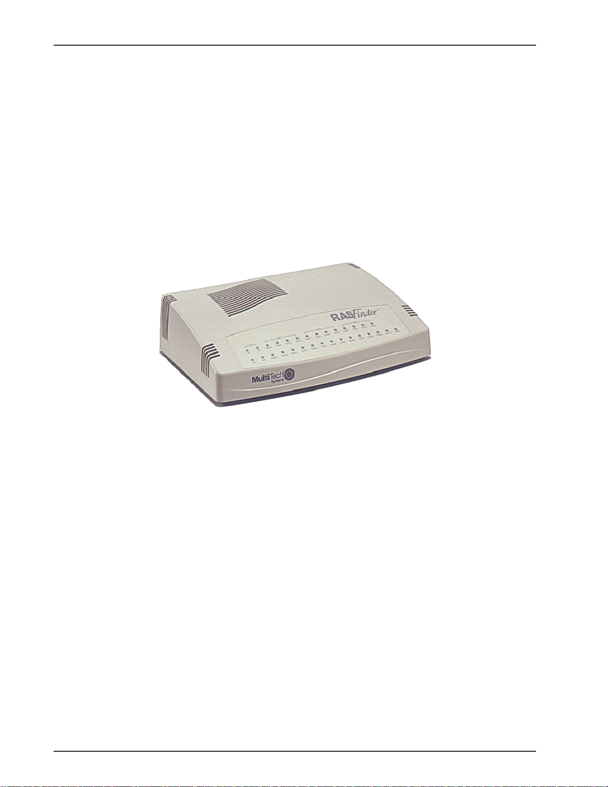
Welcome to Multi-Tech's new RASFinder™, Models RF300E and RF310E, Remote Access Servers
(RAS) for connecting telecommuters and mobile users to a corporate LAN. Both models provide 56K
or ISDN remote server support for dial-out LAN users on IP or IPX networks and LAN security for
dial-in connections with user name and password protection and callback security.
The difference between the two models is the ISDN interface, model RF300E has the European and
rest of the world (ROW) interface (S/T-Interface), model RF310E has the North America interface (U-
Interface).
The RASFinder has three hybrid ISDN ports with six integrated V.90/56K modems for dial-in and dial-
out services, an Ethernet 10BaseT connection for local LAN users, and a command port for
configuration.
System management is provided through the command port using bundled Windows
software which provides easy-to-use configuration menus.
®
based
Preview of this Guide
This guide describes the RASFinder and tells you how to install and configure the unit. The
information contained in each chapter is as follows:
Chapter 1 - Introduction and Description
Chapter 1 describes the new hybrid RASFinder. Descriptions of the front panel indicators and back
panel connectors are provided. A list of relevant specifications is provided at the end of the chapter.
Chapter 2 - Installation
This chapter provides information on unpacking and cabling your RASFinder. The installation
procedure describes each cable connection starting with connecting the power cord, Command port,
LAN and finally the WAN. The software installation process must be done through the Command
port.
Figure 1-1. RASFinder Model RF300E/RF310E
RF300E/RF310E6
Page 7

Chapter 1 - Introduction and Description
Chapter 3 - Software Loading and Configuration
Chapter 3 details the software loading and initial configuration. Initially , the RASFinder software
configures the unit for a Remote Access Server (RAS) configuration. If you want to configure the
RASFinder for a Lan-to-Lan configuration, you will have to change the Remote Port Setup to a Client
or LAN setting. The RASFinder can also be configured to operate in either a RAS application using a
Radius server for security services or a RAS application using the proprietary Remote User Data
Base Utility for remote user authentication.
Chapter 4 - RASFinder Software
Chapter 4 describes the RASFinder software designed for the Windows® environment. The software
contains a number of utilities that allow for downloading updated firmware, creating a proprietary
Remote User Data Base, and a terminal emulation utility for configuring the internal modems. Three
typical applications are provided to show you how the RASFinder can be configured and some insight
into the application.
Chapter 5 - Client Setup
This chapter provides information for enabling and configuring multiple Windows 98/95 or NT® PC
users for Internet access via the RASFinder.
Chapter 6 - RAS Dial-Out Redirector
Chapter 6 describes how Multi-Tech’s Remote Access Server for Microsoft network users enables
them to dial out and fax out through the RASFinder. It provides information on installing and
configuring the WINMCSI modem-sharing software.
Chapter 7 - Remote Configuration and Management
This chapter provides procedures for changing the configuration of a remote RASFinder located
elsewhere on a LAN or at the other end of a modem connection. This chapter also describes typical
Telnet client and Web-browser management of the RASFinder.
Chapter 8 - Service, Warranty and Tech Support
This chapter provides statements concerning the product warranty , provides space for recording
information about your RASFinder prior to calling Multi-Tech’s Technical Support, and includes
instructions for contacting Technical Support and returning your RASFinder to the factory if it requires
service. Also included is information on how to obtain product support through the Internet.
RF300E/RF310E 7
Page 8

RASFinder RF300E/RF310E User Guide
Front Panel
The front panel has four groups of LEDs that provide the status of the LAN connection and link
activity. Two other LEDs indicate the general status of the RASFinder. The Ethernet LEDs display the
activity of the LAN in whether the RASFinder is connected to the LAN, transmitting or receiving
packets, and if a collision is in progress. The Link LEDs display the status of the three links that can
be connected to the RASFinder and show whether a link is ready to transmit or receive serial data.
The last two LEDs indicate whether the self test passed or failed and if the power ON/OFF switch on
the back of the RASFinder is set to ON.
Figure 1-2. Front Panel
LAN
LD TBD.
TX Transmit Data indicator blinks when packets are being transmitted to the local area network.
LK Link indicator lights indicating that the RASFinder is connected to the local area network.
RX Receive Data indicator blinks when packets are being received from the local area network.
BRI x
RD Receive Data indicator blinks when the link is receiving data.
TD Transmit Data indicator blinks when the link is transmitting data.
CD Carrier Detect indicator lights when the link detects a carrier signal.
TR Terminal Ready indicator blinks when the link is ready to transfer data.
BOOT The BOOT indicator lights for 3 minutes when power is applied to the RASFinder; if it
remains on for over 3 minutes, it indicates that a boot failure has occurred.
PWR The power indicator lights when the On/Off switch is in the up (1) position.
RF300E/RF310E8
Page 9

Back Panel
All the cable connections for the RASFinder are made at the back panel. Three groups of cables (all
using RJ-45 jacks) are used with the RASFinder: the Command Port, BRI 1 (2 and 3), and the
Ethernet. The cable connections are shown in Figure 1-3 then defined below .
BRI 1 (2 and 3)
Each of these three RJ-45 jacks is used to connect the RASFinder to a WAN.
Ethernet 10BASET
The Ethernet 10BASET connector is used to connect the RASFinder to a LAN over unshielded
twisted pair (UTP) cable. This connector is an RJ-45 jack.
1
0
10BASET
POWER
Chapter 1 - Introduction and Description
COMMAND
BRI 3 BRI 2 BRI 1
Figure 1-3. Back Panel
COMMAND
The COMMAND connector is used to configure the RASFinder using a PC with a serial port and
running Windows® software. The Command connector is an RJ-45 jack, and a short adapter cable is
provided to convert to a standard serial port DB9 female connector.
Power Connector
The Power connector is used to connect the external power supply to the RASFinder. The Power
connector is a 6-pin circular DIN connector. A separate power cord is connected between the power
supply and a live AC grounded outlet.
RF300E/RF310E 9
Page 10

RASFinder RF300E/RF310E User Guide
Specifications
The RASFinder conforms to the following specifications:
• Routing Protocols - IP and IPX, and bridging for all others
• Ethernet LAN Interface - 10Base-T (twisted pair)
• Three ISDN BRI ports consisting of six V.90/56K modems or six ISDN modems
• Command port - 19.2 Kbps Asynchronous
• 10BaseT Ehternet port
• Two 70-nanosecond 4 MB SIMMs (8 MB, total)
(RAM is expandable to a maximum of 32 MB)
Caution: SIMM speed and size cannot be mixed.
• 1 MB of Flash memory (on two PROMs)
Ethernet Port
• One Ethernet Interface - 10Base-T (twisted pair) RJ-45 connector
Command Port
• Single 56.6K bps asynchronous Command Port using a short RJ-45-to-DB25 cable with a
DB25 female connector
WAN Links
• Six internal V.90/56K modems or six ISDN modems
Electrical/Physical
• Voltage - 115 VAC (Standard), 240 VAC (Optional)
• Frequency - 47 to 63 Hz
• Power Consumption - 10 Watts
• Dimensions - 2.3" high x 8.4" wide x 6.1" deep
• Weight - 1.6 pounds (790g)
Requirement
• PC with Windows 9X/NT/2000, and one available serial COM port to connect to the
Command port of the RASFinder
5.8 cm high x 21.3 cm wide x 15.5 cm deep
* Though this modem is capable of 56K bps download performance, line impairments, public
telephone infrastructure and other external technological factors currently prevent maximum 56
Kbps connections.
RF300E/RF310E10
Page 11

Remote Access Device
Chapter 2 - Installation
Page 12
RASFinder RF300E/RF310E User Guide
Safety Warning Telecom
1. Never install phone wiring during a lightning storm.
2. Never install phone jacks in wet locations unless the jacks are specifically designed for wet
locations.
3. This product is to be used with UL and cUL listed computers.
4. Never touch uninsulated phone wires or terminals unless the phone line has been disconnected
at the network interface.
5. Use caution when installing or modifying phone lines.
6. Avoid using a phone (other than a cordless type) during an electrical storm. There may be a
remote risk of electrical shock from lightning.
7. Do not use the phone to report a gas leak in the vicinity of the leak.
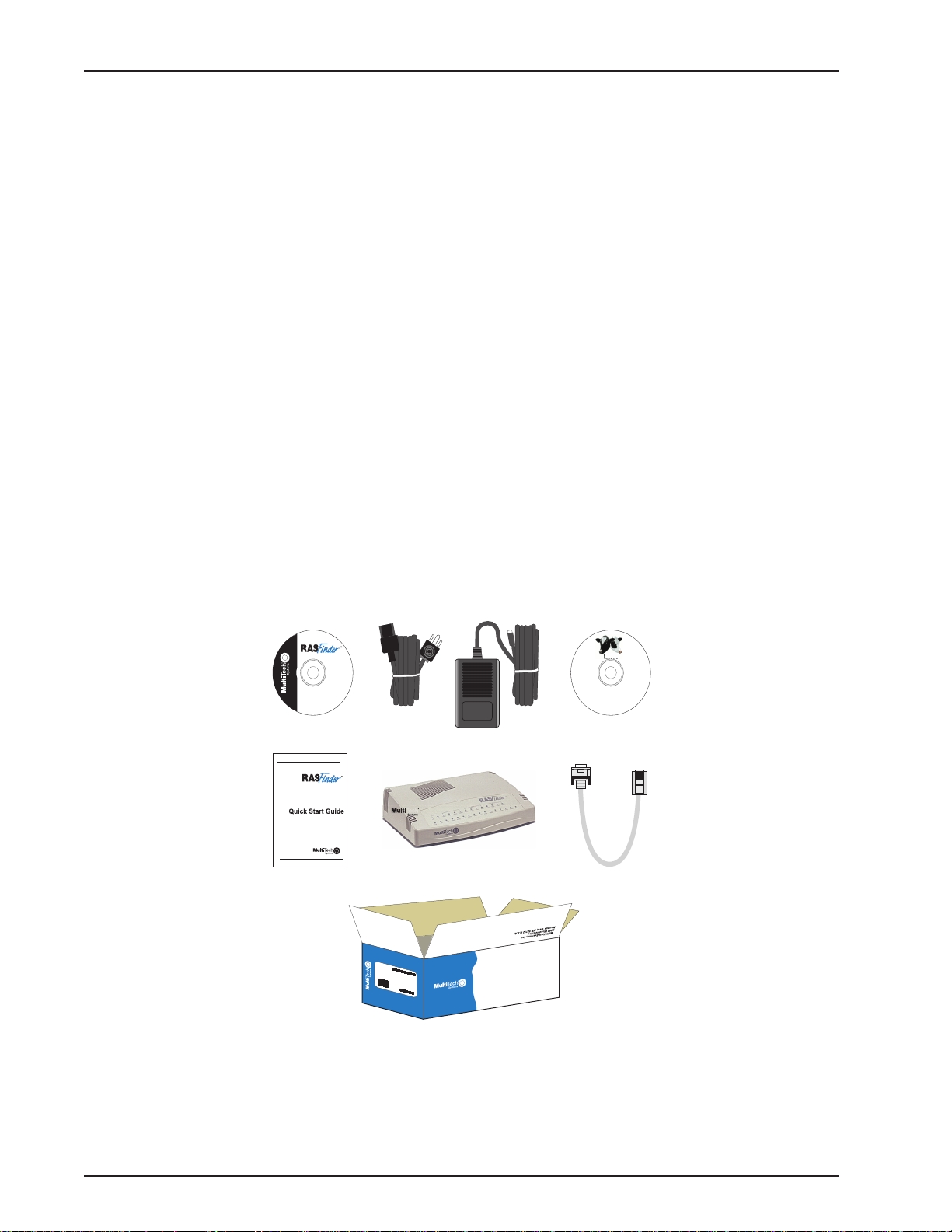
Unpacking
The shipping box contains the RASFinder, external power supply, cables, your Quick Start Guide,
and the RASFinder CD with the RASFinder Software and User Guide in Adobe® Acrobat format.
Inspect the contents for signs of any shipping damage. If damage is observed, do not power up the
unit; contact Multi-Tech’s Technical Support for advice (refer to Chapter 8). If no damage is observed,
place the RASFinder in its final location and perform the procedures in the section on Cabling Your
RASFinder.
Save the shipping box in case reshipment is necessary .
Remote Access Device
www.multitech.com
Remote Access Device
Remote Access Device
RD TD CD NS DS RD TD CD
LK
CL
TD
RD
M
A
D
E
I
N
U
.
S
.
A
V35
.A
.S
U
IN
E
D
A
M
www.multitech.com
Tucows
Figure 2-1. Unpacking
RF300E/RF310E12
Page 13
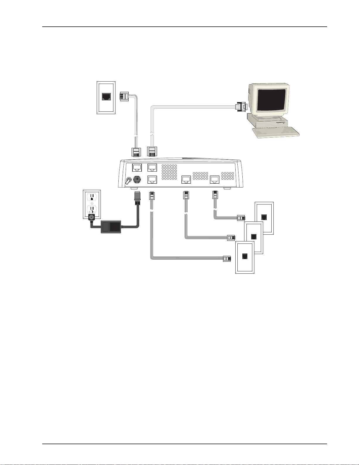
Cabling Your RASFinder
Cabling your RASFinder involves making the proper WAN, Ethernet, Command Port, and Power
connections. Figure 2-2 shows the back panel connectors and the associated cable connections.
The procedures for connecting the cables to your RASFinder are provided below.
Ethernet Connection
10BASET
0
COMMAND
POWER
BRI 3 BRI 2 BRI 1
1
Power Connection
Chapter 2 - Installation
WAN Connections
Figure 2-2. Back Panel Connections
Note: If additional RAM is needed, perform the procedure in the next section, Adding Additional RAM.
The following steps detail the procedures for connecting the cables to your RASFinder.
1 Connect the RASFinder to a PC using the short RJ-45 to DB9 (female) cable provided with the unit.
Plug the RJ-45 end of the Command cable into the Command Port of the RASFinder and the other
end into the PC's serial port. See Figure 2-2.
2 Connect an RJ-45 (UTP) cable to the 10 BASE-T connector on the back of the RASFinder . Connect
the other end of the cable to your LAN.
3 Connect one end of a UTP cable to each of the BRI Connectors on the RASFinder (labeled BRI 1,
BRI 2, and BRI 3) and connect the other end to a WAN jack (as shown in Figure 2-2).
4 Connect one end of the power supply to a live AC outlet, then connect the other end to the
RASFinder as shown in Figure 2-2. The power connector is a 6-pin circular DIN connector .
5 Turn on power to the RASFinder by setting the ON/OFF switch on the back panel to the ON position.
At this time your RASFinder is completely cabled.
Proceed to the next section to install the RASFinder software.
RF300E/RF310E 13
Page 14

RASFinder RF300E/RF310E User Guide
RF300E/RF310E14
Page 15

Remote Access Device
Chapter 3 - Software Loading and Configuration
Page 16

RASFinder RF300E/RF310E User Guide
Introduction
This chapter covers procedures for loading the RASFinder software from a Windows PC (Win98/95
or WinNT) and configuring your RASFinder. Configuration includes setting up the LAN and W AN port
IP addresses, setting up the ISDN configuration default parameters, then downloading the default
setup to the target ISDN RASFinder.
Before You Start Loading your Software
Consider the following choices before you configure your RASFinder and record your selections on
the following pages; then refer to them while loading your software.
Network Configuration
ü Network Switch Type_________________________________________
Select the network switch type your ISDN service provider uses at its local central office. You can set
the RASFinder to NET3 (EuroISDN), or 1TR6 (German), AT&T 5ESS, DMS-100, or NI-1. If you do
not know the switch type, you can get the information from your ISDN service provider.
ü Data TEI_____________________________________________________
The Data TEI (Terminal Endpoint Identifier) is assigned to the data channel. Y ou can select “Auto TEI,”
a fixed TEI, number (from 0 to 63), or “Disabled.” A TEI is a number used by the central office switch to
uniquel y identify each device that is connected to the network. When it uses dynamic TEI assignments
(Auto TEI), the central office switch assigns a TEI each time the RASFinder connects to the network.
However, the ISDN service provider may assign a fixed TEI at subscription time, in which case you
must configure the RASFinder with the fixed TEI number. You can also disable the channel, which may
be useful when multiple RASFinders are attached to a network terminator bus.
ü Voice TEI___________________________________________________
The Voice TEI is the TEI assigned to the voice channel. You have the same choices as for the Voice
TEI: “Auto TEI,” a fixed TEI number (from 0 to 63), or “Disabled.”
ü Data SPID__________________________________________________
The RASFinder must be configured with the Service Profile Identifier (SPID). The data SPID is
assigned by the local phone company and is for the specific Basic Rate Interface (BRI) line to which
the RASFinder will be attached. The data SPID string can have up to 20 characters. The data SPID
is not used if the switch type is set to NET3.
Note: For DMS-100 switches, any ASCII character except the underline (_) character is valid. For
NI-1 and AT&T switches, only the digits 0-9 are valid.
ü Voice SPID__________________________________________________
The voice SPID is assigned by the local phone company and is for the specific BRI line to which the
RASFinder will be attached. The voice SPID string can have up to 20 characters. The data SPID is
not used if the switch type is set to NET3.
Note: For DMS-100 switches, any ASCII character except the underline (_) character is valid. For
NI-1 and AT&T switches, only the digits 0-9 are valid.
ü Data Directory Number________________________________________
The data Directory Number (DN) is a telephone number that is assigned to the RASFinder at
subscription time by the ISDN service provider. The DN is a string of up to 24 characters; valid
characters are 0-9, the * character, and the # character.
ü Voice Directory Number_______________________________________
The voice Directory Number (DN) is a telephone number that is assigned to the RASFinder at
subscription time by the ISDN service provider. The DN is a string of up to 24 characters; valid
characters are 0-9, the * character, and the # character.
RF300E/RF310E16
Page 17

Chapter 3 - Software Loading and Configuration
Call Control Parameters
ü Persistent DTR Dialing_______________________________________
A high DTR (Data Terminal Ready) signal on the Command port indicates that your computer or
terminal is ready to communicate with your RASFinder. DTR normally goes high when a
communication program starts or is ready to dial. Persistent DTR dialing enables the RASFinder to
automatically redial the number stored in memory location 0 whenever DTR is high and the serial port
does not have an active call. You may enable or disable this feature.
ü Calling Line Identification_____________________________________
Identifies whether the two endpoints of a connection are enabled or disabled. Since RING
messages only appear for ISDN data calls, the CLI feature does not define a means of conveying
Calling Party information to the terminal for ISDN voice calls. The CLI information is only included
with the first RING message for a given incoming call and appears as follows:
RING
FM: 5552000 TO: 5551000
If the Calling Party Number information is not included in the incoming SETUP message, the RING
message appears as follows:
RING
TO: 5551000
If the Called Party Number information is not included in the incoming SETUP message, the RING
message will appear as follows:
RING
FM: 5552000
If neither the Called Party Number, nor the Calling Party Number is included in the incoming SETUP
message, the RING message will contain no additional information.
ü Auto Protocol Detection -
Identifies that automatic protocol detection is enabled or disabled for an ISDN data call. The default
setting is 1, which enables the Auto-Protocol Detection function.
ü Auto Answer Data Calls ____ __________ Rings to Answer__________
Select Auto Answer if you want your RASFinder to automatically answer all incoming data calls (this
option does not affect the analog port). The Rings to Answer number, in the range of 1 to 255,
selects the number of rings the RASFinder waits before answering an incoming call. The default is
one ring.
Data Control
ü Data Protocol _______________________________________________
The data protocol, also known as the B-channel protocol and the rate adaption protocol, is the
“language” that is spoken over each 64 Kbps channel between two ISDN devices. The devices on
both ends of the ISDN link must use identical data protocols.
ü Dialing Method _______________________________________________
Select either the “Enbloc” or the “Overlap” dialing method for use when establishing a data call. Your
ISDN service provider determines the dialing method. The en bloc method is used for most ISDN
dialing; however, you can select the overlap method if you are working with a private network.
RF300E/RF310E 17
Page 18
RASFinder RF300E/RF310E User Guide
Installing Your RASFinder Software
The default application of the RASFinder is as a Remote Access Server equipped with a database of
remote users for dialing into their corporate LAN. The RASFinder can also be configured to serve as
a LAN-to-LAN router; however, this requires additional setup through the main menu after completion
of the basic software installation process.
Note: If you are configuring your RASFinder and loading software for North America (US
Parameters), be sure you have Model RF310E (U-Interface).
If you are configuring your RASFinder and loading software for European Parameters or Rest of
World (ROW), be sure you have Model RF300E (S/T -Interface).
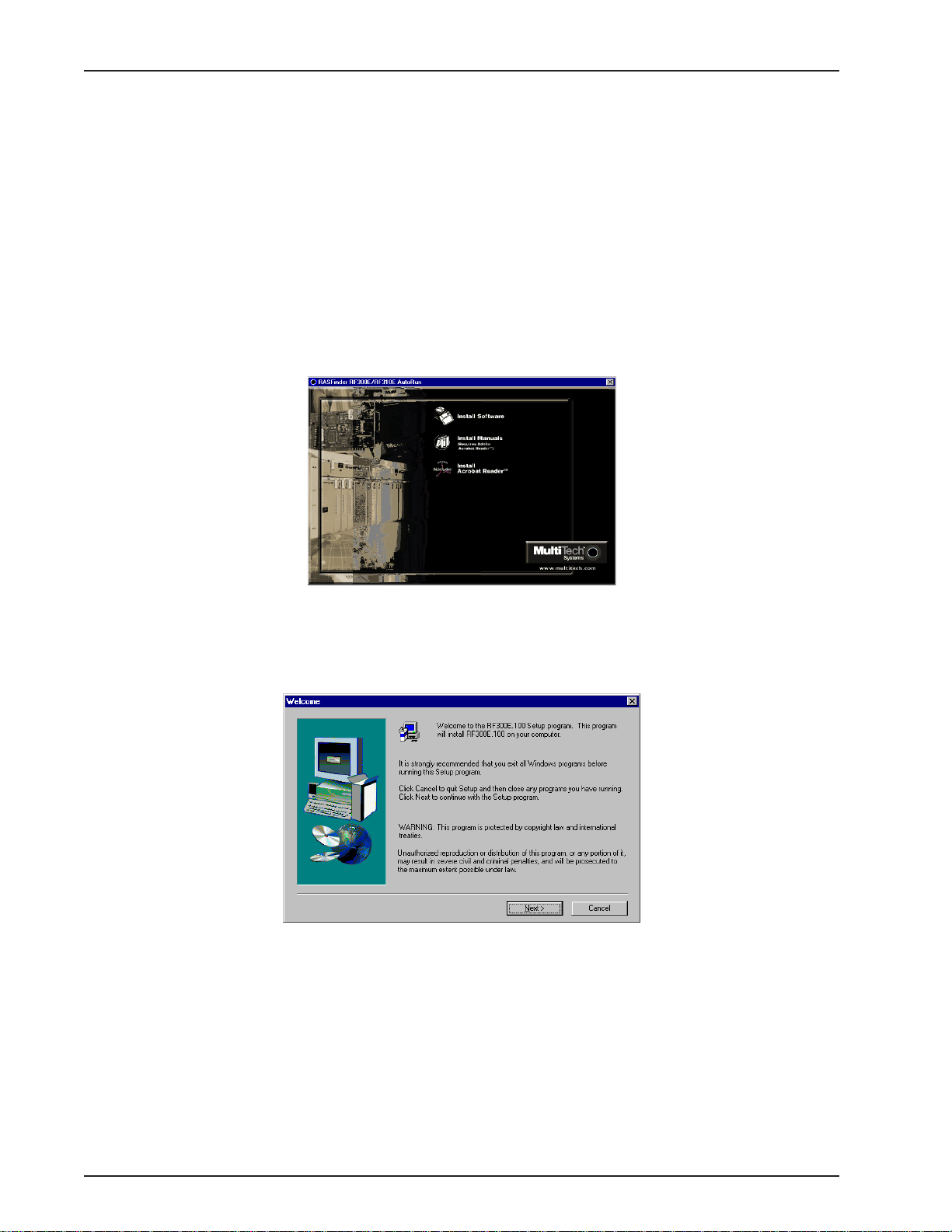
1. Insert the RASFinder CD-ROM into the CD-ROM drive on your local PC. The CD-ROM should start
automatically; however, it may take 10 to 20 seconds for the Multi-Tech RASFinder Autorun screen to
appear.
2. If the Multi-Tech Installation CD Screen does not appear automatically, click My Computer, then
right-click the CD-ROM drive icon and click Autorun.
3. When the Multi-Tech Installation CD Screen appears, click the Install Software icon.
4. The Welcome screen is displayed.
Press Enter or click Next> to continue.
RF300E/RF310E18
Page 19

Chapter 3 - Software Loading and Configuration
5 The Choose Destination Location dialog box is displayed. Follow the onscreen instructions to
install your RASFinder software.
You can either choose a different Destination Location for your RASFinder software by clicking
Browse, or select the default destination by clicking Next> or pressing Enter. It is recommended that
you accept to the default location, c:\RF300E.100.
6 When the Select Program Folder dialog box enables you to name the program group for the
RASFinder icons. You can either select the default name, RF300E 1.00 or name it anything you like.
Press Enter or click Next> to continue.
7 The next dialog box enables you to designate the COM port of the PC that is connected to the
RASFinder. On the Select Port field, click the down arrow and choose the COM port of your PC
(COM1 -- COM4) that is connected to the RASFinder.
Click OK to continue.
RF300E/RF310E 19
Page 20
RASFinder RF300E/RF310E User Guide
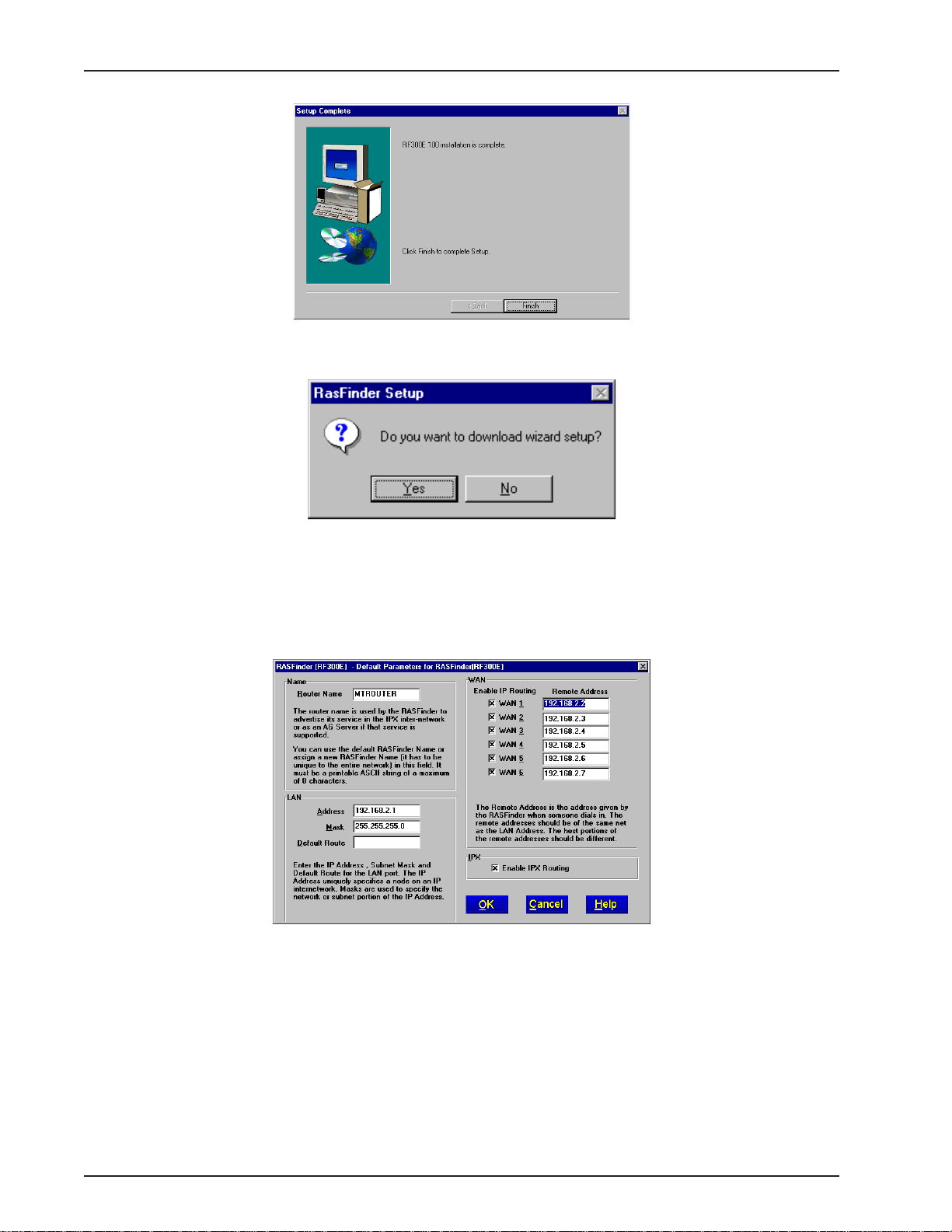
8 The software is loaded onto your pc, then the Setup Complete dialog box is displayed.
Click Finish to continue.
9 The following message appears:
10 Click Yes to download wizard setup. Clicking No prevents you from setting up the defaults and
downloading them to the RASFinder; instead, you are returned to the program group.
11 The Default Parameters dialog box appears. This dialog box enables you to assign the router name
(required for IPX routing), establish the IP address, mask, and default route for the LAN port, enable
or disable IPX routing, set up the remote addresses for the WAN ports, and disable any W AN ports
not used.
Router Name: If this is the only RASFinder on your network, you can use the default Router Name
(MTROUTER); otherwise, you must assign a new Router Name in this field. The Router Name can
be any printable ASCII string of up to 8 characters. The RASFinder will use this name to advertise its
service in the IPX internetwork.
The default LAN IP Address has to be changed to your unique LAN port address. In the LAN group,
change the default Address to the value assigned to your LAN port. When you change the LAN
Address, the remote WAN addresses also change to the same network and in sequential order .
Change the default Mask to the value assigned to your LAN port.
If you established a Default Route on your LAN, enter the address of the route.
RF300E/RF310E20
Page 21
Chapter 3 - Software Loading and Configuration
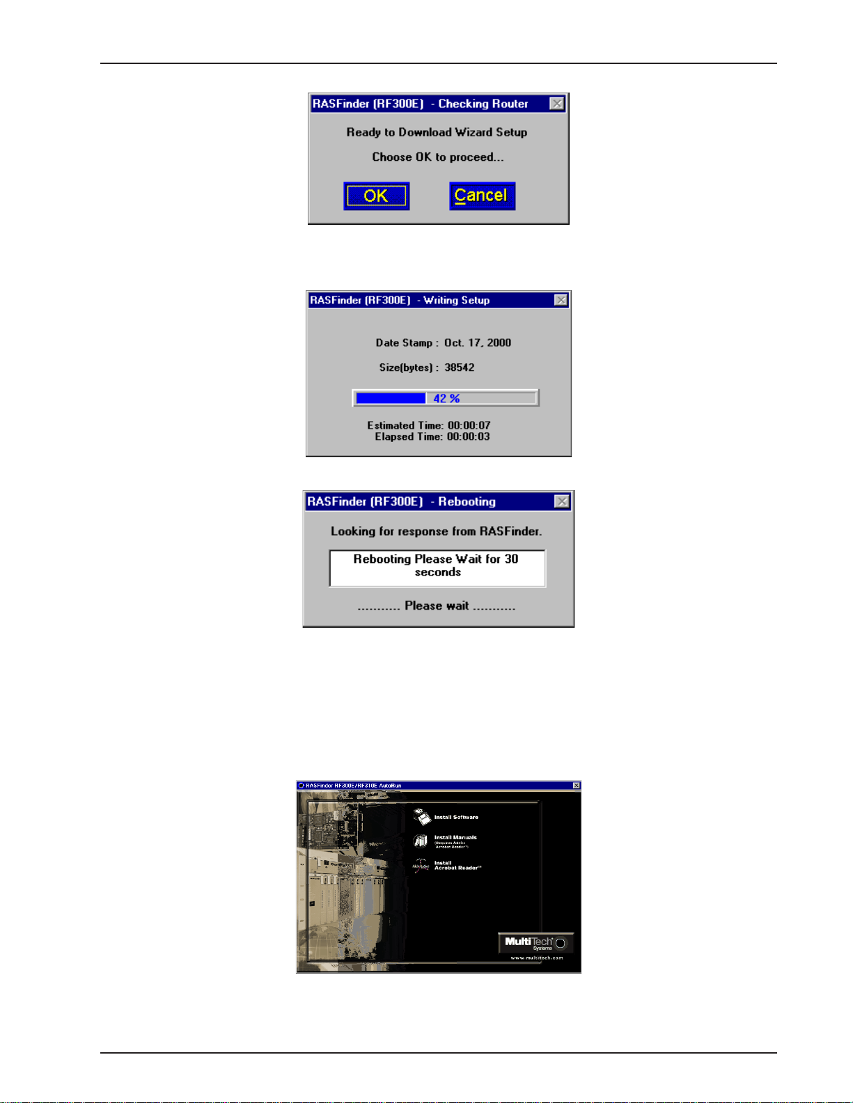
12 The following message is displayed.
Click OK to proceed.
13 The Writing Setup dialog box (with the current date and the file size in bytes) is displayed as the
setup configuration is written to the RASFinder.
14 Next, the Rebooting dialog box is displayed.
15 Check to ensure that the BOOT LED on the RASFinder goes Off after the download is complete and
the RASFinder is rebooted (the Rebooting dialog box goes away). This may take several minutes as
the RASFinder reboots.
16 You are returned to the Multi-Tech RASFinder Autorun screen where you can now install (on your
PC’s hard drive) either Acrobat Reader (by clicking the Acrobat Reader icon) or the User Guide.
To install the User Guide, click the Install Manuals icon, then click OK and the files will install at
C:\Program Files\Multi-T ech Systems, Inc.\RF300E\Documentation unless you browse and select
an alternate directory for installation.
RF300E/RF310E 21
Page 22
RASFinder RF300E/RF310E User Guide
17 If you need to enter ISDN parameters, proceed to step 18.
If you want at this time to set up your RASFinder as a RAS with the Proprietary user database,
proceed to Setting Up Your Remote User Database section in this Quick Start Guide.
If you want at this time to set your RASFinder so that a Radius server provides your user database,
proceed to Setting Up RADIUS.
If you want at this time to set up your RASFinder for LAN-to-LAN routing, proceed to the Final
Routing Setup section.
18 If you need to enter specific ISDN parameters (SPIDs) and DNs for North America, or data and voice
ISDNs and subaddresses for European Parameters, click Start | Programs | RF300E 1.00 |
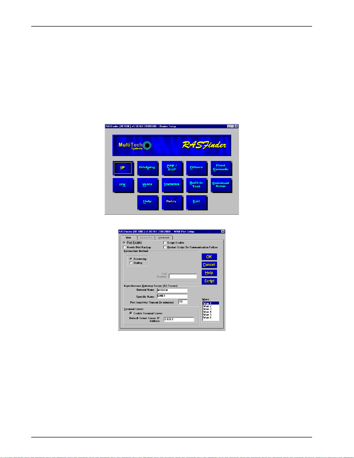
RASFinder Configuration, or double-click the RASFinder Configuration icon in the RF300E 1.00
icon group window when it is displayed on your desktop. The main menu (Router Setup) is
displayed.
19 From the Main menu, click the WAN button. The WAN Port Setup screen is displayed.
RF300E/RF310E22
Page 23
Chapter 3 - Software Loading and Configuration
20 Click the Advanced tab.
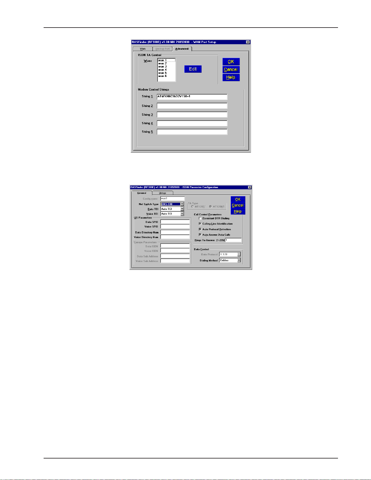
21 Select (highlight) the WAN port you want to configure, then click Edit. The ISDN Parameter
Configuration dialog box is displayed with the Config name window displaying the WAN port you just
selected.
22 Click the down arrow for Net Switch Type and highlight the switch type used by your Telco. If
necessary , refer to your Network Switch Type entry in Before You Start Loading your Software. The
default is NET3 (for EuroISDN). A vailable selections for the USA are: AT&T 5ESS, DMS-100, and NI-
1. VN4 is for France, ITR6 is for Germany, and INS64 is for ISDN BRI (Japanese).
23 Click the Data TEI field on the General tab. Refer to your Data TEI entry in the Network
Configuration section in Before You Start Loading Y our Software. If the Data TEI is dif ferent, click the
drop-down list arrow and click the selection that corresponds to the Data TEI (i.e., Disabled, Auto
TEI, or zero to 63) supplied by your Internet service.
24 Click the Voice TEI field on the General tab. Refer to your V oice TEI entry in the Network
Configuration section in Before You Start Loading Y our Software. If the Voice TEI is different, click
the drop-down list arrow and click the selection that corresponds to the Voice TEI (i.e., Disabled, Auto
TEI, or zero to 63) supplied by your Internet service.
25 Depending on the switch type chosen above, either the US Parameters group or the Europe
Parameters group will be activated.
If the US Parameters group is activated you may have to enter the SPID and Directory number(s)
associated with the WAN port in the Config name window .
A SPID (Service Profile IDentifier) is a number that is supplied to you by your local phone company
which encompasses the phone number.
A Data or Voice Directory Number (DN) is the phone number assigned to that B-Channel for the BRI
line provisioned by your phone company . If a DN is assigned, then only the device associated with
that WAN port will respond to the call.
RF300E/RF310E 23
Page 24

RASFinder RF300E/RF310E User Guide
CAUTION: WANs 1 and 2 correspond to BRI 1. B-Channel 1 of BRI 1 corresponds to WAN 1, and B-
Channel 2 of BRI 1 corresponds to WAN 2. The BRI line from the Telco has to be connected to the
corresponding port on the RASFinder (e.g., BRI Line 1 has to be connected to BRI 1 port on the back
of the RASFinder. The SPID and Directory Number (if used) for the BRI line assigned by the Telco
have to be entered on the ISDN Parameter Configuration dialog box for the corresponding WAN
number. WANs 1 and 2 are associated with BRI Line 1 and BRI 1 port on the back of the RASFinder.
Each of these entries has to correspond to the way the Telco provisioned the line, or else calls will not
go through.
If the chosen switch type activates the Europe Parameters group, you may have to enter Data/Voice
ISDN and Sub Addresses associated with the WAN port displayed in the Config name window.
Enter the Data/Voice ISDN associated with the WAN port displayed in the Config name window.
The Data and Voice ISDN numbers can be up to 20 characters in length. The Data/Voice ISDNs are
assigned by your local phone company for the specific BRI line attached to the RASFinder. The BRI
line has to correspond to the BRI port on the back of the RASFinder and the B channel of that line
has to correspond to the WAN Port number; e.g., BRI Line 1 B-Channel 1 corresponds to W AN 1 and
BRI Line 1 B-Channel 2 corresponds to WAN 2.
26 When you have finished entering the Parameter information for your WAN port, click OK and you are
returned to the WAN Port Setup dialog box; the ISDN TA Control group and the W AN number you
just configured will be highlighted.
27 Highlight the next WAN port you want to configure, then click Edit. Repeat steps 22 and 26 for each
WAN port you need to configure.
28 When all the necessary WAN ports are configured, click OK
29 At this time your RASFinder is operational.
If you want to assemble your Remote User Database, proceed to the next section.
If you want to setup your Radius, proceed to Setting Up RADIUS section.
If you are setting up your RASFinder for routing, proceed to the Final Routing Setup section.
twice to return to the Main menu.
RF300E/RF310E24
Page 25
Chapter 3 - Software Loading and Configuration
Setting Up Your Remote User Database
The proprietary Remote User Data Base supports remote dial-in users for user name, password, and
port availability. Each dial-in user needs an entry in this database. You can add remote users, remove
users, or edit information in the database.
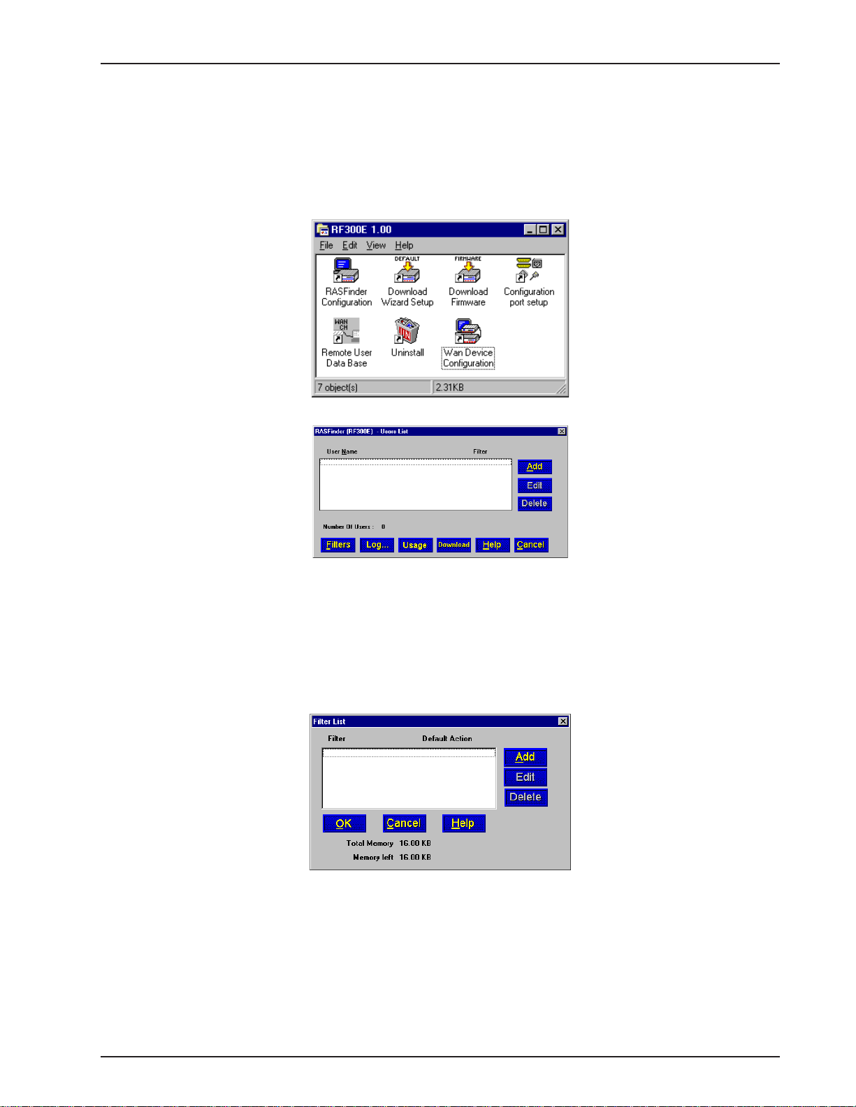
1 From your desktop, click Start | Programs | RF300E 1.00 | Remote User Data Base, or double-click
the Remote User Data Base icon in the RF300E 1.00 icon group window (below).
2 An Accounting Info - Read screen appears briefly, then the Users List dialog box is displayed.
Filters
Part of the database is the type of filtering that is applied to each user (e.g., filtering on an IP address
or filtering on a specific protocol). These filtering conditions are established by clicking the Filters
button.
3 Click Filters to establish the filtering parameters for the remote user entry. the Filters List dialog box
is displayed.
Click the Add button.
RF300E/RF310E 25
Page 26
RASFinder RF300E/RF310E User Guide
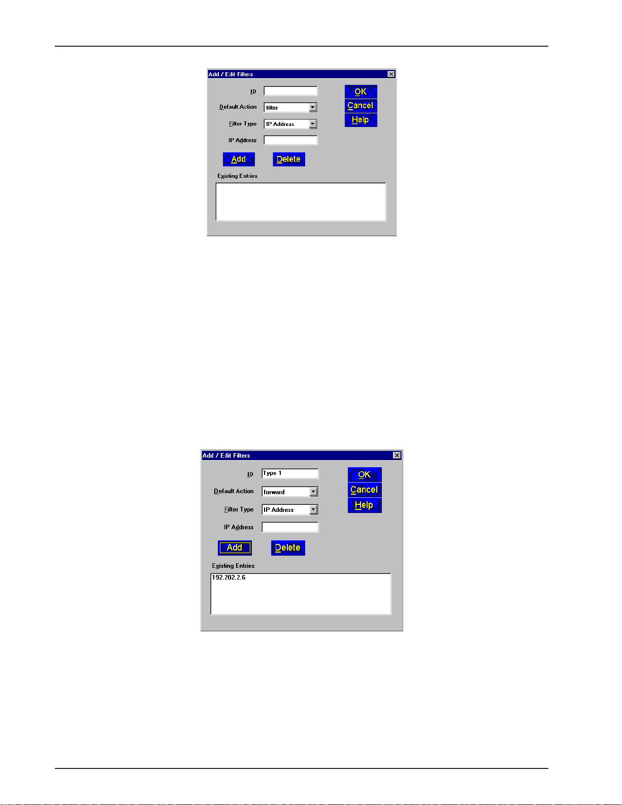
4 The Add/Edit Filters dialog box is displayed.
5 Build your filtering parameters by filling in the following fields for each remote user.
ID
This field requires a unique filtering identification characterizing the type of filtering used. The ID can
be up to 9 alphanumeric characters in length; examples are: Type 1, Server 1, Setup 1, etc.
Default Action
This drop-down list enables you to select either filter or forward. If you select filter, then the entry will
be transmitted with filtering properties. If you select forward, you will still have to select a filter type,
etc.; however, the entry will be transmitted without filtering properties. The default setting is filter.
Filter Type
The Filter T ype drop-down list enables you to select the filter type. The filter types are either IP
Address, Protocol, or Domain Name. The default setting for Filter Type is IP Address.
• IP Address – If the filter type is IP Address, enter the IP Address of the remote user in
dotted-decimal format, then click the Add button to move it to the Existing Entries text box
at the bottom of this dialog box.
• Protocol – If you select Protocol as the filter type, the IP Address text box changes to
Protocol and Port drop-down list fields. Select either TCP or UDP from the Protocol dropdown list and select either Telnet, FTP, or SFTP from the Port drop-down list, then click the
Add button to move these selections to the Existing Entries text box at the bottom of this
dialog box.
• Domain Name – If you select Domain Name as the filter type, the IP Address text box
changes to a Domain Name field. Enter the domain name consisting of a sequence of
names separated by periods (dots) followed by an extension; e.g., “pictures.computers.com.”
Click the Add button to move the domain name to the Existing Entries text box at the
RF300E/RF310E26
Page 27

Chapter 3 - Software Loading and Configuration
bottom of this dialog box. The domain name can be up to 39 alphanumeric characters
including periods.
Click OK to add the current entry to the Filters List dialog box, then repeat step 5 until all necessary
Filter IDs are defined.
6 When done, click OK again to return to the Users List dialog box, then click Download to save the
filter entries to the RASFinder.
While still at the Users List dialog box, click Add.
Build User Database
7 The Add Users dialog box is displayed.
8 Build your user database by filling in the following fields for each user.
User Name
The User Name can have as many as 39 characters. All printable characters are permitted with the
restriction that no blanks are allowed in the user name. In dial-in and dial-out applications, the user
name is treated as a case insensitive string.
User Password
The User Password can have as many as 7 characters. In places where the password is used as a
character string, it is treated as a case insensitive string. Elsewhere (PPPs CHAP), it is treated as a
RF300E/RF310E 27
Page 28
RASFinder RF300E/RF310E User Guide
case sensitive pattern.
Filter
The drop-down list enables you to select a unique filter entry that was already defined in the ID field in
the Add/Edit Filters dialog box.
Call Back
Click this check box to enable the Call Back function. If the user is at a number where he wants to be
called, he can choose the specific number for call back. For this to work, the Call Back option must
be enabled (activated) and the Call Back Security Enabled option must NOT be enabled (activated).
The remote user would then use a standard PPP client or ASCII terminal to dial-in.
To enable Call Back
three boxes/fields.
• Call Back Security Enabled
This parameter is of use in dial-in applications where the user is always called back at a specific
number. Enabling this parameter (Alt-S) lets the administrator assign the call back parameters. Leave
this function disabled if the user is permitted to choose the call back number and the call back delay.
• Call Back Number
The Call Back Number is editable only if Call Back Security is enabled (checked). This is the number
where the user will be called back. In this case, the user cannot choose the number where he wants
to be called back.
Note: You can enter the Call Back Number with or without dashes, the modem will ignore them if they
are present.
• Call Back Delay
Call Back Delay is editable only if Call Back Security is enabled. This specifies the duration (in
seconds) after which the user will be called back at the administrator-assigned number.
Dial In Ports
The systems administrator can enable (highlight) any WAN Ports 1 through 6 to be made available for
dialing in to the RASFinder.
Dial Out Ports
The systems administrator can enable (highlight) WAN Ports 1 through 6 to be made available for
dialing out from the RASFinder.
Click the Rights button to assign user permissions for the remote user.
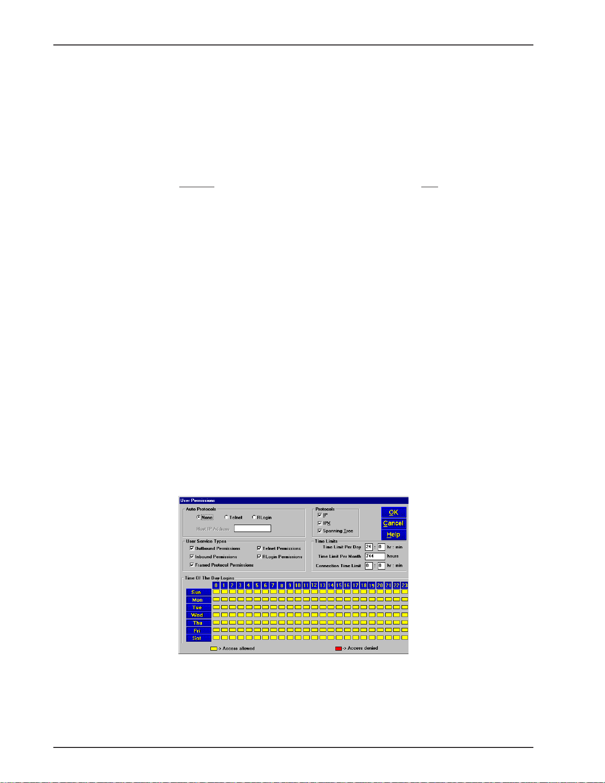
9 The User Permissions dialog box is displayed.
Security , you must enable (check) the Call Back option and fill in the following
10 Build your user permissions database by filling in the following fields for each remote user.
Auto Protocols
This group enables the systems administrator to assign either unrestricted LAN/Intranet access or
limited protocol access. The three available options are:
RF300E/RF310E28
Page 29

Chapter 3 - Software Loading and Configuration
• None
This option (the default setting) gives the user unrestricted access to the LAN/Intranet.
• Telnet
This option allows Telnet sessions between the designated server (defined in the Host IP Address
field) and the remote user. Telnet is an applications-level protocol commonly found in IP-based
networks that allows terminal emulation at a remote workstation. If you select Telnet, you must enter
an IP address in the Host IP Address field. This limits the user to only specific functions on the
network.
• RLogin
This option allows the RASFinder to be used as an RLogin client for connecting to an RLogin Server
(defined in the Host IP Address field). RLogin is an application protocol that provides a terminal
interface between Unix hosts using TCP/IP network protocol. Unlike Telnet, RLogin assumes that the
remote host is a Unix machine. If you select RLogin, you must also enter an IP address in the Host
IP Address field. This limits the user to only specific functions on the network.
Host IP Address
Enter the IP Address for the Telnet or RLogin host computer (server). The Host IP Address must be in
dotted-decimal notation format.
Note: This field is enabled (activated) only when either Telnet or RLogin is enabled.
Protocols
The Protocols group enables you to limit the remote user to IP routing, IPX routing, or bridging
(Spanning Tree); or, a combination of any two or all three routing protocols. The default setting is for
all three protocols enabled.
User Service T ypes
The User Service Types group enables you to set the permissions for the entry being configured. The
systems administrator can enable or disable the following options to customize the types of services
for a particular remote user. By default, all permissions are enabled. To deny permissions to the entry
being configured, click (check) the box to the left of the permission to disable the feature.
• Outbound Permissions - grants dial-out rights to remote user.
• Inbound Permissions - grants dial-in rights to user.
• Framed Protocol Permissions - grants the remote user framed protocol rights (e.g.,
Framed Protocol – PPP). By enabling (checking) this option, the user becomes an
unrestricted user (i.e., both framed and unframed protocols are allowed).
• T elnet Permissions - grants the remote user Telnet file transfer rights.
• RLogin Permissions - grants the remote user RLogin server connection rights.
Time Limits
The Time Limits group enables the systems administrator to impose various types of time-related
restrictions on the user account.
Time of the Day Logins
The User Permission grid enables the administrator to deny a remote user Internet access at certain
times during the week. This would be applicable when the administrator wants to bring a system
down for a particular reason and doesn’t want users to access the Internet at that time.
By default, all time periods are color-filled with yellow indicating that the remote user has permission
to access the Internet all the time. To deny permission for certain periods of time, click all applicable
yellow boxes over the target time range to toggle them to red (Access Denied).
11 Click Add User to continue adding users to your database.
12 After each user is defined in the Add Users dialog box and all the user permissions (Rights) are
configured, click OK to display the updated Users List dialog box.
13 Click Download to write the database to the RASFinder.
RF300E/RF310E 29
Page 30
RASFinder RF300E/RF310E User Guide
Setting Up Remote Access Dial In User Server (RADIUS)
RADIUS is an optional security feature that uses a single authentication server to centralize security
on networks with large modem pools, especially those with multiple communication servers.
1. From your desktop, click Start | Programs | RASFinder 3.10 | RASFinder Configuration, or
double-click the RASFinder Configuration icon in the RASFinder 3.10 icon group window when it
is displayed on your desktop.
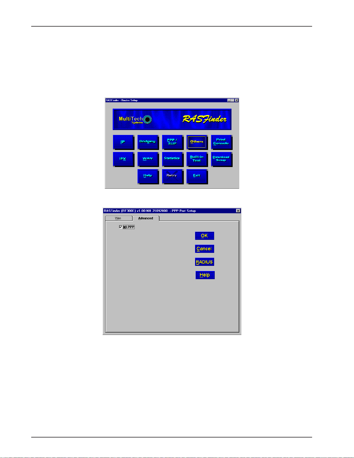
2. The main menu (Router Setup) is displayed.
Click PPP / SLIP to continue.
3. The PPP Port Setup dialog box is displayed; click the Advanced tab.
Click RADIUS to continue.
RF300E/RF310E30
Page 31

4. The Radius Setup dialog box is displayed.
Chapter 3 - Software Loading and Configuration
5. Click RADIUS Enable to enable Radius security services for all ports on this RASFinder.
6. Click Accounting Enable if you want Radius to track accounting information such as login and
logout times, bytes sent and received, etc.
7. Leave Allow Call if Security Server Down unchecked (disabled) to prevent users from logging in if
the security servers are down.
8. Click Assign Remote Address Using RADIUS to enable the Radius Server to automatically assign
the IP Address of the WAN port on the RASFinder that the user will dial into.
9. Obtain the Shared Secret from the Radius network administrator. The Shared Secret must be the
same secret that is used on the Radius server whose address is being supplied for the Radius
primary server address entry .
10. Obtain the Radius server address from the Radius network administrator that will provide the security
to the RASFinder. The Radius server address is to be enterred in the RADIUS Primary Server
Address field.
1 1. If additional servers are being used as backup servers, obtain their address(es) from the Radius
network administrator and enter them in Backup Servers group. The first backup server address is
enterred in the Backup Server Address 1 field. Any additional backup server addresses are to be
enterred in the Backup Server Address 2 and Backup Server Address 3 fields.
12. A set of default attribute values will be displayed in the Attribute V alues group. These default values
are used with the Multi-Tech Radius Server. You do not have to change these values if your
RASFinder is communicating with Multi-Tech’s Radius Server. If you are using another vendor’s
Radius Server to communicate with your RASFinder, you will have to communicate with your Radius
Server network administrator to see how he/she has set up these attribute values and then change
the default values to the values being used by that Radius server.
13. Click OK when you are finished.
RF300E/RF310E 31
Page 32

RASFinder RF300E/RF310E User Guide
Final Routing Setup
1. From your desktop, click Start | Programs | RASFinder 3.10 | RASFinder Configuration, or
double-click the RASFinder Configuration icon in the RASFinder 3.10 icon group window when it is
displayed on your desktop.
2. The main menu (Router Setup) is displayed.
Click PPP/SLIP button to continue.
3. The PPP Port Setup dialog box is displayed.
On the WAN tab, click Client or LAN in the Remote Port Setup group in the bottom right corner;
this enables Client or LAN and disables the default, Client only. Select another WAN port you are
using and repeat until ALL the WAN ports are switched to Client or LAN.
RF300E/RF310E32
Page 33

Chapter 3 - Software Loading and Configuration
4. If you are going to combine the two WAN ports together, i.e., a single IP address, you need to enable
the MLPPP option from the Advanced tab.
Note: When the dialog box “When a PPP port is Client-or-LAN type:” appears, click on the OK button
each time the dialog box appears. You are returned to the Main menu.
5. From the Main menu, click on the IP button and the IP Port Setup dialog box appears with the
Ethernet tab active and the Port Address displaying your LAN IP Address.
Click on the WAN tab
RF300E/RF310E 33
Page 34

RASFinder RF300E/RF310E User Guide
6. On the WAN 1 tab, change the Port Address and Remote Address groups to be on separate
networks from the Ethernet LAN port.
If you enabled MLPPP option on the PPP Port Setup dialog box, the IP addresses for all three WAN
ports have to be identical and the remote WAN port addresses have to be within the same network
and identical.
If you did not enable MLPPP option, the WAN port addresses have to be on a dif ferent network from
the LAN port address and have to be different from each other .
7. Click on each of the WAN tabs and change the Port Address group and Remote Address group to
conform with the settings for WAN 1.
8. Click OK to return to the Main menu.
9. From the Main menu, click Download Setup button to write your new configuration to the
RASFinder. After your configuration is written to the RASFinder, you are returned to the Main menu.
Your RASFinder is now configured for LAN-to-LAN routing.
RF300E/RF310E34
Page 35

Remote Access Device
Chapter 4 - RASFinder Software
Page 36

RASFinder RF300E/RF310E User Guide
Introduction
This chapter describes the RASFinder software and explains how to make changes to the
configuration of your RASFinder. The major configuration parameters were established during the
loading of the software (Chapter 3). The RASFinder software and configuration utilities allow you to
make changes to that initial configuration.
The RASFinder software allows you to refine your configuration based on your network connections.
The software is based on a main menu (RASFinder Setup) that allows you to consider all the
parameters for a particular feature (e.g., IP or IPX protocol, Bridging, or setting up a WAN port for
PPP or SLIP protocol). These features, along with others are discussed in detail in the RASFinder
Configuration section later in this chapter.
The other five configuration utilities offer additional functionality. The Download Wizard Setup
guides you through the initial configuration and software downloading, as described in Chapter 3.
Download Firmware allows you to download new versions of firmware when enhancements become
available. The Configuration Port Setup utility allows you to change the method by which you
access the RASFinder (i.e., direct connection of a PC to the Command Port on the RASFinder, or via
your LAN port on the RASFinder). The Uninstall RASFinder Configuration utility is designed to
remove the software from your PC. The W AN Device Configuration utility opens the Print Console,
a terminal emulation program that enables you to confiure the built-in modems. The Remote User
Data Base utility (supported through the command port) allows you to establish and maintain a
database of information about your remote users. You can add and remove remote users, or edit
existing user information in the database.
Your RASFinder software includes the RASFinder on-line Help system. The Help is designed to be
context sensitive. Clicking the Help button within a given dialog will provide definitions and
recommended values for each button, option, and field for that dialog. In some instances, you will
also be presented with a list of related topics that can be displayed by clicking the green, underlined
text. In addition, you can search the entire Help system (via the Index tab) for definitions and
references to specific terms, fields, and recommended values where applicable.
Before You Begin
The RASFinder software operates in a Microsoft Windows® environment. Your RASFinder RF300E
1.00 program group, with all the utilities described above, is accessible by clicking Start I Programs I
RF300E 1.00 I (utility), or by double-clicking the utility icon in the program group in My Computer
(C:\Windows\Start Menu\Programs\RF300E 1.00). The program group is shown here:
RF300E/RF310E36
Page 37

Router Configuration
All changes to your RASFinder configuration are initiated through the Router Setup menu. The
Router Setup menu consists of 13 buttons that enable you to display and change the protocol
stacks, define the output of the RASFinder, perform network management functions, test the
communications link, print messages received from the target RASFinder, and download setup
information to the RASFinder.
Chapter 4 - RASFinder Software
The two outer buttons in the bottom row are used to open the on-line Help system (RASFinder Setup
Help) and end (Exit) a Router Setup session. The middle (Retry) button remains inactive until you fail
to connect to the target RASFinder.
RF300E/RF310E 37
Page 38

RASFinder RF300E/RF310E User Guide
Typical Applications
The two basic applications for the RASFinder are (1) as a Remote Access Server (RAS) to permit
remote users to dial into a local area network and use the resources of that network and (2) as a
Router for LAN-to-LAN routing. The RASFinder defaults to a RAS configuration during the initial
software loading. T ypical examples of both types of applications are presented in the following
paragraphs.
RAS Applications
During the initial software installation, the RASFinder defaults to a remote access server (RAS)
configuration. For example, the WAN Ports are connected to individual phone lines and the ports are
then configured to answer incoming calls from remote locations. T wo methods of identifying remote
users are provided in the RASFinder; 1) Remote Access Dial In User Server (RADIUS) and 2) a
Remote User Data Base utility in the RASFinder software. Finally , before the application is
completely configured, the ISDN parameters have to be established for remote users can dial into the
network.
RAS Application Using Radius
RADIUS is associated with a Radius server on the network which provides a security feature using a
single authentication server to centralize security on a network. The Remote User Data Base utility
identifies each user by user name, password and, if Call Back Security is enabled, a specific phone
number the RASFinder must call to establish the connection with the remote user.
LAN
Workstation
IP Address
192.168.2.3
Workstation
875-5000
Workstation
User 1
User 2
Workstation
User 3
Network Printer
IP Address
192.168.2.4
Workstation
IP Address
192.168.2.5
Radius
Server
IP Address
192.168.2.6
RASFinder
IP Address
192.168.2.10
BRI 1
BRI 3
716-5565 {0716556501}
716-5466 {0716546601}
716-5566 {0716556601}
BRI 2
716-5467 {0716456701}
716-5567 {0716556701}
716-5468 {0716546801}
PSTN
Phone
881-3100
Phone
Phone
944-7064
Figure 4-1. RAS Application
Before remote users can dial into the network, either the Radius security services have to be
established, or each remote user must be idenfitied in the Remote User Data Base. Radius provides
a single secure server for all remote users; whereas the Remote User Data Base utility identifies
each user by User Name, Password, and a specific Call Back Number if Call Back Security is
enabled. Radius and the Remote User Data Base have to have communication between the remote
user and the administrator either for setting up the data base or the security services to establish a
user profile. Radius also requires communication between the Radius administrator and the
RASFinder administrator to set up the security features and the Radius server address.
For a typical RAS application with a Radius server providing the network security , the Ethernet
(10Base-T) port of the RASFinder is connected to the IP network, the Radius server is on the
backbone of the network, and the WAN ports of the RASFinder are connected to individual phone
lines. During initial software installation, the Default Parameters dialog box is displayed with both
IPX and IP protocols enabled and a default Ethernet IP address and (subnet) mask displayed. For a
RF300E/RF310E38
Page 39

Chapter 4 - RASFinder Software
RAS application using Radius on an Ethernet IP network, you would disable the IPX protocol and then
change the default LAN IP address and mask to the unique IP addressing scheme for your network.
The address assigned to the Ethernet port of the RASFinder can be any address that is recognizable
by your network’s backbone.
After you enter your LAN IP address information and six sequential WAN addresses have been
automatically placed in the Remote address for WAN 1 thru W AN 6 fields, ensure that the Enable IP
Routing on each WAN port is checked. This activates the WAN ports to receive calls from the remote
users. At this point, the software will be downloaded to the RASFinder and then you will need to go in
through the main menu to set up your ISDN connection to your Public Switched Telephone Network
(PSTN) and Radius security services.
To establish your ISDN connection with your local PSTN (either the North American version or the
European version), you may have to enter some ISDN parameters, e.g., switch type used by the
PSTN, SPIDs and Directory Numbers for North America or ISDNs and sub addresses for European
and the Rest of the World (ROW). During the provisioning of the ISDN connection with your local
PSTN, the local telephone company established some ISDN parameters for your local connection. A
space is provided in Before You Start Loading your Software to document these parameters. Now, in
order to load this informtion into your RASFinder, you need to bring up the Main Menu and click on
the WAN button.
From the WAN Port Setup dialog box, click on the Advanced tab to bring up the WAN Port Setup
dialog box with the ISDN TA Control group highlighting wan 1. To establish your ISDN parameters,
click on the Edit button and the ISDN Parameter Configuration dialog box is displayed.
RF300E/RF310E 39
Page 40

RASFinder RF300E/RF310E User Guide
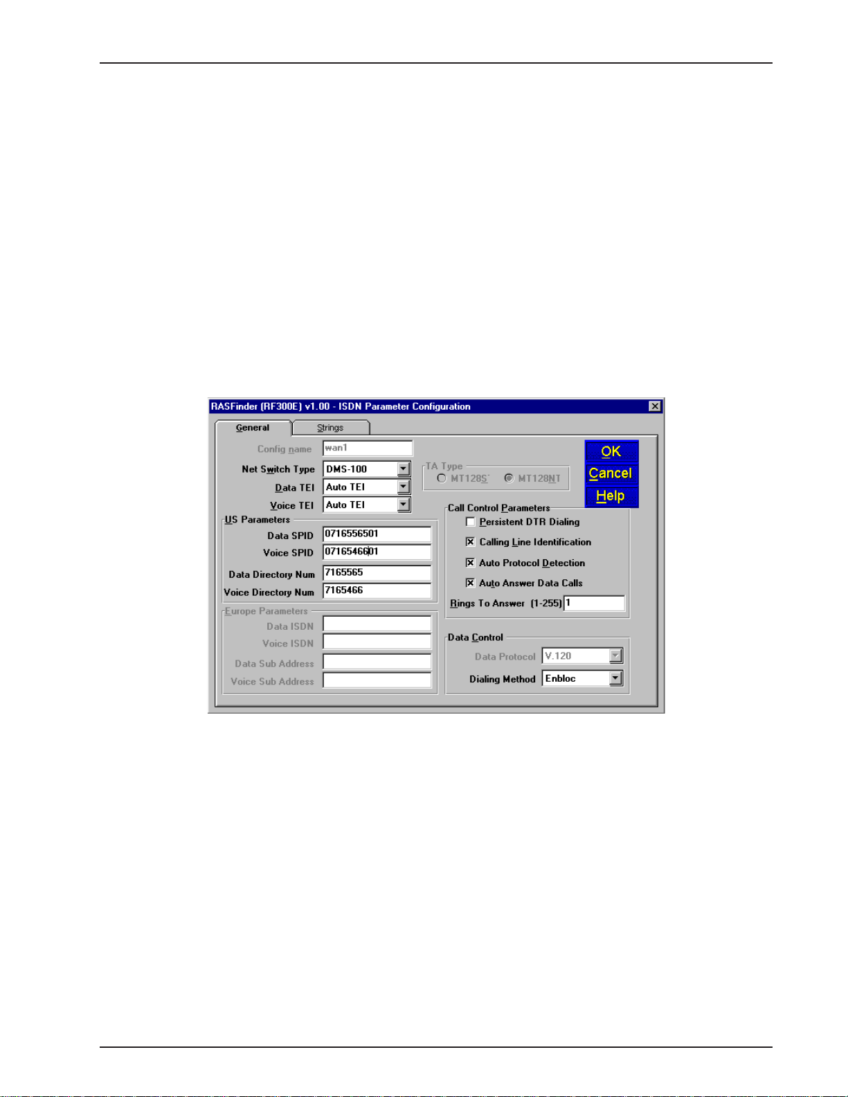
In the ISDN Parameter Configuration dialog box you can define the switch type used by the local
telephone company, data and voice TEI (Terminal Endpoint Identifier), your US or European
Parameters, Call Control Parameters, and Data Control.
At a minimum, you will have to define the switch type and the TEIs and you may have to define the
US or European Parameters if required by your local telephone company . Three switch types are
defined for the US Parameters (DMS100, AT&T5ESS, and NI1), this covers the North American
requirements. The European switch types are VN4 for France, NET3 for Euro, and INS64 for Japan.
The data and voice TEI selections are disabled, auto TEI, or zero to 63. These parameters are
determined by the local telephone company , so all you have to do is enter exactly what is provided in
the your Before You Start Loading your Software listing.
In our RAS Application example in Figure 4-1, the telephone switch at the local telephone company is
a DMS-100 and the local telephone company provisioned the ISDN lines with a data and voice TEI of
Auto TEI. This allows the local telephone company to dynamic assigned the TEIs each time a
connection is made.
Now, for the US or European Parameters which you may or may not have to enter, this depends on
how the local telephone company is provisioning your ISDN connection. If the telephone company
does not require this information, and the default Call Control Parameters and Data Control settings
or OK, you would be done with your ISDN Configuration and ready to set up your Radius security
services.
RF300E/RF310E40
Page 41
Chapter 4 - RASFinder Software
But if your local telephone company requires either SPIDs and/or Directory Numbers for the US
Parameters or ISDNs and Sub Addresses for the European Paramters, you will have to enter these
fields for each WAN port on the RASfinder. A word of caution at this point with respect to entering
this type of information, your need to ensure that these fields are filled in exactly as they are provided
from your local telephone company , because the SPID and DN or ISDN and sub address have to
correspond to the BRI line coming into the RASFinder and the WAN ports assigned to that BRI line.
For if the SPID or ISDN is not on the same BRI line that is provisioned by the local telephone
company, the call will not be completed.
A SPID (Service Profile Identifier) is a 12-digit number that is supplied by your local telephone
company which encompasses the phone number.
A Data or Voice Directory Number (DN) is the telephone number assigned to that B-channel for the
BRI line (telephone line) supplied to you by your local telephone company . If a DN is assigned, then
only the device associated with that WAN port will respond to the call.
In our RAS Application example in Figure 4-1, lets assume that telephone connection is being made
for a US (North American) network. During the provisioning phase of setting up the local ISDN
connection, the local telephone company assigned telephone number 716-5565 to the first B-channel
for BRI 1 connection. This telephone number should correspond to Wan 1 in the ISDN Parameter
Configuration dialog box. The SPID for the first B-channel is 0716556501. The telephone company
also assigned telephone number 716-5466 to the second B-channel for BRI 1 connection. The SPID
for the second B-channel is 0716546601. In our example application, the ISDN Parameter
Configuration dialog box for the US Parameters would contain Data SPID of 0716556501 and Voice
SPID of 0716546601. If you want either of these calls to be directed to the device connected to Wan
1 or Wan 2 you would also enter the telephone number in the Data or Voice Directory Num field. So
for example, if you wanted the Data SPID 0716556501 to be directed to the device on your network
associated with Wan 1, you would enter telephone number 7165565 in the Data Directory Num field
for Wan 1. If you wanted the calls directed to the second B-channel of BRI 1 to go to the device on
your network that is associated with Wan 2, you would enter telephone number 7165466 in the V oice
Directory Num field for Wan 1. When you have finished enterring the parameters for W an 1, you click
the OK button and you will be returned to the dialog box with the ISDN TA Control group. You would
then change to the next Wan number to be configured in the ISDN Parameter Configuration dialog
box. When you have configured all three of the BRI port or the ports connected to the local
telephone company , you can begin setting up your Radius securtiy services.
To enable the Radius security services, you need to establish communications between the Radius
server and the RASFinder. The Radius security service options are defined on the Radius Setup
RF300E/RF310E 41
Page 42

RASFinder RF300E/RF310E User Guide
dialog box. To provide vendor-specific configuration for the Radius server, you need to bring up the
main menu, hit the PPP/SLIP button, and click the RADIUS button in the PPP Port Setup dialog box.
The Radius Setup dialog box enables the RADIUS option, establishes accounting, enables call if
security server is down, assigns a remote address using the RADIUS, provides a window for the
shared secret, and indicates the primary RADIUS server IP address. The new vendor specific
attributes and services that you establish for the RASFinder can not conflict with any standard Radius
attributes or any other custom attributes on the Radius Security Server. The Enable RADIUS option
enables communication between the Radius server and the RASFinder. Enable Accounting option
activates the accounting features which allow the Radius server to track the number of bytes sent
and received, login and logout times, port number, etc. The Allow Call If Security Server Down feature
can be used when the Remote User Data Base Utility is used as a backup database to the Radius
security services. The Assign Remote Address Using RADIUS feature enables the Radius server to
take over the addressing scheme of the WAN ports on the RASFinder.
The Shared Secret is an entry that must be obtained from the Radius network administrator and must
be the same as is used on the Radius security server. The RADIUS Primary Server Address is the IP
address of the Radius security server and in our typical RAS application, this address is 192.168.2.6.
If one or more backup Radius servers are used in your network, then their IP addresses need to be
entered in the Backup Server Address 1, 2, and/or 3 fields.
The Attribute Values Group at the bottom of the Radius Setup dialog box have default values for
each of the three attributes and two services.
The three new attributes are vendor-specific attributes and may have to be added to the Radius
server dictionary. The first attribute is Callback-Delay with a value of 224. The Radius server is set up
with a delay time for calling back the remote user. The Remote User Enter Number Attribute Value
has a value of 225. This attribute specifies a telephone number of where a remote user can be called
back if he/she is not at their usual telephone number provided in their user profile. The remote user
would have to give that new phone number to the Radius network administrator so the RASFinder
will know that the remote user is at a different phone from the one in their user profile.
The Protocol Permissions Attribute has a value of 226 and the values associated with the attribute
are “1” for IP, “2” for IPX, and “3” for Spanning Tree.
The Inbound User Service Type Attribute has a value of “10” and an associated value of “6”. This
attribute enables the remote user to have inbound access to the network only; in other words, this
attribute adds inbound access to the remote user’s profile.
RF300E/RF310E42
Page 43

Chapter 4 - RASFinder Software
The Shell User Service T ype Attribute has a value of “11” and also an associated value of ”6”.
After these new attributes are added to the Radius server and the user profile is established, a
remote user (in our typical RAS application with Radius, Remote User 1, for example) could call into
the RASFinder and identify themselves by their user name and password. Remote User 1, in our
typical application, can initiate a dialup session by entering their User name and password in the DialUp Networking (My Connection) dialog box and the phone number of the WAN port on the
RASFinder that User 1 is going to be connected to. In this application, remote user 1 could dial 7165565 to connect to WAN port number one on the RASFinder.
At this point, Remote User 1 has access to the services on the LAN. For instance, if he/she wanted
to print a report, it could be sent to the printer and printed out as if Remote User 1 was on the local
area network.
RAS Application using Remote User Data Base
The initial software loading process would be the same as for the RAS application using Radius,
except that now instead of setting up Radius parameters, you will assemble a Remote User Data
Base. A typical RAS application using the Remote User Data Base is shown in Figure 4-2.
LAN
Workstation
IP Address
192.168.2.3
Workstation
875-5000
Workstation
User 1
User 2
Workstation
User 3
Network Printer
IP Address
192.168.2.4
Workstation
IP Address
192.168.2.5
Novell File
Server
IP Address
192.168.2.6
RASFinder
IP Address
192.168.2.10
BRI 1
BRI 3
716-5565 {0716556501}
192.168.2.11
716-5466 {0716546601}
192.168.2.12
716-5566 {0716556601}
192.168.2.13
BRI 2
716-5467 {0716456701}
192.168.2.14
716-5567 {0716556701}
192.168.2.15
716-5468 {0716546801}
192.168.2.16
PSTN
Phone
881-3100
Phone
Phone
944-7064
Figure 4-2. RAS Application using Remote User Data Base
During the software loading process when the Default Parameters dialog box is displayed, both IPX
and IP protocols are enabled and a default Ethernet IP address and (subnet) mask are displayed in
the IP LAN group. For this RAS application, you would disable the IPX protocol and then change the
default LAN IP address and mask to the unique IP addressing scheme for your network. The address
assigned to your RASFinder’s Ethernet port can be any address that is recognizable by your
RF300E/RF310E 43
Page 44

RASFinder RF300E/RF310E User Guide
network’s backbone.
In this typical RAS application, the IP network address is 192.168.2.xxx. For the purpose of this
discussion, we are assigning the IP address 192.168.2.10 to the Ethernet port on the RASFinder .
After this address is entered into the IP Address field of the Default Parameters dialog box, the next
six sequential IP addresses (192.168.2.11 thru 192.168.2.16) are assigned to the WAN ports. These
six IP addresses, in the same network (with the Ethernet LAN), are associated with the respective
WAN ports so that when the remote users dial into the WAN port, they always appear (to the rest of
the IP network) at these respective addresses.
At this point, the software will be downloaded to the RASFinder and then you will need to go in
through the main menu to set up your ISDN connection to your Public Switched Telephone Network
(PSTN) and then establish your remote user data base.
To establish your ISDN connection with your local PSTN (either the North American version or the
European version), you may have to enter some ISDN parameters, e.g., switch type used by the
PSTN, SPIDs and Directory Numbers for North America or ISDNs and sub addresses for European
and the Rest of the World (ROW). During the provisioning of the ISDN connection with your local
PSTN, the local telephone company established some ISDN parameters for your local connection. A
space is provided in Before You Start Loading your Software to document these parameters. Now, in
order to load this informtion into your RASFinder, you need to bring up the Main Menu and click on
the WAN button.
From the WAN Port Setup dialog box, click on the Advanced tab to bring up the WAN Port Setup
dialog box with the ISDN TA Control group highlighting wan 1. To establish your ISDN parameters,
click on the Edit button and the ISDN Parameter Configuration dialog box is displayed.
RF300E/RF310E44
Page 45

Chapter 4 - RASFinder Software
In the ISDN Parameter Configuration dialog box you can define the switch type used by the local
telephone company , data and voice TEI (Terminal Endpoint Identifier), your US or European
Parameters, Call Control Parameters, and Data Control.
At a minimum, you will have to define the switch type and the TEIs and you may have to define the
US or European Parameters if required by your local telephone company . Three switch types are
defined for the US Parameters (DMS100, AT&T5ESS, and NI1), this covers the North American
requirements. The European switch types are VN4 for France, NET3 for Euro, and INS64 for Japan.
The data and voice TEI selections are disabled, auto TEI, or zero to 63. These parameters are
determined by the local telephone company , so all you have to do is enter exactly what is provided in
the your Before You Start Loading your Software listing.
In our RAS Application example in Figure 4-2, the telephone switch at the local telephone company is
a DMS-100 and the local telephone company provisioned the ISDN lines with a data and voice TEI of
Auto TEI. This allows the local telephone company to dynamic assigned the TEIs each time a
connection is made.
Now, for the US or European Parameters which you may or may not have to enter, this depends on
how the local telephone company is provisioning your ISDN connection. If the telephone company
does not require this information, and the default Call Control Parameters and Data Control settings
or OK, you would be done with your ISDN Configuration and ready to set up your Radius security
RF300E/RF310E 45
Page 46

RASFinder RF300E/RF310E User Guide
services.
But if your local telephone company requires either SPIDs and/or Directory Numbers for the US
Parameters or ISDNs and Sub Addresses for the European Paramters, you will have to enter these
fields for each WAN port on the RASfinder. A word of caution at this point with respect to entering this
type of information, your need to ensure that these fields are filled in exactly as they are provided
from your local telephone company, because the SPID and DN or ISDN and sub address have to
correspond to the BRI line coming into the RASFinder and the WAN ports assigned to that BRI line.
For if the SPID or ISDN is not on the same BRI line that is provisioned by the local telephone
company, the call will not be completed.
A SPID (Service Profile Identifier) is a 12-digit number that is supplied by your local telephone
company which encompasses the phone number.
A Data or Voice Directory Number (DN) is the telephone number assigned to that B-channel for the
BRI line (telephone line) supplied to you by your local telephone company . If a DN is assigned, then
only the device associated with that WAN port will respond to the call.
In our RAS Application example in Figure 4-2, lets assume that telephone connection is being made
for a US (North American) network. During the provisioning phase of setting up the local ISDN
connection, the local telephone company assigned telephone number 716-5565 to the first B-channel
for BRI 1 connection. This telephone number should correspond to Wan 1 in the ISDN Parameter
Configuration dialog box. The SPID for the first B-channel is 0716556501. The telephone company
also assigned telephone number 716-5466 to the second B-channel for BRI 1 connection. The SPID
for the second B-channel is 0716546601. In our example application, the ISDN Parameter
Configuration dialog box for the US Parameters would contain Data SPID of 0716556501 and Voice
SPID of 0716546601. If you want either of these calls to be directed to the device connected to Wan
1 or Wan 2 you would also enter the telephone number in the Data or Voice Directory Num field. So
for example, if you wanted the Data SPID 0716556501 to be directed to the device on your network
associated with Wan 1, you would enter telephone number 7165565 in the Data Directory Num field
for Wan 1. If you wanted the calls directed to the second B-channel of BRI 1 to go to the device on
your network that is associated with Wan 2, you would enter telephone number 7165466 in the V oice
Directory Num field for Wan 1. When you have finished enterring the parameters for Wan 1, you click
the OK button and you will be returned to the dialog box with the ISDN TA Control group. You would
then change to the next Wan number to be configured in the ISDN Parameter Configuration dialog
box. When you have configured all three of the BRI port or the ports connected to the local telephone
company, you can begin setting up your Radius securtiy services.
RF300E/RF310E46
Page 47

Chapter 4 - RASFinder Software
Before remote users can dial into the network, a user profile has to be set up in the proprietary
remote user database using the Remote User Data base utility . This data base utility is provided with
the RASFinder software. The RASFinder network administrator builds this database by adding
information (for one remote user at a time) via the Add Users dialog box. The user name and
password in this application must be negotiated between the RASFinder administrator and each
remote user.
User names can be up to 39 characters long, with any printable characters; however, no spaces are
allowed within the names. In our dialog box (above), we are using the User Name “User2.” The
letters will appear as all caps in the Users List; however, dial-in applications will treat the user names
as case-insensitive strings, enabling the users to enter their user names as all uppercase, all
lowercase, or a mixture of uppercase and lowercase.
A User Password of up to 7 characters should be given each user. In the Call Back group, the Call
Back option should be enabled (checked) for security purposes. If ONL Y this option is checked, the
remote user would be asked to supply the callback numbers when they dial into the RASFinder. If
Call Back Security Enabled is also checked, the administrator controls the callback numbers through
the Call Back Number field. In our typical application, User 2’s phone number is 875-5000; therefore,
we enter this number in the Call Back Number field. In the Dial In Ports, we have assigned User2 to
WAN Port 2 with phone number 716-5466 assigned to it. This phone number will have to be entered
in the Phone Number field on remote User 2’s dial-up networking (My Connection) dialog box.
After the Add Users dialog box is filled in, you need to click the Rights button which brings up the
User Permissions dialog box.
The User Permissions dialog box enables you to assign protocol’s, user service type(s), time limits,
and time of day for each user to login. The Auto Protocols allow for no auto login, login via Telnet, or
RF300E/RF310E 47
Page 48

RASFinder RF300E/RF310E User Guide
RLogin and then direct the remote user to a specific host. The User Service Types defines how the
remote user is going to be allowed to use the network. For example, a remote user could be allowed
Inbound Permissions using Telnet, or Inbound using Rlogin. The time of day and days in which the
user can access the network are the final items in the User Permissions dialog box. Once this is
established for each user and the user database is loaded into the RASFinder, all the remote users
can dial into the network and access the network resources according to the restrictions/permissions
on this dialog box.
For example, Remote User2 (in our typical application) could initiate a dialup session by merely
entering their User name and password in the Dial-Up Networking (My Connection) dialog box (see
below) after having first set up a New Connection (called “My Connection”) and entering the phone
number of RASFinder WAN port 2 (716-5466), which is assigned to User2.
Once Remote User2 has connected and been authenticated, they have access to the services on the
LAN. For instance, if he/she wanted to print a report, it could be sent to the printer and printed out just
as if Remote User2 was on the local area network.
RF300E/RF310E48
Page 49

Router Application
The second basic application for the RASFinder is LAN-to-LAN routing as shown in Figure 4-3. The
RASFinder is initially configured for a RAS application. To configure the RASFinder for a router
application, you have to change the WAN port addresses to be on a different network from the LAN
port. The remote WAN ports have to be on the same network as the local WAN ports. You would
have to change the Remote Port setup from a RAS application (Client only) to a routing application
(Client or LAN). If your routing application would benefit from having the B-channels of a BRI line tied
together to double your Wan speed, then you would have to enable the MultiLink Point-to-point
(MLPPP) option. Finally , before you can route between LANs you would have to establish the ISDN
parameters for the BRI line connecting the RASFinder to the Public Switched Telephone Network
(PSTN).
LAN
Chapter 4 - RASFinder Software
Workstation
IP Address
192.168.2.3
Network Printer
IP Address
192.168.2.4
Workstation
IP Address
192.168.2.5
Novell File
Server
IP Address
192.168.2.6
RASFinder
IP Address
192.168.2.1
716-5566 {0716556601}
192.168.4.10
BRI 1
716-5467 {0716456701}
192.168.4.10
PSTN
881-3200 {0881320001}
192.168.4.20
881-3201 {0881320101}
192.168.4.20
BRI 1
Remote Office
LAN
IP Address
200.2.9.1
Workstation
IP Address
200.2.9.5
Network Printer
IP Address
200.2.9.6
Workstation
IP Address
200.2.9.7
Workstation
IP Address
200.2.9.8
Figure 4-3. Router Application
During initial software loading, you begin to configure the RASFinder for a routing application. A
typical routing application is shown in Figure 4-3 and will be used as an example in the following
discussion.
When you changed your LAN IP address in the Default Parameters dialog box to your unique LAN
addressing structure, the Remote Addresses in the W AN group will change to sequential addresses
of the LAN port which will not work in a routing application. The initial setup of the software defaults
RF300E/RF310E 49
Page 50

RASFinder RF300E/RF310E User Guide
to a RAS application. The Default Parameters dialog box will not allow you to change the addressing
scheme of the remote WAN ports to your unique addressing structure for your routing application.
Therefore, you have to leave the Default Parameters dialog box set up for a RAS application initially
(during initial software installation and configuration); then later, from the main menu, you can switch
your associated WAN ports from a RAS application to a routing application.
At this point, the software will be downloaded to the RASFinder and then you will need to go in
through the main menu to change the Remote Port setup group from a Client Only (RAS application)
to Client or LAN option for the WAN ports you need for routing, then you will be able to change those
WAN ports to a different network address than your LAN port, and finally, set up your ISDN
parameters for the BRI line connecting the RASFinder to the PSTN.
Before you can change your Wan ports to a different network than the LAN port, you have to click on
the PPP/SLIP (Point-to-Point/Serial Line Internet Protocol) button on the Main menu and the PPP
Port Setup dialog box is displayed with the WAN 1 active. In the Remote Port Setup group in the
lower right of the dialog box, change from the Client only option to the Client or LAN; this disables
RAS, and enables the RASFinder to communicate with either a remote client (PC) or a LAN for
routing. The WANs group must have the Client or LAN enabled for each of the ports that are
providing routing.
RF300E/RF310E50
Page 51

Chapter 4 - RASFinder Software
Now, you can decide if you want the B-channels of the BRI line bonded together or if you want each
B-channel to act alone. To bond the two B-channels of a BRI line together, you click on the Advanced
tab and esure that MLPPP (MultiLink Point-to-Point Protocol) option is active.
If you were to bond BRI 1 line in our Router application in Figure 4-3, you would have to change the
IP addresses (WAN 1 from 192.168.2.2 and WAN 2 from 192.168.2.3 on the Corporate LAN to the
same IP address, for example, you could use 192.168.4.10 for both B-channels. At the remote office
LAN you would then have to change BRI 1 line to say 192.168.4.20.
Now, to configure the RASFinder for the routing application as shown in Figure 4-3 and bonding the
B-channels together, you need to click on the IP button on the Main Menu. The IP Port Setup dialog
box is displayed with the Ethernet tab active showing your LAN IP address.
Next, you need to click on the WAN tab to display the Port Address and Remote Address groups for
WAN 1. Wan 1 is highlighted in the List of WAN ports on the right side of the dialog box. The default
WAN IP addresses will be displayed in the dialog box that were set up during the software loading
and initial configuration of the RASFinder. But, now you can change these addresses to fit your
routing application. Above I stated that we could bond the B-channels together, so here is where we
enter that information. For the Corporate LAN with the B-channels of BRI 1 bonded together and an
IP address of 192.168.4.10, you would enter this in the IP Address field for the Port Address group.
Set up your IP Mask accordingly, and then enter your IP Address for the Remote Office in the IP
Address field of the Remote Address group (192.168.4.20).
RF300E/RF310E 51
Page 52

RASFinder RF300E/RF310E User Guide
Now, you can click on WAN 2 and enter the same information for the Port and Remote Address
groups. This will bond the two B-channels of BRI 1 together .
To set up the remote office LAN, go through the same process except point the WAN ports toward
the Corporate LAN. The remote WAN ports could be set up with an IP address of 192.168.4.20.
Now to establish your ISDN connection with your local PSTN (either the North American version or
the European version), you may have to enter some ISDN parameters, e.g., switch type used by the
PSTN, SPIDs and Directory Numbers for North America or ISDNs and sub addresses for European
and the Rest of the World (ROW). During the provisioning of the ISDN connection with your local
PSTN, the local telephone company established some ISDN parameters for your local connection. A
space is provided in Before You Start Loading your Software to document these parameters. Now, in
order to load this informtion into your RASFinder, you need to bring up the Main Menu and click on
the WAN button.
From the WAN Port Setup dialog box, click on the Advanced tab to bring up the WAN Port Setup
dialog box with the ISDN TA Control group highlighting WAN 1. To establish your ISDN parameters,
click on the Edit button and the ISDN Parameter Configuration dialog box is displayed.
RF300E/RF310E52
Page 53

Chapter 4 - RASFinder Software
In the ISDN Parameter Configuration dialog box you can define the switch type used by the local
telephone company , data and voice TEI (Terminal Endpoint Identifier), your US or European
Parameters, Call Control Parameters, and Data Control.
At a minimum, you will have to define the switch type and the TEIs and you may have to define the
US or European Parameters if required by your local telephone company . Three switch types are
defined for the US Parameters (DMS100, AT&T5ESS, and NI1), this covers the North American
requirements. The European switch types are VN4 for France, NET3 for Euro, and INS64 for Japan.
The data and voice TEI selections are disabled, auto TEI, or zero to 63. These parameters are
determined by the local telephone company , so all you have to do is enter exactly what is provided in
your Before You Start Loading your Software listing.
In our Router Application example in Figure 4-3, the telephone switch at the local telephone company
is a DMS-100 and the local telephone company provisioned the ISDN lines with a data and voice TEI
of Auto TEI. This allows the local telephone company to dynamic assigned the TEIs each time a
connection is made.
Now, for the US or European Parameters which you may or may not have to enter, this depends on
how the local telephone company is provisioning your ISDN connection. If the telephone company
does not require this information, and the default Call Control Parameters and Data Control settings
are OK, you would be done with your ISDN Configuration and ready to start your routing.
RF300E/RF310E 53
Page 54

RASFinder RF300E/RF310E User Guide
But, if your local telephone company requires either SPIDs and/or Directory Numbers for the US
Parameters or ISDNs and Sub Addresses for the European Paramters, you will have to enter these
fields for each WAN port on the RASfinder. A word of caution at this point with respect to entering
this type of information, your need to ensure that these fields are filled in exactly as they are provided
from your local telephone company , because the SPID and DN or ISDN and sub address have to
correspond to the BRI line coming into the RASFinder and the WAN ports assigned to that BRI line.
For if the SPID or ISDN is not on the same BRI line that is provisioned by the local telephone
company, the call will not be completed.
A SPID (Service Profile Identifier) is a number supplied by your local telephone company which
encompasses the phone number.
A Data or Voice Directory Number (DN) is the telephone number assigned to that B-channel for the
BRI line (telephone line) supplied by your local telephone company. If a DN is assigned, then only
the device associated with that WAN port will respond to the call.
In our Router Application example in Figure 4-3, lets assume that telephone connection is being
made for a US (North American) network. During the provisioning phase of setting up the local ISDN
connection, the local telephone company used telephone number 716-5565 for WAN 1 of BRI 1. This
telephone number should correspond to Wan 1 in the ISDN Parameter Configuration dialog box.
The SPID for the first B-channel (WAN 1) could be 0716556501. The telephone company also used
telephone number 716-5466 for the second B-channel (WAN 2) of BRI 1. The SPID for the second
B-channel could be 0716546601. In our example application, the ISDN Parameter Configuration
dialog box for the US Parameters would contain Data SPID of 0716556501 and Voice SPID of
0716546601. If you want either of these calls to be connected to Wan 1 or W an 2 you would also
enter the telephone number in the Data or Voice Directory Num field. So for example, if you wanted
the Data SPID 0716556501 to be directed to Wan 1, you would enter telephone number 7165565 in
the Data Directory Num field for Wan 1. If you wanted the calls directed to the second B-channel of
BRI 1 to go to Wan 2, you would enter telephone number 7165466 in the Voice Directory Num field
for Wan 2. When you have finished enterring the parameters for Wan 1, you click the OK button and
you will be returned to the dialog box with the ISDN TA Control group. You would then change to
WAN 2 and configure the ISDN Parameter Configuration dialog box. When you have configured both
BRI ports connected to the local telephone company , you are now ready to start routing between
LANs.
RF300E/RF310E54
Page 55

IP Setup
The IP Port Setup dialog box enables you to change the IP routing capabilities that were set up
during software installation. This dialog box has three tabs: Ethernet, WAN, and Advanced.
The Ethernet tab enables you to configure two parameters relating to the Ethernet port. For
example, you can change the Ethernet port IP Address and IP mask.
Chapter 4 - RASFinder Software
WAN Tab
If you enable the IP routing master control on the Advanced tab but disable the control on this tab, all
IP packets received or to be transmitted on this WAN port will be discarded. Even if bridging is
enabled, the packets will not get across the link.
The Unnumbered Link option can be selected (checked) for the WAN ports for point-to-point links.
When selected, it disables the Port Address and Remote Address groups. Unnumbered links are
useful only between two routers; in this case, local and remote. When running RIP over a PPP link,
both ends of the link must be either unnumbered or numbered with the same IP subnet. An
advantage of not assigning an IP address to each WAN port is that you conserve valuable network
and subnet numbers.
RF300E/RF310E 55
Page 56

RASFinder RF300E/RF310E User Guide
Remote IP Address defines the IP address for the destination end of a point-to-point link and is
necessary only if the selected WAN port has been enabled for point-to-point operation.
Note: the remote IP address must fall within the same IP network as the local W AN IP address.
The Advanced tab is used to enable IP routing and RIP authentication and defines how the Dynamic
Host Configuration Protocol (DHCP) and Domain Name System (DNS) servers are to be used. This
tab is also used to set up the default route, any filters, and Static Routes.
The Routing option is normally checked; however, if you do not wish to have IP packets routed, then
uncheck this item. If IP routing is disabled and bridging is enabled, IP packets are bridged; i.e., IP
packets are transferred.
The RIP option enables RIP based routing. RIP (Routing Information Protocol) is a protocol used
among routers to exchange routing table information. RIP is the most common protocol used in both
IP and IPX networks. It is also used internally by client workstations in IPX networks to obtain routes
(shortest, or otherwise) to any distant network. RIP based routing should normally be enabled. It can
be disabled, however, if you are using WAN links in Dial on Demand mode. For DOD links, disabling
RIP will reduce traffic on the link as it will also disable periodic RIP broadcasts. RIP routing on a given
port will be automatically turned off when Dial on Demand is enabled on the PPP Port Setup tab for
the WAN port.
The DHCP (Dynamic Host Configuration Protocol) group enables you to set up the WAN ports as
client-only . Then, a PPP client connected to the WAN port will be on the same IP network as the LAN
port of the RASFinder. This feature can save some extra IP addresses that otherwise would have
been taken up by the WAN port. Enabling the Client option allows the RASFinder to dynamically get
an IP address for a PPP client coming up on one of its “Client-only” W AN ports. When this option is
enabled, there must be a DHCP server or a DHCP relay agent on the connected LAN in order for the
RASFinder to acquire an appropriate IP address.
When the router is configured for remote access, the DNS Resolver needs to be enabled so that
applications such as the terminal server will support Domain Names. The dotted decimal IP address
of the Local DNS server should be entered in the field provided.
The Static Routes feature allows a router to direct packets from the local network down a predefined
path (static route) to a remote network. Static routing is normally used when a part of an internetwork
can be reached by only one particular path. Static routes are manually configured routes that specify
the transmission path a data packet must follow based on the data packet’s destination address. A
static route can be setup on the corporate network so that a client pc on the manufacturing network
RF300E/RF310E56
Page 57

Chapter 4 - RASFinder Software
could send a document to the corporate printer.
This static route is shown in the top network in Figure 4-4. A static route can also use an
unnumbered link to provide a particular route for a remote server to appear as a server on the
corporate network. The unnumbered link is shown in the middle network in Figure 4-4.
Corporate
Workstation
IP Address
192.168.2.3
Network Printer
IP Address
192.168.2.4
Radius
Server
IP Address
192.168.2.6
Internet Router
IP Address
192.168.2.220
LAN
Hub
RASFinder
IP Address
192.168.2.10
BRI 1
BRI 3
0716556501 200.2.10.1
0716546601 200.2.10.1
0716556601
0716456701
BRI 2
0716556701 200.2.12.1
0716546801 200.2.12.1
PSTN
200.2.10.2
Phone
881-3100
200.2.12.2
Phone
944-7064
RASFinder or Router
IP Address - 200.1.1.1
Subnet mask - 255.255.255.0
WAN Local - 200.2.10.2
WAN Remote - 200.2.10.1
RAS
or
Router
IP Address - 192.168.2.225
Subnet mask - 255.255.255.224
WAN Local - Unnumbered
RAS
or
Router
Manufacturing
RAS
or
Router
Network
Hub
Tech Support
Network
Hub
Client PC
Remote Network
Publications
Network
Hub
202.1.1.xxx
Client PC
IP Address - 200.1.1.10
Subnet mask - 255.255.255.0
Default Gateway - 200.1.1.1
Manuals Server
IP Address - 192.168.2.226
Subnet mask - 255.255.255.224
Default Gateway - 192.168.2.225
Figure 4-4. Static Routes
In our first example above, where a data packet from the remote client PC on the manufacturing
network is being sent to the corporate printer, a static route would be established on the corporate
RASFinder to have WAN 1 and WAN 2 with network address of 200.2.10.1 and a gateway address of
200.2.10.2, the remote network. The Static Routes Setup dialog box would contain the address of
200.1.1.0 in the IP Address field and a gateway address of 200.2.10.2. The Unnumbered option
would be left unchecked in this example. The IP Address field contains the address of the target host
or network, a PC on the manufacturing network. The Gateway Address is the address of the local
router on the manufacturing network (200.2.10.2) on the next hop toward the target host. The
Address Mask is the IP subnetwork mask (255.255.255.0) of the target host. The Port field is
inactive, greyed out in this example.
This example establishes a static (direct) path for the user on the client pc on the manufacturing
network to send a letter to the corporate LAN and have it printed on the corporate network printer.
The control for this static path is the RASFinder on the corporate LAN.
Now, for our second example of an unnumbered link where we want a server on a remote network to
appear as a device on the corporate LAN. Lets use the example of the Internet router on the
corporate network wanting to provide manuals from the Publications network to Internet users. Lets
say that the Manuals Server on the Publications Network contains released manuals that a customer
can down load from the corporate network. So in order to have the Manuals Server appear on the
Internet router, we need to set up the corporate RASFinder with an unnumbered link and for the
purposes of our example, lets use the middle two WAN ports (W AN 3 and WAN 4). Also, the
Internet router will have a default route of 192.168.2.224 with a subnet Address Mask of
255.255.255.224, and a Gateway Address of 192.168.2.10. The Manuals server would need a
gateway pointing to the corporate RASFinder. The gateway address on the Manuals server could be
192.168.2.225.
RF300E/RF310E 57
Page 58

RASFinder RF300E/RF310E User Guide
So, for this application to work, you need to set up a static route on the Corporate RASFinder of
192.168.2.220 which is pointing at the Internet router. You then need to go into the IP Port Setup
dialog box, select WAN tab, highlight W AN 3, and activate the Unnumbered Link option. Then do the
same thing for WAN 4. When you do this, the Port Address and the Remote Address groups become
inactive. Now, you need to check the PPP/SLIP button on the Main menu and ensure that the
Remote Port Setup group for WAN 3 and W AN 4 are set to Client or LAN.
Now go back to the IP Port Setup dialog box and hit on the Advance tab, then click on the Static
Routes button. This brings up a blank IP Static Routes dialog box, hit the Add button to bring up the
Static Routes Setup dialog box and when you enable the Unnumbered option, the Gateway Address
option becomes inactive.
Now, for the IP Address field we want the address of the Internet router on the Corporate LAN which
in our unnumbered example is 192.168.2.224. In order for the Manuals server on the Publications
network to appear on the Corporate LAN, we need to subnet the Manuals server with an Address
Mask of 255.255.255.224. The Port option identifies the WAN ports on the Corporate RASFinder that
are unnumbered. In our example, WAN 3 and W AN 4 are the unnumbered ports. So you would
develop the Static Routes Setup dialog with WAN 3 as the WAN port and establish a second Static
Routes Setup dialog with the only change from the above dialog box is that WAN 4 is the port
number.
When we click on the OK button for the second Static Routes Setup dialog box, the IP Static Routes
dialog box now displays two examples of static routes.
To complete the Static Route application, the Publications network RASFinder or router, depending
on the type of device used on the network would need a default route of 192.168.2.226 that is looking
at the Manuals Server. The Ethernet port IP address could be 192.168.2.225 with a net mask of
255.255.255.224.
RF300E/RF310E58
Page 59

Filters
Chapter 4 - RASFinder Software
The network administrator can set up filters on the RASFinder for better control. Filtering can be used
when you want to block all packets originating from a specific destination (called source address
filtering) or all packets heading for a particular destination (called destination address filtering). Filters
can be set up to exclude packets of a particular protocol (TCP or UDP) or any particular field in a
LAN packet. The IP Filtering Setup dialog box lists the port, address, or Internet Control Message
Protocol (ICMP) filtering for the IP protocol.
Initially, the filtering list window, i.e., the window area that displays the Type, Port, Protocol, and
Protocol Port information is blank. This information is displayed in the window when the Add/Edit IP
Port or Address Filter dialog box is filled out.
Note: When filters are installed, the RASFinder needs to do extra processing (i.e., it needs to look
into each packet that has to be routed or bridged). Thus, installing too many filters may lead to
performance degradation.
Port filtering filters or forwards IP packets based on their specific purpose; i.e., whether they are
Telnet (TCP based) or TFTP (UDP based) packets. Address filtering filters or forwards packets
based on their source or destination IP address. Separate filtering support is provided for specific
kinds of received ICMP packets.
The filtering list window on the Port Filtering tab (above) displays the filter T ype, the physical Port
(LAN, or one of the WAN ports), the Protocol (TCP or UDP), and the Protocol Port. On the Address
Filtering tab (not shown), the Protocol and Protocol Port columns are replaced by IP Address.
To add or edit a filter listing, the Add/Edit IP Port (Address) Filter dialog box is used. This dialog
box enables you to create an entry which is then displayed in the filtering list window. In the example
Add/Edit IP Port Filter dialog box, the protocol that is going to be filterred is TCP, the physical port on
RF300E/RF310E 59
Page 60
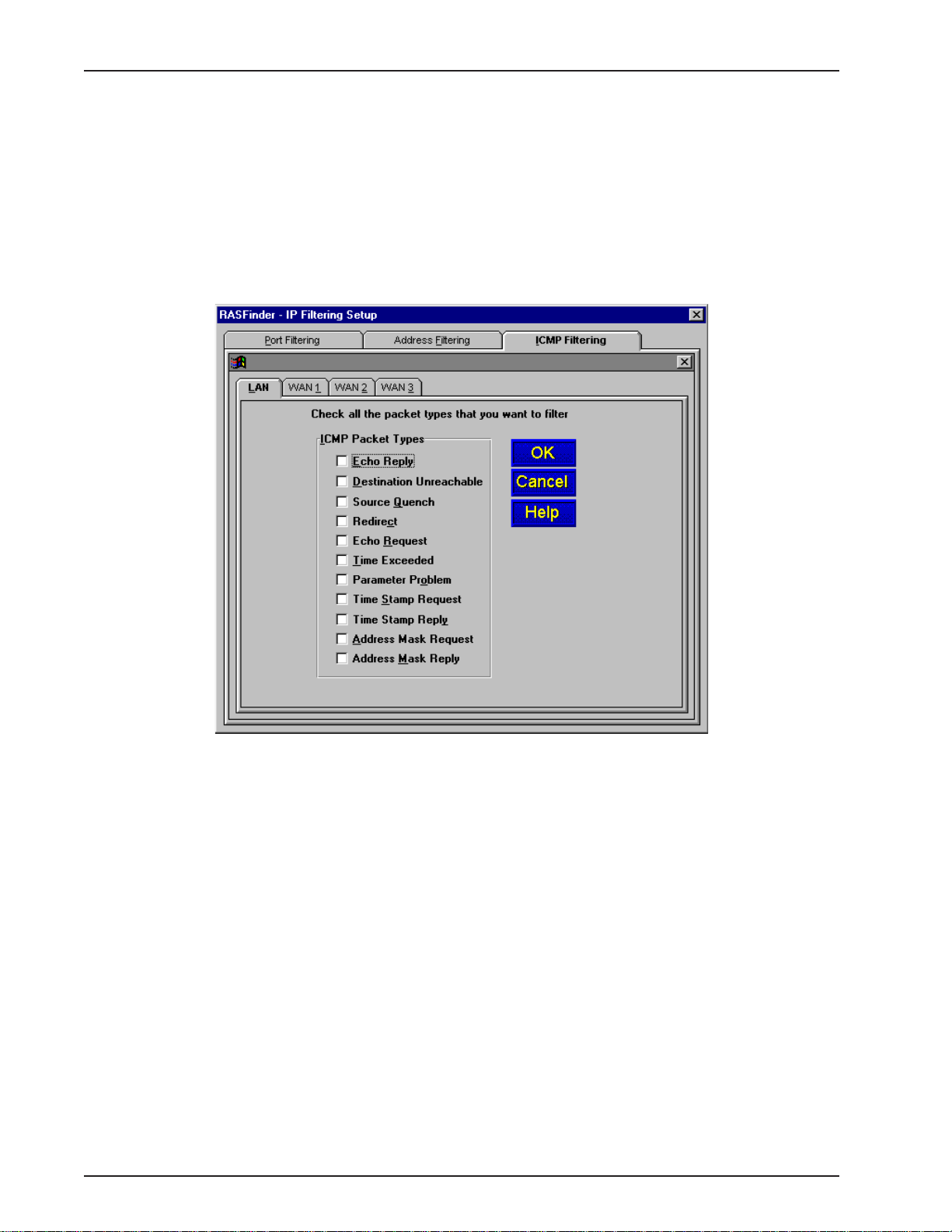
RASFinder RF300E/RF310E User Guide
which the filtering is going to take place is the LAN port, the protocol port is telnet which translates
into protocol port number 0023 in the filtering list window, and the filter type is Filter on Destination
Port which means to drop all IP packets whose destination protocol port is telnet.
Address filtering uses the IP address in the IP Address field (example, packets with address
192.168.2.40), applies filtering to the physical port listed in the Physical Port field (LAN), and if the
Filter T ype is Filter on Destination Address that means that all packets with an IP address of
192.168.2.40 that are destined for the LAN port are blocked.
ICMP filtering provides separate filtering support for specific kinds of received ICMP packets. ICMP
filtering is used in IP networks as an internal protocol for nodes to exchange control and diagnostic
information. Applications normally do not use ICMP filtering for any purpose.
You can select ICMP filtering on your LAN or WAN ports and the type of filtering on each port by
choosing the filtering type from the ICMP Packet Types list.
RF300E/RF310E60
Page 61

IPX Setup
The IPX Virtual Port Setup dialog box is used to control the four frame types and set up the WAN
ports of the RASFinder. The Advanced tab opens an IPX general setup window used to enable or
disable IPX routing and autolearn of Ethernet network numbers.
In IPX based networks using Ethernet, LAN segments can support the use of four different Ethernet
frame formats over the same physical link (provided each frame type has a unique network address
as a virtual port).
The Wan tab allows you to enable or disable IPX routing on the W AN ports and change the network
number for the WAN ports. The IPX WAN network number has to be the same on both ends of the
link and must be unique throughout the internetwork. If a WAN port is configured in a point-to-point
operation, both WAN network numbers have to be the same and unique.
Chapter 4 - RASFinder Software
NetBIOS, when enabled, enables the transport of Novell encapsulated NetBIOS packets on the
specified virtual IPX port. Refer to Novell documentation regarding NetBIOS operation over NetWare
based LANs.
The Advanced tab controls the master routing of the protocol and auto learn of Ethernet network
numbers, defines the broadcast name of the RASFinder, and enables IPX filtering.
RF300E/RF310E 61
Page 62

RASFinder RF300E/RF310E User Guide
If bridging of IPX packets is desired, IPX routing must be disabled and frame type support for the
frame type must be enabled.
If there is a server on the local segment, then IPX network number auto learn should be enabled. If
there is no server, or if for some reason the RASFinder comes up before the server does, the
RASFinder will default to some random network numbers after a short period of time.
IPX Filters
The network administrator can set up filters on the RASFinder for better control. IPX packet filtering
can be set up to selectively filter or forward packets based on the IPX address.
Filtering can be used when you want to block all packets originating from a specific destination
(called source address filtering) or all packets heading for a particular destination (called destination
address filtering). Filters can be set up to exclude packets of a specific port. The IPX Filtering Setup
dialog box lists the filter type, port, and IPX address. Initially , the filtering list window, i.e., the window
area that displays the Filter T ype, Port, and IPX Address information is blank. This information is
displayed in the window when the Add/Edit IPX filter dialog box is filled out.
Note: When filters are installed, the RASFinder needs to do extra processing (i.e., it needs to look
into each packet that has to be routed or bridged). Thus, installing too many filters may lead to
performance degradation.
The Add or Edit IPX Filter dialog box allows you to enter a network number and node number, and
define a socket number, physical port, and filter type. The Network Number defines the physical port
which is defined by turning off AutoLearn Ethernet Network Numbers option in the IPX V irtual Port
Setup dialog box under the Advanced tab. The Node Number is a 12-digit alphanumeric MAC
Address of the Ethernet NIC that is providing your Ethernet interface. The Node Number is defined in
the IP Configuration dialog box under the Adapter Address in the Ethernet Adapter Information group.
The Adapter Address is presented with dashes between each set of two alphanumeric digits. These
dashes can not be used in the Node Number . The IP Configuration dialog box is accessed from a
DOS prompt by enterring winipcfg.
The socket number, physical port, and filter type are provided in drop down lists. Three socket
number selection are provided; NCP, RIP, and SAP. The physical port lists the available port for
which filtering can be accomplished; LAN and the WAN ports. The filter type defines whether you are
going to forward or filter depending on the source or destination address.
RF300E/RF310E62
Page 63

Spanning Tree Setup
This dialog box lets you configure the parameters for transparent bridging or bridging using Spanning
Tree Algorithm as specified in IEEE 802.1d standard. T ransparent bridging occurs between two
remote Ethernet LANs.
Spanning Tree Algorithm is a protocol specified by the IEEE 802.1d standard for use by bridges to
perform bridging. Bridges implementing this protocol interact with each other so as to prevent
bridging-loops in an internetwork with redundant links to the same networks. This algorithm also
allows for automatic use of alternative routes (provided there are redundant paths to the destination)
in case the original route is unavailable for some reason.
Chapter 4 - RASFinder Software
Bridging needs to be enabled to support networking protocols such as NetBIOS. However, if you are
using only IP and IPX, the RASFinder will operate more efficiently if you leave bridging disabled.
The Filters button enables the construction of a filtering database. Packets whose Ethernet source
address or destination address is not found in the filtering database will either be filtered or
forwarded, depending on the setting of the Default Action field, with a default setting of “forward.”
Filtering can be used when you want to block all packets originating from a specific destination
(called source address filtering) or all packets heading for a particular destination (called destination
address filtering). Filters can be set up to exclude packets of a specific port. The Spanning Tree
Filtering Setup dialog box lists the filters by filter type, port, and Ethernet address. Initially , the
filtering list widow, i.e., the window area that displays the Filter Type, Port, and Ethernet Address
information is blank. This information is displayed in the window when the Add/Edit Spanning Tree
Filter dialog box is filled out.
Note: When filters are installed, the RASFinder needs to do extra processing (i.e., it needs to look
into each packet that has to be routed or bridged). Thus, installing too many filters may lead to
performance degradation.
The add or edit Spanning Tree Filter dialog box allows you to enter the Ethernet address (for
example 00015345678) to which you want to apply filtering, the physical port (WAN 1) on which the
filtering is going to be applied, and the filter type in our example of Filter Destingation Address.
RF300E/RF310E 63
Page 64

RASFinder RF300E/RF310E User Guide
This means that all packets with a destination address of 00015345678 going to WAN 1 are dropped.
RF300E/RF310E64
Page 65

WAN Port Setup
The W AN Port Setup dialog box controls how each WAN port is configured. The options at the top
of the dialog box (i.e., Port Enable, Needs Dial Backup, and the Scripting options) can be assigned to
each port listed in the Wans group in the lower right part of the dialog box. The Connection Method
can be set for either Answering or Dialing for each port listed in the Wans group. When the dialing
option is selected, the Asynchronous Gateway Server [AG Server] and Terminal Server groups
become inactive. To configure a WAN port for dial backup, you need to click on the Needs Dial
Backup option and then click on the Backup Port tab and enter the call back phone number, WAN
port, and priority of the call.
Chapter 4 - RASFinder Software
If a WAN port Needs Dial Backup in case it loses carrier (i.e., the Carrier signal, DCD, goes down),
then Wan 6 is dedicated for this purpose. Therefore, five of the six WAN port can be used for dial
backup. When the Needs Dial Backup option is selected, the call back number needs to be enterred
in the Dial Number field of the Backup Parameters. The WAN port number has to be specified and
the priority of the call back has to be specified. The call back priority ranges from No Priority to four.
The Script button provides access to the scripting options. The Script Dialog menu enables you to
edit, compile and download scripts. A script file (a text file containing a sequence of commands; refer
RF300E/RF310E 65
Page 66

RASFinder RF300E/RF310E User Guide
to Appendix B) can be used to automate certain RASFinder operations. The Script Enable or
Restart Script On Communications Failure option can be used to either start scripting or restart a
script upon failure.
The RASFinder has built-in support for Multi-Tech Communication Services Interface Server (MCSI,
NASI, NCSI, or AG server) if every asynchronous communication line across the internetwork has a
unique MCSI name. If you set the Connection Method for Answering, the Asynchronous Gateway
Server (AG Server) group becomes active, enabling you to set the General Name and Specific
Name of the interface corresponding to that specific WAN Port. The name of the AG Server is
assumed to be the same as the IPX router name (or at least the first eight characters of the Router
Name entered on the Default Parameters dialog box during initial configuration). The General Name
can be any 8 alphanumeric characters (with no question marks) and the Specific Name can be any
14 alphanumeric characters (with no question marks).
Setting the Connection Method for Answering also activates the Terminal Server group, where you
need to enter, in the field provided, the dotted decimal IP Address of the default T elnet server.
From the Advanced tab, you can define the parameters for each WAN port, i.e., whether it is an
ISDN parameter or a modem parameter. In defining the ISDN TA Control parameters, you highlight
the WAN number and click on the Edit button. To define the modem parameters for the five out of six
modems, you enter the modem string in the appropriate String number corresponding to the WAN
port selected the Wan tab.
When you select the Wan port in the ISDN TA Control group and click on the Edit button, the ISDN
Parameter Configuration dialog box is displayed with the Wan port number displayed in the Config
name field. The Config name field is greyed out so that it can not be changed.
RF300E/RF310E66
Page 67

Chapter 4 - RASFinder Software
This dialog box displays the network switch type and the US Parameters or the Europe Parameters,
depending on the switch type selected. In the first example (above), the default US Parameters are
displayed and are available for editing purposes. The Net Switch Type is also unavailable as it is the
switch type that was defined for this particular configuration.
General Parameters
Data TEI (Terminal Endpoint Identifier) - You may have received a fixed TEI (a number from 0 to 63)
from your provider; if so, then select that number from the list in the Data TEI box. However , if the
central office switch assigns a dynamic TEI each time your RASFinder connects to the network, then
leave it set to the default, “Auto TEI.” If you have multiple RASFinders attached to a network
terminator bus, you may want to set the Data TEI to ”Disabled.”
V oice TEI - You may have received a fixed TEI (a number from 0 to 63) from your provider; if so, then
select that number from the list in the Voice TEI box. However, if the central office switch assigns a
TEI each time your RASFinder connects to the network, then leave it set to “Auto TEI.” Again, if you
have multiple RASFinders attached to a network terminator bus, you may want to set the Voice TEI
to “Disabled.”
US Parameters
The US Parameters group includes the Data SPID, Voice SPID, the data Directory Number (DN),
and the voice DN. The SPIDs and Directory Numbers may not be required by your service provider;
but, if they are required, the fields are defined below.
Data SPID (Service Profile Identifier) - Enter the Data SPID, if required, that was assigned by the
local phone company for the specific BRI line to which the RASFinder is attached. The Data SPID
string can have up to 20 characters. For DMS-100 switches, any ASCII character except the
underline (_) is valid; For NI-1 and AT&T switches, only the digits 0-9 are valid.
V oice SPID - Enter the Voice SPID, if required, that was assigned by the local phone company for
the specific BRI line to which the RASFinder is attached. The Voice SPID string can have up to 20
characters. For DMS-100 switches, any ASCII character except the underline (_) is valid; For NI-1
and AT&T switches, only the digits 0-9 are valid.
Data Directory Number (DN) - The data DN is a telephone number the ISDN service provider
assigns, if required, to the RASFinder at subscription time; this can be a string of up to 24 characters.
V alid characters are 0-9, the * character, and the # character.
RF300E/RF310E 67
Page 68

RASFinder RF300E/RF310E User Guide
V oice DN - The voice DN is a telephone number the ISDN service provider assigns, if required, to the
RASFinder at subscription time; this can be a string of up to 24 characters. Valid characters are 0-9,
the * character, and the # character.
European Parameters
The Europe Parameters group includes the Data ISDN, Voice ISDN, the Data Sub Address, and the
voice Sub Address. The Data and Voice ISDNs and Sub Addresses may not be required by your
service provider. If the ISDNs and Sub Addresses are required, the fields are defined below.
Data ISDN - Enter the Data ISDN, if required, that was assigned by the local phone company for the
specific BRI line to which the RASFinder is attached. The Data ISDN string can have up to 20
characters. If the switch type is NET3, the Data ISDN is not used.
V oice ISDN - Enter the Voice ISDN, if required, that was assigned by the local phone company for the
specific BRI line to which the RASFinder is attached. The V oice ISDN string can have up to 20
characters. If the switch type is NET3, the Voice ISDN is not used.
Data Sub Address - The Data Sub Address is a telephone number the ISDN service provider
assigns, if required, to the RASFinder at subscription time; this can be a string of up to 24 characters.
V alid characters are 0-9, the * character, and the # character.
V oice Sub Address - The Voice Sub Address is a telephone number the ISDN service provider
assigns, if required, to the RASFinder at subscription time; this can be a string of up to 24 characters.
V alid characters are 0-9, the * character, and the # character.
Call Control Parameters
Persistent DTR Dialing - Data Terminal Ready (DTR) normally goes high when a communication
program starts or is ready to dial. A high DTR on the serial port indicates that your computer or
terminal is ready to communicate with the RASFinder. The Persistent DTR Dialing function built into
the RASFinder enables the RASFinder to automatically redial the telephone number of the ISDN
service provider whenever DTR is high and there is no active call on the serial port. You can either
enable or disable this feature (the default for this function is “disabled” or unchecked).
Note: You can use the key combination, “Alt-P” to check or uncheck this function.
Calling Line Identification (CLI) - When you check this function, the RASFinder identifies (for ISDN
data calls only) whether the two endpoints of a connection are enabled or disabled for the purposes
of RING messages. If the Calling Party Number is included in the incoming SETUP message for a
given call, the RING message will display it, together with the Called Party Number, in the following
format: “FM: 5552000 TO: 5551000.” If the Called Party Number is not included in the SETUP
message, the RING message will show only the Calling Party Number as follows: “FM: 5552000.” If
neither number is included, the RING message will contain no additional information. The default for
this parameter is “enabled” or checked.
RF300E/RF310E68
Page 69

Chapter 4 - RASFinder Software
Note: you can use the key combination of “Alt-D” to check or uncheck this function.
Auto Protocol Detection - You should leave this function disabled (unchecked) because we set the
Data Protocol in the Data Control group to “MLPPP” and do not use any of the other protocols listed
there.
Auto Answer Data Calls - You can enable this function if you want your RASFinder to answer
automatically all incoming data calls (this option does not affect the analog port). If you do enable the
Auto Answer function, you should also set the Rings To Answer function unless you want to leave it at
the default selection which is one ring before it answers. (Selecting either “0” or “1” causes it to
answer after the first ring.)
Data Control
Data Protocol - As mentioned above (in Auto Protocol Detection), we leave this function set to
MLPPP, which uses both B channels (each at rates of up to 64 Kbps per channel) providing an
aggregate data transmission speed of 128 Kbps, maximum.
Dialing Method - The default is “Enbloc,” which is used for most ISDN dialing; however, if your
RASFinder is on a private network you can switch to the “Overlap” dialing method for establishing a
data call on the ISDN line.
Strings
The Strings dialog box allows you to add additional initialization commands for your ISDN
configuration. The AT commands for your ISDN String are found in Attachment D of this User Guide.
RF300E/RF310E 69
Page 70

RASFinder RF300E/RF310E User Guide
Point-to-Point Setup
The PPP Port Setup dialog box controls the W AN port protocol, dial on demand, and remote port
setup. The WAN port protocol can be either Point-to-Point Protocol (PPP) or Serial Line Internet
Protocol (SLIP). Of these two protocols, PPP is the more robust as it enables the endpoints to
negotiate the use of the link and protocol parameters in a standardized way and also enables for
standardized encapsulation of the packets. SLIP is an older protocol which requires manual
authentication using a script.
PPP is the default protocol. The PPP software in the RASFinder internally negotiates the use of a
suitable authentication protocol (PA P or CHAP) with the remote router or remote access client
software. When either P A P or CHAP (or both) is enabled, the RASFinder expects the peer (the client
on the other side of the WAN link) to be configured with a User Name and Password combination that
is in the RASFinder’s User Database. The User Name and Password are both ASCII character
strings that can be up to 30 characters long. However, for router-to-router connections, authentication
is normally not used and the User Name and Password fields are empty .
If SLIP is to be used on one of the WAN ports, then select the SLIP Enable option on the
corresponding tab and PPP will be disabled automatically. If the TCP/IP header is to be compressed
using VJC compression, then check the CSLIP (Van Jacobson Compression) option. (Note: on
answering WAN ports, the RASFinder can detect the type of connection -- PPP or SLIP.)
You can set up the RASFinder to bring down the connection on the WAN link when there is no real
data traffic on the line; the router will then automatically bring up the WAN link when data is available
to go across the link.
In the Remote Port Setup group, the Client only option saves IP addresses in a RAS application
because the remote node (a dial-in client) becomes a virtual extension of the Ethernet LAN. For
Routing, however, you must check the Client or LAN option, in which case there will be no saving of
IP addresses on the WAN ports.
RF300E/RF310E70
Page 71

Applications
In addition to local configuration, the RASFinder supports various applications that enable remote
viewing and changing of the configuration from anywhere on the connected internetwork. To manage
these applications, click Others on the Router Setup menu.
The Applications Setup dialog box appears.
Chapter 4 - RASFinder Software
Verify that the desired applications are enabled (checked). The default condition is all applications are
checked. To disable a given application, click to uncheck the check box and disable support.
For more information on using these remote configuration applications, click the on-line Help button
or refer to Chapter 7, Remote Configuration and Management.
Diagnostics
The RASFinder is equipped with a built-in diagnostics utility that can be accessed by a PC cabled
directly to the command port (remote users cannot access the diagnostics). Click the Built-in T est
button on the Router Setup menu and the Diagnostics dialog box is displayed.
In the Test Port group, select the either the WAN or Ethernet button you want to test. If you choose
the WAN button, you can then select a specific WAN port to test by highlighting the WAN number in
the drop down window. Click the Test button to start the test.
For additional details and parameters about specific fields in the Diagnostics dialog box, click the
on-line Help button.
RF300E/RF310E 71
Page 72

RASFinder RF300E/RF310E User Guide
RF300E/RF310E72
Page 73

Remote Access Device
Chapter 5 - Client Setup
Page 74

RASFinder RF300E/RF310E User Guide
Introduction
The information provided in this chapter enables multiple users to configure their PCs to access the
LAN through a RASFinder. The procedures are divided into two sections, based on operating
platform. The first section covers configuration of Windows 98/95 PCs, and the second section
covers configuration of Windows NT (4.0 Workstation) PCs.
Before you Begin
Before you begin the client setup process, read through the following requirements:
RASFinder
The RASFinder was configured by the administrator who, while installing the software, determined
that the RASFinder would either automatically assign Internet (IP) addresses, or require that they be
assigned manually to each client PC. Also, the administrator assigned an IP address to the
RASFinder’s Ethernet port, and assigned user names and passwords to the WAN links. All these
factors play a role in client configuration. Make certain that you are aware of the decisions made prior
to setting up client PCs.
PC
To access the RASFinder, your PC must have communications capability including hardware such as
a Dial Up Network Adapter/modem and any necessary software.
Make certain that your Dial Up Network Adapter IP addressing is dynamically assigned (default). If it
is, then the only information you may be required to obtain is the IP address of your organization’s
Domain Name Server (DNS) - if DNS has been enabled on the IP Setup dialog box, Advanced tab.
Note: In cases where the IP address has been manually assigned, you will need to know the IP
address of the RASFinder (Gateway address) in addition to the organization’s Domain Name.
Checklist
A checklist has been provided towards the end of each procedure (Step 16). This checklist is
included in the setup so that you can record all the pertinent information required for the connection
between your PC and the RASFinder. Keep this as a reference for future upgrades.
RF300E/RF310E74
Page 75

Configuring in Windows 98/95
Perform the following steps to set up your Windows 98/95 PC:
Note: All of the hardware and screens used in this section are intended as examples only. Please
select options appropriate to your system.
1. Click Start | Settings | Control Panel and then double click the Network icon.
The Network dialog box (Configuration tab) is displayed which shows all the components (i.e.,
clients, adapters, protocols, and any services) installed on your PC.
Chapter 5 - Client Setup
2. If TCP/IP is listed, proceed to step 3; otherwise, refer to Installing TCP/IP (Win98/95), at the end
of this section.
RF300E/RF310E 75
Page 76

RASFinder RF300E/RF310E User Guide
3. Check for binding between the adapter and TCP/IP. In the Network dialog box, click your
Ethernet adapter to select it, then click Properties to display the Adapter Properties window.
4. Click the Bindings tab, then if necessary click the box to the left of TCP/IP so this entry is
enabled (checked). When you are finished, click OK to return to the Network dialog box.
Note: There may be other protocols listed and enabled under your Ethernet adapter . This does
not affect the TCP/IP protocol. Rather, it simply means your computer will accept messages
using those protocols as well as TCP/IP.
RF300E/RF310E76
Page 77

Chapter 5 - Client Setup
5. Select TCP/IP, then click Properties to open the TCP/IP Properties window.
6. Select the IP Address tab.
The IP addressing method depends on how your RASFinder’s DHCP Server option was
configured. If DHCP Server is active, your IP address is issued automatically from an external
DHCP server located on the LAN. If your network administrator did NOT activate DHCP Services
on the RASFinder, the IP address assigned to the client will be the same as the WAN’s remote IP
address or may be assigned by a Radius server.
Verify the RASFinder/DHCP status with your network administrator, then proceed to step 7 for
DHCP assigned addressing, or to step 8 for manual addressing.
Note: The RASFinder Dynamic Host Configuration Protocol (DHCP) option is enabled on the IP
Port Setup, Advanced tab.
7. If DHCP Services are active on the RASFinder (default), verify that the Obtain an IP address
automatically option is selected. You are done; go to step 17 to reboot your PC and attempt to
open an Internet session.
8. If DHCP Services are NOT active on the RASFinder, you may be required to manually enter your
IP address. In most cases, dynamically assigned addressing is the best alternative. The only
exception would be if only one specific WAN port is accessed or if Radius is assigning an IP
address based on the user logging into the Radius server. Select manual addressing by clicking
the Specify an IP address option. The IP Address and Subnet Mask fields become active.
RF300E/RF310E 77
Page 78

RASFinder RF300E/RF310E User Guide
Remove the default IP address (if any) and begin typing the new address. This address is
entered in dotted decimal notation and is comprised of four groups (octets) separated by periods
or “dots.” If a group has fewer than 3 digits, type the necessary digits and press the space bar to
move to the next group. When you are finished, verify that the IP address is identical to the IP
address you were given for your PC.
RF300E/RF310E78
Page 79

10. Click the Gateway tab.
Chapter 5 - Client Setup
1 1. In the New gateway field, enter the IP address of the RASFinder’s Ethernet port and click Add.
The new gateway address is displayed in the list of Installed gateways.
RF300E/RF310E 79
Page 80

RASFinder RF300E/RF310E User Guide
12. Click the DNS Configuration tab. Verify that Enable DNS is selected (checked).
13. In the Host field, enter your user name (e.g., jerry).
14. In the Domain field, enter your company’s domain name (usually the company name followed by
one of the following extensions: .com, .edu, .gov , .org, .mil, or .net. For example, multitech.com).
15. In the DNS Server Search Order group, place the cursor in the first group of the address field
and type the IP address of your LAN’s DNS server (provided by your network administrator).
Click Add and the new address is displayed in the list below the address field.
Your network may have more than one DNS server, allowing you to use a secondary DNS server
if the primary DNS server is not available. If this is the case, add the IP address of the secondary
DNS server using the same procedure as with the first.
Note: The address that is displayed first (at the top) of the list is the primary server (the first one
searched). You can “drag and drop” the items in the list, if necessary, until the primary DNS
server is listed first.
When this is done, click OK. You are returned to the Network dialog.
16. In the Network dialog box, Click OK. You are returned to the Control Panel.
Use the following checklist to record all the configuration settings for future use:
RF300E/RF310E80
Page 81

Configuration Checklist
Chapter 5 - Client Setup
IP Address (PC)
IP Address (RASFinder)
. . .
. . .
Host (User Name)
Domain
DNS Server Address
. . .
Network Adapter
(Manufacturer/Model Number)
17. Reboot the PC for changes to take effect.
At this point your client setup is complete. Test your setup by following steps 18 and 19. If you
encounter problems, contact your administrator.
18. Initiate an Internet session by double-clicking on your browser icon, or try to FTP a file.
Note: The RASFinder operates transparently, so there should not be a need for any special
settings on your IP applications (i.e., browser , Telnet, or FTP).
19. To further validate your connection to the RASFinder, “Ping” the IP address of the RASFinder.
RF300E/RF310E 81
Page 82

RASFinder RF300E/RF310E User Guide
Installing TCP/IP (Win98/95)
If TCP/IP is not already installed, perform the following steps:
Note: For this procedure you may need your Windows installation disks or CD ROM.
1. In the Network dialog box, click Add. The Select Network Component T ype dialog box is
displayed with a list of installation options.
2. Select Protocol and click Add. The Select Network Protocol dialog box is displayed with
protocol options.
3. In the Manufacturers list click the manufacturer option (Microsoft in the example) to highlight it. A
list of available protocols will appear in the Network Protocols list.
4. In the Network Protocols list, select TCP/IP and click OK.
5. Exit the add option. Click the OK button.
Note: If Windows does not find the necessary files on the hard drive, click Have Disk and follow
the on-screen instructions for loading TCP/IP from the installation disks/CD-ROM.
6. Reboot your PC for changes to take effect.
7. Click Start | Settings | Control Panel and double-click the Network icon to return to the
Network dialog box. Return to step 3 of the Configuring in Windows 98/95 and continue with
the client setup procedure.
RF300E/RF310E82
Page 83

Configuring in Windows NT
Perform the following steps to set up your Windows NT workstation PC:
Note: All of the hardware and screen samples in this section are intended as examples only. Please
select options appropriate to your network.
1. Click Start | Settings | Control Panel.
Chapter 5 - Client Setup
Double click the Network icon.
2. The Network dialog box is displayed. Click the Protocols tab.
A list of protocols currently present on your PC is displayed. Check the installed protocols. If you
find TCP/IP Protocol listed, proceed to step 4. If TCP/IP is not listed, you must install it prior to
proceeding. Refer to Installing TCP/IP (WinNT) at the end of this section.
Click the Bindings tab.
RF300E/RF310E 83
Page 84

RASFinder RF300E/RF310E User Guide
3. The Bindings tab is displayed.
4. In the Show Bindings for drop down list, select all adapters. A list of all adapters is displayed.
5. Double click the entry for your Ethernet card adapter to expand the list of bindings. Verify that
TCP/IP Protocol is included in the bindings below your adapter .
Note: There may be other protocols in the list under your Ethernet adapter. This does not affect
the TCP/IP protocol. Rather, it simply means your computer will accept messages using those
protocols as well as TCP/IP.
6. Click the Protocols tab.
RF300E/RF310E84
Page 85

Chapter 5 - Client Setup
7. In the Network Protocols list select TCP/IP, then click Properties. The Microsoft TCP/IP
Properties dialog box is displayed.
8. Click the IP Address tab.
The IP addressing method depends on how your RASFinder’s DHCP Server option was
configured. If DHCP Server is active, your IP address is issued automatically. If your network
administrator did NOT activate DHCP Services on the RASFinder, you will have to assign your IP
address manually .
Verify the RASFinder/DHCP status with your network administrator, then proceed to step 9 for
DHCP assigned addressing, or to step 10 for manual addressing.
9. If DHCP Services are active on the RASFinder (the default), verify that the Obtain an IP address
from a DHCP server option is enabled (checked). At this point, you are done. Go to step 20 and
attempt to open an Internet session.
10. If DHCP Services are NOT active on the RASFinder , you may have to manually enter your IP
address. Select manual addressing by clicking the Specify An IP Address option. The IP
Address and Subnet Mask fields become active.
RF300E/RF310E 85
Page 86

RASFinder RF300E/RF310E User Guide
11. In the IP Address field, type the IP address assigned to your PC.
Remove the default IP address (if any), and begin typing the new address. This address is
entered in dotted decimal notation and is comprised of four groups (octets) separated by periods
or “dots.” If a group has fewer than 3 digits, type the necessary digits and press the space bar to
move to the next group. When you are finished, verify that the IP address is identical to the IP
address you were given for your PC.
12. In the Subnet Mask field, type the subnetwork mask assigned by your administrator. When you
are finished, verify the new mask.
13. In the Default Gateway field, type the IP address of the gateway assigned to your LAN. When
you are finished, verify the new gateway .
RF300E/RF310E86
Page 87

Chapter 4 - RASFinder Software
14. Click the DNS tab. The Domain Name System (DNS) properties are displayed.
15. In the Host Name field, type your user name (e.g., jerry).
16. In the Domain field, enter your company’s domain name (usually the company name followed by
one of the following extensions: .com, .edu, .gov , .org, .mil, or .net. For example, multitech.com).
17. In the DNS Server Search Order group, click Add. The TCP/IP DNS Server dialog box is
displayed.
18. In the DNS Server field, place the cursor in the first group and type the IP address of your LAN’s
DNS server (provided by your network administrator).
19. Click Add. You are returned to the Microsoft TCP/IP Properties dialog box, DNS tab, and the
new address is displayed in the DNS Search Order list.
Your network may have more than one DNS server, allowing you to use a secondary DNS server
if the primary DNS server is not available. If this is the case, add the IP address of the secondary
DNS server using the same procedure as with the first.
Note: The address that appears first (at the top of the list) is the primary server (the first one
searched). You can use the Up and Down buttons to rearrange the items in the list, if necessary,
RF300E/RF310E 87
Page 88

RASFinder RF300E/RF310E User Guide
until the primary DNS server is listed first.
When this is done, click OK. You are returned to the Network dialog box.
Use the following checklist to record all the configuration settings for future use:
Configuration Checklist
IP Address (PC)
IP Address (RASFinder)
. . .
. . .
Host (User Name)
Domain
DNS Server Address
. . .
Network Adapter
(Manufacturer/Model Number)
20. Reboot the PC for changes to take effect.
At this point your client setup is complete. Test your setup by following steps 21 and 22. If you
encounter problems, contact you administrator.
21. Initiate an Internet session by double-clicking your browser icon, or try to FTP a file.
Note: The RASFinder operates transparently, so there should not be a need for any special
settings on your IP applications (i.e., browser , Telnet, or FTP).
22. To further validate your connection to the RASFinder, “Ping” the IP address of the RASFinder.
RF300E/RF310E88
Page 89

Installing TCP/IP (WinNT)
If TCP/IP is not already installed, perform the following steps:
Note: For this procedure you may need your Windows NT installation CD ROM.
1. While the Network dialog box is open, click Add.
Chapter 6 - RAS Dial-out Redirector
2. The Select Network Protocol dialog box is displayed with a list of available protocol options.
Highlight TCP/IP Protocol and click OK.
If necessary (i.e., the operating system does not find the necessary files on the hard drive), click
the Have Disk button, then follow the instructions provided on-screen.
3. You are returned to the Network dialog box.
4. Reboot your PC for changes to take effect.
5. Open the Control Panel and double-click the Network icon to return to the Network Configuration
window, then go to step 4 of the Configuring Windows NT procedure.
RF300E/RF310E 89
Page 90

RASFinder RF300E/RF310E User Guide
RF300E/RF310E90
Page 91

Remote Access Device
Chapter 6 - RAS Dial-Out Redirector
Page 92

RASFinder RF300E/RF310E User Guide
Introduction
Multi-Tech’s Remote Access Server for Microsoft network users enables users to dial-out and fax-out
through your RASFINDER. Remote Access Solution software uses Multi-Tech’s Communications
Services Interface (MCSI - pronounced “Mik-see”). MCSI is a software redirector which complies
with MCSI/NCSI/NASI defacto standards for software redirection.
The Windows© version of MCSI, called WINMCSI, is supported on Windows 98/95 and Windows NT
platforms. Since WINMCSI provides data communications connectivity , it needs to be installed and
operating before your data communications application software is started.
Installing and Configuring the WINMCSI Modem-Sharing Software
The WINMCSI modem-sharing software (included on the CD) manages access to an Asynchronous
Gateway (AG) for outbound calls. It allows Windows communications software packages that do not
support INT6B or INT14 to connect to a gateway . It also detects other compatible communications
servers (e.g., RASs) on your network and displays the resources they provide to eligible LAN users.
To install WINMCSI in Windows 98/95 or Windows NT, follow the steps below:
Note: Faxing through WINMCSI is only supported on modems using Lucent chipsets. If you are not
certain as to the type of chipset in the internal modem, contact Multi-Tech Systems T echnical
Support.
1. Power on your client PC and log in to your LAN.
2. Start Windows.
3. Insert the Multi-Tech RASFinder CD into your CD-ROM drive. The RASFinder AutoRun screen
is displayed.
- Close the RASFinder AutoRun screen.
- Double-click your My Computer icon.
- Right-click the CD-ROM drive icon.
- Click Open. The wsredir folder contains two folders; one for Windows 9X operating systems
(Mcsi95) and a second folder for Windows NT operating systems (Mcsint).
4. For Windows 9X users, choose Mcsi95, double-click on Disk 1, and then click on the Setup.exe
icon.
For Windows NT users, choose Mcsint, double-click on Disk 1, and then click on the Setup.exe
icson
RF300E/RF310E92
Page 93

Chapter 6 - RAS Dial-out Redirector
The WinMCSI Setup dialog box is displayed with the Welcome message.
5. Click Next to continue.
6. The Choose Destination Location dialog box is displayed.
You can either choose the default Destination Location for your WinMCSI software by clicking
Next>. If you click Browse, you can select a different destination folder for WinMCSI.
RF300E/RF310E 93
Page 94

RASFinder RF300E/RF310E User Guide
7. The Choose the Network T ype dialog box is displayed.
For Win9X Operating Systems, you can choose from three network tpyes. For Windows NT
Operating System your choose either IP or IPX protocol.
Choose your operating system protocol and click Next to continue.
8. The Modify Win.INI now dialog box is displayed for Win9X operating systems only.
Click Yes to have WINMCSI automatically make changes to your Win.Ini files to have the
operating system automatically load the utility upon startup.
9. Files are loaded on your system
RF300E/RF310E94
Page 95
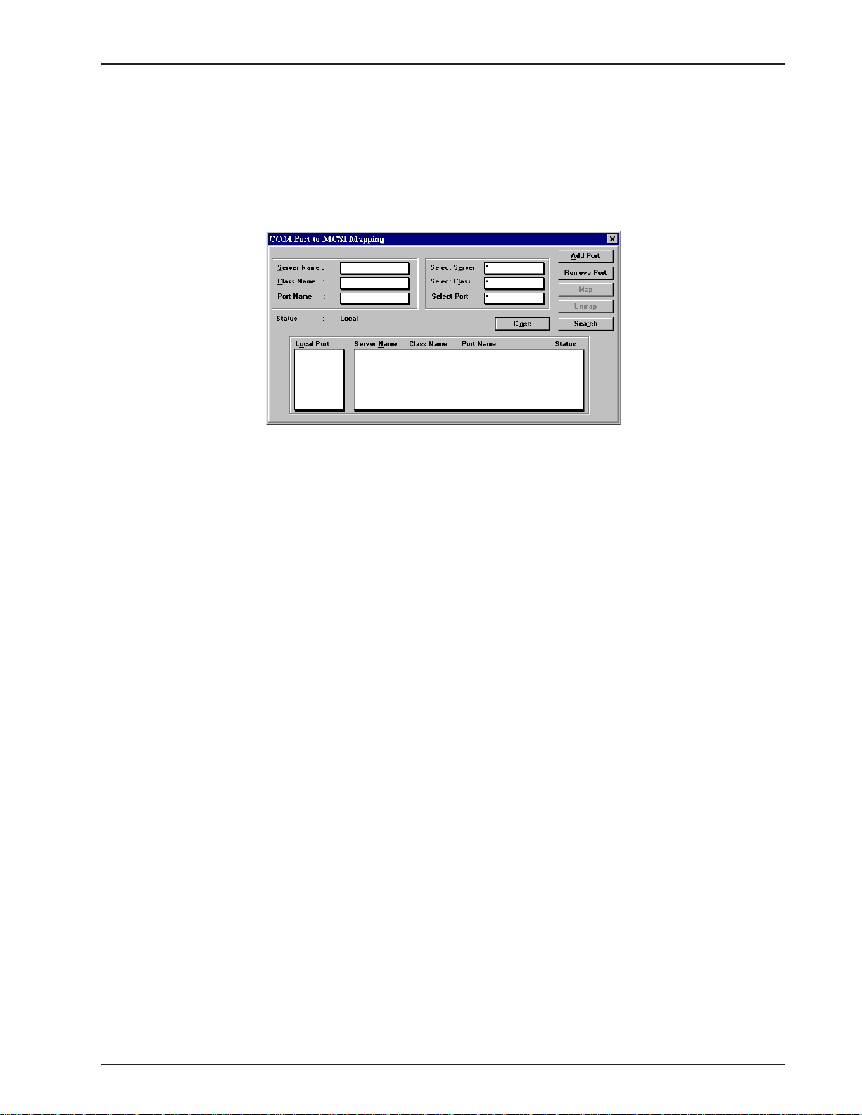
Chapter 6 - RAS Dial-out Redirector
8. The files are loaded onto your system and then the COM Port to MCSI Mapping widow is
displayed.
Note: If the IP option is selected, you will need to make a change to the ROUCON.INI file.
Before making the change, make certain that the RASFinder software has been installed and
is running. From a DOS prompt, change the directory location of the RASFinder 3.10
software and then edit the ROUCON.INI by changing the line” AG Network Interface To Use
= 0” to “AG Network Interface To Use = 1”. Once you’ve done this, save and download the
changes.
Click Add Port to add a port to the Local Port list box.
If you want a specific line, click a COM port in the Local Port list box, then click the line to which
you want to map that particular COM Port. The status message "Mapped to MCSI" should
appear above the Local Port list box.
Click Remove Port to permanently remove a port from the Local Port list box.
Click the Unmap button if you want to unmap a line.
Click the Search button to search for lines on a server.
Click the Close button when finished.
At this time Your WINMCSI software installation is complete. Proceed to the next section,
“Running the WINMCSI Workstation Software.”
RF300E/RF310E 95
Page 96

RASFinder RF300E/RF310E User Guide
Running the WINMCSI Workstation Software
WINMCSI has a workstation portion of the software that LAN users run and use to log onto the
communications server prior to running datacomm software on their client PCs. The following steps
guide you through this process.
1. Start WINMCSI, click Start | Programs | MultiTech MCSI | ComMap.
2. The ComMap for Windows window is displayed.
The buttons from left to right are: Login, Logout, Map, Unmap, and Exit.:
3. To setup ComMap, click Setup.
Click the Network T ype command. The Network Type dialog box is displayed. Y our current
network type is highlighted. You can change the network type by clicking the option button
appropriate for your network. Click OK when finished. You must restart Windows if you change
this setting.
Note: Do not change the network type unless you have changed the network. Also, make sure
that your SYSTEM.INI file contains the device drivers specific to the selected network type.
Click the Connect Timer command. The MCSI Connect Timer dialog box is displayed. The
default value of the connect timer is shown in the Enter Connect Timer Value field. To change the
value of the connect timer, type in a dif ferent value. Click OK when finished.
Click the Baud Change command. The ComMap Baud Change message is displayed. If baud
change by an application is permitted, then this command is checked in the Setup Menu. If baud
change is unchecked in the Setup Menu, then an application cannot change the baud rate (or
other port parameters). Answer the message appropriately.
Click the Default Login command. The Default Login Parameters dialog box is displayed.
Use this dialog box to select a specific RAS to which you want to log into next time Windows is
loaded. Click a RAS from the Available Servers box. If there are no servers in the Available
Servers box, then click the Search button. Type in a User Name and Password (optional) in
their respective fields. Click OK when finished.
ComMap saves these login parameters in your COMMCSI.INI file.
Note: You cannot directly edit the COMMCSI.INI file using a text editor because the password
field is encrypted.
4. If you have not logged into the network, do so now by clicking File | Login, or click the Login
button. The MCSI Login window is displayed.
RF300E/RF310E96
Page 97

Chapter 6 - RAS Dial-out Redirector
The Available Servers box lists the names of the available servers. Click the name of the server
to which you want to attach, type a User Name and Password in their respective fields, and then
click Login. A window is displayed stating that your login was successful. Click OK. If there are
no servers listed in the Available Servers box, then click the Search button to search for a
server.
5. At the ComMap for Windows main window, view your log status by clicking File | Log Status.
The MCSI Login Status window is displayed.
This window shows the name of the server to which you are logged in and the name with which
you logged in. Click Close when you are finished.
6. At the ComMap for Windows main window (to map a COM port through MCSI) click Map | Map.
The COM Port to MCSI Mapping window is displayed.
RF300E/RF310E 97
Page 98

RASFinder RF300E/RF310E User Guide
Note: Windows 98/95 users will have two additional buttons in this box, the Add Port and the
Remove Port buttons. You must click the Add Port button to view Local Ports. Click the
Remove Port button to remove Local Ports.
If you want to get the first available line, click the Map button and then click the Close button and
go to step 7.
If you want a specific line, click a COM Port in the Local Port list box, then click the line to which
you want to map that particular COM Port. The status message "Mapped to MCSI" should
appear above the Local Port list box.
Click Unmap if you want to unmap a line.
Click Search to search for lines on a server .
Click Close when finished.
7. To view a list of mapped COM ports, click Map | Map List, or click the Map button. Click Close
when finished.
8. To unmap a COM port, click Unmap | Unmap, or click the Unmap button. Click the listing you
want to unmap and then click Unmap.
9. To logout from the network, click File | Logout, or click the Logout button.
10. To exit from WINMCSI, click File | Exit, or click the Exit button. Otherwise you may minimize the
screen to minimize WINMCSI to an icon.
RF300E/RF310E98
Page 99

Remote Access Device
Chapter 7 - Remote Configuration and Management
Page 100

RASFinder RF300E/RF310E User Guide
Introduction
This chapter provides procedures for viewing or changing the configuration of a remote unit. T wo
methods are provided to access a remote unit; the first method is modem-based and the second
method uses IP. Within the IP method, three different applications can be used: 1) LAN-Based
configuration using TFTP (Trivial File Transfer Protocol), 2) T elnet as a client application, or 3) a
standard Web browser on the Internet.
Remote Configuration
Remote configuration requires that the RASFinder software be installed on the local PC. The local
PC then controls the remote RASFinder either through the modem connection or over the LAN.
Modem-Based
To remotely configure a RASFinder, a local PC needs to be connected to a dial-up line and the
RASFinder software configured to call the remote RASFinder. The remote RASFinder needs to have
a modem connected to a dial-up line and the Command port. Once the connection to the remote unit
is made, you can change the configuration as required. Once the configuration is changed, you can
download the new configuration to the remote RASFinder. Perform the following steps to remotely
configure a RASFinder through a modem connection.
1. At the remote site, remove the serial cable from the PC to the Command port connector on the
back panel of the RASFinder.
2. At the remote site, connect a special cable (Remote Configuration Cable) from the Command
port connector on the back panel of the RASFinder to the RS-232 connector on the modem. The
special cable is a serial cable with male connectors on both ends. Refer to Appendix A for cable
details.
a. Connect the modem to your local telephone line.
b. Provide your telephone number to the person verifying your configuration.
c. Configure the remote modem for 19200 baud and turn on Force DTR.
3. At the main site, connect your local PC to a modem that is connected to a dial-up line.
4. Install the RASFinder software on the local PC. When installed, click Start | Programs |
RASFinder | Configuration Port Setup, or double-click the Configuration Port icon in the
RASFinder program group.
5. The Port Setup dialog box is displayed.
RF300E/RF310E100
 Loading...