

Page 1
PS9600 Power Supply
User Guide
Page 2

PS9600 Power Supply User Guide
P/N 82064802, Revision C
Copyright © 1997 by Multi-Tech Systems, Inc.
All rights reserved. This publication may not be reproduced, in whole or in part, without prior expressed
written permission from Multi-Tech Systems, Inc.
Multi-Tech Systems, Inc. makes no representation or warranties with respect to the contents hereof and
specifically disclaims any implied warranties of merchantability or fitness for any particular purpose.
Furthermore, Multi-Tech Systems, Inc. reserves the right to revise this publication and to make changes
from time to time in the content hereof without obligation of Multi-Tech Systems, Inc., to notify any
person or organization of such revisions or changes.
Revision Date Description
A
B
C
3/31/97
5/27/97
11/17/97
Manual released.
Manual updated.
Manual updated
Multi-Tech, CommPlete, and the Multi-Tech logo are trademarks of Multi-Tech Systems, Inc. Other
trademarks and trade names mentioned in this publication belong to their respective owners.
Multi-Tech Systems, Inc.
2205 Woodale Drive
Mounds View, Minnesota 55112
(612) 785-3500 or (800) 328-9717
U.S. Fax (612) 785-9874
Technical Support (800) 972-2439
BBS (612) 785-3702 or (800) 392-2432
Fax Back (612) 717-5888
Internet Address: http://www.multitech.com
Page 3

Federal Communications Commission Statement
This equipment has been tested and found to comply with the limits for a Class A digital device, pursuant
to Part 15 of the FCC Rules. These limits are designed to provide reasonable protection against harmful
interference when the equipment is operated in a commercial environment. This equipment generates,
uses, and can radiate radio frequency energy, and if not installed and used in accordance with the instruction manual, may cause harmful interference to radio communications. Operation of this equipment
in a residential area is likely to cause harmful interference, in which case the user will be required to
correct the interference at his own expense.
Warning: Changes or modifications to this unit not expressly approved by the party responsible for
compliance could void the user’s authority to operate the equipment.
CommPlete Communications Server iii
Page 4

iv CommPlete Communications Server
Page 5

v
Table of Contents
1 Introduction .................................................................... 1
Introduction ...................................................................................................................................................... 2
Description ........................................................................................................................................................ 2
Features......................................................................................................................................................... 2
Technical Specifications .................................................................................................................................... 3
Manual Organization......................................................................................................................................... 3
2 Installation ...................................................................... 5
Introduction ...................................................................................................................................................... 6
Pre-Installation Notes ....................................................................................................................................... 6
Installation Procedure....................................................................................................................................... 6
3 Operation ........................................................................ 7
Introduction ...................................................................................................................................................... 8
Power Switch ..................................................................................................................................................... 8
Power Indicator ................................................................................................................................................. 8
4 Solving Problems ........................................................... 9
Introduction .....................................................................................................................................................10
LED Indicators..................................................................................................................................................10
Power Supply LED............................................................................................................................................10
Adjustment of the PS9600 Power Supply.........................................................................................................10
Important Safety Considerations.....................................................................................................................11
Fuse Replacement........................................................................................................................................11
Insertion and Removal of a Power Supply ..................................................................................................12
Safety Disconnect Device .............................................................................................................................12
Index..................................................................................13
CommPlete Communications Server
Page 6

vi CommPlete Communications Server
Page 7

1 Introduction
CommPlete Communications Server 1
Page 8
PS9600 Power Supply User Guide
Introduction
This manual describes the field installation of a Multi-Tech PS9600 power supply into a CommPlete
Communications Server CC9600 chassis. Installation and troubleshooting of the PS9600 should be
performed only by qualified service personnel.
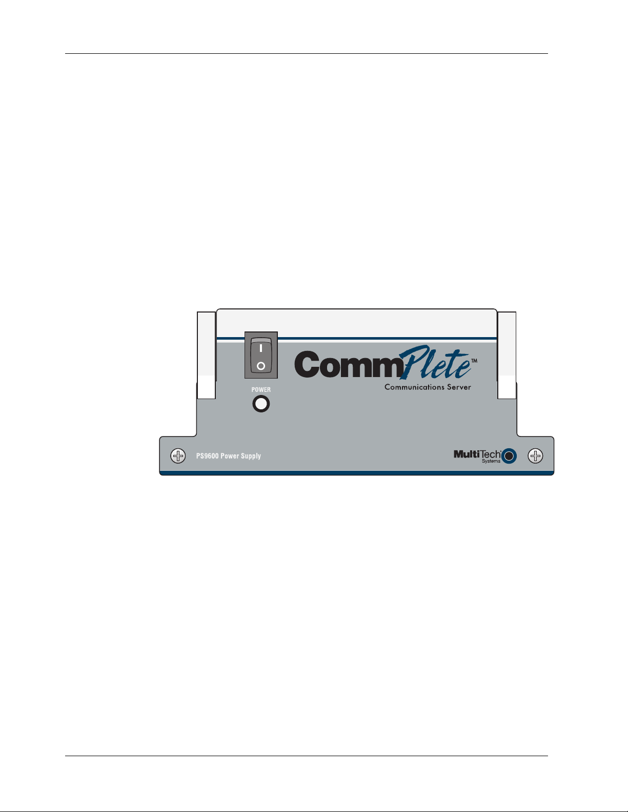
Description
The PS9600 is a universal input switching power supply for the CommPlete Communications Server. Two
PS9600 power supplies are installed as standard equipment in each CommPlete CC9600 chassis. The
outputs of the two power supplies are connected in parallel to the CC9600 chassis power bus. If any of the
outputs on either power supply fails or is too low, the other power supply takes over with no switchover
time, and supplies all the power required to run the system. (This assumes that both power supplies are
turned on.)
Figure 1. PS9600 power supply.
Features
• Dual redundant, universal input switching supply.
• Front panel on/off switch and power LED indicator.
• Power LED lights only if all outputs are good.
• Outputs paralleled for redundancy.
• No switchover time for redundant supply takeover.
• Short circuit protection on all outputs.
• Over-voltage protection on 5 VDC output
• Logic level output signal for “All voltages OK.”
2 CommPlete Communications Server
Page 9

Technical Specifications
Input voltage 100 VAC to 240 VAC RMS
Input frequency 50/60 Hz
Input current 8 A @ 115 V at full load
4 A @ 230 V at full load
1 Introduction
Output voltage at
maximum current
5 V regulation ± 0.1% at full load
5 V OVP 125-132% of output voltage
Dielectric strength,
input to output
Indicator LED for power good indication
Environmental Temperature range: 0°–40° C (32°–104° F)
Dimensions 7.3 cm × 17.1 cm × 29.8 cm (H × W × D)
Weight 2.27 kg (5 lb)
Limited Warranty Two years
Fuses 12 A 250 V fast blow
Manual Organization
Chapter 1 Introduction
This chapter describes the PS9600, gives its technical specifications, and provides a guide to the
organization of the manual.
5 VDC @ 65 A
21 VDC @ 0.5 A
3750 VRMS per EN60950
Humidity range: 0–95% (noncondensing)
2.88 in.× 6.75 in.× 11.75 in. (H × W × D)
Chapter 2 Installation
This chapter describes how to install the PS9600 into the CommPlete chassis
Chapter 3 Operation
This chapter describes briefly how to operate the PS9600 power supply.
Chapter 4 Solving Problems
This chapter describes how to troubleshoot the PS9600 and adjust the output.
CommPlete Communications Server 3
Page 10

Page 11

2 Installation
CommPlete Communications Server 5
Page 12

PS9600 Power Supply User Guide
Introduction
This chapter describes how to install the PS9600 power supply into a CommPlete Communication Server
CC9600 chassis. This equipment should be installed only by a qualified service person.
Pre-Installation Notes
• All installation must be done by a qualified service person.
• Warning: Interconnection directly, or by way of other apparatus, of ports marked “SAFETY
WARNING see instructions for use” with ports marked or not so marked may produce hazardous
conditions on the network. Advice should be obtained from a competent engineer before such a
connection is made.
• Warning: Ports that are connected to other apparatus are defined as SELV. To ensure conformity to
EN 41003, ensure that these ports are only connected to the same type on the other apparatus.
• To reduce emissions, be sure to use blanking plates to cover empty slots in the CC9600 chassis.
Installation Procedure
1. Unpack the PS9600 assembly from its packaging and save the packaging for possible future use.
Perform a visual inspection of the PS9600. If you are concerned about its condition, call Technical
Support for instructions.
2. Make sure the PS9600 power switch is in the off (O) position.
3. Remove the cover plate on the CC9600 if necessary. The PS9600 is hot-swappable.
4. Holding the PS9600 by the front panel and bottom corners, place the PS9600 into the open power
supply slot. Make sure that the top rails on the PS9600 mate properly with the plastic guides in the
CC9600.
5. Slowly slide the PS9600 into the CC9600 chassis until you feel the PS9600’s connectors mate with the
CC9600’s connectors.
6. Tighten the PS9600’s retaining screws.
7. Turn the PS9600 power switch on to the on (I) position.
8. Observe the PS9600 “outputs good” LED. If it is not lit, see Chapter 4. If it is lit, proceed with normal
CommPlete Communications Server operation.
9. After you turn on the power supplies, you should check the 5 Voutput. See page 10 for details. The
supplies can be re-checked as part of your regular system maintenance.
6 CommPlete Communications Server
Page 13

3 Operation
CommPlete Communications Server 7
Page 14

PS9600 Power Supply User Guide
Introduction
This chapter provides information about operating your PS9600 Power Supply after it is installed.
Power Switch
The PS9600 has a power switch on the front panel that is labeled with the international I (on) and O (off)
symbols. For the most reliable operation, both power supplies should be turned on whenever the
CommPlete Communications Server is operating.
Power Indicator
The power indicator lights if all outputs are good. If any one of the outputs on the power supply goes bad,
this indicator goes out. If a power supply fails and the redundant power supply is installed and turned on,
the good power supply takes over with no switchover time.
8 CommPlete Communications Server
Page 15

4 Solving Problems
CommPlete Communications Server 9
Page 16

PS9600 Power Supply User Guide
Introduction
This chapter provides information needed to identify and fix problems with the PS9600 power supply
module. Problems can be observed on the CommPlete system’s front panel LEDs, the control PC’s screen,
or via audio alarm or alarm report. In addition, problems can be found when performing the Diagnostic
Tests documented elsewhere in the CommPlete Communications Server
LED Indicators
The CommPlete Communication Server’s front panels contains the following indicators.
• MR9600 controller LEDs.
• Modem card LEDs. The number of LEDs on your modem card may vary, depending on the type of
modem card in your chassis. Please refer to your modem’s user guide for LED descriptions.
• PS9600 power supply LED.
The PS9600 power supply LED is described below. Each of the other LED indicators is described in the
applicable manual.
User Guide
.
Power Supply LED
This LED goes out if one of the PS9600 power supply outputs goes low or fails altogether. In normal
operation it is lit. The recovery procedure to be used depends on whether the CommPlete chassis has one
or two PS9600 power supplies installed.
Indication: LED is on (either one or two PS9600s installed).
Meaning: The power supply (or supplies) are operating properly.
Recovery: No action required.
Indication: LED is off (one PS9600 installed).
Meaning: At least one of the outputs is low or out.
Recovery: Turn off the power supply, remove it, and check the fuse. Replace the fuse if it is blown;
call Technical Support if the fuse is good (Chapter 5).
Indication: LED is off (two PS9600s are installed).
Meaning: At least one of the outputs is low or out. Power is being supplied by the second PS9600.
Recovery: Turn off the PS9600 that has the LED off, and remove the PS9600. Replace the fuse if it is
blown; call Technical Support if the fuse is good (Chapter 5).
Adjustment of the PS9600 Power Supply
For optimal operation of the CommPlete Communications Server, the 5 V output of the PS9600 power
supply should be adjusted to 5.1 VDC. The 5-volt test points are located on the back of the chassis between
the power supply fans.
10 CommPlete Communications Server
Page 17

4 Solving Problems
A
y)
A
Procedure
1. Turn off the power supply that is not being adjusted.
2. Place your voltmeter’s probes on the test points.
3. Two trimpots, one for each power supply, are located on the back of the chassis between the power
supply fans. Adjust the 5 volt trimpot that is closest to the power supply that you are testing to 5.1
VDC by turning it clockwise to increase the voltage, or counterclockwise to decrease the voltage.
4. Check the measurement.
5. Repeat the above steps, as necessary, until the voltage is correct.
6. Repeat for the second PS9600 supply with the first PS9600 power supply turned off.
0 V test point (SELV)
5 V adjust (right power suppl
C power (right power supply)
MONITOR
T1IN OUT
CONFIG PORT ALARM
VIDEO
KEYBOARD
MONITOR
T1IN OUT
CONFIG PORT ALARM
VIDEO
KEYBOARD
5 V test point (SELV)
5 V adjust (left power supply)
C power (left power supply)
T1IN OUT
MONITOR
CONFIG PORT ALARM
VIDEO
KEYBOARD
MONITOR
T1IN OUT
CONFIG PORT ALARM
VIDEO
KEYBOARD
Figure 2. Power supply connectors and test points
Important Safety Considerations
Fuse Replacement
There is one replaceable fuse in the PS9600 power supply. Qualified service personnel may replace the fuse
with one of the same type and rating as indicated on the PS9600 Fuse Label.
CommPlete Communications Server 11
Page 18

PS9600 Power Supply User Guide
Insertion and Removal of a Power Supply
Qualified service personnel may insert or remove a power supply without turning off the system. We
recommend that you insert the power supply slowly. If the power supply is not replaced, a cover plate
must be installed.
Safety Disconnect Device
The switches on the power supplies are not safety disconnect devices. To reduce the risk of electric shock,
unplug the two input power cords from the back of the CC9600.
Install the power outlet near the CC9600, and place the equipment so that the outlet is easily accessible.
12 CommPlete Communications Server
Page 19

Index
adjusting the output, 11
BBS, Multi-Tech, 16
CC9600 chassis, 6
CompuServe, 17
description, 2
dimensions of PS9600, 3
fax-back service, 18
features, 2
fuse, 3, 10
installation, 6
Internet, 2, 18
—A—
—B—
—C—
—D—
—F—
—I—
—L—
—M—
manual organization, 3
Multi-Tech BBS, 16
—O—
operating the PS9600, 8
—P—
power bus, 2
power cords, 12
power indicator, 6, 8, 10
power switch, 8
—S—
safety, 6, 12
service, 14
solving problems, 10
specifications, 3
switchover time, 2, 8
—T—
technical specifications, 3
technical support, 15, 17
test points, 11
troubleshooting, 10
LED, 10
warranty, 14
World Wide Web, 18
CommPlete Communications Server 13
—W—
Page 20

PS9600 Power Supply User Guide
14 CommPlete Communications Server
Page 21

 Loading...