

Page 1

TM
MultiVOIP FX
SIP Gateways
Models: MVPFX2-2
User Guide for Voice/IP Gateways
MVPFX2-4
MVPFX2-8
Page 2

User Guide
S000411A
MultiVOIP FX Analog SIP Gateways
This publication may not be reproduced, in whole or in part, without prior expressed written permission from Multi-Tech Systems,
Inc. All rights reserved.
Copyright © 2006, by Multi-Tech Systems, Inc.
Multi-Tech Systems, Inc. makes no representations or warranties with respect to the contents hereof and specifically disclaims any
implied warranties of merchantability or fitness for any particular purpose. Furthermore, Multi-Tech Systems, Inc. reserves the right
to revise this publication and to make changes from time to time in the content hereof without obligation of Multi-Tech Systems, Inc.
to notify any person or organization of such revisions or changes.
Record of Revisions
Revision Description
A 06/29/06. Initial release. Describes 13.01 software release.
Patents
This Product is covered by one or more of the following U.S. Patent Numbers: 6151333, 5757801, 5682386, 5.301.274; 5.309.562;
5.355.365; 5.355.653; 5.452.289; 5.453.986. Other Patents Pending.
Trademark
Trademark of Multi-Tech Systems, Inc. is the Multi-Tech logo. Windows is a registered trademarks of Microsoft.
GENERAL CONTACT
Multi-Tech
Systems, Inc.
2205 Woodale Drive
Mounds View,
Minnesota
55112, USA
(763) 785-3500
(800) 328-9717
Fax: 763-785-9874
www.multitech.com
TECHNICAL SUPPORT
Country By E-mail By Phone
U.S. & Canada tsupport@multitech.com (800) 972-2439
France support@multitech.fr (33) 1-64 61 09 81
India support@multitechindia.com (91) 124-340778
U.K. support@multitech.co.uk (44) 118 959 7774
Rest of World support@multitech.com (763) 785-3500
(Models MVPFX2-2, MVPFX2-4 & MVPFX2-8)
2
Page 3

CONTENTS
CHAPTER 1: OVERVIEW ......................................................................................................................................................5
ABOUT THIS MANUAL..............................................................................................................................................................6
INTRODUCTION TO ANALOG MULTIVOIP FX SIP GATEWAY VOICE-OVER-IP UNITS (MVPFX2-2/4/8) ................................7
MultiVOIP Front Panel LEDs...........................................................................................................................................10
COMPUTER REQUIREMENTS ...................................................................................................................................................12
SPECIFICATIONS .....................................................................................................................................................................12
INSTALLATION AT A GLANCE .................................................................................................................................................13
RELATED DOCUMENTATION...................................................................................................................................................13
CHAPTER 2: QUICK START GUIDE.................................................................................................................................14
MULTIVOIP STARTUP TASKS ................................................................................................................................................15
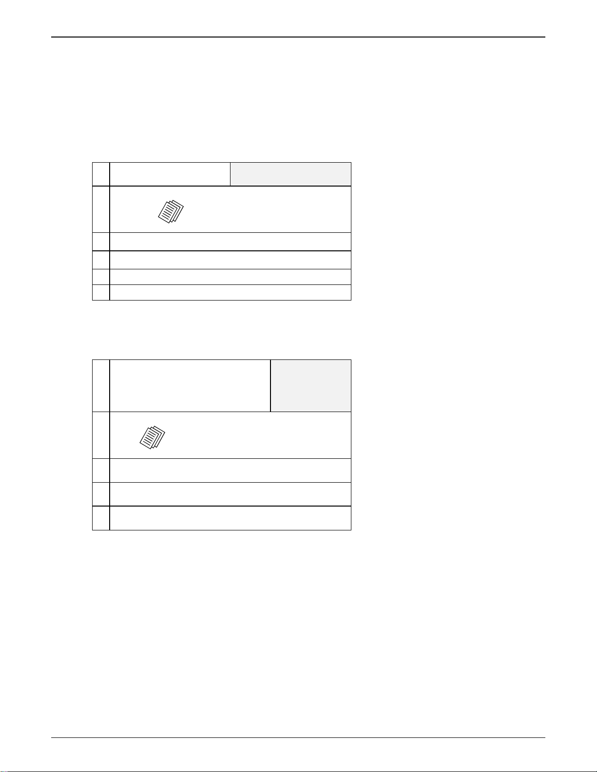
Phone/IP Details *Absolutely Needed* Before Starting the Installation...........................................................................16
Gather IP Information........................................................................................................................................................................16
Gather Telephone Information (Analog)........................................................................................................................................... 16
Config Info CheckList.......................................................................................................... ............................................................. 17
Identify Remote VOIP Site to Call.................................................................................................................................................... 17
Command/Control Computer Setup (Specs & Settings) ....................................................................................................18
Placement ..........................................................................................................................................................................18
Quick Hookup for MVPFX2-4 & MVPFX2-8....................................................................................................................19
Quick Hookup for MVPFX2-2...........................................................................................................................................20
Ensure that Java & Browser Versions will Support Web-Ba sed GUI...............................................................................21
Changing the IP Address through the Console Connection..............................................................................................21
Phone/IP Starter Configuration.........................................................................................................................................28
Phonebook Starter Configuration (with remote voip)........................................................................................................29
Outbound Phonebook........................................................................................................................................................................29
Inbound Phonebook........................................................................................................................................................................... 32
Phonebook Tips .................................................................................................................................................................34
Phonebook Example ..........................................................................................................................................................36
Connectivity Test ...............................................................................................................................................................41
Troubleshooting.................................................................................................................................................................43
CHAPTER 3: MECHANICAL INSTALLATION AND CABLI NG..................................................................................44
INTRODUCTION.......................................................................................................................................................................45
SAFETY WARNINGS ................................................................................................................................................................45
General Safety ...................................................................................................................................................................45
Lithium Battery Caution ....................................................................................................................................................45
Ethernet (WAN) Ports Caution..........................................................................................................................................45
Safety Warnings Telecom...................................................................................................................................................46
UNPACKING YOUR MULTIVOIP.............................................................................................................................................47
Unpacking the MVPFX2-4/8..............................................................................................................................................47
Unpacking the MVPFX2-2.................................................................................................................................................48
Safety Recommendations for Rack Installations of MVPFX2-4 or MVPFX2-8.................................................................50
19-Inch Rack Enclosure Mounting Procedure...................................................................................................................51
CABLING PROCEDURE FOR MVPFX2-4/8...............................................................................................................................52
Cabling Procedure for MVPFX2-2....................................................................................................................................53
CHAPTER 4: MULTIVOIP & AUXILIARY SOFTWARE...............................................................................................55
INTRODUCTION.......................................................................................................................................................................56
SUMMARY ..............................................................................................................................................................................56
CHAPTER 5: TECHNICAL CONFIGURATION...............................................................................................................57
CONFIGURING THE MULTIVOIP.............................................................................................................................................58
CONFIGURATION BY WEB GUI...............................................................................................................................................59
Pre-Requisites....................................................................................................................................................................59
IP Parameters.....................................................................................................................................................................................59
Telephony Interface Parameters........................................................................................................................................................ 60
Config Info CheckList.......................................................................................................... ............................................................. 60
3
Page 4

Contents MultiVOIP User Guide
Procedure for Configuration by Web GUI (Summary)......................................................................................................61
Local Configuration Procedure (Detailed)........................................................................................................................61
CHAPTER 6: PHONEBOOK CONFIGURATION...........................................................................................................101
CONFIGURING MULTIVOIP PHONEBOOKS ...........................................................................................................................102
PHONEBOOK EXAMPLES .......................................................................................................................................................113
2 Site Example .................................................................................................................................................................113
Configuring Mixed Digital/Analog VOIP Systems ..........................................................................................................119
Call Completion Summaries............................................................................................................................................124
Variations in PBX Characteristics...................................................................................................................................127
CHAPTER 7: OPERATION AND MAINTENANCE.......................................................................................................128
OPERATION AND MAINTENANCE SUMMARY ........................................................................................................................129
System Information screen...............................................................................................................................................130
Statistics Screens .............................................................................................................................................................133
About Call Progress.........................................................................................................................................................133
About IP Statistics............................................................................................................................................................138
GENERAL OPERATION FUNCTIONS .......................................................................................................................................142
Change Username/Password...........................................................................................................................................142
Establishing a Username and Password........................................................................................................................................... 142
About Passwords & Login/Logout from Specific Computers.........................................................................................................143
Logout..............................................................................................................................................................................144
Save & Apply...................................................................................................................................................................144
Reboot Voip .....................................................................................................................................................................145
Restore Factory Defaults.................................................................................................................................................145
UPGRADING MULTIVOIP FIRMWARE...................................................................................................................................146
Introduction .....................................................................................................................................................................146
Identifying Current Firmware Version............................................................................................................................146
Obtaining Updated Firmware..........................................................................................................................................147
UPGRADING MULTIVOIP FIRMWARE VIA FTP CLIENT AND VOIP’S BUILT-IN FTP SERVER FUNCTION...............................149
SYSLOG SERVER FUNCTIONS ...............................................................................................................................................171
CHAPTER 8 WARRANTY, SERVICE, AND TECH SUPPORT....................................................................................174
LIMITED WARRANTY............................................................................................................................................................175
REPAIR PROCEDURES FOR U.S. AND CANADIAN CUSTOMERS ..............................................................................................175
TECHNICAL SUPPORT ...........................................................................................................................................................176
Contacting Technical Support.........................................................................................................................................176
CHAPTER 9: REGULATORY INFORMATION.............................................................................................................177
EMC, Safety, and R&TTE Directive Compliance............................................................................................................178
FCC DECLARATION..............................................................................................................................................................178
Industry Canada ..............................................................................................................................................................178
FCC Part 68 Telecom......................................................................................................................................................178
Canadian Limitations Notice...........................................................................................................................................179
WEEE Statement..............................................................................................................................................................180
APPENDIX A: CABLE PINOUTS.....................................................................................................................................181
APPENDIX A: CABLE PINOUTS.............................................................................................................................................182
Command Cable ..............................................................................................................................................................182
Ethernet Connector..........................................................................................................................................................182
APPENDIX B: TCP/UDP PORT ASSIGNMENTS...........................................................................................................183
WELL KNOWN PORT NUMBERS............................................................................................................................................184
PORT NUMBER ASSIGNMENT LIST........................................................................................................................................184
INDEX....................................................................................................................................................................................185
4
Page 5

Chapter 1: Overview
5
Page 6
Overview MultiVOIP User Guide
About This Manual
This manual is about Voice-over-IP products made by Multi-Tech Systems, Inc. It describes three analog
MultiVOIP
TM
FX units that operate with the SIP transmission protocol only, namely, models MVPFX2-2,
MVPFX2-4, and MVPFX2-8.
These MultiVOIP units can inter-operate with other contemporary analog MultiVOIP units (MVP130,
MVP130FXS, MVP210, MVP410, and MVP810), with contemporary SIP-Surivability MultiVOIP units
(MVP210-SS, MVP410-SS, and MVP810-SS), with contemporary BRI MultiVOIP units (MVP410ST &
MVP810ST), with contemporary digital T1/E1/ISDN-PRI MultiVOIP units (MVP2410 and MVP3010), and
with the earlier generation of MultiVOIP products (MVP200, MVP400, MVP800, MVP120, etc.)
The table below describes the vital characteristics of the various models described in this manual.
Analog MultiVOIP SIP-Only Gateways
Description
Model
Function analog voip gateway, SIP only,
MVPFX2-8 MVPFX2-4 MVPFX2-2
analog voip gateway, SIP only,
web GUI only (no Windows
GUI)
web GUI only (no Windows
GUI)
Capacity 8 channels 4 channels 2 channels
Chassis/
19” 1U rack mount 19” 1U rack mount table-top unit
Mounting
How to Use This Manual. In short, use the index and the examples.
When our readers crack open this large manual, they generally need one of two things: information on a
very specific software setting or technical parameter (about telephony or IP) or they need help when setting
up phonebooks for their voip systems. The index gives quick access to voip settings and parameters. It’s
detailed. Use it. The best way to learn about phonebooks is to wade through examples like those in our
Phonebook Configuration chapter. Finally, this manual is meant to be comprehensive. If you notice that
something important is lacking, please let us know.
analog voip gateway, SIP only,
web GUI only (no Windows
GUI)
Additional Resources. The MultiTech web site (www.multitech.com) offers both a list of Frequently Asked
Questions (the MultiVOIP FAQ) and a collection of resolutions of issues that MultiVOIP users have
encountered (these are Troubleshooting Resolutions in the searchable Knowledge Base).
6
Page 7
MultiVOIP FX User Guide Overview
Introduction to Analog MultiVOIP FX
SIP Gateway Voice-over-IP Units
(MVPFX2-2/4/8)
VOIP: The Free Ride. We proudly present Multi-Tech's MVPFX2-2/4/8 MultiVOIPTM FX SIP Gateways.
These three models allow voice/fax communication to be transmitted at no additional expense over your
existing IP network, which has ordinarily been data only. To access this free voice and fax communication,
you simply connect the MultiVOIP to your telephone equipment and your existing Internet connection.
These analog MultiVOIPs inter-operate readily with T1 or E1 MultiVOIP units.
WAN
SPD
COL
12345678
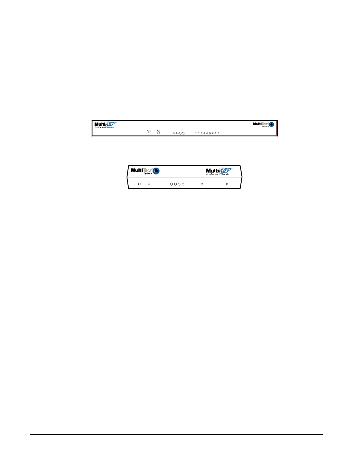
Figure 1-1: MVPFX2-8 Chassis
Power
Boot
LNK
FDX SPD COL
Voice/Fax 1 Voice/Fax 2Ethe rnet
Figure 1-2: MVPFX2-2 Chassis
Capacity. The MultiVOIP FX model MVPFX2-8 is an eight-channel unit, the model MVPFX2-4 is a fourchannel unit, and the MVPFX2-2 is a two-channel unit. All three of these MultiVOIP units have a
10/100Mbps Ethernet interface for its full-featured web-based configuration GUI and a console port for
local access to basic startup configuration parameters (like the gateway’s IP address and password).
Mounting. Mechanically, the MVPFX2-4 and MVPFX2-8 MultiVOIP FX units are designed for a one-high
industry-standard EIA 19-inch rack enclosure. The product must be installed by qualified service
personnel in a restricted-access area, in accordance with Articles 110-16, 10-17, and 110-18 of the National
Electrical Code, ANSI/NFPA 70. The MVPFX2-2 is a table-top unit.
7
Page 8
Overview MultiVOIP User Guide
Phone System Transparency. These MultiVOIPs inter-operate with a telephone switch or PBX, acting as a
switching device that directs voice and fax calls over an IP network. The MultiVOIPs have “phonebooks,”
directories that determine to who calls may be made and the sequences that must be used to complete calls
through the MultiVOIP. The phonebooks allow the phone user to interact with the VOIP system just as
they would with an ordinary PBX or telco switch. When the phonebooks are set, special dialing sequences
are minimized or eliminated altogether. Once the call destination is determined, the phonebook settings
determine whether the destination VOIP unit must strip off or add dialing digits to make the call appear at
its destination to be a local call.
Voip Protocol. The MVPFX units use the SIP protocol only. (“SIP” means Session Initiation Protocol.)
Data Compression & Quality of Service. The analog MultiVOIP
TM
FX unit comes equipped with a variety
of data compression capabilities, including G.723, G.729, and G.711 and features DiffServ quality-of-service
(QoS) capabilities.
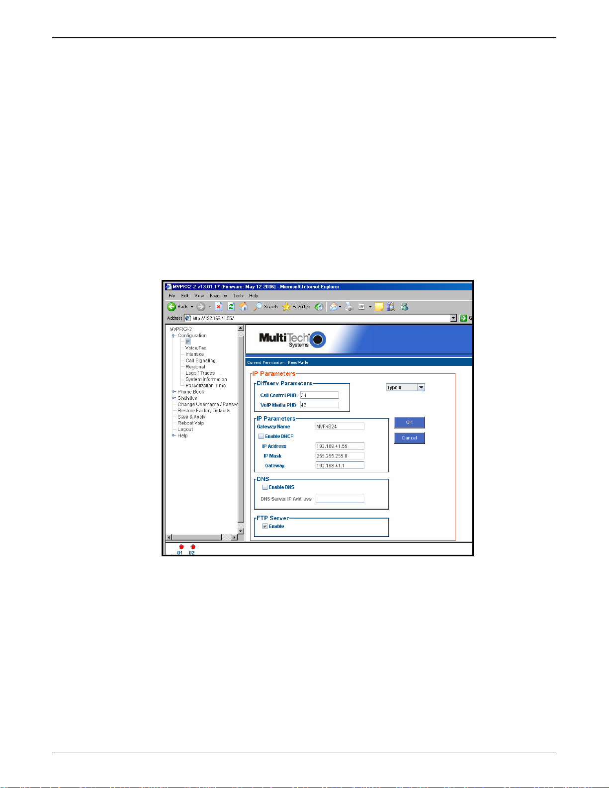
Management. Configuration and system management for the MVPFX2 units is done primarily through a
web interface. Once you know the IP address of an MVPFX2 unit, you can contact that unit with a web
browser and set the unit’s operating parameters, which are grouped into several separate screens.
Figure 1-3: The Presentation of the MultiVOIP Web-Based GUI (IP Parameters screen shown)
Certain base-level parameters (like the IP address and password of the unit) can be set by connecting the
MVPFX2 unit’s “Console” receptacle to a serial connector on a PC (using a DB9-to-RJ45 connector).
The primary advantage of the web GUI is remote access for control and configuration. The controller PC
and the MultiVOIP unit itself must both be connected to the same IP network and their IP addresses must
be known.
8
Page 9
MultiVOIP FX User Guide Overview
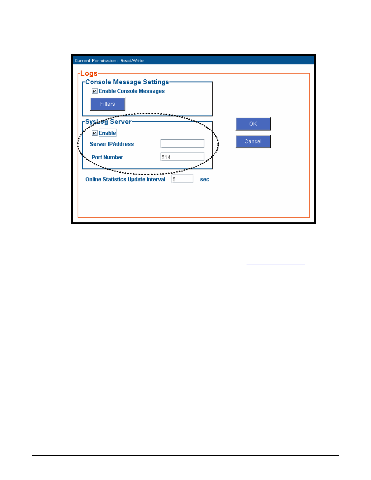
Logging of System Events. MultiTech has built SysLog Server functionality into the software of the
MultiVOIP units. SysLog is a de facto standard for logging events in network communication systems.
Figure 1-4: Logging with SysLog
The SysLog Server resides in the MultiVOIP unit itself. To implement this functionality, you will need a
SysLog client program (sometimes referred to as a “daemon”). SysLog client programs, both paid and
freeware, can be obtained from Kiwi Enterprises, among other firms. See www.kiwisyslog.com
. SysLog
client programs essentially give you a means of structuring console messages for convenience and ease of
use.
MultiTech Systems does not endorse any particular SysLog client program. SysLog client programs by any
qualified provider should suffice for use with MultiVOIP units. Kiwi’s brief description of their SysLog
program indicates the typical scope of such programs. “Kiwi Syslog Daemon is a freeware Syslog Daemon
for the Windows platform. It receives, logs, displays and forwards Syslog messages from hosts such as
routers, switches, Unix hosts and any other syslog enabled device. There are many customizable options
available.”
9
Page 10

Overview MultiVOIP User Guide
MultiVOIP Front Panel LEDs
LED Types. The MultiVOIPs have two types of LEDs on their front panels:
(1) general operation LED indicators (for power, booting, and
ethernet functions), and
(2) channel operation LED indicators that describe the data traffic and performance in each VOIP data
channel.
Active LEDs. On both the MVPFX2-4 and MVPFX2-8, there four WAN LEDs and eight channel-operation
LEDs. However, on the MVPFX2-4, only the left four sets of channel-operation LEDs are functional. On the
MVPFX2-8, all eight sets are functional.
WAN
SPD
COL
12345678
Figure 1-5. MVPFX2-8 LEDs
Similarly, the MVPFX2-2 has four WAN/Ethernet general-operation indicator LEDs and two channeloperation LEDs, one for each channel.
Voice/Fax 1 Voice/Fax 2Et hernet
Power
Boot
LNK
FDX SPD COL
Figure 1-6. MVPFX2-2 LEDs
10
Page 11

MultiVOIP FX User Guide Overview
LED Descriptions for MultiVOIP-FX2 Units
Front Panel LED Definitions
LED NAME DESCRIPTION
General Operation LEDs (one set on each MultiVOIP model)
Power Indicates presence of power.
Boot
Ethernet
After power up, the Boot LED will be on briefly while the
MultiVOIP is booting. It lights whenever the MultiVOIP is
booting or downloading a setup configuration data set.
FDX. LED indicates whether Ethernet connection is
half-duplex or full-duplex (FDX) and, in half-duplex
mode, indicates occurrence of data collisions. LED is
on constantly for full-duplex mode; LED is off
constantly for half-duplex mode. When operating in
half-duplex mode, the LED will flash during data
collisions.
LNK. Link/Activity LED. This LED is lit if Ethernet
connection has been made. It is off when the link is
down (i.e., when no Ethernet connection exists).
While link is up, this LED will flash off to indicate data
activity.
SPD. Data speed indicator. When lit, data rate is
100 Mbps. When not lit, data rate is 10 Mbps.
COL. Collision indicator. Lit when data
collision is detected on Ethernet network.
Channel-Operation LEDs
Voice/Fax 1
Voice/Fax 2
1, 2, 3, ... 8
On MVPFX2-2 only. This indicator is lit when there is
call activity on Channel 1. If the voip channel is
operating as FXS, the LED is ON when the device
attached to the channel is off hook. If the voip channel
is operating as FXO, the LED is ON when the voip has
seized the line.
On MVPFX2-2 only. This indicator is lit when there is
call activity on Channel 2. If the voip channel is
operating as FXS, the LED is ON when the device
attached to the channel is off hook. If the voip channel
is operating as FXO, the LED is ON when the voip has
seized the line.
On MVPFX2-4 and MVPFX2-8. There is one LED for
each voip channel. The indicator for any channel is lit
when there is call activity on that voip channel. If the
voip channel is operating as FXS, the LED is ON when
the device attached to the channel is off hook. If the
voip channel is operating as FXO, the LED is ON
when the voip has seized the line.
11
Page 12

Overview MultiVOIP User Guide
Computer Requirements
The command computer used in conjunction with the MultiVOIP must meet these requirements:
(a) any reasonably modern PC,
(b) must have an up-to-date version of Java installed (v. 1.5 or higher),
(c) must have an up-to-date web browser installed (at this writing, up-to-date browsers would include
Internet Explorer 6.0(+), Netscape 6.0(+), or Mozilla FireFox 1.0(+).),
(d) must have IP access to the MultiVOIP, and
(e) optionally, have an available serial COM port for a console connection to the MultiVOIP.
This PC will generally be in contact with the MVPFX2 unit via the web. The Console connection, which
requires a cable directly between the PC and the MultiVOIP is, essentially, a backup method of connecting
to the voip. This direct connection can be used to reset the MultiVOIP’s IP address and to upgrade
firmware. The direct connection is not involved in the general operation of the MultiVOIP unit.
Specifications
Parameter
Operating
Voltage/
Current
Mains
Frequencies
Power
Consumption
Mechanical
Dimensions
Weight 7.1 lbs.
Operating
Temperature
Storage
Temperature
/Model
MVPFX2-4
100-240 VAC,
1.2 - 0.6 A
50/60 Hz 50/60 Hz 50/60 Hz
16 watts 26 watts 10 watts
1.75” H x
17.4” W x
8.5” D
4.5cm H x
44.2 cm W x
21.6 cm D
(3.2 kg)
includes power
supply
0° to +60°C (32°
to +120°F);
humidity range
20-90% (noncondensing)
-10°C to +85°C -10°C to +85°C -10°C to +85°C
MVPFX2-8 MVPFX2-2
100-240 VAC
1.2 - 0.6 A
1.75” H x
17.4” W x
8.5” D
4.5cm H x
44.2 cm W x
21.6 cm D
7.24 lbs.
(3.5 kg)
includes power
supply
0° to +60°C (32° to
+120°F); humidity
range 20-90%
(non-condensing)
9 VDC, 1 A,
External power
supply
6.2” W x
9” D x
1.4” H
15.8cm W x
22.9cm D x
3.6cm H
1.8lbs (.82kg)
2.6lbs (1.17kg)
without supply
0° to +60°C (32° to
+120°F); humidity
range 20-90%
(non-condensing)
12
Page 13

MultiVOIP FX User Guide Overview
Installation at a Glance
The basic steps of installing your MultiVOIP network involve unpacking the units, connecting the cables,
and configuring the units using the MultiVOIP web-based graphic user interface (GUI), and confirming
connectivity with another voip site. This process results in a fully functional Voice-Over-IP network.
Related Documentation
The MultiVOIP User Guide (the document you are now reading) comes in electronic form and is included
on your system CD. It presents in-depth information on the features and functionality of Multi-Tech’s
MultiVOIP Product Family. The MultiVOIP Cabling Guide, a printed document, is shipped with each
MVPFX2 unit.
The CD media is produced using Adobe Acrobat
print your copy of a user guide, load Acrobat Reader
the MultiVOIP CD and is also a free download from Adobe’s Web Site:
TM
for viewing and printing the user guide. To view or
TM
on your system. The Acrobat Reader is included on
www.adobe.com/prodindex/acrobat/readstep.html
This MultiVOIP User Guide is also available on Multi-Tech’s Web site at:
http://www.multitech.com
Viewing and printing a user guide from the Web also requires that you have the Acrobat Reader loaded on
your sys tem. To select the MultiVOIP User Guide from the Multi-Tech Systems home page, click Documents and then click
MultiVOIP Family in the product list drop-down window. All documents for this MultiVOIP Product Family will be
displayed. You can then choose User Guide (MultiVOIP Product Family) to view or download the .pdf file.
Entries (organized by model number) in the “knowledge base” and ‘troubleshooting resolutions’ sections of
the MultiTech web site (found under “Support”) constitute another source of help for problems
encountered in the field.
13
Page 14

Chapter 2: Quick Start Guide
14
Page 15

MultiVOIP FX Quick Start Guide Preliminaries & Info Gathering
This chapter contains streamlined instructions to get the MultiVOIP up and running quickly. These startup instructions include assistance on setting up the MultiVOIP’s Inbound and Outbound Phonebooks.
These sections of the Quick Start Guide may be particularly useful for phonebook configuration:
Phonebook Starter Configuration
Phonebook Tips
Phonebook Example (One Common Situation)
The Quick Start Guide also contains a “Phonebook Worksheet” section. You may want to print out several
worksheet copies. Paper copies can be very helpful in comparing phonebooks at multiple sites at a glance.
This will assist you in making the phonebooks clear and consistent and will reduce ‘surfing’ between
screens on the configuration program.
A printed Cabling Guide is shipped with the MultiVOIP and an electronic copy is included on the Product
CD.
MultiVOIP Startup Tasks
Task Summary
Collecting Phone/IP
Details ( vital! )
Command/Control
Computer Setup:
The MultiVOIP must be configured to interface with
your particular phone system and IP network. To do so,
certain details must be known about those phone and IP
systems.
Some modest minimum specifications must be met. A
COM port must be set up.
Specs & Settings
Placement
Decide where you’ll mount the voip.
Hookup Connect power, phone, and data cables per the Quick
Hookup diagrams in this chapter.
Software Installation Check that an up-to-date version of Java (version 1.5) is
on your computer. If not, install it from the MultiVOIP
CD or the Java website.
Phone/IP Starter
Configuration
Phonebook Starter
Configuration
You will enter phone numbers and IP addresses. You’ll
use default parameter values where possible to get the
system running quickly.
Use “Config Info CheckList” (page 17).
The phonebook is where you specify how calls will be
routed. To get the system running quickly, you’ll make
phonebooks for just two voip sites.
Connectivity Test You’ll find out if your voip system can carry phone calls
between two sites. That means you’re up and running!
Troubleshooting Detect and remedy any problems that might have
prevented connectivity.
15
Page 16
Preliminaries & Info Gathering MultiVOIP FX Quick Start Guide
Phone/IP Details *Absolutely Needed*
Before Starting the Installation
The MultiVOIP will interface with both the IP network and the phone system. You must gather
information about the IP network and about the phone system so that the MultiVOIP can be configured to
operate with them properly. A summary of this configuration information appears on page 17 (“Config
Info CheckList”).
Gather IP Information
Ask your computer network
administrator.
#
• IP Address
• IP Mask
• Gateway
• Domain Name Server (DNS) Info (optional)
IP Network Parameters:
Record for each VOIP Site
in System
Info needed to operate:
all MultiVOIP models.
Phone/IP Details *Absolutely Needed*
Gather Telephone Information (Analog)
Analog Phone Parameters
Ask phone company or
telecom manager.
#
• Which interface type is used?
FXS_____ FXO_____
• If FXS, determine whether the line will be used for a
phone, fax, or KTS (key telephone system)
• If FXO, determine if line will be an analog PBX
extension or an analog line from a telco central office
Analog Telephony Interface Parameters:
Record for this VOIP Site
Needed for:
MVPFX2-8
MVPFX2-4
MVPFX2-2
16
Page 17
MultiVOIP FX Quick Start Guide Preliminaries & Info Gathering
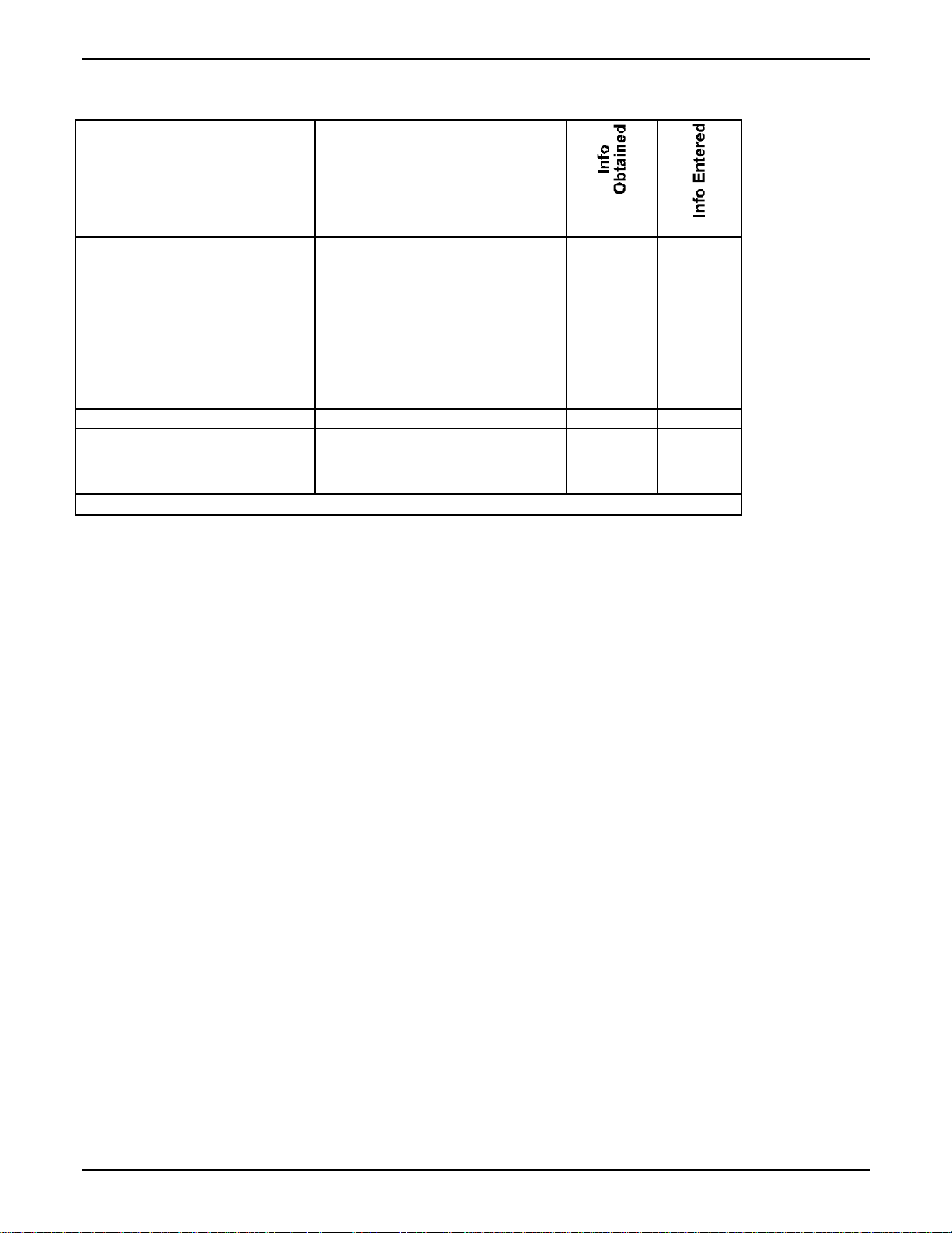
Config Info CheckList
Type of Config Info
Gathered
MultiVOIP
Configuration screen
on which to enter Config
√
Info
IP info for voip unit
● IP address
● Gateway
● DNS IP (if used)
Interface Type
(Choices: FXS or FXO*)
Country Code Regional Parameters
Network Locations of SIP Proxy
units, if used
(IP Address or Domain Name)
Reminder: Be sure to Save & Apply after entering configuration values.
IP Parameters
Interface Parameters
*In FXO/FXS systems, channels used
for phone, fax, or key system are
FXS; channels used for analog PBX
extensions or analog telco lines are
FXO.
SIP Call Signaling
Identify Remote VOIP Site to Call
When you’re done installing the MultiVOIP, you’ll want to confirm that it is configured and operating
properly. To do so, it’s good to have another voip that you can call for testing purposes. You’ll want to
confirm end-to-end connectivity. You’ll need IP and telephone information about that remote site.
If this is the very first voip in the system, you’ll want to coordinate the installation of this MultiVOIP with
an installation of another unit at a remote site.
17
Page 18

Command PC & Voip Hookups MultiVOIP FX Quick Start Guide
Command/Control Computer Setup (Specs & Settings)
The computer used for command and control of the MultiVOIP
(a) any reasonably modern PC,
(b) must have an up-to-date version of Java installed (v. 1.5 or higher),
(c) must have an up-to-date web browser installed (at this writing, up-to-date browsers would include
Internet Explorer 6.0(+), Netscape 6.0(+), or Mozilla FireFox 1.0(+).),
(d) must have IP access to the MultiVOIP, and
(e) optionally, have an available serial COM port for a console connection to the MultiVOIP.
The configuration tasks and control tasks the PC will have to do with the MultiVOIP are not especially
demanding. Still, we recommend using a reasonably new computer. The computer that you use to
configure your MultiVOIP need not be dedicated to the MultiVOIP after installation is complete.
COM port on controller PC. If you choose to use the MultiVOIP’s Console connection, you will need an
available COM port on the controller PC. You’ll need to know which COM port is available for use with
the MultiVOIP (COM1, COM2, etc.).
Placement
Mount your MultiVOIP in a safe and convenient location where cables for your network and phone system
are accessible. Rack-mounting instructions are in Chapter 3: Mechanical Installation & Cabling.
18
Page 19

MultiVOIP FX Quick Start Guide Command PC & Voip Hookups
Quick Hookup for MVPFX2-4 & MVPFX2-8
19
Page 20
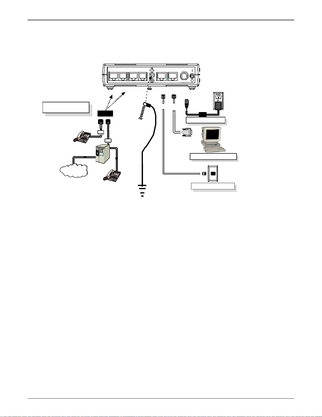
Command PC & Voip Hookups MultiVOIP FX Quick Start Guide
Quick Hookup for MVPFX2-2
Voice/Fax Channel 1 - 2
Connections
PSTN
VOICE/FAX 1 WAN CONSOLE
FXS FXSFXO FXO
FXS FXO
Connectors
VOICE/FAX 2 POWER
RJ-11
GND
FX S
FXO
10/100 RS- 232
RJ-45
Connectors
Power Connection
DB-9 Connector
to
Computer Serial Port
Console Port Connection
WAN/ Ethernet Co nnect ion
20
Page 21
Auxiliary Software Issues MultiVOIP FX Quick Start Guide
Ensure that Java & Browser Versions will Support Web-Based GUI
For more details, see Chapter 4: Software Installation in User Guide.
1. MultiVOIP must be properly cabled. Power must be turned on.
2. Is Java Runtime program at level 1.5 or greater? If not, load up-to-date Java version from MultiVOIP CD
or from Java web site.
3. Is web browser of a sufficiently recent version to support MultiVOIP web GUI? (The browser must be
Internet Explorer 6.0(+), Netscape 6.0(+), or FireFox 1.0(+).) If not, download a browser version that is
new enough to support the web GUI.
4. Browse to IP address of MultiVOIP unit (default is 192.168.2.1).
5. If username and password have been established, enter them when prompted by voip.
6. Use web browser GUI to continue with configuration and operation of voip.
Changing the IP Address through the Console Connection
At its initial bootup, the default IP address of the MultiVOIP is 192.168.2.1. If you are not able to access the web GUI
through this IP address (192.168.2.1), then use the procedure below to set a valid IP for operation of th e MultiVOIP on your
network.
This procedure also works if the IP address is forgotten.
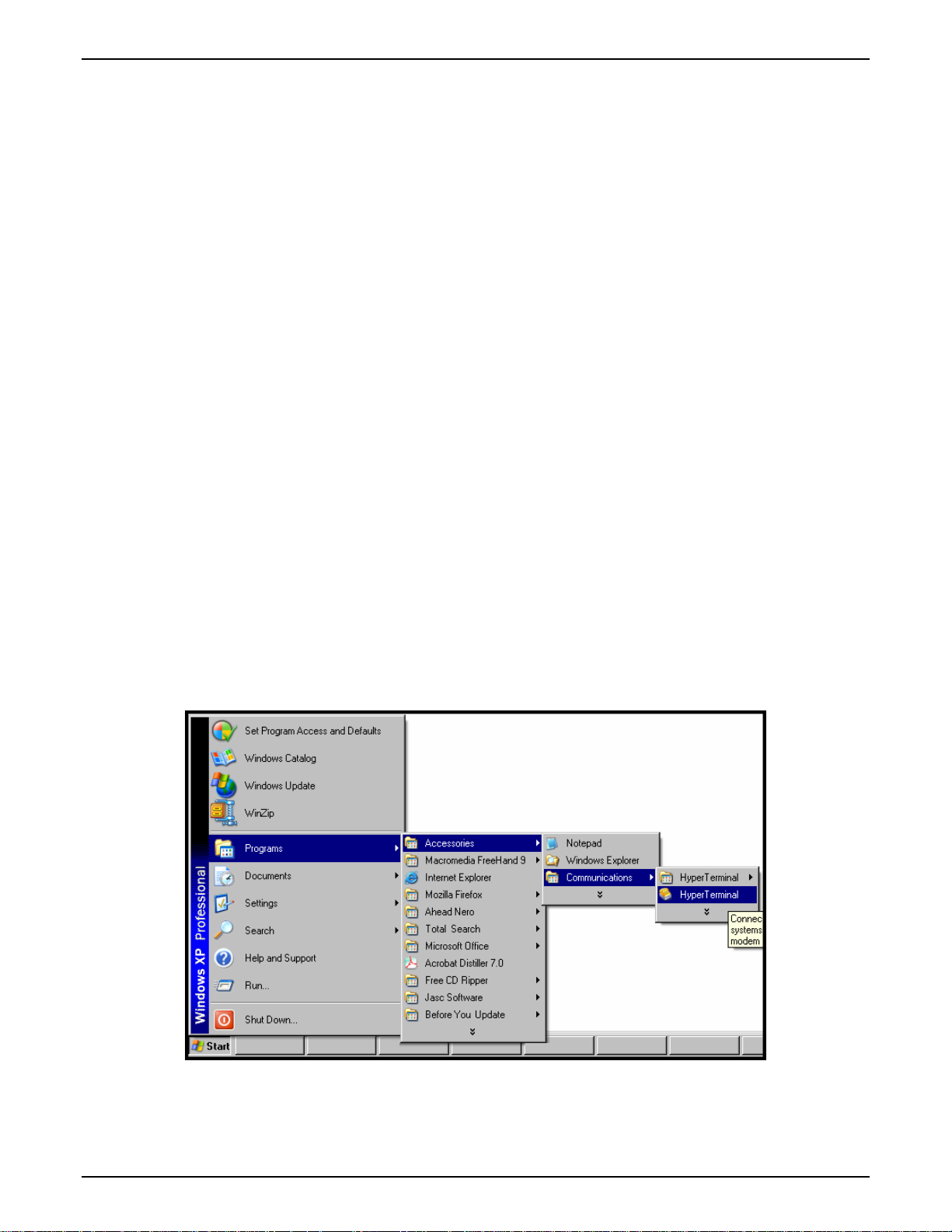
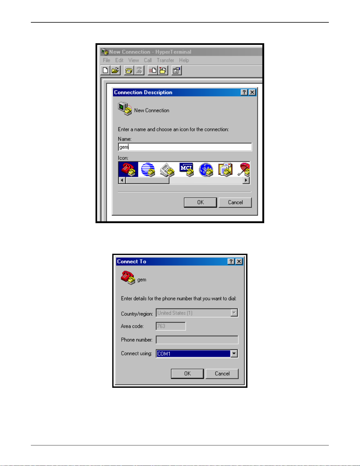
1. Connect a cable between the MultiVOIP’s “Console” connector and a serial cable on the computer.
2. Launch HyperTerminal or a similar communications program.
21
Page 22
Phone/IP Starter Config. MultiVOIP FX Quick Start Guide
3. Establish a ‘connection’ in HyperTerminal.
4. Check that HyperTerminal is addressing the correct COM port.
22
Page 23
MultiVOIP FX Quick Start Guide Phone/IP Starter Config.
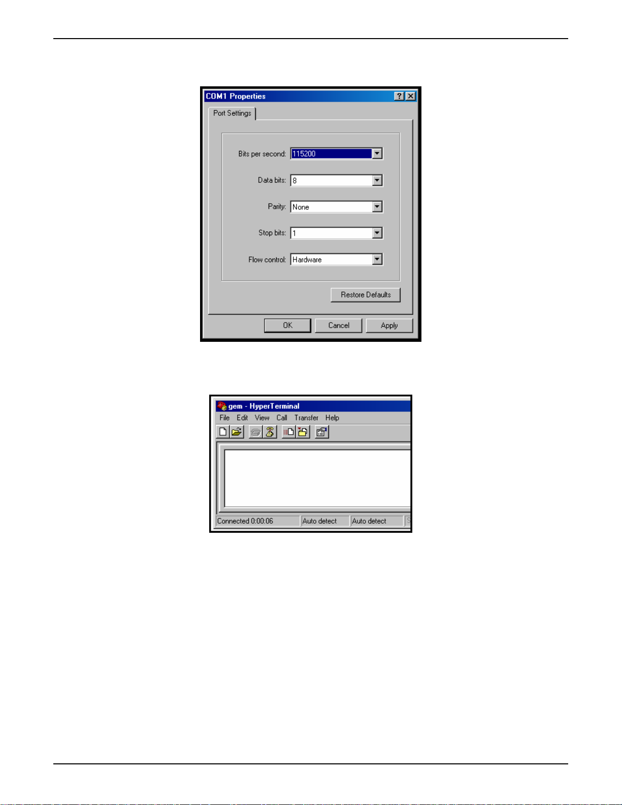
5. Check that HyperTerminal’s data rate is set to 115200bps.
6. To begin, HyperTerminal must be connected and ready.
23
Page 24
Phone/IP Starter Config. MultiVOIP FX Quick Start Guide
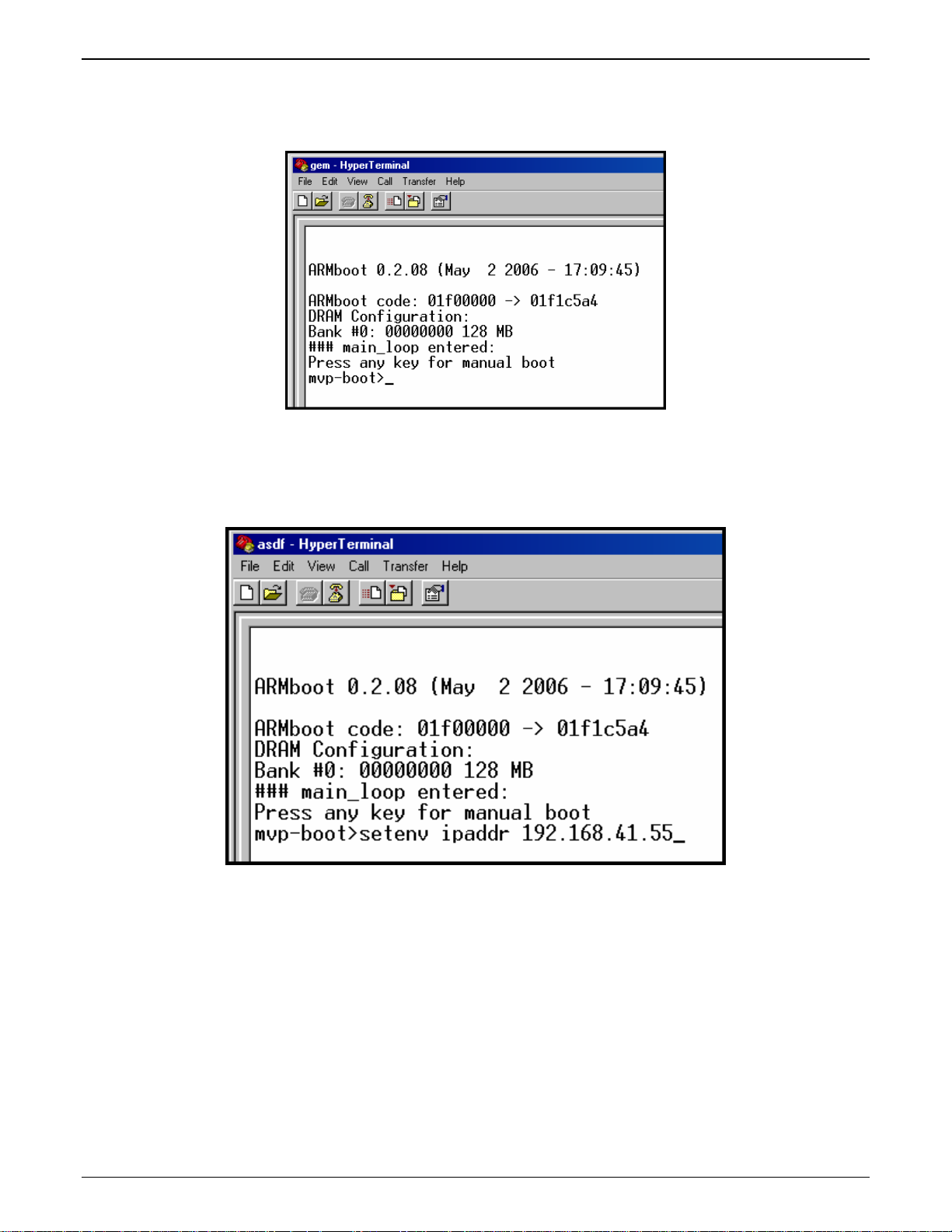
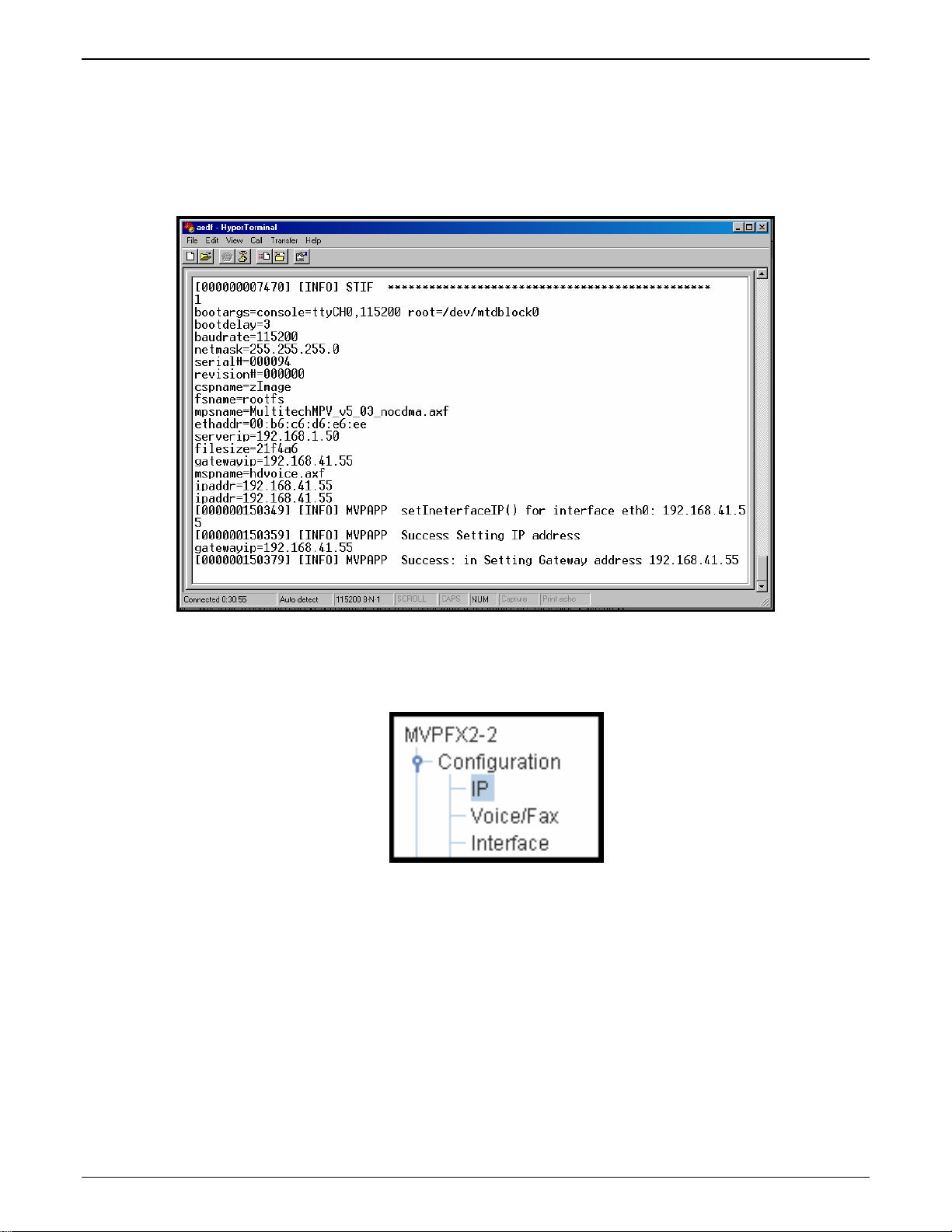
7. Reboot the MultiVOIP by turning off its power and turning it back on again.
The ARMBoot prompt will appear on the HyperTerminal screen.
When this screen appears, you must quickly press any key to stop the regular boot-up process (the manual
boot process).
8. Type setenv ipaddr a.b.c.d where a, b, c, & d are the octet values for the desired IP address of the voip.
Press Enter.
Note: When using the setenv command, be careful in your spelling. If you mis-spell ipaddr as “ipadde” for
example, the ARMBoot program will create a new and useless variable entitled ipadde and will not change
the value of the ipaddr variable.
24
Page 25
MultiVOIP FX Quick Start Guide Phone/IP Starter Config.
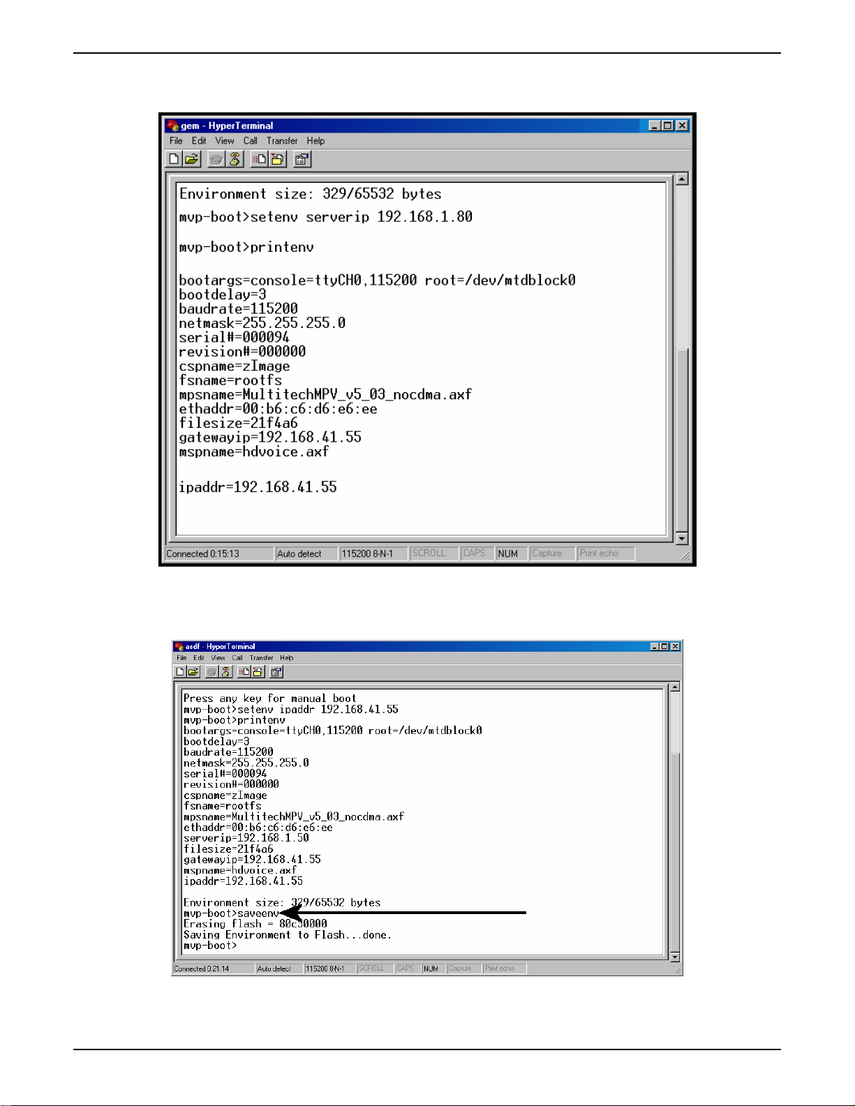
9. To confirm that the ipaddr (voip IP address) was indeed changed to the value you want, type printenv at the
mvp-boot> prompt and then press Enter.
10. Type saveenv and press Enter.
11. Turn the voip off and then on again to reboot it.
25
Page 26
Phone/IP Starter Config. MultiVOIP FX Quick Start Guide
12. Allow the voip to boot up again normally (this will take a few minutes) with the console connection still
active. When the rebooting process is complete (when the boot light is no longer lit), type 1 and press
Enter.
NOTE: This change of IP address is only temporary. You must complete this procedure to make the
change of IP address permanent.
13. Use a web browser to browse to the voip using the IP address that you have just assigned.
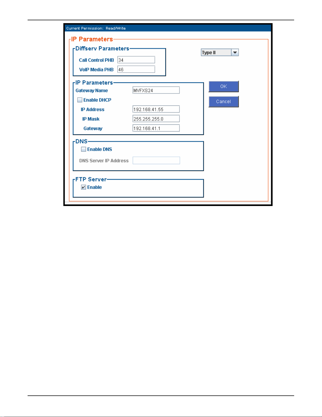
14. In the web browser, click on IP Parameters in the sidebar list.
In each field, enter the values that fit your particular network.
26
Page 27
MultiVOIP FX Quick Start Guide Phone/IP Starter Config.
Click OK.
15. In the sidebar menu, click Save & Apply. Allow the voip to Reboot.
27
Page 28

Phone/IP Starter Config. MultiVOIP FX Quick Start Guide
Phone/IP Starter Configuration
Full details here:
MVPFX2-2
MVPFX2-4
MVPFX2-8
1. Open a browser and go to the IP Address of the MVPFX2 unit. In the sidebar menu click Configuration.
2. Go to Configuration | IP. Enter or alter any IP Parameters, as needed. Click OK.
3. Go to Configuration | Voice/Fax. Select Coder | “Automatic.” At the right-hand side of the dialog box,
click OK. If you know any specific parameter values that will apply to your system, enter them. Click
Copy Channel. Select Copy to All. Click Copy. At main Voice/Fax Parameters screen, click OK to exit
from the dialog box.
4. Enter telephone system information. Go to Configuration | Interface. Enter parameters obtained from
phone company or PBX administrator. Click OK.
5. Go to Configuration | Regional Parameters. Select the Country/Region that fits your situation. Click
OK and confirm. Click OK to exit from the dialog box.
6. Go to Configuration | Logs/Traces.
Select “Enable Console Messages.” Click OK.
To do logging with a SysLog client program, click on “SysLog Server – Enable” in the Logs/Traces screen.
To implement this function, you must install a SysLog client program. For more info, see the “SysLog
Server Functions” section of the Operation & Maintenance chapter of the
7. Go to Save &Apply. Click OK. This will save the parameter values that you have just entered.
The MultiVOIP’s “BOOT” LED will light up while the configuration file is being saved and loaded into
the MultiVOIP. Don’t do anything to the MultiVOIP until the “BOOT “LED is off (a loss of power at this
point could cause the MultiVOIP unit to lose the configuration settings you have made).
Technical Configuration chapter
in User Guide
User Guide.
END OF PROCEDURE.
28
Page 29

MultiVOIP FX Quick Start Guide Phonebook Starter Config.
Phonebook Starter Configuration (with remote voip)
If the topic of voip phone books is new to you, it may be helpful to read the PhoneBook Tips section (page
34) before starting this procedure.
To do this part of the quick setup, you need to know of another voip that you can call to conduct a test.
Ideally, a test of two voips at the same physical location connected back-to-back should be done first. A
secondary test should be done between two voips at different locations, typically with one voip located
somewhere outside of your building. You must know the phone number and IP address for that site. We
are assuming here that the MultiVOIP will operate in conjunction with a PBX.
You must configure both the Outbound Phonebook and the Inbound Phonebook. A starter configuration
only means that two voip locations will be set up to begin the system and establish voip communication.
Outbound Phonebook
1. Open the browser and go to the IP address of the MultiVOIP unit. In the sidebar menu, select Phone
Book
2. Go to Outbound Phonebook | Add Entry.
3. On a sheet of paper, write down the calling code of the remote voip (area code, country code, city code,
etc.) that you’ll be calling.
Follow the example that best fits your situation.
North America,
Long-Distance Example
Technician in Seattle (area
206) must set up one voip
there, another in Chicago
(area 312, downtown).
Answer: Write down 312.
Euro, National Call
Example
Technician in central
London (area 0207) to set
up voip there, another in
Birmingham (area 0121).
Answer: write down 0121.
Euro, International Call Example
Technician in Rotterdam (country 31; city 010) to
set up one voip there, another in Bordeaux
(country 33; area 05).
Answer: write down 3305.
29
Page 30

Phonebook Starter Config. MultiVOIP FX Quick Start Guide
4. Suppose you want to call a phone number outside of your building using a phone station that is an
extension from your PBX system (if present). What digits must you dial? Often a “9” or “8” must be
dialed to “get an outside line” through the PBX (i.e., to connect to the PSTN). Generally, “1 “or “11” or
“0” must be dialed as a prefix for calls outside of the calling code area (long-distance calls, national calls,
or international calls).
On a sheet of paper, write down the digits you must dial before you can dial a remote area code.
North America,
Long-Distance Example
Seattle-Chicago system.
Seattle voip works with
PBX that uses “8” for all
voip calls. “1” must
immediately precede area
code of dialed number.
Answer: write down 81.
Euro, National Call
Example
London/Birming. system.
London voip works with
PBX that uses “9” for all
out-of-building calls
whether by voip or by
PSTN. “0” must
immediately precede area
code of dialed number.
Answer: write down 90.
Euro, International Call Example
Rotterdam/Bordeaux system.
Rotterdam voip works with PBX where “9” is
used for all out-of-building calls. “0” must
precede all international calls.
Answer: write down 90.
5. In the “Destination Pattern” field of the Outbound Phone Book Add Entry screen, enter the digits from
step 4 followed by the digits from step 3.
North America,
Long-Distance Example
Seattle-Chicago system.
Answer: enter 81312 as
Destination Pattern in Outbound
Phone-book of
Seattle voip.
Euro, National Call
Example
London/Birming. system.
Leading zero of
Birmingham area code is
dropped when combined
with national-dialing
access code. (Such
practices vary by country.)
Answer: enter 90121 as
Destination Pattern in Outbound
Phonebook of
London voip.
Not 900121.
Euro, International Call Example
Rotterdam/Bordeaux system.
Answer: enter 903305 as Destination Pattern in
Outbound Phonebook of Rotterdam voip.
30
Page 31

MultiVOIP FX Quick Start Guide Phonebook Starter Config.
6. In the “Remove Prefix” field, enter the initial PBX access digit (“8” or “9”).
North America,
Long-Distance Example
Seattle-Chicago system.
Answer: enter 8 in “Remove
Prefix” field of
Seattle Outbound
Phonebook.
Euro, National Call
Example
London/Birming. system.
Answer: enter 9 in “Remove
Prefix” field of
London Outbound
Phonebook.
Euro, International Call Example
Rotterdam/Bordeaux system.
Answer: enter 9 in “Remove Prefix” field of Outbound
Phonebook for Rotterdam voip.
Some PBXs will not ‘hand off’ the “8” or “9” to the voip. But for those PBX units that do, it’s important to enter the
“8” or “9” in the “Remove Prefix” field in the Outbound Phonebook. This precludes the problem of having to make
two inbound phonebook entries at remote voips, one to account for situations where “8” is used as the PBX access
digit, and another for when “9” is used.
7. If you intend to use a SIP Proxy, enter the relevant information in the Call Signaling screen.
8. Enter the IP address of the MultiVOIP that you want to call.
9. Click OK. to exit from the Outbound Phonebook Add Entry screen.
31
Page 32

Phonebook Starter Config. MultiVOIP FX Quick Start Guide
Inbound Phonebook
1. Open the browser and go to the IP address of the MultiVOIP unit.
2. Go to Phone Book | Inbound Phonebook | Add Entry.
3. In the “Remove Prefix” field, enter your local calling code (area code, country code, city code, etc.)
preceded by any other “access digits” that are required to reach your local site from the remote voip
location (think of it as though the call were being made through the PSTN – even though it will not be).
North America,
Long-Distance Example
Seattle-Chicago system.
Seattle is area 206. Chicago
employees must dial 81
before dialing any Seattle
number on the voip system.
Answer: 1206 is prefix to be
removed by local
(Seattle) voip.
Euro, National Call
Example
London/Birming. system.
Inner London is 0207 area.
Birmingham employees must
dial 9 before dialing any
London number on the voip
system.
Answer: 0207 is prefix to be
removed by local
(London) voip.
Euro, International Call Example
Rotterdam/Bordeaux system.
Rotterdam is country code 31, city code 010. Bordeaux
employees must dial 903110 before dialing any
Rotterdam number on the voip system.
Answer: 03110 is prefix to be removed by local
(Rotterdam) voip.
32
Page 33

MultiVOIP FX Quick Start Guide Phonebook Starter Config.
4. In the “Add Prefix” field, enter any digits that must be dialed from your local voip to gain access to the
PSTN.
North America,
Long-Distance Example
Seattle-Chicago system.
On Seattle PBX, “9” is used to
get an outside line.
Answer: 9 is prefix to be
added by local
(Seattle) voip.
Euro, National Call
Example
London/Birming. system.
On London PBX, “9” is used
to get an outside line.
Answer: 9 is prefix to be
added by local
(London) voip.
Euro, International Call Example
Rotterdam/Bordeaux system.
On Rotterdam PBX, “9” is used to get an outside line.
Answer: 9 is prefix to be added by local (Rotterdam)
voip.
5. In the “Channel Number” field, enter “Hunting.” A “hunting” value means the voip unit will assign the
call to the first available channel. If desired, specific channels can be assigned to specific incoming calls
(i.e., to any set of calls received with a particular incoming dialing pattern).
6. In the “Description” field, it is useful to describe the ultimate destination of the calls. For example, in a
New York City voip system, “incoming calls to Manhattan office,” might describe a phonebook entry, as
might the descriptor “incoming calls to NYC local calling area.” The description should make the routing
of calls easy to understand. (40 characters max.)
North America,
Long-Distance Example
Seattle-Chicago system.
Possible Description:.
Free Seattle access, all
employees
Euro, National Call
Example
London/Birming. system.
Possible Description:.
Local-rate London access,
all empl.
Euro, International Call Example
Rotterdam/Bordeaux system.
Possible Description:. Local-rate Rotterdam access, all
empl.
7. Repeat steps 2-6 for each inbound phonebook entry. When all entries are complete, go to step 8.
8. Click OK to exit the inbound phonebook screen.
9. Click on Save & Apply. Click OK. Then click Reboot Voip.
Your starter inbound phonebook configuration is complete.
33
Page 34

Phonebook Tips MultiVOIP FX Quick Start Guide
Phonebook Tips
Preparing the phonebook for your voip system is a complex task that, at first, seems quite daunting. These
tips may make the task easier.
1.
Use Dialing Patterns, Not Complete Phone Numbers. You will not generally enter complete phone numbers
in the voip phonebook. Instead, you’ll enter “destination patterns” that involve area codes and other digits.
If the destination pattern is a whole area code, you’ll be assigning all calls to that area code to go to a
particular voip which has a unique IP address. If your destination pattern includes an area code plus a
particular local phone exchange number, then the scope of calls sent through your voip system will be
narrowed (only calls within that local exchange will be handled by the designated voip, not all calls in that
whole area code). In general, when there are fewer digits in your destination pattern, you are asking the
voip to handle calls to more destinations.
2.
The Four Types of Phonebook Digits Used. Important!
“Destination patterns” to be entered in your phonebook will generally consist of:
(a) calling area codes,
(b) access codes,
(c) local exchange numbers, and
(d) specialized codes.
Although voip phonebook entries may look confusing at first, it’s useful to remember that all the digits in
any phonebook entry must be of one of these four types.
(a)
calling area codes. There are different names for these around the world: “area codes,” “city codes,”
“country codes,” etc. These codes, are used when making non-local calls. They always precede the phone
number that would be dialed when making a local call.
(b)
access codes. There are digits (PSTN access codes) that must be dialed to gain access to an operator, to
access the publicly switched ‘long-distance’ calling system(North America), to access the publicly switched
‘national’ calling system (Europe and elsewhere), or to access the publicly switched ‘international’ calling
system (worldwide).
There are digits (PBX access codes) that must be dialed by phones connected to PBX systems or key systems.
Often a “9” must be dialed on a PBX phone to gain access to the PSTN (‘to get an outside line’). Sometimes
“8” must be dialed on a PBX phone to divert calls onto a leased line or to a voip system. However,
sometimes PBX systems are ‘smart’ enough to route calls to a voip system without a special access code (so
that “9” might still be used for all calls outside of the building).
There are also digits (special access codes) that must be dialed to gain access to a particular discount longdistance carrier or to some other closed or proprietary telephone system.
(c)
local exchange numbers. Within any calling area there will be many local exchange numbers. A single
exchange may be used for an entire small town. In cities, an exchange may be used for a particular
neighborhood (although exchanges in cities do not always cover easily discernible areas). Organizations
like businesses, governments, schools, and universities are also commonly assigned exchange numbers for
their exclusive use. In some cases, these organizational-assigned exchanges can become non-localized
because the exchange is assigned to one facility and linked, by the organization’s private network, to other
sometimes distant locations.
(d)
specialized codes. Some proprietary voip units assign, to sites and phone stations, numbers that are not
compatible with PSTN numbering. This can also occur in PBX or key systems. These specialized numbers
must be handled on a case-by-case basis.
34
Page 35

MultiVOIP FX Quick Start Guide Phonebook Tips
3.
Knowing When to Drop Digits. Example
When calling area codes and
access codes are used in
combination, a leading “1” or “0”
must sometimes be dropped.
Phonebook Entry
4.
Using a Comma. Detail
Commas are used in telephone
dialing strings to indicate a pause
to allow a dial tone to appear
(common on PBX and key
systems). Commas may be used
only in the “Add Prefix” field of
the Inbound Phonebook.
Area code for Inner London is
listed as “0207.” However, in
international calls the leading
“0” is dropped.
International
Access Code
, = 1-second pause
in many PBX systems
(not needed in all)
U.K.
Country
Code
Leading Zero
Dropped from
Area Code
5.
Ease of Use. The phonebook setup determines how easy the voip system is to use. Generally, you’ll
want to make it so dialing a voip call is very similar to dialing any other number (on the PSTN or through
the PBX).
6.
Avoid Unintentional Calls to Official/Emergency Numbers. Dialing a voip call will typically be somewhat
different than ordinary dialing. Because of this, it’s possible to set up situations, quite unwittingly, where
phone users may be predisposed to call official numbers without intending to do so. Conversely, a
voip/PBX system might also make it difficult to place an official/emergency call when one intends to do so.
Study your phonebook setup and do some test-dialing on the system to avoid these pitfalls.
7.
Inbound/Outbound Pattern Matching. In general, the Inbound Phonebook entries of the local voip unit will
match the Outbound Phonebook entries of the remote voip unit. Similarly, the Outbound Phonebook
entries of the local voip unit will match the Inbound Phonebook entries of the remote voip unit. There will
often be non-matching entries, but it’s nonetheless useful to notice the matching between the phonebooks.
8.
Simulating Network in-lab/on-benchtop. One common method of configuring a voip network is to set up a
local IP network in a lab, connect voip units to it, and perhaps have phones connected on channel banks to
make test calls.
35
Page 36

Phonebook Example MultiVOIP FX Quick Start Guide
Phonebook Example
Boise Office
PBX System.
Main Number:
333-2700
(MVPFX2-8)
Inbound Phonebook
Inbound Phonebook
Each
two entries. The first entry (4 digits)
specifies how incoming calls from the
ot her vo ip sit es w il l be han d led if
they go out ont o the local PST N .
Essentially, all those calls come to the
receiving voip with a pattern
beginnin g w it h
voip removes those four digits
becau se t h ey aren ’t need ed w hen
dialing locally. The local voip
at t ach es a “ 9” at t he beg i nni ng of th e
nu mber t o get an out si d e l i ne. T he
PBX then completes the call to the
PSTN .
The second Inbound Ph on ebook ent ry
(1 digit) is for receiving calls from
com p any emp loy ees i n t he o t h er tw o
citi es. The out-of -tow n empl oyee
si m p ly di als 3 d ig i ts. T h e f ir st of t he
three digits is uniquely used at each
si t e and so act s as a d est i n at io n
pat t er n (Bo ise ext ensi on s ar e 7xx,
Sant a Fe ex t en si ons 2x x, Fl agst af f
extensions 6xx).
The local voip sees the pattern in its
inbound phone book and notes the
first digit (here either 2, 5, or 6).
To make the match, this first digit,
2, 5, or 6 is pu t i n the “ Remov e Pref i x”
field. This first digit must then be
added back once agai n so t h at t he
voip will send all three digits to the
PBX. The PBX can then dial the
specific extension identified by the
three-digit number.
Area: 208
40 extensions
204.16.49.73
8-Channel
VoIP
contai ns
1+area code. T he l ocal
Flagstaff Office
Area: 520
204.16.49.75
2-Channel
Analog VoIP
(MVPFX2-2)
PSTN
One Common Situation
V oip Exam p l e. This company has offices in three
d i ff er ent ci ti es. T h e PBX u ni ts al l op er ate al ik e.
Notably, they all give access to outside lines using
“9.” They all are ‘smart’ enough to identify voip calls
without using a special access digit (“ 8” is used in
som e system s). Fi nal l y, t he sy stem op er ates so t h at
emp l oy ees i n an y of f i ce can d i al emp loy ees i n any
other off ice using onl y thr ee d igits. Here are the
p h o n eb o o k s need ed f or th at sy st em .
Santa Fe Office
Area: 505
204.16.49.74
4-Channel
Analog VoIP
(MVPFX2-4)
IP
Network
Each
Outbound Phonebook
pairs of entries, two entries for each
r em ote si te. W hen ev er an ou t -of - tow n
em p l o y ee di al s a 12-d i g i t nu m ber
beginning w it h the listed 5-digi t
destination pattern (9+1+area code) of
anot her com pan y locati on , the PBX
hands the call to the voip system. The
local voip strips off the “9” and directs
t h e cal l t o t h e I P ad d r ess of t he r em ot e
voip. The remote voip receives the call
and hands it to its PBX. The PBX then
completes the call to the PSTN.
The one- d i gi t
patterns pertain to 3-digit calling
bet w een co m pany emp loy ees.
PBX System.
Main Number:
444-3200
PSTN
Outbound
20 extensions
con t ai ns t w o
destination
PBX System.
Main Number:
777-5600
10 extensions
PSTN
36
Page 37

MultiVOIP FX Quick Start Guide Phonebook Example
Voip Sites with Phonebooks
Boise Office
PBX System.
Main Number:
333-2700
Area: 208
PSTN
40 extensions
Inbound Phonebook Outbound Phonebook
Prefix to
Remove
91208 9, Incoming calls
7 7 i ncoming calls
204.16.49.73
8-Channel
VoIP
(MVPFX2-8)
IP
Network
Santa Fe Voip Santa Fe Voip
Inbound Phonebook Outbound Phonebook
Prefix
to Add
Description
Incoming Calls
to PSTN,
Santa Fe local
calls
to extensions
of company’s
PBX system
in Santa Fe
Prefix to
Remove
91505 9, Incoming calls
2 2 Incoming calls
Total
Digits
Prefix to
Remove
Destin.
Pattern
91208 12 none none 204.
7 3 none none 204.
91520 12 none none 204.
6 3 none none 204.
Boise Voip Boise Voip
Prefix
to Add
Description
Incoming Calls
to PSTN,
Boise Area
to extensions
of company’s
PBX system
in Boise
Total
Prefix to
Destin.
Digits
Pattern
91505 12 none none
2 3 none none
91520 12 none none 204.
6 3 none none 204.
Remove
Prefix
to AddIPAddr
Santa Fe Office
Prefix
to AddIPAddr
16.49.
73
16.49.
73
16.49.
75
16.49.
75
Description
Outgoing Calls
Outgoing calls
to Boise area
3-digit calls to
Boise
employees
(extensions
700-790)
Outgoing calls
to Flagstaff
area
3-digit calls to
Flagstaff
employees
(extensions
600-630)
PBX System.
Main Number:
444-3200
204.
16.49.
74
204.
16.49.
74
16.49.
75
16.49.
75
Area: 505
204.16.49.74
(MVPFX2-4)
PSTN
Description
Outgoing Calls
Outgoing calls
to Santa Fe
area
3-digit calls to
Santa Fe
employees
(extensions
200 to 240)
Outgoing calls
to Flagstaff
area
3-digit calls to
Flagstaff
employees
(extensions
600-630)
4-Channel
VoIP
20 extensions
Flagstaff Office
Area: 520
204.16.49.75
2-Channel
VoIP
(MVPFX2-2)
PBX System.
Main Number:
777-5600
10 extensions
PSTN
Flagstaff Voip Flagstaff Voip
Inbound Phonebook Ou tbound Phonebook
Prefix
to Add
Description
Incoming Calls
to PSTN,
Flagstaff local
calls
to extensions
of company’s
PBX system
in Flagstaff
Prefix to
Remove
91520 9 Incoming calls
6 6 Incoming calls
Total
Digits
Prefix to
Remove
Destin.
Pattern
91505 12 none none
2 3 none none
91208 12 none none
7 3 none none
Prefix
to AddIPAddr
204.16
.49.74
204.16
.49.74
204.16
.49.73
204.16
.49.73
Description
Outgoing Calls
Outgoing calls
to Santa Fe
area
3-digit calls to
Santa Fe
employees
(extensions
200-240)
Outgoing calls
to Boise area
3-digit calls to
Boise
employees
(extensions
700-790)
37
Page 38

Phonebook Example MultiVOIP FX Quick Start Guide
Sample Phonebooks Enlarged
Boise Voip Boise Voip
Inbound Phonebook Outbound Phonebook
Prefix
Prefi x to
Remove
to Add
Description
Incoming Calls
91208 9, Incoming calls
to PSTN,
Boise Area
7 7 i ncoming calls
to extensions
of company’s
PBX system
in Boise
Santa Fe Voip Santa Fe Voip
Inbound Phonebook Outbound Phonebook
Prefix to
Remove
91505 9, Incoming calls
2 2 Incoming calls
Prefix
to Add
Destin.
Pattern
91505 12 none none
2 3 none none
91520 12 none none 204.
6 3 none none 204.
Description
Incoming Calls
to PSTN,
Santa Fe local
calls
to extensions
of company’s
PBX system
in Santa Fe
Total
Digits
Prefix to
Remove
Prefix
to AddIPAddr
204.
16.49.
74
204.
16.49.
74
Description
Outgoing Calls
Outgoing calls
to Santa Fe
area
3-digit calls to
Santa Fe
employees
(extensions
200 to 240)
Outgoing calls
to Flagstaff
16.49.
area
75
3-digit calls to
Flagstaff
16.49.
employees
75
(extensions
600-630)
Destin.
Pattern
Digits
Prefix to
Remove
Prefix
to AddIPAddr
Total
91208 12 none none 204.
7 3 none none 204.
91520 12 none none 204.
6 3 none none 204.
16.49.
73
16.49.
73
16.49.
75
16.49.
75
Description
Outgoing Calls
Outgoing calls
to Boise area
3-digit calls to
Boise
employees
(extensions
700-790)
Outgoing calls
to Flagstaff
area
3-digit calls to
Flagstaff
employees
(extensions
600-630)
Flagstaff Voip Flagstaff Voip
Inbound Phonebook Outbound Phonebook
Prefix to
Remove
91520 9 Incoming calls
6 6 Incoming calls
Prefix
to Add
Description
Incoming Calls
to PSTN,
Flagstaff local
calls
to extensions
of company’s
PBX system
in Flagstaff
Destin.
Pattern
Digits
Prefix to
Remove
Prefix
to AddIPAddr
Total
91505 12 none none
2 3 none none
91208 12 none none
7 3 none none
38
204.16
.49.74
204.16
.49.74
204.16
.49.73
204.16
.49.73
Description
Outgoing Calls
Outgoing calls
to Santa Fe
area
3-digit calls to
Santa Fe
employees
(extensions
200-240)
Outgoing calls
to Boise area
3-digit calls to
Boise
employees
(extensions
700-790)
Page 39

MultiVOIP FX Quick Start Guide Phonebook Example
Phonebook Worksheet
Voip Location/ID:____________________________
Inbound Phonebook Outbound Phonebook
Prefix
Prefix to
Remove
to Add
Other Details:
Inbound Phonebook Outbound Phonebook
Prefix to
Remove
Description
Incoming Calls
Destin.
Pattern
Voip Location/ID:____________________________
Prefix
Description
to Add
Incoming Calls
Total
Digits
Destin.
Pattern
Prefix to
Remove
Total
Digits
Prefix
to AddIPAddr
Prefix to
Remove
Description
Outgoing Calls
Prefix
to AddIPAddr
Description
Outgoing Calls
Other Details:
Voip Location/ID:____________________________
Inbound Phonebook Outbound Phonebook
Prefix
Prefix to
Remove
to Add
Description
Incoming Calls
Destin.
Pattern
Total
Digits
Prefix to
Remove
Prefix
to AddIPAddr
Description
Outgoing Calls
Other Details:
39
Page 40

Phonebook Example MultiVOIP FX Quick Start Guide
Enlarged Phonebook Worksheet
40
Page 41

MultiVOIP FX Quick Start Guide Connectivity Test
Connectivity Test
The procedures “Phone/IP Starter Configuration” and “Phonebook Starter Configuration” must be
completed before you can do this procedure.
1. These connections must be made:
MultiVOIP to local phone station
–OR--
MultiVOIP to extension of key phone
system
MultiVOIP to command PC
MultiVOIP to Internet
2. Inbound Phonebook and Outbound Phonebook must both be set up with at least one entry in each.
These entries must allow for connection between two voip units.
3. Console messages must be enabled. (If this has not been done already, go, in the MultiVOIP GUI, to
Configuration | Logs and select the “Console Messages” checkbox.
4. Make sure that the COM port connection is free so that the HyperTerminal program can use it.
5. Open the HyperTerminal program.
6. Use HyperTerminal to receive and record console messages from the MultiVOIP unit. To do so, set up
HyperTerminal as follows (setup shown is for Windows NT4; details will differ slightly in other MS
operating systems):
In the upper toolbar of the HyperTerminal screen, click on the Properties button.
In the “Connect To” tab of the Connection Properties dialog box, click on the Configure
button.
In the next dialog box, on the “General” tab, set “Maximum Speed” to 115200 bps.
On the “Connection” tab, set connection preferences to:
Data bits: 8
Parity: none
Stop bits: 1
Click OK twice to exit settings dialog boxes.
7. Make VOIP call on a local phone line accessing PSTN directly or through key system..
41
Page 42

Connectivity Test MultiVOIP FX Quick Start Guide
8. Read console messages recorded on HyperTerminal.
Console Messages from Originating VOIP. The voip unit that originates the call will send back messages
like that shown below.
[00026975] CAS[0] : RX : ABCD = 1, 1, 1, 1,Pstn State[1] TimeStamp : 26975
[00027190] CAS[0] : TX : ABCD = 1, 1, 1, 1
[00027190] PSTN: cas seizure detected on 0
[00027440] CAS[0] : TX : ABCD = 0, 0, 0, 0
[00033290] PSTN:call detected on 0 num=17637175662*
[00033290] SIP[0]:destAddr = TA:200.2.10.5:1720,NAME:Mounds
View,TEL:17637175662,17637175662
[00033290] SIP[0]:srcAddr = NAME:New York,TA:200.2.9.20
[00033440] SIP [0]:cmCallStateProceeding
[00033500] SIP[0]: Remote Information (Q931): MultiVOIP - T1
[00033565] CAS[0] : TX : ABCD = 1, 1, 1, 1
[00033675] SIP [0]: MasterSlaveStatus=Slave
[00033675] SIP[0]:FastStart Setup Not Used
[00033690] CAS[0] : TX : ABCD = 1, 1, 1, 1
[00033755] SIP[0]: Coder used 'g7231'
[00033810] PSTN:pstn call connected on 0
Console Messages from Terminating VOIP. The voip unit connected to the phone where the call is
answered will send back messages like that shown below.
[00170860] SIP[0]: New incoming call
[00170860] PSTNIF : Placing call on channel 0 Outbound digit 7175662
[00170885] CAS[0] : TX : ABCD = 1, 1, 1, 1
[00171095] SIP [0]: MasterSlaveStatus=Master
[00171105] CAS[0] : RX : ABCD = 1, 1, 1, 1,Pstn State[7] TimeStamp : 171105
[00171105] SIP[0]: Coder used 'g7231'
[00171110] SIP[0]:FastStart Setup Not Used
[00171110] SIP[0]: Already opened the outgoing logical channel
[00171110] SIP[0]: Coder used 'g7231'
[00171315] CAS[0] : RX : ABCD = 0, 0, 0, 0,Pstn State[9] TimeStamp : 171315
[00172275] PSTN: dialing digit ended on 0
[00172285] PSTN: pstn proceeding indication on 0
[00172995] CAS[0] : RX : ABCD = 1, 1, 1, 1,Pstn State[12] TimeStamp : 172995
[00173660] CAS[0] : TX : ABCD = 1, 1, 1, 1
[00173760] PSTN:pstn call connected on 0
9. When you see the following message, end-to-end voip connectivity has been achieved.
PSTN: pstn call connected on X”
“
where x is the number of the voip channel carrying the call
10. If the HyperTerminal messages do not confirm connectivity, go to the Troubleshooting procedure
below.
42
Page 43

MultiVOIP FX Quick Start Guide Troubleshooting
Troubleshooting
If you cannot establish connectivity between two voips in the system, follow the steps below to determine
the problem.
1. Ping both MultiVOIP units to confirm connectivity to the network.
2. Verify the telephone connections.
Check cabling. Are connections well seated? To correct receptacle?
Are telephone Interface Parameter settings correct?
Remember that each voip channel is separately configurable.
3. Verify phonebook configuration.
4.
Observe console messages while placing a call. Look for error messages indi-cating phonebook problems, network
problems, voice-coder mismatches, etc.
43
Page 44

4
Chapter 3: Mechanical Installation
and Cabling
4
Page 45

MultiVOIP FX User Guide Mechanical Installation & Cabling
Introduction
When MVPFX2-4 or MVPFX2-8 units are to be installed into a rack, two able-bodied persons should
participate. The MVPFX2-2 is a table-top unit that can generally be handled easily by one person.
Please read the safety notices before beginning installation.
Safety Warnings
General Safety
This product must be disconnected from its power source and from the telephone network interface when
servicing.
Lithium Battery Caution
A lithium battery on the voice/fax channel board provides backup power for the timekeeping capability.
The battery has an estimated life expectancy of ten years.
When the battery starts to weaken, the date and time may be incorrect. If the battery fails, the board must
be sent back to Multi-Tech Systems for battery replacement.
Warning: There is danger of explosion if the battery is incorrectly replaced.
Ethernet (WAN) Ports Caution
Caution: The Ethernet ports (often labeled “WAN”) are not designed to be connected to a Public
Telecommunication Network.
45
Page 46

Mechanical Installation & Cabling MultiVOIP FX User Guide
Safety Warnings Telecom
1. Never install telephone wiring during a lightning storm.
2. Never install a telephone jack in wet locations unless the jack is specifically designed for wet locations.
3. This product is to be used with UL and UL listed computers.
4. Never touch uninsulated telephone wires or terminals unless the telephone line has been disconnected at
the network interface.
5. Use caution when installing or modifying telephone lines.
6. Avoid using a telephone (other than a cordless type) during an electrical storm. There may be a remote
risk of electrical shock from lightning.
7. Do not use a telephone in the vicinity of a gas leak.
8. To reduce the risk of fire, use only a UL-listed 26 AWG or larger telecommunication line cord.
46
Page 47

MultiVOIP FX User Guide Mechanical Installation & Cabling
Unpacking Your MultiVOIP
When unpacking your MultiVOIP, check to see that all of the items shown are included in the box. For the
various MultiVOIP models, the contents of the box will be different. Study the particular illustration below
that is appropriate to the model you have purchased. If any box contents are missing, contact MultiTech
Tech Support at 1-800-972-2439.
Unpacking the MVPFX2-4/8
Quick Start
Guide
Voice/Fax over IP Networks
Voice/Fax 5 Voice/Fax 6 Voice/Fax 7 Voice/Fax 8
XMT RCV XSG RSG XMT RCV XSG RSG XMT RCV XSG RSG
Ethernet
RCV XMT COL LNK
Voic e/ Fa x 1
XMT RCV XSG RSG
Voice/Fax 2 Voice/Fax 3
XMT RCV XSG RSG
Boot
Power
XMT RCV XSG RSG
XMT RCV XSG RSG
Voice/Fax 4
XMT RCV XSG RSG
Figure 3-1: Unpacking the MVPFX2-4/8
47
Page 48

Mechanical Installation & Cabling MultiVOIP FX User Guide
Unpacking the MVPFX2-2
Figure 3-2: Unpacking the MVPFX2-2
48
Page 49

MultiVOIP FX User Guide Mechanical Installation & Cabling
Rack Mounting Instructions for
MVPFX2-4 & MVPFX2-8
The MultiVOIPs can be mounted in an industry-standard EIA 19-inch rack enclosure, as shown in Figure 3-
3.
Figure 3-3: Rack-Mounting (MVPFX2-4 or MVPFX2-8)
49
Page 50

Mechanical Installation & Cabling MultiVOIP FX User Guide
Safety Recommendations for Rack Installations of MVPFX2-4 or MVPFX2-8
Mounting: Mechanically, this unit is designed for a one-high industry standard EIA 19-inch rack enclosure. The
product must be installed by qualified service personnel in a restricted-access area, in accordance with articles
110-16, 10-17, and 110-18 of the National Electrical Code, ANSI/NFPA 70.
• Ensure proper installation of the unit in a closed or multi-unit enclosure by following the recommended
installation as defined by the enclosure manufacturer. Do not place the unit directly on top of other
equipment or place other equipment directly on top of the unit.
• If installing the unit in a closed or multi-unit enclosure, ensure adequate airflow within the rack so that
the maximum recommended ambient temperature is not exceeded.
• Ensure that the unit is properly connected to earth ground by verifying that it is reliably grounded when
mounted within a rack. If a power strip is used, ensure that the power strip provides adequate grounding
of the attached apparatus.
• When mounting the equipment in the rack, make sure mechanical loading is even to avoid a hazardous
condition, such as loading heavy equipment in rack unevenly. The rack used should safely support the
combined weight of all the equipment it supports.
• Ensure that the mains supply circuit is capable of handling the load of the equipment. See the power
label on the equipment for load requirements (full specifications for MultiVOIP models are presented in
chapter 1 of this manual).
• Maximum ambient temperature for the unit is 60 degrees Celsius (140 degrees Fahrenheit) at 20-90% noncondensing relative humidity.
• This equipment should only be installed by properly qualified service personnel.
• Only connect like circuits. In other words, connect SELV (Secondary Extra Low Voltage) circuits to SELV
circuits and TN (Telecommunications Network) circuits to TN circuits.
• To reduce the risk of shock, all access doors should be closed during normal operation of the equipment.
50
Page 51

MultiVOIP FX User Guide Mechanical Installation & Cabling
19-Inch Rack Enclosure Mounting Procedure
Attaching the MultiVOIP to a rack-rail of an EIA 19-inch rack enclosure will certainly require two persons.
Essentially, the technicians must attach the brackets to the MultiVOIP chassis with the screws provided, as
shown in Figure 3-4, and then secure unit to rack rails by the brackets, as shown in Figure 3-5. Because
equipment racks vary, screws for rack-rail mounting are not provided. Follow the instructions of the rack
manufacturer and use screws that fit.
1. Position the right rack-mounting bracket on the MultiVOIP using the two vertical mounting
screw holes.
2. Secure the bracket to the MultiVOIP using the two screws provided.
3. Position the left rack-mounting bracket on the MultiVOIP using the two vertical mounting screw
holes.
4. Secure the bracket to the MultiVOIP using the two screws provided.
5. Remove feet (4) from the MultiVOIP unit.
6. Mount the MultiVOIP in the rack enclosure per the rack manufacture’s mounting procedure.
x
x
Figure 3-4: Bracket Attachment for Rack Mounting
(MVPFX2-4 & MVPFX2-8)
Figure 3-5: Attaching MultiVOIP to Rack Rail
(MVPFX2-4 & MVPFX2-8)
51
Page 52

Mechanical Installation & Cabling MultiVOIP FX User Guide
Cabling Procedure for MVPFX2-4/8
Cabling involves connecting the MultiVOIP to your LAN and telephone equipment.
1. Connect the power cord supplied with your MultiVOIP to a live AC outlet and to the power connector on
the back of the MultiVOIP as shown at top right in Figure 3-6.
Grounding
Screw
PSTN
Voice/Fax Channel Connections
Ch anne ls 1- 4 Le ft-Mo s t; fo r MVPFX 2-4/8
Channels 5-8 Right-Most; for MVPFX2-8 only
FXO
RJ-11
Connectors
FXS FXO
FXS
RJ-45
Connectors
DB- 9 Co n n e cto r to
Computer Serial Port
for Console Functions
Console Port Connection
WAN/Ethernet Connection
Grounding
Cable
VOIP Control
through
Web G UI
Figure 3-6: Cabling for MVPFX-4/8
2. Connect the MultiVOIP to a PC by using an RF-45 (male) to DB-9 (female) cable. Plug the RJ-45 end of the
cable into the Console port of the MultiVOIP and the other end into the PC serial port. See Figure 3-6.
3. Connect a network cable to the WAN 10/100 connector on the back of the MultiVOIP. Connect the other
end of the cable to your network switch.
4. For an FXS connection: Examples - analog phone, fax machine,
Key Telephone System
Connect one end of an RJ-11 phone cord to the Channel 1 FXS connector on the
back of the MultiVOIP. Connect the other end to the device.
For an or FXO connection: Examples - PBX extension, POTS line from telco central office
Connect one end of an RJ-11 phone cord to the Channel 1 FXO connector on
the back of the MultiVOIP. Connect the other end to the phone jack.
52
Page 53

MultiVOIP FX User Guide Mechanical Installation & Cabling
5. Repeat step 4 to connect the remaining telephone equipment to each channel on your MultiVOIP.
Although a MultiVOIP’s channels are often all configured identically, each channel is individually
configurable. So, for example, some channels of a MultiVOIP might use the FXO interface and others the
FXS.
6. Ensure that the unit is properly connected to earth ground by verifying that it is reliably grounded when
mounted within a rack.
This can be accomplished by connecting a grounding wire between the chassis grounding screw (see
Figure 3-6) and a metallic object that will provide an electrical ground.
7. Turn on power to the MultiVOIP by placing the ON/OFF switch on the back panel to the ON position.
Wait for the Boot LED on the MultiVOIP to go off before proceeding. This may take a few minutes.
With the connections made, you are ready to contact the web GUI and begin configuring the MultiVOIP.
Cabling Procedure for MVPFX2-2
Cabling involves connecting the MultiVOIP to your LAN and telephone equipment.
1. Connect the power cord supplied with your MultiVOIP to the power connector on the back of the
MultiVOIP and to a live AC outlet as shown in Figure 3-7.
Voice/Fax Channel 1 - 2
Connections
VOICE/FAX 1 WAN CONSOLE
FXS FXSFXO FXO
FXS FXO
Connectors
VOICE/FAX 2 POWER
RJ-11
10/100 RS- 232
RJ-45
Connectors
Power Connection
GND
FX S
FXO
PSTN
DB-9 Connector
to
Computer Serial Port
Console Port Connection
WAN/ Ethernet Co nnect ion
Figure 3-7: Cabling for MVPFX2-2
2. Connect the MultiVOIP to a PC by using a RJ-45 (male) to DB-9 (female) cable. Plug the RJ-45 end of the
cable into the Console port of the MultiVOIP and the other end into the PC serial port. See Figure 3-7.
3. Connect a network cable to the WAN 10/100 connector on the back of the MultiVOIP. Connect the other
end of the cable to your network switch.
53
Page 54

Mechanical Installation & Cabling MultiVOIP FX User Guide
4. For an FXS connection: Examples - analog phone, fax machine,
Key Telephone System
Connect one end of an RJ-11 phone cord to the Channel 1 FXS connector on the
back of the MultiVOIP. Connect the other end to the device or phone jack.
For an or FXO connection: Examples - PBX extension, POTS line from telco central office
Connect one end of an RJ-11 phone cord to the Channel 1 FXO connector on
the back of the MultiVOIP. Connect the other end to the device or phone
jack.
5. Repeat the above step to connect the remaining telephone equipment to the second channel on your
MultiVOIP.
6. Ensure that the unit is properly connected to earth ground by verifying that it is reliably grounded when
mounted within a rack.
This can be accomplished by connecting a grounding wire between the chassis and a metallic object that
will provide an electrical ground.
7. Turn on power to the MultiVOIP by placing the ON/OFF switch on the back panel to the ON position.
Wait for the BOOT LED on the MultiVOIP to go off before proceeding. This may take a few minutes.
Proceed to the MultiVOIP & Auxiliary Software chapter for considerations about the Java and browser
requirements in relation to the MultiVOIP web GUI.
54
Page 55

Chapter 4: MultiVOIP & Auxiliary Software
55
Page 56

MultiVOIP & Auxiliary Software MultiVOIP FX User Guide
Introduction
The software (firmware) that runs the MVPFX2 unit resides within the MVPFX2 unit and is contacted
through a web browser. As such, there is no MultiVOIP configuration software to install. However, the PC
operating the web browser GUI must be equipped with an up-to-date version of Java. If an up-to-date
version is not already present on the PC, it must be installed from the MultiVOIP CD or from the Java
website.
The Java software, the other auxiliary software, and the User Guide are contained on the MultiVOIP
product CD. Because the CD is auto-detectable, it will start up automatically when you insert it into your
CD-ROM drive. When you have finished loading the Java program, you can view and print the User Guide
by clicking on the View Manuals icon.
Java is necessary to operate the MultiVOIP GUI. In addition to Java, other optional 3rd-party software
packages are necessary to take advantage of certain optional auxiliary MultiVOIP functions. These include
programs for SysLog, FTP, and TFTP.
Summary
Configuring software for your MultiVOIP entails three tasks:
(1) loading an up-to-date version of Java onto the PC to enable the web-GUI to operate and, if required,
loading other auxiliary software,
(2) setting values for telephony and IP parameters that will fit your system (this is “Technical
Configuration” and it is discussed
in Chapter 5), and
(3) establishing “phonebooks” that contain the various dialing patterns for VOIP calls made to different
locations (this is “Phonebook Configuration” and it is discussed in Chapter 6).
56
Page 57

7
Chapter 5: Technical Configuration
5
Page 58

Technical Configuration MultiVOIP FX User Guide
Configuring the MultiVOIP
There are two ways in which the MultiVOIP must be configured before operation: technical configuration
and phonebook configuration.
Technical Configuration. First, the MultiVOIP must be configured to operate with technical parameter
settings that will match the equipment with which it interfaces. There are five types of technical parameters
that must be set.
These technical parameters pertain to
(1) its operation in an IP network,
(2) its operation with telephony equipment,
(3) its transmission of voice and fax messages,
(4) certain telephony attributes that are common to particular nations or regions,
(5) selecting the method by which log reports will be made accessible.
The process of specifying values for the various parameters in these seven categories is what we call
“technical configuration” and it is described in this chapter.
Phonebook Configuration. The second type of configuration that is required for the MultiVOIP pertains to
the phone number dialing sequences that it will receive and transmit when handling calls. Dialing patterns
will be affected by both the PBX/telephony equipment and the other VOIP devices that the MultiVOIP unit
interacts with. We call this “Phonebook Configuration,” and, for analog MultiVOIP units, it is described in
Chapter 6. The Quick Start Guide chapter presents additional information on phonebook setup.
Local/Remote Configuration. The MultiVOIP is configured through a web browser. The MultiVOIP is
factory configured to this IP address:
Certain functions (like update/upgrade of firmware version) and changing the MultiVOIP’s IP address can
be done locally via a hard-wired connection between a PC serial port and the MultiVOIP’s “Console” port.
192.168.2.1.
58
Page 59

MultiVOIP FX User Guide Technical Configuration
Configuration by Web GUI
This manual primarily describes configuration of the MultiVOIP with the web GUI.
Pre-Requisites
To complete the configuration of the
MultiVOIP unit, you must know several
things about the overall system.
Before configuring your MultiVOIP Gateway unit, you must know the values for several IP and telephone
parameters that describe the IP network system and telephony system (PBX or telco central office
equipment) with which the digital MultiVOIP will interact. A summary of this configuration information
appears on page 60 (“Config Info CheckList”).
IP Parameters
The following parameters must be known about the network (LAN, WAN, Internet, etc.) to which the
MultiVOIP will connect:
Ask your computer network
administrator.
#
• IP Address
• IP Mask
• Gateway
• Domain Name Server (DNS) Info
Write down the values for these IP parameters. You will need to enter these values in the “IP Parameters”
screen in the Configuration section of the MultiVOIP software. You must have this IP information about
every VOIP in the system.
IP Network Parameters:
Record for each VOIP Site
in System
Info needed to operate:
all MultiVOIP models.
59
Page 60

Technical Configuration MultiVOIP FX User Guide
Telephony Interface Parameters
The following parameters must be known about the PBX or telco central office equipment to which the
analog MultiVOIP will connect:
Phone Parameters
Ask phone company or
telecom manager.
#
• Which interface type is to be used?
FXS_____ FXO_____
• If FXS, determine whether the line will be used for a
phone, fax, or KTS (key telephone system)
• If FXO, determine if line will be an analog PBX
extension or an analog line from a telco central office
Config Info CheckList
Type of Configuration
Info Gathered
IP Info for voip unit
● IP address
Telephony Interface Parameters:
Record for this VOIP Site
MultiVOIP
Configuration
screen on which
to enter the Info
IP Parameters
Info
Obtained
√
Info
Entered
√
● Gateway
● DNS IP (if used)
Interface Type
(Choices: FXS, FXO)
*In FXO/FXS systems,
channels used for phone,
fax, or key system are
FXS; channels used for
analog PBX extensions or
analog telco lines are
FXO.
Country Code Regional
Interface
Parameters.
Parameters
Reminder: Be sure to Save & Apply after entering configuration values.
60
Page 61

MultiVOIP FX User Guide Technical Configuration
Procedure for Configuration by Web GUI (Summary)
After the MultiVOIP configuration software has been installed in the ‘Command’ PC (which is connected to
the MultiVOIP unit), several steps must be taken to configure the MultiVOIP to function in its specific
setting. Although the summary below includes all of these steps, some are optional.
1. Check Power and Cabling.
2. Start MultiVOIP web-based Configuration Program.
3. Confirm Connection.
4. Familiarize yourself with configuration parameter screens and how to access them.
5. Set IP Parameters.
6. Set Voice/Fax Parameters.
7. Set Telephony Interface Parameters.
8. Set SIP Call Signaling parameters.
9. Set Regional Parameters (Phone Signaling Tones & Cadences and setup for built-in Remote
Configuration/Command Modem).
10. Set Log Reporting Method (GUI, locally in MultiVOIP Configuration program; or SMTP, via email).
11. View System Info screen and set updating interval (optional).
12. Set Packetization Time.
13. Save the MultiVOIP configuration.
When technical configuration is complete, you will need to configure the MultiVOIP’s inbound and
outbound phonebooks in the Phonebook Configuration chapter.
Local Configuration Procedure (Detailed)
You can begin the configuration process after assuring that an up-to-date browser and up-to-date Java
application are present on your computer. You can establish your configuration or modify it at any time by
contacting the web-GUI through a browser.
1. Check Power and Cabling. Be sure the MultiVOIP is turned on and connected to the computer via the
WAN/Ethernet connection (this entails RJ-45 cabling between MultiVOIP and the WAN/Ethernet
network).
2. Start MultiVOIP Configuration Program. Launch the MultiVOIP program from a web browser. The
default IP address assigned to the MultiVOIP is 192.168.2.1. However, this address can be changed by
connecting the PC to the MultiVOIP’s Console port and using a communications program
61
Page 62

Technical Configuration MultiVOIP FX User Guide
Operation of MultiVOIP through web GUI requires up-to-date version of Java. If Java has not yet been
installed, follow these instructions:
A. Install up-to-date Java program from MultiVOIP product CD (on first use only).
B. Open web browser.
C. Browse to IP address of MultiVOIP unit.
D. If username and password have been established, enter them when when prompted.
E. Set browser to allow pop-ups. The MultiVOIP Web GUI makes extensive use of pop-up windows
to access screens and commands.
3. Confirm Connection. When the PC is in communication with the MultiVOIP through the web browser,
you will see an icon for each voip channel in the lower left corner of the screen. The icon is green when
the channel is in use and red when idle.
4. Configuration Parameter Groups: Getting Familiar, Learning About Access. The first part of
configuration concerns IP parameters, Voice/FAX parameters, Telephony Interface parameters, Call
Signaling parameters, Regional parameters, Logs/Traces, System Information, and Packetization Time. In
the MultiVOIP software, these eight types of parameters are grouped together under “Configuration” and
each has its own dialog box for entering and viewing values.
To access the dialog box for these parameter groups, click on the name of the parameter group in the
sidebar menu of the browser.
62
Page 63

MultiVOIP FX User Guide Technical Configuration
5. Set IP Parameters. Click on IP Parameters in the sidebar list.
In each field, enter the values that fit your particular network.
63
Page 64

Technical Configuration MultiVOIP FX User Guide
The IP Parameters fields are described in the tables and text passages below. Note that both DiffServ
parameters (Call Control PHB and VoIP Media PHB) must be set to zero if you enable Packet Prioritization
(802.1p). Nonzero DiffServ values negate the prioritization scheme.
IP Parameter Definitions
Field Name Values Description
Ethernet Parameters
Frame Type Type II, SNAP
DiffServ
Parameter
fields
DiffServ PHB (Per Hop Behavior) values
pertain to a differential prioritizing
system for IP packets as handled by
DiffServ-compatible routers.
values, each with an elaborate technical
description. These descriptions are found in
TCP/IP standards RFC2474, RFC2597, and,
for present purposes, in RFC3246, which
describes the value 34 (34 decimal; 22 hex) for
Assured Forwarding behavior (default for
Call Control PHB) and the value 46 (46
decimal; 2E hexadecimal) for Expedited
Forwarding behavior (default for Voip Media
PHB). Before using values other than these
default values of 34 and 46, consult these
standards documents and/or a qualified IP
telecommunications engineer.
Must be set to match
network’s frame type.
Default is Type II.
There are 64
To disable DiffServ, configure both fields to 0
decimal.
The passage following this table explains
Call Control
PHB
Voip Media
PHB
DiffServ in the context of the IP datagram.
0 – 63
default = 34
.
0 – 63
default = 46
n
Value is used to
prioritize call setup IP
packets.
Value is used to
prioritize the RTP/RTCP
audio IP packets.
64
Page 65

MultiVOIP FX User Guide Technical Configuration
IP Parameter Definitions (cont’d)
Field Name Values Description
IP Parameter fields
Gateway
alphanumeric Descriptor of current voip
Name
Enable DHCP Y/N
disabled by
default
IP Address 4-places, 0-255
unit to distinguish it from
other units in system.
Dynamic Host
Configuration Protocol is a
method for assigning IP
address and other IP
parameters to computers on
the IP network in a single
message with great
flexibility. IP addresses can
be static or temporary
depending on the needs of
the computer.
The unique LAN IP
address assigned to the
MultiVOIP.
IP Mask 4-places, 0-255
Subnetwork address that
allows for sharing of IP
addresses within a LAN.
Gateway
4-places, 0-255. The IP address of the
device that connects your
MultiVOIP to the
Internet.
65
Page 66

Technical Configuration MultiVOIP FX User Guide
The IP Datagram with Header, Its Type-of-Service field, & DiffServ
bits =>
0 4 8 16 19 24 31
VERS HLEN
IDENTIFICATION
TIME TO LIVE PROTOCOL HEADER CHECKSUM
TYPE OF
SERVICE
FLAGS
SOURCE IP ADDRESS
DESTINATION IP ADDRESS
IP OPTIONS (if any) PADDING …
DATA
…
TOTAL LENGTH
FRAGMENT OFFSET
end of header
The TOS field consists of eight bits, of which only the first six are used. These six bits are called the “Differentiated Service
Codepoint” or DSCP bits.
The Type of Service or “TOS” field
0 1 2 3 4 5 6 7
PRECEDENCE D T R
unused
three precedence have eight values, 0-7, ranging from “normal” precedence (value of 0) to “network control” (value of 7).
When set, the D bit requests low delay, the T bit requests high throughput, and the R bit requests high reliability.
Routers that support DiffServ can examine the six DSCP bits and prioritize the packet based on the DSCP value. The
DiffServ Parameters fields in the MultiVOIP IP Parameters screen allow you to configure the DSCP bits to values supported
by the router. Specifically, the Voip Media PHB field relates to the prioritizing of audio packets (RTP and RTCP packets)
and the Call Control PHB field relates to the prioritzing of non-audio packets (packets concerning call set-up and tear-down,
gatekeeper registration, etc.).
The MultiVOIP Call Control PHB parameter defaults to 34 decimal (22 hex; 100010 binary – consider vis-à-vis TOS field
above) for Assured Forwarding behavior. The MultiVOIP Voip Media PHB parameter defaults to the value 46 decimal (2E
hex; 101110 binary – consider vis-à-vis TOS field above). To disable DiffServ, configure both fields to 0 decimal.
66
Page 67

MultiVOIP FX User Guide Technical Configuration
IP Parameter Definitions (cont’d)
Field Name Values Description
DNS Parameter fields
Enable DNS Y/N
Default = disabled
DNS Server IP
Address
FTP Parameter fields
FTP Server
Enable
4-places, 0-255. IP address of specific
Y/N
Default = enabled
See “FTP Server
File Transfers” in
Operation &
Maintenance
chapter.
Enables Domain Name
Space/System function
where computer names
are resolved using a
worldwide distributed
database.
DNS server to be used to
resolve Internet
computer names.
MultiVOIP unit has an
FTP Server function so
that firmware and other
important operating
software files can be
transferred to the voip
via the network.
67
Page 68

Technical Configuration MultiVOIP FX User Guide
8. Set Voice/FAX Parameters. Click on Voice/FAX in the sidebar list.
In each field, enter the values that fit your particular network.
68
Page 69

MultiVOIP FX User Guide Technical Configuration
Note that Voice/FAX parameters are applied on a channel-by-channel basis. However, once you have
established a set of Voice/FAX parameters for a particular channel, you can apply this entire set of
Voice/FAX parameters to other channels by using the Copy Channel button and its dialog box.
The Voice/FAX Parameters fields are described in the tables below.
Voice/Fax Parameter Definitions
Field Name Values Description
Default --
When this button is clicked, all
Voice/FAX parameters are set to their
default values.
1-2 (FX2-2)
1-4 (FX2-4)
1-8 (FX2-8)
--
Channel to be configured is selected
here.
Copies the Voice/FAX attributes of one
channel to another channel. Attributes
can be copied to multiple channels or all
channels at once.
Select
Channel
Copy
Channel
Voice Gain -- Signal amplification (or attenuation) in dB.
Input Gain
Output Gain
+31dB
to
–31dB
+31dB
to
–31dB
Modifies audio level entering voice
channel before it is sent over the network
to the remote VOIP. The default &
recommended value is 0 dB.
Modifies audio level being output to the
device attached to the voice channel. The
default and recommended value is 0 dB.
69
Page 70

Technical Configuration MultiVOIP FX User Guide
Voice/Fax Parameter Definitions (cont’d)
Field Name Values Description
DTMF Parameters
Duration
(DTMF)
DTMF
In/Out of
Band
Out of Band
Mode
60 – 3000
ms
Out of
Band, or
Inband
RFC 2833,
SIP Info
When DTMF: Out of Band is selected,
this setting determines how long each
DTMF digit ‘sounds’ or is held. Default
= 100 ms.
When DTMF Out of Band is selected,
the MultiVOIP detects DTMF tones at
its input and regenerates them at its
output. When DTMF Inband is
selected, the DTMF digits are passed
through the MultiVOIP unit as they are
received.
RFC2833 method. Uses an RTP
mode defined in RFC 2833 to
transmit the DTMF digits.
SIP Info method. Generates dual
tone multi frequency (DTMF) tones
on the telephony call leg. The SIP
INFO message is sent along the
signaling path of the call.
You must set this parameter per the
capabilities of the remote endpoint
with which the voip will
communicate. The RFC2833
method is the more common of the
two methods.
70
Page 71

MultiVOIP FX User Guide Technical Configuration
Voice/Fax Parameter Definitions (cont’d)
Coder Parameters
Coder Manual or
Automatic
Determines whether selection of
coder is manual or automatic.
When Automatic is selected, the
local and remote voice channels will
negotiate the voice coder to be used
by selecting the highest bandwidth
coder supported by both sides
without exceeding the Max
Bandwidth setting. G.723, G.729, or
G.711 are negotiated.
Selected
Coder
G.711 a/u
law 64
kbps;
G.726, @
32 kbps;
G.723.1 @
6.3 kbps;
G.729,
8kbps;
Select from a range of coders with
specific bandwidths. The higher the
bps rate, the more bandwidth is
used. The channel that you are
calling must have the same voice
coder selected.
Default = G.723.1 @ 6.3 kbps. Here
64K of digital voice are compressed
to 6.3K, allowing several
simultaneous conversations over
the same bandwidth that would
otherwise carry only one.
To make selections from the
Selected Coder drop-down list, the
Manual option must be enabled.
Max
bandwidth
(coder)
11 – 128
kbps
This field lets you specify the
maximum bandwidth allowed for
this channel.
If coder is to be selected
automatically (“Auto” setting), then
enter a value for maximum
bandwidth.
71
Page 72

Technical Configuration MultiVOIP FX User Guide
Voice/Fax Parameter Definitions
Field Name Values Description
AutoCall Parameters
Auto Call AutoCall The AutoCall option enables the local
MultiVOIP to call a remote MultiVOIP
without the user having to dial a Phone
Directory Database number. As soon as
you access the local MultiVOIP
voice/fax channel, the MultiVOIP
immediately connects to the remote
MultiVOIP identified in the Phone
Number box of this option.
This function applies on a channel-bychannel basis. It would not be
appropriate for this function to be
applied to a channel that serves in a
pool of available channels for general
phone traffic. This function requires an
entry in the Outgoing phonebook of the
local MultiVOIP and a matched setting
in the Inbound Phonebook of the
remote voip.
Phone
Number
-- Phone number used for Auto Call
function or Offhook Alert Timer
function. This phone number must
correspond to an entry in the Outbound
Phonebook of the local MultiVOIP and
in the Inbound Phonebook of the
remote MultiVOIP (unless a gatekeeper
unit is used in the voip system).
72
Page 73

MultiVOIP FX User Guide Technical Configuration
Voice/Fax Parameter Definitions (cont’d) )
Field Name Values Description
Dynamic Jitter
Dynamic
Jitter Buffer
Dynamic Jitter defines a minimum
and a maximum jitter value for
voice communications. When
receiving voice packets from a
remote
MultiVOIP, varying delays
between packets may occur due to
network traffic problems. This is
called Jitter. To compensate, the
MultiVOIP uses a Dynamic Jitter
Buffer. The Jitter Buffer enables the
MultiVOIP to wait for delayed
voice packets by automatically
adjusting the length of the Jitter
Buffer between configurable
minimum and maximum values.
The length of the jitter buffer
directly effects the voice delay
between
MultiVOIP gateways.
Minimum
Jitter Value
60 to 400
ms
The minimum dynamic jitter buffer
of 60 milliseconds is the minimum
delay that would be acceptable over
a low jitter network.
Default = 150 msec
73
Page 74

Technical Configuration MultiVOIP FX User Guide
Voice/Fax Parameter Definitions (cont’d)
Field Name Values Description
Dynamic Jitter
Maximum
Jitter Value
20 to 200
ms
The maximum dynamic jitter buffer
of 200 milliseconds is the maximum
delay tolerable over a high jitter
network.
Default = 200 msec
Initial Jitter
Value
20 – 200
ms
default =
20 ms
The starting value (in ms) of the
Jitter Buffer. This value will change
itself from the starting value
depending on the needs of the jitter
buffer. For example, if you set the
initial value at 100, it may end up
scaling itself down to 20 or up to
200 to meet the needs of operating
conditions.
74
Page 75

MultiVOIP FX User Guide Technical Configuration
Voice/Fax Parameter Definitions (cont’d) )
Field Name Values Description
Auto Disconnect
Automatic
-- The Automatic Disconnection
Disconnection
Jitter Value 1-65535
milliseconds
Call
Duration
Consecutive
1-65535
seconds
1-65535 Consecutive Packets Lost defines
Packets Lost
Network
Disconnection
1 to 65535
seconds;
Default =
300 sec.
group provides four options which
can be used singly or in any
combination.
The Jitter Value defines the average
inter-arrival packet deviation (in
milliseconds) before the call is
automatically disconnected. The
default is 300 milliseconds. A higher
value means voice transmission will
be more accepting of jitter. A lower
value is less tolerant of jitter.
Inactive by default. When active,
default = 300 ms. However, value
must equal or exceed Dynamic
Minimum Jitter Value.
Call Duration defines the
maximum length of time (in
seconds) that a call remains
connected before the call is
automatically disconnected.
Inactive by default.
When active, default = 180 sec.
This may be too short for most
configurations, requiring upward
adjustment.
the number of consecutive packets
that are lost after which the call is
automatically disconnected.
Inactive by default.
When active, default = 30
Specifies how long to wait before
disconnecting the call when IP
network connectivity with the
remote site has been lost.
75
Page 76

Technical Configuration MultiVOIP FX User Guide
Voice/Fax Parameter Definitions (cont’d)
Field Name Values Description
Advanced Features
Silence
Compression
Echo
Cancellation
Y/N
Y/N Determines whether echo cancellation is
Determines whether silence
compression is enabled (checked) for
this voice channel.
With Silence Compression enabled, the
MultiVOIP will not transmit voice
packets when silence is detected,
thereby reducing the amount of
network bandwidth that is being used
by the voice channel.
Default = on.
enabled (checked) for this voice
channel.
Echo Cancellation removes echo and
improves sound quality. Default = on.
76
Page 77

MultiVOIP FX User Guide Technical Configuration
7. Set Telephony Interface Parameters. Click on Interface in the sidebar list.
In each field, enter the values that fit your particular network.
The kinds of parameters for which values must be chosen depend on which type of telephony supervisory
signaling or interface is used (FXO or FXS Loop Start). We present here the various parameters grouped
and organized by interface type.
77
Page 78

Technical Configuration MultiVOIP FX User Guide
Note that Interface parameters are applied on a channel-by-channel basis. However, once you have
established a set of Interface parameters for a particular channel, you can apply this entire set of Interface
parameters to other channels by using the Copy Channel button and its dialog box.
78
Page 79

MultiVOIP FX User Guide Technical Configuration
FXS Loop Start Parameters. The parameters applicable to FXS Loop Start are shown in the figure below
and described in the table that follows.
FXS Loop Start Interface: Parameter Definitions
Field Name Values Description
Select Channel 1-2 (MVPFX2-2);
1-4 (MVPFX2-4);
1-8 (MVPFX2-8)
Interface Type FXS Loop Start The value of this field
Indicates the voip channel to
which parameter values will be
assigned.
determines whether this
channel uses the FXS Loop Start
interface type or the FXO
interface type. We are here
discussing the FXS Loop Start
option.
79
Page 80

Technical Configuration MultiVOIP FX User Guide
FXS Loop Start Interface: Parameter Definitions (cont’d)
Field Name Values Description
FXS Options fields
Ring Count ,
FXS
Current Loss Y/N
Flash Detection Range fields
Min/Max for Min. and Max.,
Type Bellcore
Enable Y/N
1-99
50 - 1500
milliseconds
Caller ID fields
Maximum number of rings that
the MultiVOIP will issue before
giving up the attempted call.
When enabled, the MultiVOIP
will interrupt loop current in
the FXS circuit to initiate a
disconnection. This tells the
device connected to the FXS
port to hang up. The MultiVOIP cannot drop the call; the
FXS device must go on hook.
For a received flash hook to be
regarded as such by the
MultiVOIP, its duration must
fall between the minimum and
maximum values given here.
The MultiVOIP currently
supports only one
implementation of Caller ID.
That implementation is Bellcore
type 1 with Caller ID placed
between the first and second
rings of the call.
Caller ID information is a
description of the remote
calling party received by the
called party. The description
has three parts: name of caller,
phone number of caller, and
time of call. The ‘time-of-call’
portion is always generated by
the receiving MultiVOIP unit
(on FXS channel) based on its
date and time setup.
80
Page 81

MultiVOIP FX User Guide Technical Configuration
FXS Loop Start Interface: Parameter Definitions (cont’d)
Field Name Values Description
Caller ID fields
Enable (cont’d) Y/N
Dialing Options fields
Regeneration Pulse, DTMF Indicates which type of dialing
Inter Digit
Timer
Inter Digit
Regeneration
Timer
1 - 10 seconds This is the length of time that
in milliseconds
In general, the forms of the
‘Caller Name’ and ‘Caller
Phone Number’ differ
depending on the IP
transmission protocol used
(H.323, SIP, or SPP) and upon
entries in the phonebook
screens of the remote (CID
generating) voip unit. For
MVPFX2 units, only the SIPrelated Caller ID options are
available. The CID Name and
Number appearing on the
phone at the terminating FXS
end will come either from a
central office switch (showing a
PSTN phone number), or the
phonebook of the remote (CID
sending) voip unit.
must be regenerated, either
pulses or DTMF. For MVPFX2
units, DTMF is always used.
the MultiVOIP will wait
between digits. When the time
expires, the MultiVOIP will
look in the outbound
phonebook for the number
entered and place the call
accordingly.
Default = 2.
The length of time between the
outputting of DTMF digits.
Default = 100 ms.
The Caller ID feature has dependencies on both the telco central office and the MultiVOIP phone book. See
the diagram series after the FXO Parameters section below.
81
Page 82

Technical Configuration MultiVOIP FX User Guide
FXO Parameters. The parameters applicable to the FXO telephony interface type are shown in the figure
below and described in the table that follows.
82
Page 83

MultiVOIP FX User Guide Technical Configuration
FXO Interface: Parameter Definitions*
Field Name Values Description
Select Channel 1-2 (MVPFX2-2);
1-4 (MVPFX2-4);
1-8 (MVPFX2-8)
Interface Type FXO Enables FXO functionality.
Caller ID fields
Type Bellcore
Enable Y/N
Indicates the voip channel to
which parameter values will be
assigned.
The MultiVOIP currently
supports only one
implementation of Caller ID.
That implementation is Bellcore
type 1 with Caller ID placed
between the first and second
rings of the call.
Caller ID information is a
description of the remote
calling party received by the
called party. The description
has three parts: name of caller,
phone number of caller, and
time of call. The ‘time-of-call’
portion is always generated by
the receiving MultiVOIP unit
(on FXS channel) based on its
date and time setup.
In general, the forms of the
‘Caller Name’ and ‘Caller
Phone Number’ differ
depending on the IP
transmission protocol used and
upon entries in the phonebook
screens of the remote (CID
generating) voip unit. For
MVPFX2 units, only the SIPrelated Caller ID options are
available. The CID Name and
Number appearing on the
phone at the terminating FXS
end will come either from a
central office switch (showing a
PSTN phone number), or the
phonebook of the remote (CID
sending) voip unit.
83
Page 84

Technical Configuration MultiVOIP FX User Guide
FXO Interface: Parameter Definitions*
FXO Options
Ring Count 1-99 Number of rings required
before the MultiVOIP answers
the incoming call.
No Response
Timer
1 – 65535
(in seconds)
Length of time before call
connection attempt is
abandoned.
Flash
Generation
50 - 1500
milliseconds
Length of flash hook that will
be generated and sent out when
the remote end initiates a flash
hook and it is regenerated
locally. Default = 600 ms.
Disconnect Options
Current Loss Y/N Disconnection to be triggered
by loss of current. That is,
when Current Loss is enabled
(“Y”), the MultiVOIP will hang
up the call at a specified
interval after it detects a loss of
current initiated by the attached
device.
Current Loss
Timer
200 to 2000
(in milliseconds)
Determines the interval after
detection of current loss at
which the call will be
disconnected.
DTMF Tone Y/N Enables supervision of call
disconnection using DTMF
tones.
High Tones 1209Hz 1336Hz 1447Hz 1633Hz
DTMF Tone Pairs
2
1
5
4
8
7
0
*
Low Tones
3
6
9
#
697Hz
A
770Hz
B
852Hz
C
941Hz
D
84
Page 85

MultiVOIP FX User Guide Technical Configuration
FXO Interface: Parameter Definitions*
Disconnect Options
Sequence 1st tone pair
+
nd
2
tone pair
These are DTMF tone pairs
constitute 2-part sequences that
signal call disconnection.
Values for first tone pair are:
*, #, 0, 1-9, and A-D.
Values for second tone pair are:
none, 0, 1-9, A-D, *, and #.
The tone pairs 1-9, 0, *, and #
are the standard DTMF pairs
found on phone sets. The tone
pairs A-D are “extended
DTMF” tones, which are used
for various PBX functions.
Silence
Detection
Type (of
Silence
Detection)
Timer (for
Silence
Detection)
Dialing Options
Regeneration Pulse, DTMF Determines whether digits
Inter Digit
Timer
Inter Digit
Regeneration
Time
Y/N Enables/disables silence-
detection method of
supervising call disconnection.
One-Way or
Two-Way
integer values,
in seconds
1 to 10 seconds This is the length of time that
50 to 20,000
milliseconds
Disconnection to be triggered
by silence in one direction only
or in both directions
simultaneously.
Duration of silence required to
trigger disconnection.
generated and sent out will be
pulse tones or DTMF.
the MultiVOIP will wait
between digits. When the time
expires, the MultiVOIP will
look in the phonebook for the
number entered.
Default = 2.
The length of time between the
outputting of DTMF digits.
Default = 100 ms.
85
Page 86

Technical Configuration MultiVOIP FX User Guide
The Caller ID feature has dependencies on both the telco central office and the MultiVOIP phone book. See
the diagram series below.
Call is received
here.
xxxyyyzzzz
J.Q. Public
Display shows:
FXS
CID
Terminating
VoIP
Clock:
5-31,
1:42pm
CID Number: 763-555-8794
CID Flow
IP
Network
SIP
Protocol
CID
Generating
VoIP
FXO
standard telephony
Central Office
with
Caller ID service
Call originates here
at 1:42pm, May 31.
xxxyyyzzzz
J.Q. Public
phone of:
Melvin Jones
763-555-8794
CID Name: Melvin Jones
Time Stamp: Date: 05/31
Time:1:42pm
Figure 5-1: Voip Caller ID Case #1 – Call, through telco central office with standard CID, enters
voip system
Call is received
here.
xxxyyyzzzz
J.Q. Public
Display shows:
FXS
CID
Terminating
VoIP
Clock:
10/03, 4:51pm
CID Flow
IP
Network
CID
Generating
VoIP
Ch2
Ch3
Ch4
Ch1
401
402
403
404
FXS
xxxyyyzzzz
J.Q. Public
phone of:
Call originates here
at 4:51pm, Oct 3.
Nigel Thurston
763-555-9401
CID Number: 423
CID Name: Anoka-Whse-VP3
Time Stamp: Date: 10/03
Time: 4:51pm
Phone Book Configuration
Gateway Name:
Q.931 Parameters
Gatekeeper RAS Parameters
Anoka-Whse-VP3
Inbound Phone Book
Remove Prefix Add Prefix Forward/Addr
{Channel 1}
423
748
Figure 5-2: Voip Caller ID Case #2 – Remote FXS call on SIP voip system
86
Page 87

MultiVOIP FX User Guide Technical Configuration
8. Set Call Signaling Parameters. Click on Call Signaling in the sidebar list.
87
Page 88

Technical Configuration MultiVOIP FX User Guide
The tables below describe all fields in the Call Signaling screen.
Call Signaling Parameter Definitions
Field Name Values Description
SIP Parameters
Signaling Port numeric Port number on which the
MultiVOIP UserAgent
software module will be
waiting for any incoming SIP
requests. Default = 5060
Use SIP Proxy Y/N Allows the MultiVOIP to work
in conjunction with a proxy
server.
Proxy Parameters
Proxy Domain
Name / IP
Address
Append SIP
Proxy Domain
Name in User
ID
Port Number Logical port number for proxy
n.n.n.n
where
n=0-255
Y/N When checked, the domain
Network address of the proxy
server that the voip is using.
name of the SIP Proxy serving
the MultiVOIP gateway will be
included as part of the User ID
for that gateway. If
unchecked, the SIP Proxy’s IP
address will be included as
part of the User ID instead of
the SIP Proxy’s domain name.
communications.
88
Page 89

MultiVOIP FX User Guide Technical Configuration
Call Signaling Parameter Definitions
Field Name Values Description
Proxy Parameters (cont’d)
User Name Values: alphanumeric
Description: Identifier used when proxy
server is used in network. If a proxy server is
used in a SIP voip network, all clients must
enter both a User Name and a Password
before being allowed to make a call.
Password Values: alphanumeric
Description: Password for proxy server
function. See “User Name” description
above.
ReRegistration
Time
Values: numeric (in seconds)
Description: This is the timeout interval for
registration of the MultiVOIP with a SIP
proxy server. The time interval begins the
moment the MultiVOIP gateway registers
with the SIP proxy server and ends at the
time specified by the user in the ReRegistration Time field (this field). When/if
registration lapses, call traffic routed to/from
the MultiVOIP through the SIP proxy server
will cease. However, calls in progress will
continue to function until they end.
9. Set Regional Parameters (Phone Signaling Tones & Cadences).
Click on Regional in the sidebar list.
89
Page 90

Technical Configuration MultiVOIP FX User Guide
The Regional Parameters screen will appear. For the country selected, the standard set of frequency pairs
will be listed for dial tone, busy tone, ‘unobtainable’ tone (fast busy or trunk busy), ring tone, and other,
more specialized tones.
In the Country/Region field, select the option that fits your particular system. When you choose a Country,
you choose an entire set of tones and those tones cannot be altered. To create a nonstandard set of tones,
use the “Custom” option.
The Regional Parameters fields are described in the table below.
“Regional Parameter” Definitions
Field Name Values Description
Country/
Region
Australia,
Central America,
Chile, Europe,
France, Japan,
UK, USA,
Custom
Name of a country or region that
uses a certain set of tone pairs for
dial tone, ring tone, busy tone,
unobtainable tone (fast busy tone),
and re-order tone (a tone pattern
indicating the need for the user to
hang up the phone).
In some cases, the tone-pair scheme
denoted by a country name may
also be used outside of that
country. The “Custom” option
(button) assures that any tonepairing scheme worldwide can be
accommodated.
90
Page 91

MultiVOIP FX User Guide Technical Configuration
“Regional Parameter” Definitions
Field Name Values Description
Standard Tones fields
Type column
Frequency 1 freq. in Hertz Lower frequency of pair.
Frequency 2 freq. in Hertz
dial tone,
ring tone,
busy tone,
unobtainable
tone (fast busy),
survivability
tone,
re-order tone
Type of telephony tone-pair for
which frequency, gain, and
cadence are being presented.
Higher frequency of pair.
“Regional Parameter” Definitions (cont’d)
Field Name Values Description
Standard Tones fields (cont’d)
Cadence
(msec) On/Off
Gain 1
Gain 2
n/n/n/n
four integer time
values in
milli-seconds;
zero value for
dial-tone
indicates
continuous tone
gain in dB
+3dB to –31dB
and “mute”
setting
gain in dB
+3dB to –31dB
and “mute”
setting
On/off pattern of tone durations
used to denote phone ringing,
phone busy, connection
unobtainable (fast busy), dial tone
(“0” indicates continuous tone),
survivability, and re-order. Default
values differ for different
countries/regions. Although most
cadences have only two parts (an
“on” duration and an “off”
duration), some telephony
cadences have four parts. Most
cadences, then, are expressed as
two iterations of a two-part
sequence. Although this is
redundant, it is necessary to allow
for expression of 4-part cadences.
Amplification factor of lower
frequency of pair.
This applies to the dial, ring, busy
and ‘unobtainable’ tones that the
MultiVOIP outputs as audio to the
FXS or FX0 port. Default: -16dB
Amplification factor of higher
frequency of pair.
This applies to the dial, ring, busy,
and ‘unobtainable’ (fast busy) tones
that the MultiVOIP outputs as
audio to the FXS or FXO port.
Default: -16dB
91
Page 92

Technical Configuration MultiVOIP FX User Guide
After selecting the appropriate Country/Region for your system, click OK. A screen will appear
confirming that the configuration has been updated.
You must select Save and Apply in the sidebar menu to make the change permanent.
10. Set Log Reporting Method. The Logs screen lets you choose how the VoIP administrator will receive
log reports about the MultiVOIP’s performance and the phone call traffic that is passing through it. Log
reports can be received in one of two ways:
A. as Console Messages accessible through a telecommunications program like HyperTerminal,
or
B. through a SysLog Server program.
Click Logs/Traces on the sidebar menu to access the Logs/Traces screen.
92
Page 93

MultiVOIP FX User Guide Technical Configuration
The Logs/Traces screen will appear.
If you enable console messages, you can customize the types of messages to be included/excluded in log
reports by clicking on the “Filters” button and using the Console Messages Filter Settings screen (see
subsequent page). If you use the logging function, select the logging option that applies to your VoIP
system design. If you intend to use a SysLog Server program for logging, click in that Enable check box.
The common SysLog logical port number is 514.
93
Page 94

Technical Configuration MultiVOIP FX User Guide
“Logs” Screen Definitions
Field Name Values Description
Enable
Console
Messages
Filters (button) Click to access secondary screen on where
SysLog Server
Enable
IP Address n.n.n.n
Port 514 Logical port for SysLog Server. 514 is
Online Statistics
Update Interval
Y/N
Y/N
for n=
0-255
Allows MultiVOIP debugging messages to be
read via a basic terminal program like
HyperTerminal ™ or equivalent. Normally,
this should be disabled because it uses
MultiVOIP processing resources. Console
messages are meant for tech support
personnel.
console messages can be included/excluded
by category and on a per-channel basis. (See
the Console Messages Filter Settings screen on
subsequent page.)
This box must be checked if logging is to be
done in conjunction with a SysLog Server
program. For more on SysLog Server, see
Operation & Maintenance chapter.
IP address of computer, connected to voip
network, on which SysLog Server program is
running.
commonly used.
integer Set the interval (in seconds) at which
logging information will be updated.
94
Page 95

MultiVOIP FX User Guide Technical Configuration
To customize console messages by category and/or by channel, click on “Filters” and use the Console
Messages Filters Settings screen.
95
Page 96

Technical Configuration MultiVOIP FX User Guide
11. View System Information screen and set updating interval (optional).
To reach this dialog box, click System Information in the sidebar menu.
This screen presents vital system information at a glance. Its primary use is in troubleshooting.
System Information Parameter Definitions
Field Name Values Description
Boot
Version
nn.nn Indicates the version of the code that
is used at the startup (booting) of the
voip. The boot code version is
independent of the software version.
Firmware
Version
alphanumeric
Indicates version of MultiVOIP
firmware.
96
Page 97

MultiVOIP FX User Guide Technical Configuration
System Information Parameter Definitions (cont’d)
Field Name Values Description
Configuration
Version
Phone Book
Version
MSP
Version
Kernel
Version
Mac
Address
Up Time days:
nn.nn.nn.
nn
alphanumeric
Indicates version of MultiVOIP
Configuration software (which
includes screens for IP Parameters,
SMTP Parameters, Regional
Parameters, etc.).
numeric Indicates the version of the inbound
and outbound phonebook portion of
the MultiVOIP software.
nn.nn
alphanumeric
Vn_nn_
n.n
alphanumeric
Version of DSP (digital signal
processor) software used in
MultiVOIP.
Linux kernel version used in
MultiVOIP.
Denotes the number assigned as the
voip unit’s unique Ethernet address.
Indicates how long the voip has been
hours:
mm:ss
running since its last booting.
97
Page 98

Technical Configuration MultiVOIP FX User Guide
The frequency with which several administrative screens are updated (the System Information, Call
Progress, and IP Statistics screens) is determined by a setting in the Logs/Traces screen.
12. About Packetization Time.
You can use the Packetization Time screen to specify definite packetization rates for coders selected in the
Voice/FAX Parameters screen (in the “Coder” group of fields). The Packetization Time screen is accessible
in the sidebar list of the main voip software screen. In dealing with RTP parameters, the Packetization
Time screen is closely related to both Voice/FAX Parameters and to IP Statistics.
98
Page 99

MultiVOIP FX User Guide Technical Configuration
Packetization Time Screen
Packetization rates can be set separately for each channel.
The table below presents the ranges and increments for packetization rates.
Packetization Ranges and Increments
Coder Types Range (in ms);
{default value}
Increments (in ms)
G711 A-law 5-30 {30} 5
G711 u-law 5-60 {60} 10
G723 30-60 {60} 10
G726 5-60 {60} 10
G729 10-80 {80} 20
99
Page 100

Technical Configuration MultiVOIP FX User Guide
Once the packetization rate has been set for one channel, it can be copied into other channels by using the Copy Channel
screen.
13. Saving the MultiVOIP Configuration. When values have been set for all of the MultiVOIP’s various
operating parameters, click on Save & Apply in the sidebar.
NOTE: It is possible to return all parameters to their factory default values by using the Restore Factory
Defaults command. By restoring factory-default values, this command will negate all configuration
work that has been done.
100
 Loading...