

Page 1

Voice / Fax over IP Networks
User Guide for Voice/IP Gateways
Digital Models (T1, E1, ISDN-PRI):
MVP-2400/2410/3010
Analog/BRI Models: MVP-130/210/410/810
MVP-210G/410G/810G
MVP-410ST/810ST
Page 2

User Guide
S000249H
Analog MultiVOIP Units
ISDN-BRI MultiVOIP Units (Models MVP410ST, and MVP810ST)
Digital MultiVOIP Units (Models MVP2400, MVP2410, & MVP3010)
Upgrade Units (MVP24-48 and MVP30-60)
This publication may not be reproduced, in whole or in part, without prior expressed
written permission from Multi-Tech Systems, Inc. All rights reserved.
Copyright © 2003, by Multi-Tech Systems, Inc.
Multi-Tech Systems, Inc. makes no representations or warranties with respect to the
contents hereof and specifically disclaims any implied warranties of merchantability or
fitness for any particular purpose. Furthermore, Multi-Tech Systems, Inc. reserves the
right to revise this publication and to make changes from time to time in the content
hereof without obligation of Multi-Tech Systems, Inc. to notify any person or
organization of such revisions or changes.
Record of Revisions
Revision Description
A Initial Release. (05/10/02)
B Index added. (05/24/02)
C Updated for 4.03/6.03 software. (10/11/02)
D Updated for 4.04/6.04/8.04/9.04 software. (03/20/03) Add
embedded gatekeeper models, ISDN-BRI models,
MultiVantage Apx., SPP protocol, & Call State Apx.
E Remove MultiVantage. (04/18/03)
F Update ISDN-BRI info in SW version 5.02c. (06/04/03)
G Add MVP130 information. (06/30/03)
H Revisions to ISDN-BRI & MVP130 content. (08/15/03)
(Models MVP130, MVP210, MVP410, MVP810,
MVP210G, MVP410G, and MVP810G)
Patents
This Product is covered by one or more of the following U.S. Patent Numbers:
6151333, 5757801, 5682386, 5.301.274; 5.309.562; 5.355.365; 5.355.653; 5.452.289;
5.453.986. Other Patents Pending.
Trademark
Trademark of Multi-Tech Systems, Inc. is the Multi-Tech logo. Windows and
NetMeeting are registered trademarks of Microsoft.
Multi-Tech Systems, Inc.
2205 Woodale Drive
Mounds View, Minnesota 55112
(763) 785-3500 or (800) 328-9717
U.S. Fax: 763-785-9874
Technical Support: (800) 972-2439
http://www.multitech.com
2
Page 3

CONTENTS
CHAPTER 1: OVERVIEW....................................................................................... 8
A
BOUT THIS MANUAL ...............................................................................................9
INTRODUCTION TO TI MULTIVOIPS (MVP2400, MVP2410, & MVP24-48).........12
T1 Front Panel LEDs..........................................................................................17
I
NTRODUCTION TO EI MULTIVOIPS (MVP3010 & MVP30-60)............................ 19
E1 Front Panel LEDs .........................................................................................24
E1 LED Descriptions..........................................................................................25
I
NTRODUCTION TO ANALOG MULTIVOIPS (MVP130, MVP-210/410/810 & MVP428)
................................................................................................................................26
Analog MultiVOIP Front Panel LEDs................................................................ 31
I
NTRODUCTION TO ISDN-BRI MULTIVOIPS (MVP410ST & MVP810ST) ..........35
ISDN BRI MultiVOIP Front Panel LEDs ...........................................................39
ISDN-BRI MultiVOIP LED Descriptions ...........................................................40
C
OMPUTER REQUIREMENTS ....................................................................................41
SPECIFICATIONS ...................................................................................................... 42
Specs for Digital T1 MultiVOIP Units................................................................ 42
Specs for Digital E1 MultiVOIP Units................................................................43
Specs for Analog/BRI MultiVOIP Units..............................................................44
I
NSTALLATION AT A GLANCE .................................................................................. 45
RELATED DOCUMENTATION .................................................................................... 45
CHAPTER 2: QUICK START INSTRUCTIONS ................................................46
I
NTRODUCTION ........................................................................................................ 47
MULTIVOIP STARTUP TASKS .................................................................................47
Phone/IP Details *Absolutely Needed* Before Starting the Installation............48
Gather IP Information...................................................................................................48
Gather Telephone Information (T1) .............................................................................48
Gather Telephone Information (E1) .............................................................................49
Gather Telephone Information (Analog) ......................................................................49
Gather Telephone Information (ISDN BRI) .................................................................50
Obtain Email Address for VOIP (for email call log reporting).....................................51
Identify Remote VOIP Site to Call...............................................................................51
Identify VOIP Protocol to be Used...............................................................................51
Placement ...........................................................................................................52
The Command/Control Computer (Specs & Settings) ........................................52
Quick Hookups....................................................................................................53
Load MultiVOIP Control Software onto PC....................................................... 58
Phone/IP Starter Configuration..........................................................................59
Phonebook Starter Configuration (with remote voip).........................................66
Outbound Phonebook ...................................................................................................66
Inbound Phonebook......................................................................................................70
Phonebook Tips ..................................................................................................73
Phonebook Example ...........................................................................................76
Connectivity Test ................................................................................................81
Troubleshooting..................................................................................................85
3
Page 4

Contents MultiVOIP User Guide
CHAPTER 3: MECHANICAL INSTALLATION AND CABLING...................87
I
NTRODUCTION ........................................................................................................ 88
SAFETY WARNINGS .................................................................................................88
Lithium Battery Caution .....................................................................................88
Safety Warnings Telecom....................................................................................88
U
NPACKING YOUR MULTIVOIP.............................................................................. 89
Unpacking the MVP2410/3010........................................................................... 89
Unpacking the MVP2400.................................................................................... 90
Unpacking the MVP-410x/810x..........................................................................91
Unpacking the MVP210x.................................................................................... 92
Unpacking the MVP130...................................................................................... 93
R
ACK MOUNTING INSTRUCTIONS FOR MVP-2410/3010 & MVP-410X/810X........94
Safety Recommendations for Rack Installations.................................................95
19-Inch Rack Enclosure Mounting Procedure....................................................96
C
ABLING ................................................................................................................. 97
Cabling Procedure for MVP2410/3010.............................................................. 97
Cabling Procedure for MVP2400.......................................................................98
Cabling Procedure for MVP-410/410G/810/810G.............................................99
Cabling Procedure for MVP-410ST/810ST ...................................................... 101
Cabling Procedure for MVP210x ..................................................................... 105
Cabling Procedure for MVP130....................................................................... 107
CHAPTER 4: SOFTWARE INSTALLATION ................................................... 108
I
NTRODUCTION ...................................................................................................... 109
L
OADING MULTIVOIP SOFTWARE ONTO THE PC.................................................. 109
UN-INSTALLING THE MULTIVOIP CONFIGURATION SOFTWARE...........................116
CHAPTER 5: TECHNICAL CONFIGURATION FOR DIGITAL T1/E1
MULTIVOIPS (MVP2400, MVP2410, MVP3010)..............................................119
C
ONFIGURING THE DIGITAL T1/E1 MULTIVOIP................................................... 120
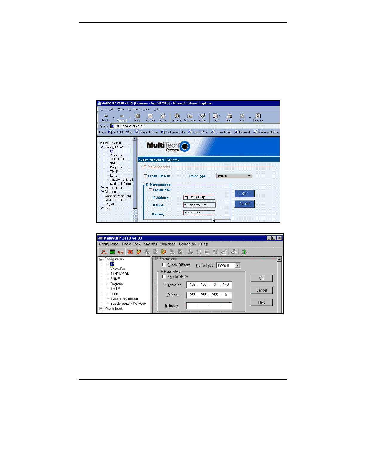
LOCAL CONFIGURATION........................................................................................ 122
Pre-Requisites................................................................................................... 122
IP Parameters..............................................................................................................122
T1 Telephony Parameters (for MVP2400 & MVP2410)............................................123
E1 Telephony Parameters (for MVP3010) .................................................................124
SMTP Parameters (for email call log reporting).........................................................125
Local Configuration Procedure (Summary) ..................................................... 126
Local Configuration Procedure (Detailed).......................................................127
Modem Relay ....................................................................................................144
CHAPTER 6: TECHNICAL CONFIGURATION FOR ANALOG/BRI
MULTIVOIPS (MVP130, MVP-210/210G, MVP-410/410G, MVP-810/810G &
MVP-410ST/810ST)................................................................................................ 195
C
ONFIGURING THE ANALOG/BRI MULTIVOIP .....................................................196
L
OCAL CONFIGURATION........................................................................................ 199
Pre-Requisites................................................................................................... 199
IP Parameters..............................................................................................................199
4
Page 5

MultiVOIP User Guide Contents MultiMVP
3
Analog Telephony Interface Parameters (for MVP130/210/410/810).......................200
ISDN-BRI Telephony Parameters (for MVP-410ST/810ST).....................................201
SMTP Parameters (for email call log reporting).........................................................202
Local Configuration Procedure (Summary) ..................................................... 203
Local Configuration Procedure (Detailed).......................................................204
Modem Relay ....................................................................................................221
CHAPTER 7: T1 PHONEBOOK CONFIGURATION ......................................277
C
ONFIGURING THE MVP2400/2410 MULTIVOIP PHONEBOOKS.......................... 278
T1 P
HONEBOOK EXAMPLES................................................................................... 301
3 Sites, All-T1 Example..................................................................................... 301
Configuring Mixed Digital/Analog VOIP Systems ...........................................307
Call Completion Summaries .............................................................................316
Variations in PBX Characteristics....................................................................319
CHAPTER 8: E1 PHONEBOOK CONFIGURATION ......................................320
MVP3010 I
NBOUND AND OUTBOUND MULTIVOIP PHONEBOOKS .......................321
Free Calls: One VOIP Site to Another.............................................................322
Local Rate Calls: Within Local Calling Area of Remote VOIP....................... 323
National Rate Calls: Within Nation of Remote VOIP Site...............................325
Inbound versus Outbound Phonebooks.............................................................326
P
HONEBOOK CONFIGURATION PROCEDURE........................................................... 330
E1 P
HONEBOOK EXAMPLES................................................................................... 349
3 Sites, All-E1 Example ....................................................................................349
Configuring Digital & Analog VOIPs in Same System..................................... 356
Call Completion Summaries.......................................................................................365
Variations in PBX Characteristics....................................................................368
International Telephony Numbering Plan Resources....................................... 369
CHAPTER 9: ANALOG/BRI PHONEBOOK CONFIGURATION ................. 371
CHAPTER 10: OPERATION AND MAINTENANCE ......................................373
O
PERATION AND MAINTENANCE ........................................................................... 374
System Information screen................................................................................ 374
Statistics Screens ..............................................................................................376
About Call Progress..........................................................................................376
About Logs........................................................................................................ 382
About Reports ...................................................................................................385
About IP Statistics............................................................................................. 386
About Packetization Time .................................................................................390
About T1/E1 and BRI Statistics.........................................................................393
About Registered Gateway Details ................................................................... 405
M
ULTIVOIP PROGRAM MENU ITEMS .....................................................................407
Date and Time Setup......................................................................................... 409
Obtaining Updated Firmware...........................................................................409
Implementing a Software Upgrade ................................................................... 413
Identifying Current Firmware Version .......................................................................413
Downloading Firmware..............................................................................................414
Downloading CAS Protocols......................................................................................417
5
Page 6

Contents MultiVOIP User Guide
Downloading Factory Defaults...................................................................................419
Setting and Downloading User Defaults ..........................................................421
Downloading IFM Firmware............................................................................423
Setting a Password (Windows GUI) ................................................................. 424
Setting a Password (Web Browser GUI) .......................................................... 427
Un-Installing the MultiVOIP Software .............................................................428
Upgrading Software..........................................................................................430
FTP S
ERVER FILE TRANSFERS (“DOWNLOADS”) ..................................................431
W
EB BROWSER INTERFACE ...................................................................................441
S
YSLOG SERVER FUNCTIONS ................................................................................ 446
CHAPTER 11: EMBEDDED GATEKEEPER (FOR MVP-210G/410G/810G)
..................................................................................................................................449
I
NTRODUCTION TO EMBEDDED GATEKEEPER ........................................................450
GETTING STARTED WITH THE GATEKEEPER-EQUIPPED MULTIVOIP .................... 451
EMBEDDED GATEKEEPER SYSTEM EXAMPLE ........................................................454
G
ATEKEEPER BASICS............................................................................................. 481
Introduction ......................................................................................................481
Mandatory Gatekeeper Functions .................................................................... 481
Address Translation....................................................................................................481
Admission Control......................................................................................................481
Bandwidth Control .....................................................................................................481
Zone Management......................................................................................................482
Optional Gatekeeper Functions........................................................................482
Call Control Signaling................................................................................................482
Call Authorization ......................................................................................................482
Bandwidth Management.............................................................................................482
Call Management .......................................................................................................483
FEATURES.............................................................................................................. 483
T
HE GATEKEEPER PROTOCOLS..............................................................................484
MULTIVOIP GATEKEEPER SOFTWARE SCREENS................................................... 487
GK DEFINED SERVICE TYPES................................................................................516
Example of a Gatekeeper Service .....................................................................516
Built-in Gatekeeper-Defined Services............................................................... 517
Service Types: Zone Prefixes (1 and 2)......................................................................517
Service Types: Forward..............................................................................................519
GATEKEEPER LOG DATA DATA FILES ................................................................... 520
G
ATEKEEPER SOFTWARE USER LICENSE AGREEMENT ......................................... 521
CHAPTER 12 WARRANTY, SERVICE, AND TECH SUPPORT................... 523
IMITED WARRANTY.............................................................................................524
L
R
EPAIR PROCEDURES FOR U.S. AND CANADIAN CUSTOMERS ...............................524
ECHNICAL SUPPORT ............................................................................................ 526
T
Contacting Technical Support ..........................................................................526
CHAPTER 13: REGULATORY INFORMATION ............................................527
EMC, Safety, and R&TTE Directive Compliance.............................................528
FCC D
ECLARATION .............................................................................................. 528
Industry Canada ...............................................................................................529
6
Page 7

MultiVOIP User Guide Contents MultiMVP
3
FCC Part 68 Telecom....................................................................................... 529
Canadian Limitations Notice ............................................................................ 530
APPENDIX A: EXPANSION CARD INSTALLATION (MVP24-48 & MVP30-
60).............................................................................................................................531
I
NSTALLATION.......................................................................................................532
OPERATION............................................................................................................ 534
APPENDIX B: CABLE PINOUTS ...................................................................... 535
A
PPENDIX B: CABLE PINOUTS..............................................................................536
Command Cable ...............................................................................................536
Ethernet Connector........................................................................................... 536
T1/E1 Connector............................................................................................... 537
Voice/Fax Channel Connectors ........................................................................ 537
ISDN BRI RJ-45 Pinout Information ................................................................ 539
ISDN Interfaces: “ST” and “U” .....................................................................540
APPENDIX C: TCP/UDP PORT ASSIGNMENTS ...........................................541
W
ELL KNOWN PORT NUMBERS ............................................................................. 542
PORT NUMBER ASSIGNMENT LIST ......................................................................... 542
APPENDIX D: INSTALLATION INSTRUCTIONS FOR MVP428 UPGRADE
CARD....................................................................................................................... 543
I
NSTALLATION INSTRUCTIONS FOR MVP428 UPGRADE CARD .............................. 544
APPENDIX E: CALL STATES & REASONS FOR EMBEDDED
GATEKEEPERS ....................................................................................................548
C
ALL STATES AND CALL REASONS ....................................................................... 549
Possible Call States of which the Embedded Gatekeeper Software can be notified
..........................................................................................................................549
Call Reasons sent to Embedded Gatekeeper Software with respect to a Call
State. ................................................................................................................. 552
INDEX ..................................................................................................................... 556
7
Page 8

Chapter 1: Overview
8
Page 9

MultiVOIP User Guide Overview
About This Manual
This manual is about Voice-over-IP products made by Multi-Tech Systems,
Inc. It describes four product groups.
1. T1 Digital MultiVOIP units, models MVP2400, MVP2410, and the
capacity-doubling add-on expansion card, model MVP24-48 (which
fits the MVP2410 only).
2. E1 Digital MultiVOIP units, models, MVP3010 and the capacitydoubling add-on expansion card, model MVP30-60.
3. Analog MultiVOIP units,
models MVP810, MVP410, MVP210, & MVP130 and
models MVP810G, MVP410G, & MVP210G with embedded
gatekeeper function.
4. ISDN-BRI MultiVOIP units, models MVP410ST & MVP810ST.
The table below describes the vital characteristics of these various models.
9
Page 10
Overview MultiVOIP User Guide
MultiVOIP Product Family
Description
Model
MVP
2400
Function T1
digital
VOIP
unit
Capacity 24
channels24channels24added
Chassis/
Mounting
Description
Model
Table
top
MVP
810 (G)
Function analog
voip
Capacity 8
channels
Chassis/
Mounting
19” 1U
rack
mount
MVP-
2410
T1
digital
VOIP
unit
19” 1U
rack
mount
MVP
428 (G)
add-on
card
4 added
channels4channels2channels
circuit
card
only
MVP
24-48
T1
digital
VOIP
add-on
card
channels
circuit
card
only
MVP
410 (G)
analog
voip
19” 1U
rack
mount
MVP
3010
E1
digital
VOIP
unit
30
channels30added
19” 1U
rack
mount
MVP
210 (G)
Analog
voip
Table
top
MVP
30-60
E1
digital
VOIP
add-on
card
channels
circuit
card
only
MVP
130
Analog
voip
1
channel
table
top
Description
Model
MVP810ST MVP410ST
Function ISDN-BRI voip ISDN-BRI voip
Capacity 4 ISDN lines
(8 B-channels)
Chassis/
19” 1U rack mount 19” 1U rack mount
2 ISDN lines
(4 B-channels)
Mounting
1. “G” models have embedded Gatekeeper.
2. “BRI” means Basic Rate Interface.
10
Page 11

MultiVOIP User Guide Overview
How to Use This Manual. In short, use the index and the examples.
When our readers crack open this large manual, they generally need one of two
things: information on a very specific software setting or technical parameter
(about telephony or IP) or they need help when setting up phonebooks for their
voip systems. The index gives quick access to voip settings and parameters.
It’s detailed. Use it. The best way to learn about phonebooks is to wade
through examples like those in our chapters on T1 (North American standard)
Phonebooks and E1 (Euro standard) Phonebooks. Also, the quick setup info of
the printed Quick Start Guide is replicated in this manual for your convenience.
Finally, this manual is meant to be comprehensive. If you notice that
something important is lacking, please let us know.
Additional Resources. The MultiTech web site (www.multitech.com) offers
both a list of Frequently Asked Questions (the MultiVOIP FAQ) and a
collection of resolutions of issues that MultiVOIP users have encountered
(these are Troubleshooting Resolutions in the searchable Knowledge Base).
Variable Model/Version Icon and Typography. The MultiVOIP product
family is a coordinated set of products that can operate with each other in a
seamless fashion. For example, both the digital and analog MultiVOIP units
use the same graphic user interface (GUI) in the MultiVOIP configuration
software and both operate under a single GUI in the MultiVoipManager remote
management software. Because this is the case, the various model numbers and
version numbers of MultiVOIP family products will each appear in various
dialog boxes and commands. But instead of showing these dialog boxes once
for each model in this manual, we substitute the following icon.
Figure 1-1: Variable Model/Version Icon
It indicates that, whatever MultiVOIP model you are using, all details except
the very model and version numbers themselves will be the same regardless of
the MultiVOIP model used. Also, in some cases, we will use other
typographic devices, like blank underlining
(“MultiVOIP ____”) to denote information that applies to any
and all of the products in this product family.
11
Page 12

Overview MultiVOIP User Guide
Introduction to TI MultiVOIPs (MVP2400, MVP2410, & MVP24-48)
We proudly present MultiTech’s T1 Digital Multi-VOIP products.
The MVP2400 is a tabletop model; the MVP2410 is a rack-mount model; and
the MVP24-48 is an add-on expansion card that doubles the capacity of the
MVP2410 without adding another chassis. All of these voice-over-IP products
have fax capabilities. All of these models adhere to the North American
standard of T1 trunk telephony using digital 24-channel time-division
multiplexing, which allows 24 phone conversations to occur on the T1 line
simultaneously. All can also accommodate T1 lines of the ISDN Primary Rate
Interface type (ISDN-PRI).
Scale-ability. The MVP2400 and MVP2410 are tailored to companies needing
more than a few voice-over-IP lines, but not needing carrier-class equipment.
When expansion is needed, the MVP2410 can be field-upgraded into a dual T1
unit by installing the MVP24-48 kit, which is essentially a second MultiVOIP
motherboard that fits in an open expansion-card slot in the MVP2410. The
upgraded dual unit then accommodates two T1 lines.
T1 VOIP Traffic. The MVP-2400/2410 accepts its outbound traffic from a T1
trunk that’s connected to either a PBX or to a telco/carrier. The MVP2400/2410 transforms the telephony signals into IP packets for transmission on
LANs, WANs, or the Internet. Inbound IP data traffic is converted to
telephony data and signaling.
When connected to PBX. When connected to a PBX, the MVP-2400/2410
creates a network node served by 10/100-Base T connections. Local PBX
phone extensions gain toll-free access to all phone stations directly connected
to the VOIP network. Phone extensions at any VOIP location also gain tollfree access to the entire local public-switched telephone network (PSTN) at
every other VOIP location in the system.
When connected to PSTN. When the T1 line(s) connected to the MVP2400/2410 are connected directly to the PSTN, the unit becomes a Point-ofPresence server dedicated to local calls off-net.
12
Page 13

MultiVOIP User Guide Overview
H.323, SIP & SPP. Being H.323 compatible, the MVP-2400/2410 can place
calls to telephone equipment at remote IP network locations that also contain
H.323 compatible voice-over-IP gateways. It will interface with H.323
software and H.323 gatekeeper units. H.323 specifications also bring to voip
telephony many special features common to conventional telephony. H.323
features of this kind that have been implemented into the MultiVOIP include
Call Hold, Call Waiting, Call Name Identification, Call Forwarding (from the
H.450 standard), and Call Transfer (H.450.2 from H.323 Version 2). The
fourth version of the H.323 standard improves system resource usage (esp.
logical port or socket usage) by handling call signaling more compactly and
allowing use of the low-overhead UDP protocol instead of the error-correcting
TCP protocol where possible.
The MultiVOIP is also SIP-compatible. (“SIP” means Session Initiation
Protocol.) However, H.450 Supplementary Services features can be used under
H.323 only and not under SIP.
SPP (Single-Port Protocol) is a non-standard protocol developed by MultiTech. SPP is not compatible with the “Proprietary” protocol used in MultiTech’s earlier generation of voip gateways. SPP offers advantages in certain
situations, especially when firewalls are used and when dynamic IP address
assignment is needed. However, when SPP is used, certain features of SIP and
H.323 will not be available and SPP will not inter-operate with voip systems
using H.323 or SIP.
Data Compression & Quality of Service. The MultiVOIP2400/2410 comes
equipped with a variety of data compression capabilities, including G.723,
G.729, and G.711 and features DiffServ quality-of-service (QoS) capabilities.
VOIP Functions. The MultiVOIP MVP-2400/2410 gateway performs four
basic functions: (a) it converts a dialed number into an IP address, (b) it sends
voice over the data network, (c) it establishes a connection with another VOIP
gateway at a remote site, and (d) it receives voice over the data network. Voice
is handled as IP packets with a variety of compression options. Each T1
connection to the MultiVOIP provides 24 time-slot channels to connect to the
telco or to serve phone or fax stations connected to a PBX.
Ports. The MVP2400 and MVP2410 each have one 10/100 Mbps Ethernet
LAN interface and one Command port for configuration. An MVP2410
upgraded with the MVP24-48 kit will have two Ethernet LAN interfaces and
two Command ports.
PSTN Failover Feature. The MultiVOIP can be programmed to divert calls
to the PSTN temporarily in case the IP network fails.
Gatekeeper. T1 voip systems can have gatekeeper functionality either by
adding, as an endpoint, either a Multi-Tech standalone gatekeeper (special
software residing in separate hardware), or an analog gateway with embedded
gatekeeper functionality (MVP210G, MVP410G, or MVP810G). Gatekeepers
are optional but useful within voip systems. The gatekeeper acts as the
13
Page 14

Overview MultiVOIP User Guide
‘clearinghouse’ for all calls within its zone. MultiTech’s embedded and standalone gatekeeper software packages both perform all of the standard
gatekeepers functions (address translation, admission control, bandwidth
control, and zone management) and also support many valuable optional
functions (call control signaling, call authorization, bandwidth management,
and call management). The stand-alone gatekeeper is, however, slightly more
feature-rich than the embedded gatekeeper. For more details, see the
“Embedded Gatekeeper” chapter of this manual and the manual on
MultiTech’s stand-alone gatekeeper.
Management. Configuration and system management can be done locally
with the MultiVOIP configuration software. After an IP address has been
assigned locally, other configuration can be done remotely using the
MultiVOIP web browser GUI. Remote system management can be done with
the MultiVoipManager SNMP software or via the MultiVOIP web browser
GUI. All of these control software packages are included on the Product CD.
14
Page 15

MultiVOIP User Guide Overview
While the web GUI’s appearance differs slightly, its content and organization
are essentially the same as that of the Windows GUI (except for logging).
The primary advantage of the web GUI is remote access for control and
configuration. The controller PC and the MultiVOIP unit itself must both be
connected to the same IP network and their IP addresses must be known.
Once you’ve begun using the web browser GUI, you can go back to the
MultiVOIP Windows GUI at any time. However, you must log out of the web
browser GUI before using the MultiVOIP Windows GUI.
15
Page 16

Overview MultiVOIP User Guide
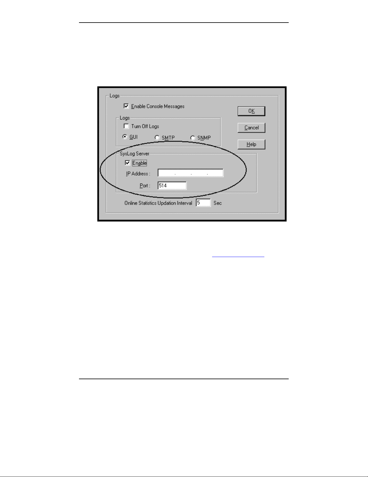
Logging of System Events. MultiTech has built SysLog Server functionality
into the software of the MultiVOIP units. SysLog is a de facto standard for
logging events in network communication systems.
The SysLog Server resides in the MultiVOIP unit itself. To implement this
functionality, you will need a SysLog client program (sometimes referred to as
a “daemon”). SysLog client programs, both paid and freeware, can be obtained
from Kiwi Enterprises, among other firms. See www.kiwisyslog.com. SysLog
client programs essentially give you a means of structuring console messages
for convenience and ease of use.
MultiTech Systems does not endorse any particular SysLog client program.
SysLog client programs by any qualified provider should suffice for use with
MultiVOIP units. Kiwi’s brief description of their SysLog program indicates
the typical scope of such programs. “Kiwi Syslog Daemon is a freeware
Syslog Daemon for the Windows platform. It receives, logs, displays and
forwards Syslog messages from hosts such as routers, switches, Unix hosts and
any other syslog enabled device. There are many customizable options
available.”
16
Page 17
MultiVOIP User Guide Overview
Supplementary Telephony Services. The H.450 standard (an addition to
H.323) brings to voip telephony more of the premium features found in PSTN
and PBX telephony. MultiVOIP units offer five of these H.450 features: Call
Transfer, Call Hold, Call Waiting, Call Name Identification (not the same as
Caller ID), and Call Forwarding. (The first four features are found in the
“Supplementary Services” window; the fifth, Call Forwarding, appears in the
Add/Edit Inbound phonebook screen.) Note that the first three features are
closely related. All of these H.450 features are supported for H.323 operation
only; they are not supported for SIP or SPP.
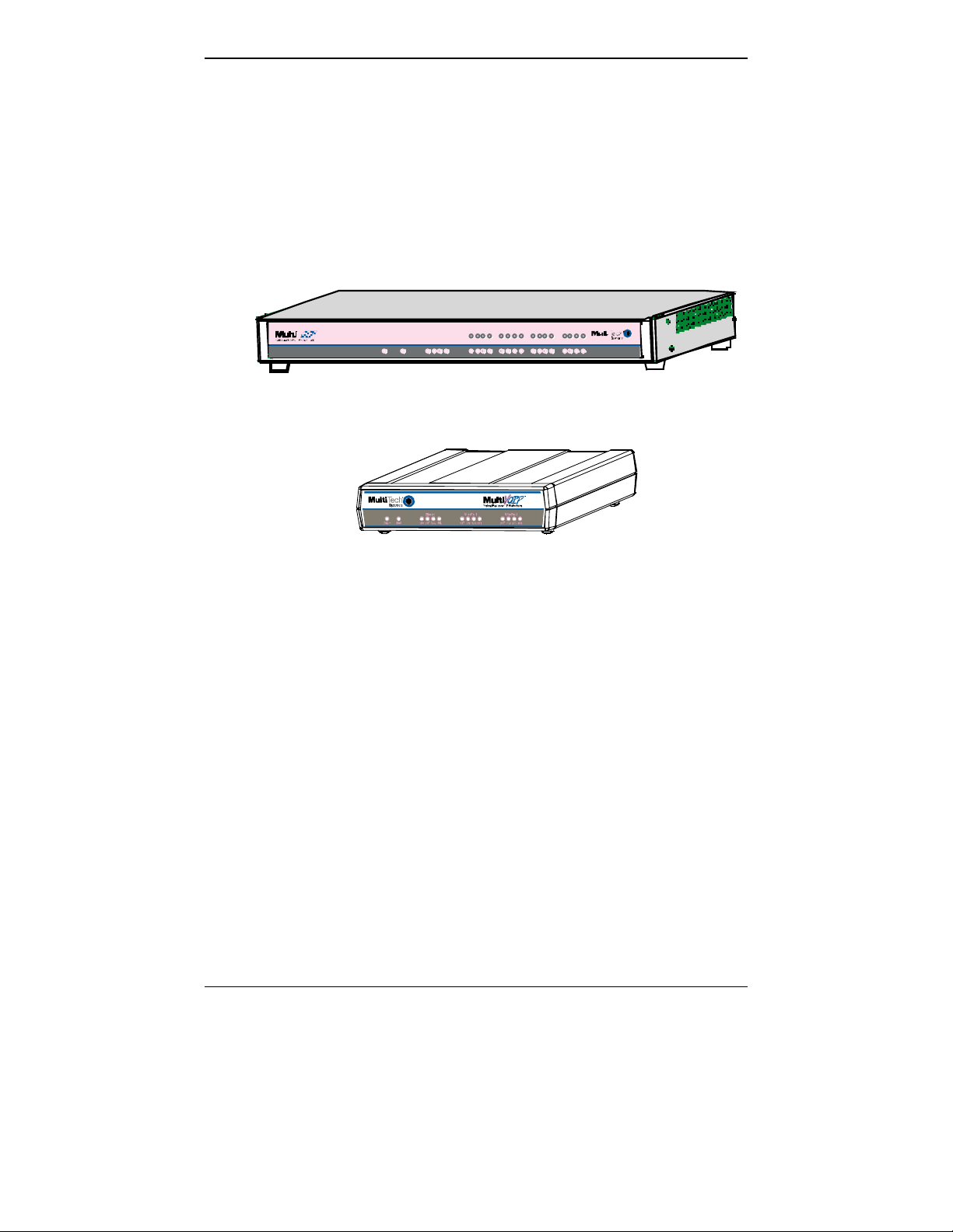
T1 Front Panel LEDs
The MVP2400, MVP2410, and MVP24-48 all use a common main circuit
board or motherboard. Consequently the LED indicators are the same for all.
Figure 1-2. MultiVOIP MVP2400 Front Panel
Active LEDs. The MVP2410 front panel has two sets of identical LEDs. In
the MVP2410 as shipped (that is, without an expansion card), the left-hand set
of LEDs is functional whereas the right-hand set is not.
When the MVP2410 has been upgraded with an MVP24-48 kit, the right-hand
set of LEDs will also become active.
Figure 1-3. MultiVOIP MVP2410x Chassis
T1 LED Descriptions
The descriptions below apply to all digital T1 MultiVOIP units. The
MVP2410 has four sets of LEDs plus a lone LED at its far right end. As
viewed from the front of the MVP2410, it is the two left groups that are active
and present feedback about the operation of the unit. If an MVP24-48
expansion card is added to the MVP2410, the two LED groups on the right
become operational with respect to the second T1 connection.
17
Page 18

Overview MultiVOIP User Guide
MVP2400/2410 Front Panel LED Definitions
LED NAME DESCRIPTION
Power Indicates presence of power.
Boot
After power up, the Boot LED will be on for about 10
seconds while the MVP2400/2410 is booting.
RCV Receive. Lights when receiving data on Ethernet port.
XMT Transmit. Lights when transmitting data on Ethernet
port.
LNK Link. When lit, VOIP “sees” the hub or network via
the Ethernet connection.
COL Collision. Lit when data collisions occur.
T1 When lit, indicates presence of T1 connection.
E1 E1. Not supported.
PRI PRI. On if T1 line is of ISDN-Primary-Rate type.
ONL Online. This LED is on when frame synchroni-zation
has been established on the T1/E1 link.
IC IC LED is on when Internal Clocking is selected in
T1/E1 configuration.
LC Indicates Loss of Carrier.
LS Indicates Loss of Signal.
Test For testing purposes only.
18
Page 19

MultiVOIP User Guide Overview
Introduction to EI MultiVOIPs (MVP3010 & MVP30-60)
We proudly present MultiTech’s E1 Digital Multi-VOIP products. The
MVP3010 is a rack-mount model and the MVP30-60 is an add-on expansion
card that doubles the capacity of the MVP3010 without adding another chassis.
All of these voice-over-IP products have fax capabilities. All adhere to the
European standard of E1 trunk telephony using digital 30-channel timedivision multiplexing, which allows 30 phone conversations to occur on the E1
line simultaneously. All can also accommodate E1 lines of the ISDN Primary
Rate Interface type (ISDN-PRI).
Scale-ability. The MVP3010 is tailored to companies needing more than a
few voice-over-IP lines, but not needing carrier-class equipment. When
expansion is needed, the MVP3010 can be field-upgraded into a dual E1 unit
by installing the MVP30-60 kit, which is essentially a second MultiVOIP
motherboard that fits into an open expansion-card slot in the MVP3010. The
upgraded dual unit then accommodates two E1 lines.
E1 VOIP Traffic. The MVP3010 accepts its outbound traffic from an E1
trunk that’s connected to either a PBX or to a telco/carrier. The MVP3010
transforms the telephony signals into IP packets for transmission on LANs,
WANs, or the Internet. Inbound IP data traffic is converted to telephony data
and signaling.
When connected to PBX. When connected to a PBX, the MVP3010 creates a
network node served by 10/100-Base T connections. Local PBX phone
extensions gain toll-free access to all phone stations directly connected to the
VOIP network. Phone extensions at any VOIP location also gain local-rate
access to the entire local public-switched telephone network (PSTN) at every
other VOIP location in the system.
When connected to PSTN. When the E1 line(s) connected to the MVP3010
are connected directly to the PSTN, the unit becomes a Point-of-Presence
server dedicated to local calls off-net.
19
Page 20

Overview MultiVOIP User Guide
H. 323, SIP, & SPP. Being H.323 compatible, the MVP3010 can place calls
to telephone equipment at remote IP network locations that also contain H.323
compatible voice-over-IP gateways. It will interface with H.323 software and
H.323 gatekeeper units. H.323 specifications also bring to voip telephony
many special features common to conventional telephony. H.323 features of
this kind that have been implemented into the MultiVOIP include Call Hold,
Call Waiting, Call Identification, Call Forwarding (from the H.450 standard),
and Call Transfer (H.450.2 from H.323 Version 2). The fourth version of the
H.323 standard improves system resource usage (esp. logical port or socket
usage) by handling call signaling more compactly and allowing use of the lowoverhead UDP protocol instead of the error-correcting TCP protocol where
possible.
The MultiVOIP is also SIP-compatible. (“SIP” means Session Initiation
Protocol.) However, H.450 Supplementary Services features can be used
under H.323 only and not under SIP.
SPP (Single-Port Protocol) is a non-standard protocol developed by MultiTech. SPP is not compatible with the “Proprietary” protocol used in MultiTech’s earlier generation of voip gateways. SPP offers advantages in certain
situations, especially when firewalls are used and when dynamic IP address
assignment is needed. However, when SPP is used, certain features of SIP and
H.323 will not be available and SPP will not inter-operate with voip systems
using H.323 or SIP.
Data Compression & Quality of Service. The MultiVOIP3010 comes
equipped with a variety of data compression capabilities, including G.723,
G.729, and G.711 and features DiffServ quality-of-service (QoS) capabilities.
VOIP Functions. The MultiVOIP MVP3010 gateway performs four basic
functions: (a) it converts a dialed number into an IP address, (b) it sends voice
over the data network, (c) it establishes a connection with another VOIP
gateway at a remote site, and (d) it receives voice over the data network. Voice
is handled as IP packets with a variety of compression options. Each E1
connection to the MultiVOIP provides 30 time-slot channels to connect to the
telco or to serve phone or fax stations connected to a PBX.
Ports. The MVP3010 also has a 10/100 Mbps Ethernet LAN interface, and a
Command port for configuration. An MVP3010 upgraded with the MVP30-60
kit will have two Ethernet LAN interfaces and two Command ports.
PSTN Failover Feature. The MultiVOIP can be programmed to divert calls
to the PSTN temporarily in case the IP network fails.
20
Page 21

MultiVOIP User Guide Overview
Gatekeeper. E1 voip systems can have gatekeeper functionality either by
adding, as an endpoint, either a Multi-Tech standalone gatekeeper (special
software residing in separate hardware) or an analog gateway with embedded
gatekeeper functionality (MVP210G, MVP410G, or MVP810G). Gatekeepers
are optional but useful within voip systems. The gatekeeper acts as the
‘clearinghouse’ for all calls within its zone. MultiTech’s embedded and standalone gatekeeper software packages both perform all of the standard
gatekeepers functions (address translation, admission control, bandwidth
control, and zone management) and also support many valuable optional
functions (call control signaling, call authorization, bandwidth management,
and call management). The stand-alone gatekeeper is, however, slightly more
feature-rich than the embedded gatekeeper. For more details, see the
“Embedded Gatekeeper” chapter of this manual and the manual on
MultiTech’s stand-alone gatekeeper.
Management. Configuration and system management can be done locally
with the MultiVOIP configuration software. After an IP address has been
assigned locally, other configuration can be done remotely using the
MultiVOIP web browser GUI. Remote system management can be done with
the MultiVoipManager SNMP software or via the MultiVOIP web browser
GUI. All of these control software packages are included on the Product CD.
21
Page 22

Overview MultiVOIP User Guide
While the web GUI’s appearance differs slightly, its content and organization
are essentially the same as that of the Windows GUI (except for logging).
The primary advantage of the web GUI is remote access for control and
configuration. The controller PC and the MultiVOIP unit itself must both be
connected to the same IP network and their IP addresses must be known.
Once you’ve begun using the web browser GUI, you can go back to the
MultiVOIP Windows GUI at any time. However, you must log out of the web
browser GUI before using the MultiVOIP Windows GUI.
22
Page 23
MultiVOIP User Guide Overview
Logging of System Events. MultiTech has built SysLog Server functionality
into the software of the MultiVOIP units. SysLog is a de facto standard for
logging events in network communication systems.
The SysLog Server resides in the MultiVOIP unit itself. To implement this
functionality, you will need a SysLog client program (sometimes referred to as
a “daemon”). SysLog client programs, both paid and freeware, can be obtained
from Kiwi Enterprises, among other firms. See www.kiwisyslog.com. SysLog
client programs essentially give you a means of structuring console messages
for convenience and ease of use.
MultiTech Systems does not endorse any particular SysLog client program.
SysLog client programs by any qualified provider should suffice for use with
MultiVOIP units. Kiwi’s brief description of their SysLog program indicates
the typical scope of such programs. “Kiwi Syslog Daemon is a freeware
Syslog Daemon for the Windows platform. It receives, logs, displays and
forwards Syslog messages from hosts such as routers, switches, Unix hosts and
any other syslog enabled device. There are many customizable options
available.”
23
Page 24
Overview MultiVOIP User Guide
Supplementary Telephony Services. The H.450 standard (an addition to
H.323) brings to voip telephony more of the premium features found in PSTN
and PBX telephony. MultiVOIP units offer five of these H.450 features: Call
Transfer, Call Hold, Call Waiting, Call Name Identification (not the same as
Caller ID), and Call Forwarding. (The first four features are found in the
“Supplementary Services” window; the fifth, Call Forwarding, appears in the
Add/Edit Inbound phonebook screen.) Note that the first three features are
closely related. All of these H.450 features are supported for H.323 operation
only; they are not supported for SIP or SPP.
E1 Front Panel LEDs
Because the MVP3010 and MVP30-60 both use a common main circuit card or
motherboard, the LED indicators are the same for both.
Figure 1-4. MultiVOIP MVP3010 Chassis
Active LEDs. The MVP3010 front panel has two sets of identical LEDs. In
the MVP3010 as shipped (that is, without an expansion card), the left-hand set
of LEDs is functional whereas the right-hand set is not.
When the MVP3010 has been upgraded with an MVP30-60 kit, the right-hand
set of LEDs will also become active.
24
Page 25

MultiVOIP User Guide Overview
E1 LED Descriptions
MVP3010 Front Panel LED Definitions
LED NAME DESCRIPTION
Power Indicates presence of power.
Boot
RCV Receive. Lights when receiving data on Ethernet port.
XMT Transmit. Lights when transmitting data on Ethernet
LNK Link. When lit, VOIP “sees” the hub or network via
COL Collision. Lit when data collisions occur.
T1 T1. Not supported.
E1 E1. When lit, indicates presence of E1 connection.
PRI PRI. On if E1 line is of ISDN-Primary-Rate type.
ONL Online. This LED is on when frame synchronization
IC IC LED is on when Internal Clocking is selected in
LC Indicates Loss of Carrier.
LS Indicates Loss of Signal.
Test For testing purposes only. For testing purposes only.
After power up, the Boot LED will be on for about 10
seconds while the MVP3010 is booting.
port.
the Ethernet connection.
has been established on the T1/E1 link.
T1/E1 configuration.
25
Page 26

Overview MultiVOIP User Guide
Introduction to Analog MultiVOIPs (MVP130, MVP-210/410/810 & MVP428)
VOIP: The Free Ride. We proudly present Multi-Tech's MVP130, MVP210/410/810 generation of MultiVOIP Voice-over-IP Gateways and models
MVP-210G/410G/810G equipped with embedded gatekeeper functionality .
All of these models allow voice/fax communication to be transmitted at no
additional expense over your existing IP network, which has ordinarily been
data only. To access this free voice and fax communication, you simply
connect the MultiVOIP to your telephone equipment and your existing Internet
connection. These analog MultiVOIPs inter-operate readily with T1 or E1
MultiVOIP units.
Capacity. MultiVOIP models MVP810 and MVP810G are eight-channel
units, models MVP410 and MVP410G are four-channel units, and models
MVP210 and MVP210G are two-channel units. The MVP130 is a singlechannel unit. All of these MultiVOIP units have a 10/100Mbps Ethernet
interface and a command port for configuration. The MVP428 is an expansion
circuit card for the four-channel MVP410 that turns it into an eight-channel
voip.
Mounting. Mechanically, the MVP410 and MVP810 MultiVOIPs are
designed for a one-high industry-standard EIA 19-inch rack enclosure. By
contrast, MVP130 and the MVP210 are tabletop units. The product must be
installed by qualified service personnel in a restricted-access area, in
accordance with Articles 110-16, 10-17, and 110-18 of the National Electrical
Code, ANSI/NFPA 70.
Phone System Transparency. These MultiVOIPs inter-operate with a
telephone switch or PBX, acting as a switching device that directs voice and
fax calls over an IP network. The MultiVOIPs have “phonebooks,” directories
that determine to who calls may be made and the sequences that must be used
to complete calls through the MultiVOIP. The phonebooks allow the phone
user to interact with the VOIP system just as they would with an ordinary PBX
or telco switch. When the phonebooks are set, special dialing sequences are
minimized or eliminated altogether. Once the call destination is determined,
the phonebook settings determine whether the destination VOIP unit must strip
off or add dialing digits to make the call appear at its destination to be a local
call.
H. 323, SIP, & SPP. Being H.323 compatible, the analog MultiVOIP unit can
place calls to telephone equipment at remote IP network locations that also
contain H.323 compatible voice-over-IP gateways. It will interface with H.323
software and H.323 gatekeeper units. H.323 specifications also bring to voip
telephony many special features common to conventional telephony. H.323
features of this kind that have been implemented into the MultiVOIP include
Call Hold, Call Waiting, Call Identification, Call Forwarding (from the H.450
26
Page 27

MultiVOIP User Guide Overview
standard), and Call Transfer (H.450.2 from H.323 Version 2). The fourth
version of the H.323 standard improves system resource usage (esp. logical
port or socket usage) by handling call signaling more compactly and allowing
use of the low-overhead UDP protocol instead of the error-correcting TCP
protocol where possible.
The MultiVOIP is also SIP-compatible. (“SIP” means Session Initiation
Protocol.) However, H.450 Supplementary Services features can be used
under H.323 only and not under SIP.
SPP (Single-Port Protocol) is a non-standard protocol developed by MultiTech. SPP is not compatible with the “Proprietary” protocol used in MultiTech’s earlier generation of voip gateways. SPP offers advantages in certain
situations, especially when firewalls are used and when dynamic IP address
assignment is needed. However, when SPP is used, certain features of SIP and
H.323 will not be available and SPP will not inter-operate with voip systems
using H.323 or SIP.
Data Compression & Quality of Service. The analog MultiVOIP unit comes
equipped with a variety of data compression capabilities, including G.723,
G.729, and G.711 and features DiffServ quality-of-service (QoS) capabilities.
PSTN Failover Feature. The MultiVOIP can be programmed to divert calls
to the PSTN temporarily in case the IP network fails.
Gatekeepers. For voip systems built with MultiTech’s analog gateway units,
users can have either an embedded gatekeeper (built into an MVP210G,
MVP410G, or MVP810G) or a stand-alone gatekeeper (gatekeeper software
residing in separate hardware). Gatekeepers are optional but useful within voip
systems. The gatekeeper acts as the ‘clearinghouse’ for all calls within its
zone. MultiTech’s embedded and stand-alone gatekeeper software packages
both perform all of the standard gatekeepers functions (address translation,
admission control, bandwidth control, and zone management) and also support
many valuable optional functions (call control signaling, call authorization,
bandwidth management, and call management). The stand-alone gatekeeper is,
however, slightly more feature-rich than the embedded gatekeeper. For more
details, see the “Embedded Gatekeeper” chapter of this manual and the manual
on MultiTech’s stand-alone gatekeeper.
27
Page 28
Overview MultiVOIP User Guide
Management. Configuration and system management can be done locally
with the MultiVOIP configuration software. After an IP address has been
assigned locally, other configuration can be done remotely using the
MultiVOIP web browser GUI. Remote system management can be done with
the MultiVoipManager SNMP software or via the MultiVOIP web browser
GUI. All of these control software packages are included on the Product CD.
While the web GUI’s appearance differs slightly, its content and organization
are essentially the same as that of the Windows GUI (except for logging).
The primary advantage of the web GUI is remote access for control and
configuration. The controller PC and the MultiVOIP unit itself must both be
connected to the same IP network and their IP addresses must be known.
28
Page 29
MultiVOIP User Guide Overview
Once you’ve begun using the web browser GUI, you can go back to the
MultiVOIP Windows GUI at any time. However, you must log out of the web
browser GUI before using the MultiVOIP Windows GUI.
Logging of System Events. MultiTech has built SysLog Server functionality
into the software of the MultiVOIP units. SysLog is a de facto standard for
logging events in network communication systems.
The SysLog Server resides in the MultiVOIP unit itself. To implement this
functionality, you will need a SysLog client program (sometimes referred to as
a “daemon”). SysLog client programs, both paid and freeware, can be obtained
from Kiwi Enterprises, among other firms. See www.kiwisyslog.com. SysLog
client programs essentially give you a means of structuring console messages
for convenience and ease of use.
MultiTech Systems does not endorse any particular SysLog client program.
SysLog client programs by any qualified provider should suffice for use with
MultiVOIP units. Kiwi’s brief description of their SysLog program indicates
the typical scope of such programs. “Kiwi Syslog Daemon is a freeware
Syslog Daemon for the Windows platform. It receives, logs, displays and
forwards Syslog messages from hosts such as routers, switches, Unix hosts and
any other syslog enabled device. There are many customizable options
available.”
29
Page 30
Overview MultiVOIP User Guide
Supplementary Telephony Services. The H.450 standard (an addition to
H.323) brings to voip telephony more of the premium features found in PSTN
and PBX telephony. MultiVOIP units offer five of these H.450 features: Call
Transfer, Call Hold, Call Waiting, Call Name Identification (not the same as
Caller ID), and Call Forwarding. (The first four features are found in the
“Supplementary Services” window; the fifth, Call Forwarding, appears in the
Add/Edit Inbound phonebook screen.) Note that the first three features are
closely related. All of these H.450 features are supported for H.323 operation
only; they are not supported for SIP or SPP.
Power
XMT RCVXSG RSG XMTRCV XSG RSGXMT RCV XSGRSG
RCV XMT COLLNK XMTRCV XSG RSG
Voice/Fax 1 Voice/Fax 2Voice/Fax 3 Voice/Fax 4EthernetBoot
XMT RCVXSG RSG
XMT RCV XSGRSG
XMTRCV XSG RSG
XMTRCV XSG RSG
Voice/Fax 5 Voice/Fax 6Voice/Fax 7Voice/Fax 8
Figure 1-5: MVP-410/810 Chassis
Figure 1-6: MVP-210 Chassis
30
Page 31

MultiVOIP User Guide Overview
Figure 1-7. MultiVOIP MVP130Chassis
Analog MultiVOIP Front Panel LEDs
LED Types. The MultiVOIPs have two types of LEDs on their front panels:
(1) general operation LED indicators (for power, booting, and
ethernet functions), and
(2) channel operation LED indicators that describe the data traffic and
performance in each VOIP data channel.
Active LEDs. On both the MVP410 and MVP810, there are eight sets of
channel-operation LEDs. However, on the MVP410, only the lower four sets
of channel-operation LEDs are functional. On the MVP810, all eight sets are
functional.
Voice/Fax 5 Voice /Fa x 6 Voice/ Fax 7 Vo ice /Fax 8
Power
Ethernet
Boot
RCV XMT COL LNK
XMT RCV XSG RSG XMT RCV XSG RSG XMT RCV XSG RSG
Voice/F ax 1
Voice/F ax 2 Voice /Fa x 3
XMT RCV XSG RSG
XMT RCV XSG RSG
XMT RCV XSG RSG
XMT RCV XSG RSG
Voice /Fa x 4
XMT RCV XSG RSG
Figure 1-8. MVP410/810 Front Panel
31
Page 32

Overview MultiVOIP User Guide
Similarly, the MVP210 has the general-operation indicator LEDs and two sets
of channel-operation LEDs, one for each channel.
Figure 1-9. MVP210 Front Panel
Finally, the MVP130 has the general-operation indicator LEDs and a set of
channel-operation LEDs for its single voip channel.
Figure 1-10. MVP130 Front Panel
32
Page 33

MultiVOIP User Guide Overview
Analog MultiVOIP LED Descriptions
MVP210/410/810 Front Panel LED Definitions
LED NAME DESCRIPTION
General Operation LEDs (one set on each MultiVOIP model)
Power Indicates presence of power.
Boot
After power up, the Boot LED will be on briefly while the
MultiVOIP is booting. It lights whenever the MultiVOIP is
booting or downloading a setup configuration data set.
Ethernet RCV. Receive. Lights (blinks) when receiving data on
Ethernet port.
XMT. Transmit. Lights (blinks) when transmitting data on
Ethernet port. ..
LNK. Link. When lit, VOIP “sees” the hub or network via
the Ethernet connection. ..
COL. Collision. Lit when data collisions occur. ..
Channel-Operation LEDs (one set for each channel)
XMT
RCV
XSG
RSG
Transmit. This indicator blinks when voice packets are
being transmitted to the local area network.
Receive. This indicator blinks when voice packets are
being received from the local area network.
Transmit Signal. This indicator lights when the FXSconfigured channel is off-hook, the FXO-configured
channel is receiving a ring from the Telco, or the M lead is
active on the E&M configured channel. That is, it lights
when the MultiVOIP is receiving a ring from the PBX.
Receive Signal. This indicator lights when the FXSconfigured channel is ringing, the FXO-configured channel
has taken the line off-hook, or the E lead is active on the
E&M-configured channel.
33
Page 34

Overview MultiVOIP User Guide
MVP130 Front Panel LED Definitions
LED NAME DESCRIPTION
General Operation LEDs
Power Indicates presence of power.
Boot
Ethernet
After power up, the Boot LED will be on briefly while the
MultiVOIP is booting. It lights whenever the MultiVOIP is
booting or downloading a setup configuration data set.
SP. During normal operation, the SP LED lights to indicate
100Mbps is selected.
AC. During normal operation, the AC LED lights when
transmitting or receiving. It will flash at a rate of 50ms high
and 50ms low when active.
CL. During normal operation, the CL LED lights to indicate
a collision. It will flash at a rate of 50ms high and 50ms low
when active.
LK. During normal operation, the LK LED lights to
indicate a good link is detected.
Channel-Operation LEDs
TX
RX
XS
Transmit. This indicator blinks when voice packets are
being transmitted to the local area network.
Receive. This indicator blinks when voice packets are
being received from the local area network.
Transmit Signal. This indicator lights when the
FXS-configured channel is off-hook or the FXOconfigured channel is receiving a ring from the Telco
or PBX.
RS
Receive Signal. This indicator lights when the FXS-
configured channel is ringing or the FXO-configured
channel has taken the line off-hook.
34
Page 35

MultiVOIP User Guide Overview
Introduction to ISDN-BRI MultiVOIPs (MVP410ST & MVP810ST)
VOIP: The Free Ride. We proudly present Multi-Tech's MVP-410ST/810ST
generation of MultiVOIP Voice-over-IP Gateways. All of these models allow
voice/fax communication to be transmitted at no additional expense over your
existing IP network, which has ordinarily been data only. To access this free
voice and fax communication, you simply connect the MultiVOIP to your
telephone equipment and your existing Internet connection. These ISDN Basic
Rate Interface (ISDN-BRI) MultiVOIPs inter-operate readily with T1 or E1
MultiVOIP units (T1 and E1 MultiVOIP units can operate in ISDN Primary
Rate Mode, ISDN-PRI, as well).
Capacity. MultiVOIP model MVP810ST accommodates four ISDN-BRI lines
(eight B-channels) and model MVP410ST accommodates two ISDN-BRI
channels (four B-channels). Both of these MultiVOIP units have a 10/100Mbps
Ethernet interface and a command port for configuration.
Mounting. Mechanically, the MVP410ST and MVP810ST MultiVOIPs are
designed for a one-high industry-standard EIA 19-inch rack enclosure. The
product must be installed by qualified service personnel in a restricted-access
area, in accordance with Articles 110-16, 10-17, and 110-18 of the National
Electrical Code, ANSI/NFPA 70.
Phone System Transparency. These MultiVOIPs inter-operate with a
telephone switch or PBX, acting as a switching device that directs voice and
fax calls over an IP network. The MultiVOIPs have “phonebooks,” directories
that determine to who calls may be made and the sequences that must be used
to complete calls through the MultiVOIP. The phonebooks allow the phone
user to interact with the VOIP system just as they would with an ordinary PBX
or telco switch. When the phonebooks are set, special dialing sequences are
minimized or eliminated altogether. Once the call destination is determined,
the phonebook settings determine whether the destination VOIP unit must strip
off or add dialing digits to make the call appear at its destination to be a local
call.
35
Page 36

Overview MultiVOIP User Guide
H. 323, SIP, & SPP. Being H.323 compatible, the BRI MultiVOIP unit can
place calls to telephone equipment at remote IP network locations that also
contain H.323 compatible voice-over-IP gateways. It will interface with H.323
software and H.323 gatekeeper units. H.323 specifications also bring to voip
telephony many special features common to conventional telephony. H.323
features of this kind that have been implemented into the MultiVOIP include
Call Hold, Call Waiting, Call Identification, Call Forwarding (from the H.450
standard), and Call Transfer (H.450.2 from H.323 Version 2). The fourth
version of the H.323 standard improves system resource usage (esp. logical
port or socket usage) by handling call signaling more compactly and allowing
use of the low-overhead UDP protocol instead of the error-correcting TCP
protocol where possible.
The MultiVOIP is also SIP-compatible. (“SIP” means Session Initiation
Protocol.) However, H.450 Supplementary Services features can be used
under H.323 only and not under SIP.
SPP (Single-Port Protocol) is a non-standard protocol developed by MultiTech. SPP is not compatible with the “Proprietary” protocol used in MultiTech’s earlier generation of voip gateways. SPP offers advantages in certain
situations, especially when firewalls are used and when dynamic IP address
assignment is needed. However, when SPP is used, certain features of SIP and
H.323 will not be available and SPP will not inter-operate with voip systems
using H.323 or SIP.
Data Compression & Quality of Service. The BRI MultiVOIP unit comes
equipped with a variety of data compression capabilities, including G.723,
G.729, and G.711 and features DiffServ quality-of-service (QoS) capabilities.
PSTN Failover Feature. The MultiVOIP can be programmed to divert calls
to the PSTN temporarily in case the IP network fails.
Gatekeeper. At this writing, ISDN-BRI MultiVOIP systems can have
gatekeeper functionality only by adding, as an endpoint, a standalone
gatekeeper (special software residing in separate hardware). Gatekeepers are
optional but useful within voip systems. The gatekeeper acts as the
‘clearinghouse’ for all calls within its zone. MultiTech’s embedded and standalone gatekeeper software packages both perform all of the standard
gatekeepers functions (address translation, admission control, bandwidth
control, and zone management) and also support many valuable optional
functions (call control signaling, call authorization, bandwidth management,
and call management). The stand-alone gatekeeper is, however, slightly more
feature-rich than the embedded gatekeeper. For more details, see the
“Embedded Gatekeeper” chapter of this manual and the manual on
MultiTech’s stand-alone gatekeeper.
36
Page 37

MultiVOIP User Guide Overview
Management. Configuration and system management can be done locally
with the MultiVOIP configuration software. After an IP address has been
assigned locally, other configuration can be done remotely using the
MultiVOIP web browser GUI. Remote system management can be done with
the MultiVOIP web browser GUI. Neither of these is available yet. The web
GUI will be in release 5.04, however. All of these control software packages
are included on the Product CD.
While the web GUI’s appearance differs slightly, its content and organization
are essentially the same as that of the Windows GUI (except for logging).
The primary advantage of the web GUI is remote access for control and
configuration. The controller PC and the MultiVOIP unit itself must both be
connected to the same IP network and their IP addresses must be known.
37
Page 38

Overview MultiVOIP User Guide
Once you’ve begun using the web browser GUI, you can go back to the
MultiVOIP Windows GUI at any time. However, you must log out of the web
browser GUI before using the MultiVOIP Windows GUI.
Logging of System Events. MultiTech has built SysLog Server functionality
into the software of the MultiVOIP units. SysLog is a de facto standard for
logging events in network communication systems.
The SysLog Server resides in the MultiVOIP unit itself. To implement this
functionality, you will need a SysLog client program (sometimes referred to as
a “daemon”). SysLog client programs, both paid and freeware, can be obtained
from Kiwi Enterprises, among other firms. See www.kiwisyslog.com. SysLog
client programs essentially give you a means of structuring console messages
for convenience and ease of use.
MultiTech Systems does not endorse any particular SysLog client program.
SysLog client programs by any qualified provider should suffice for use with
MultiVOIP units. Kiwi’s brief description of their SysLog program indicates
the typical scope of such programs. “Kiwi Syslog Daemon is a freeware
Syslog Daemon for the Windows platform. It receives, logs, displays and
forwards Syslog messages from hosts such as routers, switches, Unix hosts and
any other syslog enabled device. There are many customizable options
available.”
38
Page 39

MultiVOIP User Guide Overview
Supplementary Telephony Services. This is available in 5.04 but not 5.02c.
The H.450 standard (an addition to H.323) brings to voip telephony more of
the premium features found in PSTN and PBX telephony. MultiVOIP units
offer five of these H.450 features: Call Transfer, Call Hold, Call Waiting, Call
Name Identification (not the same as Caller ID), and Call Forwarding. (The
first four features are found in the “Supplementary Services” window; the fifth,
Call Forwarding, appears in the Add/Edit Inbound phonebook screen.) Note
that the first three features are closely related. All of these H.450 features are
supported for H.323 operation only; they are not supported for SIP or SPP.
Ethernet
RCV XMT COL LNK
ISDN 1
D
Ch 1 Ch 2
XMT R C V XMT R C V
ISDN 2
ISDN 3
D
Ch 5 Ch 6
XMT R C V XMT R C V
ISDN 4
D
Ch 7 Ch 8
XMT RCV XMT RCV
D
Ch 3 Ch 4
XMT RCV XMT RCV
Power
Boot
Figure 1-11: MVP-410ST/810ST Chassis
ISDN BRI MultiVOIP Front Panel LEDs
LED Types. The MultiVOIPs have two types of LEDs on their front panels:
(1) general operation LED indicators (for power, booting, and
ethernet functions), and
(2) channel operation LED indicators that describe the data traffic and
performance in each VOIP data channel.
Active LEDs. On the MVP810ST, there are four sets of ISDN-operation
LEDs. On the MVP410ST, there are two sets of ISDN-operation LEDs. Each
set contains one “D” LED and two sets of channel operation LEDs (XMT and
RCV).
Figure 1-12. MVP-410ST/810ST Front Panel
39
Page 40

Overview MultiVOIP User Guide
ISDN-BRI MultiVOIP LED Descriptions
MVP-410ST/810ST Front Panel LED Definitions
LED NAME DESCRIPTION
General Operation LEDs (one set on each MultiVOIP model)
Power Indicates presence of power.
Boot
After power up, the Boot LED will be on briefly while the
MultiVOIP is booting. It lights whenever the MultiVOIP is
booting or downloading a setup configuration data set.
Ethernet RCV. Receive. Lights (blinks) when receiving data on
Ethernet port.
XMT. Transmit. Lights (blinks) when transmitting data on
Ethernet port. ..
LNK. Link. When lit, VOIP “sees” the hub or network via
the Ethernet connection. ..
COL. Collision. Lit when data collisions occur. ..
D-Channel Operation LEDs (one for each ISDN line)
D
ISDN D-channel & physical layer indicator. One “D” LED
for each ISDN-BRI connection. The “D” LED is off when
the BRI physical layer is de-activated.* It flashes when a
connection is being established on the physical layer. It is
on when the physical layer has been activated. It flickers to
indicate D-channel traffic.
*If the voip is running in terminal mode and its BRI line is
unplugged, the D LED goes off. However, if the voip is
running in network mode and its BRI line is unplugged, its
LED will flash at regular interval.
B-Channel Operation LEDs (one for each B-channel)
XMT
RCV
Transmit. This indicator blinks when voice packets are
being transmitted onto the B-channel.
Receive. This indicator blinks when voice packets are
being received on the B-channel.
40
Page 41

MultiVOIP User Guide Overview
Computer Requirements
The computer on which the MultiVOIP’s configuration program is installed
must meet these requirements:
• must be IBM-compatible PC with MS Windows operating
system;
• must have an available COM port for connection to the
MultiVOIP.
However, this PC does not need to be connected to the MultiVOIP
permanently. It only needs to be connected when local configuration and
monitoring are done. Nearly all configuration and monitoring functions can be
done remotely via the IP network.
41
Page 42

Overview MultiVOIP User Guide
Specifications
Specs for Digital T1 MultiVOIP Units
Digital T1 MultiVOIP Specifications
Parameter
……/Model
Operating
Voltage/Current
Mains
Frequencies
Power
Consumption
Mechanical
Dimensions
Weight
MVP-2410
MVP-2400 MVP-2410
MVP-2410g
External
transformer:
1.6A@5v
100-240 VAC
1.2 - 0.6 A
w/ MVP24-48
Expansion
Card
100-240 VAC
1.2 - 0.6 A
50/60 Hz 50/60 Hz 50/60 Hz
13 watts 17 watts 27 watts
6.2” W x
9” D x
1.4” H
15.8cm W x
22.9cm D x
3.6cm H
1.8lbs
(.82kg)
1.75”H x
17.4”W x
8.75”D
4.5cm H x
44.2 cm W x
22.2 cm D
7.1 lbs.
(3.2 kg)
1.75”H x
17.4”W x
8.75”D
4.5cm H x
44.2 cm W x
22.2 cm D
7.5 lbs.
(3.4 kg)
2.2lbs (.98kg)
with transformer
42
Page 43

MultiVOIP User Guide Overview
Specs for Digital E1 MultiVOIP Units
Digital E1 MultiVOIP Specifications
Parameter
……/Model
Operating
Voltage/Current
Mains
Frequencies
Power
Consumption
Mechanical
Dimensions
Weight
MVP-3010 MVP-3010
w/ MVP30-60
Expansion
Card
100-240 VAC
1.2 - 0.6 A
100-240 VAC
1.2 - 0.6 A
50/60 Hz 50/60 Hz
17 watts 27 watts
1.75”H x
17.4”W x
8.75”D
4.5cm H x
44.2 cm W x
22.2 cm D
7.1 lbs.
(3.2 kg)
1.75”H x
17.4”W x
8.75”D
4.5cm H x
44.2 cm W x
22.2 cm D
7.5 lbs.
(3.4 kg)
43
Page 44

Overview MultiVOIP User Guide
Specs for Analog/BRI MultiVOIP Units
Parameter
/Model
Operating
Voltage/
Current
Mains
Frequencies
Power
Consumption
Mechanical
Dimensions
Weight
Parameter
……/Model
Operating
Voltage/
Current
Mains
Frequencies
Power
Consumption
Mechanical
Dimensions
MVP210
MVP210G
External
transformer:
3A @5V
50/60 Hz 50/60 Hz 50/60 Hz
19 watts 29 watts 46 watts
6.2” W x
9” D x
1.4” H
15.8cm W x
22.9cm D x
3.6cm H
1.8lbs (.82kg)
2.6lbs (1.17kg)
with transformer
MVP410ST MVP410
100-240VAC
1.2-0.6 A
50/60 Hz 50/60 Hz 50/60 Hz
12 watts 18 watts 9.7 watts (with
Same as MVP410 Same as MVP810 4.3" W x 5.6" D
MVP410
MVP410G
100-240 VAC
1.2 - 0.6 A
1.75” H x
17.4” W x
8.5” D
4.5cm H x
44.2 cm W x
21.6 cm D
7.1 lbs.
(3.2 kg)
MVP410G
MVP410ST
100-240VAC
1.2-0.6 A
MVP810or
MVP410 + 428
MVP810G
100-240 VAC
1.2 - 0.6 A
1.75” H x
17.4” W x
8.5” D
4.5cm H x
44.2 cm W x
21.6 cm D
7.7 lbs.
(3.5 kg)
MVP130
100-240VAC
1.0 A
phone off hook)
1.0" H
Weight
6.61 lbs.
(3.00 kg)
6.75 lbs.
(3.06 kg)
44
10.8 cm W X
14.2 cm D X
2.95 cm H
8 oz.
(23 g)
Page 45

MultiVOIP User Guide Overview
Installation at a Glance
The basic steps of installing your MultiVOIP network involve unpacking the
units, connecting the cables, and configuring the units using management
software (MultiVOIP Configuration software) and confirming connectivity
with another voip site. This process results in a fully functional Voice-Over-IP
network.
Related Documentation
The MultiVOIP User Guide (the document you are now reading) comes in
electronic form and is included on your system CD. It presents in-depth
information on the features and functionality of Multi-Tech’s MultiVOIP
Product Family.
The CD media is produced using Adobe Acrobat
the user guide. To view or print your copy of a user guide, load Acrobat
TM
Reader
CD and is also a free download from Adobe’s Web Site:
on your system. The Acrobat Reader is included on the MultiVOIP
TM
for viewing and printing
www.adobe.com/prodindex/acrobat/readstep.html
This MultiVOIP User Guide is also available on Multi-Tech’s Web site at:
http://www.multitech.com
Viewing and printing a user guide from the Web also requires that you have
the Acrobat Reader lo a d e d o n y o u r s ys t e m . To select the MultiVOIP User Guide from
the Multi-Tech Systems home page, click Documents and then click MultiVOIP F am ily in
the product list drop-down window. All documents for this MultiVOIP Product Family will be
displayed. You can then choose User Guide (MultiVOIP Product Family) to view or download
the .pdf file.
Entries (organized by model number) in the “knowledge base” and
‘troubleshooting resolutions’ sections of the MultiTech web site (found under
“Support”) constitute another source of help for problems encountered in the
field.
45
Page 46

Chapter 2: Quick Start Instructions
46
Page 47

MultiVOIP User Guide Quick Start Instructions
Introduction
This chapter gets the MultiVOIP up and running quickly. The details we’ve
skipped to make this brief can be found elsewhere in the manual (see Table of
Contents and Index).
MultiVOIP Startup Tasks
Task Summary
● Collecting Phone/IP
Details (vital!)
● Placement
● Command/Control
Computer Setup:
The MultiVOIP must be configured to
interface with your particular phone system
and IP network. To do so, certain details
must be known about those phone and IP
systems.
Decide where you’ll mount the voip.
Some modest minimum specifications must
be met. A COM port must be set up.
Specs & Settings
● Hookup Connect power, phone, and data cables per
diagram.
● Software Installation This is the configuration program.
It’s a standard Windows software
installation.
● Phone/IP Starter
Configuration
● Phonebook Starter
Configuration
You will enter phone numbers and IP
addresses. You’ll use default parameter
values where possible to get the system
running quickly.
The phonebook is where you specify how
calls will be routed. To get the system
running quickly, you’ll make phonebooks
for just two voip sites.
● Connectivity Test You’ll find out if your voip system can
carry phone calls between two sites. That
means you’re up and running!
● Troubleshooting Detect and remedy any problems that might
have prevented connectivity.
47
Page 48

Quick Start Instructions MultiVOIP User Guide
Phone/IP Details *Absolutely Needed* Before Starting the Installation
Gather IP Information
Ask your computer network
➼
administrator.
IP Network Parameters:
#
• IP Address
• IP Mask
• Gateway
• Domain Name Server (DNS) Info
(not implemented; for future use)
Record for each VOIP Site
in System
Info needed to operate:
all MultiVOIP models.
Gather Telephone Information (T1)
T1 Phone Parameters
➼
Ask phone company or
PBX maintainer.
T1 Telephony Parameters:
#
• Which frame format is used? ESF___ or D4___
• Which CAS or PRI protocol is used? ______________
• Clocking: Does the PBX or telco switch use
• Which line coding is used? AMI___ or B8ZS___
• Pulse shape level?: (most commonly 0 to 40 meters)
Record for this VOIP Site
internal or external clocking? _________________
Note that the setting used in the voip unit will be the
opposite of the setting used by the telco/PBX.
Info needed to operate:
MVP2400
MVP2410
48
Page 49

MultiVOIP User Guide Quick Start Instructions
Phone/IP Details *Absolutely Needed* (cont’d)
Gather Telephone Information (E1)
E1 Phone Parameters
➼
Ask phone company or
PBX maintainer.
E1 Telephony Parameters:
#
• Which frame format is used? Double Frame_____
• Which CAS or PRI protocol is used? ______________
• Clocking: Does the PBX or telco switch use
internal or external clocking? _________________
Note that the setting used in the voip unit will be the
opposite of the setting used by the telco/PBX.
• Which line coding is used? AMI___ or HDB3___
• Pulse shape level?: (most commonly 0 to 40 meters)
Record for this VOIP Site
MultiFrame w/ CRC4 modified_____
Gather Telephone Information (Analog)
Analog Phone Parameters
➼
Ask phone company or
telecom manager.
Info needed to operate:
MVP3010
MultiFrame w/ CRC4_____
Needed for:
MVP810
MVP410
MVP210
MVP130
Analog Telephony Interface Parameters:
#
• Which interface type (or “signaling”) is used?
E&M_____ FXS/FXO_____
• If FXS, determine whether the line will be used for a
phone, fax, or KTS (key telephone system)
• If FXO, determine if line will be an analog PBX
extension or an analog line from a telco central office
• If E&M, determine these aspects of the E&M trunk
line from the PBX:
• What is its Type (1, 2, 3, 4, or 5)?
• Is it 2-wire or 4-wire?
• Is it Dial-Tone or Wink?
Record for this VOIP Site
49
Page 50

Quick Start Instructions MultiVOIP User Guide
Gather Telephone Information (ISDN BRI)
ISDN-BRI Phone Parameters
➼
Ask phone company or
telecom manager.
ISDN-BRI Telephony Interface Parameters:
#
• In which country is this voip installed?
• Which operator (switch type) is used?
• What type of line coding use required,
A-law or u-law?
• Determine which BRI ports will be network side and
which BRI ports will be terminal side.
• If you are connecting the MultiVOIP to network
equipment with a “U” interface, an NT1 device must
be connected between them.
Record them for this VOIP Site
Needed for:
MVP810ST
MVP410ST
50
Page 51

MultiVOIP User Guide Quick Start Instructions
Phone/IP Details Often Needed/Wanted
Obtain Email Address for VOIP (for email call log reporting)
required if log reports of
VOIP call traffic
are to be sent by email
SMTP Parameters
Preparation Task:
Optional
Ask Mail Server
To : I.T. D ep art m e nt
re: em ail acco unt for VOIP
administrator to set up
email account (with
password) for the
MultiVOIP unit itself. Be
sure to give a unique
identifier to each
individual MultiVOIP unit.
voip-unit2@biggy tech.com
Get the IP address of the
mail server computer, as
well.
Identify Remote VOIP Site to Call
When you’re done installing the MultiVOIP, you’ll want to confirm that it is
configured and operating properly. To do so, it’s good to have another voip
that you can call for testing purposes. You’ll want to confirm end-to-end
connectivity. You’ll need IP and telephone information about that remote site.
If this is the very first voip in the system, you’ll want to coordinate the
installation of this MultiVOIP with an installation of another unit at a remote
site.
Identify VOIP Protocol to be Used
Will you use H.323, SIP, or SPP? Each has advantages and disadvantages.
Although it is possible to mix protocols in a single VOIP system, it is highly
desirable to use the same VOIP protocol for all VOIP units in the system. SPP
is a non-standard protocol developed by Multi-Tech. SPP is not compatible
with the “Proprietary” protocol used in Multi-Tech’s earlier generation of voip
gateways.
51
Page 52

Quick Start Instructions MultiVOIP User Guide
Placement
Mount your MultiVOIP in a safe and convenient location where cables for
your network and phone system are accessible. Rack-mounting instructions
are in Chapter 3: Mechanical Installation & Cabling.
The Command/Control Computer (Specs & Settings)
The computer used for command and control of the MultiVOIP
(a) must be an IBM-compatible PC,
(b) must use a Microsoft operating system,
(c) must be connected to your local network (Ethernet) system, and
(d) must have an available serial COM port.
The configuration tasks and control tasks the PC will have to do with the
MultiVOIP are not especially demanding. Still, we recommend using a
reasonably new computer. The computer that you use to configure your
MultiVOIP need not be dedicated to the MultiVOIP after installation is
complete.
COM port on controller PC. You’ll need an available COM port on the
controller PC. You’ll need to know which COM port is available for use with
the MultiVOIP (COM1, COM2, etc.).
52
Page 53

MultiVOIP User Guide Quick Start Instructions
Quick Hookups
Hookup for MVP2410 & MVP3010
T1/E1 MultiVOIP Hookup
T1/E1/PRI cabling to your PBX,
and/or to the PS TN.
RJ-45 connector.
Digital Voice
Trun k
(MVP-2410/3010)
Cabling to your IP network.
RJ-45 connector.
Ethernet
Command
10 /100
Cabling to compute r running
MultiVOIP software.
RJ-45 to serial conne ctor (DB9).
l
RS-232
O
Grounding
Screw
On/Off Switch
Power Cable
Receptacle
53
Page 54

Quick Start Instructions MultiVOIP User Guide
Hookup for MVP-410/410G & MVP-810/810G
Analog MultiVOIP Hookup
MVP-410/810 (G)
MVP810 has 8 connector pairs.
MVP410 has 4 connector pairs.
Only 1 connector of any pair is
used at a time.
FXS/FXO
FXS/FXO
E&M
E&M
FXS/FXO
E&M
FXS/FXO
E&M
Cabling to phone equipment.
E&M
(RJ-45 connector):
connects to E&M trunk line
from PBX or telco office.
FXS
(RJ-11 connector):
connects to phone, fax,
or key phone system.
FXO
connects to analog phone line
or analog PBX extension.
Cabling to computer running
MultiVOIP software.
Connector at MultiVOIP: DB-25.
Connector at computer: DB-9.
FXS/FXO
FXS/FXO
E&M
E&M
FXS/FXO
E&M
FXS/FXO
E&M
(RJ-11 connector):
Command
Cabling to your IP network.
Power Cable
Receptacle
Ethernet
RJ-45 connector.
Grounding
Screw:
Connect to
Earth Ground
On/Off
Switch
54
Page 55

MultiVOIP User Guide Quick Start Instructions
Hookup for MVP410ST & MVP810ST
ISDN MultiVOIP Hookup
MVP-410ST/810ST
Power Cable
Receptacle
Grounding
Screw:
Connect to
Earth Ground
MVP810ST has 4 ISDN connectors.
MVP410ST has 2 ISDN connectors.
Cabling to computer running
MultiVOIP software.
Connector at MultiVOIP: DB-25.
Connector at computer: DB-9.
ISDN1
ISDN2
Cabling to phone equipment.
ISDN
n
(RJ-45 connector):
connects to ISDN BRI line
from PBX or telco office.
Or connects to ISDN phone
or terminal adapter.
NT1 Device
voip interface (ports ISDN1 - ISDN4)
and network equipment with
“U” interface. Not needed for
connection to network equipment
with “S/T” interface.
required between
ISDN3
ISDN4
Command
Ethernet
Cabling to your IP network.
RJ-45 connector.
On/Off
Switch
55
Page 56

Quick Start Instructions MultiVOIP User Guide
Hookup for MVP2400
DIGITAL VOICE
TRUNK
T1
PBX
PSTN
Telephony Connection
Hookup for MVP210x
CH1 CH2
E&M
ETHERNET
10/100
FXS/FXO
COMMAND
RS232
FXS/FXO
E&M
1
0
POWER
ETHERNET
10/100
10BASET
Command Port Connec tion
Network Connection
Hub
RS232
POWER
COMMAND
COMMAND PORT
POWER
Power Connection
Voice/Fax Channel 1 - 2
Connections
PSTN
E&M FXO/FXS
E&M
FXO
GND
FXS
Power Connection
Command Port Connection
Ethernet Connection
56
Page 57

MultiVOIP User Guide Quick Start Instructions
Hookup for MVP130
Power Connection
Network Connection
Hub
Power
Ethernet
Command
FXS/FXO
Command Port Connection
FXS
Telephony Connection
FXO
PBX
PSTN
57
Page 58

Quick Start Instructions MultiVOIP User Guide
Load MultiVOIP Control Software onto PC
For more details, see Chapter 4: Software Installation.
1. MultiVOIP must be properly cabled. Power must be turned on.
2. Insert MultiVOIP CD into drive. Allow 10-20 seconds for Autorun to start.
If Autorun fails, go to
My Computer | CD ROM drive | Open. Click Autorun icon.
3. At first dialog box, click Install Software.
4. At ‘welcome’ screen, click Next.
5. Follow on-screen instructions. Accept default program folder location and
click Next.
6. Accept default icon folder location. Click Next. Files will be copied.
7. Select available COM port on command/control computer.
8. At completion screen, click Finish.
9. At the prompt “Do you want to run MultiVOIP Configuration?,” click No.
Software installation is complete.
58
Page 59

MultiVOIP User Guide Quick Start Instructions
Phone/IP Starter Configuration
Full details here:
MVP2400
MVP2410x
MVP3010
MVP130
MVP210x
MVP410x
MVP810x
Chapter 5: Technical Configuration for
Digital T1/E1 MultiVOIPs
in User Guide.
Chapter 6: Technical Configuration for
Analog/BRI MultiVOIPs
in User Guide
1. Open MultiVOIP program: Start | MultiVOIP xxx | Configuration.
2. Go to Configuration | IP. Enter the IP parameters for your voip site.
3. Do you want to configure and operate the MultiVOIP unit using the web
browser GUI? (It has the same functionality as the local Windows GUI, but
offers remote access.)
If NO, skip to step 5.
If YES, continue with step 4.
4. Enable Web Browser GUI (Optional). To do configuration and operation
procedures using the web browser GUI, you must first enable it. To do so,
follow these steps. (The browser used must be Internet Explorer 6.0 or
above; or Netscape 6.0 or above.)
A. Be sure an IP address has been
assigned to the MultiVOIP unit
(this must be done in the
MultiVOIP Windows GUI).
E. Open web browser.
(Note: The PC being used must be
connected to and have an IP
address on the same IP network
that the voip is on.)
B. Save Setup in Windows GUI. F. Browse to IP address of
MultiVOIP unit.
C. Close the MultiVOIP Windows
GUI.
G. If username and password have
been established, enter them
when prompted by voip.
D. Install Java program from
MultiVOIP product CD.
(Must be Java Runtime Environment
1.4.0_01 or above.)
NOTE: Required on first use of
Web Browser GUI only.
Need more
info?
See “Web Browser Interface” in Operation &
Maintenance chapter of User Guide (on CD).
H. Use web browser GUI to
configure or operate voip.
59
Page 60

Quick Start Instructions MultiVOIP User Guide
Once you’ve begun using the web browser GUI, you can go back to the
MultiVOIP Windows GUI at any time. However, you must log out of the
web browser GUI before using the MultiVOIP Windows GUI.
5. Go to Configuration | Voice/Fax. Select Coder | “Automatic.” At the
right-hand side of the dialog box, click Default. If you know any specific
parameter values that will apply to your system, enter them. Click Copy
Channel. Select Copy to All. Click Copy. At main Voice/Fax Parameters
screen, click OK to exit from the dialog box.
6. Enter telephone system information.
Analog MultiVOIPs
MVP130,
Digital MultiVOIPs
MVP-2400/2410x/3010
MVP-210/410/810
MVP-210G/410G/810G
Go to
Configuration | Interface.
Enter parameters obtained
from phone company or PBX
administrator.
Go to
Configuration | T1/E1/ISDN.
Enter parameters obtained
from phone company or PBX
administrator.
ISDN-BRI MultiVOIPs
MVP-410ST/810ST
Go to Configuration | ISDN BRI.
Enter parameters obtained from phone company or
PBX administrator.
If the voip is connected to BRI extensions of a PBX or
a phone company, then select "Terminal"
in the ISDN BRI Parameters screen.
If the voip is connected to ISDN terminal adapters
and/or ISDN phones, then select "Network"
in the ISDN BRI Parameters screen.
7. Go to Configuration | Regional Parameters. Select the Country/Region
that fits your situation. Click Default and confirm. Click OK to exit from
the dialog box.
8. Do you want the phone-call logs produced by the MultiVOIP to be sent out
by email (to your Voip Administrator or someone else)?
If NO, skip to step 10.
If YES, continue with step 9.
60
Page 61

MultiVOIP User Guide Quick Start Instructions
9. Go to Configuration | SMTP.
SMTP lets you send phone-call log records to the Voip Administrator by
email. Select Enable SMTP.
You should have already obtained an email address for the MultiVOIP itself
(this serves as the origination email account for email logs that the
MultiVOIP can email out automatically).
Enter this email address in the “Login Name” field.
Type the password for this email account.
Enter the IP address of the email server where the MultiVOIP’s email
account is located in the “Mail Server IP Address” field.
Typically the email log reports are sent to the Voip Administrator but they
can be sent to any email address. Decide where you want the email logs sent
and enter that email address in the “Recipient Address” field.
Whenever email log messages are sent out, they must have a standard
Subject line. Something like “Phone Logs for Voip N” is useful. If you
have more than one MultiVoip unit in the building, you’ll need a unique
identifier for each one (select a useful name or number for “N”). In this
“Subject” field, enter a useful subject title for the log messages.
In the “Reply-To Address” field, enter the email address of your Voip
Administrator.
10. Go to Configuration | Logs.
Select “Enable Console Messages.” (Not applicable if using Web GUI.)
To allow log reports by email (if desired), click SMTP. Click OK.
To do logging with a SysLog client program, click on “SysLog Server –
Enable” in the Logs screen. To implement this function, you must install a
SysLog client program. For more info, see the “SysLog Server Functions”
section of the Operation & Maintenance chapter of the
User Guide.
61
Page 62

Quick Start Instructions MultiVOIP User Guide
Phone/IP Starter Configuration (continued)
11. Enable premium (H.450) telephony features. (Not supported in BRI 502c
software.)
Go to Supplementary Services. Select any features to be used.
For Call Hold, Call Transfer, & Call Waiting, specify the key sequence that
the phone user will press to invoke the feature. For Call Name
Identification, specify the allowed name types to be used and a caller-id
descriptor.
If Call Forwarding is to be used, enable this feature in the
Add/Edit Inbound Phone Book screen.
After making changes, click on OK in the current configuration screen
before moving on to the next configuration screen.
12. (For analog gatekeeper-equipped models only. These have
model numbers with a “G” suffix.
For MVP2410G, skip to step 13 and see User Guide
for embedded gatekeeper info.
For units without embedded gatekeeper, skip to step 13.)
For quick-start purposes, we will arrange for the gatekeeper-equipped voip
unit to register itself as a client of its own gatekeeper capability. Then we will
set up a gatekeeper-controlled call from one channel to another of that selfsame gatekeeper-equipped voip unit to demonstrate that the gatekeeper
functionality is active. Thereafter, you can register additional voip units (and
other endpoints) with the gatekeeper-equipped voip per instructions in the
User Guide.
62
Page 63

MultiVOIP User Guide Quick Start Instructions
12A. For the "G" voip unit, set the gatekeeper IP address to be the same as
the IP address used for its gateway function. To do so, go to the PhoneBook
Configuration screen. Click on "Register with Gatekeeper."
In the "Gatekeeper IP Address" field, enter the same IP address as entered in
Step 2 (of this procedure). In the “Gatekeeper Name” field, enter the default
name for gatekeeper-equipped units,
which is MVP_IGK. Click OK.
63
Page 64

Quick Start Instructions MultiVOIP User Guide
12B. In the "Destination Pattern" field of the Add/Edit Outbound
Phonebook screen, enter 65. Click on "Use Gatekeeper." In the "Gateway
Prefix" field, enter 65. Click OK.
12C. In the "Remove Prefix" field of the Add/Edit Inbound Phonebook
screen, enter 65. Click OK.
64
Page 65

MultiVOIP User Guide Quick Start Instructions
12D. To enable a call between two analog phones on the same voip, we will
set up two channels for FXS Loop Start telephony. To do so, go to the
Interface screen. Click on "FXS Loop Start" for Channel 1.
Click on "Copy Channel" and select Channel 2. Click Copy.
Click OK to acknowledge the copy. Click OK again when the main
Interface screen returns.
13. Go to Save Setup | Save and Reboot. Click OK. This will save the
parameter values that you have just entered.
The MultiVOIP’s “BOOT” LED will light up while the configuration file is
being saved and loaded into the MultiVOIP. Don’t do anything to the
MultiVOIP until the “BOOT “LED is off (a loss of power at this point could
cause the MultiVOIP unit to lose the configuration settings you have made).
14. (
For analog gatekeeper-equipped models only. These have model
numbers with a “G” suffix. For non-gatekeeper units and for
MVP2410G, skip this step.
) Connect two standard analog telephone sets to
the Channel 1 and Channel 2 FXS/FXO ports on the back of the "G" voip
unit.
At either phone, dial 65. The completion of the call to the other phone
confirms that the embedded gatekeeper of the “G” voip unit is mediating
calls.
For more information, see the “Embedded Gatekeeper” chapter of the
Guide
.
END OF PROCEDURE.
User
65
Page 66

Quick Start Instructions MultiVOIP User Guide
Phonebook Starter Configuration (with remote voip)
If the topic of voip phone books is new to you, it may be helpful to read the
PhoneBook Tips section (page 31) before starting this procedure.
To do this part of the quick setup, you need to know of another voip that you
can call to conduct a test. It should be at a remote location, typically
somewhere outside of your building. You must know the phone number and
IP address for that site. We are assuming here that the MultiVOIP will operate
in conjunction with a PBX.
You must configure both the Outbound Phonebook and the Inbound
Phonebook. A starter configuration only means that two voip locations will be
set up to begin the system and establish voip communication.
Outbound Phonebook
1. Open the MultiVOIP program
(Start | MultiVOIP xxx | Configuration
2. Go to Phone Book | PhoneBook Modify | Outbound Phonebook
| Add Entry.
3. On a sheet of paper, write down the calling code of the remote voip (area
code, country code, city code, etc.) that you’ll be calling.
Follow the example that best fits your situation.
North America,
Long-Distance Example
Technician in Seattle (area
206) must set up one voip
there, another in Chicago
(area 312, downtown).
Answer: Write down 312.
Euro, National Call
Example
Technician in central London
(area 0207) to set up voip
there, another in Birmingham
(area 0121).
Answer: write down 0121.
Euro, International Call Example
Technician in Rotterdam (country 31; city 010) to set
up one voip there, another in Bordeaux (country 33;
area 05).
Answer: write down 3305.
66
Page 67

MultiVOIP User Guide Quick Start Instructions
4. Suppose you want to call a phone number outside of your building using a
phone station that is an extension from your PBX system (if present). What
digits must you dial? Often a “9” or “8” must be dialed to “get an outside
line” through the PBX (i.e., to connect to the PSTN). Generally, “1 “or “11”
or “0” must be dialed as a prefix for calls outside of the calling code area
(long-distance calls, national calls, or international calls).
On a sheet of paper, write down the digits that you must dial before you can
dial a remote area code.
North America,
Long-Distance Example
Seattle-Chicago system.
Seattle voip works with PBX
that uses “8” for all voip
calls. “1” must immediately
precede area code of dialed
number.
Answer: write down 81.
Euro, National Call
Example
London/Birming. system.
London voip works with
PBX that uses “9” for all outof-building calls whether by
voip or by PSTN. “0” must
immediately precede area
code of dialed number.
Answer: write down 90.
Euro, International Call Example
Rotterdam/Bordeaux system.
Rotterdam voip works with PBX where “9” is used for
all out-of-building calls. “0” must precede all
international calls.
Answer: write down 90.
67
Page 68

Quick Start Instructions MultiVOIP User Guide
5. In the “Destination Pattern” field of the Add/Edit Outbound Phonebook
screen, enter the digits from step 4 followed by the digits from step 3.
North America,
Euro, National Call
Long-Distance Example
Seattle-Chicago system.
Answer: enter 81312 as
Destination Pat-tern
in Outbound Phone
book of Seattle voip.
London/Birming. system.
Leading zero of Birmingham
area code is dropped when
combined with nationaldialing access code. (Such
practices vary by country.)
Answer: enter 90121 as
Euro, International Call Example
Rotterdam/Bordeaux system.
Answer: enter 903305 as Destination Pattern in
Outbound Phonebook of Rotterdam voip.
Example
Destination Pat-tern
in Outbound
Phonebook of
London voip.
Not 900121.
68
Page 69

MultiVOIP User Guide Quick Start Instructions
6. Tally up the number of digits that must be dialed to reach the remote voip
site (including prefix digits of all types). Enter this number in the “Total
Digits” field.
North America,
Long-Distance Example
Seattle-Chicago system.
To complete Seattle-to-Chicago
call, 81312 must be followed by
the 7-digit local phone number
in Chicago.
Answer: enter 12 as number of
Total Digits in
Outbound Phone
book of Seattle voip.
Euro, National Call
Example
London/Birming. system.
To complete London-toBirmingham call, 90121 must
be followed by the 7-digit local
phone number in Birmingham.
Answer: enter 12 as number of
Total Digits in
Outbound Phone
book of London voip.
Euro, International Call Example
Rotterdam/Bordeaux system.
To complete Rotterdam-to-Bordeaux call, 903305 must be
followed by 8-digit local phone number in Bordeaux.
Answer: enter 14 as number of Total Digits in Outbound
Phonebook of Rotterdam voip.
7. In the “Remove Prefix” field, enter the initial PBX access digit
(“8” or “9”).
North America,
Long-Distance Example
Seattle-Chicago system.
Answer: enter 8 in “Remove
Prefix” field of
Seattle Outbound
Phonebook.
Euro, National Call
Example
London/Birming. system.
Answer: enter 9 in “Remove
Prefix” field of
London Outbound
Phonebook.
Euro, International Call Example
Rotterdam/Bordeaux system.
Answer: enter 9 in “Remove Prefix” field of Outbound
Phonebook for Rotterdam voip.
Some PBXs will not ‘hand off’ the “8” or “9” to the voip. But for those PBX units
that do, it’s important to enter the “8” or “9” in the “Remove Prefix” field in the
Outbound Phonebook. This precludes the problem of having to make two inbound
69
Page 70

Quick Start Instructions MultiVOIP User Guide
phonebook entries at remote voips, one to account for situations where “8” is used as
the PBX access digit, and another for when “9” is used.
8. Select the voip protocol that you will use (H.323 or SIP).
9. Click OK to exit from the Add/Edit Outbound Phonebook screen.
Inbound Phonebook
1. Open the MultiVOIP program.
(Start | MultiVOIP xxx | Configuration
2. Go to Phone Book | PhoneBook Modify | Inbound Phonebook
| Add Entry.
3. In the “Remove Prefix” field, enter your local calling code (area code,
country code, city code, etc.) preceded by any other “access digits” that are
required to reach your local site from the remote voip location (think of it as
though the call were being made through the PSTN – even though it will not
be).
North America,
Long-Distance Example
Seattle-Chicago system.
Seattle is area 206. Chicago
employees must dial 81 before
dialing any Seattle number on
the voip system.
Answer: 1206 is prefix to be
removed by local
(Seattle) voip.
Euro, National Call
Example
London/Birming. system.
Inner London is 0207 area.
Birmingham employees must
dial 9 before dialing any London
number on the voip system.
Answer: 0207 is prefix to be
removed by local
(London) voip.
Euro, International Call Example
Rotterdam/Bordeaux system.
Rotterdam is country code 31, city code 010. Bordeaux
employees must dial 903110 before dialing any Rotterdam
number on the voip system.
Answer: 03110 is prefix to be removed by local (Rotterdam)
voip.
70
Page 71

MultiVOIP User Guide Quick Start Instructions
4. In the “Add Prefix” field, enter any digits that must be dialed from your
local voip to gain access to the PSTN.
North America,
Long-Distance Example
Seattle-Chicago system.
On Seattle PBX, “8” is used to
get an outside line.
Answer: 8 is the prefix to be
added by local
(Seattle) voip.
Euro, National Call
Example
London/Birming. system.
On London PBX, “9” is used to
get an outside line.
Answer: 9 is the prefix to be
added by local
(London) voip.
Euro, International Call Example
Rotterdam/Bordeaux system.
On Rotterdam PBX, “9” is used to get an outside line.
Answer: 9 is prefix to be added by local (Rotterdam) voip.
5. In the “Channel Number” field, enter “0.” A zero value means the voip unit
will assign the call to an available channel. If desired, specific channels can
be assigned to specific incoming calls (i.e., to any set of calls received with a
particular incoming dialing pattern).
71
Page 72

Quick Start Instructions MultiVOIP User Guide
6. In the “Description” field, it is useful to describe the ultimate destination of
the calls. For example, in a New York City voip system, “incoming calls to
Manhattan office,” might describe a phonebook entry, as might the
descriptor “incoming calls to NYC local calling area.” The description
should make the routing of calls easy to understand. (40 characters max.)
North America,
Long-Distance Example
Seattle-Chicago system.
Possible Description:.
Free Seattle access, all
employees
Euro, National Call
Example
London/Birming. system.
Possible Description:.
Local-rate London access,
all employees
Euro, International Call Example
Rotterdam/Bordeaux system.
Possible Description:. Local-rate Rotterdam access, all
employees
7. Repeat steps 2-6 for each inbound phonebook entry. When all entries are
complete, go to step 8.
8. Click OK to exit the inbound phonebook screen.
9. Click on Save Setup. Highlight Save and Reboot. Click OK.
Your starter inbound phonebook configuration is complete.
72
Page 73

MultiVOIP User Guide Quick Start Instructions
Phonebook Tips
Preparing the phonebook for your voip system is a complex task that, at first,
seems quite daunting. These tips may make the task easier.
1.
Use Dialing Patterns, Not Complete Phone Numbers. You will not
generally enter complete phone numbers in the voip phonebook. Instead,
you’ll enter “destination patterns” that involve area codes and other digits. If
the destination pattern is a whole area code, you’ll be assigning all calls to that
area code to go to a particular voip that has a unique IP address. If your
destination pattern includes an area code plus a particular local phone exchange
number, then the scope of calls sent through your voip system will be narrowed
(only calls within that local exchange will be handled by the designated voip,
not all calls in that whole area code). In general, when there are fewer digits in
your destination pattern, you are asking the voip to handle calls to more
destinations.
2.
The Four Types of Phonebook Digits Used. Important!
“Destination patterns” to be entered in your phonebook will generally consist
of:
(a) calling area codes,
(b) access codes,
(c) local exchange numbers, and
(d) specialized codes.
Although voip phonebook entries may look confusing at first, it’s useful to
remember that all the digits in any phonebook entry must be of one of these
four types.
(a)
calling area codes. There are different names for these around the world:
“area codes,” “city codes,” “country codes,” etc. These codes, are used when
making non-local calls. They always precede the phone number that would be
dialed when making a local call.
73
Page 74

Quick Start Instructions MultiVOIP User Guide
(b) access codes. There are digits (PSTN access codes) that must be dialed to
gain access to an operator, to access the publicly switched ‘long-distance’
calling system(North America), to access the publicly switched ‘national’
calling system (Europe and elsewhere), or to access the publicly switched
‘international’ calling system (worldwide).
There are digits (PBX access codes) that must be dialed by phones connected
to PBX systems or key systems. Often a “9” must be dialed on a PBX phone
to gain access to the PSTN (‘to get an outside line’). Sometimes “8” must be
dialed on a PBX phone to divert calls onto a leased line or to a voip system.
However, sometimes PBX systems are ‘smart’ enough to route calls to a voip
system without a special access code (so that “9” might still be used for all
calls outside of the building).
There are also digits (special access codes) that must be dialed to gain access
to a particular discount long-distance carrier or to some other closed or
proprietary telephone system.
(c)
local exchange numbers. Within any calling area there will be many
local exchange numbers. A single exchange may be used for an entire small
town. In cities, an exchange may be used for a particular neighborhood
(although exchanges in cities do not always cover easily discernible areas).
Organizations like businesses, governments, schools, and universities are also
commonly assigned exchange numbers for their exclusive use. In some cases,
these organizational-assigned exchanges can become non-localized because the
exchange is assigned to one facility and linked, by the organization’s private
network, to other sometimes distant locations.
(d)
specialized codes. Some proprietary voip units assign, to sites and phone
stations, numbers that are not compatible with PSTN numbering. This can also
occur in PBX or key systems. These specialized numbers must be handled on
a case-by-case basis.
3.
Knowing When to Drop Digits. Example
When calling area codes and access
codes are used in combination, a
leading “1” or “0” must sometimes be
dropped.
Phonebook Entry ➠
Area code for Inner London is
listed as “0207.” However, in
international calls the leading
“0” is dropped.
U.K.
Country
Code
International
Access Code
Leading Zero
Dropped from
Area Code
74
Page 75

MultiVOIP User Guide Quick Start Instructions
4. Using a Comma. Detail
Commas are used in telephone dialing
strings to indicate a pause to allow a
dial tone to appear (common on PBX
and key systems). Commas may be
used only in the “Add Prefix” field of
the Inbound Phonebook.
5. Ease of Use. The phonebook setup determines how easy the voip system is
to use. Generally, you’ll want to make it so dialing a voip call is very similar
to dialing any other number (on the PSTN or through the PBX).
6.
Avoid Unintentional Calls to Official/Emergency Numbers. Dialing a
voip call will typically be somewhat different than ordinary dialing. Because
of this, it’s possible to set up situations, quite unwittingly, where phone users
may be predisposed to call official numbers without intending to do so.
Conversely, a voip/PBX system might also make it difficult to place an
official/emergency call when one intends to do so. Study your phonebook
setup and do some dialing on the system to avoid these pitfalls.
, = 1-second pause
In many PBX systems
(not needed in all)
7.
Inbound/Outbound Pattern Matching. In general, the Inbound Phonebook
entries of the local voip unit will match the Outbound Phonebook entries of the
remote voip unit. Similarly, the Outbound Phonebook entries of the local voip
unit will match the Inbound Phonebook entries of the remote voip unit. There
will often be non-matching entries, but it’s nonetheless useful to notice the
matching between the phonebooks.
8.
Simulating Network in-lab/on-benchtop. One common method of
configuring a voip network is to set up a local IP network in a lab, connect voip
units to it, and perhaps have phones connected on channel banks to make test
calls.
75
Page 76

Quick Start Instructions MultiVOIP User Guide
Phonebook Example
Boise Office
PBX System.
Main Number:
333-2700
Inbound Phonebook
Each
Inbound Phonebook
two entries. The first entry (4 digits)
speci fi es how i ncom in g cal ls f rom th e
other v oip sit es w ill be handl ed if
they go out ont o the local PSTN.
Essentially, all those calls come to the
receiving voip with a pattern
beginni ng w ith
voip removes those four digits
beca us e t hey ar en’ t need ed wh en
dialing locally. The local voip
attaches a “ 9” at the begi nning of the
nu mber to get an ou tsid e l ine. Th e
PBX then completes the call to the
PSTN .
The second
(8 digi ts) is for recei ving call s f rom
com pan y em pl oy ees in th e ot her tw o
ci ti es. Th e ou t-o f-t ow n em pl oy ee
si mp ly di al s 3 d ig i ts. T he f ir st of t he
three digits is uniquely used at each
sit e and so acts as a d esti nat io n
pat ter n (Bo ise ext ensi on s are 7xx ,
Sant a Fe ext ensi ons 2x x, Fl agst aff
extensions 6xx).
As the remote voip sends out the call,
it automaticall y attaches all of the
foregoing digits that would normally
have to be dialed using the PSTN.
Th e local (r eceiv in g) v oi p sees th e
extended pattern in its Inbound
Phonebook and so st rips off t he l ong
t el lt ale p at t er n of di gi ts n eeded fo r 3digit calling. It must finally add back
the last di git before handin g the call
to the PBX, which completes the cal l
t o a sp ecif i c ext ensi on .
Area: 208
90 extensions
204.16.49.73
24-Channel
Digital VoIP
(MVP2410)
1+area code
Pho nebo ok en tr y
Inbound
cont ains
. The l ocal
Flagstaff Office
Area: 520
204.16.49.75
8-Channel
Analog VoIP
(MVP810)
PSTN
One Common Situation
Voip Example
d i ff eren t ci ti es. Th e PBX u ni ts al l op erat e al i k e.
Notably, they all give access to outside lines using
“ 9.” T h ey all ar e ‘ smar t’ en o u gh t o i d ent if y v oi p cal l s
without using a special access digit (“8” is used in
som e syst em s). Fi nal ly , t he sy st em oper at es so th at
emp l oy ees i n an y off ice can d ial emp lo y ees i n an y
other of fi ce using onl y t hree digi ts. Here are the
p h on ebook s n eed ed f or t hat sy stem .
Network
. Thi s com pany h as offi ces in thr ee
Santa Fe Office
Area: 505
204.16.49.74
Analog VoIP
IP
Each
Outbound Phonebook
PBX System.
Main Number:
444-3200
PSTN
pai rs o f ent r ies, t w o en t r ies f or each
remote sit e. Wh enever an ou t-of-t ow n
empl oy ee di als a 12-d i gi t nu m ber
beginni ng w ith the listed 5-di git
destination pattern (9+1+area code) of
ano t h er com pan y l ocat i on, t he PBX
hands the call t o the v oip system. The
local voip strips off the “ 9” and directs
the call to the IP address of the remote
v oi p . Th e r em ote v oi p recei ves the cal l
and h an ds i t t o i t s PBX. Th e PBX t hen
com p l et es th e cal l t o th e PSTN.
Th e one- d ig i t
Outbound
destination
patterns pertain to 3-digit call ing
bet w een com p an y em pl oy ees.
8-Channel
(MVP810)
40 extensions
con t ai ns tw o
PBX System.
Main Number:
777-5600
30 extensions
PSTN
76
Page 77

MultiVOIP User Guide Quick Start Instructions
Boise Office
PBX System.
Main Number:
333-2700
Area: 208
PSTN
90 extensions
Boise Voip Boise Voip
Inbound Phonebook Outbo und Phonebook
Prefix to
Remove
1208 9 Incoming calls
12083332 2 Incoming calls
204.16.49.73
24-Channel
Digital VoIP
(MVP2410)
IP
Network
Santa Fe Voip Santa Fe Voip
Inbound Phonebook Outbound P honebook
Prefix
to Add
Description
Incoming Calls
to PSTN,
Santa Fe local
calls
to extensions
of company’s
PBX system
in Santa Fe
Prefix to
Remove
1505 9, Incoming calls
150544432 2 Incoming calls
Tot al
Digits
Prefix to
Remove
Destin.
Pattern
91208 12 9 none 204.
7 3 none 1208
91520 12 9 none 204.
6 3 none 1520
Prefix
to Add
Prefix
to AddIPAddr
333
2
777
5
Description
Incoming Calls
to PSTN,
Boise Area
to extensions
of company’s
PBX system
in Boise
16.49.
73
204.1
6.49.
73
16.49.
75
204.
16.49.
75
Tota l
Digits
Prefix to
Remove
PBX System.
Main Number:
444-3200
Destin.
Pattern
91505 12 9 none
2 3 none 1505
91520 12 9 none 204.1
6 3 none 1520
Description
Outgoing Calls
Outgoing calls
to Boise area
Outgoing calls
to extensions
of company’s
Boise PBX (3digit dialing)
Outgoing calls
to Flagstaff
area
3-digit calls to
Flagstaff
employees
Prefix
to AddIPAddr
444
3
777
5
Santa Fe Office
Description
Outgoing Calls
204.16
Outgoing calls
.49.74
to Santa Fe
area
204.16
3-digit calls to
.49.74
Santa Fe
employees
Outgoing calls
6.49.7
to Flagstaff
5
area
204.1
3-digit calls to
6.49.7
Flagstaff
5
employees
Area: 505
204.16.49.74
8-Channel
Analog VoIP
(MVP810)
40 extensions
PSTN
Flagstaff Office
Area: 520
204.16.49.75
8-Channel
Analog VoIP
(MVP810)
PBX System.
Main Number:
777-5600
30 extensions
Prefix to
Remove
1520 9 Incoming calls
15207775 5 Incoming calls
PSTN
Flagstaff Voip Flagstaff Voip
Inbound Phonebook Outbound Phonebook
Prefix
to Add
Description
Incoming Calls
to PSTN,
Flagstaff local
calls
to extensions
of company’s
PBX system
in Flagstaff
Tota l
Prefix to
Destin.
Digits
Pattern
91505 12 9 none
2 3 none 150 5
91208 12 9 none
7 3 none 120 8
Remove
Prefix
to AddIPAddr
444
3
333
2
77
204.16
.49.74
204.16
.49.74
204.16
.49.73
204.16
.49.73
Description
Outgoing Calls
Outgoing calls
to Santa Fe
area
3-digit calls to
Santa Fe
employees
Outgoing calls
to Boise area
3-digit calls to
Boise
employees
Page 78

Quick Start Instructions MultiVOIP User Guide
Sample Phonebooks Enlarged
Boise Voip Boise Voip
Inbound Phonebook Outbound Phonebook
Prefix
Prefix to
Remove
1208 9, Incoming calls
120833327 7 Incoming calls
to Add
Description
Incoming Calls
to PSTN,
Boise Area
to extensions
of company’s
PBX system
in Boise
Santa Fe Voip Santa Fe Voip
Inbound Phonebook Outbound Phonebook
Prefix to
Remove
1505 9, Incoming calls
150544432 2 Inco ming calls
Prefix
to Add
Description
Incoming Calls
to PSTN,
Santa Fe local
calls
to extensions
of company’s
PBX system
in Santa Fe
Total
Digits
Prefix to
Remove
Destin.
Pattern
91505 12 9 none
2 3 none 150 5
91520 12 9 none 204.
6 3 none 152 0
Destin.
Pattern
91208 12 9 none 204.
Prefix
to AddIPAddr
444
3
777
5
Tot al
Digits
Prefix to
Remove
204.
16.49.
74
204.
16.49.
74
16.49.
75
204.
16.49.
75
7 3 none 1208
91520 12 9 none 204.
6 3 none 1520
Description
Outgoing Calls
Outgoing calls
to Santa Fe
area
3-digit calls to
Santa Fe
employees
(extensions
200 to 240)
Outgoing calls
to Flagstaff
area
3-digit calls to
Flagstaff
employees
(extensions
600-630)
Prefix
to AddIPAddr
16.49.
73
204.
333
16.49.
2
73
16.49.
75
204.
16.49.
777
75
5
Description
Outgoing Calls
Outgoing calls
to Boise area
3-digit calls to
Boise
employees
(extensions
700-790)
Outgoing calls
to Flagstaff
area
3-digit calls to
Flagstaff
employees
(extensions
600-630)
Flagstaff Voip Flagstaff Voip
Inbound Phonebook Outbound Phonebook
Prefix
Prefix to
Remove
1520 9, Incoming calls
152077756 6 Incoming calls
to Add
Description
Incoming Calls
to PSTN,
Flagstaff local
calls
to extensions
of company’s
PBX system
in Flagstaff
Destin.
Pattern
91505 12 9 none
2 3 none 150 5
91208 12 9 none
Tota l
Digits
Prefix to
Remove
7 3 none 120 8
78
Prefix
to AddIPAddr
204.16
.49.74
204.16
.49.74
444
3
204.16
.49.73
204.16
.49.73
333
2
Description
Outgoing Calls
Outgoing calls
to Santa Fe
area
3-digit calls to
Santa Fe
employees
(extensions
200-240)
Outgoing calls
to Boise area
3-digit calls to
Boise
employees
(extensions
700-790)
Page 79

MultiVOIP User Guide Quick Start Instructions
Phonebook Worksheet
Voip Location/ID:____________________________
Inbound Phonebook Outbound Phonebook
Prefix
Prefix to
Remove
to Add
Other Details:
Inbound Phonebook Outbound Phonebook
Prefix to
Remove
Description
Incoming Calls
Destin.
Pattern
Voip Location/ID:____________________________
Prefix
Description
to Add
Incoming Calls
Tot al
Digits
Destin.
Pattern
Prefix to
Remove
Tot al
Digits
Prefix
to AddIPAddr
Prefix to
Remove
Description
Outgoing Calls
Prefix
to AddIPAddr
Description
Outgoing Calls
Other Details:
Voip Location/ID:____________________________
Inbound Phonebook Outbound Phonebook
Prefix
Prefix to
Remove
to Add
Description
Incoming Calls
Destin.
Pattern
Tot al
Digits
Prefix to
Remove
Prefix
to AddIPAddr
Other Details:
79
Description
Outgoing Calls
Page 80

Quick Start Instructions MultiVOIP User Guide
Enlarged Phonebook Worksheet
80
Page 81

MultiVOIP User Guide Quick Start Instructions
Connectivity Test
The procedures “Phone/IP Starter Configuration” and “Phonebook Starter
Configuration” must be completed before you can do this procedure.
1. These connections must be made:
Connections
for digital MultiVOIPs
(MVP-2400/2410/3010
MultiVOIP to local PBX MultiVOIP to local phone
MultiVOIP to command PC MultiVOIP to command PC
MultiVOIP to Internet MultiVOIP to Internet
2. Inbound Phonebook and Outbound Phonebook must both be set up with at
least one entry in each. These entries must allow for connection between
two voip units.
for analog MultiVOIPs
(MVP-130/210/410/810,
MVP-210G/410G/810G)
station
–OR-MultiVOIP to extension of key
phone system
3. Console messages must be enabled. (If this has not been done already, go,
in the MultiVOIP GUI, to Configuration | Logs and select the “Console
Messages” checkbox.
4. You now need to free up the COM port connection (currently being used by
the MultiVOIP program) so that the HyperTerminal program can use it. To
do this, you can either (a) click on Connection in the sidebar and select
“Disconnect” from the drop-down box, or (b) close down the MultiVOIP
program altogether.
81
Page 82

Quick Start Instructions MultiVOIP User Guide
5. Open the HyperTerminal program.
6. Use HyperTerminal to receive and record console messages from the
MultiVOIP unit. To do so, set up HyperTerminal as follows (setup shown is
for Windows NT4; details will differ slightly in other MS operating
systems):
In the upper toolbar of the HyperTerminal screen, click on the
Properties button.
In the “Connect To” tab of the Connection Properties dialog
box, click on the Configure button.
In the next dialog box, on the “General” tab, set “Maximum
Speed” to 115200 bps.
On the “Connection” tab, set connection preferences to:
Data bits: 8
Parity: none
Stop bits: 1
Click OK twice to exit settings dialog boxes.
7. Make VOIP call.
for digital MultiVOIPs
(MVP-2400/2410/3010
Make call from an extension of
the local PBX.
for analog MultiVOIPs
(MVP-130/210/410/810)
Make call on a local phone line
accessing PSTN directly or
through key system
82
Page 83

MultiVOIP User Guide Quick Start Instructions
8. Read console messages recorded on HyperTerminal.
Console Messages from Originating VOIP. The voip unit that originates
the call will send back messages like that shown below.
[00026975] CAS[0] : RX : ABCD = 1, 1, 1, 1,Pstn State[1]
TimeStamp : 26975
[00027190] CAS[0] : TX : ABCD = 1, 1, 1, 1
[00027190] PSTN: cas seizure detected on 0
[00027440] CAS[0] : TX : ABCD = 0, 0, 0, 0
[00033290] PSTN:call detected on 0 num=17637175662*
[00033290] H323IF[0]:destAddr =
TA:200.2.10.5:1720,NAME:Mounds
View,TEL:17637175662,17637175662
[00033290] H323IF[0]:srcAddr = NAME:New
York,TA:200.2.9.20
[00033440] H323IF [0]:cmCallStateProceeding
[00033500] H323[0]: Remote Information (Q931): MultiVOIP
- T1
[00033565] CAS[0] : TX : ABCD = 1, 1, 1, 1
[00033675] H323IF [0]: MasterSlaveStatus=Slave
[00033675] H323IF[0]:FastStart Setup Not Used
[00033690] CAS[0] : TX : ABCD = 1, 1, 1, 1
[00033755] H323IF[0]: Coder used 'g7231'
[00033810] PSTN:pstn call connected on 0
83
Page 84

Quick Start Instructions MultiVOIP User Guide
Console Messages from Terminating VOIP. The voip unit connected to the
phone where the call is answered will send back messages like that shown
below.
[00170860] H323[0]: New incoming call
[00170860] PSTNIF : Placing call on channel 0 Outbound
digit 7175662
[00170885] CAS[0] : TX : ABCD = 1, 1, 1, 1
[00171095] H323IF [0]: MasterSlaveStatus=Master
[00171105] CAS[0] : RX : ABCD = 1, 1, 1, 1,Pstn State[7]
TimeStamp : 171105
[00171105] H323IF[0]: Coder used 'g7231'
[00171110] H323IF[0]:FastStart Setup Not Used
[00171110] H323IF[0]: Already opened the outgoing logical
channel
[00171110] H323IF[0]: Coder used 'g7231'
[00171315] CAS[0] : RX : ABCD = 0, 0, 0, 0,Pstn State[9]
TimeStamp : 171315
[00172275] PSTN: dialing digit ended on 0
[00172285] PSTN: pstn proceeding indication on 0
[00172995] CAS[0] : RX : ABCD = 1, 1, 1, 1,Pstn State[12]
TimeStamp : 172995
[00173660] CAS[0] : TX : ABCD = 1, 1, 1, 1
[00173760] PSTN:pstn call connected on 0
9. When you see the following message, end-to-end voip connectivity has
been achieved.
“
PSTN: pstn call connected on X”
where x is the number of the voip channel carrying the call
10. If the HyperTerminal messages do not confirm connectivity, go to the
Troubleshooting procedure below.
84
Page 85

MultiVOIP User Guide Quick Start Instructions
Troubleshooting
If you cannot establish connectivity between two voips in the system, follow
the steps below to determine the problem.
1. Ping both MultiVOIP units to confirm connectivity to the network.
2. Verify the telephone connections.
A. For MVP2400, MVP2410, or MVP3010.
Check cabling. Are connections well seated? To correct receptacle?
Is the ONL LED on?
(If on, ONL indicates that the MultiVOIP is online on the
network.)
Are T1/E1/PRI Parameter settings correct?
B. For MVP130, MVP210, MVP410, or MVP810.
Check cabling. Are connections well seated? To correct receptacle?
Are telephone Interface Parameter settings correct?
C. For MVP410ST or MVP810ST.
Check cabling. Are connections well seated? To correct
receptacle?
If terminal equipment is connected to the voip, then "Network"
should be selected for that BRI interface in the ISDN BRI
Parameters screen.
Note: Each BRI interface is separately configurable.
If network equipment such as an ISDN BRI PBX or an
ISDN BRI line from a phone company is connected to the voip,
then "Terminal" should be selected for that BRI interface in the
ISDN BRI Parameters screen.
Was the proper country and operator chosen?
Was the proper type of line coding (A-law or u-law) chosen?
85
Page 86

Quick Start Instructions MultiVOIP User Guide
3. Verify phonebook configuration.
4. Observe console messages while placing a call. Look for error messages
indicating phonebook problems, network problems, voice-coder mismatches,
etc.
86
Page 87

Chapter 3: Mechanical Installation
and Cabling
87
Page 88

Mechanical Installation MultiVOIP User Guide
Introduction
The MultiVOIP models MVP130, MVP210, and MVP2400 are tabletop units
and can be handled easily by one person. However, the MVP410, MVP810,
MVP2410, and MVP3010 are somewhat heavier units. When these units are to
be installed into a rack, two able-bodied persons should participate.
Please read the safety notices before beginning installation.
Safety Warnings
Lithium Battery Caution
A lithium battery on the voice/fax channel board provides backup power for
the timekeeping capability. The battery has an estimated life expectancy of ten
years.
When the battery starts to weaken, the date and time may be incorrect. If the
battery fails, the board must be sent back to Multi-Tech Systems for battery
replacement.
Warning: There is danger of explosion if the battery is incorrectly replaced.
Safety Warnings Telecom
1. Never install telephone wiring during a lightning storm.
2. Never install a telephone jack in wet locations unless the jack is specifically
designed for wet locations.
3. This product is to be used with UL and UL listed computers.
4. Never touch uninsulated telephone wires or terminals unless the telephone
line has been disconnected at the network interface.
5. Use caution when installing or modifying telephone lines.
6. Avoid using a telephone (other than a cordless type) during an electrical
storm. There may be a remote risk of electrical shock from lightning.
7. Do not use a telephone in the vicinity of a gas leak.
8. To reduce the risk of fire, use only a UL-listed 26 AWG or larger
telecommunication line cord.
88
Page 89

MultiVOIP User Guide Mechanical Installation
Unpacking Your MultiVOIP
When unpacking your MultiVOIP, check to see that all of the items shown are
included in the box. For the various MultiVOIP models, the contents of the
box will be different. Study the particular illustration below that is appropriate
to the model you have purchased. If any box contents are missing, contact
MultiTech Tech Support at 1-800-972-2439.
Unpacking the MVP2410/3010
Figure 3-1: Unpacking the MVP2410/3010
89
Page 90

Mechanical Installation MultiVOIP User Guide
Unpacking the MVP2400
Voice/Fax over IP Networks
Quick Start
Guide
200
Figure 3-2: Unpacking the MVP2400
90
Page 91

MultiVOIP User Guide Mechanical Installation
Unpacking the MVP-410x/810x
Quick Start
Guide
Voice/Fax over I P Networks
Voice/Fax 5 Voice/Fax 6 Voice/Fax 7 Voice/Fax 8
XMT RCV XSG RSG XMT RCV XSG RSG XMT RCV XSG RSG
Ethernet
RCV XMT COL LNK
Voice/Fax 1
XMT RCV XSG RSG
Voice/Fax 2 Voice/Fax 3
XMT RCV XSG RSG
Boot
Power
XMT RCV XSG RSG
XMT RCV XSG R SG
Voice/Fax 4
XMT RCV XSG R SG
Figure 3-3: Unpacking the MVP-410x/810x
91
Page 92

Mechanical Installation MultiVOIP User Guide
Unpacking the MVP210x
Voice/Fax over IP Networks
Quick Start
Guide
200
Figure 3-4: Unpacking the MVP210x
92
Page 93

MultiVOIP User Guide Mechanical Installation
Unpacking the MVP130
Figure 3-5: Unpacking the MVP130
93
Page 94

Mechanical Installation MultiVOIP User Guide
Rack Mounting Instructions for MVP-2410/3010 & MVP-410x/810x
The MultiVOIPs can be mounted in an industry-standard EIA 19-inch rack
enclosure, as shown in Figure 3-6.
Figure 3-6: Rack-Mounting (MVP2410/3010 or MVP410x/810x)
94
Page 95

MultiVOIP User Guide Mechanical Installation
Safety Recommendations for Rack Installations
Ensure proper installation of the unit in a closed or multi-unit enclosure by
following the recommended installation as defined by the enclosure
manufacturer. Do not place the unit directly on top of other equipment or place
other equipment directly on top of the unit. If installing the unit in a closed or
multi-unit enclosure, ensure adequate airflow within the rack so that the
maximum recommended ambient temperature is not exceeded. Ensure that the
unit is properly connected to earth ground by verifying that it is reliably
grounded when mounted within a rack. If a power strip is used, ensure that the
power strip provides adequate grounding of the attached apparatus.
When mounting the equipment in the rack, make sure mechanical loading is
even to avoid a hazardous condition, such as loading heavy equipment in rack
unevenly. The rack used should safely support the combined weight of all the
equipment it supports.
Ensure that the mains supply circuit is capable of handling the load of the
equipment. See the power label on the equipment for load requirements (full
specifications for MultiVOIP models are presented in chapter 1 of this
manual).
Maximum ambient temperature for the unit is 40 degrees Celsius (104 degrees
Fahrenheit). This equipment should only be installed by properly qualified
service personnel. Only connect like circuits. In other words, connect SELV
(Secondary Extra Low Voltage) circuits to SELV circuits and TN
(Telecommunications Network) circuits to TN circuits.
95
Page 96

Mechanical Installation MultiVOIP User Guide
19-Inch Rack Enclosure Mounting Procedure
Attaching the MultiVOIP to a rack-rail of an EIA 19-inch rack enclosure will
certainly require two persons. Essentially, the technicians must attach the
brackets to the MultiVOIP chassis with the screws provided, as shown in
Figure 3-7, and then secure unit to rack rails by the brackets, as shown in
Figure 3-8. Because equipment racks vary, screws for rack-rail mounting are
not provided. Follow the instructions of the rack manufacturer and use screws
that fit.
1. Position the right rack-mounting bracket on the MultiVOIP using
the two vertical mounting screw holes.
2. Secure the bracket to the MultiVOIP using the two screws provided.
3. Position the left rack-mounting bracket on the MultiVOIP using the
two vertical mounting screw holes.
4. Secure the bracket to the MultiVOIP using the two screws provided.
5. Remove feet (4) from the MultiVOIP unit.
6. Mount the MultiVOIP in the rack enclosure per the rack
manufacture’s mounting procedure.
x
Figure 3-7: Bracket Attachment for Rack Mounting
(MVP-2410/3010 & MVP-410x/810x)
Figure 3-8: Attaching MultiVOIP to Rack Rail
(MVP-2410/3010 & MVP-410x/810x)
x
96
Page 97

MultiVOIP User Guide Mechanical Installation
Cabling
Cabling Procedure for MVP2410/3010
Cabling your MultiVOIP entails making the proper connections for power,
command port, phone system (T1/E1 line connected to PBX or telco office),
and Ethernet network. Figure 3-9 shows the back panel connectors and the
associated cable connections. The following procedure details the steps
necessary for cabling your MultiVOIP.
1. Connect the power cord to a live AC outlet, then connect it to the
MultiVOIP’s power receptacle shown at top right in Figure 3-9.
DIGITAL VOICE
ETHERNETCO MMAND
10 BASET
TRUNK
RS232
DIGITAL VOICE
T1
ETHERNET COMMAND
Command Port Connection
PBX
PSTN
Telephony Connection
Figure 3-9. Cabling for MVP2410/3010
2. Connect the MultiVOIP to the PC (the computer that will hold the
MultiVOIP software) using the RJ-45 to DB9 (female) cable provided with
your unit. Plug the RJ-45 end of the cable into the Command port of the
MultiVOIP and connect the other end (the DB9 connector) to the PC serial
port you are using (typically COM1 or COM2). See Figure 3-9.
3. Connect a network cable to the Ethernet connector on the back of the
MultiVOIP. Connect the other end of the cable to your network.
Hub
Network Connection
97
Page 98

Mechanical Installation MultiVOIP User Guide
4. Turn on power to the MultiVOIP by setting the power switch on the right
side panel to the ON position. Wait for the Boot LED on the MultiVOIP to
go off before proceeding. This may take a couple of minutes.
Proceed to Chapter 4 “Software Installation.”
Cabling Procedure for MVP2400
Cabling your MultiVOIP entails making the proper connections for power,
command port, phone system (T1 line connected to PBX or telco office), and
Ethernet network. Figure 3-10 shows the back panel connectors and the
associated cable connections. The following procedure details the steps
necessary for cabling your MultiVOIP.
1. Connect the power supply to a live AC outlet, then connect it to the
MultiVOIP as shown in Figure 3-10.
DIGITAL VOICE
TRUNK
T1
PBX
PSTN
ETHERNET
10/100
COMMAND
RS232
POWER
1
0
Power Connection
Command Port Connec tion
Telephony Connection
Network Connection
Hub
Figure 3-10: Cabling for MVP2400
2. Connect the MultiVOIP to the PC (the computer that will hold the
MultiVOIP software) using the RJ-45 to DB9 (female) cable provided with
your unit. Plug the RJ-45 end of the cable into the Command port of the
MultiVOIP and connect the other end (the DB9 connector) to the PC serial
port you are using (typically COM1 or COM2). See Figure 3-10.
3. Connect a network cable to the Ethernet connector on the back of the
MultiVOIP. Connect the other end of the cable to your network.
4. Turn on power to the MultiVOIP by setting the power switch on the right
side panel to the ON position. Wait for the Boot LED on the MultiVOIP to
go off before proceeding. This may take a couple of minutes.
98
Page 99

MultiVOIP User Guide Mechanical Installation
Proceed to Chapter 4 “Software Installation.”
Cabling Procedure for MVP-410/410G/810/810G
Cabling involves connecting the MultiVOIP to your LAN and telephone
equipment.
1. Connect the power cord supplied with your MultiVOIP to a live AC outlet
and to the power connector on the back of the MultiVOIP as shown at top
right in Figure 3-11.
ETHERNET
E&M FXS/FXO
E&M FXS/FXO
E&M FXS/FXO
E&M FXS/FXO
Voice/Fax Channel Connections
Channels 1-4 Bottom MVP410/810
Channels 5-8 Top MVP810 Only
E&M FXS/FXO E&M FXS/FXO
E&M FXS/FXO E&M FXS/ FXO
COMMAND
10 BASET
PSTN
E&M FXS/FXO
FXS
E&M
FXO
Ethernet Connection
Command Port Co nnection
Figure 3-11: Cabling for MVP-410/410G/810/810G
2. Connect the MultiVOIP to a PC by using a DB-25 (male) to DB-9 (female)
cable. Plug the DB-25 end of the cable into the Command port of the
MultiVOIP and the other end into the PC serial port. See Figure 3-11.
3. Connect a network cable to the ETHERNET 10BASET connector on the
back of the MultiVOIP. Connect the other end of the cable to your network.
4. If you are connecting a station device such as an analog telephone, a fax
machine, or a Key Telephone System (KTS) (FXS interface), or a PBX
extension (FXO interface) to your MultiVOIP, connect one end of an RJ-11
phone cord to the Channel 1 FXS/FXO connector on the back of the
MultiVOIP and the other end to the device or phone jack. You will define
the interface in the Interface dialog box in the software when you configure
the unit.
99
Page 100

Mechanical Installation MultiVOIP User Guide
If you are connecting an E&M trunk from a telephone switch to your
MultiVOIP, connect one end of an RJ-45 phone cord to the Channel 1 E&M
connector on the back of the MultiVOIP and the other end to the trunk.
Verify that the E&M Type in the E&M Options group of the Interface dialog
box is the same as the E&M trunk type support by the telephone switch. See
Appendix B for an E&M cabling pinout.
5. Repeat the above step to connect the remaining telephone equipment to each
channel on your MultiVOIP.
6. Ensure that the unit is properly connected to earth ground by verifying that it
is reliably grounded when mounted within a rack.
This can be accomplished by connecting a grounding wire between the
chassis and a metallic object that will provide an electrical ground.
7. Turn on power to the MultiVOIP by placing the ON/OFF switch on the back
panel to the ON position. Wait for the Boot LED on the MultiVOIP to go off
before proceeding. This may take a few minutes.
Proceed to Chapter 4 to load the MultiVOIP software.
100
 Loading...