

Page 1

Voice / Fax over IP Networks
User Guide for Voice/IP Gateways
Digital Models
(T1, E1, ISDN-PRI):
MVP2400
MVP2410
MVP3010
Analog Models:
MVP210
MVP410
MVP810
Page 2

User Guide
S000249C
Analog MultiVOIP Units (Models MVP210, MVP410 & MVP810)
Digital MultiVOIP Units (Models MVP2400, MVP2410, MVP3010,
MVP24-48 and MVP30-60)
This publication may not be reproduced, in whole or in part, without prior
expressed written permission from Multi-Tech Systems, Inc. All rights
reserved.
Copyright © 2002, by Multi-Tech Systems, Inc.
Multi-Tech Systems, Inc. makes no representations or warranties with respect
to the contents hereof and specifically disclaims any implied warranties of
merchantability or fitness for any particular purpose. Furthermore, Multi-Tech
Systems, Inc. re serves the right to revise this publication and to make change s
from time to time in the content hereof without obligation of Multi-Tech
Systems, Inc. to notify any person or organization of such revisions or changes.
Record of Revisions
Revision Description
A Initial Release.
(05/10/02)
B Index added.
(05/24/02)
C Updated for 4.03/6.03 software.
(10/11/02)
Patents
This Product is covered by one or more of the following U.S. Patent Numbers:
5.301.274; 5.309.562; 5.355.365; 5.355.65 3; 5.452.289; 5.453.986. Other Patents
Pending.
Trademark
Trademark of Multi-Tech Systems, Inc. is the Multi-Tech logo. Windows and
NetMeeting are registered trademarks of Microsoft.
Multi-Tech Systems, Inc.
2205 Woodale Drive
Mounds View, Minnesota 55112
(763) 785-3500 or (800) 328-9717
U.S. Fax: 763-785-9874
Technical Support: (800) 972-2439
http://www.multitech.com
2
Page 3

CONTENTS
CONTENTS................................................................................................................3
CHAPTER 1: OVERVIEW.......................................................................................7
BOUT THIS MANUAL...............................................................................................8
A
I
NTRODUCTION TO TI MULTIVOIPS (MVP2400, MVP2410, & MVP24-48).........10
T1 Front Panel LEDs..........................................................................................12
T1 LED Descriptions.......................................................................................... 13
I
NTRODUCTION TO EI MULTIVOIPS (MVP3010 & MVP30-60)............................14
E1 Front Panel LEDs .........................................................................................16
E1 LED Descriptions..........................................................................................16
I
NTRODUCTION TO ANALOG MULTIVOIPS (MVP-210/410/810 & MVP 428)........18
Analog MultiVOIP Front Panel LEDs................................................................20
Analog MultiVOIP LED Descriptions ................................................................21
C
OMPUTER REQUIREMENTS.....................................................................................22
S
PECIFICATIONS.......................................................................................................23
Specs for Digital T1 MultiVOIP Units................................................................23
Specs for Digital E1 MultiVOIP Units................................................................24
Specs for Analog MultiVOIP Units.....................................................................25
I
NSTALLATION AT A GLANCE ..................................................................................26
R
ELATED DOCUMENTATION ....................................................................................26
CHAPTER 2: QUICK START INSTRUCTIONS.................................................27
I
NTRODUCTION........................................................................................................28
ULTIVOIP STARTUP TASKS .................................................................................28
M
Phone/IP Details *Absolutely Needed* Before Starting the Installation............29
Gather IP Information...................................................................................................29
Gather Telephone Information .....................................................................................29
Gather Telephone Information .....................................................................................30
Gather Telephone Information .....................................................................................30
Obtain Email Address for V OIP (for email call log reporting).....................................31
Identify Remote VOIP Site to Call...............................................................................31
Identify VOIP Protocol to be Used...............................................................................31
Placement ...........................................................................................................32
The Command/Control Computer (Specs & Settings)........................................32
Quick Hookups....................................................................................................33
Load MultiVOIP Control Software onto PC.......................................................35
Phone/IP Starter Configuration..........................................................................36
Phonebook Starter Configuration (with remote voip).........................................39
Outbound Phonebook...................................................................................................39
Inbound Phonebook......................................................................................................43
Phonebook Tips ..................................................................................................46
Phonebook Example ...........................................................................................49
Connectivity Test.................................................................................................54
Troubleshooting..................................................................................................58
3
Page 4

Contents MultiVOIP User Guide
CHAPTER 3: MECHANICAL INSTALLATION AND CABLING...................59
NTRODUCTION........................................................................................................60
I
S
AFETY WARNINGS.................................................................................................60
Lithium Battery Caution .....................................................................................60
Safety Warnings Telecom....................................................................................60
U
NPACKING YOUR MULTIVOIP..............................................................................61
Unpacking the MVP2410/3010...........................................................................61
Unpacking the MVP2400....................................................................................62
Unpacking the MVP410/810...............................................................................63
Unpacking the MVP210......................................................................................64
R
ACK MOUNTING INSTRUCTIONS FOR MVP2410/3010 & MVP410/810................65
Safety Recommendations for Rack Installations.................................................66
19-Inch Rack Enclosure Mounting Procedure....................................................67
C
ABLING..................................................................................................................68
Cabling Procedure for MVP2410/3010..............................................................68
Cabling Procedure for MVP2400.......................................................................69
Cabling Procedure for MVP410/810..................................................................70
Cabling Procedure for MVP210.........................................................................72
CHAPTER 4: SOFTWARE INSTALLATION.....................................................74
I
NTRODUCTION........................................................................................................75
L
OADING MULTIVOIP SOFTWARE ONTO THE PC....................................................75
U
N-INSTALLING THE MULTIVOIP CONFIGURATION SOFTWARE.............................82
CHAPTER 5: TECHNICAL CONFIGURATION FOR DIGITA L T1/E1
MULTIVOIPS (MVP2400, MVP2410, MVP3010)................................................86
C
ONFIGURING THE DIGITAL T1/E1 MULTIVOIP.....................................................87
L
OCAL CONFIGURATION..........................................................................................89
Pre-Requisites.....................................................................................................89
IP Parameters................................................................................................................89
T1 Telephony Parameters (for MVP2400 & MVP2410)..............................................90
E1 Telephony Parameters (for MVP3010) ...................................................................91
SMTP Parameters (for email call log reporting)...........................................................92
Local Configuration Procedure (Summary).......................................................93
Local Configuration Procedure (Detailed).........................................................94
CHAPTER 6: TECHNICAL CONFIGURATION FOR ANALOG
MULTIVOIPS (MVP210/410/810)........................................................................161
C
ONFIGURING THE ANALOG MULTIVOIP .............................................................162
L
OCAL CONFIGURATION........................................................................................165
Pre-Requisites...................................................................................................165
IP Parameters..............................................................................................................165
Analog Telephony Interface Parameters (for MVP210/410/810)..............................166
SMTP Parameters (for email call log reporting).........................................................167
Local Configuration Procedure (Summary).....................................................168
Local Configuration Procedure (Detailed).......................................................169
4
Page 5

MVP3000 MultiVOIP User GuideMultiVOIP Overview
CHAPTER 7: T1 PHONEBOOK CONFIGURATION......................................235
ONFIGURING THE MVP2400/2410 MULTIVOIP PHONEBOOKS..........................236
C
T1 P
HONEBOOK EXAMPLES...................................................................................254
3 Sites, All-T1 Example.....................................................................................254
Configuring Mixed Digital/Analog VOIP Systems ...........................................260
Call Completion Summaries.............................................................................270
Variations in PBX Characteristics....................................................................273
CHAPTER 8: E1 PHONEBOOK CONFIGURATION......................................274
MVP3010 I
NBOUND AND OUTBOUND MULTIVOIP PHONEBOOKS .......................275
Free Calls: One VOIP Site to Another.............................................................276
Local Rate Calls: Within Local Calling Area of Remote VOIP.......................277
National Rate Calls: Within Nation of Remote VOIP Site ...............................279
Inbound versus Outbound Phonebooks.............................................................280
P
HONEBOOK CONFIGURATION PROCEDURE...........................................................284
E1 P
HONEBOOK EXAMPLES...................................................................................298
3 Sites, All-E1 Example ....................................................................................298
Configuring Digital & Analog VOIPs in Same System.....................................305
Call Completion Summaries.......................................................................................314
Variations in PBX Characteristics....................................................................317
International Telephony Numbering Plan Resources.......................................318
CHAPTER 9: ANALOG PHONEBOOK CONFIGURATION.........................320
CHAPTER 10: OPERATION AND MAINTENANCE ......................................322
O
PERATION AND MAINTENANCE ...........................................................................323
System Information screen................................................................................323
Statistics Screens...............................................................................................325
About Call Progress..........................................................................................325
About Logs........................................................................................................331
About Reports...................................................................................................334
About IP Statistics............................................................................................. 335
About T1/E1 Statistics.......................................................................................339
M
ULTIVOIP PROGRAM MENU ITEMS.....................................................................347
Date and Time Setup.........................................................................................349
Obtaining Updated Firmware...........................................................................349
Implementing a Software Upgrade...................................................................353
Identifying Current Firmware Version .......................................................................353
Downloading Firmware..............................................................................................354
Downloading CAS Protocol.......................................................................................357
Downloading Factory Defaults...................................................................................360
Setting and Downloading User Defaults ..........................................................362
Setting a Password (Windows GUI) .................................................................364
Setting a Password (Web Browser GUI)..........................................................367
Un-Installing the MultiVOIP Software.............................................................368
Upgrading Software..........................................................................................370
FTP S
ERVER FILE TRANSFERS (“DOWNLOADS”)...................................................371
5
Page 6

Contents MultiVOIP User Guide
WEB BROWSER INTERFACE...................................................................................381
S
YSLOG SERVER FUNCTIONS ................................................................................386
CHAPTER 11: WARRANTY, SERVICE, AND TECH SUPPORT..................389
L
IMITED WARRANTY.............................................................................................390
R
EPAIR PROCEDURES FOR U.S. AND CANADIAN CUSTOMERS...............................390
T
ECHNICAL SUPPORT.............................................................................................392
Contacting Technical Support..........................................................................392
CHAPTER 12: REGULATORY INFORMATION ............................................393
EMC, Safety, and R&TTE Directive Compliance.............................................394
FCC D
ECLARATION...............................................................................................394
Industry Canada...............................................................................................395
FCC Part 68 Telecom.......................................................................................395
Canadian Limitations Notice............................................................................396
APPENDIX A: EXPANSION CARD INSTALLATION
(MVP24-48 & MVP30-60)......................................................................................397
I
NSTALLATION.......................................................................................................398
O
PERATION............................................................................................................400
APPENDIX B: CABLE PINOUTS......................................................................401
A
PPENDIX B: CABLE PINOUTS..............................................................................402
Command Cable ...............................................................................................402
Ethernet Connector...........................................................................................402
T1/E1 Connector...............................................................................................403
Voice/Fax Channel Connectors........................................................................403
APPENDIX C: TCP/UDP PORT ASSIGNMENTS ...........................................405
W
ELL KNOWN PORT NUMBERS.............................................................................406
ORT NUMBER ASSIGNMENT LIST.........................................................................406
P
APPENDIX D: INSTALLATION INSTRUCTIONS
FOR MVP428 UPGRADE CARD.........................................................................407
INDEX .....................................................................................................................413
6
Page 7

Chapter 1: Overview
7
Page 8

Overview MultiVOIP User Guide
About This Manual
This manual is about Voice-over- I P prod ucts made by Multi-Tech
Systems, Inc. It describes three product groups.
1. T1 Digital MultiVOIP u nits, models MVP2400, MVP 2410, and
the capacity-doubling add-on expansion card, model MVP24-
48.
2. E1 Digital MultiVOIP un its, models, MVP3010 and the
capacity-doubling add-on expansion card, model MVP30-60.
3. Analog MultiVOIP units, models MVP810, MVP410, and
MVP210.
The table below describes the vital characteristics of these various
models.
MultiVOIP Product Family
Description
Model
MVP
2400
Function T1
digital
VOIP
unit
Capacity 24
channels24channels24added
Chassis/
Mounting
Description
Model
table
top
MVP
810
Function analog
voip
Capacity 8
channels
Chassis/
Mounting
19” 1U
rack
mount
MVP
2410
T1
digital
VOIP
unit
19” 1U
rack
mount
MVP
428
add-on
card
4 added
channels4channels2channels
circuit
card
only
MVP
24-48
T1
digital
VOIP
add-on
card
channels
circuit
card
only
MVP
410
analog
voip
19” 1U
rack
mount
MVP
3010
E1
digital
VOIP
unit
30
channels30added
19” 1U
rack
mount
MVP
210
analog
voip
table
top
MVP
30-60
E1
digital
VOIP
add-on
card
channels
circuit
card
only
8
Page 9

MultiVOIP User Guide Overview
Variable Model/Version Icon and Typography. The MultiVOIP
product family is a coordinated set of products that can operate with
each other in a seamless fashion. For example, both the digital and
analog MultiVOIP units use the same graphic user interface (GUI) in
the MultiVOIP configurat ion software and both operate under a single
GUI in the MultiVoipManager rem ote management software. Because
this is the case, the various model numbers and version numbers of
MultiVOIP family products will each appear in various dialog boxes
and commands. But instead of showing these dialog boxes once for
each model in this manual, we substitute the following icon.
Figure 1-1: Variable Model/Version Icon
It indicates that, whatever MultiVOIP model you are using, all details
except the very model and version numbers themselves will be the
same regardless of the MultiVOIP model used. Also, in some cases, we
will use other typographic devices, like blank underlining
(“MultiVOIP ____”) to denote information that applies to any
and all of the products in this product family.
9
Page 10

Overview MultiVOIP User Guide
Introduction to TI MultiVOIPs (MVP2400, MVP2410, & MVP24-48)
We proudly present MultiTech’s T1 Digital Multi-VOIP products.
The MVP2400 is a table-top model; the MVP2410 is a rack-mount
model; and the MVP24-48 is an add -on expansion card that doubles the
capacity of the MVP2410 without adding another chassis. All of these
voice-over-IP products have fax capabilities. All adhere to the North
American standard of T1 trunk telephony u sing digital 24-channel
time-division multiplexing, which allows 24 phone conversations to
occur on the T1 line simultaneously. All can also accommodate T1 lines
of the ISDN Primary Rate Interface type (ISDN-PRI).
Scale-ability. The MVP2400 and MV P2410 are tailore d to companies
needing more than a few voice-over-IP lines, but not needing carrierclass equipment. When expansion is needed, the MVP2410 can be fieldupgraded into a dual T1 unit b y installing the MVP24-48 kit, which is
essentially a second MultiVOIP motherboard that fits in an open
expansion-card slot in the MVP2410. The upgraded dual unit then
accommodates two T1 lines.
T1 VOIP Traffic. The MVP 2400/2410 accepts its outbound traffic from
a T1 trunk that’s connected to either a PBX or to a telco/carrier. The
MVP2400/2410 transforms the te lephony signal s into IP packets for
transmission on LANs, WANs, or the Internet. Inbound IP data traffic
is converted to telephony data and signaling.
When connected to PBX. When connected to a PBX, the
MVP2400/2410 creates a netw ork node served b y 10/100-Base T
connections. Local PBX phone extensions gain toll-free access to all
phone stations directly connected to the VOIP network. Phone
extensions at any VOIP location also gain toll-free access to the entire
local public-switched telephone netw ork ( PSTN) at every other VOIP
location in the system.
When connected to PSTN. When the T1 line(s) connected to the
MVP2400/2410 are connected directly to the PSTN, the unit becomes a
Point-of-Presence server dedicated to local calls off-net.
H.323 & SIP. Being H.323 compatible, t he MVP2400/2410 can place
calls to telephone equipment at remote IP network l ocations that also
contain H.323 compatible voice-over-IP gateways. It will interface with
H.323 software and H.323 gatekeeper units. H.323 specifications also
bring to voip telephony many sp ecial features common to conve ntional
telephony. H.323 features of this kind that have been implemented into
the MuliVOIP include Call Hold, Call Waiting, Call Name
10
Page 11

MultiVOIP User Guide Overview
Identification, Call Forwarding (from the H.450 standard), and Call
Transfer (H.450.2 from H.323 Version 2). The fourth version of the
H.323 standard improves system resource usage (esp. logical port or
socket usage) by handling call signaling more compactly and allowing
use of the low-overhead UDP protocol instead of the error-correcting
TCP protocol where possible.
The MultiVOIP is also SIP-compatible. However, H.450 Supplementary
Services features can be used under H.323 only and not under SIP.
The MultiVOIP2 400/2410 comes equipped with a v ar i ety of data
compression capabilities, including G.723, G.72 9, and G.711 and
features DiffServ quality-of-service (QoS) capabilities.
VOIP Functions. The MultiVOIP MVP2400/2410 gateway performs
four basic functions: (a) it converts a dialed number into an IP address,
(b) it sends voice over the data network, (c) it establishes a connection
with another VOIP gateway at a re mote site, and (d ) it receives voice
over the data network. Voice is handled as IP packets with a variety of
compression options. Each T1 connection to the MultiVOIP provides 24
time-slot channels to connect to the telco or to serve phone or fax
stations connected to a PBX.
Ports. The MVP2400/2410 also has a 10/100 Mbps Ethernet LAN
interface, and a Command port for configuration. An MVP2410
upgraded with the MVP24-48 kit will have two Ethernet LAN interfaces
and two Command ports.
Management. Configuration and system management c an be done
locally with the MultiVOIP configuration software. After an IP address
has been assigned locally, other configuration can be done remotely
using the MultiVOIP web browser GUI. Remote system management
can be done with the MultiVoipManager SNMP software or via the
MultiVOIP web browser GUI. All of these control software packages
are included on the Product CD.
11
Page 12
Overview MultiVOIP User Guide
T1 Front Panel LEDs
The MVP2400, MVP2410, and MVP24-48 all use a commo n main circuit
board or motherboard. Consequently the LED indicators are the same
for all.
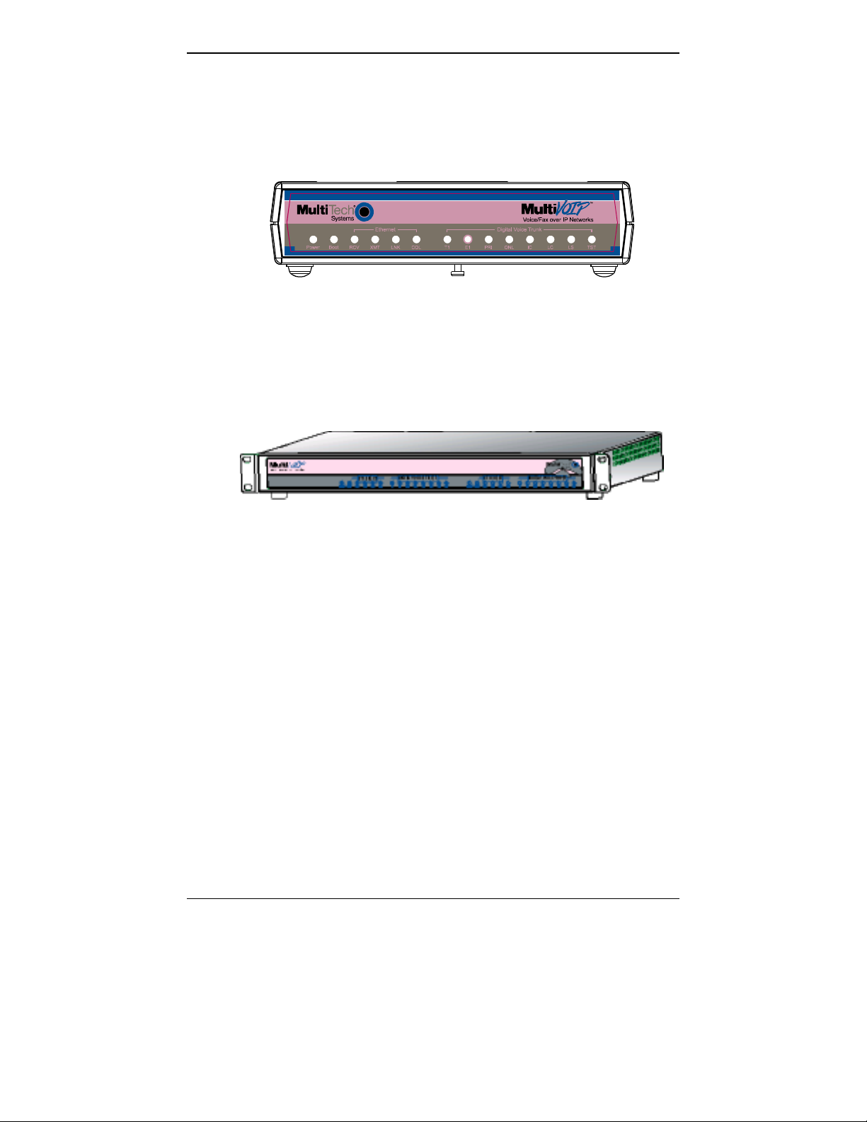
Figure 1-2. MultiVOIP MVP2400 Front Panel
Active LEDs. The MVP2410 front panel has two sets of identical LEDs.
In the MVP2410 as shipped (that is, without an expansion card), the
left-hand set of LEDs is functional where as the right-hand set is not.
When the MVP2410 has been upgraded with an MVP24-48 kit, the
right-hand set of LEDs will al so become active.
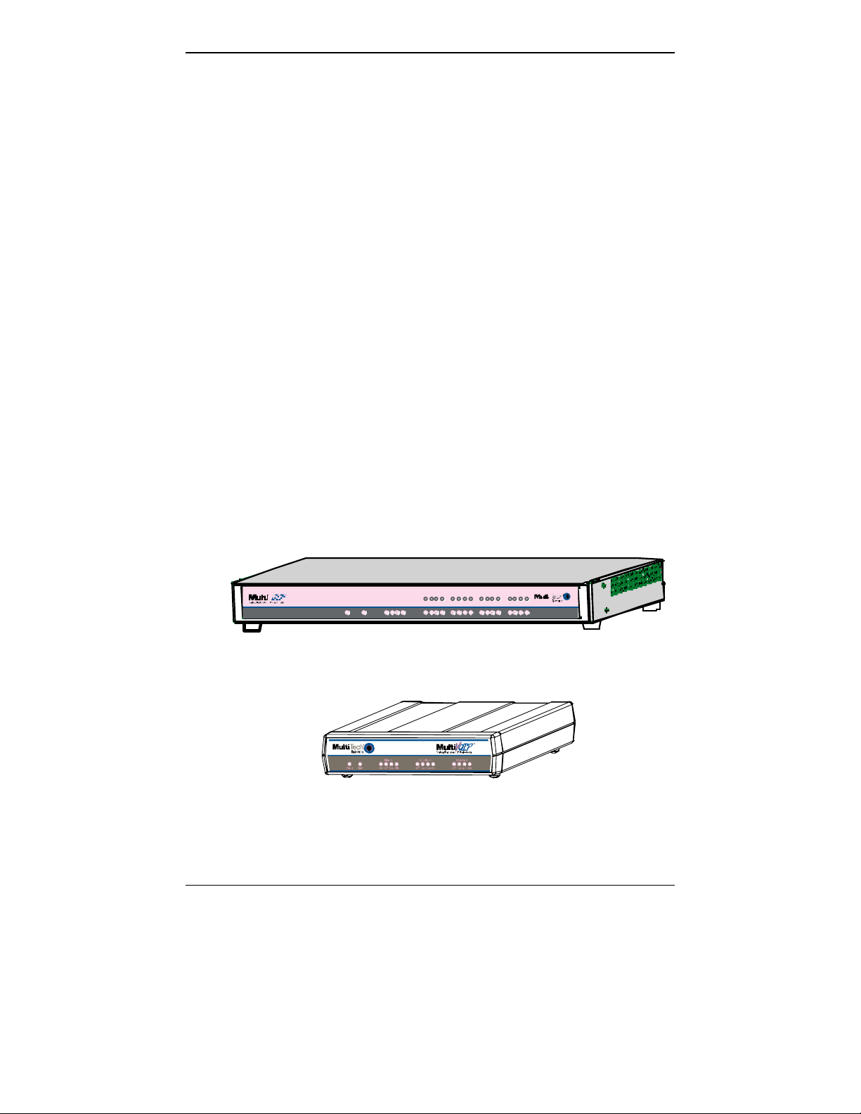
Figure 1-3. MultiVOIP MVP2410 Chassis
12
Page 13

MultiVOIP User Guide Overview
T1 LED Descriptions
The descriptions below apply to all digital T1 MultiVOIP units.
MVP2400/2410 Front Panel LED Definitions
MVP2400/2410 Front Panel LED Definitions
LED NAME DESCRIPTION
Power Indicates presence of power.
Boot
RCV Receive. Lights when receiving data on Ethernet
XMT Transmit. Lights when transmitting data on
LNK Link. When lit, VOIP “sees” the hub or network
COL Colli sion. Lit w hen data collisio ns occur.
T1 When lit, indicates presence of T1 connection.
E1 E1. Not supported.
PRI PRI. On if T1 line is of ISDN-Primary-Rate type.
ONL Online. This LED is on when frame
IC IC LED is on when Internal Clocking is selected in
LC Indicates Loss of Carrier.
LS Indicates Loss of Signal.
After power up, the Boot LED will be on for about 10
seconds while the MVP2400/2410 is booting.
port.
Ethernet port.
via the Ethernet connection.
synchronizatio n has been established on the
T1/E1 link.
T1/E1 configuration.
Test For testing purposes only.
13
Page 14

Overview MultiVOIP User Guide
Introduction to EI MultiVOIPs (MVP3010 & MVP30-60)
We proudly present MultiTech’s E1 Digital Multi-VOIP products. The
MVP3010 is a rack-mount model and the MVP30-60 is an add-on
expansion card that doubles the capacity of the MVP3010 without
adding another chassis. All of these voice-over-IP products have fax
capabilities. All adhere to the European st andard of E1 trunk telephony
using digital 30-channel time-division multiplexing, which allows 30
phone conversations to occur on the E1 line simultaneously. All can
also accommodate E1 lines of the ISDN Primary Rate Interface type
(ISDN-PRI).
Scale-ability. The MVP3010 is tailored to companies needing more
than a few voice-over-IP lines, but not needing carrier-class equipment.
When expansion is needed, the MVP3010 can be field-upgraded into a
dual E1 unit by installing th e MVP30-60 kit, which is essentially a
second MultiVOIP motherboard that fits into an open expansion-card
slot in the MVP3010. The upgraded dual unit then accommodates two
E1 lines.
E1 VOIP Traffic. The MVP3010 accepts its outbound traffic from a E1
trunk that’s connected to either a PBX or to a telco/carrier. The
MVP3010 transforms the telephony signals into IP packets for
transmission on LANs, WANs, or the Internet. Inbound IP data traffic
is converted to telephony data and signaling.
When connected to PBX. When connected to a PBX, the MVP3010
creates a network node served by 10/100-Base T connectio ns. Local
PBX phone extensions gain t oll-free access to all phone stations directly
connected to the VOIP network. Phone extensions at any VOIP location
also gain local-rate access to the e ntire local public-switched telephone
network (PSTN) at every other VOIP location in the system.
When connected to PSTN. When the E1 line(s) connected to the
MVP3010 are connected directly to the PSTN, the unit becomes a Pointof-Presence server dedicated to local calls off-net.
H. 323 & SIP. Being H .323 compatible, the MVP3010 c an place calls t o
telephone equipment at remote IP network locations that also contain
H.323 compatible voice-over-IP gateways. It will interface with H.3 23
software and H.323 gatekeeper units. H.323 specifications also bring to
voip telephony many special features common to conventional
telephony. H.323 features of this kind that have been implemented into
the MuliVOIP include Call Hold, Call Waiting, Call Identification, Call
Forwarding (from the H.450 st andard), and C all T ransfer (H.450.2 from
14
Page 15

MultiVOIP User Guide Overview
H.323 Version 2). The fourth version of the H.323 standard improves
system resource usage (esp. logical port or socket usage) by handling
call signaling more compactly and allowing use of the low-overhead
UDP protocol inste ad of the error-corre cting TCP protocol where
possible.
The MultiVOIP is also SIP-compatible. However, H.450
Supplementary Services features can be used under H.323 only and not
under SIP.
The MultiVOIP3010 comes equippe d with a variety of data
compression capabilities, including G.723, G.72 9, and G.711 and
features DiffServ quality-of-service (QoS) capabilities.
VOIP Functions. The MultiVOIP MVP3010 gateway performs four
basic functions: (a) it converts a dialed number into an IP address, (b) it
sends voice over the data network, (c) it establishes a connection with
another VOIP gateway at a remote site, and (d) it receives voice over
the data network. Voice is handled as IP packets with a variety of
compression options. Each E1 connection to the MultiVOIP provides 30
time-slot channels to connect to the telco or to serve phone or fax
stations connected to a PBX.
Ports. The MVP3010 also has a 10/100 M b ps Ethernet LAN interface,
and a Command port for configuration. An MVP3010 upgraded with
the MVP30-60 kit will have two Ethernet LAN interf aces a nd tw o
Command ports.
Management. Configuration and system management c an be done
locally with the MultiVOIP configuration software. After an IP address
has been assigned locally, other configuration can be done remotely
using the MultiVOIP web browser GUI. Remote system management
can be done with the MultiVoipManager SNMP software or via the
MultiVOIP web browser GUI. All of these control software packages
are included on the Product CD.
15
Page 16

Overview MultiVOIP User Guide
E1 Front Panel LEDs
Because the M V P3010 and MVP30-60 both use a common main circuit
card or motherboard, the LED indicators are the same for both.
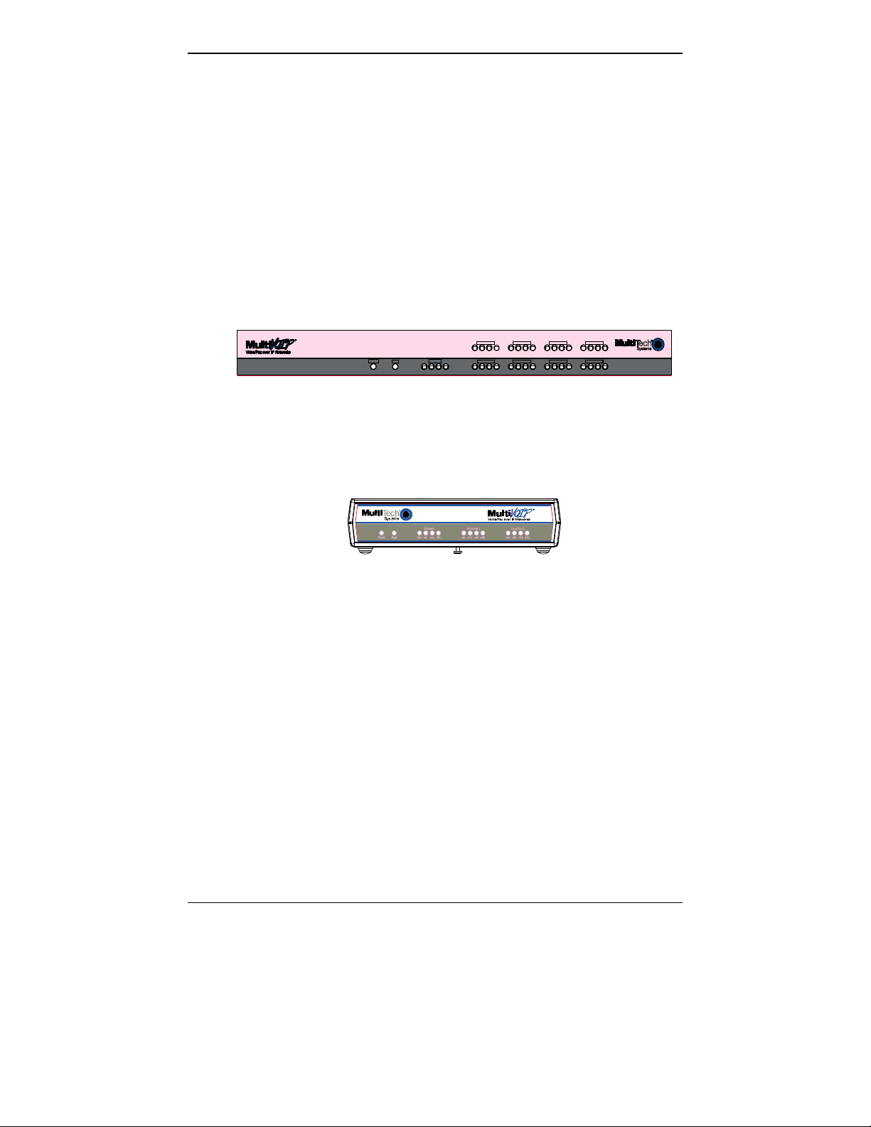
Figure 1-4. MultiVOIP MVP3010 Chassis
Active LEDs. The MVP3010 front panel has two sets of identical LEDs.
In the MVP3010 as shipped (that is, without an expansion card), the
left-hand set of LEDs is functional where as the right-hand set is not.
When the MVP3010 has been upgraded with an MVP30-60 kit, the
right-hand set of LEDs will al so become active.
E1 LED Descriptions
MVP3010 Front Panel LED Definitions
MVP3010 Front Panel LED Definitions
LED NAME DESCRIPTION
Power Indicates presence of power.
Boot
RCV Receive. Lights when receiving data on Ethernet
XMT Transmit. Lights when transmitting data on
LNK Link. When lit, VOIP “sees” the hub or network
COL Colli sion. Lit w hen data collisio ns occur.
After power up, the Boot LED will be on for about 10
seconds while the MVP3010 is booting.
port.
Ethernet port.
via the Ethernet connection.
16
Page 17

MultiVOIP User Guide Overview
MVP3010 Front Panel LED Definitions (cont’d)
T1 T1. Not supported.
E1 E1. When lit, indicates presence of E1
connection.
PRI PRI. On if E1 line is of ISDN-Primary-Rate type.
ONL Online. This LED is on when frame
synchronizatio n has been established on the
T1/E1 link.
IC IC LED is on when Internal Clocking is selected
in T1/E1 configuratio n.
LC Indicates Loss of Carrier.
LS Indicates Loss of Signal.
Test For testing purposes only. For testi ng purposes
only.
17
Page 18

Overview MultiVOIP User Guide
Introduction to Analog MultiVOIPs (MVP-210/410/810 & MVP428)
VOIP: The Free Ride. We proudly present Multi-Tech's MVP210/410/810 generation of MultiVOIP Voice-over-IP Gateways. They
allow voice/fax communication to be trans mitted at no additional
expense over your existing IP network, which has ordinarily been dataonly. To access this free voice and fax communication, you simply
connect the MultiVOIP to your telephone equipment and your existing
Internet connection. These analog MultiVOIPs inter-operate readily
with T1 or E1 MultiVOIPs units.
Capacity. The MultiVOIP model MVP810 is a eight-channel unit, the
MVP410 a four-channel unit, and t he MVP210 a two- channel unit. All
of these MultiVOIP units have a 10/100Mbps Ethernet interface and a
command port for configuration. The M V P428 is an expansion circuit
card for the four-channel MVP410 that turns it into an eight- channel
voip.
Mounting. Mechanically, the MVP410 and MVP810 MultiVOIPs are
designed for a one-high industry-standard EIA 19-inch rack enclosure.
By contrast, the MVP210 is a table-top unit. The product must be
installed by qualified service personnel in a restricted-access area, in
accordance with Articles 110-16, 10-17, and 11 0-18 of the National
Electrical Code, ANSI/NFPA 70.
Phone System Transparency. These MultiVOIPs inter-operate with a
telephone switch or PBX, acting as a s witching device that directs voice
and fax calls over an IP network. The MultiVOIPs have “phonebooks,”
directories which determine to who call s may be made and the
sequences that must be used to complete calls through the MultiVOIP.
The phonebooks allow the phone user to interact with the VOIP system
just as they would with an ordinary PBX or telco switch. When the
phonebooks are set, special dialing sequence s are minimized or
eliminated altogether. Once the call destination is determined, the
phonebook settings determine whether the des tination VOIP unit must
strip off or add dialing digits to make the call appear at its destination
to be a local call.
H.323 & SIP. The MultiVOIP supports the H.323 standards- based
protocol enabling your MultiVOIP to participate in real-time
conferencing with other third-party VOIP Gateways or endpoints that
support the H.323 protocol (for examp le, Microsoft NetMee t ing
H.323 standard defines how endpoints make and receive calls, how
endpoints negotiate a common set of audio and data capabilities, how
information is formatted and sent o ver the network, and how endpoint s
communicate with their respective Gatekeepers.
18
®
). The
Page 19
MultiVOIP User Guide Overview
H.323 specifications also bring to voip telephony many special features
common to conventional telephony. H.323 features of this kind that
have been implemented into the MuliVOIP include Call Hold, Call
Waiting, Call Identification, Call Forwarding (from the H.45 0 standard),
and Call Transfer (H.450.2 from H.323 Version 2). The fourth version of
the H.323 standard improves system resource usage (esp. logical port or
socket usage) by handling call signaling more compactly and allowing
use of the low-overhead UDP protocol instead of the error-correcting
TCP protocol where possible.
The MultiVOIP is also SIP-compatible. However, H.450 Supplementary
Services features can be used under H.323 only and not under SIP.
Gatekeepers. Gatekeeper software is optional and when used in a
network, it typically resides on a de signated PC. It acts as the central
point for all calls within its zo ne and provides call control services to all
registered endpoints. In addition, Gatekeepers can perform bandwidth
management through support for Bandwidth Request, Confirm, and
Reject messages.
Management. Configuration and system management c an be done
locally with the MultiVOIP configuration software. After an IP address
has been assigned locally, other configuration can be done remotely
using the MultiVOIP web browser GUI. Remote system management
can be done with the MultiVoipManager SNMP software or via the
MultiVOIP web browser GUI. All of these control software packages
are included on the Product CD.
Power
XMT RCVXSG RSG XMTRCV XSGRSGXMT RCV XSGRSG
RCV XMT COLLNK XMTRCV XS G RSG
Voice /Fax 1 Voice/Fax 2Voice/Fax 3 Voi ce/Fax 4EthernetBoot
XMT RCVXSG RSG
XMT RCV XSGRSG
XMTRCV XSG RSG
XMTRCV XSG RSG
Vo ice/Fax 5 Voice/Fax 6Voice/Fax 7Voice/ Fax 8
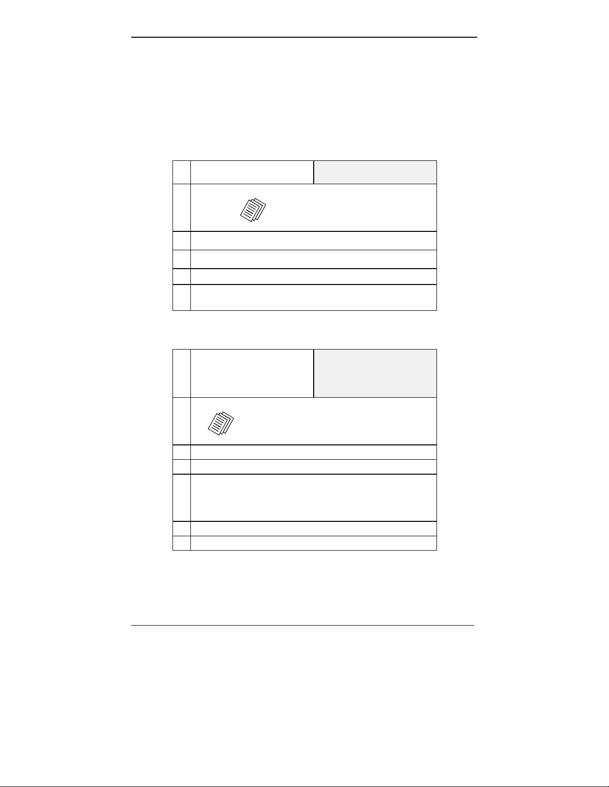
Figure 1-5: MVP-410/810 Chassis
Figure 1-6: MVP-210 Chassis
19
Page 20
Overview MultiVOIP User Guide
Analog MultiVOIP Front Panel LEDs
LED Types. The MultiVOIPs have two types of LEDs on their front
panels:
(1) general operation LED indicators (for power, booti ng, a nd
ethernet functions), and
(2) channel operation LED indicators which describe the data
traffic and performance in each VOIP data channel.
Active LEDs. On both the MVP410 and MVP810, there are eight sets of
channel-operation LEDs. However, on the MVP410, only the lower
four sets of channel-operation LEDs are functional. On the MVP810, all
eight sets are functional.
Voice/Fax 5 Voic e/ Fax 6 Voice/ Fax 7 Voi ce/Fa x 8
Power
Ethernet
Boot
RCV XMT COL LNK
XMT RCV XSG RSG XMT RCV XSG RS G XMT RCV XSG RSG
Voice/ Fax 1
Voice/ Fax 2 Voi ce/Fa x 3
XMT RCV XSG RS G
XMT RCV XSG RSG
Figure 1-7. MVP410/810 Front Panel
XMT RCV XSG RSG
XMT RC V XSG RSG
Voice/ Fax 4
XMT RC V XSG RSG
Similarly, the MVP210 has the general-operation indicator LEDs and
two sets of channel-operation LEDs, one for each channel.
Figure 1-8. MVP210 Front Panel
20
Page 21

MultiVOIP User Guide Overview
Analog MultiVOIP LED Descriptions
MVP-210/410/810 Front Panel LED Definitions
LED NAME DESCRIPTION
General Operation LEDs (one set on each MultiVOIP model)
Power Indicates presence of power.
Boot
After power up, the Boot LED will be on briefly while the
MultiVOIP is booting. It lights whenever the MultiVOIP is
booting or downloading a setup configuration data set.
Ethernet RCV. Receive. Lights (blinks) when receiving data on
Ethernet port.
XMT. Transmit. Lights (blinks) when transmitting
data on Ethernet port. ..
LNK. Link. When lit, VOIP “sees” the hub or network
via the Ethernet connection. ..
COL. Collision. Lit when data collisions occur. ..
Channel-Operation LEDs (one set for each channel)
XMT
RCV
XSG
RSG
Transmit. This indicator blinks when voice packets
are being tran smitted to the local area network.
Receive. This indicator blinks when voice packets
are being received from the local area network.
Transmit Signal. This indicator lights when the FXS-
configured channel is off-hook, the FXO-configured
channel is receiving a ring from the Telco, or the M
lead is active on the E&M configured channel. That is,
it lights when the MultiVOIP is receiving a ring from
the PBX.
Receive Signal. This indicator lights when the FXS-
configured channel is ringing, the FXO-configured
channel has taken the line off-hook, or the E lead is
active on the E&M-configured channel.
21
Page 22

Overview MultiVOIP User Guide
Computer Requirements
The computer on which the MultiVOIP’ s configuration program is
installed must meet these requirements:
• must be IBM-compatible PC wit h M S Windows operating
system;
• must have an available COM port for connection to the
MultiVOIP.
However, this PC does not need to be connected to the MultiVOIP
permanently. It only needs to be connected when local configuration
and monitoring are done. Nearly all configuration and monitoring
functions can be done re motely via the IP network.
22
Page 23

MultiVOIP User Guide Overview
Specifications
Specs for Digital T1 MultiVOIP Units
Digital T1 MultiVOIP Specifications
Parameter
……/Model
Operating
Voltage(s)
Mains
Frequencies
Power
Consumption
Mechanical
Dimensions
Weight
MVP-2410
MVP-2400 MVP-2410
w/ MVP24-48
Expansion
Card
External
transformer:
1.6A@5v
100-240 VAC
1.2 - 0.6 A
100-240 VAC
1.2 - 0.6 A
50/60 Hz 50/60 Hz 50/60 Hz
13 watts 17 watts 27 watts
6.2” W x
9” D x
1.4” H
15.8cm W x
22.9cm D x
3.6cm H
1.8lbs
(.82kg)
1.75”H x
17.4”W x
8.75”D
4.5cm H x
44.2 cm W x
22.2 cm D
7.1 lbs.
(3.2 kg)
1.75”H x
17.4”W x
8.75”D
4.5cm H x
44.2 cm W x
22.2 cm D
7.5 lbs.
(3.4 kg)
2.2lbs (.98kg)
with transformer
23
Page 24

Overview MultiVOIP User Guide
Specs for Digital E1 MultiVOIP Units
Digital E1 MultiVOIP Specifications
Parameter
……/Model
Operating
Voltage(s)
Mains
Frequencies
Power
Consumption
Mechanical
Dimensions
Weight
MVP-3010 MVP-3010
w/ MVP30-60
Expansion
Card
100-240 VAC
1.2 - 0.6 A
100-240 VAC
1.2 - 0.6 A
50/60 Hz 50/60 Hz
17 watts 27 watts
1.75”H x
17.4”W x
8.75”D
4.5cm H x
44.2 cm W x
22.2 cm D
7.1 lbs.
(3.2 kg)
1.75”H x
17.4”W x
8.75”D
4.5cm H x
44.2 cm W x
22.2 cm D
7.5 lbs.
(3.4 kg)
24
Page 25

MultiVOIP User Guide Overview
Specs for Analog MultiVOIP Units
Analog MultiVOIP Specifications
Parameter
……/Model
Operating
Voltage(s)
Mains
Frequencies
Power
Consumption
Mechanical
Dimensions
Weight 1.8lbs (.82kg)
MVP210 MVP410 MVP810
External
transformer:
3A @5V
50/60 Hz 50/60 Hz 50/60 Hz
19 watts 29 watts 46 watt s
6.2” W x
9” D x
1.4” H
15.8cm W x
22.9cm D x
3.6cm H
2.6lbs (1.17kg)
with transformer
100-240 VAC
1.2 - 0.6 A
1.75”H x
17.4”W x
8.5”D
4.5cm H x
44.2 cm W x
21.6 cm D
7.1 lbs.
(3.2 kg)
or
MVP410 + 428
100-240 VAC
1.2 - 0.6 A
1.75”H x
17.4”W x
8.5”D
4.5cm H x
44.2 cm W x
21.6 cm D
7.7 lbs.
(3.5 kg)
25
Page 26

Overview MultiVOIP User Guide
Installation at a Glance
The basic steps of installing yo ur MultiVOIP network involve
unpacking the units, connecting the cables, and configuring the units
using management software (MultiVOIP Configuration software) and
confirming connectivity with another voip site. This process results in a
fully functional Voice-Over-IP network.
Related Documentation
The MultiVOIP User Guide (the document yo u are now reading) comes
in electronic form and is included on your system CD. It presents indepth information on the fea tures and functionality of M ulti-Tech’s
MultiVOIP Product Family.
TM
The CD media is produced using Adobe Acrobat
printing the user guide. To view or print your copy of a user guide,
load Acrobat Reader
on the MultiVOIP CD and is also a free download from Adobe’s Web
Site:
TM
on your system. The Acrobat Reader is included
for viewing and
www.adobe.com/prodindex/acrobat/readstep.html
This MultiVOIP User Guide is also available on Multi-Tech’s Web site
at:
http://www.multitech.com
Viewing and printing a user guide from the Web also requires that you
have the Acrobat Reader loaded on your system. To select the MultiVOIP
User Guide from the Multi- Tech Systems home page, click Documents and then click
MultiVOIP Family in the product list drop-down window. All documents for this
MultiVOIP Product Family will be displayed. You can then choose User Guide
(MultiVOIP Product Family ) to view or downloa d the .pdf file.
26
Page 27

Chapter 2: Quick Start Instructions
27
Page 28

Quick Start Instructions MultiVOIP User Guide
Introduction
This chapter gets the MultiVOIP up and running quickly. The details
we’ve skipped to make this brief can be found elsewhere in the m anual
(see Table of Contents and Index).
MultiVOIP Startup Tasks
Task Summary
●●●● Collecting Phone/IP
Details (vital!)
The MultiVOIP must be configured to
interface with your particular phone
system and IP network. To do so,
certain details must be known about
those phone and IP systems.
●●●● Placement Decide where you’ll mount the voip.
●●●● The Command/Control
Computer:
Specs & Settings
Some modest minimum specifications
must be met. A COM port must be set
up.
●●●● Hookup Connect power, phone, and data cables
per diagram.
●●●● Software Installation This is the configuration program.
It’s a standard Windows software
installation.
●●●● Phone/IP Starter
Configuration
●●●● Phonebook Starter
Configuration
You will enter phone numbers and IP
addresses. You’ll use default parameter
values where possible to get the system
running quickly.
The phonebook is where you specify
how calls will be routed. To get the
system running quickly, you’ll make
phonebooks for just two voip sites.
●●●● Connectivity Test You’ll find out if your voip system can
carry phone calls between two si tes.
That means you’re up and run ning !
●●●● Troubleshooting Detect and remedy any problems that
might have prevented connectivity.
28
Page 29
MultiVOIP User Guide Quick Start Instructions
Phone/IP Details *Absolutely Needed* Before Starting the Installation
Gather IP Information
Ask your computer network
➼
administrator.
IP Network Parameters:
@
• IP Address
• IP Mask
• Gateway
• Domain Name Server (DNS) Info
(not implemented; for future use)
Record for each VOIP Site
in System
Gather Telephone Information
T1 Phone Parameters
➼
Ask phone company or
PBX maintainer.
T1 T elephon y Parameters:
@
• Which frame format is used? ESF___ or D4___
• Which CAS or PRI protocol is used? ______________
• Clocking: Does the PBX or telco switch use
• Which line coding is used? AMI___ or B8ZS___
• Pulse shape level?: (most commonly 0 to 40 meters)
Record for this VOIP Site
internal or external clocking? _________________
Note that the setting used in the voip unit will be the
opposite of the setting used by the telco/PBX.
Info needed to operate:
all MultiVOIP models.
Info needed to operate:
MVP2400
MVP2410
29
Page 30
Quick Start Instructions MultiVOIP User Guide
Phone/IP Details *Absolutely Needed* (cont’d)
Gather Telephone Information
E1 Phone Parameters
➼
Ask phone company or
PBX maintainer.
E1 Telephony Parameters:
@
• Which frame format is used? Double Frame_____
• Which CAS or PRI protocol is used? ______________
• Clocking: Does the PBX or telco switch use
internal or external clocking? _________________
Note that the setting used in the voip unit will be the
opposite of the setting used by the telco/PBX.
• Which line coding is used? AMI___ or HDB3___
• Pulse shape level?: (most commonly 0 to 40 meters)
Record fo r this VOIP Site
MultiFrame w/ CRC4 modified_____
Gather Telephone Information
Info needed to operate:
MVP3010
MultiFrame w/ CRC4_____
Analog Phone Parameters
➼
Ask phone company or
telecom manager.
Analog Telephony Interface Parameters:
@
• Which interface type (or “signaling”) is used?
• If FXS, determine whether the line will be used for a
phone, fax, or KTS (key telephone system)
• If FXO, determine if line will be an analog PBX
extension or an analog line from a telco central office
• If E&M, determine these aspects of the E&M trunk
line from the PBX:
• What is its Type (1, 2, 3, 4, or 5)?
• Is it 2-wire or 4-wire?
• Is it Dial-Tone or Wink?
Record for this VOIP Site
E&M_____ FXS/FXO_____
30
Needed for:
MVP810
MVP410
MVP210
Page 31

MultiVOIP User Guide Quick Start Instructions
Phone/IP Details Often Needed/Wanted
Obtain Email Address for VOIP (for email call log reporting)
required if log repo rts of
VOIP call traffic
are to be sent by email
SMTP Parameters
Preparation Task:
Optional
Ask Mail Server
To: I. T. De pa r tm ent
re: email account for VOIP
administrator to set up
email account (with
password) for the
MultiVOIP unit itself.
Be sure to give a unique
identifier to each
individual MultiVOIP
unit.
voip-unit2@biggytech.com
Get the IP address of the
mail server computer, as
well.
Identify Remote VOIP Site to Call When you’re done installing the MultiVOIP, you’ll want to confirm that
it is configured and operating prop erly. To d o so, it’s good to have
another voip that you can call for testin g purposes. You’ll want to
confirm end-to-end connectivity. You’ll need IP and telephone
information about that remote site.
If this is the very first voip in the system, you’ll want to coordinate the
installation of this MultiVOIP with an installati on of another unit at a
remote site.
Identify VOIP Protocol to be Used
Will you use H.323 or SIP? Each has advantages and disadvantages.
Although it is possible to mix protocols in a single VOIP system, it is
highly desirable to use the same VOIP protocol for all VOIP units in
the system.
31
Page 32

Quick Start Instructions MultiVOIP User Guide
Placement
Mount your MultiVOIP in a safe and convenient location where cab les
for your network and phone system are accessible. Rack-mounting
instructions are in Chapter 3: Mechanical Installation & Cabling.
The Command/Control Computer (Specs & Settings)
The computer used for command and control of the MultiVOIP
(a) must be an IBM-compatible PC,
(b) must use a Micros oft operating system,
(c) must be connected to your local network (Ethernet) system, and
(d) must have an available serial COM port.
The configuration tasks and control tasks the PC will have to do with
the MultiVOIP are not especially de manding. Still, we recommend
using a reasonably new computer. The computer that you use to
configure your MultiVOIP need not be dedicated to the MultiVOIP
after installation is complete.
COM port on controller PC. You’ll need an available COM port on the
controller PC. You’ll need to know which COM port is available for use
with the MultiVOIP (COM1, COM2, etc.).
32
Page 33

MultiVOIP User Guide Quick Start Instructions
Quick Hookups
Hookup for MVP2410 & MVP3010
T1/E1 MultiVOIP Hookup
T1/E1/PRI cabling to your PBX,
and/or to the PSTN.
RJ-45 connector.
Digital Voice
Trunk
(MVP-2410/3010)
Cabling to your IP network.
RJ-45 connector.
Ethernet
Command
10 /100
Cabling to computer running
MultiVOIP software.
RJ-45 to serial connector (DB9).
l
RS-232
O
Grounding
Screw
Hookup for MVP410 & MVP810
Analog MultiVOIP Hookup
MVP810 has 8 connector pairs.
MVP410 has 4 connector pairs.
Only 1 connector of any pair is
used at a time.
FXS/FXO
FXS/FXO
E&M
E&M
FXS/FXO
E&M
FXS/FXO
E&M
Cabling to phone equipment.
E&M (RJ-45 connector):
connects to E&M trunk line
from PBX or telco office.
FXS
(RJ-11 connector):
connects to phone, fax,
or key phone system.
FXO (RJ-11 connector):
connects to analog phone line
or analog PBX extension.
On/Off Switch
MVP-410/810
Cabling to computer running
MultiVOIP software.
Connect or at MultiV O IP: DB-25 .
Connector at computer: DB-9.
FXS/FXO
FXS/FXO
E&M
E&M
FXS/FXO
E&M
FXS/FXO
E&M
Command
Power Cable
Receptacle
Ethernet
Cabling to your IP network.
RJ-45 connector.
Power Cable
Receptacle
Grounding
Screw:
Connect to
Earth Ground
On/Off
Switch
33
Page 34

Quick Start Instructions MultiVOIP User Guide
Hookup for MVP2400
DIGITAL VOICE
TRUNK
T1
PBX
PSTN
Te lephony Connection
Hookup for MVP210
COMMAND
ETHERNET
10/100
RS232
CH1 CH2
FXS/FXO
E&M
E&M
POWER
:
FXS/FXO
1
0
ETHERNET
10/100
Command Port Connection
Network Connection
Hub
RS232
POWER
COMMAND
10BASET
COMMAND PORT
Power Connection
POWER
Voice/Fax Channel 1 - 2
Connections
PSTN
E&M FXO/FXS
E&M
FXO
GND
FXS
Power Connection
Command Port Connection
Ethernet Connection
34
Page 35

MultiVOIP User Guide Quick Start Instructions
Load MultiVOIP Control Software onto PC
For more details, see Chapter 4: Software Inst a lla tion.
1.MultiVOIP must be properly cabled. Power must be turned on.
2.Insert MultiVOIP CD into drive. Allow 10-20 seconds for Autorun to
start. If Autorun fails, go to
My Computer | CD ROM drive | Open. Click Autorun icon.
3.At first dialog box, click Install Soft ware.
4.At ‘welcome’ screen, click Next.
5.Follow on-screen instructions. Accept default program f older
location and click Next.
6. Accept default icon folder location. Click Next. Files will be copied.
7. Select avail ab l e COM port on command/control computer.
8.At completion screen, click Finish.
9. At the prompt “Do you want to run MultiVOIP Configuration?,”
click No. Software installation is complete.
35
Page 36

Quick Start Instructions MultiVOIP User Guide
Phone/IP Starter Configuration
Full details here:
MVP2400
MVP2410
MVP3010
MVP210
MVP410
MVP810
1. Open MultiVOIP program: Start | MultiVOIP xxx | Configuration.
2. Go to Configuration | IP. Enter the IP parameters for your voip site.
3. Do you want to configure and operate the MultiVOIP unit using the
web browser GUI? (It has the same functiona lity as the local
Windows GUI, but offers remote access.)
If NO, skip to step 5.
If YES, continue with step 4.
4. Enable Web Browser GUI (Optional). To do conf iguration and
operation procedures using the web browser GUI, you must first
enable it. To do so, follow these steps.
A. Be sure an IP address has
been assigned to the
MultiVOIP unit (this must be
done in the MultiVOIP
Windows GUI).
B. Save Setup in Windows GUI.
C. Close the MultiVOIP
Windows GUI.
D. Install Java program from
MultiVOIP product CD.
NOTE: Required on first use of
Web Browser GUI only.
Need more
info?
Chapter 5: Technical Configurat ion for
Digital T1/E1 MultiVOIPs
Chapter 6: Technical Configurat ion for
Analog MultiVOIPs
E. Open web browser.
(Note: The PC being used
must be connected to and
have an IP address on the
same IP network that the
voip is on.)
F. Browse to IP address of
MultiVOIP unit.
G. If username and password
have been established, enter
them when prompted by
voip.
H. Use web browser GUI to
configure or operate voip.
See “Web Browser Interface” in Operation &
Maintenance chapter of User Guide (on CD).
Once you’ve begun using the web browser GUI, you can go back to the
MultiVOIP Windows GUI at any time. However, you must log out of
the web browser GUI before using the MultiVOIP Windows GUI.
36
Page 37

MultiVOIP User Guide Quick Start Instructions
5. Go to Configuration | Voice/Fax. Select Coder | “Automatic.” At
the right-hand side of the dialog box, click Default. If you know any
specific parameter values that will apply to your system, enter them.
Click Copy Channel. Select Copy to All. Click Copy. At main
Voice/Fax Parameters screen, click OK to exit from the dialog box.
6. Enter telephone system information.
Analog MultiVOIPs
MVP-210/410/810
Go to
Configuration | Interface.
Enter parameters obtained from
phone company or PBX
administrator.
7. Go to Configuration | Regional Param eters. Select the
Country/Region that fits your situation. Click Default and confirm.
Click OK to exit from the dialog box.
8. Do you want the phone-call logs produced by the MultiVOIP to be
sent out by email (to your Voip Administrator or someone else)?
If NO, skip to step 10.
If YES, continue with step 9.
9. Go to Configuration | SMTP.
SMTP lets you send phone-call log records to the Voip Administrator
by email. Select Enable SMTP.
You should have already obtained an email address for the
MultiVOIP itself (this serves as the origination email account for
email logs that the MultiVOIP can email out automatically).
Digital MultiVOIPs
MVP-2400/2410/3010
Go to
Configuration | T1/E1/ISDN.
Enter parameters obtained from
phone company or PBX
administrator.
Enter this email address in the “Login Name” field.
Type the password for this email account.
Enter the IP address of the email server where the MultiVOIP’s email
account is located in the “Mail Server IP A ddress” field.
Typically the email log reports are sent to t he Voip Administrator
but they can be sent to any email address. Decide where you want
the email logs sent and enter that email address in the “Recipient
Address” field.
37
Page 38

Quick Start Instructions MultiVOIP User Guide
Phone/IP Starter Configuration (continued)
9. (continued) Whenever email log messages are sent out, they must
have a standard Subject line. Something like “Phone Logs for Voip
N” is useful. If you have more than one MultiVoip unit in the
building, you’ll need a unique identif ier f or each one (select a useful
name or number for “N”). In this “Subject” field, enter a useful
subject title for the log messages.
In the “Reply-To Address” field, enter the email address of your Voip
Administrator.
10. Go to Configuration | Logs.
Select “Enable Console Messages.” (Not applicable if using Web GUI.)
To allow log reports by email (if desired ), click SMTP. Click OK.
To do logging with a SysL og client program, click on “SysLo g Server
– Enable” in the Logs screen. To implement this function, you must
install a SysLog client pro gram. For more info, see the “SysLog
Server Functions” section of the Operation & Maintenance chapter of
User Guide.
the
11. Enable premium (H.450) telephony features.
Go to Supplementary Services. Select any features to be used.
For Call Hold, Call Transfer, & Call Waiting, specif y the key sequence
that the phone user will press to invoke the feature. For Call Name
Identification, specify the allowed name types to be used and a
caller-id descriptor.
If Call Forwarding is to be used, enable this feature in the
Add/Edit Inbound Phone Book screen.
12. Go to Save Setup | Save and Reboot. Click OK. This will s ave the
parameter values that you have just entered.
The MultiVOIP’s “BOOT” LED will light up while the configuration
file is being saved and loaded into the MultiVOIP. Don’t do an ything
to the MultiVOIP until the “BOOT “L ED is off (a loss of power at t his
point could cause the MultiVOIP unit to lose the configuration
settings you have made).
END OF PROCEDURE.
38
Page 39

MultiVOIP User Guide Quick Start Instructions
Phonebook Starter Configuration (with remote voip)
To do this part of the quick setup, you need to know of another voip
that you can call to conduct a test. It should be at a remote location,
typically somewhere outside of your b uild ing. You must know the
phone number and IP address for that site. We are assuming here that
the MultiVOIP will operate in conjunction with a PBX.
You must configure both the Outbound Phonebook and the Inbound
Phonebook. A starter configuration only means that two voip locations
will be set up to begin the system and est ablish voip communication.
Outbound Phonebook
1. Open the MultiVOIP program
(Start | MultiVOIP xxx | Configuration
2. Go to Phone Book | PhoneBook Modify | Outbound Phonebook
| Add Entry.
3. On a sheet of paper, write down the calling code of the remote voip
(area code, country code, city code, etc.) that you’ll be calling.
Follow the example that best fits your situation.
North America,
Long-Distance Example
Technician in Seattle (area
206) must set up one voip
there, another in Chicago
(area 312, downtown) .
Answer: Write down 312.
Euro, National Call
Example
Technician in centr al
London (area 0207) to set
up voip there, another in
Birmingham (area 0121).
Answer: write down 0121.
Euro, International Call Example
Technician in Rotterdam (country 31; city 010) to
set up one voip there, another in Bordeaux
(country 33; area 05).
Answer: write down 3305.
39
Page 40

Quick Start Instructions MultiVOIP User Guide
4. Suppose you want to call a phone number outside of your building
using a phone station that is an extension from your PBX sy stem (if
present). What digits must you dial? Often a “9” or “8” must be
dialed to “get an outside line” through the PBX (i.e., to connect to the
PSTN). Generally, “1 “or “11” or “0” must be dialed as a prefix for
calls outside of the calling code area (long-distance calls, national
calls, or international calls).
On a sheet of paper, write down the digits you must dial before you
can dial a remo t e area code.
North America,
Euro, National Call
Long-Distance Example
Seattle-Chicago sy stem.
Seattle voip works with
PBX that uses “ 8” for all
voip calls. “1” must
immediately precede area
code of dialed number.
Answer: write down 81.
London/Birming. system.
London voip works with
PBX that uses “ 9” for all
out-of-building calls
whether by voip or by
PSTN. “0” must
immediately precede area
code of dialed number.
Answer: write down 90.
Euro, International Call Example
Rotterdam/Bordeaux system.
Rotterdam voip works with PBX where “9” is
used for all out-of-building calls. “0” must
precede all international calls.
Answer: write down 90.
Example
40
Page 41

MultiVOIP User Guide Quick Start Instructions
5. In the “Destination Pattern” field of the Add/Edit Outbound
Phonebook screen, enter the digits from step 4 followed by the digits
from step 3.
North America,
Euro, National Call
Long-Distance Example
Seattle-Chicago sy stem.
Answer: enter 81312 as
Destination Pattern in Outbound
Phone-book of
Seattle voip.
London/Birming. system.
Leading zero of
Birmingham area code is
dropped when combined
with national-dialing
access code. (Such
practices vary by country.)
Answer: enter 90121 as
Euro, International Call Example
Rotterdam/Bordeaux system.
Answer: enter 903305 as Destination Patter n in
Outbound Phonebook of Rotterdam voip.
Example
Destination Pattern in Outbound
Phonebook of
London voip.
Not 900121.
41
Page 42

Quick Start Instructions MultiVOIP User Guide
6. Tally up the number of digits that must be dialed to reach the remote
voip site (including prefix digits of all types). Enter this number in
the “Total Digits” field.
North America,
Long-Distance Example
Seattle-Chicago system.
To complete Seattle-to-
Chicago call, 81312 must be
followed by the 7-digit local
phone number in Chicago.
Answer: enter 12 as number
of Total Digits in
Outbound Phonebook of Seattle
voip.
Euro, National Call
Example
London/Birming. system.
To complete London-to-
Birmingham call, 90121 must
be followed by the 7-digit
local phone number in
Birmingham.
Answer: enter 12 as number
of Total Digits in
Outbound Phonebook of London
voip.
Euro, International Call Example
Rotterdam/Bord eaux system.
To complete Rotterdam-to-Bordeaux call, 903305 must
be followed by 8-digit local phone number in Bordeaux.
Answer: enter 14 as number of Total Digits in
Outbound Phonebook of Rotterdam voip.
7. In the “Remove Prefix” field, enter the initial PBX access digit
(“8” or “9”).
North America,
Long-Distance Example
Seattle-Chicago system.
Answer: enter 8 in “Remove
Prefix” field of
Seattle Outbound
Phonebook.
Euro, National Call
Example
London/Birming. system.
Answer: enter 9 in “Remove
Prefix” field of
London Outbound
Phonebook.
Euro, International Call Example
Rotterdam/Bord eaux system.
Answer: enter 9 in “Remove Prefix” field of Outbound
Phonebook for Rotterdam voip.
Some PBXs will not ‘hand off’ the “8” or “9” to the voip. But for those PBX
units that do, it’s important to enter the “8” or “9” in the “Remove Prefix”
42
Page 43

MultiVOIP User Guide Quick Start Instructions
field in the Outbound Phonebook. This precludes the problem of having to
make two inbound phonebook entries at remote voips, one to account for
situations where “8” is used as th e PBX access digit, and another for wh en
“9” is used.
8. Select the voip protocol that you will use (H.323 or SIP).
9. Click OK to exit from the Add/Edit Outbound Phonebook screen.
Inbound Phonebook
1. Open the MultiVOIP program.
(Start | MultiVOIP xxx | Configuration
2. Go to Phone Book | PhoneBook Modify | Inbound Phonebook
| Add Entry.
3. In the “Remove Prefix” field, enter your local calling code (area code,
country code, city code, etc.) preceded by any other “access digits”
that are required to reach your local site from the remote voip
location (think of it as though the call were being made through the
PSTN – even though it will not be).
North America,
Long-Distance Example
Seattle-Chicago system.
Seattle is area 206. Chicago
employees must dial 81
before dialing any Seattle
number on the voip system.
Answer: 1206 is pref ix to be
removed by local
(Seattle) voip.
Euro, National Call
Example
London/Birming. system.
Inner London i s 0207 area.
Birmingham employees must
dial 9 before dialing any
London number on the voip
system.
Answer: 0207 is prefix to be
removed by local
(London) voip.
Euro, International Call Example
Rotterdam/Bord eaux system.
Rotterdam is countr y code 31, city code 010. Bordeaux
employees must dial 903110 before dialing any
Rotterdam number on the voip system.
Answer: 03110 is prefix to be removed by local
(Rotterdam) voip.
43
Page 44

Quick Start Instructions MultiVOIP User Guide
4. In the “Add Prefix” field, enter any d igits that must be dialed from
your local voip to gain access to the PSTN.
North America,
Long-Distance Example
Seattle-Chicago system.
On Seattle PBX, “9” is used to
get an outside line.
Answer: 9 is prefix to be
added by local
(Seattle) voip.
Euro, National Call
Example
London/Birming. system.
On London PBX, “9” i s used
to get an outside line.
Answer: 9 is prefix to be
added by local
(London) voip.
Euro, International Call Example
Rotterdam/Bord eaux system.
On Rotterdam PBX, “9” is used to get an outside line.
Answer: 9 is prefix to be added by local (Rotterdam)
voip.
5. In the “Channel Number” field, enter “0.” A zero value means the
voip unit will assign the call to an available channel. If desired,
specific channels can be assigned to specific incoming calls (i.e., to
any set of calls received with a particul ar incoming dialing pattern).
44
Page 45

MultiVOIP User Guide Quick Start Instructions
6. In the “Description” field, it is useful to describe the ultimate
destination of the calls. For example, in a New York City voip
system, “incoming calls to Manhattan office,” might describe a
phonebook entry, as might the descriptor “incoming calls to NYC
local calling area.” The description should make the routing of calls
easy to understand. (40 characters max.)
North America,
Long-Distance Example
Seattle-Chicago system.
Possible Description:.
Free Seattle access, all
employees
Euro, National Call
Example
London/Birming. system.
Possible Description:.
Local-rate London access,
all empl.
Euro, International Call Example
Rotterdam/Bord eaux system.
Possible Description:. Local-rate Rotterdam access, all
empl.
7. Repeat steps 2-6 for each inbound phonebook e nt ry. When all entries
are complete, go to step 8.
8. Click OK to exit the inbound phonebook screen.
9. Click on Save Setup. Highlight Save and Reboot. Click OK.
Your starter inbound phonebook co nfiguration is complete.
45
Page 46

Quick Start Instructions MultiVOIP User Guide
Phonebook Tips
Preparing the phonebook for your voip system is a complex task that, at
first, seems quite daunting. These tips may make the task easier.
Use Dialing Patterns, Not Complete Phone Numbers. You will not
1.
generally enter complete phone numbers in the voip phonebook.
Instead, you’ll enter “destination patterns” that involve area codes and
other digits. If the destination pattern is a whole area code, you’ll be
assigning all calls to that area code to go to a particular voip which has
a unique IP address. If your destination pattern includes an area code
plus a particular local phone exchange number, then the scope of calls
sent through your voip system will be narrowed (only calls within that
local exchange will be handled by the designated voip, not all calls in
that whole area code). In general, when there are fewer digits in your
destination pattern, you are asking the voip to handle calls to more
destinations.
The Four Types of Phonebook Digits Used. Important!
2.
“Destination patterns” to be entered in your phonebook will generally
consist of:
(a) calling area codes,
(b) access codes,
(c) local exchange numbers, and
(d) specialized codes.
Although voip phonebook entries m ay look confusing at first, it’s
useful to remember that all the digit s in any phonebook entry must be
of one of these four types.
calling area codes. There are different names for these around the
(a)
world: “area codes,” “city code s,” “country codes,” etc. These codes,
are used when making non-local calls. They always precede the phone
number that would be dialed when making a local call.
46
Page 47

MultiVOIP User Guide Quick Start Instructions
(b) access codes. There are digits (PSTN access codes) that must be
dialed to gain access to an operator, to access the publicly switched
‘long-distance’ calling system(North America), to access the publicly
switched ‘national’ calling system (Europe and elsewhere), or to access
the publicly switched ‘international’ ca lling system (worldwide).
There are digits (PBX access codes) that must be dialed by phones
connected to PBX systems or key systems. Often a “9” must be dialed
on a PBX phone to gain access to the PSTN (‘to get an outside line’).
Sometimes “8” must be dialed on a PBX phone to div ert calls onto a
leased line or to a voip system. However, sometimes PBX systems are
‘smart’ enough to route calls to a voip system without a special access
code (so that “9” might still be used for all calls outside of the build ing).
There are also digits (special access codes) that must be dialed to gain
access to a particular discount long-distance carrier or to some other
closed or proprietary telephone system.
local exchange numbers. Within any calling area there will be many
(c)
local exchange numbers. A single exchange may be used for an entire
small town. In cities, an exchange may be used for a particular
neighborhood (although exchanges in cities do not always cover easily
discernible areas). Organizations like businesses, governments,
schools, and universities are also commonly assigned exchange
numbers for their exclusive use. In some cases, these organizationalassigned exchanges can become non-localized because the exchange is
assigned to one facility and linked, by the organization’s private
network, to other sometimes distant locations.
specialized codes. Some proprietary voip units assign, to sites and
(d)
phone stations, numbers that are not compatible with PSTN
numbering. This can also occur in PBX or key systems. These
specialized numbers must be handled on a case-by-case basis.
Knowing When to Drop Digits. Example
3.
When calling area codes and
access codes are used in
combination, a leading “1” or “0”
must sometimes be dropped.
Phonebook Entry ➠
Area code for Inner London is
listed as “0207.” However, in
international calls the leading
“0” is dropped.
U.K.
Country
Code
➠
➠➠
International
Access Code
Leading Zero
Dropped from
Area Code
47
Page 48

Quick Start Instructions MultiVOIP User Guide
4. Using a Comma. Detail
Commas are used in telephone
dialing strings to indicate a pause
to allow a dial t one to appear
(common on PBX and key
systems). Commas may be used
only in the “Add Prefix” field of
the Inbound Phonebook.
5. Ease of Use. The phonebook setup determines how easy the voip
system is to use. Generally, you’ll wa nt to make it so dialing a voip call
is very similar to dialing any other number (on the PSTN or through the
PBX).
Avoid Unintentional Calls to Official/Emergency Numbers. Dialing a
6.
voip call will typically be somewhat different than ordinary dialing.
Because of this, it’s possible to set up situations, quite unwittingly,
where phone users may be predisposed to call official numbers without
intending to do so. Conversely, a voip/PBX system might also make it
difficult to place an official/emergency call when one intends to do so.
Study your phonebook setup and do some dialing on the system to
avoid these pitfalls.
, = 1-second pause
in many PBX systems
(not needed in all)
Inbound/Outbound Pattern Matching. In general, the Inbound
7.
Phonebook entries of the local voip unit will match the Outbound
Phonebook entries of the remote voip unit. Similarly, the Outbound
Phonebook entries of the local voip unit will match the Inbound
Phonebook entries of the remote voip unit. There will often be nonmatching entries, but it’s nonetheless useful to notice the matching
between the phonebooks.
Simulating Network in-lab/on-benchtop. One common method of
8.
configuring a voip network is to to set up a local IP network in a lab,
connect voip units to it, and perhaps have phones connected on channel
banks to make test calls.
48
Page 49

MultiVOIP User Guide Quick Start Instructions
Phonebook Example
Boise Office
PBX System.
Main Number:
333-2700
Inbound Phonebook
Inbound Phonebook
Each
two entries. The first entry (4 digits)
specifies how incoming calls from the
other voip sites will be handled if
they go out onto the local PSTN.
Essentially, all those calls come to the
receiving voip wit h a pattern
beginning with
voip removes those four digits
because they aren’t needed when
dialing locally. The local voip
attaches a “9” at the beginning of the
number to ge t an outside line. The
PBX then completes the call to the
PSTN.
The second
(8 digits) is for receiving calls from
company employees in the other two
cities. The out-of-town employee
simply dials 3 digits. The first of the
three digits is uniquely used at each
site and so acts as a destination
pattern (Boise extensions are 7xx,
Santa Fe extensions 2xx, Fl agstaff
extensions 6xx).
As the remote voip sends out the call,
it automatically attaches all of the
foregoing digits that would normally
have to be dialed using the PSTN.
The local (receiving) voip sees the
extended pattern in its Inbound
Phonebook and so strips off the long
telltale pattern of digits needed for 3digit calling. It must finally add back
the last digit before handing the call
to the PBX, which completes the call
to a specific extension.
Area: 208
90 extensions
204.16.49.73
24-Channel
Digital VoIP
(MVP2410)
1+area code. The local
Inbound
Phonebook entry
contains
Flagstaff Office
Area: 520
204.16.49.75
8-Channel
Analog VoIP
(MVP810)
PSTN
One Common Situation
Voip Exampl e. This company has offices in three
different cities. The PBX units all operate alike.
Notably, they all give access to outside lines using
“9.” They all are ‘smart’ enough to identify voip calls
without using a special access digit (“8” is used in
some systems). Finally, the system operates so that
employees in any office can dial empl oy ees in any
other office using only three digits. Here are the
phonebooks needed for that sy stem.
Santa Fe Office
Area: 505
204.16.49.74
8-Channel
Analog VoIP
(MVP810)
IP
Network
Outbound Phonebook
Each
pairs of entries, two entries for each
remote site. Whenever an out-of-town
employee dials a 12-dig it number
beginning with the listed 5-digit
destination pattern (9+1+area code) of
another company l ocation, the PBX
hands the call to the voip system. The
local voip strips off the “9” and directs
the call to the IP address of the remote
voip. The remote voip receives th e call
and hands it to its PBX. The PBX then
completes the call to the PSTN.
The one-digit
patterns pertain t o 3-digit calling
between comp any employees.
PBX System.
Main Number:
444-3200
PSTN
Outbound
40 extensions
contains two
destination
PBX System.
Main Number:
777-5600
30 extensions
PSTN
49
Page 50

Quick Start Instructions MultiVOIP User Guide
Boise Office
PBX System.
Main Number:
333-2700
Area: 208
PSTN
90 extensions
Boise Voip Boise Voip
Inbound Phonebook Outbound Phonebook
Prefix to
Remove
1208 9 Incoming calls
12083332 2 Incoming calls
204.16.49.73
24-Channel
Digital VoIP
(MVP2410)
IP
Network
Santa Fe Voip Santa Fe Voip
Inbound Phonebook Outbound Phonebook
Prefix
to Add
Description
Incoming Cal ls
to PSTN,
Santa Fe local
calls
to extensions
of company’s
PBX system
in Santa Fe
Prefix to
Remove
1505 9, Incoming calls
150544432 2 Incoming calls
Total
Digits
Prefix to
Remove
Destin.
Pattern
91208 12 9 none 204.
7 3 none 1208
91520 12 9 none 204.
6 3 none 1520
Prefix
to Add
Prefix
to AddIPAddr
333
2
777
5
Description
Incoming Calls
to PSTN,
Boise Area
to extensions
of company’s
PBX system
in Boise
16.49.
73
204.1
6.49.
73
16.49.
75
204.
16.49.
75
Tot al
Digits
Prefix to
Remove
PBX System.
Main Number:
444-3200
Destin.
Pattern
91505 12 9 none
2 3 none 1505
91520 12 9 none 204.1
6 3 none 1520
Description
Outgoing Calls
Outgoing calls
to Boise area
Outgoing calls
to extensions
of company’s
Boise PBX (3digit dialing)
Outgoing calls
to Flagstaff
area
3-digit calls to
Flagstaff
employees
Prefix
to AddIPAddr
444
3
777
5
Santa Fe Of fic e
Description
Outgoing Calls
204.16
Outgoing calls
.49.74
to Santa Fe
area
204.16
3-digit calls to
.49.74
Santa Fe
employees
Outgoing calls
6.49.7
to Flagstaff
5
area
204.1
3-digit calls to
6.49.7
Flagstaff
5
employees
Area: 505
204.16.49.74
8-Channel
Analog VoIP
(MVP810)
40 extensions
PSTN
Flagstaff Office
Area: 520
204.16.49.75
8-Channel
Analog VoIP
(MVP810)
PBX Syste m .
Main Number:
777-5600
30 extensions
Prefix to
Remove
1520 9 Incoming calls
15207775 5 Incoming calls
PSTN
Flagstaff Voip Flagstaff Voip
Inbound Phonebook Outbound Phonebook
Prefix
to Add
Description
Incoming Calls
to PSTN,
Flagstaff local
calls
to extensions
of company’s
PBX system
in Flagstaff
Tota l
Prefix to
Destin.
Digits
Pattern
91505 12 9 none
2 3 no ne 1505
91208 12 9 none
7 3 no ne 1208
Remove
Prefix
to AddIPAddr
444
3
333
2
50
204.16
.49.74
204.16
.49.74
204.16
.49.73
204.16
.49.73
Description
Outgoing Calls
Outgoing calls
to Santa Fe
area
3-digit calls to
Santa Fe
employees
Outgoing calls
to Boise area
3-digit calls to
Boise
employees
Page 51

MultiVOIP User Guide Quick Start Instructions
Sample Phonebooks Enlarged
Boise Voip Boise Voip
Inbound Phonebook Outbound Phonebook
Prefix
Prefix to
Remove
1208 9, Incoming calls
120833327 7 Incoming calls
to Add
Description
Incoming Calls
to PSTN,
Boise Area
to extensions
of company’s
PBX system
in Boise
Santa Fe Voi p Santa Fe Voip
Inbound Phonebook Outbound Phonebook
Prefix to
Remove
1505 9, Incoming calls
150544432 2 Incoming calls
Prefix
to Add
Destin.
Pattern
91505 12 9 none
2 3 none 1505
91520 12 9 none 204.
6 3 none 1520
Description
Incoming Calls
to PSTN,
Santa Fe local
calls
to extensions
of company’s
PBX system
in Santa Fe
Total
Prefix to
Remove
Prefix
to AddIPAddr
444
3
777
5
Total
Digits
Prefix to
Remove
Digits
Destin.
Pattern
91208 12 9 none 204.
7 3 none 1208
204.
16.49.
74
204.
16.49.
74
16.49.
75
204.
16.49.
75
Description
Outgoing Calls
Outgoing calls
to Santa Fe
area
3-digit calls to
Santa Fe
employees
(extensions
200 to 240)
Outgoing calls
to Flagstaff
area
3-digit calls to
Flagstaff
employees
(extensions
600-630)
Prefix
to AddIPAddr
333
2
91520 12 9 none 204.
6 3 none 1520
777
5
16.49.
73
204.
16.49.
73
16.49.
75
204.
16.49.
75
Description
Outgoing Calls
Outgoing calls
to Boise area
3-digit calls to
Boise
employees
(extensions
700-790)
Outgoing calls
to Flagstaff
area
3-digit calls to
Flagstaff
employees
(extensions
600-630)
Flagstaff Voip Flagstaff Voip
Inbound Phonebook Outbound Phonebook
Prefix
Prefix to
Remove
1520 9, Incoming calls
152077756 6 Incoming calls
to Add
Description
Incoming Calls
to PSTN,
Flagstaff local
calls
to extensions
of company’s
PBX system
in Flagst af f
Destin.
Pattern
91505 12 9 none
2 3 none 1505
91208 12 9 none
Total
Digits
Prefix to
Remove
7 3 none 1208
51
Prefix
to AddIPAddr
204.16
.49.74
204.16
.49.74
444
3
204.16
.49.73
204.16
.49.73
333
2
Description
Outgoing Calls
Outgoing calls
to Santa Fe
area
3-digit calls to
Santa Fe
employees
(extensions
200-240)
Outgoing calls
to Boise area
3-digit calls to
Boise
employees
(extensions
700-790)
Page 52

Quick Start Instructions MultiVOIP User Guide
Phonebook Worksheet
Voip Location/ID:_______________ _____________
Inbound Phonebook Outbound Phonebook
Prefix
Prefix to
Remove
to Add
Other Details:
Inbound Phonebook Outbound Phonebook
Prefix to
Remove
Description
Incoming Calls
Destin.
Pattern
Voip Location/ID:____________________________
Prefix
Description
to Add
Incoming Calls
Total
Digits
Destin.
Pattern
Prefix to
Remove
Tot al
Digits
Prefix
to AddIPAddr
Prefix to
Remove
Description
Outgoing Calls
Prefix
to AddIPAddr
Description
Outgoing Calls
Other Details:
Voip Location/ID:_______________ _____________
Inbound Phonebook Outbound Phonebook
Prefix
Prefix to
Remove
to Add
Description
Incoming Calls
Destin.
Pattern
Total
Digits
Prefix to
Remove
Prefix
to AddIPAddr
Other Details:
52
Description
Outgoing Calls
Page 53

MultiVOIP User Guide Quick Start Instructions
Enlarged Phonebook Worksheet
53
Page 54

Quick Start Instructions MultiVOIP User Guide
Connectivity Test
The procedures “Phone/IP Start er Configurati on” and “Phonebook
Starter Configuration” must be completed before you can do this
procedure.
1. These connections must be made:
Connections
for digital MultiVOIPs
(MVP-2400/2410/3010
MultiVOIP to local PBX MultiVOIP to local phone
MultiVOIP to command PC MultiVOIP to command PC
MultiVOIP to Internet MultiVOIP to Internet
2. Inbound Phonebook and Outbound Phonebook must both be set up
with at least one entry in each. These entries must allow for
connection between two voip units.
for analog MultiVOIPs
(MVP-210/410/810)
station
–OR-MultiVOIP to extension of
key phone system
3. Console messages must be enabled. (If this has not been done
already, go, in the MultiVOIP GU I, to Configuration | Logs and
select the “Console Messages” checkbox.
4. You now need to free up the COM port connection (currently being
used by the MultiVOIP program) so that the HyperTerminal program
can use it. To do this, you can either (a) click on Connection in the
sidebar and select “Disconnect” from the drop-down box, or (b) close
down the MultiVOIP program altogether.
5. Open the HyperTerminal program.
54
Page 55

MultiVOIP User Guide Quick Start Instructions
6. Use HyperTerminal to receive and record console messages from the
MultiVOIP unit. To do so, set up HyperTerminal as follows (setup
shown is for Windows NT4; details will differ slightly in other MS
operating systems):
In the upper toolbar of the HyperTerminal screen, click on
the Properties button.
In the “Connect To” tab of the Connection Properties
dialog box, click on the Configure button.
In the next dialog box, on the “General” tab, set “Maximum
Speed” to 115200 bps.
On the “Connection” tab, set connection preferences to:
Data bits: 8
Parity: none
Stop bits: 1
Click OK twice to exit settings dialog boxe s.
7. Make VOIP call.
for digital MultiVOIPs
(MVP-2400/2410/3010
Make call from an extension
of the local PBX.
for analog MultiVOIPs
(MVP-210/410/810)
Make call on a local phone
line accessing PSTN directly
or through key system
55
Page 56

Quick Start Instructions MultiVOIP User Guide
8. Read console messages recorded on HyperTerminal.
Console Messages from Originating VOIP. The voip unit that
originates the call will send back messages like that shown below.
[00026975] CAS[0] : RX : ABCD = 1, 1, 1, 1,Pstn State[1]
TimeStamp : 26975
[00027190] CAS[0] : TX : ABCD = 1, 1, 1, 1
[00027190] PSTN: cas seizure detected on 0
[00027440] CAS[0] : TX : ABCD = 0, 0, 0, 0
[00033290] PSTN:call detected on 0 num=17637175662*
[00033290] H323IF[0]:destAddr =
TA:200.2.10.5:1720,NAME:Mounds
View,TEL:17637175662,17637175662
[00033290] H323IF[0]:srcAddr = NAME:New
York,TA:200.2.9.20
[00033440] H323IF [0]:cmCallStateProceeding
[00033500] H323[0]: Remote Information (Q931): MultiVOIP
- T1
[00033565] CAS[0] : TX : ABCD = 1, 1, 1, 1
[00033675] H323IF [0]: MasterSlaveStatus=Slave
[00033675] H323IF[0]:FastStart Setup Not Used
[00033690] CAS[0] : TX : ABCD = 1, 1, 1, 1
[00033755] H323IF[0]: Coder used 'g7231'
[00033810] PSTN:pstn call connected on 0
56
Page 57

MultiVOIP User Guide Quick Start Instructions
Console Messages from Terminating VOIP. The voip unit connected
to the phone where the call is answered will send back messages like
that shown below.
[00170860] H323[0]: New incoming call
[00170860] PSTNIF : Placing call on channel 0 Outbound
digit 7175662
[00170885] CAS[0] : TX : ABCD = 1, 1, 1, 1
[00171095] H323IF [0]: MasterSlaveStatus=Master
[00171105] CAS[0] : RX : ABCD = 1, 1, 1, 1,Pstn State[7]
TimeStamp : 171105
[00171105] H323IF[0]: Coder used 'g7231'
[00171110] H323IF[0]:FastStart Setup Not Used
[00171110] H323IF[0]: Already opened the out goi ng log ica l
channel
[00171110] H323IF[0]: Coder used 'g7231'
[00171315] CAS[0] : RX : ABCD = 0, 0, 0, 0,Pstn State[9]
TimeStamp : 171315
[00172275] PSTN: dialing digit ended on 0
[00172285] PSTN: pstn proceeding indication on 0
[00172995] CAS[0] : RX : ABCD = 1, 1, 1, 1,Pstn State[12]
TimeStamp : 172995
[00173660] CAS[0] : TX : ABCD = 1, 1, 1, 1
[00173760] PSTN:pstn call connected on 0
9. When you see the following message, end-to-end voip connectivity
has been achieved.
“PSTN: pstn call connected on X”
where x is the number of the voip channel carrying the call
10. If the HyperTerminal messages do not confirm connectivity, go to
the Troubleshooting procedure below.
57
Page 58

Quick Start Instructions MultiVOIP User Guide
Troubleshooting
If you cannot establish connectivity between two voips in the system,
follow the steps below to determine the problem.
1. Ping both MultiVOIP units to confirm connectivity to the network.
2. Verify the telephone connections.
A. For MVP2400, MVP2410, or MVP3010.
Check cabling. Are connections well seated? To correct receptacle?
Is the ONL LED on?
(If on, ONL indicates that the MultiVOIP is online on the
network.)
Are T1/E1/PRI Parameter settings correct?
B. For MVP210, MVP410, or MVP810.
Check cabling. Are connections well seated? To correct receptacle?
Are telephone Interface Parameter settings correct?
3. Verify phonebook configuration.
4. Observe console messages while placing a call. Look for error
messages indicating phonebo ok problems, network problems, voicecoder mismatches, etc.
58
Page 59

Chapter 3: Mechanical Installation
and Cabling
59
Page 60

Mechanical Installation & Cabling MultiVOIP User Guide
Introduction
The MultiVOIP models MVP210 and MVP2400 are table-top units and
can be handled easily by one person. H owever, the M VP410, MVP810,
MVP2410, and MVP3010 are somewhat heavier units. When thes e
units are to be installed into a rack, two able-bodied persons should
participate.
Please read the safety notices before beginning installation.
Safety Warnings
Lithium Battery Caution
A lithium battery on the voice/fax channel board provides backup
power for the timekeeping capability. The battery has an estimated life
expectancy of ten years.
When the battery starts to weaken, the date and time may be incorrect.
If the battery fails, the board must be sent back to Multi-Tech Systems
for battery replacement.
Warning: There is danger of explosion if the battery is incorrectly
replaced.
Safety Warnings Telecom
1. Never install telephone wiring duri ng a lightning storm.
2. Never install a telephone jack in wet locations unless the jack is
specifically designed for wet locati ons.
3. This product is to be used with UL and cUL listed computers.
4. Never touch uninsulated telephone wires or terminals unless the
telephone line has been disconnected at the network interface.
5. Use caution when installing or modifying telephone lines.
6. Avoid using a telephone (other t ha n a cordless type) during an
electrical storm. There may be a remote risk of electrical shock from
lightning.
7. Do not use a telephone in the vicinity of a gas leak.
8. To reduce the risk of fire, use only 26 AWG or larger
telecommunication line cord.
60
Page 61

MultiVOIP User Guide Mechanical Installation & Cabling
Unpacking Your MultiVOIP
When unpacking your MultiVOIP, check to see that all of the items
shown are included in the box. For the various MultiVOIP models, the
contents of the box will be different. Study the p articular illustration
below that is appropriate to the model you have purchased. If any box
contents are missing, contact MultiTech Tech Support at 1-800-972-2439.
Unpacking the MVP2410/3010
Figure 3-1: Unpacking the MVP2410/3010
61
Page 62

Mechanical Installation & Cabling MultiVOIP User Guide
Unpacking the MVP2400
Voice/Fax over IP Networks
Quick Start
Guide
200
Figure 3-2: Unpacking the MVP2400
62
Page 63

MultiVOIP User Guide Mechanical Installation & Cabling
Unpacking the MVP410/810
Quick Start
Guide
Voice/Fax over I P Networks
Voice/Fax 5 Voice/Fax 6 Voice/Fax 7 Voice/Fax 8
Power
Boot
RCV XMT COL LNK
Voice/Fax 1
XMT RCV XSG RSG
Voice/Fax 2 Voice/Fax 3
XMT RCV XSG RSG
XMT RCV XSG RSG XMT RCV XSG RSG XMT RCV XSG RSG
Ethernet
XMT RCV XSG RSG
XMT RCV XSG RSG
Voice/Fax 4
XMT RCV XSG RSG
Figure 3-3: Unpacking the MVP410/810
63
Page 64

Mechanical Installation & Cabling MultiVOIP User Guide
Unpacking the MVP210
Voice/Fax over IP Networks
Quick Start
Guide
200
Figure 3-4: Unpacking the MVP210
64
Page 65

MultiVOIP User Guide Mechanical Installation & Cabling
Rack Mounting Instructions for MVP2410/3010 & MVP410/810
The MultiVOIPs can be mounted in an industry-standard EIA 19-inch
rack enclosure, as shown in Figure 2-5.
Figure 3-5: Rack-Mounting (MVP2410/3010 or MVP410/810)
65
Page 66

Mechanical Installation & Cabling MultiVOIP User Guide
Safety Recommendations for Rack Installations
Ensure proper installation of the unit in a closed or multi-unit enclosure
by following the recommended installation as defined by the enclosure
manufacturer. Do not place the unit directly on top of other equipment
or place other equipment directly on top of the unit. If installing the
unit in a closed or multi-unit enclosure, ensure adequate airflow within
the rack so that the maximum recommended ambient temperature is
not exceeded. Ensure that the unit is properly connected to earth
ground by verifying that it is reliably grounded when mounted within
a rack. If a power strip is used, ensure that the power strip provides
adequate grounding of the attached apparatus.
When mounting the equipment in the rack, make sure mechanical
loading is even to avoid a hazardous condition, such as loading heavy
equipment in rack unevenly. The rack used should safely support the
combined weight of all the equipment it supports.
Ensure that the mains supply circuit is capable of handling the load of
the equipment. See the power label on the equipment for load
requirements (full specifications for M ultiVOIP models are presented in
chapter 1 of th is manual).
Maximum ambient temperature for the unit is 40 degrees Celsius (104
degrees Fahrenheit). This equipment should only be installed by
properly qualified service personnel. Only connect like circuits. In other
words, connect SELV (Secondary Extra Low Voltage) circuits to SELV
circuits and TN (Telecommunications Network) circuits to TN circuits.
66
Page 67

MultiVOIP User Guide Mechanical Installation & Cabling
19-Inch Rack Enclosure Mounting Procedure
Attaching the MultiVOIP to a rack-rail of an EIA 19- inch rack enclosure
will certainly require two persons. Essentially, the technicians must
attach the brackets to the MultiVOIP chassis with the screws provided,
as shown in Figure 3-6, and then secure unit to rack rails by the
brackets, as shown in Figure 3-7. Because equipment racks vary, screw
for rack-rail mounting are not provided. Follow the instructions of the
rack manufacturer and use screws that fit.
1. Position the right rack mounting bracket o n the M ultiVOIP
using the two vertical mounti ng screw holes.
2. Secure the bracket to the MultiVOIP using the two screws
provided.
3. Position the left rack mounting bracket on the MultiVOIP
using the two vertical mounti ng screw holes.
4. Secure the bracket to the MultiVOIP using the two screws
provided.
5. Remove feet (4) from the MultiVOIP unit.
6. Mount the MultiV OIP i n the r ack enclosure per the rack
manufacture’s mounting procedure.
x
Figure 3-6: Bracket Attachment for Rack Mounting
(MVP2410/3010 or MVP410/810)
Figure 3-7: Attaching MultiVOIP to Rack Rail
(MVP2410/3010 or MVP410/810)
x
67
Page 68

Mechanical Installation & Cabling MultiVOIP User Guide
Cabling
Cabling Procedure for MVP2410/3010
Cabling your MultiVOIP entails making the proper connections for
power, command port, phone system (T1/E1 line connected to PBX or
telco office), and Ethernet network. Figure 3-8 shows the back panel
connectors and the associated cable connections. The following
procedure details the steps necessary for cabling your MultiVOIP.
1. Connect the power cord to a live AC outlet, then connect it to the
MultiVOIP’s power receptacle shown at top right in Figure 3-8.
DIGITAL VOICE
DIGITAL VOICE
T1
ETHERNET COM MAND
ETHERNET COMMAND
10 BASET
TRUNK
RS232
:
Command Port Connection
PBX
PSTN
Telephony Connection
Figure 3-8. Cabling for MVP2410/3010
2. Connect the MultiVOIP to the PC (the computer that will hold the
MultiVOIP software) using the RJ-45 to DB9 (female) cable pro v ided
with your unit. Plug the RJ-45 end of the cable into the Command
port of the MultiVOIP and connect the other end (the DB9 connector)
to the PC serial port you are using (typically COM1 or COM2). See
Figure 3-8.
Hub
Network Connection
68
Page 69

MultiVOIP User Guide Mechanical Installation & Cabling
3. Connect a network cable to the Ethernet connector on the back of the
MultiVOIP. Connect the other end of the cable to your network.
4. Turn on power to the MultiVOIP by setting the power switch on the
right side panel to the ON position. Wait for the Boot LED on the
MultiVOIP to go off before proceeding. This may t ake a couple of
minutes.
Proceed to Chapt er 4 “Software Installation.”
Cabling Procedure for MVP2400
Cabling your MultiVOIP entails making the proper connections for
power, command port, phone system (T1 line connected to PBX or telco
office), and Ethernet network. Figure 3-9 shows the back panel
connectors and the associated cable connections. The following
procedure details the steps necessary for cabling your MultiVOIP.
1. Connect the power supply to a live AC outlet, then connect it to the
MultiVOIP as shown in Figure 3-9.
DIGITAL VOICE
TRUNK
T1
PBX
PSTN
ETHERNET
10/100
COMMAND
RS232
POWER
1
0
Power Connection
Command Port Connection
:
Te lephony Connection
Network Connection
Hub
Figure 3-9: Cabling for MVP2400
2. Connect the MultiVOIP to the PC (the computer that will hold the
MultiVOIP software) using the RJ-45 to DB9 (female) cable pro v ided
with your unit. Plug the RJ-45 end of the cable into the Command
port of the MultiVO I P and connect the other end (the DB9 c onnector)
to the PC serial port you are using (typically COM1 or COM2). See
Figure 3-9.
69
Page 70

Mechanical Installation & Cabling MultiVOIP User Guide
3. Connect a network cable to the Ethernet connector on the back of the
MultiVOIP. Connect the other end of the cable to your network.
4. Turn on power to the MultiVOIP by setting the power switch on the
right side panel to the ON position. Wait for the Boot LED on the
MultiVOIP to go off before proceeding. This may t ake a couple of
minutes.
Proceed to Chapt er 4 “Software Installation.”
Cabling Procedure for MVP410/810
Cabling involves connecting the MultiV OIP to your LAN and telephone
equipment.
1.Connect the power cord supplied with your MultiVOIP to a live AC
outlet and to the power connector on the back of the MultiVOIP as
shown at top right in Figure 3- 10.
ETHERNET
COMMAND
10 BASET
Ethernet Connection
Command Port Connection
PSTN
E&M FXS/FXO
E&M FXS/FXO
E&M FXS/FXO
E&M FXS/FXO
Voice/ F ax Ch an n el Con n ect i on s
Channels 1-4 Bo tt o m MV P 410 /81 0
Channels 5-8 Top MVP810 Only
E&M FXS/FXO
E&M
E&M FXS/FXO E&M FXS/FXO
E&M FXS/FXO E& M FXS/FXO
FXS
FXO
Figure 3-10: Cabling for MVP410/810
2.Connect the MultiVOIP to a PC by using a DB-25 (male) to DB-9
(female) cable. Plug the DB-25 end of the cable into the Command
port of the MultiVOIP and the other end into the PC serial port. See
Figure 3-10.
70
Page 71

MultiVOIP User Guide Mechanical Installation & Cabling
3.Connect a network cable to the ETHERNET 10BASET connector on
the back of the MultiVOIP. Connect the other end of the cable to your
network.
4.If you are connecting a station device such as an analog telephone, a
fax machine, or a Key Telephone System (KTS) (FXS interface), or a
PBX extension (FXO interface) to your MultiVOIP, connect one end of
an RJ-11 phone cord to the Channel 1 FXS/FXO connector on the back
of the MultiVOIP and the other end to the device or phone jack. You
will define the interface in the Interface dial og box in the software
when you configure the unit.
If you are connecting an E&M trunk from a telephone switch to your
MultiVOIP, connect one end of an RJ-45 phone cord to the Channel 1
E&M connector on the back of the MultiVOIP and the other end to
the trunk. Verify that the E&M Type in the E&M Options group of
the Interface dialog box is the same as the E&M trunk type support
by the telephone switch. See Appendix B for an E&M cabling pinout.
5.Repeat the above step to connect the remaining telephone equipment
to each Channel on your MultiV OIP.
6.Ensure that the unit is properly connected to earth ground by
verifying that it is reliably grounded when mounted within a rack.
This can be accomplished by connec ting a grounding wire between
the chassis and a metallic object t ha t will provide an electrical
ground.
7.Turn on power to the MultiVOIP by placing the ON/OFF switch on
the back panel to the ON position. Wait for the Boot LED on the
MultiVOIP to go off before proceeding. This m ay take a few minutes.
Proceed to Chapter 4 to load the MultiVOIP software.
71
Page 72

Mechanical Installation & Cabling MultiVOIP User Guide
Cabling Procedure for MVP210
Cabling involves connecting the MultiV OIP to your LAN and telephone
equipment.
1.Connect the power cord supplied with your MultiVOIP to the power
connector on the back of the MultiVOIP and a live AC outlet as
shown in Figure 3-11.
CH1 CH2
ETHERNET
E&M
FXS/FXO
E&M
FXS/FXO
10/100
10BASET
RS232
COMMAND
COMMAND PORT
POWER
POWER
Voice/Fax Channel 1 - 2
Connections
PSTN
E&M FXO/FXS
E&M
FXO
GND
FXS
Power Connection
Command Port Connection
Ethernet Connection
Figure 3-11: Cabling for MVP210
2.Connect the MultiVOIP to a PC by using an RJ-45 (male) to DB-9
(female) cable. Plug the RJ-45 end of the cable into the Command port
of the MultiVOIP and the other end into the PC serial port. See Figure
3-11.
3.Connect a network cable to the ETHERNET 10/100 connector on the
back of the MultiVOIP. Connect the other end of the cable to your
network.
4.If you are connecting a station device such as an analog telephone, a
fax machine, or a Key Telephone System (KTS) (FXS interface), or a
PBX extension (FXO interface) to your MultiVOIP, connect one end of
an RJ-11 phone cord to the Channel 1 FXS/FXO connector on the
back MultiVOIP and the other end to the device or phone jack. You
72
Page 73

MultiVOIP User Guide Mechanical Installation & Cabling
will define the interface in the Interface dial og box in the software
when you configure the unit.
If you are connecting an E&M trunk from a telephone switch to your
MultiVOIP, connect one end of an RJ-45 phone cord to the Channel 1
E&M connector on the back of the MultiVOIP and the other end to
the trunk. Verify that the E&M Type in the E&M Options group of
the Interface dialog box is the same as the E&M trunk type support
by the telephone switch. See Appendix B for an E&M cabling pinout.
5.Repeat the above step to connect the remaining telephone equipment
to the second channel on your Mult iVOIP.
6.Ensure that the unit is properly connected to earth ground by
verifying that it is reliably grounded when mounted within a rack.
This can be accomplished by connec ting a grounding wire between
the chassis and a metallic object t hat will provide an electrical
ground.
7.Turn on power to the MultiVOIP by placing the ON/OFF switch on
the back panel to the ON position. Wait for the BOOT LED on the
MultiVOIP to go off before proceeding. This m ay take a few minutes.
Proceed to Chapter 4 to load the MultiVOIP software.
73
Page 74

Chapter 4: Software Installation
74
Page 75

MultiVOIP User Guide Software Installation
Introduction
Configuring software for your MultiVOIP entails three tasks:
(1) loading the software onto the PC (this is “Software Installation and
is discussed in this chapter),
(2) setting values for telephony and IP parameters that will fit your
system (this is “Technical Configuration” and it is discussed in Chapter
5 for T1/E1 MultiVOIP units and in Chapter 6 for analog MultiVOIP
units), and
(3) establishing “phonebooks” that contain the various dialing patterns
for VOIP calls made to different locations (this is “Phonebook
Configuratio n” and it is discusse d in Chapters 7, 8, and 9 for T1, E1,
and analog MultiVOIP units respect ively).
Loading MultiVOIP Software onto the PC
The software loading procedure does not present every screen or option
in the loading proc ess. It is assumed that someone wi t h a thorough
knowledge of Windows and the software loading process is performing
the installation.
The MultiVOIP software and User Guide are contained on the
MultiVOIP product CD. Because the CD is auto-d etectable, it will start
up automatically when you insert it into your CD-ROM drive. When
you have finished loading your MultiVOIP software, you can view and
print the User Guide by clicking on the View Manuals icon.
1.Be sure that your MultiVOIP has been properly cabled and that the
power is turned on.
75
Page 76

Software Installation MultiVOIP User Guide
2.Insert the MultiVOIP CD into your CD-ROM drive. The CD should
start automatically. It may take 10 to 20 seconds for the Multi-Tech
CD installation window to display.
If the Multi-Tech Installation CD window does not display
automatically, click My Computer, then right click the CD ROM
drive icon, click Open, and then click the Autorun icon.
3.When the Multi-Tech Installation CD dialog box appears, c lick the
Install Software icon.
76
Page 77

MultiVOIP User Guide Software Installation
4.A ‘welcome’ screen appears.
Press Enter or click Next to continue.
77
Page 78

Software Installation MultiVOIP User Guide
5.Follow the on-screen instructions to instal l your MultiVOIP software.
The first screen asks you to choose the folder location of the files of
the MultiVOIP software.
Choose a location and click Next.
78
Page 79

MultiVOIP User Guide Software Installation
6. At the next screen, you must select a program folder location for the
MultiVOIP software program icon.
Click Next. Transient progress screens will appear while files are
being copied.
79
Page 80

Software Installation MultiVOIP User Guide
7. On the next screen you can select the COM port that the command
PC will use when communicating wit h the M ultiVoip unit. After
software installation, the COM port can be re-set in the MultiVoip
Software (from the sidebar menu, select Connection | Settings to
access the COM Port Setup screen or use the keyboard shortcut Ctrl
+ G).
NOTE: If the COM port setting made
here conflicts with the actual COM
port resources available in the
command PC, this error message will
appear when the MultiVOIP program
is launched. If this occurs, you must
reset the COM port.
80
Page 81

MultiVOIP User Guide Software Installation
8.A completion screen will appear.
Click Finish.
9. When setup of the MultiVOIP software is complete, you will be
prompted to run the MultiVOIP software to configure the VOIP.
Software installation is complete at this point. You may proceed with
Technical Configur ation now or not, at your convenience.
Technical Configuration instructions are in the next two chapters of
this manual: Chap t er 5 for T1/E1 Mu ltiVOIP units and Chapter 6 for
Analog MultiVOIP units.
81
Page 82

Software Installation MultiVOIP User Guide
Un-Installing the MultiVOIP Configuration Software
1. To un-install the MultiVOIP configuration software, go to Start |
Programs and locate the entry for the MultiVOIP program. Select
Uninstall.
82
Page 83

MultiVOIP User Guide Software Installation
2. Two confirmation screens wil l appear. Click Yes and OK when you
are certain you want to continue with the uninstallation process.
3. A special warning message similar to that shown below ma y appear
concerning the MultiVOIP software’s “.bin” file. Click Yes.
83
Page 84

Software Installation MultiVOIP User Guide
4. A completion screen will appear.
Click Finish.
84
Page 85

Page 86

Chapter 5: Technical Configuration
for Digital T1/E1 MultiVOIPs
(MVP2400, MVP2410, MVP3010)
86
Page 87

MultiVOIP User Guide Technical Configuration (Digital Voips)
Configuring the Digital T1/E1 MultiVOIP
There are two ways in which the MultiVOI P must be configured before
operation: technical configuration and phonebook configuration.
Technical Configuration. First, the MultiVOIP must be configured to
operate with technical parameter settings that will match the
equipment with which it interfaces. There are seven types of technical
parameters that must be set.
These technical parameters pertain to
(1) its operation in an IP network,
(2) its operation with T1/E1 telephony equipment,
(3) its transmission of voice and fax messages,
(4) its interaction with SNMP (S imple Network Management Protocol)
network management software (MultiVoipManager),
(5) certain teleph ony attributes that are common to particular nations or
regions,
(6) its operation with a mail server on the same IP network (per SMTP
parameters) such that log reports about VoIP telephone call traffic can
be sent to the administrator by email,
(7) implementing some common premium telephony features (Call
Transfer, Call Hold, Call Waiting, Call I D – “Supplementary Services”),
and
(8) selecting the method by which log reports will be made accessible.
The process of specifying values for the various parameters in these
seven categories is what we call “technical configuration ” and it is
described in this chapter.
Phonebook Configuration. The second type of configuration required
for the MultiVOIP pertains to the phone number dialing sequences that
it will receive and transmit when handling calls. Dialing patter ns will
be affected by both the PBX/telephony equipment and the other VOIP
devices that the MultiVOIP unit interacts with. We call this
“Phonebook Configurati on,” and it is described in Chapter 7: T1
Phonebook Configuration and Chapter 8: E1 Phonebook Configuration of this
manual. Chapter 2, the Quick Start Instructions, presents additional
examples relevant to the T1/E1 voips.
Local/Remote Configuration. The MultiVOIP must be configured
locally at first (to establis h an IP address for the MultiVOIP unit). But
changes to this initial configuration can be done either locally or
remotely.
Local configuration is done through a connection between the
“Command” port of the MultiVOIP and the COM port of the computer;
the MultiVOIP configuration program is used.
87
Page 88

MultiVOIP User Guide Technical Configuration (Digital Voips)
Remote configuration is done through a connection betwee n the
MultiVOIP’s Ethernet (network) port and a computer connected to the
same network. The computer could be miles or continents away from
the MultiVOIP itself. There are two ways of d oing remote configuration
and operation of the MultiVOIP unit: (1) using the MultiVoipManager
SNMP program, or (2) using the MultiVOIP web browser interface
program.
MultiVoipManager. MultiVoipManager is an SNMP agent program
(Simple Network Management Protocol) that extends the capabilities of
the MultiVOIP configuration program: MultiVoipManager allows the
user to manage any number of VOIPs on a network, whereas the
MultiVOIP configuration program can manage only the VOIP to which
it is directly/locally connected. The MultiVoipManager can configure
multiple VOIPs simultaneously, whereas the MultiVOIP configuration
program can configure only one at a time.
MultiVoipManager may (but does not need to) reside on the same PC
as the MultiVOIP configurat ion program. The MultiVoipM anager
program is on the MultiVOIP Product CD. Updates, when applicable,
may be posted at on the MultiTech FTP site. To download, go to
ftp://ftp.multitech.com/MultiVoip/.
Web Browser Interface. The MultiVOIP web browser GUI gives access
to the same commands and configuration parameters as are available in
the MultiVOIP Windows GUI except f or logging functions. When
using the web browser GUI, logging can be d one by email (the SMTP
option).
Functional Equivalence. The MultiVOIP configuration program is
required to do the initial configurat ion (that is, setting an IP address for
the MultiVOIP unit) so that the VOIP unit can communicate with the
MultiVoipManager program or with the web browser GUI.
Management of the VOIP after that point can be done from any of these
three programs since they all offer essentially the same functionality.
Functionally, either the MultiVoipManager program or the web
browser GUI can replace the MultiVOIP configuration program after
the initial configuration is complete ( with minor exceptions, as noted).
WARNING: Do not attempt to interface the MultiVOIP unit with
two control programs simultaneously ( that is, by
accessing the MultiVOIP configuratio n program via
the Command Port and either the
MultiVoipManager program or the web browser
interface via the Ethernet Port). The results of using
two programs to control a single VOIP
simultaneously would be unpredictable.
88
Page 89

MultiVOIP User Guide Technical Configuration (Digital)
Local Configuration
This manual describes loc al configuration only. For information on
remote configuration and management, see the MultiVoipManager
documentation.
Pre-Requisites
To complete the configuration of the
MultiVOIP unit, you must know several
things about the overall system.
Before configuring your MultiVOIP Gateway unit, you must kn ow the
values for several IP and T1/E1 parameters that describe the IP
network system and telephony system (PBX or telco central office
equipment) with which the di gital MultiVOIP will interact. If you plan
to receive log reports on phone traffic by email (SMTP), you must
arrange to have an email address assigned to the VOIP unit on the
email server on your IP network.
IP Parameters
The following parameters must be known about the network (LAN,
WAN, Internet, etc.) to which the MultiVOIP wi ll connect:
Ask your computer network
➼
administrator.
IP Ne twork Paramete r s :
@
• IP Address
• IP Mask
• Gateway
• Domain Name Server (DNS) Info
(not implemented; for future use)
Write down the values for these IP parameters. You will need to enter
these values in the “IP Parameters” screen in the Configuration section
of the MultiVOIP software. You must have this IP information about
every VOIP in the system.
Record for each VOIP Site
in System
Info needed to operate:
all MultiVOIP models.
89
Page 90

MultiVOIP User Guide Technical Configuration (Digital Voips)
T1 Telephony Parameters (for MVP2400 & MVP2410)
The following parameters must be known about the PBX or telco
central office equipment to which the T1 MultiVOIP will connect:
T1 Phone Parameters
➼
Ask phone company or
PBX maintainer.
T1 T elephon y Parameters:
@
• Which frame format is used? ESF___ or D4___
• Which CAS or PRI protocol is used? ______________
• Clocking: Does the PBX or telco switch use
• Which line coding is used? AMI___ or B8ZS___
Write down the values for these T1 parameters. You will need to enter
these values in the “T1/E1 Parameters” screen in the Configuration
section of the MultiVOIP software.
Record fo r this VOIP Site
internal or external clocking? _________________
Note that the setting used in the voip unit will be the
opposite of the setting used by the telco/PBX.
Info needed to operate:
MVP2400
MVP2410
90
Page 91

MultiVOIP User Guide Technical Configuration (Digital)
E1 Telephony Parameters (for MVP3010)
The following parameters must be known about the PBX or telco
central office equipment to which the E1 MultiVOIP will connect:
E1 Phone Parameters
➼
Ask phone company or
PBX maintainer.
E1 Telephony Parameters:
@
• Which frame format is used? Double Frame_____
• Which CAS or PRI protocol is used? ______________
• Clocking: Does the PBX or telco switch use
internal or external clocking? _________________
Note that the setting used in the voip unit will be the
opposite of the setting used by the telco/PBX.
• Which line coding is used? AMI___ or HDB3___
• Pulse shape level?: (most commonly 0 to 40 meters)
Write down the values for these E1 parameters. You will need to enter
these values in the “T1/E1 Parameters” screen in the Configuration
section of the MultiVOIP software.
Record for this VOIP S ite
MultiFrame w/ CRC4 modified_____
Info needed to operate:
MVP3010
MultiFrame w/ CRC4_____
91
Page 92

MultiVOIP User Guide Technical Configuration (Digital Voips)
SMTP Parameters (for email call log reporting)
required if log repo rts of
VOIP call traffic
are to be sent by email
SMTP Parameters
Preparation Task:
Optional
Ask Mail Server
administrator to set up
email account (with
password) for the
MultiVOIP unit itself.
Be sure to give a unique
identifier to each
individual MultiVOIP
unit. .
Get the IP address of the
mail server computer, as
well.
To: I. T. De pa r tm ent
re: email account for VOIP
voip-unit2@biggytech.com
92
Page 93

MultiVOIP User Guide Technical Configuration (Digital)
Local Configuration Procedure (Summary)
After the MultiVOIP configuration software has been installed in the
‘Command’ PC (which is connected to the MultiVOIP unit), several
steps must be taken to configure the MultiVOIP to function in its
specific setting. Although the summary below includes all of these
steps, some are optional.
1. Check Power and Cabling.
2. Start MultiVOIP Configuration Program.
3. Confirm Connection.
4. Solve Common Connection Problems.
A. Fixing a COM Port Problem.
B. Fixing a Cabling Problem.
5. Familiarize yourself with configuration parameter screens and how
to access them.
6. Set IP Parameters.
7. Enable web browser GUI (optional).
8. Set Voice/Fax Parameters.
9. Set T1/E1 Parameters.
10. Set ISDN Parameters (if applicable).
11. Set SNMP Parameters (applicable if M ultiVoipManager remote
management software is used).
12. Set Regional Parameters (Ph one S ignaling Tones and C ade nces).
13. Set Custom Tones and Cadences (optional).
14. Set SMTP Parameters (applicable if L og Reports are via Email).
15. Set Log Reporting Method (GUI, locally in MultiVOI P
Configuration program; SN MP, remotely in MultiVoipManager
program; or SMTP, via email).
16. Set Supplementary Services Parameters. The Supplementary
Services screen allows voip deployment of features that are normally
found in PBX or PSTN systems (e.g., call transfer and call waiting).
17. Set Baud Rate (of COM port connection to ‘Command’ PC).
18. View Syste m I nformation and set updating i nt erval (option al).
19. Save the MultiVOIP configuration.
20. Create a User Default Configuration (optional).
93
Page 94

MultiVOIP User Guide Technical Configuration (Digital Voips)
Local Configuration Procedure (Detailed)
You can begin the configuration process as a continuation of the
MultiVOIP software installa tion. You can establish your configuration
or modify it at any time by launching the M ultiVOIP program from the
Windows Start menu.
1. Check Power and Cabling. Be sure the MultiVOIP is turned on and
connected to the computer via the MultiVOIP’s Command Port (DB9
connector at computer’s COM port; RJ45 connector at MultiVOIP).
You must allow the MultiVOIP to finish booting before you launch
the MultiVOIP Configuration Program. The RED boot LED turns
itself off when the booting pr ocess is completed.
2. Start MultiVOIP Configuration Program. Launch the MultiVOIP
program from the Windows Start menu (from the folder location
determined during installation).
94
Page 95

MultiVOIP User Guide Technical Configuration (Digital)
3. Confirm Connection. If the MultiVOIP is set for an available COM
port and is correctly cabled to the PC, the MultiVOIP main screen will
appear. (If the main screen appears grayed out and seems inaccessible,
go to step 4.)
95
Page 96

MultiVOIP User Guide Technical Configuration (Digital Voips)
In the lower left corner of the screen, the connection status of the
MultiVOIP will be displayed. The messages in the lower left corner
will change as detection occurs. The message “MultiVOIP Found”
confirms that the MultiVOIP is in contact with the MultiVOIP
configuration program. Skip t o step 5.
96
Page 97

MultiVOIP User Guide Technical Configuration (Digital)
4.Solving Common Connection Problems.
A. Fixing a COM Port Problem. If the MultiVOIP main screen appears
but is grayed out and seems inaccessible, the COM port that was
specified for its communication with the PC is unavailable and must
be changed. An error message will appear.
To change the COM port setting, use the COM Port Setup dialog box,
which is accessible via the keybo ard shortcut Ctrl + G or by going to
the Connection pull-down menu and choosing “Sett i ngs.” In the
“Select Port” field, select a COM port that is available on the PC. (If
no COM ports are currently available, re-allocate COM port resources
in the computer’s MS Windows operating system to make one
available.)
Ctrl + G
97
Page 98

MultiVOIP User Guide Technical Configuration (Digital Voips)
4B. Fixing a Cabling Problem. If the MultiVOIP cannot be located by
the computer, two error messages will appear (s aying “Multi-VOIP
Not Found” and “Phone Database Not Read”).
In this case, the MultiVOIP is simply disconnected from the network.
For instructions on MultiVOIP cable connections, see the “Cabling”
section of Chapte r 3.
5. Configuration Parameter Groups: Getting Familiar, Learning
About Access. The first part of configuration concerns IP parameters,
Voice/FAX parameters, T1/E1 parameters, SNMP parameters,
Regional parameters, SMTP parameters, Supplementary Services
parameters, Logs, and System Information. In the MultiVOIP software,
these seven types of parameters are grouped together under
“Configuration” and each has its own dialog box for entering values .
Generally, you can reach the dialog box for these parameter groups in
one of four ways: pulldown menu, toolbar icon, keyboard shortcut, or
sidebar..
98
Page 99

MultiVOIP User Guide Technical Configuration (Digital)
6. Set IP Parameters. This dialog box can be reached by pulldown
menu, toolbar icon, ke yboard shortcut, or sidebar.
Accessing “IP Parameters”
Pulldown Icon
Shortcut Sidebar
Ctrl + Alt + I
99
Page 100

MultiVOIP User Guide Technical Configuration (Digital Voips)
In each field, enter the values that fit your particular network.
100
 Loading...