

Page 1

Voice / Fax over IP Networks
User Guide for Voice/IP Gateways
Digital Models (T1, E1, ISDN-PRI):
MVP-2410/3010
Page 2

User Guide
S000384A
Digital MultiVOIP Units (Models MVP2410, MVP3010)
Upgrade Units (MVP24-48 and MVP30-60)
This publication may not be reproduced, in whole or in part, without prior expressed
written permission from Multi-Tech Systems, Inc. All rights reserved.
Copyright © 2005, by Multi-Tech Systems, Inc.
Multi-Tech Systems, Inc. makes no representations or warranties with respect to the
contents hereof and specifically disclaims any implied warranties of merchantability or
fitness for any particular purpose. Furthermore, Multi-Tech Systems, Inc. reserves the
right to revise this publication and to make changes from time to time in the content
hereof without obligation of Multi-Tech Systems, Inc. to notify any person or
organization of such revisions or changes.
Record of Revisions
Revision Description
A Doc re-organization. Follows S000249K. (09/26/05)
Describes 4.08 software release.
Patents
This Product is covered by one or more of the following U.S. Patent Numbers: 6151333,
5757801, 5682386, 5.301.274; 5.309.562; 5.355.365; 5.355.653; 5.452.289; 5.453.986. Other
Patents Pending.
Trademark
Trademark of Multi-Tech Systems, Inc. is the Multi-Tech logo. Windows and NetMeeting
are registered trademarks of Microsoft.
Multi-Tech Systems, Inc.
2205 Woodale Drive
Mounds View, Minnesota 55112
(763) 785-3500 or (800) 328-9717; U.S. Fax: 763-785-9874
Technical Support: (800) 972-2439
http://www.multitech.com
2
Page 3

CONTENTS
CHAPTER 1: OVERVIEW .......................................................................................6
ABOUT THIS MANUAL...............................................................................................7
INTRODUCTION TO TI MULTIVOIPS (MVP2410 & MVP24-48)...............................9
T1 Front Panel LEDs..........................................................................................15
INTRODUCTION TO EI MULTIVOIPS (MVP3010 & MVP30-60) ............................17
E1 Front Panel LEDs .........................................................................................23
E1 LED Descriptions..........................................................................................24
SPECIFICATIONS ......................................................................................................25
Specs for Digital T1 MultiVOIP Units................................................................25
Specs for Digital E1 MultiVOIP Units................................................................26
INSTALLATION AT A GLANCE ..................................................................................27
RELATED DOCUMENTATION....................................................................................27
CHAPTER 2: QUICK START INSTRUCTIONS.................................................28
CHAPTER 3: MECHANICAL INSTALLATION AND CABLING...................30
INTRODUCTION........................................................................................................31
SAFETY WARNINGS .................................................................................................31
Lithium Battery Caution .....................................................................................31
Safety Warnings Telecom....................................................................................31
UNPACKING YOUR MULTIVOIP..............................................................................32
Unpacking the MVP2410/3010...........................................................................32
RACK MOUNTING INSTRUCTIONS ............................................................................33
Safety Recommendations for Rack Installations.................................................34
19-Inch Rack Enclosure Mounting Procedure.................................................... 35
CABLING .................................................................................................................36
Cabling Procedure..............................................................................................36
CHAPTER 4: SOFTWARE INSTALLATION.....................................................38
INTRODUCTION........................................................................................................39
LOADING MULTIVOIP SOFTWARE ONTO THE PC....................................................39
UN-INSTALLING THE MULTIVOIP CONFIGURATION SOFTWARE .............................46
CHAPTER 5: TECHNICAL CONFIGURATION................................................49
CONFIGURING THE MULTIVOIP..............................................................................50
LOCAL CONFIGURATION..........................................................................................53
Pre-Requisites.....................................................................................................53
IP Parameters................................................................................................................54
T1 Telephony Parameters (for MVP2410)...................................................................55
E1 Telephony Parameters (for MVP3010)...................................................................56
SMTP Parameters (for email call log reporting)...........................................................57
Config Info CheckList..................................................................................................58
Local Configuration Procedure (Summary).......................................................59
Local Configuration Procedure (Detailed).........................................................60
Modem Relay......................................................................................................87
3
Page 4

Contents MultiVOIP User Guide
CHAPTER 6: T1 PHONEBOOK CONFIGURATION......................................170
T1 VERSUS E1 TELEPHONY ENVIRONMENTS.........................................................171
CONFIGURING T1 (NAM) TELEPHONY MULTIVOIP PHONEBOOKS......................171
T1 PHONEBOOK EXAMPLES...................................................................................189
3 Sites, All-T1 Example.....................................................................................189
Configuring Mixed Digital/Analog VOIP Systems ...........................................195
Call Completion Summaries.............................................................................204
Variations in PBX Characteristics....................................................................207
CHAPTER 7: E1 PHONEBOOK CONFIGURATION......................................208
E1 VERSUS T1 TELEPHONY ENVIRONMENTS.........................................................209
E1-STANDARD INBOUND AND OUTBOUND MULTIVOIP PHONEBOOKS.................209
Free Calls: One VOIP Site to Another.............................................................210
Local Rate Calls: Within Local Calling Area of Remote VOIP.......................211
National Rate Calls: Within Nation of Remote VOIP Site...............................213
Inbound versus Outbound Phonebooks.............................................................214
PHONEBOOK CONFIGURATION PROCEDURE...........................................................218
E1 PHONEBOOK EXAMPLES...................................................................................231
3 Sites, All-E1 Example ....................................................................................231
Configuring Digital & Analog VOIPs in Same System.....................................238
Call Completion Summaries.......................................................................................246
Variations in PBX Characteristics....................................................................249
International Telephony Numbering Plan Resources.......................................250
CHAPTER 8: OPERATION AND MAINTENANCE........................................252
OPERATION AND MAINTENANCE ...........................................................................253
System Information screen................................................................................253
Statistics Screens ..............................................................................................256
About Call Progress..........................................................................................256
About Logs........................................................................................................264
About IP Statistics.............................................................................................271
About Link Management...................................................................................276
About Registered Gateway Details...................................................................287
About Alternate Server Statistics......................................................................290
About Packetization Time.................................................................................294
MULTIVOIP PROGRAM MENU ITEMS .....................................................................297
Configuration Option........................................................................................299
Configuration Port Setup..................................................................................299
Date and Time Setup.........................................................................................300
Obtaining Updated Firmware...........................................................................300
Implementing a Software Upgrade...................................................................304
Identifying Current Firmware Version.......................................................................304
Downloading Firmware..............................................................................................305
Downloading CAS Protocol.......................................................................................308
Downloading Factory Defaults...................................................................................310
Setting and Downloading User Defaults ..........................................................313
Setting a Password (Windows GUI).................................................................316
Setting a Password (Web Browser GUI)..........................................................320
4
Page 5

MultiVOIP User Guide ContentsVOIP
Un-Installing the MultiVOIP Software.............................................................321
Upgrading Software..........................................................................................323
FTP SERVER FILE TRANSFERS (“DOWNLOADS”)...................................................324
WEB BROWSER INTERFACE ...................................................................................334
SYSLOG SERVER FUNCTIONS ................................................................................340
CHAPTER 9 WARRANTY, SERVICE, AND TECH SUPPORT.....................343
LIMITED WARRANTY.............................................................................................344
REPAIR PROCEDURES FOR U.S. AND CANADIAN CUSTOMERS ...............................344
TECHNICAL SUPPORT ............................................................................................346
Contacting Technical Support..........................................................................346
CHAPTER 10: REGULATORY INFORMATION............................................347
EMC, Safety, and R&TTE Directive Compliance.............................................348
FCC DECLARATION...............................................................................................348
Industry Canada ...............................................................................................349
FCC Part 68 Telecom.......................................................................................349
Canadian Limitations Notice............................................................................350
WEEE Statement...............................................................................................351
APPENDIX A: CABLE PINOUTS......................................................................352
APPENDIX A: CABLE PINOUTS..............................................................................353
Command Cable ...............................................................................................353
Ethernet Connector...........................................................................................353
T1/E1 Connector...............................................................................................354
Voice/Fax Channel Connectors........................................................................354
ISDN BRI RJ-45 Pinout Information................................................................356
ISDN Interfaces: “ST” and “U” .....................................................................357
APPENDIX B: TCP/UDP PORT ASSIGNMENTS............................................358
WELL KNOWN PORT NUMBERS.............................................................................359
PORT NUMBER ASSIGNMENT LIST.........................................................................359
APPENDIX C: INSTALLATION INSTRUCTIONS FOR MVP428 UPGRADE
CARD.......................................................................................................................360
INSTALLATION INSTRUCTIONS FOR MVP428 UPGRADE CARD ..............................361
INDEX.....................................................................................................................366
5
Page 6

Chapter 1: Overview
6
Page 7

MultiVOIP User Guide Overview
About This Manual
This manual is about Voice-over-IP products made by Multi-Tech
Systems, Inc. It describes three analog MultiVOIP units,
models MVP810, MVP410, and MVP210.
These MultiVOIP units can inter-operate with other contemporary
analog MultiVOIP units (MVP130 & MVP130FXS), with contemporary
BRI MultiVOIP units (MVP410ST & MVP810ST), with contemporary
digital T1/E1/ISDN-PRI MultiVOIP units (MVP2410 and MVP3010),
and with the earlier generation of MultiVOIP products (MVP200,
MVP400, MVP800, MVP120, etc.)
The table below (on next page) describes the vital characteristics of the
various models described in this manual.
How to Use This Manual. In short, use the index and the examples.
When our readers crack open this large manual, they generally need
one of two things: information on a very specific software setting or
technical parameter (about telephony or IP) or they need help when
setting up phonebooks for their voip systems. The index gives quick
access to voip settings and parameters. It’s detailed. Use it. The best
way to learn about phonebooks is to wade through examples like those
in our chapters on T1 (North American standard) Phonebooks and E1
(Euro standard) Phonebooks. Finally, this manual is meant to be
comprehensive. If you notice that something important is lacking,
please let us know.
Additional Resources. The MultiTech web site (www.multitech.com)
offers both a list of Frequently Asked Questions (the MultiVOIP FAQ)
and a collection of resolutions of issues that MultiVOIP users have
encountered (these are Troubleshooting Resolutions in the searchable
Knowledge Base).
7
Page 8
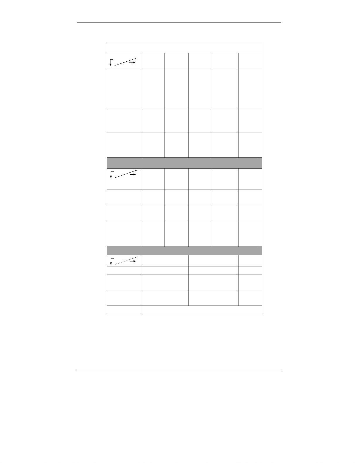
Overview MultiVOIP User Guide
MultiVOIP Product Family
MVP-
2410
Description
Model
Function T1
digital
VOIP
unit
Capacity 24
channels
Chassis/
Mounting
19” 1U
rack
mount
MVP
24-48
T1
digital
VOIP
add-on
card
24
added
channels
circuit
card
only
Description
Model
Function analog
Capacity 8
Chassis/
Mounting
MVP
810
voip
channels
19” 1U
rack
mount
MVP
428
add-on
card
4 added
channels
circuit
card
only
MVP
410
analog
voip
4
channels
19” 1U
rack
mount
Description
Model
MVP810ST MVP410ST
Function ISDN-BRI voip ISDN-BRI voip
Capacity 4 ISDN lines
(8 B-channels)
Chassis/
19” 1U rack mount 19” 1U rack mount
2 ISDN lines
(4 B-channels)
Mounting
1. “BRI” means Basic Rate Interface.
E1
digital
VOIP
unit
channels
19” 1U
rack
mount
MVP
210
analog
voip
Table
top
MVP
3010
30
2
channels
E1
digital
VOIP
add-on
card
30
added
channels
circuit
card
only
MVP130/
130FXS
analog
voip
1
channel
table
top
MVP
30-60
8
Page 9
MultiVOIP User Guide Overview
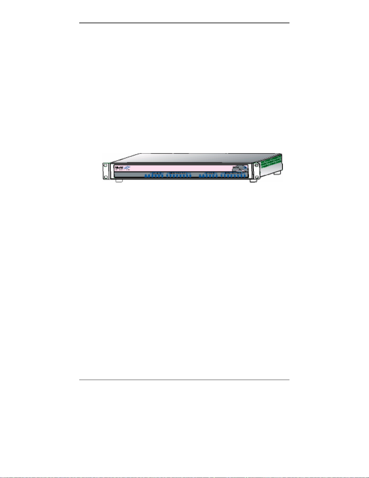
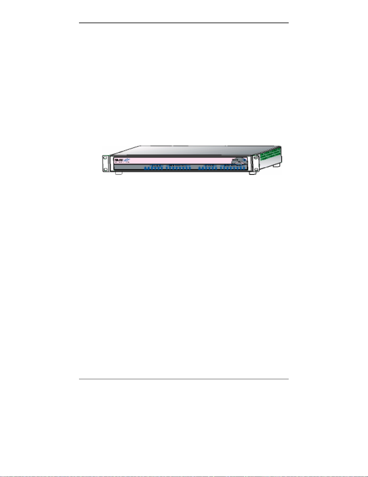
Introduction to TI MultiVOIPs (MVP2410 &
MVP24-48)
We proudly present MultiTech’s T1 Digital Multi-VOIP products.
The MVP2410 is a rack-mount model; and the MVP24-48 is an add-on
expansion card that doubles the capacity of the MVP2410 without
adding another chassis. These voice-over-IP products have fax
capabilities. These models adhere to the North American standard of
T1 trunk telephony using digital 24-channel time-division multiplexing,
which allows 24 phone conversations to occur on the T1 line
simultaneously. They can also accommodate T1 lines of the ISDN
Primary Rate Interface type (ISDN-PRI).
Figure 1-1. MultiVOIP MVP2410 LEDs
Scale-ability. The MVP2410 is tailored to companies needing more
than a few voice-over-IP lines, but not needing carrier-class equipment.
When expansion is needed, the MVP2410 can be field-upgraded into a
dual T1 unit by installing the MVP24-48 kit, which is essentially a
second MultiVOIP motherboard that fits in an open expansion-card slot
in the MVP2410. The upgraded dual unit then accommodates two T1
lines.
T1 VOIP Traffic. The MVP2410 accepts its outbound traffic from a T1
trunk that’s connected to either a PBX or to a telco/carrier. The
MVP2410 transforms the telephony signals into IP packets for
transmission on LANs, WANs, or the Internet. Inbound IP data traffic
is converted to telephony data and signaling.
When connected to PBX. When connected to a PBX, the MVP2410
creates a network node served by 10/100-Base T connections. Local
PBX phone extensions gain toll-free access to all phone stations directly
connected to the VOIP network. Phone extensions at any VOIP location
also gain toll-free access to the entire local public-switched telephone
network (PSTN) at every other VOIP location in the system.
When connected to PSTN. When the T1 line(s) connected to the
MVP2410 are connected directly to the PSTN, the unit becomes a Pointof-Presence server dedicated to local calls off-net.
9
Page 10

Overview MultiVOIP User Guide
H.323, SIP & SPP. Being H.323 compatible, the MVP2410 can place
calls to telephone equipment at remote IP network locations that also
contain H.323 compatible voice-over-IP gateways. It will interface with
H.323 software and H.323 gatekeeper units. H.323 specifications also
bring to voip telephony many special features common to conventional
telephony. H.323 features of this kind that have been implemented into
the MultiVOIP include Call Hold, Call Waiting, Call Name
Identification, Call Forwarding (from the H.450 standard), and Call
Transfer (H.450.2 from H.323 Version 2). The fourth version of the
H.323 standard improves system resource usage (esp. logical port or
socket usage) by handling call signaling more compactly and allowing
use of the low-overhead UDP protocol instead of the error-correcting
TCP protocol where possible.
The MultiVOIP is also SIP-compatible. (“SIP” means Session Initiation
Protocol.) However, H.450 Supplementary Services features can be
used under H.323 only and not under SIP.
SPP (Single-Port Protocol) is a non-standard protocol developed by
Multi-Tech. SPP is not compatible with the “Proprietary” protocol used
in Multi-Tech’s earlier generation of voip gateways. SPP offers
advantages in certain situations, especially when firewalls are used and
when dynamic IP address assignment is needed. However, when SPP
is used, certain features of SIP and H.323 will not be available and SPP
will not inter-operate with voip systems using H.323 or SIP.
Data Compression & Quality of Service. The MultiVOIP MVP2410
comes equipped with a variety of data compression capabilities,
including G.723, G.729, and G.711 and features DiffServ quality-ofservice (QoS) capabilities.
VOIP Functions. The MultiVOIP MVP2410 gateway performs four
basic functions: (a) it converts a dialed number into an IP address, (b) it
sends voice over the data network, (c) it establishes a connection with
another VOIP gateway at a remote site, and (d) it receives voice over
the data network. Voice is handled as IP packets with a variety of
compression options. Each T1 connection to the MultiVOIP provides 24
time-slot channels to connect to the telco or to serve phone or fax
stations connected to a PBX.
Ports. The MVP2410 has one 10/100 Mbps Ethernet LAN interface and
one Command port for configuration. An MVP2410 upgraded with the
MVP24-48 kit will have two Ethernet LAN interfaces and two
Command ports.
PSTN Failover Feature. The MultiVOIP can be programmed to divert
calls to the PSTN temporarily in case the IP network fails.
10
Page 11

MultiVOIP User Guide Overview
RADIUS Support. Inter-operation with a RADIUS server allows for
call accounting (especially for billing) on a voip system. The MultiVOIP
supports inter-operation with RADIUS servers for the RADIUS
accounting function (but not the RADIUS authentication function).
STUN Support. The STUN protocol (Simple Traversal of UDP through
NATs (Network Address Translation)) assists with the packet routing
functions of devices behind NAT firewalls or routers. The MultiVOIP
supports inter-operation with STUN servers and NATs (SIP based
environment only).
Gatekeeper. T1 voip systems can have gatekeeper functionality by
adding, as an endpoint, a Multi-Tech standalone gatekeeper (special
software residing in separate hardware). Gatekeepers are optional but
useful within voip systems. The gatekeeper acts as the ‘clearinghouse’
for all calls within its zone. MultiTech’s stand-alone gatekeeper
software performs all of the standard gatekeepers functions (address
translation, admission control, and bandwidth control) and also
supports many valuable optional functions (call control signaling, call
authorization, bandwidth management, and call management).
Management. Configuration and system management can be done
locally with the MultiVOIP configuration software. After an IP address
has been assigned locally, other configuration can be done remotely
using the MultiVOIP web browser GUI. Remote system management
can be done with the MultiVoipManager SNMP software or via the
MultiVOIP web browser GUI. All of these control software packages
are included on the Product CD.
11
Page 12
Overview MultiVOIP User Guide
While the web GUI’s appearance differs slightly, its content and
organization are essentially the same as that of the Windows GUI
(except for logging).
12
Page 13

MultiVOIP User Guide Overview
The primary advantage of the web GUI is remote access for control and
configuration. The controller PC and the MultiVOIP unit itself must
both be connected to the same IP network and their IP addresses must
be known.
Once you’ve begun using the web browser GUI, you can go back to the
MultiVOIP Windows GUI at any time. However, you must log out of
the web browser GUI before using the MultiVOIP Windows GUI.
13
Page 14
Overview MultiVOIP User Guide
Logging of System Events. MultiTech has built SysLog Server
functionality into the software of the MultiVOIP units. SysLog is a de
facto standard for logging events in network communication systems.
The SysLog Server resides in the MultiVOIP unit itself. To implement
this functionality, you will need a SysLog client program (sometimes
referred to as a “daemon”). SysLog client programs, both paid and
freeware, can be obtained from Kiwi Enterprises, among other firms.
See www.kiwisyslog.com
. SysLog client programs essentially give you
a means of structuring console messages for convenience and ease of
use.
MultiTech Systems does not endorse any particular SysLog client
program. SysLog client programs by any qualified provider should
suffice for use with MultiVOIP units. Kiwi’s brief description of their
SysLog program indicates the typical scope of such programs. “Kiwi
Syslog Daemon is a freeware Syslog Daemon for the Windows
platform. It receives, logs, displays and forwards Syslog messages from
hosts such as routers, switches, Unix hosts and any other syslog
enabled device. There are many customizable options available.”
14
Page 15

MultiVOIP User Guide Overview
Supplementary Telephony Services. The H.450 standard (an addition
to H.323) brings to voip telephony more of the premium features found
in PSTN and PBX telephony. MultiVOIP units offer five of these H.450
features: Call Transfer, Call Hold, Call Waiting, Call Name
Identification (not the same as Caller ID), and Call Forwarding. (The
first four features are found in the “Supplementary Services” window;
the fifth, Call Forwarding, appears in the Add/Edit Inbound
phonebook screen.) Note that the first three features are closely related.
All of these H.450 features are supported for H.323 operation only; they
are not supported for SIP or SPP.
T1 Front Panel LEDs
The MVP2410 and MVP24-48 both use a common main circuit board or
motherboard. Consequently the LED indicators are the same for both.
Active LEDs. The MVP2410 front panel has two sets of identical LEDs.
In the MVP2410 as shipped (that is, without an expansion card), the
left-hand set of LEDs is functional whereas the right-hand set is not.
When the MVP2410 has been upgraded with an MVP24-48 kit, the
right-hand set of LEDs will also become active.
Figure 1-2: MVP2410 LEDs
T1 LED Descriptions. The descriptions below apply to the digital T1
MultiVOIP units. The MVP2410 has four sets of LEDs plus a lone LED
at its far right end. As viewed from the front of the MVP2410, it is the
two left groups that are active and present feedback about the operation
of the unit. If an MVP24-48 expansion card is added to the MVP2410,
the two LED groups on the right become operational with respect to the
second T1 connection.
15
Page 16

Overview MultiVOIP User Guide
MVP2410 Front Panel LED Definitions
LED NAME DESCRIPTION
Power Indicates presence of power.
Boot
After power up, the Boot LED will be on for about 10
seconds while the MVP2410 is booting.
FDX Full-Duplex & Collision LED. This LED indicates
whether the Ethernet connection is half-duplex or fullduplex (FDX) and, in half-duplex mode, indicates
occurrence of data collisions. LED is on constantly for
full-duplex mode; LED is off constantly for half-duplex
mode. When operating in half-duplex mode, the LED
will flash during data collisions.
LNK Link/Activity LED. This LED is lit if Ethernet
connection has been made. It is off when the link is
down (i.e., when no Ethernet connection exists). While
link is up, this LED will flash off to indicate data
activity.
T1 When lit, indicates presence of T1 connection.
E1 E1. Not supported.
PRI PRI. On if T1 line is of ISDN-Primary-Rate type.
ONL Online. This LED is on when frame synchroni-
zation has been established on the T1/E1 link.
IC IC LED is on when Internal Clocking is selected in
T1/E1 configuration.
LC Indicates Loss of Carrier.
LS Indicates Loss of Signal.
Test For testing purposes only.
16
Page 17
MultiVOIP User Guide Overview
Introduction to EI MultiVOIPs
(MVP3010 & MVP30-60)
We proudly present MultiTech’s E1 Digital Multi-VOIP products. The
MVP3010 is a rack-mount model and the MVP30-60 is an add-on
expansion card that doubles the capacity of the MVP3010 without
adding another chassis. All of these voice-over-IP products have fax
capabilities. All adhere to the European standard of E1 trunk telephony
using digital 30-channel time-division multiplexing, which allows 30
phone conversations to occur on the E1 line simultaneously. All can
also accommodate E1 lines of the ISDN Primary Rate Interface type
(ISDN-PRI).
Figure 1-3. MultiVOIP MVP3010 Chassis
Scale-ability. The MVP3010 is tailored to companies needing more
than a few voice-over-IP lines, but not needing carrier-class equipment.
When expansion is needed, the MVP3010 can be field-upgraded into a
dual E1 unit by installing the MVP30-60 kit, which is essentially a
second MultiVOIP motherboard that fits into an open expansion-card
slot in the MVP3010. The upgraded dual unit then accommodates two
E1 lines.
E1 VOIP Traffic. The MVP3010 accepts its outbound traffic from an E1
trunk that’s connected to either a PBX or to a telco/carrier. The
MVP3010 transforms the telephony signals into IP packets for
transmission on LANs, WANs, or the Internet. Inbound IP data traffic
is converted to telephony data and signaling.
When connected to PBX. When connected to a PBX, the MVP3010
creates a network node served by 10/100-Base T connections. Local
PBX phone extensions gain toll-free access to all phone stations directly
connected to the VOIP network. Phone extensions at any VOIP location
also gain local-rate access to the entire local public-switched telephone
network (PSTN) at every other VOIP location in the system.
When connected to PSTN. When the E1 line(s) connected to the
MVP3010 are connected directly to the PSTN, the unit becomes a Pointof-Presence server dedicated to local calls off-net.
17
Page 18

Overview MultiVOIP User Guide
H. 323, SIP, & SPP. Being H.323 compatible, the MVP3010 can place
calls to telephone equipment at remote IP network locations that also
contain H.323 compatible voice-over-IP gateways. It will interface with
H.323 software and H.323 gatekeeper units. H.323 specifications also
bring to voip telephony many special features common to conventional
telephony. H.323 features of this kind that have been implemented into
the MultiVOIP include Call Hold, Call Waiting, Call Identification, Call
Forwarding (from the H.450 standard), and Call Transfer (H.450.2 from
H.323 Version 2). The fourth version of the H.323 standard improves
system resource usage (esp. logical port or socket usage) by handling
call signaling more compactly and allowing use of the low-overhead
UDP protocol instead of the error-correcting TCP protocol where
possible.
The MultiVOIP is also SIP-compatible. (“SIP” means Session Initiation
Protocol.) However, H.450 Supplementary Services features can be
used under H.323 only and not under SIP.
SPP (Single-Port Protocol) is a non-standard protocol developed by
Multi-Tech. SPP is not compatible with the “Proprietary” protocol used
in Multi-Tech’s earlier generation of voip gateways. SPP offers
advantages in certain situations, especially when firewalls are used and
when dynamic IP address assignment is needed. However, when SPP
is used, certain features of SIP and H.323 will not be available and SPP
will not inter-operate with voip systems using H.323 or SIP.
Data Compression & Quality of Service. The MultiVOIP3010 comes
equipped with a variety of data compression capabilities, including
G.723, G.729, and G.711 and features DiffServ quality-of-service (QoS)
capabilities.
VOIP Functions. The MultiVOIP MVP3010 gateway performs four
basic functions: (a) it converts a dialed number into an IP address, (b) it
sends voice over the data network, (c) it establishes a connection with
another VOIP gateway at a remote site, and (d) it receives voice over
the data network. Voice is handled as IP packets with a variety of
compression options. Each E1 connection to the MultiVOIP provides 30
time-slot channels to connect to the telco or to serve phone or fax
stations connected to a PBX.
Ports. The MVP3010 also has a 10/100 Mbps Ethernet LAN interface,
and a Command port for configuration. An MVP3010 upgraded with
the MVP30-60 kit will have two Ethernet LAN interfaces and two
Command ports.
PSTN Failover Feature. The MultiVOIP can be programmed to divert
calls to the PSTN temporarily in case the IP network fails.
RADIUS Support. Inter-operation with a RADIUS server allows for
call accounting (especially for billing) on a voip system. The MultiVOIP
18
Page 19

MultiVOIP User Guide Overview
supports inter-operation with RADIUS servers for the RADIUS
accounting function (but not the RADIUS authentication function).
STUN Support. The STUN protocol (Simple Traversal of UDP through
NATs (Network Address Translation)) assists with the packet routing
functions of devices behind NAT firewalls or routers. The MultiVOIP
supports inter-operation with STUN servers and NATs (SIP based
environment only).
Gatekeeper. E1 voip systems can have gatekeeper functionality by
adding, as an endpoint, a Multi-Tech standalone gatekeeper (special
software residing in separate hardware). Gatekeepers are optional but
useful within voip systems. The gatekeeper acts as the ‘clearinghouse’
for all calls within its zone. MultiTech’s stand-alone gatekeeper
software performs all of the standard gatekeepers functions (address
translation, admission control, bandwidth control, and zone
management) and also supports many valuable optional functions (call
control signaling, call authorization, and bandwidth management).
Management. Configuration and system management can be done
locally with the MultiVOIP configuration software. After an IP address
has been assigned locally, other configuration can be done remotely
using the MultiVOIP web browser GUI. Remote system management
can be done with the MultiVoipManager SNMP software or via the
MultiVOIP web browser GUI. All of these control software packages
are included on the Product CD.
19
Page 20
Overview MultiVOIP User Guide
While the web GUI’s appearance differs slightly, its content and
organization are essentially the same as that of the Windows GUI
(except for logging).
20
Page 21
MultiVOIP User Guide Overview
The primary advantage of the web GUI is remote access for control and
configuration. The controller PC and the MultiVOIP unit itself must
both be connected to the same IP network and their IP addresses must
be known.
Once you’ve begun using the web browser GUI, you can go back to the
MultiVOIP Windows GUI at any time. However, you must log out of
the web browser GUI before using the MultiVOIP Windows GUI.
21
Page 22
Overview MultiVOIP User Guide
Logging of System Events. MultiTech has built SysLog Server
functionality into the software of the MultiVOIP units. SysLog is a de
facto standard for logging events in network communication systems.
The SysLog Server resides in the MultiVOIP unit itself. To implement
this functionality, you will need a SysLog client program (sometimes
referred to as a “daemon”). SysLog client programs, both paid and
freeware, can be obtained from Kiwi Enterprises, among other firms.
See www.kiwisyslog.com
. SysLog client programs essentially give you
a means of structuring console messages for convenience and ease of
use.
MultiTech Systems does not endorse any particular SysLog client
program. SysLog client programs by any qualified provider should
suffice for use with MultiVOIP units. Kiwi’s brief description of their
SysLog program indicates the typical scope of such programs. “Kiwi
Syslog Daemon is a freeware Syslog Daemon for the Windows
platform. It receives, logs, displays and forwards Syslog messages from
hosts such as routers, switches, Unix hosts and any other syslog
enabled device. There are many customizable options available.”
22
Page 23
MultiVOIP User Guide Overview
Supplementary Telephony Services. The H.450 standard (an addition
to H.323) brings to voip telephony more of the premium features found
in PSTN and PBX telephony. MultiVOIP units offer five of these H.450
features: Call Transfer, Call Hold, Call Waiting, Call Name
Identification (not the same as Caller ID), and Call Forwarding. (The
first four features are found in the “Supplementary Services” window;
the fifth, Call Forwarding, appears in the Add/Edit Inbound
phonebook screen.) Note that the first three features are closely related.
All of these H.450 features are supported for H.323 operation only; they
are not supported for SIP or SPP.
E1 Front Panel LEDs
Because the MVP3010 and MVP30-60 both use a common main circuit
card or motherboard, the LED indicators are the same for both.
Figure 1-4: MVP3010 LEDs
Active LEDs. The MVP3010 front panel has two sets of identical LEDs.
In the MVP3010 as shipped (that is, without an expansion card), the
left-hand set of LEDs is functional whereas the right-hand set is not.
When the MVP3010 has been upgraded with an MVP30-60 kit, the
right-hand set of LEDs will also become active.
23
Page 24

Overview MultiVOIP User Guide
E1 LED Descriptions
MVP3010 Front Panel LED Definitions
LED NAME DESCRIPTION
Power Indicates presence of power.
Boot After power up, the Boot LED will be on for
about 10 seconds while the MVP3010 is booting.
FDX Full-Duplex & Collision LED. This LED indicates
whether the Ethernet connection is half-duplex or fullduplex (FDX) and, in half-duplex mode, indicates
occurrence of data collisions. LED is on constantly for
full-duplex mode; LED is off constantly for halfduplex mode. When operating in half-duplex mode,
the LED will flash during data collisions.
LNK Link/Activity LED. This LED is lit if Ethernet
connection has been made. It is off when the link is
down (i.e., when no Ethernet connection exists).
While link is up, this LED will flash off to indicate data
activity.
T1 T1. Not supported.
E1 E1. When lit, indicates presence of E1
connection.
PRI PRI. On if E1 line is of ISDN-Primary-Rate type.
ONL Online. This LED is on when frame
synchronization has been established on the
T1/E1 link.
IC IC LED is on when Internal Clocking is selected
in T1/E1 configuration.
LC Indicates Loss of Carrier.
LS Indicates Loss of Signal.
Test For testing purposes only.
24
Page 25

MultiVOIP User Guide Overview
Specifications
Specs for Digital T1 MultiVOIP Units
Digital T1 MultiVOIP Specifications
Parameter
……/Model
Operating
Voltage/Current
Mains
Frequencies
Power
Consumption
Mechanical
Dimensions
Weight
MVP-2410
100-240 VAC
1.2 - 0.6 A
50/60 Hz 50/60 Hz
17 watts 27 watts
1.75”H x
17.4”W x
8.75”D
4.5cm H x
44.2 cm W x
22.2 cm D
7.1 lbs.
(3.2 kg)
MVP-2410
w/ MVP24-48
Expansion
Card
100-240 VAC
1.2 - 0.6 A
1.75”H x
17.4”W x
8.75”D
4.5cm H x
44.2 cm W x
22.2 cm D
7.5 lbs.
(3.4 kg)
25
Page 26

Overview MultiVOIP User Guide
Specs for Digital E1 MultiVOIP Units
Digital E1 MultiVOIP Specifications
Parameter
……/Model
Operating
Voltage/Current
Mains
Frequencies
Power
Consumption
Mechanical
Dimensions
Weight
MVP-3010 MVP-3010
w/ MVP30-60
Expansion
Card
100-240 VAC
1.2 - 0.6 A
100-240 VAC
1.2 - 0.6 A
50/60 Hz 50/60 Hz
17 watts 27 watts
1.75”H x
17.4”W x
8.75”D
4.5cm H x
44.2 cm W x
22.2 cm D
7.1 lbs.
(3.2 kg)
1.75”H x
17.4”W x
8.75”D
4.5cm H x
44.2 cm W x
22.2 cm D
7.5 lbs.
(3.4 kg)
26
Page 27

MultiVOIP User Guide Overview
Installation at a Glance
The basic steps of installing your MultiVOIP network involve
unpacking the units, connecting the cables, and configuring the units
using management software (MultiVOIP Configuration software) and
confirming connectivity with another voip site. This process results in a
fully functional Voice-Over-IP network.
Related Documentation
The MultiVOIP User Guide (the document you are now reading) comes
in electronic form and is included on your system CD. It presents indepth information on the features and functionality of Multi-Tech’s
MultiVOIP Product Family.
The CD media is produced using Adobe Acrobat
printing the user guide. To view or print your copy of a user guide,
load Acrobat Reader
on the MultiVOIP CD and is also a free download from Adobe’s Web
Site:
TM
on your system. The Acrobat Reader is included
TM
for viewing and
www.adobe.com/prodindex/acrobat/readstep.html
This MultiVOIP User Guide is also available on Multi-Tech’s Web site
at:
http://www.multitech.com
Viewing and printing a user guide from the Web also requires that you
have the Acrobat Reader loaded on your system. To select the MultiVOIP
User Guide from the Multi-Tech Systems home page, click Documents and then click
MultiVOIP Family in the product list drop-down window. All documents for this
MultiVOIP Product Family will be displayed. You can then choose User Guide
(MultiVOIP Product Family) to view or download the .pdf file.
Entries (organized by model number) in the “knowledge base” and
‘troubleshooting resolutions’ sections of the MultiTech web site (found
under “Support”) constitute another source of help for problems
encountered in the field.
27
Page 28

Chapter 2: Quick Start Instructions
28
Page 29

MultiVOIP User Guide Quick Start Instructions
The Quick Start Guide is a separate manual with streamlined
instructions to get the MultiVOIP up and running quickly. These startup instructions include assistance on setting up the MultiVOIP’s
Inbound and Outbound Phonebooks. These sections of the Quick Start
Guide may be particularly useful for phonebook configuration:
Phonebook Starter Configuration
Phonebook Tips
Phonebook Example (One Common Situation)
The Quick Start Guide also contains a “Phonebook Worksheet” section.
You may want to print out several worksheet copies. Paper copies can
be very helpful in comparing phonebooks at multiple sites at a glance.
This will assist you in making the phonebooks clear and consistent and
will reduce ‘surfing’ between screens on the configuration program.
A printed Quick Start Guide is shipped with the MultiVOIP and an
electronic copy is included on the Product CD.
29
Page 30

Mechanical Installation & Cabling MultiVOIP User Guide
Chapter 3: Mechanical Installation
and Cabling
30
Page 31

MultiVOIP User Guide Mechanical Installation & Cabling
Introduction
When the MVP2410 or MVP3010 unit is to be installed into a rack, two
able-bodied persons should participate.
Please read the safety notices before beginning installation.
Safety Warnings
Lithium Battery Caution
A lithium battery on the voice/fax channel board provides backup
power for the timekeeping capability. The battery has an estimated life
expectancy of ten years.
When the battery starts to weaken, the date and time may be incorrect.
If the battery fails, the board must be sent back to Multi-Tech Systems
for battery replacement.
Warning: There is danger of explosion if the battery is incorrectly
replaced.
Safety Warnings Telecom
1. Never install telephone wiring during a lightning storm.
2. Never install a telephone jack in wet locations unless the jack is
specifically designed for wet locations.
3. This product is to be used with UL and UL listed computers.
4. Never touch uninsulated telephone wires or terminals unless the
telephone line has been disconnected at the network interface.
5. Use caution when installing or modifying telephone lines.
6. Avoid using a telephone (other than a cordless type) during an
electrical storm. There may be a remote risk of electrical shock from
lightning.
7. Do not use a telephone in the vicinity of a gas leak.
8. To reduce the risk of fire, use only a UL-listed 26 AWG or larger
telecommunication line cord.
31
Page 32

Mechanical Installation & Cabling MultiVOIP User Guide
Unpacking Your MultiVOIP
When unpacking your MultiVOIP, check to see that all of the items
shown are included in the box. If any box contents are missing, contact
MultiTech Tech Support at 1-800-972-2439.
Unpacking the MVP2410/3010
Figure 3-1: Unpacking the MVP2410/3010
32
Page 33

MultiVOIP User Guide Mechanical Installation & Cabling
Rack Mounting Instructions
The MultiVOIPs can be mounted in an industry-standard EIA 19-inch
rack enclosure, as shown in Figure 3-2.
Figure 3-2: Rack-Mounting
33
Page 34

Mechanical Installation & Cabling MultiVOIP User Guide
Safety Recommendations for Rack Installations
Ensure proper installation of the unit in a closed or multi-unit enclosure
by following the recommended installation as defined by the enclosure
manufacturer. Do not place the unit directly on top of other equipment
or place other equipment directly on top of the unit. If installing the
unit in a closed or multi-unit enclosure, ensure adequate airflow within
the rack so that the maximum recommended ambient temperature is
not exceeded. Ensure that the unit is properly connected to earth
ground by verifying that it is reliably grounded when mounted within
a rack. If a power strip is used, ensure that the power strip provides
adequate grounding of the attached apparatus.
When mounting the equipment in the rack, make sure mechanical
loading is even to avoid a hazardous condition, such as loading heavy
equipment in rack unevenly. The rack used should safely support the
combined weight of all the equipment it supports.
Ensure that the mains supply circuit is capable of handling the load of
the equipment. See the power label on the equipment for load
requirements (full specifications for MultiVOIP models are presented in
chapter 1 of this manual).
Maximum ambient temperature for the unit is 60 degrees Celsius (140
degrees Fahrenheit) at 20-90% non-condensing relative humidity. This
equipment should only be installed by properly qualified service
personnel. Only connect like circuits. In other words, connect SELV
(Secondary Extra Low Voltage) circuits to SELV circuits and TN
(Telecommunications Network) circuits to TN circuits.
34
Page 35

MultiVOIP User Guide Mechanical Installation & Cabling
19-Inch Rack Enclosure Mounting Procedure
Attaching the MultiVOIP to a rack-rail of an EIA 19-inch rack enclosure
will certainly require two persons. Essentially, the technicians must
attach the brackets to the MultiVOIP chassis with the screws provided,
as shown in Figure 3-3, and then secure unit to rack rails by the
brackets, as shown in Figure 3-4. Because equipment racks vary, screws
for rack-rail mounting are not provided. Follow the instructions of the
rack manufacturer and use screws that fit.
1. Position the right rack-mounting bracket on the MultiVOIP
using the two vertical mounting screw holes.
2. Secure the bracket to the MultiVOIP using the two screws
provided.
3. Position the left rack-mounting bracket on the MultiVOIP
using the two vertical mounting screw holes.
4. Secure the bracket to the MultiVOIP using the two screws
provided.
5. Remove feet (4) from the MultiVOIP unit.
6. Mount the MultiVOIP in the rack enclosure per the rack
manufacture’s mounting procedure.
x
x
Figure 3-3: Bracket Attachment for Rack Mounting
Figure 3-4: Attaching MultiVOIP to Rack Rail
35
Page 36

Mechanical Installation & Cabling MultiVOIP User Guide
Cabling
Cabling Procedure
Cabling your MultiVOIP entails making the proper connections for
power, command port, phone system (T1/E1 line connected to PBX or
telco office), and Ethernet network. Figure 3-5 shows the back panel
connectors and the associated cable connections. The following
procedure details the steps necessary for cabling your MultiVOIP.
1. Connect the power cord to a live AC outlet, then connect it to the
MultiVOIP’s power receptacle shown at top right in Figure 3-5.
DIGITAL VOICE
ETHERNET COMMAND
10 BASET
TRUNK
RS232
DIGITAL VOICE
T1
COMMAND
MODEM
ETHERNET COMMAND
Command Port Connection
PBX
PSTN
Telephony Connection
Figure 3-5. Cabling for MVP2410/3010
2. Connect the MultiVOIP to the PC (the computer that will hold the
MultiVOIP software) using the RJ-45 to DB9 (female) cable provided
with your unit. Plug the RJ-45 end of the cable into the Command
port of the MultiVOIP and connect the other end (the DB9 connector)
to the PC serial port you are using (typically COM1 or COM2). See
Figure 3-5.
3. Connect a network cable to the Ethernet connector on the back of the
MultiVOIP. Connect the other end of the cable to your network.
Hub
Network Connection
36
Page 37

MultiVOIP User Guide Mechanical Installation & Cabling
4. If you intend to configure the MultiVOIP remotely using the
MultiVOIP Windows GUI, connect an RJ-11 phone cable between the
Command Modem connector (at the rear of the MultiVOIP) and a
receptacle served by a telco POTS line. See Figure 3-6.
The Command Modem is built into the MultiVOIP unit. To configure
the MultiVOIP remotely using its Windows GUI, you must call into
the MultiVOIP’s Command Modem. Once a connection is made, the
configuration process is identical to local configuration with the
Windows GUI.
DIGITAL VOICE
COMMAND
MODEM
DIGITAL VOIC E
TRUNK
ETHERNET COMMAND
ETHERNET COMMAND
10 BASET
RS232
Grounding Screw
Telco POTS Line
Figure 3-6. MVP-2410/3010 Voip Connections
for GND & Remote Config Modem
5. Ensure that the unit is properly connected to earth ground by
verifying that it is reliably grounded when mounted within a rack.
This can be accomplished by connecting a grounding wire between
the chassis grounding screw (see Figure 3-6) and a metallic object that
will provide an electrical ground.
6. Turn on power to the MultiVOIP by setting the power switch on the
right side panel to the ON position. Wait for the Boot LED on the
MultiVOIP to go off before proceeding. This may take a couple of
minutes.
Proceed to Chapter 4 “Software Installation.”
37
Page 38

Technical Configuration (T1/E1) MultiVOIP User Guide
Chapter 4: Software Installation
38
Page 39

MultiVOIP User Guide Mechanical Installation & Cabling
Introduction
Configuring software for your MultiVOIP entails three tasks:
(1) loading the software onto the PC (this is “Software Installation and
is discussed in this chapter),
(2) setting values for telephony and IP parameters that will fit your
system (this is “Technical Configuration” and it is discussed in Chapter
5), and
(3) establishing “phonebooks” that contain the various dialing patterns
for VOIP calls made to different locations (this is “Phonebook
Configuration” and it is discussed in Chapter 6 for North American
(T1) telephony standards and in Chapter 7 for European (E1) telephony
standards.
Loading MultiVOIP Software onto the PC
The software loading procedure does not present every screen or option
in the loading process. It is assumed that someone with a thorough
knowledge of Windows and the software loading process is performing
the installation.
The MultiVOIP software and User Guide are contained on the
MultiVOIP product CD. Because the CD is auto-detectable, it will start
up automatically when you insert it into your CD-ROM drive. When
you have finished loading your MultiVOIP software, you can view and
print the User Guide by clicking on the View Manuals icon.
1. Be sure that your MultiVOIP has been properly cabled and that the
power is turned on.
39
Page 40

Technical Configuration (T1/E1) MultiVOIP User Guide
2. Insert the MultiVOIP CD into your CD-ROM drive. The CD should
start automatically. It may take 10 to 20 seconds for the Multi-Tech
CD installation window to display.
If the Multi-Tech Installation CD window does not display
automatically, click My Computer, then right click the CD ROM
drive icon, click Open, and then click the Autorun icon.
3. When the Multi-Tech Installation CD dialog box appears, click the
Install Software icon.
40
Page 41

MultiVOIP User Guide Mechanical Installation & Cabling
4. A ‘welcome’ screen appears.
Press Enter or click Next to continue.
41
Page 42

Technical Configuration (T1/E1) MultiVOIP User Guide
5. Follow the on-screen instructions to install your MultiVOIP software.
The first screen asks you to choose the folder location of the files of
the MultiVOIP software.
Choose a location and click Next.
42
Page 43

MultiVOIP User Guide Mechanical Installation & Cabling
6. At the next screen, you must select a program folder location for the
MultiVOIP software program icon.
Click Next. Transient progress screens will appear while files are
being copied.
43
Page 44

Technical Configuration (T1/E1) MultiVOIP User Guide
7. On the next screen you can select the COM port that the command
PC will use when communicating with the MultiVoip unit. After
software installation, the COM port can be re-set in the MultiVOIP
Software (from the sidebar menu, select Connection | Settings to
access the COM Port Setup screen or use the keyboard shortcut Ctrl
+ G).
NOTE: If the COM port setting made
here conflicts with the actual COM
port resources available in the
command PC, this error message will
appear when the MultiVOIP program
is launched. If this occurs, you must
reset the COM port.
44
Page 45

MultiVOIP User Guide Mechanical Installation & Cabling
8. A completion screen will appear.
Click Finish.
9. When setup of the MultiVOIP software is complete, you will be
prompted to run the MultiVOIP software to configure the VOIP.
Software installation is complete at this point. You may proceed with
Technical Configuration now or not, at your convenience.
Technical Configuration instructions are in the next chapter of this
manual.
45
Page 46
Technical Configuration (T1/E1) MultiVOIP User Guide
Un-Installing the MultiVOIP Configuration
Software
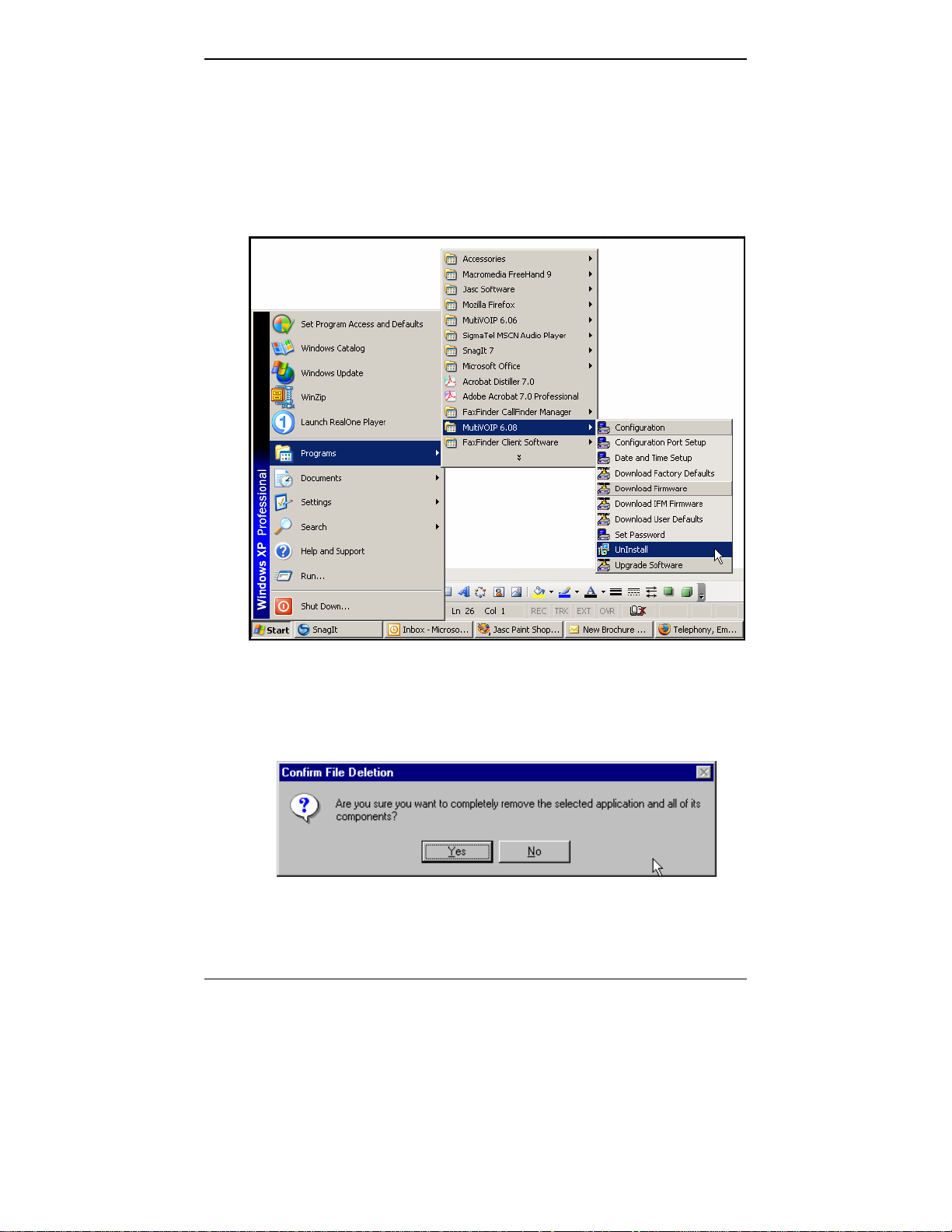
1. To un-install the MultiVOIP configuration software, go to Start |
Programs and locate the entry for the MultiVOIP program. Select
Uninstall.
2. Two confirmation screens will appear. Click Yes and OK when you
are certain you want to continue with the uninstallation process.
46
Page 47

MultiVOIP User Guide Mechanical Installation & Cabling
3. A special warning message similar to that shown below may appear
concerning the MultiVOIP software’s “.bin” file. Click Yes.
47
Page 48

Technical Configuration (T1/E1) MultiVOIP User Guide
4. A completion screen will appear.
Click Finish.
48
Page 49

Chapter 5: Technical Configuration
49
Page 50

Technical Configuration MultiVOIP User Guide
Configuring the MultiVOIP
There are two ways in which the MultiVOIP must be configured before
operation: technical configuration and phonebook configuration.
Technical Configuration. First, the MultiVOIP must be configured to
operate with technical parameter settings that will match the
equipment with which it interfaces. There are eight types of technical
parameters that must be set.
These technical parameters pertain to
(1) its operation in an IP network,
(2) its operation with telephony equipment,
(3) its transmission of voice and fax messages,
(4) its interaction with SNMP (Simple Network Management Protocol)
network management software (MultiVoipManager),
(5) certain telephony attributes that are common to particular nations or
regions,
(6) its operation with a mail server on the same IP network (per SMTP
parameters) such that log reports about VoIP telephone call traffic can
be sent to the administrator by email,
(7) implementing some common premium telephony features (Call
Transfer, Call Hold, Call Waiting, Call ID – “Supplementary Services”),
and
(8) selecting the method by which log reports will be made accessible.
The process of specifying values for the various parameters in these
seven categories is what we call “technical configuration” and it is
described in this chapter.
Phonebook Configuration. The second type of configuration that is
required for the MultiVOIP pertains to the phone number dialing
sequences that it will receive and transmit when handling calls. Dialing
patterns will be affected by both the PBX/telephony equipment and the
other VOIP devices that the MultiVOIP unit interacts with. We call this
“Phonebook Configuration,” and, for analog MultiVOIP units, it is
described in Chapter 6. The Quick Start Guide presents additional
information on phonebook setup.
Local/Remote Configuration. The MultiVOIP must be configured
locally at first (to establish an IP address for the MultiVOIP unit). But
changes to this initial configuration can be done either locally or
remotely.
50
Page 51

MultiVOIP User Guide Technical Configuration
Local configuration is done through a connection between the
“Command” port of the MultiVOIP and the COM port of the computer;
the MultiVOIP configuration program is used.
Remote configuration is done through a connection between the
MultiVOIP’s Ethernet (network) port and a computer connected to the
same network. The computer could be miles or continents away from
the MultiVOIP itself. There are two ways of doing remote
configuration and operation of the MultiVOIP unit: (1) using the
MultiVoipManager SNMP program, or (2) using the MultiVOIP web
browser interface program.
MultiVoipManager. MultiVoipManager is an SNMP agent program
(Simple Network Management Protocol) that extends the capabilities of
the MultiVOIP configuration program: MultiVoipManager allows the
user to manage any number of VOIPs on a network, whereas the
MultiVOIP configuration program can manage only the VOIP to which
it is directly/locally connected. The MultiVoipManager can configure
multiple VOIPs simultaneously, whereas the MultiVOIP configuration
program can configure only one at a time.
MultiVoipManager may (but does not need to) reside on the same PC
as the MultiVOIP configuration program. The MultiVoipManager
program is on the MultiVOIP Product CD. Updates, when applicable,
may be posted at on the MultiTech FTP site. To download, go to
ftp://ftp.multitech.com/MultiVoip/
.
Web Browser Interface. The MultiVOIP web browser GUI gives access
to the same commands and configuration parameters as are available in
the MultiVOIP Windows GUI except for logging functions. When
using the web browser GUI, logging can be done by email (the SMTP
option).
51
Page 52

Technical Configuration MultiVOIP User Guide
Functional Equivalence of Interfaces. The MultiVOIP configuration
program is required to do the initial configuration (that is, setting an IP
address for the MultiVOIP unit) so that the VOIP unit can communicate
with the MultiVoipManager program or with the web browser GUI.
Management of the VOIP after that point can be done from any of these
three programs since they all offer essentially the same functionality.
Functionally, either the MultiVoipManager program or the web
browser GUI can replace the MultiVOIP configuration program after
the initial configuration is complete (with minor exceptions, as noted).
WARNING: Do not attempt to interface the MultiVOIP unit with
two control programs simultaneously (that is, by
accessing the MultiVOIP configuration program via
the Command Port and either the
MultiVoipManager program or the web browser
interface via the Ethernet Port). The results of using
two programs to control a single VOIP
simultaneously would be unpredictable.
52
Page 53

MultiVOIP User Guide Technical Configuration
Local Configuration
This manual primarily describes local configuration with the Windows
GUI. After IP addresses have been set locally using the Windows GUI,
most aspects of configuration (logging functions are an exception) can
be handled through the web browser GUI, as well (see the Operation and
Maintenance chapter of this manual). In most aspects of configuration,
the Windows GUI and web-browser GUI differ only graphically, not
functionally. For information on SNMP remote configuration and
management, see the MultiVoipManager documentation.
Pre-Requisites
To complete the configuration of the
MultiVOIP unit, you must know several
things about the overall system.
Before configuring your MultiVOIP Gateway unit, you must know the
values for several IP and telephone parameters that describe the IP
network system and telephony system (PBX or telco central office
equipment) with which the digital MultiVOIP will interact. If you plan
to receive log reports on phone traffic by email (SMTP), you must
arrange to have an email address assigned to the VOIP unit on the
email server on your IP network. A summary of this configuration
information appears on page 58 (“Config Info CheckList”).
53
Page 54

Technical Configuration MultiVOIP User Guide
IP Parameters
The following parameters must be known about the network (LAN,
WAN, Internet, etc.) to which the MultiVOIP will connect:
Ask your computer network
Ê
administrator.
#
• IP Address
• IP Mask
• Gateway
• Domain Name Server (DNS) Info
• If SIP protocol is used, determine whether or not
802.1p Packet Prioritization will be used.
Write down the values for these IP parameters. You will need to enter
these values in the “IP Parameters” screen in the Configuration section
of the MultiVOIP software. You must have this IP information about
every VOIP in the system.
IP Network Parameters:
Record for each VOIP Site
in System
Info needed to operate:
all MultiVOIP models.
54
Page 55

MultiVOIP User Guide Technical Configuration
T1 Telephony Parameters (for MVP2410)
The following parameters must be known about the PBX or telco
central office equipment to which the T1 MultiVOIP will connect:
T1 Phone Parameters
Ê
Ask phone company or
PBX maintainer.
#
• Which frame format is used?
• Which CAS or PRI protocol is used? ______________
• Clocking: Does the PBX or telco switch use
• Which line coding is used?
Write down the values for these T1 parameters. You will need to enter
these values in the “T1/E1 Parameters” screen in the Configuration
section of the MultiVOIP software.
T1 T elephon y Parameters:
Record for this VOIP Site
internal or external clocking? _________________
Note that the setting used in the voip unit will be the
opposite of the setting used by the telco/PBX.
Info needed to operate:
MVP2410
ESF___ or D4___
AMI___ or B8ZS___
55
Page 56

Technical Configuration MultiVOIP User Guide
E1 Telephony Parameters (for MVP3010)
The following parameters must be known about the PBX or telco
central office equipment to which the E1 MultiVOIP will connect:
E1 Phone Parameters
Ê
Ask phone company or
PBX maintainer.
#
• Which frame format is used?
• Which CAS or PRI protocol is used? ______________
• Clocking: Does the PBX or telco switch use
internal or external clocking? _________________
Note that the setting used in the voip unit will be the
opposite of the setting used by the telco/PBX.
• Which line coding is used?
• Pulse shape level?: (most commonly 0 to 40 meters)
Write down the values for these E1 parameters. You will need to enter
these values in the “T1/E1 Parameters” screen in the Configuration
section of the MultiVOIP software.
E1 Telephony Parameters:
Record fo r this VOIP Site
MultiFrame w/ CRC4 modified_____
Info needed to operate:
MVP3010
Double Frame_____
MultiFrame w/ CRC4_____
AMI___ or HDB3___
56
Page 57

MultiVOIP User Guide Technical Configuration
7
SMTP Parameters (for email call log reporting)
required if log reports of
VOIP call traffic
are to be sent by email
SMTP Parameters
Preparation Task:
Ask Mail Server
administrator to set up
email account (with
password) for the
MultiVOIP unit itself.
Be sure to give a unique
identifier to each
individual MultiVOIP
unit. .
Get the IP address of the
mail server computer, as
well.
Optional
To: I .T. D ep ar tm ent
re: email accoun t for VOIP
voip-unit2@biggytech.com
5
Page 58

Technical Configuration MultiVOIP User Guide
Config Info CheckList
58
Page 59

MultiVOIP User Guide Technical Configuration
Local Configuration Procedure (Summary)
After the MultiVOIP configuration software has been installed in the
‘Command’ PC (which is connected to the MultiVOIP unit), several
steps must be taken to configure the MultiVOIP to function in its
specific setting. Although the summary below includes all of these
steps, some are optional.
1. Check Power and Cabling.
2. Start MultiVOIP Configuration Program.
3. Confirm Connection.
4. Solve Common Connection Problems.
A. Fixing a COM Port Problem.
B. Fixing a Cabling Problem.
5. Familiarize yourself with configuration parameter screens and how
to access them.
6. Set Ethernet/IP Parameters.
7. Set up web browser GUI (optional).
8. Set Voice/Fax Parameters.
9. Set T1/E1 Parameters.
10. Set ISDN Parameters (if applicable).
11. Set Call Signaling parameters. The choice of H.323, SIP, or SPP is
made in the Outbound Phonebook, but details are configured in the
Call Signaling Parameters screen.
12. Set SNMP Parameters (applicable if MultiVoipManager remote
management software is used).
13. Set Regional Parameters (Phone Signaling Tones & Cadences and
setup for built-in Remote Configuration/Command Modem).
13. Set Custom Tones and Cadences (optional).
14. Set SMTP Parameters (applicable if Log Reports are via Email).
15. Set Log Reporting Method (GUI, locally in MultiVOIP
Configuration program; SNMP, remotely in MultiVoipManager
program; or SMTP, via email).
16. Set Supplementary Services Parameters. The Supplementary
Services screen allows voip deployment of features that are normally
found in PBX or PSTN systems (e.g., call transfer and call waiting).
59
Page 60

Technical Configuration MultiVOIP User Guide
17. Set NAT Traversal (STUN) parameters. Optional. Applicable only
under SIP Call Signaling when the UDP transport protocol is used.
18. Set RADIUS parameters. Optional. Used only if system interfaces
with RADIUS server for billing or other accounting functions.
19. Set Baud Rate (of COM port connection to ‘Command’ PC).
20. View System Info screen and set updating interval (optional).
21. Save the MultiVOIP configuration.
22. Create a User Default Configuration (optional).
When technical configuration is complete, you will need to configure
the MultiVOIP’s inbound and outbound phonebooks. This manual has
separate chapters describing T1 Phonebook Configuration for NorthAmerican-influenced telephony settings and E1 Phonebook
Configuration for Euro-influenced telephony settings.
Local Configuration Procedure (Detailed)
You can begin the configuration process as a continuation of the
MultiVOIP software installation. You can establish your configuration
or modify it at any time by launching the MultiVOIP program from the
Windows Start menu.
1. Check Power and Cabling. Be sure the MultiVOIP is turned on and
connected to the computer via the MultiVOIP’s Command Port (DB9
connector at computer’s COM port; RJ45 connector at MultiVOIP).
2. Start MultiVOIP Configuration Program. Launch the MultiVOIP
program from the Windows Start menu (from the folder location
determined during installation).
60
Page 61

MultiVOIP User Guide Technical Configuration
3. Confirm Connection. If the MultiVOIP is set for an available COM
port and is correctly cabled to the PC, the MultiVOIP main screen will
appear. (If the main screen appears grayed out and seems inaccessible,
go to step 4.)
61
Page 62

Technical Configuration MultiVOIP User Guide
In the lower left corner of the screen, the connection status of the
MultiVOIP will be displayed. The messages in the lower left corner
will change as detection occurs. The message “MultiVOIP Found”
confirms that the MultiVOIP is in contact with the MultiVOIP
configuration program. Skip to step 5.
62
Page 63

MultiVOIP User Guide Technical Configuration
4. Solving Common Connection Problems.
A. Fixing a COM Port Problem. If the MultiVOIP main screen appears
but is grayed out and seems inaccessible, the COM port that was
specified for its communication with the PC is unavailable and must
be changed. An error message will appear.
To change the COM port setting, use the COM Port Setup dialog box,
which is accessible via the keyboard shortcut Ctrl + G or by going to
the Connection pull-down menu and choosing “Settings.” In the
“Select Port” field, select a COM port that is available on the PC. (If
no COM ports are currently available, re-allocate COM port resources
in the computer’s MS Windows operating system to make one
available.)
Ctrl + G
63
Page 64

Technical Configuration MultiVOIP User Guide
4B. Fixing a Cabling Problem. If the MultiVOIP cannot be located by
the computer, two error messages will appear (saying “Multi-VOIP
Not Found” and “Phone Database Not Read”).
In this case, the MultiVOIP is simply disconnected from the network.
For instructions on MultiVOIP cable connections, see the Cabling
section of Chapter 3.
5. Configuration Parameter Groups: Getting Familiar, Learning
About Access. The first part of configuration concerns IP parameters,
Voice/FAX parameters, Telephony Interface parameters, SNMP
parameters, Regional parameters, SMTP parameters, Supplementary
Services parameters, Logs, and System Information. In the MultiVOIP
software, these seven types of parameters are grouped together under
“Configuration” and each has its own dialog box for entering values.
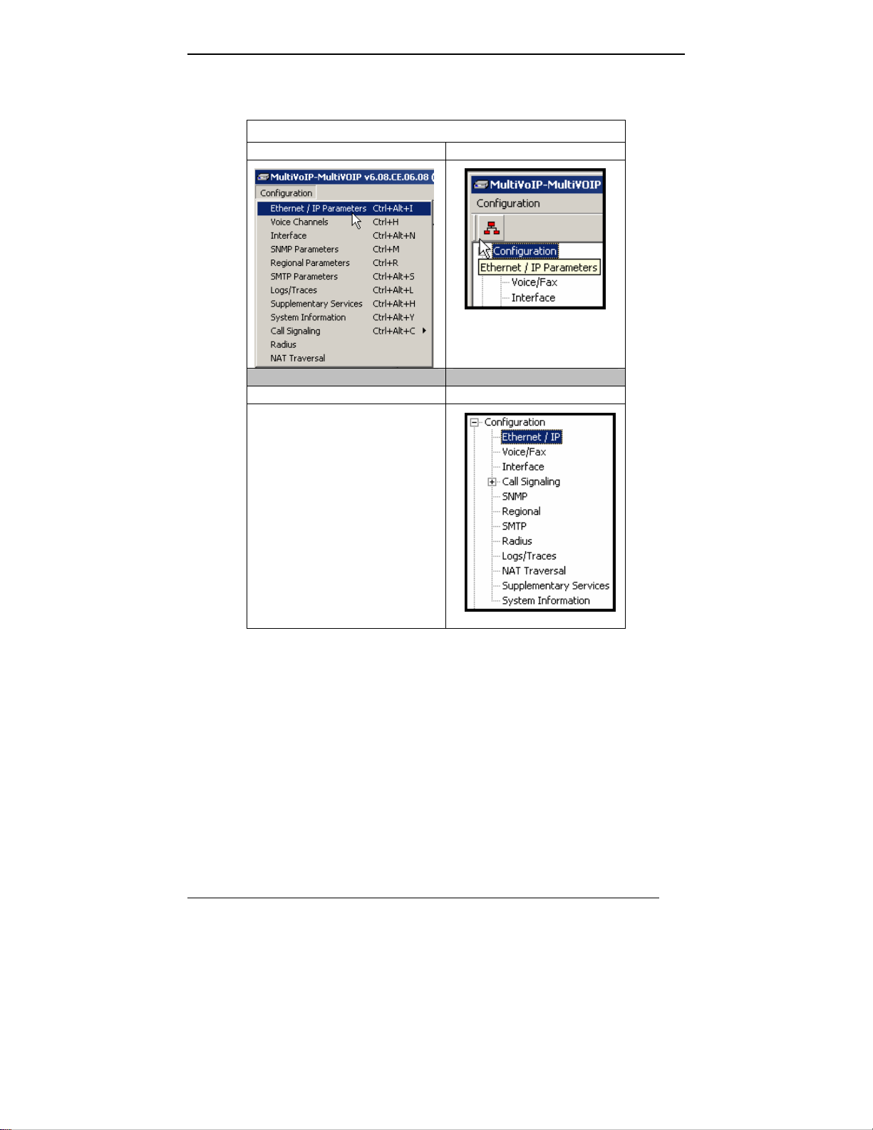
Generally, you can reach the dialog box for these parameter groups in
one of four ways: pulldown menu, toolbar icon, keyboard shortcut, or
sidebar.
64
Page 65
MultiVOIP User Guide Technical Configuration
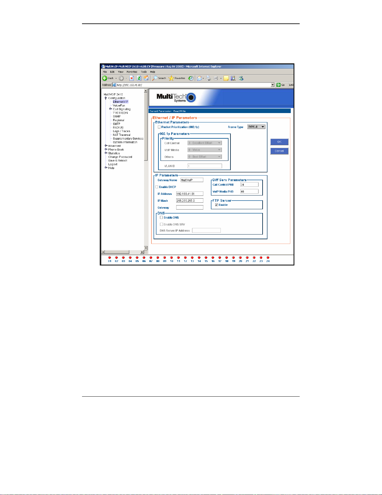
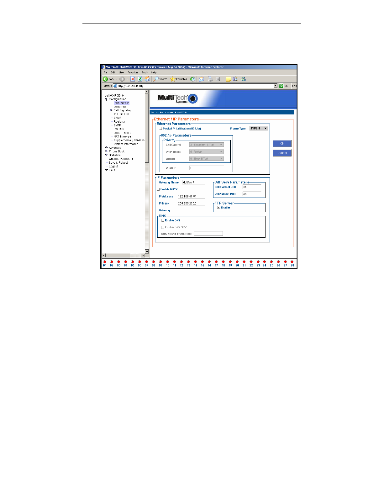
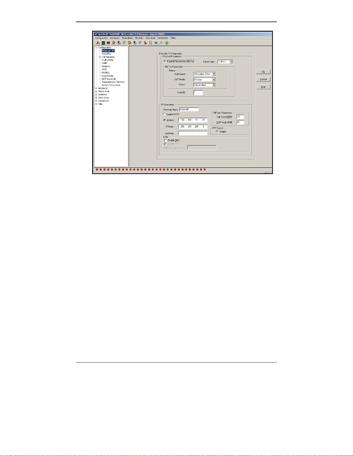
6. Set Ethernet/IP Parameters. This dialog box can be reached by
pulldown menu, toolbar icon, keyboard shortcut, or sidebar.
Accessing “Ethernet/IP Parameters”
Pulldown Icon
Shortcut Sidebar
Ctrl + Alt + I
65
Page 66

Technical Configuration MultiVOIP User Guide
In each field, enter the values that fit your particular network.
66
Page 67

MultiVOIP User Guide Technical Configuration
7
The Ethernet/IP Parameters fields are described in the tables and text
passages below. Note that both DiffServ parameters (Call Control PHB
and VoIP Media PHB) must be set to zero if you enable Packet
Prioritization (802.1p). Nonzero DiffServ values negate the
prioritization scheme.
Ethernet/IP Parameter Definitions (cont’d)
Field Name Values Description
Ethernet Parameters
Packet
Prioritization
(802.1p)
Y/N
Select to activate
prioritization under 802.1p
protocol (described below).
.
Frame Type Type II, SNAP
Must be set to match
network’s frame type.
Default is Type II.
802.1p
A draft standard of the IEEE about data traffic
prioritization on Ethernet networks. The 802.1p
draft is an extension of the 802.1D bridging
standard. 802.1D determines how prioritization
will operate within a MAC-layer bridge for any
kind of media. The 802.1Q draft for virtual local-
area-networks (VLANs) addresses the issue of
prioritization for Ethernet networks in particular.
802.1p enacts this Quality-of-Service feature
using 3 bits. This 3-bit code allows data switches to
reorder packets based on priority level. The
descriptors for the 8 priority levels are given below.
802.1p PRIORITY LEVELS
LOWEST PRIORITY
1 – Background: Bulk transfers and other
activities permitted on the network,
but should not affect the use of
network by other users and
applications.
Spare: An unused (spare) value of the
2 –
user priority.
Best Effort (default): Normal priority for
0 –
ordinary LAN traffic.
3 –
Excellent Effort: The best effort type of
service that an information services
organization would deliver to its most
important customers.
6
Page 68

Technical Configuration MultiVOIP User Guide
Ethernet/IP Parameter Definitions (cont’d)
Field Name Values Description
Ethernet Parameters
802.1p
(continued)
4 – Controlled Load: Important business
applications subject to some form of
“Admission Control”, such as
preplanning of Network requirement,
characterized by bandwidth
reservation per flow.
Video: Traffic characterized by
5 –
delay < 100 ms.
Voice: Traffic characterized by
6 –
delay < 10 ms.
Network Control: Traffic urgently
7 -
needed to maintain and support
network infrastructure.
HIGHEST PRIORITY
Call Control
Priority
VoIP Media
Priority
Others
(Priorities)
VLAN ID 1 - 4094 The 802.1Q IEEE standard
0-7, where 0 is
lowest priority
0-7, where 0 is
lowest priority
0-7, where 0 is
lowest priority
Sets the priority for
signaling packets.
Sets the priority for media
packets.
Sets the priority for SMTP,
DNS, DHCP, and other
packet types.
allows virtual LANs to be
defined within a network.
This field identifies each
virtual LAN by number.
68
Page 69

MultiVOIP User Guide Technical Configuration
Ethernet/IP Parameter Definitions (cont’d)
Field Name Values Description
IP Parameter fields
Gateway
alphanumeric Descriptor of current voip
Name
Enable DHCP Y/N
disabled by
default
IP Address 4-places, 0-255
unit to distinguish it from
other units in system.
Dynamic Host
Configuration Protocol is a
method for assigning IP
address and other IP
parameters to computers on
the IP network in a single
message with great
flexibility. IP addresses can
be static or temporary
depending on the needs of
the computer.
The unique LAN IP
address assigned to the
MultiVOIP.
IP Mask 4-places, 0-255
Subnetwork address that
allows for sharing of IP
addresses within a LAN.
Gateway
4-places, 0-255. The IP address of the
device that connects your
MultiVOIP to the
Internet.
69
Page 70

Technical Configuration MultiVOIP User Guide
Ethernet/IP Parameter Definitions (cont’d)
Field Name Values Description
DiffServ
Parameter
fields
Call Control
PHB
DiffServ PHB (Per Hop Behavior) values
pertain to a differential prioritizing
system for IP packets as handled by
DiffServ-compatible routers.
values, each with an elaborate technical
description. These descriptions are found in
TCP/IP standards RFC2474, RFC2597, and,
for present purposes, in RFC3246, which
describes the value 34 (34 decimal; 22 hex) for
Assured Forwarding behavior (default for
Call Control PHB) and the value 46 (46
decimal; 2E hexadecimal) for Expedited
Forwarding behavior (default for Voip Media
PHB). Before using values other than these
default values of 34 and 46, consult these
standards documents and/or a qualified IP
telecommunications engineer.
To disable DiffServ, configure both fields to 0
decimal.
The next page explains DiffServ in the
context of the IP datagram.
0 – 63
default = 34
.
Value is used to
prioritize call setup IP
packets.
There are 64
Voip Media
PHB
0 – 63
default = 46
n
Value is used to
prioritize the RTP/RTCP
audio IP packets.
70
Page 71

MultiVOIP User Guide Technical Configuration
The IP Datagram with Header, Its Type-of-Service field, & DiffServ
bits =>
0 4 8 16 19 24 31
VERS HLEN
IDENTIFICATION
TIME TO LIVE PROTOCOL HEADER CHECKSUM
TYPE OF
SERVICE
FLAGS
SOURCE IP ADDRESS
DESTINATION IP ADDRESS
IP OPTIONS (if any) PADDING …
DATA
…
TOTAL LENGTH
FRAGMENT OFFSET
end of header
The TOS field consists of eight bits, of which only the first six are used. These six
bits are called the “Differentiated Service Codepoint” or DSCP bits.
The Type of Service or “TOS” field
0 1 2 3 4 5 6 7
PRECEDENCE D T R
unused
three precedence have eight values, 0-7, ranging from “normal” precedence (value of
0) to “network control” (value of 7). When set , the D bit requests low delay, the T bit
requests high throughput, and the R bit requests high reliability.
Routers that support DiffServ can examine the six DSCP bits and prioritize the packet
based on the DSCP value. The DiffServ Parameters fields in the MultiVOIP IP
Parameters screen allow you to configure the DSCP bits to values supported by the
router. Specifically, the Voip Media PHB field relates to the prioritizing of audio
packets (RTP and RTCP packets) and the Call Control PHB field relates to the
prioritzing of non-audio packets (packets concerning call set-up and tear-down,
gatekeeper registration, etc.).
The MultiVOIP Call Control PHB parameter defaults to 34 decimal (22 hex; 100010
binary – consider vis-à-vis TOS field above) for Assured Forwarding behavior. The
MultiVOIP Voip Media PHB parameter defaults to the value 46 decimal (2E hex;
101110 binary – consider vis-à-vis TOS field above). To disable DiffServ, configure
both fields to 0 decimal.
71
Page 72

Technical Configuration MultiVOIP User Guide
Ethernet/IP Parameter Definitions (cont’d)
Field Name Values Description
FTP Parameter fields
FTP Server
Enable
DNS Parameter fields
Enable DNS Y/N
Enable SRV Y/N Enables ‘service record’
DNS Server IP
Address
Y/N
Default = disabled
See “FTP Server
File Transfers” in
Operation &
Maintenance
chapter.
Default = disabled
4-places, 0-255. IP address of specific
MultiVOIP unit has an
FTP Server function so
that firmware and other
important operating
software files can be
transferred to the voip
via the network.
Enables Domain Name
Space/System function
where computer names
are resolved using a
worldwide distributed
database.
function. Service record
is a category of data in
the Internet Domain
Name System specifying
information on available
servers for a specific
protocol and domain, as
defined in RFC 2782.
Newer internet protocols
like SIP,
POP3,
require SRV support
from clients. Client
implementations of older
protocols, like LDAP and
SMTP, may have been
enhanced in some
settings to support SRV.
DNS server to be used to
resolve Internet
computer names.
STUN, H.323,
and XMPP may
72
Page 73

MultiVOIP User Guide Technical Configuration
About Service Records
An SRV record holds the following information:
• Service: the symbolic name of the desired service.
• Protocol: this is usually either TCP
or UDP.
• Domain name: the domain for which this record is valid.
• TTL: standard DNS time to live
field.
• Class: standard DNS class field (this is always IN).
• Priority: the priority of the target host.
• Weight: A relative weight for records with the same priority.
• Port: the TCP or UDP port on which the service is to be found.
• Target: the hostname of the machine providing the service.
An example SRV record might look like this:
_sip._tcp.example.com 86400 IN SRV 0 5 5060 sipserver.example.com.
This expression denotes a server named sipserver.example.com. This server listens on
TCP port 5060 for SIP
protocol connections. The priority given here is 0, and the
weight is 5.
TDM Routing Option Parameter
fields
Use TDM
Routing for
Intra-Gateway
calls
Y/N;
enabled by
default
Allows calls placed
between ports on the
same MultiVOIP voice
channel board to be
routed over internal
Time Division Multiplex
bus without conversion
to IP. TDM routing
effectively eliminates the
delay introduced by IP
conversion.
If you require all calls to
be IP routed, disable the
“use TDM Routing for
Intra-Gateway Calls”
option. Since this is not
normally required, we
generally recommend
leaving TDM Routing
enabled.
73
Page 74

Technical Configuration MultiVOIP User Guide
7. Set up the Web Browser GUI (Optional). After an IP address for the
MultiVOIP unit has been established, you can choose to do any further
configuration of the unit (a) by using the MultiVOIP web browser GUI,
or (b) by continuing to use the MultiVOIP Windows GUI. If you want
to do configuration work using the web browser GUI, you must first set
it up. To do so, follow the steps below.
A. Set IP address of MultiVOIP unit using the MultiVOIP
Configuration program (the Windows GUI).
B. Save Setup in Windows GUI.
C. Close Windows GUI.
D. Install Java program from MultiVOIP product CD (on first use
only).
E. Open web browser.
F. Browse to IP address of MultiVOIP unit.
G. If username and password have been established, enter them
when when prompted.
H. Set browser to allow pop-ups. The MultiVOIP Web GUI makes
extensive use of pop-up windows to access screens and
commands.
I. Use web browser GUI to configure or operate MultiVOIP unit. The
configuration screens in the web browser GUI will have the same
content as their counterparts in the Windows GUI; only the
graphic presentation will be different.
For more details on enabling the MultiVOIP web GUI, see the “Web
Browser Interface” section of the Operation & Maintenance chapter of
this manual.
74
Page 75

MultiVOIP User Guide Technical Configuration
8. Set Voice/FAX Parameters. This dialog box can be reached by
pulldown menu, toolbar icon, keyboard shortcut, or sidebar.
Accessing “Voice/FAX Parameters”
Pulldown Icon
Shortcut Sidebar
Ctrl + H
75
Page 76

Technical Configuration MultiVOIP User Guide
In each field, enter the values that fit your particular network.
76
Page 77

MultiVOIP User Guide Technical Configuration
7
Note that Voice/FAX parameters are applied on a channel-by-channel
basis. However, once you have established a set of Voice/FAX
parameters for a particular channel, you can apply this entire set of
Voice/FAX parameters to another channel by using the Copy Channel
button and its dialog box. To copy a set of Voice/FAX parameters to all
channels, select “Copy to All” and click Copy.
7
Page 78

Technical Configuration MultiVOIP User Guide
The Voice/FAX Parameters fields are described in the tables below.
Voice/Fax Parameter Definitions
Field Name Values Description
Default --
When this button is clicked, all
Voice/FAX parameters are set to their
default values.
Select
Channel
Copy
Channel
1-2 (210)
1-4 (410)
1-8 (810)
--
Channel to be configured is selected
here.
Copies the Voice/FAX attributes of
one channel to another channel.
Attributes can be copied to multiple
channels or all channels at once.
Voice Gain --
Signal amplification (or attenuation)
in dB.
Input Gain
+31dB
to
–31dB
Modifies audio level entering voice
channel before it is sent over the
network to the remote VOIP. The
default & recommended value is 0 dB.
Output Gain
+31dB
to
–31dB
Modifies audio level being output to
the device attached to the voice
channel. The default and
recommended value is 0 dB.
DTMF Parameters
DTMF Gain --
The DTMF Gain (Dual Tone MultiFrequency) controls the volume level
of the DTMF tones sent out for TouchTone dialing.
DTMF Gain,
High Tones
DTMF Gain,
Low Tones
+3dB to
-31dB &
“mute”
+3dB to
-31dB &
“mute”
Default value: -4 dB. Not to be
changed except under supervision of
MultiTech’s Technical Support.
Default value: -7 dB. Not to be
changed except under supervision of
MultiTech’s Technical Support.
78
Page 79

MultiVOIP User Guide Technical Configuration
Voice/Fax Parameter Definitions (cont’d)
Field Name Values Description
DTMF Parameters
Duration
(DTMF)
DTMF
In/Out of
Band
Out of Band
Mode
60 – 3000
ms
Out of
Band, or
Inband
RFC 2833,
SIP Info
When DTMF: Out of Band is selected,
this setting determines how long each
DTMF digit ‘sounds’ or is held. Default
= 100 ms. Not supported in 5.02c BRI
software.
When DTMF Out of Band is selected,
the MultiVOIP detects DTMF tones at
its input and regenerates them at its
output. When DTMF Inband is
selected, the DTMF digits are passed
through the MultiVOIP unit as they are
received. In 502c BRI software, “DTMF
Out of Band” can be checked or
unchecked.
RFC2833 method. Uses an RTP
mode defined in RFC 2833 to
transmit the DTMF digits.
SIP Info method. Generates dual
tone multi frequency (DTMF) tones
on the telephony call leg. The SIP
INFO message is sent along the
signaling path of the call.
You must set this parameter per the
capabilities of the remote endpoint
with which the voip will
communicate. The RFC2833
method is the more common of the
two methods.
FAX Parameters
Fax Enable Y/N Enables or disables fax capability for a
particular channel.
Modem
Relay
Enable
Max Baud
Rate
(Fax)
Y/N When enabled, modem traffic can be
carried on voip system. When disabled,
modem traffic will bypass the voip
system (Modem Bypass mode).
2400, 4800,
7200, 9600,
12000,
14400 bps
Set to match baud rate of fax machine
connected to channel (see Fax machine’s
user manual).
Default = 14400 bps.
79
Page 80

Technical Configuration MultiVOIP User Guide
Voice/Fax Parameter Definitions (cont’d)
Field Name Valuee Description
FAX Parameters
(cont’d)
Fax Volume
(
Default =
-9.5 dB
)
Jitter Value
(Fax)
-18.5 dB
to –3.5 dB
Default =
400 ms
Mode (Fax) FRF 11;
T.38
(T.38 not
currently
supported)
Controls output level of fax tones. To
be changed only under the direction of
Multi-Tech’s Technical Support.
Defines the inter-arrival packet
deviation (in milliseconds) for the fax
transmission. A higher value will
increase the delay, allowing a higher
percentage of packets to be
reassembled. A lower value will
decrease the delay allowing fewer
packets to be reassembled.
FRF11 is frame-relay FAX standard using
these coders: G.711, G.728, G.729, G.723.1.
T.38 is an ITU-T standard for storing
and forwarding FAXes via email using
X.25 packets. It uses T.30 fax standards
and includes special provisions to
preclude FAX timeouts during IP
transmissions.
80
Page 81

MultiVOIP User Guide Technical Configuration
Voice/Fax Parameter Definitions (cont’d)
Coder Parameters
Coder Manual or
Automatic
Determines whether selection of
coder is manual or automatic.
When Automatic is selected, the
local and remote voice channels will
negotiate the voice coder to be used
by selecting the highest bandwidth
coder supported by both sides
without exceeding the Max
Bandwidth setting. G.723, G.729, or
G.711 are negotiated.
Selected
Coder
Max
bandwidth
(coder)
G.711 a/u
law 64
kbps;
G.726, @
16/24/32
/40 kbps;
G.727, @
nine bps
rates;
G.723.1 @
5.3 kbps,
6.3 kbps;
G.729,
8kbps;
Net Coder
@
6.4, 7.2, 8,
8.8, 9.6
kbps
11 – 128
kbps
Select from a range of coders with
specific bandwidths. The higher the
bps rate, the more bandwidth is
used. The channel that you are
calling must have the same voice
coder selected.
Default = G.723.1 @ 6.3 kbps, as
required for H.323. Here 64K of
digital voice are compressed to
6.3K, allowing several simultaneous
conversations over the same
bandwidth that would otherwise
carry only one.
To make selections from the
Selected Coder drop-down list, the
Manual option must be enabled.
This drop-down list enables you to
select the maximum bandwidth
allowed for this channel. The Max
Bandwidth drop-down list is
enabled only if the Coder is set to
Automatic.
If coder is to be selected
automatically (“Auto” setting), then
enter a value for maximum
bandwidth.
81
Page 82

Technical Configuration MultiVOIP User Guide
Voice/Fax Parameter Definitions (cont’d)
Field Name Values Description
Advanced Features
Silence
Compression
Echo
Cancellation
Forward
Error
Correction
Y/N
Y/N Determines whether echo cancellation is
Y/N Determines whether forward error
Determines whether silence
compression is enabled (checked) for
this voice channel.
With Silence Compression enabled, the
MultiVOIP will not transmit voice
packets when silence is detected,
thereby reducing the amount of
network bandwidth that is being used
by the voice channel.
Default = on.
enabled (checked) for this voice
channel.
Echo Cancellation removes echo and
improves sound quality. Default = on.
correction is enabled (checked) for this
voice channel.
Forward Error Correction enables
some of the voice packets that were
corrupted or lost to be recovered. FEC
adds an additional 50% overhead to the
total network bandwidth consumed by
the voice channel. Default = Off
82
Page 83

MultiVOIP User Guide Technical Configuration
Voice/Fax Parameter Definitions (cont’d)
Field Name Values Description
AutoCall/Offhook Alert
Parameters
Auto Call /
Offhook
Alert
AutoCall,
Offhook
Alert
The AutoCall option enables the local
MultiVOIP to call a remote MultiVOIP
without the user having to dial a Phone
Directory Database number. As soon as
you access the local MultiVOIP
voice/fax channel, the MultiVOIP
immediately connects to the remote
MultiVOIP identified in the Phone
Number box of this option.
If the “Pass Through Enable” field is
checked in the Interface Parameters
screen, AutoCall must be used.
The Offhook Alert option applies only
to FXS channels.
The Offhook Alert option works like
this: if a phone goes offhook and yet no
number is dialed within a specific
period of time (as set in the Offhook
Alert Timer field), then that phone will
automatically dial the Alert phone
number for the voip channel. (The Alert
phone number must be set in the
Voice/Fax Parameters | Phone Number
field; if the voip system is working
without a gatekeeper unit, there must
also be a matching phone number entry
in the Outbound Phonebook.). One use
of this feature would be for emergency
use where a user goes off hook but does
not dial, possibly indicating a crisis
situation. The Offhook Alert feature
uses the Intercept Tone, as listed in the
Regional Parameters screen. This tone
will be outputted on the phone that was
taken off hook but that did not dial.
The other end of the connection will
hear audio from the “crisis” end as is it
would during a normal phone call.
83
Page 84

Technical Configuration MultiVOIP User Guide
Voice/Fax Parameter Definitions (cont’d)
Field Name Values Description
AutoCall/Offhook Alert
Parameters
Auto Call /
Offhook
Alert
Generate
Local Dial
Tone
AutoCall,
Offhook
Alert
(continued from previous page)
Both functions apply on a channel-bychannel basis. It would not be
appropriate for either of these functions
to be applied to a channel that serves in
a pool of available channels for general
phone traffic. Either function requires
an entry in the Outgoing phonebook of
the local MultiVOIP and a matched
setting in the Inbound Phonebook of the
remote voip.
Y/N Used for AutoCall only. If selected, dial
tone will be generated locally while the
call is being established between
gateways. The capability to generate
dial tone locally would be particularly
useful when there is a lengthy network
delay.
84
Page 85

MultiVOIP User Guide Technical Configuration
Voice/Fax Parameter Definitions (cont’d)
Field Name Values Description
AutoCall/Offhook Alert
Parameters
Offhook
Alert Timer
Phone
Number
0 – 3000
seconds
The length of time that must elapse
before the offhook alert is triggered and
a call is automatically made to the
phone number listed in the Phone
Number field.
-- Phone number used for Auto Call
function or Offhook Alert Timer
function. This phone number must
correspond to an entry in the Outbound
Phonebook of the local MultiVOIP and
in the Inbound Phonebook of the
remote MultiVOIP (unless a gatekeeper
unit is used in the voip system).
85
Page 86

Technical Configuration MultiVOIP User Guide
Voice/Fax Parameter Definitions (cont’d) )
Field Name Values Description
Dynamic Jitter
Dynamic
Jitter Buffer
Dynamic Jitter defines a minimum
and a maximum jitter value for
voice communications. When
receiving voice packets from a
remote
MultiVOIP, varying delays
between packets may occur due to
network traffic problems. This is
called Jitter. To compensate, the
MultiVOIP uses a Dynamic Jitter
Buffer. The Jitter Buffer enables the
MultiVOIP to wait for delayed
voice packets by automatically
adjusting the length of the Jitter
Buffer between configurable
minimum and maximum values.
An Optimization Factor adjustment
controls how quickly the length of
the Jitter Buffer is increased when
jitter increases on the network. The
length of the jitter buffer directly
effects the voice delay between
MultiVOIP gateways.
Minimum
Jitter Value
60 to 400
ms
The minimum dynamic jitter buffer
of 60 milliseconds is the minimum
delay that would be acceptable over
a low jitter network.
Default = 150 msec
86
Page 87

MultiVOIP User Guide Technical Configuration
7
Voice/Fax Parameter Definitions (cont’d)
Field Name Values Description
Dynamic Jitter
Maximum
Jitter Value
Optimization Factor
Modem Relay
60 to 400
ms
0 to 12 The Optimization Factor
The maximum dynamic jitter buffer
of 400 milliseconds is the maximum
delay tolerable over a high jitter
network.
Default = 300 msec
determines how quickly the length
of the Dynamic Jitter Buffer is
changed based on actual jitter
encountered on the network.
Selecting the minimum value of 0
means low voice delay is desired,
but increases the possibility of jitterinduced voice quality problems.
Selecting the maximum value of 12
means highest voice quality under
jitter conditions is desired at the
cost of increased voice delay.
Default = 7.
To place modem traffic onto the voip network (an application called “modem relay”),
use Coder G.711 mu-law at 64kbps.
8
Page 88

Technical Configuration MultiVOIP User Guide
Voice/Fax Parameter Definitions (cont’d) )
Field Name Values Description
Auto Disconnect
Automatic
-- The Automatic Disconnection
Disconnection
Jitter Value 1-65535
milliseconds
Call
Duration
Consecutive
1-65535
seconds
1-65535 Consecutive Packets Lost defines
Packets Lost
Network
Disconnection
1 to 65535
seconds;
Default =
30 sec.
group provides four options which
can be used singly or in any
combination.
The Jitter Value defines the average
inter-arrival packet deviation (in
milliseconds) before the call is
automatically disconnected. The
default is 300 milliseconds. A higher
value means voice transmission will
be more accepting of jitter. A lower
value is less tolerant of jitter.
Inactive by default. When active,
default = 300 ms. However, value
must equal or exceed Dynamic
Minimum Jitter Value.
Call Duration defines the
maximum length of time (in
seconds) that a call remains
connected before the call is
automatically disconnected.
Inactive by default.
When active, default = 180 sec.
This may be too short for most
configurations, requiring upward
adjustment.
the number of consecutive packets
that are lost after which the call is
automatically disconnected.
Inactive by default.
When active, default = 30
Specifies how long to wait before
disconnecting the call when IP
network connectivity with the
remote site has been lost.
88
Page 89

MultiVOIP User Guide Technical Configuration
9. Set T1/E1/ISDN Parameters. This dialog box can be reached by
pulldown menu, keyboard shortcut, or sidebar.
Accessing “T1/E1/ISDN Parameters”
Pulldown Icon
--
Shortcut Sidebar
Ctrl + T
89
Page 90

Technical Configuration MultiVOIP User Guide
In each field, enter the values that fit your particular network.
90
Page 91

MultiVOIP User Guide Technical Configuration
T1 Parameters. The parameters applicable to T1 and their values are
shown in the figure below. These T1 Parameter fields are described in
the tables that follow.
91
Page 92

Technical Configuration MultiVOIP User Guide
T1 Parameter Definitions
Field Name Values Description
T1/E1/ISDN T1 North American digital
telephony standard.
Long-Haul
Mode
CRC Check
(Cyclic
Redundancy
Check)
Frame Format F4, D4, ESF,
Y/N In Long-Haul Mode, the
MultiVOIP automatically
recovers received signals as low
as –36 dB. The maximum
reachable length with 22 AWG
cable is 2000 meters. When
Long-Haul Mode is disabled,
signals as low as –10 dB can be
received.
Default: disabled.
Y/N When enabled, allows
generation and checking of
CRC bits. If not enabled, all
check bits in the transmit
direction are set. Only applies
to ESF frame format.
Default: enabled.
Frame Format of MultiVOIP
SLC96
should match that used by PBX
or telco. ESF and D4 are
commonly used.
92
Page 93

MultiVOIP User Guide Technical Configuration
T1 Parameter Definitions (cont’d)
Field Name Values Description
CAS Protocol E&M Immed Strt
E&M Wink Start
E&M Wink with
dial tone
FXO Ground Strt
FXO Loop Start
FXS Ground Strt
FXS Loop Start
Channel Associated Signaling
(CAS) is a method of
incorporating telephony
signaling info into a T1
voice/data stream. In CAS, the
signaling bits (the A, B, C, and
D bits) are multiplexed into the
signal stream of each T1
channel. (By contrast, in
Common Channel Signaling
(CCS), one channel handles
signaling for all other channels.)
Each CAS protocol defines the
states of the signaling bits
during the various stages of a
call (IDLE, SEIZED, ANSWER,
RING-ON, RING-OFF).
The CAS protocol code allows
the VOIP to interact properly
with the PBX or central-office
switch that it serves.
If a user has an old MultiVOIP
unit (with a firmware version
lower than 4.08), and wants to
upgrade to 4.08, the latest CAS
file (4.08) should also be
downloaded into that
MultiVOIP unit. The new CAS
file ensures proper operation
between the MultiVOIP and a
PBX.
Match this parameter to the
setting of PBX or central-office
switch.
FXS Options –
No Response
Timer
1 – 65535
(in seconds)
Length of time before call
connection attempt is
abandoned. Applicable only
when FXS CAS protocol is
selected.
93
Page 94

Technical Configuration MultiVOIP User Guide
T1 Parameter Definitions
Field Name Values Description
FXS Ground Start Supervision
Parameters
Answer Delay
(Enable)
Answer Delay
Timer
Y/N When this option is selected, the
numeric
(in seconds)
FXS interface sends the
connection notice to the calling
party only when the Answer
Delay Timer expires. The
connection notice is sent
regardless of whether or not the
called extension has gone
offhook.
When Answer Delay is enabled,
this value determines when the
FXS interface sends the
connection notice.
94
Page 95

MultiVOIP User Guide Technical Configuration
T1 Parameter Definitions (cont’d)
Field Name Values Description
FXS Ground Start Supervision
Parameters
Tone Detection
Y/N After a specified tone (chosen
(Enable)
Available
Tones (List)
Answer Tones
(List)
Busy Tone, Dial
Tone, Reorder Tone
Survivability Dial
Tone, Unobtainable
Tone
Busy Tone, Dial
Tone, Reorder Tone
Survivability Dial
Tone, Unobtainable
Tone
from the Available Tones list)
coming from the PBX is
stopped, the FXS interface will
send the ‘connect’ signal to the
calling party.
List from which tones can be
chosen to signal call answer.
Currently chosen call-answer
supervision tone.
ISDN Parameters
Field Name Values Description
Enable
ISDN-PRI
Terminal/
Network
Y/N If digital connection is ISDN-
PRI type, this box should be
checked. When ISDN is
enabled, the “CAS Protocols”
field is grayed out (ISDN has its
own signaling method).
either
“Terminal” or
“Network”
When “Terminal” is selected, it
indicates that the MultiVOIP should
emulate the subscriber (terminal)
side of the digital connection.
When “Network” is selected, it
indicates that the MultiVOIP should
emulate the central office (network)
side of the digital connection.
Setting used for MultiVOIP must be
opposite to the setting used in the
PBX. For example, if the PBX is set
to “Terminal,” then the MultiVOIP
must be set to “Network.”
95
Page 96

Technical Configuration MultiVOIP User Guide
T1 Parameter Definitions (cont’d)
Field Name Values Description
ISDN Parameters
Country see table, later
this chapter
Operator see table, later
this chapter
Note on
Country &
Operator
options.
Numbering Details Parameters
Calling Party
Number Type
Called Party
Number Type
Called Party
Number Plan
__ [ISDN implementation options
unknown,
national,
international,
network specific,
subscriber,
abbreviated,
as received from
network
unknown,
national,
international,
network specific,
subscriber,
abbreviated,
as received from
network
unknown,
ISDN telephony,
data,
telex,
national standard,
private,
as received from
network
Country in which MultiVOIP is
operating with ISDN.
Indicates phone switch
manufacturer/model or refers
to telco so as to specify the
switching system in question.
ISDN is implemented
somewhat differently in
different switches.
are shown, arranged by
country, in a table below – soon
after E1 Parameter Definitions.]
Calling party type is part of
calling party Number
Information element that is sent
on ISDN line. The Calling party
number information element
identifies the origin of a call.
Called Party Number Type and
Called Party Number Plan are
part of Calling Party Number
Information element that is sent
on ISDN line. The Called party
number information element
identifies destination of a call.
The call dialing plan under
which the called party operates.
96
Page 97

MultiVOIP User Guide Technical Configuration
7
T1 Parameter Definitions (cont’d)
Field Name Values Description
General T1/E1/ISDN Parameters
Line Build Out 0 dB, -7.5 dB,
-15 dB, -22.5 dB
Pulse Shape
Level
0 to 40 Meters
40 to 81 m
81 to 122 m
122 to 162 m
162 to 200 m
Caller ID Parameters
Caller ID
Y/N Turns Caller ID feature on (if
Enable
Calling
0-9, *, #
Number Prefix
(Caller ID)
Calling
0-9, *, # A DTMF symbol used to mark
Number Suffix
(Caller ID)
Detect Flash
Y/N This setting determines whether
Hook
To reduce the crosstalk on
received signals, a transmit
attenuator can be placed in the
data path. Transmit attenuation
is selectable. Default: O dB
Refers to length of cable
between MultiVOIP and
PBX/telco in meters. Most
common will be 0 to 40m.
checked) and off (if unchecked).
A DTMF symbol used to mark the
beginning of the calling party
number for use with Caller ID.
Maximum length: 4 characters.
the end of the calling party
number for use with Caller ID.
Maximum length: 4 characters.
or not the MultiVOIP responds
to hook-flash signals.
Detection Time 100 – 1500
milliseconds
Minimum hook-flash time that
will be interpreted as a valid
flash by the MultiVOIP.
Generation
Time
100 – 1500
milliseconds
In some systems, a MultiVOIP
might receive a hook-flash signal
from an upstream device (a PBX,
voip or other device) and must
replicate it to a downstream device.
This parameter determines the
duration of the hook-flash signal
that is passed to a downstream
device.
Clocking External/Internal Set opposite to telco/PBX setting.
Example: if telco clocking internal,
set VOIP clocking as external.
9
Page 98

Technical Configuration MultiVOIP User Guide
T1 Parameter Definitions (cont’d)
Field Name Values Description
Line Coding AMI / B8ZS Match to PBX or telco.
PCM Law A-Law/Mu-Law Match to PBX or telco. “
Mu-law” is analog-to-digital
compression/expansion
standard used in North
America. “A-law” is European
standard.
Yellow Alarm
Format
Bit 2 / 1111… Depending on the Frame
Format used, there are choices
of Yellow Alarm format, as
follows:
D4: -Bit2 = 0 in every speech
channel
-FS bit of frame 12 is forced
to one.
ESF: -Bit2 = 0 in every speech
channel
–1111111100000000 pattern
in data link channel.
Check with your PBX/telco
administrator for the correct
setting or use the default value
(1111 … ).
98
Page 99

MultiVOIP User Guide Technical Configuration
E1 Parameters. The parameters applicable to E1 and their values are
shown in the figure below. These E1 Parameter fields are described in
the tables that follow.
99
Page 100

Technical Configuration MultiVOIP User Guide
E1 Parameter Definitions
Field Name Values Description
T1/E1/ISDN E1 European standard.
Long-Haul
Mode
CRC Check
(Cyclic
Redundancy
Check)
Frame Format Double Frame;
Y/N In Long-Haul Mode, the
MultiVOIP automatically
recovers received signals as low
as –36 dB. The maximum
reachable length with 22 AWG
cable is 2000 meters. When
Long-Haul Mode is disabled,
signals as low as –10 dB can be
received.
Default: disabled.
-- Not applicable to E1.
Frame Format of MultiVOIP
MultiFrame
(with CRC4);
MultiFrame
(w/CRC4,
modified)
should match that used by PBX
or telco.
100
 Loading...