

Page 1

TM
MultiVOIP SS
Survivable SIP Gateway & Server
User Guide for Voice/IP Gateways
Models: MVP210-SS
MVP410-SS
MVP810-SS
Page 2

User Guide
S000393B
Analog MultiVOIPs with SIP Survivability
Models MVP210-SS, MVP410-SS & MVP810-SS
This publication may not be reproduced, in whole or in part, without prior expressed
written permission from Multi-Tech Systems, Inc. All rights reserved.
Copyright © 2006, by Multi-Tech Systems, Inc.
Multi-Tech Systems, Inc. makes no representations or warranties with respect to the
contents hereof and specifically disclaims any implied warranties of merchantability or
fitness for any particular purpose. Furthermore, Multi-Tech Systems, Inc. reserves the
right to revise this publication and to make changes from time to time in the content
hereof without obligation of Multi-Tech Systems, Inc. to notify any person or
organization of such revisions or changes. Check Multi-Tech’s Web site for current
versions of our product documentation.
Record of Revisions
Revision Description
A Doc re-organization. Follows S000249K. (12/09/05)
Describes 3.08 software release.
B Add full details to Quick Start Instructions chapter (Ch 2).
(10/05/06)
Patents
This Product is covered by one or more of the following U.S. Patent Numbers: 6151333,
5757801, 5682386, 5.301.274; 5.309.562; 5.355.365; 5.355.653; 5.452.289; 5.453.986. Other
Patents Pending.
Trademark
Trademark of Multi-Tech Systems, Inc. is the Multi-Tech logo. Windows and NetMeeting
are registered trademarks of Microsoft.
Multi-Tech Systems, Inc.
2205 Woodale Drive
Mounds View, Minnesota 55112
(763) 785-3500 or (800) 328-9717; U.S. Fax: 763-785-9874
Technical Support: (800) 972-2439
http://www.multitech.com
2
Page 3

CONTENTS
CHAPTER 1: OVERVIEW .......................................................................................7
ABOUT THIS MANUAL...............................................................................................8
INTRODUCTION TO ANALOG MULTIVOIPS WITH SIP SURVIVABILITY FEATURES
(MVP-210SS/410SS/810SS)..................................................................................12
MultiVOIP Front Panel LEDs............................................................................17
COMPUTER REQUIREMENTS ....................................................................................19
SPECIFICATIONS ......................................................................................................20
INSTALLATION AT A GLANCE ..................................................................................21
RELATED DOCUMENTATION....................................................................................21
CHAPTER 2: QUICK START INSTRUCTIONS.................................................22
INTRODUCTION........................................................................................................23
MULTIVOIP STARTUP TASKS .................................................................................24
Phone/IP Details *Absolutely Needed* Before Starting the Installation............25
Gather IP Information...................................................................................................25
Gather Telephone Information .....................................................................................26
Obtain Email Address for VOIP (for email call log reporting).....................................27
Config Info CheckList..................................................................................................28
Identify Remote VOIP Site to Call............................................................................... 29
Identify MVP-SS Unit’s Role in SIP VOIP System.....................................................29
Placement ...........................................................................................................30
Command/Control Computer Setup (Specs & Settings) .....................................30
Quick Hookup for MVP410-SS & MVP810-SS...................................................31
Quick Hookup for MVP210-SS...........................................................................32
Load MultiVOIP Control Software onto PC.......................................................33
Phone/IP Starter Configuration..........................................................................34
Phonebook Starter Configuration (with remote voip).........................................40
Outbound Phonebook...................................................................................................40
Inbound Phonebook......................................................................................................44
Phonebook Tips ..................................................................................................47
Phonebook Example ...........................................................................................51
Connectivity Test ................................................................................................56
Troubleshooting..................................................................................................60
CHAPTER 3: MECHANICAL INSTALLATION AND CABLING...................61
INTRODUCTION........................................................................................................62
SAFETY WARNINGS .................................................................................................62
Lithium Battery Caution .....................................................................................62
Safety Warnings Telecom....................................................................................62
UNPACKING YOUR MULTIVOIP..............................................................................63
Unpacking the MVP-410SS/810SS......................................................................64
Unpacking the MVP210-SS.................................................................................65
Safety Recommendations for Rack Installations.................................................67
19-Inch Rack Enclosure Mounting Procedure.................................................... 68
CABLING PROCEDURE FOR MVP-410SS/810SS......................................................69
Cabling Procedure for MVP210-SS....................................................................73
3
Page 4

Contents MultiVOIP User Guide
CHAPTER 4: SOFTWARE INSTALLATION.....................................................77
INTRODUCTION........................................................................................................78
LOADING MULTIVOIP SOFTWARE ONTO THE PC....................................................78
UN-INSTALLING THE MULTIVOIP CONFIGURATION SOFTWARE .............................85
CHAPTER 5: TECHNICAL CONFIGURATION................................................88
CONFIGURING THE MULTIVOIP..............................................................................89
LOCAL CONFIGURATION..........................................................................................92
Pre-Requisites.....................................................................................................92
IP Parameters................................................................................................................92
Telephony Interface Parameters...................................................................................93
SMTP Parameters (for email call log reporting)...........................................................94
Config Info CheckList..................................................................................................95
Local Configuration Procedure (Summary).......................................................96
Local Configuration Procedure (Detailed).........................................................97
Modem Relay....................................................................................................124
CHAPTER 6: T1 PHONEBOOK CONFIGURATION......................................205
T1 VERSUS E1 TELEPHONY ENVIRONMENTS.........................................................206
CONFIGURING T1 (NAM) TELEPHONY MULTIVOIP PHONEBOOKS......................206
T1 PHONEBOOK EXAMPLES...................................................................................222
3 Sites, All-T1 Example.....................................................................................222
Configuring Mixed Digital/Analog VOIP Systems ...........................................228
Call Completion Summaries.............................................................................237
Variations in PBX Characteristics....................................................................240
CHAPTER 7: E1 PHONEBOOK CONFIGURATION......................................241
E1 VERSUS T1 TELEPHONY ENVIRONMENTS.........................................................242
E1-STANDARD INBOUND AND OUTBOUND MULTIVOIP PHONEBOOKS.................242
Free Calls: One VOIP Site to Another.............................................................243
Local Rate Calls: Within Local Calling Area of Remote VOIP.......................244
National Rate Calls: Within Nation of Remote VOIP Site...............................246
Inbound versus Outbound Phonebooks.............................................................247
PHONEBOOK CONFIGURATION PROCEDURE...........................................................251
E1 PHONEBOOK EXAMPLES...................................................................................262
3 Sites, All-E1 Example ....................................................................................262
Configuring Digital & Analog VOIPs in Same System.....................................269
Call Completion Summaries.......................................................................................277
Variations in PBX Characteristics....................................................................280
International Telephony Numbering Plan Resources.......................................281
CHAPTER 8: OPERATION AND MAINTENANCE........................................283
OPERATION AND MAINTENANCE ...........................................................................284
SIP Server Endpoint Statistics screen...............................................................284
System Information screen................................................................................288
Statistics Screens ..............................................................................................291
About Call Progress..........................................................................................291
About Logs........................................................................................................299
4
Page 5

MultiVOIP User Guide ContentsVOIP
About IP Statistics.............................................................................................306
About Link Management...................................................................................311
About Registered Gateway Details...................................................................314
About Alternate Server Statistics......................................................................317
About Packetization Time.................................................................................321
MULTIVOIP PROGRAM MENU ITEMS .....................................................................324
Configuration Option........................................................................................326
Configuration Port Setup..................................................................................326
Date and Time Setup.........................................................................................327
Obtaining Updated Firmware...........................................................................327
Implementing a Software Upgrade...................................................................331
Identifying Current Firmware Version.......................................................................331
Downloading Firmware..............................................................................................332
Downloading Factory Defaults...................................................................................335
Downloading IFM Firmware............................................................................337
Setting and Downloading User Defaults ..........................................................341
Setting a Password (Windows GUI).................................................................344
Setting a Password (Web Browser GUI)..........................................................347
Un-Installing the MultiVOIP Software.............................................................348
Upgrading Software..........................................................................................350
FTP SERVER FILE TRANSFERS (“DOWNLOADS”)...................................................351
WEB BROWSER INTERFACE ...................................................................................361
SYSLOG SERVER FUNCTIONS ................................................................................367
CHAPTER 9 WARRANTY, SERVICE, AND TECH SUPPORT.....................370
LIMITED WARRANTY.............................................................................................371
REPAIR PROCEDURES FOR U.S. AND CANADIAN CUSTOMERS ...............................371
TECHNICAL SUPPORT ............................................................................................373
Contacting Technical Support..........................................................................373
CHAPTER 10: REGULATORY INFORMATION............................................374
EMC, Safety, and R&TTE Directive Compliance.............................................375
FCC DECLARATION...............................................................................................375
Industry Canada ...............................................................................................376
FCC Part 68 Telecom.......................................................................................376
Canadian Limitations Notice............................................................................377
WEEE Statement...............................................................................................378
APPENDIX A: CABLE PINOUTS......................................................................379
APPENDIX A: CABLE PINOUTS..............................................................................380
Command Cable ...............................................................................................380
Ethernet Connector...........................................................................................380
T1/E1 Connector...............................................................................................381
Voice/Fax Channel Connectors........................................................................381
ISDN BRI RJ-45 Pinout Information................................................................383
ISDN Interfaces: “ST” and “U” .....................................................................384
5
Page 6

Contents MultiVOIP User Guide
APPENDIX B: TCP/UDP PORT ASSIGNMENTS............................................385
WELL KNOWN PORT NUMBERS.............................................................................386
PORT NUMBER ASSIGNMENT LIST.........................................................................386
INDEX.....................................................................................................................388
6
Page 7

MultiVOIP User Guide Overview
Chapter 1: Overview
7
Page 8

Overview MultiVOIP User Guide
About This Manual
This manual is about Voice-over-IP products made by Multi-Tech
Systems, Inc. It describes three analog MultiVOIP units with SIPsurvivability features, models MVP810SS, MVP410SS, and MVP210SS
These MultiVOIP units can inter-operate with other contemporary
analog MultiVOIP units (MVP130, MVP130FXS, MVP210, MVP410, and
MVP810), with contemporary BRI MultiVOIP units (MVP410ST &
MVP810ST), with contemporary digital T1/E1/ISDN-PRI MultiVOIP
units (MVP2410 and MVP3010), and with the earlier generation of
MultiVOIP products (MVP200, MVP400, MVP800, MVP120, etc.)
The table below (on next page) describes the vital characteristics of the
various models in the MultiVOIP product family.
How to Use This Manual. In short, use the index and the examples.
When our readers crack open this large manual, they generally need
one of two things: information on a very specific software setting or
technical parameter (about telephony or IP) or they need help when
setting up phonebooks for their voip systems. The index gives quick
access to voip settings and parameters. It’s detailed. Use it. The best
way to learn about phonebooks is to wade through examples like those
in our chapters on T1 (North American standard) Phonebooks and E1
(Euro standard) Phonebooks. Finally, this manual is meant to be
comprehensive. If you notice that something important is lacking,
please let us know.
Additional Resources. The MultiTech web site (www.multitech.com)
offers both a list of Frequently Asked Questions (the MultiVOIP FAQ)
and a collection of resolutions of issues that MultiVOIP users have
encountered (these are Troubleshooting Resolutions in the searchable
Knowledge Base).
8
Page 9

MultiVOIP User Guide Overview
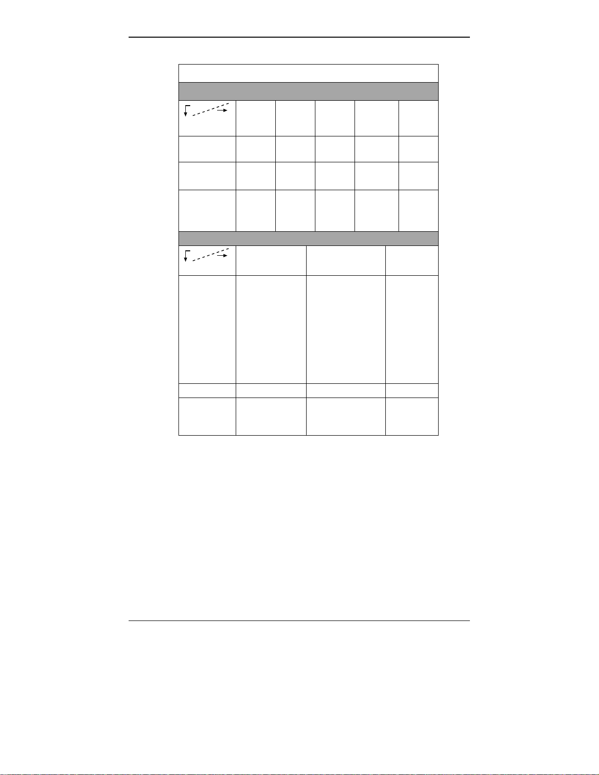
Digital MultiVOIP Products
MVP-
2410
Description
Model
Function T1
digital
VOIP
unit
Capacity 24
channels
Chassis/
Mounting
19” 1U
rack
mount
MVP
24-48
T1
digital
VOIP
add-on
card
24
added
channels
circuit
card
only
E1
digital
VOIP
unit
channels
19” 1U
rack
mount
MVP
3010
30
MVP
30-60
E1
digital
VOIP
add-on
card
30
added
channels
circuit
card
only
9
Page 10
Overview MultiVOIP User Guide
Analog MultiVOIP Products
Description
Model
Function analog
Capacity 8
Chassis/
Mounting
Description
Model
MVP
810
voip
channels
19” 1U
rack
mount
MVP
810 SS
MVP
428
add-on
card
4 added
channels
circuit
card
only
MVP
410
analog
voip
channels
19” 1U
rack
mount
MVP
410SS
MVP
210
analog
voip
4
channels
Table
top
MVP130/
130FXS
analog
voip
2
1
channel
table
top
MVP
210SS
Function analog voip; acts
as minimal SIP
proxy server
giving SIP
proxy
redundancy to
WAN
analog voip; acts
as minimal SIP
proxy server
giving SIP proxy
redundancy to
WAN
analog
voip; acts
as minimal
SIP proxy
server
giving SIP
proxy
redundancy
to WAN
Capacity 8 channels 4 channels 2 channels
Chassis/
Mounting
19” 1U
rack
mount
19” 1U
rack
mount
table-top
unit
10
Page 11

MultiVOIP User Guide Overview
ISDN/BRI MultiVOIP Products
Description
Model
Function ISDN-BRI voip ISDN-BRI voip
Capacity 4 ISDN lines
Chassis/
Mounting
1. “BRI” means Basic Rate Interface.
MVP810ST MVP410ST
2 ISDN lines
(8 B-channels)
19” 1U rack mount 19” 1U rack mount
(4 B-channels)
11
Page 12
Overview MultiVOIP User Guide
Introduction to Analog MultiVOIPs
with SIP Survivability Features
(MVP-210SS/410SS/810SS)
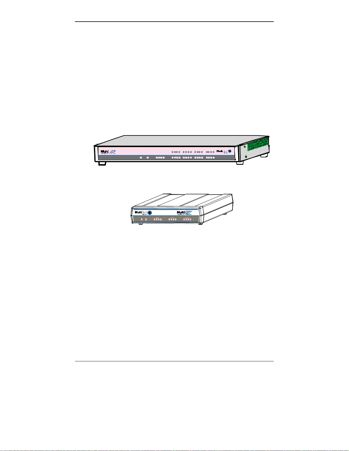
VOIP: The Free Ride. We proudly present Multi-Tech's MVP210SS/410SS/810SS MultiVOIP Voice-over-IP Gateways. These three
models allow voice/fax communication to be transmitted at no
additional expense over your existing IP network, which has ordinarily
been data only. To access this free voice and fax communication, you
simply connect the MultiVOIP to your telephone equipment and your
existing Internet connection. These analog MultiVOIPs inter-operate
readily with T1 or E1 MultiVOIP units.
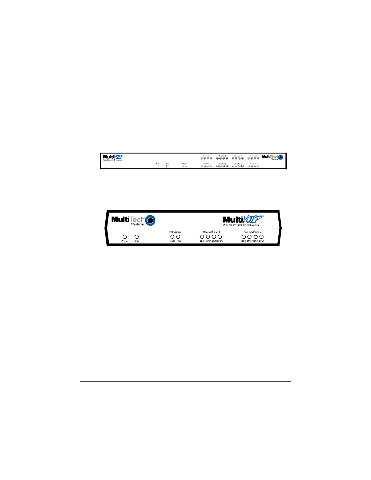
Voice/Fax 5 Voice/Fax 6Voice/Fa x 7Voice/Fax 8
Power
XMT RCVXSG RSG XMTRCV XSG RSGXMT RCV XSGRSG
RCV XMT COLLNK XMTRCV XS G RSG
Voice/Fax 1 Voice/Fax 2Voice/Fax 3 Voi ce/Fax 4EthernetBoot
XMT RCVXSG RSG
Figure 1-1: MVP-410SS/810SS Chassis
XMT RCV XSGRSG
XMTRCV XSG RSG
XMTRCV XSG RSG
Figure 1-2: MVP210SS Chassis
12
Page 13
MultiVOIP User Guide Overview
Capacity. MultiVOIP model MVP810SS is an eight-channel unit, the
model MVP410SS is a four-channel unit, and the MVP210SS is a twochannel unit. All three of these MultiVOIP units have a 10/100Mbps
Ethernet interface and a command port for configuration.
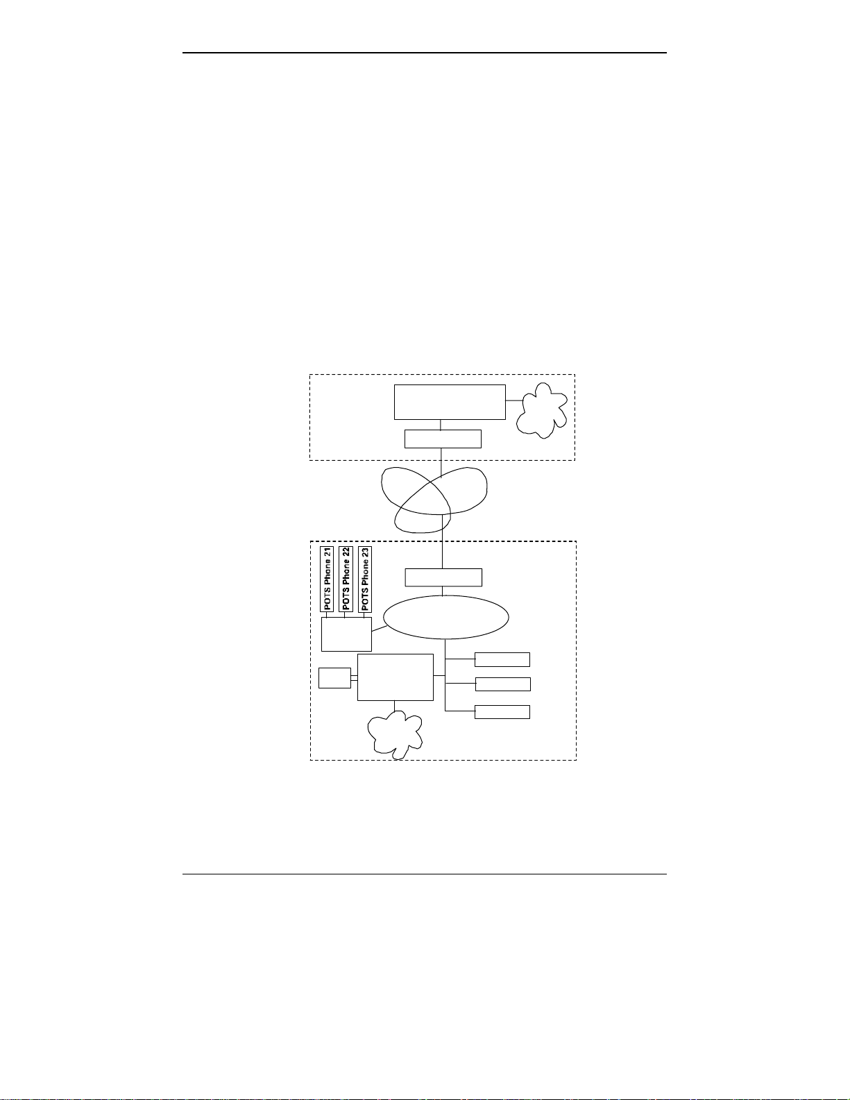
SIP Survivability. The MVP210SS, MVP410SS and MVP810SS have a
special capacity that reaches beyond ordinary voip functionality: they
can direct call traffic for phones connected to their channels or phones
connected to channels of other SIP gateways in the network (this is
basic SIP server functionality). The MVP-SS unit would normally be
located at a remote branch office served by a central SIP server (PBX) at
the organization’s main office. The MVP-SS is intended as a backup in
case the network’s main SIP server (often a PBX) fails or loses contact
with the group of gateways at the remote branch office. If the main SIP
server fails, the MVP-SS allows branch office phone users to call each
other and access the PSTN via POTS lines or a key telephone system.
Main Office
Central SIP Server
(Main PBX)
Router
PSTN
Internet
Branch Office
Router
Ordi nary
SIP
Gateway
POTS
or KTS
SIP Survivability
Server &
Gate way
PST N
Figure 1-3: SIP Survivability MultiVOIP in system
LAN
SIP Phone 1
SIP Pho ne 2
SIP Phone 3
A single MVP210SS, MVP410SS or MVP810SS can provide SIP server
functionality for as many as 500 other voip gateways. However, the
number of phone lines that these units support (4 for the MVP410SS; 8
13
Page 14

Overview MultiVOIP User Guide
for the MVP810SS) constitutes a practical limitation on their capacity to
support PSTN access for other gateways. Systems must be scaled to
match required capacity by including additional MultiVOIP-SS units.
Mounting. Mechanically, the MVP410SS and MVP810SS MultiVOIPs
are designed for a one-high industry-standard EIA 19-inch rack
enclosure. The product must be installed by qualified service personnel
in a restricted-access area, in accordance with Articles 110-16, 10-17, and
110-18 of the National Electrical Code, ANSI/NFPA 70.
Phone System Transparency. These MultiVOIPs inter-operate with a
telephone switch or PBX, acting as a switching device that directs voice
and fax calls over an IP network. The MultiVOIPs have “phonebooks,”
directories that determine to who calls may be made and the sequences
that must be used to complete calls through the MultiVOIP. The
phonebooks allow the phone user to interact with the VOIP system just
as they would with an ordinary PBX or telco switch. When the
phonebooks are set, special dialing sequences are minimized or
eliminated altogether. Once the call destination is determined, the
phonebook settings determine whether the destination VOIP unit must
strip off or add dialing digits to make the call appear at its destination
to be a local call.
Voip Protocol. The MVP-SS units use the SIP protocol only. (“SIP”
means Session Initiation Protocol.)
Data Compression & Quality of Service. The analog MultiVOIP unit
comes equipped with a variety of data compression capabilities,
including G.723, G.729, and G.711 and features DiffServ quality-ofservice (QoS) capabilities.
PSTN Failover Feature. The MultiVOIP can be programmed to divert
calls to the PSTN temporarily in case the IP network fails.
RADIUS Support. Inter-operation with a RADIUS server allows for
call accounting (especially for billing) on a voip system. The MultiVOIP
supports inter-operation with RADIUS servers for the RADIUS
accounting function (but not the RADIUS authentication function).
STUN Support. The STUN protocol (Simple Traversal of UDP through
NATs (Network Address Translation)) assists with the packet routing
functions of devices behind NAT firewalls or routers. The MultiVOIP
supports inter-operation with STUN servers and NATs (SIP based
environment only).
Management. Configuration and system management can be done
locally with the MultiVOIP configuration software. After an IP address
has been assigned locally, other configuration can be done remotely
using the MultiVOIP web browser GUI. Remote system management
can be done with the MultiVoipManager SNMP software or via the
14
Page 15
MultiVOIP User Guide Overview
MultiVOIP web browser GUI. All of these control software packages
are included on the Product CD.
While the web GUI’s appearance differs slightly, its content and
organization are essentially the same as that of the Windows GUI
(except for logging).
15
Page 16
Overview MultiVOIP User Guide
The primary advantage of the web GUI is remote access for control and
configuration. The controller PC and the MultiVOIP unit itself must
both be connected to the same IP network and their IP addresses must
be known.
Once you’ve begun using the web browser GUI, you can go back to the
MultiVOIP Windows GUI at any time. However, you must log out of
the web browser GUI before using the MultiVOIP Windows GUI.
Logging of System Events. MultiTech has built SysLog Server
functionality into the software of the MultiVOIP units. SysLog is a de
facto standard for logging events in network communication systems.
The SysLog Server resides in the MultiVOIP unit itself. To implement
this functionality, you will need a SysLog client program (sometimes
referred to as a “daemon”). SysLog client programs, both paid and
freeware, can be obtained from Kiwi Enterprises, among other firms.
See www.kiwisyslog.com
. SysLog client programs essentially give you
a means of structuring console messages for convenience and ease of
use.
MultiTech Systems does not endorse any particular SysLog client
program. SysLog client programs by any qualified provider should
suffice for use with MultiVOIP units. Kiwi’s brief description of their
SysLog program indicates the typical scope of such programs. “Kiwi
Syslog Daemon is a freeware Syslog Daemon for the Windows
platform. It receives, logs, displays and forwards Syslog messages from
hosts such as routers, switches, Unix hosts and any other syslog
enabled device. There are many customizable options available.”
16
Page 17
MultiVOIP User Guide Overview
MultiVOIP Front Panel LEDs
LED Types. The MultiVOIPs have two types of LEDs on their front
panels:
(1) general operation LED indicators (for power, booting, and
ethernet functions), and
(2) channel operation LED indicators that describe the data traffic
and performance in each VOIP data channel.
Active LEDs. On both the MVP410SS and MVP810SS, there are eight
sets of channel-operation LEDs. However, on the MVP410SS, only the
lower four sets of channel-operation LEDs are functional. On the
MVP810SS, all eight sets are functional.
Figure 1-4. MVP-410SS/810SS LEDs
Similarly, the MVP210 has the general-operation indicator LEDs and
two sets of channel-operation LEDs, one for each channel.
Figure 1-5. MVP210SS LEDs
17
Page 18

Overview MultiVOIP User Guide
LED Descriptions for MultiVOIP-SS Units
Front Panel LED Definitions
LED NAME DESCRIPTION
General Operation LEDs (one set on each MultiVOIP model)
Power Indicates presence of power.
Boot
Ethernet
After power up, the Boot LED will be on briefly while the
MultiVOIP is booting. It lights whenever the MultiVOIP is
booting or downloading a setup configuration data set.
FDX. LED indicates whether Ethernet connection is
half-duplex or full-duplex (FDX) and, in half-duplex
mode, indicates occurrence of data collisions. LED is
on constantly for full-duplex mode; LED is off
constantly for half-duplex mode. When operating in
half-duplex mode, the LED will flash during data
collisions.
LNK. Link/Activity LED. This LED is lit if Ethernet
connection has been made. It is off when the link is
down (i.e., when no Ethernet connection exists).
While link is up, this LED will flash off to indicate data
activity.
Channel-Operation LEDs (one set for each channel)
XMT
RCV
XSG
RSG
Transmit. This indicator blinks when voice packets
are being transmitted to the local area network.
Receive. This indicator blinks when voice packets
are being received from the local area network.
Transmit Signal. This indicator lights when the FXSconfigured channel is off-hook, the FXO-configured
channel is receiving a ring from the Telco, or the M
lead is active on the E&M configured channel. That is,
it lights when the MultiVOIP is receiving a ring from
the PBX.
Receive Signal. This indicator lights when the FXSconfigured channel is ringing, the FXO-configured
channel has taken the line off-hook, or the E lead is
active on the E&M-configured channel.
18
Page 19

MultiVOIP User Guide Overview
Computer Requirements
The computer on which the MultiVOIP’s configuration program is
installed must meet these requirements:
• must be IBM-compatible PC with MS Windows operating
system;
• must have an available COM port for connection to the
MultiVOIP.
However, this PC does not need to be connected to the MultiVOIP
permanently. It only needs to be connected when local configuration
and monitoring are done. Nearly all configuration and monitoring
functions can be done remotely via the IP network.
19
Page 20

Overview MultiVOIP User Guide
Specifications
Parameter
/Model
Operating
Voltage/
Current
Mains
Frequencies
Power
Consumption
Mechanical
Dimensions
Weight 7.1 lbs.
MVP410SS
100-240 VAC
1.2 - 0.6 A
50/60 Hz 50/60 Hz 50/60 Hz
29 watts 46 watts 19 watts
1.75” H x
17.4” W x
8.5” D
4.5cm H x
44.2 cm W x
21.6 cm D
(3.2 kg)
MVP810SS MVP210SS
100-240 VAC
1.2 - 0.6 A
1.75” H x
17.4” W x
8.5” D
4.5cm H x
44.2 cm W x
21.6 cm D
7.7 lbs.
(3.5 kg)
External
transformer:
3A @5V
6.2” W x
9” D x
1.4” H
15.8cm W x
22.9cm D x
3.6cm H
1.8lbs (.82kg)
2.6lbs (1.17kg)
with transformer
20
Page 21

MultiVOIP User Guide Overview
Installation at a Glance
The basic steps of installing your MultiVOIP network involve
unpacking the units, connecting the cables, and configuring the units
using management software (MultiVOIP Configuration software) and
confirming connectivity with another voip site. This process results in a
fully functional Voice-Over-IP network.
Related Documentation
The MultiVOIP User Guide (the document you are now reading) comes
in electronic form and is included on your system CD. It presents indepth information on the features and functionality of Multi-Tech’s
MultiVOIP Product Family. The MultiVOIP is shipped with a printed
Cabling Guide.
The CD media is produced using Adobe Acrobat
printing the user guide. To view or print your copy of a user guide,
load Acrobat Reader
on the MultiVOIP CD and is also a free download from Adobe’s Web
Site:
TM
on your system. The Acrobat Reader is included
TM
for viewing and
www.adobe.com/prodindex/acrobat/readstep.html
This MultiVOIP User Guide is also available on Multi-Tech’s Web site at:
http://www.multitech.com
Viewing and printing a user guide from the Web also requires that you
have the Acrobat Reader loaded on your system. To select the MultiVOIP
User Guide from the Multi-Tech Systems home page, click Documents and then click
MultiVOIP Fam il y in the product list drop-down window. All documents for this
MultiVOIP Product Family will be displayed. You can then choose User Guide
(MultiVOIP Product Family) to view or download the .pdf file. (Note that the
configuration of the MultiTech home page is subject to change. The current User Guide
will be present, in any case.
Entries (organized by model number) in the “knowledge base” and
‘troubleshooting resolutions’ sections of the MultiTech web site (found
under “Support”) constitute another source of help for problems
encountered in the field.
21
Page 22

Quick Start MultiVOIP User Guide
Chapter 2: Quick Start Instructions
22
Page 23

MultiVOIP User Guide QS: Intro
Introduction
This chapter contains streamlined instructions to get the MultiVOIP up
and running quickly. These start-up instructions include assistance on
setting up the MultiVOIP’s Inbound and Outbound Phonebooks. These
sections of the Quick Start Instructions may be particularly useful for
phonebook configuration:
Phonebook Starter Configuration
Phonebook Tips
Phonebook Example (One Common Situation)
The Quick Start Guide also contains a “Phonebook Worksheet” section.
You may want to print out several worksheet copies. Paper copies can
be very helpful in comparing phonebooks at multiple sites at a glance.
This will assist you in making the phonebooks clear and consistent and
will reduce ‘surfing’ between screens on the configuration program.
A printed Cabling Guide is shipped with the MultiVOIP and an
electronic copy is included on the Product CD.
23
Page 24

MultiVOIP User Guide QS: Startup Tasks
MultiVOIP Startup Tasks
Task Summary
Collecting Phone/IP
Details ( vital! )
Placement
Command/Control
Computer Setup:
Specs & Settings
The MultiVOIP must be configured to
interface with your particular phone
system and IP network. To do so,
certain details must be known about
those phone and IP systems.
Decide where you’ll mount the voip.
Some modest minimum specifications
must be met. A COM port must be set
up.
Hookup Connect power, phone, and data cables
per diagram.
Software Installation This is the configuration program.
It’s a standard Windows software
installation.
Phone/IP Starter
Configuration
Phonebook Starter
Configuration
You will enter phone numbers and IP
addresses. You’ll use default parameter
values where possible to get the system
running quickly.
Use “Config Info CheckList” (page 28).
The phonebook is where you specify
how calls will be routed. To get the
system running quickly, you’ll make
phonebooks for just two voip sites.
Connectivity Test You’ll find out if your voip system can
carry phone calls between two sites.
That means you’re up and running!
Troubleshooting Detect and remedy any problems that
might have prevented connectivity.
24
Page 25

MultiVOIP User Guide QS: Gathering Phone/IP Details
Phone/IP Details *Absolutely Needed*
Before Starting the Installation
The MultiVOIP will interface with both the IP network and the phone
system. You must gather information about the IP network and about
the phone system so that the MultiVOIP can be configured to operate
with them properly. A summary of this configuration information
appears on page 28 (“Config Info CheckList”).
Gather IP Information
Ask your computer network
administrator.
#
• IP Address
• IP Mask
• Gateway
• Domain Name Server (DNS) Info (optional)
• Determine whether or not 802.1p Packet Prioritization
will be used.
IP Network Parameters:
Record for each VOIP Site
in System
Info needed to operate:
all MultiVOIP models.
25
Page 26

QS: Gathering Phone/IP Details MultiVOIP User Guide
Phone/IP Details *Absolutely Needed*
Gather Telephone Information
Telephony Parameters
Ask phone company or
telecom manager.
#
• Which interface type is used?
E&M_____ FXS/FXO_____ DID/DPO _____
• If FXS, determine whether the line will be used for a
phone, fax, or KTS (key telephone system)
• If FXO, determine if line will be an analog PBX
extension or an analog line from a telco central office
• If E&M, determine these aspects of the E&M trunk
line from the PBX:
• What is its Type (1, 2, 3, 4, or 5)?
• Is it 2-wire or 4-wire?
• Is it Dial-Tone or Wink?
Analog Telephony Interface Parameters:
Record for this VOIP Site
26
Page 27
MultiVOIP User Guide QS: Gathering Phone/IP Details
Phone/IP Details Often Needed/Wanted
Obtain Email Address for VOIP (for email call log reporting)
required if log reports of
VOIP call traffic
are to be sent by email
SMTP Parameters
Preparation Task:
Ask Mail Server
administrator to set up
email account (with
password) for the
MultiVOIP unit itself.
Be sure to give a unique
identifier to each
individual MultiVOIP
unit.
Get the IP address of the
mail server computer, as
well.
Optional
To: I .T. De par tme nt
re: email accoun t for VOIP
voip-unit2@biggytech.com
27
Page 28

QS: Gathering Phone/IP Details MultiVOIP User Guide
Config Info CheckList
Type of Config Info
Gathered
MultiVOIP
Configuration
screen
on which to enter
Config Info
IP info for voip unit
● IP address
● Gateway
● DNS IP (if used)
● 802.1p Prioritization
(if used)
Interface Type
(Choices: E&M, FXS/FXO*,
DIP, DPO)
E&M info (only if E&M is used)
● Type (1-5) ● 2 or 4 wires?
● Dial Tone or Wink?
Country Code Regional Parameters
Email address for voip (optional) SMTP Parameters
SIP Operating Mode
● Survivability ● Stand-Alone
Network Locations of Alternate
SIP Proxy units, if used
(IP Address or Domain Name)
Alt #1:
Alt #2
Endpoint Info
Device Name Regist Type
IP Address Port
-------------------------------------Device Name Regist Type
IP Address Port
Reminder: Be sure to Save Setup after entering configuration values.
Ethernet/IP Parameters
Interface Parameters
*In FXO/FXS systems,
channels used for phone, fax,
or key system are FXS;
channels used for analog
PBX extensions or analog
telco lines are FXO.
Interface Parameters
SIP Server Configuration
SIP Call Signaling
SIP Server Predefined
Endpoints
√
28
Page 29

MultiVOIP User Guide QS: Gathering Phone/IP Details
Identify Remote VOIP Site to Call
When you’re done installing the MultiVOIP, you’ll want to confirm that
it is configured and operating properly. To do so, it’s good to have
another voip that you can call for testing purposes. You’ll want to
confirm end-to-end connectivity. You’ll need IP and telephone
information about that remote site.
If this is the very first voip in the system, you’ll want to coordinate the
installation of this MultiVOIP with an installation of another unit at a
remote site.
Identify MVP-SS Unit’s Role in SIP VOIP System
The MVP210-SS/410-SS/810-SS unit always uses the SIP protocol.
However, the MVP-SS units are equipped to play an additional role in
the voip system -- the role of a SIP server. And as a SIP server, the
MVP-SS unit can operate in either “stand-alone” mode or “SIP
survivability” mode.
Stand-Alone Mode. The MVP-SS unit can function as a stand-alone SIP
server that controls the flow of phone traffic to lines connected to
gateways that are registered with the MVP-SS unit. This stand-alone
capability allows the MVP-SS to operate with ‘smart’ SIP phones. Such
smart SIP phones can choose the SIP server under which they operate
and, consequently, can be controlled by either the SIP-based PBX or by
the MVP-SS.
SIP Survivability Mode. The MVP-SS unit can function as a back-up SIP
server that performs SIP server functions when/if the network’s main
SIP server fails or loses contact with the subnetwork in which the
MVP-SS unit is placed.
29
Page 30

QS: Voip Placement & PC Settings MultiVOIP User Guide
Placement
Mount your MultiVOIP in a safe and convenient location where cables
for your network and phone system are accessible. Rack-mounting
instructions are in Chapter 3: Mechanical Installation & Cabling of the User
Guide.
Command/Control Computer Setup (Specs & Settings)
The computer used for command and control of the MultiVOIP
(a) must be an IBM-compatible PC,
(b) must use a Microsoft operating system,
(c) must be connected to your local network (Ethernet) system, and
(d) must have an available serial COM port.
The configuration tasks and control tasks the PC will have to do with
the MultiVOIP are not especially demanding. Still, we recommend
using a reasonably new computer. The computer that you use to
configure your MultiVOIP need not be dedicated to the MultiVOIP
after installation is complete.
COM port on controller PC. You’ll need an available COM port on the
controller PC. You’ll need to know which COM port is available for use
with the MultiVOIP (COM1, COM2, etc.).
30
Page 31

MultiVOIP User Guide QS: Quick Hookups
Quick Hookup for MVP410-SS & MVP810-SS
31
Page 32

QS: Quick Hookups MultiVOIP User Guide
Quick Hookup for MVP210-SS
CH1 CH2
ETHERNET
E&M
FXS/FXO
10/100
10BASET
RS232
COMMAND
COMMAND PORT
POWER
POWER
E&M
FXS/FXO
Voice/Fax Channel 1 - 2
Connections
PSTN
E&M FXO/FXS
E&M
FXO
GND
FXS
Power Connection
Command Port Connection
Ethernet Connection
32
Page 33

QS: Software Installation MultiVOIP User Guide
Load MultiVOIP Control Software onto PC
For more details, see Chapter 4: Software Installation in User Guide.
1. MultiVOIP must be properly cabled. Power must be turned on.
2. Insert MultiVOIP CD into drive. Allow 10-20 seconds for Autorun to
start. If Autorun fails, go to
My Computer | CD ROM drive | Open. Click Autorun icon.
3. At first dialog box, click Install Software.
4. At ‘welcome’ screen, click Next.
5. Follow on-screen instructions. Accept default program folder
location and click Next.
6. Accept default icon folder location. Click Next. Files will be copied.
7. Select available COM port on command/control computer.
8. At completion screen, click Finish.
9. At the prompt “Do you want to run MultiVOIP Configuration?,”
click No. Software installation is complete.
33
Page 34

QS: Phone/IP Starter Config. MultiVOIP User Guide
Phone/IP Starter Configuration
This is a summary. For full details, see “Technical Configuration”
chapter of User Guide.
1. Open MultiVOIP program: Start | MultiVOIP xxx | Configuration.
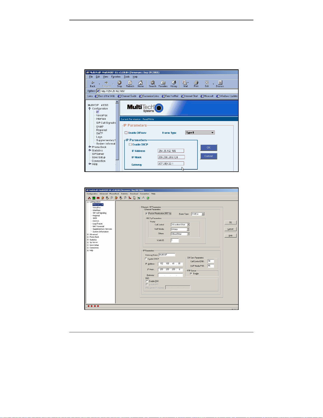
2. Go to Configuration | Ethernet/IP. Enter the IP parameters for your
voip site. Activate Packet Prioritization (802.1p) if desired. If you use a
Domain Name Server (DNS), specify its IP address. If DNS is used, you
can activate the Service Record (SRV) feature. For details, see the
“Technical Configuration” chapter of the User Guide.
3. Do you want to configure and operate the MultiVOIP unit using the
web browser GUI? (It has the same functionality as the local
Windows GUI, but offers remote access.)
If NO, skip to step 5.
If YES, continue with step 4.
34
Page 35

MultiVOIP User Guide QS: Phone/IP Starter Config.
4. Web Browser GUI Setup (Optional). To do configuration and
operation procedures using the web browser GUI, you must first set
it up. To do so, follow these steps. (The browser used must be
Internet Explorer 6.0 or above; or Netscape 6.0 or above; or FireFox
1.0 or above.)
A. Be sure an IP address has
been assigned to the
MultiVOIP unit (this must be
done in the MultiVOIP
Windows GUI).
E. Open web browser.
(Note: The PC being used must
be connected to and have an IP
address on the same IP network
that the voip is on.)
B. Save Setup in Windows GUI. F. Browse to IP address of
MultiVOIP unit.
C. Close the MultiVOIP
Windows GUI.
G. If username and password
have been established, enter
them when prompted by
voip.
D. Install Java program from
MultiVOIP product CD.
(Must be Java Runtime
Environment 1.4.2_01 or above.)
NOTE: Required on first use of
Web Browser GUI only.
Need more
info?
See “Web Browser Interface” in Operation &
Maintenance chapter of User Guide (on CD).
H. Use web browser GUI to
configure or operate voip.
Once you’ve begun using the web browser GUI, you can go back
to the MultiVOIP Windows GUI at any time. However, you must
log out of the web browser GUI before using the MultiVOIP
Windows GUI.
35
Page 36

QS: Phone/IP Starter Config. MultiVOIP User Guide
Phone/IP Starter Configuration (continued)
5. Go to Configuration | Voice/Fax. Select Coder | “Automatic.” At
the right-hand side of the dialog box, click OK. If you know any
specific parameter values that will apply to your system, enter them.
Click Copy Channel. Select Copy to All. Click Copy. At main
Voice/Fax Parameters screen, click OK to exit from the dialog box.
6. Enter telephone system information.
Go to Configuration | Interface.
Enter parameters obtained from
phone company or PBX administrator.
7. Go to Configuration | Regional Parameters. Select the
Country/Region that fits your situation. Click OK and confirm.
Click OK to exit from the dialog box.
8. Go to Configuration | Regional Parameters. In the Country
Selection for Built-In Modem field (drop-down list), select the
country that best fits your situation. (This may not be the same as
your selection for the Country/Region field. The selections in the
Country Selection for Built-In Modem field entail more detailed
groupings of telephony parameters than do the Country/Region
values.)
9. Do you want the phone-call logs produced by the MultiVOIP to be
sent out by email (to your Voip Administrator or someone else)?
If NO, skip to step 11.
If YES, continue with step 10.
10. Go to Configuration | SMTP.
SMTP lets you send phone-call log records to the Voip Administrator
by email. Select Enable SMTP.
You should have already obtained an email address for the
MultiVOIP itself (this serves as the origination email account for
email logs that the MultiVOIP can email out automatically).
Enter this email address in the “Login Name” field.
Type the password for this email account.
Enter the IP address of the email server where the MultiVOIP’s email
account is located in the “Mail Server IP Address” field.
Typically the email log reports are sent to the Voip Administrator
but they can be sent to any email address. Decide where you want
the email logs sent and enter that email address in the “Recipient
Address” field.
36
Page 37

MultiVOIP User Guide QS: Phone/IP Starter Config.
Whenever email log messages are sent out, they must have a
standard Subject line. Something like “Phone Logs for Voip N” is
useful. If you have more than one MultiVoip unit in the building,
you’ll need a unique identifier for each one (select a useful name or
number for “N”). In this “Subject” field, enter a useful subject title for
the log messages.
In the “Reply-To Address” field, enter the email address of your Voip
Administrator.
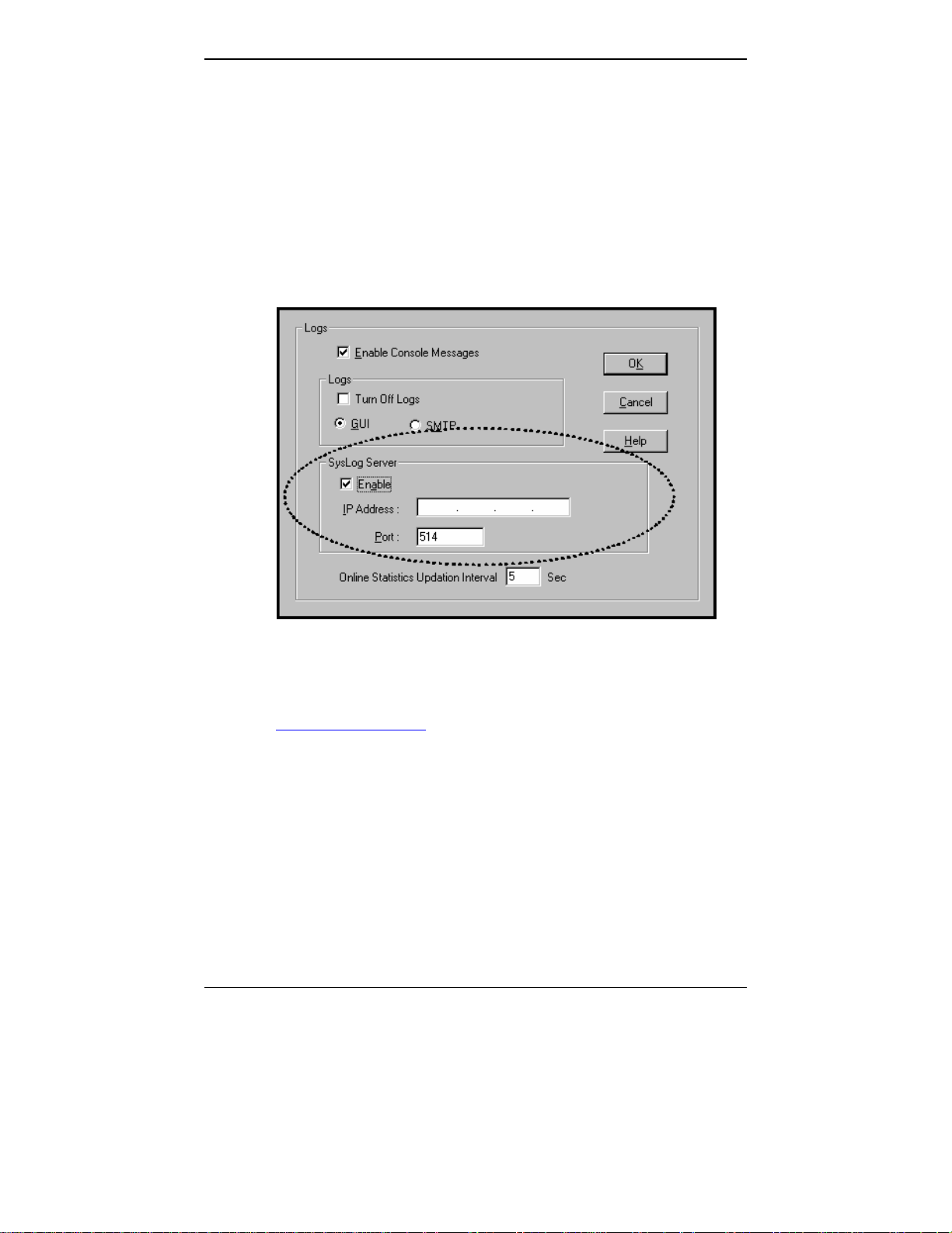
11. Go to Configuration | Logs.
Select “Enable Console Messages.”
To allow log reports by email (if desired), click SMTP. Click OK.
To do logging with a SysLog client program, click on “SysLog Server
– Enable” in the
Logs screen. To implement this function, you must
install a SysLog client program. For more info, see the “SysLog
Server Functions” section of the Operation & Maintenance chapter of
the
User Guide.
37
Page 38

QS: Phone/IP Starter Config. MultiVOIP User Guide
Phone/IP Starter Configuration (continued)
12. Enable premium (H.450) telephony features.
Go to
Supplementary Services. Select any features to be used.
For Call Hold, Call Transfer, & Call Waiting, specify the key sequence
that the phone user will press to invoke the feature. For Call Name
Identification, specify the allowed name types to be used and a callerid descriptor.
If Call Forwarding is to be used, enable this feature in the
Add/Edit Inbound Phone Book screen.
After making changes, click on OK in the current configuration
screen before moving on to the next configuration screen.
13.
RADIUS Support. If you intend to use a RADIUS server for billing or
other accounting purposes, enter the server information in the
RADIUS screen.
14.
STUN Support. If you are using the SIP protocol with the UDP
transmission protocol, and if you want the MultiVOIP to operate
behind a NAT (Network Address Translation server) using the STUN
protocol (Simple Traversal of UDP through NAT), enable this feature
in the NAT Traversal screen. You must also specify the IP address
(etc.) of the STUN server you will use. The STUN server could be a
local device or it could be a public STUN server accessible on the
Internet.
15.
Network Locations of SIP Servers (Primary & Alternate).
Go to SIP Call Signaling and enter the IP address or domain name for the
primary SIP Server in your system, as well as any alternate SIP servers.
The UserName and Password entered here will be used to
authenticate all inbound phonebook entries that do not already have
their own unique usernames and passwords.
16.
Endpoint Info. Go to SIP Server | Predefined Endpoints.
For every other endpoint (gateway) to be registered with the
MultiVOIP-SS unit, enter values for the following parameters.
The parameters required are different for static registrations than for
dynamic registrations, as shown in the table below.
Static Registration Dynamic Registration
Endpoint Name =
IP Address:
. . .
Port #: Re-Registrat. Interval (sec):
Endpoint Name =
Password:
38
Page 39

MultiVOIP User Guide QS: Phone/IP Starter Config.
17. Go to Save Setup | Save and Reboot. Click OK. This will save the
parameter values that you have just entered.
The MultiVOIP’s “BOOT” LED will light up while the configuration
file is being saved and loaded into the MultiVOIP. Don’t do anything
to the MultiVOIP until the “BOOT “LED is off (a loss of power at this
point could cause the MultiVOIP unit to lose the configuration
settings you have made).
END OF PROCEDURE.
39
Page 40

QS: Phonebook Starter Config. MultiVOIP User Guide
Phonebook Starter Configuration (with remote voip)
If the topic of voip phone books is new to you, it may be helpful to read
the PhoneBook Tips section (page 47) before starting this procedure.
To do this part of the quick setup, you need to know of another voip
that you can call to conduct a test. It should be at a remote location,
typically somewhere outside of your building. You must know the
phone number and IP address for that site. We are assuming here that
the MultiVOIP will operate in conjunction with a PBX.
You must configure both the Outbound Phonebook and the Inbound
Phonebook. A starter configuration only means that two voip locations
will be set up to begin the system and establish voip communication.
Outbound Phonebook
1. Open the MultiVOIP program.
( Start | MultiVOIP xxx | Configuration )
2. Go to Phone Book | Outbound Phonebook | Add Entry.
3. On a sheet of paper, write down the calling code of the remote voip
(area code, country code, city code, etc.) that you’ll be calling.
Follow the example that best fits your situation.
North America,
Long-Distance Example
Technician in Seattle (area
206) must set up one voip
there, another in Chicago
(area 312, downtown).
Answer: Write down 312.
Euro, National Call
Example
Technician in central
London (area 0207) to set
up voip there, another in
Birmingham (area 0121).
Answer: write down 0121.
Euro, International Call Example
Technician in Rotterdam (country 31; city 010) to
set up one voip there, another in Bordeaux
(country 33; area 05).
Answer: write down 3305.
40
Page 41

MultiVOIP User Guide QS: Phonebook Starter Config.
4. Suppose you want to call a phone number outside of your building
using a phone station that is an extension from your PBX system (if
present). What digits must you dial? Often a “9” or “8” must be
dialed to “get an outside line” through the PBX (i.e., to connect to the
PSTN). Generally, “1 “or “11” or “0” must be dialed as a prefix for
calls outside of the calling code area (long-distance calls, national
calls, or international calls).
On a sheet of paper, write down the digits you must dial before you
can dial a remote area code.
North America,
Long-Distance Example
Seattle-Chicago system.
Seattle voip works with
PBX that uses “8” for all
voip calls. “1” must
immediately precede area
code of dialed number.
Answer: write down 81.
Euro, National Call
Example
London/Birming. system.
London voip works with
PBX that uses “9” for all
out-of-building calls
whether by voip or by
PSTN. “0” must
immediately precede area
code of dialed number.
Answer: write down 90.
Euro, International Call Example
Rotterdam/Bordeaux system.
Rotterdam voip works with PBX where “9” is
used for all out-of-building calls. “0” must
precede all international calls.
Answer: write down 90.
41
Page 42
QS: Phonebook Starter Config. MultiVOIP User Guide
5. In the “Destination Pattern” field of the Add/Edit Outbound
Phonebook screen, enter the digits from step 4 followed by the digits
from step 3.
North America,
Long-Distance Example
Seattle-Chicago system.
Answer: enter 81312 as
Destination Pattern in Outbound
Phone-book of
Seattle voip.
Euro, National Call
Example
London/Birming. system.
Leading zero of
Birmingham area code is
dropped when combined
with national-dialing
access code. (Such
practices vary by country.)
Answer: enter 90121 as
Destination Pattern in Outbound
Phonebook of
London voip.
Not 900121.
Euro, International Call Example
Rotterdam/Bordeaux system.
Answer: enter 903305 as Destination Pattern in
Outbound Phonebook of Rotterdam voip.
42
Page 43

MultiVOIP User Guide QS: Phonebook Starter Config.
6. In the “Remove Prefix” field, enter the initial PBX access digit (“8” or
“9”).
North America,
Long-Distance Example
Seattle-Chicago system.
Answer: enter 8 in “Remove
Prefix” field of
Seattle Outbound
Phonebook.
Euro, National Call
Example
London/Birming. system.
Answer: enter 9 in “Remove
Prefix” field of
London Outbound
Phonebook.
Euro, International Call Example
Rotterdam/Bordeaux system.
Answer: enter 9 in “Remove Prefix” field of Outbound
Phonebook for Rotterdam voip.
Some PBXs will not ‘hand off’ the “8” or “9” to the voip. But for those PBX
units that do, it’s important to enter the “8” or “9” in the “Remove Prefix”
field in the Outbound Phonebook. This precludes the problem of having to
make two inbound phonebook entries at remote voips, one to account for
situations where “8” is used as the PBX access digit, and another for when
“9” is used.
7. In the “SIP” field group, select “Use Proxy” and specify the Transport
Protocol to be used (TCP or UDP). Use the default SIP Port Number
(5060).
8. Click OK to exit from the Add/Edit Outbound Phonebook screen.
43
Page 44

QS: Phonebook Starter Config. MultiVOIP User Guide
Inbound Phonebook
1. Open the MultiVOIP program.
( Start | MultiVOIP xxx | Configuration )
2. Go to Phone Book | Inbound Phonebook | Add Entry.
3. In the “Remove Prefix” field, enter your local calling code (area code,
country code, city code, etc.) preceded by any other “access digits”
that are required to reach your local site from the remote voip
location (think of it as though the call were being made through the
PSTN – even though it will not be).
North America,
Long-Distance Example
Seattle-Chicago system.
Seattle is area 206. Chicago
employees must dial 81
before dialing any Seattle
number on the voip system.
Answer: 1206 is prefix to be
removed by local
(Seattle) voip.
Euro, National Call
Example
London/Birming. system.
Inner London is 0207 area.
Birmingham employees must
dial 9 before dialing any
London number on the voip
system.
Answer: 0207 is prefix to be
removed by local
(London) voip.
Euro, International Call Example
Rotterdam/Bordeaux system.
Rotterdam is country code 31, city code 010. Bordeaux
employees must dial 903110 before dialing any
Rotterdam number on the voip system.
Answer: 03110 is prefix to be removed by local
(Rotterdam) voip.
44
Page 45

MultiVOIP User Guide QS: Phonebook Starter Config.
4. In the “Add Prefix” field, enter any digits that must be dialed from
your local voip to gain access to the PSTN.
North America,
Long-Distance Example
Seattle-Chicago system.
On Seattle PBX, “9” is used to
get an outside line.
Answer: 9 is prefix to be
added by local
(Seattle) voip.
Euro, National Call
Example
London/Birming. system.
On London PBX, “9” is used
to get an outside line.
Answer: 9 is prefix to be
added by local
(London) voip.
Euro, International Call Example
Rotterdam/Bordeaux system.
On Rotterdam PBX, “9” is used to get an outside line.
Answer: 9 is prefix to be added by local (Rotterdam)
voip.
5. In the “Channel Number” field, enter “Hunting.” A “hunting” value
means the voip unit will assign the call to the first available channel.
If desired, specific channels can be assigned to specific incoming calls
(i.e., to any set of calls received with a particular incoming dialing
pattern).
45
Page 46

QS: Phonebook Starter Config. MultiVOIP User Guide
6. In the “Description” field, it is useful to describe the ultimate
destination of the calls. For example, in a New York City voip
system, “incoming calls to Manhattan office,” might describe a
phonebook entry, as might the descriptor “incoming calls to NYC
local calling area.” The description should make the routing of calls
easy to understand. (40 characters max.)
North America,
Long-Distance Example
Seattle-Chicago system.
Possible Description:.
Free Seattle access, all
employees
Euro, National Call
Example
London/Birming. system.
Possible Description:.
Local-rate London access,
all empl.
Euro, International Call Example
Rotterdam/Bordeaux system.
Possible Description:. Local-rate Rotterdam access, all
empl.
7. In the Add/Edit Inbound Phonebook screen, under “Registration
Options,” enter the special password (if any) that will be used for
this inbound phonebook entry. If you specify a special password that
applies only to this inbound phonebook entry, that password will
override the general password used by endpoints registering with the
SIP server (in the SIP Call Signaling screen).
8. Repeat steps 2-8 for each inbound phonebook entry. When all entries
are complete, go to step 9.
9. Click OK to exit the inbound phonebook screen.
10. Click on Save Setup. Highlight Save and Reboot. Click OK.
Your starter inbound phonebook configuration is complete.
46
Page 47

MultiVOIP User Guide QS: Phonebook Tips
Phonebook Tips
Preparing the phonebook for your voip system is a complex task that, at
first, seems quite daunting. These tips may make the task easier.
1.
Use Dialing Patterns, Not Complete Phone Numbers. You will not
generally enter complete phone numbers in the voip phonebook.
Instead, you’ll enter “destination patterns” that involve area codes and
other digits. If the destination pattern is a whole area code, you’ll be
assigning all calls to that area code to go to a particular voip which has
a unique IP address. If your destination pattern includes an area code
plus a particular local phone exchange number, then the scope of calls
sent through your voip system will be narrowed (only calls within that
local exchange will be handled by the designated voip, not all calls in
that whole area code). In general, when there are fewer digits in your
destination pattern, you are asking the voip to handle calls to more
destinations.
2.
The Four Types of Phonebook Digits Used. Important!
“Destination patterns” to be entered in your phonebook will generally
consist of:
(a) calling area codes,
(b) access codes,
(c) local exchange numbers, and
(d) specialized codes.
Although voip phonebook entries may look confusing at first, it’s
useful to remember that all the digits in any phonebook entry must be
of one of these four types.
(a)
calling area codes. There are different names for these around the
world: “area codes,” “city codes,” “country codes,” etc. These codes,
are used when making non-local calls. They always precede the phone
number that would be dialed when making a local call.
47
Page 48

QS: Phonebook Tips MultiVOIP User Guide
(b) access codes. There are digits (PSTN access codes) that must be
dialed to gain access to an operator, to access the publicly switched
‘long-distance’ calling system(North America), to access the publicly
switched ‘national’ calling system (Europe and elsewhere), or to access
the publicly switched ‘international’ calling system (worldwide).
There are digits (PBX access codes) that must be dialed by phones
connected to PBX systems or key systems. Often a “9” must be dialed
on a PBX phone to gain access to the PSTN (‘to get an outside line’).
Sometimes “8” must be dialed on a PBX phone to divert calls onto a
leased line or to a voip system. However, sometimes PBX systems are
‘smart’ enough to route calls to a voip system without a special access
code (so that “9” might still be used for all calls outside of the building).
There are also digits (special access codes) that must be dialed to gain
access to a particular discount long-distance carrier or to some other
closed or proprietary telephone system.
(c)
local exchange numbers. Within any calling area there will be many
local exchange numbers. A single exchange may be used for an entire
small town. In cities, an exchange may be used for a particular
neighborhood (although exchanges in cities do not always cover easily
discernible areas). Organizations like businesses, governments,
schools, and universities are also commonly assigned exchange
numbers for their exclusive use. In some cases, these organizationalassigned exchanges can become non-localized because the exchange is
assigned to one facility and linked, by the organization’s private
network, to other sometimes distant locations.
(d)
specialized codes. Some proprietary voip units assign, to sites and
phone stations, numbers that are not compatible with PSTN
numbering. This can also occur in PBX or key systems. These
specialized numbers must be handled on a case-by-case basis.
48
Page 49

MultiVOIP User Guide QS: Phonebook Tips
3.
Knowing When to Drop Digits. Example
When calling area codes and
access codes are used in
combination, a leading “1” or “0”
must sometimes be dropped.
Phonebook Entry
Area code for Inner London is
listed as “0207.” However, in
international calls the leading
“0” is dropped.
U.K.
Country
Code
International
Access Code
Leading Zero
Dropped from
Area Code
49
Page 50

QS: Phonebook Tips MultiVOIP User Guide
4.
Using a Comma. Detail
Commas are used in telephone
dialing strings to indicate a pause
to allow a dial tone to appear
(common on PBX and key
systems). Commas may be used
only in the “Add Prefix” field of
the Inbound Phonebook.
5.
Ease of Use. The phonebook setup determines how easy the voip
system is to use. Generally, you’ll want to make it so dialing a voip call
is very similar to dialing any other number (on the PSTN or through the
PBX).
6.
Avoid Unintentional Calls to Official/Emergency Numbers. Dialing a
voip call will typically be somewhat different than ordinary dialing.
Because of this, it’s possible to set up situations, quite unwittingly,
where phone users may be predisposed to call official numbers without
intending to do so. Conversely, a voip/PBX system might also make it
difficult to place an official/emergency call when one intends to do so.
Study your phonebook setup and do some test-dialing on the system to
avoid these pitfalls.
, = 1-second pause
in many PBX systems
(not needed in all)
7.
Inbound/Outbound Pattern Matching. In general, the Inbound
Phonebook entries of the local voip unit will match the Outbound
Phonebook entries of the remote voip unit. Similarly, the Outbound
Phonebook entries of the local voip unit will match the Inbound
Phonebook entries of the remote voip unit. There will often be nonmatching entries, but it’s nonetheless useful to notice the matching
between the phonebooks.
8.
Simulating Network in-lab/on-benchtop. One common method of
configuring a voip network is to set up a local IP network in a lab,
connect voip units to it, and perhaps have phones connected on channel
banks to make test calls.
50
Page 51

QS: Phonebook Example MultiVOIP User Guide
Phonebook Example
Boise Office
PBX System.
Main Number:
333-2700
Inbound Phonebook
Each Inbound P honebook contai ns
two entries. The first entry (4 digits)
specifies how incoming calls from the
other voip sites will be handled if
they g o out ont o the local PSTN.
Essentially, all those calls come to the
receiving voip with a pattern
beginni ng wi th
voip removes those four digits
becau se t hey a ren ’t need ed w hen
dialing locally. The local voip
att aches a “ 9” at th e begi nni ng of t he
number to get an outside line. The
PBX then completes the call to the
PSTN .
The second
(1 digit) is for receiving calls from
com pan y em pl oy ees in th e ot her tw o
cities. The out-of-town employee
simp ly d ial s 3 d igi ts. The fi rst of t he
thr ee di gits i s un iquel y used at each
sit e and so act s as a desti nati on
pattern (Boise extensi ons are 7xx,
Sant a Fe ext ensi on s 2xx, Flag staf f
ext ensi ons 6x x).
Th e lo cal v oi p sees t he p att ern in it s
inbou nd phone book and notes the
first digit (here either 2, 5, or 6).
To make the match, this fi rst digit,
2, 5, or 6 is p ut i n t he “ Remov e Prefi x”
field. This first digit must then be
add ed back once ag ain so t hat the
voip will send all three digits to the
PBX. The PBX can then d ial t he
specific extension identified by the
t hree- di gi t n um ber.
Area: 208
90 extensions
204.16.49.73
24-Channel
Digital VoIP
(MVP2410)
1+area code . The local
Inbound Pho nebo ok en tr y
Flagstaff Office
Area: 520
204.16.49.75
8-Channel
Analog VoIP
(MVP810)
PSTN
One Common Situation
Voip Example. This company has offices in three
d i ff er ent ci ti es. T he PB X u ni ts all op erate a li k e.
N ot abl y, t hey all gi ve access to ou tsi de l in es usi ng
“ 9.” Th ey al l are ‘ smar t’ eno ug h t o i den ti fy voi p cal ls
w it hou t u sing a speci al access d igit ( “ 8” is used in
som e syst ems) . Fi nal l y, t he sy stem op er ates so t hat
empl oy ees i n an y o ff ice can d ial empl oy ees in an y
other office using only three digits. Here are the
p ho nebook s need ed fo r th at syst em.
Santa Fe Office
Area: 505
204.16.49.74
8-Channel
Analog VoIP
(MVP810)
IP
Network
Each
pairs of entries, two entries for each
r emo te sit e. Wh enev er an o ut- of -tow n
empl oyee di als a 12- dig i t n um ber
beginning wit h the listed 5-digit
d esti nat io n p att ern (9+1+ area cod e) of
ano th er comp any locati on, th e PBX
ha nd s th e cal l to t he v oi p sy stem. Th e
local voip strips off the “9” and directs
the call to the IP address of the remote
voip . The rem ote voip receiv es the call
an d h and s it t o i ts PB X. T he PBX then
completes the call to the PSTN.
Th e one- d igi t
patterns pertain to 3-digit calling
bet w een co mp any emp l oy ees.
PBX System.
Main Number:
444-3200
PSTN
Outbound Phonebook
Outbound
40 extensions
contains two
destination
PBX System.
Main Number:
777-5600
30 extensions
PSTN
51
Page 52

QS: Phonebook Example MultiVOIP User Guide
Voip Sites with Phonebooks
Boise Office
PBX System.
Main Number:
333-2700
Area: 208
PSTN
90 extensions
Inbound Phonebook Outbound Phonebook
Prefix to
Remove
91208 9, Incoming calls
7 7 i ncoming calls
204.16.49.73
24-Channel
Digital VoIP
(MVP2410)
IP
Network
Santa Fe Voip Santa Fe Voip
Inbound Phonebook Outbound Phonebook
Prefix
to Add
Description
Incoming Calls
to PSTN,
Santa Fe local
calls
to extensions
of company’s
PBX system
in Santa Fe
Prefix to
Remove
91505 9, Incoming calls
2 2 Incoming calls
Tota l
Digits
Prefix to
Remove
Destin.
Pattern
91208 12 none none 204.
7 3 none none 204.
91520 12 none none 204.
6 3 none none 204.
Boise Voip Boise Voip
Prefix
to Add
Description
Incoming Calls
to PSTN,
Boise Area
to extensions
of company’s
PBX system
in Boise
Tota l
Prefix to
Destin.
Digits
Pattern
91505 12 none none
2 3 none none
91520 12 none none 204.
6 3 none none 204.
Remove
Prefix
to AddIPAddr
Santa Fe Office
Prefix
to AddIPAddr
16.49.
73
16.49.
73
16.49.
75
16.49.
75
Description
Outgoing Calls
Outgoing calls
to Boise area
3-digit calls to
Boise
employees
(extensions
700-790)
Outgoing calls
to Flagstaff
area
3-digit calls to
Flagstaff
employees
(extensions
600-630)
PBX System.
Main Number:
444-3200
204.
16.49.
74
204.
16.49.
74
16.49.
75
16.49.
75
Area: 505
204.16.49.74
Analog VoIP
PSTN
Description
Outgoing Calls
Outgoing calls
to Santa Fe
area
3-digit calls to
Santa Fe
employees
(extensions
200 to 240)
Outgoing calls
to Flagstaff
area
3-digit calls to
Flagstaff
employees
(extensions
600-630)
8-Channel
(MVP810)
40 extensio ns
Flagstaff Office
Area: 520
204.16.49.75
8-Channel
Analog VoIP
(MVP810)
PBX System.
Main Number:
777-5600
30 extensions
PSTN
Flagstaff Voip Flagstaff Voip
Inbound Phonebook Outbound Phonebook
Prefix
to Add
Description
Incoming Calls
to PSTN,
Flagstaff local
calls
to extensions
of company’s
PBX system
in Flagstaff
Prefix to
Remove
91520 9 Incoming calls
6 6 Incoming calls
Tota l
Digits
Prefix to
Remove
Destin.
Pattern
91505 12 none none
2 3 none none
91208 12 none none
7 3 none none
Prefix
to AddIPAddr
204.16
.49.74
204.16
.49.74
204.16
.49.73
204.16
.49.73
Description
Outgoing Calls
Outgoing calls
to Santa Fe
area
3-digit calls to
Santa Fe
employees
(extensions
200-240)
Outgoing calls
to Boise area
3-digit calls to
Boise
employees
(extensions
700-790)
52
Page 53

MultiVOIP User Guide QS: Phonebook Example
Sample Phonebooks Enlarged
Boise Voip Boise Voip
Inbound Phonebook Outbound Phonebook
Prefix
Prefix to
Remove
91208 9, Incoming calls
7 7 i ncoming calls
to Add
Description
Incoming Calls
to PSTN,
Boise Area
to extensions
of company’s
PBX system
in Boise
Santa Fe Voip Santa Fe Voip
Inbound Phonebook Outbound Phonebook
Prefix to
Remove
91505 9, Incoming calls
2 2 Incoming calls
Prefix
to Add
Destin.
Pattern
91505 12 none none
2 3 none none
91520 12 none none 204.
6 3 none none 204.
Description
Incoming Calls
to PSTN,
Santa Fe local
calls
to extensions
of company’s
PBX system
in Santa Fe
Total
Prefix to
Remove
Prefix
to AddIPAddr
Total
Digits
Prefix to
Remove
Digits
Destin.
Pattern
91208 12 none none 204.
7 3 none none 204.
91520 12 none none 204.
6 3 none none 204.
204.
16.49.
74
204.
16.49.
74
16.49.
75
16.49.
75
Description
Outgoing Calls
Outgoing calls
to Santa Fe
area
3-digit calls to
Santa Fe
employees
(extensions
200 to 240)
Outgoing calls
to Flagstaff
area
3-digit calls to
Flagstaff
employees
(extensions
600-630)
Prefix
to AddIPAddr
16.49.
73
16.49.
73
16.49.
75
16.49.
75
Description
Outgoing Calls
Outgoing calls
to Boise area
3-digit calls to
Boise
employees
(extensions
700-790)
Outgoing calls
to Flagstaff
area
3-digit calls to
Flagstaff
employees
(extensions
600-630)
Flagstaff Voip Flagstaff Voip
Inbound Phonebook Outbound Phonebook
Prefix to
Remove
91520 9 Incoming calls
6 6 Incoming calls
Prefix
to Add
Description
Incoming Calls
to PSTN,
Flagstaff local
calls
to extensions
of company’s
PBX system
in Flagstaff
Total
Prefix to
Destin.
Pattern
91505 12 none none
2 3 none none
91208 12 none none
7 3 none none
Digits
Remove
Prefix
to AddIPAddr
53
204.16
.49.74
204.16
.49.74
204.16
.49.73
204.16
.49.73
Description
Outgoing Calls
Outgoing calls
to Santa Fe
area
3-digit calls to
Santa Fe
employees
(extensions
200-240)
Outgoing calls
to Boise area
3-digit calls to
Boise
employees
(extensions
700-790)
Page 54

QS: Phonebook Example MultiVOIP User Guide
Phonebook Worksheet
Voip Location/ID:____________________________
Inbound Phonebook Outbound Phonebook
Prefix
Prefix to
Remove
to Add
Other Details:
Inbound Phonebook Outbound Phonebook
Prefix to
Remove
Description
Incoming Calls
Voip Location/ID:____________________________
Prefix
Description
to Add
Incoming Calls
Destin.
Pattern
Tot al
Digits
Destin.
Pattern
Prefix to
Remove
Tot al
Digits
Prefix
to AddIPAddr
Prefix to
Remove
Description
Outgoing Calls
Prefix
to AddIPAddr
Description
Outgoing Calls
Other Details:
Voip Location/ID:____________________________
Inbound Phonebook Outbound Phonebook
Prefix
Prefix to
Remove
to Add
Description
Incoming Calls
Destin.
Pattern
Tot al
Digits
Prefix to
Remove
Prefix
to AddIPAddr
Description
Outgoing Calls
Other Details:
54
Page 55

MultiVOIP User Guide QS: Phonebook Example
Enlarged Phonebook Worksheet
55
Page 56

QS: Connectivity Test MultiVOIP User Guide
Connectivity Test
The procedures “Phone/IP Starter Configuration” and “Phonebook
Starter Configuration” must be completed before you can do this
procedure.
1. These connections must be made:
MultiVOIP to local phone station
–OR--
MultiVOIP to extension of key phone system
MultiVOIP to command PC
MultiVOIP to Internet
2. Inbound Phonebook and Outbound Phonebook must both be set up
with at least one entry in each. These entries must allow for
connection between two voip units.
3. Console messages must be enabled. (If this has not been done
already, go, in the MultiVOIP GUI, to Configuration | Logs and
select the “Console Messages” checkbox.
56
Page 57

MultiVOIP User Guide QS: Connectivity Test
4. You now need to free up the COM port connection (currently being
used by the MultiVOIP program) so that the HyperTerminal program
can use it. To do this, you can either (a) click on Connection in the
sidebar and select “Disconnect” from the drop-down box, or (b) close
down the MultiVOIP program altogether.
5. Open the HyperTerminal program.
6. Use HyperTerminal to receive and record console messages from the
MultiVOIP unit. To do so, set up HyperTerminal as follows (setup
shown is for Windows NT4; details will differ slightly in other MS
operating systems):
In the upper toolbar of the HyperTerminal screen, click on
the Properties button.
In the “Connect To” tab of the Connection Properties
dialog box, click on the Configure button.
In the next dialog box, on the “General” tab, set
“Maximum Speed” to 115200 bps.
On the “Connection” tab, set connection preferences to:
Data bits: 8
Parity: none
Stop bits: 1
Click OK twice to exit settings dialog boxes.
57
Page 58

QS: Connectivity Test MultiVOIP User Guide
7. Make VOIP call. Make call on a local phone line accessing PSTN
directly or through key system.
8. Read console messages recorded on HyperTerminal.
Console Messages from Originating VOIP. The voip unit that
originates the call will send back messages like that shown below.
[00026975] CAS[0] : RX : ABCD = 1, 1, 1, 1,Pstn State[1]
TimeStamp : 26975
[00027190] CAS[0] : TX : ABCD = 1, 1, 1, 1
[00027190] PSTN: cas seizure detected on 0
[00027440] CAS[0] : TX : ABCD = 0, 0, 0, 0
[00033290] PSTN:call detected on 0 num=17637175662*
[00033290] H323IF[0]:destAddr =
TA:200.2.10.5:1720,NAME:Mounds
View,TEL:17637175662,17637175662
[00033290] H323IF[0]:srcAddr = NAME:New
York,TA:200.2.9.20
[00033440] H323IF [0]:cmCallStateProceeding
[00033500] H323[0]: Remote Information (Q931): MultiVOIP
- T1
[00033565] CAS[0] : TX : ABCD = 1, 1, 1, 1
[00033675] H323IF [0]: MasterSlaveStatus=Slave
[00033675] H323IF[0]:FastStart Setup Not Used
[00033690] CAS[0] : TX : ABCD = 1, 1, 1, 1
[00033755] H323IF[0]: Coder used 'g7231'
[00033810] PSTN:pstn call connected on 0
58
Page 59

MultiVOIP User Guide QS: Connectivity Test
Console Messages from Terminating VOIP. The voip unit connected
to the phone where the call is answered will send back messages like
that shown below.
[00170860] H323[0]: New incoming call
[00170860] PSTNIF : Placing call on channel 0 Outbound
digit 7175662
[00170885] CAS[0] : TX : ABCD = 1, 1, 1, 1
[00171095] H323IF [0]: MasterSlaveStatus=Master
[00171105] CAS[0] : RX : ABCD = 1, 1, 1, 1,Pstn State[7]
TimeStamp : 171105
[00171105] H323IF[0]: Coder used 'g7231'
[00171110] H323IF[0]:FastStart Setup Not Used
[00171110] H323IF[0]: Already opened the outgoing logical
channel
[00171110] H323IF[0]: Coder used 'g7231'
[00171315] CAS[0] : RX : ABCD = 0, 0, 0, 0,Pstn State[9]
TimeStamp : 171315
[00172275] PSTN: dialing digit ended on 0
[00172285] PSTN: pstn proceeding indication on 0
[00172995] CAS[0] : RX : ABCD = 1, 1, 1, 1,Pstn State[12]
TimeStamp : 172995
[00173660] CAS[0] : TX : ABCD = 1, 1, 1, 1
[00173760] PSTN:pstn call connected on 0
9. When you see the following message, end-to-end voip connectivity
has been achieved.
PSTN: pstn call connected on X”
“
where x is the number of the voip channel carrying the call
10. If the HyperTerminal messages do not confirm connectivity, go to
the Troubleshooting procedure below.
59
Page 60

QS: Troubleshooting MultiVOIP User Guide
Troubleshooting
If you cannot establish connectivity between two voips in the system,
follow the steps below to determine the problem.
1. Ping both MultiVOIP units to confirm connectivity to the network.
2. Verify the telephone connections.
Check cabling. Are connections well seated? To correct receptacle?
Are telephone Interface Parameter settings correct?
3. Verify phonebook configuration.
Observe console messages while placing a call. Look for error messages indi-
4.
cating phonebook problems, network problems, voice-coder mismatches, etc.
60
Page 61

MultiVOIP User Guide Mechanical Installation & Cabling
Chapter 3: Mechanical Installation
and Cabling
61
Page 62

Mechanical Installation & Cabling MultiVOIP User Guide
Introduction
When MVP410-SS or MVP810-SS units are to be installed into a rack,
two able-bodied persons should participate. The MVP210-SS is a tabletop unit that can generally be handled easily by one person.
Please read the safety notices before beginning installation.
Safety Warnings
Lithium Battery Caution
A lithium battery on the voice/fax channel board provides backup
power for the timekeeping capability. The battery has an estimated life
expectancy of ten years.
When the battery starts to weaken, the date and time may be incorrect.
If the battery fails, the board must be sent back to Multi-Tech Systems
for battery replacement.
Warning: There is danger of explosion if the battery is incorrectly
replaced.
Safety Warnings Telecom
1. Never install telephone wiring during a lightning storm.
2. Never install a telephone jack in wet locations unless the jack is
specifically designed for wet locations.
3. This product is to be used with UL and UL listed computers.
4. Never touch uninsulated telephone wires or terminals unless the
telephone line has been disconnected at the network interface.
5. Use caution when installing or modifying telephone lines.
6. Avoid using a telephone (other than a cordless type) during an
electrical storm. There may be a remote risk of electrical shock from
lightning.
7. Do not use a telephone in the vicinity of a gas leak.
8. To reduce the risk of fire, use only a UL-listed 26 AWG or larger
telecommunication line cord.
9. This product must be disconnected from its power source and
telephone network interface when servicing.
62
Page 63

MultiVOIP User Guide Mechanical Installation & Cabling
Unpacking Your MultiVOIP
When unpacking your MultiVOIP, check to see that all of the items
shown are included in the box. For the various MultiVOIP models, the
contents of the box will be different. Study the particular illustration
below that is appropriate to the model you have purchased. If any box
contents are missing, contact MultiTech Tech Support at 1-800-972-2439.
63
Page 64

Mechanical Installation & Cabling MultiVOIP User Guide
Unpacking the MVP-410SS/810SS
Cabling
Guide
MultiVOIP
Boot
Power
TM
Voice/Fax 5 Voice/Fax 6 Voice/Fax 7 Voice/Fax 8
XMT RCV XSG RSG XMT RCV XSG RSG XMT RCV XSG RSG
Ethernet
Voice/Fax 1
XMT RCV XSG RSG
RCV XMT COL LNK
Voice/Fax 2 Voice/Fax 3
XMT RCV XSG RSG
XMT RCV XSG RSG
XMT RCV XSG RSG
Voice/Fax 4
XMT RCV XSG RSG
Figure 3-1: Unpacking the MVP-410SS/810SS
64
Page 65

MultiVOIP User Guide Mechanical Installation & Cabling
Unpacking the MVP210-SS
MultiVOIP
Cabling
Guide
TM
Figure 3-2: Unpacking the MVP210-SS
65
Page 66

Mechanical Installation & Cabling MultiVOIP User Guide
Rack Mounting Instructions for
MVP410-SS & MVP810-SS
The MultiVOIPs can be mounted in an industry-standard EIA 19-inch
rack enclosure, as shown in Figure 3-3.
Figure 3-3: Rack-Mounting (MVP410SS or MVP810SS)
66
Page 67

MultiVOIP User Guide Mechanical Installation & Cabling
Safety Recommendations for Rack Installations
Ensure proper installation of the unit in a closed or multi-unit enclosure
by following the recommended installation as defined by the enclosure
manufacturer. Do not place the unit directly on top of other equipment
or place other equipment directly on top of the unit. If installing the
unit in a closed or multi-unit enclosure, ensure adequate airflow within
the rack so that the maximum recommended ambient temperature is
not exceeded. Ensure that the unit is properly connected to earth
ground by verifying that it is reliably grounded when mounted within
a rack. If a power strip is used, ensure that the power strip provides
adequate grounding of the attached apparatus.
When mounting the equipment in the rack, make sure mechanical
loading is even to avoid a hazardous condition, such as loading heavy
equipment in rack unevenly. The rack used should safely support the
combined weight of all the equipment it supports.
Ensure that the mains supply circuit is capable of handling the load of
the equipment. See the power label on the equipment for load
requirements (full specifications for MultiVOIP models are presented in
chapter 1 of this manual).
Maximum ambient temperature for the unit is 60 degrees Celsius (140
degrees Fahrenheit) at 20-90% non-condensing relative humidity. This
equipment should only be installed by properly qualified service
personnel. Only connect like circuits. In other words, connect SELV
(Secondary Extra Low Voltage) circuits to SELV circuits and TN
(Telecommunications Network) circuits to TN circuits.
67
Page 68

Mechanical Installation & Cabling MultiVOIP User Guide
19-Inch Rack Enclosure Mounting Procedure
Attaching the MultiVOIP to a rack-rail of an EIA 19-inch rack enclosure
will certainly require two persons. Essentially, the technicians must
attach the brackets to the MultiVOIP chassis with the screws provided,
as shown in Figure 3-4, and then secure unit to rack rails by the
brackets, as shown in Figure 3-5. Because equipment racks vary, screws
for rack-rail mounting are not provided. Follow the instructions of the
rack manufacturer and use screws that fit.
1. Position the right rack-mounting bracket on the MultiVOIP
using the two vertical mounting screw holes.
2. Secure the bracket to the MultiVOIP using the two screws
provided.
3. Position the left rack-mounting bracket on the MultiVOIP
using the two vertical mounting screw holes.
4. Secure the bracket to the MultiVOIP using the two screws
provided.
5. Remove feet (4) from the MultiVOIP unit.
6. Mount the MultiVOIP in the rack enclosure per the rack
manufacture’s mounting procedure.
x
x
Figure 3-4: Bracket Attachment for Rack Mounting
(MVP410SS & MVP810SS)
Figure 3-5: Attaching MultiVOIP to Rack Rail
(MVP410-SS & MVP810-SS)
68
Page 69

MultiVOIP User Guide Mechanical Installation & Cabling
Cabling Procedure for MVP-410SS/810SS
Cabling involves connecting the MultiVOIP to your LAN and telephone
equipment.
1.
For DID channels only. If all channels of your MultiVOIP will be
using either FXS, FXO, or E&M telephony interfaces, skip to step 2.
For any channel on which you are using the DID interface type, you
must change the jumper on the MultiVOIP circuit card.
a. Disconnect power. Unplug the AC power cord from the wall outlet
or from the receptacle on the MultiVOIP unit.
b. Using a #1 Phillips driver, remove the three screws (at back of unit)
that attach the main circuit card to the chassis of the MultiVOIP.
Screws (3) holding circuit card assembly to chassis.
x
MVP410/810
x
rear panel
Figure 3-6. MVP-410SS/810SS Rear Screw Locations
c. Pull the main circuit card out about 5 inches (the power
connection to the board prevents it from being removed entirely
from the chassis).
x
69
Page 70

Mechanical Installation & Cabling MultiVOIP User Guide
d. Identify the channels on which the DID interface will be used.
Jumper Configurations
(enlarged)
Upper Circuit Card
Ch 5
MVP810 only
Ch 7
Ch 6
U9U7 U8
Ch 8
U10
Jumpers 5-8
For DID
Interface type
For non-DID
Interface type
}
Main Circuit Card
MVP-410/810
Ch 1
Ch 2
Ch 3
Ch 4
}
Jumpers 1-4
Figure 3-7. MVP-410SS/810SS Channel Jumper Settings
Generality:
For channels using the DID
interface, the jumper must
straddle across the
not
cross-hatched area between
the jumper posts.
For channels using any non-DID
interface, it is acceptable that the
jumper straddles across the
cross-hatched area between
the jumper posts.
e. Position the jumper for each DID channel so that it does not connect
the two jumper posts. For DID operation of a voip channel, the
MultiVOIP will work properly if you simply remove the jumper
altogether, but that is inadviseable because the jumper might be
needed later if a different telephony interface is used for that voip
channel.
f. Slide the main circuit card back into the MultiVOIP chassis and
replace the three screws.
70
Page 71

MultiVOIP User Guide Mechanical Installation & Cabling
2. Connect the power cord supplied with your MultiVOIP to a live AC
outlet and to the power connector on the back of the MultiVOIP as
shown at top right in Figure 3-8.
Command Modem connector
for remote configuration
E&M FXS/ FX O E&M FXS/FXO E&M FXS/FXO E&M FXS/FXO
E&M FXS/FXO E&M FXS/FXO
Voice/Fax Channel Connections
Chan nels 1- 4 Botto m MVP 410/8 10
Channels 5-8 Top MVP8 10 Only
E&M F XS/FXO
E&M
FXO
PSTN
E&M FXS/FXO E&M FXS/FXO
FXS
COMMAND
MODEM
COMMAND
ETHERNET
10 BASET
Ethernet Connect ion
C om m an d P or t C on n ec t i on
Figure 3-8: Cabling for MVP-410SS/810SS
3. Connect the MultiVOIP to a PC by using a DB-25 (male) to DB-9
(female) cable. Plug the DB-25 end of the cable into the Command
port of the MultiVOIP and the other end into the PC serial port. See
Figure 3-8.
4. Connect a network cable to the ETHERNET 10BASET connector on
the back of the MultiVOIP. Connect the other end of the cable to your
network.
5. For an FXS or FXO connection.
(FXS Examples: analog phone, fax machine, Key Telephone System.)
(FXO Examples: PBX extension, POTS line from telco central office.)
Connect one end of an RJ-11 phone cord to the Channel 1 FXS/FXO
connector on the back of the MultiVOIP.
Connect the other end to the device or phone jack.
For an E&M connection.
(E&M Example: trunk line from telephone switch.)
Connect one end of an RJ-45 phone cord to the Channel 1 E&M
connector on the back of the MultiVOIP.
71
Page 72

Mechanical Installation & Cabling MultiVOIP User Guide
Connect the other end to the trunk line.
Verify that the E&M Type in the E&M Options group of the Interface
dialog box is the same as the E&M trunk type supported by the
telephone switch. See Appendix B for an E&M cabling pinout.
For a DID connection.
(DID Example: DID fax system or DID voice phone lines.)
Connect one end of an RJ-11 phone cord to the Channel 1 FXS/FXO
connector on the back of the MultiVOIP.
Connect the other end to the DID jack.
NOTE
: DID lines are polarity sensitive. If, during testing, the DID line
rings busy consistently, you will need to reverse the polarity of
one end of the connector (swap the connections of the wires to
the two middle pins of one RJ-11 connector).
6. Repeat step 5 to connect the remaining telephone equipment to each
channel on your MultiVOIP. Although a MultiVOIP’s channels are
often all configured identically, each channel is individually
configurable. So, for example, some channels of a MultiVOIP might
use the FXO interface and others the FXS; some might use the DID
interface and others E&M, etc.
7. If you intend to configure the MultiVOIP remotely using the
MultiVOIP Windows GUI, connect an RJ-11 phone cable between the
Command Modem connector (at the rear of the MultiVOIP) and a
receptacle served by a telco POTS line. See Figure 3-9.
The Command Modem is built into the MultiVOIP unit. To configure
the MultiVOIP remotely using its Windows GUI, you must call into
the MultiVOIP’s Command Modem. Once a connection is made, the
configuration process is identical to local configuration with the
Windows GUI.
Command Modem connector
for remote configuration
E&M FXS/FXO
E&M FXS/FXO
E&M FXS/FXO
E&M FXS/FXO
E&M FXS/FXO E&M FXS/FXO
E&M FXS/FXO E&M FXS/FXO
COMMAND
MODEM
COMMAND
ETHERNET
10 BASET
MVP-410SS/810SS
Rear Panel
Tel co POT S L ine
Figure 3-9. MVP-410SS/810SS Voip Connections for GND &
Remote Config Modem
72
Grounding Screw
Page 73

MultiVOIP User Guide Mechanical Installation & Cabling
8. Ensure that the unit is properly connected to earth ground by
verifying that it is reliably grounded when mounted within a rack.
This can be accomplished by connecting a grounding wire between
the chassis grounding screw (see Figure 3-9) and a metallic object that
will provide an electrical ground.
9. Turn on power to the MultiVOIP by placing the ON/OFF switch on
the back panel to the ON position. Wait for the Boot LED on the
MultiVOIP to go off before proceeding. This may take a few minutes.
Proceed to Chapter 4 to load the MultiVOIP software.
Cabling Procedure for MVP210-SS
Cabling involves connecting the MultiVOIP to your LAN and telephone
equipment.
1.
For DID channels only. If both channels of your MVP210-SS
MultiVOIP will be using either FXS, FXO, or E&M telephony
interfaces, skip to step 2.
For any channel on which you are using the DID interface type, you
must change the jumper on the MultiVOIP circuit card.
a. Disconnect power. Unplug the AC power cord from the wall outlet
or from the receptacle on the MultiVOIP unit.
b. Using a #1 Phillips driver, remove the screw (at bottom of unit,
near the back-cover end) that attaches the main circuit card to the
chassis of the MVP210-SS.
c. Pull the main circuit card out about half way.
73
Page 74

Mechanical Installation & Cabling MultiVOIP User Guide
d. Identify the channels on which the DID interface will be used.
LED12
LED14
LED11 LED10
LED13
R114
R58 R2R57
R72
R113
R56
R55
LED7
LE D 8
LE D 5 LE D 3 LED1
LED6 LED4LE D 9
R74
LED2
R205
MVP210SS Circuit Board
Ch1
J3
Ch2
J9J5
JP1
J7
as configured
for DID Interface
JP 4
Ch 1 Jumper
P7
JP 7
as shipped,
for non-DID interfaces
JP8
Ch 2 Jumper
Block
J11
J1
Block
FB3
J15
S10
as configured
for DID Interface
Figure 3-10. MVP210-SS Channel Jumper Settings
e. Position the jumper for each DID channel so that it does not connect
the two jumper posts. For DID operation of a voip channel, the
MultiVOIP will work properly if you simply remove the jumper
altogether, but that is inadviseable because the jumper might be
needed later if a different telephony interface is used for that voip
channel.
f. Slide the main circuit card back into the MultiVOIP chassis and
replace the screw at the bottom of the unit.
74
Page 75

MultiVOIP User Guide Mechanical Installation & Cabling
2. Connect the power cord supplied with your MultiVOIP to the power
connector on the back of the MultiVOIP and to a live AC outlet as
shown in Figure 3-11.
Figure 3-11: Cabling for MVP210-SS
3. Connect the MultiVOIP to a PC by using a RJ-45 (male) to DB-9
(female) cable. Plug the RJ-45 end of the cable into the Command port
of the MultiVOIP and the other end into the PC serial port. See Figure
3-11.
4. Connect a network cable to the ETHERNET 10/100 connector on the
back of the MultiVOIP. Connect the other end of the cable to your
network.
5. For an FXS or FXO connection.
(FXS Examples: analog phone, fax machine, Key Telephone System.)
(FXO Examples: PBX extension, POTS line from telco central office.)
Connect one end of an RJ-11 phone cord to the Channel 1 FXS/FXO
connector on the back of the MultiVOIP.
Connect the other end to the device or phone jack.
75
Page 76

Mechanical Installation & Cabling MultiVOIP User Guide
For an E&M connection.
(E&M Example: trunk line from telephone switch.)
Connect one end of an RJ-45 phone cord to the Channel 1 E&M
connector on the back of the MultiVOIP.
Connect the other end to the trunk line.
Verify that the E&M Type in the E&M Options group of the Interface
dialog box is the same as the E&M trunk type supported by the
telephone switch. See Appendix B for an E&M cabling pinout.
For a DID connection.
(DID Example: DID fax system or DID voice phone lines.)
Connect one end of an RJ-11 phone cord to the Channel 1 FXS/FXO
connector on the back of the MultiVOIP.
Connect the other end to the DID jack.
NOTE
: DID lines are polarity sensitive. If, during testing, the DID line
rings busy consistently, you will need to reverse the polarity of
one end of the connector (swap the connections of the wires to
the two middle pins of one RJ-11 connector).
6. Repeat the above step to connect the remaining telephone equipment
to the second channel on your MultiVOIP.
7. Ensure that the unit is properly connected to earth ground by
verifying that it is reliably grounded when mounted within a rack.
This can be accomplished by connecting a grounding wire between
the chassis and a metallic object that will provide an electrical
ground.
8. Turn on power to the MultiVOIP by placing the ON/OFF switch on
the back panel to the ON position. Wait for the BOOT LED on the
MultiVOIP to go off before proceeding. This may take a few minutes.
Proceed to the Software Installation chapter to load the MultiVOIP
software.
76
Page 77

MultiVOIP User Guide Software Installation
Chapter 4: Software Installation
77
Page 78

Software Installation MultiVOIP User Guide
Introduction
Configuring software for your MultiVOIP entails three tasks:
(1) loading the software onto the PC (this is “Software Installation and
is discussed in this chapter),
(2) setting values for telephony and IP parameters that will fit your
system (this is “Technical Configuration” and it is discussed in Chapter
5), and
(3) establishing “phonebooks” that contain the various dialing patterns
for VOIP calls made to different locations (this is “Phonebook
Configuration” and it is discussed in Chapter 6 for North American
(T1) telephony standards and in Chapter 7 for European (E1) telephony
standards.
Loading MultiVOIP Software onto the PC
The software loading procedure does not present every screen or option
in the loading process. It is assumed that someone with a thorough
knowledge of Windows and the software loading process is performing
the installation.
The MultiVOIP software and User Guide are contained on the
MultiVOIP product CD. Because the CD is auto-detectable, it will start
up automatically when you insert it into your CD-ROM drive. When
you have finished loading your MultiVOIP software, you can view and
print the User Guide by clicking on the View Manuals icon.
1. Be sure that your MultiVOIP has been properly cabled and that the
power is turned on.
78
Page 79

MultiVOIP User Guide Software Installation
2. Insert the MultiVOIP CD into your CD-ROM drive. The CD should
start automatically. It may take 10 to 20 seconds for the Multi-Tech
CD installation window to display.
If the Multi-Tech Installation CD window does not display
automatically, click My Computer, then right click the CD ROM
drive icon, click Open, and then click the Autorun icon.
3. When the Multi-Tech Installation CD dialog box appears, click the
Install Software icon.
79
Page 80

Software Installation MultiVOIP User Guide
4. A ‘welcome’ screen appears.
Press Enter or click Next to continue.
80
Page 81

MultiVOIP User Guide Software Installation
5. Follow the on-screen instructions to install your MultiVOIP software.
The first screen asks you to choose the folder location of the files of
the MultiVOIP software.
Choose a location and click Next.
81
Page 82

Software Installation MultiVOIP User Guide
6. At the next screen, you must select a program folder location for the
MultiVOIP software program icon.
Click Next. Transient progress screens will appear while files are
being copied.
82
Page 83

MultiVOIP User Guide Software Installation
7. On the next screen you can select the COM port that the command
PC will use when communicating with the MultiVoip unit. After
software installation, the COM port can be re-set in the MultiVOIP
Software (from the sidebar menu, select Connection | Settings to
access the COM Port Setup screen or use the keyboard shortcut Ctrl
+ G).
NOTE: If the COM port setting made
here conflicts with the actual COM
port resources available in the
command PC, this error message will
appear when the MultiVOIP program
is launched. If this occurs, you must
reset the COM port.
83
Page 84

Software Installation MultiVOIP User Guide
8. Transient screens will flash by as files are being copied.
Then a completion screen will appear.
Click Finish.
9. When setup of the MultiVOIP software is complete, you will be
prompted to run the MultiVOIP software to configure the VOIP.
Software installation is complete at this point. You may proceed with
Technical Configuration now or not, at your convenience.
Technical Configuration instructions are in the next chapter of this
manual.
84
Page 85

MultiVOIP User Guide Software Installation
Un-Installing the MultiVOIP Configuration
Software
1. To un-install the MultiVOIP configuration software, go to Start |
Programs and locate the entry for the MultiVOIP program. Select
Uninstall.
2. Two confirmation screens will appear. Click Yes and OK when you
are certain you want to continue with the uninstallation process.
85
Page 86

Software Installation MultiVOIP User Guide
3. A special warning message similar to that shown below may appear
concerning the MultiVOIP software’s “.bin” file. Click Yes.
86
Page 87

MultiVOIP User Guide Software Installation
4. A completion screen will appear.
Click Finish.
87
Page 88

Technical Configuration MultiVOIP User Guide
Chapter 5: Technical Configuration
88
Page 89

MultiVOIP User Guide Technical Configuration
Configuring the MultiVOIP
There are two ways in which the MultiVOIP must be configured before
operation: technical configuration and phonebook configuration.
Technical Configuration. First, the MultiVOIP must be configured to
operate with technical parameter settings that will match the
equipment with which it interfaces. There are eight types of technical
parameters that must be set.
These technical parameters pertain to
(1) its operation in an IP network,
(2) its operation with telephony equipment,
(3) its transmission of voice and fax messages,
(4) its interaction with SNMP (Simple Network Management Protocol)
network management software (MultiVoipManager),
(5) certain telephony attributes that are common to particular nations or
regions,
(6) its operation with a mail server on the same IP network (per SMTP
parameters) such that log reports about VoIP telephone call traffic can
be sent to the administrator by email,
(7) implementing some common premium telephony features (Call
Transfer, Call Hold, Call Waiting, Call ID – “Supplementary Services”),
and
(8) selecting the method by which log reports will be made accessible.
The process of specifying values for the various parameters in these
seven categories is what we call “technical configuration” and it is
described in this chapter.
Phonebook Configuration. The second type of configuration that is
required for the MultiVOIP pertains to the phone number dialing
sequences that it will receive and transmit when handling calls. Dialing
patterns will be affected by both the PBX/telephony equipment and the
other VOIP devices that the MultiVOIP unit interacts with. We call this
“Phonebook Configuration,” and, for analog MultiVOIP units, it is
described in Chapter 6. The Quick Start Guide presents additional
information on phonebook setup.
Local/Remote Configuration. The MultiVOIP must be configured
locally at first (to establish an IP address for the MultiVOIP unit). But
changes to this initial configuration can be done either locally or
remotely.
89
Page 90

Technical Configuration MultiVOIP User Guide
Local configuration is done through a connection between the
“Command” port of the MultiVOIP and the COM port of the computer;
the MultiVOIP configuration program is used.
Remote configuration is done through a connection between the
MultiVOIP’s Ethernet (network) port and a computer connected to the
same network. The computer could be miles or continents away from
the MultiVOIP itself. There are two ways of doing remote
configuration and operation of the MultiVOIP unit: (1) using the
MultiVoipManager SNMP program, or (2) using the MultiVOIP web
browser interface program.
MultiVoipManager. MultiVoipManager is an SNMP agent program
(Simple Network Management Protocol) that extends the capabilities of
the MultiVOIP configuration program: MultiVoipManager allows the
user to manage any number of VOIPs on a network, whereas the
MultiVOIP configuration program can manage only the VOIP to which
it is directly/locally connected. The MultiVoipManager can configure
multiple VOIPs simultaneously, whereas the MultiVOIP configuration
program can configure only one at a time.
MultiVoipManager may (but does not need to) reside on the same PC
as the MultiVOIP configuration program. The MultiVoipManager
program is on the MultiVOIP Product CD. Updates, when applicable,
may be posted at on the MultiTech FTP site. To download, go to
ftp://ftp.multitech.com/MultiVoip/
.
Web Browser Interface. The MultiVOIP web browser GUI gives access
to the same commands and configuration parameters as are available in
the MultiVOIP Windows GUI except for logging functions. When
using the web browser GUI, logging can be done by email (the SMTP
option).
90
Page 91

MultiVOIP User Guide Technical Configuration
Functional Equivalence of Interfaces. The MultiVOIP configuration
program is required to do the initial configuration (that is, setting an IP
address for the MultiVOIP unit) so that the VOIP unit can communicate
with the MultiVoipManager program or with the web browser GUI.
Management of the VOIP after that point can be done from any of these
three programs since they all offer essentially the same functionality.
Functionally, either the MultiVoipManager program or the web
browser GUI can replace the MultiVOIP configuration program after
the initial configuration is complete (with minor exceptions, as noted).
WARNING: Do not attempt to interface the MultiVOIP unit with
two control programs simultaneously (that is, by
accessing the MultiVOIP configuration program via
the Command Port and either the
MultiVoipManager program or the web browser
interface via the Ethernet Port). The results of using
two programs to control a single VOIP
simultaneously would be unpredictable.
91
Page 92

Technical Configuration MultiVOIP User Guide
Local Configuration
This manual primarily describes local configuration with the Windows
GUI. After IP addresses have been set locally using the Windows GUI,
most aspects of configuration (logging functions are an exception) can
be handled through the web browser GUI, as well (see the Operation and
Maintenance chapter of this manual). In most aspects of configuration,
the Windows GUI and web-browser GUI differ only graphically, not
functionally. For information on SNMP remote configuration and
management, see the MultiVoipManager documentation.
Pre-Requisites
To complete the configuration of the
MultiVOIP unit, you must know several
things about the overall system.
Before configuring your MultiVOIP Gateway unit, you must know the
values for several IP and telephone parameters that describe the IP
network system and telephony system (PBX or telco central office
equipment) with which the digital MultiVOIP will interact. If you plan
to receive log reports on phone traffic by email (SMTP), you must
arrange to have an email address assigned to the VOIP unit on the
email server on your IP network. A summary of this configuration
information appears on page 58 (“Config Info CheckList”).
IP Parameters
The following parameters must be known about the network (LAN,
WAN, Internet, etc.) to which the MultiVOIP will connect:
Ask your computer network
administrator.
#
• IP Address
• IP Mask
• Gateway
• Domain Name Server (DNS) Info
• If SIP protocol is used, determine whether or not
802.1p Packet Prioritization will be used.
IP Network Parameters:
Record for each VOIP Site
in System
Info needed to operate:
all MultiVOIP models.
92
Page 93

MultiVOIP User Guide Technical Configuration
Write down the values for these IP parameters. You will need to enter
these values in the “IP Parameters” screen in the Configuration section
of the MultiVOIP software. You must have this IP information about
every VOIP in the system.
Telephony Interface Parameters
The following parameters must be known about the PBX or telco
central office equipment to which the analog MultiVOIP will connect:
Phone Parameters
Ask phone company or
telecom manager.
#
• Which interface type is to be used?
E&M_____ FXS/FXO_____ DIP/DPO _____
• If FXS, determine whether the line will be used for a
phone, fax, or KTS (key telephone system)
• If FXO, determine if line will be an analog PBX
extension or an analog line from a telco central office
• If E&M, determine these aspects of the E&M trunk
line from the PBX:
• What is its Type (1, 2, 3, 4, or 5)?
• Is it 2-wire or 4-wire?
• Is it Dial Tone or Wink?
Telephony Interface Parameters:
Record for this VOIP Site
93
Page 94

Technical Configuration MultiVOIP User Guide
SMTP Parameters (for email call log reporting)
required if log reports of
VOIP call traffic
are to be sent by email
SMTP Parameters
Preparation Task:
Ask Mail Server
administrator to set up
email account (with
password) for the
MultiVOIP unit itself.
Be sure to give a unique
identifier to each
individual MultiVOIP
unit. .
Get the IP address of the
mail server computer, as
well.
Optional
To: I .T. De par tme nt
re: email accoun t for VOIP
voip-unit2@biggytech.com
94
Page 95

MultiVOIP User Guide Technical Configuration
Config Info CheckList
Type of Configuration
Info Gathered
IP Info for voip unit
● IP address
● Gateway
● DNS IP (if used)
●802.1p Prioritization
(if used)
Interface Type
(Choices: E&M,
FXS/FXO*, DIP, DPO)
MultiVOIP
Configuration
screen on which
to enter the Info
Ethernet/IP
Parameters
Interface
Parameters
*In FXO/FXS
systems, channels
used for phone,
fax, or key
system are FXS;
channels used
for analog PBX
extensions or
analog telco lines
are FXO.
Info
Obtained
√
Info
Entered
√
E&M info
(only if E&M is used)
● Type (1-5)
● 2 or 4 wires?
● Dial Tone or Wink?
Country Code Regional
Email address for voip
(optional)
Interface
Parameters
Parameters
SMTP Parameters
Reminder: Be sure to Save Setup after entering
configuration values.
95
Page 96

Technical Configuration MultiVOIP User Guide
Local Configuration Procedure (Summary)
After the MultiVOIP configuration software has been installed in the
‘Command’ PC (which is connected to the MultiVOIP unit), several
steps must be taken to configure the MultiVOIP to function in its
specific setting. Although the summary below includes all of these
steps, some are optional.
1. Check Power and Cabling.
2. Start MultiVOIP Configuration Program.
3. Confirm Connection.
4. Solve Common Connection Problems.
A. Fixing a COM Port Problem.
B. Fixing a Cabling Problem.
5. Familiarize yourself with configuration parameter screens and how
to access them.
6. Set Ethernet/IP Parameters.
7. Set up web browser GUI (optional).
8. Set Voice/Fax Parameters.
9. Set Telephony Interface Parameters.
10. Set SIP Call Signaling parameters.
12. Set Regional Parameters (Phone Signaling Tones & Cadences and
setup for built-in Remote Configuration/Command Modem).
13. Set Custom Tones and Cadences (optional).
14. Set SMTP Parameters (applicable if Log Reports are via Email).
15. Set Log Reporting Method (GUI, locally in MultiVOIP
Configuration program; or SMTP, via email).
16. Set Supplementary Services Parameters. The Supplementary
Services screen allows voip deployment of features that are normally
found in PBX or PSTN systems (e.g., call transfer and call waiting).
17. Set NAT Traversal (STUN) parameters. Optional. Applicable only
under SIP Call Signaling when the UDP transport protocol is used.
18. Set RADIUS parameters. Optional. Used only if system interfaces
with RADIUS server for billing or other accounting functions.
19. Set Baud Rate (of COM port connection to ‘Command’ PC).
96
Page 97

MultiVOIP User Guide Technical Configuration
7
20. Set SIP Server Configuration parameters.
21. Set SIP Server PreDefined Endpoint parameters.
22. View System Info screen and set updating interval (optional).
23. Save the MultiVOIP configuration.
24. Create a User Default Configuration (optional).
When technical configuration is complete, you will need to configure
the MultiVOIP’s inbound and outbound phonebooks. This manual has
separate chapters describing T1 Phonebook Configuration for NorthAmerican-influenced telephony settings and E1 Phonebook
Configuration for Euro-influenced telephony settings.
Local Configuration Procedure (Detailed)
You can begin the configuration process as a continuation of the
MultiVOIP software installation. You can establish your configuration
or modify it at any time by launching the MultiVOIP program from the
Windows Start menu.
1. Check Power and Cabling. Be sure the MultiVOIP is turned on and
connected to the computer via the MultiVOIP’s Command Port (DB9
connector at computer’s COM port; RJ45 connector at MultiVOIP).
2. Start MultiVOIP Configuration Program. Launch the MultiVOIP
program from the Windows Start menu (from the folder location
determined during installation).
9
Page 98

Technical Configuration MultiVOIP User Guide
3. Confirm Connection. If the MultiVOIP is set for an available COM
port and is correctly cabled to the PC, the MultiVOIP main screen will
appear. (If the main screen appears grayed out and seems inaccessible,
go to step 4.)
98
Page 99

MultiVOIP User Guide Technical Configuration
In the lower left corner of the screen, the connection status of the
MultiVOIP will be displayed. The messages in the lower left corner
will change as detection occurs. The message “MultiVOIP Found”
confirms that the MultiVOIP is in contact with the MultiVOIP
configuration program. Skip to step 5.
99
Page 100

Technical Configuration MultiVOIP User Guide
4. Solving Common Connection Problems.
A. Fixing a COM Port Problem. If the MultiVOIP main screen appears
but is grayed out and seems inaccessible, the COM port that was
specified for its communication with the PC is unavailable and must
be changed. An error message will appear.
To change the COM port setting, use the COM Port Setup dialog box,
which is accessible via the keyboard shortcut Ctrl + G or by going to
the Connection pull-down menu and choosing “Settings.” In the
“Select Port” field, select a COM port that is available on the PC. (If
no COM ports are currently available, re-allocate COM port resources
in the computer’s MS Windows operating system to make one
available.)
Ctrl + G
100
 Loading...