

Page 1
MultiModem
Wireless EDGE, GPRS, CDMA Modems
with Ethernet Interface
User Guide
Page 2

Copyright and Technical Support
User Guide
MultiModem Wireless EDGE, GPRS, and CDMA Modems with an Ethernet Interface
MTCBA-E-EN, MTCBA-G-EN-Fx, MTCBA-C-EN-Nx
S000375A, Revision A
Copyright
This publication may not be reproduced, in whole or in part, without prior expressed written permission from MultiTech Systems, Inc. All rights reserved.
Copyright © 2005 by Multi-Tech Systems, Inc.
Multi-Tech Systems, Inc. makes no representations or warranty with respect to the contents hereof and specifically
disclaims any implied warranties of merchantability or fitness for any particular purpose.
Furthermore, Multi-Tech Systems, Inc. reserves the right to revise this publication and to make changes from time to
time in the content hereof without obligation of Multi-Tech Systems, Inc. to notify any person or organization of such
revisions or changes.
Record of Revisions
Revision Date Description
A 09/01/05 Initial release. Version 1.10. Includes the Waste Electrical and Electronic Equipment
Statement.
Trademarks
Trademarks and registered trademarks of Multi-Tech Systems, Inc. include MultiModem, the Multi-Tech logo, and
Multi-Tech. Windows is a registered trademark of Microsoft Corporation in the United States and other countries. All
products or technologies are the trademarks or registered trademarks of their respective holders.
Technical Support
Country By Email By Phone
France: support@multitech.fr (33) 1-64 61 09 81
India: support@multitechindia.com 91 (124) 6340778
U.K.: support@multitech.co.uk (44) 118 959 7774
U.S. and Canada: support@multitech.com (800) 972-2439
Rest of the World: support@multitech.com (763) 717-5863
World Headquarters
Multi-Tech Systems, Inc.
2205 Woodale Drive
Mounds View, Minnesota 55112
(763) 785-3500 or (800) 328-9717
Fax 763-785-9874
Internet Address: http://www.multitech.com
Multi-Tech Systems, Inc. MultiModem Wireless Modem with Ethernet Interface (S000375A) 2
Page 3

Table of Contents
Table of Contents
Chapter 1 – Introduction and Product Description ................................................................................... 5
Product and Interface Descriptions........................................................................................................................5
Ethernet Interface ............................................................................................................................................5
MultiModem EDGE ..........................................................................................................................................5
MultiModem GPRS ..........................................................................................................................................5
MultiModem CDMA.......................................................................................................................................... 5
Safety Warnings.......................................................................................................................................................6
Ethernet Ports Caution.....................................................................................................................................6
Handling Precautions....................................................................................................................................... 6
Safety Recommendations for Rack Installations..............................................................................................6
Ship Kit Contents.....................................................................................................................................................6
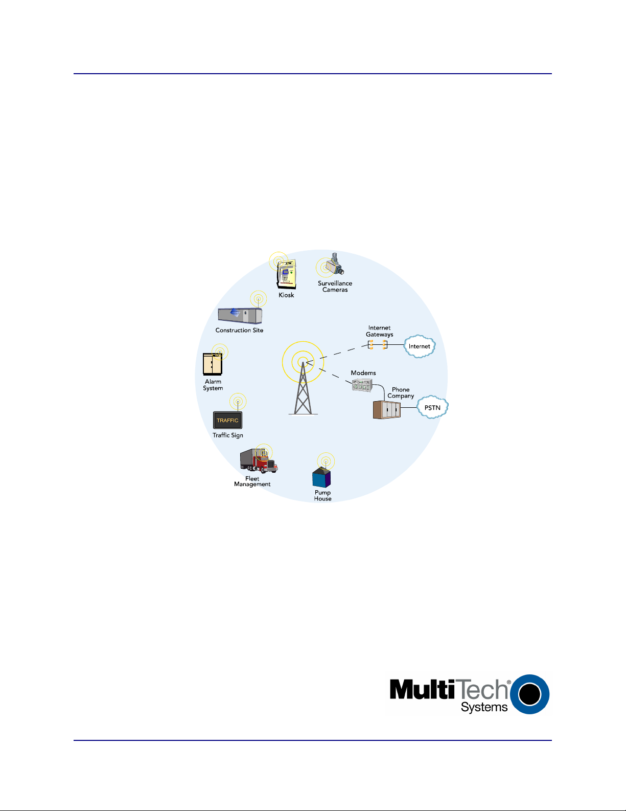
Application Example................................................................................................................................................ 6
Specifications........................................................................................................................................................... 7
Chapter 2 – Getting Started ......................................................................................................................... 8
Setup and Configuration .........................................................................................................................................8
1. Connections................................................................................................................................................8
2. Establish a Wireless Account......................................................................................................................8
3. Set the TCP/IP Address on Your PC ..........................................................................................................8
4. Login and Activate the Wireless Modem.....................................................................................................9
5. Configure the Ethernet-to-Wireless Modem Using the Web Management Software ..................................9
Navigating the Screens .........................................................................................................................................11
About the Front Panel LEDs..................................................................................................................................12
Ethernet LEDs ...............................................................................................................................................12
Modem LEDs .................................................................................................................................................12
Test Your Workstation...........................................................................................................................................12
Set Time and Date .................................................................................................................................................. 12
Shutdown Caution .................................................................................................................................................12
Using AT Commands............................................................................................................................................. 13
Query Your Modem's Operation ....................................................................................................................13
Set Up a Circuit-Switched Data (CSD) Connection for CDMA and GSM....................................................... 13
Answering a Circuit-Switched Data (CSD) Connection.................................................................................. 14
Chapter 3 – Using the Web Management Software................................................................................. 15
IP Setup...................................................................................................................................................................15
IP Setup > General Configuration .................................................................................................................. 15
IP Setup > HTTP Configuration .....................................................................................................................16
IP Setup > DDNS Configuration.....................................................................................................................17
IP Setup > SNTP Configuration .....................................................................................................................18
IP Setup > Static Routes................................................................................................................................19
IP Setup > Remote Configuration ..................................................................................................................20
PPP ....................................................................................................................................................................21
PPP > PPP Configuration ..............................................................................................................................21
PPP > Wakeup on Call ..................................................................................................................................22
Networks & Services..............................................................................................................................................23
Networks & Services > Network Configuration ..............................................................................................23
Networks & Services > Service Configuration................................................................................................24
Packet Filters.......................................................................................................................................................... 25
Packet Filters > Packet Filters. ......................................................................................................................25
Packet Filters > DNAT Configuration ............................................................................................................. 26
Packet Filters > Advanced .............................................................................................................................27
DHCP Server...........................................................................................................................................................28
DHCP Server > Subnet Settings.................................................................................................................... 28
DHCP Server > Fixed Addresses ..................................................................................................................29
Multi-Tech Systems, Inc. MultiModem Wireless Modem with Ethernet Interface (S000375A) 3
Page 4

Table of Contents
Tools ....................................................................................................................................................................29
Tools > Tools .................................................................................................................................................29
Tools > Service Status...................................................................................................................................30
Tools > Firmware Upgrade ............................................................................................................................30
Tools > Load Configuration............................................................................................................................ 31
Tools > Configuration Download.................................................................................................................... 31
Statistics & Logs....................................................................................................................................................32
Statistics & Logs > Ethernet........................................................................................................................... 32
Statistics & Logs > Serial ...............................................................................................................................32
Statistics & Logs > PPP ................................................................................................................................. 33
Statistics & Logs > PPP Trace.......................................................................................................................34
Statistics & Logs > SysInfo ............................................................................................................................35
Statistics & Logs > DHCP Stat....................................................................................................................... 35
Chapter 4 – Wireless Antenna................................................................................................................... 36
The Antenna ...........................................................................................................................................................36
GSM and CDMA Antenna..............................................................................................................................36
GSM Radio Characteristics............................................................................................................................36
CDMA Radio Characteristics .........................................................................................................................36
Antenna .........................................................................................................................................................36
Appendix A – Firmware Upgrade Using TFTP Client ............................................................................. 37
Appendix B – Multi-Tech Systems, Inc. Warranty and Repair Policies ................................................ 38
Multi-Tech Warranty Statement ............................................................................................................................38
Repair Procedures for U.S. and Canadian Customers ..................................................................................38
Repair Procedures for International Customers (Outside U.S.A. and Canada) .............................................39
Repair Procedures for International Distributors ............................................................................................ 39
Replacement Parts ........................................................................................................................................39
Appendix C – Waste Electrical and Electronic Equipment ....................................................................40
Index............................................................................................................................................................. 41
Multi-Tech Systems, Inc. MultiModem Wireless Modem with Ethernet Interface (S000375A) 4
Page 5

Chapter 1 – Introduction and Product Description
Chapter 1 – Introduction and
Product Description
This User Guide describes the MultiModem Wireless EDGE, GPRS, and CDMA modems with an Ethernet
Interface.
Product and Interface Descriptions
Ethernet Interface
The MultiModem wireless modems with an Ethernet interface provide shared Internet access with one IP
address. The built-in routing capabilities provide DHCP services and firewall security using Network Address
Translation. Due to the routing capabilities, these modems are sometimes called routers.
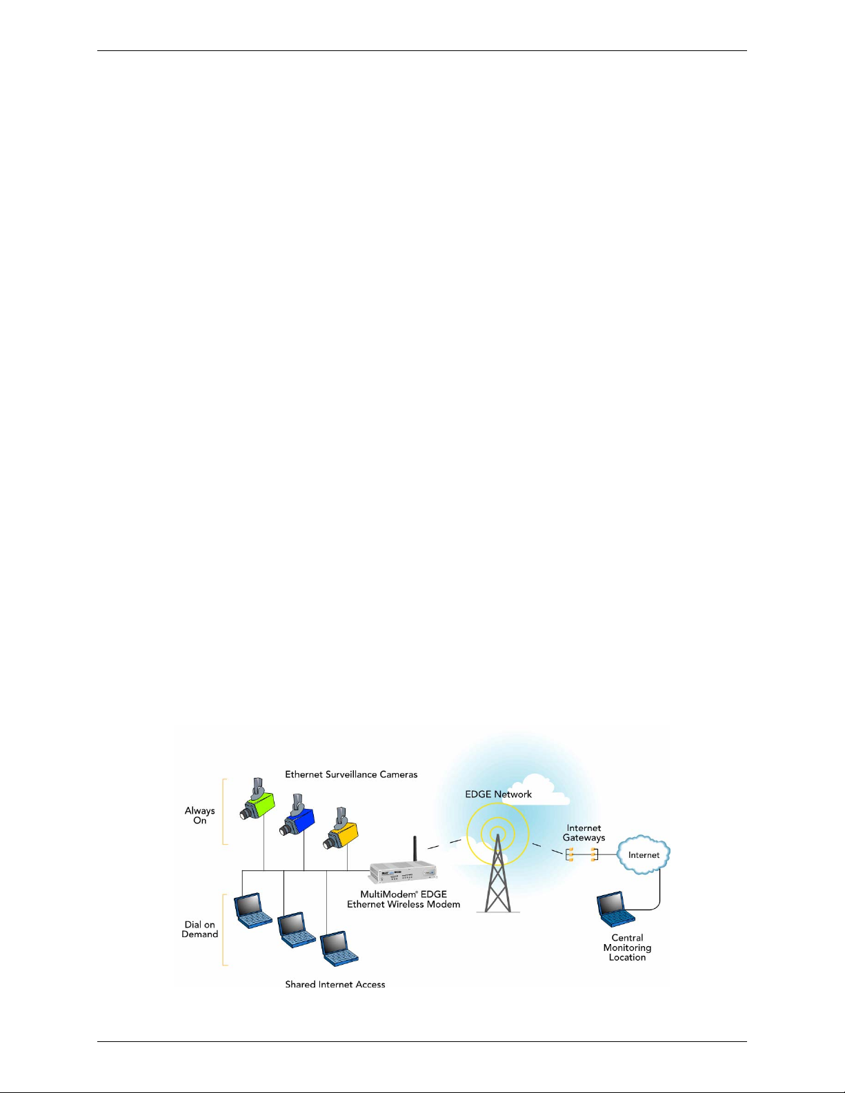
These modems support "always-on" network connection as well as "dial-on-demand" for Internet services. The
"always-on" network connection automatically establishes a wireless data connection and allows for around the
clock surveillance, monitoring or real-time data acquisition of any remote Ethernet device such as a Web
camera. If the data link is dropped in the event of poor reception or a complete loss of service, it will
automatically re-establish the data link. When configured for "dial-on-demand" the wireless modem only
accesses the Internet when data is present. This configuration is ideal for sharing Internet access among
networked PCs.
Software features include remote configuration, firmware upgrade, load configuration screen, and a save
configuration screen.
MultiModem EDGE
The MultiModem® EDGE wireless modem delivers some of the fastest cellular wireless data speeds utilizing
EDGE technology. It allows users to connect to the Internet and send and receive data up to three times faster
than possible with an ordinary GSM/GPRS network making it ideal for highly data-intensive multimedia
applications. The MultiModem EDGE wireless modem is equipped with quad-band GSM, which means it can be
used worldwide on all existing GSM networks.
AT Commands: The MultiModem EDGE wireless modem is configured using the EDGE AT
Commands. These commands are documented in the Reference Guide for the MultiModem
Wireless EDGE Modems, document number S000371x.
MultiModem GPRS
The MultiModem® GPRS wireless modem offers standards-based multi-band GSM/GPRS Class 10
performance. The ready-to-deploy, standalone data/fax/voice modem allows developers to add wireless
communication to products with a miniumum of development time and expense. The MultiModem® GPRS
wireless modem is base on industry-standard open interfaces and can be desktop or panel mounted.
AT Commands: The MultiModem GPRS wireless modem is configured using the GPRS AT
Commands. These commands are documented in the Reference Guide for the MultiModem
Wireless GPRS Modems, document number S000293x and also the Reference Guide for the
GSM IP Commands, document number S000333x.
MultiModem CDMA
The MultiModem® CDMA wireless modem offers standards-based multi-band CDMA200 1xRTT performance.
The ready-to-deploy, standalone data/fax/voice modem allows developers to add wireless communication to
products with a miniumum of development time and expense. The MultiModem
on industry-standard open interfaces and can be desktop or panel mounted.
AT Commands:The MultiModem CDMA wireless modem is configured using the CDMA AT
Commands. These commands are documented in the Reference Guide for the MultiModem
Wireless CDMA Modems, document number S000294x.
Multi-Tech Systems, Inc. MultiModem Wireless Modem with Ethernet Interface (S000375A) 5
®
CDMA wireless modem is base
Page 6
Chapter 1 – Introduction and Product Description
Safety Warnings
Ethernet Ports Caution
The Ethernet ports are not designed to be connected to a Public Telecommunication Network.
Handling Precautions
All devices must be handled with certain precautions to avoid damage due to the accumulation of static charge.
Although input protection circuitry has been incorporated into the devices to minimize the effect of this static build
up, proper precautions should be taken to avoid exposure to electrostatic discharge during handling and
mounting.
Safety Recommendations for Rack Installations
• Ensure proper installation in a closed or multi-unit enclosure by following the recommended installation
as defined by the enclosure manufacturer.
• If installing the wireless modem in a closed or multi-unit enclosure, ensure adequate airflow so that the
maximum recommended ambient temperature is not exceeded.
• Do not place the device directly on top of other equipment or place other equipment directly on top of
this device.
• Ensure that the device is properly connected to earth ground via a grounded power cord. If a power
strip is used, ensure that the power strip also provides adequate grounding.
• Ensure that the main supply circuit is capable of handling the load. See the power label on the device
for requirements.
• Maximum ambient temperature is 70 degrees Celsius.
• This device should be installed by properly qualified personnel.
• Only connect like circuits; e.g., connect SELV (Secondary Extra Low Voltage) circuits to SELV circuits
and TN (Telecommunications Network) circuits to TN circuits.
Ship Kit Contents
The wireless modem is shipped with the following:
• One Multi-Tech wireless modem with Ethernet interface.
• One power cord.
• One external power supply.
• One wireless modem antenna.
• Four rubber feet for desktop placement.
• One printed Quick Start Guide.
• Printed Activation Customer Notices (for Cingular, Sprint, Verizon networks, and general CDMA
activation).
• One product CD that provides documentation and Adobe Acrobat Reader.
Application Example
Multi-Tech Systems, Inc. MultiModem Wireless Modem with Ethernet Interface (S000375A) 6
Page 7

Chapter 1 – Introduction and Product Description
Specifications
Features EDGE Modems GPRS Modems CDMA Modems
Performance EDGE: E-GPRS Class 10,
GPRS: Class 12
Band,
Frequency
Packet Data
CircuitSwitched Data
Short Message
Services-SMS
Fax Class 1 Group 3 GSM Class 1 and Class 2 Group 3 Class 2.0 Group 3
Voice Features
Antenna
Connectors
SIM Connector Standard 3V SIM receptacle Standard 3V SIM receptacle
Interface
Connectors
Power
Connectors
Voice
Connectors
Power
Requirements
Physical
Description
Operating
Environment
Certifications CE Mark, R&TTE
Miscellaneous AT Command Compatible
Quad-band GSM
850/900/1800/1900 MHz
EDGE: E-GPRS Up to 240K bps,
coding scheme MCS 1-9, mobile
station Class B, LLC layer, 4 time
slots
GPRS: Full PBCCH support, coding
scheme 1-4, mobile station Class B
Up to 9600 bps transparent and
non-transparent, asynchronous
Text & PDU, Point-to-Point MO &
MT, cell broadcast
Half rate (HR), Full rate (FR),
Enhanced full rate (EHR), Adaptive
multi rate (AMR), hands free echo
cancellation, noise reduction
RF Antenna: 50 ohm SMA (female
connector)
Ethernet Model: RJ-45,
10BaseT/100BaseTX, 802.3
Ethernet Model: 2.5mm miniature
screw
Ethernet Model: RJ-9 4-pos
modjack
5V to 32 VDC 5V to 32 VDC 5V to 32 VDC
Ethernet Model:
2.8" L x 6.4" W x 1.2" H; 11.5 oz.
(7.1 cm x 16.3 cm x 3.0 cm; 326G)
0 to +50° C 0 to +50° C 0 to +50° C
EMC: FCC Part 2, 15 Class A, 22,
24; EN 55022, EN 55024
Safety: cUL, UL 60950; EN 60950
Network: PTCRB
Desktop or panel mounting
Carrier approved
Numerous LEDs provide status
Two year warranty
GPRS Class 10 CDMA2000 1xRTT
Dual-band 850/1900 or 900/1800
MHz GSM/GPRS
Up to 85.6K bps, coding schemes
CS1 to CS4
Up to 14.4K bps transparent and
non-transparent, asynchronous
Text & PDU, Point-to-Point, cell
broadcast
Half rate (HR), Full rate (FR),
Enhanced full rate (EHR), echo
cancellation, noise reduction
(option), telephony and Dual Tone
Multi Frequency (DTMF)
transmission, emergency calls
RF Antenna: 50 ohm SMA (female
connector)
Ethernet Model: RJ-45,
10BaseT/100BaseTX, 802.3
Ethernet Model: 2.5mm miniature
screw
NA NA
Ethernet Model:
2.8" L x 6.4" W x 1.2" H; 11.5 oz.
(7.1 cm x 16.3 cm x 3.0 cm; 326G)
CE Mark, R&TTE
EMC: FCC Part 2, 15 Class A, 22,
Safety: cUL, UL 60950; EN 60950
Network: PTCRB
AT Command Compatible
Desktop or panel mounting
Carrier approved
Numerous LEDs provide status
Two year warranty
24; EN 55022, EN 55024
Dual-band 800/1900 MHz CDMA;
800 MHz with R-UIM support
Up to 153.6K bps forward and
reverse
IS-95A, IS 95B up to 14.4K bps
forward and reverse
Text & PDU, Point-to-Point, cell
broadcast
Telephony and Dual Tone Multi
Frequency (DTMF) functionality,
AMPS Voice, QCELP (13K), echo
cancellation
RF Antenna: 50 ohm SMA (female
connector)
Ethernet Model: RJ-45,
10BaseT/100BaseTX, 802.3
Ethernet Model: 2.5mm miniature
screw
Ethernet Model:
2.8" L x 6.4" W x 1.2" H; 11.5 oz.
(7.1 cm x 16.3 cm x 3.0 cm; 326G)
EMC: FCC Part 2, 15 Class A, 22,
24; EN 55022, EN 55024
Safety: cUL, UL 60950; EN 60950
Network: PTCRB
AT Command Compatible
Desktop or panel mounting
Carrier approved
Numerous LEDs provide status
Two year warranty
Over-the-air activation
CDG 1 and 2 network certified
Multi-Tech Systems, Inc. MultiModem Wireless Modem with Ethernet Interface (S000375A) 7
Page 8
Chapter 2 – Getting Started
Setup and Configuration
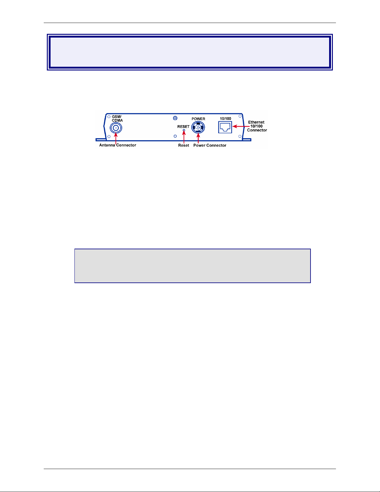
1. Connections
In order to operate your wireless modem, you must make the proper Power and Ethernet connections.
• Using an RJ-45 Ethernet cable, connect the 10/100 jack to an internal network switch or hub.
• Plug one end of the power cord into the device and the other end onto a live power outlet.
Notes:
• The PWR LED lights after power-up.
• Pressing and holding the Reset button for 5 seconds will restore all factory default settings.
2. Establish a Wireless Account
Obtain a wireless account through a Wireless Service Provider. This will allow you to use the service
provider's network; for example, Cingular, Sprint, and Verizon.
Contact Multi-Tech, a certified national activation agent for Cingular and Sprint, to set up one of these
accounts.
For Verizon and other accounts, contact their activation agents directly.
Chapter 2 – Getting Started
See the Cingular, Sprint, Verizon, and general Customer Activation Customer Notices
included with your modem for a list of the information you must give to the activation agent.
You will receive, depending upon your provider, one or two phone numbers and a service
programming code or lock code. Write these numbers down as you will have to use them to
configure the wireless modem.
If you have any questions or want to set up your account, contact Multi-Tech Systems, Inc. at:
800-972-2439 or 763-717-5863.
3. Set the TCP/IP Address on Your PC
Once the wireless account is established and the modem is properly connected, set up the TCP/IP address
on your PC, if not previously set.
3.1 Open the PC's Control Panel.
3.2 Select Networks or Network Connections.
3.3 Under Protocols, select TCP/IP.
3.4 Under Properties, choose one of the following:
∗ Check Obtain IP Address Automatically and Obtain DNS Server Address Automatically. If
you check these, then the DHCP function obtains the IP Address automatically from the Ethernet
wireless modem, or
∗ Check Use the Following IP Address and Use the Following DNS Server Address. If you
check these, then enter the following addresses:
IP Address: 192.168.2.2
Subnet Mask: 255.255.255.0
Gateway: 192.168.2.1
Specify a DNS Server. For example, 205.171.3.65
Multi-Tech Systems, Inc. MultiModem Wireless Modem with Ethernet Interface (S000375A) 8
Page 9
Chapter 2 – Getting Started
4. Login and Activate the Wireless Modem
4.1 From the workstation, open the DOS screen by clicking the Start button and selecting Programs >
Accessories > Command Prompt.
4.2 At the C:\> prompt, enter Telnet 192.168.2.1 5000
Note: 5000 is the port number.
4.3 At Login, enter the user name admin.
4.4 At Password, enter the password admin.
4.5 The PC is now ready to issue the AT commands that will configure the wireless modem.
Do not exit the DOS screen. You can enter the AT commands that configure your modem
using the DOS prompt. Continue with Step 4.6.
4.6 Activate wireless functionality using AT commands.
Refer to the Customer Activation Notices again and enter the AT commands required
by your service provider. Each provider has a certain number of commands that must be
entered. For example, Sprint has eight command steps and Verizon has four command
steps.
5. Configure the Ethernet-to-Wireless Modem Using the
Web Management Software
You are now ready to configure the Ethernet-to-wireless modem. This is accomplished by using the
modem's factory-installed Web Management software, which is accessed by opening a Web Browser,
entering the Gateway Address, and completing the login.
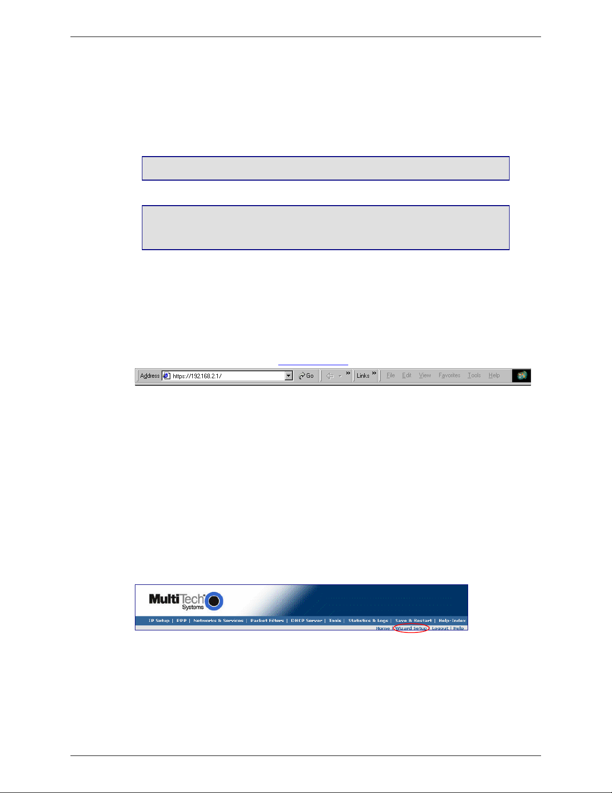
5.1 Open a Web Browser
From the workstation, open a Web Browser.
Type the default Gateway Address: http://192.168.2.1
5.2 Login
After entering the Address, the Login screen displays.
• Type the default User name: admin (all lower-case).
• Type the default password: admin (all lower-case).
Note: The User name and Password are case-sensitive (both must be typed in lower-case). If
Windows displays the AutoComplete screen, you may want to click No to tell the Windows OS not
to remember the password; this helps maintain PC security.
• Click the Login button. The Web Management Home screen displays.
5.3 Use the Setup Wizard for Quick Configuration
A quick way to configure the modem is to use the Setup Wizard in the Web Management software.
You can set/enable additional features and functions using the complete Web Management software
program. This software is explained in detail in Chapter 3.
• To begin configuration, click the Wizard Setup button located under the menu bar.
•
After clicking the Wizard Setup button, the Wizard screen displays.
Multi-Tech Systems, Inc. MultiModem Wireless Modem with Ethernet Interface (S000375A) 9
Page 10
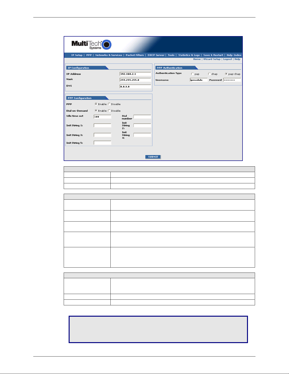
5.4 How to Use Setup Wizard
The following is a screen shot of the Setup Wizard. See the tables below for setup information.
Chapter 2 – Getting Started
IP Configuration
IP Address
Mask
DNS
PPP Configuration
PPP
Dial-onDemand
Idle Time Out
Dial Number
Init String
PPP Authentication
Authentication Type
User Name
Password
IP Address 192.168.2.1 defaults into this text box.
Enter the IP Mask 255.255.255.0
Enter the primary DNS IP address for the system. Default is 0.0.0.0
Click Enable to activate PPP.
Click Disable if you do not want this protocol activated.
Click Enable to activate dial-on-demand feature.
If you Disable dial-on-demand, the modem always stays connected.
Sets the amount of time the PPP link stays active before disconnecting.
Setting the value to zero causes the link to stay active continuously.
Enter the dial number. This number connects you to the Internet.
For GSM/GPRS, the number is *99***1#.
For CDMA, the number is #777
You can set up to 5 modem initialization strings.
For GSM/GPRS: Enter the Access Point Name by typing
AT+CGDCONT=1,"IP","<APN>"
The APN is assigned by your wireless service provider.
Click the button corresponding to the authentication protocol you want to
use to negotiate with the remote peer. PAP, CHAP, or PAP-CHAP.
Default = PAP-CHAP
Enter the PPP User Name. This name authenticates the remote peer.
Enter the PPP Password. This password authenticates the remote peer.
Important Note about Submit and Save & Restart: Click the Submit button located at the
bottom of most screens in order to save any changes you make. Then you must click the
Save & Restart button in order for your settings to take effect. Save & Restart does not
have to be executed after each screen; you can change and Submit several screens, and
then click Save & Restart. The Save & Restart button is located on the Menu bar.
Multi-Tech Systems, Inc. MultiModem Wireless Modem with Ethernet Interface (S000375A) 10
Page 11
Chapter 2 – Getting Started
Navigating the Screens
This section explains the menu structure and the navigation buttons.
Menu Bar
IP Setup: Sets up a General Configuration, HTTP, DDNS, SNTP, Static Routes, and Remote Configuration.
PPP: Sets up the PPP authentication, dial-on-demand, modem authentication, and Wakeup on Call.
Networks & Services: Defines networks and services to make them available to other functions such as
allowed packet filters, DHCP Server, and Statistics & Logs.
Packet Filters: Defines filter rules, DNAT configuration, and ICMP rules.
DHCP Server: Configures the DHCP server settings.
Tools: Sets DDNS Force Update and Reset Modem, displays Service Status, and provides screens for
Firmware Upgrade, Load Configuration, and Save Configuration.
Statistics & Logs: View all the statistics and logs maintained by the modem.
Save & Restart: Click this to Save your settings and reboot your PC.
Help Index: Click this to access the Help text.
Screen Parts
Menu Bar Submenu Title Submenu List
Screen Buttons
Screen Name
Screen Input Area
Screen Buttons
Home: Click this button to return to the Home screen.
Wizard Setup: Click this button to display the Wizard Setup screen on which you can quickly set up your
wireless modem with basic configuration settings.
Logout: Click this button to Logout and return to the login screen.
Help: Click this button to display the Help text.
Submenus
The submenus display on the left side of the screen.
The following table shows the sub-menu selections under each main menu category.
IP Setup PPP Networks &
Services
General Config.
HTTP Config.
DDNS Config.
SNTP Config.
Static Routes
Remote Config.
PPP Config.
Wakeup on Call
Network Configuration
Service Configuration
Packet Filters DHCP Server Tools Statistics
Packet Filters
DNAT Config.
Advanced
Subnet Settings
Fixed Addresses
Tools
Service Status
Firmware Upgrade
Load Config.
Save Config.
& Logs
Ethernet
Serial
PPP
PPP Trace
SysInfo
DHCP Stat
Multi-Tech Systems, Inc. MultiModem Wireless Modem with Ethernet Interface (S000375A) 11
Page 12
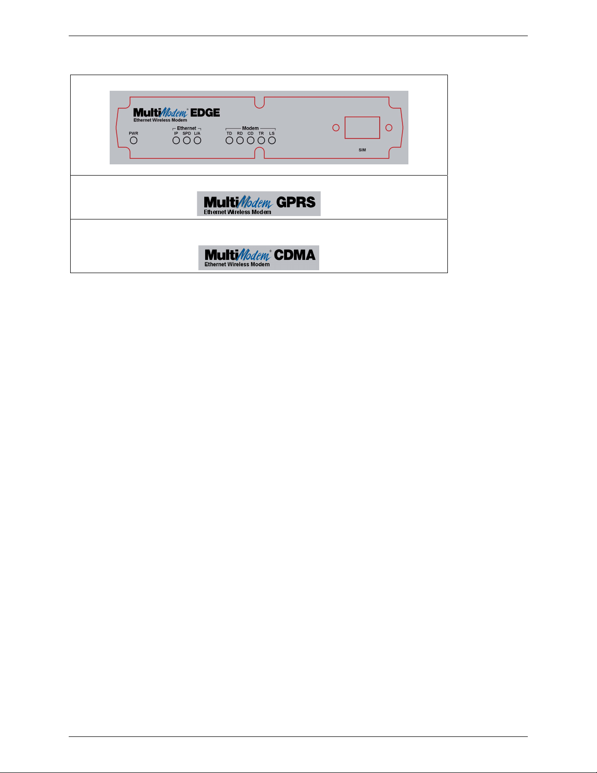
About the Front Panel LEDs
The Ethernet EDGE has 3 Ethernet LEDs and 5 modem LEDs.
Chapter 2 – Getting Started
The Ethernet GPRS has the same LEDs as the EDGE modem and a SIM card slot.
The Ethernet CDMA has the same LEDs as the EDGE modem. It does not, however, have a
SIM card slot.
Ethernet LEDs
IP IP FUNCTION. This LED blinks when the IP function of the modem/router is operating normally. It shows a
steady light when powering-up, initializing, or flashing the firmware.
SPD SPEED. This LED lights when the Ethernet is linked at 100 Mbps. If it is not lit, the Ethernet is linked at 10
Mbps.
L/A LINK ACTIVITY. This LED blinks when there is transmit and receive activity on the Ethernet. It shows a
steady light when there is a valid Ethernet connection.
Modem LEDs
TD TRANSMIT DATA. This LED blinks when the modem is transmitting data to your wireless carrier.
RD RECEIVE DATA. This LED blinks when the modem is receiving data from your wireless carrier.
CD CARRIER DETECT. This LED lights when the modem detects a valid carrier signal from a wireless carrier.
TR (DATA) TERMINAL READY. This LED lights when the modem is trying to establish a wireless connection.
LS LINK STATUS. This LED blinks when there is a valid wireless signal. When it is on or off, the wireless
strength is low.
Test Your Workstation
Test your workstation to see that it can access the Internet. If a connection is established, then the settings have
been entered correctly. Note: If you had changed your IP Address, be sure to enter the new one when you access
the Internet.
Set Time and Date
The date and time must be set using the Web Management software.
The time and date set in IP Setup will not be correct unless SNTP client is enabled and you have a live Internet
connection. See SNTP client.
Shutdown Caution
Never unplug the power until after you have performed the Save & Reset process. If the setup changes are not
properly saved before unplugging the power, data could be lost.
Multi-Tech Systems, Inc. MultiModem Wireless Modem with Ethernet Interface (S000375A) 12
Page 13

Chapter 2 – Getting Started
Using AT Commands
Important Note: Before you can use these commands, you must complete Steps 4.1 through 4.4 on page 9.
Query Your Modem's Operation
1. Check the signal quality.
• Type AT+CSQ
Modem responds with the received signal strength (rssi).
2. Check the identity of the modem.
Use command: ATI (AT is followed by the capital letter i).
• Type ATI0 (The command ends in a zero).
Manufacturing data displays: Wavecom Modem 800 1900
• Type ATI3
Software version displays. Ex: S/W VER: xxxxx
• Type ATI6
Capability data displays. Ex: +CGSM, +CIS707, ...
3. Check the network registration and roaming status.
• Type AT+CREG?
The modem will respond in one of the following ways:
+CREG: 0,0 (this tells you the modem is not registered on any network)
+CREG: 0,1 (this tells you the modem is registered on the home network)
Set Up a Circuit-Switched Data (CSD) Connection for
CDMA and GSM
+CREG: 0,5 (this tells you the modem is registered on a network but it is roaming)
A Circuit-Switched Data Connection makes the wireless modem work like a regular analog modem. You
must have CSD service in order to make a CSD call.
1. Establish a Connection: Using HyperTerminal or a terminal application, establish a CSD connection
by entering command: ATD<phone number>
Notes:
• The phone number you are calling is entered between the displayed brackets. Do not type
additional brackets. Ex: type only ATD 8585551212 between brackets.
• This command tells the modem to inform the wireless network that you are initiating a CSD modem
call. If you are dialing to another modem, the remote modem should answer and a connection
between the two modems will be established. If you include a semi-colon (;) at the end of the
2.
dialing string, the modem will instead initiate a Voice call to the phone number dialed.
Disconnect: Use the following commands:
+++ Wait about 2 seconds to see OK.
Then type: ATH
Note: +++ is the escape sequence and ATH is the Hang-up command.
Multi-Tech Systems, Inc. MultiModem Wireless Modem with Ethernet Interface (S000375A) 13
Page 14

Chapter 2 – Getting Started
Answering a Circuit-Switched Data (CSD) Connection
A Circuit-Switched Data Connection makes the wireless modem work like a regular analog modem. You
must have CSD service in order to answer a CSD call.
For CDMA
Establish A Connection:
Using HyperTerminal or a terminal application, enter the following command:
AT+CICB=0 <cr> This sets the modem to answer in data mode.
Then call into the modem by dialing the number provided by your carrier.
Answer a Call: Enter ATA <cr> when you see on the terminal screen that RING responses are
coming through.
Set Auto-Answer: Enter ATS0=x (where x is the number of rings). This sets the modem to auto-
answer. The call is answered after x number of rings.
Call into the modem by dialing the number provided to you by the carrier.
Disconnect: Use the following commands:
+++ Wait about 2 seconds for OK.
Then type: ATH
For GSM
There are three phone numbers for GSM: the voice number, the data number, and the fax number.
All are provided by the carrier. To answer a call:
Establish A Connection:
Call into the modem by dialing the data number provided by your carrier.
Answer a Call: When you see the RING responses on the terminal screen, enter ATA <cr> to
answer the call.
Set Auto-Answer: Enter ATS0=x (where x is the number of rings). This sets the modem to auto-
answer. The call is answered after x number of rings.
Then call into the number provided to you by the carrier.
Disconnect: Use the following commands:
+++ Wait about one second to see OK.
Then type: ATH
Multi-Tech Systems, Inc. MultiModem Wireless Modem with Ethernet Interface (S000375A) 14
Page 15

Chapter 3 – Using the Web Management Software
Chapter 3 – Using the Web
Management Software
This section describes each screen in the Web Management software.
Important Note about Submit and Save & Restart: Click the Submit button located at the bottom of most screens
in order to save any changes you make. Then you must click the Save & Restart button in order for your settings to
take effect. Save & Restart does not have to be executed after each screen; you can change and Submit several
screens, and then click Save & Restart. The Save & Restart button is located on the Menu bar.
IP Setup
IP Setup > General Configuration
In General Configuration, you can set the general system-based parameters.
Multi-Tech Systems, Inc. MultiModem Wireless Modem with Ethernet Interface (S000375A) 15
Page 16

General Configuration
Date and Time: The system date and time display in these formats: DD/MM/YYYY / HH:MM:SS. SNTP Client
must be enabled and you must have a live Internet connection for the date and time to display correctly.
IP Configuration
Enter the following addresses for the Ethernet interface. Defaults are 0.0.0.0
IP Address (Default = 192.168.2.1), Mask, Default Gateway, Primary DNS, Secondary DNS.
Auto Dialout Configuration
Auto Dialout: Check the box to enable/disable Auto Dialout. Default = Enable.
Raw Dialout: Check the box to enable/disable raw mode for an Auto Dialout session. Default = Disable.
Auto Dialout Login: Check the box to enable or disable Auto Dialout Login feature. Default = Enable.
Auto Dialout Port: Enter the serial Auto Dialout Port number. Default = 5000.
Handle EIA Signal: Check the box to enable/disable the EIA standard signal characteristics (time and
duration) used between different electronic devices.
Inactivity: Enter the time in seconds that the auto dialout session will stay active before going inactive.
Syslog Configuration
Syslog: Check the box to enable or disable Syslog. Default = Disable.
Syslog Server IP Address: If a Remote Syslog Server IP Address is specified, the syslog feature acts as a
remote Syslog.
Auto Discovery
Autodiscovery: Check the box to enable or disable Autodiscovery to broadcast (MAC level), the MAC
Address, IP Address, and DHCP information to the configured server port. Default = Enable.
Server Port: Enter the Server Port Number. Default port is 1020.
Broadcast Timer: Enter the amount of time in seconds for the auto-discovery packet granularity of periodic
broadcasting. Default is 10 seconds.
TFTP Configuration
Firmware Upgrade: Check the box to enable or disable the firmware upgrade. Default is Disable.
Submit Button
Click the Submit button to save these settings. You must click Save and Restart once you have completed
and submitted all the screens on which you have made changes.
IP Setup > HTTP Configuration
Chapter 3 – Using the Web Management Software
HTTP Configuration
HTTP Port: Enter the port number for the HTTP server to listen for requests. Default is 80.
Authentication
User Name: Enter the User Name that can access to the Web Management software. Default is admin.
Password: Enter the Password for access to the Web Management software. Default is admin.
Note: You should change the password to one of your choosing. A password can be up to 12 characters.
Password Caution: Use a safe password! Your first name spelled backwards is not a
sufficiently safe password; a password such as xfT35$4 is better. It is recommended
that you change the default password to better protect the security of your modem.
Submit Button
Click the Submit button to save these settings. You must click Save and Restart once you have completed
and submitted all the screens on which you have made changes.
Multi-Tech Systems, Inc. MultiModem Wireless Modem with Ethernet Interface (S000375A) 16
Page 17

Chapter 3 – Using the Web Management Software
IP Setup > DDNS Configuration
The DDNS Client is used to update the IP address of the modem/router in a DDNS server for the configured domain
name whenever the IP Address changes, thus, leaving the domain name to be pointing to the current IP Address of the
modem/router all the time.
General
DDNS: Check the Enable or Disable box to indicate whether or not you want a DDNS Client.
Default = Disable.
User Check IP: Check the Enable or Disable box. If enabled, the program will query the server to
determine the IP address before it performs the DDNS update (the IP address is still assigned
by the wireless provider and the DDNS will be updated based on the address returned by
Check IP Server). If disabled, the program will perform the DDNS update using the IP address
that it obtains from the PPP link.
Check IP Server: Enter the IP Server name that will get the current assigned WAN IP Address to the
firewall.
Check IP Port: Enter the port number of the IP Server. Default is 80.
Server: Enter the name of the IP Server.
Port: Enter the port number of the IP Server.
Max Retries: Enter the maximum number of tries that will be allowed to access the IP Server.
Update Interval: Enter the intervals in days that the IP Address will be updated for the DDNS server.
System: Sets the system as Dynamic or Custom.
System Domain: Enter the domain name of the system.
Authentication
User Name: Enter the User Name that can access the DDNS Server.
Password: Enter the Password that can access the DDNS Server.
Submit Button
Click the Submit button to save these settings. You must click Save and Restart once you have
completed and submitted all the screens on which you have made changes.
Multi-Tech Systems, Inc. MultiModem Wireless Modem with Ethernet Interface (S000375A) 17
Page 18

IP Setup > SNTP Configuration
Chapter 3 – Using the Web Management Software
General Configuration
SNTP Client: Enable or disable the SNTP Client to contact the configured server on the UDP port 123
and set the local time. Default is Disable.
Server: Enter the SNTP server name or IP address to which the SNTP Client must contact in
order to update the time. No default.
Polling Time: Enter the polling time at which the SNTP client requests the server to update the time.
Default is 300 minutes. Time must be entered in minutes.
Time Zone Configuration
Time Zone: Enter your time zone. Default = UTC (Universal Coordination).
See the following Web site for Time Zone information:
http://wwp.greenwichmeantime.com/info/timezone.htm
Time Zone Offset: Enter +/- hh:mm. Default = +00:00. Offset is the amount of time varying from the
standard time of a Time Zone.
Daylight Configuration
Daylight Saving: Enables/disables Daylight Saving mode. Default is Enable.
Daylight Saving Offset: Set the offset to use during Daylight Saving mode. Default is +60 minutes.
Enter the time in + / - minutes.
Multi-Tech Systems, Inc. MultiModem Wireless Modem with Ethernet Interface (S000375A) 18
Page 19

Chapter 3 – Using the Web Management Software
Daylight Saving Start Time
Start Ordinal: Set the start ordinal to use during Daylight Saving mode. Options are
first/second/third/fourth/last. Default is first.
Daylight Saving time usually starts at the same time on the same day of the week in the
same month every year. Each day of the week occurs four or five times a month.
Therefore, you will be selecting the week in which daylight saving time starts: the first,
second, third, fourth or the last of the month. In the U.S.A., daylight saving time starts at
2:00 a.m. on the first Sunday in April.
Start Month: Set the start month to use during Daylight Saving mode. Default is April.
Start Day: Set the start weekday to use during Daylight Saving mode. Default is Sunday.
Start Time: Set the start time to use during Daylight Saving mode. Default is 02:00 (hh:mm).
Daylight Saving End Time
End Ordinal: Set the end ordinal to use during Daylight Saving mode. Select the week in which
daylight saving time ends. Options are first/second/third/fourth/last. Default is last.
End Month: Set the end month to use during Daylight Saving mode. Default is October.
End Day: Set the end weekday to use during Daylight Saving mode. Default is Sunday.
End Time: Set the end time to use during Daylight Saving mode. Default is 02:00 (hh:mm).
Submit Button
Click the Submit button to save these settings. You must click Save and Restart once you have
completed and submitted all the screens on which you have made changes.
IP Setup > Static Routes
Routing information is used by every computer connected to a network to identify whether it is sending a data packet
directly to the firewall or passing it on to another network. The options to Delete or Edit a route after it has been
defined and added are available by using the table at the bottom of the screen.
Add Static Routes
Static Route: Select a static route from the drop down list box, and then click the Add button.
Add Button: After clicking the Add button, the new route is added and will display at the bottom of
the screen.
Important Note:
The
Static Route screen will not display until the network is defined under Networks & Services.
Multi-Tech Systems, Inc. MultiModem Wireless Modem with Ethernet Interface (S000375A) 19
Page 20

Chapter 3 – Using the Web Management Software
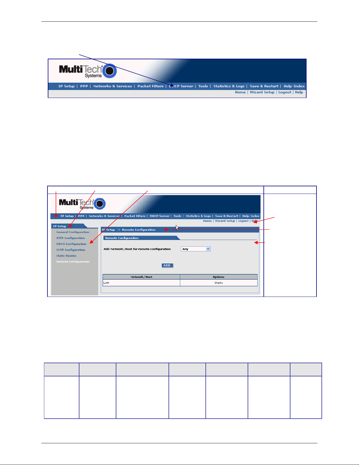
IP Setup > Remote Configuration
Remote Configuration
Add Network/Host for Remote Configuration:
Select a network or host from the drop down box. The choices are Any, LAN, and WAN
Interface. Choose all that apply. Click the Add button after each selection.
Add Button: After clicking the Add button, the network or host is added and displays at the bottom of
the screen.
Delete: You will have the option to delete Any and WAN Interface.
Multi-Tech Systems, Inc. MultiModem Wireless Modem with Ethernet Interface (S000375A) 20
Page 21

PPP
PPP > PPP Configuration
Chapter 3 – Using the Web Management Software
PPP General
PPP Enable/disable PPP. Default is Enable.
Dial-on-Demand: Enable/disable Dial-on-Demand. Default is Enable. If you disable it, the modem will
always stay connected.
Idle Time Out: Set the amount of idle time that will pass before the modem will timeout. Default is
180 seconds.
Connect Time Out: Set the amount of seconds to wait for a connection while in receive mode before
timing out.
Dialing Max Retries: Enter the number of dialing retries allowed. Default is zero, which means an infinite
number is allowed. Range 0 to 100.
Authentication
Authentication Type: Set the authentication protocol type that will negotiate with the remote peer:
pap/chap/pap-chap. Default is pap-chap.
User Name: Enter the User Name with which the remote peer will authenticate. Default is
ipmodule.
Password: Enter the Password with which the remote peer will authenticate. Default is ipmodule.
Multi-Tech Systems, Inc. MultiModem Wireless Modem with Ethernet Interface (S000375A) 21
Page 22
Chapter 3 – Using the Web Management Software
ICMP Keep Alive Check
Keep Alive Check: Enable/disable the Keep Alive Check. Default is disable.
Host Name: Enter the Host Name.
Interval: Default is 30 seconds.
Count: Default is 10.
Modem Configuration (Refer to the Customer Activation Notices included with the product for proper
information to enter).
Baud Rate: Set the serial baud rate. Default is 115200.
Dial Number: Set the dial number to be dialed. Default is NULL.
For EDGE or GPRS the number is *99***1#.
For CDMA the number is #777.
Dial Prefix: Set the modem dial prefix. Default is ATDT.
Connect String: Set the modem connect string. Default is CONNECT.
Init String: Configure the modem init strings. Init-num can range from 1-5.
Submit Button
Click the Submit button to save these settings. You must click Save and Restart once you have
completed and submitted all the screens on which you have made changes.
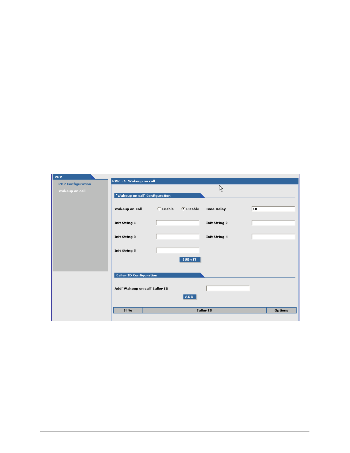
PPP > Wakeup on Call
The Wakeup on Call feature allows the modem to wake up and initiate a connection when there is an incoming call. If
you desired some security with this feature, you can setup the modem to wake up based on Caller ID instead of
allowing all incoming to wakeup the modem. This will reduce the cost for a modem to be online and available 24/7.
“Wakeup on Call” Configuration
Wakeup on Call: Enable/disable Wakeup on Call. Default is disable.
Time Delay: Enter the amount of time that will pass between the ring of an incoming call and the
initiated connection.
Init Strings: Configure the modem initialization strings. Init-num can range from 1-5.
Caller ID Configuration
Add “Wakeup on Call” Caller ID: To add Caller ID to the Wakeup-on-Call function, enter the Caller ID to
be allowed to wakeup the modem. After entering the Caller ID, click the Add button.
The Caller ID displays at the bottom of screen. You can enter any number of IDs you
desire. A Caller ID can be edited or deleted using Options, which will be available
once a Caller ID is displayed.
Submit Button
Click the Submit button to save these settings. You must click Save and Restart once you have completed
and submitted all the screens on which you have made changes.
Multi-Tech Systems, Inc. MultiModem Wireless Modem with Ethernet Interface (S000375A) 22
Page 23

Chapter 3 – Using the Web Management Software
Networks & Services
Networks & Services > Network Configuration
Networks or Hosts can be added here. The options to Delete or Edit a network after it has been defined and added
are available by using the table at the bottom of the screen.
Network Configuration
Enter the Name, IP Address, and Mask for a new Network or Host.
Notes:
• A Network/Host Name cannot be edited.
• A Network/Host cannot be deleted if it is used in another configuration.
• Network/Host changes are reflected in all the configurations in the Web Management software where
they are used.
• A Network/Host added here will be displayed in the following sections: Static Routes, DNAT, and
Packet Filters.
Name: Enter the name of the Network/Host. The same address-mask pair should not already
IP Address: Enter the IP Address of the Network/Host. The same address-mask pair should not
Subnet Mask: Enter the Network Mask of the Network/Host. For Host addresses, the mask is entered
Add Button: Click the Add button. The defined network is added and will display at the bottom of the
be present in the list displayed.
already be present in the list displayed.
as 32.
screen.
Multi-Tech Systems, Inc. MultiModem Wireless Modem with Ethernet Interface (S000375A) 23
Page 24
Chapter 3 – Using the Web Management Software
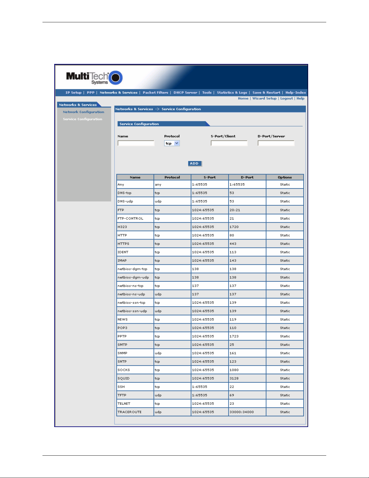
Networks & Services > Service Configuration
On this screen you can specify the standard set of well known services available on the system. These services
enable the configuration of the user defined services. The options to Delete or Edit a service after it has been defined
and added are available by using the table at the bottom of the screen.
Multi-Tech Systems, Inc. MultiModem Wireless Modem with Ethernet Interface (S000375A) 24
Page 25
Chapter 3 – Using the Web Management Software
Service Configuration
Enter the Name, Protocol, Source Port/Client, and Destination Port/Server for the new Service.
Notes:
• A Service Name cannot be edited.
• A Service cannot be deleted if it is used in another configuration.
• Services changes are reflected in all the configurations in the Web Management software where they
are used.
• Services added here will be displayed in the following sections: DNAT, Packet Filters.
Name: Enter the name of the Service. It has to be unique.
Protocol: Enter the type of protocol (ITCP, UDP).
Source Port: Enter the Source Port for this service.
Destination Port: Enter the name of the Destination Port for the service.
Add Button: Click the Add button. The new service is added and will display on the screen.
Packet Filters
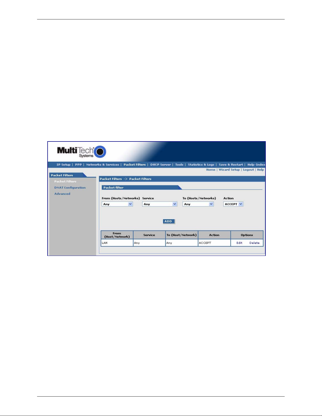
Packet Filters > Packet Filters.
You can Delete or Edit a packet filter rule after it has been defined and added by using the table at the bottom of the
screen.
Packet Filter
From (Host/Networks): Enter the network/host from which the packet must originate for the filter rule to
match. The Any option, which matches all IP addresses regardless of whether they are
officially assigned addresses or private addresses, may also be entered. The
network/host must be pre-defined in the Networks section.
Service: Enter the service that is to be matched with the filter rule. These services must be pre-
defined in the Services section. These services precisely define the traffic to be filtered.
To (Host/Networks): Enter the network/host to which the packet must send for the filter rule to match. The
Any option, which matches all IP addresses regardless of whether they are officially
assigned addresses or private addresses, may also be entered. The network/host must
be pre-defined in the Networks section.
Action: Enter the action that the packet filter executes if the rule matches any traffic traversing
the firewall. Types of actions defined are:
Accept: Allows/accepts all packets that match this rule.
Reject: Blocks all packets that match this rule. The host sending the packet will be
informed that the packet has been rejected.
Drop: Blocks all packets that match this rule, but the host is not informed; i.e., this is a
silent drop.
Log: Packets matching the rule; i.e., the corresponding source address, destination
address, and service will be logged.
Add Button: Click the Add button. The defined packet filter rule is added and will display at the
bottom of the screen.
Multi-Tech Systems, Inc. MultiModem Wireless Modem with Ethernet Interface (S000375A) 25
Page 26

Chapter 3 – Using the Web Management Software
Packet Filters > DNAT Configuration
Destination Network Address Translation (DNAT) is a process that allows the placing of servers within the protected
network and making them available for a certain service to the outside world. The DNAT process running of the
wireless modem/router translates the destination address of incoming packets to the address of the real network
server on the LAN. The packets are then forwarded.
You can Delete or Edit a DNAT rule after it has been defined and added by using the table at the bottom of the
screen.
Important Note: When adding rules, at least one host must be defined in the Network Configuration section.
DNAT Configuration
Source: Enter the original target network or host of the IP packets that are to be re-routed.
The network/host must be pre-defined in the Network Configuration section.
Pre-DNAT Service: Allows the service for the Pre-DNAT destination entry field to be chosen from the
drop-down list. The service must have already been defined in the Service
Configuration section.
Post DNAT IP: Enter the IP packets destination to which the packets are to be diverted. Only one
host can be defined as the Post DNAT destination.
Post DNAT Service: Enter the service for the Post DNAT Destination.
Add Button: Click the Add button. The defined DNAT configuration is added and will display at the
bottom of the screen.
Multi-Tech Systems, Inc. MultiModem Wireless Modem with Ethernet Interface (S000375A) 26
Page 27

Packet Filters > Advanced
Chapter 3 – Using the Web Management Software
Connection Tracking
H323: Enable/disable the forwarding of H323 packets across the firewall.
PPTP: Enable/disable PPTP Packet Pass-through (PPTP NAT support).
ICMP Configuration
The Internet Control Message Protocol (ICMP) is used to test the network connections and the functionality
of the firewall and is also used for diagnostic purposes. ICMP on Firewall and ICMP Forwarding always
apply to all IP addresses; i.e., Any. When these are enabled, all IP hosts can Ping the firewall (ICMP on
Firewall) or the network behind it (ICMP Forwarding).
ICMP on LAN: Enable/disable the transfer of ICMP packets on the LAN interface.
ICMP on WAN: Enable/disable the transfer of ICMP packets on the WAN interface.
ICMP Forward: Enable/disable the forwarding of ICMP packets through the firewall into the local
network.
Submit Button
Click the Submit button to save these settings. You must click Save and Restart once you have completed
and submitted all the screens on which you have made changes.
Multi-Tech Systems, Inc. MultiModem Wireless Modem with Ethernet Interface (S000375A) 27
Page 28
DHCP Server
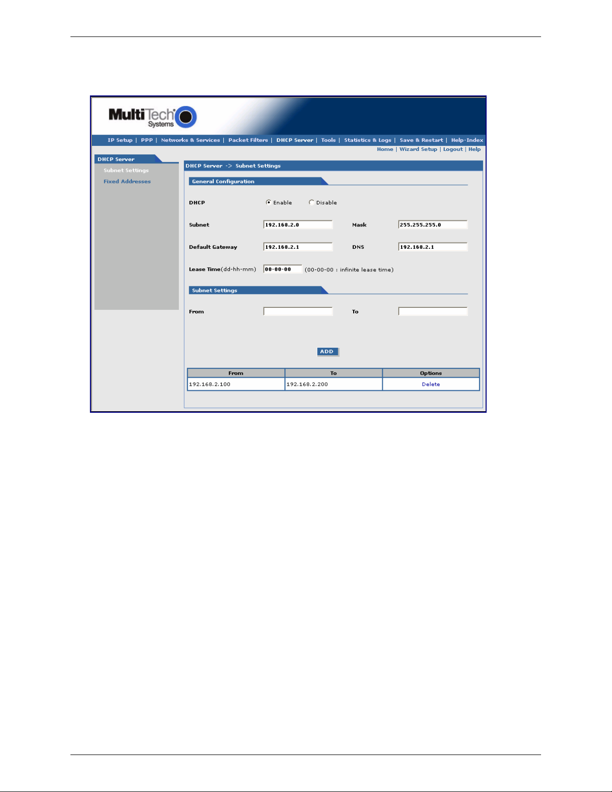
DHCP Server > Subnet Settings
Chapter 3 – Using the Web Management Software
General Configuration
DHCP (Dynamic Host Configuration Protocol) is a protocol that allows individual devices on an IP network to get
their own network configuration information (IP address, subnet mask, broadcast address, etc.) from a DHCP
server. The overall purpose of DHCP is to make it easier to administer a large network.
DHCP: Enable/disable the DHCP server.
Subnet: Enter the subnet address. For the subnet change, all the ranges have to be deleted;
otherwise, you would not be able to edit the subnet.
Mask: Enter the subnet mask address.
Gateway: Enter the gateway address.
DNS: Enter the DNS address.
Lease Time: Select the DHCP Lease Time from the selection box. Lease time is set in days, hours,
and minutes. A Lease Time of 00-00-00 is an Infinite Lease Time.
Subnet Settings
From-To Range: Enter the range of IP address for the subnet. For every range, the From and the To
addresses have to be entered in these fields.
Add: Click the Add button. The address range is added and will display in the table at the
bottom of the screen. Once the range displays, you can delete if necessary.
Multi-Tech Systems, Inc. MultiModem Wireless Modem with Ethernet Interface (S000375A) 28
Page 29

Chapter 3 – Using the Web Management Software
DHCP Server > Fixed Addresses
DHCP Fixed Configuration
The DHCP server can be made to assign a fixed IP address for a particular user by identifying the MAC address.
This binding can be made permanent by configuring it here. The same IP address will not be used for any DHCP
client with a different MAC address, even if there is no active DHCP connection with that IP address.
MAC Address: Enter the MAC address to which the specified IP address binds.
IP Address: Enter the fixed IP address to be assigned.
Add: Click the Add button. The addresses are added and will display in the table at the
bottom of the screen from where they can be deleted or changed.
Tools
Tools > Tools
DDNS
DDNS Force Update: Click the Update button to give the DDNS force update condition.
DDNS Status: Click the Refresh button to display the DDNS Status after a forced update.
Modem
Reset Modem: Click the Reset button to reset the wireless modem.
Multi-Tech Systems, Inc. MultiModem Wireless Modem with Ethernet Interface (S000375A) 29
Page 30

Chapter 3 – Using the Web Management Software
Tools > Service Status
This screen displays the status of each service that is available at run time. The first column lists the services
available at run time; the second column identifies the configuration (enabled/disabled); the third column reports the
current status of each service.
Tools > Firmware Upgrade
Firmware Upgrade
Browse File for Upgrade: Click the Browse button to open the file that allows you to locate the upgrade
file. When found, highlight the file name and press Enter so that the file name displays in the text box. Then
click the Upgrade button.
Important Notes:
• Firmware Upgrade is available only when Firmware Upgrade Configuration is enabled on the IP
Setup screen.
• The new firmware is written into the flash.
• A Firmware Upgrade will take at least 150 seconds while the firmware is downloaded. Do not cycle
power during this time.
Multi-Tech Systems, Inc. MultiModem Wireless Modem with Ethernet Interface (S000375A) 30
Page 31

Tools > Load Configuration
Load Configuration
Browse File for Load Configuration: Click the Browse button to open the file that allows you to locate the
configuration file. When found, highlight the file name and press Enter so that the file name displays in the
text box. Then click the Load button.
Important Notes:
• The new configuration is written into the flash.
• A Configuration Upgrade will take at least 3 seconds to download and 60 seconds to install the
settings and reboot. Reboot happens automatically.
Tools > Configuration Download
Chapter 3 – Using the Web Management Software
When you choose Configuration Download function, the following screen displays. It shows the name of the file you
selected on the Configuration Upgrade screen.
Click the Open, Save, Cancel, or More Info buttons as desired. The More Info button displays Microsoft’s Internet
Explorer Help on downloading files.
Multi-Tech Systems, Inc. MultiModem Wireless Modem with Ethernet Interface (S000375A) 31
Page 32

Statistics & Logs
Statistics & Logs > Ethernet
Chapter 3 – Using the Web Management Software
This is an example of the Ethernet Statistics & Logs screen. It shows the type of information you will receive
when you run this report.
Statistics & Logs > Serial
This is an example of the Serial Statistics & Logs screen. It shows the type of information you will receive when
you run this report.
Multi-Tech Systems, Inc. MultiModem Wireless Modem with Ethernet Interface (S000375A) 32
Page 33

Statistics & Logs > PPP
Chapter 3 – Using the Web Management Software
This is an example of the PPP Statistics & Logs screen. It shows the type of information you will receive when
you run this report.
Multi-Tech Systems, Inc. MultiModem Wireless Modem with Ethernet Interface (S000375A) 33
Page 34

Statistics & Logs > PPP Trace
Chapter 3 – Using the Web Management Software
This is an example of the PPP Trace Statistics & Logs screen. It shows the type of information you will receive
when you run this report.
Multi-Tech Systems, Inc. MultiModem Wireless Modem with Ethernet Interface (S000375A) 34
Page 35

Chapter 3 – Using the Web Management Software
Statistics & Logs > SysInfo
This is an example of the System Information Statistics & Logs screen. It shows the type of information you will
receive when you run this report.
Statistics & Logs > DHCP Stat
This is an example of the DHCP Statistics & Logs screen. It shows the type of information you will receive when
you run this report.
Multi-Tech Systems, Inc. MultiModem Wireless Modem with Ethernet Interface (S000375A) 35
Page 36
Chapter 4 – Wireless Antenna
Chapter 4 – Wireless Antenna
The Antenna
The antenna sub-system and integration in the application is a major issue: Choice of antenna (type, length,
performances, thermal resistance, etc.) These elements could affect GSM performances such as sensitivity and
emitted power.
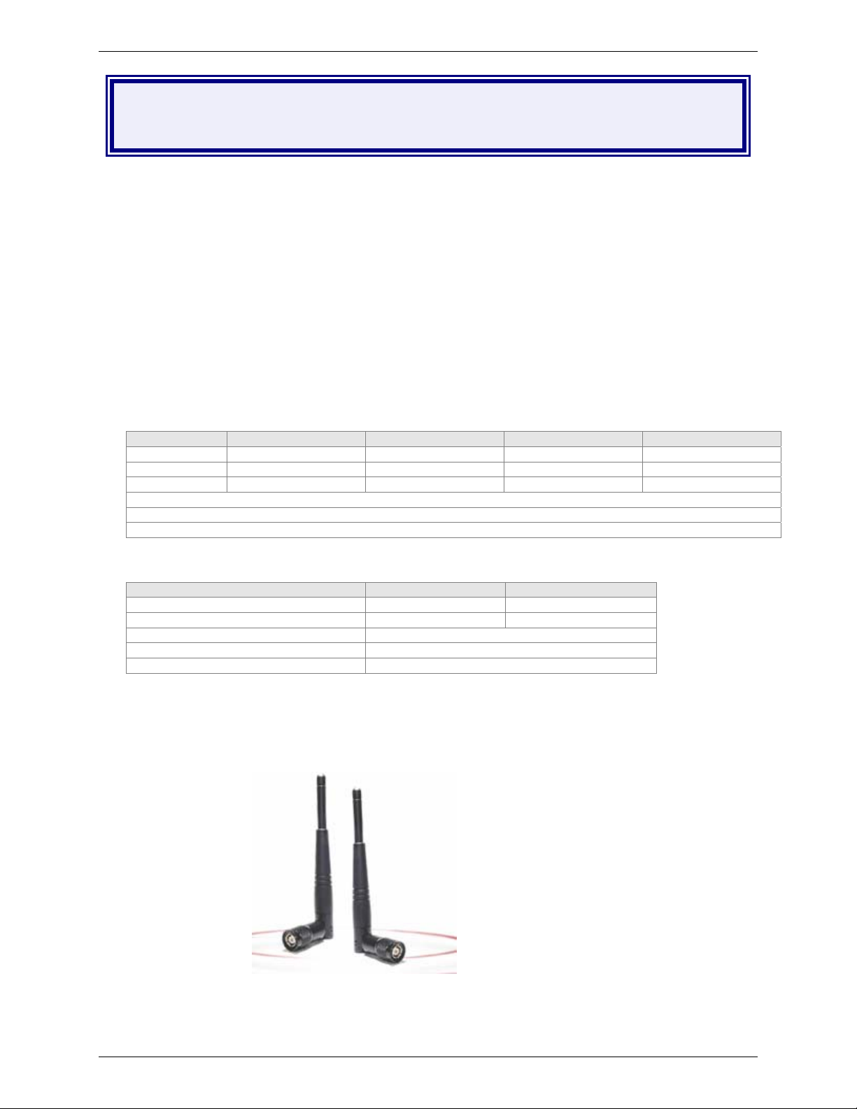
GSM and CDMA Antenna
The integrated modem antenna connector is a SMA connector. The SMA connector incorporates a 'Screw-on'
action in order to make the connection easier while providing an excellent RF performance. An additional
advantage is its small physical size, which is 50% of the standard MCX connector.
This type of connector is suitable for the standard ranges of flexible and semi-rigid cables. The characteristic
impedance of the MMCX coaxial connector is 50 ohm. The antenna manufacturer must guarantee that the
antenna will be working according to the radio characteristics presented in the table below.
GSM Radio Characteristics
Frequency RX
Frequency TX
RF Power Stand
Impedance 50 ohms
VSWR <2
Typical Radiated Gain 0 dBi on azimuth plane
CDMA Radio Characteristics
Frequency RX
Frequency TX
Impedance
VSWR
Typical Radiated Gain
Antenna
An antenna that meets the requirements for use with the SocketWireless product is included with your purchase.
GSM 850 E-GSM 900 GSM 1800 GSM 1900
869 to 894 MHz 925 to 960 MHz 1805 to 1880 MHz 1930 to 1990 MHz
824 to 849 MHz 880 to 915 MHz 1710 to 1785 MHz 1850 to 1910 MHz
2W at 12.5% duty cycle 2W at 12.5% duty cycle 1W at 12.5% duty cycle 1W at 12.5% duty cycle
CDMA 800 CDMA 1900
869 to 894 MHz 1930 to 1990 MHz
824 to 849 MHz 1850 to 1910 MHz
50 ohms
<2
0 dBi in at least one direction
Multi-Tech Systems, Inc. MultiModem Wireless Modem with Ethernet Interface (S000375A) 36
Page 37

Appendix A – Firmware Upgrade Using External TFTP Client
Appendix A – Firmware Upgrade
Using External TFTP Client
Follow the steps below to install new firmware from the Multi-Tech Systems, Inc. Web site:
Obtaining the Latest Firmware Version
To obtain the latest version of the firmware, contact you Multi-Tech Sales Representative or contact Multi-Tech
directly by phone or email:
Phone: 763-785-3500 or 800-328-9717
See the Multi-Tech Web site: www.multitech.com
1. Open the modem/router’s Web Management software using a Web Browser. Enter the Gateway Address
http://192.168.2.1 (default) and complete the login.
2. Go to the IP Setup > General Configuration screen and check the Enable button for Firmware Upgrade
under the TFTP Configuration at the button of the screen.
3. Click Save & Restart located on the Menu bar.
4. Then open the DOS screen by clicking the PC’s Start button and selecting Programs > Accessories >
Command Prompt.
5. At the C: prompt, enter the upload request by typing the following:
tftp -i <ip-address> put <firmware-filename>-tftp.bin AMD-tftp.bin
Then press Enter.
Example: tftp -i 192.168.2.1 put c:\example.bin AMD-tftp.bin (Press Enter)
Definitions of the Upload Request Parameters:
• <ip-address>
Address of the Serial-to-Ethernet Adapter to which you are uploading the firmware image.
• <firmware filename>
Filename under which the firmware file was saved on your PC or local network.
• AMD-tftp.bin <destination filename>
Filename must be AMD-tftp.bin. This is a case-sensitive file name; type it as shown here.
6. After the upgrade is completed, open the Web Management software to see if the new version shows.
Multi-Tech Systems, Inc. MultiModem Wireless Modem with Ethernet Interface (S000375A) 37
Page 38

Appendix B – Multi-Tech Systems, Inc. Warranty and Repair Policies
Appendix B – Multi-Tech Systems,
Inc. Warranty and Repair Policies
Multi-Tech Warranty Statement
Multi-Tech Systems, Inc., (hereafter “MTS”) warrants that its products will be free from defects in material or
workmanship for a period of two, five, or ten years (depending on model) from date of purchase, or if proof of
purchase is not provided, two, five, or ten years (depending on model) from date of shipment.
MTS MAKES NO OTHER WARRANTY, EXPRESS OR IMPLIED, AND ALL IMPLIED WARRANTIES OF
MERCHANTABILITY AND FITNESS FOR A PARTICULAR PURPOSE ARE HEREBY DISCLAIMED.
This warranty does not apply to any products which have been damaged by lightning storms, water, or power
surges or which have been neglected, altered, abused, used for a purpose other than the one for which they
were manufactured, repaired by Customer or any party without MTS’s written authorization, or used in any
manner inconsistent with MTS’s instructions.
MTS’s entire obligation under this warranty shall be limited (at MTS’s option) to repair or replacement of any
products which prove to be defective within the warranty period or, at MTS’s option, issuance of a refund of the
purchase price. Defective products must be returned by Customer to MTS’s factory — transportation prepaid.
MTS WILL NOT BE LIABLE FOR CONSEQUENTIAL DAMAGES, AND UNDER NO CIRCUMSTANCES WILL
ITS LIABILITY EXCEED THE PRICE FOR DEFECTIVE PRODUCTS.
Repair Procedures for U.S. and Canadian Customers
In the event that service is required, products may be shipped, freight prepaid, to our Mounds View,
Minnesota factory:
Multi-Tech Systems, Inc.
2205 Woodale Drive
Mounds View, MN 55112
Attn: Repairs, Serial # ____________
A Returned Materials Authorization (RMA) is not required. Return shipping charges (surface) will be paid by
MTS to destinations in U.S. and Canada.
Please include, inside the shipping box, a description of the problem, a return shipping address (must have
street address, not P.O. Box), your telephone number, and if the product is out of warranty, a check or
purchase order for repair charges.
For out of warranty repair charges, go to www.multitech.com/DOCUMENTS/Company/warranty/
Extended two-year overnight replacement service agreements are available for selected products. Please
call MTS customer service at (888) 288-5470 or visit our web site at
www.multitech.com/PARTNERS/Programs/orc/
Please direct your questions regarding technical matters, product configuration, verification that the product
is defective, etc., to our Technical Support department at (800) 972-2439 or email support@multitech.com
Please direct your questions regarding repair expediting, receiving, shipping, billing, etc., to our Repair
Accounting department at (800) 328-9717 or (763) 717-5631, or email mtsrepair@multitech.com.
Repairs for damages caused by lightning storms, water, power surges, incorrect installation, physical abuse,
or user-caused damages are billed on a time-plus-materials basis.
for details on rates and coverage’s.
.
Multi-Tech Systems, Inc. MultiModem Wireless Modem with Ethernet Interface (S000375A) 38
Page 39

Appendix B – Multi-Tech Systems, Inc. Warranty and Repair Policies
Repair Procedures for International Customers
(Outside U.S.A. and Canada)
Your original point of purchase Reseller may offer the quickest and most economical repair option for your
Multi-Tech product. You may also contact any Multi-Tech sales office for information about the nearest
distributor or other repair service for your Multi-Tech product. The Multi-Tech sales office directory is
available at www.multitech.com/PARTNERS/Channels/offices/
In the event that factory service is required, products may be shipped, freight prepaid to our Mounds View,
Minnesota factory. Recommended international shipment methods are via Federal Express, UPS or DHL
courier services, or by airmail parcel post; shipments made by any other method will be refused. A Returned
Materials Authorization (RMA) is required for products shipped from outside the U.S.A. and Canada. Please
contact us for return authorization and shipping instructions on any International shipments to the U.S.A.
Please include, inside the shipping box, a description of the problem, a return shipping address (must have
street address, not P.O. Box), your telephone number, and if the product is out of warranty, a check drawn
on a U.S. bank or your company’s purchase order for repair charges. Repaired units shall be shipped freight
collect, unless other arrangements are made in advance.
Please direct your questions regarding technical matters, product configuration, verification that the product
is defective, etc., to our Technical Support department nearest you or email support@multitech.com
calling the U.S., please direct your questions regarding repair expediting, receiving, shipping, billing, etc., to
our Repair Accounting department at +(763) 717-5631 in the U.S.A., or email mtsrepair@multitech.com
Repairs for damages caused by lightning storms, water, power surges, incorrect installation, physical abuse,
or user-caused damages are billed on a time-plus-materials basis.
. When
.
Repair Procedures for International Distributors
International distributors should contact their MTS International sales representative for information about
the repairs for their Multi-Tech product.
Please direct your questions regarding technical matters, product configuration, verification that the product
is defective, etc., to our International Technical Support department at +(763)717-5863. When calling the
U.S., please direct your questions regarding repair expediting, receiving, shipping, billing, etc., to our Repair
Accounting department at +(763) 717-5631 in the U.S.A. or email mtsrepair@multitech.com
Repairs for damages caused by lightning storms, water, power surges, incorrect installation, physical abuse,
or user-caused damages are billed on a time-plus-materials basis.
.
Replacement Parts
SupplyNet, Inc. can supply you with replacement power supplies, cables, and connectors for selected MultiTech products. You can place an order with SupplyNet via mail, phone, fax, or the Internet at the following
addresses:
Mail: SupplyNet, Inc.
614 Corporate Way
Valley Cottage, NY 10989
Phone: 800 826-0279
Fax: 914 267-2420
Email: info@thesupplynet.com
Internet: http://www.thesupplynet.com
Multi-Tech Systems, Inc. MultiModem Wireless Modem with Ethernet Interface (S000375A) 39
Page 40

Appendix C – Waste Electrical and Electronic Equipment
Appendix C – Waste Electrical and
Electronic Equipment
July, 2005
Waste Electrical and Electronic Equipment (WEEE)
The WEEE directive places an obligation on EU-based manufacturers, distributors, retailers and importers to takeback electronics products at the end of their useful life. A sister Directive, ROHS (Restriction of Hazardous
Substances) complements the WEEE Directive by banning the presence of specific hazardous substances in the
products at the design phase. The WEEE Directive covers all Multi-Tech products imported into the EU as of August
13, 2005. EU-based manufacturers, distributors, retailers and importers are obliged to finance the costs of recovery
from municipal collection points, reuse, and recycling of specified percentages per the WEEE requirements.
Instructions for Disposal of WEEE by Users in the European Union
The symbol shown below is on the product or on its packaging, which indicates that this product must not be
disposed of with other waste. Instead, it is the user’s responsibility to dispose of their waste equipment by handing it
over to a designated collection point for the recycling of waste electrical and electronic equipment. The separate
collection and recycling of your waste equipment at the time of disposal will help to conserve natural resources and
ensure that it is recycled in a manner that protects human health and the environment. For more information about
where you can drop off your waste equipment for recycling, please contact your local city office, your household
waste disposal service or where you purchased the product.
Multi-Tech Systems, Inc. MultiModem Wireless Modem with Ethernet Interface (S000375A) 40
Page 41

Index
Index
A
always-on network connection ...................................5
Application Example...................................................6
Auto Dialout configuration ........................................16
Autodiscovery configuration .....................................16
B
Broadcast timer ........................................................16
Browse File for Load Configuration ..........................31
Browse File for Upgrade ..........................................30
C
Caller ID for Wakeup on Call....................................22
CDMA technology ......................................................5
Check IP Server.......................................................17
Configuration Download...........................................31
Configuration Upgrade .............................................31
Configure Ethernet functionality .................................9
D
Date and time...........................................................12
Daylight Savings Time configuration........................18
DDNS authentication................................................17
DDNS Client.............................................................17
DDNS configuration .................................................17
DDNS force update ..................................................29
DDNS Status............................................................29
DHCP configuration .................................................28
DHCP fixed addresses.............................................29
DHCP server............................................................28
DHCP subnet setting................................................28
dial-on-demand ..........................................................5
Dial-on-Demand.......................................................21
DNAT configuration..................................................26
E
EDGE technology.......................................................5
Ethernet LEDs..........................................................12
Ethernet ports caution ................................................6
F
Firmware Upgrade ...................................................30
Front panels .............................................................12
G
General Configuration ..............................................15
GPRS technology.......................................................5
GSM/GPRS and CDMA Antenna.............................36
H
H323 packets ...........................................................27
Handling Precautions .................................................6
HTTP authentication ................................................16
HTTP configuration ..................................................16
I
ICMP configuration...................................................27
ICMP Keep Alive Check...........................................22
Multi-Tech Systems, Inc. MultiModem Wireless Modem with Ethernet Interface (S000375A) 41
Idle time out .............................................................21
IP Configuration .......................................................16
IP Server ..................................................................17
ITCP.........................................................................25
L
LEDs ........................................................................12
M
Menu structure .........................................................11
Modem authentication..............................................22
Modem LEDs ...........................................................12
N
Navigating ................................................................11
Network configuration ..............................................23
Network/Host for Remote Configuration...................20
O
Obtain DNS Server Address Automatically ................8
Obtain IP Address automatically ................................8
Ordering Replacement Parts....................................39
P
Packet Filter .............................................................25
Packet filter rules......................................................25
Polling time ..............................................................18
Power and Ethernet connections ...............................8
PPP authentication...................................................21
PPP configuration ....................................................21
PPTP packet passthrough .......................................27
protocol ....................................................................25
R
Radio Characteristics ...............................................36
Raw Dialout configuration ........................................16
Remote Configuration ..............................................20
Repair ......................................................................38
Replacement Parts...................................................39
Reset button...............................................................8
Reset for 5 seconds ...................................................8
Reset Modem Tools .................................................29
Route configuration ..................................................19
S
Safe password .........................................................16
Safety Warnings.........................................................6
Save & Restart.........................................................10
Screen buttons.........................................................11
Server Port...............................................................16
Service Configuration...............................................24
Service Status in Tools ............................................30
Setup Wizard........................................................9, 10
Ship Kit Contents .......................................................6
Shutdown caution.....................................................12
SNTP configuration ..................................................18
Specifications .............................................................7
Static Routes configuration ......................................19
Statistics & Logs > DHCP Statistics .........................35
Page 42

Statistics & Logs > Ethernet .....................................32
Statistics & Logs > PPP ...........................................33
Statistics & Logs > PPP Trace .................................34
Statistics & Logs > Serial .........................................32
Statistics & Logs > SysInfo.......................................35
Sub-menus...............................................................11
Syslog configuration.................................................16
System domain name ..............................................17
T
TCP/IP address..........................................................8
Test your workstation ...............................................12
TFTP configuration...................................................16
Index
Time zone configuration...........................................18
Tools ........................................................................29
U
UDP .........................................................................25
W
Wakeup on Call........................................................22
Warranty ..................................................................38
Web Management software .......................................9
Wireless activation .....................................................8
Wireless Service Provider ..........................................8
Multi-Tech Systems, Inc. MultiModem Wireless Modem with Ethernet Interface (S000375A) 42
 Loading...