

Page 1
SocketModem® Cell EV-DO
SocketModem® iCell EV-DO
MTSMC-EV3 Device Guide
COPYRIGHT AND TECHNICAL SUPPORT
Multi-Tech Systems, Inc. Device Guide 1
Page 2

COPYRIGHT AND TECHNICAL SUPPORT
SocketModem EV-DO MTSMC-EV3 Device Guide
2
Contacting Multi-Tech
Knowledge Base
The Knowledge Base provides immediate access to support information and resolutions for all Multi-Tech products. Visit
http://www.multitech.com/kb.go.
Support Portal
To create an account and submit a support case directly to our technical support team, visit: https://support.multitech.com
Technical Support
Business Hours: M-F, 9am to 5pm CT
Country
By Email
By Phone
Europe, Middle East, Africa:
support@multitech.co.uk
+(44) 118 959 7774
U.S., Canada, all others:
support@multitech.com
(800) 972-2439 or (763) 717-5863
World Headquarters
Multi-Tech Systems, Inc.
2205 Woodale Drive
Mounds View, Minnesota 55112
Phone: 763-785-3500 or 800-328-9717
Fax: 763-785-9874
Warranty
To read the warranty statement for your product, please visit: http://www.multitech.com/warranty.go.
SocketModem SocketModem Cell EV-DO and SocketModem iCell EV-DO
MTSMC-EV3 Device Guide
S000541, Version F
MTSMC-EV3-xx, MTSMC-EV3-MI-GP-xx, MTSMC-EV3-MI-IP-xx, MTSMC-EV3-GP-xx, MTSMC-EV3-IP-xx, MTSMC-EV3-U-xx
Copyright
This publication may not be reproduced, in whole or in part, without prior expressed written permission from Multi-Tech Systems, Inc. All rights reserved.
Copyright © 2014 by Multi-Tech Systems, Inc.
Multi-Tech Systems, Inc. makes no representations or warranties with respect to the contents hereof and specifically disclaim any implied warranties of
merchantability or fitness for any particular purpose. Furthermore, Multi-Tech Systems, Inc. reserves the right to revise this publication and to make
changes from time to time in the content hereof without obligation of Multi-Tech Systems, Inc. to notify any person or organization of such revisions or
changes.
Trademarks
SocketModem, SocketWireless, Universal IP, SocketEthernet IP and the Multi-Tech logo are registered trademarks of Multi-Tech Systems, Inc. All
other brand and product names are trademarks or registered trademarks of their respective companies.
Page 3

CONTENTS
3
SocketModem EV-DO MTSMC-EV3 Device Guide
Contents
Chapter 1 – Device Overview ......................................................................................................................................5
Description .......................................................................................................................................................................... 5
Product Build Options ......................................................................................................................................................... 5
Documentation ................................................................................................................................................................... 6
Chapter 2 – Mechanical Drawing ................................................................................................................................7
MTSMC-EV3 Builds .............................................................................................................................................................. 7
Chapter 3 – Specifications ..........................................................................................................................................8
Technical Specifications ...................................................................................................................................................... 8
Mounting Hardware ............................................................................................................................................................ 9
Recommended Parts ....................................................................................................................................................... 9
Device Reset ........................................................................................................................................................................ 9
RS-232 Signal DC Electrical Characteristics ....................................................................................................................... 10
Absolute Maximum Rating ........................................................................................................................................... 10
Electrical Characteristics Other Pins ................................................................................................................................. 10
Pinout Specifications ......................................................................................................................................................... 11
Pin 58 ................................................................................................................................................................................. 11
Pin Availability by Build ..................................................................................................................................................... 12
Power Measurements ....................................................................................................................................................... 13
MTSMC-EV3 .................................................................................................................................................................. 13
MTSMC-EV3-U .............................................................................................................................................................. 14
MTSMC-EV3-MI-IP ........................................................................................................................................................ 15
MTSMC-EV3-MI-GP ....................................................................................................................................................... 16
Chapter 4 – FCC and Industry Canada Information .................................................................................................... 18
FCC Grant Part 22 and 24 .................................................................................................................................................. 18
Industry Canada ................................................................................................................................................................ 19
Chapter 5 – Carrier Specific Information ................................................................................................................... 20
Notice for Devices that Use Aeris Radios .......................................................................................................................... 20
Chapter 6 – Application Notes .................................................................................................................................. 21
LED Interface ..................................................................................................................................................................... 21
LED 1 – Heartbeat – IP and –GP Builds Only ................................................................................................................. 21
LED 2 – Link Status – All Builds ...................................................................................................................................... 21
LED 3 – Signal Strength –IP and –GP Builds Only .......................................................................................................... 21
LED 4 – GPS Status – GP Builds ..................................................................................................................................... 21
Page 4

CONTENTS
SocketModem EV-DO MTSMC-EV3 Device Guide
4
RF Performances ............................................................................................................................................................... 22
Receiver Features.......................................................................................................................................................... 22
Transmitter Features .................................................................................................................................................... 22
RF Connection and Antenna ......................................................................................................................................... 22
Frequency Bands ............................................................................................................................................................... 23
Page 5

CHAPTER 1 –DEVICE OVERVIEW
5
SocketModem EV-DO MTSMC-EV3 Device Guide
Product
Description
Region
MTSMC-EV3-MI-GP-N3
EV-DO Rev A, Serial, USB, GPIO, Universal IP, GPS, Verizon
USA
MTSMC-EV3-MI-GP-N16
EV-DO Rev A, Serial, USB, GPIO, Universal IP, GPS, Aeris
USA
MTSMC-EV3-MI-IP-N3
EV-DO Rev A, Serial, USB, GPIO, Universal IP, Verizon
USA
MTSMC-EV3-MI-IP-N16
EV-DO Rev A, Serial, USB, GPIO, Universal IP, Aeris
USA
MTSMC-EV3-GP-N3
EV-DO Rev A, Serial, Universal IP, GPS, Verizon
USA
MTSMC-EV3-GP-N16
EV-DO Rev A, Serial, Universal IP, GPS, Aeris
USA
MTSMC-EV3-IP-N3
EV-DO Rev A, Serial, Universal IP, Verizon
USA
MTSMC-EV3-IP-N16
EV-DO Rev A, Serial, Universal IP, Aeris
USA
MTSMC-EV3-N3
EV-DO Rev A, Serial, Verizon
USA
MTSMC-EV3-N16
EV-DO Rev A, Serial, Aeris
USA
MTSMC-EV3-U-N3
EV-DO Rev A, USB, Verizon
USA
MTSMC-EV3-U-N16
EV-DO Rev A, USB, Aeris
USA
Developer Kit
MTSMI-UDK
Universal Developer Kit
Global
Chapter 1 – Device Overview
Description
The SocketModem iCell intelligent cellular modem is a complete, ready-to-integrate communications device that
offers standards-based dual-band EV-DO Rev A performance. This quick-to-market communications device allows
developers to add wireless communication and GPS tracking to products with a minimum of development time
and expense. The intelligence of the embedded Universal IP® stack allows for automatic/persistent connectivity
for mission critical applications and enhanced M2M functionality. The SocketModem iCell intelligent cellular
modem is based on industry-standard open interfaces and uses Multi-Tech's Universal Socket design.
Product Build Options
Notes:
These units ship without network activation. To connect them to the cellular network, you need a cellular
account. Refer to Multi-Tech’s Cellular Activation site http://www.multitech.com/activation.go for step-by-
step instructions on activating your cellular modem.
GP devices have a dedicated GPS receiver.
MI devices have multiple interfaces.
The complete product code may end in .Rx. For example, MTSMC-EV3.Rx, where R is revision and x is the
revision number.
All builds can be ordered individually or in 50-packs.
Page 6

CHAPTER 1 – DEVICE OVERVIEW
SocketModem EV-DO MTSMC-EV3 Device Guide
6
Documentation
The following documentation is available by email to oemsales@multitech.com or by using the Developer Guide
Request Form on the multitech.com
Device Guides – This document. Provides model-specific specifications and developer information.
Universal Socket Developer Guide – Provides an overview, safety and regulatory information, design
considerations, schematics, and general device information. (S000342)
USB Driver Installation Guide – Provides steps for installing EV-DO/CDMA USB drivers. (S000569)
AT Command Guide – Use the following AT Command Guides with EV-DO devices:
S000546 for EV-DO and CDMA Modems
S000457 Universal IP Commands
Page 7
CHAPTER 1 –DEVICE OVERVIEW
7
SocketModem EV-DO MTSMC-EV3 Device Guide
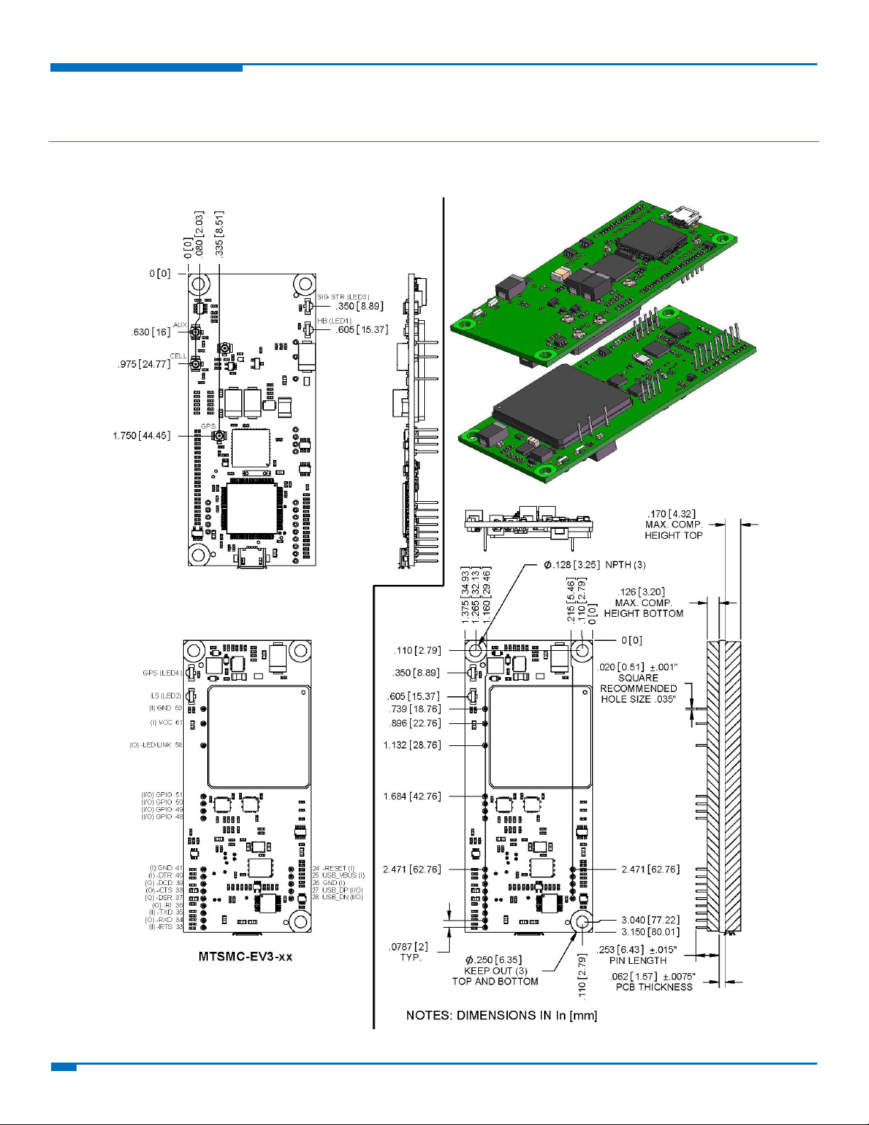
Chapter 2 – Mechanical Drawing
MTSMC-EV3 Builds
Page 8

CHAPTER 3 – SPECIFICATIONS
SocketModem EV-DO MTSMC-EV3 Device Guide
8
Category
Description
General
Standards
CDMA2000 1xRTT
EV-DO Rev. A (backward compatible to EV-DO Rev. 0 and CDMA 1x networks)
SMS is based on CS/Packet-Switched (PS) domain of GSM and WCDMA
Frequency Bands
Dual-band 800/1900 MHz bands with receive diversity support on both bands
Speed
Data Speed
Up to 3.1 Mbps downlink/1.8 Mbps uplink
Interface, Ports
USB Interface
MI builds: USB 2.0 full speed
High speed on other builds: 480 Mbps
Serial Modem Interface
Up to 921.6 Kbps
Ports
GPIO ports – MI builds only
Physical Description
Weight
1 oz. (28g)
Dimensions
3.15" x 1.375" (80.010 mm x 34.925 mm)
Connectors
Antenna Connector
3 surface mount UFL: cellular, GPS, RX diversity
Environment
Operating Temperature
-40° C to +85° C
Storage Temperature
-40° C to +85° C
Humidity
20%-90% RH, non-condensing
Power Requirements
Operating Voltage
3.3V-5V
Input Power
5 or 3.3 VDC
IP, M2M, SMS
Supported IP Protocols
DNS resolve, FTP client, Ping, POP3 client, PPP (dialout), SMTP client, TCP RAW client &
server
M2M Applications
iCell models: Automatic connect/reconnect, device monitor, modem emulation, Ping &
TCP keep alive, wake-up on caller ID, wake-up on ring, GPS tracking (GP model only)
SMS
Point-to-Point messaging
Mobile-Terminated SMS
Mobile-Originated SMS
Chapter 3 – Specifications
Technical Specifications
Page 9

CHAPTER 3 – SPECIFICATIONS
9
SocketModem EV-DO MTSMC-EV3 Device Guide
Category
Description
Certifications, Compliance
EMC Compliance
FCC Part 15 Class B
EN55022 Class B
EN55024
Radio Compliance
FCC Part 22
FCC Part 24
RSS 132
RSS 133
EN 301 511
EN 301 489-1
EN 301 489-7
EN 301 489-24
Safety Compliance
UL 60950-1
cUL 60950-1
EN 60590-1
Network Compliance
Verizon, Aeris
Manufacturer
Part
Part Number
PEM PennEngineering
Surface Mount Standoff
SMTSO-M3-4ET
RAF Electronic Hardware
3/16” Hex Female Standoff
2051T-440-S-12 Zinc
RAF Electronic Hardware
4.5mm Hex Female Standoff
1251-3005-S-12 Zinc
Model
"X" Time
Minimum Reset Pulse1
MTSMC-EV3
10 seconds
200 us
Notes: Radio performance may be affected by temperature extremes. This is normal.
Mounting Hardware
The board has three mounting holes at corners. Use #4 or M3 hardware for mounting the SocketModem to the
board. Refer to the Mechanical Drawings for more information.
Recommended Parts
Device Reset
The SocketModem is ready to accept commands after a fixed amount of time (“X” Time) after power-on or reset.
1
The SocketModem may respond to a shorter reset pulse.
Page 10

CHAPTER 3 – SPECIFICATIONS
SocketModem EV-DO MTSMC-EV3 Device Guide
10
Pin
Signal Name
Pin
Signal Name
J33
-RTS
J37
-DSR
J34
-RXD
J38
-CTS
J35
-TXD
J39
-DCD
J36
-RI
J40
-DTR
Parameter
Minimum
Maximum
3.3 Volt Powered
Input Low Level
0
0.55
Input High Level
1.5
3.3
Output Low Level
0
0.55
Output High Level
2.35
3.3
5 Volt Powered
Input Low Level
0
0.8
Input High Level
2.3 5 Output Low Level
0
0.55
Output High Level
3.7
5
Pin
Signal Name
VIL
VIH VOL
VOH
Min
Max
Min
Max
Min
Max
Min
Max
J24
-RESET
0.8
2.0 --
--
--
--
J25
USB VBUS
-0.3
0.8
2.0
8.7
--
--
--
--
J26
GND
--
--
--
--
--
--
--
--
J27
USB DP
0.8 2 0.3
2.8 J28
USB DM
0.8 2 0.3
2.8 J41
GND
--
--
--
--
--
--
--
--
J48
GPIO0
-0.3
0.8
2.0
5.5 0.4
2.9
J49
GPIO1
-0.3
0.8
2.0
5.5 0.4
2.9 J50
GPIO2
-0.3
0.8
2.0
5.5 0.4
2.9
J51
GPIO3
-0.3
0.8
2.0
5.5 0.4
2.9
J58
-LED LINK
--
--
--
-- 0 0.45
2.85
3.3
J61
VCC
--
--
--
--
--
--
--
--
J63
GND
--
--
--
--
--
--
--
--
RS-232 Signal DC Electrical Characteristics
Units: Volts
Applies to the following pins:
Absolute Maximum Rating
All models can run with an input voltage of either 3.3V or 5V. The maximum voltage on any signal pin equals the
input voltage.
Electrical Characteristics Other Pins
Page 11

CHAPTER 3 – SPECIFICATIONS
11
SocketModem EV-DO MTSMC-EV3 Device Guide
Pin
Signal Name
Logic Level Voltage1
I/O
Description
J24
–RESET
3.3 – 5.0
I
Device reset (active low)
J25
USB VBUS
3.3 – 5.0
I
USB power supply input
J26
GND
GND
GND
Ground
J27
USB DP
3.3
I/O
USB data
J28
USB DN
3.3
I/O
USB data
J33
–RTS
5.0 I Request to send (active low)
J34
–RXD
5.0 O Received data (active low)
J35
–TXD
5.0 I Transmitted data (active low)
J36
–RI
5.0 O Ring indicator (active low)
J37
–DSR
5.0 O Data set ready (active low)
J38
–CTS
5.0 O Clear to send (active low)
J39
–DCD
5.0 O Data carrier detect (active low)
J40
–DTR
5.0 I Data terminal ready (active low)
J41
GND
GND
GND
Ground
J48
GPIO0
3.3
I/O
User configurable general purpose I/O
J49
GPIO1
3.3
I/O
User configurable general purpose I/O
J50
GPIO2
3.3
I/O
User configurable general purpose I/O
J51
GPIO3
3.3
I/O
User configurable general purpose I/O
J58
–LED LINK
3.3 O Link status (active low, can sink up to 150mA)
J61
VCC
5.0
PWR
DC input power
J63
GND
GND
GND
Ground
Pin 58 LED Mode
Operating Status
OFF
Subscriber Carrier Mode is OFF or running in SLEEP or ALARM mode.
600 ms ON/600ms OFF
No PIN entered, network search in progress, ongoing user authentication, or network
login in progress.
75 ms ON / 75 ms OFF /
75 ms ON
3 s OFF
Flashing or Blinking
One or more EDGE/GPRS/CDMA contexts activated. Indicates EDGE/GPRS/CDMA data
transfer: When a transfer is in progress, the LED goes on within 1 second after data
packets were exchanged.
Flash duration is approximately 0.5 s.
ON
Depending on call type:
Voice Call:
Connected to remote party.
Data Call:
Connected to remote party or parameter exchange while call is set up or
disconnected.
Pinout Specifications
1
A hyphen (-) indicates a range of acceptable logic levels.
Pin 58
Note: Pin 58 may or may not be available on some SocketModems.
Page 12

CHAPTER 3 – SPECIFICATIONS
SocketModem EV-DO MTSMC-EV3 Device Guide
12
Pin and Function
MI-IP/GP
IP/GP
Serial only
USB only
J24 Reset
x x x
x
J25 USB_VBUS
x x J26 GND
x x x x J27 USB_DP
x x J28 USB_DN
x x J33 -RTS
x x x J34 -RXD
x x x J35 -TXD
x x x J36 -RI
x x x
J37 -DSR
x x x
J38 -CTS
x x x J39 -DCD
x x x J40 -DTR
x x x
J41 GND
x x x
x
J48 GPIO
x J49 GPIO
x J50 GPIO
x J51 GPIO
x J58 -LED LINK
x x J61 VCC
x x x x J63 GND
x x x
x
Pin Availability by Build
Page 13

CHAPTER 3 – SPECIFICATIONS
13
SocketModem EV-DO MTSMC-EV3 Device Guide
Radio Protocol
AT command used to
set radio function
and power mode
Sleep mode current
(Amps)
Time (sec) to reduce
power from command
or DTE signal change
Time (sec) to “ready
for data
connection” from
reduced power
3.3 Volts
US Cellular
AT+CFUN=5
0.046
1.0
1.0
PCS
AT+CFUN=5
N/A
N/A
N/A
EV-DO
AT+CFUN=5
0.023
1.0
1.0
5 Volts
US Cellular
AT+CFUN=5
0.049
1.0
1.0
PCS
AT+CFUN=5
N/A
N/A
N/A
EV-DO
AT+CFUN=5
0.022
1.0
1.0
Radio
Protocol
AT
command
used to set
radio
function and
power mode
Connection
No Data
(Amps)
Half Power
Max Power
Average
Measured
Current
(Amps)
Output
Power
Level
Ch Power
Meas.
(Avg)
Average
Measured
Current
(Amps)
Output
Power
Level
Ch Power
Meas.
(Avg)
3.3 Volts
US Cellular
AT+CFUN=1
0.062
0.205
-13
-60
0.855
22
-97
PCS
AT+CFUN=1
N/A
0.189
-16
-60
0.956
20
-99
EV-DO
AT+CFUN=1
0.049
0.205
-25
-70
0.664
21
-96
5 Volts
US Cellular
AT+CFUN=1
0.053
0.143
-13
-60
0.53
21
-60
PCS
AT+CFUN=1
N/A
0.134
-16
-60
0.617
21
-60
EV-DO
AT+CFUN=1
0.034
0.141
-25
-70
0.423
21
-70
Power Measurements
Multi-Tech Systems, Inc. recommends that you incorporate a 10% buffer into your power source when
determining product load.
MTSMC-EV3
Note: This data is measured using an Agilent call box connected to the cellular radio.
Page 14

CHAPTER 3 – SPECIFICATIONS
SocketModem EV-DO MTSMC-EV3 Device Guide
14
Radio
Protocol
Instant Peak TX
Current (Amps)
Total Inrush Charge
measured in Coulombs
Inrush Duration (Total Inrush Charge
duration during powerup).
3.3 Volts
US Cellular
0.956
17.70mC
1.90ms
PCS
1.084
17.70mC
1.90ms
EV-DO
0.744
17.70mC
1.90ms
5 Volts
US Cellular
0.608
17.77mC
1.74ms
PCS
0.696
17.77mC
1.74ms
EV-DO
0.496
17.77mC
1.74ms
Radio
Protocol
AT
command
used to set
radio
function and
power mode
Connection
No Data
(Amps)
Half Power
Max Power
Average
Measured
Current
(Amps)
Output
Power
Level
Ch Power
Meas.
(Avg)
Average
Measured
Current
(Amps)
Output
Power
Level
Ch Power
Meas.
(Avg)
3.3 Volts
US Cellular
AT+CFUN=1
0.062
0.220
-13
-60
0.845
22.7
-96.2
PCS
AT+CFUN=1
N/A
0.201
-16
-60
0.878
21
-99.1
EV-DO
AT+CFUN=1
0.057
0.218
-26
-70
0.690
23
-96
5 Volts
US Cellular
AT+CFUN=1
0.056
0.146
-13
-60
0.521
22
-60
PCS
AT+CFUN=1
N/A
0.133
-16
-60
0.541
22
-99
EV-DO
AT+CFUN=1
0.043
0.145
-25
-70
0.436
22
-96
Notes:
AT+CFUN=1 used to set radio function and power mode.
Instant Peak Tx: The peak current during a transmission burst period or connection. This current is handled by
bulk capacitance in a design.
Measured Current: The continuous current during a Transmit with the radio transmitter at specified power.
Inrush Charge: The total inrush charge current amplitude at power on.
MTSMC-EV3-U
Note: This data is measured using an Agilent call box connected to the cellular radio.
Page 15

CHAPTER 3 – SPECIFICATIONS
15
SocketModem EV-DO MTSMC-EV3 Device Guide
Radio
Protocol
Instant Peak TX
Current (Amps)
Total Inrush Charge
measured in Coulombs
Inrush Duration (Total
Inrush charge duration
during powerup).
3.3 Volts
US Cellular
0.920
18.23mC
1.91ms
PCS
0.936
18.23mC
1.91ms
EV-DO
0.768
18.23mC
1.91ms
5 Volts
US Cellular
0.604
17.90mC
1.82ms
PCS
0.624
17.90mC
1.82ms
EV-DO
0.508
17.90mC
1.82ms
Radio
Protocol
AT command
used to set
radio function
and power mode
Connection
No Data
(Amps)
Half Power
Max Power
Average Measured
Current (Amps)
Average Measured
Current (Amps)
3.3 Volts
US Cellular
AT+CFUN=1
0.140
0.302
0.890
PCS
AT+CFUN=1
N/A
0.285
1.041
EV-DO
AT+CFUN=1
0.124
0.304
0.818
5 Volts
US Cellular
AT+CFUN=1
0.090
0.190
0.580
PCS
AT+CFUN=1
N/A
0.180
0.616
EV-DO
AT+CFUN=1
0.083
0.187
0.485
Notes:
AT+CFUN=1 used to set radio function and power mode.
Instant Peak Tx: The peak current during a transmission burst period or connection. This current is handled by
bulk capacitance in a design.
Measured Current: The continuous current during a Transmit with the radio transmitter at specified power.
Inrush Charge: The total inrush charge current amplitude at power on.
MTSMC-EV3-MI-IP
Note: This data is measured using an Agilent call box connected to the cellular radio.
Page 16

CHAPTER 3 – SPECIFICATIONS
SocketModem EV-DO MTSMC-EV3 Device Guide
16
Radio
Protocol
Instant Peak TX
Current (Amps)
Total Inrush Charge
measured in Coulombs
Inrush Duration (Total
Inrush charge duration
during powerup).
3.3 Volts
US Cellular
1.056
15.37mC
1.84ms
PCS
1.276
15.37mC
1.84ms
EV-DO
1.12
15.37mC
1.84ms
5 Volts
US Cellular
0.664
15.37mC
1.84ms
PCS
0.752
15.37mC
1.84ms
EV-DO
0.644
15.37mC
1.84ms
Radio
Protocol
AT
command
used to set
radio
function and
power mode
Connection
No Data
(Amps)
Half Power
Max Power
Average
Measured
Current
(Amps)
Output
Power
Level
Ch Power
Meas.
(Avg)
Average
Measured
Current
(Amps)
Output
Power
Level
Ch Power
Meas.
(Avg)
3.3 Volts
US Cellular
AT+CFUN=1
0.270
0.412
-13
-60
1.000
22
-97
PCS
AT+CFUN=1
N/A
0.395
-16
-60
1.151
20
-99
EV-DO
AT+CFUN=1
0.240
0.414
-25
-70
0.928
21
-96
5 Volts
US Cellular
AT+CFUN=1
0.173
0.270
-13
-60
0.660
22
-95
PCS
AT+CFUN=1
N/A
0.260
-16
-60
0.696
21
-60
EV-DO
AT+CFUN=1
0.161
0.267
-25
-70
0.565
23
-70
Notes:
AT+CFUN=1 used to set radio function and power mode.
Instant Peak Tx: The peak current during a transmission burst period or connection. This current is handled by
bulk capacitance in a design.
Measured Current: The continuous current during a Transmit with the radio transmitter at specified power.
Inrush Charge: The total inrush charge current amplitude at power on.
MTSMC-EV3-MI-GP
Note: This data is measured using an Agilent call box connected to the cellular radio.
Page 17

CHAPTER 3 – SPECIFICATIONS
17
SocketModem EV-DO MTSMC-EV3 Device Guide
Radio
Protocol
Instant Peak TX
Current (Amps)
Total Inrush Charge
measured in Coulombs
Inrush Duration (Total
Inrush charge duration
during powerup).
3.3 Volts
US Cellular
1.056
15.37mC
1.84ms
PCS
1.276
15.37mC
1.84ms
EV-DO
1.12
15.37mC
1.84ms
5 Volts
US Cellular
0.664
15.74mC
1.75ms
PCS
0.752
15.74mC
1.75ms
EV-DO
0.644
15.74mC
1.75ms
Notes:
AT+CFUN=1 used to set radio function and power mode.
Instant Peak Tx: The peak current during a transmission burst period or connection. This current is handled by
bulk capacitance in a design.
Measured Current: The continuous current during a Transmit with the radio transmitter at specified power.
Inrush Charge: The total inrush charge current amplitude at power on.
Page 18

CHAPTER 4 – FCC AND INDUSTRY CANADA INFORMATION
SocketModem EV-DO MTSMC-EV3 Device Guide
18
FCC Identifier
RI7DE910-DUAL
Equipment Class
PCS Licensed Transmitter
Notes
Dual Band CDMA/GPS module
FCC Rule Parts
22H, 24E
Approval
Single Modular
FCC Rule Parts
Frequency Range (MHz)
Output Watts
Frequency Tolerance
Emission Designators
22H
824.7 - 848.31
0.3
2.5 PM
1M29F9W
24E
1851.25-1908.75
0.274
2.5 PM
1M29F9W
Chapter 4 – FCC and Industry Canada Information
The following is device specific FCC information. For additional approval and regulatory information, see the Universal
Socket Developer Guide.
FCC Grant Part 22 and 24
Power listed is conducted. The maximum antenna gain including cable loss for compliance with radiated power
limits, RF exposure requirements and the categorical exclusion requirements of 2.1091 is 5.12 dBi for part 22H and
6.12 dBi for part 24E. The antenna(s) used for this transmitter must be installed to provide a separation distance
of at least 20 cm from all persons and must not transmit simultaneously with any other antenna or transmitter.
This device is allowed only for OEM integration into host products. Consumer or end-user installation is not
allowed. End-users and OEM integrators must be provided with specific information required to satisfy RF
exposure compliance.
Page 19

CHAPTER 4 – FCC AND INDUSTRY CANADA INFORMATION
19
SocketModem EV-DO MTSMC-EV3 Device Guide
Certification Number/No. de Certification
5131A-DE910Dual
Certificate Number/Numéro de Certificat
1-03726
Type of Radio Equipment/Genre de Matériel
Cellular Mobile New Technologies (824-849MHz)
Model/Modele
DE910-DUAL
From Frequency/
De Fréquences
To Frequency/
Á Fréquences
Emission Designation/Genre
d’émission
Power/Puisaance
(Watts)
827.7
848.31
1M28F9W
0.298
1851.25
1908.75
1M29F9W
0.274
Industry Canada
Certification of equipment means only that the equipment has met the requirements of the above noted
specification. License applications, where applicable to use certified equipment, are acted on accordingly by the
Industry Canada issuing office and will depend on the existing radio environment, service and location of
operation. This certificate is issued on condition that the holder complies and will continue to comply with the
requirements and procedures issued by Industry Canada. The equipment for which this certificate is issued shall
not be manufactured, imported distributed, leased, offered for sale or sold unless the equipment complies with
the applicable technical specifications and procedures issued by Industry Canada.
La certification du matériel signifie seulement que le matériel a satisfait aux exigences de la norme indiquée ci-
dessus. Les demandes de licences nécessaires pour l’utilisation du matériel certifié sont traitées en conséquence
par le bureau de délivrance d’Industrie Canada et dépendent des conditions radio ambiantes, du service et de
l’emplacement d’exploitation. Le présent certificat est délivré à la condition que le titulaire satisfasse et continue
de satisfaire aux exigences et aux procédures d’Industrie Canada. Le matériel à l’égard duquel le présent certificat
est délivré ne doit pas être fabriqué, importé, distribué, loué, mis en vente ou vendu à moins d’être conforme aux
procédures et aux spécifications techniques applicable publiées par Industrie Canada.
Page 20

CHAPTER 5 – CARRIER SPECIFIC INFORMATION
SocketModem EV-DO MTSMC-EV3 Device Guide
20
Chapter 5 – Carrier Specific Information
Notice for Devices that Use Aeris Radios
One component of your device is a radio. A radio algorithm prevents your device from repeatedly attempting to
connect to the network when the radio:
cannot establish a packet data connection or
fails to access the application server.
When writing applications for your devices, ensure that your applications do not interfere with the radio's
connection retry algorithm. If you fail to do so, Aeris might block network access for your devices.
After your devices reach the end of their commercial lifespan, you must remove them from the Aeris network. To
do so, remove power from the devices and remove their antennas. If your devices continue to attempt to register
with the network after you cancel device subscriptions, Aeris can bill you for any traffic generated by those
devices.
Page 21

CHAPTER 6 – APPLICATION NOTES
21
SocketModem EV-DO MTSMC-EV3 Device Guide
LED 1 Signal
Heartbeat LED
OFF
No power to the unit.
Blinking
Power on.
LED 2 Signal
Link Status LED
OFF
Device off.
ON
Continuously lit
During initial connection to tower or when connected and
passing data.
Slow blink (-0.2Hz)
Registered to tower and idle.
Faster blink (-3Hz)
Powered not registered/Searching for registration.
LED 1 Signal
Heartbeat LED
OFF
No signal
Blinking
The faster the LED blinks, the stronger the signal. The blink rate range is -0.5Hz to -10Hz.
LED 4 Signal
GPS Status LED
OFF
No power to the unit.
ON
Continuously lit
Satellite not acquired.
Blinking
Satellite acquired.
Chapter 6 – Application Notes
LED Interface
The LED signal indicates the SocketModem working status. Refer to the mechanical drawing for LED locations.
LED 1 – Heartbeat – IP and –GP Builds Only
LED 2 – Link Status – All Builds
N Note:
For non-IP builds, to ensure that the Link Status LED works properly, issue the following AT Command
sequence to the GPIO:
AT#GPIO=1,0,2
AT#SLED=2
LED 3 – Signal Strength –IP and –GP Builds Only
LED 4 – GPS Status – GP Builds
Page 22

CHAPTER 6 – APPLICATION NOTES
SocketModem EV-DO MTSMC-EV3 Device Guide
22
Category
Description
GSM 850 Sensitivity
< -109 dBm
E-GSM 900 Sensitivity
< -106 dBm
DCS 1800 Sensitivity
< -105 dBm
PCS 1900 Sensitivity
< -105 dBm
UMTS Band I 2100 Sensitivity
< -109 dBm
UMTS Band II 1900 Sensitivity
< -108 dBm
UMTS Band V 850 Sensitivity
< -110 dBm
UMTS Band VI 800 Sensitivity
< -110 dBm
Category
Description
Maximum output power (GSM 850 / GSM 900)
+32 dBm ± 1 dBm GSMK mode (class 4)
+27 dBm ± 1 dBm 8PSK mode (class E2)
Maximum output power (DCS 1800 / PCS 1900)
+29 dBm ± 1 dBm GSMK mode (class 1)
+26 dBm ± 1 dBm 8PSK mode (class E2)
Maximum output power (UMTS Band II 1900, V 850, &VI 800)
+23 dBm ± 1 dBm (class 3)
Maximum output power (UMTS Band I 2100)
+23 dBm ± 1 dBm (class 3)
RF Performances
RF performances are compliant with the ETSI recommendation 05.05 and 11.10. The module’s radio transceiver
meets the requirements of 3GPP Release 5 & 6. All values indicated are conducted.
Receiver Features
Transmitter Features
RF Connection and Antenna
The RF connector on the SocketModem is a UFL standard type. See the Universal Socket Developer Guide for
antenna details.
Page 23

CHAPTER 6 – APPLICATION NOTES
23
SocketModem EV-DO MTSMC-EV3 Device Guide
Mode
Freq. TX (MHz)
Freq. RX (MHz)
Channels
TX - RX offset
GSM850
824.2- 848.8
869.2 - 893.8
128 - 251
45 MHz
EGSM900
890.0 - 914.8
935.0 - 959.8
0 - 124
45 MHz
880.2 - 889.8
925.2 - 934.8
975 - 1023
45 MHz
DCS1800
1710.2 - 1784.8
1805.2 - 1879.8
512 - 885
95MHz
PCS1900
1850.2 - 1909.8
1930.2 - 1989.8
512 - 810
80MHz
WCDMA850
(band V)
826.4 - 846.6
871.4 - 891.6
Tx: 4132 - 4233
Rx: 4357 - 4458
45MHz
WCDMA900
(band VIII)
882.4 - 912.6
927.4 - 957.6
Tx: 2712 - 2863
Rx: 2937 - 3088
45MHz
WCDMA1700
(band IV)
1710.4 - 1755.6
2112.4 - 2167.6
Tx: 1312 - 1513
Rx: 9662 - 9938
400MHz
WCDMA1900
(band II)
1852.4 - 1907.6
1932.4 - 1987.6
Tx: 9262 - 9538
Rx: 9662 - 9938
80MHz
WCDMA2100
(band I)
1922.4 - 1977.6
2112.4 - 2167.6
Tx: 9612 - 9888
Rx: 10562 - 10838
190MHz
Frequency Bands
 Loading...