

Page 1

MultiConnect Adapter
Serial-to-Serial Adapter with IP
User Guide
Page 2

MultiConnect Adapter User Guide
Serial-to-Serial Adapter (MTS2SA-T & MTS2SA-T-R)
PN S000354A, Version A
Copyright
This publication may not be reproduced, in whole or in part, without prior expressed written permission
from Multi-Tech Systems, Inc. All rights reserved.
Copyright © 2004, by Multi-Tech Systems, Inc.
Multi-Tech Systems, Inc. makes no representations or warranties with respect to the contents hereof and
specifically disclaims any implied warranties of merchantability or fitness for any particular purpose.
Furthermore, Multi-Tech Systems, Inc. reserves the right to revise this publication and to make changes
from time to time in the content hereof without obligation of Multi-Tech Systems, Inc. to notify any person
or organization of such revisions or changes.
Revisions
Revision Level Date Description
A 07/12/04 Initial release for Serial-to-Serial adapter.
Trademarks
MultiConnect, Multi-Tech, Multi-Tech Systems, Inc., and the Multi-Tech logo.
All other products or technologies are the trademarks or registered trademarks of their respective holders.
Patents
This device is covered by one or more of the following patents: 6,031,867; 6,012,113; 5,628,030;
5,450,425. Other patents pending.
Multi-Tech Systems, Inc. MultiConnect Adapters User Guide (S000344B) 2
Page 3

Table of Contents
Table of Contents
Chapter 1 – Product Description & Specifications.................................................................................. 6
Product Description ................................................................................................................................... 6
Applications ...............................................................................................................................................6
Types of Adapters Available...................................................................................................................... 7
Package Contents ..................................................................................................................................... 7
Handling Precautions ................................................................................................................................ 7
Specifications ............................................................................................................................................ 8
LED Indicators ......................................................................................................................................... 10
RS-232 9-Pin Connector Pinout .............................................................................................................. 10
Chapter 2 – Installation............................................................................................................................. 11
Attaching the MultiConnect to a Fixed Location...................................................................................... 11
Serial-to-Serial Adapter Installation......................................................................................................... 12
Connecting the Cables ............................................................................................................................ 12
Connecting the Power ............................................................................................................................. 13
Chapter 3 – Managing and Configuring the MultiConnect Adapter..................................................... 14
Two Ways to Login .................................................................................................................................. 14
Login Using TTY ..................................................................................................................................14
Login Using Telnet through the PPP Interface .................................................................................... 14
About Command Mode and Data Mode.................................................................................................. 14
Chapter 4 – Command Line Interface (CLI) ............................................................................................ 15
General Notes ......................................................................................................................................... 15
General Setup Commands...................................................................................................................... 16
IP Setup Commands ............................................................................................................................... 23
Serial Setup Commands.......................................................................................................................... 27
PPP Setup Commands............................................................................................................................ 42
HTTP Server Commands ........................................................................................................................ 47
SMTP Client Commands ......................................................................................................................... 49
POP3 Client Commands ......................................................................................................................... 52
FTP Client Commands ............................................................................................................................55
SNTP Client Commands ......................................................................................................................... 57
Chapter 5 – Setting Country or Region Codes Using the CLI .............................................................. 61
Chapter 6 – Prerequisite Configurations ................................................................................................ 62
Chapter 7 – Telnet Dialout........................................................................................................................ 65
Introduction.............................................................................................................................................. 65
Prerequisites............................................................................................................................................ 65
Scenario 1 – Manual Dialout ...................................................................................................................67
Scenario 2 – Auto Dialout........................................................................................................................ 69
Scenario 3 – Auto Dialout in RAW Mode ................................................................................................ 71
Chapter 8 – Auto Dial-in Feature ............................................................................................................. 73
Introduction.............................................................................................................................................. 73
Prerequisites............................................................................................................................................ 73
Scenario 1 – Manual Serial Dial-in .......................................................................................................... 74
Scenario 2 – Serial Auto Dial-in in Telnet Mode ..................................................................................... 76
Scenario 3 – Auto Dial-in Session in RAW Mode ...................................................................................78
Scenario 4 – Serial Tunneling Mode ....................................................................................................... 79
Chapter 9 – Modem (Transparent) Mode ................................................................................................ 81
Introduction.............................................................................................................................................. 81
Scenario 1 – MultiConnect IP as a Modem ............................................................................................. 82
Scenario 2 – Serial Tunneling in Transparent Mode...............................................................................83
Multi-Tech Systems, Inc. MultiConnect Serial-to-Serial Adapter User Guide (S000354A) 3
Page 4

Table of Contents
Chapter 10 – Modem Mode AT Commands, S-Registers, Result Codes............................................. 85
Escape Code Sequence +++ .................................................................................................................. 85
Command Organization........................................................................................................................... 85
Command Types ..................................................................................................................................... 86
Command Detail...................................................................................................................................... 88
FastConnect Commands....................................................................................................................... 114
V.92 Commands (+P and –Q Commands) ........................................................................................... 115
S-Registers............................................................................................................................................ 118
Result Codes ......................................................................................................................................... 127
Chapter 11 – Point-to-Point Protocol .................................................................................................... 132
Introduction............................................................................................................................................ 132
Components of PPP .............................................................................................................................. 132
Prerequisites for Establishing a PPP Session....................................................................................... 132
Adding Users and Passwords............................................................................................................ 132
Setting Passwords .............................................................................................................................133
Deleting Users ...................................................................................................................................133
Notes..................................................................................................................................................133
PPP Configuration ................................................................................................................................. 133
PPP Interface Related Parameters ....................................................................................................... 134
Enabling/Disabling Authentication ..................................................................................................... 134
Authentication Type - Protocol........................................................................................................... 134
User Name & Password for Remote Peer Authentication .................................................................134
IPCP Mode......................................................................................................................................... 134
Show Commands............................................................................................................................... 134
Serial Interface Related Parameters ..................................................................................................... 135
Connect Type..................................................................................................................................... 135
Modem Settings - For Modem Connection Only ...............................................................................135
Chapter 12 – HTTP Server ...................................................................................................................... 136
Introduction............................................................................................................................................ 136
Setup and Configuration........................................................................................................................ 137
Prerequisite for Enabling the HTTP Server .......................................................................................137
Mandatory Setup for HTTP Server ....................................................................................................137
Configuration Modes ............................................................................................................................. 138
Host Configuration Mode.......................................................................................................................138
The Parameter List ............................................................................................................................138
The Embedded HTML Page .............................................................................................................. 140
CGI Scripts......................................................................................................................................... 140
File Naming and File Size Conventions.............................................................................................140
Uploading the Web Page and Parameter List ...................................................................................141
Monitoring and Configuring the Host through a Browser ...................................................................... 142
Technical Information ............................................................................................................................ 142
Parameter Value Display on the Fly ..................................................................................................142
Parameter Value Manipulation from the Browser..............................................................................142
Serial Device Parameter Updating Process ......................................................................................142
Chapter 13 – SMTP Client....................................................................................................................... 143
Introduction............................................................................................................................................ 143
Setup and Configuration Prerequisites.................................................................................................. 144
Scenario 1 – Sending a Text Email from the Command Prompt .......................................................... 145
Scenario 2 – Sending a Text Email from the Interactive Mode............................................................. 146
Scenario 3 – Sending a Text Email Using Configuration and Interactive Mode ................................... 147
Scenario 4 – Sending a Text Email Using No Configuration................................................................. 148
Scenario 5 – Sending a Mime Encoded Binary Attachment Using Command Prompt......................... 149
Scenario 6 – Sending a Mime Encoded Binary Attachment Using the Command Prompt................... 150
Scenario 7 – Sending a Mime Encoded Binary Attachment Using Configuration and Interactive Mode151
Scenario 8 – Sending a Mime Encoded Binary Email with Attachment Using Interactive Mode.......... 152
Multi-Tech Systems, Inc. MultiConnect Serial-to-Serial Adapter User Guide (S000354A) 4
Page 5

Table of Contents
Chapter 14 – POP3 Client ....................................................................................................................... 153
Introduction............................................................................................................................................ 153
Setup and Configuration Prerequisites.................................................................................................. 153
Optional Configuration for Deleting Emails from the Server.............................................................. 154
Scenario 1 – Retrieving Emails ............................................................................................................. 155
Scenario 2 – Retrieving the Number of Emails and the Total Email Size ............................................. 155
Scenario 3 – Retrieving the Email List .................................................................................................. 156
Scenario 4 – Retrieving Emails Headers............................................................................................... 156
Scenario 5 – Retrieving First t Lines .....................................................................................................157
Scenario 6 – Deleting an Email on the Server ......................................................................................157
Scenario 7 – Retrieving the Unique Email ID ........................................................................................ 157
Error Messages.................................................................................................................................. 158
Scenario 8 – Sending a Mime Encoded Binary Email Using Interactive Mode..................................... 159
Chapter 15 – FTP Client.......................................................................................................................... 160
Introduction............................................................................................................................................ 160
FTP Client Features...........................................................................................................................160
Command to List Directory Contents or to Send/Receive Files ........................................................160
Prerequisites ...................................................................................................................................... 161
Scenario 1 - Listing Directory Contents.................................................................................................162
Scenario 2 - Listing Directory Contents.................................................................................................162
Scenario 3 - Listing Directory Contents.................................................................................................163
Scenario 4 - Listing Directory Contents.................................................................................................163
Scenario 5 - Sending a File to the FTP Server ..................................................................................... 164
Scenario 6 - Sending a File to the FTP Server ..................................................................................... 164
Scenario 7 - Sending a File to the FTP Server ..................................................................................... 165
Scenario 8 - Receiving a File from the FTP Server............................................................................... 165
Scenario 9 - Receiving a File from the FTP Server............................................................................... 166
Scenario 10 - Receiving a File from the FTP Server............................................................................. 167
Chapter 16 – SNTP Client ....................................................................................................................... 168
Introduction............................................................................................................................................ 168
Features.............................................................................................................................................168
Prerequisites.......................................................................................................................................... 168
Scenario 1 - Updating Time from the NTP Server ................................................................................ 170
Scenario 2 - Updating Time from the NTP Server ................................................................................ 170
Appendix A – Flash Upgrade ................................................................................................................. 171
Introduction............................................................................................................................................ 171
Prerequisites.......................................................................................................................................... 171
Prerequisite 1 – Required Tool (TFTP Client) ................................................................................... 171
Prerequisite 2 – Serial Port Configuration .........................................................................................172
Prerequisite 3 – Enabling TFTP Server.............................................................................................172
Serial Flash Upgrade Scenario ............................................................................................................. 172
Appendix B – Regulatory Information .................................................................................................. 173
Appendix C – Warranty and Service ..................................................................................................... 174
Multi-Tech Warranty Statement ......................................................................................................... 174
Repair Procedures for U.S. and Canadian Customers...................................................................... 174
Repair Procedures for International Customers (Outside U.S.A. and Canada) ................................ 174
Repair Procedures for International Distributors ...............................................................................175
Replacement Parts ............................................................................................................................175
Index ......................................................................................................................................................... 176
Multi-Tech Systems, Inc. MultiConnect Serial-to-Serial Adapter User Guide (S000354A) 5
Page 6

Chapter 1 – Product Description and Specifications
Chapter 1 – Product Description &
Specifications
Product Description
The MultiConnect serial-to-serial adapter enables installed serial devices to connect to the Internet for
remote monitoring, control and configuration.
Internet-Enable Any Device. The MultiConnect adapter provides the powerful ability to IP-enable serial
devices allowing more options for data acquisition, device management, and industrial control than would
otherwise be available.
Simply install the MultiConnect between a serial device and an analog, ISDN, or wireless modem to send
and receive data over the Internet. It can also serve as a single Web page in response to a Web browser
request.
Reduces Development Time. MultiConnect can make your existing and next generation serial device
IP-ready without requiring hardware changes to its design. MultiConnect actually provides faster time-tomarket because it relieves the burden and expense of writing and maintaining Internet applications. The
complete, ready-to-integrate MultiConnect adapter allows you to enhance your product while you focus on
developing its core features.
Management and Configuration. MultiConnect has several means of management and configuration
built into the design. It supports remote configuration, which means you can have central site setup and
control of the remote adapters via the command line interface or telnet.
Applications
The MultiConnect adapters will IP-enable any device to provide remote monitoring, control and
configuration of any system. The solution is ideal for the following applications:
• Appliances
• ATM terminals
• Credit card and check verification systems
• Data collection
• Gas pumps
• Industrial and medical remote monitoring systems
• Point-of-sale terminals
• Remote diagnostics
• Remote metering
• Security systems
• Ticketing machines
• Vending/gaming machines
• And more…..
Multi-Tech Systems, Inc. MultiConnect Serial-to-Serial Adapter User Guide (S000354A) 6
Page 7

Chapter 1 – Product Description and Specifications
Types of Adapters Available
Product Adapter Description Region
MTS2SA-T Serial-to-Serial + IP (External Power) Global
MTS2SA-T-R Serial-to-Serial + IP (RS-232 Power) Global
Note: The RS-232–powered adapters are powered through the DSR pin of the
RS-232 cable.
Package Contents
• One MultiConnect Adapter
• One universal power supply with power cord included with the externally powered adapters
• One RS-232 cable included with the RS-232 Serial-to-Serial Adapter
• Two mounting brackets
• Four adhesive-backed rubber feet (table-top mounting)
• One Quick Start Guide
• One MultiConnect CD
Handling Precautions
All devices must be handled with certain precautions to avoid damage due to the accumulation of static
charge. Although input protection circuitry has been incorporated into the devices to minimize the effect of
this static buildup, proper precautions should be taken to avoid exposure to electrostatic discharge during
handling and mounting.
Multi-Tech Systems, Inc. MultiConnect Serial-to-Serial Adapter User Guide (S000354A) 7
Page 8

Chapter 1 – Product Description and Specifications
Specifications
Category Description
Memory
Flash Memory
Protocols Supported
Serial Interface
Data Formats
Data Rates
Flow Control
Management
Security
System Software
LEDs
Ethernet
Power Requirements With External Power (MTS2SA-T) Power Consumption
Operating Temperature
Storage Temperature
Physical Dimensions
Certifications Safety Certifications:
8 MEG
2 MEG
ARP, DHCP, FTP, HTTP, ICMP, IP, POP3, PPP, SMTP, TCP, Telnet,
TFTP, and UDP
Standard DCE serial
Serial, binary, asynchronous
300; 1200; 2400; 4800; 9600; 19200; 38400; 57600; 115200; 230400 bps
RTS/CTS (hardware)
Serial; Telnet
Username and password authentication using local database
Flash ROM standard: downloadable from a TCP/IP host (TFTP) or
Xmodem via Serial
ACT (Activity) and STS (Status)
IEEE 802.3
@ 9V DC: Typical 240mA Maximum 250mA
With RS-232 Power (MTS2SA-T-R) Power Consumption
@ 5V DC: Typical 95mA Maximum 105mA
@ 10V DC: Typical 50mA Maximum 60mA
@ 15V DC: Typical 35mA Maximum 45mA
@ 20V DC: Typical 28mA Maximum 38mA
@ 25V DC: Typical 24mA Maximum 34mA
32° to +120°F (0° to 50°C); humidity range 25-85% (non-condensing)
-40°C to +85°C
3.5" w x 2.1" h x 0.98" d; 3.4 oz.
8.8 cm x 5.3 cm x 6 cm; 96 g
UL60950
cUL60950
EN60950
ACA TS001 / AS 3260
EMC Safety Approvals:
FCC Part 15 Class A
EN55022
EN55024
CE Marked
Multi-Tech Systems, Inc. MultiConnect Serial-to-Serial Adapter User Guide (S000354A) 8
Page 9

Category Description
Intelligent Features
High performance 10/100BaseT Ethernet bridge
Half duplex or full duplex support on the WAN interface
256 frame buffer
Stores 10,000 MAC addresses
Automatically learns MAC addresses
Serial interface supports DTE speeds to 230K bps
External and RS-232 power options
High performance processor runs ARP, DHCP, FTP, HTTP, ICMP, IP,
POP3, PPP, SMTP, SNMP, SNMP, TCP, Telnet, TFTP, UDP protocols
Command line interface
Flash memory to update firmware with the latest enhancements
Flexible IP protocol stack
Compact, rugged industrial chassis design
Desktop or panel mounting
Two-year warranty
Software Features
Internet Applications
DHCP Client:
Telnet Server:
Telnet Client:
Terminal Server:
TFTP Server:
SMTP Client:
POP3 Client:
HTTP Server:
Functional Features
Command Line Configuration over Serial or Ethernet
Username and Password Authentication Using Local Database
Remote Transparent Bridging
Point-to-Point Protocol (PPP)
Chapter 1 – Product Description and Specifications
Request IP address for Ethernet Interfaces
Command Line Configuration
Auto Dial-out Feature
Command line via custom port (other than standard port 23)
Connect to remote Telnet Server
Serial Auto Dial-in Feature
Network to Serial Connectivity
Serial to Network Connectivity
Flash Upgrade
The email client embedded in the MultiConnect sends email to the
configured recipients.
The email client embedded in the MultiConnect receives email
from the POP3 Server. This feature is useful for field upgrades.
Firmware upgrades can be sent as attachments.
To host Web pages on behalf of the serial device for monitoring
and configuration of the serial device.
Serial - TTY
Ethernet - Telnet
The Username and Password can be created using commands.
The User database authenticates the Users before access to
command mode of the MultiConnect adapter is enabled.
Ethernet to Serial Bridging
Negotiations Bridging Control Protocol
- 802.3 MAC Type
CCP Compression
Multi-Tech Systems, Inc. MultiConnect Serial-to-Serial Adapter User Guide (S000354A) 9
Page 10
Chapter 1 – Product Description and Specifications
LED Indicators
Name Description
ACT Activity – Lit when data is being transmitted or received.
STS Status – Blinks to indicate that the unit is functioning.
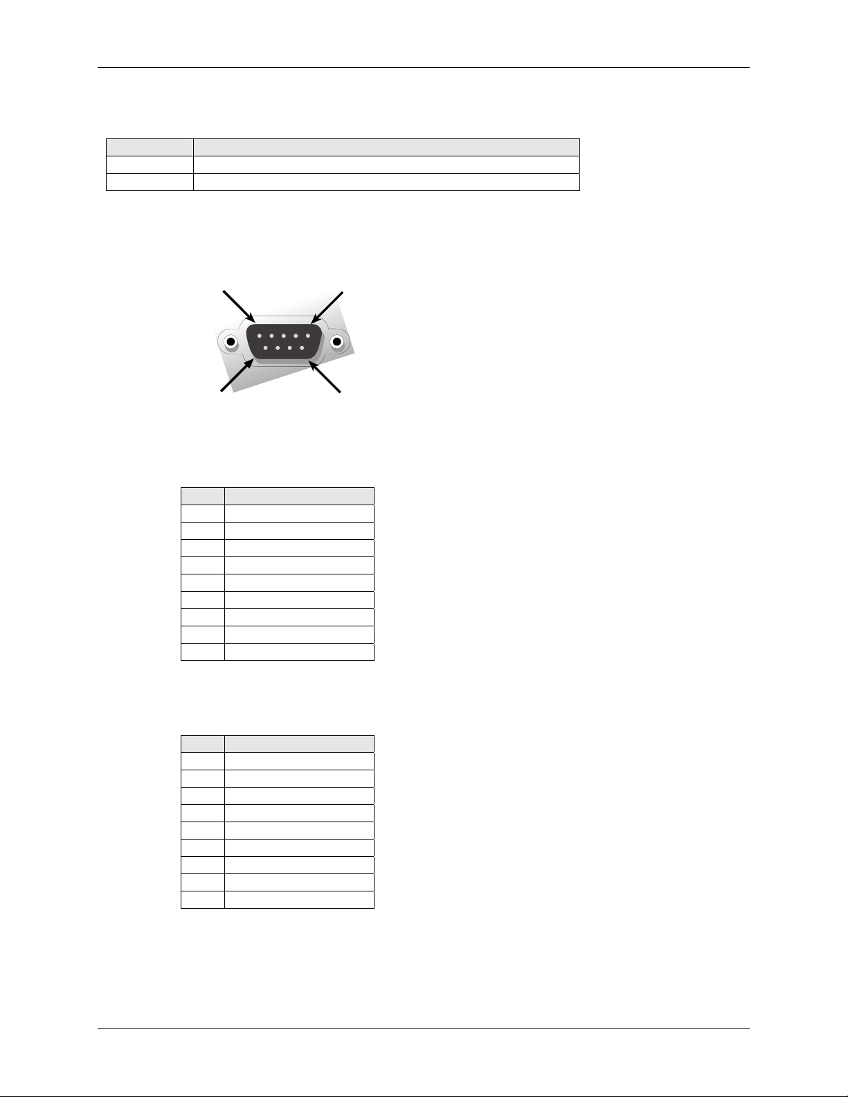
RS-232 9-Pin Connector Pinout
Pin 1
Pin 6
Pin 5
Pin 9
Pins for the Serial-to-Serial Adapter when Power Is Supplied Externally
Pin Description
1 DCD
2 RX Data
3 TX Data
4 DTR
5 Ground
6 DSR
7 RTS
8 CTS
9 RI
Pins for the Serial-to-Serial Adapter when Power Is Supplied Through the RS-232 Pin
Pin Description
1 DCD
2 RX Data
3 TX Data
4 DTR
5 Ground
6 Power
7 RTS
8 CTS
9 RI
Multi-Tech Systems, Inc. MultiConnect Serial-to-Serial Adapter User Guide (S000354A) 10
Page 11
Chapter 2 – Installation
Chapter 2 – Installation
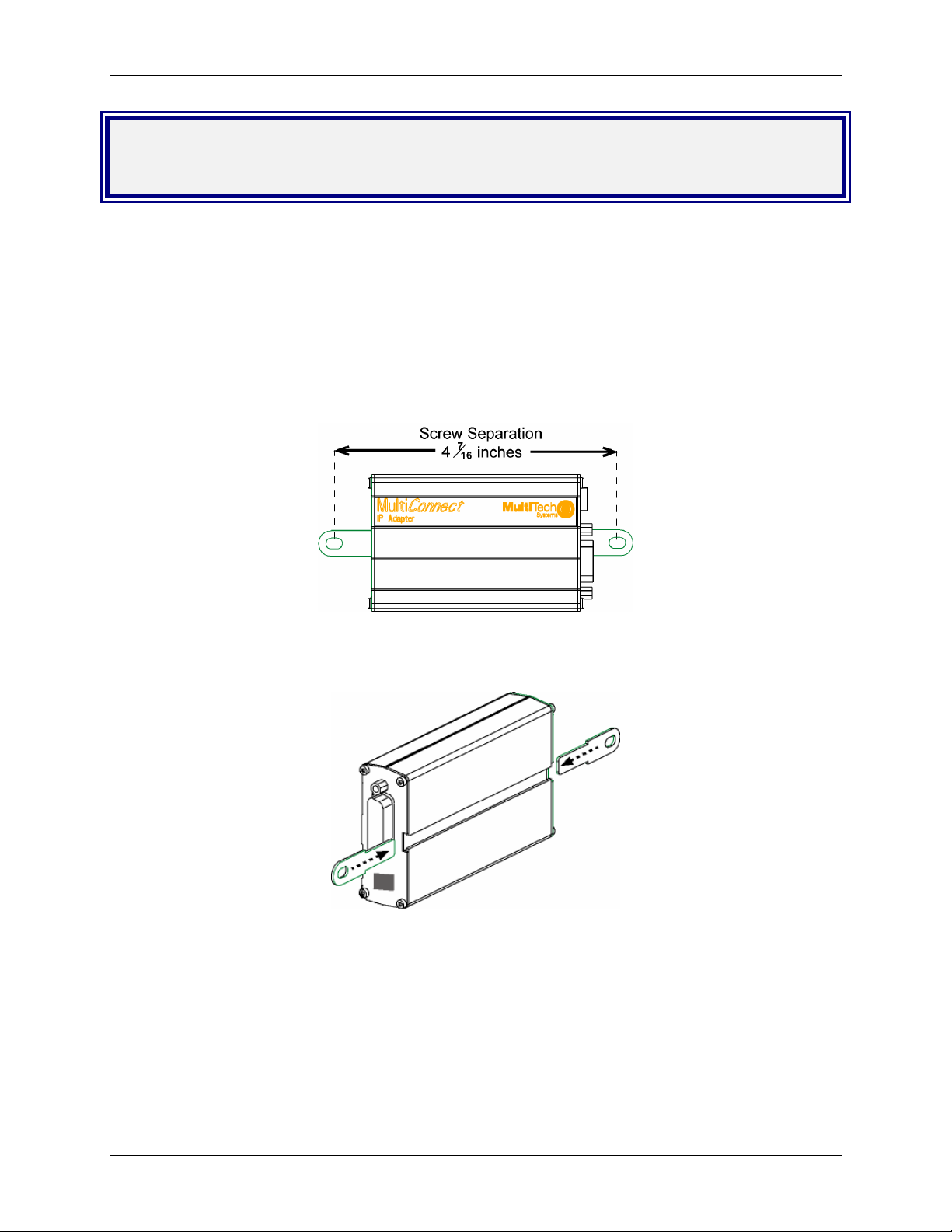
Attaching the MultiConnect to a Fixed
Location
The MultiConnect adapter is design to be used on the desktop or to be panel-mounted. To attach the
bracket for panel-mounting, following these steps:
1. Typically, the MultiConnect adapter is mounted against a flat surface with two mounting screws. Drill
the mounting holes at the desired location. The mounting holes must separated by 4 -7/16 inches
center-to-center.
2. To attach the brackets to the MultiConnect, slide the mounting brackets into the corresponding slots
on the back of the MultiConnect chassis.
3. Attach the adapter to the surface with two screws.
Multi-Tech Systems, Inc. MultiConnect Serial-to-Serial Adapter User Guide (S000354A) 11
Page 12
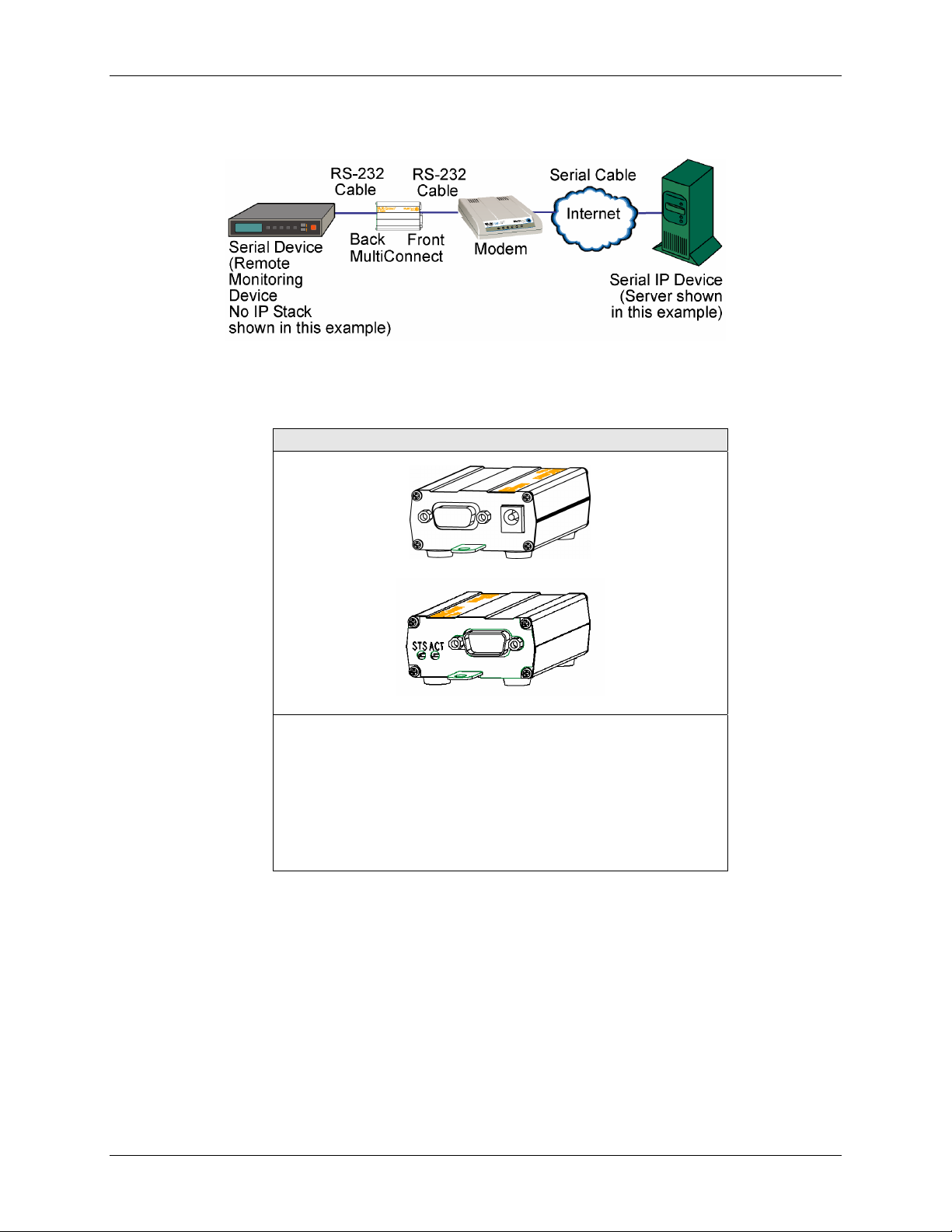
Serial-to-Serial Adapter Installation
Chapter 2 – Installation
Connecting the Cables
Serial-to-Serial Adapter
Back shown with External Power Option
1. Plug one end of the RS-232 cable into the front of the
Serial-to-Serial adapter.
Plug the other end into the RS-232 connector on the modem
that is setup with an Internet connection.
2. Plug one end of the other RS-232 cable into the back of the
Serial-to-Serial adapter.
Plug the other end into the RS-232 connector on the serial
device you want connected to the Internet.
Front
Multi-Tech Systems, Inc. MultiConnect Serial-to-Serial Adapter User Guide (S000354A) 12
Page 13

Chapter 2 – Installation
Connecting the Power
The adapters are powered in one of two ways:
• Through the DSR Pin of the RS-232 Cable
Adapters powered this way are shipped with an RS-232 cable that has a power pin instead of a
DSR pin.
• Through an External Power Supply
Adapters powered this way are shipped with a universal power supply and its accompanying power
cord and an RS-232 cable that has a DSR pin instead of a power pin.
Connecting the External Power
1. Plug the power supply cable with attached transformer block into the power connector on the
back of the MultiConnect adapter.
2. Plug the AC cord receptacle into the transformer block. Plug the other end into a power outlet.
One end of
RS-232
Shown
Here
Plug Power Supply Cable with
Transformer into the Back of
the Adapter
Plug AC Cord into
Transformer Block
and Outlet
Multi-Tech Systems, Inc. MultiConnect Serial-to-Serial Adapter User Guide (S000354A) 13
Page 14

Chapter 3 – Managing and Configuring the MultiConnect Adapter
Chapter 3 – Managing and
Configuring the MultiConnect
Adapter
Two Ways to Login
Login Using TTY
• Use TTY to configure your MultiConnect IP for the first time. Configure the host serial port
using the defaults listed below:
Baud: 115.2K
Data: 8
Parity: N
Stop: 1
Flow-Control: None
• Press the Enter key three times to get to the Login prompt or send three carriage returns.
• At the Login prompt, type admin.
At the Password prompt, type admin.
Important: The user name and password are case sensitive. They must be typed in lowercase
letters.
Login Using Telnet through the PPP Interface
• Open the PPP interface on the modem port.
• Upon successful establishment of a Telnet session, the MultiConnect IP displays the Login
prompt.
At the Login prompt, type admin.
At the Password prompt, type admin.
• After a successful login, the MultiConnect IP enters Command Mode. In Command Mode,
the MultiConnect IP can be configured and managed using the Command Line Interface
(CLI) command set.
About Command Mode and Data Mode
• In Command Mode, a # sign designates the prompt. If you type the word Help at the command
prompt, a complete list of commands displays.
• If you type the word Usage at the command prompt, a list of the command semantics displays.
• In Data Mode, the # sign is not displayed.
• To leave Command Mode, exit your terminal or Telnet session or type the word Exit at the
command prompt.
Note: See the Restore command and IP Escape String command.
Multi-Tech Systems, Inc. MultiConnect Serial-to-Serial Adapter User Guide (S000354A) 14
Page 15

Chapter 4 – Command Line Interface (CLI)
Chapter 4 – Command Line Interface
(CLI)
The MultiConnect commands are grouped based on the functionality.
• General Setup Commands
• IP Setup Commands
• Serial Setup Commands
• PPP Setup Commands
• HTTP Setup Commands
• SMTP Setup Commands
• POP3 Setup Commands
• FTP Client Setup Commands
• SNTP Client Setup Commands
General Notes
• Required command parameters are indicated between < >.
• Optional command parameters are indicated between [ ].
• Parameter choices are delineated by /.
• Upon successful execution of a command, the “OK” string is echoed to the client.
• When an unsuccessful command is executed, an appropriate error message is displayed
followed by an "ERROR" string.
• All the commands are case sensitive (they must be typed in lower case).
• PPP is enabled on the modem interface S1.
• All serial-related applications such as dial-in and dial-out are with respect to the serial
interface S0.
• The PPP interface is the modem interface S1.
Multi-Tech Systems, Inc. MultiConnect Serial-to-Serial Adapter User Guide (S000354A) 15
Page 16

Chapter 4 – Command Line Interface (CLI)
General Commands – Setup
General Setup Commands
General setup of a MultiConnect IP is port-independent (physical S0, S1 etc.). The following command
set is used to set the global configuration of MultiConnect IP.
Command Syntax dialout serial s0
Description
Default Value
Success
Error 1. Too few arguments
Command Syntax Exit
Description
Default Value
Success
Manual Telnet dialout (Internet-to-serial connectivity).
Invoked from the command shell.
NA
OK
“Usage: dialout serial <serial port>
Type ‘dialout ?’ for more information”
2. Invalid argument
Possible argument(s) are: Serial
1. When invoked from Serial Shell
This command is not supported through serial dial-in
Exits the command parser, unlocks the configurations, terminates session.
NA
OK
Command Syntax Help
Description
Default Value
Success
Command Syntax restore default-config
Description
Default Value
Success
Error 1. Too few arguments
Command Syntax restore session
Description
Default Value
Success
Error 1. Too few arguments
Provides the first level of commands in MultiConnect IP.
NA
OK
Restores the factory defaults.
Note: All previous configurations will be lost upon invoking this command.
The changes are made permanent only if save config is invoked.
NA
OK
”Possible arguments are default-config and session
2. Invalid argument
Invalid argument “invalid string”
Valid arguments are default-config and session
On Telnet dialout, the control is transferred to the command parser passing
the escape sequence “+++ inet”. Invoking “restore session” would resume
the Telnet dialout exiting the command parser.
NA
OK
Possible arguments are default-config and session
2. ERROR: Session not opened
Multi-Tech Systems, Inc. MultiConnect Serial-to-Serial Adapter User Guide (S000354A) 16
Page 17

Command Syntax reset modem
Description
Default Value
Success
At will, reset the built-in modem.
NA
OK
Error 1. Too few arguments Possible argument(s) are modem
Command Syntax save
Description
Default Value
Success
Command to Save the configuration to the flash and reboot.
NA
OK
Command Syntax telnet <dial-ip-addr> [<port>]
Description
Manual serial dial-in (device port to modem port connectivity).
Invoked from the command shell.
Default Value
Success
NA
OK
Error 1. Too few arguments
2. Invalid IP address/Port
“(Error: hostp = “configured host“. Error: hostp=“configured IP address“
3. When invoked from Command shell connected through
This command is not supported through Telnet
Command Syntax Usage
Description
Default Value
Success
Provides the command semantics for all the commands.
NA
OK
Command Syntax user add <user-name> [<passwd>]
Description
Add the user name and the password to the group.
Notes: Default Groups: admin, users
Default Users: admin, ipmodule
Only Admin can configure the MultiConnect IP
Default Value
Success
NA
OK
Error 1. Too few arguments
“Too few arguments. Possible value(s) are username followed by
password“
2. Unable to add the user name: “user ‘username‘ exists“
Command Syntax user delete <user-name>
Description
Default Value
Success
Delete the user name from the group.
NA
OK
Error 1. Too few arguments
“Too few arguments. Possible value(s) are username followed by
password“
2. Unable to delete the user name: “user ‘username‘ does not exist“
Chapter 4 – Command Line Interface (CLI)
General Commands – Setup
Telnet
Multi-Tech Systems, Inc. MultiConnect Serial-to-Serial Adapter User Guide (S000354A) 17
Page 18

Chapter 4 – Command Line Interface (CLI)
Command Syntax user password <username> <new password>
Description
Default Value
Success
Change the password for a user.
NA
OK
Error 1. Too few arguments
“Too few arguments. Possible value(s) are username followed by
password”
2. Unable to change the password
“Password does not match
Unable to change user <username> password”
Command Syntax set operation-mode <modem/ipmodule>
Description modem - In the modem mode, the target functions like a modem
ipmodule - In the ipmodule mode, all the functional features of
MultiConnect IP can be achieved.
Default Value
Success
Ipmodule
OK
Error 1. Too few arguments
"Too few arguments. Possible argument(s) are modem and ipmodule
2. Invalid string
"Invalid argument "string"
Valid argument(s) are modem and ipmodule
Command Syntax set boot-messages <enable/disable>
Description enable - Prints the boot-messages during module boot-up.
disable - Suppresses the boot-messages during module boot-up.
Default Value
Success
Enable
OK
Error 1. Too few arguments
"Too few arguments. Possible argument(s) are disable and enable
2. Invalid string
"Invalid argument "string"
Valid argument(s) are disable and enable
Command Syntax set date <DD/MM/YYYY>
Description
Default Value
Success
Sets the system date.
Jan 1 1970
OK
Error 1. Too few arguments
Usage: set date DD/MM/YYYY
Type 'set date ?' for more information
Error: Date in DD/MM/YYYY format
Too few arguments. Possible argument(s) are
ip ppp date
serial login time
General Commands – Setup
Multi-Tech Systems, Inc. MultiConnect Serial-to-Serial Adapter User Guide (S000354A) 18
Page 19

Chapter 4 – Command Line Interface (CLI)
Command Syntax set login
Description
Prompts the Login for the command shell when enabled, and doesn't when
disabled.
Default Value
Success
Enable
OK
Error 1. Too few arguments
"Usage: set login <enable/disable>
Type 'set login ?' for more information"
2. Invalid string
"error: set login <enable/disable>"
Command Syntax set login auto-dialout-login <enable/disable>
Description
Default Value
Success
Enables/Disables authentication for Telnet auto-dialout.
Disable
OK
Error 1. Too few arguments
"Usage: set login auto-dialout-login <enable/disable>
Type 'set login auto-dialout-login ?' for more information"
2. Invalid string
"error: set login auto-dialout-login <enable/disable>"
Command Syntax set time <HH:MM:SS>
Description
Default Value
Success
Sets the system time.
00:00:00
OK
Error 1. Too few arguments
Usage: set date HH:MM:SS
Type 'set date ?' for more information
Error: Time in HH:MM:SS format
Too few arguments. Possible argument(s) are
ip login
serial date
ppp time
Command Syntax set watchdog <enable/disable>
Description
Enables/Disables the watchdog timer.
The timer value is set to 6.5 seconds. This is the upper threshold value.
Note: Watchdog timer comes into effect only after reboot. Hence,
invoking this command calls for a reboot on save.
Default Value
Success
Enable
OK
Error 1. Too few arguments
"Usage: set watchdog <enable/disable>
Type 'set watchdog <enable/disable> ?' for more information"
2. Invalid string
"error: set watchdog <enable/disable>"
General Commands – Setup
Multi-Tech Systems, Inc. MultiConnect Serial-to-Serial Adapter User Guide (S000354A) 19
Page 20

Command Syntax show buildrun
Description Command Line Configuration - History.
Upon invoking any command, either through Telnet or Serial TTY, the
command is added to the buildrun file. This is very useful in case of
version updates.
Default Value
Success
NA
OK
Error 1. Too few arguments
"Too few arguments. Possible argument(s) are
serial date statistics users
buildrun ip sys-info
configuration ppp time
2. Invalid argument
Invalid argument "string". Valid arguments are
serial date statistics users
buildrun ip sys-info
configuration ppp time
Command Syntax show configuration
Description
Default Value
Success
Displays the MultiConnect IP configuration.
NA
OK
Error 1. Too few arguments
“Too few arguments. Possible argument(s) are:
2. Invalid argument
Valid arguments are:
Chapter 4 – Command Line Interface (CLI)
General Commands – Setup
General Commands – Show
serial ppp sys-info device-parameter
configuration recv-mail time
date http users
buildrun statistics send-mail
serial ppp sys-info device-parameter
configuration recv-mail time
date http users
buildrun statistics send-mail
Command Syntax show date
Description
Default Value
Success
Shows the system date.
NA
OK
Error 1. Too few arguments
Too few arguments. Possible argument(s) are:
ip statistics users
configuration ppp sys-info
date serial time
2. Invalid argument
Invalid argument "Invalid string". Valid arguments are
ip statistics users
configuration ppp sys-info
date serial time
Multi-Tech Systems, Inc. MultiConnect Serial-to-Serial Adapter User Guide (S000354A) 20
Page 21

Command Syntax show statistics
Description
Default Value
Success
Displays MultiConnect IP statistics.
NA
OK
Error 1. Too few arguments
“Too few arguments. Possible argument(s) are:
2. Invalid argument
Command Syntax show sys-info
Description
Displays the system related information.
• Hardware information
• System Uptime
• Memory Utilization
• Flash Memory Map
Default Value
Success
NA
OK
Error 1. Too few arguments
Too few arguments. Possible argument(s) are:
2. Invalid argument
Invalid argument "Invalid string". Valid arguments are:
Command Syntax show time
Description
Default Value
Success
Displays the system time.
NA
OK
Error 1. Too few arguments
Too few arguments. Possible argument(s) are
2. Invalid argument
Invalid argument "Invalid string"
Valid arguments are:
Chapter 4 – Command Line Interface (CLI)
General Commands – Show
ip statistics users
configuration ppp sys-info
date serial time
Valid arguments are:
ip statistics users
configuration ppp sys-info
date serial time
ip statistics users
configuration ppp sys-info
date serial time
ip statistics users
configuration ppp sys-info
date serial time
serial ip sys-info
configuration ppp time
date statistics users
serial ip sys-info
configuration ppp time
date statistics users
Multi-Tech Systems, Inc. MultiConnect Serial-to-Serial Adapter User Guide (S000354A) 21
Page 22

Command Syntax show users
Description
Default Value
Success
Error 1. Too few arguments
Chapter 4 – Command Line Interface (CLI)
General Commands – Show
Displays the configured users.
NA
OK
“Too few arguments. Possible argument(s) are:
serial ip sys-info
configuration ppp time
date statistics users
2. Invalid argument
Valid arguments are:
serial ip sys-info
configuration ppp time
date statistics users
Multi-Tech Systems, Inc. MultiConnect Serial-to-Serial Adapter User Guide (S000354A) 22
Page 23

IP Setup Commands
Command Syntax set ip dns <enable/disable>
Description
Default Value
Success
Error 1. Too few arguments
Command Syntax set ip hostname <hostname>
Description
Default Value
Success
Error 1. Too few arguments
Command Syntax set ip pri-dns <ip addr>
Description
Default Value
Success
Error 1. Too few arguments
Command Syntax set ip sec-dns <ip addr>
Description
Default Value
Success
Error 1. Too few arguments
Command Syntax set ip syslogd <enable/disable>
Description
Default Value
Success
Error 1. Too few arguments
Enables/disables the DNS client.
Enabled
OK
“Usage: set ip dns <enable/disable>
Type ‘set ip dns ?’ for more information”
2. Invalid string
Type ‘set ip dns ?’ for more information”
Sets the host name of the MultiConnect IP.
“MultiConnectIP”
OK
“Usage: set ip hostname <hostname>
Type ‘set ip hostname ?’ for more information”
Sets the primary DNS IP address to 0.0.0.0.
0.0.0.0
OK
“Usage: set ip pri-dns <ip addr>
Type ‘set ip pri-dns ?’ for more information”
2. Invalid IP Address
“error: Invalid IP address
Type ‘set ip pri-dns ?’ for more information”
Sets the secondary DNS IP address to 0.0.0.0.
0.0.0.0
OK
“Usage: set ip sec-dns <ip addr>
Type ‘set ip sec-dns ?’ for more information”
2. Invalid IP Address
“error: Invalid IP address
Type ‘set ip sec-dns ?’ for more information”
Enables/Disables syslogd.
Disable
OK
“Usage: set ip syslogd <enable/disable>
Type ‘set ip syslogd ?’ for more information”
Chapter 4 – Command Line Interface (CLI)
IP Commands – Setup
Multi-Tech Systems, Inc. MultiConnect Serial-to-Serial Adapter User Guide (S000354A) 23
Page 24

Command Syntax set ip syslogd-server <ip addr>
Description
Default Value
Success
Sets the remote syslog server's IP address.
0.0.0.0
OK
Error 1. Too few arguments
“Usage: set ip syslogd-server <ip_addr>
Type ‘set ip syslogd-server ?’ for more information”
2. Invalid IP address
“error: Invalid IP address
Type ‘set ip syslogd-server ?’ for more information”
Command Syntax set ip tcp-keepalive <t mins>
Description
Sets the TCP keep-alive timeout for the MultiConnect IP.
't' : range from 3-120 minutes
Default Value
Success
3 minutes
OK
Error 1. Too few arguments
“Usage: set ip tcp-keepalive <t mins>
Type ‘set ip tcp-keepalive ?’ for more information”
2. Invalid IP address
“error: Invalid value, rante [3-120] mins
Type ‘set ip tcp-keepalive ?’ for more information”
Command Syntax set ip telnet <enable/disable>
Description
Enables/disables the Telnet Server. This is a global setting, which will
enable/disable the Telnet Server in the MultiConnect IP.
Note: Upon disabling Telnet server, the administrator cannot configure the
MultiConnect IP over the built-in Modem interface (wherein PPP has
acquired IP Address). The only option is to connect through a terminal
application over the Serial port.
Default Value
Success
Enabled
OK
Error 1. Too few arguments
Too few arguments. Possible argument(s) are
set ip telnet<enable/disable>
Type : set ip telnet ? for more information)
2. Multiple matches
telnet
telnet-port
3. Invalid String
Invalid argument "invalid string"
Valid arguments are
auto-dialout escape-string
inactivity inactivity-timeout
escape-monitor raw-mode
Possible value(s) are enable or disable
Chapter 4 – Command Line Interface (CLI)
IP Commands – Setup
Multi-Tech Systems, Inc. MultiConnect Serial-to-Serial Adapter User Guide (S000354A) 24
Page 25

Chapter 4 – Command Line Interface (CLI)
Command Syntax set ip telnet auto-dialout <enable/disable>
Description
Enables Telnet connectivity between the MultiConnect IP and the remote
device.
This flag enables/disables the Telnet Auto dialout globally.
Default Value
Success
Enabled
OK
Error 1. Too few arguments
“Usage: set ip telnet auto-dialout <enable/disable>
Type ‘set ip telnet auto-dialout ?’ for more information”
2. Invalid String
Type ‘set ip telnet auto-dialout ?’ for more information”
Command Syntax set ip telnet escape-string <string>
Description
The Telnet Server scans for this escape sequence and transfers the control
to the command parser.
By default, the Telnet Server scans for “+++inet”.
Default Value
Success
+++ inet
OK
Error 1. Too few arguments
“Usage: set ip telnet escape-string <string>
Type ‘set ip telnet escape-string ?’ for more information”
2. Multiple matches
escape-monitor
escape-string
Command Syntax set ip telnet escape-monitor <enable/disable>
Description
Default Value
Success
Enables/disables the ‘‘monitor’’ flag that scans for the escape sequence.
Enabled
OK
Error 1. Too few arguments
“Usage: set ip telnet escape-monitor <enable/disable>
Type ‘set ip telnet escape-monitor ?’ for more information”
2. Multiple matches
escape-monitor
escape-string
3. Invalid String
Type ‘set ip telnet escape-monitor ?’ for more information”
Command Syntax set ip telnet inactivity <enable/disable>
Description
Default Value
Success
Enables/disables the inactivity functionality.
Disable
OK
Error 1. Too few arguments
“Usage: set ip telnet inactivity <enable/disable>
Type ‘set ip telnet inactivity ?’ for more information”
2. Multiple matches
inactivity
inactivity-timeout
3. Invalid String
Type ‘set ip telnet inactivity ?’ for more information”
IP Commands – Setup
Multi-Tech Systems, Inc. MultiConnect Serial-to-Serial Adapter User Guide (S000354A) 25
Page 26

Command Syntax set ip telnet inactivity-timeout <t secs>
Description
If the Telnet session is inactive for ‘t’ secs, the connection is terminated.
This functionality is applicable only if “set telnet inactivity” is enabled. (Refer
to ’set ip telnet inactivity’ command).
Default Value
Success
5 min
OK
Error 1. Too few arguments
“Usage: set ip telnet inactivity-timeout <t secs>
Type ‘set ip telnet inactivity-timeout ?’ for more information”
2. Multiple matches
inactivity and inactivity-timeout
3. Invalid timeout value
“error: ‘t secs range : 0 – 300
Type ‘set ip telnet inactivity-timeout ?’ for more information”
Command Syntax set ip telnet-port <port_num >
Description
This Telnet-port corresponds to the port number that the MultiConnect IP
will wait on for configuring the box.
Default port number is TCP 23. You have the option to change this number.
Note: Invoking this command terminates the current Telnet session.
Default Value
Success
23
OK
Error 1. Too few arguments
“Usage: set ip telnet-port <port-num>
Type ‘set ip telnet-port ?’ for more information”
2. Invalid port-num
“error: Invalid port number
Type ‘set ip telnet-port ?’ for more information”
Command Syntax set ip telnet raw-mode <enable/disable>
Description
This is a global setting of raw-mode for the Telnet application. This setting is
applicable for both Telnet auto-dialout, serial auto-dial-in.
Default Value
Success
Disabled
OK
Error 1. Too few arguments
“Usage: set ip telnet raw-mode <enable/disable>
Type ‘set ip telnet raw-mode ?’ for more information”
2. Invalid String
ERROR
Chapter 4 – Command Line Interface (CLI)
IP Commands – Setup
Command Syntax set ip tftp <enable/disable >
Description
Enables/disables the TFTP Server. When the TFTP Server is enabled, the
network administrator can upload the firmware to the flash.
Default Value
Success
Enabled
OK
Error 1. Too few arguments
“Usage: set ip tftp <enable/disable>
Type ‘set ip tftp ?’ for more information”
2. Invalid string
error: Invalid string
Type ‘set ip tftp ?’ for more information”
Multi-Tech Systems, Inc. MultiConnect Serial-to-Serial Adapter User Guide (S000354A) 26
Page 27

Chapter 4 – Command Line Interface (CLI)
Serial Commands – Setup
Serial Setup Commands
Command Syntax set serial auto-telnet <enable/disable>
Description
Default Value
Success
Error 1. Too few arguments
Command Syntax set serial <serial-interface> escape-monitor <enable/disable>
Description
Default Value
Success
Error 1. Too few arguments
Command Syntax set serial <serial-interface> escape-string <string>
Description
Default Value
Success
Error 1. Too few arguments
This command globally enables serial auto dial-in support.
Notes:
This feature provides a Telnet session to the serial device connected to S0
through the IP-enabled modem port (S1)
Also, Telnet can be used only after PPP is up and has acquired an IP
address on the modem's (S1) port.
Disabled
OK
“Usage: set serial auto-telnet <enable/disable>
Type ‘set serial auto-telnet ?’ for more information”
2. Invalid string
error: Invalid string
Type ‘set serial auto-telnet ?’ for more information
Sets a ‘‘monitor’’ flag that enables/disables the scanning of escape
sequence.
Enable
OK
“Usage: set serial s0/s1 escape-monitor <enable/disable>
Type ‘set serial s0/s1escape-monitor ?’ for more information”
2. Multiple matches
escape-monitor
escape-string
3. Invalid string
error: Invalid string
Type ‘set serial s0/s1 escape-monitor ?’ for more information”
The Telnet client scans for this escape sequence and transfers the control to
the command parser.
By default, the Telnet client scans for “+++inet”.
+++ inet<serial-interface>
OK
“Usage: set serial s0/s1 escape-string <string>
Type ‘set serial s0/s1 escape-string ?’ for more information”
2. Multiple matches
escape-monitor
escape-string
Multi-Tech Systems, Inc. MultiConnect Serial-to-Serial Adapter User Guide (S000354A) 27
Page 28

Command Syntax hangup [serial interface]
Valid serial interface – Modem port S1
Description
When this command is issued, the established live link is brought down.
This command is only valid only for modem port (S1)
Default Value
-
Success If physical link is brought down, OK and
Physical link is successfully brought down messages are given
Error 1. Too few arguments
"Usage: hangup [S1]
Type 'hangup [S1] ?' for more information"
2. “error: Link could not be brought down”
message is given when link could not be brought down
Command Syntax linkup [serial interface]
Valid serial interface – Modem port S1
Description
Establishes a physical link and PPP on the modem port.
This command is relevant only when the serial interface is a dialing end
with dialing-trig-mode configured as "command"
Default Value
Success
-
If physical link is established
OK and
CONNECT 14400 LAPM COMPRESSED
(i.e., CONNECT message from the modem)
are given
Error 1. Too few arguments
"Usage: linkup [S1]
Type 'linkup [S1]' for more information"
2. “error: Link cannot be brought up”
message is given when dialing-trig-mode is not "command”
3. “error: Link is not established”
message is given when link is not established (in case PPP fails to get the
logical link up)
4. “error: Link is already up”
message is given when link is established and this command will not
tear down and bring up the link
5. “error: NO CARRIER / NO DIALTONE / NO ANSWER”
or any error return code from the modem
Chapter 4 – Command Line Interface (CLI)
Serial Commands – Setup
Multi-Tech Systems, Inc. MultiConnect Serial-to-Serial Adapter User Guide (S000354A) 28
Page 29

Chapter 4 – Command Line Interface (CLI)
Command Syntax set serial [s0] auto-dialin <enable/disable>
Description
Enables/disables the device port to Internet connectivity for the serial port
S0. This command is valid only for device port S0
Default Value
Success
Disabled
OK
Error 1. Too few arguments
“Usage: set serial s0 auto-dialin <enable/disable>
Type ‘set serial s0 auto-dialin ? for more information”
2. Multiple matches
auto-dialin auto-dialin-protocol auto-dialout-protocol
auto-dialin-ipaddress auto-dialout
auto-dialin-port auto-dialout-port
3. Invalid string
“error: Invalid string
Type ‘set serial s0 auto-dial-in ? for more information”
4. If “set serial s1 auto-dialin <enable/disable>” is given
“error: Command not supported on the modem port s1”
Command Syntax set serial [s0] auto-dialin-ipaddress <ipaddr>
Description
Specifies the auto dial-in IP address.
Note: When a connection is established from serial, a session is
established to the IP address mentioned above.
This command is valid only for device port S0.
Default Value
Success
NULL
OK
Error 1. Too few arguments
“Usage: set serial s0 auto-dialin-ipaddress <ipaddr>
Type ‘set serial s0 auto-dialin-ipaddress ? for more information”
2. Multiple matches
auto-dialin auto-dialin-protocol auto-dialout-protocol
auto-dialin-ipaddress auto-dialout
auto-dialin-port auto-dialout-port
3. Invalid IP Address
“error: Invalid IP address
Type ‘show serial s0 auto-dialin-ipaddress ? for more information”
4. If “set serial s1 auto-dialin-ipaddress 192.168.2.2” is given
“error: Command not supported on the modem port s1”
Serial Commands – Setup
Multi-Tech Systems, Inc. MultiConnect Serial-to-Serial Adapter User Guide (S000354A) 29
Page 30

Chapter 4 – Command Line Interface (CLI)
Command Syntax set serial [s0] auto-dialin-port [port_num]
Description
Command to specify the auto dial-in port number.
Note: [port_num] is optional here. If port_num is not specified, the standard
port 23 of the Telnet protocol shall be used.
This command is valid only for device port S0
Default Value
Success
23
OK
Error 1. Too few arguments
“Usage: set serial s0 auto-dialin-port [port_num]
Type ‘set serial s0 auto-dialin-port ? for more information”
2. Multiple matches
auto-dialin auto-dialin-protocol auto-dialout-protocol
auto-dialin-ipaddress auto-dialout
auto-dialin-port auto-dialout-port
3. Invalid port
“error: Invalid port number
Type ‘set serial s0 auto-dialin-port ? for more information”
4. If “set serial s1 auto-dialin-port 23” is given
“error: Command not supported on modem port s1”
Serial Commands – Setup
Command Syntax set serial [s0] auto-dialin-protocol <telnet>
Description
By default, Telnet is the protocol used to establish the serial-to-Internet
connectivity.
Note: This syntax provides for future extensibility (SSH Client, etc.)
This command is valid only for device port S0<ftp protocol setting is not yet
implemented>
Default Value
Success
Error
Telnet
OK
1. Too few arguments
“Usage: set serial s0 auto-dialin-protocol <telnet/ftp>
Type ‘set serial s0 auto-dialin-protocol ? for more information”
2. Multiple matches
auto-dialin auto-dialin-protocol auto-dialout-protocol
auto-dialin-ipaddress auto-dialout
auto-dialin-port auto-dialout-port
3. Invalid protocol selected
“error: Selected protocol not supported
Type ‘set serial s0 auto-dialin-protocol ? for more information”
4. If “set serial s1 auto-dialin-protocol telnet” is given
“error: Command not supported on modem port s1”
Multi-Tech Systems, Inc. MultiConnect Serial-to-Serial Adapter User Guide (S000354A) 30
Page 31

Chapter 4 – Command Line Interface (CLI)
Serial Commands – Setup
Command Syntax set serial [s0] auto-dialin trig-mode <char/ dtr/ dtr-char/ none>
Description This mode is applicable only when auto dial-in is enabled on the serial port
S0. This command is valid only for device port S0.
Parameter Description
char
Initiate a session (Telnet) to the auto-dialin-ipaddress, only on a reception
of a character on the serial port S0.
dtr
Initiate a session (Telnet) to the auto-dialin-ipaddress, only on seeing a
DTR signal on the serial port S0
dtr-char
Initiate a session (Telnet) to the auto-dialin-ipaddress, either on reception
of a character (OR) seeing the DTR signal on the serial port S0.
none
Initiate a Telnet session to the auto-dialin-ipaddress on module boot-up.
Default Value
Success
dtr-char
OK
Error 1. Too few arguments
Too few arguments. Possible argument(s) are
char dtr-char
dtr none
2. Invalid string
“Invalid string "string"
Valid arguments are
char dtr-char
dtr none
3. If “set serial s1 auto-dialin trig-mode <char/dtr/dtr-char/none>” is given
“error: Command not supported on modem port s1”
Multi-Tech Systems, Inc. MultiConnect Serial-to-Serial Adapter User Guide (S000354A) 31
Page 32

Command Syntax set serial [s0] auto-dialout-port <port_num>
Description
If auto-dialout is enabled, specifies the auto dialout-port on which the client
can connect.
Default is 5000.
Note: The port number should be other than standard TCP ports.
This command is valid only for device port S0.
Default Value
Success
5000
OK
Error 1. Too few arguments
“Usage: set serial s0 auto-dialout-port <port_num>
Type ‘set serial s0 auto-dialout-port ? for more information”
2. Multiple matches
auto-dialin auto-dialin-protocol auto-dialout-protocol
auto-dialin-ipaddress auto-dialout
auto-dialin-port auto-dialout-port
3. Invalid Port Number
“error: Invalid port number
Type ‘set serial s0 auto-dialout-port ? for more information”
4. If “set serial s1 auto-dialout-port 5000” is given
“error: Command not supported on modem port s1”
Command Syntax set serial [s0] auto-dialout-protocol <telnet/>
Description Note:
This syntax gives a provision for future extensibility. <SSH Server, etc>.
This command is valid only for device port S0.
Default Value
Success
Telnet
OK
Error 1. Too few arguments
“Usage: set serial s0 auto-dialout-protocol <telnet/>
Type ‘set serial s0 auto-dialout-protocol ?’ for more information”
2. Multiple matches
auto-dialin auto-dialin-protocol auto-dialout-protocol
auto-dialin-ipaddress auto-dialout
auto-dialin-port auto-dialout-port
3. Invalid string
error: Invalid parameter
Type ‘set serial s0 auto-dialout-protocol ?’ for more information”
4. If “set serial s1 auto-dialout-protocol telnet” is given
“error: Command not supported on modem port s1”
Chapter 4 – Command Line Interface (CLI)
Serial Commands – Setup
Command Syntax set serial [s0/s1] baud-rate <baud>
Description
Default Value
Success
Sets the serial baud rate.
115200
OK
Error 1. Too few arguments
“Usage: set serial s0/s1 baud-rate <baud>
Type ‘set serial s0/s1 baud-rate ?’ for more information”
2. Invalid baud-rate
“error: baud-rate range : [300,……]
Type ‘set serial s0/s1 baud-rate ?’ for more information”
Multi-Tech Systems, Inc. MultiConnect Serial-to-Serial Adapter User Guide (S000354A) 32
Page 33

Chapter 4 – Command Line Interface (CLI)
Command Syntax set serial [s0/s1] buffer-datasize <0/d bytes>
Description
Default Value
Success
This command primarily buffers the data.
0 – No buffering.
OK
Error 1. Too few arguments
“Usage: set serial s0/s1 buffer-datasize <0/d bytes>
Type ‘set serial s0/s1 buffer-datasize ?’ for more information”
2. Multiple matches
buffer-datasize
buffer-time
3. Datasize range
“error: Buffer data-size range : [1 - 1500] bytes
Type ‘set serial s0/s1 buffer-datasize ?’ for more information”
Command Syntax set serial [s0/s1] buffer-time <0/t secs>
Description
This command is related to the ‘set serial s0/s1 buffer-datasize’ command.
The buffering of data shall either wait for datasize configured (in the previous
command) or time t secs.
Example:
Sl
Buffer-datasize
Default Value
Success
Error
Buffer-time (secs)
Descriptions
1
0 - Default
0 - Default
No buffering. Passes the data to the serial application on the reception of a
character on the serial application.
2
10
0
Buffer till it reaches buffer-datasize (10); then passes it to the serial application.
3
0
10
No buffering. Pass the data to the serial application on the reception of a
character on the serial.
4
10
10
Buffer the characters till it reaches the buffer-datasize (10)
(OR)
wait for the buffer-time (10Secs).
The data is passed on to the serial application depending on which condition is
satisfied first.
0 – No buffering
OK
1. Too few arguments
“Usage: set serial s0/s1 buffer-time <0/t secs>
Type ‘set serial s0/s1 buffer-time ?’ for more information”
2. Multiple matches
buffer-datasize
buffer-time
3. Time limit
“error: Time limit supported : <1 – 60 secs>
Type ‘set serial s0/s1 buffer-time ?’ for more information”
Serial Commands – Setup
Multi-Tech Systems, Inc. MultiConnect Serial-to-Serial Adapter User Guide (S000354A) 33
Page 34

Chapter 4 – Command Line Interface (CLI)
Serial Commands – Setup
Command Syntax set serial [s0/s1] chat-script <line-num> <expect-string> <send-string>
Description
Sets expect and send strings for the chat script to act on the modem.
Triggers for a reboot upon save.
Important Note:
Use double quotes if more than one word is used in the
<expect-string>/<send-string>.
Default Value
Success
NA
OK
Error 1. Too few arguments
"Usage: set serial s0/s1 chat-script <line-num> <expect-string> <send-string>
Type 'set serial s0/s1 chat-script ?' for more information"
Command Syntax Set serial [s0/s1] connect-type <direct/modem>
Description
Sets the connect type of the serial port to direct/modem connect.
Note: Modem port (S1) will always have connect-type as modem since it is a
built-in modem
Default Value
Success
Direct
OK
Error 1. Too few arguments
“Usage: set serial s0/s1 connect-type <direct/modem>
Type ‘set serial s0/s1 connect-type ?’ for more information”
2. Invalid string
“error: Invalid string
Type ‘set serial s0/s1 connect-type ?’ for more information”
3. If “set serial s1 connect-type direct” is given
error: modem port s1 is a built-in modem interface; it cannot be set to direct
Command Syntax set serial [s0/s1] connect-state <answering/dialing/both>
Description
Default Value
Success
Sets the connect state of the serial port to answering/dialing/both state.
Both
OK
Error 1. Too few arguments
“Usage: set serial s0/s1 connect-state <answering/dialing/both>
Type ‘set serial s0/s1 connect-state ?’ for more information”
2. Invalid string
“error: Invalid string
Type ‘set serial s0/s1 connect-state ?’ for more information”
Command Syntax set serial [s0/s1] data-bits <7/8>
Description
Default Value
Success
Set the data-bits.
8
OK
Error 1. Too few arguments
“Usage: set serial s0/s1 data-bits <7/8>
Type ‘set serial s0/s1 data-bits ?’ for more information”
2. Invalid data-bit setting
“error: Data-bits range supported: [7/8]
Type ‘set serial s0/s1 data-bits ?’ for more information”
Multi-Tech Systems, Inc. MultiConnect Serial-to-Serial Adapter User Guide (S000354A) 34
Page 35

Chapter 4 – Command Line Interface (CLI)
Command Syntax Set serial [s0/s1] flow-control <none/rts-cts>
Description
Set the flow-control of the serial port. By default flow-control is disabled on
the serial port.
Default Value
Success
rts-cts
OK
Error 1. Too few arguments
“Usage: set serial s0/s1 flow-control <none/rts-cts>
Type ‘set serial s0/s1 flow-control ?’ for more information”
2. Invalid flow-control setting
“error: flow-control supported: [none/rts-cts]
Type ‘set serial s0/s1 flow-control ?’ for more information”
Command Syntax set serial [s0] host-interaction-mode <enable/disable>
Description
This parameter is set by the host to enable the host-interactive-mode.
When this mode is set, the host/serial device can use SMTP client, POP3
client, and HTTP server.
Host interaction mode is valid only for device port S0.
Note: Telnet Auto-Dialout and PPP cannot be enabled when this mode is
enabled.
Default Value
Success
Disable
OK
Error 1. Too few arguments
"Usage: set serial s0 host-interaction-mode <enable/disable>
Type set serial s0 host-interaction-mode ?”
2. Invalid string
Type set serial s0 host-interaction-mode ?”
3. Port used by Auto-dialout
“ERROR: Port used by Auto-dialout”
4. “set serial s1 host-interaction-mode s1” is given
“error: Command not supported on modem port s1”
Command Syntax set serial [s0/s1] modem connect-string <connect-str>
Description
Sets the Modem Connect string.
Triggers for a reboot upon save.
Note: The configured modem strings takes precedence over the
MODEM.CNF
Default Value
Success
CONNECT
OK
Error 1. Too few arguments
"Usage: set serial s0/s1 modem connect-string <connect-str>
Type 'set serial s0/s1 modem connect-string ?' for more information"
Command Syntax set serial [s0/s1] modem dial-number <phone-num>
Description
Default Value
Success
Sets the dial-number to be dialed.
NA
OK
Error 1. Too few arguments
"Usage: set serial s0/s1 modem dial-number <phone-num>
Type 'set serial s0/s1 modem dial-number ?' for more information"
Serial Commands – Setup
Multi-Tech Systems, Inc. MultiConnect Serial-to-Serial Adapter User Guide (S000354A) 35
Page 36

Chapter 4 – Command Line Interface (CLI)
Serial Commands – Setup
Command Syntax set serial [s0/s1] modem dial-prefix <dialprefix>
Description
Sets the Modem Dial-Prefix.
Triggers for a reboot upon save.
Note: The configured modem strings takes precedence over the
MODEM.CNF
Default Value
Success
ATDT
OK
Error 1. Too few arguments
"Usage: set serial s0/s1 modem dial-prefix <dialprefix>
Type 'set serial s0/s1 modem dial-prefix ?' for more information"
Command Syntax Set serial [s0/s1] modem dial-suffix <dialsuffix>
Description
Sets the Modem Dial-suffix. Triggers for a reboot upon save.
Note: The configured modem strings takes precedence over the
MODEM.CNF
Default Value
Success
^M
OK
Error 1. Too few arguments
"Usage: set serial s0/s1 modem dial-suffix <dialsuffix>
Type 'set serial s0/s1 modem dial-suffix ?' for more information"
Command Syntax Set serial [s0/s1] modem dialing-method <configuration/chat-script>
Description
Sets the modem dialing method.
1. Configuration method: The user shall provide only the dial-number to
reach.
2. Choosing the 'chat' as the dialing-method, the user can write his/her own
script by providing an Expect and a Send sequence.
Refer to: 'set serial s0/s1 chat-script ?' for providing an "Expect" and a
"Send" sequence.
Triggers for a reboot upon save.
Default Value
Success
Configuration
OK
Error 1. Too few arguments
"Usage: set serial s0/s1 modem dialing-method <configuration/chat-
script>
Type 'set serial s0/s1 modem dialing-method ?' for more information"
Multi-Tech Systems, Inc. MultiConnect Serial-to-Serial Adapter User Guide (S000354A) 36
Page 37

Chapter 4 – Command Line Interface (CLI)
Serial Commands – Setup
Command Syntax set serial [s1] modem dialing-trig-mode <none/dtr/command>
Description
Sets the dialing trigger mode for the modem port S1.
If dialing trig mode is none:
The serial interface will initialize the modem and dial as per the configured
parameters.
If dialing trig mode is dtr:
As soon as a serial device is connected to S0 (DTR goes high), the S1
serial interface will initialize the modem and dial as per the configured
parameters.
If dialing trig mode is command:
The serial interface will dial only on demand. The possible commands that
can trigger the link are:
• "linkup s1" command is issued
• Application trigger (SMTP, POP3 Client, etc)
Note: This command triggers a reboot upon save.
Default Value
Success
Command
OK
Error 1. Too few arguments
"Usage: set serial s1 modem dialing-trig-mode <none/dtr/command>
Type 'set serial s1 modem dialing-trig-mode ?' for more information"
2. Invalid string
"error: Invalid string
Type 'set serial s1 modem dialing-trig-mode ?' for more information"
Command Syntax set serial s1 modem country-code <value>
Description
Sets the modem country code value to <value>.
This command is valid only for port S1.
Default Value
Success
OK
Error 1. Too few arguments
“Usage: set serial s1 modem country-code value <value>
Type ‘set serial s1 modem country-code value ?’ for more information”
Command Syntax set serial [s0/s1] modem hangup-string <hangup-str>
Description
Sets the Modem hang-up string.
Triggers for a reboot upon save.
Default Value
Success
+++ATH0
OK
Error 1. Too few arguments
"Usage: set serial s0/s1 modem hangup-string <hang-str>
Type 'set serial s0/s1 modem hangup-string ?' for more information"
Multi-Tech Systems, Inc. MultiConnect Serial-to-Serial Adapter User Guide (S000354A) 37
Page 38

Chapter 4 – Command Line Interface (CLI)
Command Syntax set serial [s0/s1] modem init-string <init-num> <init-str>
Description
Configures the modem initial strings.
Init-num can range from 1-5.
Triggers for a reboot upon save.
Example: Set serial s0 modem init-string 1 ATZ
Set serial s0 modem init-string 1 "ATZ AT&F"
Important Note:
Use double quotes if more than one word is used in the <init-str>. Refer to
example 2 above. This holds true for all the following commands that need
a string as a parameter.
Default Value
Init-string 1 is set to 'ATZ'
Init-string 2 is set to ' '
Init-string 3 is set to ' '
Init-string 4 is set to ' '
Init-string 5 is set to ' '
Success
OK
Error 1. Too few arguments
"Usage: set serial s0/s1 modem init-string <init-num> <init-str>
Type 'set serial s0/s1 modem init-string ?' for more information"
Invalid init-num
"ERROR: init-num range supported : [1-5]"
Command Syntax set serial [s0/s1] modem ok-string <ok-str>
Description
Sets the modem OK string.
Triggers for a reboot upon save.
Default Value
Success
OK
OK
Error 1. Too few arguments
"Usage: set serial s0/s1 modem ok-string <ok-str>
Type 'set serial s0/s1 modem ok-string ?' for more information"
Command Syntax set serial [s0/s1] modem ring-string <ring-str>
Description
Default Value
Success
Sets the modem ring string. Triggers for a reboot upon save.
RING
OK
Error 1. Too few arguments
"Usage: set serial s0/s1 modem ring-string <ring-str>
Type 'set serial s0/s1 modem ring-string ?' for more information"
Serial Commands – Setup
Command Syntax set serial [s0/s1] parity <even/odd/none>
Description
Default Value
Success
Sets parity to even/odd/none.
None
OK
Error 1. Too few arguments
“Usage: set serial s0/s1 parity <even/odd/none>
Type ‘set serial s0/s1 parity ?’ for more information”
2. Invalid parity setting
“error: parity supported: [even/odd/none]
Type ‘set serial s0/s1 parity ?’ for more information”
Multi-Tech Systems, Inc. MultiConnect Serial-to-Serial Adapter User Guide (S000354A) 38
Page 39

Command Syntax set serial [s0] login-string <login-string>
Description
Sets a login-string to the serial port. This command is valid only for port S0.
The Login string can be of length maximum 8 characters.
Upon module boot-up, Login is displayed on the console only if the
characters entered match the login-string configured.
Note: This is applicable only if the "set serial s0 auto-dialin trig-mode" is
char
Default Value
Success
""
OK
Error 1. Too few arguments
“Usage: set serial s0 login-string <login-string>
Type ‘set serial s0 login-string ? for more information”
2. Invalid string
“ERROR: Invalid string
Type ‘set serial s0 login-string ? for more information”
3. If ‘set serial s1 login-string <login-string>’ is given
“error: Command not supported on modem port s1”
Command Syntax set serial [s0] raw-dialin <enable/disable>
Description
Enables/disables raw mode support for serial auto dial-in on the device port
S0.
Default Value
Success
Disabled
OK
Error 1. Too few arguments
“Usage: set serial s0 raw-dialin <enable/disable>
Type ‘set serial s0 raw-dialin ? for more information”
2. Multiple matches
raw-dialin
raw-dialout
3. Invalid string
“ERROR: Invalid string
Type ‘set serial s0 raw-dialin ? for more information”
If ‘set serial s1 raw-dialin <enable/disable>’ is given
“error: Command not supported on modem port s1”
Chapter 4 – Command Line Interface (CLI)
Serial Commands – Setup
Command Syntax set serial [s0] raw-dialout <enable/disable>
Description
Default Value
Success
Enables/disables raw mode support for auto dialout on the device port S0.
Disabled
OK
Error 1. Too few arguments
“Usage: set serial s0/s1 raw-dialout <enable/disable>
Type ‘set serial s0/s1 raw-dialout ? for more information”
2. Multiple matches
raw-dialin
raw-dialout
3. Invalid string
“error: Invalid string
Type ‘set serial s0/s1 raw-dialout ? for more information”
4. If ‘set serial s1 raw-dialout <enable/disable>’ is given
“error: Command not supported on modem port s1”
Multi-Tech Systems, Inc. MultiConnect Serial-to-Serial Adapter User Guide (S000354A) 39
Page 40

Command Syntax set serial [s0/s1] stop-bits <1/1.5/2>
Description
Default Value
Success
Sets the stop bits.
1
OK
Error 1. Too few arguments
“Usage: set serial s0/s1 stop-bits <1/1.5/2>
Type ‘set serial s0/s1 stop-bits ?’ for more information”
2. Invalid stop-bit setting
“ERROR: Stop-bit supported : [1, 1.5, 2]
Type ‘set serial s0/s1 stop-bits ?’ for more information”
Command Syntax show serial [s0/s1] chat-script
Description Displays the Expect and Send sequence for the serial port S0 or S1.
Default Value
Success
Error
NA
OK
1. Too few arguments
Possible value(s) are
statistics modem-configuration
configuration chat-script
Command Syntax show serial [s0/s1] configuration
Description
Default Value
Success
Displays serial S0/S1 configuration.
OK
Error 1. Too few arguments
Possible value(s) are
statistics modem-configuration
configuration chat-script
Command Syntax show serial [s0/s1] modem-configuration
Description
Default Value
Success
Displays the modem-related configuration for serial port S0 or S1.
NA
OK
Error 1. Too few arguments
Possible value(s) are
statistics modem-configuration
configuration chat-script
Chapter 4 – Command Line Interface (CLI)
Serial Commands – Setup
Serial Commands – Show
Multi-Tech Systems, Inc. MultiConnect Serial-to-Serial Adapter User Guide (S000354A) 40
Page 41

Command Syntax show serial [s0/s1] statistics
Description
Displays Serial Statistics.
• Status (If serial is used by any application)
• Rx Bytes
• Rx Errors
• Tx Bytes
• Tx Errors
• Status of EIA signals (CTS, DSR, DCD, RTS, DTR).
Important Note: Serial statistics are only for the current session. Rx
Bytes, Tx Bytes will be reset for every session opened on the serial.
Default Value
Success
-
OK
Error 1. Too few arguments
Possible value(s) are
statistics modem-configuration
configuration chat-script
Command Syntax show serial modem country code
This command is supported on S1 only.
Description
Default Value
Success
Displays the supported country codes for this product.
-
OK
Error 1. Too few arguments
Possible value(s) are
statistics modem-configuration chat-script
configuration country-code
Chapter 4 – Command Line Interface (CLI)
Serial Commands – Show
Multi-Tech Systems, Inc. MultiConnect Serial-to-Serial Adapter User Guide (S000354A) 41
Page 42

Chapter 4 – Command Line Interface (CLI)
PPP Commands – Setup
PPP Setup Commands
Note: All PPP Commands use the ppp0 interface, which corresponds to the modem port S1.
Command Syntax set ppp <interface> authentication <enable/disable>
Description
Default Value
Success
Error 1. Too few arguments
Command Syntax set ppp <interface> auth-type <pap/chap/pap-chap>
Description
Default Value
Success
Error 1. Too few arguments
Command Syntax set ppp <interface> compression <enable/disable>
Description
Default Value
Success
Error 1. Too few arguments
Command Syntax set ppp <interface> comp-type <both/bsd/deflate>
Description
Default Value
Success
Error 1. Too few arguments
Enables/disables PPP Authentication.
Disabled
OK
Possible argument(s) are disable and enable
2. Invalid string
Invalid argument.
Valid argument(s) are disable and enable
3. Multiple matches: auth-type and authentication
Sets the protocol to authenticate the remote peer: PAP/CHAP/PAP-CHAP
PAP
OK
Too few argument(s). Possible argument(s) are:
chap, pap, and pap-chap
2. Invalid authentication type
Invalid argument. Valid argument(s) are
chap, pap, and pap-chap
3. Multiple matches: auth-type and authentication
Enables/disables CCP compression.
Disabled
OK
Possible argument(s) are disable and enable
2. Invalid string
Invalid argument. Valid argument(s) are disable and enable
Sets the compression type to BSD, DEFLATE or BOTH.
In the case of NON-RAWMODE:
When both is configured as the compression type, the module tries to
negotiate DEFLATE first. In the event of failure, the BSD is negotiated.
In case of RAW-MODE:
Compress-type both is not supported in RAW-MODE, since there are no
negotiations between MultiConnect IP Modules.
Deflate
OK
Too few argument(s). Possible argument(s) are both, bsd, deflate
2. Invalid string
Invalid argument "string"
Valid argument(s) are both, bsd, deflate
Multi-Tech Systems, Inc. MultiConnect Serial-to-Serial Adapter User Guide (S000354A) 42
Page 43

Chapter 4 – Command Line Interface (CLI)
Command Syntax set ppp <interface> dialing-max-retries <0-100>
Description
Configures the maximum number of dialing retries.
Maximum dialing retry is 100
Default Value
Success
5
OK
Error 1. Too few arguments
“Usage: set ppp ppp0 dialing-max-retires [0-100](times)
Type ‘set ppp ppp0 dialing-max-retries ?’ for more information”
2. Multiple matches
dialing-max-retries and dialing-retry-interval
3. Retry range
“error: dialing-max-retries range : [0 - 100]
Type ‘set ppp ppp0 dialing-retry-interval ?’ for more information”
Command Syntax set ppp <interface> dialing-retry-interval <0-300>
Description
Configures the interval for the port to retry dialing.
Maximum dialing retry is 300.
Default Value
Success
15
OK
Error 1. Too few arguments
“Usage: set ppp ppp0 dialing-retry-interval [0-300](secs)
Type ‘set ppp ppp0 dialing-retry-interval ?’ for more information”
2. Multiple matches
dialing-max-retries and dialing-retry-interval
3. Retry range
“error: dialing-retry-interval range : [0 - 300]
Type ‘set ppp ppp0 dialing-retry-interval ?’ for more information”
Command Syntax set ppp <interface> idle-timeout <0-900>
Description Configures the dial-on-demand idle timeout value .Maximum dialing retry is
900 secs
Default Value
Success
600 secs
OK
Error 1. Too few arguments
“Usage: set ppp ppp0 idle-timeout <0-900>
Type set ppp ppp0 idle-timeout ?’ for more information”
2 Idle timeout range
“error: dod-idle-timeout range : [0 - 900]
Type ‘set ppp ppp0 idle-timeout ?’ for more information”
Command Syntax set ppp <interface> ipcp-mode <client-only/client-or-lan>
Description
Sets the IPCP mode-to-client-only or client or LAN.
Default Value client-only
Success
OK
Error 1. Too few arguments
Possible argument(s) are client-only and client-or-lan
2. Invalid string
Invalid argument.
Valid argument(s) are client-only and client-or-lan
PPP Commands – Setup
Multi-Tech Systems, Inc. MultiConnect Serial-to-Serial Adapter User Guide (S000354A) 43
Page 44

Chapter 4 – Command Line Interface (CLI)
Command Syntax set ppp <interface> local-ip-addr <ipaddr> mask <ipmask>
Description
During IPCP negotiations, the configured IP address is sent for the local
interface. In the case where the peer is requested to provide the IP
address, it can be configured as 0.0.0.0
Default Value
0.0.0.0
255.255.255.0
Success
OK
Error 1. Too few arguments
Possible arguments are IP Address and Mask
2. Invalid IP address/Mask
Invalid argument
Command Syntax set ppp <interface> password <password >
Description
Default Value
Success
Sets the password that remote peers will use for authentication.
Ipmodule
OK
Error 1. Password Length
Password should have minimum of 8 characters
PPP Commands – Setup
Command Syntax set ppp <interface> remote-ip-addr <ipaddr> mask <ipmask>
Description
During IPCP negotiations, this configured IP address is sent for the remote
interface. In the case of the peer being requested to provide the IP address,
it can be configured as 0.0.0.0
Default Value
0.0.0.0
255.255.255.0
Success
OK
Error 1. Too few arguments
Possible arguments are IP Address and Mask
2. Invalid IP address/Mask
Invalid argument
Command Syntax set ppp <interface> username <username>
Description
Default Value
Success
Sets the user name that the remote peer will use for authentication.
Ipmodule
OK
Error 1. Too few arguments
Possible value(s) are valid user name
Multi-Tech Systems, Inc. MultiConnect Serial-to-Serial Adapter User Guide (S000354A) 44
Page 45

Command Syntax show ppp ppp0 configuration
Description
Displays:
PPP Status (enabled/disabled)
Authentication status
Authentication type
Username and password for authentication
Compression status
Compression type
IPCP Mode
Local IP Address
Remote IP Address
Default Value
Success
Error
NA
OK
1. Too few arguments
Possible argument(s) are
configuration ip-addr
statistics link-status
2. Invalid argument
Invalid argument
Valid argument(s) are
configuration ip-addr
statistics link-status
Command Syntax show ppp <interface> ip-addr
Description
Displays:
Local IP Address
Remote IP Address
Default Value
Success
Error
NA
OK
1. Too few arguments
Possible argument(s) are
configuration ip-addr
statistics link-status
2. Invalid argument
Invalid argument
Valid argument(s) are
configuration ip-addr
statistics link-status
Command Syntax
Description
Default Value
Success
show ppp <interface> link-status
Displays the link status on ppp interface.
OK
Up / Down
Error
1. Too few arguments
Possible argument(s) are
configuration ip-addr
statistics link-status
2. Invalid argument
Invalid argument
Valid argument(s) are
configuration ip-addr
statistics link-status
Chapter 4 – Command Line Interface (CLI)
PPP Commands – Show
Multi-Tech Systems, Inc. MultiConnect Serial-to-Serial Adapter User Guide (S000354A) 45
Page 46

Command Syntax show ppp <interface> statistics
Description
Default Value
Success
Displays PPP Statistics.
OK
Error 1. Too few arguments
Possible argument(s) are
configuration ip-addr
statistics link-status
2. Invalid argument
Invalid argument
Valid argument(s) are:
configuration ip-addr
statistics link-status
Chapter 4 – Command Line Interface (CLI)
PPP Commands – Show
Multi-Tech Systems, Inc. MultiConnect Serial-to-Serial Adapter User Guide (S000354A) 46
Page 47

Chapter 4 – Command Line Interface (CLI)
HTTP Server Commands – Setup
HTTP Server Commands
The commands in this section are listed in the order in which they might be used.
Command Syntax set ip http-page <default/serial>
Description
Default Value
Success
Error 1. Too few arguments
Command Syntax set ip http <enable/disable>
Description This enables the http server on the MultiConnect IP to listen on Port 80.
Default Value
Success
Error 1. Too few arguments
Command Syntax set ip http-port <port>
Description
Default Value
Success
Error 1. Too few arguments
Command Syntax set device-parameter P<n> <value>
Description
Default Value
Success
Error 1. Too few arguments
This parameter is used by the http server to host the default HTML index or
host-defined http-serial-S0 HTML page.
Default
OK
“Usage: set ip http-page <default/serial>
Type set ip http-page ?”
2. Invalid string
Type "set ip http-page ?”
Disable
OK
“Usage: set "ip http <enable/disable>
Type 'set ip http ?' for more information"
2. Invalid string
"ERROR: Invalid string
Type 'set ip http ?' for more information"
Sets the HTTP server to listen on the specified port.
80
OK
“Usage: set ip http-port <port>
Type set 'ip http-port ?' for more information”
2. Invalid port number
"ERROR: Invalid port number
Type set 'ip http-port ?' for more information”
where n = 0 to 99.
Sets the value of the parameter from the host/serial device.
Value in the default parameter list file uploaded through TFTP.
OK
“Usage: set device P<n> <value>
Type 'set device P<n> ?' for more information”
2. Invalid string
"ERROR: Invalid string
Type 'set device P<n> ?' for more information”
Multi-Tech Systems, Inc. MultiConnect Serial-to-Serial Adapter User Guide (S000354A) 47
Page 48

Command Syntax save param
Description
Invoking this command will save the host parameters into the flash. The
“/var/apps” directory is gun zipped to apps.tar.gz and written into flash.
(APPS _SECTOR)
Default Value
Success
OK
Error 1. Too few arguments
“ERROR: Too few arguments
Type 'save ?' for more information”
Command Syntax show http configuration
Description
Default Value
Success
Displays the HTTP related configurations.
OK
Error 1. Too few arguments
“ERROR: Too few arguments
Type 'show http configuration ?' for more information”
Command Syntax show device-parameter P<n>
where n = 0 to 99.
Description
Default Value
Success
Displays the value of the requested parameter from MultiConnect IP.
OK
Error 1. Too few arguments
“ERROR: Too few arguments
Type 'show device-parameter ?' for more information”
Command Syntax show device-parameter modified
Description
Displays the status of the host parameters; for example, whether they are
changed by the browser.
Returns “Device parameters changed” when values are changed by the
remote browser.
Returns “Device parameters not changed” when values are not changed.
Default Value
Success
OK
Error 1. Too few arguments
“ERROR: Too few arguments
Type 'show device-parameter ?' for more information”
Chapter 4 – Command Line Interface (CLI)
HTTP Server Commands – Setup
HTTP Server Commands – Show
Multi-Tech Systems, Inc. MultiConnect Serial-to-Serial Adapter User Guide (S000354A) 48
Page 49

Chapter 4 – Command Line Interface (CLI)
SMTP Client Commands – Setup
SMTP Client Commands
The commands in this section are listed in the order in which they might be used.
Command Syntax set send-mail smtp-server-name <name/ip-address>
Description
Default Value
Success
Error 1. Too few arguments
Command Syntax set send-mail smtp-server-port <port>
Description
Default Value
Success
Error 1. Too few arguments
Command Syntax set send-mail host-name <host name>
Description
Default Value
Success
Error 1. Too few arguments
Command Syntax set send-mail from-address-identity <name>
Description
Default Value
Success
Error 1. Too few arguments
Command Syntax set send-mail from-address <email-address>
Description
Default Value
Success
Error 1. Too few arguments
Sets the SMTP server name or IP address. Server names must be such
that they can be resolved by the DNS.
NULL
OK
“Usage: set send-mail smtp-server-name <name/ip-address>
Type 'set send-mail smtp-server-name ?' for more information”
2. Invalid name/IP address
“ERROR: Invalid SMTP Server Name/IP Address”
Sets the SMTP Server port.
25
OK
“Usage: set send-mail smtp-server-port <port>
Type 'set send-mail smtp-server-port ?' for more information”
Sets the SMTP Client host name.
NULL
OK
“Usage: set send-mail host-name <host name>
Type 'set send-mail host-name ?' for more information”
Sets the ‘From:’ description in the email header as <name>.
NULL
OK
“Usage: set send-mail from-address-identity <name>
Type 'set send-mail from-address-identity ?' for more information”
Sets the email-address as the Default From address information.
NULL
OK
“Usage: set send-mail from-address <email-address>
Type 'set send-mail from-address ?' for more information”
Multi-Tech Systems, Inc. MultiConnect Serial-to-Serial Adapter User Guide (S000354A) 49
Page 50

Chapter 4 – Command Line Interface (CLI)
SMTP Client Commands – Setup
Command Syntax set send-mail to-address <n> <email-address> where n = 1 to 5.
Description
Sets the email-address as one of the primary addressee. This is the default
email address to which email messages are sent.
Default Value
Success
NULL
OK
Error 1. Too few arguments
“Usage: set send-mail to-address <n> <email-address>
Type 'set send-mail to-address <n> ?' for more information”
2. Invalid to-address number
“ERROR: to-address numbers supported: [1 to 5]
Type 'set send-mail to-address <n> ?' for more information”
Command Syntax set send-mail cc-address <n> <email-address> where n = 1 to 5.
Description
Sets the email-address as the alternate addressee (carbon copy). This is
the default email address that the primary addressee's email messages are
copied.
Default Value
NULL
Multi-Tech Systems, Inc. MultiConnect Serial-to-Serial Adapter User Guide (S000354A) 50
Page 51

Command Syntax send-mail [-b]
[-t <email-address1, email-address2, ...>]
[-c <email-address1, email-address2, ...>]
[-s <data>]
[-d <msg body>]
Description
Triggers the SMTP Client application. The application enters the interactive
mode or sends the mail according to the command arguments.
Notes:
All the arguments are optional. This implies that an email can be sent by
specifying the parameter(s) in the command line (or) entering them in the
order prompted by MultiConnect IP.
Usage:
-b : binary mode {default is text mode}
-t : To addresses
-c : CC addresses
-s : Subject Data
-d : Message Body
Default Value
Success
Email Sent Successfully
OK
Error 1. Too few arguments
Usage: send-mail [<-b>] [ -t <email-address, ...>] [-c <email-address,
>] [-s <data>] [-d <msg body>] …
Type 'send-mail ?' for more information”
Command Syntax show send-mail configuration
Description
Default Value
Success
Displays the SMTP configuration.
OK
Error 1. Too few arguments
“Usage: show send-mail configuration
Type 'show send-mail ?' for more information”
Chapter 4 – Command Line Interface (CLI)
SMTP Client Commands – Setup
Multi-Tech Systems, Inc. MultiConnect Serial-to-Serial Adapter User Guide (S000354A) 51
Page 52

Chapter 4 – Command Line Interface (CLI)
POP3 Client Commands – Setup
POP3 Client Commands
Command Syntax set recv-mail server-name <server-name>
Description
Default Value
Success
Error 1. Too few arguments
Command Syntax set recv-mail server-port <server-port>
Description
Default Value
Success
Error 1. Too few arguments
Command Syntax set recv-mail mailbox-name <mailbox-name>
Description
Default Value
Success
Error 1. Too few arguments
Command Syntax set recv-mail mailbox-password <mailbox-password>
Description
Default Value
Success
Error 1. Too few arguments
This parameter is set by the host to establish the POP3 connection for
receiving the email from the remote server. This also needs DNS to be
enabled on the MultiConnect IP.
None
OK
Usage: set recv-mail server-name <server-name>
Type 'set recv-mail server-name ?' for more information
2. Invalid string
Type 'set recv-mail server-name ?' for more information
This parameter is set by the host to establish the POP3 connection for
receiving email from the remote server.
110
OK
Usage: set recv-mail server-port <server-port>
Type 'set recv-mail server-port ?' for more information
2. Invalid string
Type 'set recv-mail server-port ?' for more information
Sets the mail box user name for POP3 server authentication.
None
OK
Usage: set recv-mail mailbox-name <mailbox-name>
Type 'set recv-mail mailbox-name ?' for more information
2. Invalid string
Type 'set recv-mail mailbox-name ?' for more information
Sets the mail box password for POP3 server authentication.
None
OK
Usage: set recv-mail mailbox-password <mailbox-password>
Type 'set recv-mail mailbox-password ?' for more information
2. Invalid string
Type 'set recv-mail mailbox-password ?' for more information
Multi-Tech Systems, Inc. MultiConnect Serial-to-Serial Adapter User Guide (S000354A) 52
Page 53

Chapter 4 – Command Line Interface (CLI)
Command Syntax set recv-mail leave-on-server <enable/disable>
Description
Set the variable “leave a copy of message on server” flag, which tells the
POP3 server not to delete the emails from it once the emails are received.
Default Value
Success
Disable
OK
Error 1. Too few arguments
Command Syntax recv-mail list [index]
Description
This command retrieves list of emails from the mailbox.
Displays the list of emails in the order below:
<index of the mail> <size in bytes>
or
Mailbox is empty
Default Value
Success
OK
Error 1. Too few arguments
Usage: recv-mail list [index]
Type 'recv-mail ?' for more information
Command Syntax recv-mail header [index]
Description
This command receives the header information of all the emails present in
the mailbox if index is not issued. If index is issued, the mail header
corresponding to the index is retrieved.
Default Value
Success
OK
Error 1. Too few arguments
Usage: recv-mail header [index]
Type 'recv-mail ?' for more information
Command Syntax recv-mail mail [index]
Description
This command retrieves all the pending emails present in the mailbox if
index is not given. If index is issued, the email corresponding to the index is
retrieved.
Default Value
Success
OK
Error 1. Too few arguments
Usage: recv-mail mail [index]
Type 'recv-mail ?' for more information
Command Syntax recv-mail delete <index>
Description
Deletes the email corresponding to the index. The emails will not be deleted
until the “recv-mail quit” command is executed.
Default Value
Success
OK
Error 1. Too few arguments
Usage: recv-mail delete <index>
Type 'recv-mail ?' for more information
POP3 Client Commands – Setup
Multi-Tech Systems, Inc. MultiConnect Serial-to-Serial Adapter User Guide (S000354A) 53
Page 54

Command Syntax recv-mail top <index> <n>
Description
Displays the first <n> lines of the mail corresponding to index.
If n is greater the email size then the whole message is displayed.
Default Value
Success
OK
Error 1. Too few arguments
Usage: recv-mail top [index]
Type 'recv-mail top' for more information
Command Syntax recv-mail unique-id-listing [index]
Description
Displays the unique ID listing from the server in the order below: <index of
the mail> <unique id>.
If index is specified, only the corresponding unique ID is displayed.
If index is not specified, all unique IDs in the mail box are displayed.
Default Value
Success
OK
Error 1. Too few arguments
Usage: recv-mail unique-id-listing [index]
Type 'recv-mail ?' for more information
Command Syntax recv-mail stat [index]
Description
Default Value
Success
Displays the statistics of an email or emails for a given index.
OK
Error 1. Too few arguments
Usage: recv-mail stat [index]
Type 'recv-mail ?' for more information
Command Syntax show recv-mail configuration
Description
Default Value
Success
Displays the recv-mail related configuration.
OK
Error 1. Too few arguments
Possible value(s) are configuration
Chapter 4 – Command Line Interface (CLI)
POP3 Client Commands – Setup
POP3 Client Commands – Show
Multi-Tech Systems, Inc. MultiConnect Serial-to-Serial Adapter User Guide (S000354A) 54
Page 55

Chapter 4 – Command Line Interface (CLI)
FTP Client Commands
Command Syntax set ftp device <default/ip-address/host-name>
login <username>
[password <password> [account <account password >]
Description
Default Value
Success
Error 1. Invalid arguments
Command Syntax ftp <Ftp Server-ip-addr>
Description
Default Value
Success
Error 1. Too few arguments
Sets/clears the device login name, password and account password details
that will be used by FTP for automatic authentication.
The Password is an optional parameter and can be configured along with
the machine and login names only
The Account Password is an optional parameter and can be configured
along with device login name and password only.
The IP module prompts for login name and password if these details are
NULL.
Note:
"set ftp machine" resets all these parameters to NULL
NULL
OK
"error: Login name cannot be null
Type set ftp ? for more information”
2. Invalid arguments
error: Password cannot be null
Type set ftp ? for more information”
3. Invalid arguments
error: Account Password cannot be null
Type set ftp ? for more information”
4. Invalid arguments
error: Invalid usage
Type set ftp ? for more information”
5. Too few arguments
“Usage: set ftp machine <default/ip-address/hostname (1-40)> login
<username (1-20)> [password <password (1-20)>] [account <account
password (1-20)>]
Type set ftp ? for more information”
The FTP client on board connects to the remote FTP server. Upon
successful connection, the Send and Receive commands of the FTP can
be used to perform the required operation.
NA
OK
Possible argument(s) are:
IP-address
2. Invalid IP address
error: invalid ipaddress.
3. When invoked from Command shell connected through
This command is not supported through Telnet
FTP Client Commands – Setup
TELNET
Multi-Tech Systems, Inc. MultiConnect Serial-to-Serial Adapter User Guide (S000354A) 55
Page 56

Chapter 4 – Command Line Interface (CLI)
FTP Client Commands – Setup
Command Syntax ftp < [-l] [-t] [-r] > [-p] <ip-address/host-name>
Description
Triggers the FTP client to establish the FTP session with the remote server
and to perform the required action according to the specified option.
-p : Opens the Data connection in Passive mode. (If this option is not given,
the data connection will be opened in Active mode by default).
-l : Requests for the directory and lists the contents of the specified
directory in the server.
-t : Requests for the filename and filesize to the transmitted and reads the
data from the host device and transmits to the server.
-r : Requests for the remote filename to be received. It informs the host
device about the size of the file and retrieves the data from the server when
serial device is ready.
Note:
1. FTP session can be aborted by issuing Ctrl+C at any given time.
Default Value
Success
NULL
OK
Error 1. Invalid arguments
ftp < [-l] [-t] [-r] > [-p] <ip-address/hostname>
Type set ftp ? for more information”
2. Too few arguments
“Usage: ftp < [-l] [-t] [-r] > [-p] <ip-address/hostname>
Type set ftp ? for more information”
Command Syntax show ftp configuration
Description
Default Value
Success
Displays the FTP profile configured in the MultiConnect IP.
NULL
OK
Error 1. Too few arguments
Possible value(s) are configured.
FTP Client Commands – Show
Multi-Tech Systems, Inc. MultiConnect Serial-to-Serial Adapter User Guide (S000354A) 56
Page 57

Chapter 4 – Command Line Interface (CLI)
SNTP Client Commands
Command Syntax set sntp client <enable/disable>
Description
Default Value
Success
Error 1. Too few arguments
Command Syntax set sntp-client ntp-server-name <ip-address>
Description
Default Value
Success
Error 1. Invalid arguments
Starts the SNTP Client to contact the configured server on UDP port 123
and set the local time.
Disable
OK
“Usage: set sntp-client <enable/disable>
Type set sntp-client ? for more information”
Sets the NTP server IP address to which the SNTP Client has to contact to
update the time.
0.0.0.0
OK
"error: Invalid IP address"
Type set sntp-client ? for more information”
2. Too few arguments
“Usage: set sntp-client ntp-server-name <ip-address>
Type set sntp-client ntp-server-name ? for more information”
SNTP Client Commands – Setup
Command Syntax set sntp-client time-zone <string (0-3)>
Description
Default Value
Success
Error 1. Invalid arguments
Command Syntax set sntp-client time-zone-offset <+/-hh:mm>
Description
Default Value
Success
Error 1. Invalid arguments
Sets the time zone.
UTC
OK
"error: Invalid Time Zone"
2. Too few arguments
“Usage: set sntp-client time-zone <string (0-3)>
Type set sntp-client time-zone ? for more information”
where
hh = 00 to 23
mm = 00 to 59
Sets the offset time from UTC.
+00:00
OK
"error: Invalid Offset"
2. Too few arguments
“Usage: set sntp-client time-zone-offset <+/-hh:mm>
Type set sntp-client time-zone-offset ? for more information”
Multi-Tech Systems, Inc. MultiConnect Serial-to-Serial Adapter User Guide (S000354A) 57
Page 58

Chapter 4 – Command Line Interface (CLI)
Command Syntax set sntp-client polling-time <value>
where
value = 2 to 1440
Description
Sets the polling time at which SNTP client requests the server to update the
time.
Default Value
Success
300
OK
Error 1. Invalid arguments
"error: Invalid Polling time"
2. Too few arguments
“Usage: set sntp-client polling-time <value>
Type set sntp-client polling-time ? for more information”
Command Syntax set sntp-client daylight-saving <enable/disable>
Description
Default Value
Success
Enables/Disables the Day Light Saving Mode.
Enable
OK
Error 1. Invalid arguments
"error: Invalid parameter"
2. Too few arguments
“Usage: set sntp-client daylight-saving <enable/disable>
Type set sntp-client daylight-saving ? for more information”
SNTP Client Commands – Setup
Command Syntax set sntp-client daylight-saving offset <+/-value>
where
value = 0 to 120 minutes
Description
Default Value
Success
Sets the offset to use during the Day Light Saving Mode.
60
OK
Error 1. Invalid arguments
"error: Invalid offset value"
2. Too few arguments
“Usage: set sntp-client daylight-saving offset <value>
Type set sntp-client daylight-saving offset ? for more information”
Command Syntax set sntp-client daylight-saving start-ordinal <string>
where
string = first/second/third/forth/last
Description
Default Value
Success
Sets the start ordinal to use during the Day Light Saving Mode.
First
OK
Error 1. Invalid arguments
"error: Invalid start ordinal"
2. Too few arguments
“Usage: set sntp-client daylight-saving start-ordinal <string>
Type set sntp-client daylight-saving start-ordinal ? for more information”
Multi-Tech Systems, Inc. MultiConnect Serial-to-Serial Adapter User Guide (S000354A) 58
Page 59

Chapter 4 – Command Line Interface (CLI)
SNTP Client Commands – Setup
Command Syntax set sntp-client daylight-saving start-weekday <dayofweek>
where
dayofweek = sunday, monday ... Saturday
Description
Default Value
Success
Sets the start weekday to use during the Day Light Saving Mode.
Sunday
OK
Error 1. Invalid arguments
"error: Invalid start day of the week"
2. Too few arguments
“Usage: set sntp-client daylight-saving start-weekday <dayofweek>
Type set sntp-client daylight-saving start-weekday ? for more
information”
Command Syntax set sntp-client daylight-saving start-month <month>
where
month = january, february .... December
Description
Default Value
Success
Sets the start month to use during the Day Light Saving Mode.
April
OK
Error 1. Invalid arguments
"error: Invalid start month"
2. Too few arguments
“Usage: set sntp-client daylight-saving start-month <month>
Type set sntp-client daylight-saving start-month ? for more information”
Command Syntax set sntp-client daylight-saving start-time <hh:mm>
where
hh = 00 to 23
mm = 00 to 59
Description
Default Value
Success
Sets the start time to use during the Day Light Saving Mode.
02:00
OK
Error 1. Invalid arguments
"error: Invalid start time"
2. Too few arguments
“Usage: set sntp-client daylight-saving start-time <hh:mm>
Type set sntp-client daylight-saving start-time ? for more information”
Command Syntax set sntp-client daylight-saving end-ordinal <string>
where
string = first/second/third/forth/last
Description
Default Value
Success
Sets the end ordinal to use during the Day Light Saving Mode.
Last
OK
Error 1. Invalid arguments
"error: Invalid end ordinal"
2. Too few arguments
“Usage: set sntp-client daylight-saving end-ordinal <string>
Type set sntp-client daylight-saving end-ordinal ? for more information”
Multi-Tech Systems, Inc. MultiConnect Serial-to-Serial Adapter User Guide (S000354A) 59
Page 60

Chapter 4 – Command Line Interface (CLI)
SNTP Client Commands – Setup
Command Syntax set sntp-client daylight-saving end-weekday <dayofweek>
where
dayofweek = Sunday, Monday … Saturday
Description
Default Value
Success
Sets the end weekday to use during the Day Light Saving Mode.
Sunday
OK
Error 2. Invalid arguments
„error: Invalid end day of the week“
2. Too few arguments
“Usage: set sntp-client daylight-saving end-weekday <dayofweek>
Type set sntp-client daylight-saving end-weekday ? for more
information”
Command Syntax set sntp-client daylight-saving end-month <month>
where
month = january, …december
Description
Default Value
Success
Sets the end month to use during the Day Light Saving Mode.
October
OK
Error 2. Invalid arguments
„error: Invalid end month“
2. Too few arguments
“Usage: set sntp-client daylight-saving end-month <month>
Type set sntp-client daylight-saving end-month ? for more information”
Command Syntax set sntp-client daylight-saving end-time <hh:mm>
where
hh = 00 to 23
mm = 00 to 59
Description
Default Value
Success
Sets the end time to use during the Day Light Saving Mode.
02:00
OK
Error 2. Invalid arguments
„error: Invalid end time“
2. Too few arguments
“Usage: set sntp-client daylight-saving end-time <hh:mm>
Type set sntp-client daylight-saving end-time ? for more information”
Command Syntax show sntp configuration
Description
Default Value
Success
Displays the SNTP configuration
NA
OK
Error 1. Too few arguments
Possible value(s) are configuration
SNTP Client Commands – Show
Multi-Tech Systems, Inc. MultiConnect Serial-to-Serial Adapter User Guide (S000354A) 60
Page 61

Chapter 5 – Setting Country or Region Codes Using the CLI
Chapter 5 – Setting Country or
Region Codes Using the CLI
The Default Country or Region Code is B5.
If You Want to Change the Country or Region Code, Use the Command Line Interface:
Command Syntax set serial s1 modem country-code value <value>
Description
Default Value
Success
Error 1. Too few arguments
To View Country or Region Code:
Sets the modem country code value to <value>.
This command is valid only for port S1. Applicable only if the country-code
type is set to code.
OK
“Usage: set serial s1 modem country-code value <value>
Type ‘set serial s1 modem country-code value ?’ for more information”
Notes: There is no validation on the country code value.
Command Syntax show serial modem country code
This command is supported on S1 only.
Description
Default Value
Success
Displays the supported country codes for this product.
-
OK
Error 1. Too few arguments
Possible value(s) are
statistics country-code
configuration chat-script
modem-configuration
Country or Region Codes – The list below is an example of the country or region code settings for the
countries or regions that Multi-Tech currently supports. For your country or region code, please check with MultiTech Technical Support
Country/Region Value (Country Code) Country/Region Value (Country Code)
Argentina 07
Australia 09
Austria FD
Belgium FD
Brazil 16
Canada B5
China B5
Cyprus FD
Czech Republic FD
Denmark FD
Finland FD
France FD
Germany FD
Greece FD
Hong Kong 99
Hungary FD
Iceland FD
Indonesia 99
Ireland FD
Italy FD
Japan 00
Korea B5
Liechtenstein FD
Luxembourg FD
Mexico B5
Netherlands FD
New Zealand 7E
Norway FD
Philippines B5
Portugal FD
Slovak Republic FD
Spain FD
Sweden FD
Switzerland FD
Taiwan FE
United Kingdom FD
United States B5
Multi-Tech Systems, Inc. MultiConnect Serial-to-Serial Adapter User Guide (S000354A) 61
Page 62
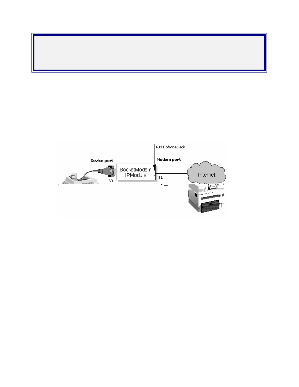
Chapter 6 – Prerequisite Configurations
Chapter 6 – Prerequisite
Configurations
This chapter covers prerequisite tasks, those tasks or configurations that must be completed before you
can set up certain operating scenarios.
Other prerequisite tasks related to specific operating scenarios are described throughout the rest of this
document.
1. MultiConnect IP Communication Interfaces and Conventions
The Serial Interface ports, S0 and S1, correspond to Device Port and Modem Port respectively. This
convention is used throughout this document.
Serial Ports
1. S0 - Device Port - RS-232 port connects to the Host/Serial device.
2. S1 - Modem Port - RJ-11 phone jack port dials the Service Provider, obtains an IP
Address, and provides the IP ability to reach the Host/Serial
devices connected over the device port.
Multi-Tech Systems, Inc. MultiConnect Serial-to-Serial Adapter User Guide (S000354A) 62
Page 63

Chapter 6 – Prerequisite Configurations
2. MultiConnect IP Modes of Operation
The MultiConnect IP can function in two modes:
• Transparent Mode
When the MultiConnect IP is configured to function in the modem operation mode, it
functions as a modem. The Host/Serial device connected on the device port can use the
MultiConnect IP as a modem in transparent mode.
Refer to Chapter 9 for application examples that use Transparent Mode.
• IP Mode
When the MultiConnect IP is configured to function in the IP operation mode, it provides an IP
ability to reach the Hosts/Serial devices connected over the device port. Application such as
SMTP Client, POP3 Client, Telnet Client, Telnet Server, FTP Client, etc. provide this IP ability
to reach the Host/Serial devices.
The figure below depicts the two modes of operation. The modes can be configured through the
Command Line Interface (CLI). By default the MultiConnect IP is set to operate in the IP Mode.
IP Mode
Multi-Tech Systems, Inc. MultiConnect Serial-to-Serial Adapter User Guide (S000354A) 63
Page 64

Chapter 6 – Prerequisite Configurations
3. Physical Link Established over the Modem Port
For any application such as SMTP Client, HTTP Server, POP3 Client, etc. to function, the PPP link
must be opened up on the modem port.
MultiConnect IP implementation provides three mechanisms for establishing the physical link over the
modem port:
• Dialing-trig-mode NONE
• Dialing-trig-mode DTR
• Dialing-trig-mode Command
Choose the method you desire by configuring the physical link through the Command Line Interface
(CLI). Use the following command to configure the Physical Link Establishment Method:
# set serial [serial-interface] modem dialing-trig-mode
<none/dtr/command>
Note: The modem port is set to modem-answering by default.
The command dialing-trig-mode can be used to set the modem port to dial.
Dialing-trig-mode Functionality
None
DTR
Command
Upon boot-up, the modem starts dialing using the set of configured parameters.
Upon boot-up, the modem is set to the answering state by default.
When the DTR goes high on the device port S0, the modem starts to dial on the
modem port.
Link establishment and link termination is at your discretion.
Command to establish the physical link:
# linkup [serial-interface]
Notes:
• This command is valid only for modem port S1 and is invalid for
device port S0.
• This command can be issued only when the dialing-trig-mode
is command.
Examples:
# linkup s1
ERROR: ‘dialing-trig-mode is not set to command.
# linkup s1
OK: ‘CONNECT 14400 LAPM COMPRESSED’
# linkup s1
ERROR: ‘NO DIALTONE’
# linkup s1
ERROR: ‘NO CARRIER’
# linkup s1
ERROR: ‘NO ANSWER’
Command to terminate the physical link:
# hangup [serial-interface]
Notes:
• This command is valid only for modem port S1 and is invalid for
device port S0
• This command can be issued only when the dialing-trig-mode
is command.
Example:
# hangup s1
OK
This hangs up the physical link
Multi-Tech Systems, Inc. MultiConnect Serial-to-Serial Adapter User Guide (S000354A) 64
Page 65

Chapter 7 – Telnet Dialout
Chapter 7 – Telnet Dialout
Introduction
Telnet Dialout Feature
The Telnet feature allows you to access the serial port and establish two-way traffic between the
Telnet/RAW-TCP client and the serial device.
This chapter provides examples of a Telnet client on an IP network (over the modem port) connecting
to a remote serial device. The MultiConnect IP acts as a Terminal Server using the Telnet dialout
feature.
Features
The MultiConnect IP, acting as a Terminal Server, accommodates the following features:
• Authenticates the serial port.
• Monitors and waits for activity on the standard Telnet port (23) or user-defined RAW-Socket.
• Opens the serial port from the command prompt (manual dialout) .
• Opens the serial port directly (auto dialout) using a TCP Client according to the configured
port-number.
• Switches between the command prompt and a dial-out session when the session is in Telnet
mode.
Prerequisites
Mandatory Configuration Settings
The following items must be configured in order to use the dial-out feature:
• Disable the Host Interaction Mode to restrict Telnet-Dial-Out and PPP.
# set serial s0 host-interaction-mode disable
• Enable Auto dial-out globally on all the serial ports.
# set ip telnet auto-dialout enable
• Enable Auto dial-out on the serial port S0.
# set serial s0 auto-dialout enable
• Set the Auto dialout port for the serial port S0.
# set serial s0 auto-dialout-port <port_number>
• Set the Auto dialout protocol for the serial port S0.
# set serial s0 auto-dialout-protocol telnet
An ERROR message displays if any of the above details are not configured or are not valid.
Multi-Tech Systems, Inc. MultiConnect Serial-to-Serial Adapter User Guide (S000354A) 65
Page 66

Optional Configuration Commands
(Return to Scenario 1 - Setup Manual Dialout Notes:)
(Return to Scenario 2 - Auto Dialout Prerequisites
(Return to Scenario 3 - Auto Dial-out in RAW-Mode Notes:
The following commands can be used for optional configurations:
• Enable/Disable the Authentication for Dial-out session
# set login auto-dialout-login <enable/disable>
• Enable/Disable the Switching-between-Dialout & Command Prompt feature
# set ip telnet escape-monitor <enable/disable>
)
)
Chapter 7 – Telnet Dialout
• Set the Escape-Monitor-String to switch between Dialout and Command Prompt sessions.
# set ip telnet escape-string "+++inet"
• Enable/Disable the RAW mode globally for all Dial-out sessions.
# set ip telnet raw-mode <enable/disable>
• Enable/Disable the RAW mode for the serial port S0.
# set serial s0 raw-dialout <enable/disable>
• Set the Baud rate for the serial port S0 to be taken for a Dialout session.
# set serial s0 baud-rate <Baud-rate>
• Set the Flow control for the serial port S0 to be taken for a Dialout session.
# set serial s0 flow-control <rts-cts/none>
• Set the Parity for the serial port S0 to be taken for a Dialout session.
# set serial s0 parity <even/odd/none>
• Set the Data bits for the serial port S0 to be taken for a Dialout session.
# set serial s0 data-bits <7/8>
• Set the Stop bits for the serial port S0 to be taken for a Dialout session.
# set serial s0 stop-bits <1/1.5/2>
• Set the Flow control for the serial port S1 to be taken for a PPP session
# set serial s1 flow-control <rts-cts/none>
• Set the Parity for the serial port S1 to be taken for a PPP session
# set serial s1 parity <even/odd/none>
• Set the Data bits for the serial port S1 to be taken for a PPP session
# set serial s1 data-bits <7/8>
• Set the Stop bits for the serial port S1 to be taken for a PPP session
# set serial s1 stop-bits <1/1.5/2>
Multi-Tech Systems, Inc. MultiConnect Serial-to-Serial Adapter User Guide (S000354A) 66
Page 67

Chapter 7 – Telnet Dialout
Scenario 1 – Manual Dialout
Connect to the MultiConnect IP using a Telnet Client on port 23 (configuration port).
At the command prompt, invoke # dialout serial s0. Once the session is opened successfully, there can
be two-way traffic between the Telnet client and the serial device.
• You can switch from Command Prompt to Dialout session using the restore session command.
• You can switch from Dialout session to Command Prompt using <escape-monitor-string>.
Manual Dialout Feature Through the Command Shell
Multi-Tech Systems, Inc. MultiConnect Serial-to-Serial Adapter User Guide (S000354A) 67
Page 68

MultiConnect IP Manual Dialout Setup Commands
# set serial s0 stop-bits 1
# set serial s0 baud-rate 115200
# set serial s0 data-bits 8
# set serial s0 parity none
# set serial s0 flow-control rts-cts
# set serial s1 stop-bits 1
# set serial s1 baud-rate 115200
# set serial s1 data-bits 8
# set serial s1 parity none
# set serial s1 flow-control rts-cts
# set serial s1 connect-type modem
# set serial s1 modem dial-number 123
# set serial s1 modem dialing-trig-mode none
(Refer to Chapter 6 - Prerequisite Configurations - Physical Link Established over the Modem
Port for more details)
# set ppp ppp0 ipcp-mode client-only
# set ppp ppp0 username "MultiConnect"
# set ppp ppp0 password "MultiConnect"
# save
Enable Authentication for PPP Commands
# set ppp ppp0 authentication enable
# set ppp ppp0 authentication-type <pap/chap/pap-chap>
Chapter 7 – Telnet Dialout
Enable PPP Compression (on both the PPP peers) Commands
# set ppp ppp0 compression enable
# set ppp ppp0 comp-type <both/bsd/deflate>
The Authentication and Compression variations can be used while bringing up the PPP logical
link in all the scenarios (except for Transparent Mode)
Once the physical link is up and PPP interface has acquired an IP address, the MultiConnect IP is
ready to accept a Dial-Out connection.
Use a remote Telnet client and connect to 202.54.39.95 on port 23 (refer to the figure above). On
successful login, at the MultiConnect IP command prompt, invoke
# dial-out serial s0
(The serial port now opens for use.)
Notes:
1. Only one dialout session can be open at a time.
2. The Dialout session is closed when the Telnet session is closed, thereby releasing the serial port.
3. When the Dialout session authentication is enabled as specified in the Optional Configuration
Commands list, the session prompts for the user name and password before opening the session
successfully. (Enabled by default).
4. The serial port is opened with the current serial configuration.
5. When escape-monitor is enabled, care should be taken during file transfer that the escape-
monitor-string is not part of the data.
Multi-Tech Systems, Inc. MultiConnect Serial-to-Serial Adapter User Guide (S000354A) 68
Page 69

Chapter 7 – Telnet Dialout
Scenario 2 – Auto Dialout
In this scenario, the Auto Dialout session in Telnet mode is opened using a Telnet client.
Prerequisites
RAW mode (global and each port) MUST BE DISABLED using the Optional Configuration
Commands.
A Telnet client can open an auto Dialout session by specifying the configured auto-dialout port.
• Once the session is opened successfully, there can be two-way traffic between the Telnet
session and the remote serial device.
Auto Dialout Feature in Telnet Mode
Multi-Tech Systems, Inc. MultiConnect Serial-to-Serial Adapter User Guide (S000354A) 69
Page 70

MultiConnect IP Auto Dialout in Telnet Mode Setup Commands
# set ip telnet auto-dialout enable
# set serial s0 auto-dialout enable
# set serial s0 auto-dialout-port 5000
# set serial s0 auto-dialout-protocol telnet
# set serial s0 baud-rate 115200
# set serial s0 data-bits 8
# set serial s0 parity none
# set serial s0 stop-bits 1
# set serial s0 flow-control rts-cts
# set serial s1 baud-rate 115200
# set serial s1 data-bits 8
# set serial s1 parity none
# set serial s1 stop-bits 1
# set serial s1 flow-control rts-cts
# set serial s1 connect-type modem
# set serial s1 modem dial-number 123
# set serial s1 modem dialing-trig-mode none
(Refer to Chapter 6 – Prerequisite Configurations - Physical Link Established over the
Modem Port for more details)
# set ppp ppp0 ipcp-mode client-or-lan
# set ppp ppp0 authentication enable
# set ppp ppp0 auth-type pap
# set ppp ppp0 username "MultiConnect"
# set ppp ppp0 password "MultiConnect"
# set ppp ppp0 local-ip-addr 202.54.39.95 mask 255.255.255.255
# set ppp ppp0 remote-ip-addr 202.54.39.96 mask 255.255.255.255
# save
Chapter 7 – Telnet Dialout
Once the physical link is up and PPP interface has acquired an IP address the
MultiConnect IP is ready to accept an auto-dialout connection.
Use a Telnet client and connect to 202.54.39.95 on port 5000. This eventually establishes a
Telnet auto-dialout session between the MultiConnect IP and the serial device.
Closing the Telnet client closes the serial port in use.
Notes:
1. Only one dialout session to the same port can be opened at one time.
2. When a dialout session authentication is enabled as specified in the optional commands, the session
prompts for a user name and password before opening the session successfully. (Enabled by
default).
3. The serial port is opened with the current serial configuration.
Multi-Tech Systems, Inc. MultiConnect Serial-to-Serial Adapter User Guide (S000354A) 70
Page 71

Chapter 7 – Telnet Dialout
Scenario 3 – Auto Dialout in RAW Mode
In this scenario, the Auto-Dialout session in RAW mode is opened using a RAW-TCP client.
Prerequisites
RAW mode (Global and each port) MUST BE ENABLED using the Optional Configuration
Commands.
The Auto Dialout session can be opened by a RAW-TCP client by specifying the auto-dialout configured
port. Once the session is opened successfully, there can be two-way traffic between the Telnet session
and the remote serial device.
Important
You cannot switch between the Command Prompt and the Dialout session in RAW-mode.
Auto Dialout Feature in RAW Mode
Multi-Tech Systems, Inc. MultiConnect Serial-to-Serial Adapter User Guide (S000354A) 71
Page 72

Chapter 7 – Telnet Dialout
Commands to Setup Auto Dial-out in RAW-Mode for MultiConnect IP
# set ip telnet auto-dialout enable
# set ip telnet raw-mode enable
# set serial s0 stop-bits 1
# set serial s0 baud-rate 115200
# set serial s0 data-bits 8
# set serial s0 parity none
# set serial s0 flow-control rts-cts
# set serial s0 auto-dialout enable
# set serial s0 raw-dialout enable
# set serial s0 auto-dialout-port 5000
# set serial s0 auto-dialout-protocol telnet
# set serial s1 stop-bits 1
# set serial s1 baud-rate 115200
# set serial s1 data-bits 8
# set serial s1 parity none
# set serial s1 flow-control rts-cts
# set serial s1 connect-type modem
# set serial s1 modem dial-number 123
# set serial s1 modem dialing-trig-mode none
(Refer to Chapter 6 – Prerequisite Configurations - Physical Link Established over the Modem
Port for more details)
# set ppp ppp0 ipcp-mode client-only
# set ppp ppp0 username "MultiConnect"
# set ppp ppp0 password "MultiConnect"
# save
Once the physical link is up and PPP interface has acquired an IP address the
MultiConnect IP is ready to accept Auto dialout connection.
Use a Telnet client and connect to 202.54.39.95 on port 5000 (RAW TCP socket). This eventually
establishes a Telnet auto-dial-out session (In RAWMODE) with the MultiConnect IP, thereby
opening the serial port for use.
Closing the Telnet client closes the serial port in use.
Notes:
1. You cannot open more than one dialout session to the same port.
2. When the Dialout session authentication is enabled as specified in the Optional Configuration
Commands, the session prompts for a user name and password before opening the session
successfully.
3. The serial port is opened with the current serial configuration.
Multi-Tech Systems, Inc. MultiConnect Serial-to-Serial Adapter User Guide (S000354A) 72
Page 73

Chapter 8 – Auto Dial-in Feature
Chapter 8 – Auto Dial-in Feature
Introduction
The auto dial-in feature enables the MultiConnect IP to act as a Telnet client thus facilitating the serial
device to access any Telnet/terminal servers on the IP network (over the built-in modem interface). Once
the session (Serial Client to Server) is opened successfully, it allows two-way traffic between the serial
device and the remote server.
The MultiConnect IP, acting as a Telnet/RAW-TCP client, accommodates the following features when
configured:
• Support to open the session using Telnet client (residing in the MultiConnect IP) in Telnet Mode or
RAW Mode.
• Support to open the session to the specified port from a Serial Command prompt (Manual Dial-in).
• Switching between a Command prompt and a Dial-in session when the session is in Telnet mode.
• Support to open the session to the configured port directly (Serial Auto Dial-in) whenever the serial
port is free.
Prerequisites
Mandatory Configuration Settings
The following items must be configured in order to use the dial-in feature:
• Enable Auto dial-in globally on all the serial ports.
# set serial auto-telnet enable
• Enable Auto dial-in on the serial port S0.
# set serial s0 auto-dial-in enable
• Set the Auto dial-in protocol.
# set serial s0 auto-dialin-protocol telnet
• Set the Auto dial-in Server IP Address.
# set serial s0 auto-dialin-ipaddress <ipaddress>
• Set the port to the one, which the Telnet client will be connected.
# set serial s0 auto-dialin-port <port_number>
An ERROR message will display if any of the above details are not configured or not valid.
Optional Configuration Settings
The following commands can be used for optional configurations:
• Enable/Disable Switching-between-Dial-in and the Command Prompt feature.
# set serial escape-monitor <enable/disable>
• Set the Escape-Monitor-String to switch between Dial-in and Command Prompt sessions.
# set serial escape-string "+++inet"
• Set the Serial Dial-in Trigger mode. It dictates the criterion for establishing a connection.
The options provided are on reception of <char/ dtr/ dtr-char/ none>.
Refer to the command line configuration section for details about this command.
# set serial s0 auto-dialin trig-mode <char/dtr/dtr-char/none>
• Enable/Disable the RAW mode globally for all Auto-Dial-in sessions.
# set ip telnet raw-mode <enable/disable>
• Enable/Disable the RAW mode for Auto-Dial-in session on serial port S0.
# set serial s0 raw-dial-in <enable/disable>
Multi-Tech Systems, Inc. MultiConnect Serial-to-Serial Adapter User Guide (S000354A) 73
Page 74

Chapter 8 – Auto Dial-in Feature
Scenario 1 – Manual Serial Dial-in
Login to the Command prchat-scriptompt from the serial side.
Invoke # telnet <ip-address> <port> at the command prompt. Once the session is opened
successfully, there can be two-way traffic between the serial device and the remote server.
• You can switch from Command Prompt to Dial-in session using the restore session command.
• You can switch from Dial-in session to Command Prompt using <escape-monitor-string>.
Manual Dial-in Feature through the Command Shell
Multi-Tech Systems, Inc. MultiConnect Serial-to-Serial Adapter User Guide (S000354A) 74
Page 75

Chapter 8 – Auto Dial-in Feature
MultiConnect IP Manual Dial-In Setup Commands
# set serial s0 baud-rate 115200
# set serial s0 data-bits 8
# set serial s0 parity none
# set serial s0 stop-bits 1
# set serial s0 flow-control rts-cts
# set serial s1 baud-rate 115200
# set serial s1 data-bits 8
# set serial s1 parity none
# set serial s1 stop-bits 1
# set serial s1 flow-control rts-cts
# set serial s1 connect-type modem
# set serial s1 modem dial-number 123
# set serial s1 modem dialing-trig-mode none
(Refer to the Chapter 6 Prerequisite Configurations - Physical Link Established over the
Modem Port for more details)
# set ppp ppp0 ipcp-mode client-or-lan
# set ppp ppp0 authentication enable
# set ppp ppp0 auth-type pap
# set ppp ppp0 username "MultiConnect"
# set ppp ppp0 password "MultiConnect"
# set ppp ppp0 local-ip-addr 202.54.39.95 mask 255.255.255.255
# set ppp ppp0 remote-ip-addr 202.54.39.96 mask 255.255.255.255
# save
Once the physical link is up and the PPP interface has acquired an IP address, the
MultiConnect IP is ready to use.
Login to the module through the serial port. At the command shell invoke:
# telnet 202.54.39.96 23
The Telnet client on board in the MultiConnect IP establishes a virtual serial tunnel between
the serial device and the Telnet Server.
Notes:
• You cannot open more than one dial-in session.
• The dial-in session is closed when the Telnet session is closed.
• When escape-monitor is enabled, care should be taken during file transfer that the escape-
monitor-string is not part of the data.
Multi-Tech Systems, Inc. MultiConnect Serial-to-Serial Adapter User Guide (S000354A) 75
Page 76

Chapter 8 – Auto Dial-in Feature
Scenario 2 – Serial Auto Dial-in in Telnet Mode
This example shows how to setup a serial auto dial-in session in Telnet mode. The auto dial-in session is
opened by Telnet client embedded in the MultiConnect IP to the configured server on a configured port.
Once the session is opened successfully, there can be two-way traffic between the serial device and the
remote server.
• You can switch from Command Prompt to Dial-in session using the restore session command.
• You can switch from Dial-in session to Command Prompt using <escape-monitor-string>.
Prerequisites
• RAW mode (Global and each port) MUST BE DISABLED using the following command:
Enable/Disable the RAW mode globally for all Auto-Dial-in sessions:
# set ip telnet raw-mode <enable/disable>
Auto Dial-in Feature in Telnet Mode
Multi-Tech Systems, Inc. MultiConnect Serial-to-Serial Adapter User Guide (S000354A) 76
Page 77

Chapter 8 – Auto Dial-in Feature
MultiConnect IP Auto Dial-In Setup in Telnet Mode Commands
# set serial auto-telnet enable
# set serial s0 auto-dialin enable
# set serial s0 auto-dialin trig-mode dtr-char
# set serial s0 auto-dialin-ipaddress 202.54.39.96
# set serial s0 auto-dialin-port 5000
# set serial s0 auto-dialin-protocol telnet
# set serial s0 stop-bits 1
# set serial s0 baud-rate 115200
# set serial s0 data-bits 8
# set serial s0 parity none
# set serial s0 flow-control rts-cts
# set serial s1 stop-bits 1
# set serial s1 baud-rate 115200
# set serial s1 data-bits 8
# set serial s1 parity none
# set serial s1 flow-control rts-cts
# set serial s1 connect-type modem
# set serial s1 modem dial-number 123
# set serial s1 modem dialing-trig-mode none
(Refer to the Chapter 6 Prerequisite Configurations - Physical Link Established over the Modem
Port for more details)
# set ppp ppp0 ipcp-mode client-only
# set ppp ppp0 username "MultiConnect"
# set ppp ppp0 password "MultiConnect"
# save
Once the PPP link is up with an IP address, the auto dial-in session can be probed. When
detecting either a DTR signal or when any character is received from the serial device connected
to the RS-232 serial port of MultiConnect IP, the Telnet client on board in the MultiConnect IP
establishes a Telnet session to 202.54.39.96 on port 23.
The serial tunnel between the serial device and the Telnet Server terminates in one of the
following conditions.
• The connection is broken between the serial device and the serial port of the
MultiConnect IP.
• The Telnet Client on board is terminated.
• The Telnet Server terminates the session.
Notes:
1. You cannot open more than one Dial-in session.
2. The Dial-in session is closed when the configuration session is closed (if opened).
3. When escape-monitor is enabled, care should be taken during file transfer that the escape-
monitor-string is not part of the data.
Multi-Tech Systems, Inc. MultiConnect Serial-to-Serial Adapter User Guide (S000354A) 77
Page 78

Chapter 8 – Auto Dial-in Feature
Scenario 3 – Auto Dial-in Session in RAW Mode
This scenario shows how to configure an auto dial-in session in RAW mode. The auto dial-in session is
opened by Telnet client (embedded in the MultiConnect IP) in RAW-mode to the configured server on a
configured port number. Once the PPP link is up with an IP address, the auto dial-in session can be
probed as in the Auto Dial-In scenario below.
Prerequisites
RAW mode (Global and each port) MUST BE ENABLED using the following command:
Enable/Disable the RAW mode globally for all Auto-Dial-in sessions:
# set ip telnet raw-mode <enable/disable>
Important – You cannot switch between the Command Prompt and a Dial-in session in RAW-
mode. Also, you cannot open more than one Dial-in session.
Auto Dial-in Feature in RAW Mode
MultiConnect IP Auto Dial-In in RAW Mode Setup Commands
# set ip telnet raw-mode enable
# set serial auto-telnet enable
# set serial s0 auto-dialin enable
# set serial s0 raw-dialin enable
# set serial s0 auto-dialin trig-mode dtr-char
# set serial s0 auto-dialin-ipaddress 202.54.39.96
# set serial s0 auto-dialin-port 5000
# set serial s0 auto-dialin-protocol telnet
# set serial s0 stop-bits 1
# set serial s0 baud-rate 115200
# set serial s0 data-bits 8
# set serial s0 parity none
# set serial s0 flow-control rts-cts
# set serial s1 stop-bits 1
# set serial s1 baud-rate 115200
# set serial s1 data-bits 8
# set serial s1 parity none
# set serial s1 flow-control rts-cts
# set serial s1 connect-type modem
# set serial s1 modem dial-number 123
# set serial s1 modem dialing-trig-mode none
(Refer to Chapter 6 - Prerequisite Configurations - Physical Link Established over the Modem Port)
# set ppp ppp0 ipcp-mode client-only
# set ppp ppp0 username "MultiConnect"
# set ppp ppp0 password "MultiConnect"
# save
Multi-Tech Systems, Inc. MultiConnect Serial-to-Serial Adapter User Guide (S000354A) 78
Page 79

Chapter 8 – Auto Dial-in Feature
Scenario 4 – Serial Tunneling Mode
The scenario shows a serial tunnel established between two serial devices (Serial Device-1, Serial
Device-2) using two MultiConnect IP modules, which are located apart geographically. Once the PPP link
is up with an IP address on S1, the dial-in session can occur.
The Serial Devices then communicate to each other across the MultiConnect IP modules.
Serial Tunneling
Multi-Tech Systems, Inc. MultiConnect Serial-to-Serial Adapter User Guide (S000354A) 79
Page 80

Chapter 8 – Auto Dial-in Feature
Commands for Serial Tunneling Setup Using Two MultiConnect IP Modules
Commands for MultiConnect IP Module 1 (Configure for Serial Auto Dial-in)
# set ip telnet raw-mode enable
# set serial auto-telnet enable
# set serial s0 auto-dialin enable
# set serial s0 raw-dialin enable
# set serial s0 auto-dialin trig-mode dtr-char
# set serial s0 auto-dialin-ipaddress 202.54.39.96
# set serial s0 auto-dialin-port 5000
# set serial s0 auto-dialin-protocol telnet
# set serial s0 stop-bits 1
# set serial s0 baud-rate 115200
# set serial s0 data-bits 8
# set serial s0 parity none
# set serial s0 flow-control rts-cts
# set serial s1 stop-bits 1
# set serial s1 baud-rate 115200
# set serial s1 data-bits 8
# set serial s1 parity none
# set serial s1 flow-control rts-cts
# set serial s1 connect-type modem
# set serial s1 modem dial-number 123
# set serial s1 modem dialing-trig-mode none
(Refer to Chapter 6 – Prerequisite Configurations - Physical Link Established over the Modem Port)
# set ppp ppp0 enable
# set ppp ppp0 ipcp-mode client-or-lan
# set ppp ppp0 authentication enable
# set ppp ppp0 auth-type pap
# set ppp ppp0 username "MultiConnect"
# set ppp ppp0 password "MultiConnect"
# set ppp ppp0 local-ip-addr 202.54.39.95 mask 255.255.255.255
# set ppp ppp0 remote-ip-addr 202.54.39.96 mask 255.255.255.255
# save
Commands for MultiConnect IP Module 2 (Configure for Telnet Auto Dial-out)
# set ip telnet auto-dialout enable
# set ip telnet raw-mode enable
# set serial s0 auto-dialout enable
# set serial s0 auto-dialout-port 5000
# set serial s0 auto-dialout-protocol telnet
# set serial s0 raw-dialout enable
# set serial s0 baud-rate 115200
# set serial s0 data-bits 8
# set serial s0 parity none
# set serial s0 stop-bits 1
# set serial s0 flow-control rts-cts
# set serial s1 baud-rate 115200
# set serial s1 data-bits 8
# set serial s1 parity none
# set serial s1 stop-bits 1
# set serial s1 flow-control rts-cts
# set serial s1 connect-type modem
# set serial s1 modem dialing-trig-mode command
(The default mode is answering. This command changes the mode to answering.)
# set ppp ppp0 enable
# set ppp ppp0 ipcp-mode client-or-lan
# set ppp ppp0 authentication enable
# set ppp ppp0 auth-type pap
# set ppp ppp0 username "MultiConnect"
# set ppp ppp0 password "MultiConnect"
# set ppp ppp0 local-ip-addr 202.54.39.96 mask 255.255.255.255
# set ppp ppp0 remote-ip-addr 202.54.39.95 mask 255.255.255.255
# save
Multi-Tech Systems, Inc. MultiConnect Serial-to-Serial Adapter User Guide (S000354A) 80
Page 81

Chapter 9 – Modem (Transparent) Mode
Chapter 9 – Modem (Transparent)
Mode
Introduction
In the modem mode (also called transparent mode), raw data is communicated between serial ports 1
and 2. This means that:
• Data received on serial port S0 is transmitted on serial port S1
• Data received on serial port S1 is transmitted on serial port S0
Transparent mode can be used in the following applications:
• The MultiConnect IP is used as a Modem
• Serial Tunneling
Prerequisites
• Transparent Mode must be enabled
# set operation-mode modem
• Host Interaction mode must be disabled
# set serial s0 host-interaction-mode disable
• Enable Switching-between Data mode and Command mode
# set serial s0 escape-monitor enable
• Set the Escape-Monitor-String to switch between Data mode and Command mode
# set serial s0 escape-string "+++inets0"
Multi-Tech Systems, Inc. MultiConnect Serial-to-Serial Adapter User Guide (S000354A) 81
Page 82

Chapter 9 – Modem (Transparent) Mode
Scenario 1 – MultiConnect IP as a Modem
In this scenario, once the physical link is up on the built-in modem interface; i.e., by dialing or answering,
Multi-Tech Systems, Inc. MultiConnect Serial-to-Serial Adapter User Guide (S000354A) 82
Page 83

Chapter 9 – Modem (Transparent) Mode
Scenario 2 – Serial Tunneling in Transparent
Mode
In this scenario, two MultiConnect IP modules in transparent mode aid in the communication between two
serial devices that are connected to the RS-232 interface (S0) of the MultiConnect IP modules. Serial
tunneling is achieved in the transparent mode where raw data is communicated.
Serial Tunneling in Transparent Mode
Multi-Tech Systems, Inc. MultiConnect Serial-to-Serial Adapter User Guide (S000354A) 83
Page 84

Commands for MultiConnect IP - 1 (Dialing End)
# set operation-mode modem
# set serial s0 escape-monitor enable
# set serial s0 escape-string "+++inets0"
# set serial s0 stop-bits 1
# set serial s0 baud-rate 115200
# set serial s0 data-bits 8
# set serial s0 parity none
# set serial s0 flow-control rts-cts
# set serial s1 stop-bits 1
# set serial s1 baud-rate 115200
# set serial s1 data-bits 8
# set serial s1 parity none
# set serial s1 flow-control rts-cts
# save
Commands for MultiConnect IP - 2 (Answering End)
# set operation-mode modem
# set serial s0 escape-monitor enable
# set serial s0 escape-string "+++inets0"
# set serial s0 baud-rate 115200
# set serial s0 data-bits 8
# set serial s0 parity none
# set serial s0 stop-bits 1
# set serial s0 flow-control rts-cts
# set serial s1 baud-rate 115200
# set serial s1 data-bits 8
# set serial s1 parity none
# set serial s1 stop-bits 1
# set serial s1 flow-control rts-cts
# save
Chapter 9 – Modem (Transparent) Mode
Steps for Establishing a Physical Link in Transparent Mode
1. Complete the configuration listed above.
2. At the dialing end, invoke the following commands:
atz
at&f
atdt <dial no>
3. Once the physical connection is up, the data channel between the two MultiConnect IP
modules is established.
Note: Only raw data is forwarded between the MultiConnect IP modules, and no data
integrity check is provided.
4. Type +++ followed by ATH0 to hangup the modem.
Notes
• You can switch from Data mode to Command mode using the escape-monitor-string
command. The Command mode transfers control to the Command Shell of MultiConnect IP.
• You can switch from Command mode to Data mode using the restore session command.
• The data session is dropped if the physical link goes down.
Multi-Tech Systems, Inc. MultiConnect Serial-to-Serial Adapter User Guide (S000354A) 84
Page 85

Chapter 10 − Modem Mode AT Commands, S-Registers, and Result Codes
Chapter 10 – Modem Mode AT
Commands, S-Registers, Result Codes
This chapter covers the V.22bis, V.32, V.34, and V.92 commands, S-Registers, and Result Codes. The
AT commands are used to control the operation of your modem. They are called AT commands because
the characters AT must precede each command to get the ATtention of the modem.
AT commands can be issued only when the modem is in command mode or online command mode. The
modem is in command mode whenever it is not connected to another modem. The modem is in data
mode whenever it is connected to another modem and ready to exchange data. Online command mode is
a temporary state in which you can issue commands to the modem while connected to another modem.
To put the modem into online command mode from data mode, you must issue an escape sequence
(+++) followed immediately by the AT characters and the command, e.g., +++ to hang up the modem. To
return to data mode from online command mode, you must issue the command ATO.
To send AT commands to the modem you must use a communications program, such as the
HyperTerminal applet in Windows, or some other available terminal program. You can issue commands
to the modem either directly, by typing them in the terminal window of the communications program, or
indirectly, by configuring the operating system or communications program to send the commands
automatically. Fortunately, communications programs make daily operation of modems effortless by
hiding the commands from the user. Most users, therefore, need to use AT commands only when
reconfiguring the modem, e.g., to turn autoanswer on or off.
The format for entering an AT command is ATXn, where X is the command and n is the specific value for
the command, sometimes called the command parameter. The value is always a number. If the value is
zero, you can omit it from the command; thus, AT&B is equivalent to AT&B0. Most commands have a
default value, which is the value that is set at the factory.
You must press ENTER (depending on the terminal program it could be some other key) to send the
command to the modem. Any time the modem receives a command, it sends a response known as a
result code. The most common result codes are OK, ERROR, and the CONNECT messages that the
modem sends to the computer when it is connecting to another modem. For a table of valid result codes,
see “Result Codes” at the end of this chapter.
You can issue several commands in one line, in what is called a command string. The command string
begins with AT and ends when you press ENTER. Spaces to separate the commands are optional; the
command interpreter ignores them. The most familiar command string is the initialization string, which is
used to configure the modem when it is turned on or reset, or when your communications software calls
another modem.
Escape Code Sequence +++
When the modem has established a connection and has entered online data mode, it is possible to break
into the data transmission in order to issue further commands to the modem in an online command mode.
This is achieved by the DTE sending to the modem a sequence of three ASCII characters specified by SRegister S2. The default character is '+'. The maximum time allowed between receipt of the last character
of the three-escape character sequence (+++) from the DTE and sending of the OK result code to the
DTE is controlled by the S12 register.
Command Organization
The commands in this chapter are listed in the following order:
• First, the commands that begin with letters are listed in alphabetical order
• Then the commands that begin with symbols are listed in this order &, \, –, %, +, #, +++
• Fast Connect Commands
• V.92 Commands
Multi-Tech Systems, Inc. MultiConnect Serial-to-Serial Adapter User Guide (S000354A) 85
Page 86

Chapter 10 − Modem Mode AT Commands, S-Registers, and Result Codes
Command Types
The following list should help if you are looking for a particular type of command. This list categorizes AT
Commands by function.
Generic Modem Control Commands
Z
+VCID
+VRID
\N
I
+GMI
+GMM
+GMR
+GCAP
+GCI
&F
&T
&Y
&W
&Zn=x
Soft Reset and Restore Profile
Caller ID
Report Retrieved Caller ID
Operating Mode – Error Control
Identification
Request Manufacturer Identification
Request Model Identification
Request Revision Identification
Request Complete Capabilities List
Country of Installation
Restore Factory Configuration (Profile)
Local Analog Loopback Test
Designate a Default Profile
Store Current Configuration
Store Telephone Number
DTE–Modem Interface Commands
E
Q
V
W
X
&C
&D
&K
&R
&S
+IPR
+IFC
+ILRR
Command Echo
Quiet Result Code Control
Result Code Form
Connect Message Control
Extended Result Codes
RLSD (DCD) Option
Data Terminal Ready (DTR) Option
Flow Control
RTS/CTS Option
DSR Override
Fixed DTE Rate
DTE-Modem Local Flow Control
DTE-Modem Local Rate Reporting
Call Control Commands
D
T
P
A
H
O
L
M
&G
&P
&V
&V1
\V
%L
%Q
-STE
Dial
Set Tone Dial Default
Set Pulse Dial Default
Answer
Disconnect (Hang-up)
Return to Online Data Mode
Speaker Volume
Speaker Control
Select Guard Tone
Select Pulse Dial Make/Break Ratio
Display Current Configuration and Stored Profiles
Display Last Connection Statistics
Single Line Connect Message Enable
Report Line Signal Level
Report Line Signal Quality
Set Telephony Extension
Multi-Tech Systems, Inc. MultiConnect Serial-to-Serial Adapter User Guide (S000354A) 86
Page 87

Chapter 10 − Modem Mode AT Commands, S-Registers, and Result Codes
Call Control Commands
+MS
+MR
%E
%U
B
Modulation Selection
Modulation Reporting Control
Enable/Disable Line Quality Monitor and Auto-Retrain
Select µ-Law or A-Law Codec Type
Communication Standard – CCITT or Bell
Error Control Commands
+ES
+EB
+ESR
+EFCS
+ER
+ER <type>
+ETBM
\B
\K
-K
Error Control
Break Handling in Error Control Operation
Selective Repeat
32-bit Frame Check Sequence
Error Control Reporting
Report the Current Error Control
Call Termination Buffer Management
Transmit Break to Remote
Break Control
MNP Extended Services
Data Compression Commands
+DS
+DR
%C
Data Compression
Data Compression Reporting
Enable/Disable Data Compression
V.8/V.8bis Commands
+A8E
+A8I
V.8 and V.8bis Operation Controls
CI Signal Indication
Multi-Tech Systems, Inc. MultiConnect Serial-to-Serial Adapter User Guide (S000354A) 87
Page 88

Chapter 10 − Modem Mode AT Commands, S-Registers, and Result Codes
Command Detail
Command: AT Attention Code
Values: n/a
Description: The attention code precedes all command lines except for escape sequences.
Command: ENTER Key
Values: n/a
Description: Press the E
Command: A Answer
Values: n/a
Description: Answer call before final ring. The modem will go off-hook and attempt to answer an
incoming call if correct conditions are met. Upon successful completion of answer
handshake, the modem will go on-line in answer mode. This command may be
affected by the state of Line Current Sense, if enabled. (Most countries do not
require Line Current Sense.) Operation is also dependent upon country-specific
requirements.
The modem will enter the connect state after exchanging carrier with the remote
modem.
If no carrier is detected within a period specified in register S7, the modem hangs
up.
Any character entered during the connect sequence will abort the connection
attempt.
Command: A/ Repeat Last Command
Values: n/a
Description: Repeats the last command string. Do not precede this command with AT. Do not press
Enter to execute.
Command: Bn Communication Standard Setting – ITU-T or Bell
Values: n = 0, 1
Default: 0
Description: When the modem is configured to allow either option, the modem will select Bell or ITU-T
modulation for a line speed connection of 300 or 1200 bps. Any other line speed will use an
ITU-T modulation standard. The parameter value, if valid, is written to S27 bit 6.
B0 Selects ITU-T operation at 300 or 1200 bps during Call Establishment and a
B1 Selects Bell operation at 300 or 1200 bps during Call Establishment and a subsequent
B2 Selects V.23 half-duplex operation at 1200 bps during Call Establishment and a
B3 Disables V.23 half-duplex operation. (V.22bis only).
Command: Ds Dial
Values: s = dial string (phone number and dial modifiers)
Default: none
Description: This command directs the modem to go on-line, dial according to the string entered and
attempt to establish a connection. If no dial string is supplied, the modem will go on-line and
attempt the handshake in originate mode.
Note: If the ATD command is issued before the S1 register has cleared, the modem will
respond with the NO CARRIER result code.
Dial Modifiers
NTER (RETURN) key to execute most commands.
subsequent connection.
connection.
subsequent connection. (V.22bis only).
DTMF digits 0 to 9.
0-9
* The 'star' digit (tone dialing only).
# The 'gate' digit (tone dialing only).
A-D Some countries may prohibit sending of these digits during dialing (tone dialing
only)
L Redial last number. (Must be placed immediately after ATD.)
Multi-Tech Systems, Inc. MultiConnect Serial-to-Serial Adapter User Guide (S000354A) 88
Page 89

Chapter 10 − Modem Mode AT Commands, S-Registers, and Result Codes
P Select pulse dialing: pulse dial the numbers that follow until a "T" is encountered.
Affects current and subsequent dialing. Some countries prevent changing dialing
modes after the first digit is dialed.
T Select tone dialing: tone dial the numbers that follow until a "P" is encountered.
Affects current and subsequent dialing. Some countries prevent changing dialing
modes after the first digit is dialed.
R This command will be accepted, but not acted on.
S=n Dial the number stored in the directory (n = 0 to 3). (See &Z.) (S=n is not
available with V.22bis).
! Flash: the modem will go on-hook for a time defined by the value of S29. Country
requirements may limit the time imposed.
W Wait for dial tone: the modem will wait for dial tone before dialing the digits
following "W". If dial tone is not detected within the time specified by S7 (US) or
S6 (W-class), the modem will abort the rest of the sequence, return on-hook, and
generate an error message.
@ Wait for silence: the modem will wait for at least 5 seconds of silence in the call
progress frequency band before continuing with the next dial string parameter. If
the modem does not detect these 5 seconds of silence before the expiration of
the call abort timer (S7), the modem will terminate the call attempt with a NO
ANSWER message. If busy detection is enabled, the modem may terminate the
call with the BUSY result code. If answer tone arrives during execution of this
parameter, the modem handshakes.
& Wait for credit card dialing tone before continuing with the dial string. If the tone
is not detected within the time specified by S7 (US models) or S6 (W-class
models), the modem will abort the rest of the sequence, return on-hook, and
generate an error message.
, Dial pause: the modem will pause for a time specified by S8 before dialing the
digits following ",".
; Return to command state. Added to the end of a dial string, this causes the
modem to return to the command state after it processes the portion of the dial
string preceding the ";". This allows the user to issue additional AT commands
while remaining off-hook. The additional AT commands may be placed in the
original command line following the ";" and/or may be entered on subsequent
command lines. The modem will enter call progress only after an additional dial
command is issued without the ";" terminator. Use "H" to abort the dial in
progress, and go back on-hook.
^ Toggles calling tone enable/disable: applicable to current dial attempt only.
( ) Ignored: may be used to format the dial string.
- Ignored: may be used to format the dial string.
<space> Ignored: may be used to format the dial string.
<i> Invalid character: will be ignored.
> If enabled by country specific parameter, the modem will generate a grounding
pulse on the EARTH relay output.
Command: En Echo Command
Values: n = 0 or 1
Default: 1
Description: The modem enables or disables the echo of characters to the DTE. The valid
parameter value is written to S14 bit 1.
E0 Disables echo command.
E1 Enables echo command.
Command:
Values: n = 0 or 1
Default: None
Description:
H0 The modem will release the line if the modem is currently online and will terminate any
H1 If on-hook, the modem will go off-hook and enter command mode. For US models, the
Hn Disconnect (Hang Up)
This command may not be available in some countries due to PTT restrictions.
test (AT&T) that is in progress. Country specific, modulation specific, and error
correction protocol specific (S38) processing is handled outside of the H0 command.
modem will remain off-hook. For global models, the modem will return on-hook after a
period of time determined by S7.
Multi-Tech Systems, Inc. MultiConnect Serial-to-Serial Adapter User Guide (S000354A) 89
Page 90

Chapter 10 − Modem Mode AT Commands, S-Registers, and Result Codes
Command:
In Identification (for V.22bis)
This command causes the modem to reports the requested result according to the
command parameter.
Values: n = 0–7
Default: None
I0 Reports product code, e.g., “2400”.
I1 Reports the least significant byte of the stored checksum in decimal. Reports
255 if the prestored checksum value is FFh.
I2 Check ROM and verify the checksum, displaying OK or ERROR.
I3 Reports ROM Code Revision-Modulation (e.g., 2109-V90). Revision,
Modulation, and Model.
I4 Reports OEM defined identifier string.
I5 Reports Country Code parameter (see +GCI).
I6 Reports modem data pump and internal code revision.
I7 Reports OK.
Command:
Values: n = 0, 1, 2, or 3
Default: 2
Description: This command sets the speaker volume cont rol. The parameter value, if valid, is written to
L0 Select low volume.
L1 Select low volume.
L2 Select medium volume.
L3 Select high volume.
Command:
Values: n = 0, 1, 2, or 3
Default: 1
Description: This command selects when the speaker will be on or off. The parameter value, if valid, is
M0 Speaker always off.
M1 Speaker on until carrier signal detected.
M2 Speaker always on when modem is off-hook.
M3 Speaker on until carrier is detected, except while dialing, but on during answering.
Command:
Values: 0, 4, 5
Default: None
Description:
O0 Enters on-line data mode without a retrain. Handling is determined by the Call
O1 Enters on-line data mode with a retrain before returning to on-line data mode.
Fast retrain without speed change (used for diagnostic purpose only).
Renegotiate rate without speed change (used for diagnostic purpose only. (Not in
O2 Fast retrain without speed change (used for diagnostic purpose only).
O3 Renegotiate rate without speed change (used for diagnostic purpose only.
O4 Renegotiate rate down one speed (used for diagnostic purpose only). (Not in V.22bis)
O5 Renegotiate rate up one speed (used for diagnostic purpose only). (Not in V.22bis)
Ln Monitor Speaker Volume
S22 bits 0 and 1.
Mn Monitor Speaker Mode
written to S22 bits 2 and 3.
On Return to Online Data Mode
This command determines how the modem will enter the on-line data mode. If in the on-line
command mode, the modem enters the on-line data mode with or without a retrain. If in the
off-line command mode (no connection), the modem reports ERROR.
Establishment task. Generally, if a connection exists, this command connects the DTE
back to the remote modem after an escape (+++).
V.22bis)
Multi-Tech Systems, Inc. MultiConnect Serial-to-Serial Adapter User Guide (S000354A) 90
Page 91

Chapter 10 − Modem Mode AT Commands, S-Registers, and Result Codes
Command:
Values: P, T
Default: T
Description:
Command:
Values: n = 0 or 1
Default: 0
P Set Pulse Dial Default
This command forces pulse dialing until the next T dial modifier of T command is received. As
soon as a dial command is executed which specifies the dialing mode for that particular call
(e.g., ATDT…), this command is overridden so that all future dialing will be tone dialed. (See
T command). This command may not be permitted in some countries.
Qn Quiet Result Codes Enable/Disable
Description: The command enables or disables the sending of result codes to the DTE. The
parameter value, if valid, is written to S14 bit 2.
Q0 Enables result codes to the DTE.
Q1 Disables result codes to the DTE.
Command: T Set Tone Dial Default
Values: P, T
Default: T
Description:
Command:
Values: n = 0 or 1
Default: 1
Description:
This command forces DTMF dialing until the next P dial modifier or P command is received.
Vn Result Code Form (Not available in V.22bis)
This command selects the sending of short-form or long-form result codes to the DTE.
The modem will set an S-Parameter bit to indicate that all subsequent dialing should be
conducted in tone mode. The
not be permitted in some countries.
DP command will override this command. This command may
V0 Enables short-form (terse) result codes. Line feed is not issued before a short-
form result code.
V1 Enables long-form (verbose) result codes.
Command:
Values: n = 0, 1, or 2
Default: 0
Description:
The W parameter value, if valid, is written to S31 bits 2 and 3.
W0 Upon connection, the modem reports only the DTE speed (e.g., CONNECT 19200).
W1 Upon connection, the modem reports the modulation, line speed, the error correction
W2 Upon connection, the modem reports the DCE speed (e.g., CONNECT 14400).
Subsequent responses are disabled.
Wn Connect Message Control
This command, in conjunction with S95 bits 0, 2, 3, and 5 (bits 2, 3, and 5 can be written
directly by the host or by the +MR, +ER, and +DR commands, respectively), control the
format of CONNECT messages. The actual result code messages reported reflect the W
command setting and the S95 bit settings. (Also see +MR, +ER, and +DR commands.)
Subsequent responses are disabled.
protocol, and the DTE speed, respectively. Subsequent responses are disabled.
Multi-Tech Systems, Inc. MultiConnect Serial-to-Serial Adapter User Guide (S000354A) 91
Page 92

Chapter 10 − Modem Mode AT Commands, S-Registers, and Result Codes
Command: Xn Extended Result Codes and Call Progress Information
Values: n = 0–4
Default: 4
Description: This command selects the subset of the result code messages used by the modem to inform
the DTE of the results of commands. See Extended Results Code Chart in the Results Code
section of this chapter.
X0 Disables reporting of busy tones unless forced otherwise by country requirements; send
only OK, CONNECT, RING, NO CARRIER, ERROR, and NO ANSWER result codes.
Blind dialing is enabled/disabled by country parameters. If busy tone detection is
enforced and busy tone is detected, NO CARRIER will be reported. If dial tone detection
is enforced or selected and dial tone is not detected, NO CARRIER will be reported
instead of NO DIAL TONE. The value 000b is written to S22 bits 6, 5, and 4,
respectively.
X1 Disables reporting of busy tones unless forced otherwise by country requirements; send
only OK, CONNECT, RING, NO CARRIER, ERROR, NO ANSWER, and CONNECT
XXXX (XXXX = rate). Blind dialing enabled/disabled by country parameters. If busy tone
detection is enforced and busy tone is detected, NO CARRIER will be reported instead
of BUSY. If dial tone detection is enforced or selected and dial tone is not detected, NO
CARRIER will be reported instead of NO DIAL TONE. The value 100b is written to S22
bits 6, 5, and 4, respectively.
X2 Disables reporting of busy tones unless forced otherwise by country requirements; send
only OK, CONNECT, RING, NO CARRIER, ERROR, NO DIAL TONE, NO ANSWER,
and CONNECT XXXX. If busy tone detection is enforced and busy tone is detected, NO
CARRIER will be reported instead of BUSY. If dial tone detection is enforced or
selected and dial tone is not detected, NO DIAL TONE will be reported instead of NO
CARRIER. The value 101b is written to S22 bits 6, 5, and 4, respectively.
X3 Enables reporting of busy tones; send only OK, CONNECT, RING, NO CARRIER,
ERROR, NO ANSWER, and CONNECT XXXX. Blind dialing is enabled/disabled by
country parameters. If dial tone detection is enforced and dial tone is not detected, NO
CARRIER will be reported. The value 110b is written to S22 bits 6, 5, and 4,
respectively.
X4 Enables reporting of busy tones; send all messages. The value 111b is written to S22
bits 6, 5, and 4, respectively. (Default.)
Command:
Values: n = 0 or 1
Default: None
Description: Causes the modem to perform a soft reset and restore (recall) of the factory default
Z1 Soft reset and restore stored profile 1. (Not available in V.22bis except for compatibility).
Command:
Values: n = 0 or 1
Default: 1
Description:
&C0 RLSD remains ON at all times.
&C1 RLSD follows the state of the carrier.
Command:
Values: n = 0, 1, 2, or 3
Default: 2
Description: This command interprets the ON to OFF transition of the DTR signal from the DTE in
&D1 - DTR drop is interpreted as if the escape sequence had been entered. The modem
&D2 - DTR drop causes the modem to hang up. Auto-answer is inhibited. (Default.)
&D3 - DTR drop causes the modem to perform a soft reset as if the Z command were
Zn Soft Reset and Restore Profile
configuration profile.
Z0 Soft reset and restore stored profile 0.
&Cn RLSD (DCD) Option
The modem controls the RLSD output in accordance with the parameter supplied. The
parameter value, if valid, is written to S21 bit 5.
&Dn Data Terminal Ready (DTR) Option
accordance with the parameter supplied. The parameter value, if valid, is written to S21 bits
3 and 4. Also, see 25.
&D0 - Allows operation with DTEs which do not provide DTR.
returns to the command state without disconnecting.
received. The &Y setting determines which profile is loaded.
Multi-Tech Systems, Inc. MultiConnect Serial-to-Serial Adapter User Guide (S000354A) 92
Page 93

Chapter 10 − Modem Mode AT Commands, S-Registers, and Result Codes
Command:
Values: n = 0
Default: None
Description: The modem loads the factory default configuration (profile). The factory defaults are
&F0 Restore factory configuration 0.
&F1 Restore factory configuration 1. (Not available in V.22bis).
Command:
Values: n = 0, 1, or 2
Default: 0
Description:
&G0 Disables guard tone.
&G1 Disables guard tone.
&G2 Set guard tone to 1800 Hz.
Command:
Values: n = 0, 3, 4, 5
Defaults: 3
Description: This command defines the DTE/DCE (terminal/modem) flow control mechanism. The
&K0 Disables flow control.
&K3 Enables RTS/ CTS flow control.
&K4 Enables XON/XOFF flow control.
&K5 Enables transparent XON/XOFF flow control.
Command:
Values: n = 0, 1, 2, 3
Default: Country-Dependent
&Fn Restore Factory Configuration (Profile)
identified for each command and in the S-Register descriptions. A configuration (profile)
consists of a subset of S-Registers.
&Gn Select Guard Tone
This command causes the modem to generate the guard tone selected by this command
(DPSK modulation modes only). This command may not be permitted in some countries.
&Kn Flow Control
parameter value, if valid, is written to S39 bits 0, 1, and 2.
&Pn Select Pulse Dial Make/Break Ratio
Description: This command determines the make/break ratio used during pulse dialing. It is only
effective if the appropriate bit to enable this command is set through the country
profile. The default is country-dependent. The parameter value, if valid, is written to
S28 bits 3 and 4.
&P0 Selects 39%-61% make/break ratio at 10 pulses per second. (Default in V.22bis))
&P1 Selects 33%-67% make/break ratio at 10 pulses per second.
&P2 Selects 39%-61% make/break ratio at 20 pulses per second.
&P3 Selects 33%-67% make/break ratio at 20 pulses per second.
Command: &R RTS/CTS Option
Values: 0, 1
Default: None
Description: This selects how the modem controls CTS. The CTS operation is modified if hardware flow
control is selected (see &K command). The parameter value, if valid, is written to S21 bit 2.
&R0 In sync mode, CTS tracks the state of RTS; the RTS-to-CTS delay is defined by S26.
In async mode, CTS is normally ON and will turn OFF only if required by flow control.
&R1 In sync mode, CTS is always ON (RTS transitions are ignored), tracks the state of
RTS; In async mode, CTS is normally ON and will turn OFF only if required by flow
control.
Command:
Values: n = 0, 1
Default: 0
Description:
S21 bit 6.
&S0 DSR is always high (ON).
&S1 DSR goes high (ON) only during a connection.
&Sn DSR Override (&S has no functionality in V.22bis)
Selects ho w the modem will control DSR. The parameter value, if valid, is written to
Multi-Tech Systems, Inc. MultiConnect Serial-to-Serial Adapter User Guide (S000354A) 93
Page 94

Chapter 10 − Modem Mode AT Commands, S-Registers, and Result Codes
Command:
Values: n = 0, 1,
Default: None
Description: The modem can perform the local analog loopback test if
&T0 Stops any test in progress. Clears S16.
&T1 Starts a local analog loopback, V.54 Loop 3, test. If a connection exists when this
Command:
Values: n/a
Description: Displays the active configuration and the stored user profiles.
Example:
&Tn Local Analog Loopback Test
run only when the modem is operating in asynchronous mode with non-error-correction
(normal). To terminate a test in progress, the escape sequence (
command is issued, the modem hangs up. When the test starts, a
message is displayed.
&V Display Current Configuration and Stored Profiles
Note: Only the Active Profile is available in V.22bis.
ACTIVE PROFILE:
B1 E1 L1 M1 N0 QO T V1 W0 X4 Y0 &C1 &D2 &G0 &J0 &K3 &Q5 &R1 &S0 &T5 &X0
S00:000 S01:000 S02:043 S03:013 S04:010 S05:008 S06:002 S07:050 S08:002 S09:006
S10:014 S11:095 S12:050 S18:000 S25:005 S26:001 S36:007 S38:020 S46:138
S48:007 S95:000
STORED PROFILE 0:
B1 E1 L1 M1 N0 QO T V1 W0 X4 Y0 &C1 &D2 &G0 &J0 &K3 &Q5 &R1 &S0 &T5 &X0
S00:000 S02:043 S06:002 S07:050 S08:002 S09:006 S10:014 S11:095 S12:050 S18:000
S36:007 S40:104 S41:195 S46:138 S95:000
STORED PROFILE 1:
B1 E1 L1 M1 N0 QO T V1 W0 X4 Y0 &C1 &D2 &G0 &J0 &K3 &Q5 &R1 &S0 &T5 &X0
S00:000 S02:043 S06:002 S07:050 S08:002 S09:006 S10:014 S11:095 S12:050 S18:000
S36:007 S40:168 S41:195 S46:138 S95:000
&T1 is selected. The test can be
+++) must be entered first.
CONNECT
Multi-Tech Systems, Inc. MultiConnect Serial-to-Serial Adapter User Guide (S000354A) 94
Page 95

Chapter 10 − Modem Mode AT Commands, S-Registers, and Result Codes
Command:
Values: n = 1
Default: 1
Description:
Command:
Values: n = 0, 1
Default: 0
Description:
&W0 Store the current configuration as profile 0.
Command: &Y Designate a Default Reset Profile (No available in V.22bis)
Values: 0, 1
Default: None
Description:
&Y0 The modem will use profile 0.
&V1 Display Last Connection Statistics (&V1 has no functionalit y in V.22bis)
Displays the last connections in the following format (shown with typical results):
TERMINATION REASON.......... LOCAL REQUEST
LAST TX rate................ 26400 BPS
HIGHEST TX rate............. 26400 BPS
LAST RX rate................ 49333 BPS
HIGHEST RX rate………… 49333
BPS PROTOCOL………….. LAPM
PROTOCOL………………… LAPM
COMPRESSION................. V42Bis
Line QUALITY................ 038
Rx LEVEL.................... 015
Highest Rx State............ 67
Highest TX State............ 67
EQM Sum..................... 00B4
Min Distance................ 0000
RBS Pattern................. 00
Rate Drop................... 00
Digital Loss................ 2000
Local Rtrn Count............ 00
Remote Rtrn Count........... 00
Flex 9481814347C4
RBS Pattern: Shows which bits are being robbed in the least significant 6 bytes, e.g., 03
indicates 2 robbed bits in bit positions 0 and 1.
Digital Loss: Shows if a pad is encountered and if so, what is the digital loss. 2000 means 0dB.
Flex: Shows V.8bis information as follows:
First byte: Octet 13 (second byte of manufacturer id, 94 = K56flex)
Second byte: Octet 14 (Licensee code: 81 = Conexant)
Third byte: Octet 15 (manufacturer's product capabilities)
Fourth byte: Octet 16 (K56flex version number)
Fifth byte: Octet 17 (Conexant pump code version number)
Sixth byte: Octet 18 (x-law and controller version number)
Bit 6 Forced/Not forced A-Law/
0 = Forced A-Law/
1 = Not forced A-Law/
Bit 5 Select A-Law or
0 = Select A-Law
1 = Select
Bit 4:0 Controller version
&Wn Store Current Configuration Settings (Not available in V.22bis)
Saves the current (active) configuration (profile), including S-Parameters, in one of the two
user profiles in NVRAM as denoted by the parameter value. The current configuration is
comprised of a list of storable parameters illustrated in the
restored to the active configuration upon receiving a
command).
&W1 Store the current configuration as profile 1.
This command selects which user profile will be used after a hard reset.
&Y1 The modem will use profile 1.
µ-Law
µ-Law
µ-Law
µ-Law
µ-Law
&V command. These settings are
Z command or at power up (see &Y
Multi-Tech Systems, Inc. MultiConnect Serial-to-Serial Adapter User Guide (S000354A) 95
Page 96

Chapter 10 − Modem Mode AT Commands, S-Registers, and Result Codes
Command:
Values: y = 0–3
x = Dialing command
Default: None
Description:
Command:
Values: n = 0–9 in 100 ms units
Default: 3
Description: In non-error correction mode, the modem will transmit a break signal to the remote modem
Command: \Kn Break Control
Values: n = 0–5
Default: 5
Description: Controls the response of the modem to a break received from the computer, the remote
\K0 Enter online command mode, no break sent to the remote modem.
\K1 Clear data buffers and send break to the remote modem.
\K2 Same as
\K3 Send break immediately to the remote modem.
\K4 Same as
\K5 Send break to the remote modem in sequence with the transmitted data.
\K0 Clear data buffers and send break to the computer.
\K1 Same as
\K2 Send break immediately to the computer.
\K3 Same as
\K4 Send break to the computer in sequence with the received data.
\K5 Same as
Online Command Mode. The modem receives a \Bn command from the computer:
\K0 Clear data buffers and send break to the remote modem.
\K1 Same as
\K2 Send break immediately to the remote modem.
\K3 Same as
\K4 Send break to the remote modem in sequence with the transmitted data.
\K5 Same as
&Zy=x Store Telephone Number (Not available in V.22bis)
Stores up to four telephone numbers and each telephone number dial string can contain up
to 31 digits (requires 256-byte NVRAM installed).
\Bn Transmit Break to Remote
with a length in multiples of 100 ms according to parameter specified. If a number in excess
of 9 is entered, 9 is used. The command works in conjunction with the \K command.
In error correction mode, the modem will signal a break through the active error correction
protocol, giving no indication of the length.
modem, or the
parameter value, if valid, is written to S40 bits 3, 4, and 5.
Data Mode. The modem receives a break from the computer:
Data Mode. The modem receives a break from the remote modem:
\B command. The response is different for each of three different states. The
\K0.
\K0.
\K0.
\K2.
\K4.
\K0.
\K2.
\K4.
Multi-Tech Systems, Inc. MultiConnect Serial-to-Serial Adapter User Guide (S000354A) 96
Page 97

Chapter 10 − Modem Mode AT Commands, S-Registers, and Result Codes
Command: \Nn Operating Mode – Error Correction
Values: n = 0–5
Default: 5
Description: Controls the preferred error-correcting mode to be negotiated in a subsequent data
connection.
\N0 Selects normal speed buffered mode (disables error-correction mode).
\N1 Serial interface selected - Selects direct mode and is equivalent to &M0
mode of operation.
\N2 Selects reliable (error-correction) mode. The modem will first attempt a
LAPM connection and then an MNP connection. Failure to make a reliable
connection results in the modem hanging up. (Forces S36=4 and S48=7.)
\N3 Selects auto-reliable mode. This operates the same as \N2 except failure to
make a reliable connection results in the modem falling back to the speed
buffered normal mode. (Forces S36=7 and S48=7.)
\N4 Selects LAPM error-correction mode. Failure to make an LAPM error-
correction connection results in the modem hanging up. (Forces S48=0.)
\N5 Selects MNP error-correction mode. Failure to make an MNP error-correction
connection results in the modem hanging up. (Forces S36=4 and S48=128.)
Command: \Vn Single Line Connect Message Enable (Not available in V.22bis)
Values: n = 0, 1
Default: 1
Description: \V0 Connect messages are controlled by the command settings X, W, and S95.
\V1 Connect messages are displayed in the single line format described below subject to
the command settings V (Verbose) and Q (Quiet). In Non-Verbose mode (V0), single
line connect messages are disabled and a single numeric result code is generated for
CONNECT DTE.
When single line connect messages are enabled, there are no CARRIER, PROTOCOL
(+ER:), or COMPRESSION (+DR:) messages apart from the fields described below.
The single line connect message format is:
CONNECT <DTE Speed>/<Modulation>/<Protocol>/<Compression>/<Line
Speed>/<Voice and Data> Where:
DTE Speed = DTE speed, e.g., 57600.
Modulation = “V90” for V.90 modulation.
“K56” for K56flex modulation.
“V34” for V.34 modulation.
“V32” for V.32 or V.32bis modulation.
Note: Modulation is omitted for all other modulations.
Protocol = “NONE” for no protocol.
“ALT” for Microcom Network Protocol.
“LAPM” for LAP-M protocol.
Compression = “ALT” for Microcom MNP5 compression.
“V42B” for V.42bis compression.
Note: Compression is omitted if protocol is NONE.
Line Speed = Asymmetric rates display as /rate:TX/rate:RX; e.g., /1200 TX/75 RX.
Symmetric rates display as a single DCE rate, e.g., 14400.
Voice and Data = Blank for Data mode only.
“SVD” for AudioSpan analog simultaneous audio/voice and data.
“DSVD” for digital simultaneous voice and data.
“V70” for G.729A digital simultaneous voice and data.
Multi-Tech Systems, Inc. MultiConnect Serial-to-Serial Adapter User Guide (S000354A) 97
Page 98

Chapter 10 − Modem Mode AT Commands, S-Registers, and Result Codes
Command:
Values: n = 0, 1, 2.
Default: 0
Description: Enables or disables conversion of a V.42 LAPM connection to an MNP 10 connection.
The parameter value, if valid, is written to S40 bits 0 and 1.
–K0 Disables V.42 LAPM to MNP 10 conversion. (Default.)
–K 1 Enables V.42 LAPM to MNP 10 conversion.
–K 2 Enables V.42 LAPM to MNP 10 conversion; inhibits MNP Extended Services initiation
Command:
Values: n = 0 or 1
Default: 1
Description: The –STE command enables/disables Line-In-Use, Extension Pickup, and Remote
Hangup detection features.
Bit 0 = Line-In-Use detection enable/disable.
Bit 1 = Extension Pickup detection enable/disable.
–Kn MNP Extended Services (Not available in V.22bis)
during V.42 LAPM answer mode detection phase.
–STEn Set Telephony Extension
Note: This command is supported only if enabled through firmware configuration.
Defined Values: <value> Decimal number corresponding to the selected bit-mapped
options. The bit field are defined as follows:
Bit 2 = Remote Hangup detection enable/disable.
<value>
(Dec.)
0 (default) Disabled Disabled Disabled
1 Disabled Disabled Enabled
2 Disabled Enabled Disabled
3 Disabled Enabled Enabled
4 Enabled Disabled Disabled
5 Enabled Disabled Enabled
6 Enabled Enabled Disabled
7 Enabled Enabled Enabled
Reporting Current or Selected Values
Command: -STE?
Response: -STE: <value>
Example: -STE: 4 Remote Hangup enabled, Extension Pickup disabled, and
Line-In-Use disabled
Reporting Supported Range of Parameter Values
Command: -STE=? Show available options
Response: -STE: 0-7
Result Codes: OK <value> = 0-7; ERROR otherwise.
Behavior in Data Mode
When on-hook, if the line is in use and an ATDT is issued, the modem will not go off-hook
and will return with the message LINE-IN-USE.
When off-hook and either an extension is picked up or a line reversal is detected, the
modem will drop the connection. The disconnect reason in register S86=25 (this is also
defined for #UD). The user must flash the hook in order to get a dial tone due because the
remote server will be retraining.
If the local handset is picked up while the modem is off-hook, the modem will do a linkdisconnect, flash the hook for 1.5 seconds, then connect the local handset to the line. At
this point, the user dial tone should be on the local handset. The disconnect reason in
S86=25.
Operation in Data Mode
Line-In-Use (Enabled by AT-STE=1, AT-STE=3, AT-STE=5, or AT-STE=7)
Case 1: Telephone Line is in Use
If an ATDT, ATDP or ATDL is issued while Line-In-Use detection is enabled and the
telephone line is in use, the modem will immediately return the message LINE-IN-USE
to the DTE without going off-hook, and then return to command mode.
Case 2: Telephone Line is in Use But Disconnected
If an ATDT, ATDP or ATDL is issued while Line-In-Use detection is enabled and the
telephone line is NOT in use, the modem will go off-hook after a short pause, then
respond with CONNECT or NO CARRIER message.
Remote
Hangup
Extension
Pickup
Line-in-Use
Multi-Tech Systems, Inc. MultiConnect Serial-to-Serial Adapter User Guide (S000354A) 98
Page 99

Chapter 10 − Modem Mode AT Commands, S-Registers, and Result Codes
Case 3: Telephone Line is Not Connected to Modem
If an ATDT, ATDP or ATDL is issued while Line-In-Use detection is enabled and the
telephone line is not connected, the modem will go off-hook momentarily, go back onhook, then respond with NO DIAL TONE message.
Extension Pick-up (Enabled by AT-STE=2, AT-STE=3, AT-STE=6, or AT-STE=7):
Case 1: Modem off-hook, Local Handset Goes Off-Hook
If the local handset goes off-hook while the modem is in a data connection, the local
handset will be muted. The modem will then send a GSTN Cleardo wn to the remote
modem and then go on-hook. The modem will then send a NO CARRIER message to
the DTE. A result code of 25 will be left in S86 register. After 2 seconds, the local
handset will be connected to the telephone line so the user hears the dial tone.
Case 2: Modem off-hook, Extension Pick-up
If the modem is connected and another extension goes off-hook, the modem will send a
GSTN Cleardown to the remote modem and then immediately hang-up. Due to the noise
possibly being added to the line when a telephone extension is picked-up, a GSTN
Cleardown may or may not successfully be received by the remote mode. If the GSTN
Cleardown is not received successfully by the remote modem, the remote modem may
attempt a retrain until the retrain fails and the remote modem drops the line. In any case,
the modem will send a NO CARRIER message to the DTE immediately after sending the
GSTN Cleardown. Result code 25 will be left in the S86 register.
Because the extension is off-hook, the modem cannot flash the hook for the central
office to generate a dial tone. In this case, the user must flash the extension handset to
obtain a dial tone.
Remote Hang-up (enabled by AT-STE=4, AT-STE=5, AT-STE=6, or AT-STE=7):
Case 1: Modem off-hook, Remote Hang-up
If the modem is connected (off-hook) and the remote modem/server goes hangs up, the
central office may issue a line polarity reversal. If a line polarity reversal is detected, the
modem will drop the call and respond with NO CARRIER. The reason for hang-up can
be determined by #UD or by S86=25. A line reversal can also be simulated by simply
pulling out the telephone line during a connection.
Command:
Values: n = 0, 1, 2, 3
Default: 3
Description: Enables or disables data compression negotiation. The modem can only perform data
%C0 Disables data compression. Resets S46 bit 1.
%C1 Enables MNP 5 data compression negotiation. Resets S46 bit 1.
%C2 Enables V.42 bis data compression. Sets S46 bit 1.
%C3 Enables both V.42 bis and MNP 5 data compression. Sets S46 bit 1. (Default.)
Command: %En Enable/Disable Line Quality Monitor and Auto-Retrain
Values: n = 0, 1, 2
Default: 2 (default is 1 in V.22bis)
Description: Controls whether or not the modem will automatically monitor the line quality and request a
%Cn Enable/Disable Data Compression Control (Not available in V.22 bis)
compression on an error-corrected link. The parameter value, if valid, is written to S41 bits 0
and 1.
retrain (%E1) or fall back when line quality is insufficient or fall forward when line quality is
sufficient (%E2). The parameter value, if valid, is written to S41 bits 2 and 6.
If enabled, the modem attempts to retrain for a maximum of 30 seconds.
%E0 Disable line quality monitor and auto-retrain (disable fallback and fall forward).
%E1 Enable line quality monitor and auto-retrain (enable fallback, disable fall forward).
%E2 Enable line quality monitor and fallback/fall forward (enable fallback and fall forward).
(%E2 is not available in V.22bis)
Fallback/Fall Forward. When %E2 is active, the modem monitors the line quality (EQM).
When line quality is insufficient, the modem will initiat e a rate renegotiation to a lower speed
within the V.34/V.32 bis/V.32 (RC336) modulation speeds. The modem will keep falling back
within the current modulation if necessary until the speed reaches 2400 bps (V.34) or 4800
bps (V.32). Below this rate, the modem will only do retrains if EQM thresholds are exceeded.
If the EQM is sufficient for at least one minute, the modem will initiate a rate renegotiation to
a higher speed within the current modulation speeds. The rate renegotiations will be done
without a retrain if a V.32bis connection is established.
Speeds attempted during fallback/fall forward are those shown to be available in the rate
sequences exchanged during the initial connection. Fallback/fall forward is available in error
correction and normal modes, but not in direct mode or synchronous mode with external
clocks.
Multi-Tech Systems, Inc. MultiConnect Serial-to-Serial Adapter User Guide (S000354A) 99
Page 100

Chapter 10 − Modem Mode AT Commands, S-Registers, and Result Codes
Command:
Command:
Command:
Values: 0, 1
Default: Country-specific
Description This command selects µ-Law or A-Law codec type for V.90 and K56flex modulation. This
Command:
Values: 1, 6
Default: 1
Description: This command is defined for two conditions: as a parameter while the modem is on-hook,
If issued while the modem is on-hook, used to precondition V.8 and V.8bis originating and
If issued while the modem is off-hook, to (re)start V.8 or V.8bis negotiation. For example, if
1 Enable DCE-controlled V.8 origination negotiation without +A8x
6 Enable DCE-controlled V.8 origination negotiation with +A8x
1 Enable DCE-controlled V.8 answer negotiation without +A8x
5 Enable DCE-controlled V.8 answer negotiation with +A8x
<v8cf>= Set the V.8 CI signal call function to the hexadecimal octet XY.
00 (Default)
21
C1
0 Disable V.8bis negotiation.
1 Enable V.8bis negotiation.
Reporting Current or Selected Values
%Ln Line Signal Level Report
Returns a value, which indicates the received signal level. The value returned is a direct
indication (DAA dependent) of the receive level at the MDP, not at the telephone line
connector. For example, 009 = -9 dBm, 043 = -43 dBm, and so on.
%Qn Line Signal Quality Report
Reports the line signal quality (DAA dependent). Returns the higher order byte of the EQM
value. Based on the EQM value, retrain or fallback/fall forward may be initiated if enabled by
%E1 or %E2.
Example:
AT%Q
015
%Un Select µ-Law or A-Law Codec Type (Not available in V.22bis)
command also stores the selected setting directly to NVRAM. The default value is country
specific.
%U0 Selects µ-Law.
%U1 Selects A-Law.
+A8E V.8 and V.8bis Operation Controls (Not available in V.22bis)
and as an action command while the modem is off-hook. If enabled, V.8 negotiation does
not preclude simultaneous implementation of other negotiation means (e.g., V.8bis, V.18,
V.32bis Annex A).
On-Hook
answering operation. It is issued by the DTE before the Dial (D) or Ans wer (A) command.
Off-Hook
initial V.8 negotiation failed, but subsequent T.30 negotiation indicated V.8 capability, this
command may be used to initiate V.8 negotiation.
<v8o>= Decimal number which enables/disables issuance of +A8x indications during
modem-controlled V.8 origination negotiation.
indications.
indications.
<v8a>= Decimal number which enables/disables issuance of +A8x indications during
modem-controlled V.8 answer negotiation.
indications.
indications.
<v8b>= Decimal number which enables/disables V.8bis negotiation.
ATD and ATA commands behave as specified in V.250, and +A8n indications are not
The
generated by the modem.
For subparameter values <v8o>=6 and <v8a>=5, the +A8I indications are issued during the
course of the V.8 session to notify the DTE when the relevant V.8 signals are received.
Command: +A8E?
Reporting Supported Range of Parameter Values
Command: +A8E=?
Multi-Tech Systems, Inc. MultiConnect Serial-to-Serial Adapter User Guide (S000354A) 100
 Loading...