

Page 1

Model MT A128ST-USB
External ISDN Terminal Adapter
User Guide
Page 2

User Guide
Model MTA128ST-USB
S000337A Revision A
Copyright ©2004, by Multi-Tech Systems, Inc.
All rights reserved. This publication ma y not be reproduced, in whole or in part, without prior expressed written
permission from Multi-T ech Systems , Inc.
Multi-Tech Systems, Inc. makes no representations or warr anties with respect to the contents hereof and
specifically disclaims any implied warranties of merchantability or fitness for an y particular purpose. Furthermore,
Multi-Tech Systems, Inc. reserves the right to revise this publication and to mak e changes in the content hereof
without obligation of Multi-Tech Systems, Inc. to notify any person or organization of such revisions or changes.
Record of Revisions
Revision Da te Description
A 4/15/04 This manual replaces printed manual 88311704 Rev E.
Trademarks
MultiModemISDN, Multi-T ech, and the Multi-Tech logo are trademarks of Multi-T ech Systems, Inc.
A T&T and 5ESS are registered tr ademarks of American T elephone and Telegraph.
Microsoft, Windows, Windows 2000, Windows 98, and Windows 95 are registered trademarks of Microsoft
Corporation.
NETCOM is a registered trademark of NETCOM On-Line Communication Services, Inc.
Netscape and Navigator are trademarks of Netscape Communications Corp.
DMS-100 is a trademark of Northern T elecom.
All other trademarks are owned by their respective companies.
Multi-Tech Systems, Inc.
2205 Woodale Drive
Mounds Vie w, MN 55112 U .S.A
(763) 785-3500 or (800) 328-9717
Fax (763) 785-9874
T echnical Support (800) 972-2439
Internet Address http://www.multitech.com
Page 3

Contents
Chapter 1 - Introduction and Description
Introduction................................................................................................................................................. 6
Product Description .................................................................................................................................... 6
Universal Serial Bus (USB)......................................................................................................................... 6
Manual Organization ................................................................................................................................... 7
Features ..................................................................................................................................................... 8
T echnical Specifications ............................................................................................................................. 9
Chapter 2 - Hardware Installation
Introduction................................................................................................................................................11
Unpacking Y our MTA128ST-USB ................................................................................................................11
Safety W arning T elecom/ISDN-ST..............................................................................................................11
Assembling the MTA128ST -USB................................................................................................................12
Connecting the MT A128ST-USB to Your System .......................................................................................12
Connecting to Your Computer ..............................................................................................................13
Connecting to Power............................................................................................................................13
Connecting to Your ISDN Network T erminator ......................................................................................13
Connecting to Analog Equipment ........................................................................................................13
LED Indicators...........................................................................................................................................14
References ................................................................................................................................................15
Chapter 3 - Software Installation and Configuration
Introduction................................................................................................................................................17
Installing in Windows 2000 ..................................................................................................................17
Changing the Modem Descriptor (Windows 2000) ...............................................................................20
Installing in Windows 95/98.................................................................................................................24
Changing the Modem Descriptor (Windows 95/98) ..............................................................................31
Removing Your Old Device from Windows 2000 and Windows 98/95...................................................34
Configuration..............................................................................................................................................35
Network Configuration .........................................................................................................................35
Call Contr ol Configur ation....................................................................................................................36
ISDN MT A128ST-USB Configuration Utility ................................................................................................38
Windows 2000 Dial-Up Networking.............................................................................................................39
Windows 98/95 Dial-Up Networking ...........................................................................................................43
AT Commands ...........................................................................................................................................45
Using A T Commands to Configure the MTA128ST -USB .......................................................................45
Chapter 4 - AT Commands, S-Registers
and Result Codes
Introduction................................................................................................................................................47
Entering A T Commands.......................................................................................................................47
A T Commands b y Function .................................................................................................................48
Data Call Commands ..........................................................................................................................61
S-Registers................................................................................................................................................63
S-Register Summary...........................................................................................................................63
Result Codes .............................................................................................................................................78
Using A T Commands to Oper ate the MT A128ST-USB ...............................................................................79
Modes of Operation .............................................................................................................................79
Making a Call.............................................................................................................................................79
Dialing .................................................................................................................................................79
Channel Bundling Flag Dialing.............................................................................................................79
iii
Page 4

Canceling a Call ..................................................................................................................................80
Storing a Telephone Number................................................................................................................80
Dialing a Stored Telephone Number .....................................................................................................80
Displaying a Stored Number................................................................................................................80
Answering a Call ........................................................................................................................................80
Answering Manually ............................................................................................................................80
Answering Automatically .....................................................................................................................80
Hanging Up ................................................................................................................................................81
Chapter 5 - Troubleshooting
Introduction................................................................................................................................................83
Chapter 6 - Warranty, Service, and
Technical Support
Introduction................................................................................................................................................89
Limited Warranty..................................................................................................................................89
Addendum for North American Products .............................................................................................89
Addendum for International Products ..................................................................................................89
Out of W arranty Repair Costs..............................................................................................................90
On-line Warranty Registration ..............................................................................................................90
Software User License Agreement.............................................................................................................90
T echnical Support ......................................................................................................................................92
Contacting T echnical Support ..............................................................................................................92
Service ................................................................................................................................................92
Ordering Accessories ................................................................................................................................92
Upgrading the MT A128ST-USB with FlashWizard ......................................................................................94
Using FlashWizard to Upgrade Firmware.............................................................................................94
Appendixes
Appendix A: Regulatory Compliance ..........................................................................................................96
Class B Statement ..............................................................................................................................96
FCC Part 15 ........................................................................................................................................96
Industry Canada ..................................................................................................................................96
EMC, Safety, and Terminal Directive Compliance................................................................................96
Appendix B: Configuration Profiles.............................................................................................................97
Quick Setup Factory Profiles.....................................................................................................................97
Quick Setup Example .........................................................................................................................97
Glossary ..................................................................................................................................................101
Index............................................................................................................................... .........................112
iv
Page 5

Chapter 1 - Introduction and Description
Page 6
MultiModemISDN User Guide
Introduction
Welcome to the world of data communications. Y ou hav e acquired one of the finest ISDN terminal
adapters (T A) a vailable toda y from one of America’ s oldest and most respected modem manufacturers:
Multi-Tech Systems, Inc. This user guide will help y ou install, configure , test and use y our terminal
adapter.
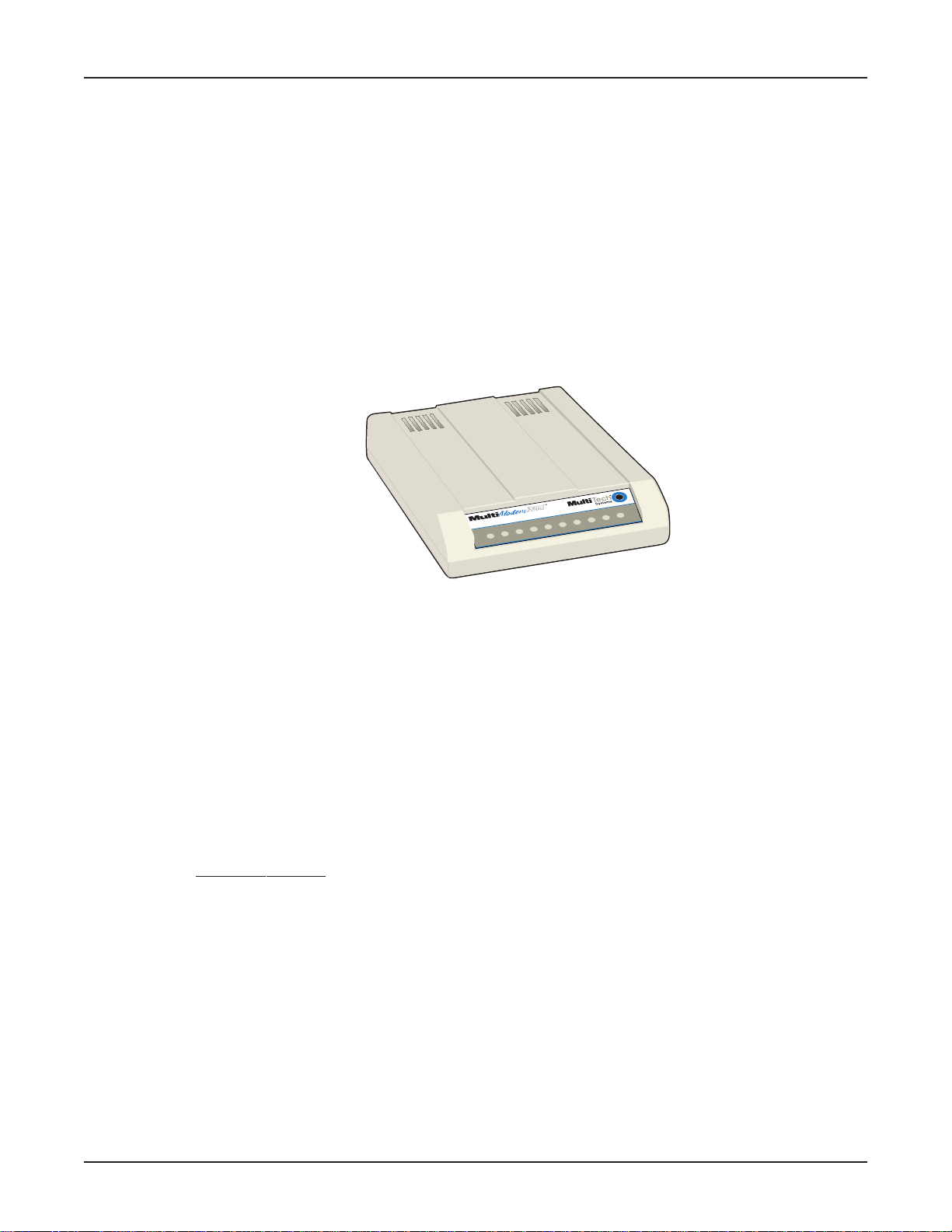
Product Description
The MTA128ST-USB is a desktop terminal adapter with an ST port used for connection to an ISDN
network, a USB port for connection to a PC or laptop, and an analog port to connect to a telephone,
modem, or fax machine. It ships with a softw are configuration utility for Windo ws® 2000 and Windo ws
98/95. In addition, the MTA128ST-USB accepts AT commands that enable it to use the same
communications software as an analog modem.
Figure 1-1: MT A128ST-USB (Front View)
The MTA128ST-USB is compatible with the popular EuroISDN switch protocol, it communicates using
ISDN BRI (2B+D) service, which provides up to 128 Kbps data and voice communications, and it
automatically detects whether an incoming call is voice or data and handles it appropriately.
Universal Serial Bus (USB)
Universal Serial Bus (USB), defined by a consortium of industry leaders, permits connection of
multiple low-speed and medium speed computer peripheral devices such as telephones, modems,
printers, keyboards, mice, and scanners; all from a single personal computer port. The specification,
based on open architecture has become a standard feature in new desktop and notebook computers.
For more details, ref er to the USB Public W eb Board on the W orld Wide W eb at:
http://www.usb.org/
2
P
t
r
o
P
g
o
l
a
n
A
h
t
i
w
m
e
d
o
M
N
D
S
I
B
S
U
D
R
D
T
R
T
2
B
1
B
S
L
1
P
8
2
1
H
O
6
Page 7

Manual Organization
This manual is divided into six chapters and two appendixes:
Chapter 1 - Introduction and Description
Chapter 1: Introduction and Description
specifications, and provides an ov erview of the manual’s organization.
Chapter 2: Hard ware Installation
power , to the ISDN BRI line, and to an optional analog de vice . It also describes the functions of the
front panel LED indicators.
Chapter 3: Software Installation and Configuration —
and how to configure and operate the MTA128ST -USB using the Windo ws 2000/98/95 software
configuration utility .
Chapter 4: A T Commands, S-Registers, and Result Codes
S-registers, and result codes to control the MT A128ST-USB through popular communications
programs.
Chapter 5: Troubleshooting
you think it isn’t working correctly.
Chapter 6: W arranty , Service, and T echnical Support
how to upgrade your unit using the FlashWizard utility, and describes how to get technical support via
telephone and the Internet.
Appendix A: Regulatory Compliance
Appendix B: Configuration Profiles
in the MTA128ST-USB’s firmware and lists contents of each profile.
—Describes how to connect the MT A128ST-USB to the computer, to
—Provides tips and advice for troubleshooting y our MT A128ST-USB if
—Summarizes product features, lists technical
Describes how to install the driver software
—Describes how to use A T commands,
—Provides terms of your warranty , describes
—EMC, Saf ety , and Terminal Directive Compliance.
—Describes how to use the Quick Setup Factory Profiles stored
7
Page 8

MultiModemISDN User Guide
Features
The MT A128ST-USB communicates over public ISDN telephone lines. F eatures include:
• Compatibility with EuroISDN (ETSI/DSS1/NET3), French VN4, and Japanese INS64 s witch
protocols
• USB interface for easy installation; hot-s wappable (Windows 2000 and Windows 98) with other
USB devices without restarting or reconfiguring your PC
• Compatibility with U.S. NI-1, AT&T 5ESS, and DMS-100 switch protocols
• Compatibility with V.110*, V.120, ML-PPP, and X.75 protocols
• ISDN BRI (2B+D) and analog ports
• USB port (T ype B)
• Support of PPP (Point-to-Point Protocol) f or high speed ISDN connections
• Tone detection to allow use of a standard telephone f or ISDN line access (an ISDN telephone
is not required)
• Automatic detection of incoming calls as voice or data
• Windows 2000 and Windows 98/95 software utility f or easy ISDN line configuration
• AT commands, S-registers , and result codes
• Ability to use the same communications software as analog modems
• Flash memory for easy firmware upgrades
* The MTA128ST -USB is manuf actured in two b uilds. To determine the build of your terminal
adapter (T A), issue the ATI2 command in a terminal window. If the TA responds to the command
with MTA128ST-USB, then it supports V.110. If your TA resonds to the A TI2 command with
MTA128ST-USB-RC, V.110 support is not availab le.
8
Page 9

Technical Specifications
Your MTA128ST-USB terminal adapter meets the following specifications:
Chapter 1 - Introduction and Description
T rade Name
Model Number
Network Interface
Switch Compatibility
B-Channel Protocols
V oice Coding
LED Indicators
Data Connections
Command Interface
Connectors
MultiModemISDN
MT A128ST-USB (International)
Four-wire S/T interface
EuroISDN (ETSI/DSS1/NET3), VN4, INS64, U .S . NI-1, AT&T 5ESS,
DMS-100
V.110*, V .120, X.75, ML-PPP
PCM: A-Law (Europe); µ-Law (US)
10 front panel LED indicators: Transmit Data, Receive Data, Call Status,
B1 Active, B2 Active, Terminal Ready, Off Hook (AUX port), 128 Kbps,
P1 Active (data protocol), P2 Active (data protocol)
T wo ISDN B-channels
One ISDN D-channel
One analog port for connecting a standard telephone, modem, or fax
machine
AT commands, S-registers , result codes,
Windows 2000/98/95 configuration utility, and
Windows 2000/98/95 Dial-Up Networking (DUN)
USB: Type B connector
ISDN: RJ-45 female receptacle, 4-wire S/T (accepts connection cable
to the network provider’ s NT1 device)
AUX: RJ-11 f emale receptacle
Switches
Power Requirements
Dimensions
Environmental
Power Consumption
Weight
Warranty
* The MTA128ST -USB is manuf actured in two b uilds. To determine the build of your terminal
adapter (TA), issue the ATI2 command in a terminal window . If the TA responds to the command
with MTA128ST-USB, then it supports V.110. If your TA resonds to the A TI2 command with
MTA128ST-USB-RC, V.110 support is not availab le.
T wo-position po wer switch
T wo-prong outlet-mounted tr ansformer (included), 240 V A C
50/60 Hz
15.0 cm × 10.7 cm × 2.8 cm (L × W × D)
T emperature range 0°–50° C;
Humidity range 20–90% (noncondensing)
4 watts
224 g (8 oz)
5 years
9
Page 10

Chapter 2 - Hardware Installation
Page 11

Introduction
This chapter details the contents of the MTA128ST-USB shipping container, describes each cable
connection, and describes the LED indicators.
Unpacking Y our MT A128ST -USB
The shipping box contains the MTA128ST -USB, an e xternal power supply , one RJ-45 line cord, one
USB cable, your Quic k Start Guide, and three diskettes (i.e., MTA128ST -USB User Guide , MTA128ST USB Driver Software, and ISDN Configuration Utility). Inspect the contents for signs of any shipping
damage. If damage is observed, do not power up the unit; contact Multi-Tech’s Technical Support for
advice (refer to Chapter 6). If no damage is observed, place the MTA128ST -USB in its final location
and refer to “Assemb ling the MTA128ST -USB” in the next section.
USB ISDN Modem with Analog Port
1
B
S
L
D
R
D
T
Chapter 2 - Hardware Installation
2
P
1
P
8
2
1
H
O
R
T
2
B
M
A
D
E
I
N
U
.
S
.
A
M
Figure 2-1. Unpacking
Safety W arning Telecom/ISDN-ST
1. Never install telephone wiring during a lighting storm.
2. Never install telephone jacks in wet locations unless the jack is specifically designed for wet
locations.
3. This product is to be used with CE approved/marked computers.
4. Never touch uninsulated telephone wires or terminals unless the telephone line has been
disconnected at the network interface.
5. Use caution when installing or modifying telephone lines.
6. Av oid using a telephone (other than a cordless type) during an electrical storm. There ma y be a
remote risk of electrical shock from lightning.
7. Do not use the telephone to report a gas leak in the vicinity of the leak.
8. To reduce the risk of fire, use only No . 26 A WG or larger telecomm unication line cord.
9. If S/T - interface ISDN network connection cable is used, the ISDN phone cord
should be connected between the ISDN network connection cable and a NT1 device.
A
.
S
.
U
N
I
E
D
A
11
Page 12
MultiModem ISDN User Guide
Assembling the MTA128ST-USB
The only assembly required is to mount the feet on the bottom of your unit (See Figure 2-2). Peel the
four self-adhesive plastic feet off the backing strip and press them into the recesses on the bottom of
the MT A128ST-USB.
Figure 2-2. Mounting the Feet
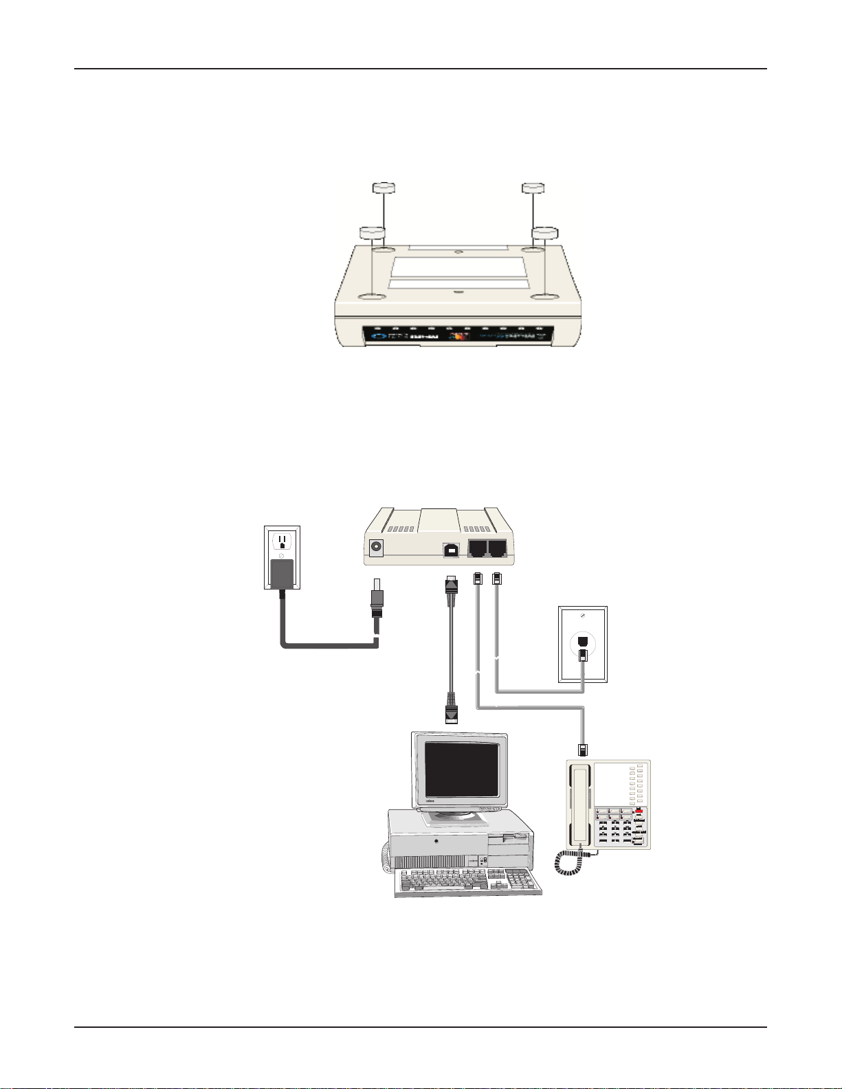
Connecting the MTA128ST-USB to Your System
Place the MTA128ST-USB terminal adapter in a convenient location. In a typical configuration, y ou will
need to connect your MTA128ST-USB to your computer’s USB port, to its own power supply, to the
ISDN network terminator, and to any optional analog equipment you are using (e.g., a telephone). Each
cabling procedure is shown in Figure 2-3.
POWER
USB
PHONE
ISDN
Figure 2-3. MT A128ST-USB Connections
12
Page 13

Chapter 2 - Hardware Installation
Connecting to Your Computer
1. Plug the 4-pin flat end (Type A) into a USB port connector on your computer or laptop.
Note: Do NO T plug the “D-shaped” end (Type B) of the USB cable into the USB connector on the
back panel of the MTA128ST -USB at this time. You will be directed to make the connection when
installing the software drivers.
Connecting to Power
1. Plug the power supply into the unit’ s POWER connector .
2. Plug the power supply into a live AC outlet.
3. Turn on the unit by sliding the power s witch to ON.
4. V erify operation by observing the LED indicators on the front panel. The LEDs will initially flash in
a self-test pattern, then the LS LED remains on. (See LED descriptions on the next page.) If the
terminal adapter does not appear to be working, see Chapter 5 for troubleshooting help.
Caution: Only use the power supply shipped with your MTA128ST -USB; any other pow er supply
could damage the unit and void its warranty.
Connecting to Your ISDN Network Terminator
1. If you need a longer line cord than the RJ-45 line cord provided with your MTA128ST-USB, select a
cord that is wired straight through (pin 1 to pin 1; pin 2 to pin 2, etc.) with at least the middle four
pins connected (pins 2, 3, 4, and 5).
2. Plug one end of the provided RJ-45 S/T line cord into the ISDN jack on the MTA128ST -USB and
the other end into the S/T jack on your network terminator.
Note: The A UX jack and ISDN jac k are not interchangeable.
Connecting to Analog Equipment
You can connect an analog device such as an analog telephone, modem, or fax machine to the unit.
Simply plug a modular RJ-11 telephone cord into the RJ-11 AUX connector .
Note: The A UX jack and the ISDN jack on the unit are not interchangeab le.
13
Page 14
MultiModem ISDN User Guide
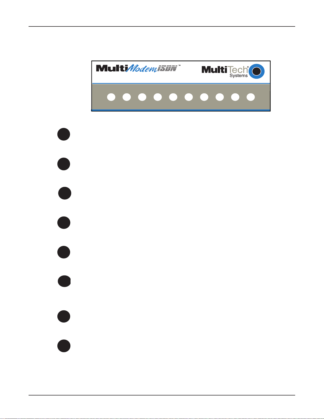
LED Indicators
The ten LED indicators on the front panel (see Figure 2-4) of the MT A128ST-USB report status and
line activity.
USB ISDN Modem with Analog Port
TD RD LS B1 B2 TR OH 128 P1 P2
Figure 2-4: Front Panel
TD
RD
LS
B1
B2
TR
T ransmit Data
Flashes when data is being transmitted (on for a space, off for a mark).
Receive Data
Flashes when data is being received (on for a space, off for a mark).
Power
Lights when the unit is turned on.
Bearer Channel 1 (B1)
When lit, indicates active data or voice connection on bearer channel 1.
Bearer Channel 2 (B2)
When lit, indicates active data or voice connection on bearer channel 2.
Terminal Ready
14
OH
128
Lights to indicate that the computer is communicating with the MTA128STUSB, so the MTA128ST -USB can answ er an incoming call.
Off Hook
Lights when analog equipment on AUX port is active or off-hook.
128 Kbps
Lights to indicate that the B channels have been multiplexed into a single
128 Kbps communications link.
Page 15
Chapter 2 - Hardware Installation
P1
P2
* The MTA128ST -USB is manuf actured in two b uilds. To determine the build of your terminal
adapter (TA), issue the ATI2 command in a terminal window . If the TA responds to the command
with MTA128ST-USB, then it supports V.110. If your TA resonds to the A TI2 command with
MTA128ST-USB-RC, V.110 support is not availab le.
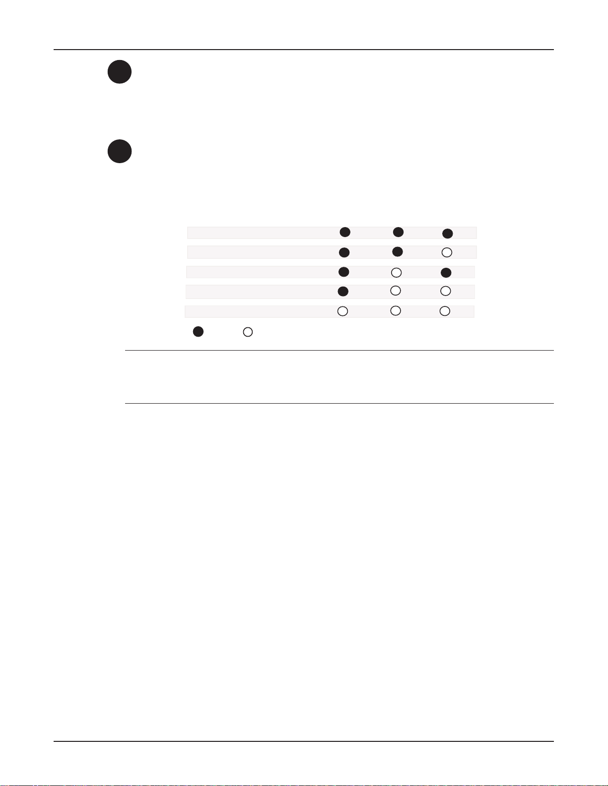
Data Protocol
Lights in combination with P2 and 128 LEDs to indicate which data protocol
(V.110 [build MTA128ST-USB only] , V.120, X.75, PPP, MLPPP) is in use as shown in the
table below .
Data Protocol
Lights in combination with P1 and 128 LEDs to indicate which data protocol
(V.110*, V.120, X.75, PPP, MLPPP) is in use as shown below:
Data Protocol 128 LED P1 LED P2 LED
V.110
V.120
X.75
PPP (1 channel)
MLPPP (2 channels)
OFF ON
References
The World Wide Web is an excellent source of information about terminal adapters, terminal adapter
installation, configuration, and troubleshooting. The f ollowing W eb sites are good places to start:
• Costmo’s Other Resources P age:
• Data Communications F AQ:
• Multi-Tech Systems, Inc.:
http://modems.rosenet.net/or/
http://www.best.com/~malch/comfaq.html
http://www.multitech.com/
15
Page 16

Chapter 3 - Software Installation and Configuration
Page 17
Introduction
This chapter describes how to install the MTA128ST-USB driver software and discusses how to
configure the unit to match your ISDN service and remote terminal adapter (TA). MTA128ST -USB driver
software is installed in Windo ws 2000, Windows 98, and Windows 95 operating en vironments.
Installing in Windows 2000
1. Po wer up your Windo ws 2000 system.
2. T urn on your MTA128ST -USB. The LS (P ower) LED will light.
3. Plug the “D-shaped” end (Type B) of your USB cable into the USB connector on the back of the
unit (See Figure 2-3).
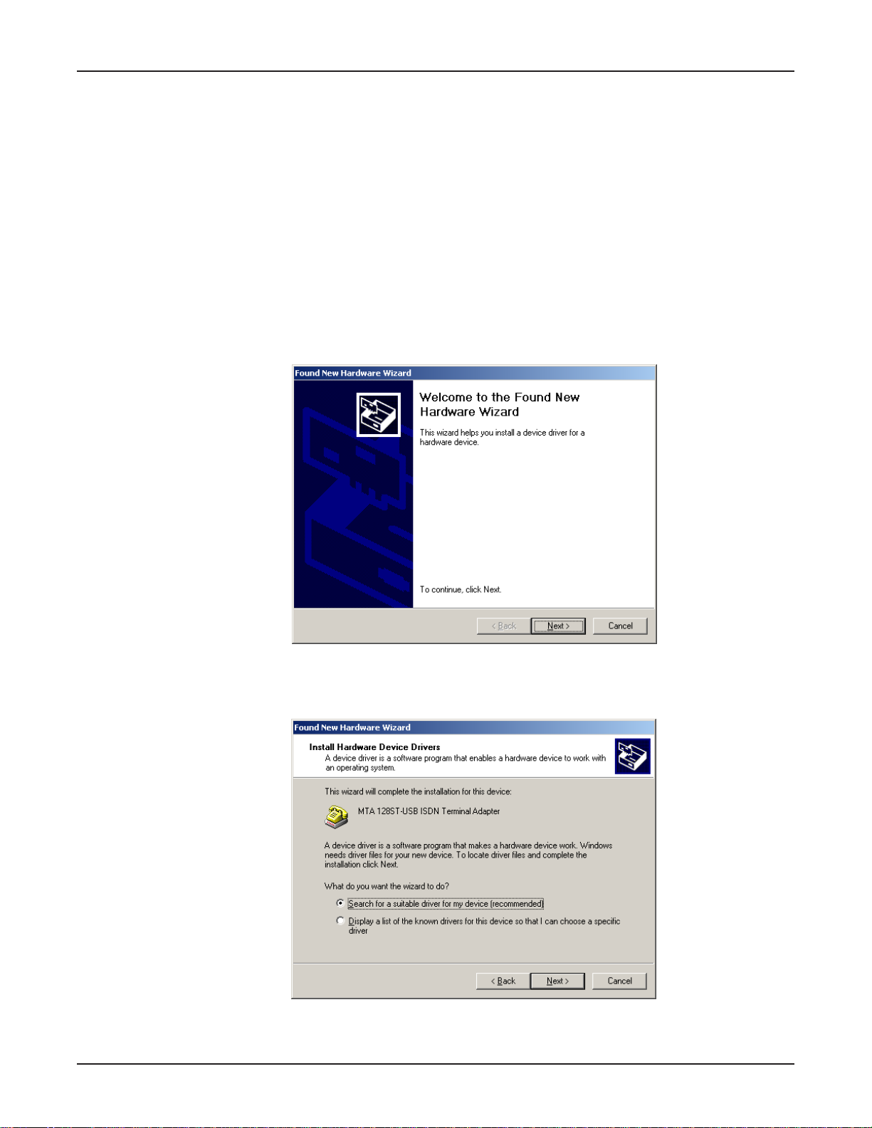
4. Windows will detect that the new modem is present and launch the Found New Hardware
Wizard.
Chapter 3 - Software Installation and Configuration
Place the Installation diskette provided with your modem into your floppy drive and click Next > to
proceed with the installation.
5. The Install Hardware Device Drivers dialog box displays.
V erify that the “Search f or a suitable driv er f or my de vice (recommended)” option is selected and
click Next >.
17
Page 18
MultiModemISDN User Guide
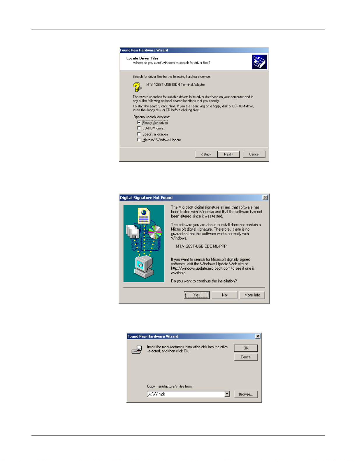
6. The Locate Driver Files dialog box displays.
Verify that the “Floppy disk drives” option is selected and click Next >.
7. If the Digital Signature Not Found dialog box displays,
18
click Yes to continue.
8. The Found New Hard ware Wizard asking you to insert the installation diskette displays .
In the
Copy manufacturer’s files from:
A:\Win2k in the box. Make certain that the installation diskette is in drive A:\ and click OK.
box, use the browse b utton to find A:\Win2k, or type
Page 19
Chapter 3 - Software Installation and Configuration
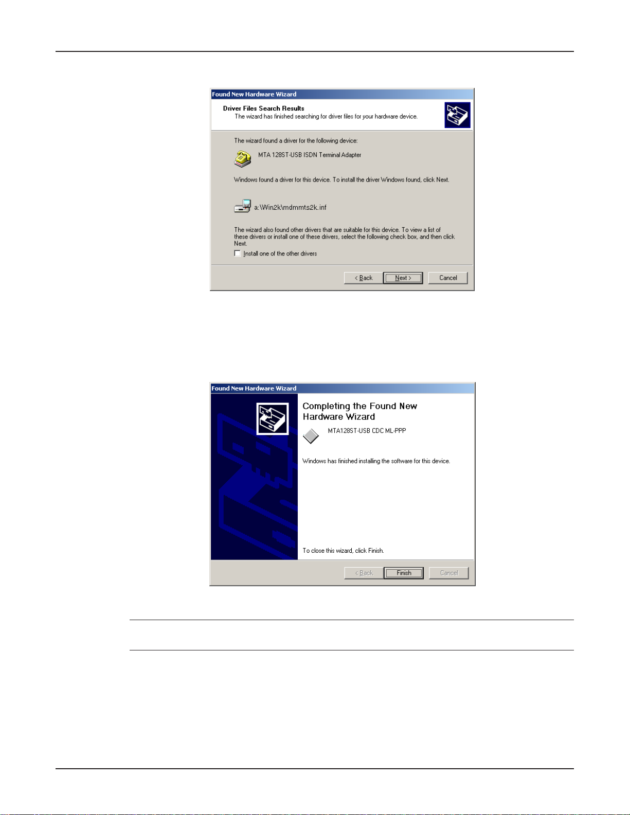
9. The Driver Files Search Results dialog box displays.
Windows indicates it has found the de vice drivers and is ready to cop y them to your computer.
Click Next >.
10. Windows copies the files to your computer and then displays the Completing the Found New
Hardware Wizard dialog box.
Click Finish to complete installation and exit the wizard.
Note: Click My Computer | Properties | Device Manager to verify that the driver software has
been installed.
19
Page 20
MultiModemISDN User Guide
Changing the Modem Descriptor (Windows 2000)
The following procedure describes how you can change the description of the terminal adapter. The
default descriptor is MTA128ST -USB CDC ML-PPP.
Note: If you need assistance , contact Multi-Tech’s Technical Support group.
1. Click Start | Settings | Control Panel | System to display the System Properties dialog box.
2. Click the Hardware tab.
3. Select the Device Manager option to display the Device Manager screen.
4. Expand the modem list and highlight the default descriptor - MTA128ST -USB CDC ML-PPP.
5. With the MTA128ST-USB CDC ML-PPP entry still highlighted, right-click and select the
Properties button.
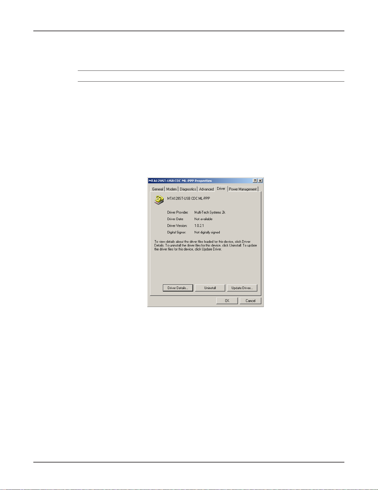
6. Click the Driver tab .
7. The MT A128ST-USB CDC ML-PPP Properties dialog box displa ys.
20
Click the Update Driver button.
Page 21
Chapter 3 - Software Installation and Configuration
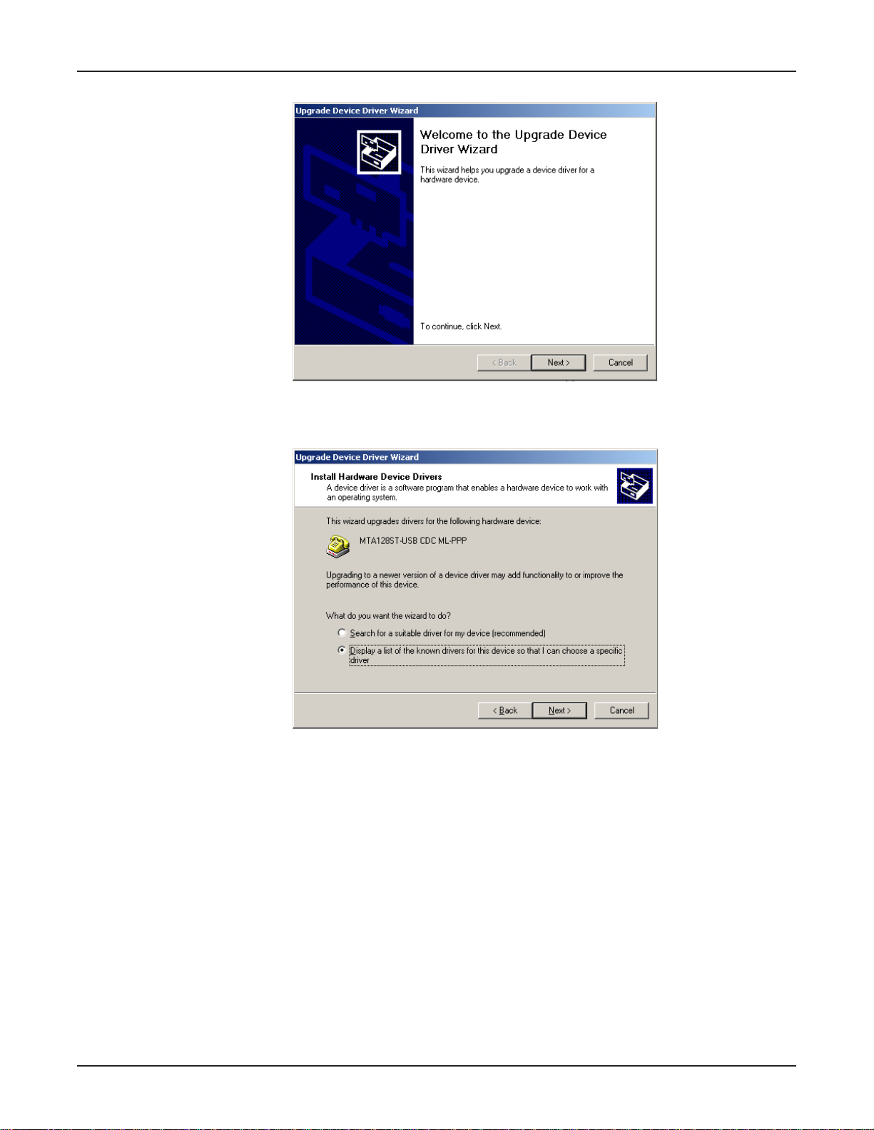
8. The Upgrade Device Driver Wizard dialog box displa ys.
Click Next >.
9. The Install Hardware Device Drivers dialog box displays.
Select “Display a list of the known drivers for this device ...” and then click Next >.
21
Page 22
MultiModemISDN User Guide
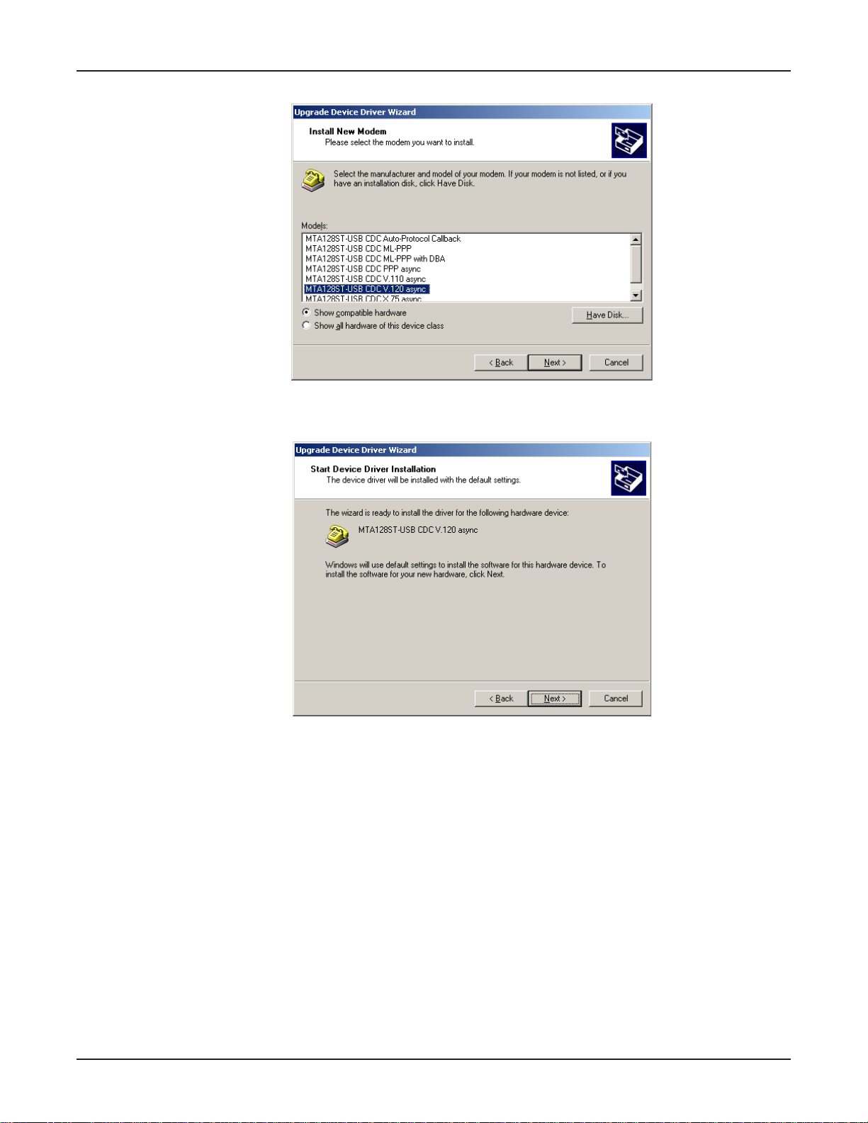
10. The Install New Modem dialog box displays.
Select the appropriate descriptor (e.g., MT A128ST-USB CDC V .120 async) and click Next >.
11. The Start Device Driver Installation dialog box displays.
22
Click Next > to start the device driver installation.
12. If the Digital Signature Not Found screen displays, click Yes to continue the installation.
Page 23
Chapter 3 - Software Installation and Configuration
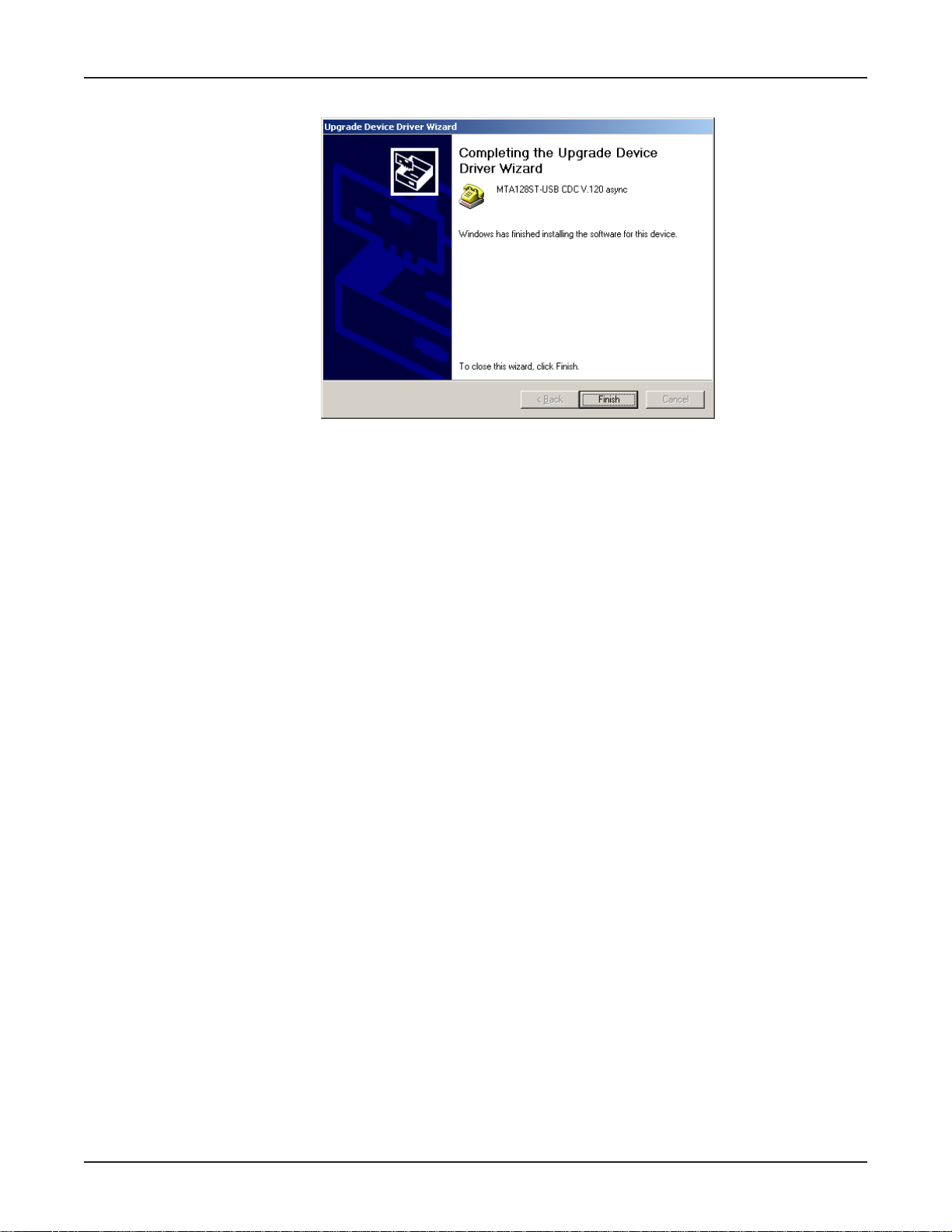
13.The Completing the Upgrade De vice Driver Wizard dialog bo x displays .
Click Finish.
14. The Properties dialog box displays. Click Close and then close all remaining screens.
23
Page 24
MultiModemISDN User Guide
Installing in Windows 95/98
Installing the USB device within Windows 95/98 inv olv es first creating a port within Windows, then
installing the USB device driver . The instructions which follow guide y ou through the Windows 98
installation process. Although the screens diff er slightly, the Windows 95 installation process is
similar.
Only certain versions of Windows 95 (OSR2.1, Revision C) off er support for USB peripherals. If y ou
are unsure if your Windo ws 95 system supports USB, a free USB ev aluation utility is a v ailab le from
the Shopping Bag page at http://www.usb.org/shopping_bag.html. Do wn-load the utility (287K) and run
the .exe application to determine if you ha ve USB support.
1. Po wer up your Windows system.
2. T urn on your MTA128ST -USB. The LS (P ower) LED will light.
3. Plug the “D-shaped” end (Type B) of your USB cable into the USB connector on the back of the
unit (See Figure 2-3).
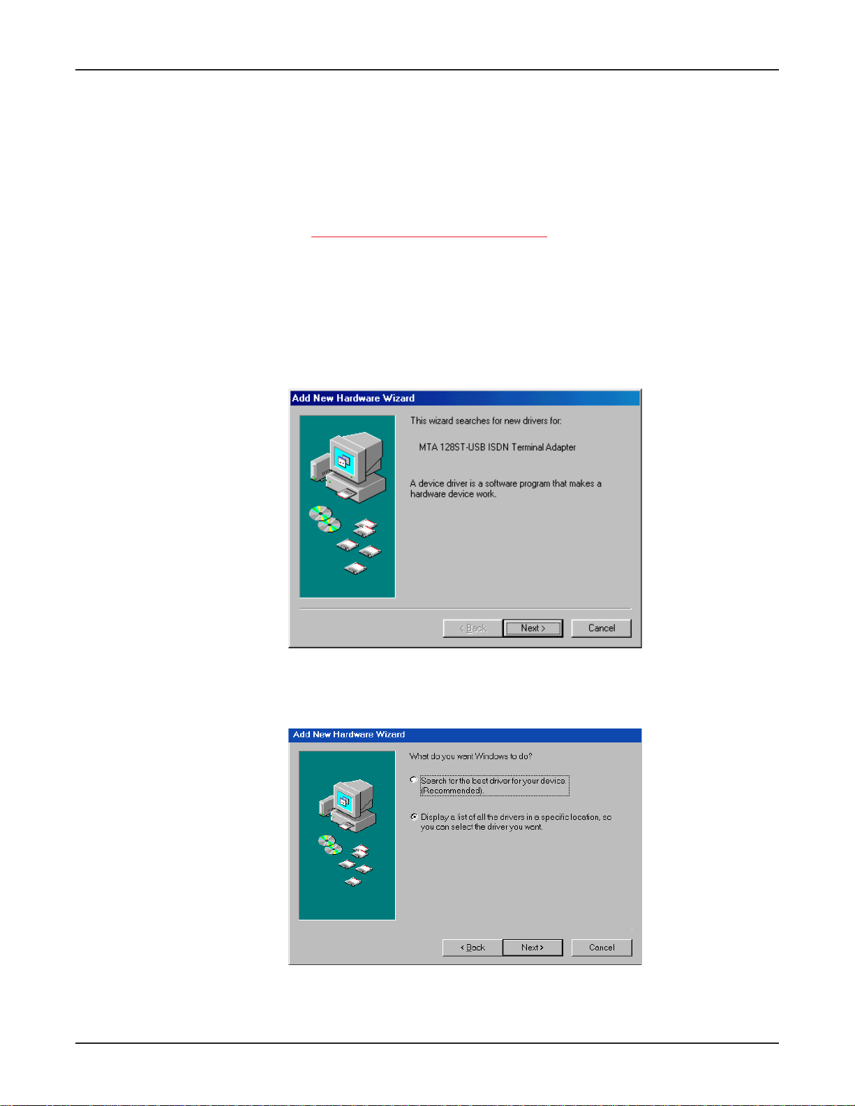
4. Windows will detect that the new modem is present and launch the Add New Har dware Wizar d.
24
Place the Installation diskette provided with your modem into your floppy drive and click Next > to
proceed with the installation.
5. The Ad d New Hard ware Wizar d dialog box displa ys, asking
Select Display a list of all the drivers in a specific location so you can select the driver you want.
Click Next >.
What do you want Windows to do?
Page 25
Chapter 3 - Software Installation and Configuration
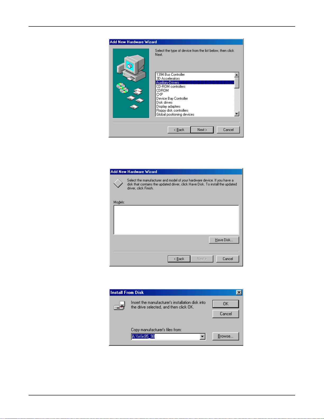
6. The Add New Hard ware Wizar d displa ys a list of device types.
Select Auxiliary-Drivers and click Next>.
7. The Add Ne w Hard ware Wizard displa ys , asking you to select the manuf acturer and model of
your hardware device.
Click Have Disk....
8. The Install from Disk dialog box displays.
Ensure the MTA128ST-USB diskette has been inserted into the computer’s floppy disk drive (A:\ ).
In the
Copy manufacturer’s files from:
field, type A:\Win95_98, then click OK.
25
Page 26
MultiModemISDN User Guide
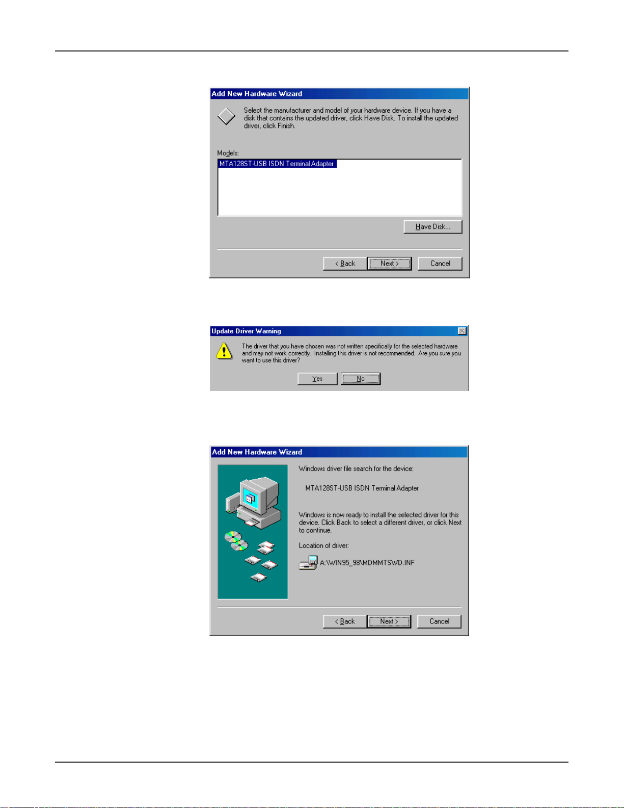
9. The Ad d New Hard ware Wizar d dialog box requests y ou to select the manufacturer and model of
your hardware device.
Select the
10. The Update Driver W arning dialog box displa ys.
Click Yes to continue the installation.
11. The Add New Hard ware Wizar d dialog bo x displays indicating it has located the driv er on the
diskette.
MT A128ST-USB ISDN Terminal Adapter
, and click Next>.
26
Click Next>.
Page 27
Chapter 3 - Software Installation and Configuration
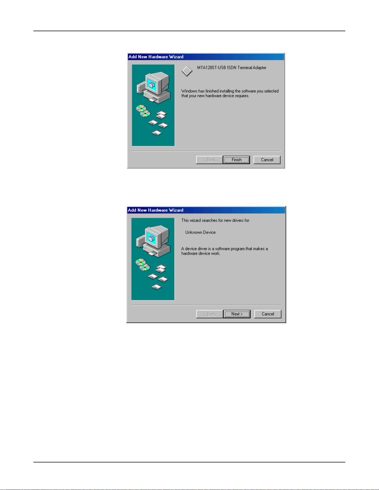
12. A progress indicator displays as files are copied to the system. The Add Hardware Wizard
displays indicating that Windo ws has finished installing the software f or the de vice.
Click Finish.
13. The Add New Hardware Wizard dialog box displays indicating it is searching for new driv ers for
an
Unknown Device
.
Click Next>.
27
Page 28
MultiModemISDN User Guide
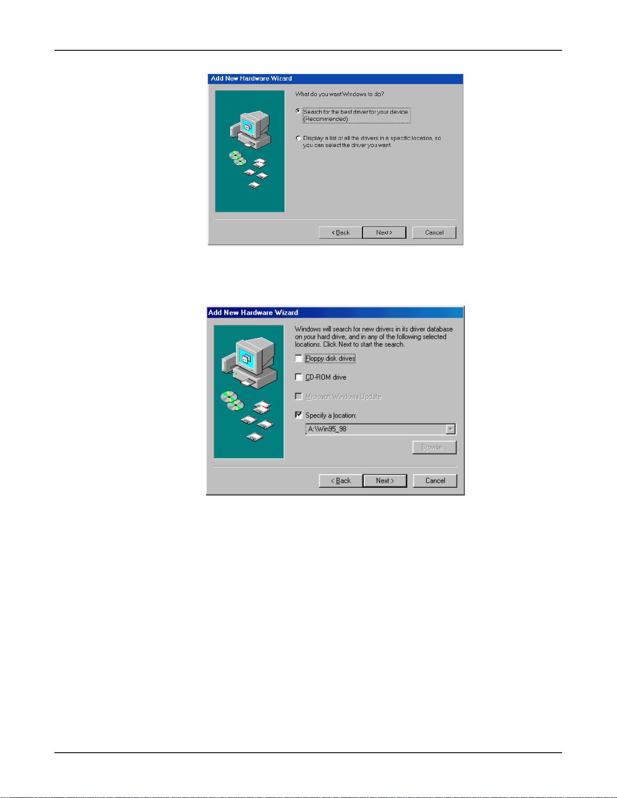
14. The New Hard ware Wizard displa ys asking,
Select
15. The Add New Hardware Wizard dialog box displays, indicating Windows will search for new
drivers in the location you select.
Search for the best driver for your device (Recommended)
What do you want Windo ws to do?
. Click Next>.
28
Select
the computer’s floppy disk drive and click Next > .
Specify a location
. Type A:\Win95_98 in the box. Ensure the MTA128-USB diskette is in
Page 29
Chapter 3 - Software Installation and Configuration
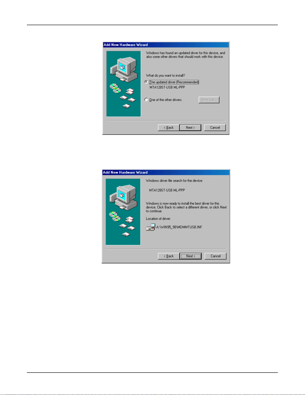
16. The Add New Har dware Wizard dialog bo x displays , indicating Windows has found an updated
driver for this device.
Ensure Select the updated driver (Recommended) MTA128ST-USB ML-PPP is selected. Clic k
Next>.
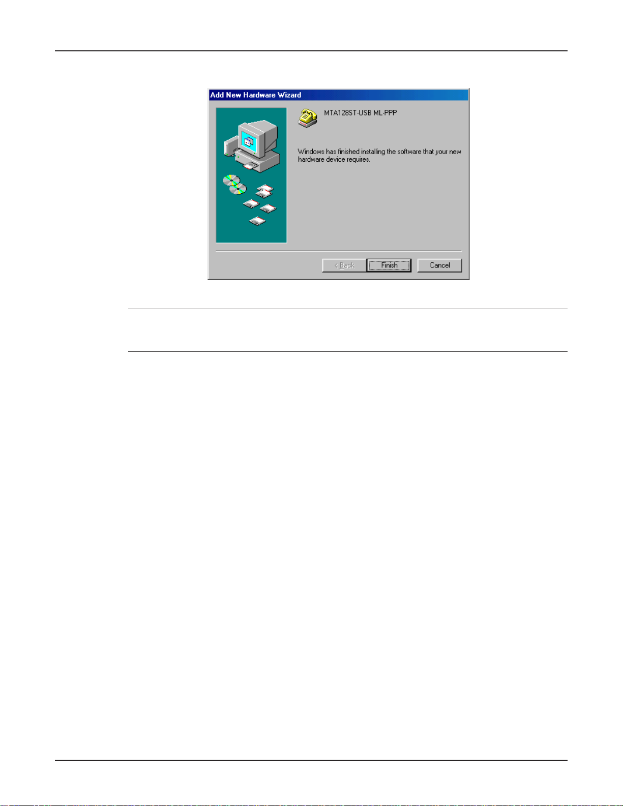
17. The Add New Hard ware Wizar d dialog box displa ys indicating that Windows has selected the
proper driver from the installation disk and displays the information for verification.
Click Next > to install the driver.
29
Page 30
MultiModemISDN User Guide
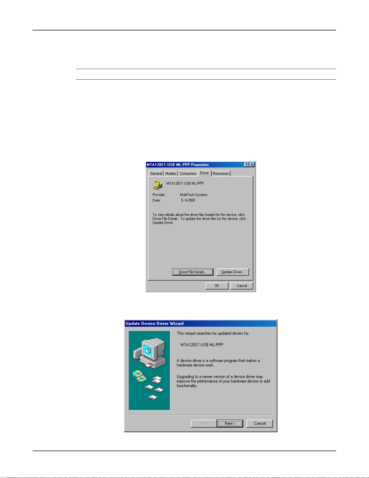
18. Windows proceeds to copy the files to the system and then displays the Add New Hardware
Wizard dialog box, indicating that Windows has finished installing the software .
Click Finish to complete the installation and exit the wizard.
Note: To verify successful installation of the Auxiliary Drivers and the MT A128ST-USB modem, right
click My Computer, then select Properties | Device Manager. Expand the A uxiliary Drivers and
Modem icons to view the MTA128ST -USB information.
30
Page 31
Chapter 3 - Software Installation and Configuration
Changing the Modem Descriptor (Windows 95/98)
The following procedure describes how you can change the description of the terminal adapter. The
default descriptor is MTA128ST -USB ML-PPP.
Note: If you need assistance , contact Multi-Tech’s Technical Support group.
1. Click Start | Settings | Control Panel | System to display the System Properties dialog box.
2. Select the Device Manager option to display the Device Manager screen.
3. Expand the modem list and highlight the default descriptor - MTA128ST-USB ML-PPP.
4. With the MTA128ST-USB ML-PPP entry still highlighted, right-click and select the Properties
button.
5. Click the Driver tab .
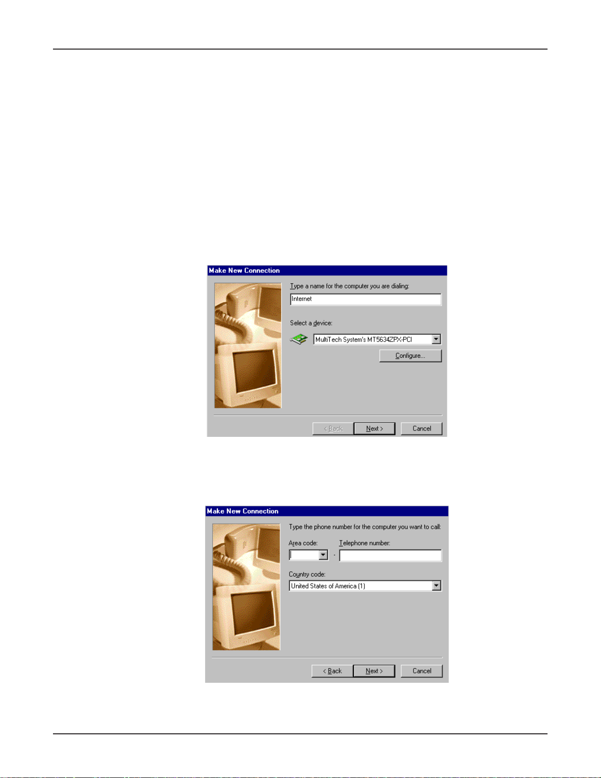
6. The MT A128ST-USB ML-PPP Properties dialog box displays.
Click the Update Driver button.
7. The Update Device Driver Wizard dialog box displa ys.
Click Next >.
31
Page 32

MultiModemISDN User Guide
8. The Update Device Driver Wizard dialog box displa ys.
Select “Display a list of all the drivers in a specific location, ...” and then click Next >.
9. The Upgrade Device Driver Wizard dialog box displa ys.
32
Select the appropriate descriptor (e.g., MTA128ST-USB V .120 async) and click Ne xt >.
10. The Update Driver W arning screen displays . Click Yes to continue the installation.
Page 33

Chapter 3 - Software Installation and Configuration
11. The Update Device Driver Wizard dialog bo x displa ys indicating that it is ready to install the
selected driver.
Click Next > to begin installation.
12. Once installtion is completed, the Update Device Driver Wizard dialog box displa ys , indicating
Windows has finished installing the drivers.
Click Finish.
13. The Properties dialog box displays. Click Close and then close all remaining screens.
33
Page 34

MultiModemISDN User Guide
Removing Your Old Device from Windows 2000 and Windows 98/ 95
When your new MTA128ST -USB replaces another terminal adapter, the old installation remains in
Windows 2000 and Windows 98/95 after y ou install the ne w de vice, and the old de vice is still selected
in HyperT erminal and other Windows 2000 and Windows 98/95 applications . Although y ou can change
the application connection descriptions one at a time, it is easier to force Windows applications to use
the new device by removing the old modem from Windo ws.
1. Click Start | Settings | Control Panel.
2. For Windows 98/95 users, doub le-click the Modems icon to displa y the Modems Properties
dialog box.
For Windows 2000 users, clic k the Phone and Modem icon to displa y the Phone and Modem
Options dialog box, then click the Modems tab .
3. In the list box, select (highlight) the device to be deleted.
4. Click Remove and then click Close to remove the device from your system.
5. The next time you dial a HyperTerminal connection, it will select your new device and ask you to
confirm the selection.
34
Page 35

Configuration
Run the ISDN MT A128ST-USB configuration utility for North American customized ISDN settings.
Note: For Europe, run the configuration utility to customize the settings of the terminal adapter
such as configuring Multiple Subscriber Numbers (MSNs).
Configure the unit to match your ISDN service and the remote terminal adapter (T A) with any of three
methods listed below:
•
ISDN MT A128ST -USB Configuration Utility
This configuration utility is recommended for computers running Windows 2000/98/95
operating systems. Because it is a softw are-based utility, you can use it to create and store
as many configurations as you want.
•
Windows 2000/98/95 Dial-Up Networking
Dial-Up Networking (DUN) allows systems using Windows 2000/98/95 to easily configure a
modem connection to another computer or network system.
•
A T Commands
If you prefer using AT commands or want to fine tune the operation of your unit, configure your
unit by using AT commands and S-registers much as you would configure an analog modem.
Enter these commands in your data communication program’ s terminal mode. AT commands
are described in detail in your on-line User Guide.
Chapter 3 - Software Installation and Configuration
Whatever method y ou use to configure your MTA128ST -USB, complete the f ollowing Network
Configuration planning sheets before beginning the configuration process. Refer to the planning sheets
during the configuration procedure.
Network Configuration
Network Switch T ype
Select the network switch type your ISDN service provider uses at its local central office. You can set
the MTA128ST-USB to NET3 (DSS1), VN4, INS64, U.S . NI-1, AT&T 5ESS, or DMS-100. If y ou don’t
know the switch type, get the inf ormation from your ISDN service provider .
Data TEI
Data TEI (Terminal Endpoint Identifier) is the TEI assigned to the data channel. Y ou can select A uto
TEI, a fixed TEI, or Disable. A TEI is a number used by the central office switch to uniquely identify
each device connected to the network. When it uses dynamic TEI assignments (Auto TEI), the central
office switch assigns a TEI each time the unit connects to the network. However , the ISDN service
provider may assign a fix ed TEI at subscription time, in which case you must configure the unit with
the fixed TEI number. You can also disable the channel, which may be useful when multiple units are
attached to a network terminator bus.
Voice TEI
Voice TEI is the TEI assigned to the voice channel. Choices are: A uto TEI, a fixed TEI number, or
Disable.
________________________________________
___________________________________
A T command: *!D3=
_____________________________
AT command: !C0=
A T command: !D3=
Data MSN
The Data MSN (Multiple Subscriber Number) allows a caller to specify an individual MT A128ST-USB
when more than one unit is connected to your network terminator. If y ou don’t assign a value to the
MSN, the unit accepts all incoming calls. If you only assign a base address to the MSN, the unit
___________________________________
35
Page 36

MultiModemISDN User Guide
accepts any incoming call with the same base address, regardless of whether a subaddress is
included. If you assign a base address and a subaddress to the MSN, the unit only accepts calls that
match both the base address and the subaddress. The f ollowing e xamples show the syntax f or setting
the MSN with and without a subaddress.
MSN with subaddress: AT!N1=5551000:001 (base address is 5551000; subaddress is 001)
MSN without subaddress: AT!N1=5551000 (base address is 5551000)
AT command: !N1=
Voice MSN
Selects calls on the voice channel in the same way the Data MSN selects calls on the data channel.
__________________________________
A T command: *!N1=
SPIDs and DNs
For use with North American switches, the Service Profile Identifier (SPID) must be configured in the
MTA128ST-USB. The SPID is assigned by the local phone company and is for the specific BRI line
where the unit is attached. The SPID field is empty prior to configuration.
A T commands
Directory Number (DN) is the phone number another user calls to contact this unit once it is attached
to the ISDN.
A T commands
______________________________
: AT!C6= and AT*!C6=
: AT!N1= and AT*!N1=
Note: SPIDs and DNs are used only b y the U .S . NI-1, AT&T 5ESS, and DMS-100 switch types.
Call Control Configuration
Persistent DTR Dialing
A high DTR (Data Terminal Ready) signal on the USB port indicates your computer or terminal is ready
to communicate with your MTA128ST -USB. DTR normally goes high when a communication program
starts or is ready to dial. Persistent DTR dialing enab les the unit to automatically redial the number
stored in memory location 0 whenever DTR is high and the serial port does not have an active call.
You can enable or disable this feature.
_______________________
AT command: $D
Auto Answer Data Calls
__________
Rings to Answer ___________
Select Auto Answer if y ou want y our MTA128ST-USB to automatically answ er all incoming data calls
(this option does not affect the analog port). The Rings to Ans wer number, in the range of 1 to 255,
selects the number of rings the unit waits before ans wering an incoming call. The def ault is one ring.
AT command: S0=
Dialing Method
Select either the Enbloc or the Overlap dialing method for use when establishing a data call. Your
ISDN provider determines the dialing method. The Enbloc method is used f or most ISDN dialing;
howev er , you can select the o verlap method if y ou are working with a private network.
_____________________________
AT command:
%A97=
Data Protocol
The data protocol, also known as the B-channel protocol and the rate adaption protocol, is the
language spoken
the ISDN link must use identical protocols.
________________________________
over each 64 Kbps channel between tw o ISDN devices . The de vices on both ends of
AT command: !Z=
36
Page 37

Chapter 3 - Software Installation and Configuration
• V .110 Protocol*—Used to connect slo wer , pre-ISDN communications devices to high-speed
ISDN lines. It handles rates up to only 38400 bps and is used mostly in Europe . The de vices
on both ends of the link must be set to identical rates. However, the MTA128ST-USB (by
default) is able to adapt to the network rate of a receiv ed V.110 call even though it has S76 or
$MB set to a different network rate.
* The MTA128ST -USB is manuf actured in two b uilds. To determine the build of your terminal
adapter (TA), issue the ATI2 command in a terminal window . If the TA responds to the command
with MTA128ST-USB, then it supports V.110. If your TA resonds to the A TI2 command with
MTA128ST-USB-RC, V.110 support is not availab le.
• V.120 Protocol—Similar to V.110 protocol, but provides rates up to 64000 bps on each B
channel.
• X.75 Protocol—Pac ket-s witched network protocol for international use. La yer 2 portion of this
protocol is used commonly as a rate adaption protocol.
• MLPPP Protocol—MLPPP (Multi-Link PPP) protocol provides rates up to 64 Kbps per
channel. This protocol uses both B channels at once, pro viding an aggregate data
transmission speed of 128 Kbps.
Dialing Numbers
The MT A128ST-USB can dial telephone number n, where n can be up to 20 characters.
Dn (n
= phone number)
Stored Numbers
The MTA128ST-USB can store as many as ten phone numbers, up to 20 characters each.
_____________________________
A T command:
_____________________________
command: &Z=
Dialing Stored Numbers
The MT A128ST-USB can dial a number previously stored in directory number n with the
command.
A T command: DSn
_______________________
&Zn=x
AT
37
Page 38

MultiModemISDN User Guide
ISDN MTA128ST-USB Configuration Utility
Use the ISDN MT A128ST-USB Configuration Utility with computers running Windows 2000/98/95
operating systems only. Because it is a software utility, you can use it to create and store as many
different configurations as you wish.
To Install in Windows 2000/98/95
1. When installing from disk, insert the Setup disk (provided in your MT A128ST-USB package) into
drive A or B. If installing from a network location, connect to it. (Note the drive letter. You may
need it if you run Setup again.)
2. Click Start | Settings | Control Panel.
3. Double-click the Add/Remove Programs icon.
4. For Windows 98/95 users, clic k Install on the
For Windows 2000 users, click the Add New Programs icon.
5. Follow the instructions that appear on screen.
Install/Uninstall
tab.
To Use the ISDN MTA128ST-USB Configuration Utility
1. To start the utility, click Start | Programs, and then double-click the ISDN MTA128ST-USB
Configuration Utility icon. The ISDN T A Configuration Wizard displays.
38
Select the type of Setup (e.g., Express (Existing), Configuration (e.g., EuroISDN), and then click
Next >. Follow the instructions provided in each succeeding dialog box.
2. Refer to the “Network Configuration” planning sheets completed in the previous section as you
configure the unit. If you have questions about choices in a dialog box, click Help.
3. When you finish configuring the MTA128ST-USB, exit the configuration utility.
Page 39

Chapter 3 - Software Installation and Configuration
Windows 2000 Dial-Up Networking
The following instructions describe all Dial-Up Networking connection options under Windo ws 2000 as
well as guide you through setting up a Dial-up Networking connection to an Internet Service Provider
(ISP).
Note: If you are connecting to the Internet, make sure TCP/IP is installed on your computer and that
you’ve set up an access account with an Internet Service Provider.
1 . To set up a Dial-Up Networking connection within Windows 2000, select
Start | Settings | Network and Dial-up Connections.
2 . In the Network and Dial-up Connections dialog box, double-click the Make New Connection
icon. The Network Connection Wizard dialog bo x is displa yed indicating the Wizard will help in
creating a connection to other computers and networks enabling applications such as e-mail, web
browsing, file sharing and printing.
Click Next>.
3. The Network Connection T ype dialog box is displa yed off ering several connection options.
Select the option which best describes the type of connection you are creating with this definition.
Click Next>.
The process for completing your Dial-Up Networking connection will vary based on the connection type
selected in the previous step.
39
Page 40

MultiModemISDN User Guide
If you select Dial-up to private network and have only one modem installed:
a. The Phone Number to Dial dialog box is displayed. Enter the phone number of the
computer, network or Internet Service Provider (ISP) to which you are connecting. Clic k
Next>.
b. The Connection A v ailability dialog bo x is displa yed. If y ou are creating this connection f or
multiple users, select Create this connection for all users. If this connection will be used
only by you, select Create this connection only for myself. Click Next> to continue.
c. The Completing the Network Connection Wizard dialog bo x is displa yed. Y ou are prompted
for a name to use for this connection. Enter a meaningful name in the box provided, then
click Finish.
If you select Dial-up to the Internet, the Welcome to the Internet Connection Wizard is displayed
as shown below .
a . Select the appropriate option for the type of connection you are making to the Internet and
click Next>. In this example,
connect through a local area network (LAN)”
b. The Setting up your Internet connection dialog box is displayed. Select I connect through
a phone line and modem. Click Next>.
c. If you have only one modem installed, proceed to the next step. If you have more than one
modem installed on your computer , select your Multi-T ech System’ s modem from the list and
click Next>.
d. The Step 1 of 3: Internet account connection information dialog box is displayed. Enter
the Area code, Telephone number and Country/region name and code for your Internet Service
Provider’s access number .
e . Click the Advanced tab to access options for selecting your connection type and logon
procedures. Your ISP should provide this information for your account. If you are not sure
which connection type to choose, try PPP.
Although many ISPs automatically provide an IP address for your machine and their Domain
Name Server (DNS) each time you connect to them, some ISPs do not. If your ISP provided
IP addresses to you, click the Addresses tab. In the IP Address section, select Always
use the following:, and enter the IP addresses into the appropriate boxes. Click OK to return
to Step 1 of 3: Internet account connection, and click Next>.
Note: If your machine has a network adapter installed, do not enter this address in the address box.
Enter the IP addr ess pr ovided by your ISP.
f. The Step 2 of 3: Internet account logon information dialog box is displayed. Enter the user
name and password you will use for your Internet account. Click Next>.
“I want to set up my Internet connection manually, or I want to
was selected
.
40
Page 41

Chapter 3 - Software Installation and Configuration
g. The Step 3 of 3: Configuring your computer dialog box is displayed. In the box provided,
enter a descriptive name for this connection and click Next >.
h. You are then asked if you would like to set up an Internet mail account. You may select Yes or
No. If y ou select yes, you will be asked to provide specific information about your mail
service. In this example, No is selected. Click Next>.
i. The Completing the Internet Connection Wizard is displa yed. Click Finish.
If you select Connect to a private network through the Internet:
a . In the box provided, enter the Host name or IP address belonging to the computer to which
you are calling. Contact the network administrator for the device to which you are connecting
to obtain this information. Click Next>.
b. The Connection A v ailability dialog bo x is displa y ed. If y ou are creating this connection f or
multiple users, select Create this connection for all users. If this connection will be used
only by you, select Create this connection only for myself. Click Next> to continue.
c. The Completing the Network Connection Wizard dialog bo x is displa yed. Y ou are prompted
for a name to use for this connection. Enter a meaningful name in the box provided. Click
Finish.
If you select Accept incoming connections:
This option allows another computer to create a virtual connection to your computer through the
Internet, other public network or a direct cable. Virtual Private connections to your computer through
the Internet are possible only if your computer has a known name or IP address on the Internet.
a. The De vices for Incoming Connections dialog bo x is displa yed. Select your Multi-Tech
System modem and click Next>.
b. At the Incoming Virtual Private Connection dialog box, select either Allow virtual private
connection or Do not allow virtual private connection.
c. The Allowed Users dialog box is displayed. Next, you can Add or Delete users you will allow
to connect to this device. Click Next>.
d. In the Networking Components dialog box, select the boxes next to the name of each
component you want to enable for incoming connections. Click Next>.
e. The Completing the Network Connection Wizar d dialog box is displa yed. In the bo x
provided, enter a meaningful name for this connection and click Finish.
If you select Connect directly to another computer:
This connection option is designed to allow a connection between two computers using a serial,
parallel or infrared port.
a. The Host or Guest dialog box is displayed. Select the role you’d like for
Select Host if this computer has the information you want to access. Select Guest if this
computer will be used to access information on the Host computer.
b. If you select Host, you will be presented with the Connection Device dialog box. Select the
device from the list. After installing the device through the Wizard, you may configure the
connection properties by right clicking on the icon for this connection and selecting
Properties. Upon completion, click Next>.
this
computer.
The Allowed Users dialog box is displayed. Select the check box next to the name of each
user you want to allow to connect to this computer. Clic k Next>.
c. If you select Guest, the Select a Device dialog box is displayed. Select the COM port you’ d
like to use for this connection from the list. Click Next>.
41
Page 42

MultiModemISDN User Guide
d. The Connection A v ailability dialog bo x is displa yed. If you are creating this connection f or
multiple users, select Create this connection for all users. If this connection will be used
only by you, select Create this connection only for myself. Click Next> to continue.
e. The Competing the Network Connection Wizard dialog bo x is display ed. You are prompted
for a name to use for this connection. Enter a meaningful name in the field provided and click
Finish.
42
Page 43
Chapter 3 - Software Installation and Configuration
Windows 98/95 Dial-Up Networking
Windows 98/95 includes a remote-node client called Dial-Up Networking (DUN). Before beginning,
make certain Dial-Up Networking and TCP/IP are installed on your computer .
1 . T o begin your set up:
a. In Windows 95, Click Start | Programs | Accessories |
Dial-Up Networking.
b. In Windo ws 98, Click Start | Programs | Accessories |
Communications | Dial-Up Networking.
2. If this is the first time you hav e set up a connection with Dial-Up Netw orking, the W elcome to
Dial-Up Networking Wizard dialog box is displayed. If the Wizard does not displa y, double-click
the Make New Connection icon to display the Make New Connection dialog box.
3. The Make New Connection dialog box displays. Enter a descriptive name for this connection. In
the Select a de vice: list box, select y our Multi-T ec h System modem from the list.
Click Next>.
4. The Make New Connection dialog box displa ys. Enter the Area code, Telephone number and
Country code for the computer you will be calling with this connection (your ISP’ s access phone
number).
Click Next>.
43
Page 44

MultiModemISDN User Guide
5. The Make New Connection dialog box displays indicating you have created a new Dial-Up
connection.
Click Finish.
6 . From the Dial-Up Networking folder, right click on the Dial-Up Connection just created and select
Properties to open the Modem Properties dialog box.
7. The Modem Properties dialog box displays. Clic k the Server T ypes tab to display the server
property sheet. Select the appropriate Server Type, Log on options, and protocol selections for the
device to which you are connecting (e.g., your ISP).
44
Click OK.
8 . If your ISP requires you to enter IP addresses for their server or DNS (Domain Name Server),
click the TCP/IP Settings button.
Page 45

Chapter 3 - Software Installation and Configuration
9. The TCP/IP Settings dialog box displays.
If your ISP provided you with an IP address for your computer , select Specify an IP ad dress and
enter the static address in the box provided. If your ISP requires you to enter an IP address for
their name server (DNS), select Specify name server addresses and enter the IP addresses
given to you by y our ISP. Click OK to save the TCP/IP values and return to the Server Types tab .
When you hav e completed customizing the modem properties for this connection, click OK.
T o use this connection, doub le-click the Dial-Up Connection icon within the Dial-Up Networking
folder . If prompted, enter your Internet account User Name and Pass word and click Connect.
AT Commands
You can configure the MTA128ST-USB using A T commands, just as y ou would configure an analog
modem. Use this method if y ou pref er to work with AT commands or if you have a special requirement
not addressed by the configuration utilities or Dial-Up Networking.
Using AT Commands to Configure the MTA128ST-USB
1. Connect the MT A128ST-USB to the USB port on your PC.
2. T urn on the MTA128ST -USB. Once the drivers are installed, Windows 98/95 will automatically
detect the presence of the MT128ST-USB and activate the associated COM port.
3. Start a data communication program and select the COM port where the MT A128ST-USB is
connected.
4. Referring to the
the data communications program.
5. When you finish making changes, use the &W command to save and automatically load the
configuration when the MT A128ST-USB is turned on.
Configuration
section, enter the desired A T commands in the terminal window of
6. Quit the data communications program.
For more inf ormation on A T commands, ref er Chapter 4.
45
Page 46

Chapter 4 - AT Commands, S-Registers
and Result Codes
Page 47

Introduction
One of the ways you can comm unicate with and configure y our MTA128ST -USB is to use AT
commands. AT commands are so-called because, with only a few exceptions , each command string
begins with the characters AT. Using AT commands, you can read and set parameters, and perf orm
actions such as dialing.
Note: F or purposes of brevity , the MTA128ST -USB is referred to as the TA (terminal adapter) throughout
this chapter.
Entering AT Commands
If your MTA128ST-USB (TA) is connected to a computer terminal, you can send AT commands to it by
entering them on the keyboard. If the TA is connected to a computer, you can send AT commands to it
by typing them in the terminal window of a data communications program such as HyperTerminal. You
can also send some A T commands indirectly b y configuring your data communications program.
Chapter 4 - A T Commands, S-Register s, and Result Codes
To enter AT commands, use the following format:
cause the TA to interpret the following string as a command. The command string consists of one or
more commands. The carriage return character , <cr>, sends the command string to the TA. If you are
entering a command string in your communication program’s terminal window , insert the carriage
return character by pressing the ENTER key on your keyboard. If configuring a communications
program, you typically must insert the carriage return character by adding ^M to the end of the
command string.
The TA has three modes of operation: off-line command mode (the default state), on-line command
mode, and data mode. The TA responds to A T commands only when it is in one of the command
modes. After the TA establishes a connection and goes on-line in data mode, it interprets any further
characters you enter as data rather than as commands and transmits them to the remote device.
When the TA is in data mode, you can switch it to on-line command mode by sending it an
sequence
When it detects the escape sequence, the TA enters on-line command mode where it responds to
commands while maintaining the connection with the remote device.
. The TA responds to two types of escape sequences:
•
In-band
The in-band escape sequence is
change the value in register S2.
•
Out-of-band
sequence is
sequence only from software,
where the escape sequence is part of the data stream.
+++AT<cr>.
where the escape sequence is outside the data stream. The out-of-band escape
<break >A T<cr>.
You can send the break signal in the out-of-band escape
not
by pressing SHIFT+BREAK on your keyboard.
A T <command string> <cr>
T o change the in-band escape char acter (+),
. The characters
AT
escape
The TA’s command buff er can store 80 characters, including spaces and other characters used in
telephone numbers. If you mistype a command string, before you press ENTER, edit it by using the
backspace or the delete key. As you type a command string, it appears on your monitor screen, letting
you verify your input as you type it.
The AT commands recognized b y the TA are listed by function in this chapter first in an ab bre viated
list, followed by a more detailed list. For an alphabetical list of AT commands, see
the index.
AT commands
in
47
Page 48

MultiModemISDN User Guide
AT Commands by Function
Command Implementation
AT Attention code
Return Command execution
+++AT<cr> In-band escape code
<break>AT<cr> Out-of-band escape code
Switch Configuration
%A97 Dialing method
!C0 Switch type
!C6 Data SPID
*!C6 Voice SPID
!D3 SAPI-0 data TEI
*!D3 SAPI-0 voice TEI
!L List DN, SPID , TEI, Data protocol & switch type
>Dn Embedded Protocol Analyzer
!DNn Disable Data DN/MSN n
*!DNn Disable Voice DN/MSN n
!ENn Enable Data DN/MSN n
*!ENn Enable Voice DN/MSN n
!N1 Data DN/MSN 1
!N2 Data DN/MSN 2
*!N1 Voice DN/MSN
!RXG Rece ive gai n
!TXG Transmit gain
!Z=n Rate adaptation protocol
USB Port Configuration
En Command mode echo
L List telephone numbers
L5 List current operating parameters
L6 List S-register values
L8 Display ISDN status
Qn Status displays
Sr=n Set S-register
Sr? Read S-register
Vn Terse/verbose result codes
Xn Connect messages
Zn Restore parameters to current power-up profile
&Cn DCD (Data Carrier Detect) control
&Dn DTR (Data Terminal Ready) control
&En Flow control
#Xn Send Single Multiple Xoff Characters
&Fn Load quick setup factory profile
&Mn Asynchronous/Synchronous mode
&Rn CTS (Clear To Send) control
&Sn DSR (Data Set Ready) control
&Wn Store active profile
&Zn= Store telephone number
&Jn Automatic Channel Bundling
$Dn Persistent DTR dialing
%En Escape sequence options
48
Page 49

Chapter 4 - A T Commands, S-Register s, and Result Codes
Data Call Commands
A Answer
D Dial
DSn Dial Stored telephone number
&Jn Channel Bundling
H Hang up
In Display product information
On Return on-line
@Config Start ConfigMenu
Command Implementation
Command: AT
Function: Attention Code
Values: n/a
Default: n/a
Description:The attention code precedes all command strings except the A/ command
and escape codes.
Command: RETURN
Function: Command Execution
Default: n/a
Values: n/a
Description:Press RETURN (ENTER) to execute a command. In command examples,
RETURN frequently is abbreviated <cr>.
Command: +++AT<cr>
Function: In-Band Escape Code
Values: ASCII
Default: + (43)
Description:Makes TA enter command mode (without disconnecting the call) when it is
on-line with a remote device. Default escape code is three + characters
followed by the letters AT, up to 80 command characters and a RETURN
(press Enter). The TA escapes to command mode, executes any commands
in the string, and then remains in command mode. Use
change the escape character.
Command:
Function: Out-of-Band Escape Code
Values: n/a
Default: n/a
Description:Places TA in command mode while remaining on-line. Enter a break signal,
<break>AT<cr>
the letters
AT,
up to 80 command characters, and a RETURN (press Enter).
S2=
command to
49
Page 50

MultiModemISDN User Guide
Switch Configuration Commands
Use the following commands to select your network switch type (e.g., EuroISDN Net3) and to specify
other information required to make an ISDN connection.
Command: %A97=n
Function: Dialing Method
Values: n = 0 or 1
Default: %A97=0 (En bloc)
Description:Standardized ISDN signaling protocols such as DSS1, DSS2, and SS7
support
Adding this signal to a telephone number often is impractical. Theref ore,
many private networks send the number of a called party using a procedure
called
Computer users can automatically add the sending complete indication to a
telephone number by choosing the en bloc method of sending, which results
in faster call setup. Use the %A97= command to select between the two
methods.
%A97=0 En bloc sending during call SETUP
%A97=1 Overlap sending during call SETUP
Command: !C0=n
Function: Network Switch T ype
Values: n = 0, 1, 2, 4, 5, or 6
Default: !C0=2 (Net3)
Description:Use the !C0= command to select one of the six network switch types
supported by the TA. Factory default setting is !C0=2 (NET3).
!C0=0 AT&T 5ESS
!C0=1 Northern T elecom DMS-100
!C0=2 EuroISDN NET3
!C0=4 INS64
!C0=5 US NI-1
!C0=6 VN4
sending complete indication,
overlap sending
, where no sending complete indication is sent.
(a signal that no more digits follow).
50
Command: !C6=n
Function: Data SPID
V alues: n = 0–20 character string
Default: null string
Description:Use !C6= to specify the data service profile identifier (SPID) that the ISDN
service provider assigned at subscription time. The data SPID string can
have up to 20 characters. This command is not used if the switch type is set
to NET3.
Note: For DMS-100 switches, any ASCII character except the underline (_)
character is valid. For NI-1 and AT&T switches, only the digits 0–9 are valid.
Command: *!C6=n
Function: Voice SPID
V alues: n = 0- to 20 character string
Default: null string
Description:Use *!C6= to specify the voice service profile identifier (SPID) that the ISDN
service provider assigned at subscription time. The v oice SPID string can
have up to 20 characters. It is not used if the switch type is set to NET3.
Note: For DMS-100 switches, any ASCII character except the underline (_)
character is valid. For NI-1 and AT&T switches, only the digits 0–9 are valid.
Page 51

Chapter 4 - A T Commands, S-Register s, and Result Codes
Command: !D3=n
Function: SAPI-0 Data TEI
V alues: n = 0–63, 240 (auto), 241 (disable)
Default: !D3=240 (A uto TEI)
Description:Use !D3= to set the terminal endpoint identifier (TEI) for the data channel. A
TEI is a number used by the central office switch to identify uniquely each
device connected to the network. When it uses dynamic TEI assignments
(auto TEI), the central office switch assigns a TEI each time the TA connects
to the network. How e v er, the ISDN service provider may assign a fix ed TEI
at subscription time, in which case you must configure the TA with the fixed
TEI number. You also can use !D3= to disable the data channel, which may
be useful when multiple TAs are attached to a network terminator bus.
!D3=0–63 Sets TEI to a fixed v alue from 0–63
!D3=240 Sets data channel for dynamic TEI negotiation
!D3=241 Disables TEI
Command: *!D3=n
Function: SAPI-0 V oice TEI
V alues: n = 0–63, 240 (auto), 241 (disable)
Default: *!D3=240 (Auto TEI)
Description:Use *!D3= to set the TA’s terminal endpoint identifier (TEI) for the voice
channel. See the !D3= command description.
*!D3=0–63 Sets TEI to a fixed value from 0–63
*!D3=240 Sets v oice channel f or dynamic TEI negotiation (default)
*!D3=241 Disab les TEI
Command: !DN=n
Function: Disable Data DN/MSN
Values: n = 1 or 2
Default: All ports are enabled.
Description:!DNn disables a Data DN/MSN which disables the associated TA port from
receiving any data calls. Howe v er, the port will still be able to originate data
calls. This is useful for applications where a specific port is for dial-out only.
Since the TA has only one serial port, both Data DN/MSN 1 and 2 would
have to be disabled to not accept a call. Disabling only one of the Data DN/
MSNs will cause the TA to not accept bonded calls (ML-PPP or Softbonding).
!DN=1 Disables Data DN/MSN 1
!DN=2 Disables Data DN/MSN 2
Command: *!DN=n
Function: Disable V oice DN/MSN
V alues: n = 1
Default: All ports are enabled.
Description:*!DNn disables a Voice DN/MSN which disables the associated TA port from
receiving any voice calls. However, the port will still be able to originate voice
calls. This is useful for applications where a specific port is for dial-out only
or one does not want to accept voice calls at that time.
*!DN=1 Disables V oice DN/MSN 1
51
Page 52

MultiModemISDN User Guide
Command: !EN=n
Function: Enable Data DN/MSN
Values: n = 1 or 2
Default: All ports are enabled.
Description:!ENn enables a Data DN/MSN which will put it back in service for accepting
and originating data calls.
!EN=1 Enable Data DN/MSN 1
!EN=2 Enable Data DN/MSN 2
Command: *!EN=n
Function: Enable V oice DN/MSN
V alues: n = 1
Default: All ports are enabled.
Description:!ENn enables a Voice DN/MSN which will put it back in service for accepting
and originating data calls.
*!EN=1 Enable V oice DN/MSN 1
Command: !L
Function: Display Network Configuration
Values: n/a
Default: n/a
Description:Use !L to display the TA’s current DN, SPID, TEI, D ata protocol, s witch type .
!L Displays current network configuration
Command: >Dn
Function: Embedded Protocol Analyzer
Values: 0, 1, 2, 3, 4, 5, 6, 98, or 99
Default: n/a
Description:The embedded protocol analyzer records and analyzes various protocols on
B-channel, D-channel and DTE-DCE interface. The embedded protocol
analyzer is useful as a diagnostic tool in that essential data messages
display, which off ers the ability to observe interactive operations of the TA,
Central Exchange, and remote communications equipment.
>D0 Display B-channel traffic, decoded as V.120
>D1 Display D-channel traffic, decoding layers 2 and 3 (Q.921 and
Q.931)
>D2 Display D-channel traffic, decoding layer 2 only (Q.921)
>D3 Display D-channel traffic, decoding layer 3 only (Q.931)
>D4 Display B-channel traffic, decoded as X.75
>D5 Display RS-232 traffic, decoded as PPP
>D6 Display B-channel traffic, decoded as PPP
>D98 Disable embedded protocol analyzer , buffered data unchanged
>D99 Enable embedded protocol analyzer, clearing b uffered data
Command: !N1=n
Function: Data DN/MSN 1
V alues: n = 25 character string
Default: null string
Description: !N1 sets the Directory Number (DN)/Multiple Subscriber Number (MSN) for
the data channel. The DN/MSN is a telephone n umber assigned to the TA at
subscription time by the ISDN service provider. The DN/MSN is a string of up
to 25 characters; v alid characters are 0–9, the * character , and the #
character.
52
Page 53

Chapter 4 - A T Commands, S-Register s, and Result Codes
Command: !N2=n
Function: Data DN/MSN 2
V alues: n=25-character string
Default: Null string
Description:Data DN/MSN 2 accommodates the functionality for handling acceptance of
incoming data. Data DN/MSN 2 can be set to the same value as the Voice
DN/MSN or Data DN/MSN 1. See the !N1= command description.
Note: If using the TA as a host for MultiLink PPP calls with the MP+ Dynamic
Bandwidth Allocation scheme (S59=1), Data DN/MSN 2 must be entered.
Command: *!N1=n
Function: V oice DN/MSN
V alues: n = 25 character string
Default: null string
Description: Sets the DN/MSN for the voice channel. See the !N1= command description.
Command: !RXGn
Function: Receive Gain
V alues: n = 0–10
Default: !RXG6 (medium volume)
Description:Use !RXG to control the speaker level of an analog telephone device
connected to the AUX port. AT!RXG0 selects the lowest level, AT!RXG10
selects the highest level, and intermediate numbers select intermediate
levels.
!RXG0 Lowest speaker volume
through
!RXG10 Highest speaker volume
Command: !TXGn
Function: T ransmit Gain
V alues: n = 0–4
Default: !TXG0 (No amplification)
Description:Use !TXG to amplify the microphone output of an analog telephone device
connected to the AUX port. AT!TXG0 selects no amplification, AT!TXG4
selects the highest amplification, and intermediate numbers select
intermediate amplification.
CAUTION: Do not adjust the gain unless absolutely necessary. It is very
large at nonzero levels. Adjust only for special equipment that provides very
low-lev el signals to the analog port.
!TXG0 No microphone amplification
through
!TXG4 Highest microphone amplification
53
Page 54

MultiModemISDN User Guide
Command: !Z=n
Function: Rate Adaption Protocol
Values: n = 5, 6, 9, or 12
Default: !Z=9 (ML-PPP)
Description:Selects rate adaption protocol used to communicate with another TA. The
local and remote terminal adapters must be set to the same protocol for
communication to take place.
!Z=5 V .120 protocol
!Z=6 V .110 protocol*
!Z=9 ML-PPP protocol
!Z=12 X.75 protocol
* The MTA128ST -USB is manuf actured in two b uilds. To determine the build of your terminal
adapter (T A), issue the ATI2 command in a terminal window. If the TA responds to the command
with MTA128ST-USB, then it supports V.110. If your TA resonds to the A TI2 command with
MTA128ST-USB-RC, V .110 support is not availab le. The MTA128ST -USB-RC will return ERROR in
response to the !Z=6 command.
54
Page 55

Chapter 4 - A T Commands, S-Register s, and Result Codes
USB Port Configuration Commands
Use the following commands to control the interaction between the MTA128ST -USB and the computer
that is connected to it.
Command: En
Function: Command Mode Echo
Values: n = 0 or 1
Default: E1 (Echo on)
Description:When you enter commands on the keyboard, the TA echoes the characters
back to the computer or terminal where they display on the monitor . Use E to
turn this feature on and off.
E0 Echo off
E1 Echo on
Command: L5 and L6
Function: List Active Profile
Values: n = 5 or 6
Default: none
Description:Lists current operating parameters of the TA, which is useful when changing
communications software or changing default settings. ATL5 lists AT
command parameters, and ATL6 lists values currently stored in the S-
registers. (See
S-Registers
in this chapter for more information).
Command: L8
Function: Display ISDN Status
Values: none
Default: none
Description:Displays low level ISDN status for determining whether the physical layer is
ready , whether the data link la y er is ready, what caused a previous
disconnect (Busy , Congestion, Normal Call Clearing, etc.) , and whether (for
North American switch types) SPID numbers have been set up properly
(SPID INCORRECT or SPID CORRECT).
Command: Qn
Function: Enable/Disable Result Codes
Values: n = 0, 1, or 2
Default: Q0 (Enable result codes)
Description:Controls whether the TA sends result codes to the computer. (Use V to
select result code format.)
Q0 Enable result codes.
Q1 Disable result codes (quiet mode) for applications such as computer-
controlled auto dialing.
Command: Sr=n
Function: Set Register V alue
V alues: r = S-register number; n varies
Default: None
Description:Use Sr=n to set value of an S-register, where r is the number of the S-
register, and n is the value you want to set. See
for more information.
S-Registers
in this chapter
55
Page 56

MultiModemISDN User Guide
Command: Sr?
Function: Read Register Value
V alues: r = S-register number
Default: None
Description:Use Sr? to read the value of an S-register, where r is the number of the S-
register. See
Command: Vn
Function: T erse/V erbose Result Codes
Values: n = 0 or 1
Default: V1 (Verbose)
Description:Use V to control whether the TA’s result codes display as digits (terse) or as
words (verbose). (Use Q to enable or disable the display of result codes.)
V0 Enable terse result codes.
V1 Enable verbose result codes.
Command: Xn
Function: Connect Messages
Values: n = 0, 1, 2, 3, 4, or 5
Default: X2 (Enable all messages) and
X4 (Disable printing CLI with CONNECT message)
Description:Use X to select which result code messages the TA sends to the computer.
X0 Enables messages OK, CONNECT, RING, NO CARRIER, and
X1 Enables all messages except BUSY (terse result codes 0–5, 10–14,
X2 Enable all messages (terse result codes 0–5, 7, 10–14, 17–19, 28,
X3 Enables all messages EXCEPT it does NOT print protocol
X4 Disables printing Calling Line Identification (CLI) at the end of the
X5 Enables printing Calling Line Identification (CLI) at the end of the
S-Registers
ERROR (terse result codes 0–4).
17–19, 28, and 32). If a call is placed to a busy line, the message
NO CARRIER displays.
and 32).
messages. F or e xample, f or a V.120 connection, X2 prints:
CONNECT 64000/V .120
For a V.120 connection, X3 prints only the connect message (and
speed):
CONNECT 64000
CONNECT message line. Does not affect X0, X1, or X2.
CONNECT message line. Does not affect X0, X1, or X2.
in this chapter for further information.
56
Command: Zn
Function: Reset to Stored Profile
Values: none
Default: none
Description:Resets TA to its current power-up profile and clears the command buffer . The
result is the same as turning the modem off and on. When you enter ATZ,
the state of the &W command determines where the default values originate.
The &W0 defaults come from the customized configuration in NVRAM, and
&W1 defaults come from the factory default configuration in ROM. Because
Z clears the command buffer , it must be the last command in a command
string; normally it is issued by itself: ATZ.
Note that whereas the &F0 reset command always restores the factory
default profile, the Z reset command restores either the factory default or the
stored profile, depending on how the &W command is set.
Page 57

Chapter 4 - A T Commands, S-Register s, and Result Codes
Command: &Cn
Function: DCD Control
Values: n = 0, 1, or 2
Default: &C1 (DCD normal)
Description:Controls behavior of the DCD (Data Carrier Detect) signal (pin 8 on the
RS232E/V .24 interf ace). Normally , DCD goes high when the TA establishes a
connection and drops when the connection is lost. How e ver, you also can
force DCD to remain high at all times or to remain high except for a brief
drop following a disconnect.
&C0 DCD is forced high at all times
&C1 DCD goes from low to high when TA establishes a connection (DCD
normal)
&C2 DCD drops briefly following disconnect, then goes high again. Register
S10 defines how long DCD signal remains low after disconnect
Command: &Dn
Function: DTR Control
Values: n = 0, 1, 2, 3, or 4
Default: &D1 (exits data mode and re-enters AT command mode)
Description:Controls how TA responds to DTR (Data Terminal Ready) signal on pin 20 of
RS232E/V.24 interf ace. A high DTR signal tells the TA that the connected
computer is ready to communicate.
&D0 TA ignores the DTR signal
&D1 When DTR goes low , TA exits data mode and re-enters A T command
mode
&D2 If DTR goes low , when TA is on-line, the TA hangs up, returns to
command mode, and disables autoans wer . If TA is offline, it neither
answers nor dials while DTR is low .
&D3 When DTR goes low, TA resets the data port and disables
autoanswer . If DTR goes lo w when TA is online, TA hangs up, resets
active configuration to the stored configuration, and disables
autoanswer .
Note: If the user wants to accept calls while DTR is low, the TA must
be configured to ignore DTR. To do this, enter A T&D0<cr>. With this
configuration, the TA is able to accept calls while DTR is low. If this
configuration setting is not made, the TA rejects incoming calls until
DTR is high while the calls comes in.
&D4 Ignores DTR when answering a data call. If DTR is low when an
incoming data call is present, the TA will answer the call. If DTR
goes high during that call, nothing will happen. Ho wev er , if DTR
goes high and then drops for the minimum time specified by S25,
then the call will be disconnected just as it would with &D1. &D4 is
the same as &D1, except that &D4 can answer a data call without
DTR and DTR can remain low for the duration of the call, but if DTR
goes high, then &D4 will behave like &D1.
Command: &En
Function: Flow Control
V alues: n = 3–7, 12, 13
Default: &E4, &E6, &E13
Description:Selects method by which the TA controls the flow of data to and from the
computer to prevent either device from accepting data faster than it can
handle. The TA provides flow control in both directions. When the TA halts
data flow , it is called
called
pacing
.
flow control
; when the computer halts data flow, it is
57
Page 58

MultiModemISDN User Guide
&E3 Disable flow control b y the TA
&E4 Hardware flow control. &E4 causes the TA to use the CTS signal on
&E5 XON/XOFF flow control. This is an in-band method, in which the
&E6 When XON/XOFF pacing is active , TA responds to and discards the
&E7 When XON/XOFF pacing is active, the TA responds to the XON/
&E12 Disables pacing
&E13 Enables pacing
pin 5 of the RS232E/V .24 interf ace to regulate flow control. When
CTS goes low , data flow from the computer is suspended until CTS
goes high again. This method works with pacing, which uses the
RTS signal on pin 4. Hardware flow control cannot be enabled
unless an error correction protocol is selected.
XON and XOFF characters (^Q and ^S, respectively) are inserted
into the data stream, rather than using separate control lines. When
an XOFF character is detected, the data stream is suspended until
an XON character is detected. The drawback to this method is that
some files may contain these characters, causing the file transfer to
be suspended indefinitely .
XON/XOFF characters from the computer .
XOFF characters and passes them through the communications link
to the remote device, thereby pacing the remote terminal adapter as
well.
Command: #Xn
Function: Send Single/Multiple Xoff Characters
Values: n = 0 or 1
Default: #X0
Description:Allows TA to send either a single or multiple Xoff characters to exert flow
control to the terminal.
The #X0 command (factory default setting) causes one Xoff to be sent until
the MT A128ST-USB's buffer reaches the Xon le vel. The #X1 command uses
an Xoff to be sent for every character received after TA reaches its buffer full
level.
#X0 One Xoff character sent until buffer reaches the Xon level (default)
#X1 Multiple Xoff characters sent for every character received after buffer
reaches the full level
Command: &Fn
Function: Load Quick Setup Profile
V alues: n = 0–4
Default: &F0
Description:For quick setup, the TA includes six Quick Setup Profiles, each contains
configuration parameters for a specific type of port operation. To load a
Quick Setup Profile into active memory, use &Fn, where n is the profile
number to load. You then can customize the profile and store it using the &W
command, so it loads automatically on power-up or reset. These profiles are
stored in permanent memory and are not user configurable. (Appendix B.)
&F0 Profile 0 — Modem-like operation (default)
&F1 Profile 1 — V .110 async operation*
&F2 Profile 2 — V .120 async oper ation
&F3 Profile 3 — X.75 async operation
&F4 Profile 4 — MLPPP async operation
58
Page 59

Chapter 4 - A T Commands, S-Register s, and Result Codes
* The MTA128ST -USB is manuf actured in two b uilds. To determine the build of your terminal
adapter (TA), issue the ATI2 command in a terminal window . If the TA responds to the command
with MTA128ST-USB, then it supports V.110. If your TA resonds to the A TI2 command with
MTA128ST-USB-RC, V .110 support is not availab le. The MTA128ST -USB-RC will respond to the
&F1 command with an ERROR..
Command:
Function: Automatic Channel Bundling
Values: n = 0 or 1
Default: n/a
Description:&J1 causes the TA to dial the number given in the dial string again to set up
Command: &Rn
Function: CTS Control
Values: n = 0, 1, or 2
Default: &R1 (CTS forced high)
Description:Allows you control the state of the CTS (Clear to Send) signal on the
&Jn
a bundled PPP connection (also known as MultiLink PPP). Only works with
the PPP/ML-PPP protocol (
and it will not interfere with the given dial string meaning that if there are two
numbers in the dial string (like
of those numbers. &J0 does not disable the dialing of a second number if a
second number is given in the dial string.
n=0 disables automatic channel bundling
n=1 enables automatic channel bundling
RS232E/V.24 interf ace. Normally the CTS signal follows the state of the R TS
signal when the MT A128ST-USB is online.
&R0 CTS acts normally; i.e., it follows RTS
&R1 CTS is forced high, but still provides online flow control
&R2 CTS is forced high, but it drops on disconnect for the period of time
set by S10. CTS still provides flow control when the TA is online.
!Z=9
). &J0 will not dial the given number again
ATD5551000&5553000
) the TA will dial both
Command: &Sn
Function: DSR Control
Values: n = 0, 1, or 2
Default: &S0 (DSR high)
Description:Controls state of DSR (Data Set Ready) signal on RS232E/V.24 nterface. A
high DSR signal indicates to the computer that TA is ready to transmit data.
&S0 DSR is always high.
&S1 DSR acts normally; that is, it follows the state of the CD signal,
which goes high when the MT A128ST-USB detects a carrier signal,
and goes low when the carrier signal is lost.
&S2 DSR is always high, except on disconnect, when it drops for the
period of time set by S10 and then goes high again.
59
Page 60

MultiModemISDN User Guide
Command: &Wn
Function: Store Active Profile
Values: n = 0 or 1
Default: &W1 (Use factory default profile)
Description:Stores your active profile, or configuration, in memory, so you won't lose custom settings
when you turn off the TA or reset it.
&W0 Stores all current AT command and S-register values in non volatile random
&W1 Erases your custom settings in NVRAM the next time the TA is
Command: &Zn=x
Function: Store T elephone Number
V alues: n = 0–9; x = dial string
Default: n/a
Description:The &Z= command lets you store a telephone number in a memory register for faster
dialing. To store a number, type &Z, the register number (0–9) where you w ant to store
store the number, the = char acter , and the dialing string that you want stored; then press
ENTER. The dialing string can hav e up to 25 characters. To read a stored number, type
AT&Zn? (e.g., AT&Z4?) where n is the number of the register you w ant to read. To
display a list of all numbers stored in memory, type ATL and press RETURN:
access memory (NVRAM) and configures the TA so it reads your custom
settings in NVRAM when the TA is turned on or when it is reset with the Z
icommand. (The &F reset command continues to read factory default settings in
ROM.)
turned off or reset, causing the TA to read factory default settings in
ROM whenever it is turned on or reset.
0 14082345678
1 17635551212
2 14089876543
3
4 6313551
5
6 4258513
7
8 17636313550
9 12138880123
60
Command: $Dn
Function: Persistent DTR Dialing
Values: n = 0, or 1
Default: $D0 (Disabled)
Description:Enables or disables persistent DTR dialing (PDD). PDD causes the terminal
adapter to automatically and continuously redial stored telephone number 0
when the port has no active calls and DTR is high.
$D0 Disables PDD.
$D1 Enables PDD.
Command: $MBn
Function: V .110 Network Rate*
V alues: n = 600, 1200, 2400, 4800, 9600, 19200, 38400
Default: $MB38400
Description:If S77=1, then the network rate of the V.110 connection will match that of $MB (S76).
If a V.110 call is received and S77=1, then the incoming V.110 network rate must match
$MB (S76) or the connection will fail. If S77=2 and a V.110 call is originated, then the
network rate will match that of $MB (S76). If S77=2 and a V.110 call is received, then the
setting of $MB (S76) will have no effect on the network rate of that call (see S77 for a
Page 61

Chapter 4 - A T Commands, S-Register s, and Result Codes
description for this case). The value of $MB will change if S76 is changed and the v alue
of S76 will change if $MB is changed.
* The MTA128ST -USB is manuf actured in two b uilds. To determine the build of your terminal
adapter (TA), issue the ATI2 command in a terminal window . If the TA responds to the command
with MTA128ST-USB, then it supports V.110. If your TA resonds to the A TI2 command with
MTA128ST-USB-RC, V.110 support is not availab le.
Command: %En
Function: Escape Sequence Options
V alues: n = 0–5
Default: %E1 and %E4
Description:By default, the TA responds only to the +++ escape method. Howev er, you
can use the %E command to set the TA to respond only to the <break>
method, to respond to either the +++ or the <break> method, or to ignore
both methods and not escape.
%E0 Modem won’t escape
%E1 +++ escape method
%E2 <break> escape method
%E3 Both +++ and <break> escape methods
%E4 Disable OK response to +++
%E5 Enable OK response to +++
%E1 %E5 Enable +++ method and OK response to +++
%E3 %E5 Enable +++ or <break> method and OK response to +++
Data Call Commands
Use these commands to make or configure data calls.
Command: A
Function: Answer Call
Values: none
Default: none
Description:Forces TA to answer an incoming call. To make the TA autoanswer, set
register S0 to a value higher than 0.
Command: D
Function: Dial
Values: none
Default: none
Description:The D command causes the TA to dial a number (e.g., A TD785-3500 <cr>).
Command: DSn
Function: Dialing a Stored T elephone Number
V alues: n = 0–9
Default: n = 0
Description:To dial a stored telephone number , type &DSn in terminal mode, where n is
the location of the number you want to dial. For e xample, type ATDS3 <cr>
dials a telephone stored in memory register 3 location.
Command: Hn
Function: Hang Up
Values: 0
Default: n = 0
61
Page 62

MultiModemISDN User Guide
Description:Forces TA to go off-hook (to take control of the telephone line) or to go on-
hook (hang up). Since the TA goes off-hook automatically when it dials, the H
command is normally used only to hang up. To hang up, first escape to
command mode (+++A T <cr>), then type ATH (or ATH0) <cr>. You also can
include the hang-up command in the escape sequence: +++ATH <cr>.
H Go on-hook (hang up)
Command: In
Function: Display Product Information
Values: n = 0, 1, 2, and 4
Default: none
Description:Displays the follo wing MT A128ST-USB product information.
I0 Product ID (e.g., 247)
I1 Firmware version number (e.g. 6.00)
I2 Model number (e.g., MT A128ST-USB)
I4 Date and time firmware was made
Command: O
Function: Return Onli ne
Values: none
Default: none
Description:The O command returns the T A to online mode from online comman mode .
When TA makes a data connection, it enters online data mode. TA remains in
this mode until it receives an escape sequence or until the call ends. When it
detects an escape sequence, the TA enters online command mode, where it
can accept A T commands while retaining the online connection. To return TA
to online mode from online command mode, enter ATO and press ENTER.
Command: @CONFIG
Function: Start ConfigMenu
Values: none
Default: none
Description:The @CONFIG command starts the TA’s internal configuration utility, used to
customize the TA’s configuration f or your application. You must enter the
command while in your communication program’ s terminal mode.
62
Page 63

S-Registers
S-registers are sections of memory in which values are stored that affect how the MTA128ST -USB
operates. S-registers are so-called because each has a name that begins with the character S. Use
the S command to assign a v alue or to read the current value of an S-register. To assign a value to an
S-register, use the command Sr=n, where r is the register number, and n is the v alue y ou want to
assign, e.g., S7=45. To read an S-register value, use the command Sr?, where r is the register
number, e .g., ATS7?.
S-Register Summary
S-Register Function
S0 Rings Until Answer
S1 Ring Count
S2 Escape Character
S3 Carriage Return Character
S4 Line Feed Character
S5 Backspace Character
S7 Wait for Connection (Abort Timer)
S8 Pause Time for Comma
S10 DCD Drop Time
S25 DTR Drop Time
S30 On-line Inactivity Timer
S31 Maximum Redial Timeout Value
S32 Escape Sequence Timeout
S34 Maximum Escape Sequence Length
S44 POTS Port Ring Frequency
S45 Use Dial Tone from Central Office
S46 Pulse-Dial Recognition
S49 POTS Port Dial Tone Gain
S50 Caller Line ID (CLI)
S51 POTS Port Dial Tone Suppression
S52 Auto-Protocol Detection
S53 Maximum Frame Size (X.75)
S54 Force 56 Kbps B-Channel Data Rate
S55 POTS Port Call Control
S56 Calling Party Number IE Settings
S57 Called Party Number IE Settings
S58 Client-Side Authentification Protocol Negotioation
S59 Dynamic Bandwidth Allocation (DBA) Scheme
S60 Bandwidth-on-Demand (BOD) High Threshold
S61 Bandwidth-on-Demand High Throughput Threshold
S62 Bandwidth-on-Demand (BOD) Low Threshold Sampling Period
S63 Bandwidth-on-Demand (BOD) Low Throughput Threshold
S64 Call Bumping (CB)
S65 POTS Call Bump Forwarding Delay
S66 Country Selections for POTS Ring Signal
S67 Single or Dual Cadence Ring Signal
S68 First Active Duration
S69 First Idle Duration
S70 Second Active Duration
S71 Second Idle Duration
S73 MultiLink Endpoint Discriminator Type
S75 Maximum V.110 Buffer Size
S76 V.110 Network rate
Chapter 4 - A T Commands, S-Register s, and Result Codes
63
Page 64

MultiModemISDN User Guide
S77 V.110 Network Rate Control
S80
Persistent DTR Dialing Dela y
Note: V.110 is supported in build MT A128ST-USB only.
S-Register: S0
Function: Number of Rings Until Answer
Unit: 1 ring
Range: 0–255
Default: 1
Description:Sets the number of rings the TA waits for before it ans wers and begins its
connect sequence. S0=0 turns off the ability to automatically answer a call.
S0=1 causes the TA to automatically answer after 1 ring. If the S0 v alue is
set too high, the calling device ma y time out bef ore the TA answers the call.
For autoans wer , S0 must hav e a nonzero v alue, DTR must be high (&D
command), and the TA must be offline.
S-Register: S1
Function: Ring Count
Unit: 1 ring
Range: 0–255
Default: 0
Description:Counts the number of rings that have occurred, up to a maximum of 255. It is
a read-only register and is seldom used in typical operation. If you set S1 to
a value other than its default value of zero or if the value is increasing with
rings, this new value remains stored in S1 for eight seconds after the last
ring is counted, after which time the value reverts to zero .
S-Register: S2
Function: Escape Character
Unit: Decimal ASCII code
Range: 0–127
Default: 43 (+)
Description:Specifies the character used by the TA to escape from data mode and return
to command mode.
S-Register: S3
Function: Carriage Return Character
Unit: Decimal ASCII code
Range: 0–127
Default: 13 (^M)
Description:Specifies the character used by the TA to indicate the end of a command
line.
S-Register: S4
Function: Line Feed Character
Unit: Decimal ASCII code
Range: 0–127
Default: 10 (^J)
Description:Specifies the character used by the TA to indicate the end of a status
message.
64
Page 65

Chapter 4 - A T Commands, S-Register s, and Result Codes
S-Register: S5
Function: Backspace Character
Unit: Decimal ASCII code
Range: 0–32, 127
Default: 8 (^H)
Description:Specifies the character used by the TA to delete the previous character in the
command line.
S-Register: S7
Function: Wait for Connection (Abort Timer)
Unit: 1 second
Range: 0–255
Default: 45
Description:Sets the Abort Timer delay time, which is the length of time the TA w aits for a
connection after dialing. If no connection is established during the specified
time, the TA ends the call.
S-Register: S8
Function: Pause Time f or Comma
Unit: 1 second
Range: n=0-255
Default: 2 (2 seconds)
Description:S8 sets the length of the pause caused by a comma inserted in a dialing
command. The default setting is 2 seconds, where each unit is one second.
S8 may be set for up to 255 seconds.
S-Register: S10
Function: DCD Drop Time
Unit: 50 ms
Range: 0–254, 255
Default: 20
Description:Sets the time after a carrier signal is lost before the TA disconnects. (The
&C2 command must be in effect.) Default setting is one second. Maximum
delay is 25.4 seconds (S10=254). Set S10 to 255 to cause the TA not to
disconnect with loss of carrier.
S-Register: S25
Function: DTR Drop Time
Unit: 100 ms
Range: 0, 1–255
Default: 5
Description:Sets the time that DTR must remain low before TA disconnects. The S25 unit
value for 0 is 50 ms. For values from 1 through 255, the unit value is 100 ms.
S-register: S30
Function: On-line Inactivity Timer
Unit: 1 minute
Range: n=0 Does not disconnect
n=1–255
Default: 0 (does not disconnect)
Description:Makes the TA disconnect a data connection if no data is transmitted or
received for the specified time . It will NO T cause a POTS call (voice/modem/
fax) to disconnect. The timer restarts any time a data character passes
65
Page 66

MultiModemISDN User Guide
through the serial port (either sent or received). Disable the inactivity timer
by setting S30=0, which is the factory default setting. S30 currently works for
+ all protocols EXCEPT V.110.
S-register: S31
Function: Maximum Redial Timeout V alue
Unit: 1 minute
Range: n=0 Does not try to redial
n=1–255
Default: 30 (30 minutes)
Description:Sets the maximum redial timeout value for attempts to add a second channel to a
MLPPP data call. Once the maximum timeout is reached, there are no further attempts
to redial. Re-dialing occurs if a call attempt fails due to the host being busy or not
answering. The first redial timeout period is 1 minute. If re-dialing f ails after 1 min ute,
the next redial timeout is 3 minutes. If re-dialing fails after 3 minutes, the next redial
timeout is 5 minutes. If re-dialing fails after 5 minutes, subsequent redial timeouts occur
every 5 minutes, up to the maximum redial timeout value (S31).
S-Register: S32
Function: Escape Sequence Timeout
Unit: 100 ms
Range: 0–255
Default: 20
Description:Sets the time allowed in an escape sequence from the receipt of the A in AT to the receipt
of the carriage return. If the S32 time interval expires before you press ENTER, the
escape sequence ends. The default time is 2 seconds .
S-Register: S34
Function: Maximum Escape Sequence Length
Unit: Decimal ASCII code
Range: 0–10
Default: 2
Description:Sets the maximum character length of the escape sequence, not including +++AT. For
example, a character length of S34=2 allows two characters after +++AT (e.g.,
+++ATH0). Con versely, an invalid escape sequence (too many characters placed in the
command string) passes through as data (e.g., +++atili2). The maximum length of the
escape sequence is 10 characters.
S-Register: S44
Function: POTS P ort Ring Frequency
Unit: Decimal ASCII code
Range: 2 – 4
Default: 2 (25 Hz)
Description:Controls the ring frequency from the POTS port. S44=n where:
n=2 25 Hz ring frequency
n=3 20 Hz ring frequency
n=4 16.67 Hz ring frequency
66
Page 67

Chapter 4 - A T Commands, S-Register s, and Result Codes
S-register: S45
Function: Use Dial Tone from Central Office
Unit: Decimal ASCII code
Range: n=0 No dial tone
n=1 Use Central Office dial tone
n=2 T A generates dial tone
Default: 1 (Use Central Office dial tone)
Description:S45 allows the TA either to generate a dial tone on the POTS port, block any dial tone on
the POTS port, or allow the dial tone from the central office to pass through to the POTS
port (default). Some countries hav e central offices that send a
the POTS port. This makes DTMF- dialing difficult since DTMF digits ha v e to o v ercome
the loudness of the dial tone (see S49 and S51 for more information).
S-Register: S46
Function: Pulse-Dial Recognition
Unit: Decimal ASCII code
Range: 0 – 3
Default: 0
Description:Controls pulse-dial recognition for New Zealand, Sweden, and the de facto standard for
the rest of the world (England, France, India, and USA). S46 selects country where the
T A is being used to recognize pulse-dialing. S46=n
where:
n=0 Disable pulse-dialing (default)
n=1 England, France, India, USA, etc. (# pulses = digit dialed except 0 is 10 pulses)
n=2 New Zealand (# pulses = 10 digits dialed)
n=3 Sweden (# pulses = digit dialed + 1)
loud
dial tone through to
S-register: S49
Function: POTS Port Dial T one Gain
Unit: Decimal ASCII code
Range: n=0 (Low gain—quiet) thru 10 (high gain—loud)
Default: 0 (Low gain—quiet)
Description:Allows POTS port dial tone gain to be adjusted to an appropriate volume. Must be used in
conjunction with S51=1 in order for there to be a noticed change in the dial tone volume.
See S51.
S-Register: S50
Function: Caller Line ID (CLI)
Unit: Decimal ASCII code
Range: 0 or 1
Default: 1 (enabled)
Description:Sets whether the mechanism for identifying two endpoints of a connection is enabled or
disabled. Since RING messages only appear for ISDN data calls, the CLI feature does
not define a means of conveying Calling Party information to the terminal for ISDN voice
calls. CLI information is included only with the first RING message for a given incoming
call and appears as:
RING
FM: 5552000 TO: 5551000
If the Calling Party Number information is not included in the incoming SETUP message,
the RING message appears as follows:
RING
TO: 5551000
67
Page 68

MultiModemISDN User Guide
If the Called Party Number information is not included in the incoming SETUP message,
the RING message appears as follows:
If neither the Called Party Number nor Calling Party Number is included in the incoming
SETUP message, the RING message contains no additional information.
S-Register: S51
Function: POTS Port Dial Tone Suppression
Unit: Decimal ASCII code
Range: n = 0, 1
Default: 0
Description:S51 only affects NET3 switch type and voice/modem/fax calls attempted on
the POTS port. Some NET3 switches have a
sounds very loud). If the dial tone is too loud, the TA cannot recognize any or
most of the DTMF digits. This is a similar to trying to communicate with
another person in a very loud train station—your voice is drowned out by the
noise of other people and the trains. By setting S51=1, the TA keeps the
receive gain of the POTS port low until a DTMF digit is received. After a
DTMF digit is received, the gain is set back to whatever !RXG was set to
before the phone, modem, or fax went off-hook (!RXG6 by default). !RXG
does not need to be adjusted.
RING
FM: 5552000
hot
dial tone (dial tone that
S-Register: S52
Function: Auto-Protocol Detection
Unit: Decimal ASCII code
Range: 0, 1, or 2
Default: 1 (Detect)
Description:Enables or disables the ability to identify the reception of V.110, V.120, X.75,
or PPP data calls. The TA determines the type of call by checking for
protocol information in the SETUP message or by matching protocol
information received on the B-channel once connected if no protocol
information is available in the SETUP message. Once the protocol is
determined, the TA will switch its data protocol to match. Upon disconnect
the TA will revert its data protocol selection back to the protocol that was
selected before the call was received when S52=1 “Detect”. If S52=2
“Detect and Select”, then the TA will not revert the protocol selection, rather it
will keep the detected data protocol as the new protocol selection. “Detect
and Select” is useful f or applications where the TA receives a call and then
the software performs callback. Callback calls should be made with the
same protocol that was used by the client so “Detect and Select” enables
this possibility. However, if an initialization string or &Fn command is given
to the TA that changes the protocol after the disconnection, then “Detect and
Select” will not be eff ective. Mak e sure no commands are given to the TA
that will change the data protocol when using “Detect and Select” if callback
is involved to ensure that the callback call uses the correct data protocol.
n=0 Disable
n=1 Detect
n=2 Detect and Select
68
Note: V.110 support is available in build MTA128ST -USB only .
Page 69

Chapter 4 - A T Commands, S-Register s, and Result Codes
S-Register: S53
Function: Maximum X.75 Buffer Size
Unit: 1 byte
Range: n=64 - 2048
Default: 2048 (bytes)
Description:S53 allows the maximum buffer size of an X.75 frame to be customized.
Typically a smaller frame size is more compatib le with softw are packages on
a PC (such as HyperT erminal). Larger frame sizes introduce larger dela y
which some software cannot deal with appropriately .
S-register: S54
Function: Force 56 Kbps B-Channel Data Rate
Unit: Decimal ASCII code
Range: n=56 (Kbps) or 64 (Kbps)
Default: 64 (Kbps)
Description: S54 can be used to force a 56 Kbps B-channel data rate in order to make 56 Kbps data
calls.
S-Register: S55
Function: POTS Port Call Control
Unit: Decimal ASCII code
Range: 1, 2, 17, 18
Default: 1
Description:Allows you to set the type of information transfer capability for calls placed from the
POTS port either by a telephone, modem, or f ax. Some Central Office (CO) s witches
keep track of the type of line each customer has, and if that line is labeled as a data line
(modem or fax), it will not accept a speech call originated on that line. Howe v er, 3.1 kHz
audio information transfer capability is allowed on data lines (modem or fax) by most
switches. S55 also lets you define whether a progress indicator information element
(which indicates that the origination address of the POTS call is non-ISDN) is sent with
the SETUP message for the PO TS port call. This may help POTS port calls get through
certain CO switches.
S1 Speech, no progress indicator
S2 3.1 kHz Audio , no progress indicator
S17 Speech, origination address is non-ISDN
S18 3.1 kHz Audio, origination address is non-ISDN
S-register: S56 (applies to NET3 [!C0=2] switch type only)
Function: Calling Party Number IE Settings
Unit: decimal ASCII code
Range: 1 2 8 Disable
T ype of Number
0 Unknown,
16 International
32 National
4 8 Network specific
64 Subscriber
96 Abbreviated
69
Page 70

MultiModemISDN User Guide
Numbering Plan
0 Unknown
1 ISDN/telephony
3 Data
4Telex
8 National standard
9 Private
Default: 128 (disabled)
Description:Modifies the value of Octet 3 of the Calling Party Number Information Element that is
sent within the SETUP message for data and PO TS port (voice/modem/fax) calls. To set
a specific number type and numbering plan, select an option from the Type of Number
section above and add its value to the value of an option in the Numbering Plan section
above. F or example, a National/ISDN Calling P arty Number IE would be S56=33, where
32 (National) + 1 (ISDN/telephony) = 33 (National/ISDN). If there is no Data Directory
Number (for data calls) nor V oice Directory Number (for v oice/modem/fax calls), no
Calling Party Number IE is sent. By def ault S56=128, which means no Calling P arty
Number IE is sent.
S-register: S57 (applies to NET3 [!C0=2] switch type only)
Function: Called Party Number IE Settings
Unit: decimal ASCII code
Range: 1 2 8 Disable
T ype of Number
0 Unknown,
16 International
32 National
4 8 Network specific
64 Subscriber
96 Abbreviated
Numbering Plan
0 Unknown
1 ISDN/telephony
3 Data
4Telex
8 National standard
9 Private
70
Default: 128 (disabled)
Description: Modifies the value of Octet 3 of the Called Party Number Information
Element that is sent within the SETUP message for a data call and within
each INFORMATION message that is sent when dialing from the PO TS port.
To set a specific number type and numbering plan, select an option from the
Type of Number section abov e and add its value to the v alue of an option in
the Numbering Plan section above. For example, a National/ISDN Called
Party Number IE would be S57=33, where 32 (National) + 1 (ISDN/
telephony) = 33 (National/ISDN). By default S57=128, which means no
Called Party Number IE is sent.
Page 71

Chapter 4 - A T Commands, S-Register s, and Result Codes
S-register: S58
Function: Client-side Authentication Protocol Negotiation
Unit: Decimal ASCII code
Range: n=1 PAP
n=2 P AP between TA and PC; CHAP MD5 between TA and server
n=3 ANY authentication protocol
Default: 1 (P AP)
Description: Sets the client-side authentication protocol to be negotiated during the Link
Control Protocol (LCP) phase of PPP/MLPPP negotiation. Does not
determine which authentication protocol is negotiated if the TA is used on the
server side. S58=1 allo ws only PAP to be negotiated. S58=2 allows PAP
between the TA and PC and CHAP MD5 between the TA and server. S58=3
allows any authentication protocol. If the server does not allo w PAP, set
S58=2 to try CHAP MD5 with the server. If the server doesn’t allow CHAP
MD5 or the PC doesn’t allow PAP, set S58=3 to allow any authentication
protocol that the server requests. MultiLink connections are possible if the
authentication protocol is PAP (S58=1 or S58=3), CHAP MD5 (S58=2 or
S58=3), MS-CHAP (S58=3) and possibly others (S58=3).
S-register: S59
Function: Dynamic Bandwidth Allocation (DBA) Scheme
Unit: Decimal ASCII code
Range: n=0 Disable
n=1 MP+
n=2 PPP
Default: 1 (MP+)
Description:Determines whether Dynamic Bandwidth Allocation (DBA) is disabled or
enabled by the use of a specific scheme (MP+ or PPP). Setting S59=0
disables DBA and as a result disables the Bandwidth-on-Demand and Call
Bumping features. Setting S59=1 (MP+) instructs the TA to negotiate the
MP+ option during the PPP LCP phase. If the MP+ DBA scheme is desired,
but the server does not support MP+, the TA falls back to the PPP DBA
scheme. Due to this fall-back ability, DBA on the client side is always
possible. Setting S59=2 to use PPP instructs the TA to use basic PPP
requests to perform DBA (the most widely accepted scheme). Basic PPP
requests include the LCP Terminate Request command to disconnect a data
channel and instruct the TA to add a second channel by dialing the second
number given in the dial string (or dialing same number if &J1).
If the TA is used as a host, MP+ must be supported by the client also. The
host TA must set S59=1 (MP+). If the TA is used as a host, but either MP+ is
not supported by the client or the host did not set S59=1 (MP+), DBA is not
possible. For example, if the host sets S59=1, but the client does not support
MP+, DBA is not possible. If the host sets S59=2, DBA is not possible. MP+
is required to be negotiated by both the client and host if the host is to
perform DBA. The PPP DBA scheme is the most widely accepted DBA
scheme. This is why the TA falls back to the PPP scheme if MP+ is not
supported, thus allowing DBA to be available at all times (f or the client TA).
The second data directory number must be set if using the TA as a host with
MP+ enabled as the DBA scheme. The TA uses the second data directory
number to send to the client as the call-back number to have the client dial to
set up the second data channel (call-back number is sent as a part of MP+
protocol). Due to the ability to send the client a call-bac k n umber, it is then
possible to allow the host to perform DBA as well. Since the PPP DBA
scheme cannot instruct the client to call back, we cannot allow the PPP DBA
71
Page 72

MultiModemISDN User Guide
scheme to drop a channel due to analog calls.
Note: Using the DBA scheme on the host-side requires that you specify a
Data Directory Number or MSN. Refer to y our TA Owner’s Manual f or
information on how to specify a Data Directory Number or MSN.
S-register: S60
Function: Bandwidth-on-Demand (BOD) High Threshold
Sampling Period
Unit: Seconds
Range: n=0 (BOD completely disabled)
n=1 1–255
Default: 10 (10 seconds)
Description:Sets the Bandwidth-on-Demand High Threshold Sampling P eriod. Refer to
Bandwidth-on-Demand description and how the High Threshold Sampling
Period (S60) and High Throughput Threshold (S61) are used to determine
when a second channel should be added. With Dynamic Bandwidth
Allocation enabled and BOD enabled, the client TA always has the ability to
utilize BOD. The host TA, however, only has the ability to utilize BOD if MP+
(S59=1) was negotiated successfully by both the client and the host.
A short sampling period causes the TA to respond to an increase in
the throughput sooner than a long sampling period. By default, the average
throughput is determined over 10 seconds of time.
S-register: S61
Function: Bandwidth-on-Demand High Throughput Threshold
Unit: Kbps
Range: n=0–64 (Kbps)
Default: 52 (52 Kbps)
Description:Sets the Bandwidth-on-Demand High Throughput Threshold, which
determines whether a second channel should be added due to high
throughput. Refer to the Bandwidth-on-Demand description and how High
Throughput Threshold (S61) and High Threshold Sampling P eriod (S60)
determine when a second channel should be added. By default, the average
throughput during the High Threshold Sampling P eriod (S60) must exceed
52 Kbps.
S-register: S62
Function: Bandwidth-on-Demand (BOD) Low Threshold
Sampling Period
Unit: Seconds
Range: n=0 Second channel will not disconnect
n=1–255
Default: 10 (10 seconds)
Description:Sets the BOD Low Threshold Sampling P eriod. Refer to BOD description
and how the Low Threshold Sampling Period (S62) and Low Throughput
Threshold (S63) determine when the second channel should be
disconnected. Setting S62=0 causes the TA to not disconnect second
channel when it is added unless Call Bumping is enabled and an analog call
bumps the data call on the second channel. Setting S62 to a value other
than 0 causes the TA to take an average of throughput. A short sampling
period causes the TA to respond to a decrease in the throughput sooner than
a long sampling period. By default, average throughput is determined over
10 seconds of time.
72
Page 73

Chapter 4 - A T Commands, S-Register s, and Result Codes
S-register: S63
Function: Bandwidth-on-Demand Low Throughput Threshold
Unit: Kbps
Range: n=0–64 (Kbps)
Default: 26 (26 Kbps)
Description:Sets BOD Low Throughput Threshold, which determines whether second
channel should be disconnected due to low throughput. Refer to the BOD
description and how the Low Throughput Threshold (S63) and Low
Threshold Sampling Period (S62) determine when second channel should be
disconnected. By def ault, the average throughput during the Low Threshold
Sampling Period (S62) must be equal to or less than 26 Kbps.
S-register: S64
Function: Call Bumping (CB)
Unit: Decimal ASCII code
Range: n=0 Disable
n=1 Enable
Default: 1 (Enable)
Description:Enables the Call Bumping feature of Dynamic Bandwidth Allocation. With
Call Bumping disabled, incoming and outgoing calls are not possible if both
B-channels are already in use. With Call Bumping enabled, incoming and
outgoing analog calls through the POTS port are possible ev en if both B-
channels are in use. If the TA is acting as a host device, Call Bumping is
available to the host TA only if MP+ (S59=1) was negotiated by both the
client and the host. Also, Call Bumping is not available to the host TA if the
Dynamic Bandwidth Allocation scheme is MP+ (S59=1) and MP+ negotiation
fails. If MP+ negotiation was successful (meaning both client and host
support MP+), Call Bumping is available to the host TA. By default, Call
Bumping is enabled.
Note: If using the TA as a host for MultiLink PPP calls with the MP+ Dynamic
Bandwidth Allocation scheme (S59=1), Data DN/MSN 2 must be entered.
S-register: S65
Function: POTS Call Bump Forwarding Dela y
Unit: 5 ms
Range: n=0-255 (0 ms to 1275 ms)
Default: 20 (100 ms delay)
Description:Allows the forwarding delay time to be adjusted. Some central office
switches are not able to accept another call immediately after tearing down a
call (meaning the TA is able to tear down a call and initiate another call much
faster than the central office). If the central office switch is too slow, then a
Call Bump (due to an incoming or outgoing analog call) will not be
recognized and the analog device will not ring (if incoming) or will not give a
dial tone (if outgoing). A delay of 100 ms is the default, which should allow
enough time for the central office switch to prepare for new calls.
S-register: S66
Function: Country Selections for POTS Ring Signal
Unit: Decimal ASCII code
Range: n=0–27
0 Default
1 Custom single
2 Custom dual
73
Page 74

MultiModemISDN User Guide
3 Austria
4 Belgium
5 Cyprus
6 Denmark
7 Finland
8 France
9 Germany 1
1 0 Germany 2
11 Greece
12 Iceland
13 Ireland
14 Italy
15 Luxembourg 1
16 Luxembourg 2
17 Malta
18 Netherlands
19 Norway
20 Portugal
21 Spain
22 Sweden
2 3 Switzerland 1
2 4 Switzerland 2
2 5 United Kingdom 1
2 6 United Kingdom 2
2 7 United States
Default: 0 (25 Hz, single ring, 2 sec. on, 4 sec. off)
Description:Sets the frequencies and cadences used when ringing the device attached to
the POTS port (phone, modem, fax). Select the appropriate country to use
the frequencies and cadences specified according to ETS 300 001 (Chapter
1:1992, p. 56). The Austria and F rance settings def ault the frequency to 25
Hz since the TA doesn’t support a 50 Hz nominal frequency . A number 1 or 2
next to a country name indicates the availability of either alternate nominal
frequencies or alternate cadences. Y ou also can configure frequencies and
cadences by using @CONFIG menu (selection #6—PO TS Port
Configuration) and/or with S-registers S44, S67, S68, S69, S70, and S71.
Save configurations with the &W or &W0 command.
74
S-register: S67
Function: Single or Dual Cadence Ring Signal
Unit: Decimal ASCII code
Range: 0 (Single), 1 (Dual)
Default: 0 (Single-cadence ring signal)
Description: Sets the POTS port ring signal for single or dual cadence. Examples of a
dual cadence include Ireland (S66=13), United Kingdom 1 (S66=25), and
United Kingdom 2 (S66=26).
Page 75

Chapter 4 - A T Commands, S-Register s, and Result Codes
S-register: S68
Function: First Active Duration
Unit: 1 ms
Range: 5–9995
Default: 2000 ms
Description:Sets the duration of the first active period of the ring signal. Any value given
to this S-register is rounded down to the nearest 5 ms. For example,
S68=1234 sets S68 to 1230 ms (1.23 seconds).
S-register: S69
Function: First Idle Duration
Unit: 1 ms
Range: 5–9995
Default: 4000 ms
Description:Sets the duration of the first idle period of the ring signal. Any value given to
this S-register is rounded down to the nearest 5 ms. For example, S69=231
sets S69 to 230 ms (0.23 seconds).
S-register: S70
Function: Second Active Duration
Unit: 1 ms
Range: 5–9995
Default: 400 ms
Description:Sets the duration of the second active period of the ring signal. Any value
given to this S-register is rounded down to the nearest 5 ms. For example,
S70=453 sets S70 to 450 ms (0.45 seconds).
S-register: S71
Function: Second Idle Duration
Unit: 1 ms
Range: 5–9995
Default: 2000 ms
Description:Sets the duration of the second idle period of the ring signal (usually the
longest duration of a dual-cadence ring signal). Any value given to this S-
register is rounded down to the nearest 5 ms. For example, S71=3456 sets
S71 to 3455 ms (3.455 seconds).
S-Register: S73
Function: MultiLink Endpoint Discriminator Type
Unit: decimal ASCII code
Range: n=0—Null Class,
n=1—Locally Assigned Address,
n=2—IP Address,
n=3—IEEE 802.1 Globally Assigned MAC Address,
n=4—PPP Magic-Number Block,
n=5—Public Switched Network Directory Number
Default: 4 (PPP Magic-Number Block)
Description:This S-register allows the MultiLink PPP Endpoint Discriminator type to be
set. The Endpoint Discriminator is used to help determine if a channel is to
be bundled with any other channels (forming a MultiLink Group or Bundle) or
if it is a new bundle. Currently, the Null Class (S73=0), PPP Magic-Number
Block (S73=4), and Public Switched Network Directory Number (S73=5) are
75
Page 76

MultiModemISDN User Guide
complete. The PPP Magic-Number Bloc k contains 5 Magic-Numbers in this
implementation and is the default type. The Public Switched Network
Directory Number option uses Data Directory Number 1 as the Endpoint
Discriminator (if it is blank, then Endpoint Discriminator is blank). The
Locally Assigned Address (S73=1), IP Address (S73=2), and IEEE 802.1
Globally Assigned MAC Address (S73=3) options currently generate a
random value similar to the PPP Magic-Number Block, except that the length
of the Endpoint Discriminator follows according to the specifications for the
respective type. Refer to RFC 1990 for more information about the MultiLink
Endpoint Discriminator option and its types.
S-register: S75
Function: Maximum V .110 Buffer Size*
Unit: 1 byte
Range: n=0 (256 bytes),
n=64-255
Default: 0 (256 bytes)
Description:S75 allows the maximum V.110 buffer size to be customized. An adjustable
packet size can provide higher compatibility with devices that cannot handle
a large delay. Reducing the V.110 buffer size reduces dela y.
* The MTA128ST -USB is manuf actured in two b uilds. To determine the build of your terminal
adapter (T A), issue the ATI2 command in a terminal window. If the TA responds to the command
with MTA128ST-USB, then it supports V.110. If your TA resonds to the A TI2 command with
MTA128ST-USB-RC, V.110 support is not availab le.
S-register: S76
Function: V .110 Network Rate*
Unit: decimal ASCII code
Range: n=1—-—600 bps,
n=2——1200 bps,
n=3——2400 bps,
n=4——4800 bps,
n=5——9600 bps,
n=6—19200 bps,
n=7—38400 bps,
Default: 7 (38400 bps)
Description:If S77=1, then the network rate of the V.110 connection will match that of
S76 ($MB). If a V.110 call is received and S77=1, then the incoming V.110
network rate must match S76 ($MB) or the connection will fail. If S77=2 and
a V.110 call is originated, then the network rate will match that of S76 ($MB).
If S77=2 and a V.110 call is received, then the setting of S76 ($MB) will have
no effect on the network rate of that call (see S77 for a description for this
case). The value of S76 will change if $MB is changed and the v alue of $MB
will change if S76 is changed.
76
* The MTA128ST -USB is manuf actured in two b uilds. To determine the build of your terminal
adapter (T A), issue the ATI2 command in a terminal window. If the TA responds to the command
with MTA128ST-USB, then it supports V.110. If your TA resonds to the A TI2 command with
MTA128ST-USB-RC, V.110 support is not availab le.
Page 77

Chapter 4 - A T Commands, S-Register s, and Result Codes
S-register: S77
Function: V .110 Network Rate Control*
Unit: decimal ASCII code
Range: n=1—use $MB (S76),
n=2—use $MB (S76) or Auto Sync on Answer
Default: 2 (use $MB(S76) or Auto Sync on Answer)
Description:The Network Rate for V.110 will be determined by S76 ($MB). If S77=1,
then the network rate will be set to that of S76 ($MB) and if the network does
not match that of the peer device, then the connection will fail. Properties of
S77=1 apply to both received and originated calls. If the TA will be
answering a V.110 call, then it can be set to auto-synchronize (S77=2) on the
incoming V.110 network rate.
Auto-synchronizing allows the TA to adapt to the client’s network rate without
any need for the host to have its network rate predetermined. If S77=2
and a V.110 call is originated, then the network rate will be that of S76 ($MB).
* The MTA128ST -USB is manuf actured in two b uilds. To determine the build of your terminal
adapter (TA), issue the ATI2 command in a terminal window . If the TA responds to the command
with MTA128ST-USB, then it supports V.110. If your TA resonds to the A TI2 command with
MTA128ST-USB-RC, V.110 support is not availab le.
S-Register: S80
Function: Persistent DTR Dialing Delay
Unit: 1 second
Range: n=1-255 (1-255 seconds)
Default: 5 (5 seconds)
Description:Once DTR is detected as present (active high) and other conditions required
for the TA to dial are met, a delay of S80 seconds will occur before stored
number 0 is dialed. Some conditions include the TA not being in the
@CONFIG menu, not having a data call present at the time, and P ersistent
DTR Dialing must be enabled. By def ault the TA will delay for 5 seconds
before dialing when all conditions are satisfied.
77
Page 78

MultiModemISDN User Guide
Result Codes
When the MT A128ST-USB (T A) receiv es an AT command from the computer or terminal, it attempts to
execute the command, then sends a status message to the computer or terminal that reports the
result of the command. The TA provides you with several of these response messages , or
codes,
which can be displayed on your monitor or intercepted and used by your communications
software. Using the V command, you can select whether the result codes are
verbose
The TA’s result codes are listed below. Note that the speed of an ISDN channel is alwa ys either 56
Kbps or 64 Kbps.
computer or terminal.
TERSE VERBOSE DEFINITION
(words).
0 OK T A e xecuted the command without error
1 Connect T A established an ISDN connection
2 Ring TA detected a ring caused by incoming call
3 No carrier TA did not detect carrier within time allotted by S-
4 Error Error in the AT command
5 Connect 1200 T A connected at 1200 bps
6 No dial tone TA has a poor connection to ISDN network
7 Busy TA detected a busy signal
9 Connect 600 T A connected at 600 bps
10 Connect 2400 T A connected at 2400 bps
11 Connect 4800 T A connected at 4800 bps
12 Connect 9600 T A connected at 9600 bps
14 Connect 19200 T A connected at 19200 bps
28 Connect 38400 T A connected at 38400 bps
56 Connect 56000 T A connected at 56000 bps
64 Connect 64000 T A connected at 64000 bps
P /PPP TA using P oint-to-Point protocol
T /V.110 TA using V.110 rate adaption protocol*
V /V.120 TA using V.120 rate adaption protocol
X /X75 T A using X.75 rate adaption protocol
Connect
result
terse
(numbers) or
messages indicate the speed of the connection between the TA and your
Register S7
78
* The MTA128ST -USB is manuf actured in two b uilds. To determine the build of your terminal
adapter (T A), issue the ATI2 command in a terminal window. If the TA responds to the command
with MTA128ST-USB, then it supports V.110. If your TA resonds to the A TI2 command with
MTA128ST-USB-RC, V.110 support is not availab le.
Page 79

Chapter 4 - A T Commands, S-Register s, and Result Codes
Using AT Commands to Operate the MTA128ST-USB
You can configure and operate the MTA128ST-USB entirely with AT commands if you like . But
remember, y ou can issue AT commands only from a terminal or from a computer running a
communications program in terminal mode. This section describes how to use AT commands for basic
operations, such as calling, answering a call, and hanging up.
Modes of Operation
The MT A128ST-USB has three modes of operation. They are:
• Offline Command Mode
and responds to AT commands. There is no data communications link with a remote de vice.
—The MT A128ST-USB communicates with the terminal or computer
• Data Mode
communications link with a remote device. In data mode, the TA can send and receive data,
but it does not respond to AT commands. Instead it treats them as data and transmits them to
the remote device.
• Online Command Mode
data communications link; ho wev er , transmission of data is suspended. To enter online
command mode from data mode, type the escape sequence +++AT<cr>. To return to data
mode from online command mode, type ATO<cr>.
Making a Call
Before you can place a data call, configure the MTA128ST-USB f or the local s witch type, serial port
speed, and the data type of the ISDN device you want to call. See Chapter 3, Software Installation
and Configuration.
Dialing
To dial a number using AT commands, you must first start a data communications program. In the
program’ s terminal mode, type ATDxxxxxxx<cr>, where xxxxxxx is the telephone number you want to
dial, and <cr> is the carriage return character that is sent when you press the ENTER key, e.g.,
ATD7853500<cr>. The dial string can contain up to 80 characters .
To place an ML-PPP call, use an ampersand character (&) to join two telephone numbers, e.g.,
ATD7853500&7853502<cr>. The telephone numbers can be the same or diff erent. Using this method,
two B-channels are activated to transmit data at an aggregate speed of 128 Kbps.
—The MTA128ST-USB enters data mode when it makes a successful data
—The MT A128ST-USB responds to A T commands while maintaining a
To make it easier to read the dial string, you can use h yphens, spaces or parentheses . These
characters are ignored by the MTA128ST -USB. For e xample, the MTA128ST -USB would read the
following dial strings the same way:
A TD17637853500 <cr>
A TD 1-763-785-3500 <cr>
A TD 1 (763) 785-3500 <cr>
Channel Bundling Flag Dialing
The command AT&Jn is used to indicate whether outgoing calls should be made on two B-channels
by default. The command AT&J1&W0<cr>, configures the TA to place a call, dialing on two B-channels
by default. If no second number is given in the dial string, that single number is dialed twice. This
compensates for the interworking issues with Windows 95. On the other hand, if the user e xplicitly
indicates two numbers in the dial string, then two numbers are dialed (e.g.,
ATD7853500&7853502<cr>). The command A T&J0&W0<cr>, disab les automatic call bundling. Note
other valid characters joining two telephone numbers include a plus sign (+), and an exclamation mark
(!).
79
Page 80

MultiModemISDN User Guide
Note: In Windows 2000 and Windows 98/95, if the
the Properties window for dial-up connection, the bundling modifier (i.e., &, + or !) is removed from the
dialing string when the user attempts to make a connection. The solution is to not check the
Country Code and Area Code
time of connection.
box or to simply add the bundling dial modifier to the phone number at the
Use Country Code and Area Code
box is check ed in
Use
Canceling a Call
To cancel a call bef ore the TA makes a connection, press any key.
Storing a Telephone Number
To store a telephone number , type
register in which the number is to be stored, and x is the dial command string that you want to store.
For example , type A T&Z9=763-785-3500 <cr> to store the number 763-785-3500 in memory register 9.
&Zn=x
in terminal mode, where n is the number of the memory
Dialing a Stored Telephone Number
To dial a stored telephone number , type
you wish to dial. For example, type ATDS3 <cr> dials a telephone stored in memory register 3
location.
DSn
in terminal mode, where n is the location of the number
Displaying a Stored Number
To displa y a stored telephone number , type
which the number is stored. F or e xample, type AT&Z5? <cr> to display the telephone number in
memory register 5. To list all ten telephone numbers stored in memory , type ATL <cr>.
&Zn?
in terminal mode, where n is the memory register in
Answering a Call
You can answer incoming calls to the TA either manually or automatically. When the TA detects an
incoming call, it sends a
enabled, the TA automatically answers the call. Y ou can manually ans wer the call with the A command.
Both methods are described below.
Answering Manually
If your communication program is in terminal mode when the
monitor, you can manually ans wer the call b y typing
Answering Automatically
To cause the TA to automatically ans w er a call:
1. Enable autoanswer b y setting register S0 to the ring on which you want the TA to answer (e.g., in
terminal mode, type
the configuration utilities to the turn on autoanswer and set the number of rings.
2. Make sure that the TA is offline.
The TA answers the call after the number of rings specified by S0. To disable autoanswer, use a
configuration utility or the command
Note: If the user wants to accept calls while DTR is low , the TA must be configured to ignore DTR. To do
RING
result code to the computer or terminal after each ring. If autoanswer is
RING
result code appears on your
ATA <cr>
S0=4
to make the TA answer on the fourth ring). You also can use either of
S0=0
.
.
80
Page 81

this, enter AT&D0<cr>. With this configuration, the TA can accept calls while DTR is low. If this
configuration setting is not made, the TA rejects incoming calls until DTR is high while calls comes in.
Hanging Up
Chapter 4 - A T Commands, S-Register s, and Result Codes
To hang up a call, escape to online command mode (
(
ATH<cr>
+++ATH<cr>
). The escape sequence and hang up command can be combined into one command string:
.
+++AT<cr>
), then enter the H command
81
Page 82

Chapter 5 - Troubleshooting
Page 83

Introduction
This chapter describes basic problems you may run into with your MTA128ST-USB and how to solv e
them. Y our MTA128ST -USB w as thoroughly tested at the f actory before it was shipped. If you are
unable to make a successful connection, or if you experience data loss during your connection, check
the following possibilities before calling Technical Support (see Chapter 6).
• None of the LEDs light when the MTA128ST-USB is on.
• The MT A128ST-USB does not respond to commands.
• The MT A128ST-USB dials but cannot make a connection.
• You can place data calls but not voice calls, or vice versa.
• You cannot place two simultaneous data calls.
• The MT A128ST-USB disconnects while online.
• The MT A128ST-USB cannot connect when answering.
• File transfer appears slower than it should be.
• Data is being lost.
• There are garbage characters on the monitor .
Chapter 5 - T roub leshooting
None of the LEDs light when the MTA128ST-USB is on
When you turn on the MT A128ST-USB, the LED indicators on the front panel should flash briefly as
the unit runs a self-test. If the LEDs remain off, the unit probably is not receiving power.
• Make sure the MTA128ST-USB’s power s witch is on, especially if y ou normally turn on the unit
by turning on a power strip.
• If the power supply is plugged into a power strip, make sure the power strip is plugged in and
its power switch is on.
• Make sure the power supply module is firmly connected to the MTA128ST-USB and to the wall
outlet or power strip.
• If the power strip is on and the MTA128ST -USB is s witched on, try moving the unit’ s po wer
supply to another outlet on the power strip.
• Test that the outlet is liv e b y plugging another electrical device into it.
• The MTA128ST-USB or power supply may be defectiv e . If y ou hav e another Multi-Tech
MTA128ST-USB, try swapping units. If the problem goes a way, the first unit or power supply
may be defective. Call Tech Support for assistance.
Caution: Do not under any circumstances replace the power supply module with one designed for
another product, as it may damage the MTA128ST-USB and void your war ranty.
The MTA128ST-USB does not respond to commands
• Make sure the MTA128ST-USB is plugged in and turned on. (See
When the MT A128ST-USB Is On.
• Try resetting your MTA128ST -USB by turning it off and on.
• Make sure you are issuing the MTA128ST -USB commands from the data communications
software, either automatically, or manually in terminal mode. (You cannot send commands to
the MT A128ST-USB from the DOS prompt.)
)
None of the LEDs Light
83
Page 84

MultiModemISDN User Guide
• Make sure you are in terminal mode in your data communications program. Then type AT and
press ENTER. If you get an OK response, your connections are good and the problem may be
in your phonebook entry or session settings.
• If you don’t get an OK, the problem may still be in the communications software. Make sure
you have done whate v er is necessary in your softw are to mak e a port connection. Not all
communications programs connect automatically to the COM port. Some connect when the
software loads and remain connected until the program ends. Others, like MultiExpress
T erminal, can disconnect without ending the program (make sure the Connect icon is plugged
in). MultiExpress Terminal also allows multiple terminals to be open, but only one can access
the MTA128ST-USB at a time. If MultiExpress Terminal reports that it cannot make a
connection, yet the MTA128ST-USB’s TR indicator is on, click on the Window menu to see if
more than one terminal is open. The MTA128ST -USB’s TR indicator shows that the software
has made a connection with the unit through the COM port.
• Your communications software settings may not match the physical port the MT A128ST-USB
is connected to. The USB cab le may be plugged into the wrong connector—chec k your
computer documentation to make sure. Or you may ha v e selected a COM port in your
software other than the one the MTA128ST-USB is physically connected to—compare the
settings in your software to the physical connection.
• If the MTA128ST-USB is on, the cable is plugged into the correct port, the communications
software is configured correctly, and you still don’t get an OK, the fault ma y be in the USB
cable. Make sure it is firmly connected at both ends.
• Is this the first time you have used the cable? If so, check the cable description on the
packaging to make sure the cable is correct f or y our computer .
• Peripheral e xpansion cards, such as bus mouse and sound cards , ma y include a USB port
preconfigured as COM1 or COM2. The extr a USB port, or the card itself, may use the same
COM port, memory address, or interrupt request (IRQ) as your communications port. Be sure
to disable any unused ports.
If you use Windows 98/95, right-click on
on the
Device Manager
Port
your MTA128ST -USB is connected to. In the port’s Properties sheet, click on the
Resources
using the same address range or IRQ, it will appear in the Conflicting Device List. Uncheck
Use Automatic Settings to change the port’s settings so the y do not conflict with the other
device, or select the port the conflicting device is on and change it instead. If you need to
open your computer to change switches or jumpers on the conflicting device, refer to the
device’ s documentation.
• The USB port may be defective. If you ha v e another USB port, install the MTA128ST-USB on
it, change the COM port setting in your software, and try again.
• The MTA128ST-USB may be defective . If you ha ve another Multi-Tech MT A128ST-USB, try
swapping units. If the problem goes away, the first MT A128ST-USB is possibly defectiv e . Call
Tech Support for assistance (see Chapter 6).
tab to see the port’s Input/Output range and Interrupt Request. If another de vice is
tab, doub le-click on
My Computer
Ports
, then double-click on the
, select
Properties
from the menu, click
Communications
The MTA128ST-USB dials but cannot make a connection
84
There may be sev eral reasons the MTA128ST-USB f ails to make a connection. P ossibilities include
• Lack of a proper physical connection to the communication line.
• A busy signal.
• A wrong number.
• No terminal adapter at the other end.
Page 85

Chapter 5 - T roub leshooting
• A faulty communications device , computer, or software at the other end.
• Incompatibility between communications devices.
• An improperly configured MT A128ST-USB.
Narrow the list of possibilities by using extended result codes . To enable them, enter ATV1X2 and
press ENTER while in terminal mode or include V1X2 in the MTA128ST -USB’ s initialization string
(V1X2 is enabled by default). When you dial again, the MTA128ST -USB reports the call’s progress .
• If the MTA128ST-USB reports
connected to both the unit’s ISDN jac k (not the A UX jac k) and the ISDN network terminator or
wall jack. If the cable looks secure, try replacing it. If that doesn’t work, the problem may be in
your building’ s telephone installation. Make sure ISDN cab les on all devices are wired straightthrough (pin 1 to pin 1, pin 2 to pin 2, etc.) and do not have re v ersed pairs. The cable must
have at least the middle four pins (pins 2, 3, 4, and 5) connected. A reversed pair on the U
(phone company) side is not important, but a reversed pair on the S/T (your) side can create
problems if you have more than one device, since multiple devices attached to the S/T
interface must all hav e the same polarity.
• If the MTA128ST-USB reports
should try again later.
• If the MTA128ST-USB reports
the correct number but the other computer or software w as turned off or faulty. Check the
number and try again, or try calling another system to make sure your unit is working. Also ,
check that you accurately configured the TA with the correct switch type, TEIs, data protocols,
and other parameters needed for a successful call (see Chapter 3).
NO DIALT ONE
BUSY
, the other number may be busy, in which case you
NO CARRIER
, check that the ISDN S/T cable is securely
, no connection was made. You might have dialed
You can place data calls but not voice calls or vice versa
• You might not have ordered both voice and data service from your ISDN provider. Chec k your
contract or latest statement of service from your ISDN provider .
• Your ISDN provider may have programmed the s witch incorrectly. Call the provider .
You cannot place two simultaneous data calls
• You may not have ordered an ISDN line configuration that supports two simultaneous calls.
Check your contract or latest statement of service from your ISDN provider . Also, y our ISDN
provider may hav e programmed the s witch incorrectly. Call the pro vider .
• You may have misconfigured your MTA128ST -USB to dial tw o simultaneous data calls. The
command AT&J1&W0<cr> is used to indicate whether outgoing calls should be made on two
B-channels by default.
• You may be using the wrong
ampersand in this command string is correct. Other valid characters joining two telephone
numbers include a plus sign (+) and an exclamation mark (!).
Note: In Windows 2000 and Windows 98/95, if the Use Country Code and Area Code box is checked in
the Properties window for dial-up connection, the bundling modifier (i.e., &, + or !) is removed from
the dialing string when the user attempts to make a connection. The solution is not to check the Use
Country Code and Area Code box or to simply add the bundling dial modifier to the phone number at
the time of connection.
bundling
dial modifier (e.g., ATD7853500&7853502<cr>). The
85
Page 86

MultiModemISDN User Guide
The MTA128ST-USB disconnects while online
• Check for loose connections between the MTA128ST -USB and the computer , the ISDN jac k,
and AC power .
• The problem may ha ve originated at the other end of the line. Try again.
• If you were online with a BBS or online service, it may have hung up on you because of lack
of activity on your part or because you exceeded your time limit f or the day. Try again.
The MTA128ST-USB cannot connect when answering
• Autoansw er may be disabled. Turn on autoanswer in your data communications prog ram or
send the command ATS0=1 to your MT A128ST-USB in terminal mode.
Note: If the user wishes to accept calls while DTR is low , the MTA128ST -USB must be configured
to ignore DTR. This is accomplished by entering AT&D0<cr>. With this configuration, the
MTA128ST-USB is able to accept calls while DTR is low . If this configuration setting is not made,
the TA rejects incoming calls until DTR is high while the calls comes in.
File transfer appears slower than it should be
• If you have several active USB devices on the same USB link, try deactivating one device at
a time to see of the transfer rate increases. USB devices on the same USB link share the
same bandwidth of the USB link. There may be se v eral de vices using a large amount of
bandwidth (such as a USB removable, media disk drive) leaving a small amount of bandwidth
for the MTA128ST -USB.
Data is being lost
• USB cable is not plugged in.
• Make sure the flow control method you selected in software matches the method selected in
the MT A128ST-USB.
Making a V.120 call, caller gets a NO CARRIER message after dialing the number
Some switches don’t support ISDN SETUP messages that contain a LLC (low layer compatibility)
element. When these switches receive an LLC in the SETUP, they immediately reject the call and a
NO CARRIER message displays. Disable LLC f or V.120 calls by issuing the command AT!D0=0. T o
enable LLC for V.120 calls, issue the command AT!D0=1.
Making a V.110 call, caller gets a NO CARRIER message after dialing the number
Some switches don’t support extended BC (bearer capability) information in the ISDN SETUP
message, such as the one normally sent by V.110 data protocol. When these s witches receiv e a BC
with extended capability information in the SETUP, they immediately reject the call and a NO
CARRIER message displays. Disab le sending e xtended BC inf ormation for V.110 calls by issuing the
command AT!D1=0. To enable sending extended BC information for V.110 calls, issue the command
A T!D1=1 (the def ault setting).
When using X.75 data protocol to transfer data via the Zmodem, the Zmodem displays Intermittent
bad packet
errors and data throughput drops.
86
This occurs in cases when the X.75 packet size is greater than 1024 bytes and the terminal adapter
sending the file has a fast baud rate (e.g., 115200 bps) or its a USB TA, and the terminal adapter
receiving the file has a slow baud rate (e.g., 19200 bps). To reduce or possibly eliminate this, reduce
the X.75 packet size (S53) to a v alue less than or equal to 1024 b ytes (e .g., ATS53=512). However , if
you set the receiving terminal adapter’s baud rate nearly equal to or greater than the baud r ate of the
Page 87

Chapter 5 - T roub leshooting
sending terminal adapter, then the packet siz e can be greater than 1024, and Zmodem transfers the
data without
Note: The MTA128ST -USB is manuf actured in two builds. T o determine the build of y our terminal
adapter (TA), issue the ATI2 command in a terminal window . If the TA responds to the command
with MTA128ST-USB, then it supports V.110. If your TA resonds to the A TI2 command with
MTA128ST-USB-RC, V.110 support is not availab le.
bad packet
errors.
The MTA128ST-USB won’t accept V.120 calls from a 3Com Impact IQ terminal adapter.
The Impact IQ displays a connected status, but the MTA128ST-USB does not.
The MTA128ST-USB is looking for a SABME command from the Impact IQ to finish establishing the
V.120 connection. Howe v er, the Impact IQ won’t send a SABME until it has data to send. Have the
Impact IQ send a character by pressing any key (such as the space bar) on the terminal attached to
the Impact IQ. The MTA128ST-USB responds with a CONNECT message and displays the k ey y ou
pressed (e.g., a space).
MTA128ST-USB receives garbage characters when connected to a 3Com Impact IQ
terminal adapter
Most likely, the Impact IQ has compression turned on. The compression used b y the Impact IQ is
incompatible with the compression used by the MTA128ST -USB. Disconnect the data connection and
give the Impact IQ the command AT%CO and then establish the data connection again. The garbage
characters should disappear.
MTA128ST-USB receives garbage characters after receiving several good characters
when connected to a 3Com Sonix adapter
Most likely, the Sonix has compression turned on. The compression used b y the Sonix is incompatib le
with the compression used by the MTA128ST -USB. Disconnect the data connection and giv e the Sonix
the command A T”HO (that’ s a doub le quote) and then establish the data connection again. The garbage
characters should disappear.
Each time a 3Com Sonix terminal adapter originates a V.120 call, the MTA128ST-USB
answers the call as a V.110 call*
The Sonix sends V.110 information in the SETUP message to the network. Since the MTA128ST USB’s def ault is with A uto Protocol Detection enabled (ATS52=1), it looks at SETUP information from
the Sonix and determines erroneously that it is a V.110 call. Disable A uto Protocol Detection in the
MT A128ST-USB with the command A TS52=0 and try the connection again.
Note: The MTA128ST -USB is manuf actured in two builds. T o determine the build of y our terminal
adapter (TA), issue the ATI2 command in a terminal window . If the TA responds to the command
with MTA128ST-USB, then it supports V.110. If your TA resonds to the A TI2 command with
MTA128ST-USB-RC, V.110 support is not available . If y ou are using the MTA128ST -USB-RC, the
TA will disconnect after sev er al seconds, r ather than answ er the call as V.110.
MTA128ST-USB won’t connect to an ELSA terminal adapter with the V.120 data
protocol
Most likely, the ELSA terminal adapter has compression turned on. The compression used b y the
ELSA terminal adapter is incompatible with compression used by the MTA128ST -USB. Giv e the ELSA
the command A T%CO to disab le compression and try again.
87
Page 88

Chapter 6 - Warranty, Service, and
Technical Support
Page 89

Introduction
This chapter begins your MTA128ST -USB’ s fiv e-year warranty. If you ha ve questions or problems with
your unit carefully read the next section,
numbers and information on how to send in your terminal adapter should you require service. The final
sections explain how to get inf ormation and technical support and how to upgrade the MT A128ST-USB
via FlashWizard.
Limited Warranty
Multi-Tech Systems, Inc., (hereafter “MTS”) warrants that the MT128ST-USB will be free from defects
in material or workmanship for a period of two years from date of purchase, or if proof of purchase is
not provided, two years from date of shipment.
MTS MAKES NO OTHER W ARRANTY, EXPRESS OR IMPLIED, AND ALL IMPLIED W ARRANTIES
OF MERCHANT ABILITY AND FITNESS FOR A PARTICULAR PURPOSE ARE HEREBY
DISCLAIMED.
This warranty does not apply to any products which hav e been damaged by lightning storms, water , or
power surges or which have been neglected, altered, abused, used for a purpose other than the one
for which they were manuf actured, repaired b y Customer or any party without MTS’s written
authorization, or used in any manner inconsistent with MTS’s instructions.
Chapter 6 - Warranty , Service and T ech Support
Technical Support
. It includes the technical support telephone
MTS’s entire obligation under this w arranty shall be limited (at MTS’ s option) to repair or replacement
of any products which prove to be def ectiv e within the warr anty period or , at MTS’s option, issuance of
a refund of the purchase price. Def ectiv e products must be returned by Customer to MTS’s factory —
transportation prepaid.
MTS WILL NO T BE LIABLE FOR CONSEQUENTIAL D AMAGES, AND UNDER NO
CIRCUMST ANCES WILL ITS LIABILITY EXCEED THE PRICE FOR DEFECTIVE PRODUCTS.
Addendum for North American Products
In the event that service is required, products may be shipped, freight prepaid, to our Mounds Vie w,
Minnesota, factory (Multi-Tech Systems, Inc., 2205 Woodale Drive, Mounds View, MN 55112, Attn:
Repairs, Serial #_____). A Returned Materials Authorization (RMA) is not required. Return shipping
charges (surface) will be paid by MTS. Please include, inside the shipping box, a description of the
problem, a return shipping address (must have street address , not P.O. Bo x), a telephone number , and
if the product is out of warranty, a check or purchase order f or repair charges.
Extended two-year overnight replacement agreements are available for selected products. Please refer
to our Overnight Replacement Agreement on our web site for details on rates and coverages. Please
direct your questions regarding technical matters, product configuration, verification that the product is
defective, etc., to our Technical Support department at 1-800-972-2439.
Please direct your questions regarding repair expediting, receiving, shipping, billing, etc., to our Repair
Accounting department at (800) 328-9717 or (763) 785-3500.
Repairs for damages caused by lightning storms, water , pow er surges, incorrect installation, ph ysical
abuse, or user-caused damages are billed on a time-plus-materials basis.
Addendum for International Products
Distributors should contact Amex, Inc., f or information about the repairs f or your Multi-Tech product.
Amex, Inc.
2724 Summer Street NE Minneapolis, MN 55413
U.S.A. Tel: +(612) 331-3251
Fax: +(612) 331-3180
89
Page 90

MultiModem ISDN User Guide
Please direct your questions regarding technical matters, product configuration, verification that the
product is defective , etc., to our Technical Support department nearest you. When calling the U .S .,
please direct your questions regarding repair expediting, receiving, shipping, billing, etc., to our Repair
Accounting department at +(763) 785-3500 in the U.S.A., or a nearby Multi-Tech office which is listed
on the “Multi-Tech Corporate Offices” sheet in this International Distributor Resource Kit.
Repairs for damages caused by lightning storms, water , pow er surges, incorrect installation, ph ysical
abuse, or user-caused damages are billed on a time-plus-materials basis.
Out of Warranty Repair Costs
Refer to Multi-Tech System's web site at http://www.multitech.com for information about out of
warranty repair costs.
On-line Warranty Registration
To register your Multi-Tech product on-line, click this link:
http://www.multitech.com/register
Software User License Agreement
IMPORTANT - READ BEFORE OPENING THE SOFTWARE PACKAGE
This license agreement is a legal agreement between you (either an individual or a single entity) and
Multi-Tech Systems, Inc. for the Multi-Tech software product enclosed, which includes computer
software and may include associated media, printed materials, and “online” or electronic
documentation (“SOFTWARE PR ODUCT”). The SOFTW ARE PRODUCT also includes any updates
and supplements to the original SOFTWARE PRODUCT provided to y ou by Microsoft. An y software
provided along with the SOFTWARE PR ODUCT that is associated with a separate end-user license
agreement is licensed to you under the terms of that license agreement.
By installing, copying, downloading, accessing, or otherwise using the SOFTW ARE PRODUCT, you
agree to be bound by the terms of this End User License Agreement (EULA). If you do not agree to
the terms of this EULA, do not install or use the SOFTWARE PRODUCT; you may, however , return it
to your place of purchase for a full refund.
SINGLE-USER SOFTWARE LICENSE A GREEMENT
This copy of Multi-Tech software is provided only on the condition that you, Customer, agree to the
following license. READ THIS LICENSE CAREFULLY. If you do not agree to the terms contained in
this license, return the packaged program UNOPENED to the place you obtained it. If you agree to the
terms contained in this license, fill out the enclosed Software Registration Card, date, sign and return
the card by mail. Opening the packaged program constitutes agreement to be bound by the terms and
conditions of this Software License Agreement. Y our right to use the software terminates automatically
if you violate any part of this software license agreement.
MUL TI-TECH SOFTW ARE LICENSE AGREEMENT
Multi-Tech Systems, Inc. (MTS) ag rees to grant and Customer ag rees to accept on the f ollowing terms
and conditions, a non-transferable and non-exclusive license to use the software program(s) delivered
with this Agreement.
90
1. GRANT OF LICENSE. MTS grants Customer the right to use one copy of the software on a
single computer (the Licensed System). You may not network the software or otherwise use it
on more than one computer or computer terminal at the same time.
2. COPYRIGHT. The software is owned by MTS and is protected by United States copyright
laws and international treaty provisions. Therefore, Customer must treat the software like any
copyrighted material. Customer may install the software to a single hard disk and keep the
Page 91

Chapter 6 - Warranty , Service and T ech Support
original for backup or archival purposes. Customer shall NOT copy, or translate into any
language, in whole or in part, any documentation which is provided by MTS in printed form
under this Agreement.
3. OTHER RESTRICTIONS. The software may not be assigned, sublicensed, translated or
otherwise transferred by Customer without prior written consent from MTS. Customer may not
reverse engineer, decompile, or disassemble the software. Any updates shall be used only on
the Licensed System, and shall remain subject to all other terms of this Agreement. Customer
agrees not to provide or otherwise make available the software including, but not limited to
documentation, programs listings, object code, or source code, in any form, to any person
other than Customer and his employees and /or agents, without prior written consent from
MTS. Customer acknowledges that the techniques, algorithms, and processes contained in the
software are proprietary to MTS and Customer agrees not to use or disclose such information
except as necessary to use the software.
Customer shall take reasonable steps consistent with steps taken to protect its own proprietary
information to prevent the unauthorized copying or use by third parties of the software or any of
the other materials provided under this Agreement. Any previous version of the software must
be destroyed or returned to Multi-Tech Systems, Inc. within 90 days of receipt of the software
upgrade or update.
4. WARRANTY. MTS warrants that the software will perform substantially in accordance to the
product specifications in effect at the time of receipt by Customer. If it fails to perform accordingly, MTS will optionally repair any defect, or replace it. This warranty is void if the failure has
resulted from accident, abuse, or misapplication. A signed Software Registration Card must be
on file at MTS for this warranty to be in effect.
THE FOREGOING WARRANTY IS IN LIEU ALL OTHER WARRANTIES, EXPRESSED OR
IMPLIED, INCLUDING, BUT NOT LIMITED TO, THE IMPLIED WARRANTIES OF MERCHANTABILITY AND FITNESS FOR A PARTICULAR PURPOSE. IN NO EVENT WILL MTS
BE LIABLE FOR CONSEQUENTIAL DAMAGES RESULTING FROM USE OF THE LICENSED PROGRAM, WHETHER AS A RESULT OF MTS NEGLIGENCE OR NOT, EVEN IF
MTS HAS BEEN ADVISED OF THE POSSIBILITY OF SUCH DAMAGES.
5. INDEMNIFICATION. MTS will indemnify and defend Customer from any claim that the software
infringes on any copyright, trademark, or patent. Customer will indemnify and defend MTS
against all other proceedings arising out of Customers use of the software.
6. GENERAL. If any of the provisions, or portions thereof, of this Agreement are invalid under any
applicable statute or rule of law, they are to that extent deemed to be omitted.
This is the complete and exclusive statement of the Agreement between the parties, which
supersedes all proposals, oral, written and all other communications between the parties
relating to the subject matter of this Agreement. This Agreement may only be amended or
modified in writing, signed by authorized representatives of both parties.
This Agreement shall be governed by the laws of the State of Minnesota.
The waiver of one breach or default hereunder shall not constitute the waiver of any subsequent
breach or default.
91
Page 92

MultiModem ISDN User Guide
Technical Support
Multi-Tech provides free technical support for as long as your product remains in service. Bef ore
calling Technical Support, please complete the
check your cables to ensure the y are connected properly. To contact our Technical Support group, use
one of the following contact options, keeping in mind that phone calls are handled with first priority:
Contacting Technical Support
...Using email ...By phone
U.S. & Canada tsupport@multitech.com 800-972-2439 or 763-785-3500
France support@multitech.fr +(33) 1-64 61 09 81
Germany technical@de.multitech.com +(49) 89028-0
China support@multi-tech.com.cn +(86) 10-68748015
India support@multitechindia.com +(91) 124-340778
U.K. & Europe support@multitech.co.uk +(44) 118 959 7774
Multi-Tech has an excellent staff of technical support personnel av ailable to help y ou get the most out
of your Multi-Tech product. If you ha v e an y questions about the operation of this unit, call Technical
Support at (763) 717-5863.
Recording Modem Information
section below. Also
Service
If your tech support specialist decides service is required, send the MT A128ST-USB (freight prepaid)
to our factory . Return shipping charges are paid by Multi-Tech Systems (within North America).
Include the following with y our MT A128ST-USB:
• a description of the problem.
• return billing and return shipping addresses.
• contact name and phone number.
• check or purchase order number for pa yment if the MTA128ST -USB is out of w arranty. Check
with your technical support specialist for current repair charges.)
• if possible, note the name of the technical support specialist with whom you spoke.
If you need to inquire about the status of the returned product, be prepared to provide the serial
number of the product sent.
Send the MT A128ST-USB to:
Multi-Tech Systems, Inc.
2205 Woodale Drive
Mounds Vie w, Minnesota 55112
A TTN: Service or Repairs
Ordering Accessories
92
SupplyNet, Inc. supplies replacement transf ormers, cables and connectors f or select Multi-Tech
products. Y ou can place an order with SupplyNet via mail, phone , f ax or the Internet at:
Mail: SupplyNet, Inc.
614 Corporate W ay
V alley Cottage, NY 10989
Page 93

Phone: 800 826-0279
Fax: 914 267-2420
Email: info@thesupplynet.com
Internet: http://www.thesupplynet.com
Chapter 6 - Warranty , Service and T ech Support
93
Page 94
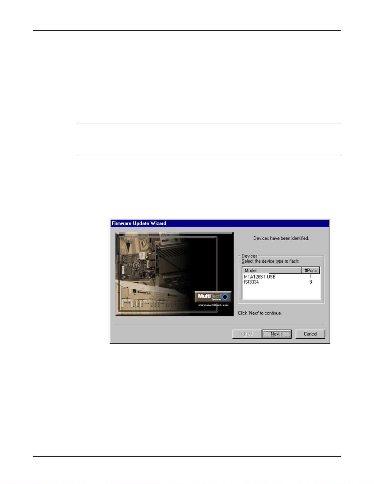
MultiModem ISDN User Guide
Upgrading the MTA128ST-USB with FlashWizard
The MTA128ST-USB has a flash PROM, which contains firmware code for the hardware. At v arious
times, Multi-Tech may add enhancements and/or fixes to the firmware. The flash technology used in
the MT A128ST-USB lets you load these upgrades into the PROM through the MTA128ST -USB’ s USB
port.
Using FlashWizard to Upgrade Firmware
1. Download the Flash Wizard utility and the ne w .HEX file from the Multi-Tech FTP site or MultiTech’ s web site .
Note: Y ou must place the .HEX file in the same directory where the Flash Wizard e x ecutab le is
located. The utility automatically senses the devices on the ports of your PC and finds the .Hex file
which is compatible with the MTA128ST -USB . If no .He x files are f ound in the directory where
Flash Wizard program is located, the utility e xits with an error .
2 . Launch the Flash Wizard utility (e.g. double-clic k on the FlashWiz.e x e file from Explorer , enter the
file name at the DOS prompt, etc.)
3. The Firmware Update Wizard dialog bo x is displa y ed indicating that it is identifying devices (this
may take up to 20 seconds).
4. Once devices hav e been identified the Firmware Update Wizar d dialog box indicating that
devices have been identified displays.
Select the device(s) you want to flash and then click Next >.
5. The Firmware Update Wizar d dialog box displays asking y ou to select the ports and hex file to
update. Once you have made the appropriate selections, click Next>.
94
6. The Firmware Update Wizard dialog box displays indicating that your devices are being
upgraded. Once finished, click Next >.
7. The Firmware Update Wizard dialog bo x is displa yed indicating the results of the update (e .g., 8
of 8 devices were updated successfully). Click Finish.
The Update Hardware Wizard completes the update process and disappears from y our screen.
Page 95

Appendixes
Page 96

MultiVOIP 200 User Guide
Appendix A: Regulatory Compliance
Class B Statement
FCC Part 15
This equipment has been tested and found to comply with the limits for a Class B digital device,
pursuant to Part 15 of the FCC Rules. These limits are designed to provide reasonable protection
against harmful interference in a residential installation. This equipment generates , uses and can
radiate radio frequency energy and, if not installed and used in accordance with the instructions, may
cause harmful interference to radio communications. Howe ver , there is no guarantee that interf erence
will not occur in a particular installation. If this equipment does cause harmful interference to radio or
television reception, which can be determined by turning the equipment off and on, the user is
encouraged to try to correct the interference by one or more of the following measures:
• Reorient or relocate the receiving antenna.
• Increase the separation between the equipment and receiver.
• Connect the equipment into an outlet on a circuit different from that to which the receiver is
connected.
• Consult the dealer or an experienced radio/TV technician for help.
This device complies with P art 15 of the FCC rules.
Operation is subject to the following two conditions:
(1 ) This device may not cause harmful interference.
(2 ) This device must accept any interference that may cause undesired operation.
Warning: Changes or modifications to this unit not e xpressly approv ed by the party responsible for
compliance could void the user’ s authority to operate the equipment.
Industry Canada
This Class B digital apparatus meets all requirements of the Canadian Interference-Causing
Equipment Regulations.
Cet appareil numerique de la classe B respecte toutes les exigences du Reglement sur le materiel
brouilleur du Canada.
EMC, Safety, and Terminal Directive Compliance
The CE mark is affixed to this product to confirm compliance with the following European Community
Directives:
Council Directive 89/336/EEC of 3 May 1989 on the approximation of the laws of Member States
relating to electromagnetic compatibility;
96
and
Council Directive 73/23/EEC of 19 February 1973 on the harmonization of the laws of Member States
relating to electrical equipment designed for use within certain voltage
limits;
and
Council Directive 98/13/EC of 12 March 1998 on the approximation of the laws of the Member States
concerning telecommunications terminal and satellite earth station equipment.
Page 97

Appendix B: Configuration Profiles
Quick Setup Factory Profiles
For quick setup, the MTA128ST-USB includes six Quick Setup Factory Profiles, each of which is
configured for a specific type of port operation. Y ou can load a Quic k Setup Factory Profile into active
memory by using the command
wish, you can then customize the profile and store it, using the &W command, so that it loads
automatically when the MT A128ST-USB is turned on or reset. These profiles are stored in permanent
memory and are not user-configurable as such.
&Fn,
in which n is the number of the profile you wish to load. If you
Appendixes
&F0
&F1
&F2
&F3
&F4
Note: The &F1 command will return an error when used with build MT128ST -USB-RC .
Profile 0—Modem-like operation (default)
Profile 1—V .110 async oper ation
Profile 2—V .120 async oper ation
Profile 3—X.75 async operation
Profile 4—ML-PPP async operation
Quick Setup Example
The following procedure assumes that you want to load, modify, and store Quick Setup Factory Profile
2 as your default configuration.
1. Select the profile closest to the requirements of your application, in this case— Quick Setup
Factory Profile 2.
2. In terminal mode, type
USB’s activ e memory.
3. Enter any additional AT commands that y ou need to customize the selected profile to your
application (see Chapter 4,
4. Type
AT&W0
and press ENTER to save your customized port configuration.
AT&F2
and press ENTER. Quick Setup Profile 2 loads into the MTA128ST-
A T Commands , S-Registers, and Result Codes
).
5. Your customized profile now loads automatically whenever the MTA128ST -USB is turned on or
reset.
Profile 0 (&F0)— Modem-Like Asynchronous Operation
AT CO MM AN D DESCRIPTION
&C 1 DCD functions normally
$D 0 Disable persistent DTR dialing
&D1 Hang up when DTR drops
E1 Enable command mode echo
&E4 Enable hardware flow control
&E6 Discard XON/XOFF characters
&E13 Enable pacing
#X0 Disable Sending Multiple Xoff Characters
&J0 Disable Automatic Channel Bundling
%E1 Enable +++ escape method
%E4 No OK response to +++ or <break> escape
&R 1 CTS always high
97
Page 98

MultiVOIP 200 User Guide
S0=1 Answer after 1 ring
S2=43 Set escape character to + (ASCII 43)
S3=13 Set carriage return character to CR (ASCII 13)
S4=10 Set line feed character to LF (ASCII 10)
S5=8 Set backspace character to BS (ASCII 8)
S7=45 Wait 45 seconds for connection before aborting
S10=20 Set DCD drop time to 700 ms
S25=5 Set DTR detect time to 500 ms
S32=20 Set escape sequence guard time to 2 seconds
S34=2 Set maximum escape sequence character length
S50=1 Caller Line ID enabled
S52=1 Auto-Protocol Detection enabled
S53=2048 Maximum X.75 buffer size is 2048 characters
&S1 DSR follows DCD
V1 Select verbose messages
!Z=x The data protocol is not modified
Profile 1 (&F1)— V.110 Asynchronous Operation*
* The MTA128ST -USB is manuf actured in two b uilds. To determine the build of your terminal
adapter (T A), issue the ATI2 command in a terminal window. If the TA responds to the command
with MTA128ST-USB, then it supports V.110. If your TA resonds to the A TI2 command with
MTA128ST-USB-RC, V.110 support is not availab le.
AT CO MM AN D DESCRIPTION
&C 1 DCD functions normally
$D 0 Disable persistent DTR dialing
&D1 Hang up when DTR drops
E1 Enable command mode echo
&E4 Enable hardware flow control
&E6 Discard XON/XOFF characters
&E13 Enable pacing
#X0 Disable Sending Multiple Xoff Characters
&J0 Disable Automatic Channel Bundling
%E1 Enable +++ escape method
%E4 No OK response to +++ or <break> escape
&R 1 CTS always high
S0=1 Answer after 1 ring
S2=43 Set escape character to + (ASCII 43)
S3=13 Set carriage return character to CR (ASCII 13)
S4=10 Set line feed character to LF (ASCII 10)
S5=8 Set backspace character to BS (ASCII 8)
S7=45 Wait 45 seconds for connection before aborting
S10=20 Set DCD drop time to 700 ms
S25=5 Set DTR detect time to 500 ms
S32=20 Set escape sequence guard time to 2 seconds
S34=2 Set maximum escape sequence character length
S50=1 Caller Line ID enabled
S52=1 Auto-Protocol Detection enabled
98
Page 99

S53=2048 Maximum X.75 buffer size is 2048 characters
&S1 DSR follows DCD
V1 Select verbose messages
!Z=6 Enable V.110 data protocol
Profile 2 (&F2)— V.120 Asynchronous Operation
AT CO MM AN D DESCRIPTION
&C 1 DCD functions normally
$D 0 Disable persistent DTR dialing
&D1 Hang up when DTR drops
E1 Enable command mode echo
&E4 Enable hardware flow control
&E6 Discard XON/XOFF characters
&E13 Enable pacing
#X0 Disable Sending Multiple Xoff Characters
&J0 Disable Automatic Channel Bundling
%E1 Enable +++ escape method
%E4 No OK response to +++ or <break> escape
&R 1 CTS always high
S0=1 Answer after 1 ring
S2=43 Set escape character to + (ASCII 43)
S3=13 Set carriage return character to CR (ASCII 13)
S4=10 Set line feed character to LF (ASCII 10)
S5=8 Set backspace character to BS (ASCII 8)
S7=45 Wait 45 seconds for connection before aborting
S10=20 Set DCD drop time to 700 ms
S25=5 Set DTR detect time to 500 ms
S32=20 Set escape sequence guard time to 2 seconds
S34=2 Set maximum escape sequence character length
S50=1 Caller Line ID enabled
S52=1 Auto-Protocol Detection enabled
S53=2048 Maximum X.75 buffer size is 2048 characters
&S1 DSR follows DCD
V1 Select verbose messages
!Z=5 Enable V.120 data protocol
Appendixes
Profile 3 (&F3)— X.75 Asynchronous Operation
AT CO MM AN D DESCRIPTION
&C 1 DCD functions normally
$D 0 Disable persistent DTR dialing
&D1 Hang up when DTR drops
E1 Enable command mode echo
&E4 Enable hardware flow control
&E6 Discard XON/XOFF characters
&E13 Enable pacing
#X0 Disable Sending Multiple Xoff Characters
&J0 Disable Automatic Channel Bundling
%E1 Enable +++ escape method
%E4 No OK response to +++ or <break> escape
&R 1 CTS always high
99
Page 100

MultiVOIP 200 User Guide
S0=1 Answer after 1 ring
S2=43 Set escape character to + (ASCII 43)
S3=13 Set carriage return character to CR (ASCII 13)
S4=10 Set line feed character to LF (ASCII 10)
S5=8 Set backspace character to BS (ASCII 8)
S7=45 Wait 45 seconds for connection before aborting
S10=20 Set DCD drop time to 700 ms
S25=5 Set DTR detect time to 500 ms
S32=20 Set escape sequence guard time to 2 seconds
S34=2 Set maximum escape sequence character length
S50=1 Caller Line ID enabled
S52=1 Auto-Protocol Detection enabled
S53=2048 Maximum X.75 buffer size is 2048 characters
&S1 DSR follows DCD
V1 Select verbose messages
!Z=12 Enable X.75 data protocol
Profile 4 (&F4)— ML-PPP Asynchronous Operation
AT CO MM AN D DESCRIPTION
&C 1 DCD functions normally
$D 0 Disable persistent DTR dialing
&D1 Hang up when DTR drops
E1 Enable command mode echo
&E4 Enable hardware flow control
&E6 Discard XON/XOFF characters
&E13 Enable pacing
#X0 Disable Sending Multiple Xoff Characters
&J0 Disable Automatic Channel Bundling
%E1 Enable +++ escape method
%E4 No OK response to +++ or <break> escape
&R 1 CTS always high
S0=1 Answer after 1 ring
S2=43 Set escape character to + (ASCII 43)
S3=13 Set carriage return character to CR (ASCII 13)
S4=10 Set line feed character to LF (ASCII 10)
S5=8 Set backspace character to BS (ASCII 8)
S7=45 Wait 45 seconds for connection before aborting
S10=20 Set DCD drop time to 700 ms
S25=5 Set DTR detect time to 500 ms
S32=20 Set escape sequence guard time to 2 seconds
S34=2 Set maximum escape sequence character length
S50=1 Caller Line ID enabled
S52=1 Auto-Protocol Detection enabled
S53=2048 Maximum X.75 buffer size 2048 is characters
&S1 DSR follows DCD
V1 Select verbose messages
!Z=9 Enable MLPPP data protocol
100
 Loading...