

Page 1

MT5634ZBA-DID
Data/Fax/DID Modem
User Guide
Page 2

User Guide
Product Number S000234A Revision A
MultiModemDID (MT5634ZBA-DID)
Copyright
Copyright © 2002 by Multi-Tech Systems, Inc.
All rights reserved. This publication may not be reproduced, in whole or in part, without prior expressed
written permission from Multi-Tech Systems, Inc.
Multi-Tech Systems, Inc. makes no representations or warranties with respect to the contents hereof and
specifically disclaims any implied warranties of merchantability or fitness for any particular purpose. Furthermore, Multi-Tech Systems, Inc. reserves the right to revise this publication and to make changes in
the content hereof without obligation of Multi-Tech Systems, Inc. to notify any person or organization of
such revisions or changes.
Record of Revisions
Revision Date Description
A 09/18/02 Supports V.92. Initial release of manual for publication on CD.
Trademarks
MultiModemZBA, Multi-Tech, and the Multi-Tech logo are trademarks of Multi-Tech Systems, Inc.
Adobe and Acrobat are trademarks of Adobe Systems Incorporated. MNP is a trademark of Microcom,
Inc. Microsoft, Windows, Windows 95, Windows 98, Windows Me, Windows NT, Windows 2000, and
Windows XP are either registered trademarks or trademarks of Microsoft Corporation in the United States
and/or other countries. All other brand and product names mentioned in this publication are trademarks
or registered trademarks of their respective companies.
Patents
This device is covered by one or more of the following patents: 6,031,867; 6,012,113; 6,009,082;
5,905,794; 5,864,560; 5,815,567; 5,815,503; 5,812,534; 5,809,068; 5,790,532; 5,764,628; 5,764,627;
5,754,589; D394,250; 5,724,356; 5,673,268; 5,673,257; 5,644,594; 5,628,030; 5,619,508; 5,617,423;
5,600,649; 5,592,586; 5,577,041; 5,574,725; D374,222; 5,559,793; 5,546,448; 5,546,395; 5,535,204;
5,500,859; 5,471,470; 5,463,616; 5,453,986; 5,452,289; 5,450,425; D361,764; D355,658; D355,653;
D353,598; D353,144; 5,355,365; 5,309,562; 5,301,274. Other patents pending.
World Headquarters
Multi-Tech Systems, Inc.
2205 Woodale Drive
Mounds View, MN 55112
U.S.A
Telephone (763) 785-3500 or (800) 328-9717
Fax (763) 785-9874
Technical Support (800) 972-2439
Internet
http://www.multitech.com
Page 3

MultiModemDID User Guide
Contents
Table of Contents
Chapter 1 - Introduction and Description......................................................................... 5
Introduction........................................................................................................... 5
Features ............................................................................................................... 5
We Supply ............................................................................................................6
Safety ................................................................................................................... 6
Chapter 2 - Installation .................................................................................................... 7
Step 1: Assemble the Modem .............................................................................. 7
Step 2: Connect the Modem to Your System ....................................................... 7
Step 3: Install the Modem Driver .......................................................................... 8
Removing Your Old Modem from Windows.......................................................... 8
Chapter 3 – Operation................................................................................................... 10
Front Panel of the MultiModemDID Modem ....................................................... 10
DID Operation..................................................................................................... 11
V.92 Operation ................................................................................................... 11
Connecting to the Internet .................................................................................. 12
Dial-Up Networking............................................................................................. 12
Chapter 4 - AT Commands, S -Registers, and Result Codes ....................................... 13
AT Commands.................................................................................................... 14
V.92 Commands ................................................................................................. 28
Other Commands ............................................................................................... 30
DID Commands .................................................................................................. 32
MT5634ZBA-DID Initialization Recommendations ............................................. 32
About the Busy-Out Features and Functions ..................................................... 33
S-Registers ......................................................................................................... 36
Result Codes ...................................................................................................... 39
Chapter 5 - Remote Configuration ................................................................................ 41
Basic Procedure ................................................................................................. 41
Setup .................................................................................................................. 41
3
Page 4

MultiModemDID User Guide
Contents
Chapter 6 - Troubleshooting.......................................................................................... 43
None of the Indicators Light................................................................................ 43
The Modem Does Not Respond to Commands.................................................. 43
The Modem Dials But Cannot Connect .............................................................. 44
The Modem Disconnects While Online .............................................................. 45
The Modem Cannot Connect When Answering ................................................. 45
The Modem Doesn’t Work with Caller ID............................................................ 45
Fax and Data Software Can’t Run at the Same Time ........................................ 45
DID Troubleshooting........................................................................................... 46
Appendix A – Regulatory Compliance........................................................................... 47
FCC Part 68 Telecom ......................................................................................... 47
FCC Part 15........................................................................................................ 48
Fax Branding Statement ..................................................................................... 48
Canadian Limitations Notice ............................................................................... 48
Industry Canada .................................................................................................48
Appendix B – Technical Specifications ......................................................................... 49
Appendix C - Warranty and Repairs ............................................................................. 50
Appendix D - Upgrading the Modem’s Firmware .......................................................... 52
Appendix E - Installing a Modem Under Linux .............................................................. 54
Introduction......................................................................................................... 54
Standard Linux Serial Port Definitions ................................................................ 54
Installation .......................................................................................................... 54
Setup .................................................................................................................. 54
Appendix F - Technical Support .................................................................................... 56
Index .................................................................................................... 57
4
Page 5

MultiModemDID User Guide
Chapter 1 - Introduction and Description
Chapter 1 - Introduction and Description
Welcome to the world of data communications. You have acquired one of the finest intelligent data and
fax modems available today from one of America’s oldest and most respected modem manufacturers:
Multi-Tech Systems, Inc. This User Guide will help you install, configure, test, and use your modem.
Introduction
The MultiModemDID combines Direct Inward Dial (DID) with Super G3 V.34/33.6K bps fax and V.92 data
modes of operation. Direct Inward Dial allows the user to use a block of telephone numbers larger than
the number of physical telephone lines for direct dialing to extensions. When combining DID with inbound
fax calls to a fax server, each user on the fax server can have faxes automatically routed to them at their
client computer desktop.
DID fax routing assigns a unique fax number for every network user or network device (such as a
printer). Senders simply dial a typical telephone number - no special procedures are required. The fax
server automatically delivers the incoming fax to the user over the local area network.
Users get improved efficiency and security, since their faxes are delivered by the network fax server to
the client desktop as soon as they are received. Time-wasting trips to the fax machine are eliminated and
employees are more productive. In addition, DID offers a higher degree of security for both the sender
and the recipient since faxes are not left unattended at a central fax machine.
The MT5634ZBA-DID utilizes Super G3 V.34 fax speeds of 33.6K bps. Now, computer-based fax servers
can achieve the Super G3 speeds found in dedicated fax machines. The MT5634ZBA-DID also supports
T.31 Annex B and T.32 Annex C, which allows the higher V.34 speeds to operate with Class 1.0 and
Class 2.1 code sets. In addition, “on-the-fly” two-dimensional fax data compression plus support for error
correction mode (ECM) increase the performance of the MT5634ZBA-DID to levels previously only found
in expensive fax boards and dedicated fax machines.
To implement DID fax routing you must purchase fax server application software that supports Multi-Tech
DID commands and DID routing, and obtain an analog DID trunk line which supports the inbound fax
calls and a regular loop-start line for outbound fax transmission.
Features
· One Direct Inward Dial (DID) port
· Super G3 V.34/33.6K bps fax communication
· T.31 Annex B Class 1.0 and T.32 Annex C Class 2.1 fax commands
· Error Correction Mode (ECM) provides fast and reliable fax transmissions
· Supports Wink-start, Immediate-start and Delay dial service types
· V.92/56K data mode
· V.44 compression improves data throughput rates
· V.42 error correction
· Flash memory for easy updates
Plug and Play operation.
Interactive automatic dialing and command mode configuration.
In standard mode, you can store up to four command lines or telephone numbers of up to 40
characters each in the modems’ nonvolatile memory.
Pulse- or tone-dials and recognizes dial tones and busy signals for reliable call-progress detection.
Detects AT&T calling card tones.
Caller ID.
Remote configuration.
Incorporates self-resetting lightning protection.
5
Page 6

MultiModemDID User Guide
Chapter 1 - Introduction and Description
We Supply
• An MT5634ZBA-DID modem
• A set of four self-adhesive plastic feet
• A power supply
• A 9-pin to 9-pin serial cable
• Two RJ-11 telephone cables
• A printed Quick Start Guide
• A CD containing modem drivers, a User Guide, and Adobe Acrobat Reader.
You Supply
• A computer with an available serial port
• A nearby AC power outlet
• A nearby phone line jack
• A nearby analog DID trunk line with a block of associated DID telephone numbers
Safety
1. Use this product only with UL and cUL listed computers.
2. To reduce the risk of fire, use only 26 AWG (.41mm) or larger telephone wiring.
3. Never install telephone wiring during a lightning storm.
4. Never install a telephone jack in wet locations unless the jack is specifically designed for wet
locations.
5. Never touch uninsulated telephone wires or terminals unless the telephone line has been
disconnected at the network interface.
6. Use caution when installing or modifying telephone lines.
7. Avoid using a telephone during an electrical storm. There is a risk of electrical shock from
lightning.
8. Do not use a telephone in the vicinity of a gas leak.
6
Page 7
MultiModemDID User Guide
Chapter 2 - Installation
Chapter 2 - Installation
Step 1: Assemble the Modem
The only assembly required is to mount the feet on the bottom of the modem. Simply peel the four selfadhesive plastic feet off the backing strip and press them into the recesses on the bottom of the modem.
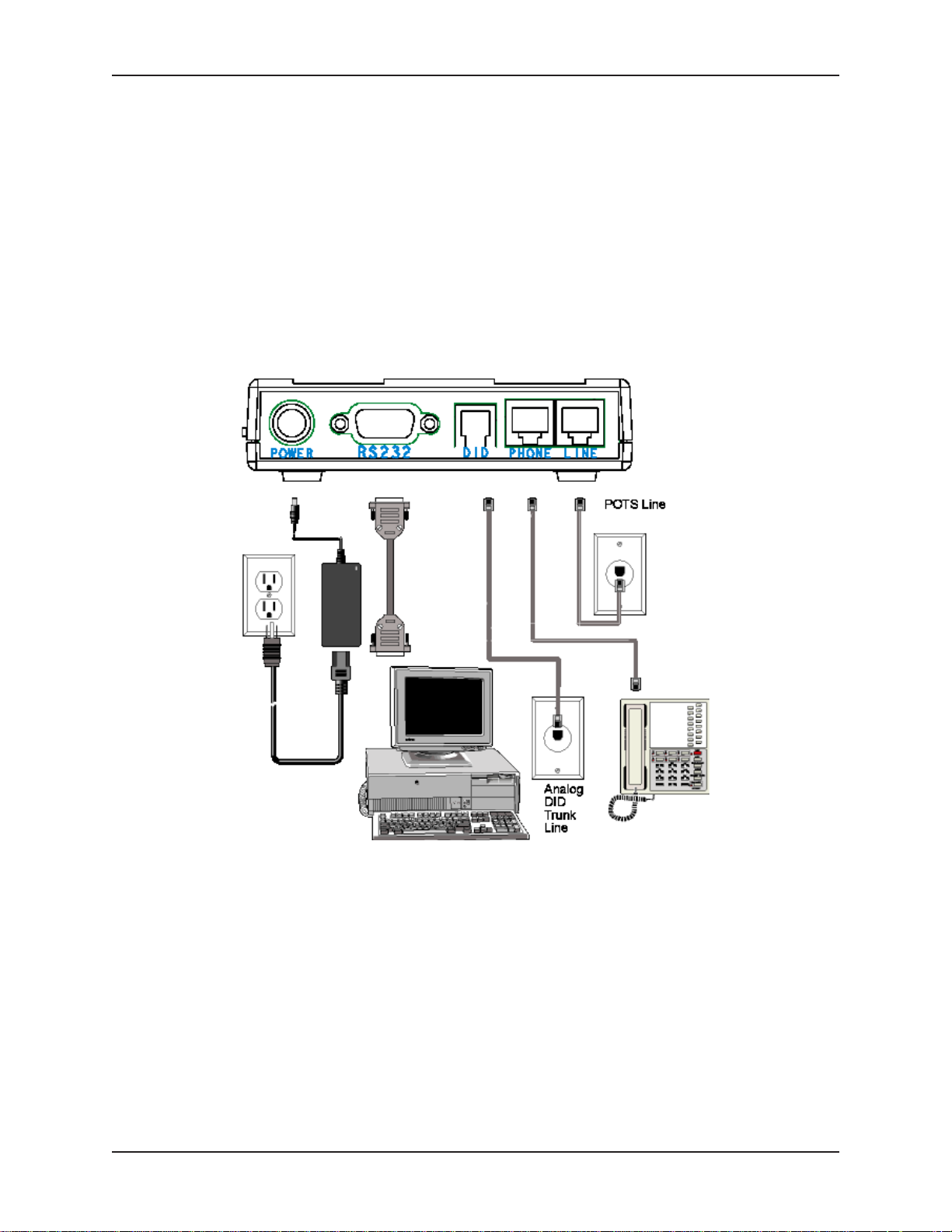
Step 2: Connect the Modem to Your System
Turn off your computer. Place the modem in a convenient location, and then connect it to your
computer’s serial port, the phone line, AC power, DID line, and your phone.
Connect the Modem to Your PC
Plug one end of the serial cable into the connector on the modem, and plug the other end into a
serial port on your computer, such as COM1 or COM2.
Connect the Modem to the Telephone Line
Plug one end of the phone cable into the modem’s LINE jack and the other end into a phone wall
jack. The phone cable is included with your modem.
Note: The LINE jack is not interchangeable with the PHONE jack. Do not plug the phone into the LINE
jack or the line cable into the PHONE jack.
7
Page 8

MultiModemDID User Guide
(Optional) Connect the Modem to the Phone
For voice-only calls, plug a phone into the modem’s PHONE jack.
Connect the Modem to the AC Power Outlet
Make sure the power is switch is OFF. Plug the DC power transformer into a power outlet or power
strip. Plug the other end into the PWR jack on the modem. The DC power transformer is included
with your modem.
CAUTION: Use only the DC power transformer supplied with the modem. Use of any other
transformer voids the warranty and can damage the modem.
Connect the Modem to the DID Line
Plug one end of the phone cable into the modem’s DID jack and the other end into an analog DID
trunk line jack. The DID Line cable is included with your modem.
CAUTION: The DID Line cable has a 4-pos RJ11 on one side and a 6-pos on the other. Never plug
the DID connector into a standard POTS Line. This may damage the modem or the central office
equipment. Use only an analog DID Line.
Power-on Test
Test the modem by turning it on (an on-off switch is located on the side panel). When you apply
power, the modem performs a diagnostic self-test. The 56 indicator lights, and if a terminal program
is running, the TR indicator also lights. If this does not happen, check that the power switch is on,
the power supply is solidly connected, and the AC outlet is live. If these measures do not work, see
the
Troubleshooting
chapter.
Chapter 2 - Installation
Step 3: Install the Modem Driver
1. Make sure your modem is connected properly, and then turn on your computer. Windows should
detect your new modem and open the Install New Modem wizard.
Note: If Windows cannot find a modem, your modem may be turned off, it may be plugged into the
wrong connector on your computer, or the serial cable may be faulty. See “None of the LEDs Light
When the Modem Is Turned On” and “The Modem Does Not Respond to Commands” in the
“Troubleshooting” chapter in the complete User Guide.
2. Insert the MT5634ZBA-DID CD into your CD-ROM drive, and then click OK.
3. Windows installs the modem driver.
4. Click Finish to exit
Removing Your Old Modem from Windows
When your new modem replaces another modem, the old modem installation remains in Windows after
you install the new modem, and the old modem is still selected in HyperTerminal and other Windows
applications. Although you can change the application connection descriptions one at a time, it is easier
to force Windows applications to use the new modem by removing the old modem from Windows.
8
Page 9

MultiModemDID User Guide
Chapter 2 - Installation
From Windows 2000, XP
1. Click Start | Settings | Control Panel.
2. Double-click the Phone and Modems icon and click on the Modems tab.
3. In the list box, select the old modem.
4. Click Remove, then click Close.
5. The next time you dial a HyperTerminal connection, it will select your new modem and ask you
to confirm the selection.
From Windows 98, Me
1. Click Start | Settings | Control Panel.
2. Double-click the Modems icon to open the Modems Properties sheet.
3. In the list box, select the old modem.
4. Click Remove, then click Close.
5. The next time you dial a HyperTerminal connection, it will select your new modem and ask you
to confirm the selection.
9
Page 10
MultiModemDID User Guide
Chapter 3 - Operation
Chapter 3 – Operation
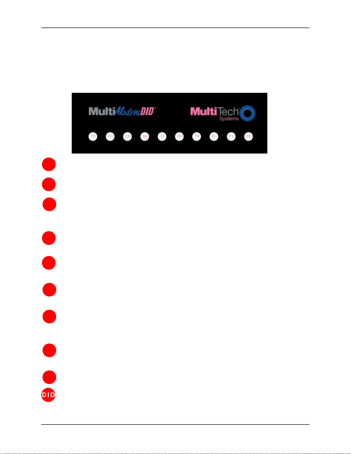
Front Panel of the MultiModemDID Modem
The MT5634ZBA-DID modem has 10 LED indicators on the front panel that provide information about
how your modem is operating: status, configuration and activity.
Transmit Data - The TD LED flashes when the modem is transmitting data to another modem.
TD
Receive Data - The RD LED flashes when the modem is receiving data from another modem.
RD
Carrier Detect - The CD LED lights when the modem detects a valid carrier signal from another
CD
modem. It is on when the modem is communicating with the other modem and off when the link is
broken.
56 - The 56 LED is a 56K mode indicator. It lights whenever the modem is set for or connects
56
using the V.90 or V.92 protocols.
33 - The 33 LED is a V.34 mode indicator. It lights whenever the modem connects using the V.34
33
protocol.
Off-Hook - The OH LED lights when the modem is off-hook, which occurs when the modem is
OH
dialing, online, or answering a call. The LED flashes when the modem pulse-dials.
Terminal Ready - The TR LED lights when a communications program is using the modem. It
TR
means the modem is ready for an outgoing or incoming call. It goes off when the communications
program disconnects the serial port. When it goes off, a connected modem will also disconnect.
Error Correction (V.42) - The EC LED lights continuously when the modem is in V.42 error
EC
correction mode, and it flashes when compression is achieved.
Fax - The FX LED lights when the modem is in fax mode.
FX
DID - The DID LED lights when there is an incoming call on the DID line.
10
Page 11

MultiModemDID User Guide
Chapter 3 - Operation
DID Operation
Direct Inward Dialing (DID) uses an analog trunk line to route several phone numbers to one line. The
MT5634ZBA-DID modem has four ports, an RS232 serial port, two RJ11 ports for connection to a POTS
line and an auxillary phone, and a 4 position RJ12 for connection to the DID analog trunk.
Note: The DID and POTS ports cannot operate simultaneously.
On a DID line the roles of the central office and the DID modem are somewhat reversed. The DID
modem must provide a DC voltage, around 48V, to the line. When there is an incoming call, the central
office will complete a loop and draw current from the DID modem.
On a standard POTS line, the central office provides the DC voltage and the user will close the loop by
lifting the handset of a phone or making a call with a standard modem.
There are two critical points about the DC voltage:
1. The central office is sensitive to the DC polarity. TiP (positive) and riNg (Negative) must be
connected to the line from the central office with the proper polarity. If not, callers will receive an
immediate busy signal or may be allowed to make a short connection but become unexpectedly
disconnected after a short time.
2. The DC voltage should be applied by the modem at all times, even when not in use. Occasionally,
the central office will check the line; and, if a voltage is not sensed, the line will be put out of
service. A call to the phone company will be required to get the line back in service.
The DID modem may use line reversals to signal the central office to send digit information or open the
channel to the calling party depending on the start protocol of the DID line. The central office will forward
several of the last digits of the incoming call to the DID modem through one of three formats, DTMF, MF,
or pulse signaling.
V.92 Operation
Because the V.92 protocol is new and still largely unsupported by central servers, some features are
disabled by default in the initial release of the MT5634ZBA-DID modem. This section describes the status
of the V.92 features in the initial release. Please note that the V.92 special features require connection to
a V.92-capable server.
General. The V.92 protocol is enabled by default. If the MultiModemZBA-DID detects another
V.92 modem during the handshake phase, they will connect in V.92 mode; otherwise, they will
connect in V.90 mode or the highest mutually acceptable mode. The AT command that controls
this is +MS=.
Commands. AT commands specific to the V.92 protocol and the new V.44 compression protocol
begin with the plus character (+). These commands are in this manual. Also, the S109 register
has been modified to support V.92.
PCM Upstream. PCM Upstream is disabled by default. To upload files at speeds above 33.6
kbps, you must enable PCM Upstream using the command +PIG=1. Please note that this requires
connection to a V.92-capable server. Also, please note that since upload speeds are affected by
line conditions, meeting the previous requirements cannot guarantee speeds above 33.6 kbps.
Quick Connect. Quick Connect, which shortens the handshake time with another V.92 modem, is
disabled by default. To enable it, use the command +PQC=0. Quick Connect speeds connect
times by skipping the line test during the handshake and using the configuration from the last data
connection. Quick Connect works best when line conditions are consistent from call to call. If line
conditions are variable, enabling Quick Connect can actually increase the connect time slightly.
Modem on Hold (is not available at this time).
11
Page 12

MultiModemDID User Guide
Chapter 3 - Operation
Connecting to the Internet
Your Multi-Tech modem is your gateway to the Internet and the World Wide Web. To access the Internet
and Web via your modem, you must establish a dial-up account with an Internet service provider (ISP).
To locate an ISP near you, look in a local directory or computer publication. Your ISP should provide you
with the following information:
User name (also called user ID)
Password
Access number (the number you call to connect to the server)
Host name and/or domain name
Domain Name Server (DNS) server address
If, besides the Web, you use the Internet for e-mail and newsgroups, your ISP should also provide you
with the following information:
E-mail or POP mail address
POP server address
Mail or SMTP address
News or NNT server address
Dial-Up Networking
Before you can connect to the Internet, you must set up a remote-node client program on your computer.
The Windows version is called Dial-Up Networking. Dial-Up Networking establishes your connection to
the ISP’s server, which is the shared computer that manages calls from clients (your computer) to the
Internet. Most, if not all, Windows browsers start Dial-Up Networking automatically when you open them.
For instructions on how to set up Dial-Up Networking, consult your ISP or your operating system’s online
help or printed documentation. Many ISPs include, as part of their service, a program that will install and
configure Dial-Up Networking automatically for you.
12
Page 13

MultiModemDID User Guide
Chapter 4 - AT Commands, S-Registers, Result Codes
Chapter 4 - AT Commands, S -Registers,
and Result Codes
AT commands are used to control the operation of your modem. They are so called because each
command must be preceded by the characters AT to get the ATtention of the modem.
AT commands can be issued only when the modem is in command mode or online command mode. The
modem is in
mode
whenever it is connected to another modem and ready to exchange data.
is a temporary state in which you can issue commands to the modem while connected to another
modem. To put the modem into online command mode from data mode, you must issue an
sequence
the modem. To return to data mode from online command mode, you must issue the command ATO.
To send AT commands to the modem you must use a communications program, such as HyperTerminal
or the PhoneTools communications program included with your modem. You can issue commands to the
modem either directly, by typing them in the terminal window of the communications program, or
indirectly, by configuring the operating system or communications program to send the commands
automatically. Fortunately, communications programs make daily operation of modems effortless by
hiding the commands from the user. Most users, therefore, need to use AT commands only when
reconfiguring the modem, e.g., to turn autoanswer on or off.
The format for entering an AT command is ATXn, where X is the command and n is the value for the
command, sometimes called the command
you can omit it from the command; thus, AT&W is equivalent to AT&W0. Most commands have a
value, which is the value that is set at the factory. The default values are shown in the “AT Commands”
section, which begins on the next page.
You must press ENTER to send the command to the modem. Any time the modem receives a command, it
sends a response known as a
CONNECT
For a table of valid result codes, see “Result Codes” at the end of this chapter.
You can issue several commands in one line, in what is called a command
begins with AT and ends when you press ENTER. Spaces to separate the commands are optional; they
are ignored by the command interpreter. The most familiar command string is the
which is used to configure the modem when it is turned on or reset, or when your communications
software calls another modem.
command mode
(+++) followed immediately by the AT characters and the command, e.g., +++ATH to hang up
messages that the modem sends to the computer when it is connecting to another modem.
whenever it is not connected to another modem. The modem is in
Online command mode
escape
result code
parameter
. The most common result codes are OK,
. The value is always a number. If the value is zero,
ERROR
string
. The command string
initialization string
, and the
data
default
,
13
Page 14

MultiModemDID User Guide
AT Commands
Command: AT Attention Code Values: n/a Description: The attention code precedes all command lines except A/ and
Chapter 4 - AT Commands, S-Registers, Result Codes
the escape sequence.
Command: E
NTER Key
Values: n/a
Description: Press the E
NTER or RETURN key to execute most commands.
Command: A Answer
Values: n/a
Description: Answers an incoming call before the final ring.
Command: A/ Repeat Last Command
Values: n/a
Description: Repeats the last command string. Do not precede this
Command: B
Values:
command with AT. Do not press E
n
Communication Standard Setting
n
= 0–3, 15, 16
NTER to execute.
Default: 1 and 16
Description: B0 Select ITU-T V.22 mode when modem is at 1200 bps.
B1 Select Bell 212A when modem is at 1200 bps.
B2 Deselect V.23 reverse channel (same as B3).
B3 Deselect V.23 reverse channel (same as B2).
B15 Select V.21 when the modem is at 300 bps.
B16 Select Bell 103J when the modem is at 300 bps.
Command: D
Values:
s
Dial
s
= dial string (phone number and dial modifiers)
Default: none
Description: Dial telephone number s, where s may up to 40 characters long
and include the 0–9, *, #, A, B, C, and D characters, and the L,
P, T, W, S, comma (,), semicolon (;), !, @, ^ and $ dial string
modifiers.
Dial string modifiers:
L Redial last number. (Must be placed immediately after ATD.)
P Select pulse-dialing until a T is encountered. Affects current
and subsequent dialing.
T Select tone-dialing until a P is encountered. Affects current
and subsequent dialing.
W Wait for a new dial tone before continuing to dial. (X2, X4,
X5, X6, or X7 must be selected.)
, Pause during dialing for time set in register S8.
; Return to command mode after dialing. Place at end of dial
string.
! Hook flash. Causes the modem to go on-hook for one-half
second, then off-hook again.
14
Page 15

MultiModemDID User Guide
Chapter 4 - AT Commands, S-Registers, Result Codes
@ Wait for quiet answer. Causes modem to wait for a ring
back, then 5 seconds of silence, before processing next
part of command. If silence is not detected, the modem
returns a NO ANSWER code.
^ Disable data calling tone transmission.
$ Detect AT&T call card “bong” tone. The character should
follow the phone number and precede the user’s call card
number: ATDT1028806127853500
$123456789.
Command: DS=
Values:
Default: none
Description: Dials a number previously stored in directory number y by the
Command: E
Values:
Default: 1
Description: E0 Does not echo keyboard input to the terminal.
Command: F
Values:
Default: 1
Description: F0 Enables online data character echo. (Not supported.)
Command: H
Values:
Default: 0
Description: H0 Goes on-hook (hangs up).
n
Dial Stored Telephone Number
n
= 0, 1, 2
&Zn=x
n
Echo Command Mode Characters
n
E1 Does echo keyboard input to the terminal.
n
Echo Online Data Characters
n =
F1 Disables online data character echo (included for backward
compatibility with some software).
n
Hook Control
n
H1 Goes off-hook (makes the phone line busy).
command. Example: ATDS=3.
= 0 or 1
0, 1
= 0 or 1
Command: I
Values:
Default: None
Description: I0 Displays default speed and controller firmware version.
n
Information Request
n
= 0–5, 9, 11
I1 Calculates and displays ROM checksum (e.g.,
I2 Checks ROM and verifies the checksum, displaying
ROR
.
I3 Displays default speed and controller firmware version.
I4 Displays firmware version for data pump (e.g., 17).
I5 Displays the board ID: software version, hardware version, and
the country ID in hexadecimal format (e.g.,
I9 Displays the country code in decimal format (e.g.,
I11 Displays diagnostic information for the last modem connection,
such as DSP and firmware version, link type, line speed, serial
speed, type of error correction/data compression, number of
past retrains, etc.
B399
).
OK
s0503a01V, 0, 34
52
).
or
ER-
).
15
Page 16

MultiModemDID User Guide
Chapter 4 - AT Commands, S-Registers, Result Codes
Command: M
Values:
Default: 1
Description: M0 Speaker always off.
Command: N
Values:
Default: 1
Description: N0 Modem performs handshake only at communication standard
Command: O
Values: 0, 1, 3
Default: None
Description: O0 Exits online command mode and returns to data mode (see
n
Monitor Speaker Mode
n
= 0, 1, 2, or 3
M1 Speaker on until carrier signal detected.
M2 Speaker always on when modem is off-hook.
M3 Speaker on until carrier is detected, except while dialing.
n
Modulation Handshake
n
= 0 or 1
specified by S37 and the B command.
N1 Modem begins handshake at communication standard
specified by S37 and the B command. During handshake,
fallback to a lower speed can occur.
n
Return Online to Data Mode
+++AT<CR> escape sequence ).
O1 Issues a retrain and returns to online data mode.
O3 Issues a rate renegotiation and returns to data mode.
Command: P Pulse Dialing
Values: P, T
Default: T
Description: Configures the modem for pulse (non-touch-tone) dialing.
Dialed digits are pulsed until a T command or dial modifier is
received.
Command: Q
Values:
Default: 0
Description: Q0 Enables result codes.
Command: Sr=nSet Register Value
Values:
Default: None
Description: Sets the value of register Sr to the value of n, where n is
Command: Sr? Read Register Value
Values:
Default: None
Description: Reads the value of register Sr and displays it in 3-digit decimal
n
Result Codes Enable/Disable
n
= 0, 1
Q1 Disables result codes.
r
= S-register number; n varies
entered in decimal format. Example: S0=1.
r
= S-register number
form. For example, S2? gives the response
043
.
16
Page 17

MultiModemDID User Guide
Command: T Tone Dialing
Values: P, T
Default: T
Description: Configures the modem for DTMF (touch-tone) dialing. Dialed
Chapter 4 - AT Commands, S-Registers, Result Codes
digits are tone dialed until a P command or dial modifier is
received.
Command: V
Values:
Default: 1
Description: V0 Displays result codes as digits (terse response).
Command: W
Values:
Default: 2
Description: W0
Command: X
Values:
Default: 4
Description: X0 Basic result codes (
n
Result Code Format
n
= 0 or 1
V1 Displays result codes as words (verbose response).
n
Result Code Options
n
= 0, 1, 2
CONNECT
protocol result codes.
W1
CONNECT
protocol result codes.
W2
CONNECT
result codes.
n
Result Code Selection
n
= 0–7
tone or busy signal.
X1 Extended result codes (
not look for dial tone or busy signal.
X2 Extended result codes with
busy signal.
X3 Extended result codes with
X4 Extended result codes with
X5 Extended result codes with
X6 Extended result codes with
X7 Basic result codes with
result code reports serial port speed, disables
result code reports serial port speed, enables
result code reports line speed, enables protocol
e.g., CONNECT
); does not look for dial
e.g., CONNECT 46000 V42bis
NO DIALTONE
BUSY
; does not look for dial tone.
NO DIALTONE
NO DIALTONE
NO DIALTONE
NO DIALTONE
; does not look for
and
and
and
and
BUSY
BUSY
BUSY
BUSY
.
); does
.
.
.
Command: Z
Values:
Default: None
Description: Z0 Resets modem to profile saved by the last &W command.
Command: &CnData Carrier Detect (DCD) Control
Values:
Default: 1
Description: &C0 Forces the DCD circuit to be always high.
n
Modem Reset
n
= 0 or 1
Z1 Same as Z0.
n
= 0, 1, or 2
&C1 DCD goes high when the remote modem’s carrier signal is
detected, and goes low when the carrier signal is not detected.
&C2 DCD drops on disconnect for time set by S18, then goes high
again (for some PBX phone systems).
17
Page 18

MultiModemDID User Guide
Command: &DnData Terminal Ready (DTR) Control
Values:
Default: 2
Description: &D0 Modem ignores the true status of the DTR signal and responds
Chapter 4 - AT Commands, S-Registers, Result Codes
n
= 0, 1, 2, or 3
as if it is always on.
&D1 If DTR drops while in online data mode, the modem enters
OK
command mode, issues an
&D2 If DTR drops while in online data mode, the modem hangs up.
If the signal is not present, the modem will not answer or dial.
&D3 If DTR drops, the modem hangs up and resets as if an ATZ
command were issued.
, and remains connected.
Command: &E
Values:
Default: 12
Description: &E12 Disables XON/XOFF pacing.
Note: &E13 has no effect if hardware control (&K3) is selected.
Command: &F
Values:
Default: None
Description: &F0 Loads factory settings as active configuration.
Note: See also the Z command.
Command: &GnV.22bis Guard Tone Control
Values:
Default: 0
Description: &G0 Disables guard tone.
Note: The &G command is not used in North America.
Command: &KnFlow Control Selection
Values:
Defaults: 3
Description: &K0 Disables flow control.
n
XON/XOFF Pacing Control
n
= 12 or 13
&E13 Enables XON/XOFF pacing. (&K4 must also be set.)
n
Load Factory Settings
n
= 0
n
= 0, 1, or 2
&G1 Sets guard tone to 550 Hz.
&G2 Sets guard tone to 1800 Hz.
n
= 0, 3, or 4
&K3 Enables CTS/RTS hardware flow control.
&K4 Enables XON/XOFF software flow control.
Command: &QnAsynchronous Communications Mode
Values:
Default: 5
Description: &Q0 Asynchronous with data buffering. Same as \N0.
n
= 0, 5, 6, 8, or 9
&Q5 Error control with data buffering. Same as \N3.
&Q6 Asynchronous with data buffering. Same as \N0.
&Q8 MNP error control mode. If MNP error control is not
established, the modem falls back according to the setting in
S36.
&Q9 V.42 or MNP error control mode. If neither error control is
established, the modem falls back according to the setting in
S36.
18
Page 19

MultiModemDID User Guide
Command: &SnData Set Ready (DSR) Control
Values:
Default: 0
Description: &S0 DSR is always high (on).
Command: &T
Values:
Default: None
Description: &T0 Abort. Stops any test in progress.
Note: To stop a test, you must use the escape sequence (+++AT) before typing
&T0.
Command: &V Display Current Settings
Values: n/a
Description: Displays the active modem settings, including the callback
Chapter 4 - AT Commands, S-Registers, Result Codes
n
= 0 or 1
&S1 DSR goes high only during a connection.
n
V.54 Test Commands
n
= 0, 1, 3 or 6
&T1 Initiates local analog loopback test.
&T3 Initiates local digital loopback test.
&T6 Initiates remote digital loopback test.
security settings if callback security is enabled. If the setup
password has been entered, it also displays the callback
security passwords.
Command: &WnStore Current Configuration
Values:
Default: 1
Description: &W0 Stores current modem settings in nonvolatile memory and
Command: &Z
Values:
Default: None
Description: Stores dialing command x in memory location y. Dial the stored
Command: \A
Values:
Default: 3
Description: \A0 64-character maximum.
n
= 0, 1
causes them to be loaded in place of the factory defaults at
power-on or following the ATZ command. See also the &F
command.
&W1 Clears user default settings from nonvolatile memory and
causes the factory defaults to be loaded at power-on or
following the ATZ command.
n=x
Store Dialing Command
n
= 0, 1, 2 (callback security disabled)
x
= Dialing command string
number using the command ATDS=n. See also the #CBS
command.
n
Select Maximum MNP Block Size
n
= 0, 1, 2, or 3
\A1 128-character maximum.
\A2 192-character maximum.
\A3 256-character maximum.
n
19
Page 20

MultiModemDID User Guide
Chapter 4 - AT Commands, S-Registers, Result Codes
Command: \B
Values:
Default: 3
Description: In non-error-correction mode only, sends a break signal of the
Command: \K
Values:
Default: 5
Description: Controls the response of the modem to a break received from
n
Transmit Break
n
= 0–9 in 100 ms units
specified length to a remote modem. Works in conjunction with
the \K command.
n
Break Control
n
= 0–5
the computer, the remote modem, or the \B command. The
response is different for each of three different states.
Data mode. The modem receives the break from the
computer:
\K0 Enters online command mode, no break sent to the remote
modem.
\K1 Clears data buffers and send break to the remote modem.
\K2 Same as \K0.
\K3 Sends break immediately to the remote modem .
\K4 Same as \K0.
\K5 Sends break to the remote modem in sequence with the
transmitted data.
Data mode. The modem receives the break from the remote
modem:
\K0 Clears data buffers and sends break to the computer.
\K1 Same as \K0.
\K2 Sends break immediately to the computer.
\K3 Same as \K2.
\K4 Sends break to the computer in sequence with the received data.
\K5 Same as \K4.
Online command mode. The modem receives a \B
command from the computer:
\K0 Clears data buffers and sends break to the remote modem.
\K1 Same as \K0.
\K2 Sends break immediately to the remote modem.
\K3 Same as \K2.
\K4 Sends break to the remote modem in sequence with the
transmitted data.
\K5 Same as \K4.
n
20
Page 21

MultiModemDID User Guide
Chapter 4 - AT Commands, S-Registers, Result Codes
Command: \N
Values:
Default: 3
Description: \N0 Non-error correction mode with data buffering (buffer mode;
Command: \QnFlow Control Selection
Values:
Default: 3
Description: \Q0 Disables flow control (same as &K0).
n
Error Correction Mode Selection
n
= 0–5, or 7
same as &Q6).
\N1 Direct mode.
\N2 MNP reliable mode. If the modem cannot make an MNP
connection, it disconnects.
\N3 V.42/MNP auto-reliable mode. The modem attempts first to
connect in V.42 error correction mode, then in MNP mode, and
finally in non-error-correction (buffer) mode with continued
operation.
\N4 V.42 reliable mode. If the modem cannot make a V.42
connection, it disconnects.
\N5 V.42, MNP, or non-error correction (same as \N3).
\N7 V.42, MNP, or non-error correction (same as \N3).
n
= 0, 1, or 3
\Q1 XON/XOFF software flow control (same as &K4).
\Q2 CTS-only flow control. Not supported.
\Q3 RTS/CTS hardware flow control (same as &K3).
Command: \T
Values:
Default: 0
Description: \Tn Sets the time (in minutes) that the modem waits after the last
Note: You can also set the inactivity timer by changing the value of S30.
Command: \V
Values:
Default: 1
Description: \V0 Disables the appending of the protocol result code to the DCE
Command: \X
Values:
Defaults: 0
Description: \X0 Modem responds to and discards XON/XOFF characters.
Command: -CnData Calling Tone
Values:
Defaults: 0
Description: -C0 Disables V.25 data calling tone to deny remote data/fax/voice
n
Inactivity Timer
n
= 0, 1–255
character is sent or received before it disconnects. A value of
zero disables the timer. Applies only in buffer mode.
n
Protocol Result Code
n
= 0, 1, or 2
speed.
\V1 Enables the appending of the protocol result code to the DCE
speed.
\V2 Same as \V1.
n
XON/XOFF Pass-Through
n
= 0 or 1
\X1 Modem responds to and passes XON/XOFF characters.
n
= 0 or 1
discrimination.
-C1 Enables V.25 data calling tone to allow remote data/fax/voice
discrimination.
21
Page 22

MultiModemDID User Guide
Command: %A Adaptive Answer Result Code Enable
Values:
Default: 0
Description: The %A command controls whether the
Chapter 4 - AT Commands, S-Registers, Result Codes
n
= 0 or 1
codes will be sent by the modem. The modem must be in fax
mode for this command to work. Also, the modem must be set
to +FAA=1, which enables the modem to distinguish between a
fax and a data call. When these commands are enabled, the
modem sends
and
FAX
some servers to select the appropriate communication program.
%A0 Disables adaptive answer result codes.
%A1 Enables adaptive answer result codes.
DATA
to the computer when it detects data tones,
when it detects fax tones. These strings are used by
DATA
and
FAX
result
Note: For descriptions of the +FAA= and other fax commands, see the Multi-Tech
Class 2.1 Developer’s Guide
Command: %B View Numbers in Blacklist
Values: n/a
Description: If blacklisting is in effect, AT%B displays the numbers for which
Command: %CnData Compression Control
Values:
Default: 1
Description: %C0 Disable sV.42bis/MNP 5 data compression.
%C1 Enables V.42bis/MNP 5 data compression.
Command: %DCnAT Command Control
Values:
Default: 0
Description: %DC0 The modem responds to AT commands.
%DC1 The modem ignores AT commands.
Note: The modem will respond to AT%DC for 10 seconds after it is turned on.
Command: %EnFallback and Fall Forward Control
Values:
Default: 2
Description: %E0 Disables fallback and fall-forward.
%E1 Enables fallback, disables fall-forward.
%E2 Enables fallback and fall-forward.
.
the last call attempted in the previous two hours failed. In
countries that do not require blacklisting, the
code appears.
n
= 0 or 1
n
= 0 or 1
n
= 0, 1, or 2
ERROR
Fax
result
Command: %HnDirect Connect Enable
Values:
Default: 0
Description: %H0 Sets callback security to normal operation.
n
= 0, 1
%H1 All callback security calls will be direct connect regardless of
whether the password or phone number has the - character.
22
Page 23

MultiModemDID User Guide
Command: %RnCisco Configuration
Values:
Default: 0
Description: %R0 Disables Cisco configuration.
Command: %SnCommand Speed Response
Values:
Default: 0
Description: %S0 Sets modem to respond to AT commands at all normal speeds.
Chapter 4 - AT Commands, S-Registers, Result Codes
n
= 0, 1
%R1 Sets E0, Q1, &D0, \N0, $SB9600, and %S1 for operation with
a Cisco router.
n
= 0, 1
%S1 AT commands accepted at 115200 bps only. AT commands at
other speeds are ignored.
Command: $D
Values:
Default: 0
Description: $D0 Disables DTR dialing.
Command: $EBnAsynchronous Word Length
Values:
Default: 0
Description: $EB0 Enables 10-bit mode.
Command: $SBnSerial Port Baud Rate
Values:
Default: 57600
Description: $SB300 Set serial port to 300 bps.
n
DTR Dialing
n
= 0 or 1
$D1 Dials the number in memory location 0 when DTR goes high.
n
= 0 or 1
$EB1 Enables 11-bit mode.
n
= speed in bits per second
$SB1200 Set serial port to 1200 bps.
$SB2400 Set serial port to 2400 bps.
$SB4800 Set serial port to 4800 bps.
$SB9600 Set serial port to 9600 bps.
$SB19200 Set serial port to 19200 bps.
$SB38400 Set serial port to 38400 bps.
$SB57600 Set serial port to 57600 bps.
$SB115200 Set serial port to 115200 bps.
Command: +DCS= Values:
Default: 1, 2
Description: Selects V.42bis/V.44 data compression.
+DCS=0,0 V.42bis and V.44 data compression are both disabled.
+DCS=0,1 V.42bis is disabled; V.44 data compression is acceptable.
+DCS=0,2 V.42bis is disabled; V.44 only when connected to a V.92
+DCS=1,0 V.42bis is acceptable; V.44 data compression is disabled.
+DCS=1,1 V.42bis is acceptable; V.44 data compression is acceptable.
+DCS=1,2 V.42bis is acceptable; V.44 only when connected to a V.92 server.
+DCS=? Displays the allowed values.
+DCS? Displays the current value.
x,y
Select V.44 Data Compression
x
= 0 or 1 (V.42
y
= 0, 1, or 2 (V.44)
server.
bis
)
23
Page 24

MultiModemDID User Guide
Command: +DR=nV.44 Data Compression Reporting Values: Default: 0 Description: Enables or disables the V.44 data compression report. If the
Chapter 4 - AT Commands, S-Registers, Result Codes
n
= 0 or 1
compression report is enabled, the +DR:<
result code reports the current DCE-DCE data compression type.
It is issued after the Error Control Report (+ER) and before the
final result code (e.g.,
code descriptions are shown after the command descriptions.
+DR=0 Disables the V.44 compression report.
+DR=1 Enables the V.44 compression report.
+DR=? Displays the allowed values.
+DR? Displays the current value.
+DR: NONE Data compression not in use.
+DR: V42B V.42bis is in use in both directions.
+DR: V44 V.44 is in use in both directions.
CONNECT
). The intermediate result
type
> intermediate
Command: +DS44= Values: See description Default: See description Description: Controls the V.44 data compression function.
+DS44=? Reports supported options in the format (list of supported
n
V.44 Data Compression
The command syntax is +DS44=[
[,[
max_codewords_tx
[,[
max_string_rx
Subparameters that are not entered retain their current value.
Commas separate optional subparameters, and must be inserted
to skip a subparameter. Example: +DS44=,,,2048,2048<CR>
changes the maximum number of code words in both
directions, and keeps all other settings at their current values.
direction
values), (list of supported
supported
values), (list of supported
supported
values), (0), (0), (list of supported
max_string_tx
max_history_rx
][,[
max_codewords_rx
][,[
max_history_tx
max_codewords_rx
values), (list of supported
max_history_tx
values). Example:
direction
][,[
][,[0][,[0]
max_history_rx
max_codewords_tx
values), (list of
(0), (256-2048), (256-2048), (31-255), (31-255), (512-11008),
(512-11008).
+DS44? Reports current options in the following format:
direction
, 0, 0,
max_codewords_tx, max_codewords_rx
max_string_tx, max_string_rx, max_history_tx, max_history_rx.
Example:
+DS44: 3, 0, 0, 1024, 1024, 255, 255, 5120, 4096.
][,[
max_string_tx
]]]]]]]]]<CR>
values), (list of
max_string_rx
+DS44: (3, 0), (0),
,
]
24
Page 25

MultiModemDID User Guide
Subparameters
direction
Chapter 4 - AT Commands, S-Registers, Result Codes
Specifies the DTE direction of the data compression.
0 No compression.
3 Compression in both directions (default).
max_codewords_tx
1024 Default.
256–2048 Maximum number of code words in transmit direction.
max_codewords_rx
1024 Default.
256–2048 Maximum number of code words in receive direction.
max_string_tx
255 Default.
31–255 Maximum string length in transmit direction.
max_string_rx
255 Default.
31–255 Maximum string length in receive direction.
max_history_tx
5120 Default.
512–11008 History buffer size in transmit direction.
Specifies the maximum number of code words to be negotiated
in the transmit direction.
Specifies the maximum number of code words to be negotiated
in the receive direction.
Specifies the maximum string length to be negotiated in the
transmit direction.
Specifies the maximum string length to be negotiated in the
receive direction.
Specifies the maximum length of the history buffer to be
negotiated in the transmit direction.
max_history_rx
4096 Default.
512–11008 History buffer size in receive direction.
Command: +ES=nEnable Synchronous Buffered Mode Values: Default: None Description: Allows an H.324 video application direct access to the
+ES=6 Enables direct access to the synchronous data channel.
+ES=? Displays the allowed values.
+ES? Displays the current value.
Specifies the maximum length of the history buffer to be
negotiated in the receive direction.
n
= 6
synchronous data channel. On underflow, the modem sends
HDLC flag idle (0x7E) to the remote modem. This special error
control mode is overridden by any of the following commands:
&F, &M, &Q, or \N.
25
Page 26

MultiModemDID User Guide
Command: +MS= Modulation Selection
Values: See description.
Defaults: See description.
Description: This extended-format command selects modulation, enables or
Chapter 4 - AT Commands, S-Registers, Result Codes
disables automode, and specifies the highest downstream and
upstream connection rates using one to four subparameters.
The command syntax is
mod
][,[
+MS=[
automode
][,[0][,[
max_rate
][,[0][,[
max_rx_rate
]]]]]]<CR>
Subparameters that are not entered retain their current value.
Commas separate optional subparameters and must be
inserted to skip a subparameter. Example: +MS=,0<CR>
disables automode and keeps other settings at current values.
+MS=? Reports supported options in the format (list of supported
values),(list of supported
supported
max_rate
values). Example:
automode
values),(0),(list of supported
values),(0),(list of
max_rx_rate
+MS: (BELL103, V21, BELL212A, V22,
V22B, V23C, V32, V32B, V34, V90, V92), (0, 1), (0), (0-33600),
(0), (0-56000)
+MS? Reports current options in the format
max_rate, 0, max_rx_rate.
Example:
mod, automode, 0,
+MS: V92, 1, 0, 31200, 0,
56000.
Subparameters
mod
Specifies the preferred modulation (automode enabled) or the
modulation to use in originating or answering a connection
(automode disabled). The default is V92.
mod Modulation Possible rates (bps)
2
V92
V90
V34 V.34 33600, 31200, 28800, 26400, 24000,
V32B V.32bis 14400, 12000, 9600, 7200, or 4800
V32 V.32 9600 or 4800
V22B V.22bis 2400 or 1200
V22 V.22 1200
V23C V.23 1200
V21 V.21 300
Bell212A Bell 212A 1200
Bell103 Bell 103 300
Notes:
1. See optional <automode>, <max_rate>, and <max_RX_rate>
2. Selects V.92 modulation as first priority. If a V.92 connection cannot be
3. Selects V.90 modulation as first priority. If a V.90 connection cannot be
V.92 56000, 54666, 53333, 52000, 50666, 49333,
48000, 46666, 45333, 44000, 42666, 41333.
40000, 38666, 37333, 36000, 34666, 33333,
3
V.90 56000, 54666, 53333, 52000, 50666, 49333,
subparameters.
established, the modem attempts V.90, V.34, V.32bis, etc.
established, the modem attempts V.34, V.32bis, etc.
32000, 30666, 29333, or 28000
48000, 46666, 45333, 44000, 42666, 41333.
40000, 38666, 37333, 36000, 34666, 33333,
32000, 30666, 29333, or 28000
21600,19200, 16800, 14400, 12000, 9600, 7200,
4800, or 2400
1
mod
26
Page 27

MultiModemDID User Guide
Chapter 4 - AT Commands, S-Registers, Result Codes
automode
An optional numeric value that enables or disables automatic
modulation negotiation using V.8 bis/V.8 or V.32 bis Annex A.
Automode is disabled if values are specified for the
and
max_rx_rate
parameters. The options are:
max_rate
0 Disable automode
1 Enable automode (default)
max_rate
An optional number that specifies the highest rate at which the
modem may establish an upstream (transmit) connection. The
value is decimal coded in units of bps, for example, 33600
specifies the highest rate to be 33600 bps.
0 Maximum rate determined by the modulation selected in
(default).
300–33600 Maximum rate value limited by the modulation selected in
For valid
max_rate
values for each
mod
value, see the
following table.
mod value Valid max-rate values (bps)
V92, V90, V34 31200, 28800, 26400, 24000, 21600,19200,
16800, 14400, 12000, 9600, 7200, 4800, 2400
V32B 19200, 16800, 14400, 12000, 9600, 7200, 4800
V32 14400, 12000, 9600, 7200, 4800
V22B 2400
V22, V23C, Bell212A 1200
V21, Bell103 300
max_rx_rate
An optional number that specifies the highest rate at which the
modem may establish a downstream (receive) connection. The
value is decimal coded in units of bps, e.g., 28800 specifies the
highest rate to be 28800 bps.
0 Maximum rate determined by the modulation selected in
(default).
300–56000 Maximum rate value limited by the modulation selected in
See “Possible rates” in the
mod
table.
mod
mod
mod
mod
.
.
27
Page 28

MultiModemDID User Guide
V.92 Commands
Command: +PCW=nCall Waiting Enable Values: Default: 2 Description: Controls the action to be taken upon detection of a call waiting
Command: +PIG=nPCM Upstream Ignore Values: Default: 1 Description: Controls the use of PCM upstream during V.92 operation. PCM
Chapter 4 - AT Commands, S-Registers, Result Codes
n
= 0, 1, or 2
tone in V.92 mode. Values specified by this command are not
modified when an AT&F command is issued.
+PCW=0 Toggles V.24 Circuit 125 and collects Caller ID if enabled by
+VCID
+PCW=1 Hangs up
+PCW=2 Ignores V.92 call waiting
+PCW=? Displays the allowed values
+PCW? Displays the current value
n
= 0 or 1
upstream allows faster upload speeds to a V.92 server.
+PIG=0 Disables PCM upstream
+PIG=1 Enables PCM upstream
+PIG=? Displays the allowed values
+PIG? Displays the current value
Command: +PMH=nModem on Hold Enable Values: Default: 1 Description: Controls if modem on hold procedures are enabled during V.92
+PMH=0 Enables V.92 modem on hold
+PMH=1 Disables V.92 modem on hold
+PMH=? Displays the allowed values
+PMH? Displays the current value
Command: +PMHF V.92 Modem Hook Flash
Values: n/a
Default: n/a
Description: Causes the DCE to go on-hook for a specified period of time,
n
= 0 or 1
operation. Normally controlled by a modem on hold program.
Values specified by this command are not modified when an
AT&F command is issued.
and then return off-hook for at least a specified period of time.
The specified period of time is normally one-half second, but
may be governed by national regulations. “ERROR” is returned
if MOH is not enabled.
28
Page 29

MultiModemDID User Guide
Command: +PMHR=nModem on Hold Initiate Values: Default: 0 Description: +PMHR is an action command that causes the modem to
+PMHR=0 Deny MOH request
+PMHR=1 Grant MOH request with 10 second timeout
+PMHR=2 Grant MOH request with 20 second timeout
+PMHR=3 Grant MOH request with 30 second timeout
+PMHR=4 Grant MOH request with 40 second timeout
+PMHR=5 Grant MOH request with 1 minute timeout
+PMHR=6 Grant MOH request with 2 minute timeout
+PMHR=7 Grant MOH request with 3 minute timeout
+PMHR=8 Grant MOH request with 4 minute timeout
+PMHR=9 Grant MOH request with 6 minute timeout
+PMHR=10 Grant MOH request with 8 minute timeout
+PMHR=11 Grant MOH request with 12 minute timeout
+PMHR=12 Grant MOH request with 16 minute timeout
+PMHR=13 Grant MOH request with indefinite timeout
+PMHR=? Displays the allowed values
+PMHR? Displays the current value
Chapter 4 - AT Commands, S-Registers, Result Codes
n
= 0–13
initiate MOH with the central site modem. It returns the
following values to indicate what has been negotiated. Valid
only if MOH is enabled and the modem is off-hook or in data
mode. Otherwise,
ERROR
will be returned.
Command: +PMHT= Values: Default: 0 Description: Determines if the modem will accept a V.92 Modem on Hold
+PMHT=0 Deny MOH request
+PMHT=1 Grant MOH request with 10 second timeout
+PMHT=2 Grant MOH request with 20 second timeout
+PMHT=3 Grant MOH request with 30 second timeout
+PMHT=4 Grant MOH request with 40 second timeout
+PMHT=5 Grant MOH request with 1 minute timeout
+PMHT=6 Grant MOH request with 2 minute timeout
+PMHT=7 Grant MOH request with 3 minute timeout
+PMHT=8 Grant MOH request with 4 minute timeout
+PMHT=9 Grant MOH request with 6 minute timeout
+PMHT=10 Grant MOH request with 8 minute timeout
+PMHT=11 Grant MOH request with 12 minute timeout
+PMHT=12 Grant MOH request with 16 minute timeout
+PMHT=13 Grant MOH request with indefinite timeout
+PMHT=? Displays the allowed values
+PMHT? Displays the current value
n
Modem on Hold Timer
n
= 0–13
(MOH) request and will set the MoH timeout.
29
Page 30

MultiModemDID User Guide
Command: +PQC=nQuick Connect Control Values: Default: 3 Description: Controls the V.92 shortened Phase 1 and Phase 2 startup
Other Commands
Command: +VCID=nCaller ID Selection Values: Default: 0 Description: Enables Caller ID detection and configures the reporting and
Chapter 4 - AT Commands, S-Registers, Result Codes
n
= 0, 1, 2, or 3
procedures (Quick Connect). When line conditions are stable,
quick connect results in shortened connect times; however,
significant fluctuation in line conditions from call to call can result in
longer connect times, in which case it may be advisable to
disable quick connect.
+PQC=0 Enables Short Phase 1 and Short Phase 2 (Quick Connect)
+PQC=1 Enables Short Phase 1
+PQC=2 Enables Short Phase 2
+PQC=3 Disables Short Phase 1 and Short Phase 2
+PQC=? Displays the allowed values
+PQC? Displays the current value
n
= 0, 1, or 2
presentation of the Caller ID data that is detected after the first
ring. The reported data includes the date and time of the call,
the caller's name and number, and a message. Set S0=2.
+VCID=0 Disables Caller ID
+VCID=1 Enables Caller ID with formatted data
+VCID=2 Enables Caller ID with unformatted data
+VCID=? Displays the allowed values
+VCID? Displays the current value
Command: +VDR= Values:
Default: 0, 0
Description: Enables reporting of ring cadence information to the DTE and
+VDR=0, n/a Disables Distinctive Ring cadence reporting.
+VDR=1, 0 Enables Distinctive Ring cadence reporting. Other call progress
+VDR=1, >0 Enables Distinctive Ring cadence reporting. The
+VDR=? Displays the allowed values.
+VDR? Displays the current value.
x, y
Distinctive Ring Report
x
= 0, 1
y
= 0–255
specifies the minimum ring cadence that will be reported.
The report format is one line per silence period and one line per
ring period. The length of the silence period is in the form
DROF=number in units of 100 ms<CR><LF>
the ring is in the form
<LF>.
DRON message if enabled by the y parameter. The y parameter
must be set to a value equal to or smaller than the expected
ring cadence in order to pass the report to the DTE.
result codes (including
code is reported after the falling edge of the ring pulse (i.e., after
the DRON report).
Distinctive Ring report control.
Minimum ring interval in 100 ms units.
, and the length of
DRON=number in units of 100 ms<CR>
The modem may produce a Ring event code after the
RING
) are reported as normal.
RING
result
30
Page 31

MultiModemDID User Guide
Escape Commands
Command: +++AT<CR> Escape Sequence
Values: n/a
Description: Puts the modem in command mode (and optionally issues a
Command: %%%AT<CR> Remote Configuration Escape Sequence
Values: n/a
Description: Initiates remote configuration mode while online with remote
Chapter 4 - AT Commands, S-Registers, Result Codes
command) while remaining online. Type +++AT and up to six
command characters, then press ENTER. Used mostly to issue
the hang-up command: +++ATH<CR>.
modem. The remote configuration escape character (%) is de-
fined in register S13.
31
Page 32

MultiModemDID User Guide
Chapter 4 - AT Commands, S-Registers, Result Codes
DID Commands
The MT5634ZBA-DID modem uses *D commands to configure the modem’s DID features. The modem
must be configured for the proper protocol, digit format, digit time out, digit report format, and number of
digits. This configuration is determined by the company from which the DID line is ordered and the setup
used by the phone company. The DID configuration parameter settings of the modem can be viewed as
part of the report of the AT&V command and can be stored with the AT&W0 command.
MT5634ZBA-DID Initialization Recommendations
Since the MT5634ZBA-DID can be processing a DID call before signaling the DTE, care must be
taken to avoid unexpected call problems.
The first command of an initialization string should probably busy out the DID line. This will allow calls
to rollover to other trunk lines in a trunk system or receive a busy signal in a single-line system. This
will also avoid problems such as missing the incoming DID number information or causing a
character abort of the incoming call after the DID information has been received.
Conversely, the last command to give the modem should be the AT*DS configuration command
putting the modem back in service and ready to receive incoming DID calls.
A check has been put in the AT&F command to determine if the modem has started a DID call. If the
modem has started a DID call, it will respond to an AT&F command with an ERROR response and
not process the AT&F.
The AT*DW command can be used to keep a modem “Off Hook” or busied out at the completion of a
DID call so the modem can be initialized without the concern of corrupting an incoming call.
Commands:
Command: *DS Start Protocol
Values:
Default: 0
Description: Three DID start protocols: Wink, Immediate, and Delay Dial:
*DS0 Disables DID detection of incoming DID calls (DC voltage still
*DS1 Wink Start
*DS2 Immediate Start
*DS3 Delay Dial
n
= 0, 1, 2 or 3
In the Wink Start protocol, the central office closes the loop and
draws current. The modem senses the current draw and will
reverse the DC polarity for a short pulse to signal that it sees
the incoming call and is ready to accept the DID digits.
Delay Dial is the same as Wink Start except that the length of
the reverse pulse is not defined. When the DID modem senses
the current draw, it reverses the DC voltage until it is ready to
receive the DID digits.
On an Immediate Start DID line, the central office closes the
loop for a short time and then sends the DID digits without
waiting for a response from the DID modem.
After the central office sends the DID digits all three lines
operate the same way. The modem will reverse the DC polarity
to signal the beginning of the call and the central office will
open the channel to the caller and begin billing. When the call
is completed, the DID modem will return the DC voltage to
normal polarity and the central office will open the circuit.
While the modem is monitoring the DID line for current draw, it
is also monitoring the POTS line for incoming rings.
applies to DID line, but polarity is reversed to busy out line).
32
Page 33

MultiModemDID User Guide
Command: *DT Wait for Digit Time-Out Time
Values:
Default: 0
Description: This command is used to configure the time between each
Command: *DN Number of DID Digits Expected Values: 0-7 Default: 0 Description: This command is used to configure the modem for the
Chapter 4 - AT Commands, S-Registers, Result Codes
n
= 0, 1, 2 or 3
digit the modem will wait. If the modem has not received the
proper number of digits when the timer expires, it will report
the digits it has received so far and move on to the answering
sequence described in the *DN command.
expected number of digits from the central office (the central
office will send the last few digits of the called number). When
the proper number of digits are received, the modem will pass
the digit information to the host computer. After passing the
digits the modem will answer the incoming call if S0 is greater
than 0. Otherwise the modem will wait for the host computer to
issue an ATA command.
Command: *DW Busy-Out Timer at End of Call
Values: 0-255
Default: 0
Description: This command defines the amount of time to busy out the
modem upon disconnecting from a DID call. The delay is ended
when the timer runs out or a *DS command is received.
*DW0 This command
places the DID line a busy-out state.
*DW255 This command will extend the delay indefinitely.
disables
the delay. It ends the delay, but it also
About the Busy-Out Features and Functions
A Direct Inward Dial (DID) line can be put in a “Busy Out” state by
reversing the battery polarity the modem supplies to the line. This will
cause a caller to receiver either a busy signal in a single line system or
roll over to the next line in a trunk system.
The line is busied out in the following cases.
- Modem is set to the factory default DID start format *DS0
- Modem receives an incoming ring on the POTS line
- Modem is given the dial command ATD
- Modem is set with the *DW command to busy-out delay after
finishing a call
Command: *DD Digit Format
Values: 0, 1, 2
Default: 0
Description: This command is used to configure the modem for the format
the central office will send the incoming digits. At this time, only
DTMF is supported.
*DD0 DTMF
*DD1 Pulse
*DD2 MF (MultiFrequency)
33
Page 34

MultiModemDID User Guide
Command: *DF Format for Reporting Incoming DID Number Values: 0, 1, 2 Default: 0 Description: This command allows for three different reporting formats of
*DF0 “DID:xxx” - Default
*DF1 “DTMFx” for each digit
*DF2 “RINGxxx”
Chapter 4 - AT Commands, S-Registers, Result Codes
the incoming number information. This information is output
when either the proper number of digits have been received or
the time out timer has expired and before the modem answers
the call. When set to *DFI, the modem will output one line for
every digit received. For the other formats, the modem will only
output one line per call.
Example Sessions
[15:31:29.100] AT+FCLASS=0
[15:31:29.100]
[15:31:29.100] OK
[15:31:29.160] AT*DS1*DD0*DF0*DN4*DT15
[15:31:29.160]
[15:31:29.160] OK
[15:31:29.160] ATS0=1
[15:31:29.160]
[15:31:29.160] OK
[15:31:40.800]
[15:31:40.800] DID:5980
[15:31:54.920] [DCD]
[15:31:54.920] CONNECT 28800 V42bis
[15:32:00.850] 1234567890ABCDEFGHIJKLMNOPQRSTUVWXYZabcdefghijklmnopqrstuvwxyz
[15:32:00.850] 1234567890ABCDEFGHIJKLMNOPQRSTUVWXYZabcdefghijklmnopqrstuvwxyz
[15:32:00.850] 1234567890ABCDEFGHIJKLMNOPQRSTUVWXYZabcdefghijklmnopqrstuvwxyz
[15:32:06.780] 1234567890ABCDEFGHIJKLMNOPQRSTUVWXYZabcdefghijklmnopqrstuvwxyz
[15:32:06.830] 1234567890ABCDEFGHIJKLMNOPQRSTUVWXYZabcdefghijklmnopqrstuvwxyz
[15:32:12.600] 1234567890ABCDEFGHIJKLMNOPQRSTUVWXYZabcdefghijklmnopqrstuvwxyz
[15:32:12.660] 1234567890ABCDEFGHIJKLMNOPQRSTUVWXYZabcdefghijklmnopqrstuvwxyz
[15:32:12.710] +++ATH
[15:32:12.730] [dcd]
[15:32:12.730] NO CARRIER
[15:26:39.260] AT+FCLASS=0
[15:26:39.260]
[15:26:39.260] OK
[15:26:39.260] AT*DS1*DD0*DF1*DN4*DT15
[15:26:39.260]
[15:26:39.260] OK
[15:26:39.310] ATS0=1
[15:26:39.310]
[15:26:39.310] OK
[15:26:52.440]
[15:26:52.440] DTMF5
34
Page 35

MultiModemDID User Guide
[15:26:52.500] DTMF9
[15:26:52.500] DTMF8
[15:26:52.500] DTMF0
[15:27:06.610] [DCD]
[15:27:06.610] CONNECT 31200 V42bis
[15:27:07.990] 1234567890ABCDEFGHIJKLMNOPQRSTUVWXYZabcdefghijklmnopqrstuvwxyz
[15:27:08.040] 1234567890ABCDEFGHIJKLMNOPQRSTUVWXYZabcdefghijklmnopqrstuvwxyz
[15:27:08.040] 1234567890ABCDEFGHIJKLMNOPQRSTUVWXYZabcdefghijklmnopqrstuvwxyz
[15:27:08.040] 1234567890ABCDEFGHIJKLMNOPQRSTUVWXYZabcdefghijklmnopqrstuvwxyz
[15:27:08.100] 1234567890ABCDEFGHIJKLMNOPQRSTUVWXYZabcdefghijklmnopqrstuvwxyz
[15:27:08.260] 1234567890ABCDEFGHIJKLMNOPQRSTUVWXYZabcdefghijklmnopqrstuvwxyz
[15:27:08.420] 1234567890ABCDEFGHIJKLMNOPQRSTUVWXYZabcdefghijklmnopqrstuvwxyz
[15:27:08.420] 1234567890ABCDEFGHIJKLMNOPQRSTUVWXYZabcdefghijklmnopqrstuvwxyz
[15:27:08.480] 1234567890ABCDEFGHIJKLMNOPQRSTUVWXYZabcdefghijklmnopqrstuvwxyz
[15:27:08.480] 1234567890ABCDEFGHIJKLMNOPQRSTUVWXYZabcdefghijklmnopqrstuvwxyz
[15:27:24.680] +++ATH
[15:27:24.850] [dcd]
[15:27:25.400] NO CARRIER
[15:29:14.420] AT+FCLASS=0
[15:29:14.420]
[15:29:14.420] OK
[15:29:14.480] AT*DS1*DD0*DF2*DN4*DT15
[15:29:14.480]
[15:29:14.480] OK
[15:29:14.480] ATS0=1
[15:29:14.530]
[15:29:14.530] OK
[15:29:25.960]
[15:29:25.960] RING5980
[15:29:40.130] [DCD]
[15:29:40.130] CONNECT 28800 V42bis
[15:29:41.500] 1234567890ABCDEFGHIJKLMNOPQRSTUVWXYZabcdefghijklmnopqrstuvwxyz
[15:29:41.500] 1234567890ABCDEFGHIJKLMNOPQRSTUVWXYZabcdefghijklmnopqrstuvwxyz
[15:29:41.560] 1234567890ABCDEFGHIJKLMNOPQRSTUVWXYZabcdefghijklmnopqrstuvwxyz
[15:29:41.560] 1234567890ABCDEFGHIJKLMNOPQRSTUVWXYZabcdefghijklmnopqrstuvwxyz
[15:29:41.560] 1234567890ABCDEFGHIJKLMNOPQRSTUVWXYZabcdefghijklmnopqrstuvwxyz
[15:29:41.610] 1234567890ABCDEFGHIJKLMNOPQRSTUVWXYZabcdefghijklmnopqrstuvwxyz
[15:29:41.610] 1234567890ABCDEFGHIJKLMNOPQRSTUVWXYZabcdefghijklmnopqrstuvwxyz
[15:29:41.670] 1234567890ABCDEFGHIJKLMNOPQRSTUVWXYZabcdefghijklmnopqrstuvwxyz
[15:29:41.670] 1234567890ABCDEFGHIJKLMNOPQRSTUVWXYZabcdefghijklmnopqrstuvwxyz
[15:29:41.670] 1234567890ABCDEFGHIJKLMNOPQRSTUVWXYZabcdefghijklmnopqrstuvwxyz
[15:29:58.140] +++ATH
[15:29:58.310] [dcd]
[15:29:58.860] NO CARRIER
Chapter 4 - AT Commands, S-Registers, Result Codes
35
Page 36

MultiModemDID User Guide
S-Registers
Chapter 4 - AT Commands, S-Registers, Result Codes
Certain modem values, or parameters, are stored in memory locations called
Use the S command to read or to alter the contents of S-registers (see previous section).
Register Unit Range Default Description
S0
S1
S2
S3
S4
S5
S6
1 ring 0–255 1 Sets the number of rings until the modem
answers. ATS0=0 disables autoanswer
completely. Range varies by country. Set
S0=2 for Caller ID.
1 ring 0–255 0 Counts the rings that have occurred.
decimal 0–255 43 (+) Sets ASCII code for the escape sequence
character. Values greater than 127 disable
escape.
decimal 0–127 13 (^M) Sets the ASCII code for the carriage return
character.
decimal 0–127 10 (^J) Sets the ASCII code for line feed character.
decimal 0–127 8 (^H) Sets the ASCII code for the backspace
character. Values over 32 disable it.
seconds 2–65* 2* Sets the time the modem waits after it goes
off-hook before it begins to dial the telephone
number.
S-registers
.
S7
S8
S9
S10
S11
S18
S28
S30
S35
seconds 1–255* 50* Sets the time the modem waits for a carrier
signal before aborting a call. Also sets the
wait-for-silence time for the @ dial modifier.
seconds 2–65 2 Sets the length of a pause caused by a
comma character in a dialing command.
decimal 0–127 37 (%) Sets ASCII code for remote configuration
escape character. S9=0 disables remote
configuration.
100 ms 1–255 20 Sets how long a carrier signal must be lost
before the modem disconnects.
1 ms 50–150* 95* Sets spacing and duration of dialing tones.
50 ms 0–255 20 Sets the time the CD signal drops before
going high again. Used for some PBX and
CBX phone systems. See &C2 command.
decimal 0, 1–255 1 0 disables, 1–255 enables V.34 modulation.
1 minute 0, 1–255 0 Sets the time the modem waits before it
disconnects when no data is sent or
received. A value of zero disables the timer.
See also the \T command
decimal 0–1 0 0 disables, 1 enables the V.25 data calling
tone, which allows remote data/fax/voice
discrimination.
36
Page 37

MultiModemDID User Guide
Chapter 4 - AT Commands, S-Registers, Result Codes
S36
S37
decimal 0–7 7 Specifies the action to take in the event of a
negotiation failure when error control is
selected. (See S48.)
decimal 0–19 0 Sets the maximum V.34 “upstream” speed
at which the modem attempts to connect.
Value Speed
0 maximum modem speed
1 reserved
2 1200/75 bps
3 300 bps
4 reserved
5 1200 bps
6 2400 bps
7 4800 bps
8 7200 bps
9 9600 bps
10 12000 bps
11 14400 bps
12 16800 bps
13 19200 bps
14 21600 bps
15 24000 bps
16 26400 bps
17 28800 bps
18 31200 bps
19 33600 bps
S38
decimal 0–23 1 Sets the maximum 56K “downstream” speed
at which the modem attempts to connect.
The default maximum speed is 56K bps.
Note: When using V.34 or V.32 client-to-client
connections in poor conditions, setting
S38=0 may result in better performance.
Value Rate
0 56K disabled
1 56K autorate
2 28000 bps
3 29333 bps
4 30666 bps
5 32000 bps
6 33333 bps
7 34666 bps
8 36000 bps
9 37333 bps
10 38666 bps
11 40000 bps
12 41333 bps
13 42666 bps
14 44000 bps
15 45333 bps
16 46666 bps
37
Page 38

MultiModemDID User Guide
Chapter 4 - AT Commands, S-Registers, Result Codes
17 48000 bps
18 49333 bps
19 50666 bps
20 52000 bps
21 53333 bps
22 54666 bps
23 56000 bps
S42
S48
S89
S108
decimal 0–1 1 Enables/disables the 56K auto rate. When
56K auto is disabled, fallback to V.34 is also
disabled. 0 = disable; 1 = enable.
decimal 7 or 128 7 Enables (7) or disables (128) LAPM
negotiation. The following table lists the S36
and S48 configuration settings for certain
types of connections.
S48=7 S48=128
S36=0, 2
S36=1, 3
S36=4, 6
S36=5, 7
LAPM or hangup Do not use
LAPM or async Async
LAPM, MNP, or hangup MNP or hangup
LAPM, MNP, or aysnc
MNP or async
seconds 0, 5–255 0 Sets the length of time in the off-line
command mode before the modem goes
into standby mode. A value of zero prevents
standby mode; a value of 1–4 sets the value
to 5.
decimal 0–3, 6, 7 6 Selects the 56K digital loss if using the
modem thru a PBX line. The default value is
-6 dB loss, the value used when calling from
a typical POTS line long distance.
Value Digital loss
0 -0 dB digital loss, no robbed-bit
signaling
1 -3 dB PBX digital loss
2 -2 dB digital loss
3 -3 dB digital loss
6 -6 dB digital loss
7 -0 dB digital loss with robbed-bit
signaling
38
Page 39

MultiModemDID User Guide
Result Codes
Chapter 4 - AT Commands, S-Registers, Result Codes
In command mode your modem can send responses called
result codes
to your
computer. Result codes are used by communications programs and can also appear
on your monitor.
Terse Verbose Description
0OK
1 CONNECT
2 RING
3 NO CARRIER
4 ERROR
5 CONNECT 1200 *
6 NO DIALTONE
7 BUSY
8 NO ANSWER
10 CONNECT 2400 *
11 CONNECT 4800 *
12 CONNECT 9600 *
13 CONNECT 14400 *
14 CONNECT 19200 *
24 CONNECT 7200 *
25 CONNECT 12000 *
26 CONNECT 16800 *
40 CONNECT 300 *
55 CONNECT 21600 *
56 CONNECT 24000 *
57 CONNECT 26400 *
58 CONNECT 28800 *
59 CONNECT 31200 *
60 CONNECT 33600 *
70 CONNECT 32000 *
71 CONNECT 34000 *
72 CONNECT 36000 *
73 CONNECT 38000 *
74 CONNECT 40000 *
75 CONNECT 42000 *
76 CONNECT 44000 *
77 CONNECT 46000 *
78 CONNECT 48000 *
79 CONNECT 50000 *
80 CONNECT 52000 *
81 CONNECT 54000 *
82 CONNECT 56000 *
88 DELAYED
89 BLACKLISTED
90 BLACKLIST FULL
*When the extended result code configuration option is enabled, one of the following codes is
appended to the result code, depending on the type of error control connection:
V42bis
– V.42 error control (LAP-M) and V.42bis data compression
V42
– V.42 error control (LAP-M) only
MNP5
– MNP 4 error control and MNP 5 data compression
MNP4
– MNP 4 error control only
NoEC
– No error control protocol
Command executed
Modem connected to line
Ring signal detected
Carrier signal lost or not detected
Invalid command
Connected at 1200 bps
No dial tone detected
Busy signal detected
No answer at remote end
Connected at 2400 bps
Connected at 4800 bps
Connected at 9600 bps
Connected at 14400 bps
Connected at 19200 bps
Connected at 7200 bps
Connected at 12000 bps
Connected at 16800 bps
Connected at 300 bps
Connected at 21600 bps
Connected at 24000 bps
Connected at 26400 bps
Connected at 28800 bps
Connected at 31200 bps
Connected at 33600 bps
Connected at 32000 bps, 56K rate
Connected at 34000 bps, 56K rate
Connected at 36000 bps, 56K rate
Connected at 38000 bps, 56K rate
Connected at 40000 bps, 56K rate
Connected at 42000 bps, 56K rate
Connected at 44000 bps, 56K rate
Connected at 46000 bps, 56K rate
Connected at 48000 bps, 56K rate
Connected at 50000 bps, 56K rate
Connected at 52000 bps, 56K rate
Connected at 54000 bps, 56K rate
Connected at 56000 bps, 56K rate
Delay is in effect for the dialed number
Dialed number is blacklisted
Blacklist is full
39
Page 40

MultiModemDID User Guide
Chapter 4 - AT Commands, S-Registers, Result Codes
100 CONNECT 28000 *
101 CONNECT 29333 *
102 CONNECT 30666 *
103 CONNECT 33333 *
104 CONNECT 34666 *
105 CONNECT 37333 *
106 CONNECT 38666 *
107 CONNECT 41333 *
108 CONNECT 42666 *
109 CONNECT 45333 *
110 CONNECT 46666 *
111 CONNECT 49333 *
112 CONNECT 50666 *
113 CONNECT 53333 *
114 CONNECT 54666 *
115 CONNECT 25333 *
116 CONNECT 26666 *
*When the extended result code configuration option is enabled, one of the following codes is append-
ed to the result code, depending on the type of error control connection:
V42bis
– V.42 error control (LAP-M) and V.42bis data compression
V42
– V.42 error control (LAP-M) only
MNP5
– MNP 4 error control and MNP 5 data compression
MNP4
– MNP 4 error control only
NoEC
– No error control protocol
Connected at 28000 bps, 56K rate
Connected at 29333 bps, 56K rate
Connected at 30666 bps, 56K rate
Connected at 33333 bps, 56K rate
Connected at 34666 bps, 56K rate
Connected at 37333 bps, 56K rate
Connected at 38666 bps, 56K rate
Connected at 41333 bps, 56K rate
Connected at 42666 bps, 56K rate
Connected at 45333 bps, 56K rate
Connected at 46666 bps, 56K rate
Connected at 49333 bps, 56K rate
Connected at 50666 bps, 56K rate
Connected at 53333 bps, 56K rate
Connected at 54666 bps, 56K rate
Connected at 25333 bps, 56K rate
Connected at 26666 bps, 56K rate
40
Page 41

MultiModemDID User Guide
Chapter 5 - Remote Configuration
Chapter 5 - Remote Configuration
Remote configuration is a network management tool that allows you to configure modems anywhere in
your network from one location. With password-protected remote configuration, you can issue AT
commands to a remote MT5634ZBA-DID modem for maintenance or troubleshooting as if you were on
site.
Basic Procedure
The following steps are valid regardless of whether the connection is established by the local or the
remote Multi-Tech modem.
1. Establish a data connection with a remote MT5634ZBA-DID modem.
2. Send three remote configuration escape characters followed by AT and the setup password, and
press ENTER. Example: %%%ATMTSMODEM. You have four tries to enter the correct password
before being disconnected. If the password is correct, the remote modem responds with OK.
3. You can now send AT commands to configure the remote modem.
4. When you have finished configuring the remote modem, save the new configuration by typing
AT&W0, and pressing Enter.
5. Type ATO and press Enter to exit remote configuration. You can then break the connection in the
normal way.
CAUTION: If you hang up while you are in remote configuration mode, it may lock up the remote modem.
Setup
Multi-Tech modems are shipped with a default setup password (MTSMODEM). Because anyone who
has an owner’s manual knows the default setup password, for security you should change the password
and possibly also the remote configuration escape character.
Changing the Setup Password
1. Open a data communications program such as Phone Tools or HyperTerminal.
2. In the terminal window, type AT#SMTSMODEM (or AT#Sxxxxxxxx if you have replaced the
MTSMODEM password with xxxxxxxx) and press ENTER. The modem responds with OK if the
setup password is correct, and ERROR if it is wrong.
3. To change the password, type AT#S=xxxxxxxx, where xxxxxxxx stands for the password, and
press ENTER. The password can include any keyboard character, and must be one to eight
characters long. The modem responds with OK.
4. The new password is saved automatically. You can now either enter more AT commands or exit
the data communications program. The next time you remotely configure the modem you must
use the new setup password.
Note: You can only change the setup password locally; you cannot do it remotely. Also, passwords are
case sensitive. The next time you enter the password, it must be in the same case as you set it up.
41
Page 42

MultiModemDID User Guide
Chapter 5 - Remote Configuration
Changing the Remote Escape Character
To increase security, you can change a remote modem’s remote configuration escape character. The remote configuration escape character is stored in register S9. The factory default is 37, which is the ASCII
code for the percent character (%). Setting S9 to 0 (zero) disables remote configuration entirely—but if
you do this remotely, you won’t be able to change it back remotely!
1. Establish a remote configuration link with the remote modem as described in “Basic Procedure.”
2. Type ATS9=
press ENTER.
3. Save the new value by typing AT&W and pressing ENTER.
4. Type ATO<CR> to exit remote configuration.
n
, where n is the ASCII code for the new remote configuration escape character, then
42
Page 43

MultiModemDID User Guide
Chapter 6 - Troubleshooting
Chapter 6 - Troubleshooting
Your modem was thoroughly tested at the factory before it was shipped. If you are unable to make a
successful connection, or if you experience data loss or garbled characters during your connection, it is
possible that the modem is defective. However, it is more likely that the source of your problem lies
elsewhere. The following symptoms are typical of problems you might encounter:
•
None of the LEDs light when the modem is on.
•
The modem does not respond to commands.
•
The modem dials but is unable to make a connection.
•
The modem disconnects while online.
•
The modem cannot connect when answering.
•
The modem doesn’t work with Caller ID.
•
Fax and data software can’t run at the same time.
If you experience problems, please check the following possibilities before calling Technical Support (see
Appendix E).
None of the Indicators Light
When you plug in the modem, the Power LED should come on. After the operating system detects and
configures the modem, the TR LED should come on.
•
If the Power LED does not come on, double check the cable connections.
•
If the TR LED does not come on, check to see that the software from the installation disk has
been installed (see Chapter 2, Step 3).
The Modem Does Not Respond to Commands
•
Make sure you are issuing the modem commands from the data communications software, either manually in terminal mode or automatically by configuring the software. (You cannot send
commands to the modem from the DOS prompt.)
•
Make sure you are in terminal mode in your data communications program, then type AT and
press ENTER. If you get an OK response, your connections are good and the problem likely is in
the connect setup in your communications software.
•
Try resetting your modem by unplugging the DID cable from the modem, and then plugging it
back in.
•
Try rebooting the computer.
•
The modem might be defective. If you have another Multi-Tech modem, try swapping modems. If
the problem goes away, the first modem is possibly defective. Call Tech Support for assistance
(see Appendix E).
43
Page 44

MultiModemDID User Guide
Chapter 6 - Troubleshooting
The Modem Dials But Cannot Connect
There can be several reasons the ZBA fails to make a connection. Possibilities include
•
lack of a physical connection to the telephone line.
•
a wrong dial tone.
•
a busy signal.
•
a wrong number.
•
no modem at the other end.
•
a faulty modem, computer, or software at the other end.
•
incompatibility between modems.
You can narrow the list of possibilities by using extended result codes. Extended result codes are enabled by default. If they have been disabled, enter ATV1X4 and press ENTER while in terminal mode, or
include V1X4 in the modem’s initialization string. When you dial again, the modem will report the call’s
progress.
•
If the modem reports
to both the modem’s LINE jack (not the PHONE jack) and the telephone wall jack. If the cable
looks secure, try replacing it. If that doesn’t work, the problem might be in your building’s telephone installation. To test the building installation, plug a telephone into your modem’s telephone wall jack and listen for a dial tone. If you hear a dial tone, your modem might be installed
behind a company phone system (PBX) with an internal dial tone that sounds different from the
normal dial tone. In that case, the modem might not recognize the dial tone and might treat it as
an error. Check your PBX manual to see if you can change the internal dial tone; if you can’t,
change your modem’s initialization string to replace X4 with X3, which will cause the modem to
ignore dial tones (note, however, that X3 is not allowed in some countries, such as France and
Spain).
•
If the modem reports BUSY, the other number might be busy, in which case you should try
again later, or it might indicate that you have failed to add a 9, prefix to the phone number if you
must dial 9 for an outside line.
If you must dial 9 to get an outside line, the easiest way to dial it automatically is to include it in
the modem’s dial prefix, e.g., ATDT9,. Note the comma, which inserts a pause before the number is dialed. By inserting 9, into the dial prefix, you do not have to include it in each directory
entry.
To change the dial prefix in Windows 98 HyperTerminal, select Call from the Call menu, click
Dialing Properties, and type 9 in the local and long distance boxes in How I dial from this location.
•
If the modem reports
have dialed a wrong number. Check the number.
•
If the modem reports
tion was made. You might have dialed a wrong number, and a person answered instead of a
computer, or you might have dialed the correct number but the other computer or software was
turned off or faulty. Check the number and try again, or try calling another system to make sure
your modem is working. Also, try calling the number on your telephone. If you hear harsh
sounds, then another modem is answering the call, and the modems might be having problems
negotiating because of modem incompatibilities or line noise. Try connecting at a lower speed.
NO DIALTONE
NO ANSWER
NO CARRIER
, check that the modem’s telephone line cable is connected
, the other system has failed to go off-hook, or you might
, the phone was answered at the other end, but no connec-
44
Page 45

MultiModemDID User Guide
The Modem Disconnects While Online
•
If you have Call Waiting on the same phone line as your modem, it can interrupt your connection
when someone tries to call you. If you have Call Waiting, disable it before each call. In most
telephone areas in North America, you can disable Call Waiting by preceding the telephone
number with *70 (check with your local telephone company).
You can automatically disable Call Waiting by including the disabling code in the modem’s dial
prefix (e.g., ATDT*70,—note the comma, which inserts a pause before the number is dialed). To
change the dial prefix in Windows 98 HyperTerminal, select Call from the Call menu, click Dial-
ing Properties, check This location has Call Waiting, and select the correct code for your
phone service.
•
If you have extension phones on the same line as your modem, you or someone else can interrupt the connection by picking up another phone. If this is a frequent problem, disconnect the
extension phones before using the modem, or install another phone line especially for the modem.
•
Check for loose connections between the modem and the computer and the telephone jack.
•
You might have had a poor connection because of line conditions or the problem might have
originated on the other end of the line. Try again.
•
If you were online with an online service, it might have hung up on you because of lack of activity on your part or because you exceeded your time limit for the day. Try again.
Chapter 6 - Troubleshooting
The Modem Cannot Connect When Answering
•
Autoanswer might be disabled. Turn on autoanswer in your data communications program or
send the command ATS0=1 (ATS0=2 if you have Caller ID service) to make sure your modem
in terminal mode.
The Modem Doesn’t Work with Caller ID
•
Caller ID information is transmitted between the first and second rings, so if autoanswer is turned
off (S0=0) or if the modem is set to answer after only one ring (S0=1), the modem will not receive
Caller ID information. Check your initialization string, and if necessary change it to set the modem to answer after the second ring (S0=2).
•
Make sure that you have Caller ID service from your telephone company.
Fax and Data Software Can’t Run at the Same Time
•
Communications devices can be accessed by only one application at a time. In Windows 98, you
can have data and fax communication applications open at the same time, but they cannot use
the same modem at the same time.
45
Page 46

MultiModemDID User Guide
DID T roubleshooting
•
Make sure that the MT5634ZBA-DID parameters match the DID line. Refer to the *D command.
Also, verify that your fax software is configured to match the analog DID trunk line and the
MT5634ZBA-DID parameters.
•
If callers are receiving an immediate busy signal or are allowed a short connection but become
unexplectedly disconnected after a short time, try reversing the TIP and RING wires. The central
office is sensitive to the DC polarity and this will reverse the polarity.
•
If the MT5634ZBA-DID line is out of service, verify that the DC voltage is being applied by the
MT5634ZBA-DID to the DID line. This voltage should be applied to the line at all times, even
when the PC is not in use. The central office will check the line occasionally and if a voltage is
not sensed, the line may be put out of service. If this has occurred, call the phone company to get
the line back in service. Be sure to have you DID line information available.
•
Note that the DID and POTS ports on the MT5634ZBA-DID
can use only one port at a time since they share common circuitry within the modem.
•
If the MT5634ZBA-DID is totally inoperational, verify that the power supply shipped with modem
is connected properly to the modem and the wall outlet.
Important: Use the power source shipped with your modem. If you use any other power source,
you could damage the MT5634ZBA-DID and void the warranty.
cannot
Chapter 6 - Troubleshooting
operate simultaneously. You
46
Page 47

MultiModemDID User Guide
Appendix A – Regulatory Compliance
Appendix A – Regulatory Compliance
FCC Part 68 Telecom
1. This equipment complies with part 68 of the Federal Communications Commission Rules. On the outside
surface of this equipment is a label that contains, among other information, the FCC registration number.
This information must be provided to the telephone company.
2. The suitable USOC jack (Universal Service Order Code connecting arrangement) for this equipment is
shown below. If applicable, the facility interface codes (FIC) and service order codes (SOC) are shown.
3. An FCC-compliant telephone cord and modular plug is provided with this equipment. This equipment is
designed to be connected to the telephone network or premises wiring using a compatible modular jack
that is Part 68 compliant. See installation instructions for details.
4. The ringer equivalence number (REN) is used to determine the number of devices that may be connected
to the telephone line. Excessive RENs on the telephone line may result in the device not ringing in
response to an incoming call. In most, but not all, areas the sum of the RENs should not exceed 5.0. To
be certain of the number of devices that may be connected to the line, as determined by the total RENs,
contact the local telephone company.
5. If this equipment causes harm to the telephone network, the telephone company will notify you in advance
that temporary discontinuance of service may be required. But if advance notice is not practical, the
telephone company will notify you as soon as possible. Also, you will be advised of your right to file a
complaint with the FCC if you believe it is necessary.
6. The telephone company may make changes in its facilities, equipment, operations, or procedures that
could affect the operation of the equipment. If this happens, the telephone company will provide advance
notice in order for you to make necessary modifications in order to maintain uninterrupted service.
7. If trouble is experienced with this equipment (the model of which is indicated below) please contact MultiTech Systems, Inc. at the address shown below for details of how to have repairs made. If the trouble is
causing harm to the telephone network, the telephone company may request you remove the equipment
from the network until the problem is resolved.
8. No repairs are to be made by you. Repairs are to be made only by Multi-Tech Systems or its licensees.
Unauthorized repairs void registration and warranty.
9. This equipment should not be used on party lines or coin lines.
10. If so required, this equipment is hearing-aid compatible.
Manufacturer: Multi-Tech Systems, Inc.
Trade Name: MultiModem
Model Number: MT5634ZBA-DID
FCC Registration No: AU7USA-25665-MM-E
Ringer Equivalence No: 0.4B
Modular Jack (USOC): RJ11C or RJ11W (single line)
Service Center: Multi-Tech Systems, Inc.
2205 Woodale Drive
Mounds View, MN 55112
U.S.A
(763) 785-3500 Phone
(763) 785-9874 Fax
47
Page 48

MultiModemDID User Guide
Appendix A – Regulatory Compliance
FCC Part 15
This equipment has been tested and found to comply with the limits for a Class B digital device, pursuant to Part
15 of the FCC Rules. These limits are designed to provide reasonable protection against harmful interference in a
residential installation. This equipment generates, uses, and can radiate radio frequency energy, and if not
installed and used in accordance with the instructions, may cause harmful interference to radio communications.
However, there is no guarantee that interference will not occur in a particular installation. If this equipment does
cause harmful interference to radio or television reception, which can be determined by turning the equipment off
and on, the user is encouraged to try to correct the interference by one or more of the following measures:
· Reorient or relocate the receiving antenna.
· Increase the separation between the equipment and receiver.
· Plug the equipment into an outlet on a circuit different from that to which the receiver is connected.
· Consult the dealer or an experienced radio/TV technician for help.
This device complies with Part 15 of the FCC rules. Operation of this device is subject to the following conditions:
(1) This device may not cause harmful interference, and (2) this device must accept any interference that may
cause undesired operation.
WARNING: Changes or modifications to this unit not expressly approved by the party responsible for compliance
could void the user’s authority to operate the equipment.
Fax Branding Statement
The Telephone Consumer Protection Act of 1991 makes it unlawful for any person to use a computer or other
electronic device, including fax machines, to send any message unless such message clearly contains the
following information:
· Date and time the message is sent
· Identification of the business or other entity, or other individual sending the message
· Telephone number of the sending machine or such business, other entity, or individual
This information is to appear in a margin at the top or bottom of each transmitted page or on the first page of the
transmission. (Adding this information in the margin is referred to as
Any number of fax software packages can be used with this product. Refer to the fax software manual for setup
details. Typically, the fax branding information must be entered via the configuration menu of the software.
fax branding
).
Canadian Limitations Notice
Notice: The ringer equivalence number (REN) assigned to each terminal device provides an indication of the
maximum number of terminals allowed to be connected to a telephone interface. The termination on an interface
may consist of any combination of devices subject only to the requirement that the sum of the ringer equivalence
numbers of all the devices does not exceed 5.
Notice: The Industry Canada label identifies certified equipment. This certification means that the equipment
meets certain telecommunications network protective, operational, and safety requirements. The Industry Canada
label does not guarantee the equipment will operate to the user’s satisfaction.
Before installing this equipment, users should ensure that it is permissible to be connected to the facilities of the
local telecommunications company. The equipment must also be installed using an acceptable method of
connection. The customer should be aware that compliance with the above conditions may not prevent
degradation of service in some situations. Repairs to certified equipment should be made by an authorized
Canadian maintenance facility designated by the supplier. Any repairs or alterations made by the user to this
equipment or equipment malfunctions may give the telecommunications company cause to request the user to
disconnect the equipment.
Users should ensure for their own protection that the electrical ground connections of the power utility, telephone
lines and internal metallic water pipe system, if present, are connected together. This precaution may be
particularly important in rural areas.
Caution: Users should not attempt to make such connections themselves, but should contact the appropriate
electric inspection authority, or electrician, as appropriate.
Industry Canada
This Class B digital apparatus meets all requirements of the Canadian Interference-Causing Equipment
Regulations.
Cet appareil numérique de la classe B respecte toutes les exigences du Reglement Canadien sur le matériel
brouilleur.
48
Page 49

MultiModemDID User Guide
Appendix B – Technical Specifications
Appendix B – Technical Specifications
Your MultiModemZBA-DID fax modem meets the following specifications:
Trade Name
Model Number
Fax
Standards: Super G3 V.34/33.6K bps; V.17/14.4Kbps, V.29, V.27ter, V.21, T.30,
Rates: 33.6K, 31.2K, 28.8K, 26.4K, 24K, 21.6K, 19.2K, 16.8K, 14.4K, 12K,
Error Correction: V.42, ECM
Compression: MH (T.4), MR (T.4), & MMR (T.6)
Conversion: Real time (on-the-fly) compression conversion
Commands: Class 1, 2, 1.0, 2.0, 2.1
Service Types: Wink-start; immediate-start; delay dial
Signaling Types: DTMF (1-7 digits accepted)
Data
Rates: V.92/56K, V.90/56K, enhanced V.34/33.6K & others
Error Correction: V.42 & MNP®
Data Compression: V.44, V.42bis, MNP® Class 5
Physical Description
Weight
Approvals
Modem Compatibility
Fax Compatibility
Flow Control
Command Buffer
Frequency Stability
Receiver Sensitivity
AGC Dynamic Range
Cables
Environmental
Limited Warranty
MultiModem™
MT5634ZBA-DID
T.30 Annex A, T.30 Annex F, T.31, T.31 Annex B, T.32 Annex C,
TR29.2 Class 2 Recommendation
9600, 7200, 4800, 2400, 300 bps
4.3" w × 1.0" h × 5.7" d; 8 oz
(10.9 cm × 2.5 cm × 14.5 cm; 227g)
224 g (8 oz)
EMC: FCC Part 15 Class B
Safety: UL, cUL, UL60950
Telecom: FCC Part 68, CS03
56K; ITU-T V.34 enhanced, V.34, V.32terbo, V.32bis, V.32, V.22bis,
V.22; Bell 212A and 103/113; ITU-T V.29, V.42, V.42bis; ITU-T V.21 &
V.23 in international versions
ITU-T Group 3, Class 1 and 2, T.4, T.30, V.21, V.27ter, V.29, V.17, and
TIA/EIA TR29.2
XON/XOFF (software), RTS/CTS (hardware)
40 characters
±0.01%
-43 dBm under worst-case conditions
43 dB
Two RJ-11s (LINE jack and PHONE jack)
One RJ-12 (DID line)
One DB9 (serial port)
Note: Any cables connected to the computer should be shielded to
reduce interference.
Temperature range 0°–50°C (32°–120°F); humidity range 20–90%
(non-condensing)
10 years
49
Page 50

MultiModemDID User Guide
Appendix C – Warranty and Service
Appendix C - W arranty and Repairs
Multi-Tech Systems, Inc. Warranty and Repairs Policies
Warranty
Multi-Tech Systems, Inc., (hereafter MTS) warrants that its products will be free from defects in material
or workmanship for a period of two, five, or ten years (depending on model) from date of purchase, or if
proof of purchase is not provided, two, five, or ten years (depending on model) from date of shipment.
MTS MAKES NO OTHER WARRANTY, EXPRESS OR IMPLIED, AND ALL IMPLIED WARRANTIES OF
MERCHANTABILITY AND FITNESS FOR A PARTICULAR PURPOSE ARE HEREBY DISCLAIMED.
This warranty does not apply to any products which have been damaged by lightning storms, water, or
power surges or which have been neglected, altered, abused, used for a purpose other than the one for
which they were manufactured, repaired by Customer or any party without MTSs written authorization, or
used in any manner inconsistent with MTSs instructions.
MTSs entire obligation under this warranty shall be limited (at MTSs option) to repair or replacement of
any products which prove to be defective within the warranty period or, at MTSs option, issuance of a
refund of the purchase price. Defective products must be returned by Customer to MTSs factory
transportation prepaid.
MTS WILL NOT BE LIABLE FOR CONSEQUENTIAL DAMAGES, AND UNDER NO CIRCUMSTANCES
WILL ITS LIABILITY EXCEED THE PRICE FOR DEFECTIVE PRODUCTS.
Repair Procedures for U.S. and Canadian Customers
In the event that service is required, products may be shipped, freight prepaid, to our Mounds View,
Minnesota factory:
Multi-Tech Systems, Inc.
2205 Woodale Drive
Mounds View, MN 55112
Attn: Repairs, Serial # ____________
A Returned Materials Authorization (RMA) is not required. Return shipping charges (surface) will be paid
by MTS.
Please include, inside the shipping box, a description of the problem, a return shipping address (must
have street address, not P.O. Box), your telephone number, and if the product is out of warranty, a check
or purchase order for repair charges.
For out of warranty repair charges, go to www.multitech.com/documents/warranties
Extended two-year overnight replacement service agreements are available for selected products.
Please call MTS at (888) 288-5470, extension 5308 or visit our web site at
http://www.multitech.com/programs/orc/ for details on rates and coverages.
Please direct your questions regarding technical matters, product configuration, verification that the product is defective, etc., to our Technical Support department at (800) 972-2439 or email
tsupport@multitech.com. Please direct your questions regarding repair expediting, receiving, shipping,
billing, etc., to our Repair Accounting department at (800) 328-9717 or (763) 717-5631, or email
mtsrepair@multitech.com.
Repairs for damages caused by lightning storms, water, power surges, incorrect installation,
physical abuse, or user-caused damages are billed on a time-plus-materials basis.
50
Page 51

MultiModemDID User Guide
Appendix C – Warranty and Service
Repair Procedures for International Customers (Outside U.S.A. and Canada)
Your original point of purchase Reseller may offer the quickest and most economical repair option for
your Multi-Tech product. You may also contact any Multi-Tech sales office for information about the
nearest distributor or other repair service for your Multi-Tech product.
http://www.multitech.com/COMPANY/offices/DEFAULT.ASP
In the event that factory service is required, products may be shipped, freight prepaid to our Mounds
View, Minnesota factory. Recommended international shipment methods are via Federal Express, UPS
or DHL courier services, or by airmail parcel post; shipments made by any other method will be refused.
A Returned Materials Authorization (RMA) is required for products shipped from outside the U.S.A. and
Canada. Please contact us for return authorization and shipping instructions on any International shipments to the U.S.A. Please include, inside the shipping box, a description of the problem, a return shipping address (must have street address, not P.O. Box), your telephone number, and if the product is out
of warranty, a check drawn on a U.S. bank or your companys purchase order for repair charges. Repaired units shall be shipped freight collect, unless other arrangements are made in advance.
Please direct your questions regarding technical matters, product configuration, verification that the product is defective, etc., to our Technical Support department nearest you or email tsupport@multitech.com.
When calling the U.S., please direct your questions regarding repair expediting, receiving, shipping, billing, etc., to our Repair Accounting department at
+(763) 717-5631 in the U.S.A., or email mtsrepair@multitech.com.
Repairs for damages caused by lightning storms, water, power surges, incorrect installation, physical
abuse, or user-caused damages are billed on a time-plus-materials basis.
Repair Procedures for International Distributors
Procedures for International Distributors of Multi-Tech products are on the distributor web site.
http://www.multitech.com/PARTNERS/login/
Copyright ã Multi-Tech Systems, Inc. 2001
10-Sep-01
51
Page 52

MultiModemDID User Guide
Appendix D – Upgrading the Modem’s Firmware
Appendix D - Upgrading the Modem’ s
Firmware
Upgrade Overview
1. Identify your modem’s model number and firmware version.
2. Identify the current version of the firmware at the Multi-Tech Web site. If your modem already has
current firmware, there is no need to install it.
3. Download the upgrade file and the appropriate Flash Wizard for your modem.
4. Install the Flash Wizard and extract the firmware .HEX file from you the file you downloaded.
4. If the firmware version number matches the firmware version number found in “Step 1: Identify
the Modem Firmware,” you have the current firmware version and do not need to be update.
5. Document and clear your stored parameters.
6. Upgrade the firmware using the .HEX file and the Flash Wizard.
7. Restore your parameters. .
Step 1: Identify Your Modem‘s Number and Firmware
You must know the model number and firmware version of your Mult-Tech modem to know whether
or not you should update it.
1. Run your favorite terminal program. If you are using Windows 95 or above, you can use
Windows Hyperterminal.
2. In the program’s terminal window, type AT&F. Even if you cannot see the AT&F command on
your screen, be sure to type it completely, and then press Enter. If the modem does not respond
with OK, repeat the AT&F command.
3. Now type ATI, press Enter. The model number and firware version should appear. Record these
results.
Step 2: Indentify the Current Firware Version
1. Using your favorite Web browser, go to http://www.multitech.com/support/MultiModemZBA/
firmware.asp
2. Scroll down to your modem model number.
3. Look at the firmware version number for your modem.
4. If the firmware version number matches the firmware version number found in Step 1, you have
the current firmware version and do not need to update.
5. If the firmware version is greater than the one found in Step 1, your modem has an older version
of firmware. Continue with Step 6.
Warning: The first digit of the new firmware must match the first digit of the old firmware or the
modem may not work properly. If your current version is 4.16, replace it only with 4.xx, not 6.xx.
Step 3: Download the Upgrade File
1. If you are not already at the MultiModemZBA Firmware page of the Multi-Tech Web site, follow
the procedure in “Step 2: Identify the Current Firmware.”
2. Download the upgrade file for your modem by clicking its name, and save the file in a temporary
folder on your hard disk.
3. In the same section of the Web page, click the Flash Wizard utility for your operating system to
download it, and save it in the same folder.
52
Page 53

MultiModemDID User Guide
Appendix D – Upgrading the Modem’s Firmware
Step 4: Extract the Upgrade Files
1. Install the Flash Wizard utility by double-clicking the file name in Windows Explorer.
2. Extract the upgrade files by double-clicking the file name. The extracted files include a .HEX file,
which contains the upgrade data, and a Readme file.
3. Copy the upgrade .HEX file into the Flash Wizard folder, which, in a default installation, is at
C:\Program Files\MultiTech Systems\Flash Wizard\.
Step 5: Clear Your Stored Parameters
Before you flash your modem, you should record the parameters that are currently stored in it, so you
can reprogram it after flashing. After you have recorded them, send the AT&W1Z command to the
modem to clear the stored parameters.
1. Run your favorite terminal program. If you are using Windows 95 or above, you can use
Windows HyperTerminal.
2. In the program’s terminal window, type AT&V and press ENTER to list your modem’s current
parameters.
3. Record your parameters by saving the screens and sending them to your printer.
4. Type AT&W1Z and press ENTER to clear your stored parameters and reset your modem to
factory default.
5. Close the terminal program.
Step 6: Upgrade the Modem’s Firmware
Before you begin the following procedure, read the README.TXT file extracted from the upgrade archive
file. Note the file name for the new firmware (example: ARQG125A.HEX).
Warning: Never install an older version of firmware over a newer version. Doing this WILL DESTROY
THE FLASH PROM! If the flash PROM is destroyed, the modem must be sent in for repair.
1. Run Flash Wizard by double-clicking its icon or file name, or by selecting it from the Start menu.
The Identifying Devices dialog box is displayed as Flash Wizard locates and identifies the
devices connected to your system.
Note: If the message
turned on and that all cables are correctly and securely attached.
2. Click the modem to be upgraded, and then click Next to proceed.
3. Select the port to be upgraded from the Port list, select the appropriate .HEX file from the Hex
File list, and then click Next to continue.
Note: Do not use FLASHLDR.HEX. This file is used internally by Flash Wizard.
4. The Progress dialog box appears, showing a status bar that indicates the progress of the up-
grade.
Caution: Any disruption of the program during this stage of the upgrade can cause your modem
to become inoperable. Wait for the Next button to become active before proceeding.
5. When the flash upgrade is complete, the message
to continue.
6. The Results dialog box appears next. Click Finish to exit Flash Wizard.
ERROR: No valid devices detected
Programming Complete
is displayed, verify that the modem is
appears. Click Next
Step 7: Restore Your Parameters
Your modem has been updated. You can now open your terminal program to reprogram your modem parameters or to confirm the update by typing ATI in the terminal window and pressing ENTER.
53
Page 54

MultiModemDID User Guide
Appendix E – Installng a Modem Under Linux
Appendix E - Installing a Modem Under
Linux
Introduction
This appendix explains how to install a modem on a computer operating under the Red Hat Linux 6.2 operating system. Other versions of Red Hat and other Linux operating systems should be similar. Briefly,
in Linux, you do not need drivers for most standard external modems and most internal ISA bus modems.
Programs in Linux commonly call upon the port, rather than the modem.
Standard Linux Serial Port Definitions
PC port Linux port
Com1 ttyS0
Com2 ttyS1
Com3 ttyS2
Com4 ttyS3
Installation
Connect the external modem to an available serial port.
Setup
This section describes how to make sure Linux can talk to the modem and be able to dial up to the Internet. Linux can use different programs and desktops depending on who made the Linux operating system
and what version it is. The following procedures use the most commonly installed components of Red Hat
6.2. More information can be found in your Linux OS owner’s manual.
Using the Terminal Program Minicom to Verify Operation
1. At the command prompt, type minicom –s and press ENTER.
2. Select Serial port setup and press ENTER.
3. From Serial port setup, use the A key to access Serial Device, and then press ENTER.
4. Press ESC.
5. You are now in the Minicom terminal. Type AT and press ENTER. The screen should display OK to
verify the operation. Alternately, dial a phone number to verify line operation
6. To leave Minicom, press CTRL + A, and then press Z.
7. On the help menu, press X to exit.
Using the Modem to Call the Internet
Linux allows different graphic user interfaces (GUI). In the following steps, we’ll use the Gnome Desktop
GUI and assume that the Internet Service Provider (ISP) you are calling assigns you the Domain Name
Service (DNS) and Internet Protocol (IP) addresses. For more information on DNS or IP, see the Linux
OS owner’s manual or contact your ISP.
1. On the Task Bar at the bottom of the screen, select the Gnome Footprint.
2. Select Internet from the menu.
3. Select Dialup Configuration Tool.
4. Select Add, and then click Next.
5. Enter the connection name and phone number, and then click Next.
6. Enter your user name and password, and then click Next.
7. Select Normal ISP if your ISP is not listed, and then click Next.
8. Click Finish.
54
Page 55

MultiModemDID User Guide
Appendix E – Installng a Modem Under Linux
Calling the ISP
1. On the Task Bar at the bottom of the screen, select the Gnome Footprint.
2. Select Internet from the menu.
3. Select RH PPP Dialer.
4. Select the connection name you entered in step 5 of the previous section.
5. Click OK.
Answering Calls
To use the system for answering calls, Linux requires other programs to be installed, such as Mgetty,
Mgetty+Sendfax, and others, depending on your requirements. Each vendor of Linux has more than
adequate information on installing these programs.
55
Page 56

MultiModemDID User Guide
Appendix F – Technical Support
Appendix F - Technical Support
Multi-Tech Systems, Inc. has an excellent staff of technical support personnel available to help you get
the most out of your Multi-Tech product. If you have any questions about the operation of this unit, please
call or email Multi-Tech at the following:
Country By Email By Phone
France support@multitech.fr +(33) 1-64 61 09 81
India support@multitechindia.com +91 (124) 6340778
U.K. support@multitech.co.uk +(44) 118 959 7774
U.S. and Canada support@multitech.com (800) 972 -2439
Rest of the World support@multitech.com +(763) 717-5863
Please have modem information available when calling.
Internet Sites
Multi-Tech maintains a Web site and an FTP site at:
http://www.multitech.com
ftp://ftp.multitech.com
56
Page 57

MultiModemDID User Guide
Index
Index
Symbols
11-bit mode 23
56K operation
digital loss when used with
PBX 38
disabling the auto rate 38
maximum connect speed 37
A
abort timer 36
Adaptive Answer Result Code
Enable command 22
Answer command 14
assembling the modem 7
Asynchronous Communications
Mode command 18
Asynchronous Word Length
command 23
AT Command Control command
22
AT command speed 23
AT commands 13–56
$D 23
$EB 23
$SB 23
%%%AT 31
%A 22
%B 22
%C 22
%DC 22
%E 22
%H 22
%R 23
%S 23
&C 17
&D 18
&E 18
&F 18
&G 18
&K 18
&Q 18
&S 19
&T 19
&V 19
&W 19
&Z= 19
*DD 33
*DF 34
*DN 33
*DS 32
*DT 33
*DW 33
+++AT 31
+DCS= 23
+DR= 24
+DS44= 24
+ES= 25
+MS= 26
+MS=? 24, 26
+MS? 24, 26
+PCW= 28
+PIG= 28
+PMH= 28
+PMHF 28
+PMHR= 29
+PMHT= 29
+PQC= 30
+VCID= 30
+VDR= 30
-C 21
\A 19
\B 20
\K 20
\N 21
\Q 21
\T 21
\V 21
\X 21
A 14
A/ 14
AT 14
B 14
D 14
definition 13
descriptions 14–56
disabling modem response to
commands 22
DS= 15
E 15
F 15
format 13
H 15
I 15
M 16
N 16
O 16
P 16
Q 16
S= 16
S? 16
T 17
V 17
W 17
X 17
Z 17
attention code 14
autoanswer 13, 36, 45
B
backspace character, setting
36
Bell 212A mode 14
blacklisting 22
Break Control command 20
break signal 20
Busy-Out Functions 33
Busy-Out Timer at End of Call
33
C
Call Waiting 45
call waiting 28
Call Waiting Enable command
28
callback security 22
displaying settings 19
storing a dialing command 19
Caller ID 30, 36, 45
Caller ID Selection command
30
carriage return character 36
carrier loss disconnect time,
setting 36
CD delay timer 36
Changing the Setup Password
41
Cisco Configuration command
23
comma, setting pause time 36
command mode 13
command speed 23
Command Speed Response
command 23
command string 13
communication programs 13
Communication Standard com-
mand 14
communications programs 43
compression, data 24
configuration, storing a 19
connect messages 39
connecting the modem 7
country code, displaying 15
57
Page 58

MultiModemDID User Guide
Index
D
data buffering 18
data calling tone 36
Data Calling Tone command 21
Data Carrier Detect command
17
data compression 23, 24
Data Compression Control
command 22
data mode 13, 16
Data Set Ready Control com-
mand 19
Data Terminal Ready command
18
DC polarity 11
DC voltage 11
DCD Control command 17
default settings 18
delay timer 36
diagnostic information, displaying
15
Dial command 14
Dial Stored Telephone Number
command 15
dial string modifiers 14
Dial-Up Networking 12–56
dialing tones 36
Digit Format *DD 33
Direct Connect Enable command
22
Direct Inward Dialing Operation
11
disconnect delay 36
Display Current Settings com-
mand 19
Distinctive Ring command 30
driver installation 8
DSR Control command 19
DTR (Data Terminal Ready)
Control command 18
DTR Dialing command 23
E
Echo Command Mode Charac-
ters command 15
Echo Online Data Characters
command 15
Enable Synchronous Buffered
Mode command 25
ENTER key 14
error control, setting 37, 38
Error Correction Mode Selection
command 21
escape character 36
escape sequence 13, 31
F
fallback 16
Fallback and Fall Forward
command 22
FCC regulations 47–56
Features 5
firmware
version 15
flash 28
Flash Wizard upgrade utility 52
flow control 18, 21
Flow Control Selection command
18, 21
Format for Reporting Incoming
DID Number 34
G
Guard Tone Control command
18
H
H.324 video 25
handshake 16
hangup command 15
hangup delay 36
Hook Control command 15
I
inactivity timer 36
Inactivity Timer command 21
indicators 43
Information Request command
15
Initialization Recommendations
32
initialization strings 13, 44
installing the modem driver 8
Internet Connection 12
L
LED indicators 10, 43
line connection 8
line feed character 36
Load Factory Settings command
18
M
messages 39–56
MNP 5 data compression 22
MNP error correction 21
modem driver installation 8
Modem on Hold 28, 29
Modem on Hold Enable com-
mand 28
Modem on Hold Initiate com-
mand 29
Modem on Hold Timer command
29
Modem Reset command 17
Modulation Handshake command
16
Modulation Selection command
26
Monitor Speaker Mode command
16
N
Number of DID Digits Expected
33
O
on-hook/off-hook 15
P
pause time for comma, setting
36
PCM Upstream 11
PCM Upstream Ignore command
28
power source, important note
46
Protocol Result Code command
21
Pulse Dialing command 16
Q
Quick Connect 11, 30
Quick Connect Control command
30
R
rate, maximum data 37
Read Register Value command
16
Regulatory compliance 47
58
Page 59

MultiModemDID User Guide
Index
remote configuration 41
escape character 36, 42
escape sequence 31
remote node operation 12
Removing a modem from Win-
dows 8
Repeat command 14
required equipment 6
resetting the modem 17, 18
Result Code Format command
17
Result Code Options command
17
Result Code Selection command
17
result codes 13, 21, 39–
56, 44
Result Codes Enable/Disable
command 16
Return Online to Data Mode
command 16
rings, setting number of 36
ROM checksum 15
S
S-registers 36–56
reading 16
S0 36
S1 36
S2 36
S3 36
S4 36
S5 36
S6 36
S7 36
S8 36
S9 36
S10 36
S11 36
S18 36
S28 36
S30 36
S35 36
S36 37
S37 37
S38 37
S42 38
S48 38
S89 38
S108 38
setting 16
Safety 6
Safety Warning Telecom 6
Select Maximum MNP Block Size
command 19
Select V.44 Data Compression
command 23
serial port 23
Serial Port Baud Rate command
23
Set Register Value command
16
Setup Password 41
setup password 41
solving problems 43
Speaker Mode command 16
specifications, technical 49
speed
maximum 37
serial port 23
speed conversion (data buffer)
18
standby mode delay time 38
Start Protocol *DS 32
Store Current Configuration
command 19
Store Dialing Command 19
synchronous buffered mode 25
T
technical specifications 49
telephone line 44
terminal mode 43
testing the modem 8, 19, 44
Tone Dialing command 17
tones, dialing 36
Transmit Break command 20
troubleshooting 43
Troubleshooting DID 46
U
Uninstalling a modem from
Windows 8
upstream mode 28
V
V.22 mode 14
V.22bis Guard Tone Control
command 18
V.25 data calling tone 21, 36
V.34 modulation, enabling 36
V.42 error correction 21
V.42bis data compression 22
V.44 data compression 24
V.44 Data Compression com-
mand 24
V.44 Data Compression Report-
ing command 24
V.54 tests 19
V.92 mode 11, 26, 28, 29, 30
V.92 Modem Hook Flash com-
mand 28
video 25
View Numbers in Blacklist
command 22
W
Wait for Digit Time-Out Time
command 33
wait time for dial tone 36
warranty 47
Windows 2000, uninstalling a
modem 9
Windows 95, uninstalling a
modem 8
Windows 98, uninstalling a
modem 8
X
XON/XOFF Pacing Control
command 18
XON/XOFF Pass-Through
command 21
59
 Loading...