

Page 1
Models:
MT128ISA-UV
MT128PCI-SD
MT128PCI-SV
User Guide
Page 2

User Guide
Models MT128ISA-UV, MT128PCI-SD, MT128PCI-SV
PN: S000317
Copyright ©2003 by Multi-Tech Systems, Inc.
All rights reserved. This publication may not be reproduced, in whole or in part, without prior written permission from
Multi-Tech Systems, Inc.
Multi-Tech Systems, Inc. makes no representations or warranties with respect to the contents hereof and specifically
disclaims any implied warranties of merchantability or fitness for any particular purpose. Furthermore, Multi-Tech Systems, Inc. reserves the right to revise this publication and to make changes from time to time in the content hereof
without obligation of Multi-Tech Systems, Inc. to notify any person or organization of such revisions or changes.
Revision Date Description
A 11/15/2003 Updated manual to include Plug & Play driver installation. Previous edition 88300350.
Trademarks
MultiModem, MultiModemISDN, Multi-Tech, and the Multi-Tech logo are trademarks of Multi-Tech Systems, Inc. All other
trademarks are owned by their respective companies.
Patents
This device is covered by one or more of the following patents: 5,559,793; 5,546,448; 5,546,395; 5,535,204; 5,500,859;
5,471,470; 5,463,616; 5,453,986; 5,452,289; 5,450,425; 5,355,365; 5,309,562; 5,301,274. Other patents pending.
Technical Support
France support@multitech.fr +33 1-64 61 09 81
India support@multitechindia.com +91 124 6340778
U.K. support@multitech.co.uk +44 118 959 7774
U.S., Canada support@multitech.com (800) 972-2439
Rest of World support@multitech.com +763 717-5863
World Headquarters
Multi-Tech Systems, Inc.
2205 Woodale Drive
Mounds View, Minnesota 55112 U.S.A.
(763) 785-3500 or (800) 328-9717
U.S. FAX (763) 785-9874
Technical Support (800) 972-2439
www.multitech.com
Page 3

Contents
Chapter 1 - Introduction ..................................................................................................................................... 5
Product Overview ................................................................................................................................. 5
Product Description .............................................................................................................................. 5
Features ............................................................................................................................................... 6
What Is in Your MultiModemISDN Package? ........................................................................................ 6
Manual Organization.......................................................................................................................................... 7
Technical Specifications..................................................................................................................................... 8
Chapter 2 - Installation....................................................................................................................................... 9
Introduction ........................................................................................................................................... 9
ISDN BRI Line ...................................................................................................................................... 9
SPID (Service Profile ID) ...................................................................................................................... 9
NT1 Connection.................................................................................................................................... 9
S/T Interface................................................................................................................................. 10
U Interface ................................................................................................................................... 10
Internet Access ................................................................................................................................... 11
Safety Warnings ................................................................................................................................. 11
Environment Setup ............................................................................................................................. 11
Hardware Installation ....................................................................................................................................... 12
Software Installation ........................................................................................................................................ 14
Before You Begin ................................................................................................................................ 14
Determining Modem Type ................................................................................................................... 14
Configuring for Your ISDN Switch ....................................................................................................... 16
ISDN Switch Type ........................................................................................................................ 16
Codec ........................................................................................................................................... 16
Standby Time ............................................................................................................................... 16
SPID............................................................................................................................................. 16
MSN (POTS) ................................................................................................................................ 16
SAD.............................................................................................................................................. 16
Protocol ........................................................................................................................................ 16
Install the Modem Driver on Win 98/Me/2000/XP ............................................................................................ 17
Windows NT Installation and Configuration ..................................................................................................... 17
Windows NT Single Channel Access (NDISWAN) .............................................................................. 20
Windows NT Multilinked Channel Access (NDISWAN) ....................................................................... 21
Windows NT and the CAPI Interface ..................................................................................................22
Windows NT Single Channel Access (CAPI) ...................................................................................... 24
Windows NT Multilinked Channel Access (CAPI) ............................................................................... 24
Windows NT Removal of the ISDN Drivers ........................................................................................ 24
Chapter 3 - AT Commands .............................................................................................................................. 25
Introduction ......................................................................................................................................... 25
Commands and Descriptions.............................................................................................................. 25
Chapter 4 - Troubleshooting ............................................................................................................................ 28
Introduction ......................................................................................................................................... 28
Frequently Asked Questions ............................................................................................................... 28
LineTest .............................................................................................................................................. 30
ISDN LOG .......................................................................................................................................... 31
ISDN Log Error Messages ........................................................................................................... 32
Chapter 5 - Warranty and Service ................................................................................................................... 33
Multi-Tech Systems, Inc. Warranty & Repairs Policies........................................................................ 33
Repair Procedures for U.S. and Canadian Customers ................................................................. 33
Repair Procedures for International Customers (Outside U.S.A. and Canada) ............................ 34
Repair Procedures for International Distributors ........................................................................... 34
Online Warranty Registration .............................................................................................................. 34
Page 4

Service ............................................................................................................................................... 35
U.S. and Canadian Customers .....................................................................................................35
International Customers (outside U.S.A. and Canada) ................................................................. 35
International Distributors .............................................................................................................. 35
Replacement Parts ............................................................................................................................. 36
Technical Support ............................................................................................................................... 36
Internet Sites ...................................................................................................................................... 36
Appendix A - Regulatory Agency Information ................................................................................................... 37
FCC Part 68 Telecom Digital ............................................................................................................... 37
Class B Statement .............................................................................................................................. 38
FCC Part 15 ................................................................................................................................. 38
Industry Canada ........................................................................................................................... 38
Canadian Limitations Notice .........................................................................................................38
EMC, Safety and Terminal Directive Compliance ......................................................................... 39
Appendix B - APIs ...........................................................................................................................................40
VCOMM .............................................................................................................................................. 40
CAPI ................................................................................................................................................... 40
NDIS ................................................................................................................................................... 40
Index ............................................................................................................................................................... 41
Page 5
Chapter 1 - Introduction
Chapter 1 - Introduction
Product Overview
Welcome to the world of ISDN communications. You have acquired one of the finest ISDN terminal adapters
(TAs) available today, the MultiModemISDN from Multi-Tech Systems.
The proliferation of PCs and LANs with bandwidth-intensive applications has generated a powerful demand for
high-speed connections. The worldwide standardization of ISDN, combined in many countries with its growing
availability and falling cost, make it a natural choice for enhancing data throughput. Terminal adapters provide
high-performance solutions for Internet access, file transfer, remote access service (RAS), and running
existing modem applications through the ISDN network.
Product Description
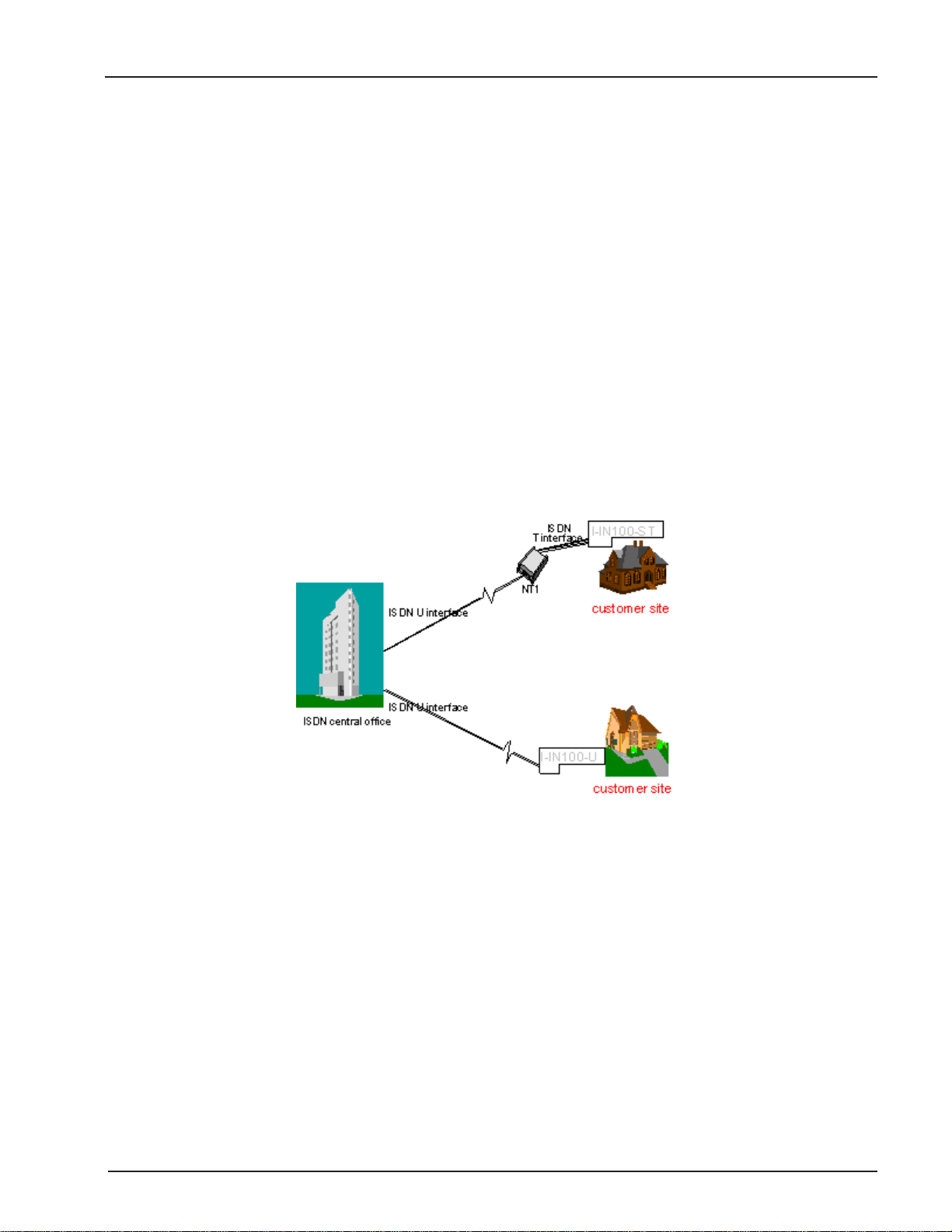
The MT128ISA and MT128PCI are internal PC cards for IBM personal computers; and fit into a full-or halfsized expansion slot. There are two ISDN interface options, ST and U. If you purchased the ST interface
adapter (MT128PCI-SD/SV), you need an ISDN NT1device connection to the ISDN switch. If you purchased
the U interface adapter (MT128ISA-UV), it can directly connect to the ISDN switch (figure 1-1).
Figure 1-1. ST and U Interface Options
Your internal ISDN PC card is compatible with prevalent ISDN switch protocols. It communicates using ISDN
BRI (2B+D) service, which provides up to 128K bps data communications.
This manual documents the following models:
MT128PCI-SD for ST interface no POTS port
MT128PCI-SV for ST interface with one POTS port
MT128ISA-UV for U interface with one POTS port
All of the current analog devices, including telephone set, G3 fax, answering machine, modem, and PBX trunk
line, can be connected to the POTS port via an RJ-11 jack in V models.
This User Guide will help you install, configure, and operate your terminal adapter.
MT128ISA/PCI
5
Page 6

Features
Your internal ISDN PC card features include:
D Channel protocols including AT&T 5ESS, Nortel DMS-100, US NI-1 & NI2, ETSI and
Japan INS-64.
Full B Channel protocol set including V.110, V.120, HDLC, X.75 (Transparent T.70NL,
EuroFT), MLP, async to sync PPP conversion and MLP+BOD and voice (V models).
Bandwidth on demand (BOD) plus MLP Internet connection, RAS and related data
communications capabilities.
ISDN BRI (2B+D) and analog ports.
Modem applications support with ISDN throughput and digital transmission quality, e.g.,
PC Anywhere.
Video conferencing support without extra video CODEC hardware, e.g. Vdonets
Vdophone.
Software implementation of G3 fax and modem capability with no extra hardware re-
quired.
Supports Application Interfaces including WinISDN, CAPI 2.0, Windows Comm (AT
command/S-Register/Result Codes) and NDISWAN Miniport.
Automatic detection of incoming calls as voice or data (V models).
Supports Windows 98, Windows NT and Windows 2000 Multilink PPP connection.
Supports Microsoft ISDN Accelerator Pack or Microsoft Dial-up Networking.
PnP compatibility.
Ability to use the same communications software as analog modems.
AT command ATS30=n, which automatically disconnects the active connection if there is
no data traffic for n x 10 seconds.
Provides On-line test and Diagnostics tools.
Chapter 1 - Introduction
What Is in Your MultiModemISDN Package?
Before installing your terminal adapter, check the package contents to ensure it includes:
One internal ISDN PC adapter
MT128-series System CD containing modem driver and User guide
RJ-45 cable (6 ft.) for ISDN connection
RJ-11 cable for POTS connection (V models only)
Quick Start Guide
RJ11-BTS adapter (UK only)
Note: If any of these items are missing, please contact Multi-Tech Systems or your dealer/distributor.
MT128ISA/PCI
6
Page 7

Chapter 1 - Introduction
Manual Organization
This manual is divided into five chapters and three appendices:
Chapter 1 Introduction and Description
Chapter 1 summarizes the products features, lists its technical specifications, and provides an overview of the
manuals organization.
Chapter 2 Installation
Chapter 2 describes how to make all the physical and software driver connections necessary for your terminal
adapter to operate in an ISDN environment.
Chapter 3 AT Commands
Multi-Techs ISDN adapters supports Microsoft Windows Comm. API interface. This interface is similar to a
modem interface and enables existing applications based on AT commands to access ISDN. Chapter 3
describes AT commands used to control your MultiModem ISDN terminal adapter.
Chapter 4 Troubleshooting
This chapter provides general and specific problem solving steps for use with the MT128 internal adapter. The
chapter also includes information about this products LOG utilities as well as the Windows 2000
LINETEST utility used for testing the ISDN line status.
Chapter 5 Warranty and Service
Chapter 5 provides the terms of your 2 year warranty and describes how to get service.
Appendices
Appendix A - FCC Regulations
Appendix B - Application Program Interfaces (APIs)
Appendix C - Applications
MT128ISA/PCI
7
Page 8

Chapter 1 - Introduction
Technical Specifications
Model Number(s): MT128ISA-UV, MT128PCI-SD and MT128PCI-SV
Network Interface: RJ-45 S/T Interface or RJ-45 U Interface
RJ-11 POTS Interface (V models)
Switch Compatibility: AT&T 5ESS, Nortel DMS-100, US NI-1 & NI2, ETSI, INS-64
B-Channel Protocols: Voice, Data (56K, 64K, 112K or 128K HDLC), V.120, X.75,
Async. PPP to Sync. PPP conversion
Voice Coding: PCM: A-Law (Europe); u-Law (US)
Application Interfaces: WinISDN, CAPI 2.0, Windows Comm. API with AT command sets (COM port
emulation), NDISWAN Miniport for Windows 98, Windows NT and Windows 2000.
Supported Applications: Applications with WinISDN interface such as NetManages Internet Chameleon.
Applications with CAPI interface such as RVS-COM.
Applications with Windows Comm. API such as Microsoft HyperTerminal,
PC Anywhere, Co-Session.
Applications with NDISWAN interface such as Microsoft Dial-Up Networking
and RAS.
Hardware: 16-bit adapter available in ISA bus, 32-bit adapter available in PCI bus,
PnP for Windows 98, Windows NT and Windows 2000 systems.
Warranty: 2 years
MT128ISA/PCI
8
Page 9

Chapter 2 - Installation
Chapter 2 - Installation
Introduction
This chapter describes how to make all the physical and software driver connections necessary for your
terminal adapter to operate in an ISDN environment. Please check the package contents list in Chapter 1
before beginning your installation.
ISDN BRI Line
Before running the ISDN adapter, you need to get an ISDN BRI (Basic Rate Interface) line from your local
telephone company. Your ISDN service provider will provide information to you about the ISDN central switch
type, pertinent subscriber information and SPID (Service Profile ID) number(s).
SPID (Service Profile ID)
The Service Profile ID (SPID) is applicable in the U.S. only. SPIDs are a series of numbers that inform the
central office switch which services and features to provide to an ISDN device. The generic SPID format
comprises 14 digits. The first 10 digits are the main telephone number on the terminal. The last 4 digits are
dependent on the number of terminals on the interface and the services they support.
NT1 Connection
An ISDN Basic Rate (BRI) U-Loop consists of 2 conductors from the CO (telephone company central office) to
the customer premises. The equipment on both sides of the U-loop has been designed to deal with the long
length of the U-loop and the noisy environment it operates in. At the customer premises the U-loop is terminated by an NT1 (network termination 1) device. An NT1 is a device which provides an interface between the
two-wire twisted-pairs used by telephone companies in their ISDN BRI network and an end-users four wire
terminal equipment. The NT1 drives an S/T-bus which is usually made up of 4 wires, but in some cases may
be 6 or 8 wires.
The name of the S/T bus comes from the letters used in the ISDN specifications to refer to two reference
points, S and T. Point T refers to the connection between the NT1 device and customer supplied equipment.
Terminals can connect directly to NT1 at point T, or there may be a PBX (private branch exchange, i.e. a
customer-owned telephone exchange). When a PBX is present, point S refers to the connection between the
PBX and the terminal. Note that in ISDN terminology, terminal can mean any sort of end-user ISDN devices,
such as data terminals, telephones, FAX machines, etc. The diagram which follows reflects interface points in
a typical ISDN network.
If your ISDN product operates with a S/T outlet interface, you need an NT1 device to connect to the ISDN
switch. MT128PCI-SD/SV adapters need an NT1 device to connect to the ISDN switch, but the MT128ISA-UV
adapter does not require NT1 device. In the UK, and in many European countries, an NT1 device is supplied
by your telephone company.
MT128ISA/PCI
9
Page 10
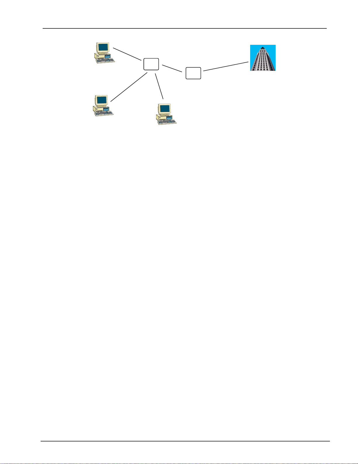
Point “S”
4-8 Wires
Chapter 2 - Installation
Terminal
Point “S”
Terminal
NT2
(PBX)
Point “T”
4-8 Wires
Point “S”
Terminal
NT1
Point “U”
2 Wires
Figure 2-1 ISDN Interface Points
S/T Interface
The S/T interface uses an 8-conductor modular cable terminated with an 8-pin RJ-45 plug. An 8-pin
RJ-45 jack located on the terminal is used to connect the terminal to the DSL (Digital Subscriber
Loops) using this modular cable.
Table 2-1 shows the Pin Number, Terminal Pin Signal Name and SILC Pin Signal name for the S/T
interface.
Pin Number Terminal Pin Signal Name SILC Pin Signal Name
1 Power Source 3 Not applicable
2 Power Source 3 Not applicable
3 Tx+ Rx+
4 Rx+ Tx+
5 Rx- Tx6 Tx- Rx7 Power Sink 2 (-) Not applicable
8 Power Sink 2(+) Not applicable
Table 2-1. S/T Interface Connector Specification
U Interface
The U interface uses a 2-conductor twisted pair cable terminated with an RJ-45 jack. An RJ-45 jack
located on the terminal is used to connect the terminal to the Digital Subscriber Loops using this
twisted pair cable.
In Table 2-2 the Pin Number, Terminal Pin Signal Name and UILC Pin Signal Names for the U interface are listed.
Pin Number Terminal Pin Signal Name UILC Pin Signal Name
MT128ISA/PCI
1 Not Used Not applicable
2 Not Used Not applicable
3 Not Used Not applicable
4 Tip or Ring Tip or Ring
5 Tip or Ring Tip or Ring
6 Not Used Not applicable
7 Not Used Not applicable
8 Not Used Not applicable
Table 2-2. U Interface Connector Specification
10
Page 11

Chapter 2 - Installation
Internet Access
If you want to use an ISDN adapter to connect to the Internet, you must get an Internet access account from
an ISP (Internet Service Provider) in your country. You must also confirm with your ISP that they support either
single channel ISDN (64K) or multilinked channel (128K) access.
Safety Warnings
1. Never install telephone wiring during a lighting storm.
2. Never install telephone jacks in wet locations unless the jack is specifically designed for
wet locations.
3. This product is to be used with UL and cUL listed computers.
4. Never touch uninsulated telephone wires or terminals unless the telephone line has been
disconnected at the network interface.
5. Use caution when installing or modifying telephone lines.
6. Avoid using a telephone (other than a cordless type) during an electrical storm. There
may be a remote risk of electrical shock from lightning.
7. Do not use the telephone to report a gas leak in the vicinity of the leak.
8. To reduce the risk of fire, use only No. 26 AWG or larger Telecommunication line cord.
9. Ports that connect to other apparatus are defined as SELV. To ensure conformity wtih EN
41003, ensure that these ports connect only to the same type of port on the other appara-
tus.
Environment Setup
All ISDN adapter models are Plug and Play (PnP) compatible. Even if the BIOS or computer main board does
not provide PnP feature support, the device driver still can automatically configure the ISDN card with the
proper I/O addresses and IRQ number.
MT128ISA/PCI
11
Page 12
Hardware Installation
Note: Disregard step 1 for models MT128ISA-UV only, and proceed to step 2.
1. The ISDN S/T interface can support up to 8 ISDN terminals and NT1 device connecting to
the ISDN network. Only one ISDN S/T device should have the terminator enabled.
Normally, the ISDN terminal farthest from NT1 should have the terminator enabled.
Models MT128PCI-SD/SV and MT128ISA-UV provide two jumpers (JP1 and JP2) for the
terminator setup. The default setting for the adapter(s) is terminator enabled. If there are
other ISDN devices connected to the NT1 with ISDN adapter(s), and you do not require
your adapter as a terminator, remove the JP1 and JP2 shorting plugs (open circuit).
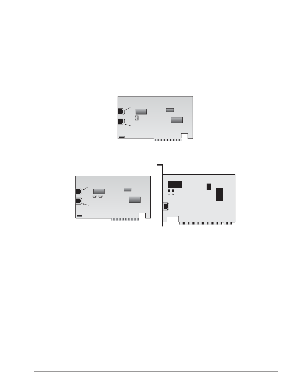
Figure 2-2. Internal ISDN ISA Adapter Illustration
RJ11/Analog Connection
JP1
JP2
RJ45/ISDN
MT128ISA-Data/Voice
Chapter 2 - Installation
RJ11/Analog Connection
JP2
JP1
RJ45/ISDN
MT128PCI-Data/Voice
J2
J1
Figure 2-3. Internal ISDN PCI Adapter Illustrations
2a. Turn off your computer power and remove the PC cover.
2b. If you are using an ISA card, select an empty ISA slot for your adapter. If you are using a
PCI adapter, select an empty PCI slot for your card. Remove the expansion slot cover
and save the retaining screw.
2c. Before handling your adapter, discharge static in your body by touching a piece of
grounded metal such as the computer chassis.
2d. Carefully remove the ISDN adapter from the antistatic bag, handling it only by the mount-
ing bracket and edges. Do not touch the gold-plated connectors along the bottom edge.
2e. Place the adapter directly over the appropriate open slot. (If you are using an ISA adapter
insert the card into the open ISA slot selected in Step 2b. If you are using a PCI card,
insert the adapter into an open PCI slot.) Gently push the connector into place until the
adapter is firmly seated and the retaining bracket is flush with the computer chassis.
Fasten the bracket to the computer chassis with the screw removed in Step 2b.
2f. Replace the PC cover.
MT128ISA/PCI
12
Page 13
Chapter 2 - Installation
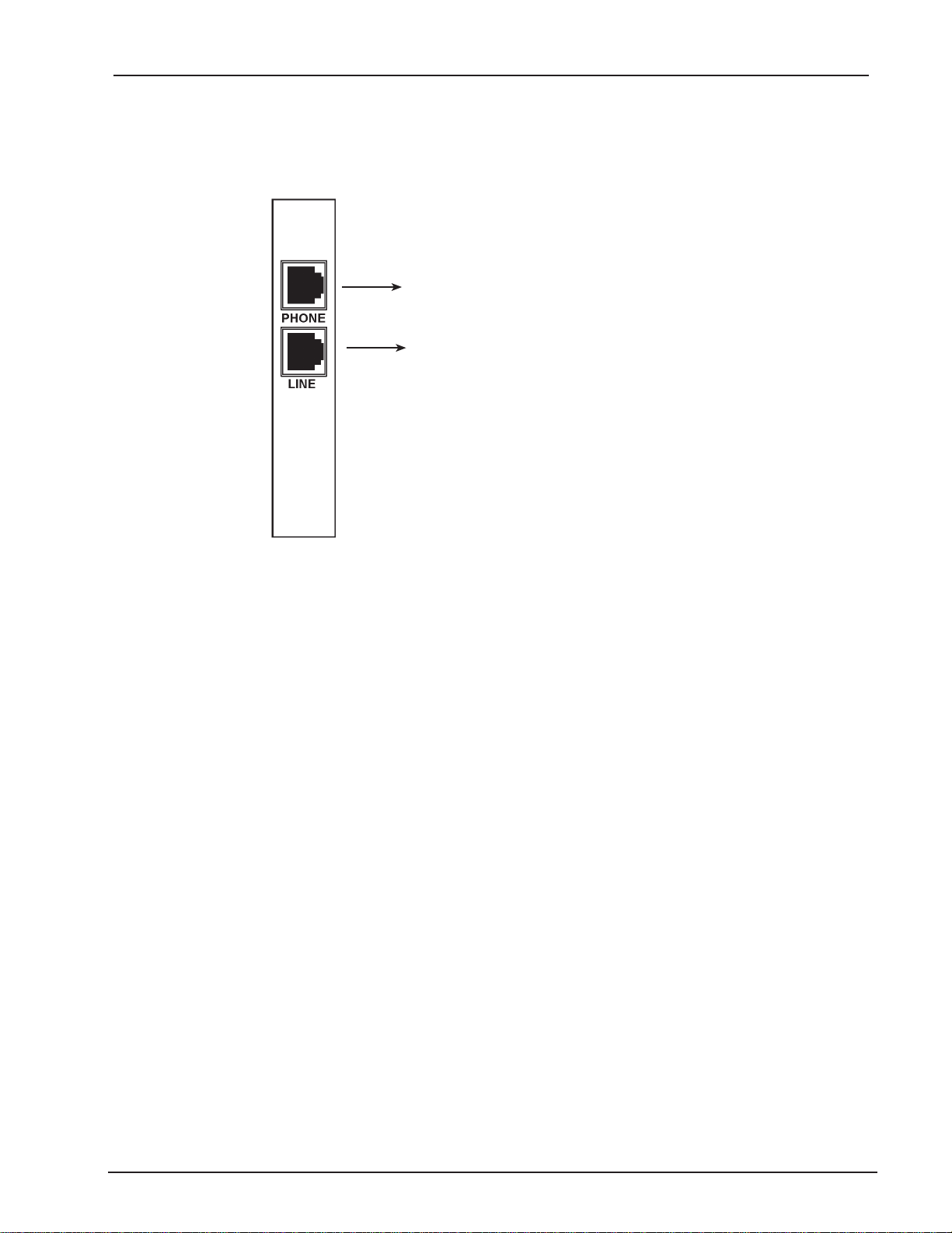
3. If you are using a voice model adapter (models MT128ISA-UV or MT128PCI-SV only) you
may connect your current analog device to the RJ-11 Phone port. You can connect
analog telephones, G3 fax, modem, or an answering machine with the RJ-11 connector
cable.
RJ11 Analog Connection
(Telephone, G3 Fax, Answering Machine,
Modem or PBS Trunk)
RJ45 BRI Connection
Figure2-4. Modular Analog and BRI Connections
4a. Make the ISDN connection by connecting the MT128PCI-SD/SV adapter and the NT1
with the RJ-45 cable connector, and insert the ISDN BRI line into the correct NT1 socket.
OR
4b. Insert the ISDN BRI line with the RJ-45 connector cable directly into the RJ-45 jack (Line
port) on the MT128ISA-UV adapter.
Your ISDN PC environment is ready for software installation. The MT128PCI-SD/SV and adapters attach to
the ISDN T interface from the NT1. The MT128ISA-UV adapter attaches to the ISDN U interface directly with
ISDN switch.
MT128ISA/PCI
13
Page 14

Chapter 2 - Installation
Software Installation
Before You Begin
After installing the terminal adapter in your computer youll need to install and configure the adapter drivers,
then set up dial-up connections.
If your ISDN application uses the CAPI interface, install a CAPI compliant application such as RVS-COM Lite.
Before you can configure your software you need to determine how you plan to use your ISDN adapter. The
MultiModem ISDN terminal adapter uses three basic APIs which are further described in Appendix B of this
manual. In general:
NDISWAN connections are used for connections to the Internet, a remote Local Area Network or for
RAS installations. Upon installing NDISWAN the following adapters and protocols are installed on
your system:
IINWAN95-ISDN Adapter
NDISWAN-IINWAN95-ISDN Adapter
VCOMM or the Virtual Modem is used for ISDN applications that do not use networking protocols,
(e.g., HyperTerminal or PCAnywhere).
ISDN (Internet MLPPP over X.75, 128K) Adapter
ISDN (Internet MLPPP+BOD over X.75, 128K) Adapter
ISDN (Internet MLPPP, 128K) Adapter
ISDN (Internet PPP over X.75, 64K) Adapter
ISDN (Internet PPP, 64K) Adapter
ISDN Universal-1 (64K) Adapter
ISDN Universal-2 (64K) Adapter
CAPI allows for such functions as faxing. Youll need to install a CAPI compliant application such as
RVS-COM Lite to use this API. Installing RVS-COM Lite will make the following modems available:
RVS ISDN
RVS ISDN Btx
RVS ISDN Fax
RVS ISDN HDLC transparent
RVS ISDN Internet PPP
RVS ISDN Minitel
RVS ISDN Modem Analog
RVS ISDN V.110
RVS ISDN V.120
RVS ISDN X.75 T.70NL
RVS ISDN X.75 transparent
Determining Modem Type
Refer to the following information for assistance in selecting the appropriate modem for your ISDN application.
The Internet MLPPP protocol is for connecting to Internet Servers and other point-to-point
(PPP) protocol servers using the Multi-Link Point-to-Point protocol. MLPPP is the only
protocol which can link two ISDN B-channels to establish a 128 kilobits per second
bandwidth data path.
Note: Before attempting to make a 128K MLPPP connection, verify that your ISP supports this
feature.
X.75 protocol is used mostly for BBS access and file transfer, but may be used for Internet
access in some locales.
The Universal-1 and -2 are multi-purpose modems. In Universal modem mode, the ISDN
driver selects HDLC protocol as the default. You can change to the appropriate protocol
through the ATBn commands (see Chapter 3). The AT command can be issued through
MT128ISA/PCI
14
Page 15

Chapter 2 - Installation
Start>Settings>Control Panel>Modems>ISDN modem>Properties>Connection,
Advanced>Extra settings.
The Internet PPP protocol is for connecting to Internet and other communications servers
at 64 kilobits per second. Only one B-channel is used, leaving the other free (if supplied
by your ISDN service provider) for a different data transfer operation or a voice or fax call.
BOD means Bandwith on Demand. BOD first establishes a 1B (64K) data channel and
waits until data traffic is over the value specified in ATS53 (see Chapter 3 for more
information about AT commands). When data traffic goes over this default value (or the
value set in the user-specified AT command), BOD establishes a second B channel and
bundles it to a 128K communication link for better performance. BOD allows greater
flexibility in handling voice and data calls simultaneously.
Bandwidth on demand is very useful where ISDN access is charged for by the minute, since the second Bchannel is only used when the volume on the first B-channel has exceeded a threshold value for a certain
period of time.
Before BOD activates all three of the following conditions must be met:
Average data traffic is lower than the value (ATS53) in a specific period (ATS54)
User wants to make an outgoing voice call (picks up the handset)
There is an incoming voice call (ring signal on an analog telephone device)
MT128ISA/PCI
15
Page 16

Chapter 2 - Installation
Configuring for Your ISDN Switch
Regardless of the operating system or application you are using, the installation process will request information from you about the ISDN switch and your remote connection. Use the following information as a reference while configuring your software.
ISDN Switch Type
If you are not sure which switch type you are using, check with your ISDN provider.
Codec
Telephone companies use Codecs to convert signals transmitted over their networks. Telephone
service providers that adhere to U.S. telecommunications standards use u-law. Many European and
Asian telephone companies adhere to A-Law. Check with your ISDN provider if you are unsure which
value to select.
Standby Time
Standby time is a timer which buffers any keypads input from an analog device before sending a
message out. In general, this value will not need to be changed from the default value.
SPID
Certain U.S. ISDN switch types require SPID (Service Profile ID) information be configured in your
software. If required, your telephone company will provide the necessary SPID values. SPID1 refers
to the first ISDN line. SPID2 refers to the second ISDN line.
MSN (POTS)
MSN (Multiple Subscriber Number) is a supplementary service generally used by European ISDN
switches. MSN service provides the possibility of assigning multiple ISDN numbers to a single interface. The POTS field is used to enter the phone number associated with a voice line. In a two
channel ISDN configuration, if the MSN (POTS) field is left blank, either number can ring. If a phone
number is entered, the number dialed on the incoming call must match the MSN (POTS) value for the
analog device connected to the POTS (voice) (a/b) port to be enabled.
SAD
SAD (Sub addressing) is used by certain European ISDN providers. If subaddresses are available in
your area enter the phone number in the format, 7706043*1, where 7706043 is the called (remote)
phone number and 1 is the subaddress. The phone number and subaddress are separated by *.
Protocol
In some configurations, you will need to select HDLC, X.75 Transparent, V.120 or Auto-Detection as
your incoming protocol. The incoming protocol selection is based upon the protocol of your ISDN
adapter. The outgoing protocol selection is based upon the protocol of the remote ISDN device to
which you are connecting.
MT128ISA/PCI
16
Page 17

Chapter 2 - Installation
Install the Modem Driver on Win 98/Me/2000/XP
For Windows 98/Me/2000/XP operating systems, install the modem driver using the Windows Plug and Play
feature. Follow the procedure below to install the modem driver.
1. Verify the modem is properly connected, then turn on the computer. Windows will detect
the new modem and open the Install New Hardware wizard.
2. Insert the MT128-series system CD.
3. Point to the Drivers folder on the CD (Drivers/Win98_Me or Drivers/Win2000-XP. Click OK
at the Install New Hardware prompt.
3. Windows will install and configure the modem.
4. Click Finish at the prompt to exit.
Windows NT Installation and Configuration
Note: To install, configure and remove devices under NT, your logon permissions must include the
ability to load and remove device drivers.
Your internal ISDN PC adapter under Windows NT can be used with NDISWAN or the standard CAPI interface. Once youve inserted the ISDN card into the computer and switched on the power for your computer, it
should boot into Windows NT. Follow the instructions below to install the ISDN driver:
1. Click Start>Settings>Control Panel>Network>Adapter> Add
2. Click Have Disk and specify the correct drive for the NT ISDN Installation disk/CD.
3. On the Select OEM Option Screen, select the ISDN MT128ISA Adapter. Click OK.
4. The ISDN Driver Bus Location dialog box appears. Select the proper bus type for your
installed adapter. If you are using an ISA adapter, select ISA. If you are using a PCI
adapter, select PCI. Set the Bus Number to 0. Click OK.
5. Windows NT copies the ISDN driver into your system and displays the ISDN PC Adapter
Configuration screen as shown in figure 2-5.
Note: If the ISDN PC Adapter Configuration screen does not appear automatically or if you need to
edit your ISDN Switch configuration, return to this screen by selecting
Start>Settings>Control Panel>Network. Right click and select Properties.
MT128ISA/PCI
Figure 2-5. ISDN PC Adapter Configuration
17
Page 18

Chapter 2 - Installation
6. Use the list box to select the Switch Type. If you are not sure which Switch Type to select,
contact your ISDN provider. If your telephone service provider uses MSN (Multiple
Subscriber Numbers) or SAD (Sub-Addressing), enter the information given to you by
your ISDN provider in the appropriate fields. If your ISDN service requiresSPIDs (Service
Provider IDs), enter these values in the SPID1 and SPID2 fields. Refer to Chapter 2
Before You Begin for more information.
Note: If you plan to use PTP Mode (Point to Point Mode) or X.25 select those options here.
7. Click on the NDISWAN Setting tab and enter any necessary phone number information.
Note: After installation and any time you make changes to values within the ISDN configuration
dialog box, you will need to restart Windows NT for the settings to take effect.
8. When complete, Click OK to continue. The RAS Setup Message appears as shown in
figure 2-6. Click OK to continue the installation.
Figure 2-6. Remote Access Service Setup Message
9. Click OK to install and setup RAS.
10. The screen shown in figure 2-7 appears.
Figure 2-7. Adding a RAS device
11. If you do not see ISDN1-IINWANNT listed in the port fields, click Add.
12. From the list box, select ISDN1-IINWANNT and click OK. The first NDISWAN device is
added to the Remote Access Setup Port list.
MT128ISA/PCI
18
Page 19

Chapter 2 - Installation
13. Add your second NDISWAN ISDN device by clicking Add and selecting ISDN-2-
IINWANNT from the list box. Click OK to add this device to the RAS Setup as shown in
figure 2-8.
Figure 2-8. Remote Access Services (RAS) Setup
14. Select the ISDN1 and click Configure to setup Port Usage for this ISDN1port. Depending
upon your use of this channel, select Dial out only, Receive calls only, or Dial out and
Receive calls. Click OK.
MT128ISA/PCI
Figure 2-9. Configure Port Usage Installation
15. If you choose Dial out only, click OK, and then click the Network tab. Select the protocol
you will use. If you are going to access the Internet, choose TCP/IP.
Figure 2-10. Configure Dial Out Protocol
16. If you Select Receive calls, or Dial out and Receive calls, click OK, then click the Network
19
Page 20

Chapter 2 - Installation
tab. The screen displayed in fiigure 2-11 appears. Contact your ISP or network adminis-
trator if you require assistance in configuring your TCP/IP settings. Also check that you
have enabled, allow any authentication including clear text, in the Security settings. Click
OK.
Figure 2-11. Define Network Configuration
17. Select ISDN2 and click Configure to set up the appropriate values for the second line.
18. You have completed your ISDN driver installation and have added two NDISWAN adapt-
ers. Click Continue>Close. NT will bind the appropriate drivers to your adapter and you
will be prompted to restart your computer.
Windows NT Single Channel Access (NDISWAN)
Once your adapter is installed, you are ready to set up an ISDN Dial-Up Networking connection for single
channel access.
1. Select Start>Programs>Accessories>Dial-Up Networking. If there are no previous
entries in your phonebook, a dialog box appears stating The Phonebook is empty. Press
OK to add an Entry. The New Phone book entry wizard appears. Enter a name for your
new Phone Book entry. In the Dial Using field, select the IINWANNT NDISWAN adapter
you will use for this connection.
2. Next, enter the primary phone number for your ISP or remote server. If you need to
specify a Country, Region or Area code, click on the Telephony dialing properties box and
fill in your dialing information. If your ISP or remote server has more than one phone
number that can be dialed, click on Alternate Phone Numbers and add the phone
numbers to the screen.
3. On the Server tab, select the correct remote Server Type. Click on TCP/IP to set up
addresses for your remote server. Click OK to continue.
4. When complete, click OK>Close.
5. To use this new connection, open the Dial-Up Networking folder and select the NDISWAN
single channel access entry from the phonebook entry drop down list box. Click Dial.
6. Enter the user name and password for your ISP or remote server account and click OK.
Your adapter will connect in seconds.
MT128ISA/PCI
20
Page 21

Chapter 2 - Installation
Windows NT Multilinked Channel Access (NDISWAN)
Before beginning installation of a 128K MLP connection, verify your ISDN provider offers 128K MLP service
and that it is enabled on the remote server.
In the following example the single channel access connection created in the previous section will be modified
to support a 128K MLP connection.
1. Open the Network Dial-Up Connection folder and select the NDISWAN Single Channel
Access connection created in the previous section.
2. Click the More button and select Edit entry and modem properties.
3. Under the Basic tab, use the Dial Using field list box to select Multiple Lines.
4. Click Configure and place a check mark in the boxes corresponding to
IINWANNT(ISDN1) and IINWANNT(ISDN2).
Figure 2-12. Multiple Line Configuration
5. Highlight IINWANNT(ISDN1). Click Phone numbers and enter the phone number for the
first ISDN line if it is not yet installed. Click Add, then OK.
6. Next, highlight IINWANNT(ISDN2). Click Phone numbers and enter the phone number
for the second ISDN line. Click Add, then OK. Click OK again to close the screen.
7. You are ready to make a connection with your ISP or remote server using multilinked
channels. To use this new MLP connection, open the Dial-Up Networking folder and select
the NDISWAN multiple linked channel entry from the phonebook entry list box. Click Dial.
8. Enter the user name and password for your ISP or remote server account and click OK.
Your adapter will connect in seconds.
9. After dialing, the Dial-Up Monitor icon appears in the lower right hand corner of your
screen. Double click on this icon to view your connection status including connection
speed, server type, etc.
Note: If you have problems with the connection (such as the line being dropped or inability to access
the Internet or your remote network), review the network settings with your ISP or network
administrator. You also may want to test accessing the connection without using Multilinking.
MT128ISA/PCI
21
Page 22

Chapter 2 - Installation
Windows NT and the CAPI Interface
Before using the standard CAPI interface, install a CAPI compliant application such as RVS-COM Lite.
Under NT, The CAPI modems available through RVS-COM must be added as modems and also made
available through RAS (Remote Access Services). To add a new modem:
1. Select Start>Settings>Control Panel>Modems>>Add
2. Select Dont detect my modem, I will select it from a list.
3. On the Install New Modem screen, select RVS Datentechnik from the Manufacturers list
on the left side of the window. The RVS modems will display in the models column on the
right side of the window. Select the RVS-COM modem you would like to use for your
ISDN connection (in this example RVS Fax has been selected). Click Next to continue.
Figure 2-13. Selecting an RVS-COM modem
4. On the screen which follows, select the port youd like to associate with this modem. Click
Next>Finish to finish adding this first modem.
You may press OK when complete. If you will be using linked channels, Add the second
modem at this time by repeating the steps above. Associate the second modem with a
unique COM port.
5. The screen shown in figure 2-14 appears asking if you would like to configure Dial-Up
Networking. Respond by clicking Yes.
Figure 2-14. Dial-Up Networking dialog box
MT128ISA/PCI
22
Page 23

Chapter 2 - Installation
6. The Remote Access Setup Screen displays (figure 2-15).
Figure 2-15. Selecting the CAPI (RVS-COM) device in RAS
7. Add the RVS-COM device to Remote Access Services by clicking Add. From the device
list, highlight the desired modem and click OK.
8. With the newly added device highlighted, click Configure. You will be presented with the
Configure COM Port Usage screen. Select an available ISDN COM port for this device
and select either Dial-Out only, Receive Calls Only or Dial-Out and Receive calls.
Click OK when complete.
If you will be setting up 128K MLP access, you may click Add on the Remote Access
Setup screen and add the second RVS-ISDN device. When the second device has been
added, highlight this new device and click Configure to define the COM port usage for
this channel.
After adding the devices to RAS for this connection, click Continue. Restart the computer
as prompted.
Note: If you add a modem at a later date, it must be added to Windows NT RAS before it can be
used.
To add the modem to RAS:
1. From your NT desktop, right click on Network Properties and select Properties.
2. Click the Services tab.
3. When the RAS Services screen appears, select Add.
4. Select the modem youd like to use with your application. Next, press Continue.
5. Associate the modem to a unique COM port and save the connection.
6. When the Network Properties screen closes you will be prompted to restart the computer.
MT128ISA/PCI
23
Page 24

Chapter 3 - AT Commands
Windows NT Single Channel Access (CAPI)
The RVS-COM installation makes several RVS-COM (CAPI compliant) modems available. Once they are
added as modems and set up under RAS, you are ready to set up your Dial-Up connection.
1. Set up the Dial-Up Networking connection by selecting Programs>Accessories>Dial-Up
Networking.
2. Click New. Provide a descriptive name for this connection and enter the phone number
for your remote server or ISP.
3. Next, select the CAPI (RVS-COM) modem and COM port for this connection in the Dial-
Using field.
4. When complete, click the Server tab and verify the Dial-Up server type. Click the TCP/IP
settings tab if you need to specify IP addresses for your remote server or DNS. Contact
your ISP or network administrator for information on configuring this screen.
5. Click OK to return to the Network Dial Up folder.
To use this connection, highlight the connection and click Dial. Your ISDN adapter will
connect within seconds.
Windows NT Multilinked Channel Access (CAPI)
Before a second channel can be linked using CAPI, a second port must be defined within RVS-COM.
1. To make the second port available, open the RVS-COM Comm Center.
2. Click the Services tab. In the Virtual COM Ports section of the window, place a check
mark in front of both ports. Associate each port with a unique COM port number (the two
devices must use different COM ports.) Click Apply, then OK.
If the second CAPI device has not been installed add a second RVS-COM modem and
make it available through RAS as described previously in this section.
You are now ready to create your Dial-Up Networking connection for multilinking. In this
example, the Single Channel Access connection will be modified to allow for multilinking.
1. Click on Programs>Accessories>Dial-Up Networking.
2. Select the Single Channel CAPI connection and click More. Select Edit entry and
Modem Properties.
3. In the Dial Using list box, select Multiple Lines.
4. Next, press Configure. Place a check mark in the box associated with the two RVS-
ISDN lines you will be linking.
5. Highlight the first line and select Phone Numbers. If not previously entered, enter the
phone number for this line. Click Add and OK.
6. Highlight the second line and select Phone Numbers. If not previously entered, enter the
phone number for this line. Click Add and OK.
To use this 128K MLP Dial-Up connection, click Programs>Accessories>Dial-Up
Networking. Double click on this newly created CAPI multilink connection. Both phone
lines on your MultiModem ISDN adapter will connect in seconds.
Windows NT Removal of the ISDN Drivers
To remove the ISDN Driver in Windows NT, Click Start>Settings>ControlPanel>NetworkIcon>Adapters.
Select the Multi-Tech ISDN Driver. Click Remove.
You will be prompted to reboot your system when you exit the network properties dialog box. You must reboot
for the changes to take effect.
MT128ISA/PCI
24
Page 25

Chapter 3 - AT Commands
Chapter 3 - AT Commands (Win 98 Only)
Introduction
AT commands are the means by which you and your communications software are able to communicate with
and configure your ISDN adapter. These commands enable you to establish, read and modify parameters
associated with your ISDN connections, line protocols and call handling. The following provides a list of the AT
commands recognized by Multi-Techs MultiModem ISDN terminal adapters.
Where indicated below, the AT prefix must be issued with the command. The AT command tells the modem
ATtention!, commands to follow. If you issue AT as a command by itself, the adapter should respond OK,
indicating that your cables are connected correctly and your baud rate is set properly.
AT commands are entered in HyperTerminal mode or can be issued as an extra setting for your connection.
Use Start>Settings>Control Panel>Modems>ISDN Modem>Properties>Connection>Advanced>Extra
settings.
Commands and Descriptions
ATA Answer an incoming call
ATBn Select protocol of transmission in B channel
ATB0 64K HDLC (default with universal modems under Win95)
ATB20 V.120 Async.
ATB21 V.120 Sync.
ATB3 X.75 Transparent, the same as ATB30 (default with ISDN X.75 Transparent modem under Win95)
ATB30 X.75 Transparent
ATB31 X.75 T.70 NL
ATB32 X.75 ISO 8208
ATB4 Async PPP to Sync PPP converter (default setting with Win95 Async to Sync PPP modem)
ATB41 Async to Sync PPP conversion in ML PPP mode, compatible with Microsoft ISDN Accelerator pack
ATB42 Async to sync PPP conversion to MLPPP
ATB43 Async to sync PPP conversion in MLPPP+BOD (bandwidth on demand)
ATB6 Async to sync PPP conversion over X.75 transmission
ATB61 Async to sync PPP conversion over X.75, but setting up secondary device in Dial-Up Networking
required.
ATB62 Async to sync PPP conversion in MLPPP over X.75
ATB63 Async to sync PPP conversion in MLPPP+BOD over X.75
ATDs Dial a telephone number
ATDL Dial the last number
ATD7693007 Dial telephone number 7693007
ATEn Echo characters when in command mode
ATE0 Echo off
ATE1 Echo on ( default )
ATHn On-Off Hook
ATH On-Hook, Disconnect (same as ATH0)
ATH1 Off-Hook
ATI Display version number, selected protocol, packet size, connected speed, MSN, and outgoing call
number.
ATO On-Line command, switch to on-line from command mode
ATQn Return the result code
ATQ0 Return the result code (default)
ATQ1 Does not return the result code
ATSr Set or display the register value
ATS0=1 Set register 0 to 1, (S0=0 default, disable the auto-answer mode)
ATSr? Display register content
MT128ISA/PCI
25
Page 26

Chapter 3 - AT Commands
ATS1? Register 1 is read only, display the ring count
ATS2 Escape code character (S2=43, ASCII +)
ATS3 Carriage return character (S3=13, representing a carriage return)
ATS4 Line feed character (S4=10, representing CTRL J or the linefeed character)
ATS5 Back space character (S5=8, representing CTRL H)
ATS7 Wait for carrier after dial (S7=30 seconds default)
ATS12 Escape code guard time (S12=50 default )
ATS25 Delay to DTR (S25=5 default )
ATS30 Disconnects automatically if no data transmission in n=10 seconds (n=0 to 255; default is S50=0, so it
does not disconnect connection
ATS38 Windows size of HDLC 56K or 64K, 7 default
ATS39 Packet size of HDLC 56K or 64K from 1 to 2048, 2048 default
ATS40 Windows size of V.120, 7 default
ATS41 Packet size of V.120, 256 default
ATS44 Window size of X.75 (Transparent), 2 default
ATS45 Packet size of X.75 (Transparent) from 12048, 1024 default
ATS46 Window size of X.75 T.70 NL, 2 default
ATS47 Packet size of X.75 T.70 NL from 1 to 2048, 130 default
ATS50 Window size of X.75 ISO 8208, 2 default
ATS51 Packet size of X.75 ISO 8208 from 128 to 2048, 1024 default
ATS53 Average data flow from 1000 to 7000 bytes (default is 4, which is 4000 bytes). Activates second
channel if average data flow is over 4000 bytes in 10 seconds.
ATS54 Time period from 5 to 20 minutes (default is 5). Disconnects second channel if average data flow is
below n bytes (set by ATS53) in 5 minutes. Only available in MLPPP BOD mode, ATB43.
ATVn Verbose command
ATV0 Return digit result code
ATV1 Returns word result code ( default )
ATXn Enable extended result code
ATZ Reset
+++ Escape command
AT&Cn Control DCD
AT&C0 Keep always the DCD line ON ( the same as AT&C, default )
AT&C1 DCD line is active if connected
AT&E Select the line speed in the B channel
AT&E0 64K bps (default)
AT&E1 56K bps
AT&F Reset registers to factory setting
AT&R Request to send
AT&S Handle DSR
AT&S0 Keep DSR always ON ( the same as AT&S )
AT&ZIn*m Filter the incoming call and accept it when called party number is the same as n and called party
subaddress is the same as m (option, * is the subaddress symbol)
AT&ZOn*m Make a call with this caller party number (n * m). n is the local telephone number, * is the sub
address symbol, if needed Command Description (option), and m is the sub address (option).
AT#C Caller ID setting
AT#C? Display the current Caller ID mode
AT#C0 Disable Caller ID (default)
AT#C1 Enable Caller ID
MT128ISA/PCI
26
Page 27

Chapter 4 - Troubleshooting
Chapter 4 - Troubleshooting
Introduction
This chapter provides a list of questions and answers for commonly asked questions about your
MultiModemISDN adapter. In the last part of this chapter you will find information about the LINETEST and
LOG utilities used for diagnosing ISDN line problems. If you are not able to resolve the issues after reading
this section, contact our Technical Support department (see Chapter 5 of this User Guide for more information).
Frequently Asked Questions
Q: How can I get the driver version number?
A: In Win98, run HyperTerminal with a virtual modem connected to ISDN Com1 or 2, enter the
ATI to display the version number. You may also run LOG32.EXE to view the version number
(Version 2.21 or later). In Windows 2000, you may find the driver version by placing your
cursor over the LINKSTS icon on the task bar.
Q: How can I update the ISDN driver to a new version?
A: Download the latest ISDN PC adapter driver form Windows 98, NT and 2000 from our web
site at http://www.multitech.com. In Windows 98, run UPGRADE.EXE to update the driver
automatically, then reboot your system. In Windows NT, remove the existing driver, reboot
your system and install the new version. You will need to reconfigure the software for your
ISDN switch type.
Q: Why cant I use HyperTerminal to dial? (Win 98 only)
A: Make sure HyperTerminal is configured with a virtual modem corresponding to the ISDN COM
port. If you do not have two virtual modems with ISDNCom ports added use
Start>Settings>Control Panel>Modems>Add. Select Have Disk and locate the proper file in
the modem subdirectory of the installation diskette.
Make sure the same protocol is used on both sides. Refer to the ATBn command (see Chapter 3) to set up the correct protocol used on the B channel. ATI will display the current settings.
Q: Why cant I make a data connection through HyperTerminal? (Win 98 only)
A: Ensure the client and remote sides of the connection are using the same protocol to make a
data connection. You may use the ATBn command to set the protocol (refer to AT Commands
in Chapter 3 of this manual). Enter ATI to display information such as Software version
number, B channel protocol, connection speed, packet size, current MSN and current outgoing phone number for billing.
Q: How can I monitor the ISDN line and make sure the ISDN card and line are working properly?
A: When the system boots up and invokes the ISDN driver, the driver will initialize the ISDN card
and selftest the IRQ, I/O, and chipsets. If you do not see any error messages, the ISDN card
and driver are working properly. In Windows 2000, you may run LINETEST.EXE to perform a
line test. It will ask you to enter an ISDN telephone and make a call. Enter a local number to
do a loopback test from your site to the ISDN switch. This will ensure the D and B channels
are working properly. Error messages 3301 and 3302 indicate a problem with the ISDN line.
Q: How can I enable Caller ID in HyperTerminal?
A: The driver does not display Caller ID as a default. If you want to enable Caller ID, enter the
command, AT#C1 and AT#C0. To disable Caller ID, enter AT#C? to give the current status of
Caller ID mode. This function is provided in Version 2.13 and later.
MT128ISA/PCI
27
Page 28

Chapter 4 - Troubleshooting
Q: Why does the Internet connection not work when I upgrade to V2.13 or later?
A: When you upgrade to V2.13, youll need to remove the existing virtual modems and read them
into the system. You can add the virtual modems using the following steps:
1. Start>Settings>Control Panel>Modem>Add>Select Dont detect my modem, I will
select it from a list. Next>Select the modem and click Have Disk. Browse to the location
of the installation diskette and select MDMASU.INF. Click OK> select the ISDN Universal-
1 Modem, Next> associate this modem to ISDN COM port 1.
2. Use the previous step to select the ISDN Universal-2 Modem > associate this second
modem to ISDNCOMport2.
Note: You may also use the Async to Sync PPP modem or the X.75 transparent modem Youll also
find these files in the modem sub-directory of the installation disk.
Q: Why cant I see the correct characters in the HyperTerminal screen when I get a connection
with a remote site?
A: Check to make sure the B channel protocol is the same on both sides of the connection.
Check that the character is 8-bit ASCII or 7-bit ASCII. You can disable the first bit of 8-bit
ASCII to 7-bit ASCII by opening the HyperTerminal settings and changing the terminal type to
VT100. Click the ASCII Setup. In the ASCII receiving section, select Force incoming data to
7-bits ASCII. Click OK.
Q: Why cant I see the ISDN ports in RAS after installing the ISDN driver in WinNT?
A: Follow these steps:
1. Remove the ISDN card via Start>Settings>Control Panel>Network, ISDN card, Re-
move.
2. Reboot the computer.
3. Install the ISDN driver.
4. Redefine the modems to RAS. The two ISDN ports will appear.
Q: How can I set the phone number for outgoing calls and MSN checking for incoming calls using
the NDISWAN interface in WinNT?
A: In WinNT, set MSN1, MSN2, calling party 1, and calling party 2 for the two NDISWAN ports by
using Start>Settings>Control Panel>Network>IINWANNT ISDN
Adapter>Properties>NDISWAN setting. Enter the subaddress information if applicable for
your ISDN switch, otherwise, leave these fields blank.
In most installations, the phone number for outgoing calls is used for billing. MSN is used to
screen and accept preferred incoming calls.
Q: Why does Windows NT detect the ISDN card and request to install its drivers when Windows
A: Windows NT is not a PnP operating system. If Windows NT detects a PnP card during start
Q: Why doesnt Windows NT RAS detect the ISDN Driver?
A: If RAS is not installed on your computer and you install the ISDN driver, you will be presented
MT128ISA/PCI
NT boots up?
up, the operating system has previously installed ISAPNP (this is commonly installed with
sound cards such as SB16 or AWE32). When Windows NT requests ISDN driver installation,
check Do not install a driver and NT will not prompt you again at boot up. Follow the NT
installation instructions in this User Guide to install the NT drivers.
with a prompt asking if you would like to install RAS. Respond Yes and install RAS before
rebooting your computer. If RAS still does not recognize your adapter, remove the ISDN
driver and try reinstalling it. If RAS is still unable to detect the ISDN driver, contact Technical
Support for assistance (see Chapter 5).
28
Page 29

Q: Is it possible to build a point to point (end to end) videophone system based on the ISDN
A: Yes, for versions after V2.24, a point to point videophone system is possible to set up. Youll
Q: I would like to use G3Fax, a voice answering machine and telephony with my ISDN card in a
A: Before using these functions youll need to install a CAPI compliant application such as RVS-
Q: Can I use the MultiModemISDN adapter in a dual processor machine?
A: Yes, In version 2.52, dual processors are supported in Windows NT and Windows 2000.
LINETest
Chapter 4 - Troubleshooting
card?
need the following devices: ISDN Adapter, Sound Card with speaker and microphone, Video
Capture Card, Camera, CPU:P-133, RAM 32M, VDOPhone.
Youll need to add a virtual modem (ISDN Videophone adapter) which runs HDLC at 512 bytes
per-packet (equal to ATB0S39+512). This string can also be added in the Extra Setting field
of the ISDN Universal-1 or Universal-2 adapter if you do not have the new MDMASU.INF file.
You may configure the VDOPhone application by selecting Setup>Modem, select the virtual
modem defined above. Use Setup>Advanced and place a mark in the check box for Use non
H.324 compliant Modem. Complete the other fields according to the requirements of the
specific hardware you are using.
Windows environment. How can I do this?
COM.
Initiate the line test utility in Windows 2000 by clicking on the icon on the taskbar. Select Line Test. Enter your
ISDN telephone number and click Start. The adapter will establish a test call. The status of the ISDN B and D
channels between the terminal adapter and the ISDN switch network will display.
Note: Before using Line Test, make sure your ISDN line is not in use.
LineTest Error Messages (CAPI 2.0)
0x3301 protocol error layer 1
0x3302 protocol error layer 2
0x3303 protocol error layer 3
0x3304 another application got that call
0x3401 unsigned number
0x3402 no route to specified transmit network
0x3403 not route to destination
0x3406 channel unacceptable
0x3411 user busy
0x3412 no user responding
0x3413 no answer from user
0x3415 call reject
0x3416 number changed
0x341a non-selected user clearing
0x341b destination out of order
0x341c invalid number format
0x341d facility rejected
0x341e response to status inquiry
0x341f normal, unspecified
MT128ISA/PCI
29
Page 30

Chapter 4 - Troubleshooting
ISDN LOG
The ISDN Log utility provides six functions including: Start/Stop, Save, Clear, Print, Option and Close. The
following figure (figure 4-1) shows a typical log screen. The upper text box of the Log dialog box displays
ISDN communication information information and the bottom section of the screen displays statistical details of
the D and B-Channel events.
In Windows 98, run LOG32.EXE in the Windows directory.
In Windows NT, run LOG32.EXE located in \WINNT\SYSTEM32.
In Windows 2000, right click on the STATS.EXE icon on the task bar and select Log.
Figure 4-1. The ISDN Log
START/STOP: Begins or ends data logging.
SAVE: Saves the entire log history contents to a file. This file can be e-mailed or printed and faxed to
our technical support center.
CLEAR: Clears the Log contents. You may want to save the data before erasing it.
PRINT: Sends the Log contents to the printer.
OPTION: The Options dialog box allows you to select specific line information for the ISDN D channel,
B channels and CAPI messages to include in the Log.
CLOSE: Terminates the ISDN Log function.
Enable Show statistic to display the bottom section of the log as shown in figure 4-2. Information pertaining to
the ISDN D channel is presented in a manner similar to that of a protocol analyzer. The information for the
ISDN B channels and CAPI is presented in Hex format.
MT128ISA/PCI
Figure 4-2. Options Dialog Box
30
Page 31

ISDN Log Error Messages
You may encounter the following runtime problems:
1. Cannot find CTL3D.DLL. This message indicates that your Windows system does not
support 3D graphics. The ISDN 128K driver will continue to execute normally without the
3D control graphic feature. You may contact your PC or system dealer to upgrade your
Windows system if you would like this feature.
2. Irq Selftest Fail. This message indicates the ISDN 128K VxD driver failed its IRQ self-
test. Check the IRQ values in System Resources by selecting Start>Setting>Control
Panel>System>Device Manager>ISDN card, ISDN PC Adapter>Resource.
The PC system may have a non-PnP device using the same IRQ number as ISDN 128K
adapter. This error is common in systems that have ISA bus sound cards installed using
IRQ5. If your system identifies an IRQ conflict, select another IRQ (probably both hard-
ware and software configurations) for this non-PnP device and reboot the system.
Windows 95 user can change the IRQ used by the ISDN card in the device manager by
using Start>Settings>Control Panel>System>Device Management>Multi-function
adapters>ISDN PC Adapter (Master Device)>Properties>Resources. Disable the Use
automatic settings option. Select Interrupt Request>Change Setting and select an
available IRQ value. If IRQ 5 is not available, IRQ 10 or 12 are often good choices.
Ensure the IRQ you select is not in use by another device.
3. Cannot find ISDN card. This message indicates the ISDN 128K VxD driver does not
find the ISDN 128K adapter when Windows starts. The problem may be associated with
an I/O address or IRQ clash during PnP initialization. Check your system resources as
describe in number 2 above. You may need to reinstall the ISDN 128K driver.
Chapter 4 - Troubleshooting
MT128ISA/PCI
31
Page 32

Chapter 5 - Warranty
Chapter 5 - Warranty and Service
Multi-Tech Systems, Inc. Warranty & Repairs Policies
Multi-Tech Systems, Inc., (hereafter MTS) warrants that its products will be free from defects in material or
workmanship for a period of two, five, or ten years (depending on model) from date of purchase, or if proof of
purchase is not provided, two, five, or ten years (depending on model) from date of shipment.
MTS MAKES NO OTHER WARRANTY, EXPRESS OR IMPLIED, AND ALL IMPLIED WARRANTIES OF
MERCHANTABILITY AND FITNESS FOR A PARTICULAR PURPOSE ARE HEREBY DISCLAIMED.
This warranty does not apply to any products which have been damaged by lightning storms, water, or power
surges or which have been neglected, altered, abused, used for a purpose other than the one for which they
were manufactured, repaired by Customer or any party without MTSs written authorization, or used in any
manner inconsistent with MTSs instructions.
MTSs entire obligation under this warranty shall be limited (at MTSs option) to repair or replacement of any
products which prove to be defective within the warranty period or, at MTSs option, issuance of a refund of the
purchase price. Defective products must be returned by Customer to MTSs factory transportation prepaid.
MTS WILL NOT BE LIABLE FOR CONSEQUENTIAL DAMAGES, AND UNDER NO CIRCUMSTANCES WILL
ITS LIABILITY EXCEED THE PRICE FOR DEFECTIVE PRODUCTS.
Repair Procedures for U.S. and Canadian Customers
In the event that service is required, products may be shipped, freight prepaid, to our Mounds View, Minnesota
factory:
Multi-Tech Systems, Inc.
2205 Woodale Drive
Mounds View, MN 55112
Attn: Repairs, Serial # ____________
A Returned Materials Authorization (RMA) is not required. Return shipping charges (surface) will be paid by
MTS.
Please include, inside the shipping box, a description of the problem, a return shipping address (must have
street address, not P.O. Box), your telephone number, and if the product is out of warranty, a check or purchase order for repair charges.
For out of warranty repair charges, go to: www.multitech.com
Extended two-year overnight replacement service agreements are available for selected products. Please call
MTS at (888) 288-5470, extension 5308 or visit our web site at: www.multitech.com for details on rates and
coverage.
Please direct your questions regarding technical matters, product configuration, verification that the product is
defective, etc., to our Technical Support department at (800) 972-2439 or email: tsupport@multitech.com.
Please direct your questions regarding repair expediting, receiving, shipping, billing, etc., to our Repair Accounting department at (800) 328-9717 or (763) 717-5631, or email: mtsrepair@multitech.com.
Repairs for damages caused by lightning storms, water, power surges, incorrect installation, physical abuse, or
user-caused damages are billed on a time-plus-materials basis.
Repair Procedures for International Customers (Outside U.S.A. and Canada)
Your original point of purchase Reseller may offer the quickest and most economical repair option for your
Multi-Tech product. You may also contact any Multi-Tech sales office for information about the nearest distributor or other repair service for your Multi-Tech product: /www.multitech.com
In the event that factory service is required, products may be shipped, freight prepaid to our Mounds View,
Minnesota factory. Recommended international shipment methods are via Federal Express, UPS or DHL
MT128ISA/PCI
32
Page 33

Chapter 5 - Warranty
courier services, or by airmail parcel post; shipments made by any other method will be refused. A Returned
Materials Authorization (RMA) is required for products shipped from outside the U.S.A. and Canada. Please
contact us for return authorization and shipping instructions on any International shipments to the U.S.A.
Please include, inside the shipping box, a description of the problem, a return shipping address (must have
street address, not P.O. Box), your telephone number, and if the product is out of warranty, a check drawn on a
U.S. bank or your companys purchase order for repair charges. Repaired units shall be shipped freight
collect, unless other arrangements are made in advance.
Please direct your questions regarding technical matters, product configuration, verification that the product is
defective, etc., to our Technical Support department nearest you or email: tsupport@multitech.com. When
calling the U.S., please direct your questions regarding repair expediting, receiving, shipping, billing, etc., to
our Repair Accounting department at : +(763) 717-5631 or email: mtsrepair@multitech.com.
Repairs for damages caused by lightning storms, water, power surges, incorrect installation, physical abuse, or
user-caused damages are billed on a time-plus-materials basis.
Repair Procedures for International Distributors
Procedures for International Distributors of Multi-Tech products are on the distributor web site:
www.multitech.com
Online Warranty Registration
If you have access to the World Wide Web, you can register your Multi-Tech product online at:
www.multitech.com
Service
U.S. and Canadian Customers
In the event that service is required, products may be shipped, freight prepaid, to our Mounds View,
Minnesota, factory:
Multi-Tech Systems, Inc.
2205 Woodale Drive
Mounds View, MN 55112
Attn: Repairs, Serial #______
A Returned Materials Authorization (RMA) is not required. Return shipping charges (surface) will be
paid by MTS. Please include inside the shipping box a description of the problem, a return shipping
address (must have street address, not P.O. Box), a telephone number, and if the product is out of
warranty, a check or purchase order for repair charges.
For out of warranty repair charges, go to www.multitech.com
Extended two-year overnight replacement agreements are available for selected products. Please call
MTS at 888 288-5470, extension 5308, or visit our web site at: www.multitech.com for details on rates
and coverages.
Please direct your questions regarding technical matters, product configuration, verification that the
product is defective, etc., to our Technical Support department at 800 972-2439 or e-mail
tsupport@multitech.com.
Please direct your questions regarding repair expediting, receiving, shipping, billing, etc., to our Repair
Accounting department at 800 328-9717 or +763 785-3500, or e-mail mtsrepair@multitech.com.
MT128ISA/PCI
33
Page 34

Chapter 5 - Warranty
Repairs for damages caused by lightning storms, water, power surges, incorrect installation, physical
abuse, or user-caused damages are billed on a time-plus-materials basis.
International Customers (outside U.S.A. and Canada)
Your original point of purchase reseller may offer the quickest and most economical repair option for
your Multi-Tech product. You may also contact any Multi-Tech sales office for information about the
nearest distributor or other repair service for your Multi-Tech product: www.multitech.com
In the event that factory service is required, products may be shipped, freight prepaid, to our Mounds
View, Minnesota, factory. Recommended international shipment methods are via Federal Express,
UPS or DHL courier services, or by airmail parcel post; shipments made by any other method will be
refused. A Returned Materials Authorization (RMA) is required for products shipped from outside the
U.S.A. and Canada. Please contact us for return authorization and shipping instructions on any
international shipments to the U.S.A. Please include, inside the shipping box, a description of the
problem, a return shipping address (must have street address, not P.O. Box), your telephone number,
and if the product is out of warranty, a check drawn on a U.S. bank or your companys purchase order
for repair charges. Repaired units will be shipped freight collect, unless other arrangements are made
in advance.
Please direct questions regarding technical matters, product configuration, verification that the product
is defective, etc., to our Technical Support department nearest you, as listed at: www.multitech.com or
e-mail: tsupport@multitech.com. When calling the U.S., please direct questions regarding repair
expediting, receiving, shipping, billing, etc., to our Repair Accounting department at +763 717-5631 in
the U.S.A., or e-mail: mtsrepair@multitech.com.
Repairs for damages caused by lightning storms, water, power surges, incorrect installation, physical
abuse, or user-caused damages are billed on a time-plus-materials basis.
International Distributors
Procedures for international distributors of Multi-Tech products are on the Distributor Web site at:
www.multitech.com.
Replacement Parts
SupplyNet, Inc., can supply you with replacement power supplies, cables and connectors for selected MultiTech products. You can place an order with SupplyNet via mail, phone, fax or the Internet at the following
addresses:
MT128ISA/PCI
34
Page 35

Chapter 5 - Warranty
Mail: SupplyNet, Inc.
614 Corporate Way
Valley Cottage, NY 10989
Phone: 800 826-0279
Fax: 914 267-2420
Email: info@thesupplynet.com
Internet:www.thesupplynet.com
Technical Support
Multi-Tech Systems has an excellent staff of technical support personnel available to help you get the most out
of your Multi-Tech product. If you have any questions about the operation of this unit, please call 800 972-2439
(USA and Canada) or 763 785-3500 (international and local). Please have modem information available. You
can also contact Technical Support by e-mail at the following addresses:
France: support@multitech.fr +(33) 1-64 61 09 81
India: support@multitechindia.com +91 (124) 6340778
U.K.: support@multitech.co.uk +(44) 118 959 7774
U.S., Canada tsupport@multitech.com 800 972-2439
Worldwide: tsupport@multitech.com +763 717-5863
Please note the status of the modem before contacting Technical Support. Status information can include the
state of the LED indicators, screen messages, diagnostic test results, problems with a specific application, etc.
Internet Sites
Multi-Tech is a commercial provider on the Internet. Multi-Tech has a Web site at: www.multitech.com
MT128ISA/PCI
35
Page 36

Appendix A - Regulatory Information
Appendix A - Regulatory Agency Information
FCC Part 68 Telecom Digital
1. This equipment complies with part 68 of the Federal Communications Commission Rules.
On the outside surface of this equipment is a label that contains, among other information,
the FCC registration number. This information must be provided to the telephone com-
pany.
2. As indicated below, the suitable jack (Universal Service Order Code connecting arrange-
ment) for this equipment is shown. If applicable, the facility interface codes (FIC) and
service order codes (SOC) are shown.
3. A FCC-compliant telephone cord and modular plug is provided with this equipment. This
equipment is designed to be connected to the telephone network or premises wiring using
a compatible modular jack which is Part 68 compliant. See installation instructions for
details.
4. If this equipment causes harm to the telephone network, the telephone company will notify
you in advance that temporary discontinuance of service may be required. But if advance
notice is not practical, the telephone company will notify the customer as soon as pos-
sible. Also, you will be advised of your right to file a complaint with the FCC if you believe
it is necessary.
5. The telephone company may make changes in its facilities, equipment, operations, or
procedures that could affect the operation of the equipment. If this happens, the tele-
phone company will provide advance notice in order for you to make necessary modifica-
tions in order to maintain uninterrupted service.
6. If trouble is experienced with this equipment (the model of which is indicated below)
please contact MultiTech Systems, Inc. at the address shown below for details of how to
have repairs made. If the equipment is causing harm to the network, the telephone
company may request you to remove the equipment from the network until the problem is
resolved.
7. No repairs are to be made by you. Repairs are to be made only by MultiTech Systems or
its licensees. Unauthorized repairs void registration and warranty.
8. Manufacturer: MultiTech Systems, Inc.
Trade Name: MultiModemISDN
Model Number: MT128PCI-SD
FCC Registration Number: AU7XDNANMT128
Modular Jack (USOC): RJ49C
Service Order Code (SOC): 6.0F
Service Center in USA: MultiTech Systems, Inc.
2205 Woodale Drive
Mounds View, MN 55112
(612) 785-3500 Fax (612) 785-9874
Class B Statement
FCC Part 15
This equipment has been tested and found to comply with the limits for a Class B digital device,
pursuant to Part 15 of the FCC Rules. These limits are designed to provide reasonable protection
against harmful interference in a residential installation. This equipment generates, uses and can
radiate radio frequency energy and, if not installed and used in accordance with the instructions, may
MT128ISA/PCI
36
Page 37

Appendix A - Regulatory Information
cause harmful interference to radio communications. However, there is no guarantee that interference
will not occur in a particular installation. If this equipment does cause harmful interference to radio or
television reception, which can be determined by turning the equipment off and on, the user is encouraged to try to correct the interference by one or more of the following measures:
Reorient or relocate the receiving antenna.
Increase the separation between the equipment and receiver.
Connect the equipment into an outlet on a circuit different from that to which the receiver
is connected.
Consult the dealer or an experienced radio/TV technician for help.
This device complies with Part 15 of the FCC rules. Operation is subject to the following two conditions:
(1) This device may not cause harmful interference.
(2) This device must accept any interference that may cause undesired operation.
Warning: Changes or modifications to this unit not expressly approved by the party responsible for
compliance could void the users authority to operate the equipment.
Industry Canada
This Class B digital apparatus meets all requirements of the Canadian Interference-Causing Equipment Regulations.
Cet appareil numerique de la classe B respecte toutes les exigences du Reglement sur le materiel
brouilleur du Canada.
Canadian Limitations Notice
Notice: The Industry Canada label identifies certified equipment. This certification means that the
equipment meets certain telecommunications network protective, operational and safety requirements.
The Industry Canada does not guarantee the equipment will operate to the users satisfaction.
Before installing this equipment, users should ensure that it is permissible to be connected to the
facilities of the local telecommunications company. The equipment must also be installed using an
acceptable method of connection. In some cases, the inside wiring associated with a single-line
individual service may be extended by means of a certified connector assembly. The customer should
be aware that compliance with the above conditions may not prevent degradation of service in some
situations.
Repairs to certified equipment should be made by an authorized Canadian maintenance facility
designated by the supplier. Any repairs or alterations made by the user to this equipment, or equipment malfunctions, may give the telecommunications company cause to request the user to disconnect the equipment.
Users should ensure for their own protection that the electrical ground connections of the power utility,
telephone lines and internal metallic water pipe system, if present, are connected together. This
precaution may be particularly important in rural areas.
Caution: Users should not attempt to make electrical ground connections themselves, but should
contact the appropriate electric inspection authority or an electrician, as appropriate.
MT128ISA/PCI
37
Page 38

Appendix A - Regulatory Information
EMC, Safety and Terminal Directive Compliance
The CE mark is affixed to this product to confirm compliance with the following European Community
Directives:
Council Directive 89/336/EEC of 3 May 1989 on the approximation of the laws of Member States
relating to electromagnetic compatibility.
and
Council Directive 73/23/EEC of 19 February 1973 on the harmonization of the laws of Member States
relating to electrical equipment designed for use within certain voltage limits:
and
Council Directive 98/13/EC of 12 March 1998 on the approximation of the laws of Member States
concerning telecommunications terminal and Satellite earth station equipment.
MT128ISA/PCI
38
Page 39

Appendix B - APIs
Appendix B - APIs
This Appendix describes the APIs (Application Program Interfaces) used with the MT128ISA and MT128PCI
ISDN terminal adapters.
An API is a set of routines, protocols, and tools for building software applications. A good API makes it easier
to develop a application by providing all the building blocks for a programmer to use in the development
process. Most operating environments, such as MS-Windows, provide an API so that programmers can write
applications consistent with the operating environment. Programs developed using a common API will have a
similar user interface, making it easier to learn the new program.
The three basic APIs used with the MT128ISA and MT128PCI ISDN terminal adapters are VCOMM, CAPI and
NDIS. The support provided for each API by the ISDN drivers is dependent upon the operating system used.
VCOMM
Multi-Techs ISDN adapters support the VCOMM (Microsoft Windows Comm) API interface. VCOMM is
essentially a virtual communications port emulator (a virtual modem) which provides protected-mode services
allowing Windows-based applications and drivers to use ports and modems. To conserve system resources,
communications drivers are loaded into memory only when in use by applications.
This interface is similar to a modem interface and enables existing applications based on AT commands to
access ISDN. This feature is called the Comport Emulator and allows AT commands to enable ISDN features
such as HDLC, X.75, V.120, or Async to Sync PPP (note this emulation does NOT support fax features).
Windows 98 have the VCOMM API enabled automatically. VCOMM can only provide AT-emulation if the
application requests its COM port services from Windows. It cannot support the application if it tries to access
the COM port hardware directly or if your software does not use the standard VCOMM driver interface.
Windows NT and Windows 2000 do not support VCOMM.
CAPI
CAPI (Common ISDN Application Programming Interface) is an application programming interface standard
used to access ISDN equipment. When an application wants to communicate with an ISDN card it sends a
standard series of commands to the card. These commands form the CAPI standard and give developers and
users a chance to use a well-defined mechanism for communications over ISDN lines without being forced to
adjust to hardware idiosyncrasies.
CAPI drivers take over total control of your COM port and act as a switch for any other CAPI compatible
applications. While in CAPI mode, instead of DUN (Dial-up Networking) opening and using the real COM
port, your system uses a virtual COM port. A common CAPI application which creates this virtual COM port
is RVS-COM. To DUN, this virtual COM port looks like a physical COM port. If your machine has two physical
COM ports (COM1 and COM2), RVS-COM creates the first virtual port as the next available port (COM3).
RVS-COM allows you to take full advantage of the CAPI API by providing for processes such as sending and
receiving faxes, receiving voice mail, using a full duplex sound card as a telephone, transferring files from PC
to PC, using terminal emulation for BBS and online systems as well as accessing the Internet via ISDN.
NDIS
NDIS (Network Device Interface Specification) was developed by Microsoft and 3COM. It is a Windows device
driver interface that enables a single network interface card (NIC) to support multiple network protocols. For
example, with NDIS a single NIC can support both TCP/IP and IPX connections. Certain ISDN adapters, such
as the MT128ISA and MT128PCI can also use NDIS.
NDIS includes a protocol manager that accepts requests from the network driver (at the transport layer) and
passes these requests to the NIC (at the data link layer), allowing multiple NDIS-conforming network drivers to
co-exist. In a situation where a computer contains multiple NICs because it is connected to more than one
network, NDIS can route traffic to the correct card.
MT128ISA/PCI
39
Page 40

Appendix B - APIs
Appendix C - Applications
This appendix provides an introduction to popular applications that can be utilized with your ISDN TA adapter.
TRUMPET Setup through COM Port Emulation
In Windows 95 and Windows 98, the virtual COM port driver will automatically be enabled on system startup
through Microsofts Windows Comm. API (VCOMM).
Microsoft HyperTerminal
HyperTerminal was designed for Microsoft by Hilgraeve Inc. and is provided with Windows 98, Windows NT
and Windows 2000. The program provides a simple set of communication tools to make getting on-line easy.
HyperTerminal can also be used to obtain diagnostic information from your modem after a session with your
ISP or to make test calls to an ISP.
If you are trying to use the HyperTerminal for a point to point connection, youll need to set up a virtual modem
attached to your ISDN ComPort. Please refer to Chapter 2 for more information on setting up an ISDN
connection for a virtual modem for your operating system. Whether you use the ISDN (X.75 Transparent, 64K)
adapter modems or universal modems, to use the X.75 protocol, you must include the ATB3n command in the
Advanced Connection Settings screen as shown below.
Figure C-1. HyperTerminal for Point to Point or BBS Connection
At the receiving site, enter ATS0=1 to automatically answer incoming calls. Note that the default protocol in
the B channel is HDLC 64K with packet size 2048. If you would like to change the B channel protocol use the
following steps.
Go to extra setting field : Start>Settings>Control panel>Modems>Properties>
Connection>Advanced>Extra settings.
You can improve reliability and performance by changing the packet size for the B channel to 512 bytes.
Change this setting permanently by entering ATS39 = 512 in the Extra Setting field. If you would like the B
channel protocol, packet or Window size to be reset to default values when the application is finished, you may
input these values manually. For example, to select a X.75 Transparent with 1024 packet size for B channel
connection use, ATB30S45=1024.
MT128ISA/PCI
40
Page 41

Index
Index
A
APIs 40
Appendices 7
Application Interfaces 8
AT COMMANDS 25
B
B-Channel Protocols 8
Before You Begin 14
BOD 15
BRI Connections 13
C
Canadian Limitations Notice 38
CAPI 14
Class B Statement 38
Codec 16
Configure Port Usage 19
Configuring for Your ISDN Switch 16
Connections 13
L
LINETEST 30
M
Manual Organization 7
MLPPP 15
Model Number(s) 8
MSN (POTS) 16
Multi-Tech Internet sites 36
N
NDISWAN 14
Network Interface 8
NT1 Connection 9
O
ordering replacement parts 36
P
PCI 12
PPP 15
Product Description 5
Protocol 16
D
Deteriming your modem type 14
E
EMC, Safety and Terminal Directive Compliance 39
Environment Setup 11
Error Messages 32
F
FCC 37
Features 5, 6
Frequently Asked Questions 28
H
Hardware 8
HDLC 15
I
Internet Access 11
Internet addresses 36
ISA 12
ISDN BRI Line 9
ISDN LOG 31
ISDN Switch Type 16
R
registering your product 34
Regulatory Agency Information 37
Remote Access Service 18
Remote Access Services (RAS) Setup 19
replacement parts 36
RVS-COM Lite 14
S
S/T Interface Connector Specification 10
SAD 16
Safety Warnings 11
Specifications, technical 8
SPID 16
Standby Time 16
Supported Applications 8
Switch Compatibility 8
T
Terminator Setup 12
Troubleshooting 28
U
U interface connector specification 10
MT128ISA/PCI
41
Page 42

V
VCOMM 14
Voice
coding 8
W
What Is in Your MultiModemISDN Package? 6
Windows 2000 Installation and Configuration 25
Windows NT and the CAPI Interface 22
Windows NT Installation and Configuration 17
Windows NT Multilinked Channel Access (CAPI) 24
Windows NT Multilinked Channel Access
(NDISWAN) 21
Windows NT Removal of the ISDN Drivers 24
Windows NT SIngle Channel Access (CAPI) 24
Windows NT Single Channel Access (NDISWAN)
20
X
X.75 protocol 15
Index
MT128ISA/PCI
42
 Loading...