

Page 1
MultiModemISI Hybrid Series
Models ISIHP- 2S/2U/4S/4U/4SD
User Guide
Page 2

MultiModemISI Hybrid Model ISIHP-2S/2U/4S4U4SD
User Guide
88311551Revision B
All rights reserved. This publication may not be reproduced, in whole or in part,
without prior expressed written permission from Multi-Tech Systems, Inc. All rights
reserved.
Copyright © 1999 by Multi-Tech Systems, Inc.
Multi-Tech Systems, Inc. makes no representation or warranties with respect to the
contents hereof and specifically disclaims any implied warranties of merchantability
or fitness for any particular purpose. Furthermore, Multi-Tech Systems, Inc.
reserves the right to revise this publication and to make changes from time to time
in the content hereof without obligation of Multi-Tech Systems, Inc., to notify any
person or organization of such revisions or changes.
Record of Revisions
Revision Description
A Manual released. Preliminary (beta) release 3/15/99.
B Data for 4S/4U versions added (11/30/99)
Patents
This product is covered by one or more of the following U.S. Patent Numbers:
5.301.274, 5.309.562, 5.355.365, 5.355.653, 5.452.289, 5.453.986. Other patents
Pending.
Trademarks
The Multi-Tech logo is a registered trademark of Multi-Tech Systems, Inc.
NetWare is a registered trademark of Novell, Inc.
Pentium is a registered trademark of Intel Corporation.
SCO is a registered trademark of Santa Cruz Operation, Inc.
UNIX is a registered trademark of X/Open Company, Ltd.
Windows 95 and Windows NT are registered trademarks of Microsoft.
Multi-Tech Systems, Inc.
2205 Woodale Drive
Mounds View, Minnesota 55112
(612) 785-3500 or (800) 328-9717
Fax (612) 785-9874
Tech Support (800) 972-2439
Internet Address: http://www.multitech.com
Page 3

Contents
Introduction 4
Welcome and Product Description....................................................4
Peripiheral Component Interconnect (PCI) .......................................8
Communication Protocols.................................................................9
Hardware Installation
Introduction ........................................................................................... 12
Computer Requirements ........................................................................12
Shipping Contents ................................................................................. 12
Safety Warnings .....................................................................................12
Hardware Installation Procedure ...........................................................13
LED Indicators ......................................................................................16
Software Installation ....................................................................19
Installing the ISIHP in Windows NT 3.51/4.0 ........................................... 20
Installing TAs and Modems to COM Ports in Windows NT ........... 24
I/O Addresses and IRQ Codes .................................................................... 32
Removing ISIHP Card & Driver in Windows NT 3.51/4.0 ........................ 33
Installing the ISIHP in Windows 95 and Windows 98................................ 34
Windows 95 Installation ............................................................................. 34
To Remove the ISIHP Card and Drivers in Windows 95 .......................... 36
Windows 98 Installation ............................................................................. 36
To Remove the ISIHP Card & Drivers in Windows 98 .............................39
To Remove the ISIHP Card ............................................................. 39
To Remove the Drivers .................................................................... 39
Installing TAs & Modems to COM Ports in Windows 95 /98 ........ 40
Removing the Driver (Windows 95 only) ........................................ 49
Configuring the Terminal Adapter: Introduction ........................................ 49
North American Users ........................................................................... 50
International Users ........................................................................... 51
Optional Settings ................................................................................... 51
ISDN TA Configuration Utility ............................................................. 52
ConfigMenu Configuration Utility ........................................................58
ConfigMenu menus ............................................................................... 59
Terminal Adapter AT Commands .......................................................... 60
Page 4

Introduction
NetWare Connect (Novell) Driver Installation (2S/2U only) .....................61
Configuring Ports for NetWare Connect .......................................... 61
Removing the Driver (Novell) ......................................................... 61
SCO Open Server 5 Driver Installation ......................................................62
MultiTech Installation Script ........................................................... 63
Activating Ports in SCO Open Server 5........................................... 65
Removing the Driver (SCO Open Server 5) .................................... 67
Linux Driver Installation ............................................................................ 68
Warranty & Service 71
A T Commands and S-Registers
............................................................................................................... 73
Troubleshooting
.............................................................................................................142
Regulatory Info ...........................................................................148
Index ............................................................................................ 154
Welcome to Multi-Techs new MultiModemISI Hybrid Series,
models ISIHP-2S/2U and ISIHP-4S/4U, multiport hybrid ISDN cards
that can be plugged into any PCI slot for applications that involve
ISDN or modem calls over ISDN BRI lines. When the ISIHP is used
with Remote Access Servers (RAS), remote users can call in using
either modems or ISDN terminal adapters (TAs). For V.90 modem
calls, a 56kbps download speed can be achieved without the expense
of T1, E1, or ISDN PRI lines. This manual also describes the ISIHP4SD, a serial interface card equipped with four terminal adapters only
(no analog modems are present). The ISIHP-4SD is otherwise like the
ISIHP-4S/4U models. S-models use the ISDN S interface; Umodels use the ISDN U interface.
The ISIHP-2S/2U contains two terminal adapters and four V.90/
K56flex modems. The ISIHP-2S/2U uses two ISDN BRI lines (each
offering two B-channels) to connect to the telco and these connect to
its two built-in terminal adapters. In addition to handling ISDN calls,
each terminal adapter can detect analog modem and fax calls. When
Induction
4 MultiModemISI Hybrid Series, ISIHP-2S/2U/4S/4U/4SD
Welcome and Product Description
Page 5

Introduction
analog calls are detected, they are automatically connected to one of
the four V.90 modems on the ISIHP board. In this way, these hybrid
cards can handle either ISDN calls or analog modem calls. Although
the ISIHP-2S/2U contains four ISDN TA ports and four analog
modem ports, only four ports can be active at any one time (because
only four B-channels are present). See Figure 1-1.
The ISIHP-4S/4U works like the ISIHP-2S/2U but contains four
terminal adapters and eight V.90/K56flex modems. The 4S and 4U
models each accommodate four ISDN BRI lines. The configuration of
modem and TA ports for the 4S and 4U models is shown in Figure 1-
2.
The ISIHP-4SD contains four terminal adapters only (the daughter
card containing the eight modems is absent). Since it accommodates
four ISDN BRI lines (each offering two B-channels), it supports eight
independent digital data connections.
Each terminal adapter appears as two ports to the server PC using the
ISIHP card.
ISIHP cards also support dial-out applications via their modems or
terminal adapters.
The ISIHP-2S/2U card offers eight RAS ports using two Basic Rate
Interface (BRI) ISDN lines; the ISIHP-4S/4U has 16 ports using four
BRI ISDN lines. For the ISIHP-2S/2U, its eight ports allow a server
to accept any combination of analog modem and digital ISDN calls,
making a maximum of four simultaneous independent data
connections. For the ISIHP-4S/4U, its sixteen ports allow a server to
accept any combination of analog modem and digital ISDN calls,
making a maximum of eight simultaneous independent data
connections. This arrangement gives the user the flexibility to
customize the settings of the terminal adapters and modems. The
terminal adapters on the ISIHP-4SD can make eight simultaneous
independent connections.
MultiModemISI Hybrid Series, ISIHP-2S/2U/4S/4U/4SD 5
Page 6
Introduction
Com Ports
5
1
2
6
7
3
4
8
Modem
TA
Modem
Modem
TA
Modem
ISDN
RJ-45 jack
3456
RJ-45 jack
3456
Line 1
Line 2
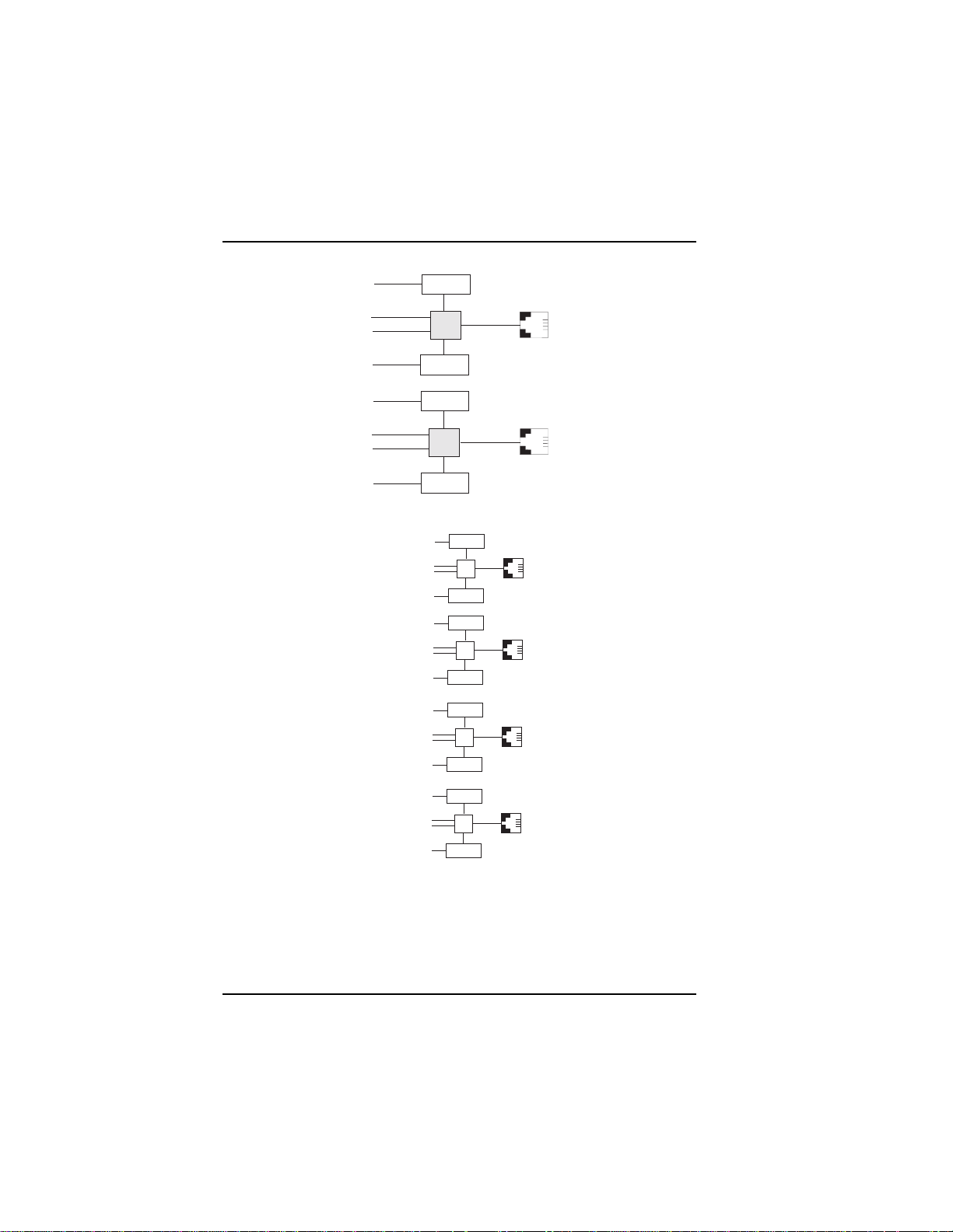
Figure 1-1: Modems and Terminal Adapters of ISIHP-2S/2U
9
Modem
1
2
Modem
10
11
Modem
3
4
Modem
12
13
Modem
5
6
Modem
14
RJ-45 Jack
TA
TA
TA
3456
RJ-45 Jack
3456
RJ-45 Jack
3456
15
Modem
7
8
Modem
16
RJ-45 Jack
TA
3456
Figure 1-2: Modems and Terminal Adapters of ISIHP-4S/4U (for ISIHP-4SD, no
modems are present)
6 MultiModemISI Hybrid Series, ISIHP-2S/2U/4S/4U/4SD
Page 7

Introduction
From the perspective of the server PC, the ISIHP-2S/2U is an eightport serial card with eight devices permanently attached to the serial
ports (Figure 1-1). The first four ports are the two terminal adapters,
each of which appear as two ports. The remaining four ports are the
four central site modems. The following chart summarizes the
correlation of ports and devices.
2S/2U Port # Device ISDN Line Number
1TA 1
2TA 1
3TA 2
4TA 2
5 Modem 1
6 Modem 1
7 Modem 2
8 Modem 2
From the perspective of the server PC, the ISIHP-4S/4U is an sixteenport serial card with sixteen devices permanently attached to the serial
ports (Figure 1-2). The first eight ports are the four terminal adapters,
each of which appear as two ports. The remaining eight ports are the
eight central site modems. The following chart summarizes the
correlation of ports and devices. The ISIHP-4SD contains terminal
adapters only; no modems are present.
MultiModemISI Hybrid Series, ISIHP-2S/2U/4S/4U/4SD 7
Page 8

Introduction
4S/4U Port # Device ISDN Line Number
1TA 1
2TA 1
3TA 2
4TA 2
5TA 3
6TA 3
7TA 4
8TA 4
9 Modem 1
10 Modem 1
11 Modem 2
12 Modem 2
13 Modem 3
14 Modem 3
15 Modem 4
16 Modem 4
This ISIHP Quick Start Guide contains installation instructions and
technical support information. Because its written for audiences with
basic PC skills, step-by-step instructions for such basic operations as
logging in and file editing are not included.
Peripiheral Component Interconnect (PCI)
First developed by companies such as IntelTM, AT&TTM and Digital
Equipment CorporationTM, the Peripheral Component Interconnect
(PCI) bus used by your ISIHP card provides high performance and is
easy to use. Because PCI devices contain registers with the device
information required for configuration, full auto configuration of PCI
Local Bus add-in boards and components is supported. Performance
factors include a bus data path of 64 bits, clock speeds of 66 MHz,
and bandwidth of 264 Mbs.
8 MultiModemISI Hybrid Series, ISIHP-2S/2U/4S/4U/4SD
Page 9

Introduction
Communication Protocols for ISIHP Ports
Ports on the ISIHP card can be associated with different protocols, as
follows:
Auto-Protocol. Modem or terminal adapter automatically negotiates
with host to operate using the hosts current protocol.
Central Site Modem. Common designation for analog modems built
into the ISIHP card. These are V.90 modems. For the ISIHP-2S/2U,
the last four modems should be designated as Central-Site modems;
for the ISIHP-4S/4U, the last eight modems should be designated as
Central-Site modems. (See Port/Device table on previous page.)
MultiLink PPP async. This protocol allows the functional bundling
together of three WAN ports so they function as a single highbandwidth data pipeline using only one IP address. Bundling occurs
on demand when the needed bandwidth exceeds that available on a
single circuit.
PPP async. (Point-to Point Protocol, asynchronous) Protocol
allowing computers a dial-up connection to the Internet. PPP includes
error detection, data compression and other improvements over Serial
Line Internet Protocol (SLIP) connections.
V.120. Terminal rate adaptation protocols. These apply to ISDN Bchannels when using a V interface. This protocol includes V.110.
X.75. An international standard that allows X.25 packet-switched
networks to communicate with each other. X.75 is a gateway protocol
for interconnection of X.25 public networks.
MultiModemISI Hybrid Series, ISIHP-2S/2U/4S/4U/4SD 9
Page 10

Introduction
10 MultiModemISI Hybrid Series, ISIHP-2S/2U/4S/4U/4SD
Page 11

Hardware Installation
Hardware
Installation
MultiModemISI Hybrid Series, ISIHP-2S/2U/4S/4U/4SD 11
Page 12

Hardware Installation
Introduction
This section describes how to install the ISIHP server card into the
PCI bus on your personal computer, which involves
Opening your PC
Installing the card into the PC
Computer Requirements
Pentium-based PC or compatible with PCI bus architecture
Microsoft Windows 95, Windows 98, Windows NT version 4.0, SCO
Open Server version 5.0, Novell NetWare, or Linux
At least one floppy drive
800 blocks of hard disk space for UNIX, 100K bytes for Windows
NT, 34K bytes for Windows 95, 50K bytes for Novell
Shipping Contents
ISIHP card
RJ-45 ISDN cords (2 for ISIHP-2S/2U; 4 for ISIHP-4S/4U)
ISIHP Driver Disk set
ISDN TA Configuration Wizard disk
Quick Start Guide
User Guide (this online manual) on CD-ROM
Safety Warnings
Never install telephone wiring during a lightning storm.
Never install telephone jacks in wet locations unless the jacks are
specifically designed for wet locations.
Never touch uninsulated telephone wires or terminals unless the
telephone line has been disconnected at the network interface.
Use caution when installing or modifying telephone lines.
Avoid using a telephone (other than cordless type) during an
electrical storm. There may be a remote risk of electrical shock from
lightning.
12 MultiModemISI Hybrid Series, ISIHP-2S/2U/4S/4U/4SD
Page 13

Hardware Installation
Do not use the telephone to report a gas leak in the vicinity of that
leak.
Ports that are connected to other apparatus are defined as SELV.
To ensure conformity to EN 41003, ensure that these ports are
connected only to the same type on the other apparatus.
Hardware Installation Procedure
1. Before handling the ISIHP card, discharge any static in your body
by touching a piece of grounded metal such as the computer
chassis.
2. Carefully remove the ISIHP card from its antistatic bag, handling it
only by the mounting bracket and edges. Do not touch the goldplated connectors along the bottom edge. (You may want to save
packaging for possible future use.)
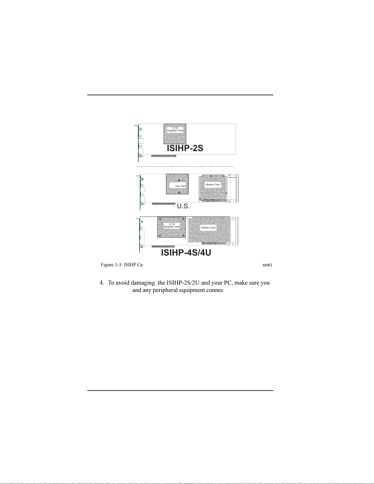
3. Visually inspect the ISIHP-2S/2U/4S/4U/4SD. The 2S and 4SD
models have only one daughter card, whereas the others have two.
If you have any concerns about the condition of your ISIHP unit,
call Technical Support at (612) 717-5863.
MultiModemISI Hybrid Series, ISIHP-2S/2U/4S/4U/4SD 13
Page 14
Hardware Installation
a
a
a
a
a
a
a
aa
a
aa
aaa
a
a
a
a
a
a
a
aa
a
a
aa
a
a
a
a
a
a
a
a
a
aa
a
aa
aa
a
a
a
a
a
a
a
a
aa
a
a
aa
a
a
a
a
a
aa
aa
a
a
a
a
a
a
a
a
a
a
a
a
a
a
a
a
a
a
aa
a
aa
aaa
a
a
a
a
a
a
a
aa
a
a
aa
a
a
a
a
aa
a
aa
aaa
a
a
a
a
a
a
a
aa
a
a
aa
a
a
a
a
a
aa
aa
a
a
a
a
aa
a
a
a
a
a
a
a
a
a
a
a
a
a
a
a
aa
a
a
a
a
a
a
a
a
a
a
a
a
a
a
a
aa
a
aa
aa
a
a
a
a
a
a
a
a
aa
a
a
aa
a
a
a
a
a
aa
Intelligent Serial Interface
Hybrid (ISDN/POTS) Cards
(
Side View
V.11 0
Daughter Card
ISIHP-2S
International
)
V.11 0
Daughter Card
ISIHP-2U
U.S. Domestic
V.11 0
Daughter Card
ISIHP-4S/4U
Figure 1-3: ISIHP Cards; Side View (on ISIHP-4SD, right daughter card is not present)
4. To avoid damaging the ISIHP-2S/2U and your PC, make sure your
computer and any peripheral equipment connected to it are turned
off. The ISIHP-2S/2U can be installed in a Pentium equivalent
PCI bus computer.
5. Remove the cover of your computer as instructed in your
computers documentation.
6. Locate the unused PCI slot you will be using for your ISIHP-2S/2U
card and remove the slot cover according to instructions in your
computers documentation.
7. Install the ISIHP-2S/2U card in the selected expansion slot in the
same manner as any other add-on card according to your
computers documentation.
8. Fasten retaining bracket to computer chassis and replace the cover.
Modem Card
Modem Card
14 MultiModemISI Hybrid Series, ISIHP-2S/2U/4S/4U/4SD
Page 15
Hardware Installation
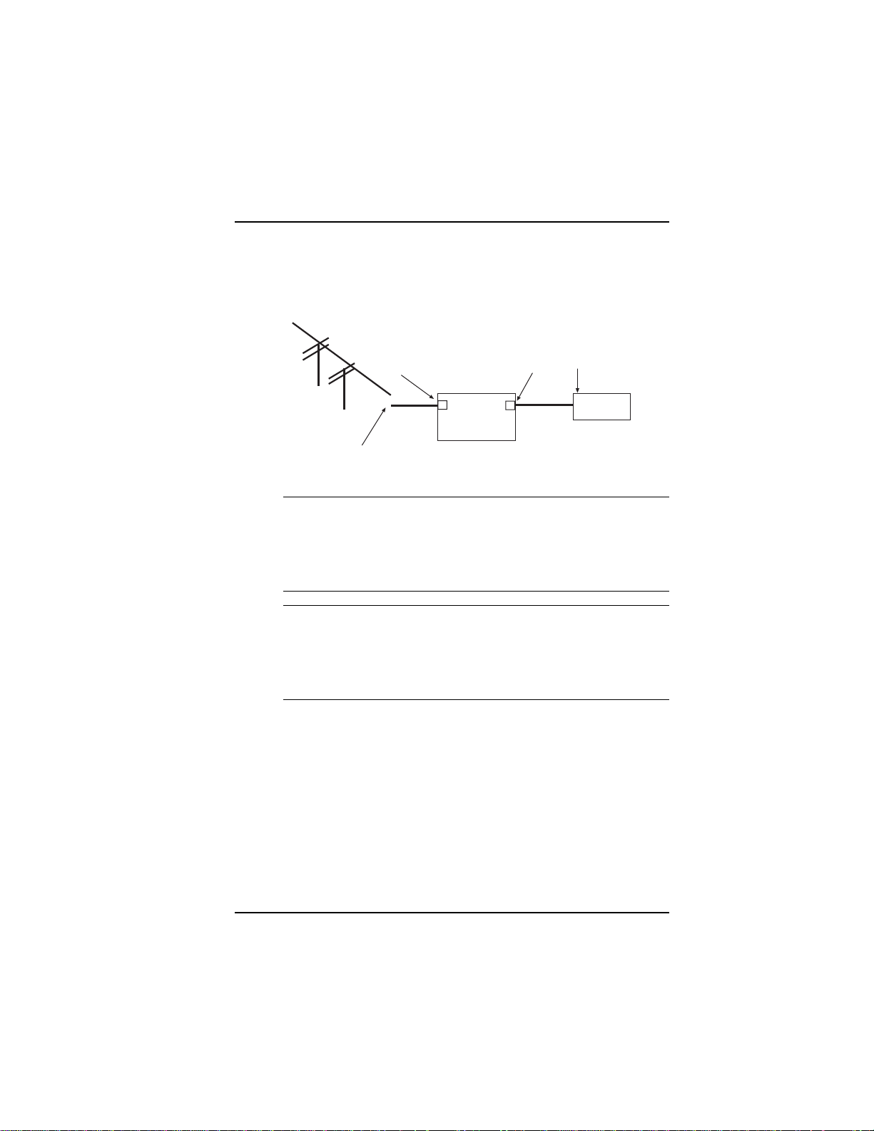
9. Connect the ISIHP-2S/2U to your ISDN telephone wall jack with
the provided modular telephone cable.
S/T Interface
ISIHP
-2S
NT1
Device
S Interface
U Interface
ISDN line enters
building
Figure 1-4: ISDN Interfaces at Customer Premises
Note: The ISIHP communicates over ISDN lines. If you dont have
a standard modular jack near your computer, you should install
one or have one installed by your telephone company. In the US,
installation kits and adapters are available wherever telephones
are sold.
Note: If S/T-interface ISDN network connection cable is used, the
ISDN phone cord should be connected between the ISDN network
connection cable and the NT1 device. If the S/T-interface model
(ISIHP-2S, -4S, or 4SD) is used, then the S/T-interface must be
connected to the S-interface on the NT1 device.
10. Turn on power to the computer. Now you are ready to install
software.
MultiModemISI Hybrid Series, ISIHP-2S/2U/4S/4U/4SD 15
Page 16
Hardware Installation
LED Indicators
The mounting brackets for the four ISIHP cards are similar, but the LEDs
are labeled differently. Below, and on the next page, are graphics for each
bracket along with descriptions of the LED indicators.
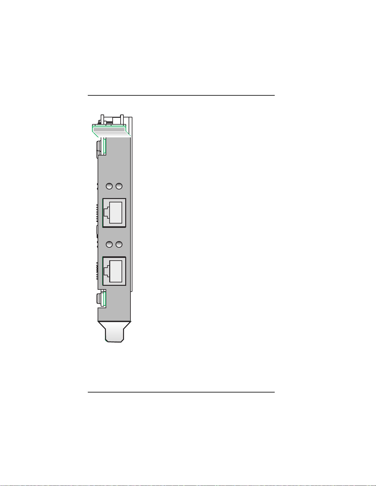
ISIHP-4U LEDs (one LED per BRI)
Flashes between OFF and RED to
indicate that neither SPID for that ISDN
1
3
LINE 1
2
4
Line 1
Line 2
ISIHP-4S/4SD LEDs (one LED per
Line 3
Line 4
BRI)
line has been verified.
Flashes between RED and GREEN to
indicate that one SPID is correct.
A solid GREEN display indicates that
both SPIDs are correct.
Solid GREEN indicates normal
operation.
Flashes between RED and GREEN to
indicate that the device has been reset.
16 MultiModemISI Hybrid Series, ISIHP-2S/2U/4S/4U/4SD
Page 17
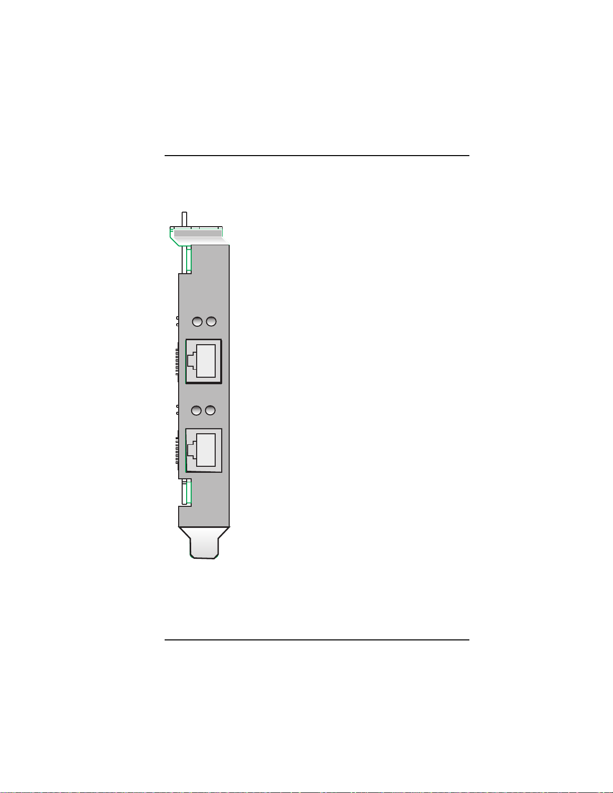
ISIHP-2S LED Indicators
B1 LED Indicator
When lit, indicates active or voice connection on
B-channel 1.
When lit, indicates active or voice connection on
B-channel 2.
B1
B2
LINE 1
B1
B2
LINE 2
Hardware Installation
MultiModemISI Hybrid Series, ISIHP-2S/2U/4S/4U/4SD 17
Page 18
Hardware Installation
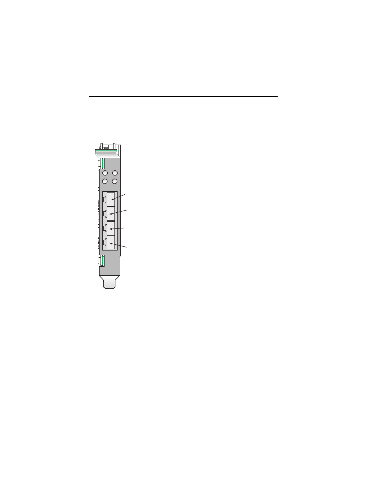
ISIHP-2U LED Indicators
P LED Indicator
Indicates U interface status connection.
Controlled by NT-1, which converts S/T
interface (4-wire ISDN) to U interface
(2-wire ISDN).
D
P
LINE 1
D
P
LINE 2
When U interface and S/T interface are NOT
active, LED remains off.
Flashes 8 times/second (8 Hz)U interface
is attempting to activate.
Flashes once/second (1 Hz)U interface is
active; S/T interface is not fully active.
Lit, not flashingBoth U and S/T interfaces
are active.
D LED Indicator
Lights when the ISIHP-2S/2U is turned on.
Flashes until SPIDs are verified with the
central office switch; then remains lit without
flashing.
Indicates data link layer status.
18 MultiModemISI Hybrid Series, ISIHP-2S/2U/4S/4U/4SD
Page 19

Software/Driver Installation
Software
Installation
MultiModemISI Hybrid Series, ISIHP-2S/2U/4S/4U/4SD 19
Page 20
Software/Driver Installation (Windows NT)
Installing the ISIHP in Windows NT 3.51/4.0
The following procedure describes how to install the ISIHP card in a
system operating Microsoft Windows NT 3.51 or 4.0 for use with
Remote Access Service (RAS) server and other communications/fax
server type applications. These procedures refer to both 3.51 and 4.0.
1. Install the ISIHP in an available PCI slot as described in the
installation section of this manual.
2. Turn on the computer.
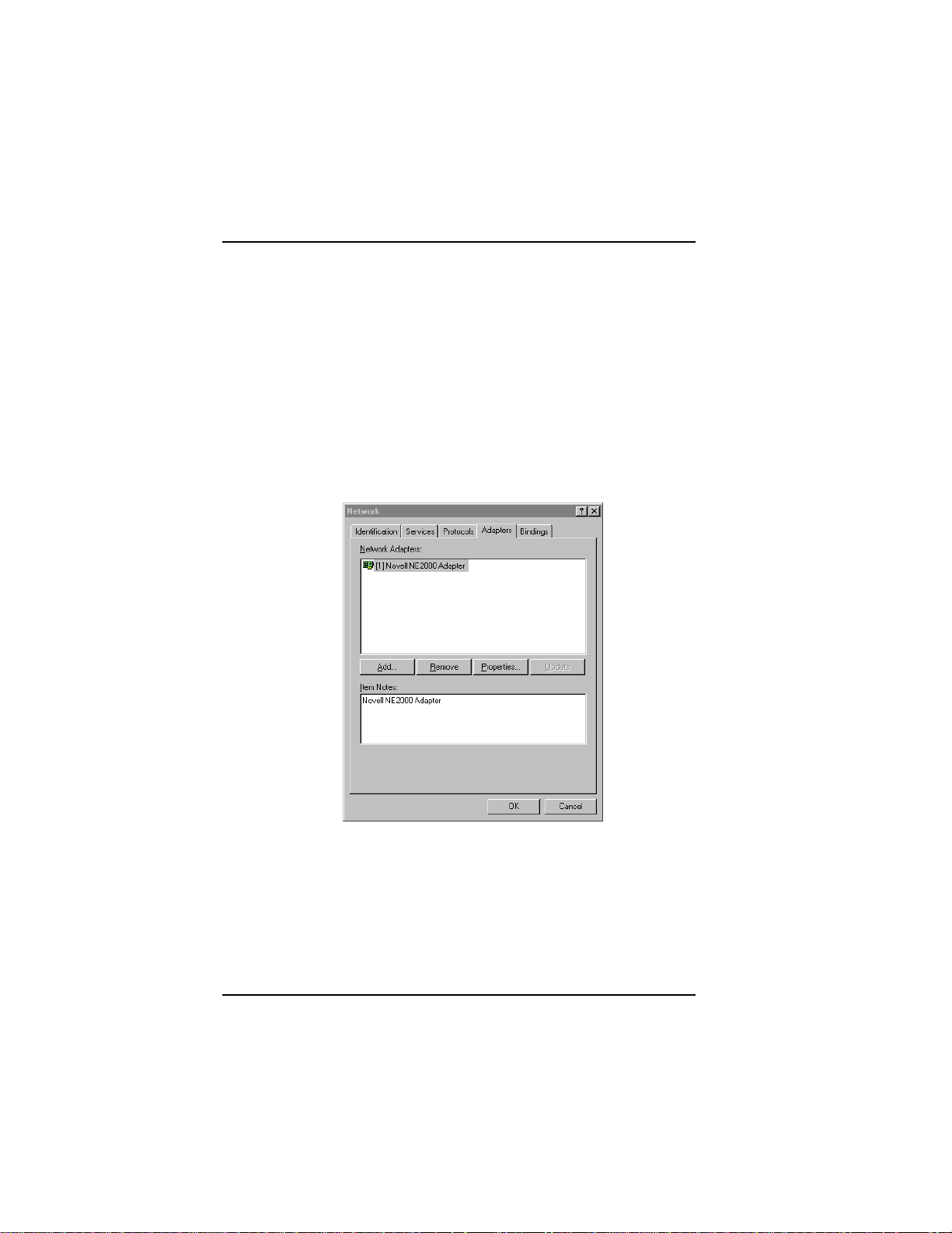
3. Click Start, Settings, Control Panel, and then double-click
Network. In the Network dialog box, click the Adapters tab. Then
click Add.
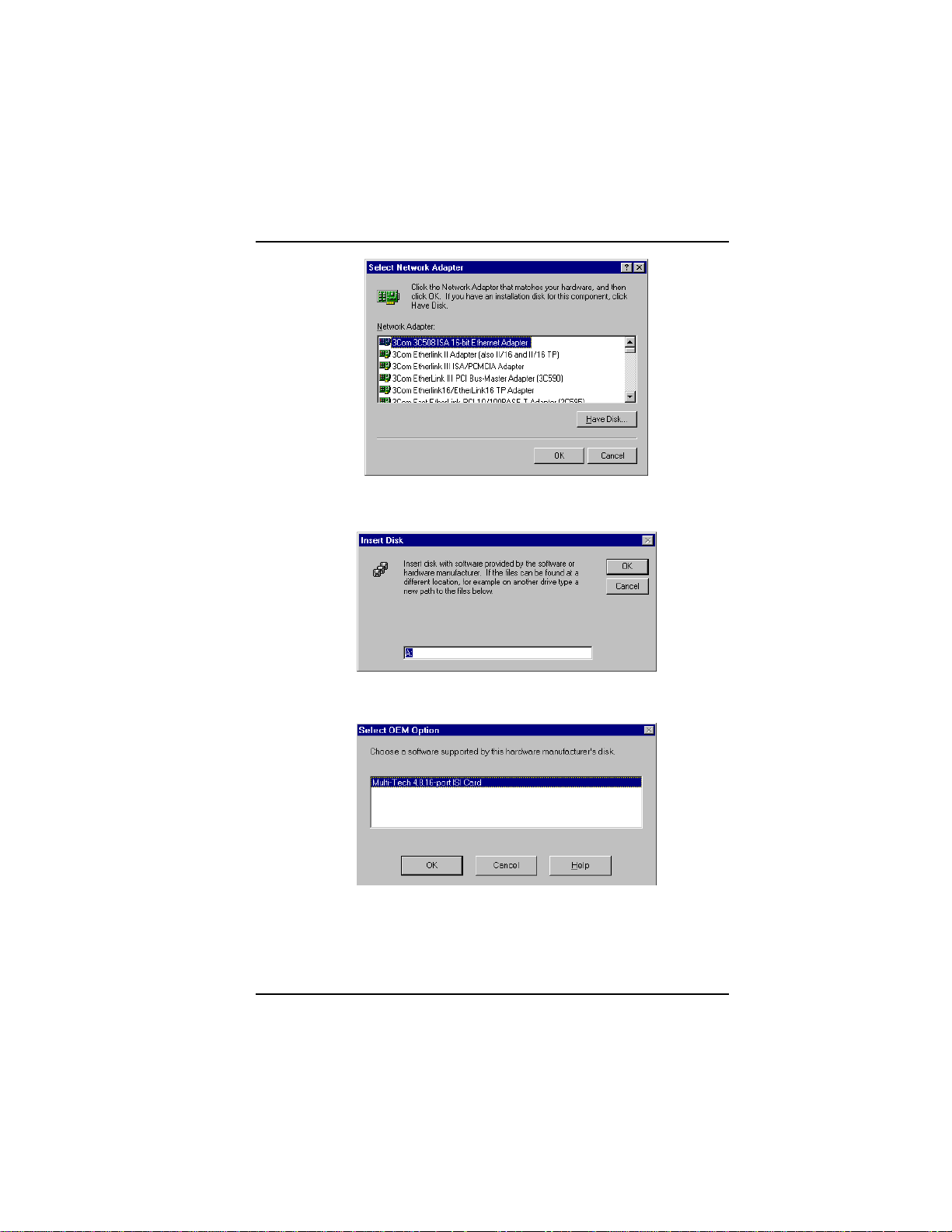
4. The Select Network Adapter dialog box appears. Click Have
Disk.
20 MultiModemISI Hybrid Series, ISIHP-2S/2U/4S/4U/4SD
Page 21
Software/Driver Installation (Windows NT)
5. The Insert Disk dialog box appears. Insert the MultiModem ISI
Driver for Windows NT diskette and click OK.
6. The Select OEM Option dialog box appears. Click OK.
MultiModemISI Hybrid Series, ISIHP-2S/2U/4S/4U/4SD 21
Page 22
Software/Driver Installation (Windows NT)
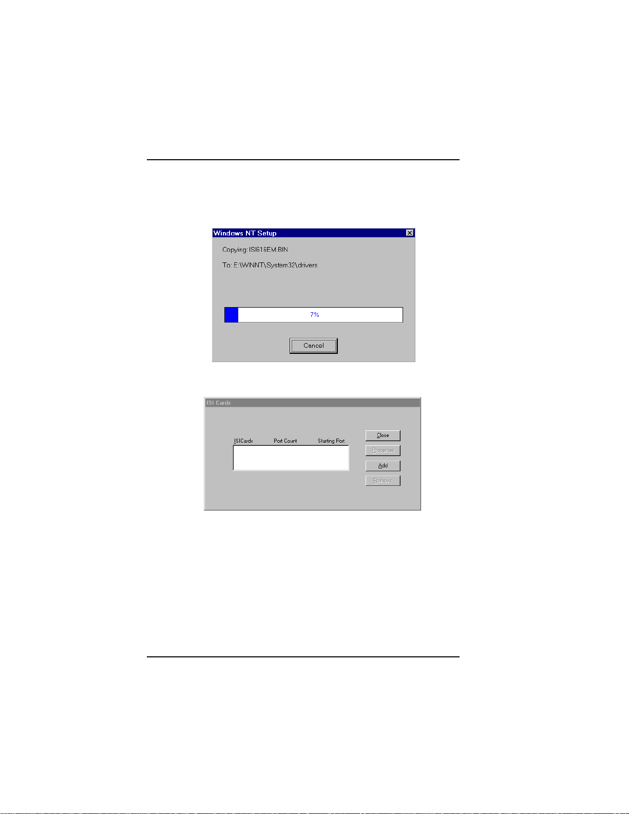
A transient dialog box will appear while the setup program is
loaded from the diskette to the PC hard drive.
7. The ISI Cards dialog box appears. Click Add.
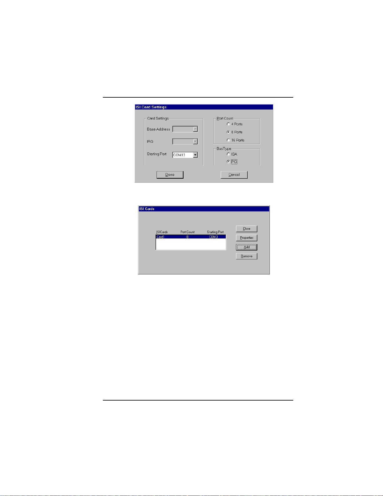
8. Then this ISI Cards dialog box appears. Select the starting port
(usually port 3).
22 MultiModemISI Hybrid Series, ISIHP-2S/2U/4S/4U/4SD
Page 23
Software/Driver Installation (Windows NT)
9. The ISI Cards dialog box appears again showing the port
assignment. Click Add to add additional cards and repeat step 8.
After the last ISIHP card has been added, click Close.
MultiModemISI Hybrid Series, ISIHP-2S/2U/4S/4U/4SD 23
Page 24
Software/Driver Installation (Windows NT)
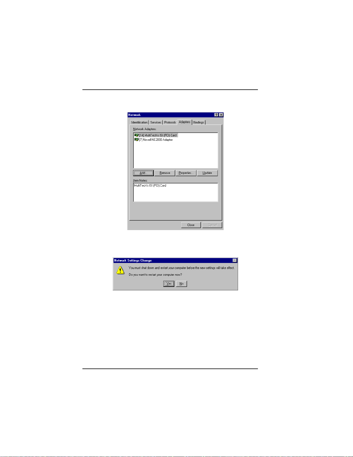
10. The file copies and Multi-Tech ISIHP Adapter appears in the
Network Adapters box. Click Close.
11. When this dialog box appears, click Yes to reboot your system.
The ISIHP-2S/2U now is installed in Windows NT.
Installing T As & Modems to COM Ports in W indows NT
To install terminal adapters:
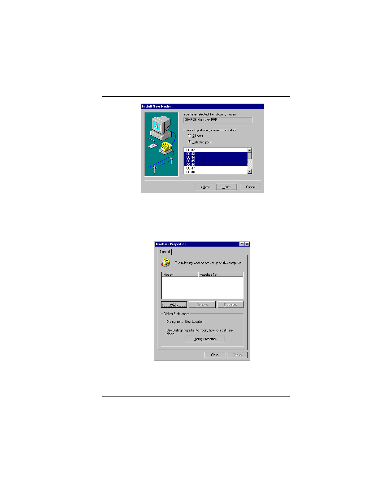
1. In the Control Panel, double-click the Modems icon.
2. The Modem Properties dialog box appears. Click Add.
24 MultiModemISI Hybrid Series, ISIHP-2S/2U/4S/4U/4SD
Page 25
Software/Driver Installation (Windows NT)
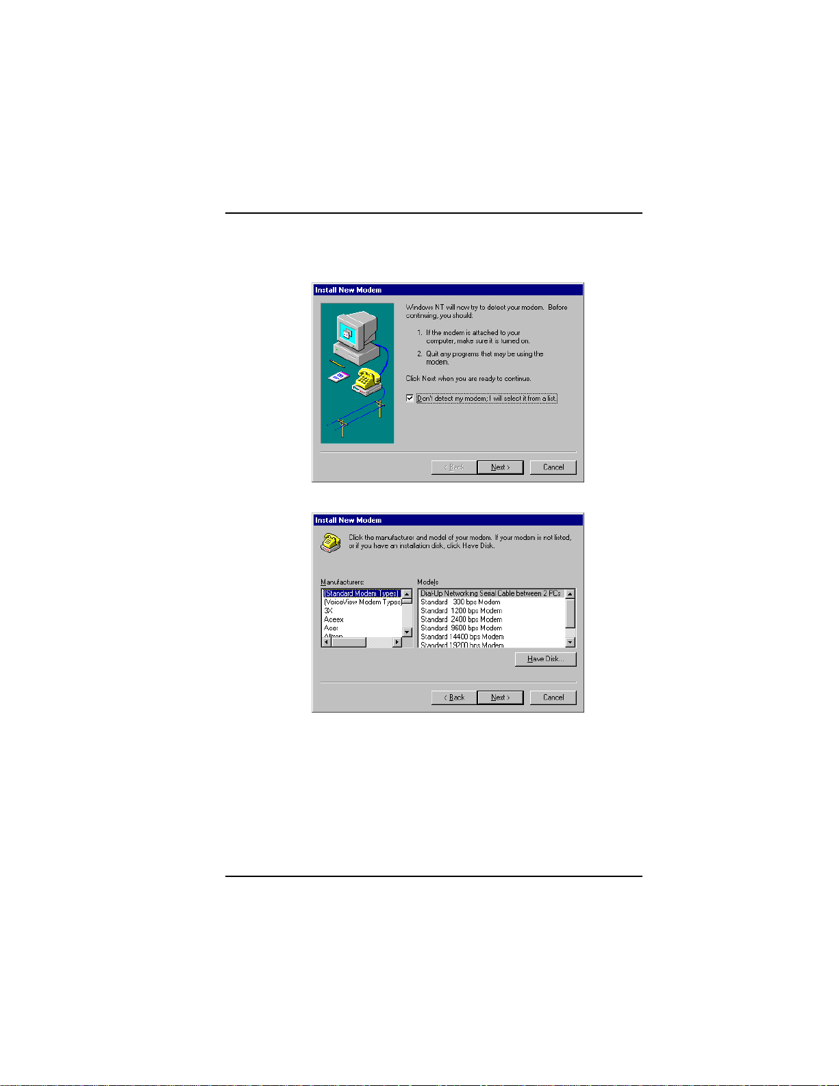
3. The Install New Modem dialog box appears. Check the box
marked Don't detect my modem; I will select it from a list and
click Next.
4. The Install New Modem dialog box appears. Click Have Disk.
MultiModemISI Hybrid Series, ISIHP-2S/2U/4S/4U/4SD 25
Page 26
Software/Driver Installation (Windows NT)
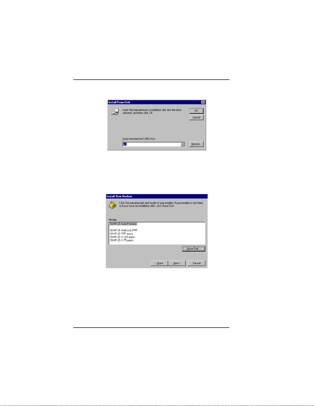
5. The Install From Disk dialog box appears. Click OK (diskette
should still be in drive).
6. The Install New Modem dialog box appears. From the Models
list, select an ISDN protocol (Auto-Protocol, ML-PPP, PPP, V.120,
or X.75, depending on your application). ( See description of
protocols in the Introduction chapter of this manual.) Then click
Next.
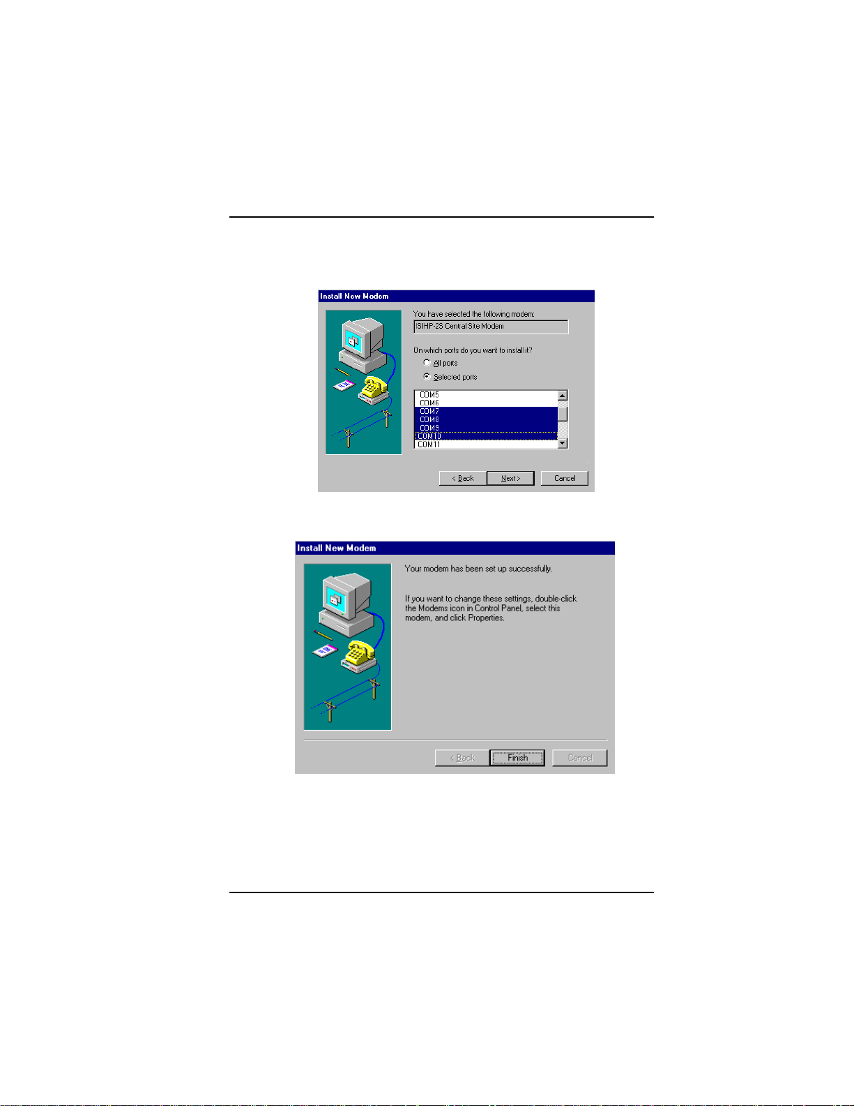
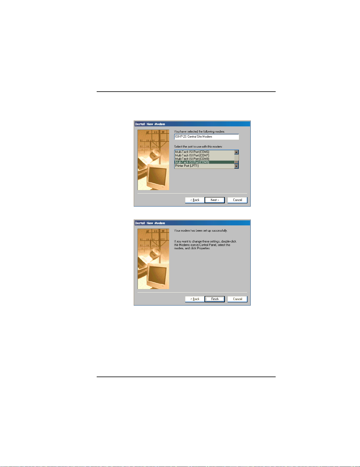
7. The Install New Modem dialog box appears. Select the ports that
correspond to the first four ports of the ISIHP-2S/2U card, OR the
first eight ports of the ISIHP-4S/4U . Any ports that existed prior
to installing the ISIHP appear first in the list of available COM
ports. Click Next. The terminal adapters (screen displays modems)
install to the selected COM ports.
26 MultiModemISI Hybrid Series, ISIHP-2S/2U/4S/4U/4SD
Page 27
Software/Driver Installation (Windows NT)
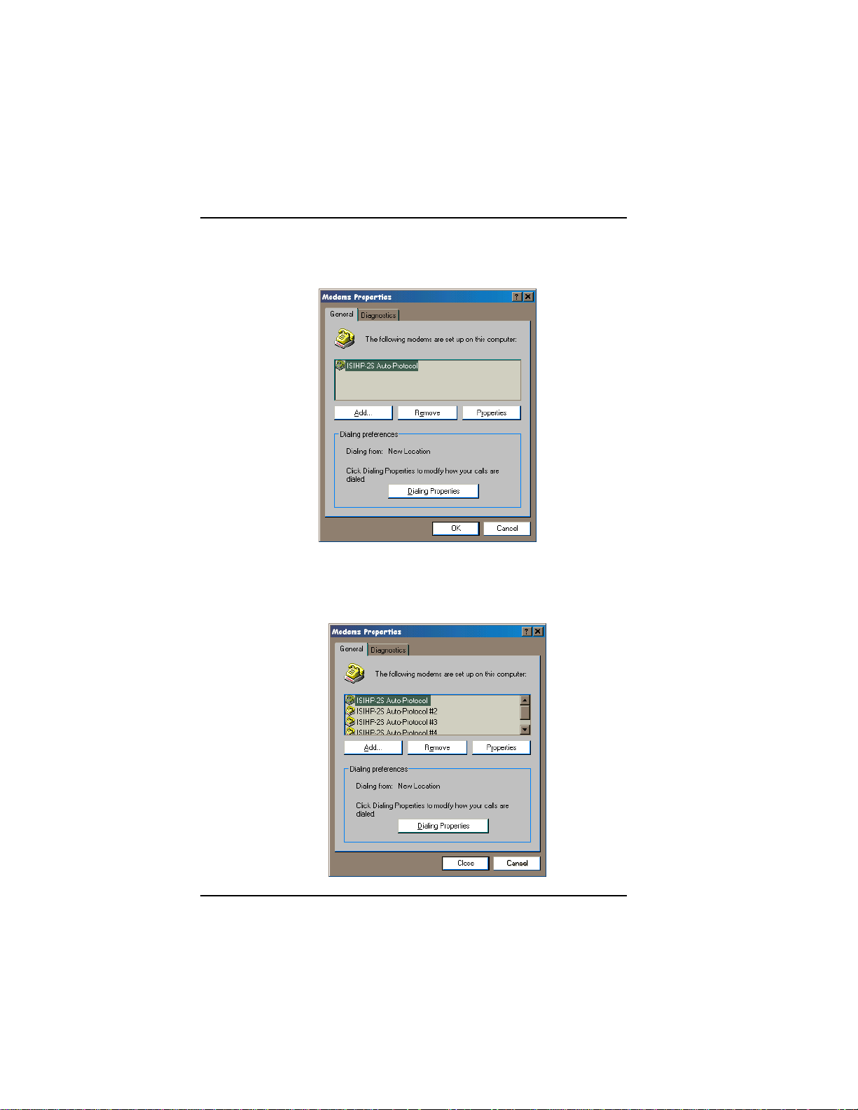
8. After the terminal adapters install, click Finish to return to the
General tab to view COM port assignments (and make changes if
necessary). Now you are ready to install the modems.
To install modems:
1. In the General tab, click Add.
{does not apply to -4SD}
MultiModemISI Hybrid Series, ISIHP-2S/2U/4S/4U/4SD 27
Page 28
Software/Driver Installation (Windows NT)
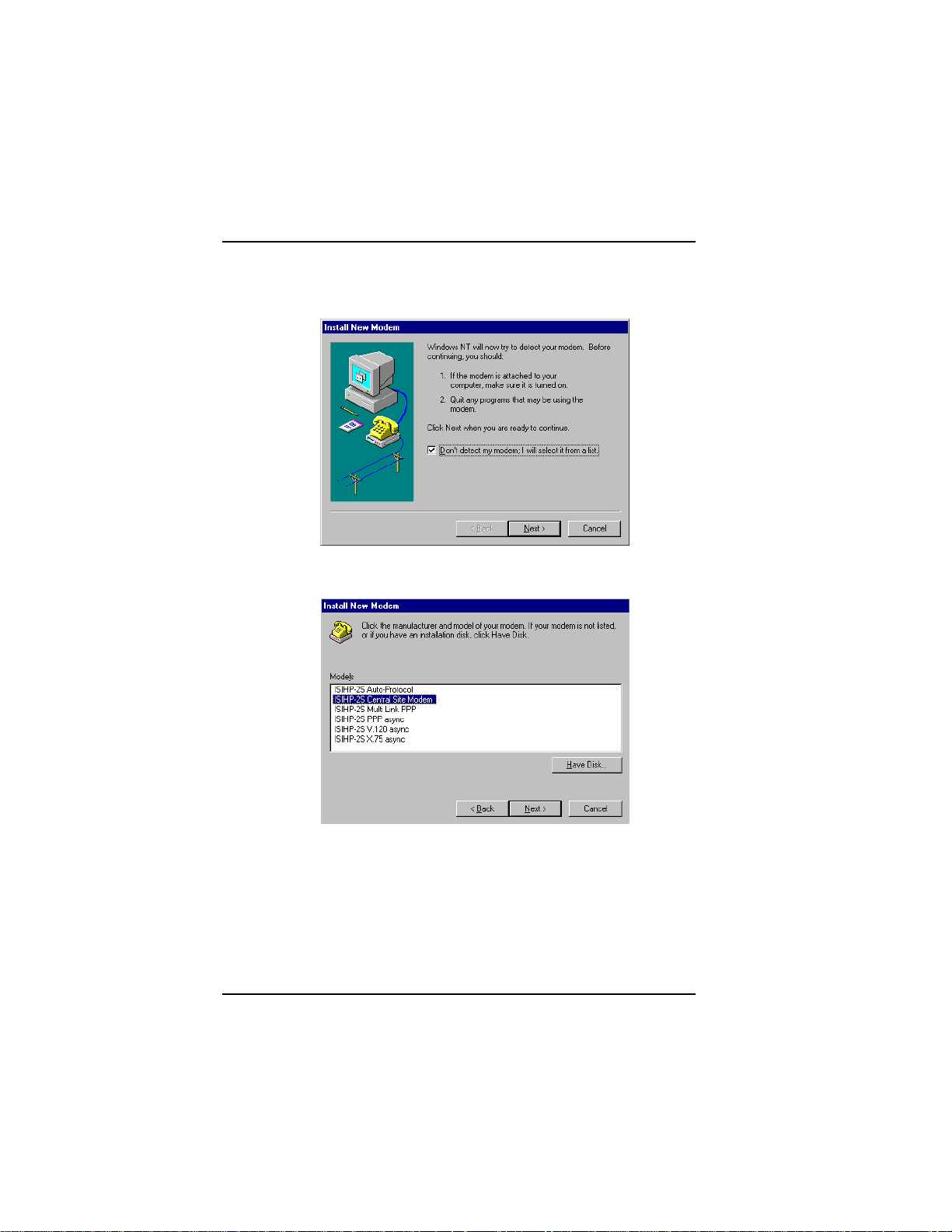
2. The Install New Modem dialog box appears. Check the box
marked Don't detect my modem; I will select it from a list. Then
click Next.
3. The Install New Modem dialog box appears. From the Models
list, select Central Site Modems for the modems. Then click Next.
28 MultiModemISI Hybrid Series, ISIHP-2S/2U/4S/4U/4SD
Page 29
Software/Driver Installation (Windows NT)
4. Select the ports that correspond to the last four ports of the ISIHP2S/2U card OR the last eight ports of the ISIHP-4S/4U card. Click
Next. The modems install to the selected COM ports.
5. After the modems install to the ports, click Finish to return to the
General tab.
MultiModemISI Hybrid Series, ISIHP-2S/2U/4S/4U/4SD 29
Page 30
Software/Driver Installation (Windows NT)
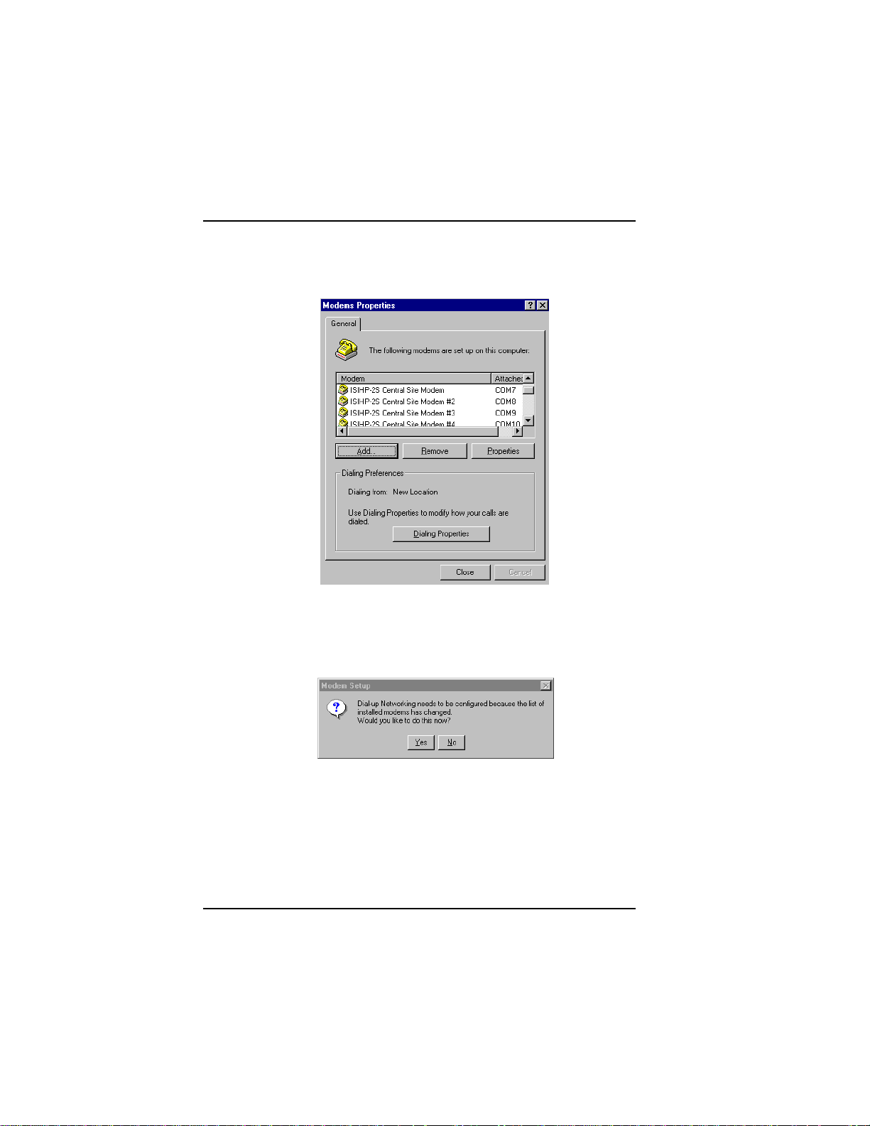
6. To view COM port assignments and make necessary changes, use
the Modem Properties dialog box.
7. Close the Modems Properties dialog box. The message below
appears asking if you want to configure dial-up networking. Click
Ye s .
30 MultiModemISI Hybrid Series, ISIHP-2S/2U/4S/4U/4SD
Page 31
Software/Driver Installation (Windows NT)
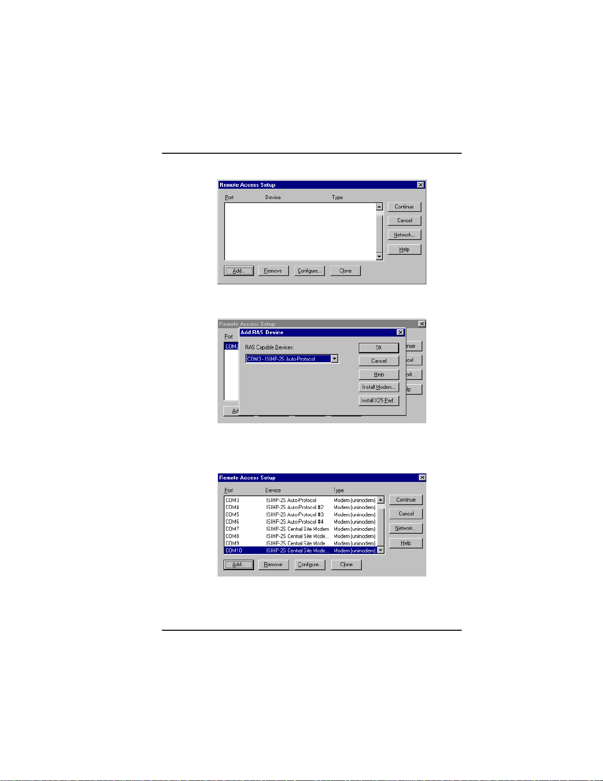
8. The Remote Access Setup dialog box appears. Click Add.
9. Each COM port appears in a separate Add RAS Device dialog box.
To add the highlighted device, click OK.
10. The Remote Access Setup dialog box displays again. Repeat steps
7 and 8 until all devices are added.
11. When all devices have been added, click Continue.
MultiModemISI Hybrid Series, ISIHP-2S/2U/4S/4U/4SD 31
Page 32

Software/Driver Installation (Windows NT)
n
12. After the bindings have been reviewed and stored, the message
below appears, click Ye s .
After re-booting, the ISI Cards icon appears in the Control Panel.
ico
You are now ready to configure the terminal adapter. See the
section,Configuring the Terminal Adapter, on page 49.
I/O Addresses and IRQ Codes
Unlike many modem products, the ISIHP has no DIP switch for I/O
addresses and no jumper to determine the IRQ code. The input/output
address and the interrupt request code (IRQ) for the ISIHP are
assigned automatically during driver installation. During any
subsequent re-cofiguring of your PC, you may need to know the
assigned I/O address and IRQ code. To determine the I/O address
and IRQ assigned to the ISIHP:
32 MultiModemISI Hybrid Series, ISIHP-2S/2U/4S/4U/4SD
Page 33

Software/Driver Installation (Windows NT)
(for Windows NT) click on Start, Settings, Control Panel and select
the ISI Cards icon; or click on Start, Programs, Administrative
Tools (Common), Windows NT Diagnostics, Resources;
(for Windows 95) click on Start, Settings, and Control Panel. From
the Control Panel, click on System icon and then the Device
Manager tab. From there, click on the Computer icon at the top
of the Device Manager window. The Computer Properties
dialog box will appear. In the View Resources tab, click on either
the Interrupt Request (IRQ) or Input/Output (I/O) radio buttons
to view lists of both the IRQs and I/O memory addresses in use in
the computer and what devices are currently using these resources.
Removing ISIHP Card and Driver in Windows
NT 3.51/4.0
1. Click Start, Settings, Control Panel, and then double-click
Network.
2. The Network dialog box appears. Click the Adapters tab.
3. Select Multi-Tech PCI ISI Card, and then click Remove.
Note: To complete an uninstall, reboot your system.
MultiModemISI Hybrid Series, ISIHP-2S/2U/4S/4U/4SD 33
Page 34
Software/Driver Installation (Windows 95/98)
Installing the ISIHP in Windows 95 and Windows 98
This section describes how to install the ISIHP in systems operating
Microsoft Windows 95 or Windows 98 to use with a Remote Access
Service (RAS) server and other communications/fax server type
applications.
Windows 95 Installation
1. After installing the ISIHP in an available PCI slot, turn on the
computer.
2. Windows 95 automatically detects the ISIHP card. A dialog box
appears saying that Windows has found the new hardware and is
locating the software for it.
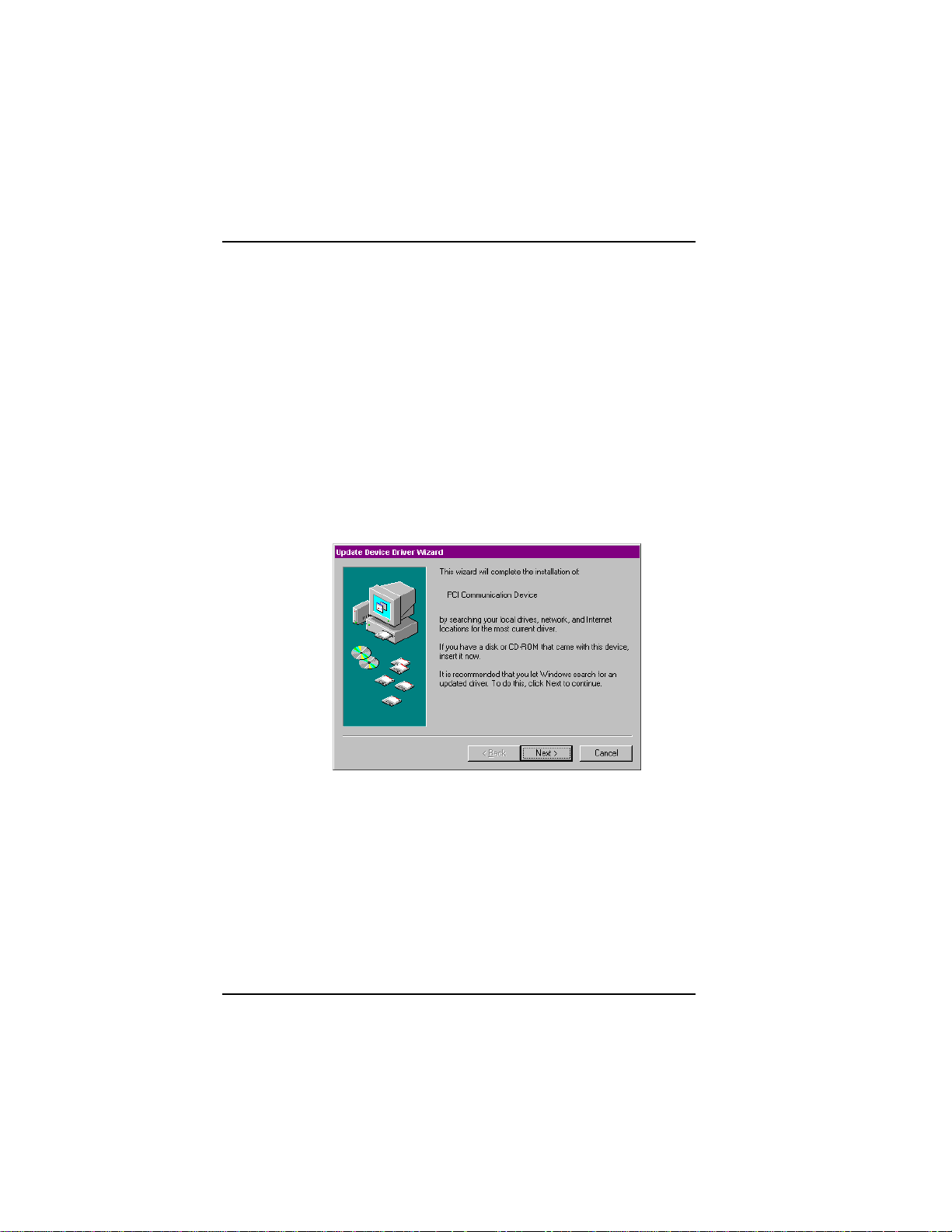
3. The Update Device Driver dialog box appears. Insert the ISIHP
Windows 95 driver diskette and click Next.
4. Windows 95 automatically searches for the unknown device and
locates the MultiTech ISI Port. After the operating system goes
through this process for every port added, click Finish.
34 MultiModemISI Hybrid Series, ISIHP-2S/2U/4S/4U/4SD
Page 35

Software/Driver Installation (Windows 95)
5. To view the COM ports, click Control Panel and double-click
System. In the System Properties dialog box in Device Manager,
the MultiTech PCI ISI Card appears under Multi Port. To view
ports, click Ports (COM & LPT). Click OK to close.
MultiModemISI Hybrid Series, ISIHP-2S/2U/4S/4U/4SD 35
Page 36

Software/Driver Installation (Windows 95)
To Remove the ISIHP Card &Drivers in Windows 95
To remove the ISIHP card:
1. Click Start, Settings, Control Panel, and then System.
2. The System Properties dialog box appears. Click the Device
Manager tab.
3. Click Multi Port Adapter and select MultiTech PCI ISI Card,
and then click Remove.
To remove the drivers:
1. Click Start, Settings, Control Panel, and then double-click Add/
Remove Programs.
2. Select MultiTech ISI Card and then click Add/Remove.
Note: To complete an uninstall, reboot your system.
Windows 98 Installation
1. After installing the ISIHP card in an available PCI slot, turn on the
computer.
2. Windows 98 automatically detects the ISIHP card. A dialog box
appears saying that Windows has found the new hardware and is
locating the software for it.
3. The Add New Hardware Wizard dialog box appears.
Click Next.
36 MultiModemISI Hybrid Series, ISIHP-2S/2U/4S/4U/4SD
Page 37

Software/Driver Installation (Windows 98)
4. In the next Wizard dialog box, select Search for the best driver
for your device. (Recommended). Then click Next.
5. In the next Wizard dialog box, make sure Floppy disk drives is
checked. Insert the MultiModem ISI Driver for Windows 95/98
diskette. Then click Next and the system locates the file.
MultiModemISI Hybrid Series, ISIHP-2S/2U/4S/4U/4SD 37
Page 38

Software/Driver Installation (Windows 98)
6. When this Wizard dialog box appears, click Next.
7. Windows then installs the device driver for the ISIHP card. When
this dialog box appears, click Finish.
Windows 98 will now detect and create COM ports (for ISIHP-
2S/2U/4SD, 8 ports are made; for ISIHP-4S/4U 16 ports are
made).
8. After the COM parts have been created, you must re-boot your PC
(remove the diskette from the floppy drive before re-booting).
9. To view the COM ports, click Control Panel and double-click
System. The System Properties dialog box appears.
38 MultiModemISI Hybrid Series, ISIHP-2S/2U/4S/4U/4SD
Page 39

Software/Driver Installation (Windows 98)
The MultiTech PCI ISI Card is located under Multi Port Adapter.
Click Ports (COM & LPT) to view the ports. Click OK to close.
To Remove the ISIHP Card and Drivers in
Windows 98
To remove the ISIHP card:
1. Re-boot your computer.
2. Click Start, Settings, Control Panel, and then System.
3. The System Properties dialog box appears . Click the Device
Manager tab.
4. Click Multi Port Adapter and select MultiTech ISIHP-2S/2U
2BRI/4 56K Hybrid Card. Then click Remove.
To remove the drivers:
1. Click Start, Settings, Control Panel, and then double-click Add/
Remove Programs.
MultiModemISI Hybrid Series, ISIHP-2S/2U/4S/4U/4SD 39
Page 40

Software/Driver Installation (Windows 98)
2. Select MultiTech ISI Card and then click Add/Remove.
Installing TAs & Modems to COM Ports in Windows
95 /98
To install terminal adapters:
1. Click Start, Settings, Control Panel, and then double-click the
Modems icon.
2. If no modems are currently installed, the Install New Modem
dialog box appears. Check the box marked Don't detect my
modem; I will select it from a list. Then click Next.
If other modems have been installed, the Modems Properties
dialog box will appear.
40 MultiModemISI Hybrid Series, ISIHP-2S/2U/4S/4U/4SD
Page 41

Software/Driver Installation (Windows 98)
Click Add and the Install New Modem dialog box will appear.
Check the box marked Don't detect my modem; I will select it
from a list. Then click Next.
3. The Install New Modem dialog box appears. Insert diskette
labeled MultiModem ISI Driver for Windows 95 & Netware AIO
and click Have Disk.
MultiModemISI Hybrid Series, ISIHP-2S/2U/4S/4U/4SD 41
Page 42

Software/Driver Installation (Windows 98)
4. The Install From Disk dialog box appears. Click OK.
5. The Install New Modem dialog box appears. Select a protocol
(depending on your application) from the Models list; then click
Next.
6. The Install New Modem dialog box appears. Select the port that
corresponds to the lowest numbered port of the ISIHP card. Any
ports that had been installed before installing the ISIHP card are
numbered lower than the ports of the ISIHP card. Click Next.
42 MultiModemISI Hybrid Series, ISIHP-2S/2U/4S/4U/4SD
Page 43

Software/Driver Installation (Windows 98)
7. Windows will install the first terminal adapter. Click Next.
MultiModemISI Hybrid Series, ISIHP-2S/2U/4S/4U/4SD 43
Page 44
Software/Driver Installation (Windows 98)
8. After the terminal adapter installs, click Finish to return to the
General tab to view COM port assignments (and make changes if
necessary).
9. Click Add and repeat installation steps 28 to install terminal
adapters to the first four ports of the ISIHP-2S/2U (OR the first
eight ports of the ISIHP-4S/4U/4SD). After the terminal
adaptershave been installed, you are ready to install the modems.
44 MultiModemISI Hybrid Series, ISIHP-2S/2U/4S/4U/4SD
Page 45

Software/Driver Installation (Windows 98)
To install modems (Windows 95/98):
1. In the General tab, click Add.
2. The Install New Modem dialog box appears. Check the box
marked Don't detect my modem; I will select it from a list. Then
click Next.
{not applicable to -4SD}
MultiModemISI Hybrid Series, ISIHP-2S/2U/4S/4U/4SD 45
Page 46

Software/Driver Installation (Windows 95/98)
3. The Install New Modem dialog box appears. Insert the driver
diskette labeled MultiModem ISI Driver for Windows NT. Then
click Have Disk.
4. The Install from Disk dialog box appears. Click OK.
5. The Install New Modem dialog box appears. From the Models
list, select Central Site Modems for the modems. Then click Next.
46 MultiModemISI Hybrid Series, ISIHP-2S/2U/4S/4U/4SD
Page 47
Software/Driver Installation (Windows 95/98)
6. The Install New Modem dialog box appears. Select the
numbered port corresponding to the first modem of the ISIHP
card. Click Next. The modem installs to the COM port.
7. After the modem installs to the port, click Finish.
MultiModemISI Hybrid Series, ISIHP-2S/2U/4S/4U/4SD 47
Page 48

Software/Driver Installation (Windows 95/98)
8. Return to the General tab to view COM port assignments (and
make changes if necessary).
9. Click Add and repeat installation steps 28 to install modems to the
last three ports of the ISIHP-2S/2U (OR the last seven ports of the
ISIHP-4S/4U).
Now you are ready to configure the terminal adapters.
48 MultiModemISI Hybrid Series, ISIHP-2S/2U/4S/4U/4SD
Page 49

Software/Driver Installation (Windows 95/98)
Removing the Driver (Windows 95 only)
1. Click Settings, Control Panel, and then double-click Add/
Remove Programs.
2. From the list box, select ISICOM Driver.
3. Click Add/Remove and follow screen instructions.
Configuring the Terminal Adapter
Introduction
North American users must configure the terminal adapter to match
network switch type, the service profile identifier (SPID), and the
directory number (DN). For international users, the terminal adapter
ships already configured for NET3, which should work on most phone
lines in Europe. However, you may want to customize settings,
regardless of your location. (See Optional Settings on the following
page.)
You can configure the terminal adapters with the ISDN TA
Configuration utility, ConfigMenu, or with AT commands.
Instructions for all three are provided in this section.
ISDN TA Configuration Utilityrecommended for computers with
Windows 95/98 and Windows NT.
ConfigMenurecommended for computers with DOS or Windows
3.x and a VT100/ANSI compatible terminal or data communication
program that includes VT100/ANSI terminal emulation.
AT Commandsallow you to fine tune TA operation with AT
commands and S-registers. Enter these commands in your data
communication programs terminal mode. AT commands are
described in detail in the online manual.
North American Users
Before you connect the ISIHP-2S/2U to your network terminator, you
must configure it to match the following:
Network Switch Type ____________________
Select the network switch type your ISDN service uses at its local
MultiModemISI Hybrid Series, ISIHP-2S/2U/4S/4U/4SD 49
Page 50

Software/Driver Installation (Windows 95/98)
central office. You can set the TA to NET3, AT&T 5ESS, NT DMS100, or US National ISDN-1. If you don't know the switch type, get
the information from the local phone company. AT command: !CO=
SPIDs and DNs ________________________
The TA must be configured with the Service Profile Identifier
(SPID). The SPID, assigned by the local phone company, is for the
specific BRI line where TA is attached. The SPID field is empty prior
to configuration. AT command: AT!C6= and AT*!C6
The Directory Number (DN) is the phone number another user would
call to contact this TA once it is attached to the ISDN. AT commands:
AT!N1= and AT*!N1=
Note: SPIDs only apply for North American switch types.
International Users
The terminal adapters ship already configured for NET3, which should
work for most telephone lines in Europe. If you want to customize
settings, refer to the Optional Settings below.
Optional Settings
Data TEI _____________________________
The Data TEI is the TEI (terminal endpoint identifier) assigned to the
data channel. You can select Auto TEI, a fixed TEI, or Disable. A
TEI is a number used by the central office switch to uniquely identify
each device that is connected to the network. When it uses dynamic
TEI assignments (Auto TEI), the central office switch assigns a TEI
each time the TA connects to the network. However, the ISDN
service provider may assign a fixed TEI at subscription time, in
which case you must configure the TA with the fixed TEI number.
You also can disable the channel, which may be useful when multiple
TAs are attached to a network terminator bus. AT command: !D3=
Voice TEI _____________________________
The Voice TEI is the TEI assigned to the voice channel. You have the
same choices as for Data TEI: Auto TEI, fixed TEI number, or
Disable.
AT command: *!D3=
50 MultiModemISI Hybrid Series, ISIHP-2S/2U/4S/4U/4SD
Page 51

Software/Driver Installation
Persistent DTR Dialing __________________
A high DTR (Data Terminal Ready) signal on the serial port indicates
that your computer or terminal is ready to communicate with your
TA. DTR normally goes high when a communication program starts
or is ready to dial. Persistent DTR dialing enables the TA to
automatically redial the number stored in memory location 0
whenever DTR is high, and the serial port does not have an active
call. You can enable or disable this feature. AT command: $D
Auto Answer Data Calls _________ Rings to Answer _________
Select Auto Answer if you want the TA to automatically answer all
incoming data calls (option does not affect analog port). The Rings to
Answer number (range: 1255) selects number of rings the TA waits
before answering an incoming call. Default: 1 ring. AT command:
S0=
Dialing Method ________________________
Select either the Enbloc or the Overlap dialing method for use when
establishing a data call. Your ISDN provider determines the dialing
method. The enbloc method is used for most ISDN dialing; however,
you can select the overlap method if you are working with a private
network. AT command: %A97=
Data Protocol _________________________
The data protocol, also known as the B-channel protocol and the rate
adaptation protocol, is the language spoken over each 64 Kbps
channel between two ISDN devices. The devices on both ends of the
ISDN link must use identical protocols. AT command: !Z
V.120 Protocolprovides rates up to 64000 bps on each B channel.
PPP Protocolprovides rates up to 64 Kbps per channel.
V.110 Protocol a rate adaptation protocol that adapts the rates of
slower asynchronous terminals to the data rate of the ISDN Bchannels. 9600 bps V.110 connections are supported by the ISIHP
products for compatibility with digital calls originating from GSM
networks.
MultiModemISI Hybrid Series, ISIHP-2S/2U/4S/4U/4SD 51
Page 52

Software/Driver Installation
X.75 Protocol The ISIHP uses layer 2 of the X.75 protocol as an
error correction protocol on the B-channel.
Stored Numbers ________________________
The TA can optionally store as many as 10 phone numbers, up to 20
characters each. AT command: &Z=
Dialing Stored Numbers _________________
The TA can dial a number previously stored in directory number n
using the &Zn=x command. AT command: e.g., DS3
ISDN TA Configuration Utility
1. Make sure Windows NT Remote Access Service (RAS), or any
other application that is using the modem, is shut down. To shut
down RAS, click Start, Programs, and then Administrative Tools
(Common). Then click Remote Access Admin and click Server,
which will indicate whether or not RAS is running. If it is running,
click Stop Remote Access Service.
2. Insert the Config Utility diskette into the floppy drive.
3. From the main desktop of your PC, select Start, Settings, Control
Panel. Click on the Add/Remove Programs icon. Click Install.
4. The dialog box Install Program from Floppy Disk or CD-ROM
appears. Click Next. The Run Installation Program dialog box
appears. Click Finish.
5. The Welcome dialog box for the ISDN TA Configuration Utility
Setup program appears. Click Next.
6. The Choose Destination Location dialog box appears.
7. The Setup dialog box appears.
8. The Information dialog box appears. Click OK.
9. Click Start, Programs, and then the ISDN TA Configuration
Utility icon.
52 MultiModemISI Hybrid Series, ISIHP-2S/2U/4S/4U/4SD
Page 53

Software/Driver Installation
10. The Welcome dialog box appears. Click Next.
MultiModemISI Hybrid Series, ISIHP-2S/2U/4S/4U/4SD 53
Page 54

Software/Driver Installation
11. The Searching for TA dialog box appears. Click Next.
The next dialog box specifies the TA that has been identified.
12. The Configuration dialog box appears. If you have questions
about choices, click Help. After entering information in each
dialog box, click Next.
54 MultiModemISI Hybrid Series, ISIHP-2S/2U/4S/4U/4SD
Page 55

Software/Driver Installation
13.The SPID dialog box appears (North America only). Referring to
your network configuration notes, enter the appropriate information; then click Next.
MultiModemISI Hybrid Series, ISIHP-2S/2U/4S/4U/4SD 55
Page 56

Software/Driver Installation
14. The Data Protocol Setup dialog box appears. Referring to your
network configuration notes, enter the appropriate information;
then click Next.
15. In the Save Configuration dialog box, enter a name to store the
configuration. Then click Next.
56 MultiModemISI Hybrid Series, ISIHP-2S/2U/4S/4U/4SD
Page 57
Software/Driver Installation
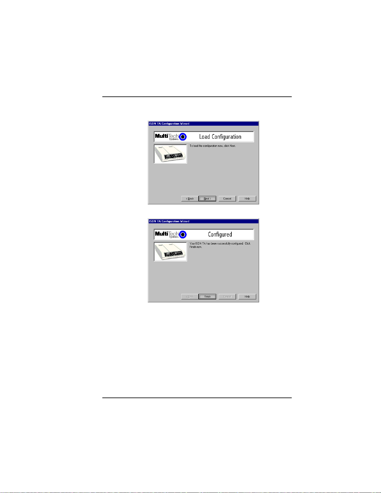
16. To load the configuration, click Next in the Load Configuration
dialog box.
17. Then click Finish in the Configured dialog box.
MultiModemISI Hybrid Series, ISIHP-2S/2U/4S/4U/4SD 57
Page 58
Software/Driver Installation
18. The first TA now is configured. Click Back to return to the
Configuration dialog box and repeat steps 4 through 9 to
configure the remaining TA(s). If you install multiple ISIHP cards
in the same PC, you must configure two TAs per 2S or 2U card
installed or four TAs per 4S or 4U card. For example, if you install
four ISIHP-2S/2U cards in one PC, you have to configure eight
TAs (two per card).
29. After all TAs are configured, close the ISDN TA Configuration
utility.
ConfigMenu Configuration Utility
The ConfigMenu configuration utility can be used as another means of
configuring the TA. ConfigMenu is installed in the TAs as part of the
firmware.
To use ConfigMenu:
1. Start a data communication program and select the COM port
where the TA is connected.
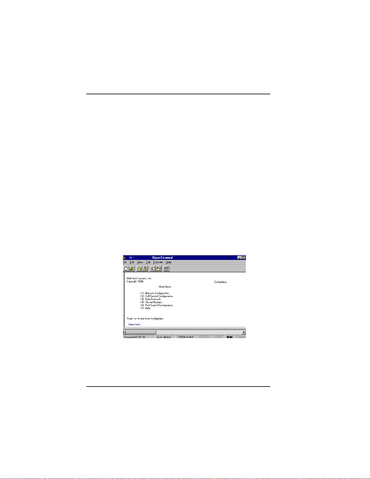
2. In the communication program dialog box, type AT@CONFIG
and press ENTER. ConfigMenus Main Menu appears (see screen
below).
3. To select menu item, type its number and press ENTER. A
submenu then appears where you can make selections. At the
lowest level, you can change a configuration option by selecting a
number or typing a value and pressing ENTER.
58 MultiModemISI Hybrid Series, ISIHP-2S/2U/4S/4U/4SD
Page 59

Software/Driver Installation
4. When you finish, close ConfigMenu by typing x and pressing
Enter.
5. You will be prompted to decide whether to save the configuration
when you exit the ConfigMenu program. Type y to have
ConfigMenu automatically save the configuration.
ConfigMenu Menus
Network Configuration Menuconfigures network parameters such
as switch type, data and voice TEIs, and data and voice MSNs. When
you finish, select Save Network Configuration to save your work.
Call Control Configuration Menuchanges how the TA originates
and answers calls. Options include Auto Answer, Rings to Answer,
Dialing Method, and Persistent DTR Dialing.
Data Protocol Menuchanges rate adaption protocol used by the TA.
Stored Numbers Menustores up to ten phone numbers ( maximum
of 20 characters each). Stored number 0 is the phone number that will
be dialed if persistent DTR dialing is enabled.
Port Control Configuration Menuconfigures TAs serial port,
including how TA responds to control signals on the serial interface.
Help Menuprovides assistance in navigating through the TA menu
system or viewing the ISIHPs firmware version numbers.
T erminal Adapter AT Commands
You can configure the terminal adapters using AT commands, just as
you would configure an analog modem. Use this method if you prefer
to work with AT commands or if you have a special requirement not
addressed by either of the configuration utilities.
To configure the TAs with AT commands:
1. Start a data communication program and select the first and third
COM ports to be configured.
2. Referring to records made for your system, enter AT commands in
the terminal window of the data communications program.
MultiModemISI Hybrid Series, ISIHP-2S/2U/4S/4U/4SD 59
Page 60

Software/Driver Installation
3. When you finish, use the &W command to save your new
configuration and to select it to load automatically when the ISIHP
is turned on.
4. Close the data communications program.
For more information, see the chapter on AT Commands and S-
Registers in this manual.
60 MultiModemISI Hybrid Series, ISIHP-2S/2U/4S/4U/4SD
Page 61

Software/Driver Installation
NetWare Connect (Novell) Driver Installation
{2S/2U models only}
Multi-Tech Systems provides AIO drivers for the ISIHP-2S/2U, so it
can function with Novell compatible asynchronous applications (e.g.,
NetWare Connect). The AIO driver is simply an NLM (NetWare
Loadable Module) that runs on the file server. Drivers must be loaded
on the file server where the board is installed. Drivers can be loaded
from the file servers console prompt or incorporated for autoloading
in the AUTOEXEC.NCF file.
To install the Multi-Tech AIO driver, copy the file AIOISIX.NLM to
the system directory of the file server from a workstation on the
network. To copy, you can use the following command:
COPY A:\NOVELL\AIOISIX.NLM F:\SYSTEM
To load the driver, go to the system or PC console (where the ISIHP2S/2U is installed) and enter the following at the prompt:
LOAD AIOISIX [port=W] [int=X] [name=Y] [note=Z]
To install the ISIHP scripts, copy aiomdms.mdc to
f:\system\aio\directory. Click Yes to overwrite the existing
aiomdms.mdc file.
Configuring Ports for NetWare Connect
To set up NetWare Connect ports, enter LOAD NWCCON at the
NetWare console prompt. LOAD NWCCON opens the NetWare
Connect Configuration Utility. Select the appropriate menu options
(modem type, speed, flow control, etc.)
Removing the Driver (Novell)
In Novell, remove file AIOISIX.NLM from the system directory and
make the appropriate changes to the Autoexec.ncf file.
MultiModemISI Hybrid Series, ISIHP-2S/2U/4S/4U/4SD 61
Page 62

Software/Driver Installation
SCO Open Server 5 Driver Installation
The installation utility provided by SCO is called custom. This section
describes opening the utility and installing the driver. The instructions
below should be used only on SCO Open Server 5 systems. When you
have completed the steps below, go to Multi-Tech Installation Script,
which immediately follows this section.
1. Insert the driver diskette into a floppy drive. If installing the driver
from your default floppy drive, type custom and press ENTER
to open the custom utility. If using a nondefault drive, you must
inform your system of the disk drive from where you are doing the
installation and specify the size and capacity of the diskette(s).
2. Select Software and press ENTER.
3. The main menu displays a list of options. Press ENTER to select
the highlighted item (default): Install.
4. Select From comsco and press ENTER. (Comsco is a sample
server name.)
5. Make sure the driver diskette is in the floppy diskette drive and
then press ENTER to select the highlighted item (default):
Floppy Disk Drive 0. The following message appears:
Examining media. Please wait
6. The system recognizes that you are installing the Multi-Tech Serial
Card Driver and prompts you to select the type of installation.
7. (A) In version 5.0.2, select Full Installation and press
ENTER to continue. The following messages appear:
Extracting Files...
Executing Multi-Tech Serial Card
Driver Init Script...
(B) In versions 5.0.4 and 5.0.5, press ENTER twice, or tab down to
install and press ENTER.
8. When installation finishes, this prompt appears:
Do you wish to continue ( y / n / q ):?
Type Y and press ENTER. A message appears and you can begin
configuring your system with the MultiTech Installation Script.
62 MultiModemISI Hybrid Series, ISIHP-2S/2U/4S/4U/4SD
Page 63

Software/Driver Installation
MultiTech Installation Script
The Multi-Tech Installation Script for SCO Open Server 5 systems
requests information about how many boards you want to install,
designations for communication ports and printer ports, and how many
pseudo devices you want to create for Multi_View utility. Based on
this information, the appropriate driver files will be installed and
linked with your systems kernel.
1. This text appears on the screen:
You can install up to 4 ISA/PCI cards in a
system. The PCI cards will be autodetected on
bootup. Enter the number of ISA cards you
want to install and configure on your system
(0-4):
Select 0, which indicates that your computer has a PCI bus and
can autodetect the ISI cards.
2. The following text appears on the screen:
Multi_View is a utility which will allow you
to have multiple sessions on terminals that
have multiple pages of physical memory. In
order for this utility to work with
MultiTechs serial cards, pseudo devices have
to be created in your /dev directory. These
devices are system-wide resources.
Enter the number of pseudo-devices to be
created for the use of Multi_View utility
(1 - 256).
The Multi_View utility initializes the multiple-page capability of
terminals with multiple pages of memory. The number specified
here is the total number of devices (between 1 and 256) available to
all Multi-Tech terminals and its the number of pseudo devices
available to the Multi_View utility.
Specify 8 pseudo devices for each ISIHP-2S or -2U card installed;
specify 16 for each ISIHP-4S or -4U card installed.
For example, if the computer contains three ISIHP-4S cards, you
would enter 48.
MultiModemISI Hybrid Series, ISIHP-2S/2U/4S/4U/4SD 63
Page 64

Software/Driver Installation
3. This text appears on the screen and relates to the /dev directory.
This script also creates the devices in your
system to communicate with the ports of
ISICOM. The default prefix for the tty ports
is ttyl. The default prefix for the printer
is prnl. Is this acceptable? (y/n/q).
For most users, its best to select y, which entails accepting the
default values. Then proceed to step 4.
Details for use of non-default port/printer values. The /dev
directory holds device-information files used by the kernel to
access the hardware. When you add an ISI card, you must give the
ISI ports unique names so they do not conflict with existing ports or
with other devices known to your system. If a device name has
already been assigned to an existing device and the operator assigns
that name to a new device, then the existing device will be deleted
when the ISI port using its name is created.
a. To use a non-default base name, type N and then enter a
basename having less than five characters. The base name you
select will be used for all ports on each card you install. ISI port
designations will have this form:
[basename prefix][board number][port letter].
basename: Length is one to four characters.
board number: Values will be 1, 2, 3, or 4, depending on
how many ISI cards are installed in your computer.
port letter: Use letters A through H.
In SCO UNIX, values A-H indicate modem ports.
Device basename selected: _________________
b. After you select a device basename, you are prompted for a printer
base name. This prefix identifies each port that supports a terminal
with a printer attached to its auxiliary port (for transparent
printing). Specify a unique printer base name (printer parameters
are outlined in the Multi_Setup Utility section in this manual ).
Printer base name selected: _________________
64 MultiModemISI Hybrid Series, ISIHP-2S/2U/4S/4U/4SD
Page 65

Software/Driver Installation
When you have specified the device base name and the printer base
name, press Enter to continue.
4. The confirmation screen lists the values you have selected. The
following text appears on the screen (default values are shown):
You have chosen the following setup
The tty prefix is ttyl.
The printer prefix is prnl.
Number of Multi_View pseudo devices
[user-specified number].
If these values are correct, type Y and the installation process will
continue. If there is an error in any of the values displayed, type N
and the first screen displays. Then re-enter the information for each
card.
When you accept the confirmation list (by typing Y), a series of
messages displays while the driver is being installed and the kernel
rebuilt. After the terminals have been added to the Terminal
Control database, and when the display says Press <Enter>
to continue:, then press ENTER. When Installation
complete displays, press ENTER again.
5. Select Host and press ENTER . Remove the diskette from the
drive.
6. Select Exit and press ENTER .
7. To reboot the system (required), enter the following commands:
Type shutdown -g0-y and press ENTER
OR
Type init 6 and press ENTER .
Driver installation for the ISIHP card now is complete.
Activating Ports in SCO Open Server 5
SCO Open Server 5 provides a device database that monitors the
activity of serial ports through which users can log onto the host. If
your ISI ports are used by terminals (e.g., to allow users to log onto
your host), you must create an entry in the systems device database
MultiModemISI Hybrid Series, ISIHP-2S/2U/4S/4U/4SD 65
Page 66

Software/Driver Installation
that furnishes specific information for the terminals that will be used
on each ISI port. The database is referenced each time a user attempts
to log in. If there is no database entry for a particular terminal, access
to the host is denied.
1. Turn on your system and verify that the firmware for each ISIHP
loads successfully. If the firmware for a given ISIHP card does not
load, none of its ports will be accessible. (If this happens, see
Multi-Techs Administrative Utility section in this manual.)
2. Type the complete name of the first device you want to create in
usr/lib/uucp/Devices. Substitute the specific base name,
board number, and port letter for the generic parameters in the
expression ttylbx. Use a lower-case x value for local DTE
(terminal) support and an upper case X value for modem control for
each port you want to enable. Example: ttyl2A denotes the
second ISI card (2) and the first port on that card (A). The port
status can be altered later, but one setting must be selected at this
time. The ACU line would read as follows:
ACU ttylbX - 9600 dialer name. Replace b, X and
dialer-name with appropriate values.
3. Repeat this process for each port on each board you have installed.
Record the setting you select for each port.
4. Using device names created in the previous section, type the
following command for each port you want to activate: enable
ttylbx
5. Repeat this command for each port you want to activate, using the
lower case letter for local terminal use or upper case for modem
control.
Note: Only one of the options (e.g., modem control or local
terminal access) should be enabled for any port at one time. For
example, you cannot enable ttyl1a and then enable ttyl1A. To
change the status of a port, disable the current status (disable
ttyl1a) and then enable it for the desired status (enable ttyl1A).
66 MultiModemISI Hybrid Series, ISIHP-2S/2U/4S/4U/4SD
Page 67

Software/Driver Installation
Removing the Driver (SCO Open Server 5)
To remove the Multi-Tech Serial Card Driver, enter the configuration
utility (e.g., custom for SCO Open Server 5) and follow instructions to
remove the entire driver and rebuild the kernel without the ISI driver.
If it is necessary to reinstall the driver due to I/O address or IRQ
overlap, remove the driver first.
Note: Remove the driver before permanently removing the ISI card from the
computer.
MultiModemISI Hybrid Series, ISIHP-2S/2U/4S/4U/4SD 67
Page 68

Software/Driver Installation
Linux Driver Installation
To install the Linux driver:
1. Insert the driver installation diskette.
2. Prepare a temporary installation directory: mkdir isicom
3. Change your current directory to the temporary installation
directory: cd \isicom
4. Place the file isicom.tar into the isicom directory.
5. Then extract the file using the tar utility: tar xvf /isicom/isicom.tar
6. Make sure the following are installed on your system: the make
utility, the GNU C compiler (gcc), and kernel sources.
7. Run the bash Install script to compile the driver as a loadable
module and to compile the user space firmware loader.
8. The files are copied to the destination folder. If you dont specify
the folder, the destination folder default is /usr/local/ISICOM
(case sensitive). This also creates device files for the ISI cards,
normal and callout ports, in the /dev folder.
9. To load the driver manually, use the ISIHP installation
configuration stored in the ISICOMStart file in the destination
folder.
Or, you can include the configuration in the appropriate start-up
script stored in the /etc/rc.d/ folder, so it loads when you start the
computer.
10. If you make any changes to this configuration, edit the first line of
the ISICOMSTART file. The correct syntax for this line is as
follows:
insmod <destination folder>isicom.o
ISIBase1=0xXXXX
Irq1=XX
ISIBase2=0xXXXX
Irq2=XX Linux Driver Installation
ISIBasex and Irqx represent the base I/O address and IRQ that are
passed to the driver at module loading time. See the insmod
manual page for more details on parameter passing.
68 MultiModemISI Hybrid Series, ISIHP-2S/2U/4S/4U/4SD
Page 69

Software/Driver Installation
Note: A base I/O address of 0, e.g., ISIBaseX=oxo, or omission of
these parameters for any card X, disables that particular card.
Miscellaneous:
Device files corresponding to ports on the ISIHP cards are created in the /
dev folder. Use ttyMxy for normal ports and cumxy for corresponding
callout ports. The letter x is the card number (14), and y is the port
number, (ap) for 16-port cards.
Normal ports (ttyM) are configured for dial-in connections. Callout
ports (cum) are used for dial-out connections.
To view busy I/O address space on your system, enter:
cat /proc/ioports
To view busy IRQs, enter:
cat /proc/interrupts
To load the driver manually, use insmod.
Example: To load two ISI cards configured with base I/O addresses
0x210 and 0x200 and IRQs 5 and 10, enter the following in the
destination folder:
insmod isicom
ISIBase1=0x210
Irq1=5
ISIBase2=0x200
Irq2=10
To remove the driver manually, enter rmmod isicom. This removes the
driver only if no ISI ports are in use.
MultiModemISI Hybrid Series, ISIHP-2S/2U/4S/4U/4SD 69
Page 70

Software/Driver Installation
70 MultiModemISI Hybrid Series, ISIHP-2S/2U/4S/4U/4SD
Page 71

Warranty and Service Information
Warranty & Service
Information
Upgrades and Support
You can access updated versions of firmware, drivers, flash utility
programs and other software-related support for ISIHP server cards
via the MultiTech web site and/or the MultiTech FTP site.
www.multitech.com (click Support; click Updates --Modem and ISI
Drivers; select operating system; then see Multiport Card PCI
Bus)
ftp://ftp.multitech.com (see Directory ISI Cards)
Service
Multi-Tech has an excellent technical support staff available to help
you get the most out of your Multi-Tech product. If you have any
questions about the operation of this product, call Technical Support
at (612) 717-5863. Model and serial numbers are located on the
Multi-Tech label on the component side of the ISIHP. To display the
firmware version, type ATI1 in terminal mode. Software versions are
printed on the diskette labels. Before calling Technical Support, note
the status of your equipment, including screen messages, diagnostic
test results, problems with a specific application, etc.
MultiModemISI Hybrid Series, ISIHP-2S/2U/4S/4U/4SD 71
Page 72

Warranty and Service Information
Limited Warranty
Multi-Tech Systems, Inc. (MTS) warrants that its products will be free from
defects in material or workmanship for a period of two years from the date
of purchase, or if proof of purchase is not provided, two years from date of
shipment. MTS MAKES NO OTHER WARRANTY, EXPRESSED OR
IMPLIED, AND ALL IMPLIED WARRANTIES OF
MERCHANTABILITY AND FITNESS FOR A PARTICULAR PURPOSE
ARE HEREBY DISCLAIMED. This warranty does not apply to any
products which have been damaged by lightning storms, water, or power
surges or which have been neglected, altered, abused, used for a purpose
other than the one for which they were manufactured, repaired by the
customer or any party without MTSs written authorization, or used in any
manner inconsistent with MTSs instructions.
MTSs entire obligation under this warranty shall be limited (at MTSs
option) to repair or replacement of any products which prove to be
defective within the warranty period, or, at MTSs option, issuance of a
refund of the purchase price. Defective products must be returned by
Customer to MTSs factory transportation prepaid.
MTS WILL NOT BE LIABLE FOR CONSEQUENTIAL DAMAGES
AND UNDER NO CIRCUMSTANCES WILL ITS LIABILITY EXCEED
THE PURCHASE PRICE FOR DEFECTIVE PRODUCTS.
72 MultiModemISI Hybrid Series, ISIHP-2S/2U/4S/4U/4SD
Page 73

A T Commands and S-Registers
AT Commands
and
S-Registers
Contents
Modem AT Commands ............................................................................... 74
Modem S-Registers .................................................................................... 94
Modem Result Codes ................................................................................ 101
Terminal Adapter AT Commands ..............................................................104
Terminal Adapter S-Registers ................................................................... 126
Terminal Adapter Result Codes ............................................................... 135
Using AT Commands to Operate the Terminal Adapter........................... 136
MultiModemISI Hybrid Series, ISIHP-2S/2U/4S/4U/4SD 73
Page 74

Modem AT Commands & S-Registers
Modem AT Commands
ISIHP modems are controlled by instructions called AT commands, so
called because the attention characters, AT, precede each command or
sequence of commands (known as a command string). You can send
commands to the modem from your keyboard while in terminal mode, or
you can use communications software to issue these commands
automatically.
The modem is in command mode when it is not dialing or online. When it is
in command mode, you have access to a complete communications system
that allows you to use several features, including the basic AT command set
described in this chapter. Using the basic AT command set, you can enter
phone numbers for automatic dialing, configure modem options, and
monitor telephone activity. In addition, you can command your modem to
perform advanced features such as error correction, data compression,
speed conversion, and more.
This chapter describes the modems operational modes and shows you how
to use each modem AT commands. These commands and responses are
compatible with all systems and with all data communications software
using the AT command set.
Modes of Operation
The modem operates in two basic functional modes: command mode and
online mode. (There is also an in-between state, wait-for-carrier, in which
the modem is out of command mode but not yet online.) When you turn on
the modem, it is in command mode and is ready to accept and respond to
commands from your keyboard or software.
The modem enters online mode after it dials, connects with another modem,
and detects a valid carrier signal. If it does not detect a carrier signal within
the time frame controlled by the S-register S7, the modem abandons the call
and reenters command mode.
You can make the modem enter online mode without dialing by entering AT
and then D (dial) or A (force answer mode). The modem exits online mode
if the carrier signal is lost or intentionally dropped. When this happens, the
modem hangs up and reenters command mode. By sending certain escape
characters to the modem while online, you can make it enter command
74 MultiModemISI Hybrid Series, ISIHP-2S/2U/4S/4U/4SD
Page 75

Modem AT Commands & S-Registers
mode without losing the carrier signal. While waiting to establish the
carrier, you can type any character from the keyboard to make the modem to
go back to the command mode.
Command Structure
You can control a wide variety of modem operations and options when the
modem is in command mode. AT commands tell the modem to dial a
number, to answer a call, to operate at a certain speed, to use a certain
compression technique, and many other functions. AT commands consist of
one or two letters, which may be preceded by an ampersand (&), a percent
character (%), or a slash character (/). The Q command, for example,
determines whether the modem returns result codes, while the &Q
command selects the asynchronous communications mode.
A parameter after a command (0, 1, 2, etc.) tells the modem which option to
use. If you do not specify a parameter, the modem assumes the 0 (zero)
option. E, for example, is the same as E0. You can issue several commands
on a single line (a command string) as long as the line does not exceed 40
characters.
Note: Each character in a command counts toward the 40 character
command line maximum. Example: Q1 is a single command, but it counts
as two characters in the command line.
Each command has a valid range of parameters. For example, &S can have
only 0 or 1 as a parameter. Valid commands always generate an OK result
code, and a few generate an additional response such as a list of parameters.
An invalid command such as &S3, which has a parameter outside the valid
range, generates an ERROR result code. Most commands have a default
parameter that is enabled when the modem is turned on or reset with the
ATZ or AT&F command. Factory defaults are stored in read-only memory
(ROM) and cannot be changed. User-defined defaults can be stored in
nonvolatile random-access memory (NVRAM) and can be changed or
deleted at will.
Command Editing
Always begin a command with the letters AT. Enter the entire command
string in upper or lower case, but do not mix cases within the command
MultiModemISI Hybrid Series, ISIHP-2S/2U/4S/4U/4SD 75
Page 76

Modem AT Commands & S-Registers
string. The AT command is not executed until you press ENTER. Use the
BACKSPACE key to erase the previous command character. It will not
erase the AT characters once they are typed. If your keyboard has no
BACKSPACE key, use CTRL+H. (You can change the character recognized
by the modem as BACKSPACE to any other ASCII character by changing
register S5.)
Press CTRL+X to cancel an entire command that has been typed but not yet
executed. This also clears the command buffer. The effect is the same as
backspacing the command, only quicker.
The modem stores characters entered in a command in its command buffer
until they are executed by pressing ENTER. The command buffers capacity
is 40 characters. The attention characters (AT) do not count toward the 40character command line maximum. You may use spaces for increased
readability when typing a command. Spaces are not stored in the command
buffer, and they do not count towards the 40-character command line
maximum. Special characters, such as hyphens and parentheses, are not
allowed.
If you exceed the 40-character limit or type invalid characters, the
command buffer is automatically erased and an ERROR message appears.
Retype the command within the 40-character limit, using only the allowed
characters.
The commands in this chapter are organized by function. Abbreviated
commands are listed on the next page by function along with a short
description and page numbers that refer to a more detailed description,
immediately following this list.
T opic Command Description
Dialing Action, p. 79 D Dial
H On-hook/off-hook
Dial Modifiers, p. 79 L, P, T, W Command accepted, but
has no function
, Command accepted, but
has no function
; Command accepted, but
has no function
76 MultiModemISI Hybrid Series, ISIHP-2S/2U/4S/4U/4SD
Page 77

Modem AT Commands & S-Registers
! $ @ ^ Command accepted, but
has no function
Phone Number Memory, p. 80 &Z Store a phone number
DS Dial a stored number
Configuration Storage & Recall, p. 81
&W Store configuration
&F Load factory default
configuration
Z Reset modem
&Y Select stored con-
figuration on power-up
Modem Responses (Result Codes), p. 82 E Echo command mode
characters
Q Result codes: enable/
disable
V Result codes: verbose/
terse
\V Protocol result code
X Result codes and call
progress
&Q Select asynchronous
communications mode
Online Connection, p. 84 B Answer tone
C Carrier control
F Echo online data
characters
&G Guard tones
-C Data calling tone
N Modulation handshake
\T Disable inactivity timer
Y Long space disconnect
MultiModemISI Hybrid Series, ISIHP-2S/2U/4S/4U/4SD 77
Page 78

Modem AT Commands & S-Registers
RS-232 Interface Controls, p. 86 &C Carrier Detect control
&D Data Terminal Ready
control
&S Data Set Ready control
Error Correction & Data \N0 or &Q6 Non-error correction
mode
Compression, p. 89 \N3 Auto-reliable mode
\N2 Reliable mode
%C0 Data compression
disabled
%C1 Data compression
enabled
Immediate Action, p. 89 A/ Repeat last command
I Information request
&B V.32 auto retrain
&V View current
configuration
Flow Control, p. 90 &M0 Asynchronous mode
&K0 or \Q0 Flow control disabled
&K3 or \Q3 Hardware flow control
&K4 or \Q1 XON/XOFF flow control
\X0 XON/XOFF no pass-
through
&J Auxiliary relay control
\J Enable data buffer
control
\G Modem port flow control
\K Set break control
Escape Sequences, p. 92 +++AT<cr> Default in-band escape
sequence
A Force answer mode
78 MultiModemISI Hybrid Series, ISIHP-2S/2U/4S/4U/4SD
Page 79

Modem AT Commands & S-Registers
O Go back online
Dialing Commands
Use dialing commands to dial and hang up.
Ds Dial
s = phone number
Default: none
Causes the modem to dial the telephone number immediately following it.
For example, if you type ATD5551212<cr>, the modem dials the number
555-1212.
Hn On-Hook/Off-Hook
n = 0 or 1
Default: 0
Makes the modem hang up (go on-hook) or simulate the action of picking
up a telephone handset (go off-hook).
H0 (or H) hangs up the modem
H1 brings the line off-hook, just as if you had picked up
the telephone handset.
It is not necessary to use the H1 command to bring the line off-hook when
using the D command. The modem automatically goes off-hook when you
press ENTER at the end of the dial command.
Dial Modifier Commands
ISIHP-2S/2U/4S/4U modems rely on the terminal adapters on the card for
dialing. For backwards compatibility, the following dial modifier commands
can be included in the dial string. They are accepted by the modem, but
ignore the actual function. These commands are:
L Redial Last Number
P, T Pulse or Tone Dialing
W Wait for New Dial Tone
, Dialing Pause
; Return to Command Mode After Dialing
MultiModemISI Hybrid Series, ISIHP-2S/2U/4S/4U/4SD 79
Page 80

Modem AT Commands & S-Registers
! Flash On-Hook
$ Detect Call Card Tone
@ Quiet Answer
^ Disable Data Calling Tone Transmission
Phone Number Memory Commands
ISIHP modems can store up to four telephone numbers in nonvolatile
memory. You can store the numbers with the &Z command and dial them
with the ATDS command.
&Zn=s Store a Phone Number
s = phone number
n= 0, 1, 2 or 3
Default: none
You can store a telephone number string in the modems phone number
memory. You can store four of these strings using the &Zn=s command.
The memory locations are labeled N0 through N3. For example, the
telephone number 1-612-555-1212 is stored at memory location N2 by
typing &Z2=16125551212 and pressing ENTER.
DSn Dial a Stored Number
n = 0, 1, 2, or 3
Default: none
You can automatically dial a telephone number that is stored in the modems
number memory by typing ATDSn, where n = 0 through 3. For example,
you can dial a number stored at N2 by typing ATDS2 in terminal mode and
pressing ENTER.
Configuration Storage and Recall Commands
The ISIHP-2S/2U stores parameters in two places. It stores factory default
parameters in read-only memory (ROM), and customized parameters in
nonvolatile random access memory (NVRAM). You cannot change the
default parameters in ROM, but you can change parameters in temporary
memory and then store them in NVRAM as custom settings. You can then
recall the custom settings as if they were factory default settings.
80 MultiModemISI Hybrid Series, ISIHP-2S/2U/4S/4U/4SD
Page 81

Modem AT Commands & S-Registers
&Wn Store Configuration
n = 0
Default: &W0
The &W command stores current AT commands and S-register values in
nonvolatile memory, so you wont lose your custom settings when you turn
off the modem or reset it.
&W0 (or &W) stores all current AT command and S-register values in
nonvolatile random access memory (NVRAM) and configures the modem
so it reads your custom settings in NVRAM when the modem is turned on
or when it is reset with the Z command. The &F reset command continues
to read the factory default settings in ROM.
&Fn Load Default Configuration
n = 0
Default: &F0
ISIHP-2S/2U modems store factory default AT command settings and Sregister values in read-only memory (ROM); they store your custom AT
command and S-register values in nonvolatile random access memory
(NVRAM).
The &F0 (or &F) command resets modem to the factory default values
stored in ROM.
Zn Reset Modem
n = 0 or 1
Default: none
The Z command resets the modem to the configuration last saved by the
&W command. The default values come from the customized configuration
in NVRAM.
Z1 is the same as Z0, and functions identically.
&Yn Select Stored Configuration for Hard Reset
n = 0
Default: 0
This command is included for compatibility with applications that issue the
&Y0 command. Modem functions are not changed.
MultiModemISI Hybrid Series, ISIHP-2S/2U/4S/4U/4SD 81
Page 82

Modem AT Commands & S-Registers
&Y0 selects the profile stored at location 0 on power-up.
Modem Response (Result Code) Commands
ISIHP modems can give responses to commands. The most common is OK,
but the modems also can alert you or your software to dial tones, busy
signals, connection speeds, and whether the connection is made with error
correction or compression enabled. These responses are called result codes;
they can be terse (numbers) or verbose (text).
En Echo Command Mode Characters
n = 0 or 1
Default: E1
Normally, when you type commands on the keyboard, the modem echoes
the characters back to the computer or terminal, which displays them on the
monitor. Use the E command to turn this feature off and on.
E0 disables the echo.
E1 enables the echo.
Qn Result Codes Enable/Disable
n = 0 or 1
Default: Q0
Use the Q command to enable or disable result codes for applications such
as computer-controlled auto dialing.
Q0 (or Q) enables result codes.
Q1 disables result codes for applications such as computer-controlled auto-
dialing.
Vn Result Codes (Verbose/Terse)
n = 0 or 1
Default: V1
The V command controls whether the modems result codes display as text
(verbose) or numeric (terse) messages. For example, if no carrier signal is
detected after dialing, the result can display either as NO CARRIER or as
the number 3.
82 MultiModemISI Hybrid Series, ISIHP-2S/2U/4S/4U/4SD
Page 83

Modem AT Commands & S-Registers
V0 (or V) displays the modems result codes as a number.
V1 displays result codes as text.
V2, an additional command given anytime after ATV1 is entered, displays
the connect message of both the local modem and the remote modem.
Xn Result Codes and Call Progress Selection
n = 0, 1, 2, 3, 4, 5, 6, or 7
Default: X4
Selects which result codes the modem provides in command mode and
determines whether the modem uses smart dialing or blind dialing. When it
smart dials, the modem listens for dial tones and busy signals and responds
to them. When it blind dials, the modem ignores the signals and relies on
timing instead.
X0 causes the modem to blind dial. Instead of looking for a dial tone, it
pauses for the time set in register S6 and then dials regardless. Once a
connection is made, it sends the basic code CONNECT to the terminal. It
ignores any busy signals.
X1 causes the modem to blind dial. In addition to the basic CONNECT
code, it provides extended codes consisting of the word CONNECT and the
speed of the connection (CONNECT 14400 or CONNECT 28800, for
example). In this mode, the modem does not recognize or respond to dial
tones or busy signals.
X2 causes the modem to wait for a dial tone before dialing. If it does not
detect a dial tone within the time set by S6, the modem sends a NO
DIALTONE result code to the terminal. In this mode, the modem provides
extended result codes but does not respond to busy signals.
X3 causes the modem to blind dial and to look for a busy signal. If it detects
one, it sends a BUSY result code to the terminal. In this mode, the modem
provides extended result codes, but it does not respond to dial tones.
X4 causes the modem to look for a dial tone and a busy signal and respond
with NO DIALTONE or BUSY, as appropriate. It also provides extended
result codes. It is the most useful setting for most data communication
programs and is the default setting.
X5 causes the modem to look for a dial tone and a busy signal and respond
MultiModemISI Hybrid Series, ISIHP-2S/2U/4S/4U/4SD 83
Page 84

Modem AT Commands & S-Registers
with NO DIALTONE or BUSY, as appropriate. It also provides extended
result codes. It is the most useful setting for most data communication
programs and is the default setting.
X6 causes the modem to look for a dial tone and a busy signal and respond
with NO DIALTONE or BUSY, as appropriate. It also provides extended
result codes. It is the most useful setting for most data communication
programs and is the default setting.
X7 causes the modem to wait for a dial tone before dialing. If it doesnt
detect a dial tone within the time set by S6, the modem sends only the basic
result code to the terminal (ERROR, NO CARRIER, or CONNECT, for
example). In this mode, the modem does not respond to busy signals.
&Qn Asynchronous Communications Mode
n = 0, 5, or 6
Default: &Q5
Allows you to select the type of asynchronous communications mode for
your modem.
Note: These commands are the same as several of the \Nn commands,
described later in this chapter.
&Q0 selects asynchronous mode with data buffering. This is the same as
\N0, nonerror correction mode with data buffering.
&Q5 selects error control with data buffering. This is the same as \N3,
V.42/MNP auto-reliable mode.
&Q6 selects asynchronous mode with data buffering. This is the same as
\N0, non-error correction mode with data buffering.
Online Connection Commands
The following commands control the conditions of the online connection.
Bn Answer Tone
n = 0, 1, 2, 3, 15, or 16
Default: B1 and B16
Selects the frequency the modem uses for its answer tone. (The answer tone
is the tone transmitted by the receiving modem to the calling modem, thus
84 MultiModemISI Hybrid Series, ISIHP-2S/2U/4S/4U/4SD
Page 85

Modem AT Commands & S-Registers
initiating the handshake between the two modems.) At higher speeds
(2400bps and above) there is no conflict because all protocols use the Bell
frequency of 2225Hz. Lower speeds require different frequencies.
B0 selects ITU-T V.22 mode when the modem is at 1200bps.
B1 selects Bell 212A when the modem is at 1200bps. This is a default.
B15 selects V.21 when the modem is at 300bps.
B16 selects Bell 103J when the modem is at 300bps. This is a default.
Cn Dummy Command
-Cn Data Calling Tone
n = 0 or 1
Default: -C0
The data calling tone is a tone of a certain frequency and cadence, as
specified in the V.25 standards, which identifies whether it is remote data,
fax, or voice. The frequency is 1300Hz, with a cadence of .5s on and 2s
off.
-C0 disables the V.25 data calling tone.
-C1 enables the V.25 data calling tone.
F Dummy command
&Gn Guard Tones
n = 0, 1, or 2
Default: &G0 (models outside U.K.) or &G2 (U.K.
models only)
Controls the presence or absence of guard tones from the transmitter when
in answer mode at either 1200 or 2400 bps. Guard tones are used in Europe
and other areas to allow the modem to function in the telephone systems.
Guard tones are not used in the United States. U.K. models are locked at
&G2 (1800 Hz guard tone).
&G0 disables ITU-T guard tones.
&G1 enables ITU-T 550 Hz guard tone.
&G2 enables ITU-T 1800 Hz guard tone.
MultiModemISI Hybrid Series, ISIHP-2S/2U/4S/4U/4SD 85
Page 86

Modem AT Commands & S-Registers
Nn Modulation Handshake
n = 0 or 1
Default: N1
Controls whether the local modem performs a negotiated handshake with
the remote modem at connection time when the communication speed of the
two modems is different.
N0 enables handshaking only at the communication standard specified by
S37 and the ATB command.
N1 always begins the handshake only at the communication standard
specified by S37 and the ATB command, but allows fallback to a lower
speed as the handshake proceeds. This is the default.
\Tn Inactivity Timer
n = 0
Default: \T0
The inactivity timer specifies the length of time, in minutes, that the modem
waits before disconnecting when no data is sent or received. This timer is
specified in register S30. The \T0 command disables the inactivity timer.
Yn Long Space Disconnect
n = 0, 1
Default: Y0
When two modems are connected in reliable mode, a link disconnect
request packet is sent to request a disconnect. In non-error correction mode,
there is no polite way to request a disconnect. As a result, some garbage
may be received when a hang-up command is issued.
Y0 disables the modems use of the break signal.
Y1 enables long space disconnect.
RS-232 Interface Commands
These commands define how the ISIHP-2S/2U modems use and respond to
standard
RS-232 signals.
&Cn Carrier Detect Control
n = 0 or 1
86 MultiModemISI Hybrid Series, ISIHP-2S/2U/4S/4U/4SD
Page 87

Modem AT Commands & S-Registers
Default: &C1
Allows you to control the Carrier Detect (CD) signal on the RS-232/V.24
interface. This is a signal from the modem to your computer indicating that
the carrier signal is being received from a remote modem. Normally, CD
goes high (turns on) when the modem detects a carrier on the
communications link and drops (turns off) when it loses the carrier. By
using &C, you can force the signal to stay high, or to drop momentarily
when the remote modem disconnects. This option is useful with some CBX
phone systems and mainframe front ends, which require CD to act in this
manner.)
&C0 ignores the state of the carrier from the remote modem. CD is forced
high.
&C1 allows CD to act normallyto go high when the modem detects a
carrier, and to drop when it loses the carrier.
&Dn Data Terminal Ready Control
n = 0, 1, 2, or 3
Default: &D2
The Data Terminal Ready (DTR) signal on pin 20 of the RS-232/V.24
interface must be high, or on, in order for the modem to operate. A high
DTR signal tells the modem that the computer it is connected to is ready to
communicate through the modem.
The DTR signal can also be used to cause the modem to reset to its default
parameters, as if you had given the modem an ATZ command.
&D0 (or &D) causes the modem to ignore the DTR signal and treat it as
always on.
&D1 causes the modem, if in online data mode, to enter command mode,
issue an OK and remain connected when the DTR drops.
&D2 causes the modem to hang up when DTR drops while the modem is in
online data mode.
&D3 causes the modem to reset when DTR drops . It will also hang up if it
is online.
MultiModemISI Hybrid Series, ISIHP-2S/2U/4S/4U/4SD 87
Page 88

Modem AT Commands & S-Registers
&Sn Data Set Ready Control
n = 0 or 1
Default: &S0
Controls the state of the Data Set Ready (DSR) signal on the RS-232/V.24
interface. Normally, DSR follows CD. You can force the signal high or
allow it to act normally.
&S0 forces DSR high (on).
&S1 allows DSR to act normally, that is, to follow CD.
Error Correction and Data Compression Commands
You can configure modems to any of three different V.42 modes of
operation (with or without compression): non-error correction, autoreliable, and reliable modes. You also can turn data compression on or off.
\Nn Error Correction Modes
n = 0, 1, 2, 3, 4, 5, or 7
Default: \N3
Select the modems error correction mode using the \N command.
\N0 disables the modems V.42 error correction capabilities, and the modem
functions as a non-error correction modem with data buffering. This is the
same as &Q6, described earlier in this chapter.
\N1 causes the modem to function in direct mode.
\N2 enables reliable mode, in which the modem uses its V.42 error
correction capabilities for all transmissions. In reliable mode, the modem
must be connected to a modem with the V.42 MNP protocol.
\N3 enables auto-reliable mode. During the handshaking procedures at the
start of the online connection, the modem queries whether the other modem
is using V.42 error correction. If the modem determines that the other
modem is using V.42, it switches itself into reliable (V.42) mode and
enables error correction. If it determines that the other modem is not using
V.42, the modem remains in non-error correction mode. (This is the same as
\N5 and \N7.)
\N4 enables reliable mode, in which the modem uses its V.42 error
correction capabilities for all transmissions. In reliable mode, the modem
88 MultiModemISI Hybrid Series, ISIHP-2S/2U/4S/4U/4SD
Page 89

Modem AT Commands & S-Registers
must be connected to a modem with a V.42 protocol (MNP or LAP-M).
The V.42 standard includes MNP Class 3 and 4 and LAP-M error correction
methods.
\N5 enables auto-reliable mode. During the handshaking procedures at the
start of the online connection, the modem queries whether the other modem
is using V.42 error correction. If the modem determines that the other
modem is using V.42, it switches itself into reliable (V.42) mode and
enables error correction. If it determines that the other modem is not using
V.42, the modem remains in non-error correction mode. (This is the same as
\N3 and \N7.)
\N7 enables auto-reliable mode. During the handshaking procedures at the
start of the online connection, the modem queries whether the other modem
is using V.42 error correction. If the modem determines that the other
modem is using V.42, it switches itself into reliable (V.42) mode and
enables error correction. If it determines that the other modem is not using
V.42, the modem remains in non-error correction mode. (This is the same as
\N3 and \N5.)
%Cn Data Compression
n = 0 or 1
Default: %C1
The %C command allows you to disable data compression. Data
compression is normally enabled.
%C0 disables V.42bis/MNP 5 data compression.
%C1 enables V.42bis/MNP 5 data compression.
Immediate Action Commands
Use immediate action commands to obtain information about AT commands
and current modem settings.
A/ Repeat Last Command
Default: None
Type A/ to repeat the previous command. Do not precede this command
with AT or press ENTER to execute it.
In Information Request
MultiModemISI Hybrid Series, ISIHP-2S/2U/4S/4U/4SD 89
Page 90

Modem AT Commands & S-Registers
n = 0
Default: none
This command displays specific product information about your modem.
I0 or I returns the controller firmware version number. Use this command to
identify your modems firmware level before calling Multi-Tech Technical
Support. (Same as I3.)
&Bn Dummy command
&V View Current Configuration
Default: none
Use the &V command to display the active modem settings.
Flow Control Commands
Flow control refers to techniques used by data terminal equipment and the
modem to pause and resume the flow of information between them. It
prevents a device from accepting more data than it can handle. The modem
implements flow control in both directions. When the modem halts the flow
of data, it is called flow control. When the computer halts the flow, it is
called pacing.
&Kn Local Flow Control Selection
n = 0, 3, or 4
Default: &K3
Allows you disable flow control and enable hardware or software flow
control.
&K0 completely disables data flow control initiated by the modem. (Same
as \Q0.)
&K3 enables modems use of Clear to Send (CTS) signal on the RS-232/
V.24 interface to regulate data flow. When CTS drops, data flow is
suspended until the signal goes high (on) again. This method of flow control
works in conjunction with pacing (i.e., computer-initiated flow control),
which uses the Request to Send (RTS) signal on the RS-232/V.24 interface.
Hardware flow control cannot be enabled unless an active error correction
protocol is selected. This is the factory default setting. (This is the same as
\Q3.)
90 MultiModemISI Hybrid Series, ISIHP-2S/2U/4S/4U/4SD
Page 91

Modem AT Commands & S-Registers
&K4 enables XON/XOFF software flow control. XON/XOFF flow control
is an in-band method of data flow regulation. In-band data regulation means
that the XON (^Q) and XOFF (^S) characters are inserted into the stream of
data rather than using separate control lines. When an XOFF character is
detected, the data stream is suspended until an XON character is detected. If
you issue the &K4 command to the modem, it will respond to XON/XOFF
pacing, and use XON/XOFF characters as its own method of flow control to
the computer. (This is the same as \Q1.)
The drawback to using this method of pacing is that some files may contain
these characters as part of the file data. If such a file is transferred using a
modem with XON/XOFF flow control enabled, the file transfer could fail
due to indefinite suspension.
\Qn Local Flow Control Selection
n = 0, 1, or 3
Default: \Q3
Allows you disable flow control and enable hardware or software flow
control.
\Q0 completely disables data flow control initiated by the modem. (This is
the same as &K0.)
\Q1 enables XON/XOFF software flow control. XON/XOFF flow control is
an in-band method of data flow regulation. In-band data regulation means
that the XON (^Q) and XOFF (^S) characters are inserted into the stream of
data rather than using separate control lines. When an XOFF character is
detected, the data stream is suspended until an XON character is detected. If
you issue the &K4 command to the modem, it will respond to XON/XOFF
pacing, and use XON/XOFF characters as its own method of flow control to
the computer. (This is the same as &K4.)
The drawback to using this method of pacing is that some files may contain
these characters as part of the file data. If such a file is transferred using a
modem with XON/XOFF flow control enabled, the file transfer could fail
due to indefinite suspension.
\Q3 enables modems use of Clear to Send (CTS) signal on the RS-232/
V.24 interface to regulate data flow. When CTS drops, data flow is
suspended until the signal goes high (on) again. This method of flow control
works in conjunction with pacing (i.e., computer-initiated flow control),
MultiModemISI Hybrid Series, ISIHP-2S/2U/4S/4U/4SD 91
Page 92

Modem AT Commands & S-Registers
which uses the Request to Send (RTS) signal on the RS-232/V.24 interface.
Hardware flow control cannot be enabled unless an active error correction
protocol is selected. This is the factory default setting. (This is the same as
&K3.)
\Xn XON/XOFF Pass-Through
n = 0, 1
Default: \X0
When XON/XOFF pacing is active, the local modem has two options
regarding the XON and XOFF characters. It can respond to and discard the
characters from the computer, or it can respond to the characters and pass
them through the data communications link to the remote modem, thereby
pacing the remote modem as well.
\X0 causes the modem to respond to and discard the XON and XOFF
characters (default)
\X1 causes the modem to respond to and pass on the XON and XOFF
characters
\Jn Data Buffer Control
n = 0
Default: \J0
\J0 disables force line rate less than or equal to DTE rate
\J1 enables force line rate less than or equal to DTE rate
\Kn Set Break Control
n = 0, 1, 2, 3, 4, 5
Default: \K5
Determines how the modem processes a break signal received from the
local DTE during an online connection.
\K5 causes the modem to send the break to the remote modem in sequence
with transmitted data, non-destructive, non-expedited.
Escape Sequences
Escape sequences are also known as escape codes. They are used to cause
92 MultiModemISI Hybrid Series, ISIHP-2S/2U/4S/4U/4SD
Page 93

Modem AT Commands & S-Registers
the modem to enter command mode from online mode without
disconnecting the call.
+++AT<cr> In-Band Escape Sequence
If the modem is online with a remote modem, you can cause the modem to
enter command mode without disconnecting the call by typing an escape
code. The default escape code used by the modem is three plus signs (+++)
followed by the letters AT, up to 10 command characters (most typically H,
to hang up), and ENTER. The modem then escapes to command mode,
executes the command (if any), and remains in command mode. For
example, to hang up the modem at the end of a call, type +++ATH <cr>.
A Force Answer Mode
You can use the A command to force the modem into answer mode. Type
ATA when in command mode to immediately bring your modem off-hook,
out of command mode, into online answer mode, and to cause it to transmit
its carrier signal over the phone line. If no responding carrier tone is
received by your modem within 45 seconds (or by the time you specified in
register S7), your modem stops transmitting its tone, hangs up, and goes
back into command mode.
On Go Back Online
n = 0, 1, or 3
Default: none
Use the O command to bring the modem out of command mode and back
into online mode. The O command reverses the result of entering the escape
code. The O command brings modem into the online mode (originate or
answer) it was in prior to entering command mode.
O0 causes the modem to exit command mode and return to online data
mode.
O1 causes the modem to issue a retrain before returning to online data
mode.
O3 causes the modem to issue a rate renegotiation before returning to
online data mode.
MultiModemISI Hybrid Series, ISIHP-2S/2U/4S/4U/4SD 93
Page 94

Modem AT Commands & S-Registers
Modem S-Registers
S-registers are small regions of memory where modem configuration
information is stored. Whereas AT commands tell a modem what to do, S-
registers tell the modem how to do it. Each S-register has a name that
consists of the letter S and a number (S0, S1, S2, etc.), hence the term S-
register. Use the Sr? command to read the value stored in an S-register and
the Sr=n command to change it.
S0 Number of Rings Until Modem Answers
Unit: 1 ring
Range: 0255
Default: 0
Defines number of rings the modem waits before answering an incoming
call. Default value is zero, which effectively disables the auto-answer
function. When auto-answer is disabled, the modem can only answer via the
ATA command. Set the S0 register value to one to cause the modem to
answer the call immediately after the first ring. Maximum number of rings
that can be configured is 255.
S1 Ring Count
Unit: 1 ring
Range: 0255
Default: 0
Counts number of rings that have occurred. It is a read type of register and
is seldom used in typical operation. Each time an incoming ring signal is
detected, S1 increases its value by one, up to a maximum of 255. If you set
S1 to a value other than its default value of zero, or if the value is increasing
with rings, this new value remains stored in S1 for eight seconds after the
last ring is counted, after which the value reverts back to zero.
S2 Escape Code Character
Unit: Decimal
Range: 0255
Default: 43 (+)
Defines escape code character by its decimal ASCII code. Default character
is the plus (+) sign (decimal 43). S2 can be set for any ASCII character.
94 MultiModemISI Hybrid Series, ISIHP-2S/2U/4S/4U/4SD
Page 95

Modem AT Commands & S-Registers
Setting an S2 value greater than 127 results in no escape character, resulting
in no means of entering command mode from online mode without breaking
the online connection unless you use the BREAK method.
Note: If you change the S2 value, you must make corresponding changes in
your data communications software.
S3 Return Character
Unit: Decimal
Range: 0127
Default: 13 (^M)
Defines carriage return character by its decimal ASCII code. Default setting
is the ^M character (decimal 13), the code for ENTER on most keyboards.
Can be set for any ASCII character.
Note: If you change the S3 value, you must make corresponding changes in
your data communications software.
S4 Line Feed Character
Unit: Decimal
Range: 0127
Default: 10 (^J)
Defines the line feed character by its decimal ASCII code. Default setting is
^J (decimal 10), the code for the line feed key on most keyboards that have
such a key. Can be set for any ASCII character.
S5 Backspace Character
Unit: Decimal
Range: 0127
Default: 8 (^H)
Defines backspace character by its decimal ASCII code. Default setting is
the ^H character (decimal 8), the code for BACKSPACE on most
keyboards. Can be set for any ASCII character. Setting S2 to a value greater
than 32 disables the backspace character.
Note: If you change the S5 value, you must make corresponding changes in
your data communications software.
MultiModemISI Hybrid Series, ISIHP-2S/2U/4S/4U/4SD 95
Page 96

Modem AT Commands & S-Registers
S6 Wait Time for Dial Tone
Unit: 1 second
Range: 265 (North America), 4255 (International), 47
(U.K.)
Default: 2 (North America), 4 (International and U.K.)
Defines length of time the modem waits after ENTER is pressed before
carrying out a dial command. Default setting is two seconds for North
America, four seconds elsewhere.
S7 Time to Wait for Carrier
Unit: 1 second
Range: 1255 (USA), 145 (Canada and International),
or 155 (UK)
Default: 50 (North America and International) or 55
(U.K.)
Determines amount of time the modem waits for a carrier signal before it
disconnects. Default value is 50 seconds except the UK model, which
defaults to 55 seconds. After dialing, the modem waits for a carrier signal
for up to 50 or 55 seconds and if none is detected, terminates the call.
Maximum S7 value is 255 seconds for the US model, 45 seconds for
Canadian and International models, and 55 seconds for the UK model. S7
also determines the wait for silence time for the @ dial modifier.
S8 Pause Time for Comma
Unit: 1 second
Range: 065 (North America), 4255 (International), 47
(UK)
Default: 2 (North America), 4 (International and UK)
Determines the length of pause caused by a comma character in a dialing
command. Default setting is two seconds for North American model and
four seconds for international and UK models. S8 can be set for up to 65
seconds. S8 also defines the length of time the modem waits before retrying
a call after it detects a busy signal. Some computer systems need more than
two seconds to reset. If this is the case, increase the value of S8.
96 MultiModemISI Hybrid Series, ISIHP-2S/2U/4S/4U/4SD
Page 97

Modem AT Commands & S-Registers
S10 Carrier Loss Disconnect Delay Time
Unit: 100 ms
Range: 1254
Default: 20
Defines the length of time, in milliseconds, that the modem waits after a
loss of carrier signal before the it disconnects. The default setting is 2000
ms (20 units of 100 ms each). Maximum delay is 25400 milliseconds, or
25.4 seconds (decimal 254).
S11 Tone Dialing Spacing and Duration
Unit: 1 ms
Range: 50 - 150 (US) or 80255 (Canada, UK,
International)
Default: 95 (US) or 80 (Canada, UK, International)
Sets the speed of tone dialing (spacing and tone duration times). The default
value is 95 units for domestic models and 80 units for Canadian and
International models, where each unit is one ms. In other words, for
domestic modems, each tone is sustained for 95 ms followed by a 95 ms
pause. The minimum S11 value allowed is 50 ms (50 units). The maximum
S11 value is 150 ms (150 units).
S28 Enable / Disable V.34 Modulation
Unit: decimal
Range: 0, 1255
Default:1 (enabled)
Enables or disables V.34 modulation. Setting S28 to zero (0) disables V.34
modulation. Any other setting (1-255) enables V.34 modulation.
S35 Data Calling Tone
Unit: decimal
Range: 01
Default: 0 (disabled)
Enables or disables the V.25 data calling tone, which allows remote data,
fax and voice discrimination. Setting S35 to zero (0) disables V.25 data
calling tone; setting S35 to 1 enables data calling tone. The default setting is
1.
MultiModemISI Hybrid Series, ISIHP-2S/2U/4S/4U/4SD 97
Page 98

Modem AT Commands & S-Registers
S37 Maximum Dial Line Rate
Unit: decimal
Range: 019
Default: 0
Sets the maximum dial line rate. When set to zero (0), the maximum dial line
rate is the same as the maximum modem speed. This is the most common
setting and allows other modem functions to actually determine the line rate
used for each connection. It is the default. Consider using S37 to set a
maximum dial line rate if you need to artificially retain a lower modem speed.
0 = maximum modem speed 13 = 19200 bps
1 = reserved 14= 21600 bps
2 = 1200/75 bps 15 = 2400 bps
3 = 300 bps 16 = 26400 bps
4 = reserved 17 = 28800 bps
5 = 1200 bps 18 = 31200 bps
6 = 2400 bps 19 = 33600 bps
7 = 4800 bps
8 = 7200 bps
9 = 9600 bps
10 = 12000 bps
11 = 14400 bps
12 = 16800 bps
S42 Enable / Disable Auto Rate
Unit: decimal
Range: 0-1
Default: 1 (enabled)
Enables and disables the 56K auto rate. Retrain and fallback are disabled in
data mode. Set S42 to zero (0) to disable auto rate, or 1 (the default) to
enable auto rate.
S43 Enable / Disable V.32bis Start-up Auto Mode
Unit: decimal
98 MultiModemISI Hybrid Series, ISIHP-2S/2U/4S/4U/4SD
Page 99

Modem AT Commands & S-Registers
Range: 0-1
Default: 1 (enabled)
Used for testing and debugging only. Enables and disables V.32bis start-up
auto mode operation. Set S43 to zero (0) to disable start-up auto mode, or 1
(the default) to enable start-up auto mode.
S89 Off-line Time
Unit: 1 second
Range: 0, 5-255
Default: 0
Sets the length of time, in seconds, a modem waits in the off-line command
mode before it goes into standby mode. If S89 is set to 20 seconds, the
modem waits 20 seconds in off-line command mode before going into
standby mode. Setting S89 to zero (0) prevents the modem from ever
entering standby mode.
Setting S89 to any value between zero and five (1-4) effectively sets the
value to five, because five seconds is the minimum possible wait time.
S108 Line Code Control
Unit: Decimal
Range: 0, 1
Default: 1
Controls the line coding used by the modem.
S108 = 0 mu-law
S108 = 1 A-law (default)
S109 PCM Mode Control
Unit: Decimal
Range: 02
Default: 1
Controls the PCM ( pulse code modulation) mode (V.90 or K56Flex).
Determines which mode the modem will answer in for PCM connections.
S109 = 0 K56Flex support only
S109 = 1 Both V.90 and K56Flex supported
S109 = 2 V.90 support only
MultiModemISI Hybrid Series, ISIHP-2S/2U/4S/4U/4SD 99
Page 100

Modem AT Commands & S-Registers
Reading and Assigning S-Register Values
Use the S command to assign a value to an S-register and to read an its
current value. To read an S-register value, in terminal mode, type S, the Sregister number, and a question mark (?), and press ENTER. For example,
to display the value of register S7, type ATS7? and press ENTER. The
value appears as a three-digit decimal number (e.g., 045).
To assign a new value to an S-register, type S, the S-register number, an
equals sign (=), and a decimal number. Convert all ASCII characters to their
decimal equivalents before entering. Valid S-register decimal values are
shown for each register in the previous section. To make the change
permanent, use the &W0 command.
Examples of Assigning V alues
1. You want to have longer pauses caused by the comma in a dial
command: five seconds instead of two. Type ATS8=5 to assign 5 as
the value for register S8. The modem now pauses five seconds for
every comma in a dial command.
2. You want to configure your modem to answer incoming calls after
the fourth ring instead of after the first ring. To configure register
S0 with a value of 4, type ATS0=4 and press ENTER.
3. You are calling long distance to another country code, and it is
taking a long time to connect. The register S7 (time to wait for
carrier) factory default setting of 50 seconds is insufficient; a timeout occurs and cancels the call before a connection is made. To
change the S7 value to 75 seconds, type ATS7=75 and press
ENTER . Now, after dialing, the modem allows 25 more seconds
for a carrier signal before aborting the call. The additional 25
seconds should provide enough time for international calls.
Examples of Reading Values
1. To verify that you entered the value correctly in the preceding
examples, type ATS8? and press ENTER in the first example,
ATS0? in the second example, and ATS2? in the third example.
You should receive the responses 005, 004, and 075, respectively.
2. When configuring S-registers, it is a good practice to include the
100 MultiModemISI Hybrid Series, ISIHP-2S/2U/4S/4U/4SD
 Loading...