

Page 1

ISI5634PCI/4/8
User Guide
Page 2

User Guide
Model ISI5634PCI/4/8
P/N S0000109, Revision D
This publication may not be reproduced, in whole or in part, without prior
expressed written permission from Multi-Tech Systems, Inc. All rights reserved.
Copyright © 2001 by Multi-Tech Systems, Inc.
Multi-Tech Systems, Inc. makes no representation or warranties with respect to the
contents hereof and specifically disclaims any implied warranties of merchantability
or fitness for any particular purpose. Furthermore, Multi-Tech Systems, Inc.
reserves the right to revise this publication and to make changes from time to time in
the content hereof without obligation of Multi-Tech Systems, Inc. to notify any
person or organization of such revisions or changes.
Record of Revisions
Revision Description
A Manual released. All pages at Revision A.
(2/12/99)
B Novell Netware installation instructions added.
(4/9/99)
C Updated for universal ISI drivers
(8/21/00)
D Updated info on MTS patents, Windows 2000, Windows
(6/1/01) Me, and Novell Netware, and regulatory matters.
TRADEMARKS
The Multi-Tech logo is a registered trademark of Multi-Tech Systems, Inc.
Windows NT, Windows 95, and Windows 98 are registered trademarks of Microsoft.
Pentium is a registered trademark of Intel Corporation.
ofnItcatnoCofnItnetaP
.cnI,smetsyShceT-itluM
.rDeladooW5022
.A.S.U,21155
0053-587)367(
7179-823)008(
:troppuShceT
9342-279)008(
atosenniM,weiVsdnuoM
4789-587)367(:xaF.S.U
moc.hcetitlum.www:tenretnI
gnidnePstnetaP
gniwollofehtfoeromroenoybderevocsiecivedsihT
;497,509,5;280,900,6;311,210,6;768,130,6:stnetap
;435,218,5;305,518,5;765,518,5;065,468,5
;726,467,5;826,467,5;235,097,5;860,908,5
;862,376,5;653,427,5;052,493D;985,457,5
;805,916,5;030,826,5;495,446,5;752,376,5
;140,775,5;685,295,5;946,006,5;324,716,5
;844,645,5;397,955,5;222,473D;527,475,5
;074,174,5;958,005,5;402,535,5;593,645,5
;524,054,5;982,254,5;689,354,5;616,364,5
;895,353D;356,553D;856,553D;467,163D
rehtO.472,103,5;265,903,5;563,553,5;441,353D
Page 3

Contents
Chapter 1—Introduction and Description ...........................5
Introduction ............................................................................................ 6
How to Use This Manual........................................................................ 8
ISI5634PCI Applications ......................................................................... 8
What Is in Your Modem Package?.......................................................... 9
Technical Specifications ....................................................................... 10
Chapter 2—Hardware Installation ......................................11
Introduction .......................................................................................... 12
Safety Warnings Telecom ..................................................................... 12
Hardware Installation Procedures ......................................................... 12
Install ISI5634PCI card WITHOUT auxiliary module: 12
Install ISI5634PCI card WITH auxiliary module: ........ 14
Chapter 3 — Software/Driver Installation .......................... 17
Introduction .......................................................................................... 18
Installing ISI5634PCI Software for Windows 2000 ................................ 18
ISI5634PCI for Win 2000: Install Modems to COM Ports ..................... 26
Remove ISI5634PCI Driver (Windows 2000) ......................................... 31
ISI5634PCI for Win 2000: Installing ISI Management Software ............ 32
Installing the ISI5634PCI Card in Windows NT 3.51/4.0 ....................... 33
Installing Modems to COM Ports in Windows NT............................... 37
Removing ISI5634PCI Driver in Windows NT 3.51/4.0.......................... 42
ISI5634PCI Software Installation Procedure for Windows 95/98/Me .... 42
Installing Modems to COM Ports in Win 95 /98/Me............................. 47
Removing the ISI5634PCI Driver (Windows 95/98/Me) ........................ 51
NetWare Driver Installation .................................................................. 51
Configuring Ports for NetWare Connect ........................ 52
Removing the Driver (Novell) .......................................... 52
SCO Open Server 5 Driver Installation.................................................. 52
Install from CD-ROM: ...................................................... 53
Install driver from floppy disk ......................................... 54
MultiTech Installation Script ........................................... 55
Page 4

Linux Driver for ISI5634PCI-4/8............................................................. 60
LINUX: Pre-Installation Issues ........................................ 60
LINUX: Copy driver from the media ............................... 61
LINUX: Driver installation and loading ......................... 62
LINUX: Set baud rate ....................................................... 63
LINUX: Verify ports .......................................................... 63
LINUX -- Dial-in configuration: ..................................... 65
LINUX -- PPP setup:......................................................... 65
Removing the ISI Driver (Linux) ..................................... 66
RedHat Linux 6.2/7.0 RPM Drivers for
ISI5634PCI-4/8 Server Cards ................................................................. 67
LINUX-RPM: Pre-Installation Issues .............................. 67
LINUX-RPM: Copying the driver from the media .......... 67
LINUX-RPM: Verifying the ports..................................... 70
LINUX-RPM -- Dial-in configuration: ............................ 71
LINUX-RPM -- PPP setup: ............................................... 71
Removing the ISI Driver (Linux-RPM) ............................ 72
Chapter 4—
Chapter 5—
Software User License Agreement ...................................................... 102
Limited Warranty ................................................................................ 104
AT Commands, S-Registers, & Result Codes ........ 75
Warranty, Service, and Tech Support .................. 101
On-Line Warranty Registration ..................................... 104
Tech Support ...................................................................................... 105
Service ................................................................................................ 106
Appendix A—Regulatory Information ..................................... 108
Index .................................................................................... 116
Page 5

Chapter 1—Introduction and Description
Page 6

ISI5634PCI/4/8 User Guide
Introduction
Welcome to the world of data communications. You have acquired one
of the finest intelligent data and fax modems available today from one
of Americas oldest and most respected modem manufacturersMultiTech Systems, Inc.
The new IntelligentSerialInterface card, model ISI5634PCI is a
multiport serial port expansion card with four V.90/K56flex modems.
The cards capability can be doubled by adding an auxiliary module,
which also contains four modems. It is an excellent hardware solution
for adding fast serial ports to communication servers and async hosts
that have 32-bit PCI bus architecture.
Serial ports are essential to
Communication servers that pool modems and other
communication devices for users on a LAN
Asynchronous hosts that provide user access through serial
ports.
The ISI5634PCI ships with drivers for the following multiuser operating
systems: Windows® 2000, Windows NT, versions 3.51 and 4.0;
Windows 95 , Windows 98, and Windows Me; Novell Netware
versions 3.x and 4.x.; SCO Open Server 5; and Linux.
The IntelligentSerialInterface card can be combined to support
asynchronous serial devices (local or dial-up). The ports can be used
to connect basic terminals with or without multiple pages of memory to
multiplexer channels and asynchronous modems. Each ISI5634PCI port
can support as many screens as there are physical pages of memory on
the terminal. In Windows 95/98/Me, a built-in autodetect utility enables
detection of Multi-Tech modems and sets the proper initialization
strings.
ISI5634PCI Modems
The ISI5634PCI modems incorporate V.90/K56flex technology, which
enables Internet connections at data rates up to 53 Kbps over standard
telephone lines. V.90/K56flex technology is able to send data
downstream from the Internet to your computer at these speeds
because data on the telephone network typically is converted from
6
Page 7

Chapter 1—Introduction and Description
digital to analog only once before it reaches your modem. Upstream
transmissions and transmissions between client modems are limited to
data rates of 33.6 Kbps, as are downstream transmissions that are
converted more than once on the telephone network.
Note: Though these modems are capable of 56 Kbps download
performance, line impairments, public telephone infrastructure, and
other external technological factors currently prevent maximum
56 Kbps connections.
Modems on the ISI5634PCI card are Plug and Play capable with
interactive automatic dialing and command mode configuration. In
standard mode, you can store up to four command lines or telephone
numbers of up to 40 characters each in the modems nonvolatile
memory. In callback security mode, you can store up to 30 passwords
and dialing strings. The modems pulse- or tone-dial and recognize dial
tones and busy signals for reliable call-progress detection. The
modems can detect AT&T calling card tones. They also have DTR
dialing, Caller ID, remote configuration, callback security, two-wire
leased-line, and 11-bit capabilities, and incorporate self-resetting
lightning protection. Serial port speeds can be set to 230,400 bps. They
are both FCC registered for connection without notification to the
telephone company.
The ISI5634PCI card has full-duplex intelligent modems with V.42 error
correction, V.42bis data compression, and V.17 (14,400 bps), Class 1
and 2, Group 3 fax capabilities. Voice functionality (+V commands) has
also been added to the features of ISI5634PCI modems.
Intelligent
The ISI5634PCI is a multiport serial port expansion card that adds data
buffering on each port for enhanced serial port performance. The
ISI5634PCI features an on-board microprocessor to coordinate the
communications activity of your local and remote terminals. Using the
ISI5634PCI to provide additional serial connections enables your
systems processor to perform more efficiently since the ISI5634PCI
handles all byte-by-byte interrupts generated by asynchronous
terminals and stores the data in buffers.
Serial
Interface
7
Page 8

ISI5634PCI/4/8 User Guide
The processor, along with 256K bytes of RAM, works to allocate
resources dynamically to the most active port. The ISI then generates
one interrupt for an entire block of information and transfers the block
to the systems microprocessor.
The ISI5634PCI has eight Mini RJ-11 jacks. It is a 3/4 size add-on card
that supports a high-speed interface up to 230 Kbps.
How to Use This Manual
This manual contains hardware and operating system driver installation
procedures, technical support and warranty information, and an
appendix for additional information. Hardware configuration and
installation procedures are described in Chapter 2. Installing the
ISI5634PCI card also involves linking a driver to the operating system.
This information is provided in Chapter 3.
It is assumed you have basic PC skills. Therefore, we have not
included step-by-step instructions for basic operations such as
logging in and file editing, etc.
Most of the steps listed in the driver installation section instruct you
to press Enter. This is a reference to the key commonly known as the
Enter, carriage-return, or Return key. Also, please note the difference
between the letter O and the number 0. Both the letter and the number
may be used in this manual.
ISI5634PCI Applications
The ISI5634PCI is an ideal solution for adding ports when a powerful
microcomputer used as a server or host lacks enough connectivity to
accommodate the desired number of users. The ISI5634PCI provides
eight additional serial ports with every card installed, with a potential
of four additional cards installed per systemfor a total of thirty-two
serial ports per system.
8
Page 9

Chapter 1—Introduction and Description
What Is in Your Modem Package?
Your modem package has several components. Make sure you have
them all before trying to operate your modem. Your package should
include:
One ISI5634PCI/4 card
One ISI5634PCI/EC auxiliary module (or extender card; part of
the ISI5634PCI/8 model only)
Four modular telephone cables (Eight with the ISI5634PCI/8 model)
Quick Start Guide (printed manual)
A full User Guide on CD-ROM
An installation CD-ROM that includes drivers, auxiliary software,
and documentation (readme files, this User Guide, etc.)
If any of these items are missing, contact Multi-Tech Systems or your
dealer/distributor (see the Warranty, Service, and Tech Support section
for information on contacting Multi-Tech via telephone and the
Internet).
Related Manuals
The following related manuals are available on request:
82076200 MT56XX Fax Class 1 Developers Guide
82006501 TR29.2 (Proposed) Class 2 Fax Command Reference
Manual
88301900 MT5634ZBA/ZBA-V User Guide (online manual)
S0000099 Voice +V Commands Developers Guide
9
Page 10

ISI5634PCI/4/8 User Guide
Technical Specifications
Computer Requirements
Pentium®- based PC or compatible with PCI Bus Architecture
One of these operating systems: Microsoft Windows 2000, NT v.
3.51 or v. 4.0; Windows 95, Windows 98 and Windows Me;
Novell Netware versions 3.x and 4.x., SCO Open Server 5; Linux.
A CD-ROM drive.
100K bytes of hard disk space
Physical/Electrical/Environmental
Dimensions: 6.875" x 4.2"
17.46 cm x 10.67 cm
Baud Rates: 300 bps to 230 Kbps per port
Bus Type: PCI
Connectors: Four (or eight) RJ-11 mini jacks
Cables: Four (or eight) modulated telephone cables
Temperature: 32° to 120°F (0° to 50°C)
Power: 2.5 amp @ +5v DC (8 ports; ISI5634PCI/8)
1.7 amp @ +5v DC (4 ports; ISI5634PCI/4)
Base I/O Address: One 16-byte address space per card
Interrupt Request (IRQ): One IRQ per card (can be shared)
Warranty: Two years
Manufactured in Mounds View, MN, U.S.A.
10
Page 11

Chapter 2—Hardware Installation
Page 12

ISI5634PCI/4/8 User Guide
Introduction
Included in this chapter are two sets of instructions for installing the
Multi-Tech ISI5634PCI card in your PCI bus personal computer. The
first set of instructions is for installing the ISI5634PCI card. The second
set contain instructions for installing the ISI5634PCI card and the
auxiliary module.
Safety Warnings Telecom
1. Never install telephone wiring during a lightning storm.
2. Never install telephone jacks in wet locations unless the jacks are
specifically designed for wet locations.
3. This product is to be used with UL and CUL listed computers.
4. Never touch uninsulated telephone wires or terminals unless the
telephone line has been disconnected at the network interface.
5. Use caution when installing or modifying telephone lines.
6. Avoid using a telephone (other than a cordless type) during an
electrical storm. There may be a remote risk of electrical shock from
lightning.
7. Do not use the telephone to report a gas leak in the vicinity of that
leak.
8. To reduce the risk of fire, use only No. 26 AWG or larger
Telecommunication line Cord.
Hardware Installation Procedures
Installing the ISI5634PCI card
module:
1. Before handling the ISI5634PCI, discharge any static in your body
by touching a piece of grounded metal such as the computer
chassis.
2. Carefully remove the ISI5634PCI from its antistatic bag, handling it
only by the mounting bracket and edges. Do not touch the goldplated connectors along the bottom edge. (You may want to save
packaging for possible future use.)
3. Visually inspect the ISI5634PCI card. If you have any concerns
about its condition, call Technical Support at 800-972-2439.
12
WITHOUT
the auxiliary
Page 13

Chapter 2—Hardware Installation
4. To avoid damaging the ISI5634PCI card and your PC, make sure
your computer and any peripheral equipment connected to it are
turned off. The ISI5634PCI can be installed in any Pentium
equivalent PCI bus computer.
5. Remove the cover of your computer as instructed in your
computers documentation.
6. Locate the unused PCI slot you will be using for your ISI5634PCI
card and remove the slot cover according to instructions in your
computers documentation.
7. Install the ISI5634PCI card into the selected expansion slot in the
same manner as any other add-on card, as instructed in your
computers documentation.
8. Fasten the retaining bracket to computer chassis and replace
cover.
9. Plug one end of the phone cable into each modems LINE jack and
the other end into a phone line wall jack.
There are 8 phone line receptacles on the ISI5634PCI-4, as well as
8 phone line receptacles on the ISI5634PCI-8. However, only four
of these receptacles are functional on the ISI5634PCI-4 card.
When connecting phone lines to the ISI5634PCI-4, be sure to use
the first four receptacles on ISI5634PCI-4 card, starting at the edge
of the board with the screw-hole for attaching the card to the
computer chassis.
Note: The LINE jack is not interchangeable with the wall jack.
Do not plug the phone into the LINE jack or the line cable into
the wall jack.
Note: The Federal Communications Commission (FCC) and
Industry Canada impose certain restrictions on equipment
connected to public telephone systems. See Appendix A
Regulatory Information for more information.
10. Turn on the power to the computer. You now are ready to install
the software/drivers.
13
Page 14

ISI5634PCI/4/8 User Guide
Installing the ISI5634PCI card
1. The auxiliary module attaches to the ISI5634PCI card. If you
already have this card installed, you must remove it from the PC to
install the auxiliary module.
2. Before handling the ISI5634PCI card or the auxiliary module,
discharge any static in your body by touching a piece of grounded
metal such as the computer chassis.
3. Carefully remove the ISI5634PCI card and module from the
antistatic bag, handling only by the mounting bracket and edges.
Do not touch the gold-plated connectors along the bottom edge.
(You may want to save packaging for possible future use.)
4. Visually inspect the ISI5634PCI card and the auxiliary module. If
you have any concerns about its condition, call Technical Support
at (800) 972-2439.
5. To avoid damaging the card, module, or your PC, make sure your
computer and any peripheral equipment connected to it are turned
off. The ISI5634PCI and auxiliary module can be installed in any
Pentium equivalent PCI bus computer.
6. Remove the cover of your computer as instructed in your
computers documentation.
WITH
the auxiliary module:
14
Page 15
Chapter 2—Hardware Installation
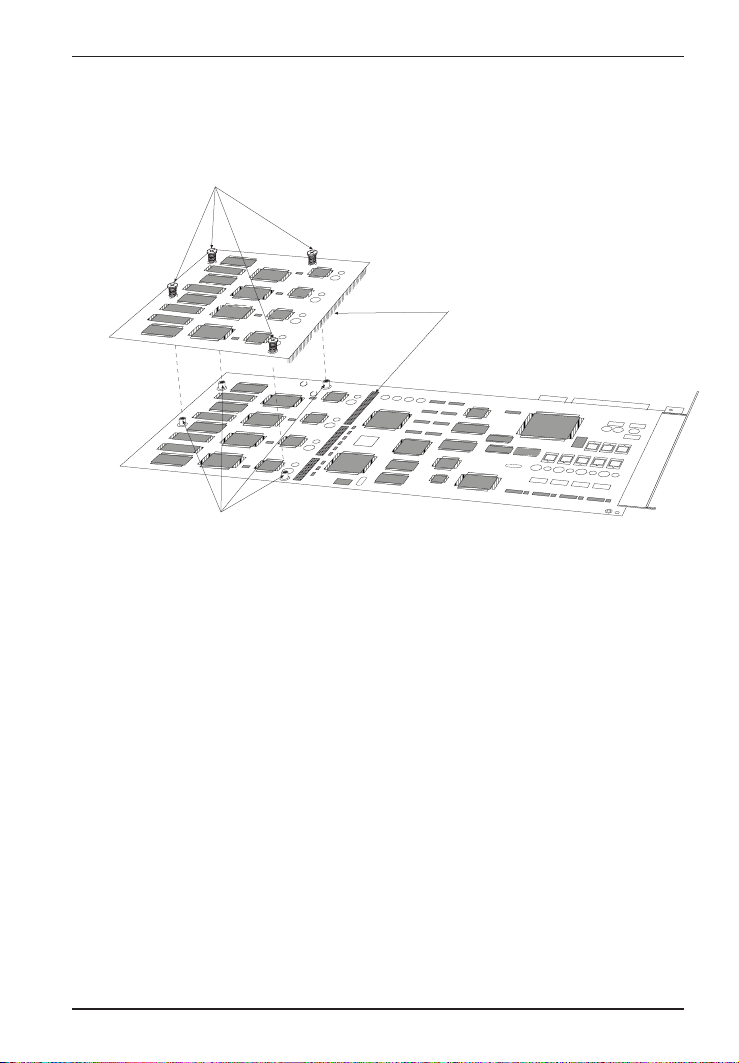
7. Before installing the ISI5634PCI card, carefully line up the pin-out
connectors of the ISI5634PCI card with the pin-out connectors of
the auxiliary module. See figure below.
Mounting screws
Pin-out
connectors
Mounting posts
8. Press gently but firmly to seat the module onto the card.
9. Fasten the mounting connections (four screws) of the auxiliary
module to the ISI5634PCI card. See figure above.
10. Install the ISI5634PCI card into the selected expansion slot in the
same manner as any other add-on card, as instructed in your
computers documentation.
15
Page 16

ISI5634PCI/4/8 User Guide
11. Fasten the retaining bracket to computer chassis and replace
cover.
12. Plug one end of the phone cable into each modems LINE jack and
the other end into a phone line wall jack.
13. Turn on the power to the computer. You now are ready to install
the software/drivers.
Note: The LINE jack is not interchangeable with the wall jack.
Do not plug the phone into the LINE jack or the line cable into
the wall jack.
Note: The Federal Communications Commission (FCC) and
Industry Canada impose certain restrictions on equipment
connected to public telephone systems. See Appendix A
Regulatory Information for more information.
16
Page 17

Chapter 3 — Software/Driver Installation
Page 18

ISI5634PCI/4/8 User Guide
Introduction
The ISI5634PCI card ships with drivers for each of the following
operating systems: Windows® 2000, Windows NT, Windows 95,
Windows 98, Windows Me, Novell Netware versions 3.x and 4.x, SCO
Open Server 5, and Linux. This chapter describes the installation of
these drivers.
In most cases, you will receive the ISI software drivers on a CD-ROM.
In certain situations, however, software may be downloaded from the
MultiTech web site, often onto diskette, and then installed. The
instructions in this chapter generally presume that the driver files are
being installed from CD-ROM and therefore show driver files being
loaded from locations on the ISI CD-ROM. If installation is from
diskette, you will be loading driver files from file path locations on that
diskette. For example, a driver file found at
E:\servcard\drivers\win2000\ when installing from CDROM, might be located simply at A:\ if installation is from diskette.
Installing a device driver modifies your system. For this reason, only
the super user (system administrator) is allowed to perform the
installation. If you cannot login as administrator, find the person in
your organization with this authorization (i.e., password). To begin
driver installation, login as administrator. Then proceed with the
appropriate section: Windows 2000, Windows NT or Windows 95/98/
Me. For Novell Netware, you need rights to read and write to the
SYSTEM directory. The Unix-based OSs SCO and Linux similarly
require such administrative rights.
Installing ISI5634PCI Software for Windows 2000
NOTE: A series of installation wizard screens will appear
repeatedly during this procedure (step 12). This is not an error.
Do not discontinue the procedure when the installation wizard
screens repeatedly appear.
1. Shut down Windows 2000 and turn off the PC.
2. Install the ISI5634PCI card in an available PCI expansion slot in
the computer. Follow the computer manufacturer's instructions
concerning installation of expansion cards. Observe standard
precautions regarding electro-static discharge (ESD) when
18
Page 19
Chapter 3—Software/Driver Installation
handling the ISI5634PCI board (the board should be kept in its
shipping bag until used). During installation, handle the
ISI5634PCI circuit card by its edges and keep one hand in contact
with the PC chassis.
3. Turn on the PC and start Windows 2000.
4. Insert the ISI driver CD-ROM into the CD-ROM drive (if drivers
have been downloaded from the MultiTech web site, they will
typically be on diskette; in that case, insert diskette into floppy
drive).
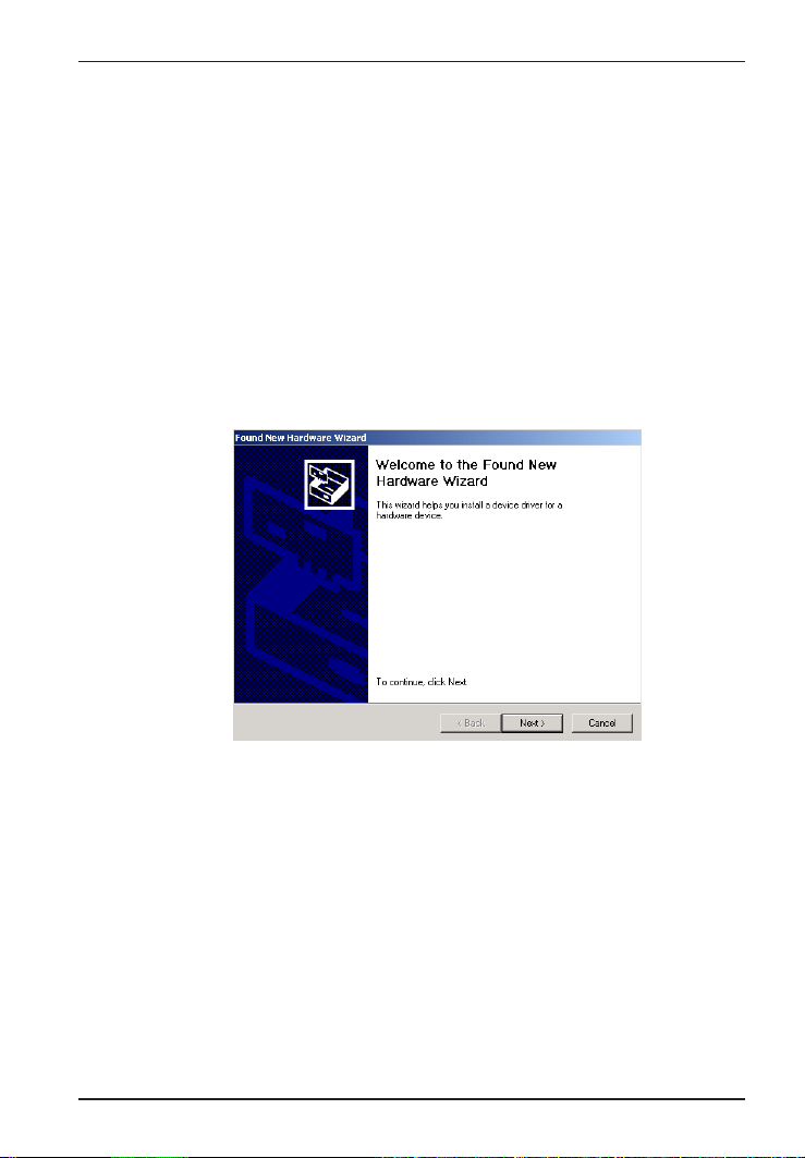
5. Windows 2000 will detect the ISI5634PCI card. The Found New
Hardware Wizard- Welcome screen will appear.
Click Next.
19
Page 20
ISI5634PCI/4/8 User Guide
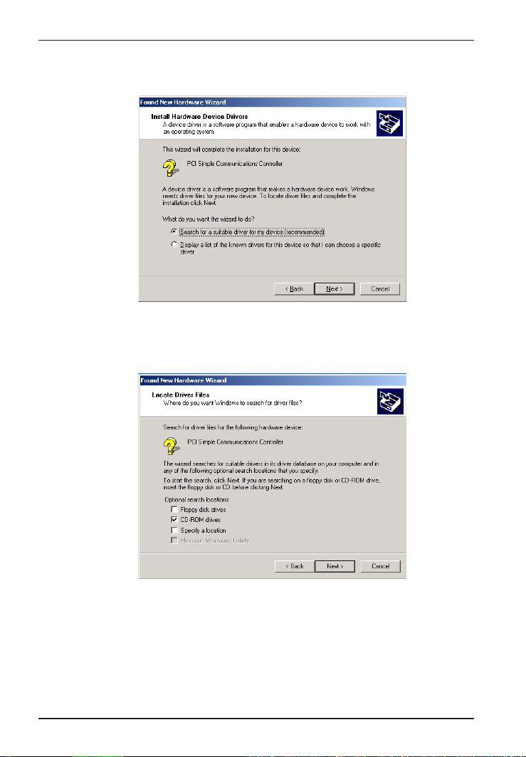
6. The Install Hardware Device Drivers screen appears. Select
"Search for a suitable driver ..." and click Next.
7. The Locate Driver Files screen appears (Windows 2000 is seeking
the driver for the ISI5634PCI card). Select CD-ROM drives and
click Next.
20
Page 21
Chapter 3—Software/Driver Installation
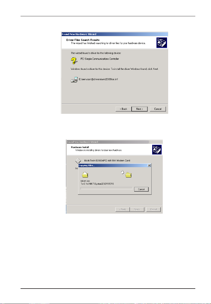
8. The Driver File Search Results screen appears.
Click Next.
9. A progress screen will appear briefly while files are being copied.
21
Page 22
ISI5634PCI/4/8 User Guide
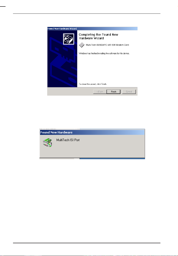
10. A completion screen will appear.
Click Finish.
11. Immediately after the ISI driver installation has been completed,
another Found New Hardware screen will appear briefly indicating
that the MultiTech ISI Port has been detected.
22
Page 23
Chapter 3—Software/Driver Installation
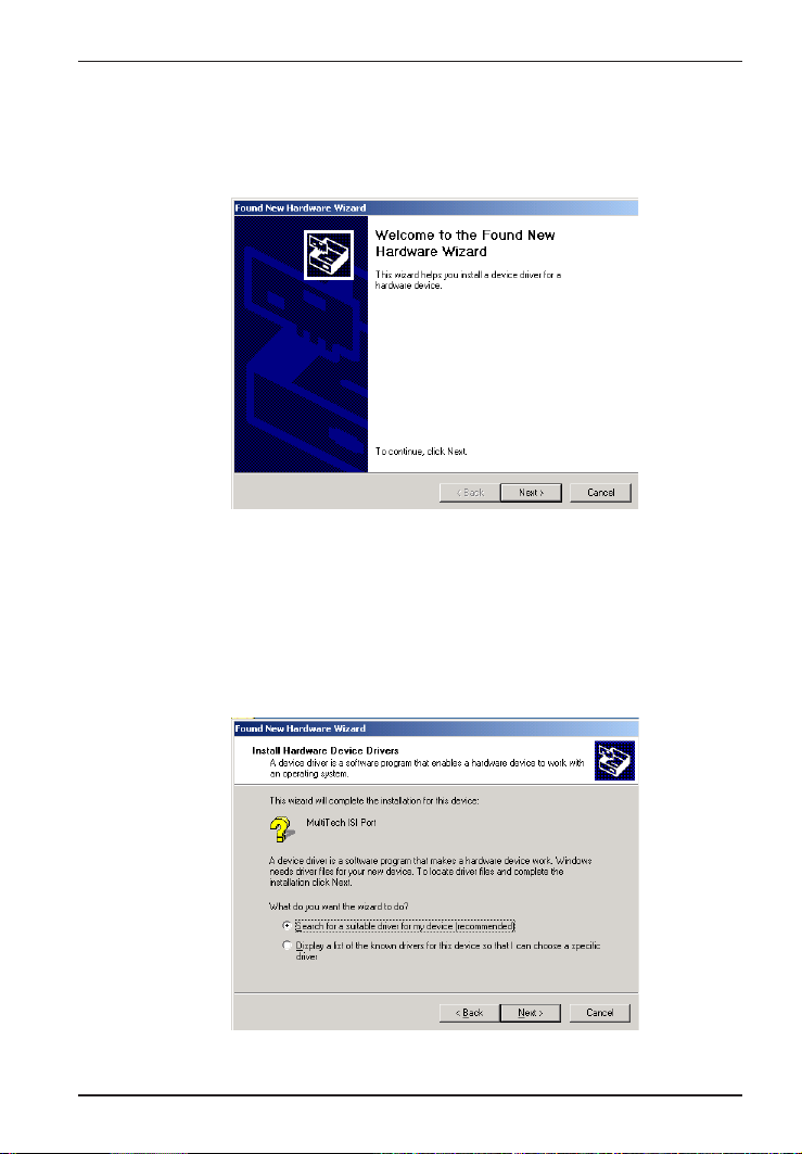
A second sequence of installation wizard screens appears. This
sequence of screens deals with the setting up of ISI ports. The
first screen in this sequence is the Found New Hardware Wizard --
Welcome screen.
The Found New Hardware -- MultiTech ISI Port screen will appear
once for each modem on the ISI5634PCI card:
8 times for the ISI5634PCI-8; or,
4 times for the ISI5634PCI-4.
12. The Install Hardware Device Drivers screen appears.
Select Search for a suitable driver ... and click Next.
23
Page 24
ISI5634PCI/4/8 User Guide
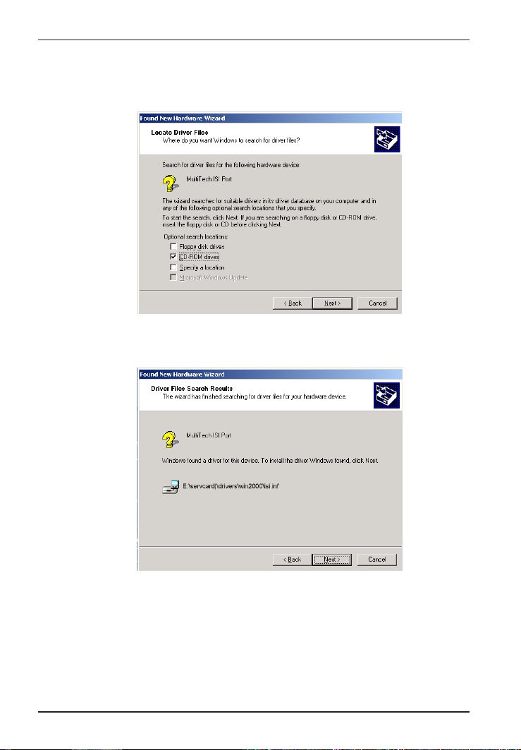
13. The Locate Driver Files screen appears (Windows 2000 is
seeking the ISI Port device driver). Select CD-ROM drives and
click Next.
14. The Driver Files Search Results screen will indicate that the
isiport.inf file has been found on the CD-ROM.
24
Click Next.
Page 25
Chapter 3—Software/Driver Installation
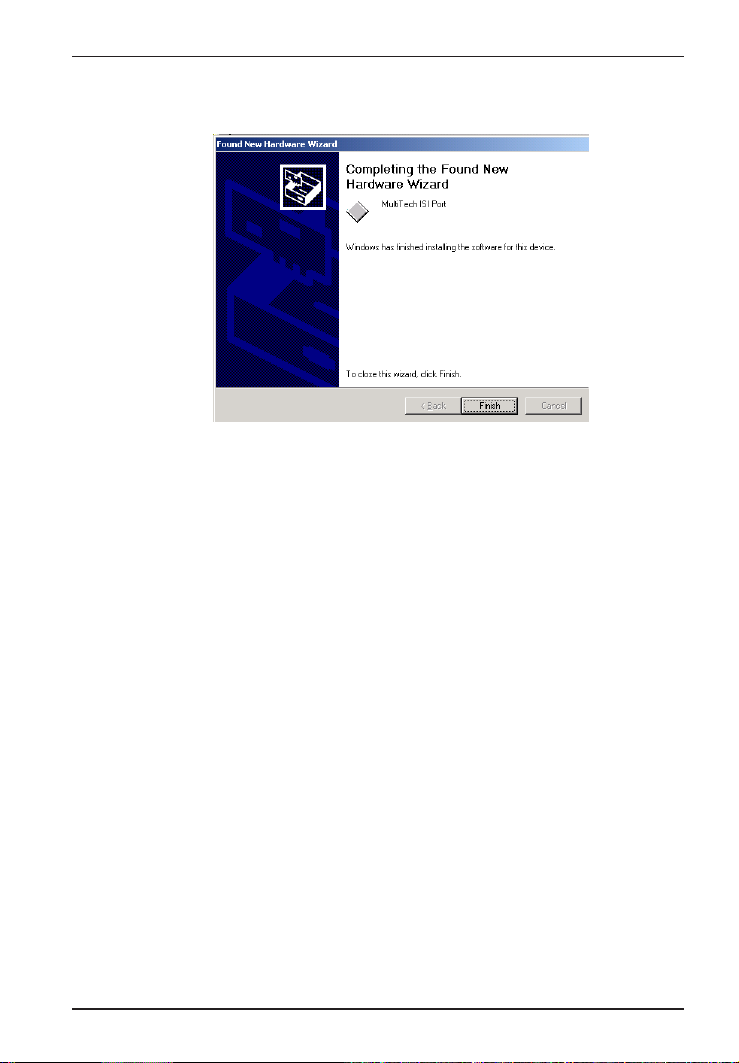
15. A completion screen will appear. It will indicate that the first
MultiTech ISI Port has been set up successfully.
Click Finish.
Notice that the auto-detection facility of Windows 2000 will repeat
the ISI Port installation sequence 3 more times for ISI5634PCI-4,
or 7 more times for ISI5634PCI-8. That is, the Found New Hardware
-- MultiTech ISI Port screen will appear many times after the ISI
driver has been located. On this screen, the messages Found
New Hardware and Installing ... will appear alternately.
Please understand that the repetition of these screen sequences is
normal and is not an error. It does not indicate any problem with
your PC, or with the MultiTech ISI card, or its driver software.
16. Driver installation for the ISI5634PCI card is complete.
25
Page 26

ISI5634PCI/4/8 User Guide
ISI5634PCI for Windows 2000: Installing Modems to
COM Ports
Pre-Requisite: Installation of Windows 2000 driver software must be
completed before you can install the modems of the ISI5634PCI
card.
1. Go to Start | Settings | Control Panel | Phone and Modem Options.
2. The Location Information screen appears.
Enter the appropriate area code and access number. Click OK.
3. At the Phone and Modem Options screen, click on the Modems tab
and click Add.
26
Page 27
Chapter 3—Software/Driver Installation
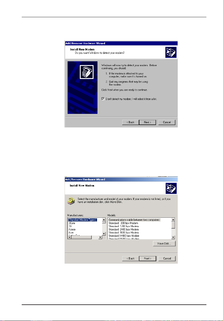
4. At the Install New Modem screen, click on "Don't detect my
modem ... " and click Next.
5. If the software driver CD-ROM (or other media, in cases of using
drivers downloaded from the MultiTech web site) is not already in
the appropriate disk drive in the PC, insert it now.
6. The Add/Remove Hardware Wizard screen will appear.
Click Have Disk ... .
27
Page 28
ISI5634PCI/4/8 User Guide
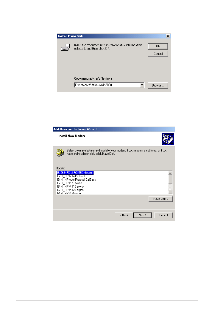
7. The Install from Disk screen will appear.
Type or browse for the file path of the modem software (for
example, E:\servcard\drivers\win2000). Click OK.
8. The Install New Modem screen will appear.
28
Highlight ISI5634PCI -8 PCI 56K Modem. Click Next.
Page 29
Chapter 3—Software/Driver Installation
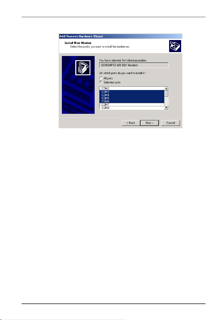
9. The Install New Modem - port list screen will appear.
Highlight the COM ports on which you want modems to be installed.
You must allocate 4 ports for the ISI5634PCI-4, or 8 ports for the
ISI5634PCI-8.
Click Next.
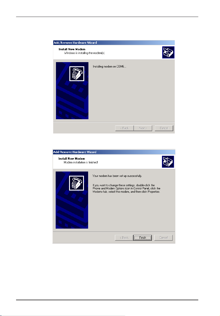
10. A progress screen will appear as modem installation begins.
29
Page 30
ISI5634PCI/4/8 User Guide
11. Screens denoting the installation of modems to specific COM
ports will appear for each modem installed.
12. A completion screen will appear.
30
Click Finish.
Page 31

Chapter 3—Software/Driver Installation
13. The Phone and Modems Options screen (Modems tab) will re-
appear and display the modems that have just been assigned to
COM ports.
Installation of modems to COM ports in Windows 2000 is now
complete.
Remove ISI5634PCI Driver (Windows 2000)
1. Go to Start | Settings | Control Panel.
2. Click on Add/Remove Hardware. Click Next.
3. Click on Uninstall/Unplug a device and click Next.
4. In the subsequent screen, click on Uninstall a device and click
Next.
5. At the Add/Remove Hardware Wizard screen, highlight the ISI
driver file for the specific server card that you intend to remove.
Click Next.
6. When you are asked to confirm removal, click on the Yes radio
button and click Next.
7. Click Finish. You can remove the driver for only one ISI5634PCI
card at a time.
31
Page 32

ISI5634PCI/4/8 User Guide
ISI5634PCI for Windows 2000: Installing ISI Manage-
ment Software (server OSs only)
If you are using a Windows 2000 Server operating system ("Server" or
"Advanced Server"), you must decide whether you want to use the
MultiTech ISI Management Software in conjunction with your
ISI5634PCI board. The ISI Management Software is shipped with the
ISI card and, alternatively, can be downloaded from the MultiTech web
site (www.multitech.com).
1. Turn on your computer and start Windows 2000.
2. Insert the CD-ROM or diskette containing the ISI Management
Software into your CD-ROM or floppy drive.
3. Go to Start | Run. In the Run window, enter the file path at which
the ISI Management Software setup program is located; for
example D:\MANAGEMENT\SETUP.EXE.
Click OK.
4. The ISI Management setup screen appears. At the Welcome
screen, click Next.
5. A progress screen appears while files are copied. If the Error
Creating Virtual WWW Server message appears, it may indicate
that there was an attempt to install the ISI Management Software
on a client version of Windows 2000. (The ISI Management
Software can be installed only in the Windows 2000 Server and
Windows 2000 Advanced Server operating systems.)
6. A completion screen appears. Select "Yes, I want to restart my
computer now" and click Finish.
After the computer has restarted, the installation of the ISI
Management Software will be complete.
32
Page 33

Chapter 3—Software/Driver Installation
Installing the ISI5634PCI Card in Windows NT 3.51/4.0
The following procedure describes how to install the ISI5634PCI in a
system operating Microsoft Windows NT 3.51 or 4.0 for use with
Remote Access Service (RAS) server and other communications/fax
server type applications. These procedures apply to both 3.51 and 4.0.
1. Turn off the PC.
2. Install the ISI5634PCI card in an available PCI expansion slot in
the computer. Follow the computer manufacturer's instructions
concerning installation of expansion cards. Observe standard
precautions regarding electro-static discharge (ESD) when
handling the ISI5634PCI board (the board should be kept in its
shipping bag until used). During installation, handle the
ISI5634PCI circuit card by its edges and keep one hand in contact
with the PC chassis.
3. Turn on the PC and start Windows NT.
4. Insert the ISI driver CD-ROM into the CD-ROM drive (if drivers
have been downloaded from the MultiTech web site, they will
typically be on diskette; in that case, insert diskette into floppy
drive).
33
Page 34

ISI5634PCI/4/8 User Guide
5. Click Start, Settings, Control Panel, and then double-click
Network. In the Network dialog box, click the Adapters tab.
Click Add.
6. The Select Network Adapter dialog box appears. Click Have Disk.
34
Page 35

Chapter 3—Software/Driver Installation
7. The Insert Disk dialog box appears. Type in or browse for the
path (file directory location) of the Windows NT driver (for
example, E:\servcard\drivers\winnt\setup.exe). C l ick OK.
8. The Select OEM Option dialog box appears. Click OK. The driver
files will be copied from the installation CD-ROM.
A transient dialog box will appear indicating the progress of the
setup program.
9. The ISI Cards dialog box appears. Click Add.
10. Then the ISI Card Settings dialog box appears. In the Port Count
field, enter the correct port count, as follows:
allocate 4 ports for the ISI5634PCI-4
allocate 8 ports for the ISI5634PCI-8
Select the first port number (Starting Port field) for ISI5634PCI
modems. Typically, in a newly outfitted server, this will be COM3.
In the Bus Type field, select PCI.
When the correct settings have been made, click Done.
35
Page 36

ISI5634PCI/4/8 User Guide
11. The ISI Cards dialog box appears again showing the port resource
allocation that has just been made.
To add additional ISI5634PCI cards, click Add and repeat step 10.
After the last ISI card has been added, click Close in the ISI Cards
dialog box.
12. The Multi-Tech 8-port PCI Card appears in the Network Adapters
dialog box. Click Close.
36
Page 37

Chapter 3—Software/Driver Installation
13. After bindings are reviewed and stored, the Network Settings
Change dialog box appears. Click Yes to reboot your system.
The ISI5634PCI now is installed in Windows NT and you are ready
to install modems.
Installing Modems to COM Ports in Windows NT
1. Click Start | Settings | Control Panel, and double-click the Modems
icon.
2. The Modem Properties dialog box appears. Click Add.
3. The Install New Modem dialog box appears. Check the box
marked Dont detect my modem; I will select it from a list and click
Next.
37
Page 38

ISI5634PCI/4/8 User Guide
4. The Install New Modem - Models dialog box appears.
Highlight ISI5634PCI-8 PCI 56K Modem and click Next.
5. Select ports for modem use.
For the ISI5634PCI-4, you should have reserved four ports during
driver installation. Highlight four ports in the list.
For the ISI5634PCI-8, you should have reserved 8 ports during
driver installation. Highlight eight ports in the list.
Click Next. The modems will be installed to the selected COM
ports.
38
Page 39

Chapter 3—Software/Driver Installation
6. After the modems install to the ports, click Finish to return to the
General tab.
7. To view COM port assignments (and make changes if necessary),
use the Modem Properties dialog box.
39
Page 40

ISI5634PCI/4/8 User Guide
8. When finished, close the Modem Properties dialog box. The
message below appears asking if you want to configure Dial-Up
Networking. Click Yes.
9. The Remote Access Setup dialog box appears. Click Add.
10. Each COM port appears in a separate Add RAS Device dialog box.
To add the highlighted device, click OK.
40
Page 41

Chapter 3—Software/Driver Installation
11. The Remote Access Setup dialog box displays again. Repeat
steps 9 and 10 until all modems are added.
12. When all modems have been added, click Continue.
13. After bindings have been reviewed and stored, you will be
prompted to re-start your computer. Click Yes.
You have completed installation of modems to COM ports and
configuration of RAS in Windows NT.
Note: By default, Microsoft sets the serial baud rate at 57,600
bps. For improved performance, you can raise the serial baud
rate. To do so, go to Start | Settings | Control Panel. Click on
the Modems icon. Then click on the Properties button of the
Modems Properties dialog box. Reset the Maximum Speed as
needed. A speed of 320,400 bps improves performance
significantly without complications in most cases.
41
Page 42

ISI5634PCI/4/8 User Guide
Removing ISI5634PCI Driver in Windows NT 3.51/4.0
1. Click Start, Settings, Control Panel, and then double-click
Network.
2. The Network dialog box appears. Click the Adapters tab.
3. Select Multi-Tech 4, 8, 16-port ISI Card, and then click Remove.
4. To complete an uninstall, reboot your computer.
ISI5634PCI Software Installation Procedure
for Windows 95/98/Me
1. Turn off the PC.
2. The ISI5634PCI card must be installed in an expansion slot in the
computer. If not, follow the computer manufacturer's instructions
concerning installation of expansion cards. Install the ISI5634PCI
card in an available PCI expansion slot. Observe standard
precautions regarding electro-static discharge (ESD) when
handling the ISI board (the board should be kept in its shipping
bag until used). During installation, handle the ISI circuit card by
its edges and keep one hand in contact with the PC chassis.
3. Turn on the PC and start Windows 95/98/Me.
4. Windows will autodetect the ISI5634PCI card. When the Add New
Hardware Wizard screen appears, click Cancel.
5. Insert the MultiTech ISI driver CD-ROM into the CD-ROM drive.
(If driver was downloaded from MultiTech web site and placed on
a diskette, insert diskette into floppy drive now.)
42
Page 43

Chapter 3—Software/Driver Installation
6. (Follow either 6A or 6B, but not both.)
A. From Windows Explorer, open the 95-98-Me directory on the
CD-ROM (for example, E:\SERVCARD\DRIVERS\95-98ME\SETUP.EXE) or floppy drive that contains the ISI driver
file. Highlight the file setup.exe.
B. From the Start menu, go to Run. Browse to the path of the 95-
98-ME directory (for example, E:\SERVCARD\DRIVERS\95-98ME\) .
7. Launch the setup program. (From Windows Explorer, double-click
on setup.exe; from the Run menu, click OK.)
8. The installation wizard will begin running. At the Welcome screen,
click Next.
43
Page 44

ISI5634PCI/4/8 User Guide
9. Under Select Type of Card, do not check the Install ISA Card box.
Click Next.
10. A completion screen appears.
11. When prompted to restart your computer, click Yes and click OK.
12. During the re-start process, Windows 95/98/Me will detect the
ISI5634PCI card. The Add New Hardware Wizard screen will
appear. Click Next.
44
Page 45

Chapter 3—Software/Driver Installation
13. The next screen asks, What do you want Windows to do? Click on
Search for the best driver for your device. Click Next.
14. When asked for the location at which Windows 95/98/Me should
search for the new driver, check Specify a Location and enter the
path (file directory location) of the driver.
15. Windows will indicate that the .INF file for the ISIHP card has been
found. Click Finish to complete device driver installation.
16. Windows will now detect and create COM ports (for ISI5634PCI-4,
4 ports are made; for ISI5634PCI-8, 8 ports are made).
17. After the COM parts have been created, you must re-boot your PC
(remove the diskette from the floppy drive before re-booting).
45
Page 46

ISI5634PCI/4/8 User Guide
18. To view the COM ports, click Control Panel and double-click
System. The System Properties dialog box appears.
The MultiTech PCI ISI Card is located under Multi Port Adapter.
Click Ports (COM & LPT) to view the ports. Click OK to close.
46
Page 47

Chapter 3—Software/Driver Installation
Installing Modems to COM Ports in Win 95 /98/Me
1. Click Start, Settings, Control Panel, and then double-click the
Modems icon. In the General tab, click Add.
2. The Install New Modem dialog box will appear. Check the box
marked "Don't detect my modem; I will select it from a list." Then
click Next.
47
Page 48

ISI5634PCI/4/8 User Guide
3. The Install New Modem - Manufacturers dialog box appears. In
the Manufacturers list, scroll down and highlight "MultiTech
Systems." In the Models list, highlight the modem type used on
the ISI board. Highlight "ISI5634PCI-8 PCI 56K Modem" and click
Next.
4. The Install New Modem dialog box appears. Select the numbered
COM ports onto which you want to install the modems. For the
ISI5634PCI-4, select four COM ports (COM6 through COM9 are
shown in this example). For the ISI5634PCI-8, select eight COM
ports.
Click Next. The modems will be installed to the designated COM
ports.
48
Page 49

Chapter 3—Software/Driver Installation
5. When installing the first ISI modem, the Location Information
screen will appear (it does not appear when additional modems or
terminal adapters are installed). Fill in the appropriate area code
and phone number information.
6. After the modem installs to the port, click Finish.
49
Page 50

ISI5634PCI/4/8 User Guide
7. Return to the General tab to view COM port assignments (and
make changes if necessary).
8. Click Add and repeat installation steps 27 to install modems (one
at a time)
to the last three modem ports of the ISI5634PCI-4, OR
to the last seven modem ports of the ISI5634PCI-8.
50
Page 51

Chapter 3—Software/Driver Installation
Removing the ISI5634PCI Driver (Windows 95/98/Me)
1. Click Settings, Control Panel, and then double-click Add/Remove
Programs.
2. From the list box, select MultiTech ISI Driver Device.
3. Click Add/Remove and follow screen instructions.
NetWare Driver Installation
Multi-Tech Systems provides AIO drivers for the ISI5634PCI cards, so
they can function with Novell compatible asynchronous applications
(e.g., NetWare Connect). The AIO driver is simply an NLM (NetWare
Loadable Module) that runs on the file server. Drivers must be loaded
on the file server where the board is installed. Drivers can be loaded
from the file servers console prompt or incorporated for autoloading in
the AUTOEXEC.NCF file.
The file AIOMTS.MDC contains Novell (version 3.12 and higher)
initialization strings for ISI products not previously listed for use with
BorderManager and Netware Connect. The file AIOMTS.MDC is
included on the ISI Product Family CD. To benefit from the
AIOMTS.MDC file, you must copy it from the CD to the appropriate
directory on your computer.
To use AIOMTS.MDC under Border Manager, RAS, NIAS in 4.2 or 5.x:
Copy AIOMTS.MDC to your System directory.
To use AIOMTS.MDC under Novell NetWare 3.x, 4.1, 4.11 with
NetWare Connect 2.0.28 or higher:
Copy AIOMTS.MDC to your System and System/AIO directory.
To install the Multi-Tech AIO driver, copy the file AIOISIX.NLM to the
system directory of the file server from a workstation on the network.
To copy, you can use the following command:
COPY E:\SERVCARD\DRIVERS\NOVELL\AIOSIX.NLM
F:\SYSTEM
51
Page 52

ISI5634PCI/4/8 User Guide
If you have downloaded the ISI driver from the MultiTech web site
onto a diskette, use this command:
COPY A:\NOVELL\AIOISIX.NLM F:\SYSTEM
To load the driver, go to the system or PC console (where the ISI card
is installed) and enter the following at the prompt:
LOAD AIOISIX [port=W] [interrupt=X] [name=Y] [note=Z]
Because the ISI5634PCI models are PCI-bus cards, Netware will set up
the interrupt (IRQ) and I/O address automatically.
To install the ISI card scripts, copy aiomdms.mdc to
f:\system\aio\directory. Click Yes to overwrite the existing
aiomdms.mdc file.
Configuring Ports for NetWare Connect
When the driver is installed, it will allocate consecutive ports for the
ISI card as follows:
8 consecutive ports for the ISI5634PCI-8
4 consecutive ports for the ISI5634PCI-4
To set up NetWare Connect ports, enter LOAD NWCCON at the
NetWare console prompt. LOAD NWCCON opens the NetWare
Connect Configuration Utility. Select the appropriate menu options
(modem type, speed, flow control, etc.).
Removing the Driver (Novell)
In Novell, remove file AIOISIX.NLM from the system directory and
make the appropriate changes to the Autoexec.ncf file.
SCO Open Server 5 Driver Installation
The ISI driver for SCO Open Server 5 is shipped on CD-ROM (FAT file
system) and can also be downloaded from the Multi-Tech web site. In
both cases, the driver files are compressed (tarred). Users installing
from the CD-ROM should begin at To install from CD-ROM directly
below. Users installing from a floppy disk should skip down to To
install driver from floppy disk later in this section. The filename of the
SCO5 driver in its tarred form is sco50x.tar.
52
Page 53

Chapter 3—Software/Driver Installation
This present installation section is task-oriented with minimal
explanation of procedural steps. The section Multi-Tech Installation
Script, which immediately follows this section, presents additional
details to aid in installation.
To install from CD-ROM:
# mount -r /dev/cd0 /mnt
# cd /mnt
# cd servcard/drivers/sco50x
#cp sco50x.tar /
# cd <ENTER>
To format a floppy disk for SCO5:
1. At the Unix prompt, run the scosh program.
2. Select Manager.
3. Select Archive.
4. Select Format.
5. Make sure that Device is pointed to the floppy drive.
6. Select Continue.
To untar the driver file and copy files onto floppy disk:
1. Make a temporary directory for the ISI driver files..
# mkdir /isi
2. Copy the tarred isi driver file into the temporary directory.
# cp sco50x.tar /isi
3. Untar this file and put its contents into the temporary directory.
# cd /isi
# tar xvf sco50x.tar
53
Page 54

ISI5634PCI/4/8 User Guide
4. Copy the untarred (inflated or non-compressed) files to a floppy disk
# cd /isi/unifiedinstimg301
#scosh
- Select Manager.
- Select Archive.
- Select Create.
- Press space bar to highlight tmp/ and usr/ directories.
- Press <ENTER> to copy.
- Make sure Device is pointed to the floppy disk.
- Make sure that the Type is cpio.
- Select Continue.
5. To verify that the files have been copied onto the floppy disk, use
these commands:
# scosh
- Select Manager.
- Select Archive.
- Select List.
- Make sure Device is pointed to the floppy disk.
- Select Continue.
To install driver from floppy disk
(Users starting with the untarred SCO5 driver on a floppy disk can
begin the installation here).
1. Run the custom utility.
2. Select Software.
3. Select Install New.
4. Highlight driver file from local host and select Continue.
54
Page 55

Chapter 3—Software/Driver Installation
5. Select as the Media Device Floppy Disk Drive.
6. Select Continue.
7. Highlight Multi-Tech ISA/PCI ... and select Install.
8. Enter Y (yes) to continue installing the ISI driver.
9. As many as four ISI cards can be installed in the server.
Regardless of how many cards you will install in your server, type 0.
(Because the ISI5634PCI cards are PCI-equipped, SCO can detect the
cards and will set up I/O addresses and IRQ values as needed.
For further details see MultiTech Installation Script step 1.
10. Type the number of pseudo-devices to be created.
For the ISI5634PCI-4, type 4.
For the ISI5634PCI-8, type 8.
For further details see MultiTech Installation Script step 2.
11. Type Y (yes) to accept the prefix for tty ports. For further details
see MultiTech Installation Script step 3.
12. Type Y (yes) to confirm the selection. For further details see
MultiTech Installation Script step 4.
13. After the driver is installed, press <ENTER> to continue. For
further details see MultiTech Installation Script step 4(last paragraph)
and step 5.
14. Exit the custom utility. For further details see MultiTech
Installation Script step 6.
15. Remove the floppy disk and reboot your computer. For further
details see MultiTech Installation Script step 7.
MultiTech Installation Script
The Multi-Tech Installation Script for SCO Open Server 5 systems
requests information about how many boards you want to install,
designations for communication ports and printer ports, and how many
pseudo devices you want to create for Multi_View utility. Based on
this information, the appropriate driver files will be installed and linked
with your systems kernel.
55
Page 56

ISI5634PCI/4/8 User Guide
1. This text appears on the screen:
You can install up to 4 ISA/PCI cards in a
system. The PCI cards will be autodetected
on bootup [ISI5634PCI is a PCI card, i.e.,
it has a PCI bus]. Enter the number of ISA
cards you want to install and configure on
your system (0-4):
Select 0 if your computer has a PCI bus. This tells the SCO
operating system to autodetect the ISI cards.
2. The following text appears on the screen:
Multi_View is a utility which will allow you
to have multiple sessions on terminals that
have multiple pages of physical memory. In
order for this utility to work with
MultiTech’s serial cards, pseudo devices
have to be created in your /dev directory.
These devices are system-wide resources.
Enter the number of pseudo-devices to be
created for the use of Multi_View utility
(1 - 256).
The Multi_View utility initializes the multiple-page capability of
terminals with multiple pages of memory. The number specified
here is the total number of devices (between 1 and 256) available to
all Multi-Tech terminals and its the number of pseudo devices
available to the Multi_View utility.
Specify 8 pseudo devices for each ISI5634PCI-8 card installed;
specify 4 devices for each ISI5634PCI-4 card installed.
For example, if the computer contains three ISI5634PCI-8 cards,
you would enter 24.
3. This text appears on the screen and relates to the /dev directory.
This script also creates the devices in your
system to communicate with the ports of
56
Page 57

Chapter 3—Software/Driver Installation
ISICOM. The default prefix for the tty
ports is ttyl. The default prefix for the
printer is prnl. Is this acceptable? (y/n/
q).
For most users, its best to select y, which entails accepting the
default values. Then proceed to step 4.
Details for use of non-default port/printer values. The /dev
directory holds device-information files used by the kernel to
access the hardware. When you add an ISI card, you must give
the ISI ports unique names so they do not conflict with existing
ports or with other devices known to your system. If a device
name has already been assigned to an existing device and the
operator assigns that name to a new device, then the existing
device will be deleted when the ISI port using its name is created.
a. To use a non-default base name, type N and then enter a
basename having less than five characters. The base name you
select will be used for all ports on each card you install. ISI port
designations will have this form:
[basename prefix][board number][port letter].
basename: Length is one to four characters.
board number: Values will be 1, 2, 3, or 4, depending on
how many ISI cards are installed in your
computer.
port letter: For ISI5634PCI-4, use letters A through
D for modems. For ISI5634PCI-8, use
letters A through H for modems. (For
terminal control devices, use lower-case
letters as port identifiers.)
Device basename selected: _________________
b. After you select a device basename, you are prompted for a printer
base name. This prefix identifies each port that supports a terminal
with a printer attached to its auxiliary port (for transparent
57
Page 58

ISI5634PCI/4/8 User Guide
printing). Specify a unique printer base name (printer parameters
are outlined in the Multi_Setup Utility section in this manual ).
Printer base name selected: _________________
When you have specified the device base name and the printer
base name, press ENTER to continue.
4. The confirmation screen lists the values you have selected. The
following text appears on the screen (default values are shown):
You have chosen the following setup
The tty prefix is ttyl.
The printer prefix is prnl.
Number of Multi_View pseudo devices
[
user-specified number
].
If these values are correct, type Y and the installation process will
continue. If there is an error in any of the values displayed, type N
and the first screen displays. Then re-enter the information for
each card.
When you accept the confirmation list (by typing Y), a series of
messages displays while the driver is being installed and the kernel
rebuilt. After the terminals have been added to the Terminal
Control database, and when the display says Press
<Enter> to continue:, then press ENTER. When
Installation complete displays, press ENTER
again.
5. Select Host and press ENTER . Remove diskette from the drive.
6. Select Exit and press ENTER .
7. To reboot the system (required), enter the following commands:
Type shutdown -g0-y and press ENTER
OR
Type init 6 and press ENTER .
Driver installation for the ISI5634PCI card now is complete.
58
Page 59

Chapter 3—Software/Driver Installation
Activating Ports in SCO Open Server 5
SCO Open Server 5 provides a device database that monitors the
activity of serial ports through which users can log onto the host. If
your ISI ports are used by terminals (e.g., to allow users to log onto
your host), you must create an entry in the systems device database
that furnishes specific information for the terminals that will be used on
each ISI port. The database is referenced each time a user attempts to
log in. If there is no database entry for a particular terminal, access to
the host is denied.
1. Turn on your system and verify that the firmware for each
ISI5634PCI card loads successfully. If the firmware for a given
ISI5634PCI card does not load, none of its ports will be accessible.
(If this happens, see Multi-Techs Administrative Utility section
in this manual.)
2. Type the complete name of the first device you want to create in
usr/lib/uucp/Devices. Substitute the specific base
name, board number, and port letter for the generic parameters in
the expression ttylbx. Use a lower-case x value for local DTE
(terminal) support and an upper case X value for modem control
for each port you want to enable. Example: ttyl2A denotes
the second ISI card (2) and the first port on that card (A). The port
status can be altered later, but one setting must be selected at this
time. The ACU line would read as follows:
ACU ttylbX - 9600
dialer name
. Replace b, X
and dialer-name with appropriate values.
3. Repeat this process for each port on each board you have
installed. Record the setting you select for each port.
4. Using device names created in the previous section, type the
following command for each port you want to activate: enable
ttylbx
59
Page 60

ISI5634PCI/4/8 User Guide
5. Repeat this command for each port you want to activate, using the
lower case letter for local terminal use or upper case for modem
control.
Note: Only one of the options (e.g., modem control or local
terminal access) should be enabled for any port at one time. For
example, you cannot enable
To change the status of a port, disable the current status
(
disable ttyl1a
(
enable ttyl1A
Removing the Driver (SCO Open Server 5)
To remove the Multi-Tech Serial Card Driver, enter the configuration
utility (e.g., custom for SCO Open Server 5) and follow instructions to
remove the entire driver and rebuild the kernel without the ISI driver. If
it is necessary to reinstall the driver due to I/O address or IRQ overlap,
remove the driver first.
Note: Remove the driver before permanently removing the ISI card from
the computer.
).
ttyl1a
) and then enable it for the desired status
and then enable
Linux Driver for ISI5634PCI-4/8
This is the standard installation procedure for Linux and is applicable
to all Linux operating systems of the correct kernel level (2.0, 2.2, or
2.4). The next major section of this manual, RedHat Linux 6.2/7.0 RPM
Drivers for ISI Server Cards (PCI bus only), is an alternative
installation procedure applicable only to RedHat Linux 6.2 and 7.0
using the RedHat Package Management System (RPM). Note that
RedHat Linux versions 6.2 and 7.0 both use the Linux 2.2 kernel and the
applicable driver can be installed using this standard installation
procedure, as well.
ttyl1A
.
LINUX: Pre-Installation Issues
When unpacking the Linux driver, there are two choices, one driver for
the 2.0.x kernel (at this writing, it is filename L300_20X.TAR), and one
driver that works for both the 2.2.x kernel and the 2.4.x kernel (at this
writing, it is filename L305_22X_24X.TAR). Be absolutely positive
about which kernel you have! Note that updated driver files may be
60
Page 61

Chapter 3—Software/Driver Installation
issued from time to time.
The 'make' utility, GNU C compiler, and the kernel sources need to be
installed on your system. If any of these are missing, the compilation
will fail. Most later Linux OSs install these elements automatically .
LINUX: Copying the driver from the media
The Linux drivers (2.0 and 2.2/2.4 kernels) are shipped in compressed
(tarred) form on a CD-ROM formatted with the FAT file system. In
some cases, users may download Linux ISI drivers from the MultiTech
web site onto diskette (in ext2 format). We present instructions for
both situations below.
LINUX: Copying and untarring the driver from CD-ROM
1. Mount the CD-ROM using this command:
mount -r /dev/cdrom /mnt/cdrom
2. Change directory
cd /mnt/cdrom
3. List the files on the CD-ROM and locate the directory for the kernel
in use (2.0 or 2.2/2.4), using this command
ls
4. Untar the appropriate Linux driver using this command:
> tar vxf {filename}/tmp
At this writing, the filename will be either L300_20X.TAR or
L305_22X_24X.TAR.
LINUX: Copying and untarring the driver from a floppy
The ISI driver .tar file can be copied from a DOS formatted floppy using
the 'mcopy' command if the 'mtools' have been installed. Issue 'mcopy
a:isilinux.tar <destination folder>' to copy the isilinux.tar ( or current
driver name) file to the destination folder. As an alternative, the floppy
can be manually mounted and the file copied to the required
destination folder.
61
Page 62

ISI5634PCI/4/8 User Guide
NOTE: To read from a DOS formatted floppy, a kernel with support for
the FAT file system (either statically linked in the kernel or as modules)
is required.
Steps for copying the driver from a floppy:
1. Linux floppy disks are in ext2 format.
2. Insert Linux driver in drive A: and mount floppy drive.
> mount -t ext2 /dev/fd0 /mnt/floppy
3. Copy files from floppy to a temporary directory on hard drive.
> mkdir /isi
> cd /isi
> cp /mnt/floppy/kernel_2.2.x/* /isi
After you have copied the installation tar file to a folder, use the
command 'tar xvf isilinux.tar' to untar (unzip or decompress) the installation files in that folder.
LINUX: Driver installation and loading
Execute the 'Install' script to build the driver and to copy the driver and
firmware files to the required folder.
> cd /isi
> ./Install
For ISI cards with the ISA bus, the installation script requires the user
to type in the I/O address and the IRQ to be used. However, for ISI
cards with the PCI bus (ISI5634PCI cards have the PCI bus), simply
press ENTER when asked for addresses and IRQs. The installation
creates the script file 'ISICOMStart' in the destination folder.
'ISICOMStart' automates the loading process for the driver and
firmware.
To view busy I/O address space on your system, enter
cat/proc/ioports
62
Page 63

Chapter 3—Software/Driver Installation
To view busy IRQs, enter:
cat /proc/interrupts
You must load the driver before you can load the firmware. You can
load the driver manually using the 'insmod' utility. For ISI cards with
the ISA bus, the I/O base address and the IRQ required by the card
also need to be passed as parameters to insmod (this does not apply to
ISI5634PCI cards because they are equipped with the PCI bus).
insmod isicom io=card1, ... card4 irq=card1,
... card4
The PCI cards and their configurations will be auto-detected by the
driver.
You can manually load the firmware into all of the installed ISI cards
simultaneously by executing the 'frmld' utility in the installation folder.
The firmware to all the installed cards can be manually loaded by
executing the 'firmld' utility in the installation folder. This utility
requires the firmware files (.bin) to be located in the /usr/local/ISICOM/
folder.
LINUX: Setting the baud rate
The 'stty' utility can be used to set the baud rate of a particular port.
For example, to set the baud rate of the first port on the first card
(ttyM1a) to 38400 bps, execute 'stty 38400 < /dev/ttyM1a'.
The current baud rate can be viewed by executing 'stty < /dev/
ttyM1a'.
LINUX: Verifying the ports
Terminal utilities like 'minicom' can be used to verify the ports, 'talk'
to the modem, and dial out.
To configure 'minicom' for a particular port, run it with the '-s'
option. In the 'serial port setup' menu option, set the serial device to
the required ISI port device (for example, '/dev/ttyM1a' for the
63
Page 64

ISI5634PCI/4/8 User Guide
first port on the first card). Save the configuration for a particular port
using the 'save setup as' menu option as, for example, '1a' for the port /
dev/ttyM1a. To connect to the port /dev/ttyM1a using minicom the
next time, 'minicom 1a' needs to be executed.
LINUX: TTY Devices Created by the Drivers:
Device files corresponding to ports on the ISI card are created in
the /dev folder. Use ttyMxy for normal ports and cumxy for
corresponding callout ports. Normal ports (ttyM) are configured for
dial-in connections. Callout ports (cum) are used for dial-out
connections.
In these expressions (ttyMxy and cumxy), the letter x is the
card number (1-4), and y is the port designator (a, b, c, ...).
The ISI Linux driver creates the following TTY devices in /dev
directory:
- /dev/ttyM1a TO /dev/ttyM1p for the first ISI card
- /dev/ttyM2a TO /dev/ttyM2p for the second ISI card
- /dev/ttyM3a TO /dev/ttyM3p for the third ISI card
- /dev/ttyM4a TO /dev/ttyM4p for the fourth ISI card
64
For the ISI5634PCI-4, it uses the following:
- /dev/ttyM1a TO /dev/ttyM1d for the first card
- /dev/ttyM2a TO /dev/ttyM2d for the second card
- /dev/ttyM3a TO /dev/ttyM3d for the third card
- /dev/ttyM4a TO /dev/ttyM4d for the fourth card
For the ISI5634PCI-8, it uses the following:
- /dev/ttyM1a TO /dev/ttyM1h for the first card
- /dev/ttyM2a TO /dev/ttyM2h for the second card
- /dev/ttyM3a TO /dev/ttyM3h for the third card
Page 65

Chapter 3—Software/Driver Installation
- /dev/ttyM4a TO /dev/ttyM4h for the fourth card
Devices mapped for modem cards (ISI5634PCI-4 and
ISI5634PCI-8 cards):
For ISI5634PCI-4 cards (4 ports):
- /dev/ttyM1a to /dev/ttyM1d for modem ports.
For ISI5634PCI-8 cards (8 ports):
- /dev/ttyM1a to /dev/ttyM1h for modem ports.
LINUX -- Dial-in configuration:
To configure a particular port for dial-in, utilities like 'mgetty' need to be
installed on the system. If, for example, the port /dev/ttyM2c needs to
be configured for a remote-access dial-in connection, an entry of the
form 'M2c:12345:respawn:/sbin/mgetty ttyM2c' needs to be added in
the /etc/inittab file. After you have made the change, execute 'init q' so
that the 'init' process re-reads the inittab file and spawns the mgetty
process to wait for an incoming connection. Users can then dial in, use
their user names and passwords to log in, and access their accounts on
the machine.
To disable dial-in access on a particular port, change the entry in the /
etc/inittab file to 'M2c:12345:off:/sbin/mgetty ttyM2c'or
just comment-out that entry by prefixing a '#' to the entry on the line.
LINUX -- PPP setup:
The 'PPP-HOWTO' (a document that is available as a part of the
'HOWTO' documentation on most of the distributions under /usr/doc/
HOWTO) explains in detail the procedure for configuring a Linux
machine as a PPP server. This information is also available at
http://www.interweft.com.au/other/ppp-howto/ppp-howto.html.
The documentation in the PPP-HOWTO is directly applicable to ISI
ports.
65
Page 66

ISI5634PCI/4/8 User Guide
Note: A base I/O address of 0, e.g., ISIBaseX=oxo, or omission of these
parameters for any card X, disables that particular card.
Miscellaneous:
Device files corresponding to ports on the ISI5634PCI cards are created in
the /dev folder. Use ttyMxy for normal ports and cumxy for
corresponding callout ports. The letter x is the card number (14), and y
is the port number, (ad) for 4-port cards or (a-h) for 8-port cards.
Normal ports (ttyM) are configured for dial-in connections. Callout
ports (cum) are used for dial-out connections.
To view busy I/O address space on your system, enter:
cat /proc/ioports
To view busy IRQs, enter:
cat /proc/interrupts
To load the driver manually, use insmod.
Example: To load two ISI cards configured with base I/O addresses 0x210
and 0x200 and IRQs 5 and 10, enter the following in the destination folder:
insmod isicom
ISIBase1=0x210
Irq1=5
ISIBase2=0x200
Irq2=10
To remove the driver manually, enter rmmod isicom. This removes
the driver only if no ISI ports are in use.
Removing the ISI Driver (Linux)
1. Type cd /usr/local. Press ENTER.
2. Type rm -r ISICOM. Press ENTER.
3. This will remove driver for all ISI5634PCI cards in that Linux server.
4. Remove the isictl file by typing rm isictl in the /dev directory.
5. Remove all devices that start with ttyM1x, ttyM2x, ttyM3x and ttyM4x
in the /dev directory.
66
Page 67

Chapter 3—Software/Driver Installation
rm ttyM1*
rm ttyM2*
rm ttyM3*
rm ttyM4*
RedHat Linux 6.2/7.0 RPM Drivers for
ISI5634PCI-4/8 Server Cards
This installation procedure applies only to RedHat Linux versions 6.2
and 7.0. The standard ISI5634PCI Linux installation procedure (Linux
Driver for Multi-Tech ISI Server Cards (for PCI and ISA busses)) can
still be used for any Linux operating system of the correct kernel level
(including RedHat Linux versions 6.2 and 7.0, if so desired). Note that
RedHat Linux versions 6.2 and 7.0 both use the Linux 2.2 level kernel.
LINUX-RPM: Pre-Installation Issues
The 'make' utility, GNU C compiler, and the kernel sources need to be
installed on your system. If any of these are missing, the compilation
will fail. Most later Linux OSs install these elements automatically .
LINUX-RPM: Copying the driver from the media
The RedHat Linux RPM drivers are on the ISI-Family Installation CDROM in separate directories, ServCard/Drivers/Linux/RPMS/70RPM for
version 7.0 and ServCard/Drivers/Linux/RPMS/62RPM for version 6.2.
In some cases, users may download RPM drivers from the MultiTech
web site onto diskette (in ext2 format). We present instructions for
both situations below.
LINUX-RPM: Copying the driver from CD-ROM
1. Mount the CD-ROM using this command:
mount -r /dev/cdrom /mnt/cdrom
2. Change directory
cd /mnt/cdrom
67
Page 68

ISI5634PCI/4/8 User Guide
3. List the RPM files on the CD-ROM using this command:
ls
LINUX-RPM: Copying the driver from a floppy
The ISI driver .rpm file can be copied from a DOS formatted floppy
using the 'mcopy' command if the 'mtools' have been installed.
For RPM version 6.2, issue the command
'mcopy a:isicom-1.1-3.src.rpm <destination
folder>' to copy the isicom-1.1-3.src.rpm ( or current driver name) file
to the destination folder.
For RPM version 7.0, issue the command
'mcopy a:isicom-1.2-3.src.rpm <destination
folder>' to copy the isicom-1.2-3.src.rpm ( or current driver name) file
to the destination folder.
As an alternative, the floppy can be manually mounted and the file
copied to the required destination folder.
NOTE: To read from a DOS formatted floppy, a kernel with support for
the FAT file system (either statically linked in the kernel or as modules)
is required.
Steps for copying the driver from a floppy:
1. Linux floppy disks are in ext2 format.
2. Insert Linux driver in drive A: and mount floppy drive.
> mount -t ext2 /dev/fd0 /mnt/floppy
3. Copy files from floppy to a temporary directory on hard drive.
> mkdir /isi
> cd /isi
4. The current isicom.o file should be backed up before installing the
RPM. The easiest way is simply to rename it or copy it into another
file. For example, cp (or mv) isicom.o isicom.original. It
is usually located in the /usr/local/ISICOM directory. For the version 7
68
Page 69

Chapter 3—Software/Driver Installation
RPM, you will need to use the --force option in the RPM command as
in step 5b below.
5a. For RPM version 6.2:
Copy the RPM to a temporary folder. In this example, well use /isi.
Installation is in three parts, building the isicom-smp.spec file from
the source file, then building the actual RPM from that spec file, and
finally, installing the RPM. Do not type the quotation marks shown in
the commands below.
- Run rpm -i /isi/isicom-1.1-3.src.rpm.
- Run rpm -ba /usr/src/redhat/SPECS/isicom-
smp.spec.
- Run rpm -ihv /usr/src/redhat/RPMS/i386/isicom-
1.1-3.i386.rpm
- Reboot the system, either using the command init 6 <ENTER>
or your favorite method.
5b. For RPM version 7.0:
Copy the RPM to a temporary folder. In this example, well use /isi.
Installation is in three parts, building the isicom-smp.spec file from
the source file, then building the actual RPM from that spec file, and
finally, installing the RPM. Do not type the quotation marks shown in
the commands below. Replace the x below with the actual version
numbers being used.
- Run rpm -i /isi/isicom-1.2-3.src.rpm.
- Run rpm -ba /usr/src/redhat/SPECS/isicom-
rh7.spec.
- Run rpm -ihv --force /usr/src/redhat/RPMS/
i386/isicom-1.2-3.i386.rpm.
- Reboot the system, using either the command init 6 <ENTER>
or your favorite method.
69
Page 70

ISI5634PCI/4/8 User Guide
LINUX-RPM: Verifying the ports
To test the installation, you can use the terminal program minicom.
Use the command minicom -s to set up the tty port that you will
use to communicate.
1. In the Configuration window, select Serial Port Setup.
2. Select A to set the Serial Device (for example, /dev/ttyM1a).
3. Select E to set the baud rate.
4. Press Escape (Esc) to exit.
5. Select Exit to communicate with the port.
6. Issue AT commands and make sure it returns OK.
LINUX-RPM: TTY Devices Created by the Drivers
Device files corresponding to ports on the ISI card are created in
the /dev folder. Use ttyMxy for normal ports. Normal ports
(ttyM) are configured for dial-in connections.
In these expressions (ttyMxy), the letter x is the card number (1-
4), and y is the port designator (a, b, c, ...).
The ISI Linux driver creates the following TTY devices in /dev
directory:
70
- /dev/ttyM1a TO /dev/ttyM1p for the first ISI card
- /dev/ttyM2a TO /dev/ttyM2p for the second ISI card
- /dev/ttyM3a TO /dev/ttyM3p for the third ISI card
- /dev/ttyM4a TO /dev/ttyM4p for the fourth ISI card
For the ISI5634PCI-4, it uses the following:
- /dev/ttyM1a TO /dev/ttyM1d for the first card
- /dev/ttyM2a TO /dev/ttyM2d for the second card
- /dev/ttyM3a TO /dev/ttyM3d for the third card
- /dev/ttyM4a TO /dev/ttyM4d for the fourth card
Page 71

Chapter 3—Software/Driver Installation
For the ISI5634PCI-8, it uses the following:
- /dev/ttyM1a TO /dev/ttyM1h for the first card
- /dev/ttyM2a TO /dev/ttyM2h for the second card
- /dev/ttyM3a TO /dev/ttyM3h for the third card
- /dev/ttyM4a TO /dev/ttyM4h for the fourth card
Devices mapped for modem cards (ISI5634PCI-4 and
ISI5634PCI-8 cards):
For ISI5634PCI-4 cards (4 ports):
- /dev/ttyM1a to /dev/ttyM1d for modem ports.
For ISI5634PCI-8 cards (8 ports):
- /dev/ttyM1a to /dev/ttyM1h for modem ports.
LINUX-RPM -- Dial-in configuration:
To configure a particular port for dial-in, utilities like 'mgetty' need to be
installed on the system. If, for example, the port /dev/ttyM2c needs to
be configured for a remote-access dial-in connection, an entry of the
form 'M2c:12345:respawn:/sbin/mgetty ttyM2c /dev/
ttyM2c' needs to be added in the /etc/inittab file. After you have
made the change, execute 'init q' so that the 'init' process re-reads
the inittab file and spawns the mgetty process to wait for an incoming
connection. Users can then dial in, use their user names and passwords
to log in, and access their accounts on the machine.
To disable dial-in access on a particular port, change the entry in the /
etc/inittab file to 'M2c:12345:off:/sbin/mgetty ttyM2c'or
just comment-out that entry by prefixing a '#' to the entry on the line.
LINUX-RPM -- PPP setup:
The 'PPP-HOWTO' (a document that is available as a part of the
'HOWTO' documentation on most of the distributions under /usr/doc/
71
Page 72

ISI5634PCI/4/8 User Guide
HOWTO) explains in detail the procedure for configuring a Linux
machine as a PPP server. This information is also available at
http://www.interweft.com.au/other/ppp-howto/ppp-howto.html.
The documentation in the PPP-HOWTO is directly applicable to ISI
ports.
Removing the ISI Driver (Linux-RPM)
1. To remove the ISI driver, type rpm -e isicom
If more than one instance of the isicom file exists in the system, an error
message will be returned. To resolve this, type rpm -q isicom. Press
ENTER. All isicom RPM modules will be listed. Decide which of
these files you want to delete. Then type rpm -e
delete those files.
filename
Installing and Configuring Your Software
You must have communications software installed in your computer to
use the Multi-Tech modems on the ISI5634PCI card. If you want to use
communications software that is already installed, you should
reconfigure it for your new modem. Otherwise, install the data and fax
communications software provided the ISI5634PCI.
to
1. Turn on your computer and run your communications software.
2. Find the dialog box or menu that allows you to specify your
modem. See different data communications examples below:
In Windows Terminal, select Settings and then Modem
Commands
In HyperTerminal, select File, Properties, and then Phone
Number
3. Select your modem from the softwares modem list. If not listed,
choose a generic modem and modify the settings as necessary.
4. Change the modem initialization string, if necessary. The factory
default configuration works well for most purposes.
To load the factory default configuration, use AT&F.
72
Page 73

Chapter 3—Software/Driver Installation
To load a custom configuration that was saved using the &W
command, use ATZ. Note that the Z command must be in a
command string by itself.
For a Macintosh, the initialization should include the &D0
command.
If you dont want the modem to always answer the phone, add
S0=0 to the string.
To use Caller ID with the modem, add S0=2 to the string (Caller
ID information is sent between the first and second rings, so the
phone must ring at least twice before the modem picks up the
line.) Depending on the software, you may have to end the
string with a carriage return character (^M).
Note: To change the modems default configuration, type new
commands in the softwares terminal window, adding the &W
command to store them in the modems nonvolatile memory.
For instance, to create a default configuration for a Macintosh
computer that turns off autoanswer, type AT&F&D0S0=0&W.
The new configuration loads automatically whenever the modem
is turned on or receives the ATZ command.
5. Select the port where the modem is connected (normally starts at
COM5).
6. Select your serial port speed and label it maximum speed, DTE bps,
or baud rate.
If you use data compression, set your serial port baud rate to
four times the modems maximum transmission speed or faster.
However, few files can be compressed enough to require speeds
that high, and not all serial ports can handle speeds that high.
Set the serial port baud rate to 320,400 bps.
7. If the software has an autobaud selection make sure it is disabled.
Autobaud applies only to older modems and can cause problems if
enabled.
8. If the software allows you to edit the no connect messages (NO
CARRIER, BUSY, NO ANSWER, NO DIALTONE), make sure there
is space between DIAL and TONE in NO DIALTONE.
73
Page 74

ISI5634PCI/4/8 User Guide
References
ISI5634PCI User Guide
The ISI5634PCI Quick Start Guide is a condensed version of this User
Guide in printed form. It is especially intended for use during
installation. The Quick Start Guide is also on the ISI CD-ROM.
If you have any problems getting your modem to work, please consult
this User Guide before calling Technical Support (800-972-2439).
The World Wide Web
The World Wide Web is an excellent source of information about
modems in general and modem installation, configuration, and
troubleshooting in particular. The following Web sites are good places
to start:
Costmos Other Resources Page:
http://modems.rosenet.net/or/
Curts High Speed Modem Page:
http://elaine.teleport.com/~curt/modems.html
Data Communications FAQ:
http://www.best.com/~malch/comfaq.html
Multi-Tech Systems, Inc.:
http://www.multitech.com/
74
Page 75

Chapter 4
AT Commands, S-Registers, & Result Codes
Page 76

ISI5634PCI/4/8 User Guide
AT Commands
AT commands are used to control the operation of your modem. They
are so called because each command must be preceded by the
characters AT to get the ATtention of the modem.
AT commands can be issued only when the modem is in command
mode or online command mode. The modem is in command mode
whenever it is not connected to another modem. The modem is in data
mode whenever it is connected to another modem and ready to
exchange data. Online command mode is a temporary state where you
can issue commands to the modem while connected to another modem.
To put the modem into online command mode from data mode, you
must issue an escape sequence (+++) followed immediately by the AT
characters and the command, e.g., +++ATH to hang up the modem. To
return to data mode from online command mode, you must issue the
command ATO.
To send AT commands to the modem, you must use a communications
program such as the HyperTerminal applet in Windows 95 and NT 4.0
or the communications program included with your modem. You can
issue commands to the modem either directlytyping them in the
terminal window of the communications program or indirectly
configuring the operating system or communications program to send
the commands automatically. Fortunately, communications programs
make daily operation of modems effortless by hiding the commands
from the user. Most users, therefore, need to use AT commands only
when reconfiguring the modem, e.g., to turn autoanswer on or off.
The format for entering an AT command is ATXn, where X is the
command and n is the specific value for the command, sometimes
called the command parameter. The value is always a number. If the
value is zero, you can omit it from the command; thus, AT&W is
equivalent to AT&W0. Most commands have a default value, which is
the value that is set at the factory. The default values are shown in the
AT Command Summary, which begins on the next page.
You must press ENTER to send the command to the modem. Any time
the modem receives a command, it sends a response known as a result
code. The most common result codes are OK, ERROR, and the
CONNECT messages that the modem sends to the computer when it is
76
Page 77

Chapter 4—AT Commands, S-Registers, Result Codes
connecting to another modem. For a table of valid result codes, see
Result Codes at the end of this chapter.
You can issue several commands in one line, in what is called a
command string. The command string begins with AT and ends when
you press ENTER. Spaces to separate the commands are optional; they
are ignored by the command interpreter. The most familiar command
string is the initialization string, which is used to configure the
modem when it is turned on or reset or when your communications
software calls another modem.
AT Command Summary
Command: AT Attention Code
Values: n/a
Description: The attention code precedes all command lines except
A/, A:, and escape sequences.
Command: ENTER key
Values: n/a
Description: Press ENTER (RETURN) to execute most commands.
Command: A Answer
Values: n/a
Description: Answer call before final ring.
Command: A/ Repeat Last Command
Values: n/a
Description: Repeat the last command string. Do not precede this
command with AT. Do not press ENTER to execute.
Command: Bn Communication Standard Setting
Values: n = 03, 15, 16
Default: 1 and 16
Description: B0 Select ITU-T V.22 mode when modem is at 1200 bps.
B1 Select Bell 212A when modem is at 1200 bps.
B2 Deselect V.23 reverse channel (same as B3).
B3 Deselect V.23 reverse channel (same as B2).
B15 Select V.21 when the modem is at 300 bps.
B16 Select Bell 103J when the modem is at 300 bps.
77
Page 78

ISI5634PCI/4/8 User Guide
Command: Cn Carrier Control
Values: n = 1
Default: 1
Description: C0 Transmit carrier always off. (Not supported.)
C1 Normal transmit carrier switching (included for back-
ward compatibility with some software).
Command: Ds Dial
Values: s = dial string (phone number and dial modifiers)
Default: none
Description: Dial telephone number s, where s may up to 40
characters long and include the 09, *, #, A, B, C, and
D characters, and the L, P, T, V, W, S, comma (,),
semicolon (;), !, @, ^ and $ dial string modifiers.
Dial string modifiers:
L Redial last number. (Must be placed immediately
after ATD.)
P Pulse-dial following numbers in command.
T Tone-dial following numbers in command (default).
W Wait for a new dial tone before continuing to dial.
(X2, X4, X5, X6, or X7 must be selected.)
, Pause during dialing for time set in register S8.
; Return to command mode after dialing. (Place at end
of dial string.)
! Hook flash. Causes the modem to go on-hook for one-
half second, then off-hook again.
@ Wait for quiet answer. Causes modem to wait for a
ringback, then 5 seconds of silence, before process-
ing next part of command. If silence is not detected,
the modem returns a NO ANSWER code.
^ Disable data calling tone transmission.
$ Detect AT&T call card bong tone. The character
should follow the phone number and precede the
users call card number:
ATDT1028806127853500$123456789
78
Page 79

Chapter 4—AT Commands, S-Registers, Result Codes
Command: DS=y Dial Stored Telephone Number
Values: n = 03
Default: none
Description: Dial a number previously stored in directory number y
by the &Zy=x command.
Example: ATDS=3
Command: En Echo Command Mode Characters
Values: n = 0 or 1
Default: 1
Description: E0 Do not echo keyboard input to the terminal.
E1 Do echo keyboard input to the terminal.
Command: Fn Echo Online Data Characters
Values: n = 1
Default: 1
Description: F0 Enable online data character echo. (Not supported.)
F1 Disable online data character echo (included for back-
ward compatibility with some software).
Command: Hn Hook Control
Values: n = 0 or 1
Default: 0
Description: H0 Go on-hook (hang up).
H1 Go off-hook (make the phone line busy).
Command: In Information Request
Values: n = 05, 9, 11
Default: None
Description: I0 Display default speed and controller firmware version.
I1 Calculate and display ROM checksum (e.g., 12AB).
I2 Check ROM and verify the checksum, displaying OK or
ERROR.
I3 Display default speed and controller firmware version.
I4 Display firmware version for data pump (e.g., 94).
I5 Display the board ID: software version, hardware ver-
sion, and country ID
I9 Display the country code (e.g., NA Ver. 1).
79
Page 80

ISI5634PCI/4/8 User Guide
I11 Display diagnostic information for the last modem con-
nection, such as DSP and firmware version, link type,
line speed, serial speed, type of error correction/data
compression, number of past retrains, etc.
Command: Nn Modulation Handshake
Values: n = 0 or 1
Default: 1
Description: N0 Modem performs handshake only at communication
standard specified by S37 and the B command.
N1 Modem begins handshake at communication standard
specified by S37 and the B command. During handshake, fallback to a lower speed can occur.
Command: On Return Online to Data Mode
Values: 0, 1, 3
Default: None
Description: O0 Exit online command mode and return to data mode (see
+++AT<cr> escape sequence ).
O1 Issue a retrain and return to online data mode.
O3 Issue a rate renegotiation and return to data mode.
Command: P Pulse Dialing
Values: P, T
Default: T
Description: Configures the modem for pulse (non-touch-tone)
dialing. Dialed digits are pulsed until a T command or
dial modifier is received.
Command: Qn Result Codes Enable/Disable
Values: n = 0 or 1
Default: 0
Description: Q0 Enable result codes.
Q1 Disable result codes.
Q2 Returns an OK for backward compatibility with some
software.
80
Page 81

Chapter 4—AT Commands, S-Registers, Result Codes
Command: Sr=n Set Register Value
Values: r = S-register number; n varies
Default: None
Description: Set value of register Sr to value of n, where n is entered
in decimal format. E.g., S0=1.
Command: Sr? Read Register Value
Values: r = S-register number
Default: None
Description: Read value of register Sr and display it in 3-digit
decimal form. E.g., S2? gives the response 043.
Command: T Tone Dialing
Values: P, T
Default: T
Description: Configures the modem for DTMF (touch-tone) dialing.
Dialed digits are tone dialed until a P command or dial
modifier is received.
Command: Vn Result Code Format
Values: n = 0 or 1
Default: 1
Description: V0 Displays result codes as digits (terse response).
V1 Displays result codes as words (verbose response).
Command: Wn Result Code Options
Values: n = 0, 1, or 2
Default: 2
Description: W0 CONNECT result code reports serial port speed,
disables protocol result codes.
W1 CONNECT result code reports serial port speed, en-
ables protocol result codes.
W2 CONNECT result code reports line speed, enables pro-
tocol result codes.
81
Page 82

ISI5634PCI/4/8 User Guide
Command: Xn Result Code Selection
Values: n = 0 7
Default: 4
Description: X0 Basic result codes (e.g., CONNECT); does not look for
dial tone or busy signal.
X1 Extended result codes (e.g., CONNECT 46000 V42bis);
does not look for dial tone or busy signal.
X2 Extended result codes with NO DIALTONE; does not
look for busy signal.
X3 Extended result codes with BUSY; does not look for dial
tone.
X4 Extended result codes with NO DIALTONE and BUSY.
X5 Extended result codes with NO DIALTONE and BUSY.
X6 Extended result codes with NO DIALTONE and BUSY.
X7 Basic result codes with NO DIALTONE and BUSY.
Command: Yn Long Space Disconnect
Values: n = 0
Default: 0
Description: Y0 Disable sending or responding to long space break
signal on disconnect.
Y1 Enable sending or responding to long space break sig-
nal on disconnect. (Not supported.)
Command: Zn Modem Reset
Values: n = 0 or 1
Default: None
Description: Z0 Resets modem to profile saved by last &W command.
Z1 Same as Z0.
Command: &Bn V.32 Auto Retrain
Values: n = 1
Default: 1
Description: &B0 Disable V.32 auto retrain. (Not supported.)
&B1 Enable V.32 auto retrain.
82
Page 83

Chapter 4—AT Commands, S-Registers, Result Codes
Command: &Cn Data Carrier Detect (DCD) Control
Values: n = 0 or 1
Default: 1
Description: &C0 Forces the DCD circuit to be always high.
&C1 DCD goes high when the remote modems carrier signal
is detected, and goes low when the carrier signal is not
detected.
Command: &Dn Data Terminal Ready (DTR) Control
Values: n = 0, 1, 2, or 3
Default: 2
Description: &D0 Modem ignores the true status of the DTR signal and
responds as if it is always on.
&D1 If DTR drops while in online data mode, the modem en-
ters command mode, issues an OK, and remains connected.
&D2 If DTR drops while in online data mode, the modem
hangs up. If the signal is not present, the modem will
not answer or dial.
&D3 If DTR drops, the modem hangs up and resets as if an
ATZ command were issued.
Command: &Fn Load Factory Settings
Values: n = 0
Default: None
Description: &F0 Load factory settings as active configuration.
Note: See also the Z command.
Command: &Gn V.22bis Guard Tone Control
Values: n = 0, 1, or 2
Default: 0
Description: &G0 Disable guard tone.
&G1 Set guard tone to 550 Hz.
&G2 Set guard tone to 1800 Hz.
Note: The &G command is not used in North America.
83
Page 84

ISI5634PCI/4/8 User Guide
Command: &Jn Auxiliary Relay Control
Values: n = 0
Default: 0
Description: &J0 The auxiliary relay is never closed.
&J1 Not supportedresponds ERROR.
Command: &Kn Flow Control Selection
Values: n = 0, 3, or 4
Defaults: 3
Description: &K0 Disable flow control.
&K3 Enable CTS/RTS hardware flow control.
&K4 Enable XON/XOFF software flow control.
Command: &Mn Communications Mode
Values: n = 0
Defaults: 0
Description: &M0 Asynchronous mode.
&M1 Not supportedresponds ERROR.
Command: &Qn Asynchronous Communications Mode
Values: n = 0, 5, 6, 8, or 9
Default: 5
Description: &Q0 Asynchronous with data buffering. Same as \N0.
&Q5 Error control with data buffering. Same as \N3.
&Q6 Asynchronous with data buffering. Same as \N0.
&Q8 MNP error control mode. If MNP error control is not
established, the modem falls back according to the set-
ting in S36.
&Q9 V.42 or MNP error control mode. If neither error control
is established, the modem falls back according to the
setting in S36.
Command: &Sn Data Set Ready (DSR) Control
Values: n = 0 or 1
Default: 0
Description: &S0 Forces DSR always high (on).
&S1 Lets DSR go high only during a connection.
84
Page 85

Chapter 4—AT Commands, S-Registers, Result Codes
Command: &Tn V.54 Test Commands
Values: n = 0, 1, 3 or 6
Default: None
Description: &T0 Abort. Stop any test in progress.
&T1 Local analog loopback test.
&T3 Local digital loopback test.
&T6 Remote digital loopback test.
Note: To stop a test, you must use the escape sequence
(+++AT) before typing AT&T0.
Command: &V Display Current Settings
Values: n/a
Description: Displays the active modem settings, including the
callback security settings if callback security is enabled.
If the setup password has been entered, it also displays
the callback security passwords.
Command: &Wn Store Current Configuration
Values: n = 0
Default: None
Description: &W0 Stores current modem settings in nonvolatile memory
and causes them to be loaded at power-on or following
the ATZ command instead of the factory defaults. See
also the &F command.
&W1 Clears user default settings from nonvolatile memory
and causes the factory defaults to be loaded at poweron or following the ATZ command.
Command: &Yn Select Stored Configuration for Hard Reset
Values: n = 0
Default: 0
Description: &Y0 Select stored configuration 0 on power-up. (For
backward compatibility with some software.)
&Y1 Not supportedresponds ERROR.
85
Page 86

ISI5634PCI/4/8 User Guide
Command: &Zy=x Store Dialing Command
Values: y = 03 (callback security disabled) or 029 (callback
security enabled)
x = Dialing command
Default: None
Description: Stores dialing command x in memory location y. Dial the
stored number using the command ATDS=y. See also
the #CBSn command. For callback security options, see
Chapter 6.
Command: \An Select Maximum MNP Block Size
Values: n = 0, 1, 2, or 3
Default: 3
Description: \A0 64-character maximum.
\A1 128-character maximum.
\A2 192-character maximum.
\A3 256-character maximum.
Command: \Bn Transmit Break
Values: n = 09 in 100 ms units
Default: 3
Description: In non-error-correction mode only, sends a break signal
of the specified length to a remote modem. Works in
conjunction with the \K command.
Command: \Gn Modem Port Flow Control
Values: n = 0
Default: 0
Description: \G0 Returns an OK for backward compatibility with some
software.
\G1 Not supportedresponds ERROR.
Command: \Jn Data Buffer Control
Values: n = 0
Default: 0
Description: \J0 Enable data bufferserial port speed is independent of
connect speed.
\J1 Disable data bufferserial port speed is forced to the
line speed.
86
Page 87

Chapter 4—AT Commands, S-Registers, Result Codes
Command: \Kn Break Control
Values: n = 05
Default: 5
Description: Controls the response of the modem to a break received
from the computer, the remote modem, or \B command.
Response is different for each of three different states.
Data mode. The modem receives the break from the
computer:
\K0 Enter online command mode, no break sent to the re-
mote modem.
\K1 Clear data buffers and send break to the remote modem.
\K2 Same as \K0.
\K3 Send break immediately to the remote modem .
\K4 Same as \K0.
\K5 Send break to the remote modem in sequence with the
transmitted data.
Data mode. The modem receives the break from the re-
mote modem:
\K0 Clear data buffers and send break to the computer.
\K1 Same as \K0.
\K2 Send break immediately to the computer.
\K3 Same as \K2.
\K4 Send break to the computer in sequence with the re-
ceived data.
\K5 Same as \K4.
Online command mode. The modem receives a \Bn
command from the computer:
\K0 Clear data buffers and send break to the remote modem.
\K1 Same as \K0.
\K2 Send break immediately to the remote modem.
\K3 Same as \K2.
\K4 Send break to the remote modem in sequence with the
transmitted data.
\K5 Same as \K4.
87
Page 88

ISI5634PCI/4/8 User Guide
Command: \Nn Error Correction Mode Selection
Values: n = 05, or 7
Default: 3
Description: \N0 Non-error correction mode with data buffering (buffer
mode; same as &Q6).
\N1 Direct mode.
\N2 MNP reliable mode. If the modem cannot make an MNP
connection, it disconnects.
\N3 V.42/MNP auto-reliable mode. The modem attempts first
to connect in V.42 error correction mode, then in MNP
mode, and finally in non-error-correction (buffer) mode
with continued operation.
\N4 V.42 reliable mode. If the modem cannot make a V.42
connection, it disconnects.
\N5 V.42, MNP, or non-error correction (same as \N3).
\N7 V.42, MNP, or non-error correction (same as \N3).
Command: \Qn Flow Control Selection
Values: n = 0, 1, or 3
Default: 3
Description: \Q0 Disable flow control (same as &K0).
\Q1 XON/XOFF software flow control (same as &K4).
\Q2 CTS-only flow control. Not supported.
\Q3 RTS/CTS hardware flow control (same as &K3).
Command: \Tn Inactivity Timer
Values: n = 0, 1255
Default: 0
Description: \Tn Sets the time (in minutes) after the last character is sent
or received that the modem waits before disconnecting.
A value of zero disables the timer. Applies only in
buffer mode.
Note: You can also set the inactivity timer by chang-
ing the value of S30.
Command: \Vn Protocol Result Code
Values: n = 0, 1, or 2
Default: 1
88
Page 89

Chapter 4—AT Commands, S-Registers, Result Codes
Description: \V0 Disable the appending of the protocol result code to
the DCE speed.
\V1 Enable the appending of the protocol result code to the
DCE speed.
\V2 Same as \V1.
Command: \Xn XON/XOFF Pass-Through
Values: n = 0 or 1
Defaults: 0
Description: \X0 Modem responds to and discards XON/XOFF
characters.
\X1 Modem responds to and passes XON/XOFF charac-
ters.
Command: -Cn Data Calling Tone
Values: n = 0 or 1
Defaults: 0
Description: -C0 Disables V.25 data calling tone to deny remote data/fax/
voice discrimination.
-C1 Enables V.25 data calling tone to allow remote data/fax/
voice discrimination.
Command: % B View Numbers in Blacklist
Values: n/a
Description: If blacklisting is in effect, AT%B displays the numbers
of the last failed call attempt in the previous two hours.
In countries that do not require blacklisting, the ERROR
result code appears.
Command: %Cn Data Compression Control
Values: n = 0 or 1
Default: 1
Description: %C0 Disables V.42bis/MNP 5 data compression.
%C1 Enables V.42bis/MNP 5 data compression.
Command: %DCn AT Command Control
Values: n = 0 or 1
Default: 0
Description: %DC0 The modem responds to AT commands.
89
Page 90

ISI5634PCI/4/8 User Guide
%DC1 The modem ignores AT commands.
Note: The modem responds to AT%DC for 10 seconds
after power-up.
Command: %En Fallback and Fall Forward Control
Values: n = 0, 1, or 2
Default: 2
Description: %E0 Disable fallback and fall forward.
%E1 Enable fallback, disable fall forward.
%E2 Enable fallback and fall forward.
Command: $Dn DTR Dialing
Values: n = 0 or 1
Default: 0
Description: $D0 Disables DTR dialing.
$D1 Dials number in memory location 0 when DTR goes high.
Command: $EBn Asynchronous Word Length
Values: n = 0 or 1
Default: 0
Description: $EB0 Enables 10-bit mode.
$EB1 Enables 11-bit mode.
Command: +ES=n Enable Synchronous Buffered Mode
Values: n = 6
Default: None
Description: Allows an H.324 video application direct access to the
synchronous data channel. On underflow, the modem
sends HDLC flag idle (0x7E) to the remote modem. This
special error control mode is overridden by any of the
following commands: &F, &M, &Q, or \N.
AT+ES=? shows the only allowed value.
AT+ES? shows the current value.
Command: #CBAn Callback Attempts
Values: n = 1255
Default: 4
Description: Sets the number of callback attempts allowed after
passwords have been exchanged between modems.·
90
Page 91

Chapter 4—AT Commands, S-Registers, Result Codes
Command: #CBDn Callback Delay
Values: n = 0255
Default: 15
Description: Sets the length of time (in seconds) that the modem
waits before calling back the remote modem.
Command: #CBF? C allback Failed Attempts Display
Values: n/a
Description: Requests the number of failed callback passwords since
reset or power-up. Use the &W command to store this
number to nonvolatile memory.
Command: #CBFR Callback Failed Attempts Reset
Values: n/a
Default: n/a
Description: Resets the number of failed callback passwords to 0.
This does not reset the number stored in nonvolatile
memory.
Command: #CBIn Callback Inactivity Timer
Values: n = 1255
Default: 20
Description: Sets time (in minutes) that the modem waits for a
command before forcing the user to enter the setup
password again.
Command: #CBNy=x Store Callback Password
Values: y = 029
x = password
Defaults: None
Description: Sets the callback security password for the y memory
location. The password must have 6 to 10 characters,
and cannot include the + or - characters.
Command: #CBPn C allback Parity
Values: n = 0, 1, or 2
Default: 0
Description: Sets parity for the callback security messages.
91
Page 92

ISI5634PCI/4/8 User Guide
#CBP0 No parity.
#CBP1 Odd parity.
#CBP2 Even parity.
Command: #CBRy
Callback Security Reset
Values: y = 029
Default: None
Description: Clears password &phone number in y memory location.
Command: #CBSn Callback Enable/Disable
Values: n = 0, 1, 2, or 3
Default: 0
Description: #CBS0 Disable callback security.
#CBS1 Enable local and remote callback security.
#CBS2 Enable remote callback security only.
#CBS3 Disable callback security until local hangup or reset.
Command: #Pn Set 11-bit Parity
Values: n = 0 or 1
Default: 2
Description: #P0 No parity.
#P1 Odd parity.
#P2 Even parity.
Command: #Sx Enter Setup Password
Values: x= password (18 characters, case sensitive)
Default: MTSMODEM
Description: Enters the remote configuration setup password.
Command: #S=x Store Setup Password
Values: x= password (18 characters, case sensitive)
Default: MTSMODEM
Description: Stores a new remote configuration setup password.
Command: +++AT<cr> E scape Sequence
Values: n/a
Description: Puts modem in command mode (and optionally issues a
command) while remaining online. Type +++AT and up
92
Page 93

Chapter 4—AT Commands, S-Registers, Result Codes
to ten command character. Then press ENTER. Used
mostly to issue hangup command: +++ATH<cr>.
Command: %%%AT<cr>Remote Configuration Escape Sequence
Values: n/a
Description: Initiates remote configuration mode while online with
remote modem. The remote configuration escape
character (%) is defined in register S13.
Controlling DTMF Functionality
with the command +FCLASS=
The +FCLASS= command controls DTMF functionality and is used as
follows.
1. Enter the command AT+FCLASS=8 <cr> to the modem.
2. Call into modem with phone. A >r (arrow r), incoming ring
indication) is displayed, followed by OK . The modem is now in
Online Voice Command mode, allowing DTMF characters to be
passed through from the remote phone. The characters is
displayed as shown below:
AT+FCLASS=8
OK
R is Ring
I ~
/
The Data link escape character (>), and the start of DTMF tone
shielding character (/) are both output once a button is pressed. The
DTMF digit will continue to be output along with a > until the button is
released, then another > is output along with a DTMF transitions to
off (~) character. Silence on the line is indicated with a (>s) displayed.
93
Page 94

ISI5634PCI/4/8 User Guide
About DTMF
DTMF (dual tone multi frequency) is the signal to the phone company
that you generate when you press an ordinary telephones touch keys.
In the United States and perhaps elsewhere, its known as
Touchtone phone (formerly a registered trademark of AT&T). DTMF
has generally replaced loop disconnect (pulse or rotary) dialing.
With DTMF, each key you press on your phone generates two tones
of specific frequencies. So that a voice cant imitate the tones, one tone
is generated from a high-frequency group of tones and the other from a
low frequency group. Here are the signals you send when you press
your touchtone phone keys:
tigiD
1zH796zH9021
2zH796zH6331
3zH796zH7741
4zH077zH9021
5zH077zH6331
6zH077zH7741
7zH258zH9021
8zH258zH6331
9zH258zH7741
0zH149zH6331
*zH149zH9021
#zH149zH7741
woL
qerF
hgiH
qerF
When any key is pressed, both the high and low tones of of the row
are generated, hence the name dual tone. For example, pressing the
5 button generates the tones 770Hz and 1336Hz. The frequencies
were chosen to avoid harmonics (no frequency is a multiple of another,
the difference between any two frequencies does not equal any of the
frequencies, and the sum of any two frequencies does not equal any of
the frequencies).
94
Page 95

Chapter 4—AT Commands, S-Registers, Result Codes
Dual Tone Multi-frequency (DTMF) was a technique proposed by the
phone company to replace pulse dialing to make dialing faster and
more reliable. In anticipation to adding other customer services, 6
additional digits were included, totaling 16 digits. Most commercial
phones only include 12 digits. Many specialized phones and telephone
equipment (such as ADSI phones, PBXes, etc.) utilize all 16 digits.
DTMF was first introduced in the 1960s to the general public as touch
tone dialing. The conversion from pulse dialing to touch tone
dialing took over 20 years in the US. To this date (and in the
foreseeable future) all phone companies support pulse dialing, and
most phones you buy still allow you to switch to pulse. In the 80s,
DTMF found a complete new use as a key pad for voice mail and
interactive voice response systems. Since these systems have become
a way of life now, DTMF has become the most common man machine
interface.
S-Registers
Certain modem values, or parameters, are stored in memory locations
called S-registers. Use the S command to read or to alter the contents
of S-registers (see previous section).
REGISTER UNIT RANGE DEFAULT DESCRIPTION
S0 1 ring 0, 1255 1 Sets number of rings until the modem
answers. ATS0=0 disables autoanswer
completely.
S1 1 ring 0255 0 Counts the rings that have occurred.
S2 decimal 0127 43 (+) Sets ASCII code for the escape
128255 sequence character. Values greater than
127 disable escape.
S3 decimal 0127 13 (^M) Sets ASCII code for the carriage return
character.
S4 decimal 0127 10 (^J) Sets ASCII code for the line feed
character.
95
Page 96

ISI5634PCI/4/8 User Guide
S5 decimal 032 8 (^H) Sets ASCII code for the backspace
33127 character. Values greater than 32
disable backspace.
S6 seconds 265* 2* Sets time the modem waits after it goes
off-hook before it begins to dial the
telephone number.
S7 seconds 1255* 50* Sets time the modem waits for a carrier
signal before aborting a call. Also sets
wait for silence time for the @ dial
modifier.
S8 seconds 065 2 Sets length of a pause caused by a
comma character in a dialing command.
S9 decimal 0, 1127 37 (%) Sets ASCII code for remote
configuration escape character. S9=0
disables remote configuration.
S10 100 ms 1254 20 Sets how long a carrier signal must be
lost before the modem disconnects.
S11 1 ms 50150* 95* Sets spacing and duration of dialing
tones.
S28 decimal 0, 1255 1 0 disables, 1255 enables V.34
modulation.
S30 1 minute 0, 1255 0 Sets length of time the modem waits
before disconnecting when no data is
sent or received. Value of zero disables
the timer. See also the \T command
S35 decimal 01 0 0 disables, 1 enables the V.25 data calling
tone, which allows remote data/fax/
voice discrimination.
S36 decimal 07 7 Specifies the action to take in the event
of a negotiation failure when error
control is selected. (See S48.)
S37 decimal 019 0 Sets maximum V.34 upstream speed at
96
Page 97

Chapter 4—AT Commands, S-Registers, Result Codes
which the modem attempts to connect.
0 = maximum modem speed
1 = reserved
2 = 1200/75 bps
3 = 300 bps
4 = reserved
5 = 1200 bps
6 = 2400 bps
7 = 4800 bps
8 = 7200 bps
9 = 9600 bps
10 = 12000 bps
11 = 14400 bps
12 = 16800 bps
13 = 19200 bps
14 = 21600 bps
15 = 24000 bps
16 = 26400 bps
17 = 28800 bps
18 = 31200 bps
19 = 33600 bps
S38 decimal 014 1 Sets maximum 56K downstream speed
at which modem attempts to connect.
Default maximum speed is 56 Kbps.
0 = 56K disabled
1 = 56K enabled w/automatic speed
selection at maximum modem speed
2 = 32000 bps
3 = 34000 bps
4 = 36000 bps
5 = 38000 bps
6 = 40000 bps
7 = 42000 bps
8 = 44000 bps
9 = 46000 bps
10 = 48000 bps
11 = 50000 bps
97
Page 98

ISI5634PCI/4/8 User Guide
12 = 52000 bps
13 = 54000 bps
14 = 56000 bps
S42 decimal 01 1 Enables/disables the 56K auto rate.
When 56K auto is disabled, fallback to
V.34 is also disabled. 0 = disable;
1 = enable.
S43 decimal 01 1 For testing and debugging only.
Enables/disables V.32bis start-up auto
mode operation. 0 = disable; 1 = enable.
S48 decimal 7 or 128 7 Enables (7) or disables (128) LAPM
negotiation. The following table lists
the S36 and S48 configuration settings
for certain types of connections.
S48=7 S48=128
S36=0, 2
S36=1, 3
S36=4, 6
S36=5, 7
LAPM or hangup Do not use
LAPM or async Async
LAPM, MNP, or hangup MNP or hangup
LAPM, MNP, or aysnc
MNP or async
S89 seconds 0, 5255 10 Sets the length of time in the off-line
command mode before the modem goes
into standby mode. A value of zero
prevents standby mode; a value of 14
sets the value to 5.
S108 decimal 03, 6, 7 6 Selects 56K digital loss if using the
modem thru a PBX line. Default value is
-6 dB loss, the value used when calling
from a typical POTS line long distance.
0 = -0 dB digital loss, no robbed-bit
signaling
1 = -3 dB PBX digital loss
2 = -2 dB digital loss
3 = -3 dB digital loss
6 = -6 dB digital loss
7 = -0 dB digital loss with robbed-bit
signaling
98
Page 99

Chapter 4—AT Commands, S-Registers, Result Codes
Result Codes
In command mode, ISI5634PCI modems can send responses called
result codes to your computer. Result codes are used by
communications programs and can also appear on your monitor.
Terse Verbose Description
0OK Command executed
1 CONNECT Modem connected to line
2RING Ring signal detected
3 NO CARRIER Carrier signal lost or not detected
4 ERROR Invalid command
5 * CONNECT 1200 Connected at 1200 bps
6 NO DIALTONE No dial tone detected
7 BUSY Busy signal detected
8 NO ANSWER No answer at remote end
10 * CONNECT 2400 Connected at 2400 bps
11 * CONNECT 4800 Connected at 4800 bps
12 * CONNECT 9600 Connected at 9600 bps
13 * CONNECT 14400 Connected at 14400 bps
14 * CONNECT 19200 Connected at 19200 bps
24 * CONNECT 7200 Connected at 7200 bps
25 * CONNECT 12000 Connected at 12000 bps
26 * CONNECT 16800 Connected at 16800 bps
40 * CONNECT 300 Connected at 300 bps
55 * CONNECT 21600 Connected at 21600 bps
56 * CONNECT 24000 Connected at 24000 bps
57 * CONNECT 26400 Connected at 26400 bps
58 * CONNECT 28800 Connected at 28800 bps
59 * CONNECT 31200 Connected at 31200 bps
60 * CONNECT 33600 Connected at 33600 bps
70 * CONNECT 32000 Connected at 32000 bps, 56K rate
71 * CONNECT 34000 Connected at 34000 bps, 56K rate
72 * CONNECT 36000 Connected at 36000 bps, 56K rate
73 * CONNECT 38000 Connected at 38000 bps, 56K rate
74 * CONNECT 40000 Connected at 40000 bps, 56K rate
75 * CONNECT 42000 Connected at 42000 bps, 56K rate
76 * CONNECT 44000 Connected at 44000 bps, 56K rate
77 * CONNECT 46000 Connected at 46000 bps, 56K rate
99
Page 100

ISI5634PCI/4/8 User Guide
78 * CONNECT 48000 Connected at 48000 bps, 56K rate
79 * CONNECT 50000 Connected at 50000 bps, 56K rate
80 * CONNECT 52000 Connected at 52000 bps, 56K rate
81 * CONNECT 54000 Connected at 54000 bps, 56K rate
82 * CONNECT 56000 Connected at 56000 bps, 56K rate
88 DELAYED Delay is in effect for the dialed number
89 BLACKLISTED Dialed number is blacklisted
90 BLACKLIST FULL Blacklist is full
* EC is added to these result codes when the extended result codes configuration
option is enabled. EC is replaced by one of the following codes, depending on the
type of error control connection:
V42bis V.42 error control (LAP-M) and V.42bis data compression
V42 V.42 error control (LAP-M) only
MNP5 MNP 4 error control and MNP 5 data compression
MNP4 MNP 4 error control only
NoEC No error control protocol).
100
 Loading...