

Page 1

Data/Voice/Fax Concentrator
Desktop Models: DT101, DT102, DT101/xx, DT102/xx
Rack-Mount Models: DT101R, DT102R, DT101R/xx, DT102R/xx
Owner ’s Manual
Page 2

Owner’s Manual
82052704 Revision E
DataTalker™ Series
Desktop Models: DT101, DT101/xx, DT102, DT102/xx
Rack-Mount Models: DT101R, DT101R/xx, DT102R, DT102R/xx
This publication may not be reproduced, in whole or in part, without prior expressed written permission from
Multi-Tech Systems, Inc. All rights reserved.
Copyright © 1997, by Multi-Tech Systems, Inc.
Multi-Tech Systems, Inc. makes no representations or warranties with respect to the contents hereof and
specifically disclaims any implied warranties of merchantability or fitness for any particular purpose.
Furthermore, Multi-Tech Systems, Inc. reserves the right to revise this publication and to make changes from
time to time in the content hereof without obligation of Multi-Tech Systems, Inc. to notify any person or
organization of such revisions or changes.
Record of Revisions
Revision Description
E Manual revised to incorporate minor editorial changes. All pages at Revision E.
(5/2/97)
E Manual reformatted for electronic distribution. All pages remain at Revision E.
(7/30/99)
Patents
This Product is covered by one or more of the following U.S. Patent Numbers: 5.301.274; 5.309.562;
5.355.365; 5.355.653; 5.452.289; 5.453.986. Other Patents Pending.
Trademarks
Trademarks of Multi-Tech Systems, Inc. are as follows: DataTalker, LANTalker, RackTalker, and the MultiTech logo.
CompuServe is a trademark of CompuServe, Inc.
Multi-Tech Systems, Inc.
2205 Woodale Drive
Mounds View , Minnesota 55112
(612) 785-3500 or (800) 328-9717
Fax (612) 785-9874
Tech Support (800) 972-2439
BBS (612) 785-3702 or (800) 392-2432
Internet Address: http://www.multitech.com
Page 3

Contents
Chapter 1 - Introduction and Description
1.1 Introduction.................................................................................................................................... 8
1.2 About This Manual......................................................................................................................... 8
1.3 Product Description ..................................................................................................................... 10
1.4 System Features ......................................................................................................................... 12
1.4.1 Voice/Fax........................................................................................................................... 12
1.4.2 Data Channel..................................................................................................................... 12
1.4.3 Composite Link .................................................................................................................. 12
1.4.4 Flow Control....................................................................................................................... 12
1.4.5 Parameter Memory ............................................................................................................ 12
1.4.6 Diagnostics ........................................................................................................................ 13
1.4.7 Operational Statistics......................................................................................................... 13
1.5 FCC Regulations for Telephone Line Interconnection ................................................................. 14
1.6 Canadian Limitations Notice........................................................................................................ 15
1.7 Specifications .............................................................................................................................. 16
1.7.1 Async Data Channel .......................................................................................................... 16
1.7.2 Sync Data Channel............................................................................................................ 16
1.7.3 System Control (Command Port)....................................................................................... 16
1.7.4 Composite Link .................................................................................................................. 16
1.7.5 Internal Modem.................................................................................................................. 17
1.7.6 Internal DSU ...................................................................................................................... 17
1.7.7 ISDN Terminal Adapter ......................................................................................................17
1.7.8 Voice/Fax Channel............................................................................................................. 17
1.7.9 Electrical/Physical.............................................................................................................. 18
Chapter 2 - Configuration
2.1 Introduction.................................................................................................................................. 20
2.2 Configuration 1 - Dial-Up Link ..................................................................................................... 21
2.3 Configuration 2 - MMH900 Series with V oice/Fax....................................................................... 25
2.4 Configuration 3 - LAN to LAN...................................................................................................... 28
2.5 Configuration 4 - PBX to PBX ..................................................................................................... 32
Chapter 3 - Front and Rear Panel Descriptions
3.1 Introduction.................................................................................................................................. 36
3.2 Indicators..................................................................................................................................... 36
3.3 Connectors .................................................................................................................................. 39
3.3.1 Frame Ground Connector (GND) ...................................................................................... 39
3.3.2 POWER Connector ........................................................................................................... 39
3.3.3 DA TA/COMMAND Connector ............................................................................................ 39
3.3.4 EXTERNAL COMPOSITE RS232C/V.35 Connector ......................................................... 39
3.3.5 VOICE/FAX CHANNEL 1 FXS Connector ......................................................................... 39
3.3.6 VOICE/FAX CHANNEL 1 FXO Connector......................................................................... 39
3.3.7 VOICE/FAX CHANNEL 1 E&M Connector ........................................................................ 40
3.3.8 DSU/T A DIGITAL Connector.............................................................................................. 40
3.3.9 MODEM LEASED Connector ............................................................................................ 40
3.3.10 MODEM DIAL-UP Connector ............................................................................................ 40
3.4 Switches and Shunts................................................................................................................... 41
3.4.1 Front Panel Switches......................................................................................................... 41
3.4.2 Power Switch ..................................................................................................................... 41
3.4.3 DIP Switch ......................................................................................................................... 42
3.4.4 RS232C/V .35 Shunt........................................................................................................... 42
Page 4

Chapter 4 - Unpacking and Configuration
4.1 Introduction.................................................................................................................................. 44
4.2 Unpacking ................................................................................................................................... 44
4.3 Configuration Summary............................................................................................................... 45
4.4 Data Port Configuration Considerations ...................................................................................... 45
4.5 Voice/Fax Channel Configuration Considerations....................................................................... 46
4.6 Composite Link Configuration Considerations ............................................................................ 47
4.7 Configuration Procedure ............................................................................................................. 48
Chapter 5 - Installation
5.1 Introduction.................................................................................................................................. 56
5.2 Cabling ........................................................................................................................................ 56
5.3 V.35 Shunt ................................................................................................................................... 60
5.4 Power-On and Checkout ............................................................................................................. 61
Chapter 6 - Menus
6.1 Introduction.................................................................................................................................. 66
6.2 Configurations Menu ................................................................................................................... 66
6.2.1 Data Port Configuration ..................................................................................................... 67
6.2.2 Sync Data Port Configuration ............................................................................................ 69
6.2.3 Voice/Fax Channel Configuration ...................................................................................... 70
6.2.4 Composite Link Configuration............................................................................................ 73
6.3 Statistics...................................................................................................................................... 78
6.4 Reset Options.............................................................................................................................. 79
6.5 Diagnostic Tests .......................................................................................................................... 79
6.5.1 Loop Tests ......................................................................................................................... 80
6.6 Configure Remote Unit ................................................................................................................ 81
6.6.1 MMV8/16/32 Configuration Options................................................................................... 81
6.6.2 Quick Setup ....................................................................................................................... 82
Chapter 7 - Troubleshooting
7.1 Introduction.................................................................................................................................. 88
7.2 Importance of the Composite Link Statistics Report.................................................................... 88
7.3 Test Cables.................................................................................................................................. 89
7.4 Troubleshooting Guide ................................................................................................................ 90
7.5 Composite Link Settings - Internal DSU...................................................................................... 99
7.6 Composite Link Settings - Internal ISDN Terminal ..........................................................................
Adapter...................................................................................................................................... 100
7.7 Composite Link Settings - Internal Modem................................................................................ 101
7.8 Composite Link Settings - External Device ............................................................................... 102
7.9 Composite Link Statistics .......................................................................................................... 103
7.10 Data Port Configuration ............................................................................................................. 105
7.1 1 Voice/Fax Channel Configuration .............................................................................................. 107
7.12 Diagnostic T esting ..................................................................................................................... 109
Chapter 8 - Warranty, Service and Tech Support
8.1 Introduction.................................................................................................................................112
8.2 Limited Warranty ........................................................................................................................112
8.2.1 On-line Warranty Registration...........................................................................................1 1 2
8.3 Tech Support ..............................................................................................................................113
8.3.1 Recording DataT alker Information ....................................................................................113
8.3.2 Service..............................................................................................................................113
8.4 The Multi-Tech BBS....................................................................................................................114
8.5 About the Internet.......................................................................................................................115
Page 5

Appendixes
Appendix A - ASCII Conversion Chart.....................................................................................................118
Appendix B - RS-232C Interface Specification........................................................................................119
Appendix C - Cabling Diagrams ............................................................................................................. 120
Appendix D - Flow Control Background ................................................................................................. 124
Appendix E - MMH2834 Modem S-Registers ........................................................................................ 125
Appendix F - MMH2834 Modem Commands ......................................................................................... 127
Glossary
Index
Page 6

Page 7

Chapter 1 - Introduction and Description
Page 8
DataT alker Owner’s Manual
1.1 Introduction
Congratulations! Your new Multi-T ech DataTalker™ is one of the finest data/voice/fax
concentrators on the market today. The DataTalker optimizes wide area network (WAN) links by
simultaneously transmitting voice and/or fax with LAN or computer data over a single phone line,
digital service, or ISDN service.
The DataTalker basic model (DT101) supports one asynchronous or synchronous input data
channel, one voice/fax channel, and a synchronous external composite link. Options include a
second voice/fax channel (DT102) and an internal composite link modem (DT101/V34 or DT102/
V34), DSU (DT101/56 or DT102/56), or ISDN terminal adapter (DT101/IS or DT102/IS). It comes
in two basic versions: a desktop version for home offices and a rack-mount version for central
office applications (DT101R and DT102R models). The DataTalker is software driven using
configuration menus, and is controlled by you through its command port for great flexibility and
ease of operation. This Owner’s Manual will help you to install and use your DataTalker, and also
serve as a valuable information resource in the future.
DATA/
COMMAND
ORIG
VOICE /
FAX 2
VOICE /
FAX 1
FXS FXO E&M FAX XMT RCV XSG RSGCOMXMT RCV FC
RSGXSGRCVXMTFA XE&MFXOFXS
101 MDM / TA
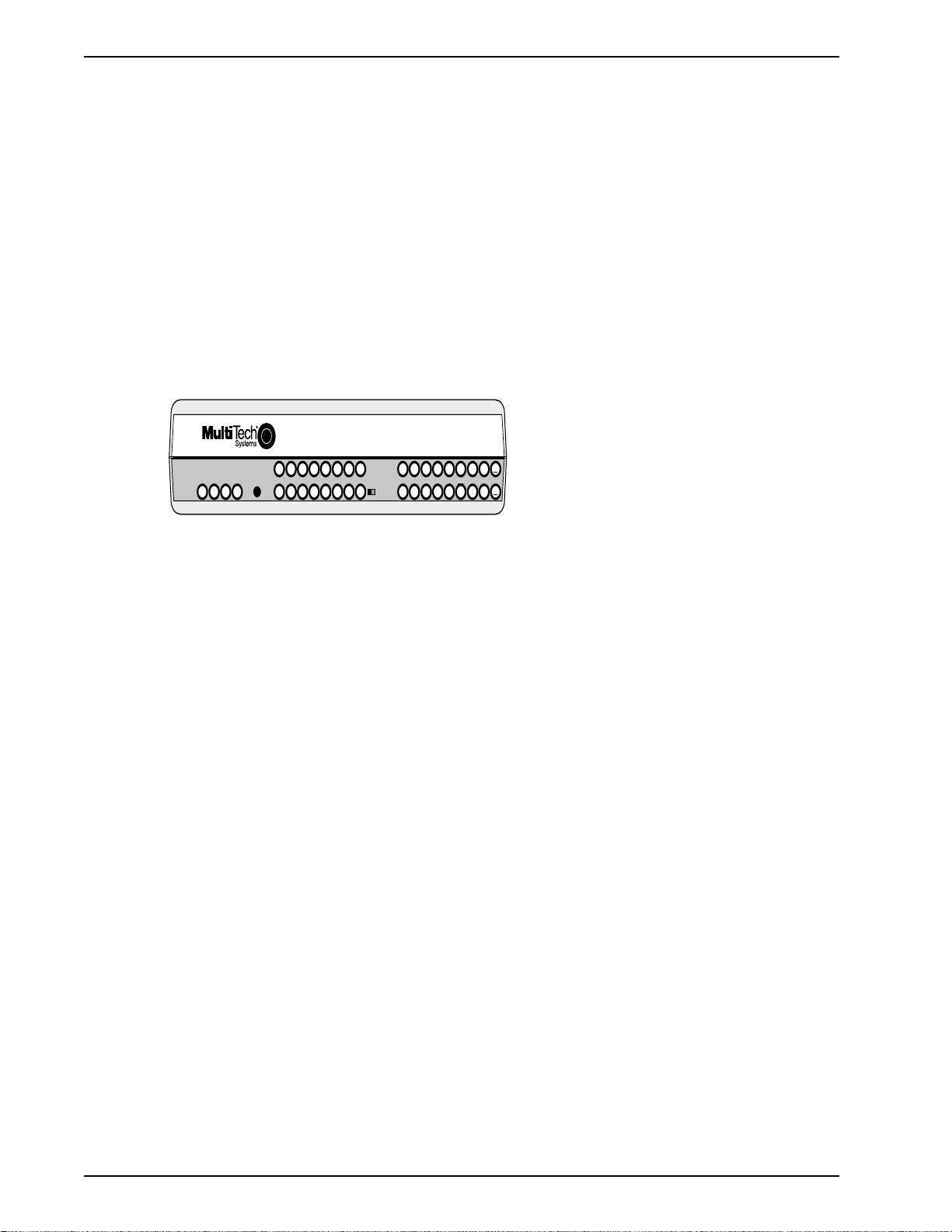
Figure 1-1. DataTalker (Desktop V ersion)
1.2 About This Manual
This manual has eight chapters. There are also several appendices at the end of the manual,
most of which summarize information contained in the chapters. These appendices can be used
as quick references. The information contained in each chapter is as follows:
Chapter 1 - Introduction
This chapter is an introduction to the world of multiplexing. If you already have an extensive
background in multiplexing, this introduction will provide a good review.
Chapter 2 - Configuration Examples
This chapter describes DataTalker configurations and provides examples of how the DataT alker
is typically used. The basic model has a synchronous or asynchronous data channel, a voice/fax
channel, and a composite link supporting synchronous communications. Options include a
second voice/fax channel and an internal V.34 (33.6K bps) modem, 56K bps DSU, or ISDN
terminal adapter.
MultiMux
Data / Voice / Fax Concentrator
RXT FCR RD TM V35 EXT MDM DSU
COMPOSITE
LINK
STATUS
CD RCV XMT CTS 56 RTS NS OOS
101
28.8 OHDBUP
TA
DTR
2B
Chapter 3 - Front and Back Panel Descriptions
Chapter 3 describes the front panel indicators, back panel connections, and switches. The front
panel indicators are grouped into data and command port, voice/fax channels, and composite link
status. The back panel provides all cable connections.
8
Page 9

Chapter 1 - Introduction and Description
Chapter 4 - Unpacking and Configuration
This chapter describes the contents of the shipping container; provides a customizeable
configuration summary; discusses configuration considerations for the data port, voice/fax
channel, and the composite link; and provides a detailed configuration procedure. The
configuration procedure simplifies the process by asking questions about your application, which
allows you to glide through the configuration process by configuring only the items that need to
be changed.
Chapter 5 - Installation
Chapter 5 provides procedures for cabling your DataTalker, moving the V.35 shunt, applying
power, and checking it out. Cabling involves a minimum of three cables. Each cable connection is
explained in detail. If a V.35 interface is used, a procedure on how to move the shunt is provided.
Finally, a power-on and checkout procedure is provided with some suggestions on what to do in
case something goes wrong.
Chapter 6 - Menus
The DataTalker is software driven using menus, and is controlled through a command port
device. This chapter describes the menus and the impact each option has on your system’s
operation.
Chapter 7 - Troubleshooting
This chapter is a guide to troubleshooting your DataTalker. It contains lists of error conditions,
probable causes, and suggested fixes or steps designed to isolate the failing unit in your
communications network.
Chapter 8 - Service, Warranty and Tech Support
Chapter 8 provides instructions on getting service for the DataTalker at the factory; a statement
of the limited warranty; information about our user bulletin board service, and space for recording
information about your DataTalker prior to calling Multi-T ech's Technical Support.
9
Page 10
DataT alker Owner’s Manual
1.3 Product Description
The DataTalker series of multiplexers has a single synchronous or asynchronous data channel, a
command port, one or two voice/fax channels, and a single synchronous composite link with an
internal data service unit (DSU), modem, ISDN terminal adapter, or an external synchronous link
device. The DataTalker can be connected to an asynchronous device such as a PC or host
computer, an external synchronous device such as a LAN router, or the composite link of an
MMH900 series MultiMux. It also can be connected to telephone equipment for voice or fax traffic
over your standard composite link. The DataTalker’s data port allows either synchronous or
asynchronous devices to be connected to it. The command port allows you to configure your data
channel, composite link, and voice mode of operation. The composite link can be configured for
an internal 28.8K bps dial-up/leased line modem, an internal DSU for digital communications over
a digital data service (DDS) network, or an ISDN terminal adapter for Basic Rate Interface
Service. It can also be configured for external synchronous link devices. The voice/fax channel
supports phone, fax, or key telephone system equipment through an FXS interface, a PBX
station-side connection through an FXO interface, or a PBX trunk connection through an E&M
interface. The DT101/V34 and DT102/V34 DataTalkers are dual-function models. If the user
requires traditional data communications, these models provide a simple switch to enable a
standalone V .34 modem mode, which supports dial-in/dial-out data communications for Internet,
BBS, and other on-line access.
PSTN
Trunk
Trunk
Trunk
Station
Station
PBX
1
2
4
3
5
7
6
8
9
Fax/Telephone
Data/
Command
Channel
E&M
FXO
FXS
Configurations
I/O
Channel 1
CODEC
A to D
D to A
EPROM
Data/Command
Processor
RAM
Analog
to
Digital
Digital
to
Analog
Digital
Signal
Processor
AT Commands
Serial
Communications
Controller
Port
RAM
Digitize
Voice/fax
RAM
EPROM
Modem,
DSU, or
Terminal
Adapter
C
Composite
o
Link
m
L
p
i
o
n
s
k
i
t
e
PDN
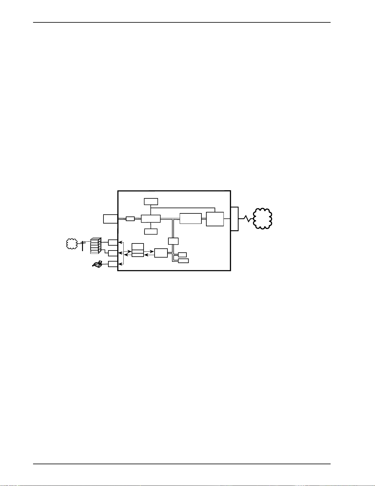
Figure 1-2. Block Diagram
A simplified block diagram of the DataTalker is shown in Figure 1-2. The data channel on the top
left and the voice/fax channel on the bottom left feed data to a serial communications controller
that provides the path through a modem, DSU, or ISDN terminal adapter to the public data
network. The data channel, voice/fax channel, and the serial communications controller are on
the main printed circuit board. The internal modem, DSU, or terminal adapter is a daughter board
that plugs into the main board. The data/command channel is a dual purpose channel to which a
synchronous or asynchronous device can be connected when it is used in its data mode. The
voice/fax channel allows you to connect a telephone, a PBX (Private Branch eXchange)
extension, or a PBX E&M trunk for voice or fax communication. On the other end of the
DataTalker, an internal 33.6K bps modem, 56K bps DSU, or ISDN terminal adapter provides the
composite link interface to the public data network.
The data/command channel can have a terminal or PC connected to it for configuring the
DataTalker. The versatility of the data/command port allows the DataTalker to be connected to a
synchronous or asynchronous device in the data mode or to an asynchronous device in the
command mode when the DataTalker needs to have the configuration of the data channel, voice/
fax channel, or the composite link changed. The data/command channel can be switched
between data and command modes by setting a DIP switch. If the data/command channel is in
data mode, it is also possible to switch to command mode by entering the escape command
+++AT<CR>.
10
Before you can transfer data over the channel, you must connect a terminal or PC running
Page 11

Chapter 1 - Introduction and Description
communications software to the DA TA/COMMAND connector on the back panel and configure
the data channel for the type of data that is going to be transferred. For example, if an
asynchronous device is going to be connected to the data channel, you must set the speed of the
channel, the word length, the number of stop bits, whether or not you are going to have parity
checking, the flow control type, and other aspects of asynchronous data. After you have
configured the data channel, remove the command port device and connect the data channel
device, allowing data to be transferred from the asynchronous device to the MultiMux’s input/
output circuitry .
To operate the data channel in synchronous mode, as when connecting to a remote LAN bridge
or to the composite link of an MMH900 series MultiMux, use the same DATA/COMMAND
connector. The sync device you connect to the data channel must be an SLDC or HDLC device.
Configure the data channel for sync channel operation with any SLDC/HDLC protocol , for
internal or external clocking, and for speed. Configuration information is stored in non-volatile
memory , which informs the data/command processor how data is received from the input/output
(I/O) circuitry .
To set up the DataTalker for voice or fax operation, connect the VOICE/FAX CHANNEL 1 FXS
connector on the back panel to a telephone or fax machine, connect the FXO connector to a PBX
station circuit, or connect the E&M connector to a PBX E&M trunk. The FXS (Foreign eXchange
Station) circuitry in the DataTalker allows a telephone or fax machine to be directly connected to
the DataTalker. This circuitry provides a ringing voltage to the remote instrument when it detects
an off-hook condition from the attached device, so that when two telephones are used, picking up
one of the handsets rings the telephone at the other end. If the FXO (Foreign eXchange Office)
connection is used at one end of the network and a telephone set is used at the other end of the
network, the PBX provides the dial tone, and the remote user can dial a number as if locally
attached to the PBX. The E&M connector is used to link two PBXs.
Before a voice or fax operation can take place, the DataTalker must be configured for the types of
local and remote connections and for the line conditioning for the voice circuitry . The voice/fax
channel is configured in the same way as the data channel: by connecting a command port
device to the DA TA/COMMAND connector on the back panel and setting the voice/fax
configurations. Once the channel is configured, the analog to digital conversion circuitry accepts
the incoming analog signal and converts it to a digital representation of the signal. The digitized
signal is stored in the dual-port RAM for transmission to the serial communications controller
when it requests the dual-port RAM for data. The serial communications controller conditions the
digitized voice or fax data for transmission to the composite link.
In order to transfer data from the serial communications controller over the composite link to the
remote site, the composite link must be configured. Factors to be considered include whether an
external device or an internal modem, DSU, or terminal adapter or installed, the speed of the link,
who is providing the clocking, and other link conditioning factors. The composite link is
configured using a command port device and menus the same way we configured the data and
voice/fax channels. This is accomplished by setting the link configurations to match the link
device installed in the DataTalker and the requirements of the link service and remote system. If,
for example, an internal DSU is installed that will be connected to a DDS network that provides
clocking, the DataTalker detects that the link device is an internal DSU. Through the configuration
stored in nonvolatile memory , it knows that the clocking is going to be provided by the DDS
network. When you look at the versatility of the composite link, many other factors must be
considered, such as answer or originate, two- or four-wire, and dial-up or leased line operation.
But all these considerations are handled in the same manner as the example of the DSU above.
This is basically how your DataTalker is connected to a data device and voice or fax equipment,
how the internal logic is conditioned to transfer data, and how the composite link passes that data
on to the remote site.
11
Page 12

DataT alker Owner’s Manual
1.4 System Features
1.4.1 Voice/Fax
The voice/fax feature of the DataTalker allows you to establish voice or fax traffic on top of your
normal data communications over a composite link, saving the expense of extra communications
lines. The DataTalker provides three types of telephone circuits (FXS, FXO, and E&M) that allow
a telephone, a fax machine, a PBX station card, or a PBX E&M trunk to be directly connected to
it. In one configuration, these telephone circuits cause the telephone at a remote location to ring
when you pick up the handset on the local telephone. In another configuration, an off-site
extension moves your office extension to a remote location. In a third configuration, you can use
the DataTalker to tie two PBXes together.
1.4.2 Data Channel
The DataTalker data channel is able to accommodate any asynchronous device or any SDLC/
HDLC synchronous device. Configuration of the data channel is controlled by menus that
determine the mode of operation (sync or async), whether or not clocking is necessary, the
speed of the channel, and a number of async channel conditioning parameters.
1.4.3 Composite Link
The DataTalker’s composite link is capable of synchronous and full duplex communications with
an internal or external link device. Using an internal modem, ISDN terminal adapter, DSU, or
external device, the DataTalker can be connected to different types of communications links,
such as a dial-up line, a leased line, a Basic Rate Interface (BRI) ISDN service, or a DDS
network. If an external link device is used, the DataTalker can communicate with it using either
the RS232 or V.35 standard.
1.4.4 Flow Control
Flow control regulates the volume of data entering the data port. When the channel buffer is
almost full, a flow control command is issued which tells the device attached to the data port to
stop sending data. The devices on both ends of the link must be configured for the same flow
control method. The most common flow control methods are XON/XOFF and RS232C signal
control (using CTS). The DataTalker supports these and ENQ/ACK.
DATATALKER-INITIATED
FLOW CONTROL
Channel
Device
Flow control stops the input
of data to the DataTalker
DATA DATA
DataTalker DataTalker
CHANNEL DEVICE-
INITIATED PACING
Channel
Device
Pacing stops the output of
data from the DataTalker
1.4.5 Parameter Memory
A nonvolatile memory for storing configurations and options means that the DataTalker remains
configured until you change it. You can configure a DataT alker and save the parameters to
memory, turn it off, ship it, and use it without having to reconfigure it.
12
Page 13

Chapter 1 - Introduction and Description
1.4.6 Diagnostics
Diagnostics in a network are of considerable importance. That is why the DataTalker is equipped
with several diagnostic modes that will test every aspect of the network. The diagnostics include
easy-to-execute tests for the data channel, voice/fax channel, composite link, and various
components of the DataTalker unit itself. The diagnostic tests are executed from a single
diagnostic tests menu by selecting the test number and following any corresponding instructions
given by the DataTalker.
1.4.7 Operational Statistics
Operational statistics provide an activity report of the DataTalker network. Statistics such as
receive-block errors pinpoint composite link device or line problems. Composite link statistics are
displayed in a single screen.
13
Page 14

DataT alker Owner’s Manual
1.5 FCC Regulations for Telephone Line Interconnection
1. This equipment complies with Part 68 of the FCC rules. On the outside surface of this
equipment is a label that contains, among other information, the FCC registration number
and ringer equivalence number (REN). If requested, this information must be provided to the
telephone company.
2. As indicated below the suitable jack (USOC connecting arrangement) for this equipment is
shown. If applicable, the facility interface codes (FIC) and service order codes (SOC) are
shown.
3. The ringer equivalence number (REN) is used to determine the quantity of devices which
may be connected to the telephone line. Excessive RENs on the telephone line may result in
the devices not ringing in response to an incoming call. In most, but not all areas, the sum of
the RENs should not exceed five (5.0). To be certain of the number of devices that may be
connected to the line, as determined by the total RENs, contact the telephone company to
determine the maximum REN for the calling area.
4. If this equipment causes harm to the telephone network, the telephone company will notify
you in advance. But if advance notice isn’t practical, the telephone company will notify the
customer as soon as possible. Also, you will be advised of your right to file a complaint with
the FCC if you believe it is necessary .
5. The telephone company may make changes in its facilities, equipment, operations, or
procedures that could affect the operation of the equipment. If this happens, the telephone
company will provide advance notice in order for you to make necessary modifications in
order to maintain uninterrupted service.
6. If trouble is experienced with this equipment (the model of which is indicated below) please
contact Multi-Tech Systems, Inc. at the address shown below for details of how to have
repairs made. If the trouble is causing harm to the telephone network, the telephone
company may request you remove the equipment from the network until the problem is
resolved.
7. No repairs are to be made by you. Repairs are to be made only by Multi-Tech Systems or its
licensees. Unauthorized repairs void registration and warranty .
8. This equipment cannot be used on public coin service provided by the telephone company .
Connection to Party Line Service is subject to state tariffs. (Contact the state public utility
commission, public service commission or corporation commission for information.)
9. If so required, this equipment is hearing aid compatible.
Manufacturer: Multi-Tech Systems, Inc.
Model Number: DT10x and DT10xR Series
FCC Registration Number: AU7USA-22313-DE-N (DSU)
AU7USA-22271-MM-E (Modem)
Ringer Equivalence: 0.3B (Modem)
Modular Jack (USOC): RJ-1 1 or RJ-48 (single line)
Service Center in U.S.A. Multi-Tech Systems Inc.
2205 Woodale Drive
Mounds View , MN 55112 USA
(612) 785-3500 or (800) 328-9717
Fax (612) 785-9874
14
Page 15

1.6 Canadian Limitations Notice
Notice: The Canadian Department of Communications label identifies certificated equipment. This
certification means that the equipment meets certain telecommunications network protective,
operational and safety requirements. The department does not guarantee the equipment will
operate to the user’s satisfaction.
Before installing this equipment, users should ensure that it is permissible to be connected to the
facilities of the local telecommunications company . The equipment must also be installed using
an acceptable method of connection. In some cases, the company’s inside wiring associated with
a single line individual service may be extended by means of a certified connector assembly
(telephone extension cord). The customer should be aware that compliance with the above
conditions may not prevent degradation of service in some situations.
Repairs to certified equipment should be made by an authorized Canadian facility designated by
the Supplier. Any repairs or alterations made by the user to this equipment; or equipment
malfunctions, may give the telecommunications company cause to request the user to disconnect
the equipment.
Users should insure for their own protection that the electrical ground connections of the power
utility , telephone lines and internal metallic water pipe system, if present, are connected together.
This precaution may be particularly important in rural areas.
Chapter 1 - Introduction and Description
Caution: Users should not attempt to make such connections themselves, but should contact the
appropriate electric inspection authority , or electrician, as appropriate.
The Load Number (LN) assigned to each terminal device denotes the percentage of the total
load to be connected to a telephone loop which is used by the device, to prevent overloading.
The termination on a loop may consist of any combinations of devices subject only to the
requirement that the total of the Load Numbers of all the devices does not exceed 100.
The load number for the composite link modem is 4.
15
Page 16

DataT alker Owner’s Manual
1.7 Specifications
1.7.1 Async Data Channel
Number of Channels One
Maximum Speed 1 15,200 bps
Channel Speed All standard speeds from 300 bps to 1 15,200 bps
Data Format 5, 6, 7, or 8 data bits, with 1, 1.5, or 2 stop bits
Parity Odd, even, or none
Local Echo On or off selectable
Flow Control XON/XOFF, CTS, or HP ENQ/ACK selectable
Pacing On or off selectable, RTS on/off, or XON/XOFF
Interface RS-232D/ITU-T V.24; DB-25 female connector
1.7.2 Sync Data Channel
Data Format Synchronous
Channel Speed Up to 128K bps
Protocol SDLC/HDLC
Error Correction 16-bit CRC block check with ARQ
Interface RS-232D/ITU-T V.24; DB-25 female connector
1.7.3 System Control (Command Port)
Local Access Through DataTalker’ s RS232C command port
Device Any asynchronous keyboard terminal or PC in terminal mode (local
access only)
Menus Menus to configure data channel, voice/fax channel(s), and
composite link. Statistics menu and test menus are provided to
monitor performance and diagnose problems.
Diagnostics Data or voice loopback, memory , watch dog tests, and DIP switch
definitions and settings
1.7.4 Composite Link
Number of Links One
Data Format Synchronous
16
Link Speeds Up to 256K bps
Link Protocol Proprietary modified HDLC
Error Correction 16-bit CRC block check with ARQ
Interface RS-232D/V.24 or ITU-T V.35, or use DataTalker integral modem,
DSU, or ISDN terminal adapter
Page 17

Chapter 1 - Introduction and Description
1.7.5 Internal Modem
Modulation ITU-T V.34; AT&T V.32 terbo; ITU-T V.32bis, V.32, V.22bis, V.22; Bell
212A and 103 (North America) or V.23 and V.21 (international)
Speeds 300 bps to 33.6K bps
Commands Fully AT command compatible
Usage Synchronous full duplex over unconditioned 2-wire or 4-wire leased
line; asynchronous half or full duplex over 2-wire dial-up
Line Interface RJ-1 1C jack for dial-up and 2-wire or 4-wire leased line; in Canada,
one CA02B connector
1.7.6 Internal DSU
Speed 56K, 19.2K, 9.6K, 4.8K, or 2.4K bps
Format Synchronous DDS or compatible
Usage Full duplex over LADS (Local Area Data Set) or two-pair non-loaded
metallic wire
Line Interface DDS interface with an RJ-48 keyed jack
1.7.7 ISDN Terminal Adapter
Description Integral ISDN terminal adapter card
Operating Mode ISDN Basic Rate; 1B+D or 2B+D
Synchronous Data Rates 2.4–128 Kbps
Clocking Normal network clock (slaved to network receive clock); private
network master (internal); external clock of DTE data
Commands Menu system
D-Channel Switch A T&T 5ESS®, 5E6; NT DMS-100™, BCS-32;
Compatibility Siemens Stromberg-Carlson EWSD®, National ISDN-1;NEC
International Switch
Line Interface 2-wire ISDN Basic Rate 2B1Q U-interface; ANSI T1.601-1992
compliant; RJ-48 jack
B-Channel Aggregation BONDING Protocol, Mode 1
1.7.8 Voice/Fax Channel
Number of Channels One or two channels
Voice Digitization Rates 9600 and 16K bps
Automatic Fax Group 3 fax rates
Modulation/Demodulation (2400, 4800, 7200 and 9600 bps)
Analog Interfaces FXS, FXO, and E&M (channel 1 only)
Signaling DTMF
Line Interface FXS and FXO: RJ-11 jacks
E&M: RJ-48 jack
17
Page 18

DataT alker Owner’s Manual
1.7.9 Electrical/Physical
Desktop Models:
Power Supply Input 100 to 250 VAC
Power Supply Output +5v@5A, +12v@1A, -12v@0.5A
Power Consumption 20 watts
Dimensions 2.3" high x 9" wide x 12.8" deep
Weight 7 pounds (3.2 kg)
Rack-mount Models:
Power Supply Input 100 to 250 VAC
Frequency 47 to 63 Hz
Power Consumption 20 watts
Dimensions 2.00" high x 9. 98" wide x 12.75" deep
5.7 cm high x 22.9 cm wide x 32.7 cm deep
5.1 cm high x 25.2 cm wide x 32.4 cm deep
Weight 5 pounds (2.3 kg)
18
Page 19

Chapter 2 - Configuration
Page 20

DataT alker Owner’s Manual
2.1 Introduction
The Multi-Tech DataT alker is available in both desktop (DT10x) and rack-mount (DT10xR)
versions. The desktop version is designed for home office applications. It is mounted in a
horizontal cabinet and has an external power supply , a power switch, an originate switch, and a
switch that allows you to use it also as a stand-alone modem or terminal adapter. The rack-mount
version is designed for main office applications. It is mounted for vertical insertion into a MultiTech RackTalker rack, has an internal power supply, is hot-swappable, and has a reset switch.
Otherwise, they are identical. DataTalkers are available with a synchronous or asynchronous
data channel, one or two voice/fax channels, and an optional internal composite link V.34
modem, 56K bps DSU, or 2B+D link ISDN terminal adapter.
DataTalker Configurations
Desktop Models:
Base Model with...
No Additional Options
Installed
33.6K bps Modem DT101/V34 DT102/V34
56K bps DSU DT101/56 DT102/56
2B+D ISDN Terminal
Adapter
Rack-Mount Models:
Base Model with...
No Additional Options
Installed
33.6K bps Modem DT101R/V34 DT102R/V34
56K bps DSU DT101R/56 DT102R/56
2B+D ISDN Terminal
Adapter
1 Data Channel & 1
Voice/Fax Channel
DT101 DT102
DT101/IS DT102/IS
1 Data Channel & 1
Voice/Fax Channel
DT101R DT102R
DT101R/IS DT102R/IS
1 Data Channel & 2
Voice/Fax Channels
1 Data Channel & 2
Voice/Fax Channels
20
Valid Voice/Fax Configurations:
Configuration Description
E&M to E&M Any phone or fax machine connected to the PBX at one site can call
any phone or fax machine connected to the PBX at the other end.
FXS to FXS No number must be dialed. If the phone or fax machine on one end
goes off hook, the phone or fax machine on the other end rings.
FXS to FXO The phone and fax machine at the FXS site act as though they are
extensions of the PBX at the FXO site.
Page 21
2.2 Configuration 1 - Dial-Up Link
Configuration 1 is a dial-up link using a pair of DataTalkers to provide data communications
between a home office PC and the main office host computer and telephone services through the
main office telephone system. The data and telephone services are provided using a single line
between the home office and the main office. In this application, the main office DataTalker is tied
to a host computer via an async channel, and the data channel of the home office DataTalker is
connected to the serial port of the home office PC. The composite link is provided by internal
33.6K modems in a dial-up configuration. All of the telephone services of the main of fice are
supplied to the home office as if the home office was directly connected to the main office
telephone system.
Asynchronous
Channel
Composite Link
PSTN
Data / Voice / Fax Concentrator
VOICE /
RXTFCR RD TMV35 EXTMDMDSU
RSGXSGRCVXMTFAXE&MFXOFXS
TA
FAX 2
COMPOSITE
LINK
DTR
28.8 OHDBUP
STATUS
VOICE /
DATA/
ORIG
FXSFXO E&MFAX XMTRCV XSGRSGCOMXMTRCV FC
CD RCVXMTCTS 56 RTSNS OOS
2B
FAX 1
COMMAND
101 MDM/TA
DataTalker
Telephone
DATA/
COMMAND
PSTN
Voice/Fax
Channel
Trunk
Trunk
Trunk
Station
Station
PBX
Data / Voice / Fax Concentrator
VOICE /
RXTFCR RD TMV35 EXTMDMDSU
RSGXSGRCVXMTFAXE&MFXOFXS
FAX 2
COMPOSITE
LINK
DTR
28.8 OHDBUP
STATUS
VOICE /
ORIG
FXSFXO E&MFAX XMTRCV XSGRSGCOMXMTRCV FC
CD RCVXMTCTS 56 RTSNS OOS
FAX 1
101 MDM/TA
DataTalker
Voice/Fax
Channel
Asynchronous
Channel
TA
2B
Telephone
Home Office
Chapter 2 - Configuration
PC
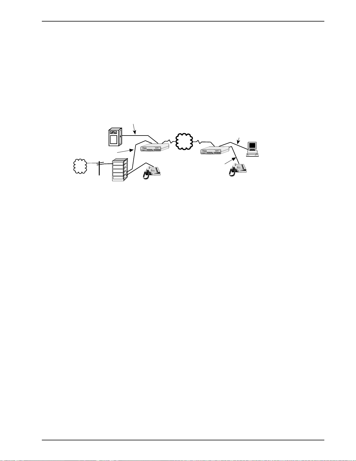
Figure 2-1 Dial-Up Link
To set up this configuration, connect the main office DataTalker to the host computer, to the inoffice telephone system (PBX), and to the public switched telephone network (PSTN). Connect
the home office DataTalker to the serial port of your PC, to a telephone set, and to your local
telephone line. You must also connect a terminal or a PC running communications software (such
as Multi-Tech’s MultiExpress™ for DOS) to the dual function data/command port and configure
the DataTalkers. Configure the DataTalker for the main office application; i.e., set up the voice/fax
channel for a local interface of FXO and a remote interface of FXS. Configure the home office
unit for DTR dialing of the main office DataTalker, a local interface of FXS, and a remote interface
of FXO.
You must configure the DataTalkers before you connect them to the computers. T o configure a
DataTalker, place DIP switch position 3 in the down (closed) position and connect a command
port device such as a terminal or a PC to the DATA/COMMAND connector on the back of the
DataTalker. T urn on the DataTalker and PC and run your communications software in terminal
mode. (Set it for direct connection at a serial port speed of 19,200 bps or slower.) Press the
ENTER key to establish communications with DataTalker and see the Main Menu.
A series of configuration menus provides simple and complete configuration information for each
aspect of the DataTalker. Using the menus, we will configure one DataTalker for the main office
and the second one for the home office.
The menus flow from the Main Menu through the Configurations menu to configuration menus for
specific parts of the DataTalker. From the Configurations menu you will use the first menu to
configure the data port of the main office unit to talk to the host computer , and that of the home
office unit to talk to the async channel of the home office PC. You will use the next one to
configure the voice/fax channel for connection of the main office DataTalker to an extension of
the local PBX, and the home office DataTalker to your telephone and your local telephone
service. You will use the final group of configuration menus to set up the internal MMH2834
modem to dial the main office from the home office and for the main of fice to answer the call.
As you go through these configuration menus, you must supply the specifics of your
configuration.
21
Page 22

DataT alker Owner’s Manual
When you established communication, the Main Menu appeared. From the Main Menu you can
configure the unit, display statistics, reset various functions within the DataTalker, and run
diagnostic tests:
Main Menu
1 - Configurations
2 - Statistics
3 - Reset Options
4 - Diagnostics
5 - Exit Command Mode
6 - QUICK SETUP
Selection : _
To configure the DataTalker, enter 1 and press ENTER.
The Configurations menu is displayed. From this menu you can configure the data port, voice/fax
channel(s), or the composite link. You can also select various factory defaults and store your
current configuration:
Configurations
1 - Data Port Configuration
2 - Voice/Fax Channel(s) Configuration
3 - Composite Link Configuration
4 - Factory Default Configuration Options
5 - Configure Remote Unit
S - Store All Configurations
M - Main Menu
P - Previous Menu
Selection : _
For the main office and the home office units, let’s use the default data port configuration. If your
specific configuration requires that the data port be set up differently , select the option and
choose the new parameter.
From the Configurations menu, select option 2, Voice/Fax Channel(s) Configuration, to configure
the voice/fax channels. For the main office, set up the local interface type (option 6) for an FXO
connection. For the remote interface type (option 1 1), accept the default FXS connection. For the
other selections, accept the defaults .
Voice/Fax Channel 1 Configuration
1 - Destination Channel : 1
2 - Digitizing Rate : 9600
3 - Output Level Atten. : 12
4 - Input Level Gain : 03
5 - Silence Suppression : Off
6 - Local Interface Type : FXS
7 - Ground/Loop Start (FXS) : Loop
8 - 2 or 4 Wire (E&M) : N/A
9 - Dialtone/Wink (E&M) : N/A
10 - Wink Timer (E&M) : N/A
11 - Remote Interface Type : FXS
12 - Ground/Loop Start (FXS) : Loop
13 - 2 or 4 Wire (E&M) : N/A
14 - Dialtone/Wink (E&M) : N/A
S - Store All Configurations
M - Main Menu
P - Previous Menu
Selection : _
22
Page 23

Chapter 2 - Configuration
Enter S and press ENTER to store all configurations for the main office.
Set up the home office unit the same way, except that you should switch the local and remote
interface types (FXS for the local interface and FXO for the remote interface). After you select the
home office options, enter S to store all configurations. Enter P to return to the Configurations
menu.
At the Configurations menu, select option 3, Composite Link Configuration. The composite link
settings for the MMH2834 internal modem are displayed.
The main office will be set up to receive a call from the home office. The home of fice will be set
up for DTR Dialing of the phone number at the main office.
Composite Link Settings - Internal MMH2834
1
- Enter AT commands to 2834
2 - On-Line XMT Rate: 28800
3 - Speed Setting: 33600
-
Dial/Leased: Dial
4
5 - 2 or 4 Wire: 2 Wire
Answer/Originate: Answer
6 7 - Transmit Level -10db
8 - DOD/DOI: On
9 - DOI Timer: 03min
10 - DOD Toggle DTR: 40sec
S - Store All Configurations
M - Main Menu
P - Previous Menu
Selection : _
Set up the main office unit to use the default composite link settings. Set up the home office unit
for DTR dialing. To set up for DTR dialing, select option 1, Enter AT Commands to 2834, and
enter the following AT commands:
ATDT[Number to Dial]N0 <CR>
AT$D1 <CR>
AT&W <CR>
Q <CR>
ATDT[Number to Dial]N0 is the AT command to store the main of fice phone number in location
N0. The AT$D1 command sets the modem for DTR dialing when the home office DataT alker is
powered up. The AT&W stores the $D1 command as a user default. The Q command returns you
to the Composite Link Settings menu. <CR> is shorthand for a carriage return (press ENTER).
Enter S and press ENTER to store the new configuration.
This completes the configuration of both DataTalkers. The main office DataTalker can now be
connected to the host computer, PBX, and phone line. The home of fice DataTalker can be taken
home.
To connect the main office DataTalker, first disconnect the PC or terminal from the DATA/
COMMAND connector on the DataTalker. Place DIP switch position 3 in the OPEN (up) position
to change the data/command port over to the data channel. Connect an RS232C cable between
the DATA/COMMAND connector on the DataTalker and an asynchronous port on the host
computer. Connect an RJ-11 phone cable from the VOICE/FAX CHANNEL 1 FXO connector on
the back panel to the station side of the PBX. Connect an RJ-1 1 phone cable between the DIALUP jack on the DataTalker and the dial-up phone line.
23
Page 24

DataT alker Owner’s Manual
To connect the home office DataTalker to its PC, connect an RS232C cable between the DATA/
COMMAND connector on the DataTalker and an async port on the PC (typically, COM1 or
COM2). Place DIP switch position 3 on the side of the DataTalker in the OPEN (up) position to
enable the data channel.
To connect your home telephone to the DataTalker, remove the telephone cable from the wall
jack and connect it to the VOICE/FAX CHANNEL 1 FXS connector on the DataTalker. Connect a
second RJ-1 1 phone cable between the Dial-Up jack on the DataTalker and your wall jack.
The home office DataTalker is now ready to communicate with the main office. When you power
on the home office DataTalker, the internal MMH2834 modem dials the previously stored number
for the main office. The OH (Off-Hook) LED lights, indicating that the modem is active. After the
main office DataTalker answers, the CD (Carrier Detect) LED lights and the RD (Remote Down)
LED goes off. At this point, voice and data communication can begin.
If you do not configure the DataTalker for DTR dialing, there is an alternate way to dial the main
office computer . Connect a phone to the FXS jack and a dial-up phone line to the internal
composite link DIAL-UP jack. Pick up the receiver and listen for a dial tone, then dial the main
office number . When you hear the answer tone, press and release the Originate switch on the
DataTalker’s front panel. The OH light will come on, then the modem will handshake and connect.
Hang up the phone and data communications will proceed normally .
24
Page 25
Chapter 2 - Configuration
2.3 Configuration 2 - MMH900 Series with Voice/Fax
Configuration 2 adds voice capability to an existing data-only network using the same composite
link. The example shown in Figure 2-2 had an existing data-only network consisting of a MultiMux
MMH904C multiplexer connected to a host computer at the local site and a second MMH904C
connected to terminals and/or PCs and a shared printer at the remote site. To add voice
capability, a DataTalker is added between the composite link of the MMH904 and the public data
network (PDN) at both sites. The composite link between the two sites is now moved from the
MMH904 multiplexer to the new DataTalker. The composite link of the MultiMux MMH904 is
reconfigured as an external synchronous link device and connected to the synchronous data
channel of the DataTalker. The voice capability is added by connecting a telephone to the FXS
port on the back panel of the DataTalker at each site and configuring the voice/fax channel of the
DataTalkers for FXS to FXS. Now, while you are transferring data over the composite link, you
can pick up the telephone and have a simultaneous voice conversation.
Asynchronous
Channel
CD
CD
RCV
MultiMux MMH904
Voice/Fax
Channel
R
F
BUFFER
L
E
FULLNESS
O
T
LEVEL
C
R
T
A
R
N
L
S
R
M
Channel Eight
C
Channel SixChannel Seven
Channel Five
Command Modem
IT
2
1
3
V
RCV
XMT
OH
RCV
XMT
XMTRCV XMTRCV XMTRCV
DTR
Internal Composite Link
External Composite Link
Channel one
Channel TwoChannel ThreeChannel Four
CTS
XMT
V.35
RCV
XMTRCV
RCVXMTXMTRCV
XMT
MMH2834 CD RCV XMT CTS 28.8 24.0 19.2 14.4 OH TR EC DBUP
DSU CD RCV XMT CTS 56 19.2 RTS NS OOS TM
V29/V33 Modem CD RCV XMT CTS
Local Site
R
L
E
I
M
N
O
K
T
E
A
L
D
A
W
R
N
M
Telephone
Sync Data
Channel
VOICE /
FAX 2
VOICE /
FXSFXO E&MFAXXMT RCVXSGRSGCOMXMTRCV FC
FAX 1
Data / Voice / Fax Concentrator
RXTFCR RDTM V35EXTMDM DSU
RSGXSGRCVXMTFAXE&MFXOFXS
TA
COMPOSITE
LINK
28.8 OHDBUP
DTR
STATUS
CDRCV XMTCTS56 RTSNS OOS
2B
101 MDM/TA
Composite Link
PDN
DATA/
COMMAND
A
INTERNAL LINK DEVICE
T
S
E
(Modems)
Y
S
M
MultiTech
5
V
T
N
M
6
2
C
Systems
H
K
9
2
/
M
L
D
8
V
O
I
S
D
3
3
N
U
E
3
K
4
MultiMux
Statistical Multiplexer
DATA/
ORIG
COMMAND
DataTalker
Data / Voice / Fax Concentrator
VOICE /
RXTFCR RDTM V35EXTMDM DSU
RSGXSGRCVXMTFAXE&MFXOFXS
FAX 2
COMPOSITE
LINK
STATUS
VOICE /
CDRCV XMTCTS56 RTSNS OOS
ORIG
FXSFXO E&MFAXXMT RCVXSGRSGCOMXMTRCV FC
FAX 1
101 MDM/TA
DataTalker
TA
28.8 OHDBUP
DTR
2B
Sync Data
Channel
Command Modem
RCV
CD
External Composite Link
CD
RCV
MultiMux MMH904
Asynchronous
Channel
A
INTERNAL LINK DEVICE
T
R
R
F
L
BUFFER
S
L
E
E
E
I
FULLNESS
(Modems)
O
M
Y
S
N
T
LEVEL
M
MultiTech
5
V
C
O
T
N
K
R
M
6
2
T
T
C
A
Systems
H
K
R
E
9
A
N
L
2
/
L
M
L
S
R
D
D
A
8
V
O
I
M
Channel Eight
C
W
Channel SixChannel Seven
S
R
Channel Five
D
3
3
N
IT
2
1
3
V
N
M
U
E
3
K
4
XMT
OH
RCV
XMT
XMTRCV XMTRCV XMTRCV
DTR
MultiMux
Internal Composite Link
Channel one
Channel Three
Channel Two
Channel Four
Statistical Multiplexer
CTS
XMT
V.35
RCV
XMTRCV
RCVXMTXMTRCV
XMT
MMH2834 CD RCV XMT CTS 28.8 24.0 19.2 14.4 OH TR EC DBUP
DSU CD RCV XMT CTS 56 19.2 RTS NS OOS TM
V29/V33 Modem CD RCV XMT CTS
Voice/Fax
Channel
Telephone
Remote Site
Printer
Figure 2-2. Adding Voice to Data-Only Network
The async channels of the MultiMux MMH904s operate the same way as in the data-only
network. The MMH904 is reconfigured for an external link device by changing the 8-position DIP
switch position 2 to the down (closed) position, ensuring that the composite link is configured for
sync mode, and setting clocking to External. An RS232C cable can now be connected to the
COMPOSITE LINK EXTERNAL RS232C/V.35 connector on the back panel of the MMH904.
The composite link connection of the DataTalker to the PDN depends on the type of link device
being used. If the link device is an internal 33.6K bps modem, connect the Modem DIAL-UP or
LEASED connector to the PDN. If the link device is an internal DSU or ISDN terminal adapter,
connect the DSU/TA DIGITAL connector to the PDN. If an external link device is used, cable it to
the EXTERNAL COMPOSITE RS232C/V.35 connector. The connection type depends on whether
the interface of the external link device is RS232C or V.35. If it is V.35, a shunt on the main board
of the DataTalker must be moved to the V .35 position.
You must configure the DataT alker before you connect it to the MultiMux MMH904. To configure
the DataTalker, place DIP switch position 3 in the down (closed) position and connect a command
port device such as a terminal or a PC to the DATA/COMMAND connector on the back of the
DataTalker. T urn on the DataTalker and PC and run your communications software in terminal
mode. (Set it for direct connection at a serial port speed of 19,200 bps or slower.) Press the
ENTER key to establish communications with DataTalker and see the Main Menu.
25
Page 26

DataT alker Owner’s Manual
A series of configuration menus provides simple and complete configuration information for each
aspect of the DataTalker. From the Main Menu, you can access menus to configure the unit,
display statistics, reset various functions within the DataTalker, and run diagnostic tests:
Main Menu
1 - Configurations
2 - Statistics
3 - Reset Options
4 - Diagnostics
5 - Exit Command Mode
6 - QUICK SETUP
Selection : _
To go to the Configurations menu, enter 1 and press ENTER. The Configurations menu appears.
From this menu you can configure the data port, voice/fax channel(s), or the composite link. This
menu also allows you to select various factory defaults and store your current configuration.
Configurations
1 - Data Port Configuration
2 - Voice/Fax Channel(s) Configuration
3 - Composite Link Configuration
4 - Factory Default Configuration Options
5 - Configure Remote Unit
S - Store All Configurations
M - Main Menu
P - Previous Menu
Selection : _
For configuration 2, start by configuring the data port. Enter 1 and press ENTER. The Data Port
Configuration menu appears:
Data Port Configuration
1 - Async/Sync: Async
2 - Speed: 19200
3 - Word Length: 8
4 - Stop Bits: 1
5 - Parity: None
6 - Flow Control: CTS
7 - Enq/Ack Flow Control: Off
8 - Echo: Off
9 - Pacing: Off
10 - EIA Pass Through: Off
11 - Pass Xon: Off
S - Store All Configurations
M - Main Menu
P - Previous Menu
Selection : _
26
Page 27

Chapter 2 - Configuration
The data port in this configuration will be set up for synchronous operation. To configure the data
port for sync operation, enter 1 (Aysnc/Sync) option and change the default Async to Sync. The
data port configuration menu displays the sync parameters.
Data Port Configuration
1 - Async/Sync: Sync
2 - Speed: 19200
3 - Clocking: Internal
4 - Idle Condition: Flags
5 - NRZ/NRZI Encoding: NRZ
6 - CRC Preset: All 1s
7 - Inter-frame Timer: Off
Store All Configuations
S M - Main Menu
P - Previous Menu
Selection : _
Enter 2 and press ENTER to set the speed of the sync data port. Select the appropriate speed
by entering its menu list number. The speed you select should be no faster than the composite
link speed. At the sync data port configuration menu, determine who is supplying the clocking.
The default internal clocking allows the DataTalker to supply the clock. Enter the letter S to store
all configurations and then press P to return to the previous menu.
For configuration 2, where both sites have a telephone connected to the DataTalker, initially
accept the defaults for the second choice in the Configurations menu, Voice/Fax Channels
Configuration.
At the Configurations menu, enter 3 and press ENTER to display the Composite Link Settings
menu.
The DataTalker detects the type of link device being used from the way a DIP switch is set or by
reading the device when it is installed on the main PC board. In this configuration, a 56K bps
internal DSU is being used as the composite link device. So, when the internal composite link
settings menu is displayed, it is for a DSU:
Composite Link Settings - Internal DSU
1 - Speed: 56k
2 - Clocking: DDS
S - Store All Configurations
M - Main Menu
P - Previous Menu
Selection : _
The internal DSU has two options: speed and clocking. The speed option should match the DDS
line speed. The clocking option depends on how you have set up your link with the telephone
company. If the link is set up as a DDS link, use the default DDS setting. If the link is set up for
the DataTalker to provide the clocking, change the clocking option to Internal.
This completes the configuration of both DataTalkers. Disconnect the data/command port from
the terminal or PC and connect it to the composite link of the MMH904. Place DIP switch position
3 on both DataTalkers in the up (OPEN) position to change the data/command port over to a data
channel.
27
Page 28
DataT alker Owner’s Manual
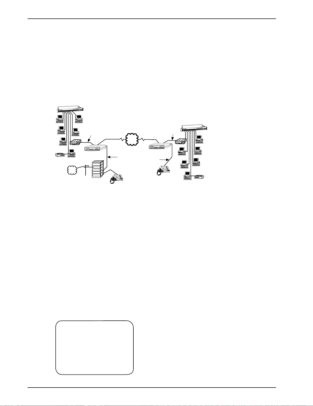
2.4 Configuration 3 - LAN to LAN
Configuration 3 is an example of a pair of DataTalkers providing the link between two LANs with
the added benefit of voice or fax traffic over the same composite link. Bridging the LANs over a
single high speed composite link expands the capacity of each LAN. The LAN bridge on each
LAN is provided by a router/bridge with a synchronous interface connected to the DataTalker’s
data channel. The composite link could be an internal ISDN terminal adapter , an internal 56K
DSU, or one of a variety of external high speed link devices up to fractional T1 devices. The
additional feature provided by the DataTalkers is free voice or fax traffic without the need to
establish a separate voice connection between the two LANs.
Ethernet
Concentrator
LAN PC
File Server
®
h
c
e
T
stems
Sy
Router/Bridge
Print Server
PSTN
Communications
Server
COMMAND
LAN 1
Sync Data
Channel
VOICE /
RSGXSGRCVXMTFAXE&MFXOFXS
FAX 2
VOICE /
DATA/
ORIG
FXSFXO E&MFAXXMT RCVXSG RSGCOMXMTRCVFC
FAX 1
101 MDM/TA
DataTalker
Trunk
Station
Station
Data / Voice / Fax Concentrator
RXTFCR RDTM V35EXT MDMDSU
COMPOSITE
LINK
STATUS
CDRCV XMTCTS 56RTS NSOOS
Trunk
Trunk
PBX
Composite Link
Sync Data
PDN
Data / Voice / Fax Concentrator
VOICE /
RXTFCR RDTM V35EXT MDMDSU
TA
RSGXSGRCVXMTFAXE&MFXOFXS
FAX 2
COMPOSITE
LINK
DTR
28.8 OHDBUP
STATUS
VOICE /
DATA/
ORIG
FXSFXO E&MFAXXMT RCVXSG RSGCOMXMTRCVFC
CDRCV XMTCTS 56RTS NSOOS
2B
FAX 1
COMMAND
TA
28.8 OHDBUP
DTR
2B
Voice/Fax
Channel
DataTalker
Voice/Fax
Channel
101 MDM/TA
Telephone
Telephone
LAN PC
LAN PC
Printer
Channel
Router/Bridge
Communications
®
h
c
e
T
s
tem
ys
S
Server
File Server
LAN 2
Ethernet
Concentrator
Print Server
LAN PC
LAN PC
LAN PC
Printer
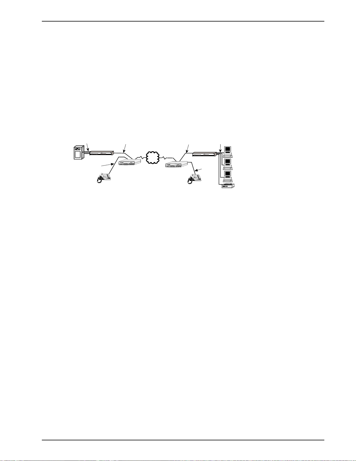
Figure 2-3. LAN to LAN Configuration
In the configuration shown in Figure 2-3, the voice/fax channel 1 FXO port on the DataTalker at
LAN 1 is connected to a station card on the local PBX, and the voice/fax channel 1 FXS port on
the DataTalker at LAN 2 is connected to a telephone. On both ends, the data channel of the
DataTalker is connected to the router’s synchronous port, and the router’ s Ethernet port is
connected to the Ethernet concentrator. An RJ-48 telephone cable connected to the composite
link at the DataTalker’s DSU/TA DIGITAL connector links the DataTalker’s internal DSU to the
public data network.
You must configure the DataT alkers before you connect them to the LANs. To configure a
DataTalker, place DIP switch position 3 in the down (closed) position and connect a command
port device such as a terminal or a PC to the DATA/COMMAND connector on the back of the
DataTalker. T urn on the DataTalker and PC and run your communications software in terminal
mode. (Set it for direct connection at a serial port speed of 19,200 bps or slower.) Press the
ENTER key to establish communications with DataTalker and bring up the Main Menu.
A series of configuration menus provides simple and complete configuration information for each
aspect of the DataTalker. From the Main Menu, you can configure the unit, display statistics,
reset various functions within the DataTalker, and run diagnostic tests:
Main Menu
1 - Configurations
2 - Statistics
3 - Reset Options
4 - Diagnostics
5 - Exit Command Mode
6 - QUICK SETUP
28
Selection : _
Page 29

Chapter 2 - Configuration
To configure the DataTalker, enter 1 and press ENTER.
The Configurations menu is displayed. From this menu you can configure the data port, voice/fax
channel(s), or the composite link. You can also select various factory defaults and store your
current configuration:
Configurations
1 - Data Port Configuration
2 - Voice/Fax Channel(s) Configuration
3 - Composite Link Configuration
4 - Factory Default Configuration Options
5 - Configure Remote Unit
S - Store All Configurations
M - Main Menu
P - Previous Menu
Selection : _
For configuration 3, let’s start by configuring the data port. Enter 1 and press ENTER. The Data
Port Configuration menu is displayed:
Data Port Configuration
1 - Async/Sync: Async
2 - Speed: 19200
3 - Word Length: 8
4 - Stop Bits: 1
5 - Parity: None
6 - Flow Control: CTS
7 - Enq/Ack Flow Control: Off
8 - Echo: Off
9 - Pacing: Off
10 - EIA Pass Through: Off
11 - Pass Xon: Off
S - Store All Configurations
M - Main Menu
P - Previous Menu
Selection : _
Since the data port in this configuration is going to be set up for synchronous operation, only two
options apply: Clocking and Speed. Enter 1 and press ENTER to change to the synchronous
mode of operation. At the Sync Data Port Configuration menu, select the appropriate speed by
entering its menu list number. Use caution when setting the speed—the sync data channel could
very easily overrun the composite link if the speed is set too high. Enter 2 and press ENTER to
change the clocking to internal, which allows the DataTalker to provide the clock.
29
Page 30

DataT alker Owner’s Manual
Data Port Configuration
1 - Async/Sync: Sync
2 - Speed: 19200
3 - Clocking: Internal
4 - Idle Condition: Flags
5 - NRZ/NRZI Encoding: NRZ
6 - CRC Preset: All 1s
7 - Inter-frame Timer: Off
Store All Configuations
S M - Main Menu
P - Previous Menu
Selection : _
Press P to return to the Data Port Configuration menu, enter S to store all configurations, and
then press P again to return to the previous menu. At the Configurations menu, enter 2 and press
ENTER.
The Voice/Fax Channel 1 Configuration menu is displayed. For LAN 1, set voice/fax channel 1 for
an FXO connection as the local interface type (option 6), and keep the default FXS as the remote
interface type (option 11). LAN 2 must be set just the opposite (FXS for the local interface and
FXO for the remote interface). For the other selections, accept the defaults .
Voice/Fax Channel 1 Configuration
1 - Destination Channel : 1
2 - Digitizing Rate : 9600
3 - Output Level Atten. : 12
4 - Input Level Gain : 03
5 - Silence Suppression : Off
6 - Local Interface Type : FXS
7 - Ground/Loop Start (FXS) : Loop
8 - 2 or 4 Wire (E&M) : N/A
9 - Dialtone/Wink (E&M) : N/A
10 - Wink Timer (E&M) : N/A
11 - Remote Interface Type : FXS
12 - Ground/Loop Start (FXS) : Loop
13 - 2 or 4 Wire (E&M) : N/A
14 - Dialtone/Wink (E&M) : N/A
S - Store All Configurations
M - Main Menu
P - Previous Menu
Selection : _
Enter S and press ENTER to store all configurations for LAN 1.
Set up LAN 2 in the same manner, but switch the local and remote interface types (FXS for the
local interface and FXO for the remote interface). When you have finished selecting the LAN 2
options, enter S to store all configuration. Enter P to return to the Configurations menu.
At the Configurations menu, enter 3 and press ENTER to display the composite link configuration
menu.
30
Page 31

Chapter 2 - Configuration
The DataTalker knows the type of link device being used by the way a DIP switch is set or by
detecting a device installed on the main PC board. In this configuration, a 56K bps internal DSU
is used for the composite link device, so when the Composite Link Settings menu is displayed, it
is for a DSU:
Composite Link Settings - Internal DSU
1 - Speed: 56k
2 - Clocking: DDS
S - Store All Configurations
M - Main Menu
P - Previous Menu
Selection : _
The internal DSU has three options: speed and clocking. The speed option should match the
DDS line speed. The clocking option depends on how you have set up your link with the
telephone company . If the link is set up as a DDS link, use the default DDS setting. If the link is
set up for the DataTalker to provide the clocking, change the clocking option to Internal. Enter S
and press ENTER to store all configurations.
If you are setting up the composite link for an external composite link device, set up the device
for internal clocking and the type of connection between the device and the DataTalker, i.e., an
RS232 or a V.35 connection.
Composite Link Settings -External Device
1 - On-Line XMT Rate: 56000
2 - Clocking: External
3 - Back to Back: Off
4 - DOD/DOI: On
5 - DOI Timer: 03min
6 - DOD Toggle DTR: 40sec
S - Store All Configurations
M - Main Menu
P - Previous Menu
Selection : _
When you select option 3 in the Configurations menu, the Composite Link Settings - External
Device menu will be displayed. Set the clocking and speed options to match the external device.
The back to back option should remain off. Enter S and press ENTER to store all configurations.
This completes the configuration of both DataTalkers. Disconnect the data/command port from
the terminal or PC and connect it to the router. Place DIP switch position 3 on both DataTalkers in
the up (OPEN) position to change the data/command port over to a data channel.
31
Page 32

DataT alker Owner’s Manual
2.5 Configuration 4 - PBX to PBX
Configuration 4 is a data/voice/fax configuration that uses two DataTalkers to link two PBXs.
Using a single ISDN composite link, they connect a minicomputer and a PBX E&M trunk at the
local site to a remote PC on the data part of the network and a second PBX E&M trunk on the
voice/fax channel. The configuration is shown in Figure 2-4.
PSTN
Asynchronous
Channel
ISDN
Data / Voice / Fax Concentrator
VOICE /
RXTFCR RDTM V35EXT MDMDSU
TA
RSGXSGRCVXMTFAXE&MFXOFXS
FAX 2
COMPOSITE
LINK
DTR
28.8 OHDBUP
STATUS
VOICE /
DATA/
ORIG
FXSFXO E&MFAXXMT RCVXSG RSGCOMXMTRCV FC
CDRCV XMTCTS 56RTS NSOOS
2B
FAX 1
COMMAND
101 MDM/TA
PC
DataTalker
Voice/Fax
Channel 1 E&M
Trunk
Trunk
Trunk
Station
Station
PBX
Telephone
Composite Link
PSTN
Remote Site
Data / Voice / Fax Concentrator
VOICE /
RXTFCR RDTM V35EXT MDMDSU
RSGXSGRCVXMTFAXE&MFXOFXS
TA
FAX 2
COMPOSITE
LINK
DTR
28.8 OHDBUP
STATUS
VOICE /
DATA/
ORIG
FXSFXO E&MFAXXMT RCVXSG RSGCOMXMTRCV FC
CDRCV XMTCTS 56RTS NSOOS
2B
FAX 1
COMMAND
101 MDM/TA
DataTalker
Trunk
Trunk
Station
Station
PBX
Local Site
Trunk
Asynchronous
Channel
Minicomputer
Voice/Fax
Channel 1 E&M
Telephone
Figure 2-4. PBX to PBX Configuration
At both the local and the remote sites, connect the DATA/COMMAND connector on the
DataTalker to an asynchronous port on the computer; connect the DSU/TA DIGITAL jack on the
DataTalker to the jack for the ISDN service; and connect the VOICE/FAX CHANNEL 1 E&M jack
on the DataTalker to a PBX E&M trunk connector. When you are making an E&M connection,
you should also run a ground wire from the ground connector on back of the DataTalker or the
RackTalker rack to a ground connection on the PBX.
Before you install the DataTalkers, you must configure them. To configure a DataT alker, place
DIP switch position 3 in the down (closed) position and connect a command port device such as
a terminal or a PC to the DA TA/COMMAND connector on the back of the DataTalker. Turn on the
DataTalker and PC and run your communications software in terminal mode. (Set it for direct
connection at a serial port speed of 19,200 bps or slower.) Press the ENTER key to establish
communications with DataTalker. The Main Menu will appear.
The Main Menu provides access to a series of configuration menus providing simple and
complete configuration information for each aspect of the DataTalker. From the Main Menu, you
can configure the unit, display statistics, reset various functions within the MMV, and run
diagnostic tests:
Main Menu
1 - Configurations
2 - Statistics
3 - Reset Options
4 - Diagnostics
5 - Exit Command Mode
6 - QUICK SETUP
Selection : _
To configure the DataTalker, enter 1 and press ENTER.
32
Page 33

Chapter 2 - Configuration
The Configurations menu is displayed. From this menu you can configure the data port, voice/fax
channel(s), or the composite link. You can also select various factory defaults and store your
current configuration.
Configurations
1 - Data Port Configuration
2 - Voice/Fax Channel(s) Configuration
3 - Composite Link Configuration
4 - Factory Default Configuration Options
5 - Configure Remote Unit
S - Store All Configurations
M - Main Menu
P - Previous Menu
Selection : _
For both the local and the remote DataTalkers, the data communications will be asynchronous,
so you may accept the defaults in the Data Port Configuration menu (option 1). If your
configuration requires you to set up the data ports differently, enter 1 and press ENTER to select
the Data Port Configuration menu, and select the new parameters.
To configure the voice/fax channels, enter 2 and press ENTER. The Voice/Fax Channel 1
Configuration menu appears. For both DataTalkers, change the local interface type (option 6) and
the remote interface type (option 11) to E&M . For the other selections, accept the defaults .
Voice/Fax Channel 1 Configuration
1 - Destination Channel : 1
2 - Digitizing Rate : 9600
3 - Output Level Atten. : 12
4 - Input Level Gain : 03
5 - Silence Suppression : Off
6 - Local Interface Type : FXS
7 - Ground/Loop Start (FXS) : Loop
8 - 2 or 4 Wire (E&M) : N/A
9 - Dialtone/Wink (E&M) : N/A
10 - Wink Timer (E&M) : N/A
11 - Remote Interface Type : FXS
12 - Ground/Loop Start (FXS) : Loop
13 - 2 or 4 Wire (E&M) : N/A
14 - Dialtone/Wink (E&M) : N/A
S - Store All Configurations
M - Main Menu
P - Previous Menu
Selection : _
Enter S and press ENTER to store your selections. Enter P to return to the Configurations menu.
At the Configurations menu, enter 3 and press ENTER to display the Composite Link Settings
menu.
The DataTalker knows the type of link device being used by the way a DIP switch is set or by
reading an installed device on the main PC board. In this configuration, an internal ISDN terminal
adapter is being used as the composite link device. So, when the Composite Link Settings menu
is displayed, it is for an internal terminal adapter:
33
Page 34

DataT alker Owner’s Manual
Composite Link Settings - Internal TA
1 - On-Line XMT Rate: 128000
2 - Configure TA
3 - DOD/DOI: Off
S - Store All Configurations
M - Main Menu
P - Previous Menu
Selection : _
The terminal adapter menu displays the transmit rate and option 2 allows you to configure the
terminal adapter. Use option 2 (Configure TA) to access the terminal adapter’s built-in
configuration menus (refer to the ISDN Terminal Adapter Owner’s Manual for details). The Flush
Time option is used only with an Alpha microcomputer or Wyse terminal. Enter S and press
ENTER to store all configurations.
This completes the configuration of both DataTalkers. Disconnect the data/command port from
the terminal or PC and connect it to the data computer or PC. Place DIP switch position 3 on
both DataTalkers in the up (OPEN) position to change the data/command port over to a data
channel.
34
Page 35

Chapter 3 - Front and Rear Panel Descriptions
Page 36

DataT alker Owner’s Manual
3.1 Introduction
This chapter describes the DataTalker front and back panels and switches. The front panel
contains LED indicators for the data channel device, voice/fax channels, and the composite link.
It also contains one or two switches, depending on whether it is a desktop or rack version. The
back panel contains connectors for the data/command device, internal and external composite
link devices, and the voice/fax channel devices. The desktop version also has a power switch.
3.2 Indicators
The DataTalker is equipped with a complete set of LED indicators on the front panel that show
precisely what is occurring on the network at all times. By periodically checking the indicators you
can keep abreast of system activity without tying up the channel device. There are three groups
of indicators: data/command, voice/fax channel, and composite link. Use black legends on dual
function composite link indicators with an internal DSU, blue legends with an internal modem,
and underlined legends, such as TA, with an ISDN terminal adapter. On the desktop DataTalker
the indicators are arranged horizontally, whereas on the rack-mounted DataTalker they are
arranged vertically , but the relative position and function is the same on each. Table 3-1 explains
the function of each indicator by group.
Data / Voice / Fax Concentrator
RXT FCR RD TM V35 EXT MDM DSU
COMPOSITE
LINK
STATUS
CD RCV XMT CTS 56 RTS NS OOS
DTR
28.8 OHDBUP
TA
2B
DATA/
COMMAND
VOICE /
FAX 2
VOICE /
ORIG
FXS FXO E&M FAX XMT RCV XSG RSGCOMXMT RCV FC
FAX 1
RSGXSGRCVXMTFA XE&MFXOFXS
101 MDM/TA
Figure 3-1. Front Panel (Desktop Version)
Table 3-1. LED Indicators
Data/Command Indicators
XMT (Transmit) This indicator lights when the device connected to the data or command
channel is transmitting data to the DataTalker.
RCV (Receive) This indicator lights when the device connected to the data or command
channel is receiving data from the DataTalker.
FC (Flow Control) This indicator lights when the DataTalker has stopped channel data flow
because the channel buffer is almost full. If the DataTalker stops data flow at the request of a
remote device, the Flow Control Received (FCR) indicator also lights. If the DataTalker stops
data flow for any other reason, the FCR indicator remains off.
Data Flow
Async
Channel
Remote
Device
Async
Host
CPU
Channel
FC LED ON FCR LED ON FC LED ON
Host
DataTalker
Composite
Link
Remote
DataTalker
36
Flow Control
COM (Command) This LED indicates whether the data or the command channel is selected. It
lights when the command channel is selected (DIP switch 3 is down), and is off when the data
channel is selected (DIP switch 3 is up).
Page 37

Chapter 3 - Front and Rear Panel Descriptions
V oice/Fax Channels
FXS (Foreign Exchange Station) This indicator lights when the voice/fax channel is configured
for FXS operation.
FXO (Foreign Exchange Office) This indicator lights when the voice/fax channel is configured
for FXO operation.
E&M (E&M Operation) This indicator lights when the voice/fax channel is configured for E&M
operation (voice/fax channel 1 only).
FAX (Fax) This indicator lights when there is fax traffic on the voice/fax channel.
XMT Transmit. This indicator lights when voice or fax data is being transmitted.
RCV (Receive) This indicator lights when voice or fax data is being received.
XSG (Transmit Signal) This indicator lights when the FXS-configured channel is of f-hook, the
FXO-configured channel is receiving a ring from the telco, or the M lead is active when the voice/
fax channel is configured for E&M operation (i.e., the DataTalker is receiving a ring from the
PBX).
RSG (Receive Signal) This indicator lights when the FXS-configured channel is ringing or the E
lead is active on the E&M-configured channel.
Composite Link Status
RXT (Retransmit) This indicator lights when the local DataTalker is retransmitting a block of data
on request. The RXT indicator lights for both internal and external link devices.
FCR (Flow Control Received) This indicator lights when the remote DataTalker’s buffers are full
and the local DataTalker has been told to stop sending data. This indicator lights for both internal
and external link devices.
RD (Remote Down) This indicator lights when the local DataTalker cannot establish
communications with the remote DataTalker. The RD lights for both internal and external link
devices.
TM (Test Mode) This indicator lights when one of the diagnostic tests is active.
V35 (V.35 Interface) This indicator lights when the V.24/V.35 shunt is in the V.35 position.
EXT (External) This indicator lights when the DataTalker is configured for an external composite
link device (DIP switch 2 is down).
MDM (Modem) This indicator lights when the internal composite link device is a modem.
DSU (Data Service Unit) This indicator lights when the internal composite link device is a DSU.
T A (Terminal Adapter) This indicator lights when the internal composite link device is an ISDN
terminal adapter.
CD (Carrier Detect) This indicator lights when the composite link detects a carrier signal from a
remote DataTalker or a local external DSU or modem.
RCV (Receive) This indicator flashes as data is being received from a remote DataTalker. The
RCV indicator flashes for both internal and external link devices.
XMT (Transmit) This indicator flashes as data is being transmitted to the remote DataT alker. The
XMT indicator flashes for both internal and external link devices.
CTS (Clear T o Send) This indicator lights when the composite link device is ready to transmit
data. The CTS indicator lights for both internal and external link devices.
37
Page 38

DataT alker Owner’s Manual
28.8/56 (28.8K bps/56K bps) This composite link speed indicator displays the baud rate of the
internal modem (28.8) or DSU (56K). The type of composite link device is indicated by which of
the EXT, MDM, DSU, or
This indicator lights steadily when a DSU is installed. It has three states when an internal
MMH2834 modem is installed (ON, flashing seven or eight times per second). When the LED is
ON solid, it indicates a link speed of 33.6K bps. When the LED flashes eight times with a one
second off time, the link speed is 31.2K and when it flashes seven times with a one second off
time, the link speed is 28.8K bps.
RTS/DTR (Request to Send/Data Terminal Ready) This dual function indicator functions as a
Request To Send (RTS) indicator when a DSU is the internal composite link device or as a Data
Terminal Ready (DTR) indicator when an internal modem or an ISDN terminal adapter is the
composite link device.
NS/DBUP (No Signal/Dial Backup) This dual function indicator functions as a No Signal (NS)
indicator when a DSU is installed. It lights when no signal at all is received from a DDS line or
when the signal is too weak for normal operation. When a 33.6K bps modem is selected as the
composite link device, it functions as a Dial Backup (DBUP) indicator, lighting when the modem is
in dial backup mode.
OOS/OH (Out of Service/Off-Hook) This dual function indicator functions as an Out Of Service
(OOS) indicator when an internal DSU is installed. It lights when an out of service signal is
detected by the telco. When a 33.6K bps modem is selected as the composite link device, it
functions as an off-hook (OH) indicator , lighting when the modem is active (of f-hook).
TA indicators lights.
2B (2B Operation) If an ISDN terminal adapter is installed, this indicator lights when the two
ISDN B channels are operating as a single, high-speed, 128K bps channel. The indicator is off
when one B channel is operating.
38
Page 39

3.3 Connectors
The cable connections for the DataTalker are made at the back panel. Refer to Chapter 5 for
cabling installation procedures. Refer to Appendix C for cabling diagrams. The DataTalker back
panel is shown in Figure 3-2.
Chapter 3 - Front and Rear Panel Descriptions
Frame Ground
VOICE/FAX CHANNEL 2
DIAL-UP LEASED DIGITAL
MODEM
INTERNAL COMPOSITE
DSU/TA
FXO FXS
E&M
VOICE/FAX CHANNEL 1
DATA/COMMAND
RS232C/V.35
EXTERNAL COMPOSITE
GND
POWER
Power Switch
Figure 3-2. Back Panel (Desktop Version)
3.3.1 Frame Ground Connector (GND)
Use the GND connector to connect the DataTalker frame ground to the PBX’s frame ground
when the DataTalker is configured for E&M operation. (The frame ground connector for the rack
version is on back of the RackTalker rack.)
3.3.2 POWER Connector
The POWER connector shown in Figure 3-2 is the receptacle for the DC power module supplied
with the desktop DataTalker. The rack-mounted DataTalker has an AC power connector that
plugs into the power bus on a Multi-Tech RackTalker rack when the DataT alker is inserted.
3.3.3 DATA/COMMAND Connector
Use this female DB-25 connector to connect the DataTalker to a data channel device such as a
terminal, PC, or router, or to configure the DataTalker in command mode. The data channel
device can be synchronous or asynchronous. In command mode, an ASCII terminal or a PC with
a serial port can be used to configure the DataTalker. The connector’s function (data or
command) is determined by the position of DIP switch position 3.
3.3.4 EXTERNAL COMPOSITE RS232C/V.35 Connector
Use this male DB-25 connector to connect to an external modem, DSU, ISDN terminal adapter,
or any device that is synchronous, full duplex, and supplies clocking signals on pins 15 and 17.
The connection interface can be either RS232C or V.35, selected by moving an internal V.35
shunt.
3.3.5 VOICE/FAX CHANNEL 1 FXS Connector
Use the FXS (Foreign eXchange Station) connector to connect the DataTalker to an analog
station instrument (telephone, fax machine, or key telephone system). The FXS connector is an
RJ-1 1 jack. If a second voice/fax channel is installed, it has an identical connector.
3.3.6 VOICE/FAX CHANNEL 1 FXO Connector
Use the FXO (Foreign eXchange Office) connector to connect the DataTalker to a analog station
card on the local PBX (Private Branch eXchange). This connection is also commonly referred to
as an OPX (Off Premises eXtension). The FXO connector is an RJ-11 jack. If a second voice/fax
channel is installed, it has an identical connector.
39
Page 40

DataT alker Owner’s Manual
3.3.7 VOICE/FAX CHANNEL 1 E&M Connector
Use the E&M connector to connect the DataTalker to the E&M connector on an analog PBX trunk
when linking two PBXs together. The E&M connector is an RJ-48 jack. This connector is
available on voice/fax channel 1 only .
3.3.8 DSU/TA DIGITAL Connector
Use the DSU/T A Digital connector to connect the DataTalker to a DDS or dedicated network line
when an internal DSU is installed, or to an ISDN line when the ISDN terminal adapter is installed.
The connector is an RJ-48 jack.
3.3.9 MODEM LEASED Connector
Use the LEASED connector to connect the DataTalker to a leased line when an internal
composite link modem is installed. The connector is an RJ-11 jack.
3.3.10 MODEM DIAL-UP Connector
Use the DIAL-UP connector to connect the DataTalker to the PSTN when an internal composite
link modem is installed. The connector is an RJ-11 jack.
40
Page 41

3.4 Switches and Shunts
DataTalker switches include one or two switches on the front panel, a power switch on the back
panel of the desktop version, and a DIP switch and shunt on the main printed circuit board
(Figures 3-3 and 3-4).
Power
Switch
RS-232
Shunt
Chapter 3 - Front and Rear Panel Descriptions
V.35
Shunt
DIP
Switch
1 2 3 4 5 6
Originate
Switch
101-MDM/TA
Switch
Figure 3-3. Switches and Shunts (Desktop Version)
Power
Connector
RS-232
Shunt
V.35
Shunt
DIP
Switch
1 2 3 4 5 6
101
ô
MultiMux
Data / Voice / Fax Concentrator
Data / Voice / Fax Concentrator
Reset
Switch
Figure 3-4. Switches and Shunts (Rack Version)
3.4.1 Front Panel Switches
ORIG Originate Mode. Desktop version only. Use this pushbutton to manually dial a
modem or another DataTalker. To use the Originate switch, manually dial the
remote modem’s number on a phone connected to the voice/fax channel 1 FXS
connector on your DataTalker. Listen for the dialed modem’s answer tone. When
you hear it, press and release the Originate switch. Replace the telephone
handset in its cradle, and your data communications can begin.
101-MDM/T A DataTalker or Modem/TA Mode. Desktop version only. Place this slide switch in
the 101 position to use the DataTalker’s standard features. If an internal modem
or ISDN terminal adapter is installed, place it in the MDM/T A position to use the
DataTalker as a stand-alone modem or ISDN terminal adapter (e.g., to call a
BBS or an on-line information service).
RESET Reset. Rack version only . This is a pushbutton switch located behind a hole on
the front panel. Use it to reset the DataTalker. (T urn the desktop version of f and
on again to achieve the same result.) Insert a narrow object such as a pen or
pencil point through the hole to activate it.
3.4.2 Power Switch
The power switch on the back panel of the desktop DataTalker provides DC power when placed
in the I (on) position, and removes power when in the O (off) position. The rack-mounted
DataTalker is hot-swappable, and has no power switch.
41
Page 42

DataT alker Owner’s Manual
3.4.3 DIP Switch
The eight-position DIP switch is accessible through a cutout in the left side of the DataTalker
series enclosure; its location is shown in Figures 3-3 and 3-4.
Position 1: Not used
Position 2: OPEN (up) Internal composite link device selected
Position 3: OPEN (up) Data channel selected
Position 4: Not used
Position 5: OPEN (up) MMV8/16/32 mode—for communicating with an
Position 6: Not used
Position 7: Not used
Position 8: Not used
Closed (down) External composite link device selected
Closed (down) Command channel selected
MMV800-, MMV1600-, or MMV3200-series mux
Closed (down) 101 mode—for communicating with an MMV101
or a DataTalker
3.4.4 RS232C/V.35 Shunt
You can connect an external composite link device using either an RS232/V.24 or a V.35
interface to the DataTalker’s External Composite connector. To configure the DataTalker for V .35
operation you must move a shunt on the main circuit board. Two shunt sockets are located on
the back left side of the board (Figures 3-3 and 3-4). When an external composite link device with
an RS232C/V.24 interface is connected to the composite link, the shunt is installed in the RS232
socket (factory default). When the external composite link device has a V.35 interface, you must
move the shunt from the default RS232 socket to the V.35 socket. The V .35 indicator on the front
panel lights when the shunt is in the V.35 position.
42
Page 43

Chapter 4 - Unpacking and Configuration
Page 44

DataT alker Owner’s Manual
4.1 Introduction
This chapter describes what to expect in your DataTalker shipping box, then describes how to
configure the DataTalker. It provides a helpful configuration summary to give you a snapshot of
how your unit is set up; summarizes options you should consider when configuring the data
channel, router port, voice/fax channel, and composite link; and then guides you step by step
through the initial configuration procedure.
4.2 Unpacking
The shipping box contains the DataTalker, an external power supply (if it is a desktop model), a
plastic bag containing the cables, and the Owner’s Manual. Additional manuals may be included
for options such as an internal link device. Inspect the contents for signs of any shipping damage.
If damage is observed, do not power up the unit; contact Multi-Tech’s Technical Support for
advice (see Chapter 8). If no damage is observed, configure the DataTalker using the information
in this chapter.
DATA/
COMMAND
VOICE /
FAX 2
VOICE /
ORIG
COMXMT RCV FC FXS FXO E&M FAX XMT RCV XSG RSG
FAX 1
RSGXSGRCVXMTFAXE&MFXOFXS
101 MDM / TA
Data / Voice / Fax Concentrator
RXT FCR RD TM V35 EXT MDM DSU
COMPOSITE
LINK
STATUS
CD RCV XMT CTS 56 RTS NS OOS
TA
28.8 OHDBUP
DTR
2B
Figure 4-1. Unpacking
The plastic bag contains two 14-foot telephone cables and test cables. The two telephone cables
may be used during installation.
44
Page 45

4.3 Configuration Summary
The following chart shows possible configurations for your DataTalker. Use it as a snapshot of
how your unit is set up. Circle the parameters that apply to your unit. For example, if your unit
has the data channel set up for asynchronous communications, circle “Async.”
Data Port Sync Async
Optional Port None Voice/Fax
V oice/Fax Channel(s) 1 Channel 2 Channels
FXO (PBX) FXS (Phone) E&M (Trunk)
Composite Link Internal Device External Device
External Device RS-232 V.35
Internal Composite Modem DSU ISDN T A
Link Device
Internal Device Dial-Up Leased Digital
Connector
Chapter 4 - Unpacking and Configuration
4.4 Data Port Configuration Considerations
When configuring the data port on your DataTalker, the first question you should ask yourself is
what the port is connected to (e.g., an async channel of a host computer, a LAN gateway or
bridge, or the composite link of an MMH900 series MultiMux).
If the port is connected to an asynchronous channel of a host computer, you should
• set the data port to “Async.”
• set the speed of the port.
• verify all the other parameters of the Data Port Configuration menu.
If the port is connected to a dedicated PC serving as a LAN gateway or bridge, the interface is
most likely synchronous and you should
• set the data port to “Sync.”
• set clocking to “Internal” or “External.”
• set the desired speed if you select internal clocking.
• ignore all the other parameters in the Data Port Configuration menu.
If the port is connected to the composite link of a MultiMux MMH900 series, the interface is most
likely synchronous and you should
• set the data port to “Sync.”
• set clocking to “Internal.”
• set the desired speed.
• ignore all other parameters in the Data Port Configuration menu.
45
Page 46

DataT alker Owner’s Manual
4.5 Voice/Fax Channel Configuration Considerations
When configuring the voice/fax channels on your DataTalker, the first question you should ask
yourself is what the voice/fax port is connected to. The possibilities are an in-plant telephone
switch, or PBX, (Private Branch eXchange); a PBX E&M trunk; or a telephone. If the voice/fax
channel is being connected to a PBX, use the FXO connector. If it is being connected to a
telephone, use the FXS connector. If it is being connected to a PBX E&M trunk in order to
connect two PBXs, use the E&M connector.
Caution: When you configure the local DataTalker remote interface type (option 11), you are not
setting the remote interface. You must know how the remote DataTalker is being used. Y ou may
need to call the remote site to determine this.
If the local voice/fax channel is connected to a PBX extension and the remote voice/fax channel
is connected to a telephone, you should
• set option 6 to “FXO.”
• use the default remote interface type (“FXS”).
If the voice/fax channels are connected to PBX E&M trunks at both the local and the remote
sites, you should
• set option 6 to “E&M.”
• set the remote interface type (option 11) to “E&M.”
If the voice/fax channel is connected to a telephone, you should
• use the default local interface type (“FXS”).
• verify the remote interface type (call if necessary).
• set the remote interface type (option 11) to “FXO” if the remote unit is being connected to a
PBX, or use the default “FXS” if it is being connected to a telephone.
46
Page 47

Chapter 4 - Unpacking and Configuration
4.6 Composite Link Configuration Considerations
The composite link configuration depends on the type of device used as the composite link
device. The DataTalker knows the type of composite link device being used by the setting of a
DIP switch and the sensing of conditions within the unit. In most cases you can use the default
composite link configuration.
One of four menus will appear (MMH2834 modem, DSU, ISDN terminal adapter, or external
device) depending on the device used.
If the MMH2834 modem is the composite link device, consider the following questions:
• Is DTR dialing being used? If yes, select option 1 and enter AT commands to enable DTR
dialing.
• Is the modem using a dial-up or a leased line? If dial-up, use the default configuration; if
leased, set option 4 to “Leased.”
• Is the modem being used in originate or answer mode? If answer mode, use the default
configuration; if originate, set option 6 to “Originate.”
If an internal DSU is the composite link device, consider the following questions:
• Is a DDS line being used? If yes, use the default configuration.
• Is the speed of the line 56K bps? If yes, use the default configuration.
• Is a 4-wire non-loaded metallic wire being used? If yes, set clocking on one unit to “Internal,”
and the other to “DDS.”
If an internal ISDN terminal adapter is the composite link device, consider the following
questions:
• What are your network options, channel rate, and DTE options?
• What central office switch type and protocol is provided by your ISDN service provider—
A T&T 5ESS, 5E6; Northern T elecom DMS-100, BCS-32; Siemens Stromberg-Carlson
EWSD, National ISDN-1; or NEC International Switch?
• What are the SPID and LDN numbers assigned by your service provider?
• Will the terminal adapter use dial mode operation or point-to-point leased mode operation?
• Is the terminal adapter being used in originate or answer mode?
If an external device is the composite link device, consider the following questions:
• Type of external interface (RS232C or V.35). If V.35, you must move an internal shunt.
• Set clocking and speed to match the specific external device.
47
Page 48

DataT alker Owner’s Manual
4.7 Configuration Procedure
Table 4-1. Configuration Procedure
Step Procedure
1 Review the configuration considerations for the data port, the voice/fax channel, and the
composite link in the previous sections.
2 Place DIP switch position 3 in the down (closed) position to enable the command port.
DIAL-UP LEASED DIGITAL
MODEM
INTERNAL COMPOSITE
DATA/COMMAND
E&M
FXO FXS
EXTERNAL COMPOSITE
VOICE/FAX CHANNEL 1
DSU/TA
RS232C/V.35
GND
POWER
DIP
Switch
3 Desktop version: Connect the DC power supply shipped with the DataTalker to the power
connector on the back panel and to the AC outlet.
Rack-mounted version: Insert the DataTalker into a RackT alker rack.
4 Connect a terminal or PC running communications software to the DATA/COMMAND
connector on the back panel of the DataTalker. Use an appropriate RS232 cable to connect
the DATA/COMMAND connector to your PC’s serial port. The terminal or PC serial port may
be labeled COM1, COM2, or Serial Port. The DATA/COMMAND connector has a DCE
physical interface.
DATA/COMMAND
RS232C/V.35
GND
POWER
RS232 Cable
E&M
DIAL-UP LEASED DIGITAL
INTERNAL COMPOSITE
FXO FXS
MODEM
VOICE/FAX CHANNEL 1
DSU/TA
DATA/COMMAND
Connector
EXTERNAL COMPOSITE
Note: Any cables connected to the computer should be shielded to reduce interference.
5 Desktop version: Apply power to the DataTalker by placing the power switch on the back
panel in the on (I) position.
48
Rack-mounted version: Apply power to the RackTalker rack if it is not already on.
DATA/COMMAND
DIAL-UP LEASED DIGITAL
MODEM
INTERNAL COMPOSITE
E&M
FXO FXS
EXTERNAL COMPOSITE
VOICE/FAX CHANNEL 1
DSU/TA
RS232C/V.35
GND
POWER
Power
Switch
Page 49

Chapter 4 - Unpacking and Configuration
6 Apply power to the terminal or PC. Run your PC communications software in terminal mode.
Press the ENTER key twice to establish communications with the DataTalker; the Main Menu
then appears:
Main Menu
1 - Configurations
2 - Statistics
3 - Reset Options
4 - Diagnostics
5 - Exit Command Mode
6 - QUICK SETUP
Selection : _
7 To configure the DataTalker, enter number 1 and press ENTER. The Configurations menu
appears:
Configurations
1 - Data Port Configuration
2 - Voice/Fax Channel(s) Configuration
3 - Composite Link Configuration
4 - Factory Default Configuration Options
5 - Configure Remote Unit
S - Store All Configurations
M - Main Menu
P - Previous Menu
Selection : _
8 If the data channel is async and the channel speed is 19.2K bps, you can use the data port
configuration defaults to start. Proceed to the voice/fax channel configuration (step 1 1).
If the data channel speed is higher or lower than 19.2K bps, then you must change the data
port configuration. Enter 1 and press ENTER to go to the Data Port Configuration menu.
Enter 2 and press ENTER to change the speed.
Data Port Configuration
1 - Async/Sync: Async
2 - Speed: 19200
3 - Word Length: 8
4 - Stop Bits: 1
5 - Parity: None
6 - Flow Control: CTS
7 - Enq/Ack Flow Control: Off
8 - Echo: Off
9 - Pacing: Off
10 - EIA Pass Through: Off
11 - Pass Xon: Off
S - Store All Configurations
M - Main Menu
P - Previous Menu
Selection : _
If you are connecting the data channel to a synchronous device, then you must change the
data port configuration. Enter 1 and press ENTER to go to the Data Port Configuration menu.
Only the first three options have to be considered for a synchronous device.
49
Page 50

DataT alker Owner’s Manual
9 Configure the data port to meet the conditions of your installation by selecting option
numbers from the menus. Refer to Chapter 6 for a description of the Data Port Configuration
menu options.
For example, if you are setting up the data port as a sync data channel, enter number 1 and
press ENTER. The Data Port Async/Sync menu appears:
Data Port Async/Sync
1 - Async
2 - Sync
P - Previous Menu
Selection : _
Select option 2 to select the sync mode of operation, and the data port configuration menu
reappears.
10 When all options for the data port configuration have been set, enter the letter S and press
ENTER to store all configurations. Then enter the letter P and press ENTER to return to the
configuration menu.
V oice/Fax Channel Configuration
1 1 If the voice/fax channels of both the local and remote DataT alkers are being connected to
telephone sets, i.e., both local and remote interfaces are FXS type, then you can skip the
Voice/Fax Channel Configuration menu. Proceed to the Composite Link Configuration menu.
If either the local or the remote voice/fax channel is being connected to a PBX, then you must
configure the voice/fax channel. Enter 2 and press ENTER for the Voice/Fax Channel
Configuration menu.
If two voice/fax channels are installed in the DataTalker, a voice/fax channel configuration
menu appears that allows you to configure either channel. Select the voice/fax channel that
needs to be configured.
Voice/Fax Channel 1 Configuration
1 - Destination Channel : 1
2 - Digitizing Rate : 9600
3 - Output Level Atten. : 12
4 - Input Level Gain : 03
5 - Silence Suppression : Off
6 - Local Interface Type : FXS
7 - Ground/Loop Start (FXS) : Loop
8 - 2 or 4 Wire (E&M) : N/A
9 - Dialtone/Wink (E&M) : N/A
10 - Wink Timer (E&M) : N/A
11 - Remote Interface Type : FXS
12 - Ground/Loop Start (FXS) : Loop
13 - 2 or 4 Wire (E&M) : N/A
14 - Dialtone/Wink (E&M) : N/A
S - Store All Configurations
M - Main Menu
P - Previous Menu
Selection : _
50
Page 51

Chapter 4 - Unpacking and Configuration
12 Configure voice/fax channel 1 to meet the conditions of your installation by selecting option
numbers from the menus.
• Accept the defaults for the first five options.
• Select the local interface type (option 6).
• Select the remote interface type (option 11). The remote interface option does not change
the interface type on the remote unit; it only tells the local DataTalker how the remote unit is
configured. The actual changing of the remote interface must be done at the remote site. See
Chapter 6, “Menus,” for a description of the menu options for the voice/fax channel
configuration.
13 When you have set all options for the voice/fax channel 1 configuration, enter S and press
ENTER to store all configurations. Then enter P and press ENTER to return to the
Configurations menu.
14 If the DataTalker has a second voice/fax channel, select option 2 from the Configurations
menu, then select “Voice/Fax Channel 2 Configuration” from the Voice/Fax Channel
Configuration menu and repeat the steps for voice/fax channel 1.
Composite Link Configuration
15 From the Configurations menu, enter 3 and press ENTER to go to the Composite Link
Configuration menu.
• If the composite link device is an internal MMH2834 modem, the Internal MMH2834 Modem
Settings menu appears. Verify the configuration of the internal MMH2834 modem.
• If the composite link has an internal DSU, the Internal DSU menu appears. If the composite
link is set up as a DDS link, use the default parameters.
• If the composite link has an internal ISDN terminal adapter, the Internal TA menu appears.
Use the default flush time and go to the terminal adapter’s built-in menus (option 2) to verify
and/or change the terminal adapter’s configuration. Refer to the ISDN T erminal Adapter
Owner’s Manual for details on menu choices.
• If the composite link is configured for an external link device, the Composite Link Settings External Device menu appears. The default port parameters set clocking to external and
speed to 56K bps. The external device must provide the clocking, must be a sync device,
and must be full duplex. Refer to the device’s user documentation to set these parameters.
The four composite link settings menus are shown on the following pages.
Composite Link Settings - Internal MMH2834
1
- Enter AT commands to 2834
2 - On-Line XMT Rate: 28800
3 - Speed Setting: 33600
-
Dial/Leased: Dial
4
5 - 2 or 4 Wire: 2 Wire
Answer/Originate: Answer
6 7 - Transmit Level -10db
8 - DOD/DOI: On
9 - DOI Timer: 03min
10 - DOD Toggle DTR: 40sec
S - Store All Configurations
M - Main Menu
P - Previous Menu
Selection : _
51
Page 52

DataT alker Owner’s Manual
• Configure the internal MMH2834 modem to meet the conditions of your installation by
selecting option numbers from the menus.
• If you are setting up DTR dialing, select option 1, Enter AT Commands to 2834. Wait 5
seconds and then enter the following commands (press ENTER after each command):
ATDT[Number Modem to Dial]N0
AT$D1 - DTR Dialing command
AT&W - Store New Parameters to memory
Q - Return to modem menu
• If you have four-wire service from the telephone company , set option 5 to “4 Wire”;
otherwise, accept the default.
• If the MMH2834 modem is to answer automatically when it receives a call, accept the
option 6 default, “Answer”; otherwise, set it to “Originate.” (If the leased line option is
selected, one modem must be set to “Answer,” the other to “Originate.”)
When you have set all the options for the port and modem, enter S and press ENTER to
store all configurations. Then enter P and press ENTER to return to the Composite Link
Configuration menu.
16 If the composite link device is an internal DSU, verify that the configuration options meet the
conditions of your installation.
Composite Link Settings - Internal DSU
1 - Speed: 56k
2 - Clocking: DDS
S - Store All Configurations
M - Main Menu
P - Previous Menu
Selection : _
If you need to change an option, select its number from the menu.
When you have set all the options for the DSU, enter S and press ENTER to store all
configurations. Then enter P and press ENTER to return to the configuration menu.
17 If the composite link device is an ISDN terminal adapter, verify that the configuration options
meet the conditions of your installation.
Composite Link Settings - Internal TA
1 - On-Line XMT Rate: 128000
2 - Configure TA
3 - DOD/DOI: Off
S - Store All Configurations
M - Main Menu
P - Previous Menu
52
Selection : _
Page 53

Chapter 4 - Unpacking and Configuration
To verify and/or change the terminal adapter’s configuration, select option 2, wait 5 seconds,
and enter AT!V to access the terminal adapter’s configuration menu. Refer to the ISDN
T erminal Adapter Owner’s Manual for configuration commands. To exit the terminal adapter’ s
configuration menu, enter CTRL+X; then, to return to the DataTalker’ s Composite Link
Settings - Internal TA menu, press ENTER, Q.
When you have set all the options for the terminal adapter, enter S and press ENTER to
store all configurations. Then enter P and press ENTER to return to the Configurations menu.
18 If the composite link device is an external device, verify that the configuration options meet
the conditions of your installation.
Composite Link Settings -External Device
1 - On-Line XMT Rate: 56000
2 - Clocking: External
3 - Back to Back: Off
4 - DOD/DOI: On
5 - DOI Timer: 03min
6 - DOD Toggle DTR: 40sec
S - Store All Configurations
M - Main Menu
P - Previous Menu
Selection : _
If you need to change an option, select its number from the menu.
• Set option 1, Clocking, to match the external device; i.e., if the external device supplies
clocking, set option 1 to “External.”
• Set option 2, Speed, to the same rate as the external device.
When you have set all the options for the external device, enter S and press ENTER to store
all configurations. Then enter M and press ENTER to return to the Main Menu. Enter 5 and
press ENTER to exit command mode.
19 When you have finished configuring the DataTalker, disconnect the terminal or PC from the
command port and place DIP switch position 3 in the OPEN (up) position to change the data/
command port over to a data channel.
This completes the configuration of the DataTalker. Proceed to Chapter 5, “Installation,” to cable
the DataTalker.
53
Page 54

DataT alker Owner’s Manual
54
Page 55

Chapter 5 - Installation
Page 56

DataT alker Owner’s Manual
5.1 Introduction
This chapter describes how to connect the DataTalker to your system (Table 5-1) and how to
move the RS232/V.35 shunt when a V.35 interface is used (Table 5-2). Then it describes how to
power on your DataTalker, check that the unit is cabled and configured correctly, and what to do if
you run into problems.
5.2 Cabling
Connecting the DataTalker to your system requires two to four cables, depending on how you
intend to use the DataTalker. Each cable connection will be explained in detail in the following
procedures. When you cable the unit, you should consider how you configured it in Chapter 4.
For instance, if you configured the unit for a sync data channel, you cannot connect a standard
RS232C cable to the DA TA/COMMAND connector on the back of the DataTalker. The following
cabling procedures relate the cables to the configuration.
Table 5-1. Cabling Procedure
Step Procedure
Composite Link
1 Verify that DIP switch position 2 is set for the composite link device being used:
Device DIP Switch 2
Internal OPEN (Up)
External Closed (Down)
DIAL-UP LEASED DIGITAL
MODEM
INTERNAL COMPOSITE
DATA/COMMAND
E&M
FXO FXS
EXTERNAL COMPOSITE
VOICE/FAX CHANNEL 1
DSU/TA
RS232C/V.35
GND
POWER
DIP
Switch
Figure 5-1. DIP Switches
2 If you are using your DataTalker with an internal composite link device, connect one of the
two phone cables supplied with your unit to the appropriate internal composite connector:
MMH2834 Modem, Dial-up
Connect the RJ-11 phone cable supplied with the DataTalker from the internal modem DIALUP jack on the back panel to the dial-up line jack.
RJ-11 Phone Cable
DATA/COMMAND
DIAL-UP LEASED DIGITAL
MODEM
INTERNAL COMPOSITE
E&M
FXO FXS
EXTERNAL COMPOSITE
VOICE/FAX CHANNEL 1
DSU/TA
RS232C/V.35
GND
POWER
56
Internal Modem
DIAL-UP Connector
Figure 5-2. Dial-Up Line Connection
Page 57

Chapter 5 - Installation
MMH2834 Modem, Leased Line
Connect the RJ-1 1 phone cable supplied with the DataTalker from the internal modem
LEASED connector on the back panel to the leased line connection.
RJ-11 Phone Cable
VOICE/FAX CHANNEL 2
E&M
DIAL-UP LEASED DIGITAL
VOICE/FAX CHANNEL 1
MODEM
DSU/TA
INTERNAL COMPOSITE
Internal Modem
LEASED Connector
FXO FXS
DATA/COMMAND
EXTERNAL COMPOSITE
RS232C/V.35
GND
POWER
Figure 5-3. Leased Line Connection
DSU
Connect the RJ-48 phone cable supplied with the DataTalker from the internal DSU/TA
DIGIT AL connector on the back panel to the digital line connector.
RJ-48 Cable
DIAL-UP LEASED DIGITAL
MODEM
INTERNAL COMPOSITE
E&M
DSU/TA
DATA/COMMAND
FXO FXS
EXTERNAL COMPOSITE
VOICE/FAX CHANNEL 1
Internal DSU/TA
DIGITAL Connector
RS232C/V.35
GND
POWER
Figure 5-4. DSU Line Connection
ISDN T erminal Adapter
Using the RJ-48 cable supplied with the DataTalker, connect the internal DSU/TA DIGITAL
connector on the back panel to the ISDN line jack.
RJ-48 Cable
DIAL-UP LEASED DIGITAL
MODEM
INTERNAL COMPOSITE
E&M
DSU/TA
DATA/COMMAND
FXO FXS
EXTERNAL COMPOSITE
VOICE/FAX CHANNEL 1
Internal DSU/TA
DIGITAL Connector
RS232C/V.35
GND
POWER
Figure 5-5. ISDN Terminal Adapter Line Connection
57
Page 58

DataT alker Owner’s Manual
External Modem, DSU, or ISDN T erminal Adapter
3 If the external device has an RS232 interface, connect the composite link cable supplied with
the DataTalker from the EXTERNAL COMPOSITE RS232C/V.35 connector on the back
panel to the external device.
E&M
DIAL-UP LEASED DIGITAL
VOICE/FAX CHANNEL 1
MODEM
DSU/TA
INTERNAL COMPOSITE
Composite
Link Cable
FXO FXS
DATA/COMMAND
RS232C/V.35
EXTERNAL COMPOSITE
GND
POWER
To External
Device
Figure 5-6. External Modem, DSU, or Terminal Adapter Connection
If the external device has a V.35 interface, connect a V.35 interface adapter cable (a cable
with a 34-pin Winchester male connector on one end and a DB-25S connector on the other
end) from the EXTERNAL COMPOSITE RS232C/V.35 connector to the external device. You
can order a V.35 interface adapter cable from Multi-T ech (part number 90056210).
If the external device has a V.35 interface, you must move the V.35 shunt from its default
RS232 position to the V.35 position. See Table 5-2 for the procedure on how to move the
shunt.
Data Channel
4 If you are connecting the data channel to an asynchronous device, such as a PC or other
type of host, connect an RS232C cable from the DA TA/COMMAND connector on the
DataTalker to the serial port of the async device.
DIAL-UP LEASED DIGITAL
MODEM
INTERNAL COMPOSITE
E&M
VOICE/FAX CHANNEL 1
DSU/TA
RS232C/V.35
EXTERNAL COMPOSITE
DATA/COMMAND
FXO FXS
GND
POWER
DATA/COMMAND
Connector
RS232 Cable
Figure 5-7. Data Channel Connection
If you are connecting the data channel to a sync device, connect a cable appropriate for a
synchronous interface from the DA TA/COMMAND connector on the DataTalker to the
appropriate connector on the sync device.
V oice/Fax Channel
5 If you are connecting the voice/fax channel to a station device (a normal telephone, a KTS
telephone, or a fax machine), connect an RJ-1 1 phone cable from the VOICE/FAX
CHANNEL FXS connector on the DataTalker to the station instrument.
RJ-11
Telephone
Cable
VOICE/FAX CHANNEL 2
FXO FXS
E&M
DIAL-UP LEASED DIGITAL
MODEM
VOICE/FAX CHANNEL 1
DSU/TA
INTERNAL COMPOSITE
VOICE/FAX
CHANNEL 1
FXS Connector
DATA/COMMAND
RS232C/V.35
EXTERNAL COMPOSITE
GND
POWER
1
2
3
4
5
6
7
8
9
0
#
*
Figure 5-8. Telephone Connection
58
Page 59

Chapter 5 - Installation
If you are connecting the voice/fax channel to the station side of a PBX, connect an RJ-1 1
phone cable from the VOICE/FAX CHANNEL FXO connector on the DataTalker to the station
side of the PBX. Refer to the PBX manual for the station side connection.
VOICE/FAX CHANNEL 2
E&M
DIAL-UP LEASED DIGITAL
MODEM
VOICE/FAX CHANNEL 1
DSU/TA
INTERNAL COMPOSITE
VOICE/FAX
CHANNEL 1
FXO Connector
FXO FXS
DATA/COMMAND
RS232C/V.35
EXTERNAL COMPOSITE
GND
POWER
RJ-11 Phone Cable
Figure 5-9. PBX Connection
If you are connecting the voice/fax channel to a PBX E&M trunk, connect an RJ-48 phone
cable from the VOICE/FAX CHANNEL 1 E&M connector on the DataTalker to an E&M trunk
connector on the PBX. (Voice/Fax Channel 2 does not have an E&M connector.) Also, run a
ground wire from the ground connector on the back of the DataTalker or RackTalker to frame
ground on the PBX E&M trunk. Refer to the PBX manual for the trunk connection.
VOICE/FAX CHANNEL 2
E&M
DIAL-UP LEASED DIGITAL
VOICE/FAX CHANNEL 1
MODEM
DSU/TA
INTERNAL COMPOSITE
VOICE/FAX
CHANNEL 1
E&M Connector
FXO FXS
DATA/COMMAND
RS232C/V.35
EXTERNAL COMPOSITE
GND
POWER
RJ-48 Cable
To PBX
Trunk
Figure 5-10. PBX E&M Trunk Connection
This completes the cabling of your DataTalker. Proceed to Table 5-3 to power on and test your
unit.
59
Page 60

DataT alker Owner’s Manual
5.3 V.35 Shunt
Table 5-2. V.35 Shunt Procedure
Step Procedure
1 Desktop version: Unplug the power supply from the back of the unit.
Rack version: Remove the unit from the RackTalker rack. Go to step 4.
2 Desktop version only: Turn the unit upside down and remove the two cabinet mounting
screws from the middle of the cabinet.
DATA/
COMXMT RCV FC FXS FXO E&M FAX XMT RCV XSG RSG
COMMAND
VOICE /
FAX 2
VOICE /
ORIG
FAX 1
Data / Voice / Fax Concentrator
RXT FCR RD TM V35 EXT MDM DSU
RSGXSGRCVXMTFAXE&MFXOFXS
COMPOSITE
LINK
STATUS
CD RCV XMT CTS 56 RTS NS OOS
101 MDM / TA
Cabinet
Mounting
Screws (2)
28.8 OHDBUP
TA
DTR
2B
Figure 5-11. Cabinet Mounting Screws
3 Desktop version only : T urn the cabinet right-side up, tilt the back down slightly, and the base
unit will slide out of the cabinet.
4 Desktop and rack versions: Place the unit with the LEDs facing you.
5 Pry the shunt out of the RS232 socket and insert it into the V.35 socket. Rack version: Go to
step 8.
RS-232
Shunt
V.35
Shunt
1 2 3 4 5 6
Figure 5-12. V.35 Shunt Location (Desktop Version)
6 Desktop version only: Slide the base back into the cabinet with the LEDs toward the front and
the rear grounding tabs pressing against the side of the cabinet.
60
7 Desktop version only: T urn the unit upside down and replace the two cabinet mounting
screws.
8 Desktop version: Turn the unit right-side up and reconnect the power supply.
Rack version: Slide the unit into the RackTalker card guides and, after ensuring that the
DataTalker is fully seated, fasten the retaining screws.
Page 61

5.4 Power-On and Checkout
The desktop and rack-mounted versions of the DataTalker differ in how power is applied. The
desktop version has a power switch that you must turn on. The rack version has no power
switch; you apply power by inserting it into a powered-up rack. It is always on as long as the rack
is powered up.
Table 5-3. Power-On and Checkout Procedure
Step Procedure
1 Desktop version: Ensure that the power supply is connected to the unit’s power connector
and an AC outlet.
Rack version: Ensure that the DataTalker is properly seated in a RackTalker rack. Tighten the
front panel screws to ensure a good connection with the RackTalker power bus.
2 Desktop version: Apply power (press the power switch on the back of the unit to I [on]).
Rack version: Plug the RackTalker rack into an AC outlet, if it is not already powered up.
Chapter 5 - Installation
DIAL-UP LEASED DIGITAL
MODEM
INTERNAL COMPOSITE
FXO FXS
VOICE/FAX CHANNEL 1
DATA/COMMAND
EXTERNAL COMPOSITE
E&M
DSU/TA
RS232C/V.35
GND
POWER
Power
Switch
Figure 5-13. Power Switch (Desktop Version)
3 Verify the states of the following composite link LEDs. The LED should be on for each
installed feature and off for each uninstalled feature:
Composite Link Device LED
Internal 28.8K bps modem MDM
Internal 56K DSU DSU
Internal ISDN terminal adapter T A
External modem, DSU, or TA EXT
External V .35 interface V35
Data / Voice / Fax Concentrator
RXT FCR RD TM V35 EXT MDM DSU
COMPOSITE
LINK
STATUS
CD RCV XMT CTS 56 RTS NS OOS
101 MDM/TA
DTR
28.8 OHDBUP
TA
2B
DATA/
COMMAND
VOICE /
FAX 2
VOICE /
ORIG
FXS FXO E&M FAX XMT RCV XSG RSGCOMXMT RCV FC
FAX 1
RSGXSGRCVXMTFAXE&MFXOFXS
Figure 5-14. Front Panel
4 Establish a link with the remote DataTalker if the local DataTalker is not configured to link
automatically.
5 Verify that the composite link is communicating with the remote DataT alker. The RD LED
should be off. The following LEDS should be on:
Terminal adapter: CD, RCV, XMT, CTS, DTR, and 2B (if so configured)
Modem: CD, RCV, XMT, CTS, and DTR
DSU: CD, RCV, XMT, CTS, and RTS
61
Page 62

DataT alker Owner’s Manual
6 Verify that the voice/fax channel is connected at the remote site. One of the following
conditions will apply depending on how your local and remote sites are set up:
• If the local voice/fax channel is connected to a telephone switch in your facility (FXO
connection) and the remote site has just a telephone (FXS connection), dial the number of
the extension plugged into the FXO jack of the local DataTalker and listen for a ringing at the
remote site. If a voice conversation can take place, the connection is good.
• If the local and remote DataTalkers have only a telephone connected to the voice/fax
channel, pick up the telephone hand set and listen for a ringing at the remote site. If a voice
conversation can take place, the connection is good.
• If the local and remote DataTalker each has an E&M trunk connection to its PBX, follow the
PBX procedure for dialing any extension at the remote PBX. If a voice conversation can take
place, the connection is good.
7 Now have the remote site call the main officeto see if they can transfer data and establish a
phone conversation. If the remote site is set up for DTR dialing, they only have to power up
the remote DataTalker to dial; if it is a leased line connection, they have to pick up the
telephone to make the main office phone ring; if it is a dial-up situation, they must dial the
main office number to make its phone ring.
8 If the above functional tests do not all work, you must conduct further tests. Analyze the
failure one function at a time to determine what does and doesn’t work. The DataTalker has
three basic functions:
• Composite link
• Data channel
• Voice/fax channel
Composite Link
If the composite link is down, refer to the troubleshooting procedures in Chapter 7. Also, look
for the following items:
• The composite link cabling does not match the link device. Ensure that the link configuration
matches how the link is cabled.
• The shunt is in its default position when an external V.35 interface device is connected. See
Table 5-2.
• The remote site (home office) cannot contact the main office when using a dial-up link. DTR
dialing commands may be incorrect; refer to Chapter 6 while verifying the main office
telephone number.
• DIP switch position 2 is set for the wrong device. See the cabling procedure in Table 5-1.
• The remote site cannot contact the main office. The remote site has a wrong phone number
for the main office DataTalker or the leased line is not set up by the telephone company.
Data Channel
If the channel device (the device connected to the data channel) is not communicating with
the DataTalker, check the following items:
• DIP switch position 3 is closed (down). Flip the position 3 switch up.
• The data channel configuration is wrong. See Chapter 4.
• The async or sync cable is wrong. See Appendix C.
62
Page 63

Chapter 5 - Installation
V oice/Fax Channel
If the voice/fax channel is not communicating with the remote site or the remote site cannot
communicate with you, check the following items:
• The channel configuration does not match how the channel is cabled. V erify that the
channel configuration and cabling match.
• The remote DataTalker does not match the remote interface type. See Chapter 4.
• The telephone or fax machine is connected to the wrong connector . Verify the cable
connection.
• The telephone must be an analog phone. Check with your telephone people to ensure that
the telephone is not a digital instrument.
• The line connection to your local telephone switch is a digital line. Have your telephone
people provide an analog line.
This completes the installation of your DataTalker.
63
Page 64

DataT alker Owner’s Manual
64
Page 65

Chapter 6 - Menus
Page 66

DataT alker Owner’s Manual
6.1 Introduction
The menu system for the DataTalker provides a set of user-friendly configuration menus that are
accessible from a main menu. The Main Menu contains five options that allow you to configure
your DataTalker, display statistics, reset options, run diagnostic tests, and exit the command
mode.
Main Menu
1 - Configurations
2 - Statistics
3 - Reset Options
4 - Diagnostics
5 - Exit Command Mode
6 - QUICK SETUP
Selection : _
To select one of the options from the Main Menu, enter the number corresponding to the option
and press ENTER. A submenu is displayed that allows you to configure your DataTalker; display
statistics; reset a voice/fax channel, data channel or the complete unit; or run one of many
diagnostics tests.
6.2 Configurations Menu
From the Configurations menu you can configure the data port, voice/fax channel(s), or
composite link; display factory defaults; store all current configurations; or return to the Main
Menu.
Configurations
1 - Data Port Configuration
2 - Voice/Fax Channel(s) Configuration
3 - Composite Link Configuration
4 - Factory Default Configuration Options
5 - Configure Remote Unit
S - Store All Configurations
M - Main Menu
P - Previous Menu
Selection : _
To configure the data port, voice/fax channel(s), or composite link, enter the corresponding option
number and press ENTER. To change to factory defaults, enter number 4 and press enter. You
can set factory defaults for the entire unit or for only the composite link, data channel, or the
voice/fax channels. Select the option you wish to change, and a message will appear on your
screen saying to wait for 10 seconds. Then press ENTER to return to the Main Menu. To store
the current configuration, enter S and press ENTER. To return to the Main Menu, enter M and
press ENTER.
66
Page 67

Chapter 6 - Menus
6.2.1 Data Port Configuration
The Data Port Configuration menu allows you to configure the data channel for either
asynchronous or synchronous operation, depending on the type of device connected to the
channel. If the port is configured for synchronous operation, refer to Sync Data Port
Configuration.
When the port is configured for asynchronous operation, options such as speed, flow control, and
pacing may need to be changed. The following Data Port Configuration menu displays the default
parameters for async mode of operation:
Data Port Configuration
1 - Async/Sync: Async
2 - Speed: 19200
3 - Word Length: 8
4 - Stop Bits: 1
5 - Parity: None
6 - Flow Control: CTS
7 - Enq/Ack Flow Control: Off
8 - Echo: Off
9 - Pacing: Off
10 - EIA Pass Through: Off
11 - Pass Xon: Off
S - Store All Configurations
M - Main Menu
P - Previous Menu
Selection : _
The Async/Sync option configures the port for either asynchronous or synchronous operation.
When an asynchronous device such as a PC or a host computer is connected to the channel, the
data port needs to be configured for asynchronous operation. The default for this option is Async.
The Speed option needs to be set when the async device is operating at a channel speed other
than 19.2k. When the data channel is connected to an asynchronous device, the channel baud
rate is from 300 bps to 1 15.2K bps. The default channel speed is 19.2k bps.
The Word Length option sets the number of bits in a word. The word length range is 5 to 8 bits.
The default is 8 bits.
The Stop Bits option sets the number of stop bits. The number of stop bits is 1, 1.5, 2. The
default is 1 bit.
The Parity option sets parity for odd, even or none. Under normal conditions, parity is set to
none. The default is none.
The Flow Control option allows for two types of flow control: the software-based XON/XOFF and
the hardware-based Clear to Send (CTS). The default condition is CTS. Flow control is the
means by which data flow from the channel device into the DataTalker is controlled. Flow control
is necessary when the data handling capacity of the data channel cannot keep up with the
volume of data sent to it. When the channel device controls data flow to itself, it is called pacing
(see Pacing option). The combination of flow control from the channel device and pacing to the
channel device is how data transfers are regulated so that no data is lost.
DATATALKER-INITIATED
FLOW CONTROL
Channel
Device
Flow control stops the input
of data to the DataTalker
DATA DATA
DataTalker DataTalker
CHANNEL DEVICE-
INITIATED PACING
Channel
Device
Pacing stops the output of
data from the DataTalker
The Enq/Ack Flow Control option is a special flow control protocol used in Hewlett Packard
computer systems. This option is sometimes referred to as Enquire/Acknowledge flow control
because it’s based on the computer sending an enquiry (ENQ) and then expecting an
acknowledgment (ACK). The default condition for this option is off.
67
Page 68

DataT alker Owner’s Manual
The Echo option enables data entered on the channel device keyboard to be returned to the
channel device monitor. The purpose of this option is so that an operator will not experience
undue delays in seeing entered data appear on their monitor. The default condition for the echo
option is off.
The Pacing option controls the data flow to the channel device. This option only applies to the
async mode of operation. Pacing is necessary when the flow of data to a device operating on the
data channel is more than it can process. If the channel device cannot process the volume of
data sent to it, then the pacing option should be turned on. The pacing method used is
determined by the type of flow control. The default condition is for this option to be turned off.
The EIA Pass Through option allows the channel device to receive EIA control signals through
the DataTalker. This option only applies during the async mode of operation. Since, in normal
interactive operation, the existence of a DataTalker should be transparent to the user, the EIA
pass through option allows a terminal to operate as if it were connected directly to a
communications line and not through a DataTalker. This is done by allowing selected pins
(signals) on one DataTalker to be passed through to selected pins on a remote DataT alker. The
default condition is for this option to be turned off. The following diagram shows how the EIA
pass through option routes the selected signals:
IN 4
IN 20
IN 25
OUT 8
OUT 6
UT 22
DataTalker
A
Composite Link
Facility
DataTalker
B
8 OUT
6 OUT
22 OUT
4 IN
20 IN
25 IN
The Pass Xon option enables the XON/XOFF flow control signals to be passed on to the channel
device. This option only applies during the async mode of operation. This option has to be used
in conjunction with the software-based XON/XOFF flow control option. The default condition is for
this option to be turned off, and normally it should remain off.
68
Page 69

Chapter 6 - Menus
6.2.2 Sync Data Port Configuration
The Data Port Configuration menu allows you to configure the data channel for either
asynchronous or synchronous operation, depending on the type of device connected to the
channel.
When the port is configured for synchronous operation, the following Data Port Configuration
menu displays the default parameters:
Data Port Configuration
1 - Async/Sync: Sync
2 - Speed: 19200
3 - Clocking: Internal
4 - Idle Condition: Flags
5 - NRZ/NRZI Encoding: NRZ
6 - CRC Preset: All 1s
7 - Inter-frame Timer: Off
Store All Configuations
S M - Main Menu
P - Previous Menu
Selection : _
The Async/Sync option configures the port for either asynchronous or synchronous operation.
When a synchronous device such as a LAN bridge or router is connected to the channel, the
data port needs to be configured for synchronous operation.
The Speed option needs to be set when the sync device is operating at a channel speed other
than 19.2k. When the data channel is connected to a synchronous device, the channel baud rate
is from 300 bps up to 128K bps. The default channel speed is 19.2k bps.
The Clocking option needs to be set for either internal or external clocking. When the DataTalker
is providing the clocking, the option needs to be set for internal clocking. When clocking is
provided by the synchronous device, this option must be set for external clocking. The default for
the clocking option is internal clocking.
The Idle Condition option must be set to match the idle condition of the synchronous device
connected to the data port. The idle condition must set when the synchronous data line is in an
idle condition (i.e., no data frames are being transmitted). The default condition is to continuously
send SDLC flags (Flags). The other idle condition is the mark state (Mark). The transmit LED
will be off during idle time if the synchronous device is in the mark state during idle conditions.
The NRZ/NRZI Encoding option refers to the fact that synchronous data can be encoded by
using either the NRZ (Non-Return to Zero) or NRZI (Non-Return to Zero Inverted) method. This
option must match the synchronous device’s encoding. The default is NRZ. Most synchronous
devices are configurable. If a synchronous device is not configurable, it is set to NRZ. Refer to
the device’s user documentation for the encoding method.
The CRC Preset option allows the user to specify whether the polynomial used to calculate the
CRC for each frame is present to all 1s or all 0s. This option must match the synchronous
device’s CRC setting. The default is All 1s.
The Inter-frame Timer option can be changed to make the DataTalker wait a specified length of
time between frames being transmitted on the data channel. The user can choose delay times of
2,5,10 and 15 milliseconds. A typical use for this parameter is to simulate transmission delays
encountered with equipment that toggles hardware signals after transmission of each frame, like
PC cards used to connect to legancy systems. The following options can be specified for the
timer: Off, 2mS, 5mS, 10mS, and 15mS. The default is off.
69
Page 70

DataT alker Owner’s Manual
6.2.3 Voice/Fax Channel Configuration
The Voice/Fax Channel Configuration menu is displayed only if the second voice/fax channel
card is installed in the DataTalker. If only one voice/fax channel is installed in the DataTalker, this
menu does not appear. If you select the Voice/Fax Channel(s) Configuration option from the
Configurations menu when you have only one voice/fax channel, the Voice/Fax Channel 1
Configuration menu is displayed:
Voice/Fax Channel Configuration
1 - Voice/Fax Channel 1 Configuration
2 - Voice/Fax Channel 2 Configuration
S - Store All Configuations
M - Main Menu
P - Previous Menu
Selection: _
To configure voice/fax channel 1, enter number 1 and press ENTER. To configure the second
voice/fax channel 2 (if installed), enter number 2 and press ENTER. The options for both voice/
fax channels are the same. To return to the previous menu, enter P (upper or lower case) and
press ENTER. To return to the Main Menu, enter M and press ENTER.
Voice/Fax Channel 1 Configuration
The Voice/Fax Channel 1 Configuration menu allows you to select the voice/fax channel 1
operating conditions:
Voice/Fax Channel 1 Configuration
1 - Destination Channel : 1
2 - Digitizing Rate : 9600
3 - Output Level Atten. : 12
4 - Input Level Gain : 03
5 - Silence Suppression : Off
6 - Local Interface Type : FXS
7 - Ground/Loop Start (FXS) : Loop
8 - 2 or 4 Wire (E&M) : N/A
9 - Dialtone/Wink (E&M) : N/A
10 - Wink Timer (E&M) : N/A
11 - Remote Interface Type : FXS
12 - Ground/Loop Start (FXS) : Loop
13 - 2 or 4 Wire (E&M) : N/A
14 - Dialtone/Wink (E&M) : N/A
S - Store All Configurations
M - Main Menu
P - Previous Menu
Selection : _
The Destination Channel option selects the voice/fax channel at the remote DataTalker that will
receive the voice/fax traffic. The options are 1 for the remote voice/fax channel 1 and 2 for the
remote voice/fax channel 2. The default is 1.
70
The Digitizing Rate option selects from two digitized or compressed rates of 9600 and 16000
bps. The default is 9600 bps. Note that with the silence suppression option, less bandwidth is
used.
The Output Level Attentuation option selects the output signal level of the voice/fax channel
transmission. This will change the volume level that the person at the receiving DataTalker hears.
As the output level attentuation increases, the amplitude decreases. The signal levels are
incremented in decibel levels of 0.75 dB and range from zero to 31. You must enter two digits. No
signal level attentuation is 0 dB.
Page 71

Chapter 6 - Menus
The output level attentuation needs to be set at the DataTalker that is receiving (hearing).
Increasing the output level gain at the transmitting DataTalker will have no affect on the loudness
heard by the person at the receiving DataTalker:
DataTalker
Talk
Sounds OL
2db
Louder Increase
2db
PSTN
DataTalker
OL Sounds
2db
Increase Louder
2db
Talk
Note: For the best results, increase or decrease both the local output level (OL) and remote input
level (IL) settings by a small amount to change the volume level heard at the local voice/fax
channel.
The default settings are as follows:
Configuration Local Remote
IL OL IL OL
FXS to FXO 4061
FXS to FXS 3 12 3 12
E&M to E&M (4-wire) 3434
The Input Level Gain option selects the gain of the input voice/fax signal for voice/fax channel.
As the input level gain increases, the volume level increases. The input level gain ranges from 0
to 24 in increments of 1db with 0db producing no gain. T wo digits have to be entered.
When the input level on the local DataTalker is adjusted, the volume level heard on the remote
DataTalker will change accordingly. The input level gain needs to be set on the transmitting
DataTalker (talking). This will increase the volume that the person at the receiving DataTalker
hears. To increase the input level gain at the receiving DataTalker will have no affect on what this
person hears.
DataTalker DataTalker
IL
Talk
Increase
2db
Hear
Produces 2db
Louder Volume
PSTN
Hear
2db Louder
IL
Talk
Increase
2db
Note: For best results, increase or decrease both the local output level (OL) and remote input
level (IL) settings by a small amount.
The default settings are as follows:
Configuration Local Remote
IL OL IL OL
FXS to FXO 4061
FXS to FXS 3 12 3 12
E&M to E&M (4-wire) 3434
The Silence Suppression option keeps moments of silence from using up bandwidth on the
composite link. The options are Off, Medium, and Maximum. Typically, a voice conversation is 50
to 60% silence. Silence suppression is helpful when using a slow composite link speed such as
19.2K bps. When silence suppression is off, all sound passes through the link, even silence.
Silence suppression is active when there is no activity on the voice/fax channel. The maximum
setting increases the volume necessary for sound to be sent over the link.
71
Page 72

DataT alker Owner’s Manual
The Local Interface Type option configures the local voice/fax channel interface. The options
are for an FXS, FXO, or E&M interface. When the voice/fax channel is connected to a telephone
set or fax machine, the local interface type must be FXS. When the voice/fax channel is
connected to the station side of a PBX, the local interface type must be FXO. When the voice/fax
channel is connected to a PBX E&M trunk, the local interface type must be E&M. When the local
DataTalker is configured for an FXO interface, the remote DataT alker must be configured for an
FXS interface. FXS to FXS is another local-to-remote interface. When used to connect PBXs,
both local and remote DataTalkers must be configured for E&M.
The Ground/Loop Start (FXS) option selects between ground start and loop start. Select
Ground when the DataTalker local interface type is FXS ground start and the remote interface is
E&M wink. The default is Loop.
The 2 or 4 Wire (E&M) option selects how the DataTalker is connected to the PBX E&M trunk.
The choice is between 2- and 4-wire connections. The default is 4 Wire.
The Dialtone/Wink (E&M) option slects between dialtone and wink signals when the interface
type is E&M. The default is Dialtone.
The Wink Timer (E&M) option is used in the E&M interface to delay the sending of address
information from the remote MultiMux. The wink timer range is from 100 to 350 milliseconds. The
default delay is 250 ms.
The Remote Interface Type option informs the local voice/fax channel of how the remote
channel may be configured. The options are for an FXS, FXO, or E&M interface. Caution: This
option does not actually change the remote interface. You may have to contact the remote site for
verification of its actual interface. When the remote voice/fax channel is connected to a telephone
set or fax machine, the remote interface type must be FXS. When the remote voice/fax channel
is connected to the station side of a PBX, the remote interface type must be FXO. When the
remote voice/fax channel is connected to a PBX E&M trunk, the remote interface type must be
E&M. If the remote DataTalker is configured for an FXO interface, the local DataTalker must be
configured for an FXS interface. FXS to FXS is another remote-to-local interface. When used to
connect PBXs, both local and remote DataTalkers must be configured for E&M. If erratic voice/
fax operation is noticed, the remote interface may be incorrectly set at the local DataTalker.
The Ground/Loop Start (FXS) option selects between ground start and loop start. Select
Ground when the DataTalker local interface type is FXS ground start and the remote interface is
E&M wink. The default is Loop.
The 2 or 4 Wire (E&M) option selects how the DataTalker is connected to the PBX E&M trunk.
The choice is between 2- and 4-wire connections. The default is 4 Wire.
The Dialtone/Wink (E&M) option slects between dialtone and wink signals when the interface
type is E&M. The default is Dialtone.
72
Page 73

Chapter 6 - Menus
6.2.4 Composite Link Configuration
The Composite Link Configuration menu that is displayed depends on whether an internal or
external device is installed as well as on the position of DIP switch position 2. If DIP switch
position 2 is in the up (OPEN) position and an internal MMH2834 modem installed, the
Composite Link Settings menu for the MMH2834 modem is displayed. If DIP switch position 2 is
in the up (OPEN) position and an internal DSU is installed, the Composite Link Settings menu for
a DSU is displayed. If DIP switch position 2 is in the up (OPEN) position and an internal ISDN
terminal adapter is installed, the Composite Link Settings menu for a terminal adapter is
displayed. If DIP switch position 2 is in the down (closed) position, the Composite Link Settings
menu for an external device is displayed.
Composite Link Settings - Internal MMH2834
The Composite Link Settings - Internal MMH2834 menu allows you to configure the composite
link for an MMH2834 modem. Additional AT commands may be needed to set up the modem.
(See Appendix F.)
Composite Link Settings - Internal MMH2834
1
- Enter AT commands to 2834
2 - On-Line XMT Rate: 28800
3 - Speed Setting: 33600
4
-
Dial/Leased: Dial
5 - 2 or 4 Wire: 2 Wire
Answer/Originate: Answer
6 7 - Transmit Level -10db
8 - DOD/DOI: On
9 - DOI Timer: 03min
10 - DOD Toggle DTR: 40sec
S - Store All Configurations
M - Main Menu
P - Previous Menu
Selection : _
The Enter AT Commands to 2834 option allows you to use AT commands to reconfigure the
MMH2834 through the command port. For example, to set up the MMH2834 for DTR dialing,
select this option and enter the following commands:
ATDT[Number to Dial]N0
AT$D1 (DTR dialing command)
AT&W (Store new parameters to memory)
Q (Return to menus)
Additional AT commands are described in Appendix F.
The On-Line T ransmit (XMT) Rate option displays the on-line transmit rate of the composite link
device. If the compoiste link is not up, off-line is displayed. The On-Line XMT Rate may be
different than the Speed Setting.
The Speed Setting option configures the link port for a speed of 9600, 14400, 19200, or 33600
bps. A 2834 Speed Setting submenu is displayed when this option is selected. The default
speed setting is 33600 bps.
2834 Speed Setting
1 - 33600
2 - 19200
3 - 14400
4 - 9600
P - Previous Menu
Selection : _
73
Page 74

DataT alker Owner’s Manual
The Dial/Leased option selects the type of connection to the telephone company. If the data line
provided by the telephone company is a dial-up line, then you must select the dial option. The
options are Dial and Leased with the default being Dial.
The 2 or 4 Wire option selects how the MMH2834 modem is connected to the telephone line.
E.g., if the telephone company is supplying a 4-wire lease, select the 4 Wire option. The options
are 2 Wire and 4 Wire, with the default being 2 Wire.
The Answer/Originate option selects the line frequency used when leased line operation is
selected. When dial operation is selected, it enables or disables auto answer. For leased line
operation, one MMH2834 modem should have Originate selected and the other MMH2834
should have Answer selected. For dial operation, select Answer if the MMH2834 needs to answer
an incoming call.
The T ransmit Level option selects the output transmission level in decibels. The options are 0
and -10db, with a default of -10db. The closer the transmit level is to zero the greater the level
(strength) of the output signal. This option should only be changed under the direction of MultiTech Tech Support personnel.
The Dial On Demand (DOD)/Disconnect On Inactivity (DOI) option drops DTR to the
MMH2834 modem to disconnect if the inactivity timer has expired and raises DTR to reconnect if
the voice/fax or data channel goes active. The default is to have the DOD/DOI option turned off.
If this option is off, options 9 and 10 do not appear on the menu.
The Disconnect on Inactivity (DOI) Timer option signals the MMH2834 to hang up the
composite link by dropping DTR to it when the timer expires. When the DOI Timer option is
selected, a submenu is displayed in which you can enter the number of minutes that the inactivity
timer is set for. The range of the timer in minutes is 01 to 99. The default setting for the timer is
three minutes.
Disconnect On Inactivity Timer. This is
the timer for inactivity -> DTR drop.
x - Enter the number of minutes
P - Previous Menu
Selection : _
The Dial On Demand (DOD) Toggle DTR option activates the DTR Toggle Timer. When activity
on the voice/fax or data channels cause DTR to go high telling the MMH2834 modem to DTR
dial, this timer is started. If the connection is established before this timer expires, the timer is
stopped. Otherwise, when the timer expires, DTR is toggled to tell the MMH2834 to dial again
and this timer is restarted. The default is 40 seconds.
DTR Toggle Timer. This is the timer to
toggle DTR if the link does not come up.
x - Enter the number of seconds(0 is off)
P - Previous Menu
Selection : _
74
Page 75

Chapter 6 - Menus
Composite Link Settings - Internal 56K DSU
The Composite Link Settings - Internal DSU menu allows you to configure the composite link for
a DSU. The default parameters for an internal DSU are displayed in the following menu:
Composite Link Settings - Internal DSU
1 - Speed: 56k
2 - Clocking: DDS
S - Store All Configurations
M - Main Menu
P - Previous Menu
Selection : _
The Speed option sets the speed of the internal DSU. The options are 2400, 4800, 9600, 19200
and 56000 bps with the default being 56K bps.
The Clocking option allows the internal DSU to accept timing from its internal timing oscillator or
from the DDS network’s receive bipolar signal. The options are Internal and DDS clocking with
the default being DDS clocking.
Composite Link Settings - Internal TA
The Composite Link Settings - Internal TA menu allows you to configure the composite link for an
ISDN terminal adapter using the terminal adapter’s built-in configuration menu.
Composite Link Settings - Internal TA
1 - On-Line XMT Rate: 128000
2 - Configure TA
3 - DOD/DOI: Off
S - Store All Configurations
M - Main Menu
P - Previous Menu
Selection : _
The Link T ransmit Rate option displays the speed that the DataTalker is senseing on the
composite link.
The Configure TA option allows you to verify and/or change the terminal adapter’ s configuration
using its internal configuration menu. After you select the option, wait five seconds, then enter
AT!V to access the terminal adapter’s configuration menu. To change a setting, enter the menu
choice number and press ENTER. Refer to the ISDN Terminal Adapter Owner’s Manual for
descriptions of the terminal adapter settings. To exit the terminal adapter’s configuration menu,
enter CTRL+X; then, to return to the DataTalker’s Composite Link Settings - Internal T A menu,
press ENTER, Q.
75
Page 76

DataT alker Owner’s Manual
The Dial On Demand (DOD)/Disconnect On Inactivity (DOI) option drops DTR to the terminal
adapter to disconnect if the inactivity timer has expired and raises DTR to reconnect if the voice/
fax or data channel goes active. When this option is turned ON, a new menu is displayed. The
default is to have the DOD/DOI option turned off.
Composite Link Settings - Internal TA
1 - On-Line XMT Rate: 128000
2 - Configure TA
3 - DOD/DOI: On
4 - DOI Timer: 03min
5 - DOD Toggle DTR: 40sec
S - Store All Configurations
M - Main Menu
P - Previous Menu
Selection : _
The Disconnect on Inactivity (DOI) Timer option signals the terminal adapter to hang up the
composite link by dropping DTR to it when the timer expires. When the DOI Timer option is
selected, a submenu is displayed in which you can enter the number of minutes that the inactivity
timer is set for. The range of the timer in minutes is 01 to 99. The default setting for the timer is
three minutes.
Disconnect On Inactivity Timer. This is
the timer for inactivity -> DTR drop.
x - Enter the number of minutes
P - Previous Menu
Selection : _
The Dial On Demand (DOD) Toggle DTR option activates the DTR Toggle Timer. When activity
on the voice/fax or data channels cause DTR to go high telling the terminal adapter to DTR dial,
this timer is started. If the connection is established before this timer expires, the timer is
stopped. Otherwise, when the timer expires, DTR is toggled to tell the terminal adapter to dial
again and this timer is restarted. The default is 40 seconds.
DTR Toggle Timer. This is the timer to
toggle DTR if the link does not come up.
x - Enter the number of seconds(0 is off)
P - Previous Menu
Selection : _
76
Page 77

Chapter 6 - Menus
Composite Link Settings - External Device
The Composite Link Settings - External Device menu allows you to configure the composite link
for an external device. The default parameters for an external device are displayed in the
following menu:
Composite Link Settings -External Device
1 - On-Line XMT Rate: 56000
2 - Clocking: External
3 - Back to Back: Off
4 - DOD/DOI: On
5 - DOI Timer: 03min
6 - DOD Toggle DTR: 40sec
S - Store All Configurations
M - Main Menu
P - Previous Menu
Selection : _
The On-Line T ransmit (XMT) Rate option displays the on-line transmit rate of the composite link
device. If the composite link is not up, Off-Line is displayed.
The Clocking option allows the internal composite link to accept timing from either its internal
timing oscillator or from a synchronous full-duplex external device. The options are Internal and
External clocking, with a default of External.
The Back to Back option is used to test the port by connecting two DataTalkers together using a
back-to-back cable. The options are On and Off with a default of Off.
The Dial On Demand (DOD)/Disconnect On Inactivity (DOI) option to the external device to
disconnect if the inactivity timer has expired and raises DTR to reconnect if the voice/fax or data
channel goies active. The default is to have the DOD/DOI option turned off. If this option is of f,
options 5 and 6 do not appear on the menu.
The Disconnect on Inactivity (DOI) Timer option signals the external device to hang up the
composite link by dropping DTR to it when the timer expires. When the DOI Timer option is
selected, a submenu is displayed in which you can enter the number of minutes that the inactivity
timer is set for. The range of the timer in minutes is 01 to 99. The default setting for the timer is
three minutes.
Disconnect On Inactivity Timer. This is
the timer for inactivity -> DTR drop.
x - Enter the number of minutes
P - Previous Menu
Selection : _
The Dial On Demand (DOD) Toggle DTR option activates the DTR Toggle Timer. When activity
on the voice/fax or data channels cause DTR to go high telling the external device to DTR dial,
this timer is started. If the connection is established before this timer expires, the timer is
stopped. Otherwise, when the timer expires, DTR is toggled to tell the external device to dial
again and this timer is restarted. The default is 40 seconds.
DTR Toggle Timer. This is the timer to
toggle DTR if the link does not come up.
x - Enter the number of seconds(0 is off)
P - Previous Menu
Selection : _
77
Page 78

DataT alker Owner’s Manual
6.3 Statistics
The Statistics menu allows you display or clear the composite link statistics, or return to the
previous menu or to the Main Menu.
Statistics
1 - View Composite Link Statistics
2 - Clear Composite Link Statistics
M - Main Menu
P - Previous Menu
Selection : _
To display or clear the composite link statistics, enter the corresponding option number and press
ENTER. To return to the previous menu, enter P and press ENTER. To return to the Main Menu,
enter M and press ENTER.
The Composite Link Statistics display provides information concerning the operation of the
composite link that can aid you in testing for problems on the link.
Composite Link Statistics
Elasped Time : 00 Days 00 Hours 00
Minutes
Data Blocks Transmitted : 0
Data Blocks Retransmitted : 0
Data Blocks Received : 0
Receive Block Errors : 0
Voice/Fax Blocks Transmitted : 0
Voice/Fax Blocks Received : 0
Link Alarms : 0
Remote Downs : 0
Comparing the number of blocks transmitted with the number of retransmits needed to get data
over the link can indicate a line problem. Comparing the blocks received and receive block errors
indicates the same problem from the other end of the link. Comparative numbers that you might
encounter could be 10,000 blocks transmitted (or received) with 500 or 1000 retransmits (or
receive block errors). Link alarms simply tell you that there are some sort of problems on the link.
You will find that the link alarms numbers will correspond to the retransmit and receive block
numbers. Specifically, a link alarm means that it has been 10 seconds since the DataTalker has
received an acknowledgement. Normally, three acknowledgements are received during a 10second period.
The remote down entry means that the DataTalker has sent data 30 times and could not get it
through (the link has been broken).
78
Page 79

6.4 Reset Options
The Reset Options menu allows you to reset the unit, the data and voice/fax channels, each
voice/fax channel, or just the data channel.
Reset Options
1 - Reset Unit
2 - Reset Data and Voice/Fax Channels
3 - Reset Voice/Fax Channel 1
4 - Reset Voice/Fax Channel 2
5 - Reset Data Channel
M - Main Menu
P - Previous Menu
Selection : _
To reset the unit, enter 1 and press ENTER. To reset the data and voice/fax channels, 2 and
press ENTER. To reset either voice/fax channel, enter the appropriate number and press
ENTER. To reset just the data channel, enter 5 and press ENTER. To return to the previous
menu, enter P and press ENTER. To return to the Main Menu, enter M and press ENTER.
6.5 Diagnostic Tests
Chapter 6 - Menus
The Diagnostic menu allows you to run three different tests, display the DIP switch settings, and
return to the previous menu or the Main Menu. The loop test option produces a submenu that
allows either a data loopback function or voice loopback function. (Tests for the ISDN terminal
adapter are described in the ISDN Terminal Adapter Owner’s Manual.)
Diagnostics
1 - Loop Test
2 - Memory Test
3 - Watch Dog Test
4 - Dip Switch Definitions and Settings
5 - Product and Firmware ID
M - Main Menu
P - Previous Menu
Selection : _
The Loop T est option checks the operation of the local unit. When this option is selected, a loop
test menu is displayed. See “Loop Tests” in section 6.5.1.
The Memory Test option checks the on-board memory. When this option is selected, a warning
message is displayed. The memory test will destroy all stored configurations. See “Diagnostic
Testing” in section 7.12.
The Watch Dog Test option verifies the watch dog timer circuitry. A message is displayed that
the test will reset the unit. See “Diagnostic Testing” in section 7.12.
The Dip Switch Definitions and Settings option displays a screen that shows the definition of
each switch and its current setting.
The Product and Firmware ID option defines the product and its current firmware release
version.
79
Page 80

DataT alker Owner’s Manual
6.5.1 Loop Tests
The Loop Tests menu provides either a voice loopback or a composite link loopback that
depends on the type of link device.
Loop T ests
1 - Voice Loopback
2 - Composite Link Loopback
M - Main Menu
P - Previous Menu
Selection : _
The following messages are displayed, depending on the loopback test.
V oice Loopback Test
Voice Loop Test. If you have one voice channel, it loops to itself. If you have two voice channels,
voice channel 1 loops to voice channel 2.
Hit any key to end the test.
While the test is running, speak into the mouthpiece of the telephone connected to the
DataTalker. If you hear your voice over the speaker, the circuit is okay.
Internal DSU Test
Your internal DSU is in loopback now. The DSU loops both local and remote. To loop data exit
command mode.
To end loopback, reset the unit.
External Device T est
To perform a composite link loopback test, put your external link device into loopback.
Internal MMH2834 T est
To perform a composite link loopback test, go into the composite link configuration menu and
send the command AT&M1U to the modem. Wait for the “Connect” message, then enter q. After
the q, you can exit command mode to loop data.
To end loopback, reset the unit.
80
Page 81

6.6 Configure Remote Unit
Configuration menu option 5 is dependent on the position of DIP switch SW-5. If DIP switch SW 5 is in the Open (Up) position (MMV8/16/32), the configuration menu allows for the DataTalker to
set parameters to communicate with with other MultiMux products (i.e., MMV800, MMV1600, or
MMV3200 series). If the DIP switch is in the Down (Closed) position (Configure Remote Unit),
the local unit can display and change the configuration of the remote unit. The default for this
DIP switch is the Open (Up) position.
When the position of DIP switch SW-5 is in the Down (Default) position, the Configuation menu
appears as follows:
Configurations
1 - Data Port Configuration
2 - Voice/Fax Channel(s) Configuration
3 - Composite Link Configuration
4 - Factory Default Configuration Options
5 - Configure Remote Unit
S - Store All Configurations
M - Main Menu
P - Previous Menu
Selection : _
Chapter 6 - Menus
When the composite link is established with the remote unit, option 5 is selected, and async
mode is enabled, the remote unit’s Main menu appears on the local unit’s monitor. All menus that
appear are from the remote unit. Any changes made af fect the remote unit.
6.6.1 MMV8/16/32 Configuration Options
When DIP switch SW-5 is in the Open (up) position, the Configuration menu appears as follows:
Configurations
1 - Data Port Configuration
2 - Voice/Fax Channel(s) Configuration
3 - Composite Link Configuration
4 - Factory Default Configuration Options
5 - Configure Remote Unit
S - Store All Configurations
M - Main Menu
P - Previous Menu
Selection : _
If option 5 is selected, the MMV8/16/32 menu is displayed and the source and destination nodes
and the source and destination channels can be selected.
MMV8/16/32 Configurations Options
1 - Unit Source Node :00
2 - Data Destination Node :01
3 - Data Source Channel :01
4 - Data Destination Channel :01
5 - Voice/Fax Ch. 1 Dest. Node :01
6 - Voice/Fax Ch. 2 Dest. Node :01
S - Store All Configurations
M - Main Menu
P - Previous Menu
Selection : _
81
Page 82

DataT alker Owner’s Manual
The Unit Source Node option specifies the node number of the local node. This number has to
be unique and any number from 0 to 9. Remember that the node number will be used by other
nodes.
The Data Destination Node option specifies the node number of the remote node. This number
has to be unique and any number from 0 to 9.
The Data Source Channel option specifies the source channel to which the destination channel
is communicating with. The Data Source Channel options are 1 or 2 and the default is 1.
The Data Destination Channel option specifies the destination channel to which the source
channel is communicating with. The Data Destination Channel options are 1 or 2 and the default
is 1.
The Voice/Fax Ch. 1 Destination Node option specifies the node number of the remote node for
Voice/Fax channel 1. This number must be unique and any number from 0 to 9. The default for
this option is 1.
The Voice/Fax Ch. 2 Destination Node option specifies the node number of the remote node for
Voice/Fax channel 2. This number must be unique and any number from 0 to 9. The default for
this option is 1.
6.6.2 Quick Setup
The Quick Setup option (Option 6 in the main menu) allows you to configure your DataTalker by
answering a few questions and then following a set of installation instructions. The following
description
Warning: The memory test will destroy all stored configurtions.
Do you wish to continue (y/n)?
If you answer Yes to this question, the next question is presented. If you answer No to this
question, you are returned to the Main Menu.
Is this a home/small office application? (Y/N/Q)
If you answer Yes to this question, the next question is presented.
Will this unit be installed at the main office? (Y/N/Q)
If you answer Yes to this question, the uint is configured for a main office application and
installation instructions are presented for cabling your unit. Refer to Table 6-1 for the main office
cabling procedure.
If you answer No to this question, the next question asks you:
Enter the number to dial the main office:
You need to enter a 7-digit telephone number if you are using the public telephone service. Y ou
do not need to add a hyphen between the first three digits and the last four digits. If you are
interPBX, you need to enter only the 4-digit number. When the telephone number is entered, the
unit will configure itself based on your input and the installation instructions will be presented to
cable your unit. Refer to Table 6-2 for home office cabling procedure.
82
Page 83

Chapter 6 - Menus
Table 6-1. Main Office Installation
Step Procedure
1 Voice/Fax - Plug an analog PBX extension into the FXO jack on the back of the Data Talker.
VOICE/FAX CHANNEL 2
DATA/COMMAND
FXO
VOICE/FAX CHANNEL 1
FXS
RS232C/V.35
EXTERNAL COMPOSITE
0 1
RJ11 Phone
Cable
DIGITAL
LEASED
DIAL-UP
MODEM DSU
VOICE/FAX
CHANNEL 1
FXO Connector
Table 6-1. Main Office Installation
2 Composite Link - Plug the dial up phone line into the dial-up jack on the back of the Data
Talker.
MMH2834 Modem Dial-up
RJ-11 Phone Cable
DIAL-UP LEASED DIGITAL
MODEM
INTERNAL COMPOSITE
VOICE/FAX CHANNEL 1
DSU/TA
RS232C/V.35
EXTERNAL COMPOSITE
POWER
DATA/COMMAND
FXO FXS
E&M
Internal Modem
DIAL-UP Connector
MMH2834 Modem Leased Line
RJ-11 Phone Cable
VOICE/FAX CHANNEL 2
DIAL-UP LEASED DIGITAL
MODEM
INTERNAL COMPOSITE
E&M
VOICE/FAX CHANNEL 1
DSU/TA
FXO FXS
DATA/COMMAND
RS232C/V.35
EXTERNAL COMPOSITE
POWER
Internal Modem
LEASED Connector
Digital DSU
RJ-48 Cable
DIAL-UP LEASED DIGITAL
MODEM
INTERNAL COMPOSITE
E&M
VOICE/FAX CHANNEL 1
DSU/TA
FXO FXS
DATA/COMMAND
RS232C/V.35
EXTERNAL COMPOSITE
POWER
GND
GND
GND
Internal DSU/TA
DIGITAL Connector
83
Page 84

DataT alker Owner’s Manual
3 Data Port - Plug the host computer into the Data/Command port and put dip switch 3 up
(located on the side of the Data Talker).
FXO FXS
E&M
DIAL-UP LEASED DIGITAL
MODEM
VOICE/FAX CHANNEL 1
DSU/TA
INTERNAL COMPOSITE
DATA/COMMAND
Connector
DATA/COMMAND
RS232C/V.35
EXTERNAL COMPOSITE
GND
POWER
RS232 Cable
Configuration and installation is complete.
To view or change the current configurations, select option 1 from the main menu.
Press any key to continue.
Storing parameters.
Resetting unit.
Please wait 10 seconds. Then hit ENTER to display the Main Menu.
84
Page 85

Chapter 6 - Menus
Table 6-2. Home Office Installation
Step Procedure
1 Voice/Fax - Plug your telephone into the FXS jack on the back of the Data Talker.
RJ-11
Phone
Cable
VOICE/FAX CHANNEL 2
DIAL-UP LEASED DIGITAL
MODEM
DSU/TA
INTERNAL COMPOSITE
VOICE/FAX
CHANNEL 1
FXS Connector
VOICE/FAX CHANNEL 1
EXTERNAL COMPOSITE
DATA/COMMAND
FXO FXS
E&M
2 Composite Link - Plug the dial up phone line into the dial-up jack on the back of the Data
Talker.
MMH2834 Modem Dial-up
RJ-11 Phone Cable
RS232C/V.35
GND
POWER
1
2
3
4
5
6
7
8
9
0
#
*
DIAL-UP LEASED DIGITAL
MODEM
INTERNAL COMPOSITE
E&M
VOICE/FAX CHANNEL 1
DSU/TA
FXO FXS
DATA/COMMAND
RS232C/V.35
EXTERNAL COMPOSITE
POWER
Internal Modem
DIAL-UP Connector
MMH2834 Modem Leased Line
RJ-11 Phone Cable
VOICE/FAX CHANNEL 2
DIAL-UP LEASED DIGITAL
MODEM
INTERNAL COMPOSITE
E&M
VOICE/FAX CHANNEL 1
DSU/TA
FXO FXS
DATA/COMMAND
RS232C/V.35
EXTERNAL COMPOSITE
POWER
Internal Modem
LEASED Connector
Digital DSU
RJ-48 Cable
DIAL-UP LEASED DIGITAL
MODEM
INTERNAL COMPOSITE
E&M
VOICE/FAX CHANNEL 1
DSU/TA
FXO FXS
DATA/COMMAND
RS232C/V.35
EXTERNAL COMPOSITE
POWER
GND
GND
GND
Internal DSU/TA
DIGITAL Connector
85
Page 86

DataT alker Owner’s Manual
3 Data Port - Plug your PC into the Data/Command port and put dip switch 3 up to exit
command mode and enable data mode (located on the side of the Data Talker).
DIAL-UP LEASED DIGITAL
MODEM
INTERNAL COMPOSITE
E&M
VOICE/FAX CHANNEL 1
DSU/TA
RS232C/V.35
EXTERNAL COMPOSITE
DATA/COMMAND
FXO FXS
GND
POWER
DATA/COMMAND
Connector
RS232 Cable
Configuration and installation is complete.
To connect to the main office turn the Data Talker off and on. It will call the main office every
time it is powered up.
To view or change the current configurations, select option 1 from the main menu.
Press any key to continue.
Storing parameters.
Resetting unit.
Please wait 10 seconds. Then hit ENTER to display the Main Menu.
86
Page 87

Chapter 7 - Troubleshooting
Page 88

DataT alker Owner’s Manual
7.1 Introduction
The DataTalker is designed to be easy to operate and maintain. The procedures in this chapter
will help isolate any problem to a specific network component, at which point you will be
instructed to call the appropriate personnel or execute commands to adjust operating conditions.
You are not expected to perform any specific repair procedures on the DataT alker besides
command execution and switch settings.
7.2 Importance of the Composite Link Statistics Report
The Composite Link Statistics report provides information about the operation of your composite
link that can aid you in testing for problems. It can be very valuable when used in conjunction
with analog loopback testing, which tests the DataTalker itself, since it can help identify problems
when the problem source is on the other end of the data line or in the line itself.
Data in the Composite Link Statistics report give information about line failure conditions. Your
Composite Link Statistics report contains the following items:
Composite Link Statistics
Elasped Time : 00 Days 00 Hours 00
Minutes
Data Blocks Transmitted : 0
Data Blocks Retransmitted : 0
Data Blocks Received : 0
Receive Block Errors : 0
Voice/Fax Blocks Transmitted : 0
Voice/Fax Blocks Received : 0
Link Alarms : 0
Remote Downs : 0
Comparing Data Blocks Transmitted with Data Blocks Retransmitted (the number of retransmits
needed to get the data through) can indicate a line problem. Comparing Data Blocks Received
with Receive Block Errors can indicate the same problem from the other end of the link. Numbers
that you might encounter could be 10,000 data blocks transmitted (or received) compared to 500
or 1000 retransmits (or receive block errors).
Link Alarms tells you simply that there is some sort of problem on the link. You will find that the
Link Alarms numbers will correspond to the Data Blocks Retransmitted and Receive Block Errors
numbers. Specifically, a Link Alarm means that it has been 10 seconds since the DataTalker has
received an acknowledgment. Normally , three acknowledgments will be received during a 10second period.
The Remote Downs entry means that a DataTalker has sent data 30 times and could not get it
through (the link has been broken).
The other entries in the Composite Link Statistics report do not apply to link problems.
88
Page 89

7.3 Test Cables
If you are using the DataTalker internal DSU or MMH2834 modem, there are three test cables
you can use to check out your system. T wo DataTalker back-to-back test cables allow you to
connect your two DataTalkers locally before installing them on either end of a phone line. There is
also a composite link loopback cable that you can use with the internal DSU to loop the
DataTalker composite link signal back to itself.
To test the internal DSU back-to-back, connect the DSUs in the two units with the RJ-45 back-toback cable, then configure one DSU for internal clocking and the other DSU for external clocking.
Set the speed to the same value on both units. To perform the composite link loopback test,
configure the DSU for internal clocking and use the composite link loopback cable.
To test the internal MMH2834 modem back-to-back, use the RJ-11 back-to-back cable and
configure both modems for 4-wire leased line operation. Configure one modem for originate and
the other modem for answer. Set the speed to the same value on both units and set transmit
level to -10. To test 2-wire leased line operation, substitute a regular RJ-1 1 cable in place of the
back-to-back cable and reconfigure the modem for 2-wire operation.
If you are using an external synchronous modem for the link communications, refer to its
documentation for testing procedures.
If you have any problems in performing these procedures, contact Multi-Tech’s Technical Support
department for assistance (see Chapter 8).
Chapter 7 - Troubleshooting
Test Cable for Internal DSU or MMH2834 Modem
DataTalker
Note: Used locally before installation to verify operation of
entire system except composite link.
Composite Link Loopback Cable with Internal DSU
DataTalker
Test Cable
Internal Composite
Connector
Internal Composite
Connector
Composite Link
Loopback Cable
DataTalker
DataTalker
Figure 7-1. Off-Line Test Modes
89
Page 90

DataT alker Owner’s Manual
7.4 Troubleshooting Guide
This troubleshooting guide is designed to help you pinpoint the cause of your problem and
correct it as quickly as possible. Because equipment from different manufacturers is typically
involved in multiplexer networks, you may encounter “finger pointing” as to who is at fault. Who is
at fault is not as important as getting you back on line as soon as possible. The intent of this
guide is to indicate the most probable causes of specific error conditions, but, since similar
conditions may have different causes, please keep in mind that this is a guide, not a cookbook,
and you must use your best judgement.
For purposes of troubleshooting, you can divide your mux network into three main parts:
Data Channel
• Sync/async channel device (printer, terminal, PC, etc.)
• Channel communications (RS232 cabling, modems, etc.)
V oice/Fax Channel
• T elephones and fax machines
• Station side of PBX
• E&M trunk of PBX (channel 1 only)
Composite Link
• Digital composite link communications line with internal or external DSU or ISDN terminal
adapter
• Internal/external link modem
• Composite link communications line (4-wire non-loaded metallic wire for DSU or 2-wire or 4wire lease line or dial-up line for internal or external modem)
Once you have found the probable cause of your problem, refer to the specific manual chapter
for additional help, or contact Multi-Tech Technical Support (see Chapter 8).
90
Page 91

Table 7-1. Command Port Troubleshooting
Chapter 7 - Troubleshooting
Problem
Command port device not
communication with DataT alker
Possible Causes
Communications software not
installed on command port PC
Command port not enabled
Bad cable or cable connection
Solution
1. Install communications
software on command port PC
(refer to communcations
software documentation of
installation instructions).
1. Set DIP-Switch #3 to the
closed (down) position.
1. Check RS-232 cable
connections between
command port device and
Command port on DataTalker
for loose connections or bent
pins.
2. Check RS-232 cable
connections between
command port device and
Command port on DataTalker
for correct cable wiring (see
cabling diagrams in Appendix
C).
3. Call Tech Support for
assistance (see Chapter 8).
Table 7-2. Composite Link Troubleshooting Internal DSU
Problem
Composite link down with CTS,
XMT, and RD LED on
DSU not communication with
communication line
Faulty communication line
Possible Causes
Solution
Verify that the DSU LED is on. If
off, ensure that DIP-Switch #2 is in
the open (up) position.
Verify that a cable is connected to
the internal composite DSU/T A
Digital connector.
Verify DSU configuration. See
Composite Link Settings - Internal
DSU in Table 7-5.
Call Tech Support for assistance
(see Chapter 8).
Call phone company and verify
communication line.
Call Tech Support for assistance
(see Chapter 8).
91
Page 92

DataT alker Owner’s Manual
Table 7-2. Composite Link Troubleshooting Internal DSU
Problem
Composite link down with CD,
CTS, XMT, RD and RCV LEDs
on
Flashing RXT LED
Possible Causes
Composite link not configured
correctly
High error rate on communication
line
DSU clocking configured
incorrectly
Solution
1. Verify DSU configuration. See
Composite Link settings Inernal DSU in Table 7-5.
2. Call Tech Support for
assistance (see Chapter 8).
1. View composite link statistics
(refer to Table 7-10).
2. Perform composite link
loopback tests (refer to Table
7-12).
3. Call phone company and
verify communication line.
4. Call Tech Support for
assistance (see Chapter 8).
1. For DDS line, both DSUs
should be set for DDS
clocking.
2. Call phone company and
verify communication line.
3. Call Tech Support for
assistance (see Chapter 8).
92
Page 93

Internal ISDN Terminal Adapter
Chapter 7 - Troubleshooting
Problem
Composite link down with CTS,
XMT and RD LEDs on
Composite link down with CD,
CTS, XMT, RCV and RD LEDs
on
Possible Causes
Terminal adapter not
communicating with ISDN line
Faulty communication line
Composite link not configured
correctly
Solution
1. Verify that the the TA LED is
on. If off, ensure that DIPSwitch #2 is set to OPEN
(Up).
2. Verify that a cable is
connected to the internal
composite DSU/T A Digital
connector.
3. Verify ISDN configuration. See
Composite Link Settings Internal ISDN in Tabe 7-6.
4. Call Tech Support for
assistance (see Chapter 8).
1. Call phone company and
verify communication line.
2. Call Tech Support for
assistance (see Chapter 8).
1. Verify ISDN configuration, See
Composite Link Settings Internal ISDN in Table 7-6.
Flashing RXT LED
High error rate on communication
line
ISDN clocking configured
incorrectly
2. Call Tech Support for
assistance (see Chapter 8).
1. View composite link statistics
(refer to Table 7-9).
2. Perform composite link
loopback tests (see
Diagnostic T esting in Table 7-
12).
3. Call phone company and
verify communication line.
4. Call Tech Support for
assistance (see Chapter 8).
1. For ISDN line, both terminal
adapters should be set for
normal clock source.
2. Call Phone company and
verify communication line.
3. Call Tech Support for
assistance (see Chapter 8).
93
Page 94

DataT alker Owner’s Manual
Internal MMH2834 Modem
Problem
Composite link down with CTS,
XMT, and RD LEDs on
Possible Causes
MMH2834 modem not
communicating with
communications line
Faulty communications line
Solution
1. Verify MDM LED is on. If off,
ensure that DIP-Switch #2 is
in the OPEN (Up) position.
2. Verify that cables are
connected to internal
composite Modem Dial-up or
Leased connector.
3. Verify modem configuration
(see Composite Link Settings
- Internal MMH2834 in Table
7-7).
4. Perform Local Analog
Loopback test (see Appendix
G, “Testing your MMH2834”).
5. Call Tech Support for
assistance (see Chapter 8).
1. Call phone company and
verify communication line.
2. Call Tech Support for
assistance (see Chapter 8).
Composite link down with CD,
CTS, XMT, RCV and RD LEDs
on
Flashing RXT LED
Composite link not configured
correctly
High error rate on communication
line
1. Verify modem configuration
(see Composite Link Settings
- Internal MMH2834 in Table
7-7).
2. Call Tech Support for
assistance (see Chapter 8).
1. View composite link statistics
(refer to Table 7-9).
2. Perform Local Analog
Loopback test (see Appendix
G, “Testing your MMH2834”).
3. Call phone company and
verify communication line
4. Call Tech Support for
assistance (see Chapter 8).
94
Page 95

External Composite Link Device
Chapter 7 - Troubleshooting
Problem
Composite link down with CTS,
XMT and RD LEDs on
Composite link down with CD,
CTS, XMT, RCV and RD LEDs
on
Flashing RXT LED
Possible Causes
Composite link not communicating
with communications line
Faulty communications line
Composite link not configured
correctly
High error rate on communication
line
Solutions
1. Verify EXT LED is on. If off,
ensure that DIP-Switch #2 is
in the Closed (down) position.
2. Verify that calbe is connected
to External Composite
RS232C/V .35 connector .
3. Verify composite link
configuration (see Composite
Link Settings - External
Device in Table 7-8).
1. Call phone company and
verify communication line.
2. Call Tech Support for
assistance (see Chapter 8).
1. Vereify composite link
configuration (see Composite
Link Settings - External
Device in Table7-8).
1. View composite link statistics
(refer to Table 7-9)
Composite link down with CD,
CTS and RD LEDs on
External device settings
2. Perform composite link
loopback tests (see
Diagnostic T esting in Table 7-
12).
3. Call phone company and
verify communication line.
4. Call Tech Support for
assistance (see Chapter 8).
1. Verify that external device is
set for sync, full duplex, and
internal clocking.
95
Page 96

DataT alker Owner’s Manual
Table 7-3 Data Channel Troubleshooting
Problem
Async Data Channel
Channel Device not
communicating with DataT alker;
composite link up with CD,,
CTS, XMT, RCV and RD LEDs
on
Async Data Channel device
losing data
Sync Data Channel
Channel Device not
communicating with DataT alker;
composite link up with CD,,
CTS, XMT, RCV and RD LEDs
on
Possible Causes
Incorrect channel parameter
settings
Channel device incorrectly cabled
Flow control not properly set
Incorrect channel parameter
settings
Solution
1. Verify configuration of data
port (see Data Port
Configuration in Table 7-10).
2. Call Tech Support for
assistance (see Chapter 8).
1. See cabling diagrams in
Appendix B and C on both
DataTalker and data channel
device.
2. Call Tech Support for
assistance (see Chapter 8).
1. Verify flow control options for
the async data channel device
(see T able 7-10).
1. Verify configuration of data
port (see Data Port
Configuration in Table 7-10).
2. Call Tech Support for
assistance (see Chapter 8).
Channel device incorrectly cabled
Incorrect Data T ype
Incorrect Clocking
1. See cabling diagrams in
Appendix B and C on both
DataTalker and data channel
device.
2. Call Tech Support for
assistance (see Chapter 8).
1. Verify that sync device uses
HDLC or SLDC protocol, NRZ
encoding, and operates in full
duplex.
1. If sync device expects clock to
come from DataTalker on pins
15 and 17, set DataTalker
sync data channel to internal
clocking and set speed.
2. If sync device provides click to
DataTalker on pin 24,
confiugre sync data channel
for external clocking.
96
Page 97

Table 7-4. Voice/Fax Troubleshooting
Chapter 7 - Troubleshooting
Problem
V olume levels not sufficient on
local voice/fax channel
Local telephone goes off-hook
and remote telephone does not
ring (FXS to FXS configuration)
Possible Causes
Input level gain setting too low on
remote voice/fax channel
Output level attentuation setting
too high on local voice/fax channel
Device not connected to correct
voice/fax connector
Voice/fax channel configuration
problem
Solution
1. Increase input level gain
setting on remote voice/fax
channel a couple db and
recheck voice quality (see
Table 7-11).
1. Decrease output level
attentuation setting on local
voice/fax channel a couple of
db and recheck voice quality
(see T able 7-1 1).
1. Verify that devices are
attached to voice/fax channel
FXS RJ-1 1 connector.
1. Verify that local and remote
interface types are configured
correctly (see Table 7-1 1).
2. Obsereve that the XSG LED
on the local voice/fax channel
lights when the telephone
goes off-hook and that the
RSG LED on the remote FXSconfigured voice/fax channel
flashes with each ring.
Data throughput slows
excessively when voice/fax
channel is active
FXO to FXO configuration local telephone does not ring
Parts of words are not being
heard
Too much bandwidth being used
up for voice/fax
Device not connected to correct
voice/fax connector
Voice/fax channel configuration
problem
Part of analog signal being clipped
off
1. Decrease voice/fax channel
digitizing rate to 9600 bos
(see T able 7-1 1).
2. Enable or, if active, increase
silence suppression on voice/
fax channel (see Table 7-1 1)
1. Verify that the device is
attached to the correct voice/
fax channel RJ-1 1 connector.
1. Verify that local voice/fax
interface type is configured for
FXS and remote interface
type is set for FXO operation
(see T able 7-1 1).
1. Lower the input level gain and
the output level attentuation a
couple of db and recheck
voice quality (see Table 7-1 1).
97
Page 98

DataT alker Owner’s Manual
Table 7-4. Voice/Fax Troubleshooting (continued)
Problem
V oice conversation or fax traffic
becomes erratic after changing
the remote interface type
No communication on voice/fax
channel
Possible Causes
Remote connection is different
from remote interface type
Composite link down
Phone cord for the voice or fax
machine is connected to the
wrong interface connector
Solution
1. Contact the remote site to
verify its local interface type
and ensure that remote
interface type at local site is
the same (see Table 7-1 1).
1. Call phone company and
verify communication line.
1. Verify that the phone cord for
the voice or fax machine is
connected to the correct
interface connector.
98
Page 99

Chapter 7 - Troubleshooting
7.5 Composite Link Settings - Internal DSU
Table 7-5. Composite Link Settings - Internal DSU
Step Procedure
1 Toggle DIP switch position 3 to the down (closed) position to enable the command port.
2 Connect a terminal or PC running communications software to the DATA/COMMAND
connector on the back panel of the DataTalker.
Note: Any cables connected to the computer should be shielded to reduce interference.
3 Apply power to the DataTalker.
4 Apply power to the terminal or PC. Run the PC’s communications software in terminal mode
and press ENTER twice to establish communications with the DataTalker. The Main Menu
appears:
Main Menu
1 - Configurations
2 - Statistics
3 - Reset Options
4 - Diagnostics
5 - Exit Command Mode
6 - QUICK SETUP
Selection : _
5 Enter 1 and press ENTER. The Configurations menu is displayed:
Configurations
1 - Data Port Configuration
2 - Voice/Fax Channel(s) Configuration
3 - Composite Link Configuration
4 - Factory Default Configuration Options
5 - Configure Remote Unit
S - Store All Configurations
M - Main Menu
P - Previous Menu
Selection : _
6 Enter 3 and press ENTER to display the Composite Link Settings - Internal DSU menu.
7 Verify the internal DSU settings. T o change settings, enter the appropriate option numbers.
The default settings are correct for a 56K bps DDS line.
Composite Link Settings - Internal DSU
1 - Speed: 56k
2 - Clocking: DDS
S - Store All Configurations
M - Main Menu
P - Previous Menu
Selection : _
8 When all options for the DSU are set, enter S and press ENTER to store all configurations.
Then enter M and press ENTER to return to the Main Menu.
9 Disconnect the terminal or PC from the command port and place DIP switch position 3 in the
up (OPEN) position to change the command/data port to a data channel.
99
Page 100

DataT alker Owner’s Manual
7.6 Composite Link Settings - Internal ISDN Terminal Adapter
Table 7-6. Composite Link Settings - Internal ISDN Terminal Adapter
Step Procedure
1 Toggle DIP switch position 3 to the down (closed) position to enable the command port.
2 Connect a terminal or PC running communications software to the DATA/COMMAND
connector on the back panel of the DataTalker.
Note: Any cables connected to the computer should be shielded to reduce interference.
3 Apply power to the DataTalker.
4 Apply power to the terminal or PC. Run the PC’s communications software in terminal mode
and press ENTER twice to establish communications with the DataTalker. The Main Menu
appears:
Main Menu
1 - Configurations
2 - Statistics
3 - Reset Options
4 - Diagnostics
5 - Exit Command Mode
6 - QUICK SETUP
Selection : _
5 Enter 1 and press ENTER. The Configurations menu is displayed:
Configurations
1 - Data Port Configuration
2 - Voice/Fax Channel(s) Configuration
3 - Composite Link Configuration
4 - Factory Default Configuration Options
5 - Configure Remote Unit
S - Store All Configurations
M - Main Menu
P - Previous Menu
Selection : _
6 Enter 3 and press ENTER to display the Composite Link Settings - Internal TA menu.
7 Select option 2, Configure TA, from the menu to verify the terminal adapter settings. After you
select the option, wait five seconds, then enter AT!V to access the terminal adapter’s
configuration menu. To change a setting, enter the menu choice number and press ENTER.
For further information refer to the ISDN T erminal Adapter Owner’s Manual.
Composite Link Settings - Internal TA
1 - On-Line XMT Rate: 128000
2 - Configure TA
3 - DOD/DOI: Off
S - Store All Configurations
M - Main Menu
P - Previous Menu
Selection : _
100
8 When you are done configuring the terminal adapter , enter CTRL+X to exit the terminal
adapter’s configuration menu; then press ENTER, Q to return to the DataTalker’ s Composite
Link Settings - Internal TA menu, and press M, ENTER to return to the Main menu.
9 Disconnect the terminal or PC from the command port and place DIP switch position 3 in the
up (OPEN) position to change the command/data port to a data channel.
 Loading...