

Page 1
USER GUIDE
CallFinder™ CF220
DID-to-Analog Telephony Adapter
User Guide
Page 2

CallFinder
TM
User Guide
Model CF220 DID-to-Analog Adapter
PN S000350A, Version A
Copyright
This publication may not be reproduced, in whole or in part, without prior expressed written permission
from Multi-Tech Systems, Inc. All rights reserved.
Copyright © 2004, by Multi-Tech Systems, Inc.
Multi-Tech Systems, Inc. makes no representations or warranties with respect to the contents hereof and
specifically disclaims any implied warranties of merchantability or fitness for any particular purpose.
Furthermore, Multi-Tech Systems, Inc. reserves the right to revise this publication and to make changes
from time to time in the content hereof without obligation of Multi-Tech Systems, Inc. to notify any person
or organization of such revisions or changes.
Revisions
Revision Level Date Description
A 12/23/04 Initial release.
Patents
This device covered by the following patent: 5,673,268
Trademarks
Multi-Tech Trademarks: CallFinder, Multi-Tech, and the Multi-Tech logo.
All other products and technologies are the trademarks or registered trademarks of their respective
holders.
World Headquarters
Multi-Tech Systems, Inc.
2205 Woodale Drive
Mounds View, Minnesota 55112
Phone: 763-785-3500 or 800-328-9717
Fax: 763-785-9874
Technical Support
Country By Email By Phone
France: support@multitech.fr (33) 1-64 61 09 81
India: support@multitechindia.com 91 (124) 6340778
U.K.: support@multitech.co.uk (44) 118 959 7774
U.S. and Canada: oemsales@multitech.com (800) 972-2439
Rest of the World: oemsales@multitech.com (763) 717-5863
Internet Address: http://www.multitech.com
Page 3

Table of Contents
CHAPTER 1 – PRODUCT DESCRIPTION AND SPECIFICATIONS ................................................................5
P
RODUCT DESCRIPTION..............................................................................................................................................5
PRODUCT FEATURES ..................................................................................................................................................5
P
REREQUISITE: ORDERING THE DID LINE .................................................................................................................6
SAFETY WARNINGS ....................................................................................................................................................6
TECHNICAL SPECIFICATIONS ......................................................................................................................................7
R
ELATED MANUALS ...................................................................................................................................................7
CHAPTER 2 – SAMPLE SYSTEM...........................................................................................................................8
Introduction ...........................................................................................................................................................8
Spigglebrim’s Initial Situation...............................................................................................................................9
Step 1 Practical: Add CallFinder and connect to network..................................................................................10
Step 1 Technical: Enter addresses of network servers in CF software................................................................11
Step 2 Practical: Add DID lines and connect to CallFinder. ..............................................................................12
Step 2 Technical: Enter operating parameters of DID lines. ..............................................................................13
Step 3 Practical: Connect CallFinder port (FXO) to PBX for conventional DID service (Purchasing Dept.). ..14
Step 3 Technical: Enter operating parameters of CallFinder channel (FXO) ....................................................15
Step 4 Practical: Connect CallFinder port (FXS) to PBX for special DID service (Field Support Dept.). ........16
Step 4 Technical: Enter operating parameters of CallFinder channel (FXS). ....................................................17
Step 5 Practical: Map PBX Extensions to DID Numbers....................................................................................18
Step 5 Technical: Create CallFinder Phonebook...............................................................................................19
Step 6: Administering the CallFinder System......................................................................................................20
Conclusion...........................................................................................................................................................21
CHAPTER 3 – CALLFINDER SERVER INSTALLATION................................................................................22
P
REREQUISITE: ORDERING THE DID LINE ...............................................................................................................22
WE SUPPLY ..............................................................................................................................................................22
YOU SUPPLY ............................................................................................................................................................23
I
NSTALLATION, PART A: CONNECTING THE CALLFINDER TO POWER OUTLETS, PHONE LINES, AND ETHERNET ......23
1. Connect CallFinder 5Vdc Power Supply to AC Outlet....................................................................................23
2. Connect CallFinder 48Vdc Power Supply to AC Outlet..................................................................................23
3. Identify CallFinder’s Extension Ports (FXS/FXO) for Later Hookup .............................................................23
4. Connect CallFinder to DID Lines ...................................................................................................................24
5. Connect CallFinder to Ethernet Network........................................................................................................24
6. Do Power-On Test...........................................................................................................................................24
P
ART B: CONFIGURING THE CALLFINDER SERVER ...................................................................................................25
1. Collecting Configuration Data ........................................................................................................................25
2. Setting Admin PC to Startup IP Address .........................................................................................................27
3. Logging In (I)...................................................................................................................................................27
4. Setting CallFinder IP Addresses......................................................................................................................28
5. Resetting Admin PC to Its Regular IP Address................................................................................................28
6. Logging In (II) .................................................................................................................................................28
7. Setting Administrative Functions.....................................................................................................................29
8. Setting Up the Mail Server...............................................................................................................................30
9. Configuring the CallFinder’s Channels ..........................................................................................................31
10. Connecting CallFinder to PBX......................................................................................................................32
11. Testing the Channel with a Call ....................................................................................................................32
12. Changing Administrator’s Password for CallFinder SW..............................................................................33
13. Assigning DID Numbers to PBX Users (Extensions).....................................................................................33
CHAPTER 4 – CALLFINDER SOFTWARE SCREENS .....................................................................................34
Home Screen........................................................................................................................................................34
Login Screen........................................................................................................................................................35
Call Log Screen ...................................................................................................................................................36
Multi-Tech Systems, Inc. CF220 CallFinder User Guide 3
Page 4

Current Status Screen..........................................................................................................................................37
Logout Option......................................................................................................................................................38
Help Screen..........................................................................................................................................................38
Administration Screen .........................................................................................................................................39
Phone Book Screen..............................................................................................................................................42
Channel Configuration Screen ............................................................................................................................44
Password Administration Screen.........................................................................................................................46
CHAPTER 5 – CALLFINDER SERVER OPERATION ......................................................................................47
Front Panel LEDs................................................................................................................................................47
Updating CallFinder Firmware...........................................................................................................................47
Call Log Email Messages ....................................................................................................................................48
Initializing and Busying DID Channel Modems..................................................................................................48
CHAPTER 6 - FFCF MANAGER INSTALLATION............................................................................................49
Introduction .........................................................................................................................................................49
Installing FFCF Manager Software ....................................................................................................................50
Uninstalling or Reinstalling the FFCF Manager Software.................................................................................51
CHAPTER 7 - FFCF MANAGER OPERATION..................................................................................................55
Introduction .........................................................................................................................................................55
FFCF Manager Command Summary ..................................................................................................................55
Opening the FFCF Manager Software................................................................................................................56
FFCF Manager Main Screen ..............................................................................................................................57
FFCF Manager “Edit” Menu..............................................................................................................................59
Right-Click Menu for Selected CallFinder Device ..............................................................................................63
F
IRMWARE UPDATING PROCESS - DETAILED............................................................................................................69
CallFinder Channel-Modem Firmware Update ..................................................................................................69
CallFinder Server Firmware Update ..................................................................................................................73
CHAPTER 8: TROUBLESHOOTING ...................................................................................................................77
1. What if I can't see the web page for my CallFinder ?......................................................................................77
2. What if I don't get an email when I set the mail server address ? ...................................................................77
3. What if the CallFinder channel doesn't answer a call on the DID line?.........................................................79
4. What if the CallFinder presents the wrong time of day? .................................................................................79
5. What if an immediate busy signal is received when dialing in on the DID line?.............................................79
6. What if the line suddenly disconnects just when a call is about to be connected?...........................................79
CHAPTER 9 – REGULATORY INFORMATION................................................................................................80
47
CFR PART 68 TELECOM ......................................................................................................................................80
47 CFR PART 15 REGULATION.................................................................................................................................81
F
AX BRANDING STATEMENT ....................................................................................................................................81
CANADIAN LIMITATIONS NOTICE .............................................................................................................................82
INDUSTRY CANADA..................................................................................................................................................82
CHAPTER 10: WARRANTY, SERVICE, & REPAIR .........................................................................................83
Multi-Tech Systems, Inc. CF220 CallFinder User Guide 4
Page 5
Chapter 1: Product Description and Specifications
Chapter 1 – Product Description and
Specifications
Product Description
The CallFinder is a DID-to-analog telephony adapter. It brings analog DID services to a key telephone
system or PBX that is not DID-enabled. When equipped with the CallFinder, the phone system can route
incoming calls directly to end-user extensions. The CallFinder has two DID channels. Each channel is
connected to the telco DID line on one side and to the PBX/key system on the other side. A CallFinder
extension port can be connected either to a trunk port or to a station port on a PBX. The choice between
trunk port or station port connections depends on port availability, logging requirements, and/or on
whether it is necessary for incoming DID calls to be treated like outside calls instead of intra-PBX calls.
TM
Multi-Tech’s CF220 CallFinder
The CallFinder product consists of the hardware unit with pre-installed configuration software.
DID-to-Analog Telephony Adapter
Product Features
• Direct routing of incoming calls to end-user extensions
• Two Direct Inward Dial (DID) ports
• Two extension ports programmable as FXS or FXO
• DID ports support wink-start, immediate-start, and delay-dial service types
• Interfaces with most call-processing systems
• Supports audio ringback and busy pass-through
• Web interface for system configuration and management
• PC-based software to manage multiple CallFinders in same system
• Flash memory for easy updates
• Small footprint external chassis
• Two-year warranty
Multi-Tech Systems, Inc. CF220 CallFinder User Guide 5
Page 6

Chapter 1: Product Description and Specifications
Prerequisite: Ordering the DID Line
To operate the CallFinder system, you will need two DID (Direct Inward Dial) lines in your office. You
must order the DID line from your local telephone operating company (telco). A DID line allows one
phone line to be associated with multiple directory numbers. However, only one call can occur on this line
at any given time.
DID lines are sold in groups. For example, a telco in New York City might offer a DID line with a set of 20
directory numbers in the range of 212-555-4101 through 212-555-4120.
When ordering your DID line(s), ask the telco representative for these details about the DID service.
These details will be important when setting up your CF220 DID Adapter.
Parameter Value Required by
Telco
Number of digits used
to designate the DID extension
(usually 3, 4, 6, or 7)
Type of “DID Start” used
(wink, immediate, or delay dial)
You will need this information to configure your CallFinder DID Adapter (see Chapter 3: CallFinder Server
Installation).
Safety Warnings
• Use this product only with UL- and CUL-listed computers (US).
• Caution: this unit has two power adaptors. To disconnect power from the unit, both power cords must
be removed to avoid electrical shock.
• Never install phone wiring during a lightning storm.
• Never install a phone jack in a wet location unless the jack is specifically designed for wet locations.
• Never touch uninsulated phone wires or terminals unless the phone line has been disconnected at
the network interface.
• Use caution when installing or modifying phone lines.
• Avoid using a phone during an electrical storm; there is a risk of electrical shock from lightning.
• Do not use a phone in the vicinity of a gas leak.
• To reduce the risk of fire, use only 26 AWG or larger telephone line cord.
Multi-Tech Systems, Inc. CF220 CallFinder User Guide 6
Page 7

Technical Specifications
The CF220 CallFinder meets the following specifications:
Connectors
Size
Weight
2 - RJ11-FXO/FXS Jacks, 2 - RJ12-DID
line, RJ45 - Ethernet Jack
6”w, 1. 5”h, 9”d
15.2 cm x 3.8 cm x 22.9 cm
0.90Kg 2lb
Chapter 1: Product Description and Specifications
Power Consumption
Operating
Environment
EMC Approvals
Safety Approvals
Telecom Approvals
Typical 8.8W (0.80A @5v DC + 0.10A
@48vDC)
Maximum 23.8W (0.88A @5.25v DC +
0.40A @ 48v DC)
32-120 degrees F (0-50 degrees C)
relative humidity 20 to 90%
noncondensing
FCC Part 15 Class B, Canada Class B,
EN 55022 Class B, EN55024,
UL, cUL, UL60950, CSA 950, EN60950,
AS3260, CCIB (China)
FCC Part 68, CS03
Related Manuals
The CF220 CallFinder unit comes with two manuals that serve different purposes:
Title Format Purpose
User Guide
(this manual)
Quick Start Guide in print Use this manual to set up the CallFinder unit
Multi-Tech manuals and other resources are available on the Multi-Tech Web page at
http://www.multitech.com.
on CD Presents comprehensive info about CallFinder
unit and its software.
and configure its software.
Multi-Tech Systems, Inc. CF220 CallFinder User Guide 7
Page 8

Chapter 2: Sample System
Chapter 2 – Sample System
Introduction
The Spigglebrim Vacuum Cleaner Company wants to use DID lines for its Field Support and Purchasing
Departments. Alas, the company’s PBX is not equipped for DID service and a new PBX will not be in the
budget anytime soon.
This chapter shows how this fictitious company might use MultiTech’s CF220 CallFinder to solve its
problem.
For years, the receptionist/operator has been routing calls to various specialists within the company, but,
as the company has grown, this has become increasingly difficult. Spigglebrim’s Field Support
Department wants to give customers a permanent set of incoming phone numbers so they can reach
employees who have expertise with different kinds of vacuum cleaner systems. Spigglebrim’s Purchasing
Department wants to give vendors a permanent set of incoming phone numbers so they can reach
purchasing agents responsible for different kinds of parts. Spigglebrim wants flexibility in routing calls
because employees must cover different shifts and sometimes substitute for each other (during vacations,
etc.). Yet they want to avoid moving employees from office to office. They want to cross-train employees
in different specialties. Spigglebrim also wants to use an automated timed billing system to charge for
Field Support calls.
Spigglebrim
Field Support Specialties
Upright Bags
Canister Belts
Wet/Dry Motors
Battery Frames
Commercial Attachments
In the following pages we show the setup for a CallFinder system that meets the company’s needs. On
each double-page spread, we show, on the left, the setup at a practical level and, on the right, the setup
as done through the CallFinder’s built-in software (accessible via web browser).
Spigglebrim
Purchasing Specialties
Multi-Tech Systems, Inc. CF220 CallFinder User Guide 8
Page 9
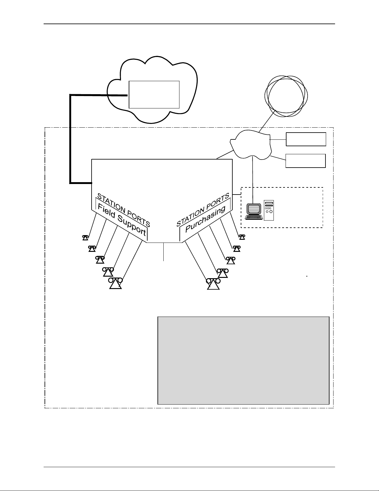
Spigglebrim’s Initial Situation
PSTN
Chapter 2: Sample System
Al, x5203
Bea, x5119
Cal, x5857
Dora, x5071
Local Telco
Central Office
Directory Number Range:
612-555-5xxx
PBX
No DID
[
support.
x5000
Operator
]
Internet
LAN
Phone/Computer
Administrator
Tom, x5001; tomq@spigb.com
Eve, x5176
Dan, x5890
Cindy, x 5549
Bob, x5528
Name Server
192.168.4.251
Mail Server
mail.spigb.com
Ed, x5486
Ann, x5411
Spigglebrim Vacuum Cleaner Co.
Office Facility
Needs:
1. Automated, flexible call routing.
2. Permanent phone numbers for outside callers,
despite internal changes.
3. Special handling for field-support calls.
Constraint:
PBX with no DID support.
Multi-Tech Systems, Inc. CF220 CallFinder User Guide 9
Page 10
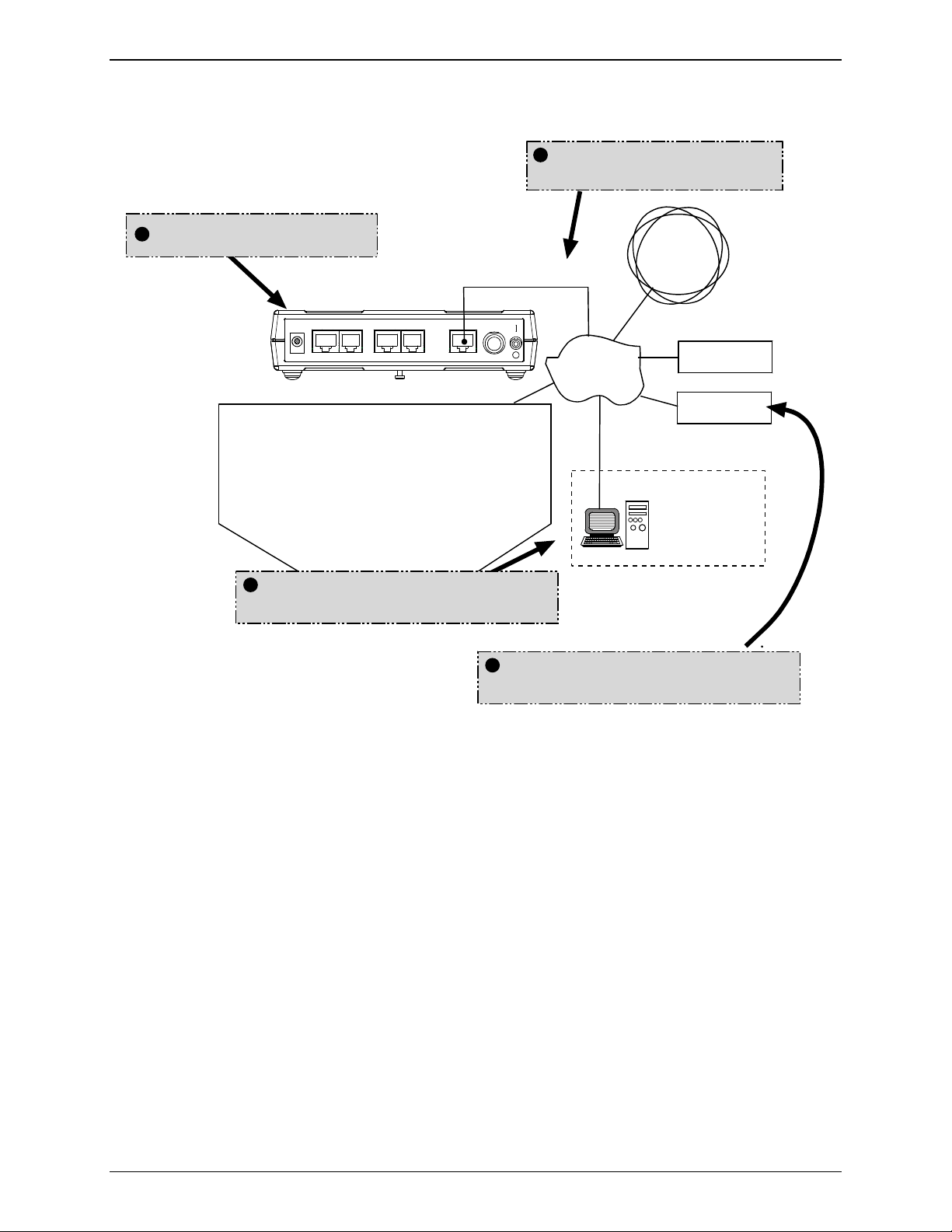
Step 1 Practical: Add CallFinder and connect to network.
CallFinder connects to
Ethernet LAN.
CallFinder is added.
Chapter 2: Sample System
Internet
Power
48Vdc
Channel 2
FXS/FXO DID
Channel 1
FXS/FXO DID 10/100
Ethernet
Power
5Vdc
LAN
Name Server
192.168.4.251
Mail Server
mail.spigb.com
PBX
No DID
[
support.
CallFinder’s built-in software
is accessed via web browser.
]
Phone/Computer
Administrator
CallFinder ties in with other
servers on the network.
Multi-Tech Systems, Inc. CF220 CallFinder User Guide 10
Page 11
Chapter 2: Sample System
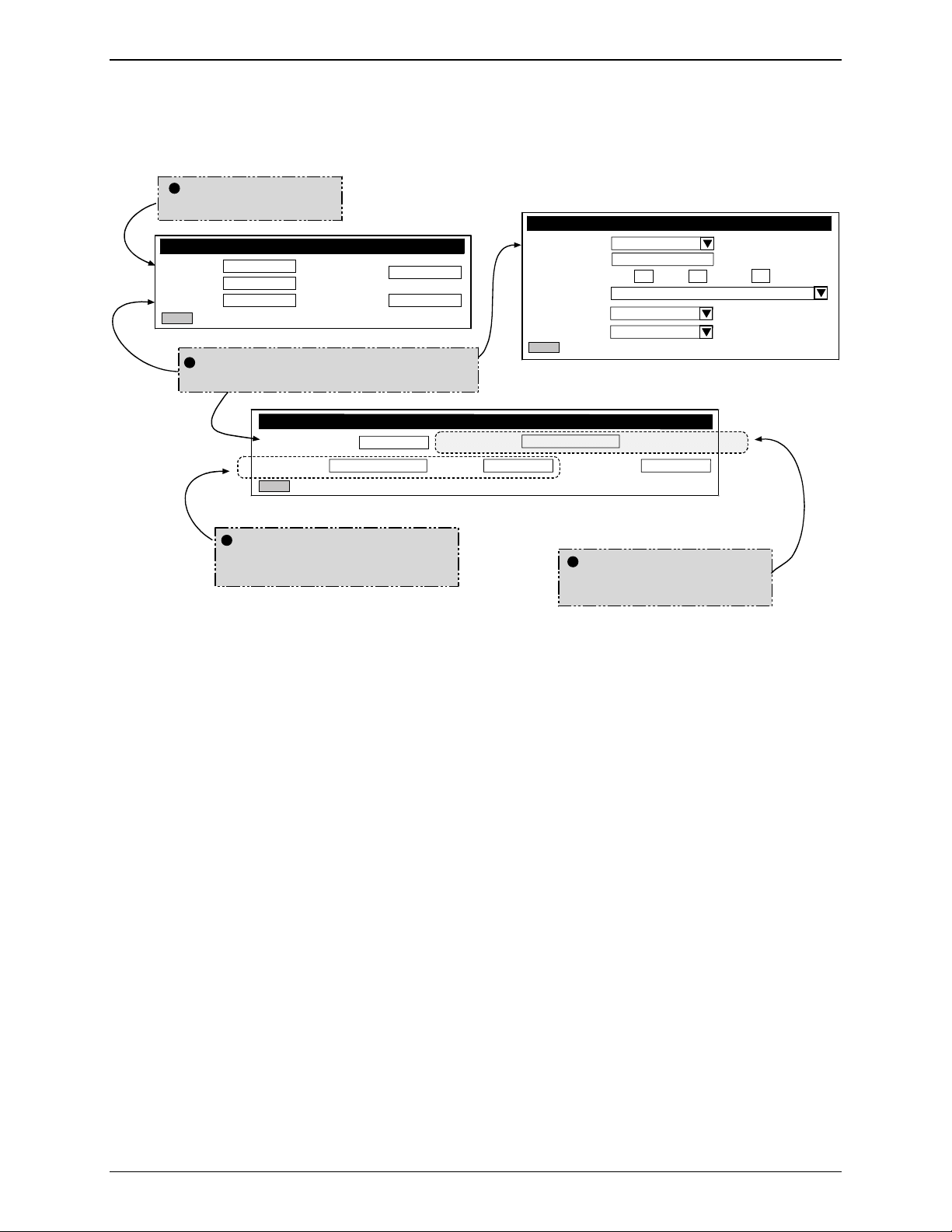
Step 1 Technical: Enter addresses of network servers in CF software.
Once assigned an IP address on the network, the CallFinder’s software (configured via web browser) can
link it to other servers on the network.
CallFinder gets own
IP address.
Administration: Time Configuration
Administration: IP Configuration
IP Address
Subnet Mask
Name Server
update
192.168.4.89
255.255.255.0
192.168.4.251
Default Gateway
Secondary
Name Server
CallFinder links to Name Server,
Mail Server & (Internet) Time Server.
SMTP Server Address mail.spigb.com
Server User ID
update
Time Ser ver
192.168.4.1
Add Time Server
Request Interval Days Hours Minutes0
Time Zone
Date Format
Time For mat
update
Administration: SMTP Configuration
Administrator Email
Password
tomq.spigb.com
Retype Password
time.nist.gov
24
(GMT-06:00) Central Time (US & Canada)
mm/dd/yyyy
12 hour
0
CallFinder may need User ID
and Password to accessMail
Server.
Logs of CallFinder calls
will be emailed to
administrator.
Multi-Tech Systems, Inc. CF220 CallFinder User Guide 11
Page 12
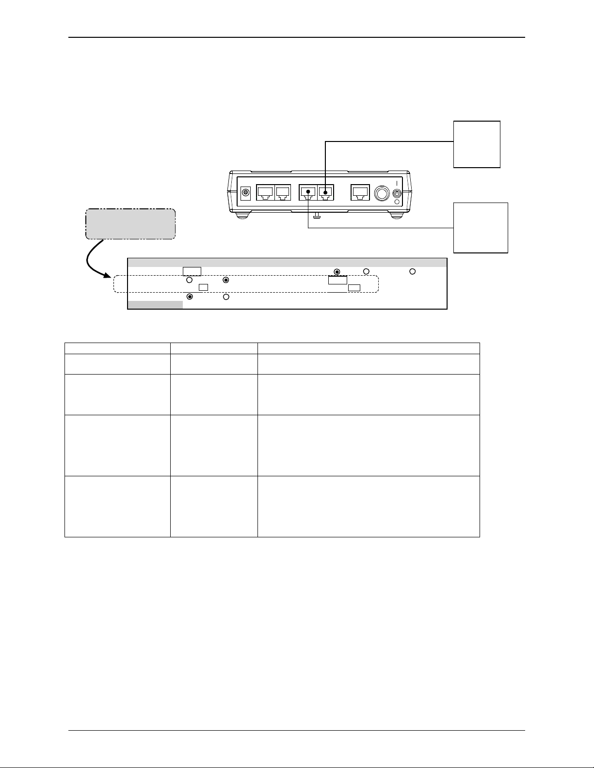
Step 2 Practical: Add DID lines and connect to CallFinder.
PSTN
Local Telco
Central Office
Two DID lines (10 directory
numbers each) are ordered
from the telco.
Dir. Numbers:
3101-3110
Chapter 2: Sample System
DID Lines
3111-3110
Power
48Vdc
Channel 2
FXS/FXO DID
Channel 1
FXS/FXO DID 10/100
Ethernet
Power
5Vdc
PBX
No DID
[
support.
]
Multi-Tech Systems, Inc. CF220 CallFinder User Guide 12
Page 13
Chapter 2: Sample System
Step 2 Technical: Enter operating parameters of DID lines.
Each DID line has 3 user-specified technical parameters. You set them in the CallFinder software.
Technical Parameters
of DID Line
Max DID Digits 4 DID Start
Extension Port
Receive Gain 100 Transmit Gain 100
Polarity
Update
Channel Configuration: Channel 2
FXS FXO
A B
Auto Attendant Delay 2
wink immediate delay dial
Telc o
DID
Outlet
CF
220
(Rear)
Power
48Vdc
Channel 2
FXS/FXO DID
Channel 1
FXS/FXO DID 10/100
Ethernet
Power
5Vdc
Te lc o
DID
Outlet
Max DID Digits 4 DID Start
Extension Port
Receive Gain 100 Transmit Gain 100
Polarity
Update
Channel Configuration: Channel 1
FXS FXO
A B
Auto Attendant Delay 0
wink immediate delay dial
Technical Parameters Related to DID Line
Parameter Value Comments
Max DID Digits 4 Number of digits received on DID line.
Polarity try A This is a trial-and-error setting. The DID line is a
twisted pair. Only when installed can you know
polarity. You determine the polarity by performance –
with wrong polarity, connections cannot be made.
DID Start ask telco Start mode varies with different implementations of
DID.
Multi-Tech Systems, Inc. CF220 CallFinder User Guide 13
Page 14
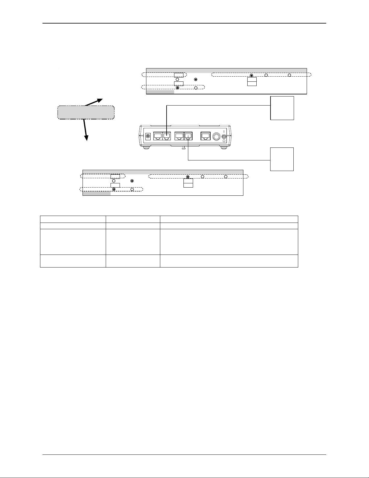
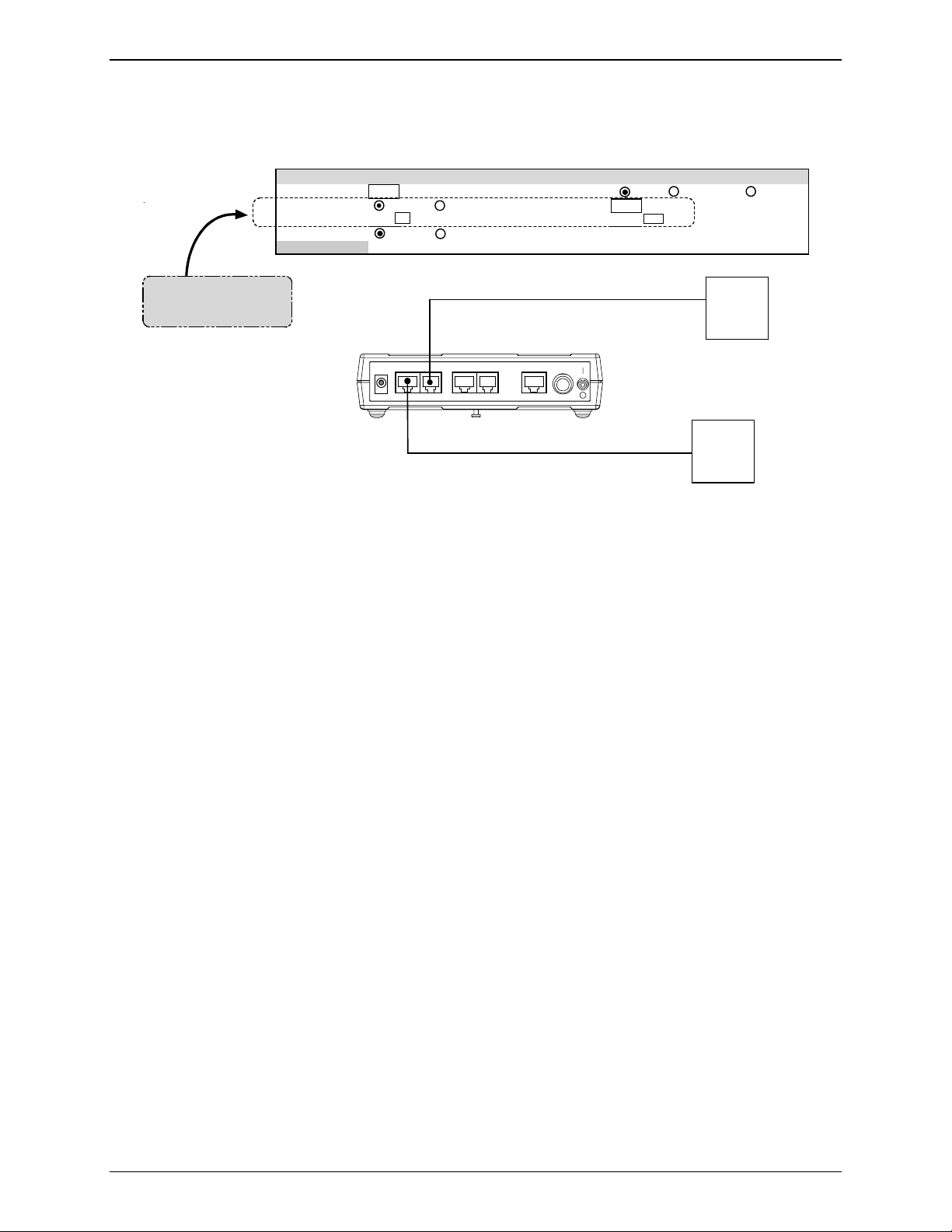
Chapter 2: Sample System
Step 3 Practical: Connect CallFinder port (FXO) to PBX for conventional DID
service (Purchasing Dept.).
DID Line
from telco
Dir. Numbers:
3111-3120
CallFinder FXS/FXO Port (CH1)
connects to a station port
on the PBX.
Power
CF220
(Rear)
48Vdc
Channel 2
FXS/FXO DID
Channel 1
FXS/FXO DID 10/100
Trunk
Port
Stati on
Port
PBX
No DID
support.
]
[
DID calls are treated like calls
originating at other PBX
extensions (”inside” calls).
Ethernet
Power
5Vdc
Eve, x5176
Dan, x5890
Cindy, x 5549
Bob, x5528
Ann, x5411
Multi-Tech Systems, Inc. CF220 CallFinder User Guide 14
Page 15
Chapter 2: Sample System
Step 3 Technical: Enter operating parameters of CallFinder channel (FXO)
Each of the CallFinder’s DID-channel modems has 4 user-specified parameters. You set them in the
CallFinder software.
Tel co
DID
Outlet
CF220
(Rear)
Power
48Vdc
Channel 2
FXS/FXO DID
Channel 1
FXS/FXO DID 10/100
Ethernet
Power
5Vdc
Technical Parameters
of CallFinder
DID-Channel Modem
Max DID Digits 4 DID Start
Extension Port
Extension Mic Gain
Receive Gain 100 Transmit Gain 100
Polarity
Update
Channel Configuration: Channel 1
FXS FXO
8
A B
Auto Attendant Delay 0
Extension Speaker Gain
wink immediate delay dial
30
Station
Technical Parameters Related to CallFinder’s Extension Port Line
Parameter Value Comments
Extension Port FXO Use FXO whenever CallFinder channel connects to
PBX station port.
Auto Attendant Delay 0
(in seconds)
Describes how long the CallFinder waits before
dialing. If set to 0, CallFinder calls as soon as PBX
dial tone is present. If no dial tone is present, the call
cannot be completed.
Extension Mic Gain 8 This describes the amplification of the sound input at
the local phone user’s mouthpiece microphone.
The default value is typically appropriate.
This is a very sensitive parameter and mis-adjustment
can render the channel inoperable.
Adjust carefully and only if needed.
Extension Speaker Gain 30 This describes the amplification of the sound output at
the local phone user’s earpiece speaker.
The default value is typically appropriate.
This is a very sensitive parameter and mis-adjustment
can render the channel inoperable.
Adjust carefully and only if needed.
PBX
Port
Multi-Tech Systems, Inc. CF220 CallFinder User Guide 15
Page 16
Chapter 2: Sample System
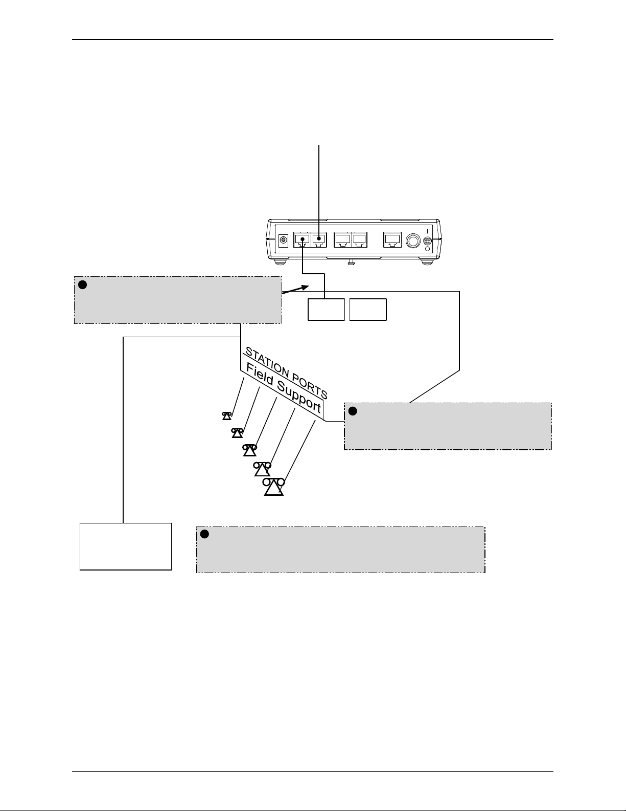
Step 4 Practical: Connect CallFinder port (FXS) to PBX for special DID service
(Field Support Dept.).
DID Line
from telco
Dir. Numbers:
3101-3110
CF220
(Rear)
CallFinder FXS/FXO Port (CH2)
connects to a trunk port
on the PBX.
Al, x5203
Bea, x5119
Cal, x5857
Dora, x5071
Ed, x5486
Power
48Vdc
Channel 2
FXS/FXO DID
Channel 1
FXS/FXO DID 10/100
Trunk
Port
PBX
No DID
[
support.
Power
Ethernet
5Vdc
Station
Port
]
DID calls are treated like calls
originating outside of the
PBX.
Billing
Because calls are handled as external calls,
more functionality can be added. Spigglebrim
Computer
Multi-Tech Systems, Inc. CF220 CallFinder User Guide 16
here is adding call-billing capability.
Page 17
Chapter 2: Sample System
Step 4 Technical: Enter operating parameters of CallFinder channel (FXS).
Technical Parameters
of CallFinder
DID-Channel Modem
Max DID Digits 4 DID Start
Channel Configuration: Channel 2
Extension Port
Extension Mic Gain
Receive Gain 100 Transmit Gain 100
Polarity
CF
220
(Rear)
FXS FXO
8
A B
Power
Channel 2
48Vdc
FXS/FXO DID
FXS/FXO DID 10/1 00
Auto Attendant Delay 0
Extension Speaker Gain
Channel 1
Ethernet
Power
5Vdc
wink immediate delay dial
30
Tel co
DID
Outlet
PBX
Station
Port
Multi-Tech Systems, Inc. CF220 CallFinder User Guide 17
Page 18

Step 5 Practical: Map PBX Extensions to DID Numbers
CF220
CallFinder
FXS
Port
FXO
Port
Chapter 2: Sample System
Billing
Computer
Al, x5203
Bea, x5119
Cal, x5857
Dora, x5071
Ed, x5486
Trunk
Port
Station
Port
PBX
x5000
Operator
CallFinder Administrator
Tom, x5001; tomq@spigb.com
Eve, x5176
Dan, x5890
Cindy, x 5549
Bob, x5528
Ann, x5411
Phone/Computer
Administrator
Multi-Tech Systems, Inc. CF220 CallFinder User Guide 18
Page 19
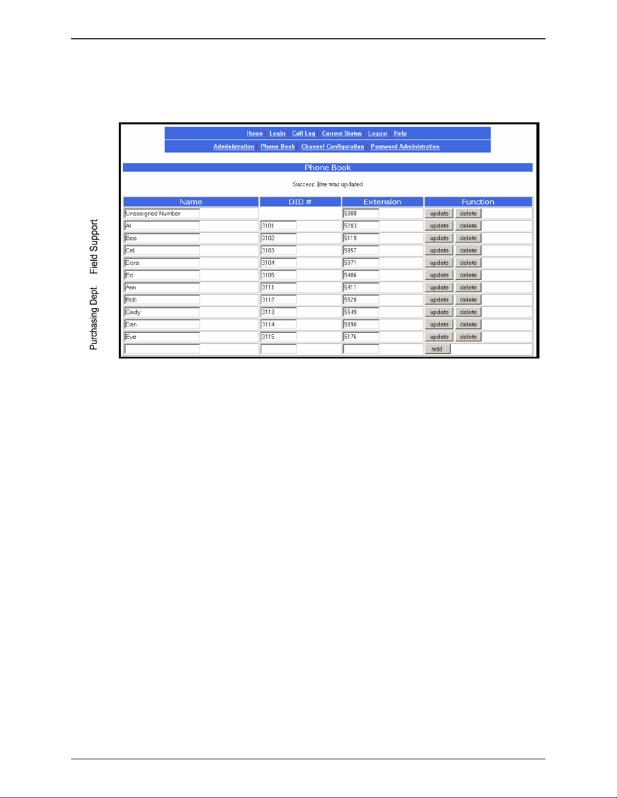
Step 5 Technical: Create CallFinder Phonebook.
Chapter 2: Sample System
This phonebook arrangement connects the five Field Support users to the CallFinder through one of the
PBX’s trunk ports (using DID numbers 3101 through 3105). This facilitates the use of a billing computer
for Field Support calls. The five Purchasing Department users are connected to the CallFinder through
one of the PBX’s station ports (using DID number 3111 through 3115). Because station ports are always
more numerous than trunk ports in PBXs, CallFinder channels are more likely to be connected to PBX
station ports than to PBX trunk ports in most systems.
If any outside caller dials 612-555-3106 or any other unused DID number will reach the receptionist
operator (x5000).
Multi-Tech Systems, Inc. CF220 CallFinder User Guide 19
Page 20
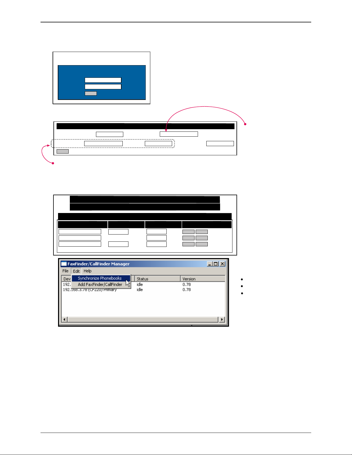
Step 6: Administering the CallFinder System
Multi-Tech CallFinder Call Router
Model CF220 - Version 1.0
For initial Login, use:
Username
Password
Login
admin
admin
Then change Login later.
Chapter 2: Sample System
Administration: SMTP Configuration
SMTP Server Address mail.spigb.com
Server User ID
update
Administrator Email
Password
Determine whether company’s email server
requires User-ID and Password for login
authentication. Give CF220 such a user-ID
and password if needed. This is different
than administrator’s Username & Password.
Home | Login | Call Log | Current Status | Logout | Help
Administration | Phone Book | Channel Config | Password Admin
Phone Book
Name
Administrator
Unassigned Number
Al
DID # Extension Function
3109
3101
5001
5000
3203
tomq.spigb.com
Retype Password
update
delete
update
delete
update delete
Designate an administrator
to receive call-logs via email.
Designate someone to take
calls made to unassigned
DID numbers.
Install FaxFinder/CallFinder
Manager software. It lets
you:
add more CallFinders to system
update firmware
synchronize phone books
among multiple CallFinders
in system
Multi-Tech Systems, Inc. CF220 CallFinder User Guide 20
Page 21

Chapter 2: Sample System
Conclusion
The CallFinder solved Spigglebrim’s problem. It added DID functionality to their existing PBX. Al in the
Field Support Department can now receive calls from the outside (dialed to 612-555-3101) while taking
both internal and external calls using his 5203 PBX extension number. Al’s Field Support calls are
handled as outside calls and they can be registered with a billing computer. Ann in the Purchasing
Department receives external calls (dialed to 612-555-3111) while taking both internal and external calls
using her 5411 PBX extension number. If either Al or Ann go on vacation, their incoming DID lines can
be re-directed in the CallFinder to another employee who knows their specialties. Spigglebrim Vacuum
Cleaners will be humming along for years to come.
Multi-Tech Systems, Inc. CF220 CallFinder User Guide 21
Page 22

Chapter 3: CallFinder Server Installation
Chapter 3 – CallFinder Server
Installation
This chapter shows you how to set up your Multi-Tech Model CF220 CallFinder.
The setup process entails cabling the CF220 unit and configuring the CallFinder software. The CallFinder
software resides on the CallFinder unit and does not need to be installed.
Prerequisite: Ordering the DID Line
To use the CallFinder system, you will need one or two DID (Direct Inward Dial) lines in your facility. You
must order the DID line(s) from your local telephone operating company (telco). A DID line allows one
phone line to be associated with multiple directory numbers. However, only one call can occur on this line
at any given time.
DID lines are sold in groups. For example, a telco in New York City might offer a DID line with a set of 20
directory numbers in the range of 212-555-4101 through 212-555-4120.
When ordering your DID line, ask the telco representative for these details about the DID service. These
details will be important when setting up your CF220 DID Adapter.
Parameter Value Required by
Telco
Number of digits used
to designate the DID extension
(usually 3, 4, 6, or 7)
Type of “DID Start” used
(wink, immediate, or delay dial)
You will need this information to configure your CallFinder (see step 8 on page 25).
We Supply
• A CF220 CallFinder with factory-installed software
• Two power supplies – one 5Vdc and one 48Vdc
• Two common telephone cables (RJ11 at both ends)
• Two DID telephone cables (RJ11 at one end; RJ12 at other end)
• A utility software program for updating CallFinder firmware
• This printed Quick Start Guide
Multi-Tech Systems, Inc. CF220 CallFinder User Guide 22
Page 23

Chapter 3: CallFinder Server Installation
You Supply
• Two nearby AC power outlets
• Two nearby connections to a PBX
• A connection to your Ethernet LAN
• One or two nearby analog DID trunk lines each with a block of associated DID telephone numbers
• A PC with Ethernet connection and web browser from which to configure the CallFinder unit. (Windows
or Linux can be used to access the CallFinder software. Windows NT, Windows 2000, or Windows XP
are required to access the FaxFinder/CallFinder Manager software.)
Installation, Part A: Connecting the CallFinder to Power
Outlets, Phone Lines, and Ethernet
Summary: Place the CallFinder in a convenient location, and then connect it to your AC power outlets
and Ethernet. Before connecting the extension lines, you need to know whether the CallFinder's ports will
function as FXO or FXS. The CallFinder’s default extension interface setting is FXO to prevent damage
from a mistaken connection. Be aware that an incorrect connection could damage the CallFinder unit or
the PBX. Do not connect FXS to FXS.
1. Connect CallFinder 5Vdc Power Supply to AC Outlet
Make sure the power switch is OFF. Plug the DC power transformer for the 5 Vdc power supply into a
power outlet or power strip. Plug the other end into the “Power 5Vdc” jack on your CallFinder. The DC
power transformer is included with your CallFinder.
Caution: Use only the 5 Vdc power transformer supplied with the CallFinder. Use of any other
transformer voids the warranty and can damage the CallFinder. The CallFinder’s 5Vdc
and 48 Vdc power supplies have different connector types to prevent mix-ups.
2. Connect CallFinder 48Vdc Power Supply to AC Outlet
Make sure the power switch is OFF. Plug the DC power transformer for the 48 Vdc power supply into a
power outlet or power strip. Plug the other end into the “Power 48 Vdc” jack on your CallFinder. The DC
power transformer is included with your CallFinder.
Caution: Use only the 48 Vdc power transformer supplied with the CallFinder. Use of any other
transformer voids the warranty and can damage the CallFinder. The CallFinder’s 5Vdc
and 48 Vdc power supplies have different connector types to prevent mix-ups.
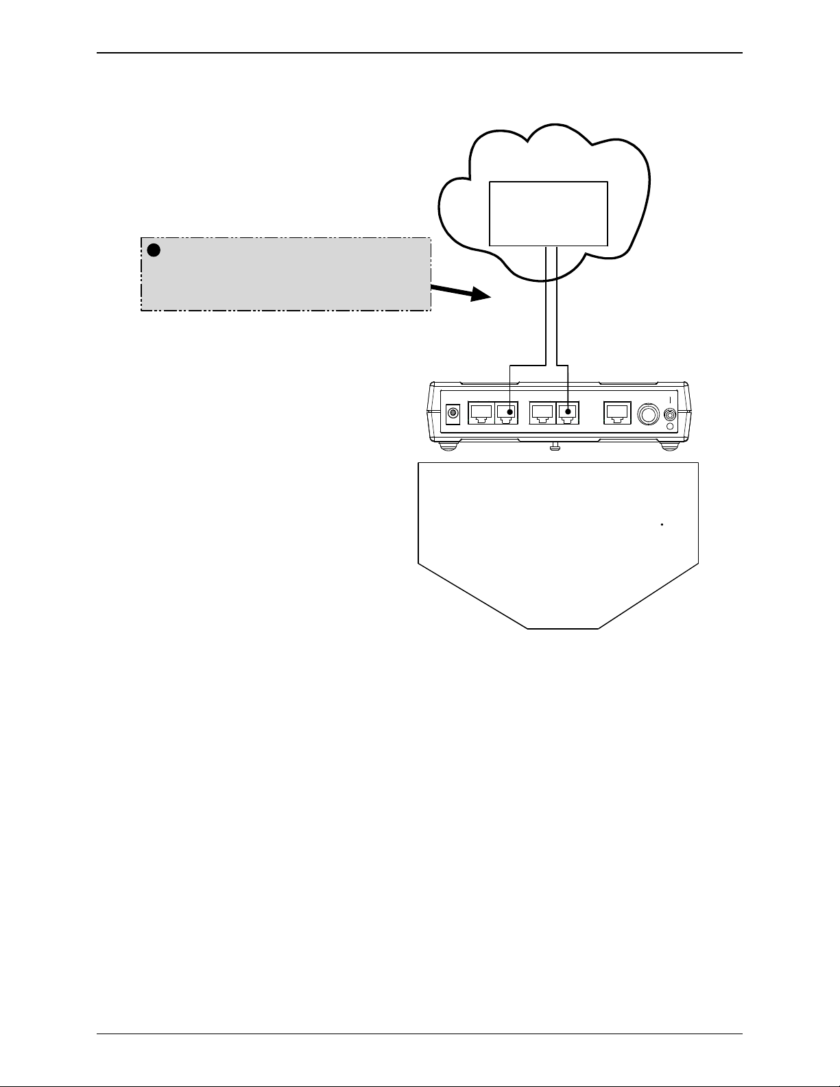
3. Identify CallFinder’s Extension Ports (FXS/FXO) for Later Hookup
Caution: You must wait until after the CallFinder software has been configured before connecting
the cables between the CallFinder’s Extension (FXS/FXO) Ports and the PBX.
Because the CallFinder and the PBX can both supply battery power, the cable
connections must be done properly. Otherwise equipment damage could occur.
Before making connections to the CallFinder Extension (FXS/FXO) channels, you must know the type of
PBX port to which each CallFinder port will be connected and set the “Extension Port” field in the
CallFinder
Multi-Tech Systems, Inc. CF220 CallFinder User Guide 23
Channel Configuration screen appropriately.
When connecting to a PBX Station Port,
set the CallFinder channel to FXO.
Page 24

Chapter 3: CallFinder Server Installation
When connecting to a PBX Trunk Port,
set the CallFinder channel to FXS.
When the Channel Configuration | Extension Port software field has been set properly for both
CallFinder channels, you can proceed to connect the cable between each of the CallFinder’s FXS/FXO
ports and the corresponding PBX port.
4. Connect CallFinder to DID Lines
Plug one end of the phone cable into the CallFinder’s Channel 1 DID jack and the other end into an
analog DID trunk line jack. The DID Line cable is included with your CallFinder.
Caution: The DID Line cable has an RJ11 connector on one end (this is the larger of the two
connectors; it goes to the telephone wall receptacle). The DID Line cable has an RJ12
connector on the other end (this is the smaller connector; it goes to the DID Port on the
CallFinder unit).
Never plug the DID connector into a standard POTS Line. This may damage the
CallFinder or the central office equipment. Use only an analog DID Line.
Repeat for the CallFinder’s Channel 2 DID port.
5. Connect CallFinder to Ethernet Network
Plug one end of your RJ45 ethernet cable into the CallFinder’s ethernet jack and the other end into your
network ethernet hub. This ethernet cable is not included with your CallFinder unit.
Note: Before connecting to the Ethernet Network, make sure that the network to which you
are connecting the CallFinder is not a 192.168.2.x subnet.
If it is a 192.168.2.x subnet, it will clash with the CallFinder because the CallFinder’s
default IP address is 192.168.2.1. To remedy such a situation, connect from the Admin
PC to the CallFinder using an RJ45 crossover cable until the CallFinder’s IP address
has been configured. Thereafter, connect the CallFinder into the network with an
ordinary RJ45 cable.
6. Do Power-On Test
Test your CallFinder by turning it on (an on-off switch is located on the back panel). When you apply
power, the CallFinder performs a diagnostic self-test. The Status indicator flashes when the test is
complete and the unit is ready. If this does not happen, check that the power switch is on, the power
supply is solidly connected, and the AC outlet is live.
Multi-Tech Systems, Inc. CF220 CallFinder User Guide 24
Page 25
Chapter 3: CallFinder Server Installation
Part B: Configuring the CallFinder Server
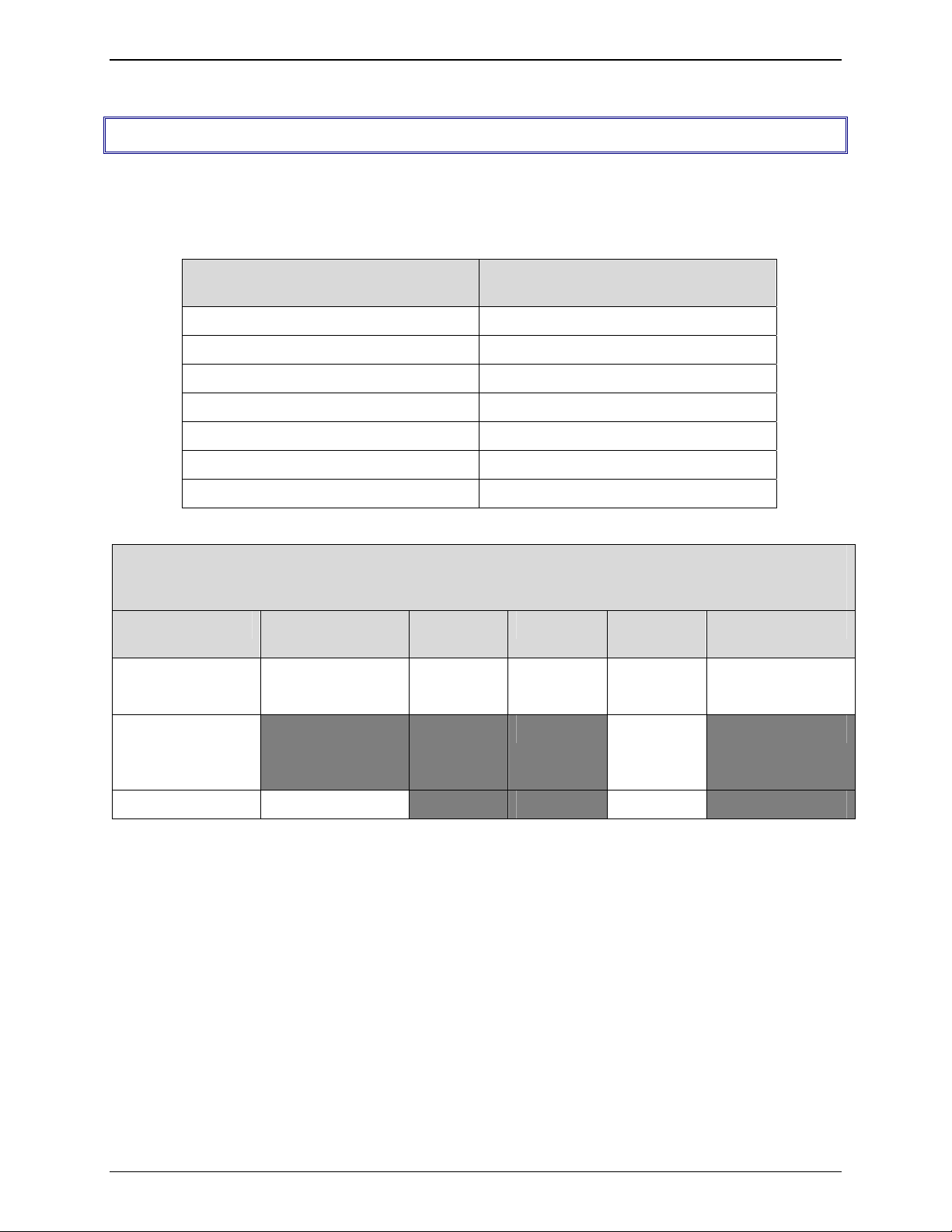
1. Collecting Configuration Data
The table below lists the information you will need to fill in on the various CallFinder Server screen.
Gathering this information in advance will expedite the CallFinder configuration process.
Server Parameters
Values for this CallFinder
(for Server Admin screen)
IP Address (of FaxFinder unit)
Subnet Mask
(Domain) Name Server
Secondary Name Server (optional)
Default Gateway
Time Server (typically time.nist.gov)
SMTP (Mail) Server Address
Administrative User Parameters
(for Server Phonebook & Configuration (SMTP) screens
and FFCF Manager’s Add FaxFinder screens)
Name User ID/
Username
Administrator
Email
Address
DID # PBX
Password
Extension
Unassigned
Number
Server ID
recipient
Multi-Tech Systems, Inc. CF220 CallFinder User Guide 25
Page 26

Chapter 3: CallFinder Server Installation
Ordinary User Parameters
(for CallFinder Phonebook)
Name DID Number PBX Extension
Multi-Tech Systems, Inc. CF220 CallFinder User Guide 26
Page 27

Chapter 3: CallFinder Server Installation
2. Setting Admin PC to Startup IP Address
a. Connect a pc to your network.
b. Set the pc IP address to 192.168.2.x subnet (using any address excluding 192.168.2.1).
Windows XP
a. From the Windows desktop,
right-click on “My Network Places,”
and select “Properties.”
b. In the Network Connection
screen, right-click on “Local Area
Connection.”
c. In the Local Area Connection
Properties screen, on the
“General” tab, scroll to the “Internet
Protocol (TCP/IP)” entry and select
it. Click “Properties.”
d. In the Internet Protocol
(TCP/IP) Properties screen, record
the existing IP address. Then reset
the IP address to 192.168.2.2.
Windows NT
a. From the Windows desktop, right-click on “Network Neighborhood,” and
select “Properties.”
b. In the Network screen, on the “Protocols” tab, select “TCP/IP Protocol” in
the list of Network Protocols. Click “Properties.”
c. In the Microsoft Internet Protocol (TCP/IP) Properties screen, record
the existing IP address. Then reset the IP address to 192.168.2.2.
Windows 2000
a. From the Windows desktop, rightclick on “My Network Places,” and
select “Properties.”
b. In the Network and Dialup
Connections screen, right-click on
“Local Area Connection” and select
“Properties.”
c. In the Local Area Connection
Properties screen, select the
“Internet Protocol (TCP/IP)” entry.
Click “Properties.”
d. In the Internet Protocol (TCP/IP)
Properties screen, record the
existing IP address. Then reset the
IP address to 192.168.2.2.
3. Logging In (I)
a. Bring up a Web browser on your PC. At the browser’s address line, type the default IP address of the
CallFinder (
b. The
Login screen will appear.
http://192.168.2.1) and then press Enter.
At this point you can be assured that the CallFinder is connected to the network.
Login screen does not appear, see item #1, “What if I can’t see the web page for my
If the
CallFinder?” in the
c. At the
d. Enter
e. Click the
Login screen, enter admin (all lower case) in the User Name field.
admin (all lower case) in the Password field.
Login button. The Web Management Home screen will appear. From this screen, you can
Troubleshooting section (page 79 ).
access all of the CallFinder software screens.
Multi-Tech Systems, Inc. CF220 CallFinder User Guide 27
Page 28

Chapter 3: CallFinder Server Installation
4. Setting CallFinder IP Addresses
a. In the CallFinder Administration screen, go to the IP Configuration fields.
Administration: IP Configuration
IP Addr ess
Subnet Mask
Name Server
upda te
b. Fill in the IP information that applies to your CF220 CallFinder Server unit. The fields for “IP Address,”
“Subnet Mask,” “Default Gateway” and “Name Server” are required. A “Secondary Name Server”
may be considered optional.
192.168.4.89
255.255.255.0
192.168.11.251
Default Gateway
Secondary
Name Server
192.168.4 .1
c. Click
Update. The CallFinder will adopt the new IP address 5 seconds after the Update command is
invoked.
5. Resetting Admin PC to Its Regular IP Address
In step #2 above, you recorded the original IP address of the administrator’s PC and then reset it to the IP
address required to allow communication with the CallFinder unit. You must now set the IP address of
the administrator’s PC to a value that allows you to reach CallFinder at its new IP address.
6. Logging In (II)
Having reset the IP address of the administrator’s PC, you must log into the CallFinder software again.
Go to the Login screen, enter admin as User Name and admin as Password.
Note: If you changed the IP address of your PC to accommodate the CallFinder, a
slight complication will occur when you try to login to the CallFinder at this point.
At the Login screen, after entering your username and password, you will be
prompted to log another user out. Select “Yes.” (Clicking
logged-in status you had earlier when your PC was at its previous IP address.)
Yes cancels the
Multi-Tech Systems, Inc. CF220 CallFinder User Guide 28
Page 29
7. Setting Administrative Functions
Go to the CallFinder Phone Book screen.
Chapter 3: CallFinder Server Installation
a. Administrator Row: Specifying DID# and PBX Extension
i. In the first row (marked Administrator) of the Phone Book screen, enter the DID number
and PBX extension of the CallFinder administrator. The first row is
who performs the ‘administrator’ function. Even if the
changed (which is permissible) it still pertains to the administrator function (which includes
receiving call-log emails).
ii. Click on
b. “Unassigned Number” Row: Specifying PBX Extension
i. In the second row (marked “Unassigned Number” by default) of the Phone Book screen,
enter the name and PBX Extension of the party that you want to receive calls made to
unassigned DID numbers (if there are any). The second row is
receives calls made to unassigned DID numbers. Even if the
row is changed (which is permissible) it still pertains to the function of receiving calls made
to unassigned numbers. All incoming calls made to activated DID numbers for which no
PBX extension has been assigned will go to the party listed in the second row. (Calls
involving corrupted DID numbers will also go to the Unassigned Number PBX extension.)
Typically an operator (or administrator) might handle such calls. However, any name can
be entered in this second row.
ii. Click on
appear above the Phone Book list.
Update in the first row. The Login screen will re-appear. Log in again.
Update in the second row. The message “Success: [name] was updated” will
Name field of this first row is
always for the party
always for the party who
Name field of this second
Multi-Tech Systems, Inc. CF220 CallFinder User Guide 29
Page 30

Chapter 3: CallFinder Server Installation
8. Setting Up the Mail Server
The CallFinder uses a mail server to send, by email, call log reports to the administrator. An email is also
sent to the administrator each time the CallFinder is powered up. In all cases, you must specify the
address of the mail server and the email address of the administrator. Some email servers require
authentication before allowing the CallFinder access. In these cases, the CallFinder unit must be
assigned a Server User Name and a password. If the mail server does not require authentication, the
bottom row of SMTP Configuration fields (“Server User ID,” “Password,” and “Retype Password”) must
be left blank.
a. In the CallFinder Administration screen, go to the SMTP Configuration fields.
b. Fill in the network IP address or domain name of your mail server.
c. Enter the email address of the administrator (the party that you want to receive call log reports).
d. At this point the Administrator should receive an email from your CallFinder saying that the mail
server address has been updated.
Email Server Authentication Parameters. If your email server requires authentication in order to
e.
give the CallFinder access, fill in the lower three fields (
Password
ID and Password, then you
However, if your network email program
messages, you
blank, then the error “SMTP Authentication Error” will appear on the
“Email Status” field. If authentication is not required and these fields
also occur.
Administration: SMTP Configuration screen accordingly.
). If you can enter the network email program and send messages without entering a User
must leave these fields blank.
does require a User ID and Password in order to send email
must fill in these three fields. If authentication is required and these fields are left
You must know how your email server works in this regard and complete the
Server User ID, Password, Retype
Current Status screen in the
are filled in, then an error will
f. If you do not receive an email saying that the mail server address has been updated, see item #2
“What if I don’t get an email when I set the mail server address?” in the Troubleshooting section of
this manual (page 79).
Multi-Tech Systems, Inc. CF220 CallFinder User Guide 30
Page 31

Chapter 3: CallFinder Server Installation
9. Configuring the CallFinder’s Channels
The CallFinder’s channels direct inbound calls to their proper destinations.
a. In the CallFinder software, go to the Channel Configuration screen.
b. Under
Channel Configuration: Channel 1, enter the values that match the characteristics of your
DID phone line in the fields provided. Three parameters relate to the DID line coming into the
CallFinder channel. Four parameters relate to the PBX extension line to which the CallFinder channel
connects.
DID Line Parameters
Consult the telco supplying the DID line about these parameters. See the section “Prerequisite:
Ordering the DID Lines” on page 6.
Max DID Digits: the number of digits the CallFinder will receive from the telco central office on
the DID line.
DID Start: wink, immediate, or delay dial.
Polarity: This refers to the DID battery polarity. This parameter must be set on a trial-and-error
basis.
Signs of incorrect polarity:
(1) outside party originating call to DID number gets immediate busy signal after dialing;
(2) line suddenly disconnects just when call should go through.
PBX Extension Line Parameters
Extension Port
: default = FXO (prevents damage from wrongly applied battery
and ring voltages)
Set as FXO when the CallFinder is to be connected to a PBX station port (a port that is
normally connected to a normal analog telephone).
Set as FXS when the CallFinder is to be connected to a PBX trunk port (a port that would
normally be connected to an ordinary POTS phone line from the telco central office.
Auto Attendant Delay
: The Auto Attendant Delay value, x, determines how long the
CallFinder will pause before dialing on the PBX.
If the CallFinder channel is configured as an FXS port it will ring the PBX and wait x seconds
before dialing the proper extension after the PBX seizes the line.
Set x to be 1 or greater.
If the CallFinder channel is configured as an FXO port, x is the length of time that the
CallFinder will wait before dialing after the CallFinder itself has seized the line from the
PBX.
If set x to 0, the CallFinder must detect dial tone from the PBX before dialing. (The setting
0 can be used only if the PBX presents dial tone to the CallFinder.)
of
Multi-Tech Systems, Inc. CF220 CallFinder User Guide 31
Page 32
Chapter 3: CallFinder Server Installation
Extension Mic Gain: This value adjusts the volume of the phone’s microphone. Default = 8.
Increase value if outgoing audio signal is constant but low.
Decrease value if outgoing audio signal intermittently cuts out or is clipped.
This parameter is sensitive and important to system performance.
Extension Speaker Gain: This value adjusts the volume of the phone’s speaker. Default =
30.
Increase value if outgoing audio signal is constant but low.
Decrease value if outgoing audio signal intermittently cuts out or is clipped.
This parameter is sensitive and important to system performance.
c. Click Update.
d. Click on Current Status. Watch the Current Status: Channel-1/Channel-2 portion of the screen.
The “State” of each DID Modem should be “Waiting for Ring.”
10. Connecting CallFinder to PBX
Now that the Extension Ports have been configured (as FXS or FXO) you can connect the cables
between the CallFinder’s Channel 1 and Channel 2 connectors and the appropriate PBX port.
Remember:
(a) to connect a CallFinder channel to a PBX trunk port, the channel must be set to FXS;
(b) to connect a CallFinder channel to a PBX station port, the channel must be set to FXO.
11. Testing the Channel with a Call
a. From another phone (either from from another PBX extension or from an ordinary POTS phone
independent of the PBX), call one of the DID phone numbers that is active in the system. Dial the
DID phone number as you would from an outside line (it will not work to dial the number as if it were
an ordinary 3- or 4-digit extension of the PBX).
b. In the
Current Status: DID Modem screen, the "State" field should change to "Waiting for Connect"
(briefly) and then to “Connected” (for the duration of the call) indicating that the voice connection to
the assigned PBX extension has been made. (The
Current Status screen is updated automatically
each time you open the screen and every two minutes or so thereafter.)
c. If you observe both the "Connected" state and verify the presence of voice, then the CallFinder's
Channel has been configured properly.
If either of these is absent, see item #3 “What if the CallFinder channel doesn’t answer a call on the
DID line?” in the
Troubleshooting section of this manual (page 81).
Multi-Tech Systems, Inc. CF220 CallFinder User Guide 32
Page 33

Chapter 3: CallFinder Server Installation
12. Changing Administrator’s Password for CallFinder SW
a. In the Password Administration screen, enter a new User ID and Password for the CallFinder
Administrator (something other than “admin” and “admin”). This User ID and password are used to
give the administrator access to the CallFinder’s built-in software. Re-enter the password in the
“Confirm Password” field. Passwords can be as short as 1 character, as long as 40 characters, and
are case-sensitive.
b. Click Update for this row. The Login screen will appear.
13. Assigning DID Numbers to PBX Users (Extensions)
a. In the Phone Book screen just below the entries for the CallFinder administrator, make phonebook
entries for the other persons in your office to whom DID numbers have been assigned.
For each such DID user, enter the name, DID number (the digits that the DID line will be sending to
the CallFinder to reach this user), and PBX extension (the number that the CallFinder must dial on
the PBX to reach the user) in the appropriate fields.
b. Click on
above the Phone Book list.
Add for each row completed. The message “Success: [name] was updated” will appear
Multi-Tech Systems, Inc. CF220 CallFinder User Guide 33
Page 34

Chapter 4: CallFinder Software Screens
Chapter 4 – CallFinder Software
Screens
In this chapter, we present the screens of the CallFinder software. We describe each field in each screen
and some of the command buttons. (We do not describe command buttons that have functions that would
be readily understood by users of Windows software. Examples of such self-evident functions include
buttons like “OK,” “Cancel,” “Next,” etc.)
Home Screen
The CallFinder Home screen offers access to all other CallFinder software screens.
Multi-Tech Systems, Inc. CF220 CallFinder User Guide 34
Page 35

Chapter 4: CallFinder Software Screens
Login Screen
The CallFinder Server Login screen is the primary security device for the Server software.
The CallFinder has a default setting that allows use of “admin” as both the User Name and the Password
at initial startup. After you have begun configuring your CallFinder unit, you should change the password
in the Password Administration screen described later in this chapter.
If you try to log in while another party with Administrator is logged in, a confirmation screen lets you
decide whether or not to log in in place of that party. Remember: when you log in, that other party will be
logged out. (Only one party can be logged in at at time.)
Multi-Tech Systems, Inc. CF220 CallFinder User Guide 35
Page 36
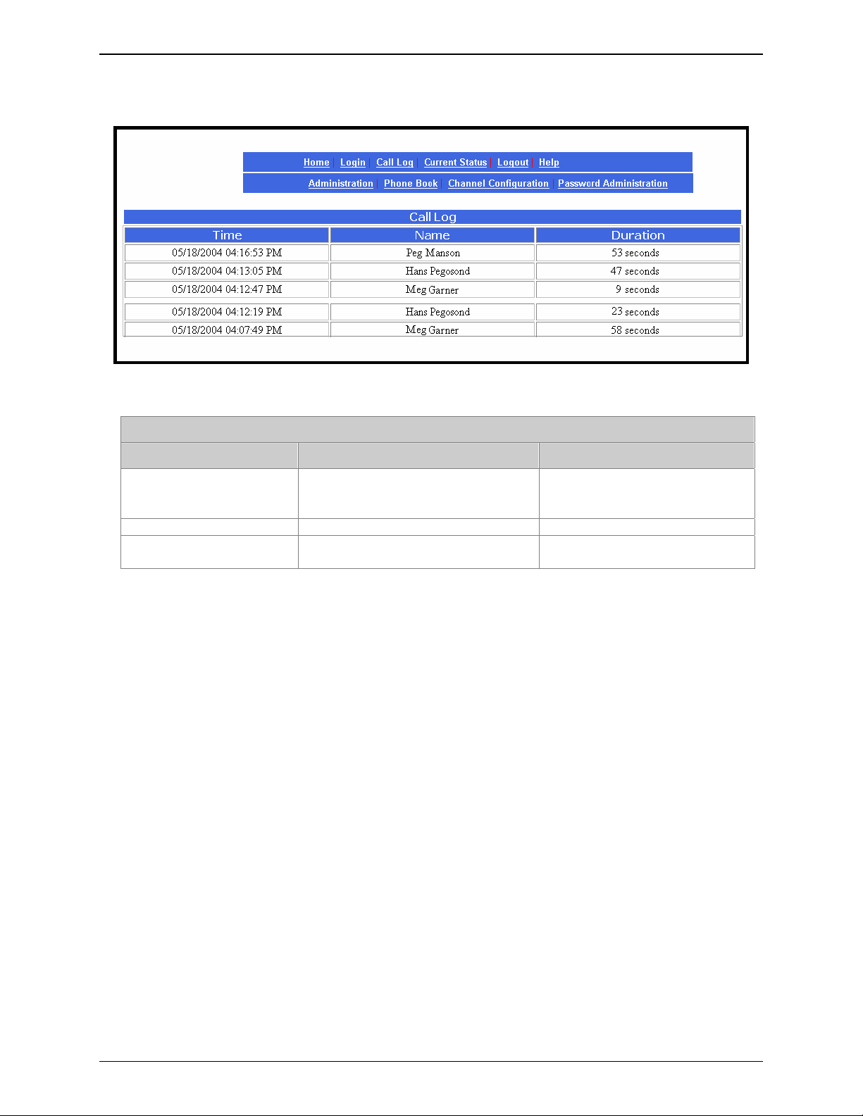
Call Log Screen
Chapter 4: CallFinder Software Screens
Call Log Screen Field Definitions
Column Values Description
Time mm/dd/yyyy + hh/mm/ss + am/pm
dd/mm/yyyy + hh/mm/ss + am/pm
yyyy/mm/dd + hh/mm/ss + am/pm
Name alphanumeric Party receiving call.
Duration mmm minutes
ss seconds
Date and time at which call was
received.
How long the call lasted.
Multi-Tech Systems, Inc. CF220 CallFinder User Guide 36
Page 37

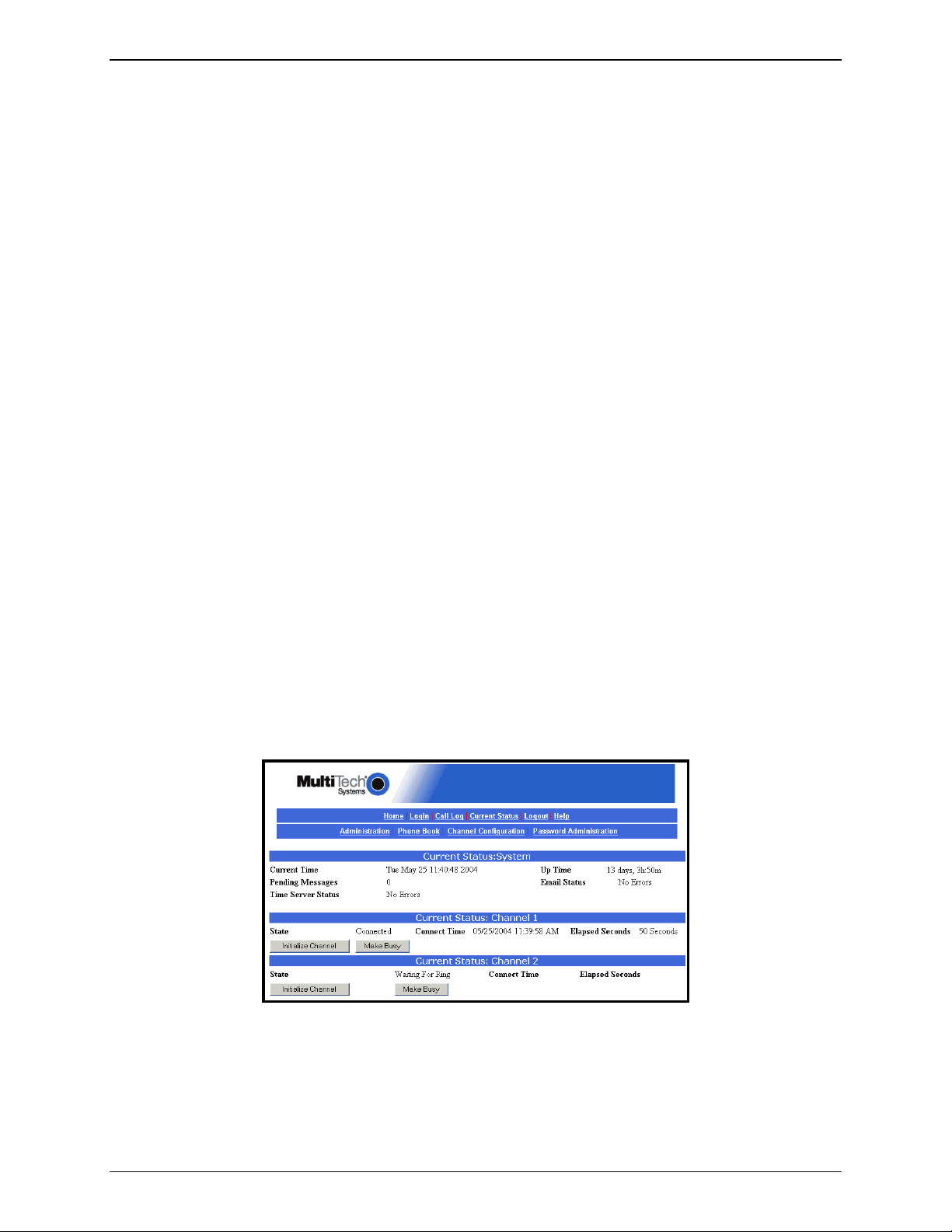
Current Status Screen
Chapter 4: CallFinder Software Screens
Current Status Screen Field Definitions
Field Name Values Description
System fields group
Current Time weekday, mo, dd
hh:mm:ss yyyy
Pending Msgs numeric Emails that have arrived in the CallFinder unit
Time Server Status Initializing,
No Errors,
SNTP Error: type
The present time of day.
that have not yet been conveyed to clients.
These include administrative emails of several
kinds: call log messages, debug log messages,
call error messages, mail server change
notification message (relating to the “SMTP
Server Address” field of Administration screen),
reboot message indicating that the CallFinder is
online.
The CallFinder synchronizes its call time stamps
to an Internet source, usually a government
standards site. It will attempt contact with the
standards web site 5 times in 20 seconds. If
contact fails, it will try 5 times again 5 minutes
later. If contact succeeds, the FaxFinder will
update its stamping time periodically per an
interval set in the Administration screen.
Multi-Tech Systems, Inc. CF220 CallFinder User Guide 37
Page 38

Chapter 4: CallFinder Software Screens
Current Status Screen Field Definitions (cont’d)
Field Name Values Description
System fields group
Up Time x days yy hours:
zz minutes
Email Status No Errors,
Bad MailServer
Address,
Mail Server
Connect Failed,
SMTP Invalid
Response, SMTP
Client Timeout
Channel 1 & 2 fields group
State Waiting for Ring,
Initializing Modem,
Waiting for
Connect,
Connected
Busied Out
Connect Time mm/dd/yyyy,
hh:mm:ss
Elapsed Seconds numeric The duration of the current call in seconds.
Initialize Channel (button) Initializes the modem, clearing a busied-out
Make Busy (button)
Operation time since last reboot.
Indicates whether or not the CallFinder can
communicate properly with an email server.
Indicates the current operating condition of the
CallFinder’s channel (Channel 1 or 2).
For the current call, the date and time at which
the connection began.
state.
Imposes a busied state on the channel.
Logout Option
When you click on Logout in the CallFinder Home screen, you will be logged out of the CallFinder
software. The Login screen will appear to allow access to re-enter the program.
Help Screen
Online Help has not yet been implemented.
Multi-Tech Systems, Inc. CF220 CallFinder User Guide 38
Page 39

Administration Screen
Chapter 4: CallFinder Software Screens
Administration Screen Field Definitions
Field Name Values Description
IP Configuration Fields
IP Address n.n.n.n
for n = 0-255
Subnet Mask n.n.n.n
for n = 0-255
Name Server n.n.n.n
for n = 0-255
Default Gateway Name n.n.n.n
for n = 0-255
Secondary Name Server n.n.n.n
for n = 0-255
Update (button) Click on this button to make changes to IP
The IP address of the CallFinder.
This subnet mask is the subnet for the network to
which the CallFinder is connected. A subnet
mask is used in conjunction with the IP address
to determine if a data destination is on the same
immediate network or not (in the case of
networks made of hubs and ethernet cards). The
default value, often used, is 255.255.255.0.
The IP address of a local DNS server.
Address used to route data out of the immediate
network.
The IP address of a backup DNS server, which is
typically at a separate location.
Configuration fields take effect.
Multi-Tech Systems, Inc. CF220 CallFinder User Guide 39
Page 40

Chapter 4: CallFinder Software Screens
Administration Screen Field Definitions
Field Name Values Description
SMTP Configuration Fields
SMTP Server Address n.n.n.n
for n = 0-255
Server User ID alphanumeric Identifier used by CallFinder when interfacing
Domain name or IP address for mail server
(SMTP must be supported on mail server).
with mail server. CallFinder uses mail server to
send call reports to administrator. Some email
servers require authentication when accessed for
this purpose. To satisfy this authentication
requirement (where needed), a User ID must be
specified for the CallFinder unit. Leave this field
blank if authentication is not needed.
Administrator Email alphanumeric Email address to which call log reports will be
sent. An email is also sent to the administrator
each time the CallFinder is powered up and
when mail configuration settings are updated.
Password alphanumeric Password used by CallFinder server unit when
accessing mail server. Leave this field blank if
authentication is not needed.
Retype Password alphanumeric Reiteration of above password.
Update (button) Click on this button to make changes to SMTP
Configuration take effect. Updating triggers the
sending of an email to the administrator.
Time Configuration Fields
Time Server URL Location of time-tracking computer that supports
SNTP. This server is the functional substitute for
a real-time clock in the CallFinder unit. Clock
sources can be found on the Internet. In the
absence of an Internet connection, a time source
within the CallFinder network must be
established. The clock is used for call logging.
URL Used to add a user-supplied time server.
Add Time Server
alphanumeric Indicates the time zone in which the CallFinder
Time Zone
unit is located.
Multi-Tech Systems, Inc. CF220 CallFinder User Guide 40
Page 41

Administration Screen Field Definitions (continued)
Field Name Values Description
Time Configuration Fields (continued)
Chapter 4: CallFinder Software Screens
Request Interval
the CallFinder will update its clock from the Time
Server.
Update (button) Click on this button to make changes to Time
Configuration settings take effect.
This value (to be set by user) indicates how often
Date Format mm/dd/yyyy, OR
dd/mm/yyyy, OR
yyyy/mm/dd
The date can be set to one of three orders,
where
month, and
mm is the month, dd is the day of the
yyyy is the year.
Time Format 12-hour or 24-hour Indicates whether time is presented in a 12-hour
scheme with an am/pm designation or in a 24hour scheme.
Multi-Tech Systems, Inc. CF220 CallFinder User Guide 41
Page 42

Chapter 4: CallFinder Software Screens
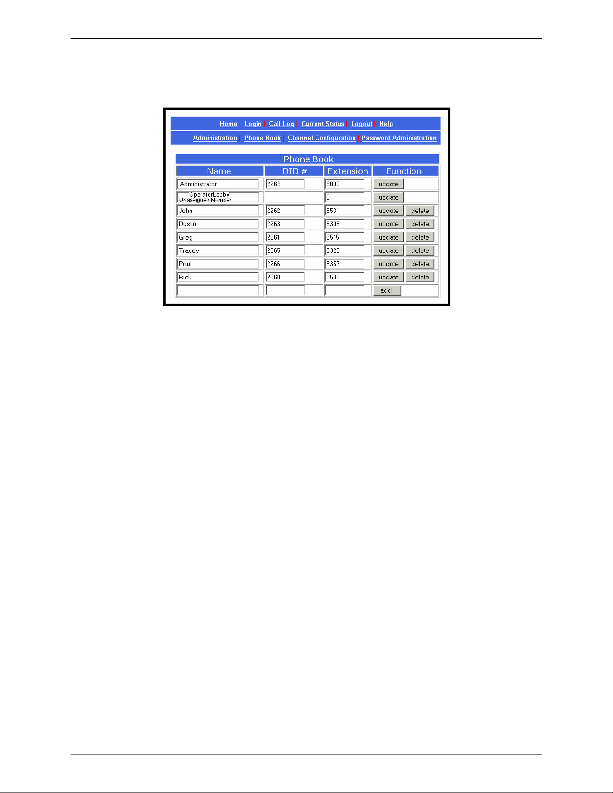
Phone Book Screen
The Phone Book screen maps the PBX extension phone numbers of clients to their respective external
DID numbers.
Phone Book Screen Field Definitions
Field Name Values Description
Name column alphanumeric For each client entry, this column shows the
DID Number column alphanumeric The DID number assigned to the user named in
Extension column numeric The PBX extension to which calls to the listed
Function column Buttons for
Update, Delete,
and Add functions
client’s name.
this row. This is the phone number at which this
user can be reached by direct dialing because of
the CallFinder’s inbound routing functionality.
Typically, these DID numbers are three-digit or
four-digit numbers. The quantity of these DID
phone numbers available from a single DID line
depends on the telco. Telcos commonly offer
DID service by alloting twenty DID numbers to a
single DID phone line. However, other line
quantities may be offered.
DID number will be directed.
For each user entry, this column presents
functions that can be invoked upon the entry.
Multi-Tech Systems, Inc. CF220 CallFinder User Guide 42
Page 43

Chapter 4: CallFinder Software Screens
Phone Book Screen Field Definitions (cont’d)
Field Name Values Description
First row alphanumeric Administrator row.
NOTE: This first row can be renamed as desired.
However, its function will always remain the
same: it is the party who serves as administrator
for the CallFinder system. Do not enter the
Name and DID number of an ordinary user in this
field.
Second row
(with default label
“Unassigned Number”)
alphanumeric Ideally, a PBX extension is assigned to every
available DID number. If, however, there are DID
phone numbers to which no PBX extension has
been assigned, calls to these unassigned
numbers will go to the destination specified in
this field. (Calls involving corrupted DID numbers
also go to the party handling the Unassigned
Number function.) Such calls might reasonably
go either to the extension of a
receptionist/switchboard-operator or to an
extension that plays a recorded message.
NOTE: This second row can be renamed as
desired. However, its function will always remain
the same: it is the destination for calls to DID
numbers to which no PBX extension has been
assigned. Do not enter the Name and DID
number of an ordinary user in this field.
Multi-Tech Systems, Inc. CF220 CallFinder User Guide 43
Page 44

Chapter 4: CallFinder Software Screens
Channel Configuration Screen
“Channel Configuration: Channel 1 & Channel 2” Screen Field Definitions
Field Name Values Description
Max DID Digits 1-7
Extension Port FXS or FXO Denotes the interface type of the port (Channel 1
Extension Mic Gain 0 to 255 The degree of amplification that the CallFinder
Polarity A or B Orientation of DID battery voltage. Polarity of the
DID Start wink, immediate,
delay dial
The number of digits that the telco supplies to the
DID line when an incoming call is received.
Default = 4.
or Channel 2). Each CallFinder port can be set
up either as an FXS port or as an FXO port. If a
port is configured as FXS, it would commonly be
connected to a PBX trunk line. If a port is
configured as FXO, it would commonly be
connected to a PBX station line.
imposes on the voice signal of the phone
receiving the DID call. Default = 8
NOTE: This is a very sensitive parameter.
Change it only if necessary and then very
carefully. Misadjustment of this
parameter can cause unacceptable
degradation of performance.
battery voltage on the DID line is very important
for the DID line to work properly. Since the line
comes from the telco as a twisted pair the
required polarity can only be determined through
trial and error. The modem is defaulted to
Polarity A. If an immediate busy signal is
received when dialing a DID number or if the call
is dropped shortly after connecting, then the
battery polarity is probably wrong and the
alternate battery voltage should be tried.
Default = A.
Indicates the signaling method that the DID line
uses to indicate readiness to receive digits. The
telco must specify which ‘start type’ is to be used.
For Wink Start, the CallFinder detects the off-hook
condition. Then the CallFinder reverses battery
polarity for a specified time (140-290 ms; a “wink”) and
then becomes ready to receive DTMF digits.
For Immediate Start, the CallFinder detects the off-
hook condition initiated by the telco central-office call
and becomes ready to receive DTMF digits
immediately.
For Delay Dial, the CallFinder detects detects the offhook condition. Then the CallFinder reverses battery
polarity for a specified time (reverse polarity duration
has wider acceptable range than for Wink Start) and
then becomes ready to receive DTMF digits.
Multi-Tech Systems, Inc. CF220 CallFinder User Guide 44
Page 45

Chapter 4: CallFinder Software Screens
“Channel Configuration: Channel 1 & Channel 2” Screen Field Definitions (cont’d)
Field Name Values Description
Auto Attendant Delay n= 0, n= 1-255
in seconds
The CallFinder receives calls on the DID line and
then passes them on to the PBX. Some PBXs
have an auto-attendant for directing calls to PBX
extensions. When the CallFinder directs an
incoming call to the PBX it must sometimes wait
some duration for a PBX auto-attendant before
dialing the extension. The Auto Attendant Delay
parameter specifies the length of time that the
CallFinder will wait for the auto attendant in this
context.
For FXS. The CallFinder rings the PBX. The
PBX seizes the line. The CallFinder waits n
seconds before dialing the proper PBX
extension. Use a value of n = 1 second or more.
Default = 2
For FXO. The CallFinder seizes the line from the
PBX. If Auto Attendant Delay value is set to zero
(n= 0), then the CallFinder will listen for dial tone
on the PBX extension line and begin dialing the
extension as soon as dial tone is detected. If n >
0, then the CallFinder waits n seconds before
dialing. Default= 0
Extension Speaker Gain 0 - 255 The degree of amplification that the CallFinder
imposes on the FXS/FXO receive level.
Default = 30
NOTE: This is a very sensitive parameter. In
general, you should not need to change it.
Change this parameter only if necessary and
then very carefully to remedy audio quality
problems. Misadjustment of this parameter can
cause unacceptable degradation of performance.
Update (button) Click on this button to save and activate the
changes to the channel configuration.
Multi-Tech Systems, Inc. CF220 CallFinder User Guide 45
Page 46

Chapter 4: CallFinder Software Screens
Password Administration Screen
The CallFinder software admits only one user, the administrator. As shipped, the administrator’s
Username (User ID) is “admin” and the administrator’s password is also “admin.” You can use the
Password Administration screen to change the administrative password parameters.
“Password Administration” Screen Field Definitions
Field Name Values Description
Name “Administrator” or
user-specified
descriptor for party
handling
administrative
functions
User ID “admin” or user-
specified User-ID
descriptor for
administrator
Password alphanumeric;
user-specified PW
has 2 to 40
characters
Confirm Password alphanumeric After the password has been entered in the
Function update button
Identifies party with administrative rights to
configure and control the CallFinder server unit.
This party will generally receive call log reports.
User ID of administrator.
Default = admin
The alpha-numeric string used to prevent
unauthorized access to the CallFinder software.
Password is case sensitive.
default= “admin”
preceding field, it must be entered verbatim a
second time here. This second entry prevents
the problem of establishing a non-reproducible
password by inadvertently hitting a wrong key
when establishing the password.
Pressing Update saves the password-related
information as part of the CallFinder’s
configuration data.
Multi-Tech Systems, Inc. CF220 CallFinder User Guide 46
Page 47

Chapter 5 – CallFinder Server
Front Panel LEDs
Chapter 4: CallFinder Server Operation
Operation
Label
Identifier
Power On if unit is on.
Status Flashing Green = unit is functioning properly
TD Transmit Data Channel 1 is being configured.
RD Receive Data Channel 1 is reporting.
TR Terminal Ready When lit, channel 2 is ready to receive a call.
DID DID The telco central office is drawing power from the DID line
TD Transmit Data Channel 2 is being configured.
RD Receive Data Channel 2 is reporting.
TR Terminal Ready When lit, channel 2 is ready to receive a call.
DID DID The telco central office is drawing power from the DID line
ACT Activity Lit when packets are being transmitted by any device on the
LINK Data Link Lit when a physical link has been established with the
SPEED Data Rate Indicates speed of Ethernet connection. If lit, data rate is 100
Name Description
General LEDs
Line 1 LED
Line 2 LEDs
Ethernet LEDs
Solid Red = unit is having its software updated. DO NOT
TURN OFF if Status LED is solid red.
Off = system is booting or power is off
Presents status of Channel 1.
Lit when DTR to DID modem is high.
which means that a call is in progress.
Presents status of channel 2.
Lit when DTR to DID modem is high.
which means that a call is in progress.
Ethernet network (not necessarily by the CallFinder).
Ethernet network.
Mb/sec; if not lit, data rate is 10 Mb/sec.
Updating CallFinder Firmware
Successive editions of CallFinder firmware will be issued over time. There are two kinds of CallFinder
firmware: (1) server firmware, and (2) firmware used by the DID-channel modems. When issued, such
updated firmware files will be accessible on the MultiTech web site. However, updating is done by the
FaxFinder/CallFinder Manager software. To install updated firmware, see “Updating Firmware” in
Chapter 7: FFCF Manager Operation.
Multi-Tech Systems, Inc. CF220 CallFinder User Guide 47
Page 48

Chapter 4: CallFinder Server Operation
Call Log Email Messages
The CallFinder keeps track of the calls it handles. In a call log file, the CallFinder records who called,
when, for how long, which DID number the call came in on, and which extension the call was completed
to. The CallFinder sends the call log file to the administrator as an email attachment.
Initializing and Busying DID Channel Modems
The state of each DID channel modem is indicated in the Current Status screen.
If the State field value for a DID channel does not correspond to the known actual situation (for example,
State value says “Connected” when no calls are in progress) then the “Initialize Modem” command can
be used to clear the modem and return it to a ‘ready’ state (Waiting for Ring).
Note: After the Initialize Modem command has been invoked, it may take up to 2
minutes for this new status (Waiting for Ring) to appear on the screen. To
see the new state sooner, click on Current Status.
For service, testing, or other purposes, it may be useful to keep a modem in a Busied Out state for a
period of time. To cancel the busy state and return the modem to a ‘ready’ state (Waiting for Ring), use
the “Initialize Modem” command.
The “Initialize Modem” command will end a call in progress.
Multi-Tech Systems, Inc. CF220 CallFinder User Guide 48
Page 49

Chapter 6: FFCF Manager Installation
Chapter 6 - FFCF Manager Installation
Introduction
The FaxFinder/CallFinder Manager software is a separate program that allows you to control and
configure multiple CallFinder units in one place. The program is shipped with the CallFinder unit
and must be installed on a PC connected to the same Ethernet network as all CallFinder units
that it controls. This software lets you add CallFinder units to the system and synchronize
phonebooks so that long lists of user names need only be entered once (and not again on each
CallFinder unit added to the system). The FFCF Manager software also lets you save and
restore a group of configuration settings for the CallFinder and allows you to update the
CallFinder’s firmware.
Multi-Tech Systems, Inc. CF220 CallFinder User Guide 49
Page 50
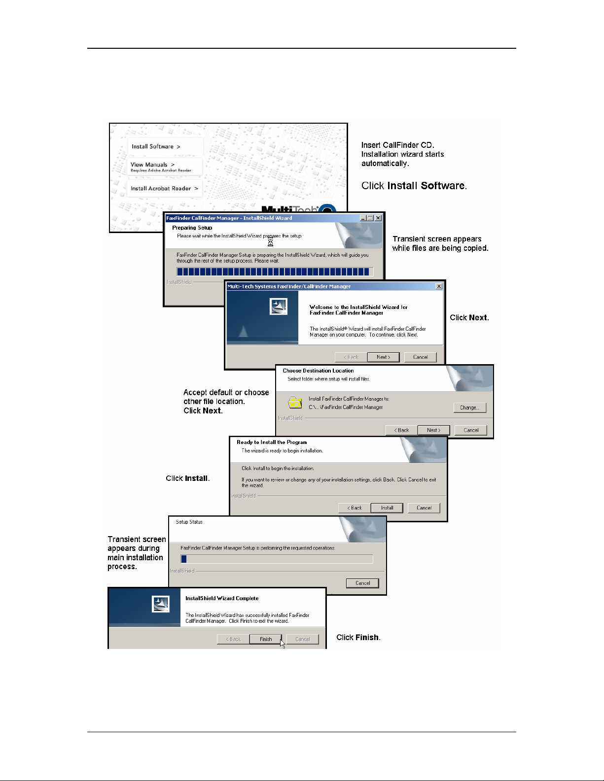
Chapter 6: FFCF Manager Installation
Installing FFCF Manager Software
The process of installing the FFCF software is explained in the illustration below.
Multi-Tech Systems, Inc. CF220 CallFinder User Guide 50
Page 51

Chapter 6: FFCF Manager Installation
Uninstalling or Reinstalling the FFCF Manager Software
1. Go to Start | Settings | Control Panel | Add or Remove Programs. (The menu director
location of the ‘Add/Remove Programs’ function varies for different types of Windows operating
systems.)
2. Select the FaxFinder CallFinder Manager program and click Remove.
Multi-Tech Systems, Inc. CF220 CallFinder User Guide 51
Page 52

Chapter 6: FFCF Manager Installation
3. A transient screen will appear while the ‘wizard’ program prepares to un-install the software.
4. At the ‘Welcome’ screen, select “Remove” to uninstall the FFCF Manager software or select
“Repair” (or “Modify”) as needed to re-install or alter the existing installation of the software.
Then click Next.
Multi-Tech Systems, Inc. CF220 CallFinder User Guide 52
Page 53

Chapter 6: FFCF Manager Installation
5. At the next screen, confirm your decision to uninstall the FFCF Manager software by clicking
Yes.
6. A transient screen appears while files are being removed.
Multi-Tech Systems, Inc. CF220 CallFinder User Guide 53
Page 54

7. At the ‘completion’ screen, click Finish.
Chapter 6: FFCF Manager Installation
Multi-Tech Systems, Inc. CF220 CallFinder User Guide 54
Page 55

Chapter 7: FFCF Manager Operation
Chapter 7 - FFCF Manager
Operation
Introduction
The commands of the FFCF Manager software are accessible in the program’s pulldown Edit
menu, and through a right-click menu that becomes available when a particular CallFinder is
selected in the program’s main screen.
FFCF Manager Command Summary
How to Access Command Command Name Summary
Edit Menu
Right-Click on CallFinder Unit
Synchronize Phonebooks Copies main phonebook into other
Add CallFinder Makes another CallFinder unit part
Delete CallFinder Removes a CallFinder unit from
Save Configuration Saves a group of telephony and IP
Restore Configuration Re-installs a previously saved
Update [Firmware] Updates CallFinder’s “server”
Set Phonebook Sharing Determines whether a CallFinder
[View] Properties Shows IP address and Username
CallFinder units.
of the system.
the system.
settings for a CallFinder unit.
group of telephony & IP settings
into a CallFinder unit.
firmware and its channel firmware.
unit in a system has the main
phonebook, receives a copy of the
phonebook, or operates
independently.
of CallFinder unit.
Multi-Tech Systems, Inc. CF220 CallFinder User Guide 55
Page 56

Chapter 7: FFCF Manager Operation
Opening the FFCF Manager Software
1. To launch the FFCF Manager program from the Windows desktop, go to Start | Programs |
FaxFinder/CallFinder Manager | FaxFinder/CallFinder Manager.
2. The FFCF Manager main screen will appear.
Multi-Tech Systems, Inc. CF220 CallFinder User Guide 56
Page 57

Chapter 7: FFCF Manager Operation
FFCF Manager Main Screen
The FFCF Manager’s main screen lists the CallFinder units that are working together as a
system. The system generally can consist of one CallFinder functioning as a master or server
unit (designated as Primary) and one or more CallFinders functioning as client or slave units
(designated as Copy). CallFinder units functioning without reliance on a server unit (designated
as Independent) can also be part of the system. The FFCF Manager is in contact with all the
CallFinder units of its system through the Ethernet network (Internet or private IP network) to
which all are connected.
Multi-Tech Systems, Inc. CF220 CallFinder User Guide 57
Page 58

Main Screen Menu or Column Description
Chapter 7: FFCF Manager Operation
File menu
Contains the Exit command which closes
the FFCF Manager program.
Edit menu Allows you to add a CallFinder unit to the
system and synchronize phonebooks from
Primary CallFinder units to Copy
CallFinder units within the system.
Help menu Online help is not currently supported.
See manuals.
Device column Lists the CallFinder units in the system
indicating the IP address, model number,
and phonebook sharing status for each.
Status column Indicates the current operating condition of
the FFCF Manager software with respect to
the CallFinder unit.
Possible states are:
not logged in: FFCF Mgr software is not
logged into CF;
logging in: FFCF Mgr software is in process
of logging into CF;
idle: status during normal CF operation;
updating FaxFinder/CallFinder: new version
of firmware is being loaded onto the
CallFinder server unit;
updating modem: new version of firmware
is being loaded onto the DID modem
channel of the CallFinder server unit;
login failure – device busy: appears when
the FFCF Manager software tries to log
into the CallFinder while it is handling a
call.
login failure – device not found: appears
when CallFinder server cannot be
contacted by FFCF Manager.
Version column Indicates the version of CallFinder server
software operating on the CallFinder unit.
Multi-Tech Systems, Inc. CF220 CallFinder User Guide 58
Page 59

FFCF Manager “Edit” Menu
Edit Menu Command Description
Chapter 7: FFCF Manager Operation
Synchronize Phonebooks
Transfers phonebook data from a Primary
CallFinder unit to all CallFinders designated
as Copy units. The phonebook sharing
statuses of the CallFinders (Primary, Copy,
or Independent) involved must be set in
advance. That is, one CallFinder must be
set as the Primary unit. One or more other
CallFinders must be set as Copy units
designated to accept phonebook data from
that particular Primary CallFinder.
Independent CallFinders may be in the
system but they do not participate in
phonebook sharing.
During synchronization, administrative
phonebook parameters are not copied. In
this way, the Copy units retain their entries
for Unassigned Number, Administrator
Password, and other parameters that must
remain unique to each CallFinder unit.
When the Synchronize Phonebooks
command is invoked, the Primary unit
copies its phonebook data into each Copy
unit, one at a time, in sequence until all
Copy units have received the data. Control
screens appear before each Copy unit
receives its download and the download
can be canceled for any particular Copy
unit.
Add FaxFinder/CallFinder
Multi-Tech Systems, Inc. CF220 CallFinder User Guide 59
Brings up the Add FaxFinder/CallFinder
Address screen. On this ‘Add’ screen, you
enter the IP address, User Name, and
Password of CallFinder units to be included
in your system.
Page 60

Chapter 7: FFCF Manager Operation
Synchronizing Phonebooks
When CallFinder phonebooks are synchronized, all non-administrative listings match. One
CallFinder unit (the Primary unit) holds the master list that is transmitted (using the Synchronize
Phonebooks command) to other CallFinder units in the system (Copy units). CallFinder units
can operate in same system but have independent phonebooks, in which case they are
designated Independent.
Synchronizing phonebooks entails three steps:
1. Designating one CallFinder as the master phone book. In the main FFCF Manager screen,
right-click on the unit to be designated as master, scroll to Set Phone Book Sharing, and select
Primary.
2. Designating all other CallFinder units participating in phonebook sharing as Copy units. In the
main FFCF Manager screen, right-click on each unit to share the master phonebook, and select
Copy.
Multi-Tech Systems, Inc. CF220 CallFinder User Guide 60
Page 61

Chapter 7: FFCF Manager Operation
3. Invoking synchronization. In the main FFCF Manager screen, open the Edit menu and select
Synchronize Phonebooks. The Synchronize Phone Books screen will appear along with a
series of transient screens (denoting tftp data transfers) and confirmation screens (where you
click OK to proceed).
After the master phonebook has been transferred to the first Copy CallFinder unit and that unit
has been rebooted, the FFCF Manager will automatically begin synchronizing the additional
Copy CallFinder unit in the system (if any) until all have been synchronized.
To see the newly synchronized phonebook list in each Copy CallFinder unit, you must update the
Phone Book screen by clicking on the Phone Book button (to the right of Administration) in the
list at the top of the screen.
Multi-Tech Systems, Inc. CF220 CallFinder User Guide 61
Page 62

Chapter 7: FFCF Manager Operation
Adding CallFinders
Any CallFinder unit to be added to the system and come under the management of the FFCF
Manager software must be connected to the same IP network as the computer running the FFCF
Manager software.
To add a CallFinder to the system, start at the main FFCF Manager screen. Open the Edit menu
and select Add FaxFinder/CallFinder. When the Add FaxFinder/CallFinder Address screen
appears, enter the IP address, Username, and Password for the unit you are adding to the
system. Then click OK.
Multi-Tech Systems, Inc. CF220 CallFinder User Guide 62
Page 63

Chapter 7: FFCF Manager Operation
Right-Click Menu for Selected CallFinder Device
Right-Click Menu Command Description
Delete Dis-associates the selected CallFinder unit
from the system of CallFinders listed in the
FFCF software Device column.
Save Configuration Saves the settings of the CallFinder’s built-
in software, including the phonebook, on the
PC on which the FFCF Manager software is
running.
Restore Configuration For the selected CallFinder unit, this
command re-imports a previously saved
version of the unit’s software settings
(including phonebook) back into that
CallFinder unit.
Update [firmware] Lets you install the latest firmware for the
CallFinder server and/or its ‘channels’ (DID
modems).
Set Phone Book Sharing Lets you designate the selected CallFinder
unit as either “Independent,” “Primary,” or
“Copy.” The Primary phone book is the
source list that can be transferred to
CallFinders in the system that have been
designated as Copy. Independent
CallFinder units do not share phone book
information.
Default= Independent
Properties Displays IP address, user name, and
password of selected CallFinder unit. (For
the password, only the number of
characters is shown.)
Multi-Tech Systems, Inc. CF220 CallFinder User Guide 63
Page 64

Chapter 7: FFCF Manager Operation
Deleting a CallFinder
Invoking the Delete command removes the selected CallFinder unit from the system. Once
deleted, the CallFinder unit will no longer be under the management of the FFCF Manager
software. Click Yes at the ‘confirmation’ screen to complete the deletion command.
Multi-Tech Systems, Inc. CF220 CallFinder User Guide 64
Page 65

Chapter 7: FFCF Manager Operation
Saving a Configuration
The CallFinder saves all of its settings (IP address, password, DID channel modem parameters,
phone book, etc.) internally. This group of settings is its configuration. This same group of
settings can be saved on the computer running the FFCF Manager software. Once saved, the
configuration can be retrieved from the computer and re-installed onto the CallFinder unit using
the Restore Configuration command.
To save the configuration for a particular CallFinder unit, select the unit in the main FFCF
Manager screen, right-click on it, and select Save Configuration. Choose the location at which
the configuration file will be stored and click OK. Then, at the ‘confirmation’ screen, click OK
again.
Multi-Tech Systems, Inc. CF220 CallFinder User Guide 65
Page 66

Chapter 7: FFCF Manager Operation
Restoring a Configuration
To re-install on the CallFinder unit a group of settings (configuration) previously saved on the
computer running the FFCF Manager software, use the Restore Configuration command. FFCF
Manager will browse, by default, to an automatically determined directory that contains a saved
configuration.
Multi-Tech Systems, Inc. CF220 CallFinder User Guide 66
Page 67

Chapter 7: FFCF Manager Operation
Updating Firmware
When Update command is invoked, the Update CallFinder N.N.N.N screen appears. From this
screen you specify which device (server or DID channel modem) to update with which firmware
file. From this screen, you can also identify the firmware versions currently installed and initiate
the update process.
Update CallFinder N.N.N.N Field Description
Status
Progress Bar
File Name
Browse button Use to locate firmware file to be installed.
CallFinder update select
Start Update button Initiates flashing of firmware.
Get Versions button
main pane of window
Identifies the current condition of the
CallFinder or the current process underway.
Shows how far current process is from
completion.
Lists name of firmware file to be used to
update CallFinder server or DID channel
modem.
Identifies which device (server or DID
channel modem) to be updated.
Press for listing of versions of firmware for
CallFinder server and DID channel
modems.
Presents CallFinder status and details of
updating processes as they occur.
Multi-Tech Systems, Inc. CF220 CallFinder User Guide 67
Page 68

Chapter 7: FFCF Manager Operation
Setting Phone Book Sharing
The phonebook of a Primary CallFinder unit is a source or central phonebook. Phone numbers
should be entered into this phonebook. The central phonebook list is downloaded (by use of
Synchronize Phonebooks command) from the Primary CallFinder unit into the phonebook of
each Copy CallFinder unit. If phone numbers are added to the phonebook of a Copy CallFinder
phonebook, they will be overwritten and lost at the next Synchronize Phonebooks command.
Phonebooks of Independent CallFinder units do not participate in phonebook sharing.
Viewing Properties
The Properties command brings up the FaxFinder/CallFinder – N.N.N.N screen on which you
can view the IP Address and Username of the CallFinder and determine the number of
characters in its Password.
Multi-Tech Systems, Inc. CF220 CallFinder User Guide 68
Page 69

Chapter 7: FFCF Manager Operation
Firmware Updating Process - Detailed
Over time, new versions of CallFinder firmware will be issued. When these newer versions
become available, you will want to secure the firmware files (typically by downloading them from
the MultiTech web site) and install them in the CallFinder.
There are three parts to a full firmware update:
(a) updating DID Channel1/Modem firmware (with file name of the form
gpqg<x><y>.hex; where x is a number and y is a letter),
(b) updating DID Channel2/Modem firmware (same file name as above), and
(c) updating CallFinder server firmware (with file name of the form CF220-<x>-<yz>.bin).
NOTE: You must have the update files on your computer before beginning this
procedure. The latest version of these files will be available on the MultiTech
web site. Put them in a directory on a computer connected to the network on
which the CallFinder unit is running.
NOTE: Updating the CallFinder unit will take it out of operation for a few minutes (allow
10 minutes for each update if you already have the new firmware in a directory
on the host computer). Do the update at a time that is not critical to your
organization’s usage of DID service.
To update firmware, follow the steps shown below.
CallFinder Channel-Modem Firmware Update
1. Bring up the FaxFinder/CallFinder Manager software main screen. In the Device column,
identify the CallFinder unit on which the update is to be done. Be sure that the Status of that
CallFinder unit is
handling a call.) Select that CallFinder unit and right-click on it. In the menu that appears,
Update.
select
idle before continuing. (You cannot update the CallFinder while it is
Multi-Tech Systems, Inc. CF220 CallFinder User Guide 69
Page 70

Chapter 7: FFCF Manager Operation
2. The Update CallFinder N.N.N.N screen will appear. The current firmware versions for the
CallFinder’s DID modems, Channel 1 and Channel 2, will be listed in the main window.
In the bottom (and largest) pane of the Update CallFinder n.n.n.n window, read the list and
write down the version of firmware currently in use for the two DID-channel modems.
Compare these versions with the update file that you plan to use.
be installed really does supersede the one currently installed.
CallFinder Update Select field, select the DID-channel modem that you want to
In the
Make sure that the file to
update (Channel 1 or Channel 2).
Multi-Tech Systems, Inc. CF220 CallFinder User Guide 70
Page 71

3. Browse to the location of the most recent firmware file.
Chapter 7: FFCF Manager Operation
4. Click Start Update.
5. The
CallFinder – Confirm Update screen will appear. Click OK.
Multi-Tech Systems, Inc. CF220 CallFinder User Guide 71
Page 72

Chapter 7: FFCF Manager Operation
6. The updating process will take as long as a minute. During this time, several messages
will appear in the
Update CallFinder N.N.N.N window. A transient TFTP screen may appear
briefly. If the updating process has been successful, the final message line will say “Finished
– The FaxFinder/CallFinder is ready.”
7. Repeat steps 1-6 for the second channel of this CallFinder unit. For consistency of
operation, update both channels of all CallFinder units in the system.
8. The updating process is now complete. Click the “X” in the upper-right corner to return to
the main
FFCF Manager screen.
Multi-Tech Systems, Inc. CF220 CallFinder User Guide 72
Page 73

CallFinder Server Firmware Update
Chapter 7: FFCF Manager Operation
1. Bring up the
FaxFinder/CallFinder Manager software main screen. In the Device column,
identify the CallFinder unit on which the update is to be done. Be sure that the Status of that
CallFinder unit is
idle before continuing. (You cannot update the CallFinder while it is
handling a call.) Select that CallFinder unit and right-click on it. In the menu that appears,
Update.
select
2. The
Update CallFinder N.N.N.N screen will appear. The current firmware versions for the
CallFinder server, for Channel 1, and for Channel 2 will be listed in the main window.
Multi-Tech Systems, Inc. CF220 CallFinder User Guide 73
Page 74

Chapter 7: FFCF Manager Operation
In the bottom (and largest) pane of the Update CallFinder N.N.N.N window, read the list and
write down the version of firmware currently in use for the CallFinder server and its two DIDchannel modems. Compare these versions with the update files that you plan to use. Make
sure that the files to be installed really do supersede the ones currently installed on the
CallFinder.
CallFinder Update Select field, select “CallFinder firmware.”
In the
3. Browse to the location of the most recent firmware file.
4. Click Start Update.
5. The
CallFinder – Confirm Update screen will appear. Click OK.
Multi-Tech Systems, Inc. CF220 CallFinder User Guide 74
Page 75

Chapter 7: FFCF Manager Operation
6. The updating process will take as long as a minute. During this time, several messages
will appear in the
Update CallFinder N.N.N.N window. A transient TFTP screen may appear
briefly. If the updating process has been successful, the final message line will say “Finished
– The FaxFinder/CallFinder is ready.”
7. Close the Update CallFinder N.N.N.N window. In the main FFCF Manager window, the
updated version will be listed.
Multi-Tech Systems, Inc. CF220 CallFinder User Guide 75
Page 76

Chapter 7: FFCF Manager Operation
8. Repeat steps 1-7 for each CallFinder unit in the system.
NOTE: For proper operation of the CallFinder system, including the sharing of Phone
Book data, the server firmware version for all CallFinder units must be the
same.
9. The updating process is now complete. Click the “X” in the upper-right corner to return to
the main
FFCF Manager screen.
Multi-Tech Systems, Inc. CF220 CallFinder User Guide 76
Page 77

Chapter 8: Troubleshooting
Chapter 8: Troubleshooting
1. What if I can't see the web page for my CallFinder ?
REMEDY: Is the status LED on the CallFinder unit blinking? If not, then the unit is either malfunctioning
or not turned on. If the Status LED is blinking, then verify that the Admin PC is actually on the
same subnet as the CallFinder and that the CallFinder can be “pinged.”
Launch a Command Prompt.
(In WinNT, go to Start | Programs | Command Prompt.
In WinXP, go to Start | All Programs | Accessories | Command Prompt.
In Win2000, go to Start | Programs | Accessories | Command Prompt.)
Type ipconfig to verify that the Admin PC’s IP address is in the same network as the
CallFinder’s IP address.
Then type ping 192.168.2.1 and press Return.
If the CallFinder unit does reply to the ping and you are still unable to view the CallFinder web
page, then call Multi-Tech Tech Support for more assistance (1-800-972-2439).
2. What if I don't get an email when I set the mail server address ?
This pertains to the procedure “Setting Up the Mail Server.”
The email may have failed due to one of three causes:
(A) the name server is unresolvable (in this case, “Bad Mail Server Address” will appear in the Email
Status field of the Current Status screen),
(B) the mail server cannot be contacted; or
(C) the client PC running the mail software cannot connect to the mail server.
CAUSE A: During transmission, the name server’s address could not be resolved (that is, the CallFinder
unit could not contact your name server).
RESPONSE A: Contact the CallFinder unit using telnet and try to ping the name server.
telnet 192.168.x.x
user: admin
password: admin
# ping 192.168.y.y (where this is the address of the name server)
If the name server ping fails, you must determine why it failed.
The name server may not be contact-able because it is on a different subnet. The name
server ping could also fail because the default gateway has been set incorrectly.
If the name server ping succeeds, then try to ping the mail server using its domain
name.
# ping mail.ourcompany.com
If pinging the mail server by its domain name fails, then try pinging it by using its IP
address (if this can be determined). If you succeed in pinging the mail server by its IP
address but yet it cannot be pinged via its domain name, then the name server is not
functioning correctly (or the device at the name server’s IP address is not a name
server).
Multi-Tech Systems, Inc. CF220 CallFinder User Guide 77
Page 78

Chapter 8: Troubleshooting
No email message after mail server setup (cont’d)
If the mail server can be pinged neither by its domain name nor by its IP address, then
consider item B below.
CAUSE B: The mail server is not running or cannot be contacted from the CallFinder unit.
RESPONSE B: Verify that the mail server is running by sending an email to yourself using your email
software.
If you cannot send an email to yourself using your email software, then the mail server is
not running and you should find out why.
If you can send an email to yourself using the email software, then there is a problem
between your mail server and the CallFinder unit. Call Multi-Tech Tech Support (1-800972-2439).
Username/Password Issues. Some mail servers require that the CallFinder use its
Username and Password to log into the mail server. Others do not. This Username and
Password are specified in the Administration: SMTP Configuration screen. If the mail
server requires the CallFinder to have a Username and Password and none is provided,
access will be denied. Conversely, if the mail server does not require a Username and
Password and these have been specified anyway, again access will be denied. If call
logs are not reaching the administrator, it may be because of such Username/Password
issues.
CAUSE C: The client PC running the mail software cannot connect to the mail server.
RESPONSE C: If you, as a client, cannot send yourself an email, then contact your administrator; there
may be a problem with your mail server.
Multi-Tech Systems, Inc. CF220 CallFinder User Guide 78
Page 79

Chapter 8: Troubleshooting
3. What if the CallFinder channel doesn't answer a call on the DID line?
REMEDY. Use this procedure if Channel Configuration cannot be confirmed (that is, if during a test call
to one of the system's DID phone numbers, you fail to see the "Waiting for Connect" State in
the Current Status: Channel-1/Channel-2 screen and if you fail to hear voice-- both the
state and the sound must be observable).
A. Situate yourself in a place where you can see the CallFinder unit and, simultaneously,
use a phone on a regular POTS line.
B. From that ordinary POTS phone, dial one of the DID phone numbers that is active in the
system.
C. As the call is completed, watch the LEDs on the front panel of the CallFinder unit.
If the DID LED remains off, then there is probably a telephony problem. That is, the DID
phone line has not been activated or configured properly. Call the telephone company.
If the DID LED comes ON, then there is something wrong with the CallFinder software.
Call MultiTech Tech Support (1-800-972-2439).
Polarity Check. Incorrect DID polarity could also prevent calls from being answered.
D.
Signs of incorrect polarity:
(1) outside party originating call to DID number gets immediate busy
signal after dialing;
(2) line suddenly disconnects just when call should go through.
Call Logs. If calls have failed, you can check the CallFinder’s call logs to see the actual
E.
DID number that the CallFinder received. Sometimes corrupted DID numbers are
presented to the CallFinder. In any event, the call logs can help to track down the error
involved.
4. What if the CallFinder presents the wrong time of day?
Or, what if the CallFinder marks calls with the wrong time of day? What if the message
“SNTP Error …” appears in the
REMEDY: The CallFinder may have lost contact with the time server. By default, the CallFinder
obtains its time from an Internet source. If the CallFinder is isolated from the Internet, then
you must provide a different time source within the private ethernet network.
Time Server Status field of the Current Status screen?
5. What if an immediate busy signal is received when dialing in on the DID line?
REMEDY
A. Check for “Busied Out” condition of channel on Current Status screen. If the channel is
busied out, click “Initialize Channel.”
B. Reverse DID line polarity in
Channel Configuration screen.
6. What if the line suddenly disconnects just when a call is about to be
connected?
REMEDY: Reverse DID line polarity in Channel Configuration screen.
Multi-Tech Systems, Inc. CF220 CallFinder User Guide 79
Page 80

Chapter 9: Regulatory Information
Chapter 9 – Regulatory Information
47 CFR Part 68 Telecom
1. This equipment complies with Part 68 of the 47 CFR rules and the requirements adopted by the ACTA.
Located on this equipment is a label that contains, among other information, the registration number and
ringer equivalence number (REN) for this equipment or a product identifier in the format:
For current products is US:AAAEQ##Txxxx.
For legacy products is AU7USA-xxxxx-xx-x.
If requested, this number must be provided to the telephone company.
2. A plug and jack used to connect this equipment to the premises wiring and telephone network must
comply with the applicable 47 CFR Part 68 rules and requirements adopted by the ACTA. It’s
designed to be connected to a compatible modular jack that is also compliant.
3. The ringer equivalence number (REN) is used to determine the number of devices that may be
connected to a telephone line. Excessive RENs on a telephone line may result in the devices not
ringing in response to an incoming call. In most but not all areas, the sum of RENs should not exceed
five (5.0). To be certain of the number of devices that may be connected to a line, as determined by
the total RENs, contact the local telephone company. For products approved after July 23, 2001, the
REN for this product is part of the product identifier that has the format US:AAAEQ##Txxxx. The
digits represented by ## are the REN without a decimal point (
products, the REN is separately shown on the label.
e.g., 03 is a REN of 0.3). For earlier
4. If this equipment causes harm to the telephone network, the telephone company will notify you in
advance that temporary discontinuance of service may be required. But if advance notice isn't
practical, the telephone company will notify the customer as soon as possible. Also, you will be
advised of your right to file a complaint with the FCC if you believe it is necessary.
5. The telephone company may make changes in its facilities, equipment, operations or procedures that
could affect the operation of the equipment. If this happens, the telephone company will provide
advance notice in order for you to make necessary modifications to maintain uninterrupted service.
6. If trouble is experienced with this equipment, please contact Multi-Tech Systems, Inc. at the address
shown below for details of how to have the repairs made
telephone network, the telephone company may request that you disconnect the equipment until the
problem is resolved.
7. Connection to party line service is subject to state tariffs. Contact the state public utility commission,
public service commission or corporation commission for information.
8. No repairs are to be made by you. Repairs are to be made only by Multi-Tech Systems or its
licensees. Unauthorized repairs void registration and warranty.
9. If your home has specially wired alarm equipment connected to the telephone line, ensure the
installation of this equipment does not disable your alarm equipment.
If you have questions about what will disable alarm equipment, consult your telephone company or a
qualified installer.
10. Connection to party line service is subject to state tariffs. Contact the state public utility commission,
public service commission or corporation commission for information.
. If the equipment is causing harm to the
11. This equipment is hearing aid compatible.
Multi-Tech Systems, Inc. CF220 CallFinder User Guide 80
Page 81

Chapter 9: Regulatory Information
12. Manufacturing Information:
Manufacturer: Multi-Tech Systems, Inc.
Trade Name: CallFinder
Model Number: CF220
Registration No: US: AU7OTNANCF220
Ringer Equivalence: 0.4B
Modular Jack (USOC): RJ11C or RJ11W (single line),
RJ12
Service Center in USA: Multi-Tech Systems, Inc.
2205 Woodale Drive
Mounds View, MN 55112 U.S.A.
(763) 785-3500
(763) 785-9874 Fax
47 CFR Part 15 Regulation
This equipment has been tested and found to comply with the limits for a Class B digital device, pursuant
to 47 CFR Part 15 regulations. The stated limits in this regulation are designed to provide reasonable
protection against harmful interference in a residential installation. This equipment generates, uses, and
can radiate radio frequency energy, and if not installed and used in accordance with the instructions, may
cause harmful interference to radio communications. However, there is no guarantee that interference will
not occur in a particular installation. If this equipment does cause harmful interference to radio or
television reception, which can be determined by turning the equipment off and on, the user is
encouraged to try to correct the interference by one or more of the following measures:
Reorient or relocate the receiving antenna.
Increase the separation between the equipment and receiver.
Plug the equipment into an outlet on a circuit different from that to which the receiver is connected.
Consult the dealer or an experienced radio/TV technician for help.
This device complies with Part 15 of the CFR 47 rules. Operation of this device is subject to the following
conditions: (1) This device may not cause harmful interference, and (2) this device must accept any
interference that may cause undesired operation.
Warning: Changes or modifications to this unit not expressly approved by the party responsible
for compliance could void the user’s authority to operate the equipment.
Fax Branding Statement
The Telephone Consumer Protection Act of 1991 makes it unlawful for any person to use a computer or
other electronic device, including fax machines, to send any message unless such message clearly
contains the following information:
• Date and time the message is sent
• Identification of the business or other entity, or other individual sending the message
• Telephone number of the sending machine or such business, other entity, or individual
This information is to appear in a margin at the top or bottom of each transmitted page or on the first page
of the transmission. (Adding this information in the margin is referred to as fax branding).
Any number of fax software packages can be used with this product. Refer to the fax software manual for
setup details. Typically, the fax branding information must be entered via the configuration menu of the
software.
Multi-Tech Systems, Inc. CF220 CallFinder User Guide 81
Page 82

Chapter 9: Regulatory Information
Canadian Limitations Notice
Notice: The ringer equivalence number (REN) assigned to each terminal device provides an indication of
the maximum number of terminals allowed to be connected to a telephone interface. The termination on
an interface may consist of any combination of devices subject only to the requirement that the sum of the
ringer equivalence numbers of all the devices does not exceed 5.
Notice: The Industry Canada label identifies certified equipment. This certification means that the
equipment meets certain telecommunications network protective, operational, and safety requirements.
The Industry Canada label does not guarantee the equipment will operate to the user’s satisfaction.
Before installing this equipment, users should ensure that it is permissible to be connected to the facilities
of the local telecommunications company. The equipment must also be installed using an acceptable
method of connection. The customer should be aware that compliance with the above conditions may not
prevent degradation of service in some situations. Repairs to certified equipment should be made by an
authorized Canadian maintenance facility designated by the supplier. Any repairs or alterations made by
the user to this equipment or equipment malfunctions may give the telecommunications company cause
to request the user to disconnect the equipment.
Users should ensure for their own protection that the electrical ground connections of the power utility,
telephone lines and internal metallic water pipe system, if present, are connected together. This
precaution may be particularly important in rural areas.
Caution: Users should not attempt to make such connections themselves, but should contact the
appropriate electric inspection authority, or electrician, as appropriate.
Industry Canada
This Class B digital apparatus meets all requirements of the Canadian Interference-Causing Equipment
Regulations.
Cet appareil numérique de la classe B respecte toutes les exigences du Reglement Canadien sur le
matériel brouilleur.
Multi-Tech Systems, Inc. CF220 CallFinder User Guide 82
Page 83

Chapter 10: Warranty, Service, & Repair
Chapter 10: Warranty, Service, &
Repair
Multi-Tech Warranty Statement
Multi-Tech Systems, Inc., (hereafter “MTS”) warrants that its products will be free from defects in material
or workmanship for a period of two, five, or ten years (depending on model) from date of purchase, or if
proof of purchase is not provided, two, five, or ten years (depending on model) from date of shipment.
MTS MAKES NO OTHER WARRANTY, EXPRESS OR IMPLIED, AND ALL IMPLIED WARRANTIES OF
MERCHANTABILITY AND FITNESS FOR A PARTICULAR PURPOSE ARE HEREBY DISCLAIMED.
This warranty does not apply to any products which have been damaged by lightning storms, water, or
power surges or which have been neglected, altered, abused, used for a purpose other than the one for
which they were manufactured, repaired by Customer or any party without MTS’s written authorization, or
used in any manner inconsistent with MTS’s instructions.
MTS’s entire obligation under this warranty shall be limited (at MTS’s option) to repair or replacement of
any products which prove to be defective within the warranty period or, at MTS’s option, issuance of a
refund of the purchase price. Defective products must be returned by Customer to MTS’s factory —
transportation prepaid.
MTS WILL NOT BE LIABLE FOR CONSEQUENTIAL DAMAGES, AND UNDER NO CIRCUMSTANCES
WILL ITS LIABILITY EXCEED THE PRICE FOR DEFECTIVE PRODUCTS.
Repair Procedures for U.S. and Canadian Customers
In the event that service is required, products may be shipped, freight prepaid, to our Mounds View,
Minnesota factory:
Multi-Tech Systems, Inc.
2205 Woodale Drive
Mounds View, MN 55112
Attn: Repairs, Serial # ____________
A Returned Materials Authorization (RMA) is not required. Return shipping charges (surface) will be paid
by MTS to destinations in U.S. and Canada.
Please include, inside the shipping box, a description of the problem, a return shipping address (must
have street address, not P.O. Box), your telephone number, and if the product is out of warranty, a check
or purchase order for repair charges.
For out of warranty repair charges, go to www.multitech.com/DOCUMENTS/Company/warranty/
Extended two-year overnight replacement service agreements are available for selected products. Please
call MTS at (888) 288-5470, extension 5308 or visit our web site at
www.multitech.com/PARTNERS/Programs/orc/
Please direct your questions regarding technical matters, product configuration, verification that the
product is defective, etc., to our Technical Support department at (800) 972-2439 or email
support@multitech.com
billing, etc., to our Repair Accounting department at (800) 328-9717 or (763) 717-5631, or email
mtsrepair@multitech.com
Repairs for damages caused by lightning storms, water, power surges, incorrect installation, physical
abuse, or user-caused damages are billed on a time-plus-materials basis.
. Please direct your questions regarding repair expediting, receiving, shipping,
.
for details on rates and coverage’s.
Repair Procedures for International Customers (Outside U.S.A. and Canada)
Your original point of purchase Reseller may offer the quickest and most economical repair option for your
Multi-Tech product. You may also contact any Multi-Tech sales office for information about the nearest
distributor or other repair service for your Multi-Tech product. The Multi-Tech sales office directory is
available at www.multitech.com/PARTNERS/Channels/offices/
Multi-Tech Systems, Inc. CF220 CallFinder User Guide 83
Page 84

Chapter 10: Warranty, Service, & Repair
In the event that factory service is required, products may be shipped, freight prepaid to our Mounds
View, Minnesota factory. Recommended international shipment methods are via Federal Express, UPS or
DHL courier services, or by airmail parcel post; shipments made by any other method will be refused. A
Returned Materials Authorization (RMA) is required for products shipped from outside the U.S.A. and
Canada. Please contact us for return authorization and shipping instructions on any International
shipments to the U.S.A. Please include, inside the shipping box, a description of the problem, a return
shipping address (must have street address, not P.O. Box), your telephone number, and if the product is
out of warranty, a check drawn on a U.S. bank or your company’s purchase order for repair charges.
Repaired units shall be shipped freight collect, unless other arrangements are made in advance.
Please direct your questions regarding technical matters, product configuration, verification that the
product is defective, etc., to our Technical Support department nearest you or email
support@multitech.com
receiving, shipping, billing, etc., to our Repair Accounting department at +(763) 717-5631 in the U.S.A., or
email mtsrepair@multitech.com
Repairs for damages caused by lightning storms, water, power surges, incorrect installation, physical
abuse, or user-caused damages are billed on a time-plus-materials basis.
. When calling the U.S., please direct your questions regarding repair expediting,
.
Repair Procedures for International Distributors
Distributors should contact Amex, Inc., for information about the repairs for your Multi-Tech product.
Amex, Inc.
2724 Summer Street NE
Minneapolis, MN 55413 U.S.A.
Tel: +(612) 331-3251
Fax: +(612) 331-3180
Email: info@amexinc.com
Please direct your questions regarding technical matters, product configuration, verification that the
product is defective, etc., to our International Technical Support department at +(763)717-5863. When
calling the U.S., please direct your questions regarding repair expediting, receiving, shipping, billing, etc.,
to our Repair Accounting department at +(763) 717-5631 in the U.S.A. or email mtsrepair@multitech.com
Repairs for damages caused by lightning storms, water, power surges, incorrect installation, physical
abuse, or user-caused damages are billed on a time-plus-materials basis.
.
Multi-Tech Systems, Inc. CF220 CallFinder User Guide 84
 Loading...