

Page 1

User’s Guide
Page 2

Page 3
Notices
For further assistance
please contact us at:
Worldwide Headquarters
2195 Keating Cross Road
Saanichton, BC
Canada V8M 2A5
Tel: 1-250-652-7100
Fax: 1-250-652-0411
Email: support@pwrm.com
www.pwrm.com
© 2003 Power Measurement
Printed in Canada
Revision Date: May 9, 2003
70000-0176-01
Danger
This symbol indicates the presence of dangerous voltage within and
outside the product enclosure that may constitute a risk of electric
shock, serious injury or death to persons if proper precautions are not
followed.
Caution
This symbol alerts the user to the presence of hazards that may cause
minor or moderate injury to persons, damage to property or damage
to the device itself, if proper precautions are not followed.
Note
This symbol directs the user’s attention to important installation,
operating and maintenance instructions.
Installation Considerations
Installation and maintenance of the ION 7500 / ION 7600 meter should only be
performed by qualified, competent personnel that have appropriate training and
experience with high voltage and current devices. The meter must be installed in
accordance with all Local and National Electrical Codes.
DANGER
Failure to observe the following instructions may result in severe injury or death.
During normal operation of the ION 7500 / ION 7600 meter, hazardous voltages
are present on its terminal strips, and throughout the connected potential
transformer (PT), current transformer (CT), digital (status) input, control power
and external I/O circuits. PT and CT secondary circuits are capable of generating
lethal voltages and currents with their primary circuit energized. Follow
standard safety precautions while performing any installation or service work
(i.e. removing PT fuses, shorting CT secondaries, etc).
The terminal strips on the meter base should not be user-accessible after
installation.
Do not use digital output devices for primary protection functions. These
include applications where the devices perform energy limiting functions or
provide protection of people from injury. Do not use the ION 7500 / ION 7600 in
situations where failure of the devices can cause injury or death, or cause
sufficient energy to be released that can start a fire. The meter can be used for
secondary protection functions.
Do not HIPOT/Dielectric test the digital (status) inputs, digital outputs, or
communications terminals. Refer to the label on the ION 7500 / ION 7600 meter
for the maximum voltage level the device can withstand.
Page 4

CAUTION
Observe the following instructions, or permanent damage to the meter may occur.
The ION 7500 / ION 7600 meter offers a range of hardware options that affect
input ratings. The ION 7500 / ION 7600 meter’s serial number label lists all
equipped options. Applying current levels incompatible with the current inputs
will permanently damage the meter. This document provides installation
instructions applicable to each hardware option.
The ION 7500 / ION 7600 meter’s chassis ground must be properly connected to
the switchgear earth ground for the noise and surge protection circuitry to
function correctly. Failure to do so will void the warranty.
Terminal screw torque: Barrier-type (current, voltage, and relay terminal screws:
1.35 Nm (1.00 ft-lbf) max. Captured-wire type (digital inputs/outputs,
communications, power supply: 0.90 Nm (0.66 ft.lbf) max.
FCC Notice
This equipment has been tested and found to comply with the limits for a Class A
digital device, pursuant to Part 15 of the FCC Rules. These limits are designed to
provide reasonable protection against harmful interference when the equipment is
operated in a commercial environment. This equipment generates, uses, and can
radiate radio frequency energy and, if not installed and used in accordance with
the instruction manual, may cause harmful interference to radio communications.
Operation of this equipment in a residential area is likely to cause harmful
interference in which case the user will be required to correct the interference at his
own expense. The Ringer Equivalence Number (REN) for the ION 7500 / ION 7600
optional internal modem is 0.6. Connection to the ION 7500 / ION 7600 internal
modem should be made via an FCC Part 68 compliant telephone cord (not
supplied). The ION 7500 / ION 7600 cannot be used on a public coin phone service
or party line services.
Network Compatibility Notice for the Internal Modem
The internal modem in meters equipped with this option is compatible with the
telephone systems of most countries in the world, with the exception of Australia
and New Zealand. Use in some countries may require modification of the internal
modem’s initialization strings. If problems using the modem on your phone
system occur, please contact Power Measurement Technical Services
Standards Compliance
CSA: Certified to CAN/
CSA C22.2 No.1010-1
Certified to
UL 3111
CE: approved
Page 5

Limitation of Liability
Power Measurement Ltd. (“Power Measurement”) reserves the right to make changes in the
device or its specifications identified in this document without notice. Power Measurement
advises customers to obtain the latest version of the device specifications before placing
orders to verify that the information being relied upon by the customer is current.
Regardless of whether any remedy set forth herein fails of its essential purpose, except to
the extent the following limitation is prohibited by applicable law, Power Measurement
shall not, in any event or under any legal claim or theory (whether based on contract,
indemnity, warranty, tort (including negligence and strict liability) or otherwise), be liable
to the original purchaser or any other person or entity for special, indirect, incidental,
punitive, liquidated, special or consequential damages whatsoever with respect to any
purchased product, including, without limitation, business interruption, loss of use, profit
or revenue, even if Power Measurement has been advised of the possibility of such
damages. To the extent that a limitation or exclusion of consequential damages are
prohibited by applicable law, then Power Measurement’s liability shall be limited to twice
the amount of the relevant purchased product. Not to limit the foregoing, a) Power
Measurement shall not be liable for any claim (other than a claim solely for the breach of one
of the above Warranties that is made in accordance with the above described procedures)
made by the original purchaser, its employees, agents, or contractors for any loss, damage,
or expense incurred due to, caused by, or related to any purchased product; and b) the
above Warranties are the original purchaser's exclusive remedy and Power Measurement
hereby expressly disclaims all other warranties, express or implied, including, without
limitation, warranties of non-infringement and the implied warranties of merchantability
and fitness for a particular purpose.
These limited Warranties shall not apply to any product that has been subject to alteration,
accident, misuse, abuse, neglect or failure to exactly follow Power Measurement's
instructions for operation and maintenance. Any technical assistance provided by Power
Measurement's personnel or representatives in system design shall be deemed to be a
proposal and not a recommendation. The responsibility for determining the feasibility of
such proposals rests with the original purchaser and should be tested by the original
purchaser. It is the original purchaser’s responsibility to determine the suitability of any
product and associated documentation for its purposes. The original purchaser
acknowledges that 100% "up" time is not realizable because of possible hardware or
software defects. The original purchaser recognizes that such defects and failures may cause
inaccuracies or malfunctions. Only the terms expressed in these limited Warranties shall
apply and no distributor, corporation or other entity, individual or employee of Power
Measurement or any other entity is authorized to amend, modify or extend the Warranties
in any way.
The information contained in this document is believed to be accurate at the time of
publication, however, Power Measurement assumes no responsibility for any errors which
may appear here and reserves the right to make changes without notice.
ION, ION Enterprise, ION Meter Shop, ION Setup, ION Wire, ION Reader, PEGASYS,
PowerView, ION 6200, ION 7300, ION 7330, ION 7350, ION 7500, ION 7600, ION 7700, ION
8300, ION 8400, ION 8500, COM32, COM128, Vista, VIP, Designer, Reporter, MeterM@il,
WebMeter, EtherGate, ModemGate, Xpress Card, Feature Packs and “smart energy
everywhere” are either registered trademarks or trademarks of Power Measurement. All
other trademarks are property of their respective owners.
Covered by one or more of the following patents:
U.S. Patent No's 6397155, 6186842, 6185508, 6000034, 5995911, 5828576, 5736847, 5650936,
D459259, D458863, D435471, D432934, D429655, D429533.
Canadian Patent No's 2148076, 2148075.
Other patents pending.
Page 6

Page 7

Contents
Chapter 1 Introduction ..................................................................... 11
Chapter 2 Using The Front Panel ....................................................... 21
◆ ION 7500 and ION 7600 Meters . . . . . . . . . . . . . . . . . . . . . . . . . . . . . . . . . . . 12
◆ The ION meter in an Enterprise Energy Management System . . . . . . . . . . . . . . . 14
Data Display and Analysis Tools . . . . . . . . . . . . . . . . . . . . . . . . . . . . . . . . . . . . . . . . . . . 14
Communications Protocols . . . . . . . . . . . . . . . . . . . . . . . . . . . . . . . . . . . . . . . . . . . . . . . . 16
Digital and Analog I/O Options . . . . . . . . . . . . . . . . . . . . . . . . . . . . . . . . . . . . . . . . . . . . 16
The Meter is Factory-Configured and Ready to Operate . . . . . . . . . . . . . . . . . . . . . . . 17
◆ Firmware Revision History . . . . . . . . . . . . . . . . . . . . . . . . . . . . . . . . . . . . . . . . 18
◆ Using this Guide . . . . . . . . . . . . . . . . . . . . . . . . . . . . . . . . . . . . . . . . . . . . . . . 19
Getting More Information . . . . . . . . . . . . . . . . . . . . . . . . . . . . . . . . . . . . . . . . . . . . . . . . . 19
◆ Displaying Data with the Front Panel . . . . . . . . . . . . . . . . . . . . . . . . . . . . . . . . 22
Display Screen Types . . . . . . . . . . . . . . . . . . . . . . . . . . . . . . . . . . . . . . . . . . . . . . . . . . . . . 23
Default Front Panel Display Screens . . . . . . . . . . . . . . . . . . . . . . . . . . . . . . . . . . . . . . . . 26
◆ Configuring the Meter with the Front Panel . . . . . . . . . . . . . . . . . . . . . . . . . . . . 31
The Front Panel’s Setup Menu . . . . . . . . . . . . . . . . . . . . . . . . . . . . . . . . . . . . . . . . . . . . . . 31
Basic Setup Menu . . . . . . . . . . . . . . . . . . . . . . . . . . . . . . . . . . . . . . . . . . . . . . . . . . . . . . . . 33
Main Setup Menu . . . . . . . . . . . . . . . . . . . . . . . . . . . . . . . . . . . . . . . . . . . . . . . . . . . . . . . . 34
Demand Setup Menu . . . . . . . . . . . . . . . . . . . . . . . . . . . . . . . . . . . . . . . . . . . . . . . . . . . . . 34
Network Setup . . . . . . . . . . . . . . . . . . . . . . . . . . . . . . . . . . . . . . . . . . . . . . . . . . . . . . . . . . . 36
Serial Communications Setup . . . . . . . . . . . . . . . . . . . . . . . . . . . . . . . . . . . . . . . . . . . . . . 38
PQ (Power Quality) Setup . . . . . . . . . . . . . . . . . . . . . . . . . . . . . . . . . . . . . . . . . . . . . . . . . 39
Format Setup Menu . . . . . . . . . . . . . . . . . . . . . . . . . . . . . . . . . . . . . . . . . . . . . . . . . . . . . . . 40
Display Setup Menu . . . . . . . . . . . . . . . . . . . . . . . . . . . . . . . . . . . . . . . . . . . . . . . . . . . . . . 41
Time Setup Menu . . . . . . . . . . . . . . . . . . . . . . . . . . . . . . . . . . . . . . . . . . . . . . . . . . . . . . . . 41
Meter Resets . . . . . . . . . . . . . . . . . . . . . . . . . . . . . . . . . . . . . . . . . . . . . . . . . . . . . . . . . . . . . 43
Security Setup . . . . . . . . . . . . . . . . . . . . . . . . . . . . . . . . . . . . . . . . . . . . . . . . . . . . . . . . . . . 44
◆ Custom Front Panel Displays . . . . . . . . . . . . . . . . . . . . . . . . . . . . . . . . . . . . . . 46
Creating a Front Panel Reset . . . . . . . . . . . . . . . . . . . . . . . . . . . . . . . . . . . . . . . . . . . . . . . 46
Chapter 3 Default Meter Functionality 49
◆ Default Meter Functionality . . . . . . . . . . . . . . . . . . . . . . . . . . . . . . . . . . . . . . . 50
Basic Setup . . . . . . . . . . . . . . . . . . . . . . . . . . . . . . . . . . . . . . . . . . . . . . . . . . . . . . . . . . . . . . 50
Communications Setup . . . . . . . . . . . . . . . . . . . . . . . . . . . . . . . . . . . . . . . . . . . . . . . . . . . 51
Data Logging Setup . . . . . . . . . . . . . . . . . . . . . . . . . . . . . . . . . . . . . . . . . . . . . . . . . . . . . . . 53
Energy Pulsing Setup . . . . . . . . . . . . . . . . . . . . . . . . . . . . . . . . . . . . . . . . . . . . . . . . . . . . . 58
Power Quality Configuration . . . . . . . . . . . . . . . . . . . . . . . . . . . . . . . . . . . . . . . . . . . . . . 59
Setpoint Configuration . . . . . . . . . . . . . . . . . . . . . . . . . . . . . . . . . . . . . . . . . . . . . . . . . . . . 61
Page 8

Meter Clock Configuration . . . . . . . . . . . . . . . . . . . . . . . . . . . . . . . . . . . . . . . . . . . . . . . . 62
Display Setup . . . . . . . . . . . . . . . . . . . . . . . . . . . . . . . . . . . . . . . . . . . . . . . . . . . . . . . . . . . . 63
Demand Setup . . . . . . . . . . . . . . . . . . . . . . . . . . . . . . . . . . . . . . . . . . . . . . . . . . . . . . . . . . . 64
Time of Use Configuration . . . . . . . . . . . . . . . . . . . . . . . . . . . . . . . . . . . . . . . . . . . . . . . . . 65
Factory Information . . . . . . . . . . . . . . . . . . . . . . . . . . . . . . . . . . . . . . . . . . . . . . . . . . . . . . 67
◆ Third Party Protocols . . . . . . . . . . . . . . . . . . . . . . . . . . . . . . . . . . . . . . . . . . . . 68
Using the Modbus RTU Protocol . . . . . . . . . . . . . . . . . . . . . . . . . . . . . . . . . . . . . . . . . . . 69
Using the Modbus/TCP Protocol . . . . . . . . . . . . . . . . . . . . . . . . . . . . . . . . . . . . . . . . . . . 79
Using the DNP 3.00 Protocol . . . . . . . . . . . . . . . . . . . . . . . . . . . . . . . . . . . . . . . . . . . . . . . 80
◆ Restoring the Factory Configuration . . . . . . . . . . . . . . . . . . . . . . . . . . . . . . . . . 85
Chapter 4 Using ION Software ......................................................... 87
◆ ION Enterprise Software . . . . . . . . . . . . . . . . . . . . . . . . . . . . . . . . . . . . . . . . . 88
◆ ION Enterprise: ION Management Console . . . . . . . . . . . . . . . . . . . . . . . . . . . . 89
Configuring Communications . . . . . . . . . . . . . . . . . . . . . . . . . . . . . . . . . . . . . . . . . . . . . . 91
◆ ION Enterprise: Vista . . . . . . . . . . . . . . . . . . . . . . . . . . . . . . . . . . . . . . . . . . . . 93
Displaying Data with Vista . . . . . . . . . . . . . . . . . . . . . . . . . . . . . . . . . . . . . . . . . . . . . . . . 93
Customizing the Vista Interface . . . . . . . . . . . . . . . . . . . . . . . . . . . . . . . . . . . . . . . . . . . 101
◆ ION Enterprise: Designer . . . . . . . . . . . . . . . . . . . . . . . . . . . . . . . . . . . . . . . . 103
Basics of ION Architecture . . . . . . . . . . . . . . . . . . . . . . . . . . . . . . . . . . . . . . . . . . . . . . . . 103
Designer’s Main Configuration Screen . . . . . . . . . . . . . . . . . . . . . . . . . . . . . . . . . . . . . 107
Viewing Real-time Data in Designer . . . . . . . . . . . . . . . . . . . . . . . . . . . . . . . . . . . . . . . 108
Changing Setup Registers with Designer . . . . . . . . . . . . . . . . . . . . . . . . . . . . . . . . . . . 108
Customizing Frameworks in Designer . . . . . . . . . . . . . . . . . . . . . . . . . . . . . . . . . . . . . . 110
◆ ION Enterprise: Reporter . . . . . . . . . . . . . . . . . . . . . . . . . . . . . . . . . . . . . . . . 114
Pre-configured Reports . . . . . . . . . . . . . . . . . . . . . . . . . . . . . . . . . . . . . . . . . . . . . . . . . . . 114
Report Creation and Generation . . . . . . . . . . . . . . . . . . . . . . . . . . . . . . . . . . . . . . . . . . . 116
◆ ION Setup Software . . . . . . . . . . . . . . . . . . . . . . . . . . . . . . . . . . . . . . . . . . . 118
Configuring Communications . . . . . . . . . . . . . . . . . . . . . . . . . . . . . . . . . . . . . . . . . . . . . 118
Basic Meter Configuration . . . . . . . . . . . . . . . . . . . . . . . . . . . . . . . . . . . . . . . . . . . . . . . . 121
Displaying Data with ION Setup . . . . . . . . . . . . . . . . . . . . . . . . . . . . . . . . . . . . . . . . . . 122
Chapter 5 Features and Applications .............................................. 125
◆ Communications . . . . . . . . . . . . . . . . . . . . . . . . . . . . . . . . . . . . . . . . . . . . . . 126
RS-232 Connections . . . . . . . . . . . . . . . . . . . . . . . . . . . . . . . . . . . . . . . . . . . . . . . . . . . . . . 127
RS-485 Connections . . . . . . . . . . . . . . . . . . . . . . . . . . . . . . . . . . . . . . . . . . . . . . . . . . . . . . 128
Ethernet Connections . . . . . . . . . . . . . . . . . . . . . . . . . . . . . . . . . . . . . . . . . . . . . . . . . . . . 129
Internal Modem Connections . . . . . . . . . . . . . . . . . . . . . . . . . . . . . . . . . . . . . . . . . . . . . 132
Infrared Port Connections . . . . . . . . . . . . . . . . . . . . . . . . . . . . . . . . . . . . . . . . . . . . . . . . 136
◆ Internet Connectivity . . . . . . . . . . . . . . . . . . . . . . . . . . . . . . . . . . . . . . . . . . . 137
WebMeter and MeterMail . . . . . . . . . . . . . . . . . . . . . . . . . . . . . . . . . . . . . . . . . . . . . . . . 137
WebReach . . . . . . . . . . . . . . . . . . . . . . . . . . . . . . . . . . . . . . . . . . . . . . . . . . . . . . . . . . . . . . 138
Page 9

Telnet and Hyperterminal . . . . . . . . . . . . . . . . . . . . . . . . . . . . . . . . . . . . . . . . . . . . . . . . 138
◆ Digital and Analog I/O . . . . . . . . . . . . . . . . . . . . . . . . . . . . . . . . . . . . . . . . . 139
Specifying a Port in an ION Module . . . . . . . . . . . . . . . . . . . . . . . . . . . . . . . . . . . . . . . 139
Using the Onboard Digital Outputs . . . . . . . . . . . . . . . . . . . . . . . . . . . . . . . . . . . . . . . . 141
Using the Onboard Digital Inputs . . . . . . . . . . . . . . . . . . . . . . . . . . . . . . . . . . . . . . . . . 144
Analog Inputs . . . . . . . . . . . . . . . . . . . . . . . . . . . . . . . . . . . . . . . . . . . . . . . . . . . . . . . . . . . 145
Analog Outputs . . . . . . . . . . . . . . . . . . . . . . . . . . . . . . . . . . . . . . . . . . . . . . . . . . . . . . . . . 145
◆ Time Synchronization . . . . . . . . . . . . . . . . . . . . . . . . . . . . . . . . . . . . . . . . . . 146
◆ Meter Security . . . . . . . . . . . . . . . . . . . . . . . . . . . . . . . . . . . . . . . . . . . . . . . . 147
Standard Meter Security . . . . . . . . . . . . . . . . . . . . . . . . . . . . . . . . . . . . . . . . . . . . . . . . . . 147
◆ Data and Event Logging . . . . . . . . . . . . . . . . . . . . . . . . . . . . . . . . . . . . . . . . . 149
Data Logging . . . . . . . . . . . . . . . . . . . . . . . . . . . . . . . . . . . . . . . . . . . . . . . . . . . . . . . . . . . 149
Event Logging . . . . . . . . . . . . . . . . . . . . . . . . . . . . . . . . . . . . . . . . . . . . . . . . . . . . . . . . . . 150
Logging and Recording Capacity . . . . . . . . . . . . . . . . . . . . . . . . . . . . . . . . . . . . . . . . . . 151
Logging Configurations for ION 7500 Revenue Applications . . . . . . . . . . . . . . . . . . 152
◆ Alerting . . . . . . . . . . . . . . . . . . . . . . . . . . . . . . . . . . . . . . . . . . . . . . . . . . . . . 153
Alerting ION Software via the Alarm Server . . . . . . . . . . . . . . . . . . . . . . . . . . . . . . . . 153
Alerting via an Alphanumeric Pager . . . . . . . . . . . . . . . . . . . . . . . . . . . . . . . . . . . . . . . 155
Alerting via a Numeric Pager . . . . . . . . . . . . . . . . . . . . . . . . . . . . . . . . . . . . . . . . . . . . . 156
Alerting via Email . . . . . . . . . . . . . . . . . . . . . . . . . . . . . . . . . . . . . . . . . . . . . . . . . . . . . . . 157
◆ Calculating Power Availability: Number of Nines . . . . . . . . . . . . . . . . . . . . . . 158
Chapter 6 Hardware Reference ...................................................... 159
◆ Standard Model . . . . . . . . . . . . . . . . . . . . . . . . . . . . . . . . . . . . . . . . . . . . . . 160
General Specifications . . . . . . . . . . . . . . . . . . . . . . . . . . . . . . . . . . . . . . . . . . . . . . . . . . . . 161
Unit Dimensions . . . . . . . . . . . . . . . . . . . . . . . . . . . . . . . . . . . . . . . . . . . . . . . . . . . . . . . . 162
Communications Specifications . . . . . . . . . . . . . . . . . . . . . . . . . . . . . . . . . . . . . . . . . . . 163
COM1 Port . . . . . . . . . . . . . . . . . . . . . . . . . . . . . . . . . . . . . . . . . . . . . . . . . . . . . . . . . . . . . 164
COM2 Port . . . . . . . . . . . . . . . . . . . . . . . . . . . . . . . . . . . . . . . . . . . . . . . . . . . . . . . . . . . . . 166
COM3 Port . . . . . . . . . . . . . . . . . . . . . . . . . . . . . . . . . . . . . . . . . . . . . . . . . . . . . . . . . . . . . 166
Ethernet Port . . . . . . . . . . . . . . . . . . . . . . . . . . . . . . . . . . . . . . . . . . . . . . . . . . . . . . . . . . . 167
◆ I/O Specifications . . . . . . . . . . . . . . . . . . . . . . . . . . . . . . . . . . . . . . . . . . . . . 169
◆ Electrical Specifications . . . . . . . . . . . . . . . . . . . . . . . . . . . . . . . . . . . . . . . . . 174
◆ Retrofit Options . . . . . . . . . . . . . . . . . . . . . . . . . . . . . . . . . . . . . . . . . . . . . . . 176
Terminal Cover . . . . . . . . . . . . . . . . . . . . . . . . . . . . . . . . . . . . . . . . . . . . . . . . . . . . . . . . . 176
Communications Card . . . . . . . . . . . . . . . . . . . . . . . . . . . . . . . . . . . . . . . . . . . . . . . . . . . 177
I/O Expansion Card . . . . . . . . . . . . . . . . . . . . . . . . . . . . . . . . . . . . . . . . . . . . . . . . . . . . . . 178
◆ TRAN Model . . . . . . . . . . . . . . . . . . . . . . . . . . . . . . . . . . . . . . . . . . . . . . . . . 180
Environmental Conditions . . . . . . . . . . . . . . . . . . . . . . . . . . . . . . . . . . . . . . . . . . . . . . . . 180
Unit Dimensions . . . . . . . . . . . . . . . . . . . . . . . . . . . . . . . . . . . . . . . . . . . . . . . . . . . . . . . . 180
Page 10

Appendix A Technical Notes .............................................................. 183
◆ Current Probe Inputs Basic Setup. . . . . . . . . . . . . . . . . . . . . . . . . . . . . . . . . . . 185
◆ Custom Front Panel Displays . . . . . . . . . . . . . . . . . . . . . . . . . . . . . . . . . . . . . . 191
◆ Digital and Analog I/O. . . . . . . . . . . . . . . . . . . . . . . . . . . . . . . . . . . . . . . . . . 209
◆ MeterM@il® Internal Email Server Feature . . . . . . . . . . . . . . . . . . . . . . . . . . . 233
◆ ION® Security . . . . . . . . . . . . . . . . . . . . . . . . . . . . . . . . . . . . . . . . . . . . . . . . 249
◆ WebMeter® Internal Web Server Feature . . . . . . . . . . . . . . . . . . . . . . . . . . . . 265
◆ Modem AT Commands . . . . . . . . . . . . . . . . . . . . . . . . . . . . . . . . . . . . . . . . . 281
◆ Power Availability . . . . . . . . . . . . . . . . . . . . . . . . . . . . . . . . . . . . . . . . . . . . . 291
◆ Power Quality: ION® Meters and EN50160 . . . . . . . . . . . . . . . . . . . . . . . . . . 301
◆ Sub-Metering with a Modbus Master. . . . . . . . . . . . . . . . . . . . . . . . . . . . . . . . 325
◆ Telnet and HyperTerminal Access . . . . . . . . . . . . . . . . . . . . . . . . . . . . . . . . . . 331
◆ The ION® Meter as an Ethernet Gateway . . . . . . . . . . . . . . . . . . . . . . . . . . . . 337
◆ The ION® Meter as a ModemGate . . . . . . . . . . . . . . . . . . . . . . . . . . . . . . . . . 341
◆ Time Synchronization & Timekeeping . . . . . . . . . . . . . . . . . . . . . . . . . . . . . . . 347
◆ Upgrading ION® Device Firmware . . . . . . . . . . . . . . . . . . . . . . . . . . . . . . . . 359
Page 11

CHAPTER
. . . . . . . . . . . . . . . . . . .
1 Introduction
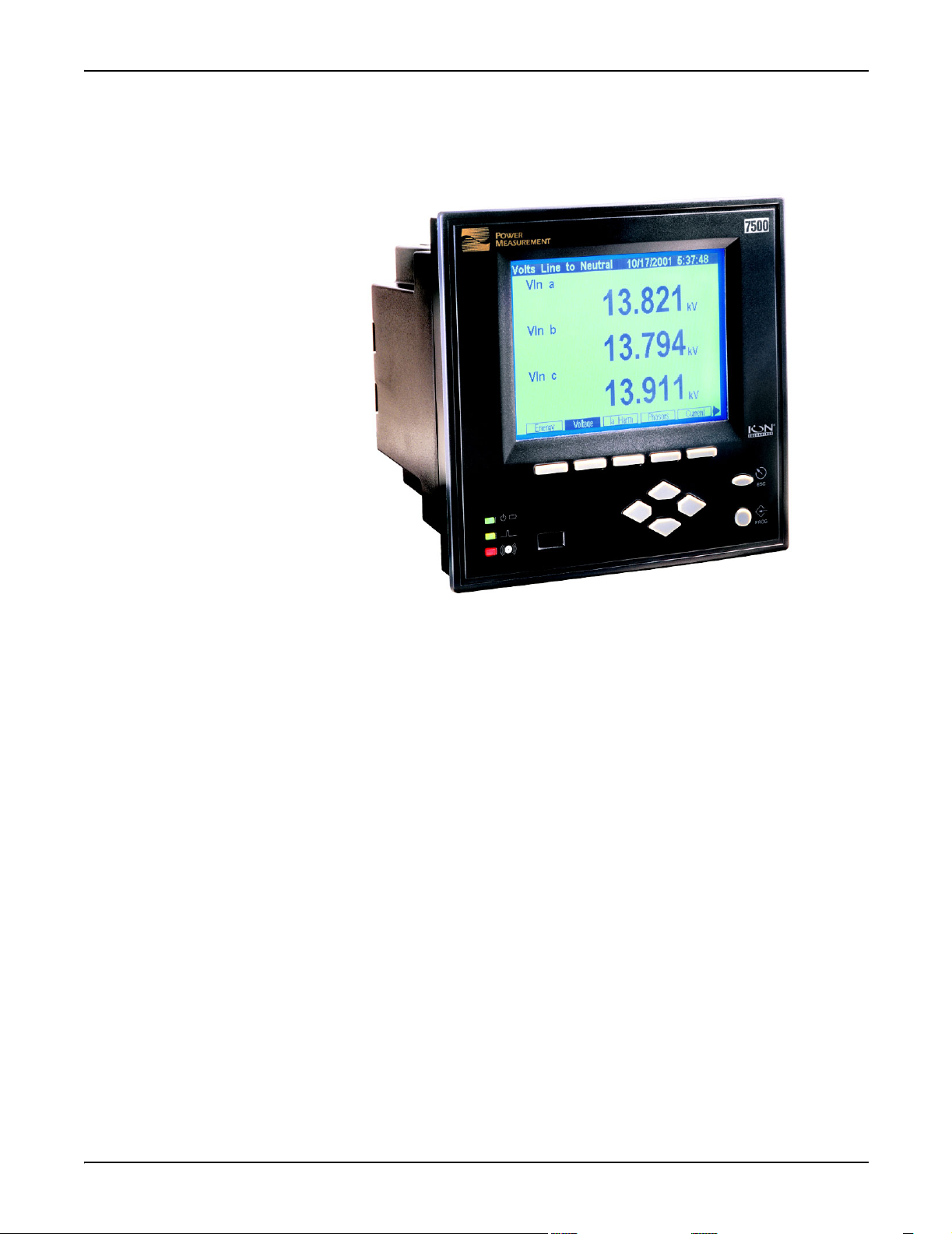
ION 7500™ and ION 7600™ intelligent metering and control devices provide
revenue-accurate, true RMS measurements of voltage, current, power and energy,
and are complemented by extensive I/O capabilities, comprehensive logging, and
advanced power quality measurement and compliance verification functions. The
meters come with an extensive selection of pre-configured data screens and
measurements, so you can use the meters “out of the box” or customize them to fit
your unique requirements.
ION 7500 and ION 7600 meters can replace numerous transducers, traditional
meters, and control circuits. You can integrate the meters with ION
other energy management, SCADA, automation and billing systems, via multiple
industry-standard communication channels and protocols.
®
software or
In This Chapter
◆ ION 7500 and ION 7600 Meters . . . . . . . . . . . . . . . . . . . . . . . . . . . . . . . . 12
◆ The ION meter in an Enterprise Energy Management System . . . . . . . . . . . 14
Data Display and Analysis Tools . . . . . . . . . . . . . . . . . . . . . . . . . . . . . . . . . . . . . . . 14
Communications Protocols . . . . . . . . . . . . . . . . . . . . . . . . . . . . . . . . . . . . . . . . . . . . . 16
Digital and Analog I/O Options . . . . . . . . . . . . . . . . . . . . . . . . . . . . . . . . . . . . . . . . . 16
The Meter is Factory-Configured and Ready to Operate . . . . . . . . . . . . . . . . . . . . 17
◆ Firmware Revision History . . . . . . . . . . . . . . . . . . . . . . . . . . . . . . . . . . . . . 18
◆ Using this Guide . . . . . . . . . . . . . . . . . . . . . . . . . . . . . . . . . . . . . . . . . . . . 19
Getting More Information . . . . . . . . . . . . . . . . . . . . . . . . . . . . . . . . . . . . . . . . . . . . . 19
Page 11
Page 12
ION 7500 and ION 7600 Meters ION 7500 / ION 7600 User’s Guide
ION 7500 and ION 7600 Meters
The ION 7500™
The ION 7500 and ION 7600 are intelligent metering and control devices suited to
a wide range of applications. The meters can be used as stand-alone devices, but
their extensive capabilities are fully realized when used with ION software, as part
of an enterprise energy management (EEM) system.
EEM systems give energy suppliers, service providers, and large industrial and
commercial energy consumers the tools to meet all the challenges and
opportunities of the new energy environment. EEM systems use real-time
information and control to directly address a broad range of requirements
throughout the power delivery chain and across an entire enterprise. These
systems offer an integrated solution to managing new billing structures,
distributed generation, energy purchasing, energy cost control, operational
efficiency, and power quality and reliability.
ION technology uniquely delivers the benefits of enterprise energy management
through an efficient, economical, and scalable architecture using web-enabled
software and intelligent metering and control devices. ION systems place
intelligence everywhere it’s needed, delivering information and control to
everyone that needs it, wherever they are. This gives all parties the necessary
information to make the best energy decisions, and the control to act on them.
Systems can span widely dispersed geographic locations and multiple points
within each site. A single, shared system delivers a broad range of functionality
that can satisfy the needs of many different groups within an enterprise, while
integrating seamlessly with existing systems.
Page 12 Chapter 1 - Introduction
Page 13

ION 7500 / ION 7600 User’s Guide ION 7500 and ION 7600 Meters
ION Enterprise™ is a powerful web-ready software suite that can process,
analyze, store, and share information from across your entire organization. Its
compatibility and flexibility means you can introduce individual components, at a
pace you decide, while maintaining your original investments. You can access
information and alarms from any workstation, pager, PDA, or cell phone locally or
around the world, in the format you require. You can also perform coordinated
load and equipment control functions, either manually or automatically. ION
software collects data automatically from ION meters and third-party devices, so
you can manage a single site or a global network of devices. ION software and
hardware products reduce cost of installation and ownership by leverage existing
corporate networks and popular networking technologies, including serial,
wireless, modem, Ethernet and Internet links.
A wide selection of ION intelligent metering and control devices are available,
with choices to meet the specific needs of various key points within an enterprise.
Devices offer a range of high accuracy metering, power quality and reliability
analysis, data and event logging, alarming, control and communications.
This manual discusses ION 7500 and ION 7600 meter default functionality, as well
as features and applications. Throughout the manual, the term “meter” refers to
both meter models. All differences between the models, such as a feature specific
to one model, are indicated with the appropriate model number.
These meters can be used effectively in numerous energy supply-side (utility) and
demand-side applications. Some common meter applications are:
◆ Revenue metering
◆ Substation automation
◆ Power quality monitoring (with Flicker)
◆ Commercial/industrial operations metering
◆ Demand and power factor control
◆ SCADA (supervisory control and data acquisition)
◆ Distributed generation (generator) monitoring and control
Chapter 1 - Introduction Page 13
Page 14
The ION meter in an Enterprise Energy Management System ION 7500 / ION 7600 User’s Guide
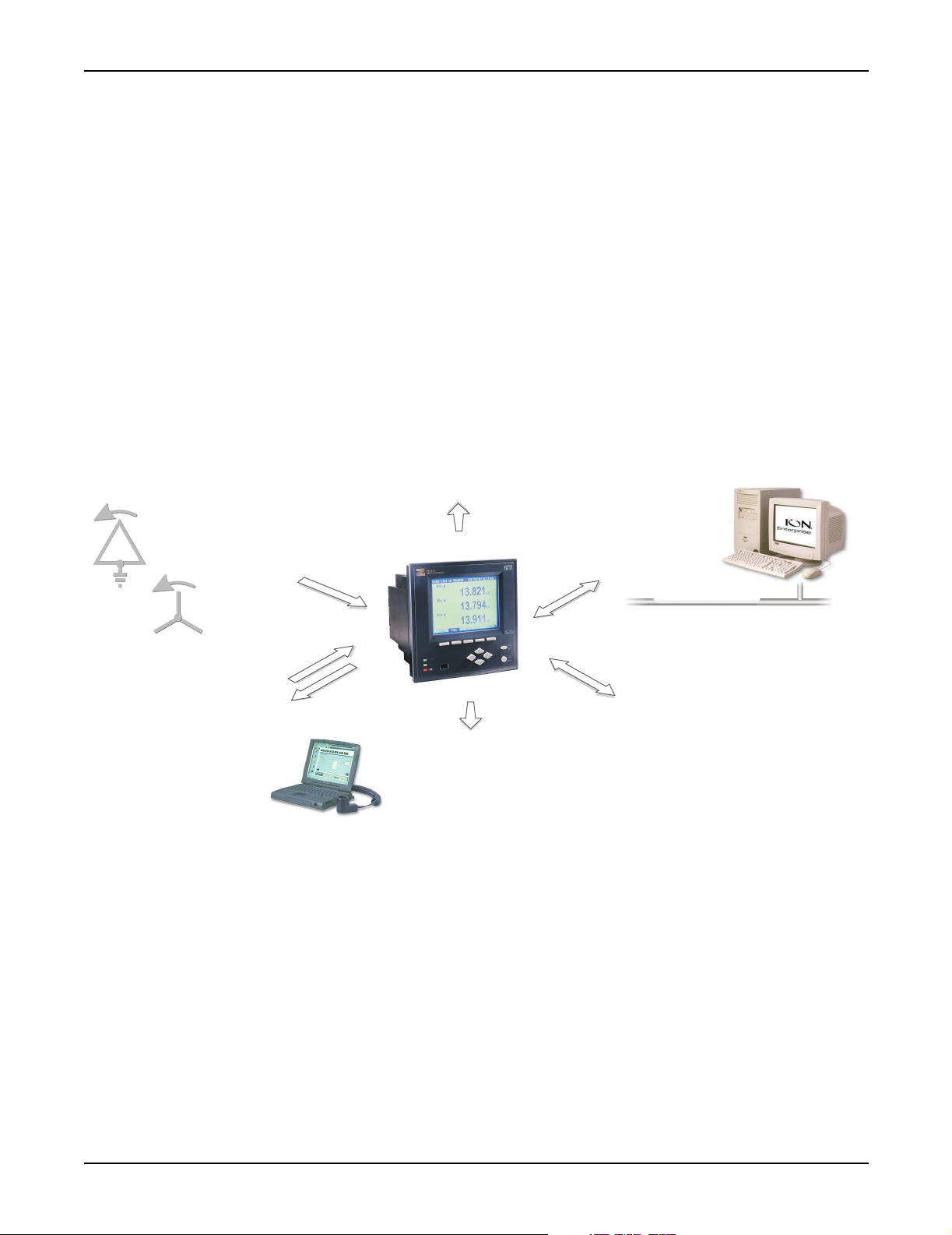
The ION meter in an Enterprise Energy Management System
Applications that include the meter typically require additional equipment.
Display and analysis software tools are almost always used to manage, interpret
and distribute the data measured or logged by a meter. There are usually a variety
of tools used, and often these tools are connected using different communications
standards and protocols. In many cases, a meter must also provide control
capabilities and device-level data sharing.
The meter can adapt to many situations. Advanced communications allow data to
be shared simultaneously across multiple networks, built-in I/O provides
monitoring and control capabilities, and a variety of display and analysis tools can
be used to monitor your power system.
Internet Connectivity
- MeterM@il
- WebMeter functionality
- XML compatibility
Power System Connections
Phase voltage, phase current, ground current,
and neutral current from Wye, Delta, or
N
single-phase power systems
N
N
Onboard I/O
-
Pulses
Breaker Status
-
Control Signals
-
Energy Pulses
On-Site Data Display
- 320 by 240 pixel LCD
Remote Data Display
Vista
-
WebReach
-
Data Display and Analysis Tools
Not only does the meter’s front panel allow meter configuration and data display,
but the meter also integrates seamlessly with display and analysis software
available from Power Measurement. ION Enterprise software is the network and
device configuration software that also lets you analyze and monitor your system
and produce reports for any department in an organization. Furthermore, you can
use data acquired by the meter in a variety of third-party systems. ION software is
designed to make use of all the available advanced capabilities.
Data Analysis Tools
-
Power Monitoring Network
Third-Party Software for
-
Modbus, DNP 3.00, Mv90
Corporate Network
Communications
-
RS-232 and high speed RS-485
Internal Modem
-
-
Optical infrared
10 Base-T and 10 Base-FL Ethernet
-
Interoperability
-
Protocols: ION, Modbus Master, Modbus RTU,
-
Modbus TCP,
to RS-485 gateway), EtherGate (Ethernet
to RS-485 gateway), GPS: Arbiter,
GPS:True Time/Datum
DNP 3.00, ModemGate (modem
Page 14 Chapter 1 - Introduction
Page 15

ION 7500 / ION 7600 User’s Guide Data Display and Analysis Tools
The Front Panel
Local monitoring and standalone applications are facilitated by the meter’s front
panel interface. The front panel combines real-time display features with limited
device configuration functions.
The front panel is often used in combination with an ION software system,
providing an interface for field personnel.
WebMeter® Embedded Web Server Feature
An on-board web server combined with an Ethernet port provides quick and easy
access to real-time energy and basic power quality information without special
software: this is WebMeter functionality. The built-in web pages display a range of
energy and basic power quality information through the web-enabled device;
these pages even support basic meter configuration tasks.
MeterM@il® Internal E-Mail Server Feature
Configure the meter to automatically email high-priority alarm notifications or
scheduled system-status update messages to anyone, anywhere within the facility
or around the world. Specify the type of event that triggers an email alert, such as
power quality disturbances or logged data at any pre-determined interval, and
have your ION software administrator program the meter to respond with a
MeterM@il message when these events occur. MeterM@il messages can be
received like any email message over a workstation, cell phone, pager, or PDA.
XML Compatibility
The meters can exchange information using industry-standard XML format. This
simple machine-readable format supports easy integration with custom reporting,
spreadsheet, database, and other applications.
ION Enterprise™ Software
The complete ION Enterprise software package enables the meter to be part of a
fully networked information system with other meters and local and wide-area
computer networks. ION Enterprise is recommended for all power monitoring
systems where advanced analysis and control capabilities are required.
ION Enterprise provides tools for managing your power monitoring network,
logging data, analyzing real-time and logged data, generating power system
reports, and creating custom functionality at the meter level.
ION Enterprise also offers two ways to remotely view information through a web
browser: WebReach and Microsoft Terminal Services.
◆ WebReach only requires an URL to display a meter’s real-time data and select
views of historical and waveform data from a web browser; there is no client
machine configuration. WebReach is a data display application; there is no
control functionality available through it.
◆ Microsoft Terminal Services enable full ION Enterprise functionality, including
control features. Some client machine configuration is required.
Chapter 1 - Introduction Page 15
Page 16

Communications Protocols ION 7500 / ION 7600 User’s Guide
ION Setup™ Software
ION Setup is a meter configuration tool designed specifically to configure and test
meters. ION Setup offers an intuitive graphical interface for performing basic
meter setup, installing templates into meters, viewing real-time and reset
accumulated values, verifying meter calibration and measurements, and setting
up advanced security.
Communications Protocols
The meter can be integrated into various industry-standard networks. Data that is
measured by the meter can be made available to other devices using the Modbus
Master, Modbus RTU, Modbus TCP, and DNP 3.00 protocols, as well the MV-90
translation system. You can also configure the meter to import data from devices
on these networks. With these advanced communications functions, the power of
the meter can be utilized in most existing power monitoring systems. Any data
display and analysis software that works with Modbus RTU or DNP 3.00 devices
will also function with the meter.
The standard meter includes a selectable RS-232/RS-485 port (the factory default is
RS-232), a high-speed RS-485 port, and an IrDA optical port for communications
in the field. Order options include a 10Base-T Ethernet port or 10Base-FL fiberoptic port, and a 33.6 kbps internal modem (both FCC and CTR-21 compliant).
Depending on the hardware options purchased, up to four separate ports can
communicate simultaneously.
The communications card is retrofittable – it can be replaced while the meter is in
the field.
Digital and Analog I/O Options
The meter has digital inputs and outputs that connect to the captured-wire
terminals near the base of the unit. Additionally, a LED on the front panel is
configured for energy pulsing. An optional analog I/O card can also be ordered
with your meter. There are retrofit instructions for this I/O card, if you desire the
card on a previously purchased meter.
Digital Inputs
The meter contains eight self-excited digital inputs capable of detecting a pulse
rate of 20 pulses/second and timestamping transitions with 1ms resolution. They
can be used for monitoring external contacts or pulse counting applications. These
inputs use a current sensing technique to monitor contact status by providing an
internal 30 VDC supply for self-excitation.
Relay Outputs
The meter contains four solid-state Form A outputs and three mechanical Form C
relays. The solid-state outputs have a maximum voltage rating of 30 VDC and
maximum current rating of 100 mA. The mechanical relays are rated at 250 VAC /
30 VDC and can switch up to 10A loads.
Page 16 Chapter 1 - Introduction
Page 17

ION 7500 / ION 7600 User’s Guide The Meter is Factory-Configured and Ready to Operate
Analog Inputs and Analog Outputs
The meter offers an optional Analog I/O expansion card with numerous options:
◆ four 0 to 1 mA analog inputs
◆ four 0 to 20 mA analog inputs
◆ four -1 to 1 mA analog outputs
◆ four 0 to 20 mA analog outputs
◆ four 0 to 20 mA analog inputs & four 0 to 20 mA outputs
◆ four 0 to 1 analog inputs and four -1 to 1 mA analog outputs
NOTE
All options have an additional eight digital inputs on the card.
The Meter is Factory-Configured and Ready to Operate
Even though the meter is fully customizable, it is shipped from the factory with
many pre-configured functions. Once you have performed the installation and
basic setup, all of the basic measurements, energy calculations and recording
functions are ready to operate right out of the box. You may find that the factory
configuration aptly serves your purposes, allowing you to forego additional
configuration.
Chapter 1 - Introduction Page 17
Page 18
Firmware Revision History ION 7500 / ION 7600 User’s Guide
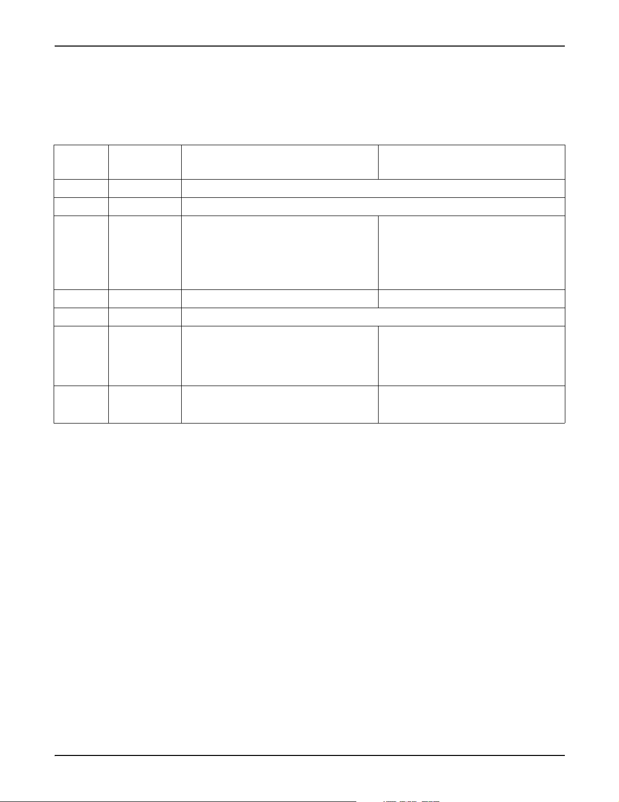
Firmware Revision History
The table below lists the features related to a particular firmware release for your
meter.
Firmware
Version
Release Date Firmware Enhancements Template Improvements
v201 Aug. 10, 2000
v203 Apr. 14, 2000
v206 Jan. 12, 2001
v207 Feb. 22, 2001
v210 May 16, 2001
v222 Nov. 28, 2001
v231 Aug. 6, 2002
◆ Initial release of the ION 7600 meter
◆ Implemented the ModemGate protocol
◆ Analog I/O
◆ WebMeter
◆ MeterM@il
◆ new and enhanced ION Modules
◆ Hardware improvements:
1 Amp current input option,
Modicon Modbus TCP communications
◆ Tre n d i n g D i s p l ay featur e ◆ New Trend Display Module
◆ NICT and TRAN support added
◆ Modbus Master capability
◆ DNP enhancements
◆ Hardware improvements:
Option to order ION 7500 with 4 MB or 8 MB of Log
Memory
◆ Internet Phase 2
◆ Stack replacement
◆ Hardware improvements
◆ Revenue Log Module enhancements
◆ Sag/Swell Events on V4
◆ Number of Nines display screen
◆ 9 additional DNP Slave modules
◆ 4 additional Calibration Pulser modules
◆ The maximum allowable number of the following ION
Modules has been increased (see addendum for
actual numbers):
◆ Integrator, Data Recorder, Sliding Window Demand,
External Boolean, Minimum, Maximum, Display, Set
Point
◆ Log Mail module replaced by the Log Export module
◆ New Web Page module
Page 18 Chapter 1 - Introduction
Page 19

ION 7500 / ION 7600 User’s Guide Using this Guide
Using this Guide
This User’s Guide is directed at three types of user: the typical user or operator, the
system administrator, and the advanced user. You might not fit into any of these
groups directly, or perhaps you are both an operator and an administrator. These
classifications are intended to make this guide easier to navigate with respect to
which information is appropriate to your needs.
Typical User or Operator
Most users simply want to display the data provided by the factory-configured
meter. These users want fast access to data through the front panel, ION software,
or a third-party protocol such as Modbus or DNP.
System Administrator or Manager
Some users need to make minor adjustments so that their meters “fit” their power
systems: data recording intervals, demand sub-intervals and other parameters
may need to be set before the meter’s setup is complete. These users will use the
front panel, or ION software to change settings in the device’s operating software.
(ION Enterprise is highly recommended.)
Advanced User or Systems Integrator
Advanced users may want to make use of the flexibility and power provided by
the device’s operating software. These users will need to become familiar with the
ION architecture, and the ION software tools used to customize the device’s
operation.
Before You Can Use this Guide
By the time you are ready to use this guide, your meter should be installed, basic
setup should have been performed, and communications/basic operation should
have been verified. If the unit is not yet installed and operational, refer to the
Installation & Basic Setup Instructions shipped with the meter.
Getting More Information
Additional information is available from Power Measurement. Check our web site
at www.pwrm.com, contact your local Power Measurement representative, or
contact Power Measurement directly (contact information is provided on the first
page of this document). Documents that are related to the installation, operation
and application of the meter are as follows:
Installation & Basic Setup Instructions
This brief guide is shipped with each meter. It details the mounting, wiring and
basic setup of the device.
ION Programmer’s Reference
This online reference contains detailed descriptions of all modules in an ION
meter.
Chapter 1 - Introduction Page 19
Page 20

Getting More Information ION 7500 / ION 7600 User’s Guide
ION Enterprise Administrator Guide
This guide explains the installation and configuration of the ION Enterprise
software suite.
Online ION Enterprise Help
Each ION Enterprise software component has an in-depth online help system.
Technical Notes
Appendix A contains technical notes that provide details for meter features and
custom configurations. These technical notes are also available from our website
which is regularly updated with new and revised technical notes.
Application Notes
Online application notes offer detailed, high-level descriptions of real-world
situations, where Power Measurement’s ION devices and ION software provide
beneficial solutions.
Page 20 Chapter 1 - Introduction
Page 21

CHAPTER
. . . . . . . . . . . . . . . . . . .
2 Using The Front Panel
The meter’s front panel is used for both display and configuration purposes. The
liquid crystal display (LCD) screen and the numerous selection, navigation, and
configuration buttons allow quick access to basic meter configuration provided by
special setup screens. The front panel also provides access to the settings of many
other meter functions. Although you can customize the type of data you want
displayed, this cannot be done through the meter’s front panel.
In This Chapter
Displaying Data with the Front Panel . . . . . . . . . . . . . . . . . . . . . . . . . . . . . 22
Display Screen Types . . . . . . . . . . . . . . . . . . . . . . . . . . . . . . . . . . . . . . . . . . . . . . . . . 23
Default Front Panel Display Screens . . . . . . . . . . . . . . . . . . . . . . . . . . . . . . . . . . . . . 26
Configuring the Meter with the Front Panel . . . . . . . . . . . . . . . . . . . . . . . . 31
The Front Panel’s Setup Menu . . . . . . . . . . . . . . . . . . . . . . . . . . . . . . . . . . . . . . . . . . 31
Basic Setup Menu . . . . . . . . . . . . . . . . . . . . . . . . . . . . . . . . . . . . . . . . . . . . . . . . . . . . . 33
Main Setup Menu . . . . . . . . . . . . . . . . . . . . . . . . . . . . . . . . . . . . . . . . . . . . . . . . . . . . . 34
Demand Setup Menu . . . . . . . . . . . . . . . . . . . . . . . . . . . . . . . . . . . . . . . . . . . . . . . . . . 34
Network Setup . . . . . . . . . . . . . . . . . . . . . . . . . . . . . . . . . . . . . . . . . . . . . . . . . . . . . . . 36
Serial Communications Setup . . . . . . . . . . . . . . . . . . . . . . . . . . . . . . . . . . . . . . . . . . 38
PQ (Power Quality) Setup . . . . . . . . . . . . . . . . . . . . . . . . . . . . . . . . . . . . . . . . . . . . . 39
Format Setup Menu . . . . . . . . . . . . . . . . . . . . . . . . . . . . . . . . . . . . . . . . . . . . . . . . . . . 40
Display Setup Menu . . . . . . . . . . . . . . . . . . . . . . . . . . . . . . . . . . . . . . . . . . . . . . . . . . 41
Time Setup Menu . . . . . . . . . . . . . . . . . . . . . . . . . . . . . . . . . . . . . . . . . . . . . . . . . . . . . 41
Meter Resets . . . . . . . . . . . . . . . . . . . . . . . . . . . . . . . . . . . . . . . . . . . . . . . . . . . . . . . . . 43
Security Setup . . . . . . . . . . . . . . . . . . . . . . . . . . . . . . . . . . . . . . . . . . . . . . . . . . . . . . . . 44
Custom Front Panel Displays . . . . . . . . . . . . . . . . . . . . . . . . . . . . . . . . . . . 46
Creating a Front Panel Reset . . . . . . . . . . . . . . . . . . . . . . . . . . . . . . . . . . . . . . . . . . . 46
Page 21
Page 22
Displaying Data with the Front Panel ION 7500 / ION 7600 User’s Guide
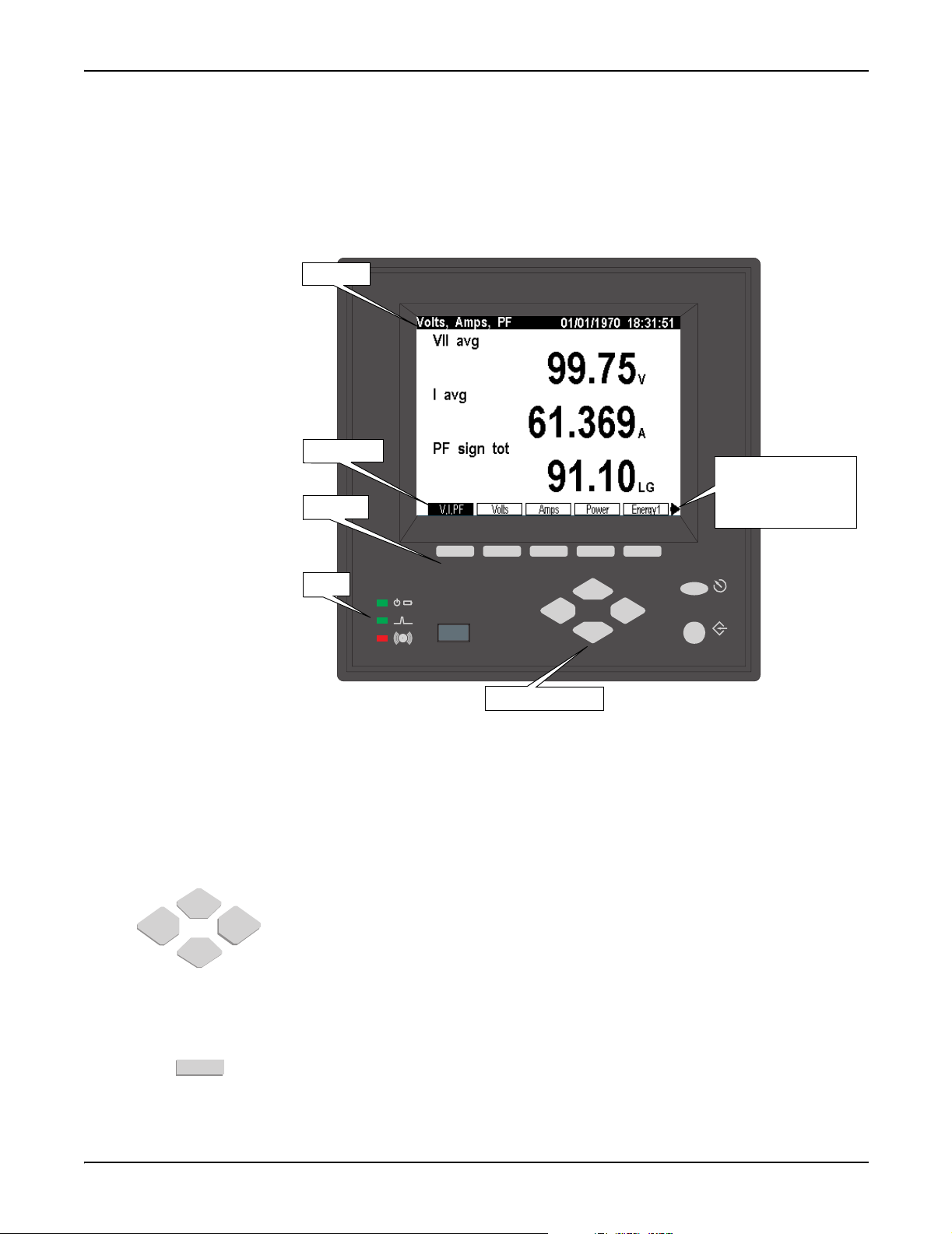
Displaying Data with the Front Panel
The front panel LCD (liquid crystal display) provides a detailed graphics and text
display that has been factory configured to show many of the parameters
measured by the meter.
Status Bar
Softkey Titles
The arrow indicates
that another group of
Softkeys
screens is available on
the left.
LEDs
Navigation buttons
ESC
PROG
The meter’s display can show numeric data screens, event logs, phasor diagrams,
bar graphs, and harmonics histograms.
Using the Front Panel Buttons to Display Data
The front panel has numerous buttons: softkeys, navigation buttons, program
buttons. Program buttons are used when configuring the meter (see page 32). Use
the following buttons to view data on the front panel display screens.
Navigation Buttons
The horizontal navigation buttons (Left/Right keys) select a different set of five
Softkey titles to access different data screens. The vertical navigation buttons
(Up/Down keys) are used to navigate within certain data display screens, such as
within a Trend Display’s graph and log screens or an Event Log screen, once one
has been selected.
Softkeys
A Softkey button selects the data screen available in the corresponding Softkey title
when pressed.
Page 22 Chapter 2 - Using The Front Panel
Page 23
ION 7500 / ION 7600 User’s Guide Display Screen Types
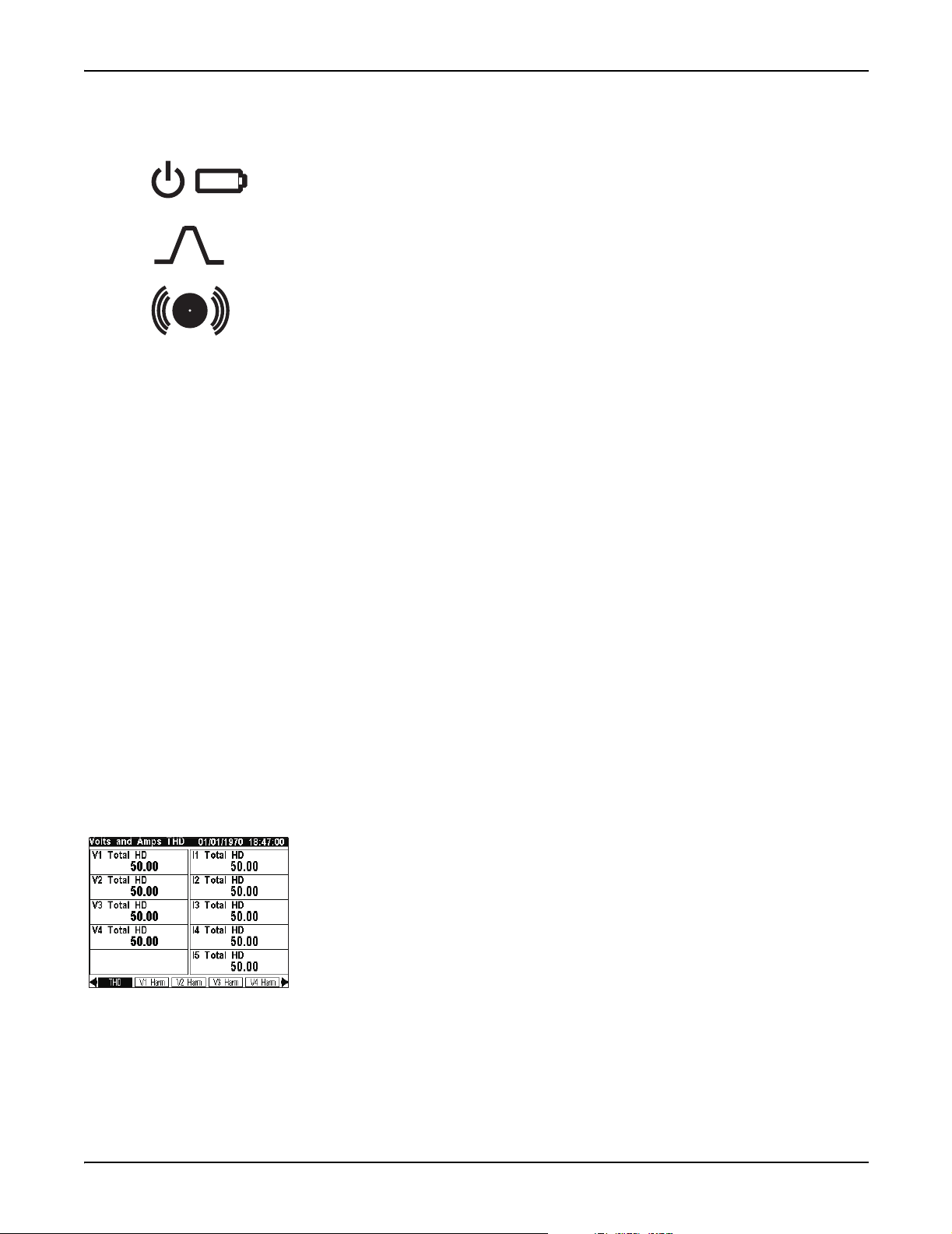
Front Panel LEDs
The front panel LEDs are as follows:
The green operation LED (top) should always be on when the meter is in
service. Contact Technical Services if this is not the case.
The green LED in the middle is factory configured to be a Wh (del+rec) pulser.
During the course of normal operation, this LED should blink intermittently as
the meter measures power system energy.
The red LED (bottom) on the front panel of the meter is provided for custom
applications. Possible applications include sag/swell alarming, setpoint
annunciation, and tariff notification. Like all the other outputs on the meter, this
port can be controlled by a Digital Output, Pulser, or Calibration Pulser module.
Backlight Operation and Display Contrast
The front panel display is factory configured to dim five minutes after the last
button press.If the front panel is dimmed, press any button to return the LCD to
full brightness. The front panel display is adjusted at the factory to the optimal
contrast level. If the contrast needs adjusting or want to change the backlight timeout period, you can do so from the Display Setup menu (see page 41).
Status Bar
The Status Bar of the meter is located along the top of all display screens. When in
data display mode, the Status Bar shows: the date in MM/DD/YYYY format
(configurable), the current local time in 24 hour format, and the data display screen
title.
Display Screen Types
The meter’s front panel displays measurements, configurable settings, and current
configuration data in various forms. These data display screens are described
below. Configuration (Setup menu) displays are described in the chapter "Default
Functionality."
Numeric Displays
Numeric displays can show multiple parameters at a time: two, three, three with a
timestamp, four, eight, ten (shown), or twenty. When displaying numeric values
for current and power quantities, the front panel shows resolution to three decimal
places by default. All other values are displayed to two decimals of accuracy. If
you want to see finer resolutions, use Vista software to display the data.
If the front panel is unable to read a numeric value, or if the value is not available,
it displays a dash (—).
Chapter 2 - Using The Front Panel Page 23
Page 24
Display Screen Types ION 7500 / ION 7600 User’s Guide
Automatic Units
The front panel automatically scales the units for basic measurements, such as
voltage, current and power parameters. For example, a measurement of 2,000
Watts is displayed as 2.000 kW. A measurement of 2,000,000 Watts is displayed as
2.000 MW. The meter makes these conversions using your PT and CT ratios.
The meter only performs these automatic units if the measurement is derived
solely from the Power Meter module’s output.
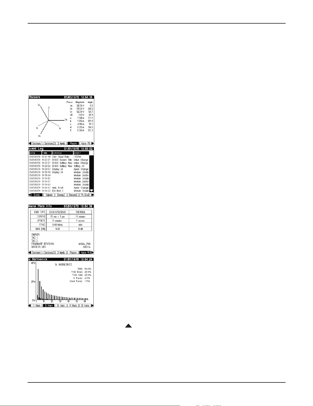
Phasor Diagram Displays
Phase information can be displayed in phasor diagram format. Phasor diagrams
are accompanied by tables that state the angle and magnitude of each phasor.
In cases where phasors are too small to be represented graphically, they are only
shown as table entries.
Event Log Displays
Event Log displays alert you to recent events written to the meter’s event log. The
vertical (Up/Down) navigation buttons are used to move through the list.
Details on altering the meter’s Event Log characteristics, such as log depth and
logging frequency, using Designer can be found in the "Default Functionality"
chapter.
Nameplate Displays
Like Event Log displays, Nameplate displays show information in tabular format.
Default nameplates show owner, meter, and power system details.
See the section "Time-Of-Use Configuration" in the Default Meter Functionality
chapter for details on configuring the T
AG strings.
Histogram Displays
Harmonics content is displayed in histogram format. Harmonics are displayed
from the 2
displayed above the histogram (K Factor and Crest Factor only appear in current
harmonic histograms).
Use the vertical navigation buttons on the meter front panel to select individual
harmonics (from 2
them (V
An arrow appears below the harmonic selected. Harmonic magnitude is
displayed as an absolute value and as a percentage of the fundamental. The phase
angle of each harmonic is also provided. To return to the THD values, position the
arrow below the fundamental.
nd
to the 63rd harmonic, with Total Harmonic Distortion (THD) values
nd
to 40th) in the histogram and view data specific to each of
, V2, V3, I1, I2, and I3 only).
1
Page 24 Chapter 2 - Using The Front Panel
Page 25
ION 7500 / ION 7600 User’s Guide Display Screen Types
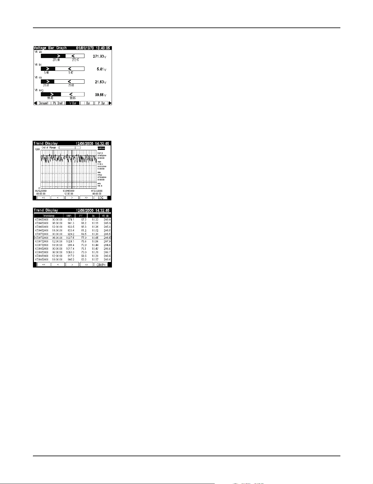
Trend Bar Graph Displays
Bar graph displays can show up to four real-time (numeric) parameters along with
their upper and lower extremes.
Each bar graph automatically scales its output based on the magnitude of its
extremes. The real-time value of each bar graph is displayed to the right of the
graph. Note that scaling is applied separately to each bar graph in the display. Do
not compare the magnitudes of two values based on the size of their bars.
In the trend bar graph shown on the left, the present value of Vll ab is 271.93 V. The
bar graph also indicates that it has gone as low as 271.40 V and as high as 272.47 V.
Trend Displays
The Trend Display screen graphs the historical data of up to four different
parameters simultaneously. A movable cursor that consists of the intersection of a
vertical line and a horizontal line displays the value and timestamp of any plotted
data within a parameter. The cursor displays the values of one parameter at one
time only. With the Up and Down navigation keys, the cursor can move from one
parameter to another.
In addition, a Trend Display log screen displays data logs for any graphed
parameter – up to 3360 logs for each parameter. That is equivalent to 35 days worth
of 15 minute data. The graph is updated when a new set of values is recorded. The
highest supported update speed is once per second.
The ION 7500 front panel displays three preconfigured trending screens: V-Trend
(voltage), I-Trend (current), and P-Trend (power). The ION 7600 must be
configured using Designer in order to provide Trend Display. Contact Technical
Services if you require your ION 7600 to be configured for Trend Display.
Chapter 2 - Using The Front Panel Page 25
Page 26

Default Front Panel Display Screens ION 7500 / ION 7600 User’s Guide
Default Front Panel Display Screens
The meter is factory configured to display a number of data screens on its front
panel:
42 display screens for the ION 7500
48 display screens for the ION 7600
Each of these screens is accessible with a corresponding Softkey. See the “Button
Functions” section for instructions on using the front panel buttons for data
display.
NOTE
Each display screen is listed with the corresponding softkey name and the screen title.
Screens Shown in Display Cycle
Ten data display screens are included in the automatic display cycle. By default,
the front panel scrolls repeatedly through the following screens in the order
presented.
For details on screen type (e.g. three parameter, vector diagram, etc.) refer to the
technical note Custom Front Panel Displays.
1. V,I,PF (Volts, Amps, PF)
This numeric display screen contains the average line-to-line voltage, average
current, and the total signed power factor.
2. Volts (Volts)
This numeric display screen shows the line-to-line voltages Vll ab, Vll bc, and
Vll ca.
3. Amps (Amps)
This is a numeric screen containing currents I a, I b, and I c.
4. Power (Total Power)
This numeric display screen contains total kW, kVAR, and kVA values.
5. Energy1 (Energy Delivered)
This numeric display screen shows delivered (imported) energy values for kWh,
kVARh, and kVAh.
6. Demand1 (Demand Delivered)
This numeric display screen contains delivered values (kW, kVAR, and kVA) in
the previous demand period. By default, these values come from a sliding
window demand (rolling block) calculation.
Page 26 Chapter 2 - Using The Front Panel
Page 27

ION 7500 / ION 7600 User’s Guide Default Front Panel Display Screens
7. Pk Dmd1 (Peak Demand Del)
This is a numeric display screen with timestamps that contains maximum
delivered demand values for kW, kVAR, and kVA. The timestamps show the
date and time at which the values were last updated. By default, these values
come from a sliding window demand calculation.
8, 9, 10. V Bar, I Bar, P Bar (Voltage, Current, and Power Bar Graphs)
These three screens are trend bar graph displays. They show real time values for
voltage (Vll ab, Vll bc, Vll ca, Vll avg), current (I a, I b, I c, I avg) and
power (kW tot, kVAR tot, kVA tot, PF lag tot). The bar graphs also indicate the
maximums and minimums recorded for these values.
Additional Data Display Screens
Most of the default data screens are not included in the default scrolling cycle. To
view the other display screens, you must find the group of five Softkey titles that
contains the data screen you want, and then press the corresponding Softkey.
NOTE
The numbers on the left correspond to the Display module’s Softkey number in the ION 7600 meter’s
display framework. The Softkey numbering for an ION 7500 differs slightly due to V trend, I trend, and
P trend taking the place of Softkeys 13, 14, and 15 respectively. The ION 7500 does not support display
screens for EN50160 data and statistics.
11. Summary1 (Volts/Amps Summary)
This numeric display provides many important voltage, current, phase, and
frequency measurements on a single screen.
12. Summary2 (Power Summary)
This numeric display provides real, reactive, and apparent power
measurements for phase a, b and c (as well as their total). Signed Power Factor
measurements are also provided on this screen.
13. D Inputs (Digital Inputs)
This numeric display screen shows the status of the eight on-board digital
inputs. The present state of all inputs is shown (as Off or On) and the number
(Cnt) of state changes since the last reset is recorded.
14. DI - I/O (DI on I/O Card)
This numeric display screen contains the status and counters for the digital
inputs on the I/O card.
15. D Outputs (Digital Outputs)
This numeric display screen contains the mode and status for the relay and solid
state outputs.
16. Anlg - I/O (Analog In and Out)
This numeric display screen contains scaled analog inputs (AIn scaled) and
normalized analog outputs (AOn normalized), where n ranges from 1 to 4 for
both inputs and outputs.
Chapter 2 - Using The Front Panel Page 27
Page 28

Default Front Panel Display Screens ION 7500 / ION 7600 User’s Guide
17. Phasors (Phasors)
This screen is a phasor diagram display that shows the magnitude and the
relative angular difference between all phase voltage (V a, V b, V c, V 4) and
current (I a, I b, I c, I 4, I 5) fundamental components.
18. Name Plt (Name Plate Info)
The Name Plate Info screen contains the following information: Owner,
and
TAG 2 from the Factory module, firmware revision of the ION meter, and a
battery life indicator.
installed location. The Owner and
TAG 1 and TAG 2 typically identify the meter’s user and
TAG registers are configurable with the
Designer software.
19. Events (Event Log)
The Event Log display alerts you to events written to the meter’s event log.
D
ATE, TIME, SOURCE, and EVENT information are provided. The up and down
Navigation buttons allow you to move through the list.
20. Setpoint (Setpoint Status)
This numeric display screen displays the status of the setpoint parameters
defined in the Vista Setpoints diagram.
21. Energy2 (Energy Received)
This numeric display screen shows received (exported) energy values for kWh,
kVARh, and kVAh.
22. Demand2 (Demand Received)
This numeric display screen shows received power quantities (kW, kVAR, and
kVA) in the present demand period. By default, these values are from a sliding
window demand (rolling block) calculation.
23. Pk Dmd2 (Peak Demand Rec)
TAG 1
This is a numeric display screen with timestamps. It shows the maximum
received demand quantities (kW, kVAR, and kVA) and the time at which they
were recorded. By default, these values are from a sliding window demand
(rolling block) calculation.
24. THD (Volts and Amps THD)
This numeric display screen contains the total harmonic distortion on all phase
voltage and current inputs.
25, 26, 27, 28. V1 Harm, V2 Harm, V3 Harm, V4 Harm (Harmonics)
These four histogram display screens show the harmonic content on the phase
voltage inputs.
29, 30, 31, 32, 33. I1 Harm, I2 Harm, I3 Harm, I4 Harm, I5 Harm (Harmonics)
These five histogram display screens show the harmonic content on the phase
current inputs.
34. TOU (Active Rate / Season)
This eight parameter display screen shows kWh delivered values for each all
four of the possible time of use (TOU) rates (rates A, B, C, and D).
Page 28 Chapter 2 - Using The Front Panel
Page 29

ION 7500 / ION 7600 User’s Guide Default Front Panel Display Screens
35. TOU Egy (TOU Energy Del)
This numeric display screen shows the energy (in kWh) delivered for each time
of use (TOU) rate (rates A, B, C, and D).
36, 37. TOU Dmd1 & TOU Dmd2 (TOU Peak Demand 1 and 2)
These two screens are numeric displays with timestamps. Together they show
the maximum delivered kilowatts for each time of use (TOU) rate (rates A, B, C,
and D). The timestamps show the date and time at which the values were last
updated. By default, these values come from a sliding window demand (rolling
block) calculation.
NOTE
The four TOU screens may only be important if you are using the meter in a billing application (i.e. you
are a power provider). Typically, power consumers ignore the Time-Of-Use front panel displays.
EN50160 Data and Statistics Displays (ION 7600 only)
The remaining front panel screens display data to help you determine EN50160
voltage compliance. Unless compliance to this standard is of concern, you may
ignore these displays. More details about EN50160 are provided in the technical
note Power Quality: ION Meters and EN50160.
38. PQ Freq (PQ Power Frequency)
This numeric display shows the following EN50160 Power Frequency data:
Nominal Frequency, period (10 second) Freq mean, minimum, and maximum.
It also shows the EN50160 frequency compliance statistics: Freq N (the number
of valid evaluation periods), Freq N
(a count of non-compliance), and Freq N2
1
(the number of invalid evaluation periods).
39. PQ Vmag1 (PQ Supply Voltage 1)
This bar graph display shows the following EN50160 Voltage Magnitude data
for all three voltage phases: period (10 minute) mean, minimum, and maximum.
40. PQ Vmag2 (PQ Supply Voltage 2)
This numeric display shows the following EN50160 Voltage Magnitude
compliance statistics for all three voltage phases: mag N and mag N1.
41. PQ Flk1 (PQ Flicker 1)
This bar graph display shows the following EN50160 Flicker data for all three
voltage phases: present Pst, minimum Pst, and maximum Pst.
42. PQ Flk2 (PQ Flicker 2)
This numeric display shows the following EN50160 Flicker data for all three
voltage phases: present Pst, present Plt, and compliance statistics (Flck N and
Flck N
).
1
43. PQ Vdist (PQ Volt Disturbance)
This numeric display shows the following EN50160 Overvoltage and Dip data
for all three voltage phases: expected nominal, minimum Dip, and maximum
Overvoltage.
Chapter 2 - Using The Front Panel Page 29
Page 30

Default Front Panel Display Screens ION 7500 / ION 7600 User’s Guide
44. PQ Vunb (PQ Volt Unbalance)
This numeric display contains the following EN50160 Voltage Unbalance data:
V unbal mean, V unbal mean min, V unbal mean max, and compliance
indicators (unbal N and unbal N
).
1
45. PQ Vhrm1 (PQ Volt Harmonics 1)
This bar graph display shows the following EN50160 Harmonics data: THD
mean, THD mean mn, THD mean max for all three voltage phases (10-minute
mean values, min and max values are updated every new observation period).
46. PQ Vhrm2 (PQ Volt Harmonics 2)
This numeric display shows EN50160 Harmonics compliance statistics for all
three voltage phases: Hrm N, Hrm N
, Hrm N2.
1
47. Avblty (Power Availability)
This numeric display provides the following measurements: availability (with
up-time in parts per million), number of nines, and evaluation time (in days).
48. Pr - Avblty (Previous Availability)
This three parameter display with timestamp indicates the number of
availability resets (including the most recent event’s timestamp), the previous
availability (with its timestamp), and the previous number of nines (with its
timestamp).
Trending Display Screens in the ION 7500
The ION 7500 meter supports trending display in its framework. Each trending
display has two views - graph and log - which are accessible via softkey once you
are displaying the trend screen. As previously mentioned, the softkey numbering
for an ION 7500 meter’s display screens must be adjusted from the numbering
presented for the ION 7600
V Trend (Voltage Trend Display)
The voltage trend display graphs the VII avg trend. This display is Softkey 13.
I Trend (Current Trend Display)
The current trend display graphs the I avg trend. This display is accessed with
Softkey 14.
P Trend (Power Trend Display)
The power trend display graphs the KW tot trend. This display is accessed with
Softkey 15.
Page 30 Chapter 2 - Using The Front Panel
Page 31

ION 7500 / ION 7600 User’s Guide Configuring the Meter with the Front Panel
Configuring the Meter with the Front Panel
The front panel allows you to setup and configure the meter at its installed
location. When you change a setting in the front panel’s Setup menu, you are
actually altering the setup register value of an ION module. (ION module links
cannot be added or deleted using the front panel.) The front panel’s Setup menu
also provides you with quick access to parameter resets for common cumulative
parameters.
The Front Panel’s Setup Menu
To access the Front Panel’s Setup Menu, press that PROG (programming) button.
Pressing the
Each time you enter programming mode, the front panel
helps you keep track of your configuration changes by
marking the Setup menu (and sub-menu) items that you
have accessed. These check-marks are cleared when you
exit programming mode.
ESC (escape) button returns you to the data display screens.
Use the Softkey buttons
to make choices when
Softkey titles appear
above them.
Use the Navigation buttons
to select (highlight) choices
and enter numerical data.
The arrow indicates that
there are more Setup
menu items available by
scrolling down the menu.
Use the ESC (escape)
button to return to a
previous (higher) menu
and exit the Setup menu.
Press the PROG (programming)
button to access the Setup menu
and enter configuration changes.
Chapter 2 - Using The Front Panel Page 31
Page 32

The Front Panel’s Setup Menu ION 7500 / ION 7600 User’s Guide
Using the Front Panel Buttons for Configuration
Use the front panel buttons as follows to adjust the settings:
PROG
PROG
ESC
Press the
programming mode, the
computer keyboard. Press the
changes, passwords, and trigger resets.
ESC
Press the
change.
Navigation
Highlight menu items with the vertical (Up/Down) buttons.
Entering numbers: when a digit is highlighted, pressing the Up button increments
the number by one, and pressing the Down button decreases it. Move the cursor to
an adjacent digit with the horizontal (Left/Right) buttons.
PROG (programming) button to access the Setup Menu. Once in
PROG button functions just like an Enter key on a
PROG button to select a highlighted item or accept
ESC (escape) button to return to a higher menu or abort a configuration
CONFIRM
ESC TO CANCEL
PROG TO CONFIRM
Softkeys
Press a Softkey button when Softkey options become available (when titles appear
in the Softkey title bar). Use Softkeys to select the parameters that you want to
configure from the various sub-menus.
Passwords
All configuration functions in the front panel are password protected. The
password is set to 0 (zero) in the factory. This password allows you to access the
Security setup menu and to disable or change the password for a custom value.
The front panel only prompts you for the meter password before you make your
first configuration change.
Setup Mode Timeout
Once the meter has been configured, the front panel automatically exits the Setup
menu five minutes after the last button press is detected. If the front panel returns
to data display mode, you must re-enter the Setup menu and provide the valid
meter password to resume making configuration changes.
Confirming Configuration Changes
The CONFIRM screen appears whenever you attempt to change the meter’s
settings through the front panel. This allows you to abort an unwanted
configuration change. The front panel also informs you when an entry is out of
range. In either case, you must press the
PROG button to return to the setup screen.
WRITING ERROR Screen
If the CONFIRM screen does not appear for a valid entry, or the display reports a
WRITING ERROR, repeat the configuration change. If the problem persists,
contact Technical Services.
Page 32 Chapter 2 - Using The Front Panel
Page 33

ION 7500 / ION 7600 User’s Guide Basic Setup Menu
Basic Setup Menu
The Basic Setup menu contains values that typically do not need to be reconfigured
once the meter is put into service. The Basic Setup menu item provides access to the
following power monitoring system settings:
Sub-Menu Register Default Description
Volts Mode 4 Wire Wye The power system’s configuration
PT Primary 120 The Potential Transformer’s primary winding voltage rating for VA, VB, and VC
PT/CT Setup
V4 Setup
I4/I5 Setup
V Polarity
1
I Polarity
Current
2
Probe
PT Secondary 120 The Potential Transformer’s secondary winding voltage rating for VA, VB, and VC
CT Primary 5 The Current Transformer’s primary winding current rating for IA, IB, and IC
CT Secondary 5 The Current Transformer’s secondary winding current rating for IA, IB, and IC
V4 Primary 120 The potential transformer’s primary winding rating on input V4
V4 Secondary 120 The potential transformer’s secondary winding rating on input V4
I4 Primary 5 The current transformer’s primary winding rating on input I4
I4 Secondary 5 The current transformer’s secondary winding rating on input I4
I5 Primary 5 The current transformer’s primary winding rating on input I5
I5 Secondary 5 The current transformer’s secondary winding rating on input I5
VA Polarity Normal The polarity of the potential transformer on VA
VB Polarity Normal The polarity of the potential transformer on VB
1
VC Polarity Normal The polarity of the potential transformer on VC
V4 Polarity Normal The polarity of the potential transformer on V4
IA Polarity Normal The polarity of the current transformer on IA
IB Polarity Normal The polarity of the current transformer on IB
IC Polarity Normal The polarity of the current transformer on IC
I4 Polarity Normal The polarity of the current transformer on I4
I5 Polarity Normal The polarity of the current transformer on I5
Probe Type Factory Default Current Probe Input setting – selects phase angle correction method for I1, I2, I3
1
Polarities can be normal or inverted.
2
Applicable to meters ordered with the current probe input option.
All Basic Setup menu items are setup registers in the Power Meter module. See the
online ION Programmer’s Reference for details.
The Current Probe phase calibration registers are setup registers in the Factory
module that can be configured in a Telnet or HyperTerminal session. Up to three
separate groups of registers (Factory Default, User Defined 1, and User Defined 2) can
be set up for three different Current Probes. In the Basic Setup menu, the Probe Type
register is used to activate one of those register groups. Only the selected group is
used in the meter’s calculations.
Chapter 2 - Using The Front Panel Page 33
Page 34

Main Setup Menu ION 7500 / ION 7600 User’s Guide
Main Setup Menu
Press the PROG button to enter the main setup menu. The following table
summarizes the front panel’s Setup menu functions:
Setup Menu Item Description
Basic Setup Changes basic settings in the power measurement system configuration
Demand Setup Sliding Window (Rolling Block) and Thermal Demand settings
COM1 Setup RS-232 or RS-485 port setup
COM2 Setup High-speed RS-485 port setup
COM3 Setup Optical port (infrared) and optional internal modem setup
Network Setup Ethernet Network addressing
PQ Setup Sets the criteria (including nominal voltage) for disturbance detection
Format Setup Customizes the style and values appearing on the display screens
Display Setup Customizes display appearance and update rate
Time Setup Clock and meter time settings
Security Setup Modify and enable/disable password functions
Meter Resets Reset functions for factory and user determined cumulative parameters
Highlight the Setup menu item that you want to access with the vertical navigation
buttons. To select the item, press the
item is described on the following pages.
Demand Setup Menu
Demand Setup provides access to all of the factory-configured parameters for
sliding window demand (rolling block) and thermal demand.
The ION module setup register corresponding to each Demand Setup value is
included for advanced users; these are found in the description for each Demand
Setup value. Refer to the online ION Programmer’s Reference for complete details
about Sliding Window Demand modules and Thermal Demand modules.
Sliding Window Demand (Rolling Block) Settings
The Sliding Window sub-menu contains the following settings:
Sub Interval
This numeric value specifies the number of seconds in the sliding window demand
sub-interval. Setting the
all factory-configured Sliding Window Demand modules.
PROG button. The content of each Setup menu
SUB INTERVAL value changes the Sub Intvl setup register in
Page 34 Chapter 2 - Using The Front Panel
Page 35

ION 7500 / ION 7600 User’s Guide Demand Setup Menu
#Sub Intervals
This numeric value specifies the number of sub-intervals in the sliding window.
Setting the #
SUB INTERVALS value changes the #Subintvls setup register in all of the
factory-configured Sliding Window Demand modules.
Predicted Response
This numeric value specifies the speed of the predicted demand output. It allows
you to set the sensitivity of the demand prediction. Typically, this value does not
need to be changed.
Specify 99 for the fastest prediction speed. The slowest prediction speed (0) causes
the predicted demand output to follow the sliding window demand output.
Setting the
PRED RESPONSE value changes the Pred Resp setup register in all factory-
configured Sliding Window Demand modules.
Thermal Demand Settings
The Thermal sub-menu contains the following settings:
Interval
This value specifies the number of seconds in the thermal demand interval. Setting
the
INTERVAL value changes the Interval setup register in all factory-configured
Thermal Demand modules.
Time Constant
This value is a time constant that specifies the rate at which the thermal demand
output responds to changes in the source input. Typically, this value does not need
to be changed.
The higher you set the time constant value, the faster the response time will be.
Values commonly used are 63 and 90. Setting the
TIME CONSTANT value changes
the Time Const setup register in all factory-configured Thermal Demand modules.
Demand Options
The Demand Options sub-menu contains the following setting:
Demand Lockout (days)
This value sets the minimum time allowed between consecutive demand resets
from the front panel only; any attempts to reset the demand outside the bounds of
the register will be ignored.
The default value for the Demand Lockout time is 25 days. The corresponding
setup register, labeled Demand Lockout Time, is found in the Display Options
module. This setting does not apply to demand resets initiated from software
communications connections.
Chapter 2 - Using The Front Panel Page 35
Page 36

Network Setup ION 7500 / ION 7600 User’s Guide
Network Setup
This menu item allows you to configure the Ethernet communications channel.
The following settings can be configured in this option:
Setting Description Default
A BootP server automatically sets the IP Address,
Subnet Mask, Gateway, and SMTP Mail Server IP
IP BootP
Option
IP Address Sets the IP Address for the meter
Address
– see your Network Administrator to determine if BootP
is used
If the IP BootP Option is set to BootP mode, then no
network settings can be changed
BootP
(Only meter’s ordered with the Ethernet option are set to BootP by
default; the default is otherwise set to Manual.)
If a BootP server has been correctly set up, the IP Address number
appears.
If no BootP server has been set up (e.g. you wish to configure
settings through the front panel) then the default is None.
Subnet Mask
Gateway
SMTP
Address
Used if subnetting applies to your network
– see your Network Administrator to determine if
Subnet Mask is used
Used in multiple network configurations
– see your Network Administrator to determine if
Gateway is used
Sets the IP Address for the SMTP Mail Server that is
configured to forward mail from the meter to the final
destination
– see your Network Administrator to determine if the
SMTP Mail Server is used
Network settings can be configured automatically with BootP or manually
through the front panel. (You can also configure network settings via Designer or
ION Setup software — see “Using ION Software” on page 87 of this manual for
more information.)
Configuring Network Settings with BootP
The BootP network setting is enabled by default. When a BootP server is set up
with the correct information, the network settings (IP Address, Subnet Mask,
Gateway, and SMTP Mail Server IP Address) automatically configure.
If a BootP server has been correctly set up, and Subnet Mask is
used, then the Subnet Mask address number appears. If Subnet
Mask is not used, then the default is None.
If no BootP server has been set up (e.g. you wish to configure
through the front panel) then the default is None.
If a BootP server has been correctly set up, and Gateway is used,
then the Gateway address number appears. If Gateway is not
used, then the default is None.
If no BootP server has been set up (e.g. you wish to configure
through the front panel) then the default is None.
If a BootP server has been correctly set up, and an SMTP Address is
used, then the SMTP Address address number appears. If an SMTP
Address is not used, then the default is None.
If no BootP server has been set up (e.g. you wish to configure
through the front panel) then the default is None.
Ask your Network Administrator whether a BootP server has been set up on your
network. If it has, and your Network Administrator has allocated the required
network settings on the BootP server, then all of the network settings (that your
facility requires) automatically appear on the Network Setup screen.
Page 36 Chapter 2 - Using The Front Panel
Page 37

ION 7500 / ION 7600 User’s Guide Network Setup
Configuring Network Settings Through the Front Panel
To configure network settings through the meter’s front panel, you must change
IP Boot Option from (the default) BootP to Manual.
Typically, your Network Administrator will provide you with the appropriate IP
Address for the meter. The Subnet Mask and Gateway settings are only required
if you have communications between multiple Ethernet networks and if
subnetting is implemented.
CAUTION
Configuring the IP Address, Subnet Mask, and Gateway registers incorrectly can cause network
disruptions. See your network administrator for more information.
Use the four Navigation buttons to edit the values of the network settings so that
they match your system addresses.
As you configure the network addresses, the front panel automatically hides
unnecessary leading zeroes from each three-digit grouping. The hidden leading
zeroes appear (and disappear again) as you move the position of cursor across the
network address.
89.123.40.
In the example above, the highlighted zero is hidden as soon as you change the
position of the cursor.
0
56
Chapter 2 - Using The Front Panel Page 37
Page 38

Serial Communications Setup ION 7500 / ION 7600 User’s Guide
Serial Communications Setup
The current configuration of COM1 (RS-232 or RS-485), COM2 (RS-485), and
COM3 (optical port or internal modem) are found in the COM Setup menu items.
Ethernet settings are located under Network Setup. Depending on
communications ports ordered with your meter, the parameters that you can setup
for COM1, COM2, and COM3 are as follows:
COM Port Setting Options Default
Protocol
Baud Rate 300, 1200, 2400, 4800, 9600, 19200, 38400, 57600, and 115200 bps 9600 bps
Tran Delay Transmit delay - the bounds are 0.0 to 1.0 s. 0.01s (10ms)
Unit ID
Mode
(COM1 and COM3)
Flow Control
(COM1 only)
4
Modem
(COM3 only)
ION, Modbus RTU
GPS:TrueTime/Datum
Sets the meter’s Unit ID;
a unique Unit ID is required for each device on a serial network.
The communications mode selected
COM1:RS-232 or RS-485
COM3: IrDA or Modem (internal)
‘RTS/CTS’ or ‘RTS with Delay’ ‘RTS with Delay’
Answer HR Rings– The number of rings during defined answer hours. Valid entries for
this register are 0-255 rings; an entry of 0 rings will disable answering
Non-Answer HR Rings– The number of rings during defined non-answer hours. 5
1
2
3
4
5
1
, Modbus Master, DNP 3.00, GPS Arbiter2, GPS:Arbiter-Vorne2,
2
, Factory, IEC870-1023, EtherGate3, and ModemGate3.
Connect to IP service port 7701 for Modbus RTU communications over Ethernet. The Modbus Unit ID
of the meter over Ethernet is 100.
See the technical note
IEC870-102, EtherGate and ModemGate are only available on COM1 and COM2.
This setting only applies if you have ordered the internal modem option (see below).
The factory set Unit ID for COM1 is based on the serial number of the meter, using the last four
numbers before the dash. For example, if the serial number is PA-0009B263-01, the Unit ID is set in
the factory to 9263. After a factory reset, the unit ID number will default to 100.
Time Synchronization and Timekeeping
for details about GPS.
all ports: ION
COM1: Unit ID is
based on the serial
5
number.
COM2: 101
COM3: 102
COM1: RS-232
COM3: Modem
1
NOTE
The Factory Protocol is reserved for the use by Power Measurement Technical Services. Contact Technical
Services if you require more information.
Internal Modem Setup
If you have the internal modem order option, you disable the IrDA optical port on
COM3 by selecting
to answer in the number of rings specified by Answer HR Rings (the Non-Answer
HR Rings value is ignored by default).
A list of compatible AT commands is provided on the website and the technical
note Modem AT Commands for ION Meters. Visit the web site for the latest modem
configuration files.
Page 38 Chapter 2 - Using The Front Panel
MODEM for the Mode setting. The modem is factory configured
Page 39

ION 7500 / ION 7600 User’s Guide PQ (Power Quality) Setup
PQ (Power Quality) Setup
The PQ Setup screen contains the following settings for the detection voltage sags
and swells (i.e. ITI (CBEMA) Type 2 and Type 3 disturbances). The ION module
setup register corresponding to each Sag/Swell Setup value is included for
advanced users. Refer to the online ION Programmer’s Reference for complete
details about the Sag/Swell module.
Sag Limit
This item specifies the magnitude below which a power system input must fall for
a sag to be recorded. This value must be expressed as a percentage of the nominal
voltage (entered below in the
changes the Sag Lim setup register in the factory-configured Sag/Swell module.
Swell Limit
This item specifies the magnitude above which a power system input must rise for
a swell to be recorded. This value must be expressed as a percentage of the nominal
voltage (entered below in the
value changes the Swell Lim setup register in the factory-configured
Sag/Swell module.
NOMINAL VOLTAGE item). Setting the SAG LIMIT value
NOMINAL VOLTAGE item). Setting the SWELL LIMIT
Change Criteria
You do not need to change this value for normal operation. This setting specifies
the amount by which an input must change (either rise or fall) during a
disturbance to be considered a new sub-disturbance. This value must be expressed
as a percentage of the nominal voltage (entered below in the
NOMINAL VOLTAGE
item).
For example, if your Nominal Voltage is 120 V and your Change Criteria is 10%,
any voltage change of 12 V or more during a disturbance will cause a new
sub-disturbance to be recorded. Setting the
CHANGE CRITERIA value changes the
ChangeCrit setup register in the factory-configured Sag/Swell module.
Nominal Voltage
This item specifies the nominal voltage of the power system you are monitoring.
By default, this value is set to 0 V. You should ensure that this item matches your
power system’s nominal voltage (i.e. 120, 277, or 347). All Sag/Swell functions are
disabled when the nominal voltage setting is 0 (zero). Setting the
VOLTAGE value changes the Nom Volts setup register in the factory-configured Sag/
NOMINAL
Swell module.
CAUTION
For the ION 7600 only, the value you enter will also be used by the Transient module and in all EN50160
compliance calculations. Therefore, all EN50160 and Transient functions are disabled when the
VOLTAGE
setting is 0 (zero). You should ensure that this item matches your power system’s nominal voltage
(i.e. 120, 277, or 347).
NOMINAL
Chapter 2 - Using The Front Panel Page 39
Page 40

Format Setup Menu ION 7500 / ION 7600 User’s Guide
Event Priority
You do not need to change this value for normal operation. This setting allows you
to assign a priority level to the Sag/Swell module events (from 0 to 255, 255 being
the highest priority). Setting the
register in the factory-configured Sag/Swell module.
EVENT PRIORITY value changes the EvPriority setup
Format Setup Menu
Format Setup contains values that allow you to set labeling and formatting
preferences for the front panel display.
Numeric Format
The Numeric Format sub-menu contains the following settings:
Digit Group
This specifies the symbols used to delimit thousands and the decimal place holder
(i.e. 1000.0 or 1,000.0 or 1 000,0). The default is 1000.0 (no commas, no spaces).
Volts Dec imal
You can display voltage measurements to one, two, or three decimal places. The
default value is two decimal places.
Current Decimal
You can display current measurements to one, two, or three decimal places. The
default value is three decimal places.
Power Decimal
You can display power measurements to one, two, or three decimal places. The
default value is three decimal places.
General Format
The General Format sub-menu contains the following settings:
Phase Label
You can apply phase labels in any of the following six variations: ABC, RST, XYZ,
RYB, RWB, and 123. The default label is ABC.
PF Symbol
You can choose Power Factor symbols to be: LD/LG (lead/lag), +/– (positive/
negative), or CAP/IND (capacitive/inductive). The default symbols are LD/LG.
Date Format
You can have the front panel express the date in any of these formats: MM/DD/
YYYY, DD/MM/YYYY, and YYYY/MM/DD. The default is MM/DD/YYYY.
Show DST
You can choose whether or not to display Daylight Savings Time (DST) on the
front panel. The default is Display DST.
Page 40 Chapter 2 - Using The Front Panel
Page 41

ION 7500 / ION 7600 User’s Guide Display Setup Menu
Display Setup Menu
You can configure the following display preferences within Display Setup.
Update Rate
You can set the front panel to update its data from every one to every six seconds.
The default update time is one second.
Contrast
You can set the front panel display contrast level from level zero to level nine
where higher numbers represent a sharper level of contrast.
NOTE
Press and hold both the "Up" navigation button and the PROG button at the same time. The contrast level
will cycle through its range (0 to 9). Release the buttons at the contrast level you desire.
Backlight Timeout
This selection allows you to make the backlight dim automatically after zero to
7200 seconds (two hours). The default is 300 seconds (five minutes). If this value is
set to 0 (zero), the backlight will always be at full brightness. Leaving the backlight
at full brightness will reduce the back light’s life expectancy.
Time Setup Menu
The Time Setup menu provides access to various time-related parameters in the
meter, such as the synchronization sources and channels used, and the time offsets
applicable to your location.
Clock Setup
The Clock Setup sub-menu contains settings for the meter’s time keeping and time
synchronization methods. Changing the settings under Clock Setup alters the
setup register values of the Clock module — the module that provides timestamps
for the data logged by the meter. Refer to the online ION Programmer’s Reference for
more information about the Clock module.
TZ Offset (hh:mm)
Set this value to the time zone of the meter’s location, relative to Coordinated
Universal Time (UTC). For example, an entry of -08:00 is the correct offset for
Pacific Time in the USA, Canada, and Tijuana. Specify a positive (+) or negative
(–) offset with the Navigation buttons. The value must be non-zero before you can
change its sign.
Chapter 2 - Using The Front Panel Page 41
Page 42

Time Setup Menu ION 7500 / ION 7600 User’s Guide
DST Offset (hh:mm)
This setting determines the daylight savings time offset applicable to your
location. The DST offset is the amount of time that the clock is moved when
Daylight Savings time begins or ends. For example, an entry of +01:00 sets a
daylight savings time offset of one hour. Setting DST offset to 0 (zero) disables
daylight savings entirely. Specify a positive (+) or negative (–) offset with the
Navigation buttons. The value must be non-zero before you can change its sign.
NOTE
The Clock Module’s
Savings for up to twenty consecutive years. These registers are already configured in the factory. To
change them, you must use Designer.
Sync Type
This setting specifies whether time synchronization signals are received in UTC
(Coordinated Universal Time) or Local Time. The default is set to UTC for ION
Enterprise. Some DNP masters use Local Time.
Sync Source
This setting determines the port responsible for receiving the time synchronization
signals. Only signals received on the selected port are used to synchronize the
meter’s internal clock; time synchronization signals on all other ports are ignored.
The choices are ETHERNET, COM1, COM2, and COM3. The default is COM1.
Refer to the Time Synchronization and Timekeeping technical note for more details on
synchronization sources.
DST Start
and
DST Stop
setup registers control the start and end times for Daylight
Clock Source
This item determines the time synchronization source. The meter clock can be
synchronized externally from the line frequency (Line Freq), or from an internal
crystal (Internal), or through a communications port (COMM). The default is Line
Freq. If you are using GPS time synchronization, change this setting to COMM.
Set Meter Time
The Set Meter Time sub-menu contains settings for the date and time displayed on
the front panel. The Meter Time settings are dependent upon the configuration of
the Clock Setup menu–-you must set the time zone offset (TZ Offset) prior to
setting the Local Date and Time.
Local Date
Use this item to set the meter’s display to the current date. The format of the date
is defined in the General Format Setup menu.
Local Time
Use this item to set the meter’s display to local time.
Page 42 Chapter 2 - Using The Front Panel
Page 43

ION 7500 / ION 7600 User’s Guide Meter Resets
Meter Resets
The Meter Resets menu item allows you to clear the cumulative parameters stored
by the meter. You are required to enter a valid meter password before executing
any meter resets.
Factory Resets
This sub-menu contains the following default resets:
peak dmd rset
The Peak Demand Reset allows you to clear the peak demand values logged in the
meter. When the meter is in test mode, the Demand Reset object clears the Revenue
Test Mode demand parameters.
NOTE
See “Revenue Measurements” on page 97 for more information about TEST mode.
By default, there is a 25 day Demand Lockout Time. This is the minimum time
allowed between consecutive demand resets. Any attempts to perform a demand
reset before the lockout time has expired will be ignored. See “Demand Setup
Menu” on page 34 for details about reconfiguring the default Demand Lockout.
MNMX RSET
The Minimum/Maximum Reset allows you to clear all accumulated minimum and
maximum values stored in the meter.
HARM MNMX RSET
The Harmonics Minimum/Maximum Reset allows you to clear all accumulated
minimum and maximum harmonics values stored in the meter.
MASTER RESET
The Master Reset control allows you to clear all the cumulative and derived
quantities from the meter (including demand, peak demand, energy, revenue, and
test mode parameters), clear the meter’s event and waveform logs, and reset the
meter’s Data Recorder modules.
CAUTION
The Master Reset operation will clear all billable quantities from the meter, all logged data from the
meter’s event and waveform logs, and all data recorders. Carefully consider the implications of
performing a Master Reset before proceeding.
COUNT RESET
DI
The DI Count Reset allows you to clear the Digital Input Status Change counter.
By default, the number of status changes of each digital input is shown in the
D Inputs front panel display as well as in the Vista Digital Inputs/Outputs diagram.
Chapter 2 - Using The Front Panel Page 43
Page 44

Security Setup ION 7500 / ION 7600 User’s Guide
User Resets
This sub-menu contains less critical and user-configurable controls.
DIST COUNT RESET
The meter contains a voltage disturbance display in its Power Quality Vista
diagram, which counts the number of sag/swell events that have occurred since
power-up or last reset. The Disturbance Count Reset allows you to clear this
counter. See “PQ (Power Quality) Setup” on page 39.
MAN WFM TRG
The Manual Waveform Trigger forces the meter to perform a waveform capture.
Waveform data is accessible in the Vista Power Quality diagram.
AVAILABILITY RESET
This item resets the Power Availability framework. Current values in the
Availability display screen - availability (up-time in parts per million), number of
nines, and evaluation time (in days). The previous statistics will appear in the
Previous Availability display screen.
EN50160 RESET (ION 7600 only)
This item will reset all EN50160 parameters and statistics accumulated in the
meter. Refer to Chapter 2 for a description of the EN50160 parameters displayed
on the default front panel data screens and Vista diagrams. The technical note
Power Quality: ION Meters and EN50160 contains more information about EN50160.
Security Setup
CUSTOM 1 TRIG, CUSTOM 2 TRIG
These are resets that you may program yourself with Designer. The ION 7600 only
has the
CUSTOM 1 TRIG available, whereas the ION 7500 has both custom resets.
Refer to “Creating a Front Panel Reset” on page 46 for more details.
The meter’s eight-digit password allows you to configure the meter using the
meter’s front panel.
The settings in Security menu item allow you to:
modify the existing meter password
disable the password security check
disable web browser configuration of the meter
You require the valid password to enter this menu. The default password is 0
(zero).
NOTE
The password enables users to change the configuration of the meter. It is recommended that you change
your password from the default when you put the meter into service.
Page 44 Chapter 2 - Using The Front Panel
Page 45

ION 7500 / ION 7600 User’s Guide Security Setup
If have not yet entered your password, the meter front panel requires that you
enter it before you can view the Security Setup menu. Refer to “Using the Front
Panel Buttons for Configuration” on page 32 for instructions on the Navigation
buttons to enter numerical data.
If you enter an incorrect password, the front panel will display an “invalid
password” message and you must try again.
Password
Use this setting to change the current password to any eight digit number. As with
all configuration changes, you are required to confirm the change. By default, the
password is set to 0 (zero) in the factory. The password may be changed to any
eight digit number.
Enabled
Use this setting to enable and disable password security on the meter. Disabling
the password allows changes to all the meter’s settings through the front panel
without a security check.
CAUTION
Non-secure access to critical settings in the meter, such as PT and CT ratios, is not advisable. It is highly
recommended that any meter in the field have the password security check enabled.
When you re-enable password security, the password is reset to the factory default
of 0 (zero). You should re-enter a custom password at this point.
Disabling the Password Security Check is required to write to the meter via the
Modbus RTU protocol. Refer to “Third Party Protocols” on page 68 for details
about configuring your meter for third-party systems.
Web Config
Use this setting to disable web browser configuration of the meter.
Chapter 2 - Using The Front Panel Page 45
Page 46

Custom Front Panel Displays ION 7500 / ION 7600 User’s Guide
Custom Front Panel Displays
ION meters ship with preconfigured display screens. Most users find that the data
displayed by the front panel Liquid Crystal Display (LCD) screen suits their needs
entirely. However, the data display screens can be customized to show virtually any
parameter that is measured or calculated by the meter. For example, you could do
one or all of the following with Designer software:
change displayed parameters, such as from Vll to Vln or Vllab to Vlna
aggregate displays from multiple meters, such as using a meter’s front panel
display to view data collected by one or more TRAN units
adjust character size to be different on each screen
change data display settings such as backlight timeout, automatic display
scrolling, parameter update rate and display mode
Furthermore, the meter’s Trend Display screen simultaneously graphs the
historical data of up to four different parameters. A Trend Display log screen
displays the data logs for any graphed parameter.
In order to customize your front panel display screens, you must make changes to
ION modules that belong to the display framework. The technical note Custom
Front Panel Displays has complete details on personalizing your meter’s display
screens.
Creating a Front Panel Reset
The meter’s factory configuration allows some External Pulse modules to be
triggered from the “User Resets” screen in the meter Setup menu. To define a
custom reset, you must use ION software to link one of these External Pulse
modules to the Reset input of the module that holds the value that you want to
reset.
External Pulse
Module #6
By default, the
module is linked to the User Resets
item in the front panel Setup menu.
Trigger
output of this
Trigger
Maximum Module
Reset
Source
This ION module holds the value that
you can reset from the front panel. You
may also have to create and configure it.
Page 46 Chapter 2 - Using The Front Panel
Page 47

ION 7500 / ION 7600 User’s Guide Creating a Front Panel Reset
These are the External Pulse modules that you can trigger from the front panel:
Meter Type External Pulse Modules User Resets Setup Menu Labels
ION 7500 #4 and #6
ION 7600 #6 Custom 1 Trg
Custom 1 Trg
and
Custom 2 Trg
Refer to “Meter Resets” on page 43 for more details about the User Resets screen
in the meter’s front panel Setup menu.
To access the External Pulse modules (#4 or #6) using Designer:
1. Double-click on the Advanced Setup folder in the main meter configuration
screen. A number of framework folders appear.
2. Double-click on the folder labeled Custom Resets. The appropriate External
Pulse module is now available for your customization.
Chapter 2 - Using The Front Panel Page 47
Page 48

Creating a Front Panel Reset ION 7500 / ION 7600 User’s Guide
Page 48 Chapter 2 - Using The Front Panel
Page 49

CHAPTER
. . . . . . . . . . . . . . . . . . .
3 Default Meter Functionality
The information provided in this chapter corresponds to factory-configured ION
devices. If you have a custom framework, some of the default settings may differ
for your configuration.
In This Chapter
◆ Default Meter Functionality . . . . . . . . . . . . . . . . . . . . . . . . . . . . . . . . . . . . 50
Basic Setup . . . . . . . . . . . . . . . . . . . . . . . . . . . . . . . . . . . . . . . . . . . . . . . . . . . . . . . . . . 50
Communications Setup . . . . . . . . . . . . . . . . . . . . . . . . . . . . . . . . . . . . . . . . . . . . . . . . 51
Data Logging Setup . . . . . . . . . . . . . . . . . . . . . . . . . . . . . . . . . . . . . . . . . . . . . . . . . . . 53
Energy Pulsing Setup . . . . . . . . . . . . . . . . . . . . . . . . . . . . . . . . . . . . . . . . . . . . . . . . . 58
Power Quality Configuration . . . . . . . . . . . . . . . . . . . . . . . . . . . . . . . . . . . . . . . . . . . 59
Setpoint Configuration . . . . . . . . . . . . . . . . . . . . . . . . . . . . . . . . . . . . . . . . . . . . . . . . 61
Meter Clock Configuration . . . . . . . . . . . . . . . . . . . . . . . . . . . . . . . . . . . . . . . . . . . . . 62
Display Setup . . . . . . . . . . . . . . . . . . . . . . . . . . . . . . . . . . . . . . . . . . . . . . . . . . . . . . . . 63
Demand Setup . . . . . . . . . . . . . . . . . . . . . . . . . . . . . . . . . . . . . . . . . . . . . . . . . . . . . . . 64
Time of Use Configuration . . . . . . . . . . . . . . . . . . . . . . . . . . . . . . . . . . . . . . . . . . . . . 65
Factory Information . . . . . . . . . . . . . . . . . . . . . . . . . . . . . . . . . . . . . . . . . . . . . . . . . . . 67
◆ Third Party Protocols . . . . . . . . . . . . . . . . . . . . . . . . . . . . . . . . . . . . . . . . . 68
Using the Modbus RTU Protocol . . . . . . . . . . . . . . . . . . . . . . . . . . . . . . . . . . . . . . . . 69
Using the Modbus/TCP Protocol . . . . . . . . . . . . . . . . . . . . . . . . . . . . . . . . . . . . . . . . 79
Using the DNP 3.00 Protocol . . . . . . . . . . . . . . . . . . . . . . . . . . . . . . . . . . . . . . . . . . . 80
◆ Restoring the Factory Configuration . . . . . . . . . . . . . . . . . . . . . . . . . . . . . . 85
Page 49
Page 50

Default Meter Functionality ION 7500 / ION 7600 User’s Guide
Default Meter Functionality
The following sections describe the default functionality defined by your meter’s
framework. With each advancement of firmware, there are changes to the
framework, so your meter operation may differ slightly from what is presented.
The ION Device Templates documentation lists all the ION modules available in the
current version of your meter, lists the total number of each ION module, and
shows the ranges or options available for each module’s setup registers. The ION
Devices Templates documentation is available at www.pwrm.com.
Basic Setup
Basic configuration of the meter is provided by the Power Meter module. The
Power Meter module is the main connection between the power system
measurements and all other ION modules in the device. This module reports the
values for all voltage, current and power measurements.
The Power Meter module’s setup registers describe details of the power system
being monitored. Many of the Power Meter module’s setup registers are
configured when the meter is initially put into service, although the device cannot
operate properly until the Volts Mode and PT and CT ratios are set. Some registers
may need to be changed to refine the device’s operation.
Setup
Register
Volts Mode
PT Prim
1
PT Sec
CT Prim
1
CT Sec
V4 Prim
1
V4 Sec
I4 CT Prim
I4 CT Sec
I5 CT Prim
I5 CT Sec
Vn Polarity The polarity of the Potential Transformer on Vn Normal
In Polarity The polarity of the Current Transformer on In Normal
Phase Order The expected rotation of the voltage phases (ABC or ACB) ABC
Phase Lbls
Function Default
1
The power system’s configuration – WYE, DELTA, Single, etc
1
The Potential Transformer’s primary winding rating for V1, V2 and V3 120
The Potential Transformer’s secondary winding rating for V1, V2 and V3 120
1
The Current Transformer’s primary winding rating for I1, I2 and I3 5
The Current Transformer’s secondary winding rating for I1, I2 and I3 5
1
The Potential Transformer’s primary winding rating for V4 120
The Potential Transformer’s secondary winding rating for V4 120
1
The Current Transformer’s primary winding rating for I4 5
1
The Current Transformer’s secondary winding rating for I4 5
1
The Current Transformer’s primary winding rating for I5 5
1
The Current Transformer’s secondary winding rating for I5 5
The phase label format assigned to the outputs (ABC, RST, XYZ, RYB,
RWB or 123)
4WWYE
ABC
1
The registers are typically set when the device is commissioned. Changing the values of these registers
while the device is in service is not recommended.
Page 50 Chapter 3 - Default Meter Functionality
Page 51

ION 7500 / ION 7600 User’s Guide Communications Setup
Once basic setup is performed (i.e. the PT/CT and Volts Mode settings), the meter
operates properly. Typically there is no need to make further changes to the Power
Meter module’s setup registers.
Communications Setup
Communication settings are typically configured when the ION meter is initially
put into service. Each communications port on a meter is controlled by a single
Communications module. The modules’ setup registers define the parameters
used for each port, so parameters do vary according to the type of communications
channel selected (i.e. RS-232, RS-485, Modem, Infrared, Ethernet).
The Communications modules control the following channels:
Module Name Settings
Comm 1 Selectable RS-232 or RS-485 port on COM1
Comm 2 High-speed RS-485 port on COM2
Comm 3 IrDA optical (infrared) RS-485 port or optional internal modem on COM3
Ethernet Optional 10Base-T or 10Base-FL Ethernet port
A communications channel must be configured before you can use ION software
(i.e. Vista or Designer). Altering the settings of a channel that is in use causes a loss
of communications with the meter.
Communications Port Setup Register Function Default
all Serial ports Protocol This sets the serial port’s communications protocol ION
all Serial ports Baud Rate This sets the communications speed in bits/second 9600 bps
all Serial ports RTS Delay This sets the RTS Delay for the serial communications port 0.01s (10ms)
COM1: Unit ID is based
on the serial number.
COM2: 101
COM3: 102
COM1: RS-232
COM3: Modem
RTS with Delay
1
5
all Serial ports Unit ID
COM1
and COM3
COM1 (RS-232) only HshakeMode
COM3 (internal modem)
2
only
Mode or
Comm Mode
Answer
Hours Rings
Non-Answer
Hours Rings
This sets the meter’s Unit ID
(A unique Unit ID is required for each device, including all the
devices on a ModemGate or EtherGate serial loop.)
This sets the communications standard the hardware channel
employs.
COM1: RS-232 or RS-485
COM3: IRDA optical port or internal modem
Specifies the handshake mode the device is using when the
Comm Mode is set to RS-232
This specifies the number of rings during defined answer
hours. Valid entries for this register are 0-255 rings; an entry
of 0 rings will disable answering.
This specifies the number of rings during defined non-answer
hours
1
Chapter 3 - Default Meter Functionality Page 51
Page 52

Communications Setup ION 7500 / ION 7600 User’s Guide
Communications Port Setup Register Function Default
A BootP server automatically sets the IP Address, Subnet
IP Boot Option
Mask, Gateway, and SMTP Mail Server IP Address.
– see your Network Administrator to determine if BootP is
used
BootP
Ethernet port
IP Address This sets the IP Address of the meter
Subnet Mask This sets the Subnet Mask setting for the Ethernet Port
Gateway This sets the Ethernet Gateway setting for the Ethernet Port
SMTP Server
1
2
This sets the IP Address for the SMTP Mail Server that is
configured to forward mail from the meter to the final
destination
The factory set Unit ID for COM1 is based on the serial number of the meter, using the last four
numbers before the dash. For example, if the serial number is PA-0009B263-01, the Unit ID is set in
the factory to 9263. After a factory reset, the unit ID number will default to 100.
If you have the internal modem order option, the modem shares COM3 with the IRDA optical port.
The modem is factory configured to answer in the number of rings specified by Answer HR Rings (the
Non-Answer HR Rings value is ignored by default). The modem initialization string (
only be altered via software communications.
Refer to the online ION Programmer’s Reference for complete details about all the
setup registers in the Communications module.
Modem Initialization String
The setup register labeled ModemInit is available for ION 7500 and ION 7600
meters with internal modems, and defines the initialization string for the internal
modem (by default, the modem is factory configured to answer on one ring). You
should not require changes to the ModemInit string for normal operation. If you
require advanced modem functionality, you can customize the ModemInit register
with a string up to 47 characters long.
None (if BootP server is
not used)
None (if BootP server is
not used)
None (if BootP server is
not used)
None (if BootP server is
not used)
Modem Init
) can
Refer to the Modem AT Commands technical note for information regarding your
internal modem, including details on customizing the modem’s registers.
NOTE
The ModemInit string is automatically sent to the internal modem when the
changed, when the meter is powered up, and when the baud rate of the modem’s Communications
module is changed.
ModemInit
setup register is
Communications Protocols
By default, all COM ports are configured to use the ION protocol. If you want to
make use of Modbus RTU, DNP, or GPS system, you need to configure the Protocol
setup register for the Communications module that controls the port you want to
use. However, the F
Engineers.
Page 52 Chapter 3 - Default Meter Functionality
ACTORY protocol is reserved for the use by Technical Service
Page 53

ION 7500 / ION 7600 User’s Guide Data Logging Setup
Data Logging Setup
The data recording frameworks contain Data Recorder modules, Waveform
Recorder modules, and Periodic Timer modules. Data Recorder and Waveform
Recorder modules are responsible for logging the power system data. The Periodic
Timer modules control the recording frequency of the recorder modules to which
they are linked.
Default Logging Capacity
The following table summarizes the default recording depths and recording
intervals of the various Data recorders and Waveform recorders in the meter.
Log name Depth Interval
Revenue Log 3360 900 seconds (15 minutes)
Loss Log 3360 900 seconds (15 minutes)
TOU Data Logs (6 data recorders)
Historic Logs (3 data recorders) 760 900 seconds (15 minutes)
Harmonics Logs (2 data recorders)
Waveform recording (waveform recorders:
6 for ION 7500, 14 for ION 7600)
Report Generator Log (EgyDmd Log)
Sag/Swell Log 100 Triggered on demand
Transient Log (ION 7600 only) 100 Triggered on demand
Event Log (Event Log Controller module) 500 Triggered on demand
EN50160 Logs (22 data recorders)
(ION 7600 only)
20
50
190
840
5
15
192
3360
10 Daily, weekly, 10 minutes, ...
(ION 7500)
(ION 7600)
(ION 7500)
(ION 7600)
ION 7500)
(ION 7600)
ION 7500)
(ION 7600)
Triggered on demand
3600
Triggered on demand
900 seconds (15 minutes)
Procedures for changing the logging depth and the frequency of logging are follow
below.
Changing the Log Depths
Change the value in the Data Recorder’s Depth setup register to increase the
number of records stored in the recorder. The RecordMode setup register controls
how the Data Recorder will overwrite old records; refer to the Data Recorder
module description in the online ION Programmer’s Reference before changing this
setup register.
Chapter 3 - Default Meter Functionality Page 53
Page 54

Data Logging Setup ION 7500 / ION 7600 User’s Guide
Changing the Frequency of Logging
The five Periodic Timer modules that control the frequency of different data
recording are as follows:
◆ "Revenue Log Trg" controls the frequency of the logging of revenue values
◆ "Loss Log Trg" controls the frequency of Loss Compensation Data logging
◆ "EgyDmd Log Trg" controls the frequency of logging for the Energy and
Demand Log (this log is used for generating reports using Reporter)
◆ "Hist Log Trg" controls the frequency of Historic Data logging
◆ "Harm Log Trg" controls the frequency of Harmonics logging
NOTE
The life of the flash memory is estimated at 40 to 50 years of read/writes under normal conditions. If the
meter is programmed to write the data recorders in very short intervals, the life of the flash memory will
be significantly reduced.
Change the value in the Period setup register to change the frequency of data
logging (Period values are specified in seconds). Do not change the Sync Mode
setup register.
For more information about the EN50160 data recorders, refer to “EN50160
Compliance Logging (ION 7600 only)” on page 57 as well as the technical note
Power Quality: ION Meters and EN50160 in Appendix A.
Default Logging Configuration
The following sections describe each Data Recorder and the parameters they log.
Revenue Log
The Revenue Log (Data Recorder #1) is configured for use with UTS MV-90 billing
software. The default values logged by the Revenue Log are as follows:
Parameter Description
kWh del int Interval kWh delivered
kWh rec int Interval kWh received
kVARh del int Interval kVARh delivered
kVARh rec int Interval kVARh received
Page 54 Chapter 3 - Default Meter Functionality
Page 55

ION 7500 / ION 7600 User’s Guide Data Logging Setup
Historic Data Logging
Three data recorders are used to record “standard” power system quantities, such
as phase current, phase voltage and power factor. These recorders are labeled Hist
Mean Log, Hist High Log, and Hist Low Log. By default, they log the following ION
output register values:
Hist Mean Log Hist High Log Hist Low Log
Vll ab mean I avg mean Vll ab high I avg high Vll ab low I avg low
Vll bc mean I 4 mean Vll bc high I 4 high Vll bc low I 4 low
Vll ca mean kW tot mean Vll ca high kW tot high Vll ca low kW tot low
Vll avg mean kVAR tot mean Vll avg high kVAR tot high Vll avg low kVAR tot low
V unbal mean kVA tot mean V unbal high kVA tot high V unbal low kVA tot low
Ia mean PF lag mean Ia high PF lag high Ia low PF lag low
Ib mean PF lead mean Ib high PF lead high Ib low PF lead low
Ic mean Freq mean Ic high Freq high Ic low Freq low
Loss Log
The Loss Log recorder is configured to record loss values. By default, it logs the
following ION parameters:
Parameter Description
MU Ia^2h int Phase A interval current squared hours
MU Ib^2h int Phase B interval current squared hours
MU Ic^2h int Phase C interval current squared hours
MU Vll ab^2h int Phase A interval voltage Line-to-Line squared hours
MU Vll bc^2h int Phase B interval voltage Line-to-Line squared hours
MU Vll ca^2h int Phase C interval voltage Line-to-Line squared hours
Harmonics Logging
Two recorders provide various harmonics logs, including K-factor and Total
Harmonics Distortion (THD). These recorders are labeled Harm Mean Log and
Harm High Log. By default, they log the following ION output register values:
Harm Mean Log Harm High Log
V1 THD mean I1 K Fac mean V1 THD high I1 K Fac high
V2 THD mean I2 K Fac mean V2 THD high I2 K Fac high
V3 THD mean I3 K Fac mean V3 THD high I3 K Fac high
I1 THD mean I1 THD high
I2 THD mean I2 THD high
I3 THD mean I3 THD high
Chapter 3 - Default Meter Functionality Page 55
Page 56

Data Logging Setup ION 7500 / ION 7600 User’s Guide
Time-of-Use Logging
Six data recorders are used to record energy and demand values based on the rates
(A, B, C, D) set in the Time of Use (TOU) module. These recorders are labeled as
follows: TOU kWh Log, TOU kVA(R)h Log, TOU kW/VAR sd Log, TOU kW/VAR td
Log, TOU kVA sd Log, and TOU kVA td Log. By default, these data recorders log the
following ION output register values:
TOU kWh Log TOU kVA(R)h Log TOU kW/VAR sd Log
kWh del A kVARh del A kVAh del A kW sd mx del A kVAR sd mx del A
kWh rec A kVARh rec A kVAh rec A kW sd mx rec A kVAR sd mx rec A
kWh del B kVARh del B kVAh del B kW sd mx del B kVAR sd mx del B
kWh rec B kVARh rec B kVAh rec B kW sd mx rec B kVAR sd mx rec B
kWh del C kVARh del C kVAh del C kW sd mx del C kVAR sd mx del C
kWh rec C kVARh rec C kVAh rec C kW sd mx rec C kVAR sd mx rec C
kWh del D kVARh del D kVAh del D kW sd mx del D kVAR sd mx del D
kWh rec D kVARh rec D kVAh rec D kW sd mx rec D kVAR sd mx rec D
TOU kW/VAR td Log TOU kVA sd Log TOU kVA td Log
kW td mx del A kVAR td mx del A kVA sd mx del A kVA sd mx del A kVA td mx del A kVA td mx del A
kW td mx rec A kVAR td mx rec A kVA sd mx rec A kVA sd mx rec A kVA td mx rec A kVA td mx rec A
kW td mx del B kVAR td mx del B kVA sd mx del B kVA sd mx del B kVA td mx del B kVA td mx del B
kW td mx rec B kVAR td mx rec B kVA sd mx rec B kVA sd mx rec B kVA td mx rec B kVA td mx rec B
kW td mx del C kVAR td mx del C kVA sd mx del C kVA sd mx del C kVA td mx del C kVA td mx del C
kW td mx rec C kVAR td mx rec C kVA sd mx rec C kVA sd mx rec C kVA td mx rec C kVA td mx rec C
kW td mx del D kVAR td mx del D kVA sd mx del D kVA sd mx del D kVA td mx del D kVA td mx del D
kW td mx rec D kVAR td mx rec D kVA sd mx rec D kVA sd mx rec D kVA td mx rec D kVA td mx rec D
For more information refer to “Time of Use Configuration” on page 65 as well as
the TOU module description in the online ION Programmer’s Reference.
ION Enterprise Reporting
One recorder is configured to provide power system data for the Reporter
software. This recorder is labeled Egy Dmd Log. If any input links to this module
are changed, Reporter will not be able to create reports from the device’s logs.
If you use Reporter, do not change the parameters that are logged in the
Egy Dmd Log.
Page 56 Chapter 3 - Default Meter Functionality
Page 57

ION 7500 / ION 7600 User’s Guide Data Logging Setup
Sag/Swell and Transient Logging
The meter logs the following ION output register values:
Sag/Swell Log
DistDur DistV2Engy DistV1Engy DistV3Engy
DistV1Min DistV3Min DistV2Min DistNominal
DistV1Max DistV3Max DistV2Max SwellLim
DistV1Avg DistV3Avg DistV2Avg SagLim
Transient Lo g
TranV1Dur TranNominal TranV2Max PT Sec
TranV1Max Threshold TranV3Dur CT Prim
Tran V 2 D ur P T P r i m Tr a nV 3Max C T S e c
EN50160 Compliance Logging (ION 7600 only)
By default, 22 Data Recorders are used for logging EN50160 compliance
parameters.
Data Recorder
EN50160 Frq/Mg
EN50160 Flicker Flicker EN50160 Hrm Vlt
EN50160 Vlt Dp1
EN50160 Vlt Dp2 EN50160 MSignal
EN50160 Vlt Dp3 EN50160 Prm-f/V
EN50160 Vlt Dp4 EN50160 Prm-Flk
EN50160 Vlt Dp5 EN50160 Prm-VDp
EN50160 Intrp
EN50160 Ovrvlt1
EN50160 Ovrvlt2 EN50160 PrmHrm1
EN50160 Ovrvlt3 EN50160 PrmHrm2
EN50160
Component Logged
Power Frequency an d
Supply Magnitude
Supply Voltage Dips
Short/Long
Interruptions
Temporary
Overvoltages
Data Recorder
EN50160 Vunbal Voltage Unbalance
EN50160 Ihm Vlt
EN50160 Prm-Vlr
EN50160 Prm-OV
EN50160
Component Logged
Harmonics
(up to 40th)
Mains Signalling
Volta ge
Parameter data
These data recorders
are disabled by
default (see below).
The ION 7600 logs EN50160 counter data for current and previous observation
periods. EN50160 events are also logged. EN50160 parameter data logging (from
seven “Prm” data recorders) is disabled by default. The EN50160 Parameter
Logging enable is accessible in the default Power Quality Vista diagram. For more
information about EN50160 data logging, refer to the technical note Power Quality:
ION Meters and EN50160.
Chapter 3 - Default Meter Functionality Page 57
Page 58

Energy Pulsing Setup ION 7500 / ION 7600 User’s Guide
Energy Pulsing Setup
Each meter has both the Calibration Pulser module and the Pulser module.
Pulser Module Settings
The Pulser module serves as an intermediary between other modules’ pulse
output registers (accepting them as pulse inputs) and a hardware output channel
on the device. These modules are capable of sending pulses or pulse transitions to
any hardware output channel. The Pulser module contains the following setup
registers:
Setup
Register
Pulse Width
OutputMode
Polarity
Port
Function Default
This numeric bounded register specifies the width, in seconds,
of the output pulses.
This register defines whether the output is a complete pulse or
a transition pulse (KYZ).
This register specifies the polarity of output. It has no effect if
OutputMode
This register specifies which hardware port the output appears
on. Only those hardware channels that are still available
appear when you access this setting.
is KYZ.
1
Pulse
Non-inverting
Not Used
Five common parameters (kWh del, kWh rec, kVARh del, kVARh rec, and kW sd
del) are already linked to the Pulser modules for you.
NOTE
For safety reasons, no hardware channel has been selected. To make use of these links, you must
configure the Pulser modules’
output.
Calibration Pulser Module Settings
The Calibration Pulser module is a highly accurate energy pulser used for
verifying calibration on meters employed in billing applications. This module type
serves as an intermediary between the power (kW, kVAR or kVA) outputs of the
Power Meter module and a device’s hardware output channel.
Port
setup registers to the appropriate hardware port that receives the
The setup registers of the module labeled “kWh Pulser –D4,” allow you to
configure the solid-state output D4 for calibration pulsing. By default, the output
on a standard meter generates a pulse for every 1.8Wh accumulated. This is the
same pulsing rate as the middle front panel LED (controlled by a Calibration
Pulser module labeled “kWh Pulser –LED”). You can modify the pulsing rate of
either channel by changing the value of the Kt setup register of the controlling
Calibration Pulser module (see below).
Page 58 Chapter 3 - Default Meter Functionality
Page 59

ION 7500 / ION 7600 User’s Guide Power Quality Configuration
The following setup registers are available in the Calibration Pulser module:
Setup Register Function Default
Pulse Width
Kt
Int Mode
OutputMode
Port
This numeric bounded register specifies the width, in seconds, of the pulses sent to the hardware
channel. The Calibration Pulser module maintains a minimum duty cycle of 50% on the output pulse
train.
The numeric bounded register defines how much energy the module accumulates before a pulse is
sent to the hardware channel. An industry standard for energy pulsing is 1.8, or one pulse per 1.8
energy-hours.
Specifies the modes of integration that may be selected.
This register specifies whether the output is a complete pulse (Pulse) or a change of state transition
(KYZ).
This register specifies which hardware port the output appears on. Only those hardware channels that
are still available appear when you access this setting.
1
Refer to the Calibration Pulser module description in the online
details.
Power Quality Configuration
Power quality configuration is provided by a number of modules, depending on
your meter type: the Sag/Swell module, the Transient module, and numerous
EN50160 frameworks, some of which include the Mains Signalling Evaluation
modules.
Sag/Swell Module Settings
The Sag/Swell module monitors voltage waveforms for sags and swells (i.e. ITI
(CBEMA) Type 2 and Type 3 disturbances); it then reports each disturbance’s
magnitude and duration. The Sag/Swell module can also detect sub-disturbances
during a Sag/Swell event. Settings are as follows:
0.05
1.80
1
ION Programmer’s Reference
Absolute
Pulse
Not Used
for more
Setup Register Function Default
Swell Lim
Sag Lim
Change Crit
Nom Volts
EvPriority
1
The primary power system voltage is sometimes different than the PT Primary setup register value (i.e.
when the PT Primary is used to indicate winding ratio rather than primary voltage).
Chapter 3 - Default Meter Functionality Page 59
This is the magnitude above which a voltage deviation is
considered a swell.
This is the magnitude below which a voltage deviation is considered
a sag.
This is the amount a voltage signal must change during a
disturbance to be considered a new sub-disturbance.
This is the nominal power system voltage (used for all Power
Quality functions).
The priority assigned to Sag/Swell and Transient module events
(0 to 255, 255 is highest).
106
88
10
0
200
1
Page 60

Power Quality Configuration ION 7500 / ION 7600 User’s Guide
Besides NomVolts, the only setup registers that you may need to change in the Sag/
Swell module are Swell Lim and Sag Lim. Most applications are served by the
default values entered into these registers. The Change Crit and EvPriority setup
registers do not need to be changed for normal operation.
NOTE
If the Sag/Swell module’s
disabled.
a value for your system’s nominal voltage (i.e. 120, 277, or 347). The value you enter will also be used
by the Transient module and in all EN50160 compliance calculations with the ION 7600.
Nom Volts
Transient Module Settings (ION 7600 only)
The Transient module monitors voltage waveforms for transient activity (i.e., ITI
(CBEMA) Type 1 disturbances). The Threshold setup register defines what voltage
disturbance magnitude should be considered as transient activity. Threshold is
interpreted as a percentage of the nominal system voltage, plus 100. For example,
if you want transients recorded when voltage deviates from nominal by 20%, enter
120 into the Threshold setup register.
Nom Volts
is typically set when the meter is put into service. If
setup register is set to zero, all Sag/Swell module functions are
Nom Volts
has not been set, enter
Setup Register Function Default
Threshold
EvPriority
This is the magnitude at which a voltage deviation is considered
a transient.
The priority assigned to Sag/Swell and Transient module events
(0 to 255, 255 is highest).
125
200
EN50160 Settings (ION 7600 only)
The EN50160 framework is composed of numerous ION module types including:
Mains Signaling Evaluation, Harmonics Evaluation, Voltage Harmonics, Flicker,
and more. Refer to the technical note Power Quality: ION Meters and EN50160 for
details.
Page 60 Chapter 3 - Default Meter Functionality
Page 61

ION 7500 / ION 7600 User’s Guide Setpoint Configuration
Setpoint Configuration
The Relative Setpoint module provides extensive control, secondary protection,
and analysis capabilities by allowing you to initiate an action in response to a
specific condition. It is particularly useful for performing actions based on
differences between a value (e.g. kW on phase A) relative to a reference value (e.g.
kW demand for all three phases). You can use this module’s outputs for demand
control of equipment or any other applications requiring setpoint activity relative
to a varying value.
The Relative Setpoint modules monitor the following for "over" conditions: phase
current, kW demand, and voltage unbalance.
Module Label Description
Relative Setpoint 1 Over KW sd When active, this annunciates when the total kW SWDemand exceeds a specified amount.
Relative Setpoint 2 Over I a When active, this annunciates when the current on phase A exceeds a specified amount.
Relative Setpoint 3 Over I b When active, this annunciates when the current on phase B exceeds a specified amount.
Relative Setpoint 4 Over I c When active, this annunciates when the current on phase C exceeds a specified amount.
Relative Setpoint 5 Over V unbal When active, this annunciates if the voltage unbalance exceeds a specified percentage.
Relative Setpoint 6 Over I 4 When active, this annunciates when I 4 exceeds a specified amount.
Relative Setpoint 7 Over I 5 When active, this annunciates when I 5 exceeds a specified amount.
Relative Setpoint Module Settings
There is no need to change any of the Relative Setpoint modules’ setup registers
for normal operation of the meter.
Fine Tuning Over Condition Monitoring
If you want to fine-tune over condition monitoring, the only setup registers you
should change are SusUntlON and SusUntlOFF.
SusUntlON determines how long the modules wait after an over condition is
detected before reporting it. This gives the monitored value a short period to
correct itself before the event is registered with the module so that very brief over
conditions are ignored. Similarly, SusUntlOFF is the amount of time a normal
value must be present before the module considers normal operation to be
restored. Both SusUntlON and SusUntlOFF values are entered in seconds (the
default value for both is 30 seconds).
Refer to the online ION Programmer’s Reference for more information about the
Relative Setpoint module.
Chapter 3 - Default Meter Functionality Page 61
Page 62

Meter Clock Configuration ION 7500 / ION 7600 User’s Guide
Meter Clock Configuration
The Clock module controls the meter’s internal clock, which provides timestamps
for data logged by the device. The clock needs to be configured properly to ensure
that logged data has accurate timestamp information. The Clock module also
receives the time synchronization signals sent to it by the workstation running
ION software, updating the device’s clock when required.
The Clock module’s Clock Source setup register defines how the meter’s internal
clock auto-corrects drift from its internally calculated time. A separate time source
(such as a GPS receiver, or a DNP Master) can be used to synchronize the clock
through a communications channel. By default, the clock is set to synchronize from
the line frequency.
The setup registers in the Clock module specify timezone and Daylight Savings
Time (DST) parameters and time synchronization functions.
Setup Register Function Default
TZ Offset Sets the timezone the device is in, relative to Greenwich Mean Time. 0
DST Start 1 …
DST Start 20
DST End …
DST End 20
DST Offset The amount of time the clock is changed when DST begins or ends. 3, 600 seconds
Time Sync Source Specifies the communications port that receives time sync signals. COM1
Time Sync Type Specifies the type of time sync signal (Local or Universal time). UTC
Clock Source
The date and time when DST begins for 20 separate years.
The date and time when DST ends for 20 separate years.
Specifies the clock’s time synchronization signal source (line frequency,
communications signals, or internal crystal).
Refer to the
at www.pwrm.com for the DST Start
and DST End defaults for the twenty
separate years.
Line Frequency
ION Device Templates
TIP
When modifying setup registers of the Clock module in Designer, use the Format option to convert
between UNIX and conventional time. Refer to the description of the Clock module in the online ION
Programmer’s Reference for more details.
Typically, the DST Start and DST End registers do not have to be reconfigured. The
factory defaults are the DST start and end dates for 20 years, in UNIX time (the
number of seconds since 00:00:00 UTC on Jan 1, 1970).
Refer to the technical note Time Synchronization and Timekeeping for further details
on using the meter’s time synchronization functions.
Page 62 Chapter 3 - Default Meter Functionality
Page 63

ION 7500 / ION 7600 User’s Guide Display Setup
Display Setup
The meter’s front panel display is controlled by three types of ION modules: the
Display Options module, the Scroll module, and Display modules.
Display Options Module Settings
The Display Options module contains setup registers that hold data display
settings such as contrast level, backlight timeout, daylight savings time, and
update time. Settings in the Display Options modules are global, and affect the
entire set of front panel display screens.
Setup Register Function Default
Contrast Sets the global contrast setting for the meter display. 7
Backlight Timeout
Display Update Time Sets the period between data display refreshes (in seconds). 1
Digital Grouping
Demand Lockout Timeout Sets the minimum time allowed between consecutive demand resets. 2,160,000
Sets the time that the front panel’s backlight stays on after the last press of a front
panel button (in seconds).
Sets the numbering format by determining how groups of three digits are
separated.
300
1,000
Scroll Module Settings
The Scroll module determines the sequence and rate of scrolling for multiple front
panel display screens.
Setup Register Function Default
Scroll Delay
Wraparound
Freeze Time
Sets the time that will elapse between successive pulses on the
scroll module is enabled.
Designates the last
he order.
Sets the time (in seconds) that the Scroll module remains "frozen" when pulsed from the
Freeze, Up
, or
Down
Trigger
inputs.
output (
Trigger
n) before returning to the first
Tri gg er
outputs when the
Trigger
in
6
10
120
The Trigger outputs of Scroll module are linked to the inputs of Display modules.
When a pulse is sent from the Trigger output of a Scroll module to a linked Display
module, the Display module shows its information on the front panel.
Display Module Settings
Display modules determine the form and content of each display screen
Setup Register Function Default
Screen Type
Softkey Number This assigns a softkey number to the display screen.
Softkey Name This assigns a softkey name to the display screen.
Screen Title This assigns a title to the display screen.
Chapter 3 - Default Meter Functionality Page 63
This specifies the way the linked parameters are displayed on the front panel
screen.
Defaults vary among display
screens. Refer to the
Device Templates
www.pwrm.com.
.
ION
at
Page 64

Demand Setup ION 7500 / ION 7600 User’s Guide
Changing the Parameters that are Displayed
The meter’s default display configuration shows a comprehensive set of
parameters. Changing these parameters requires that you alter the links between
various ION modules. Complete details on configuring the front panel displays
are provided in the Custom Front Panel Displays technical note in the Appendix A.
Demand Setup
Demand is a measure of average power consumption over a fixed time interval.
Peak (or maximum) demand is the highest demand level recorded over the billing
period. Two methods of measuring demand are with Thermal Demand modules
and Sliding Window Demand modules. These modules are configured to calculate
the average current demand and kW, kVAR and kVA demand. The setup registers
in the demand modules define time intervals for demand calculations, setting the
sensitivity of the module’s operation.
Sliding Window Demand Module Settings
Sliding Window Demand is often referred to as Rolling Block Demand. To
compute sliding window demand values, the Sliding Window Demand module
uses the sliding window averaging (or rolling interval) technique which divides
the demand interval into sub-intervals. The demand is measured electronically
based on the average load level over the most recent set of sub-intervals. This
method offers better response time than fixed interval methods.
Setup Register Function Default
Sub Intvl
#SubIntvls The number of sub-intervals in the sliding window. 1
Pred Resp
The time, in seconds, in the sliding window demand
sub-interval.
The speed of Predicted Demand calculations; use higher values
for faster prediction (70 to 99 recommended).
900
70
Thermal Demand Module Settings
The Thermal Demand module calculates thermal demand over a specified length
of time. It uses a method which is equivalent to thermal averaging. For thermal
averaging, the traditional demand indicator responds to heating of a thermal
element in a Watt-Hour meter. You can adjust the Thermal Demand module's
calculation to mimic this technique by changing the Time Const and Interval setup
parameters.
Setup Register Function Default
Interval The time, in seconds, in the thermal demand interval. 900
Time Const
The sensitivity to changes in the source signal; higher values
provide faster response time (common values are 63 and 90).
90
Page 64 Chapter 3 - Default Meter Functionality
Page 65

ION 7500 / ION 7600 User’s Guide Time of Use Configuration
Time of Use Configuration
The Time of Use module may only be important if you are using the meter in a
billing application (i.e. you are a power provider), as the module contains the
meter’s seasonal rate schedules. Typically, power consumers can ignore
Time Of Use configuration.
Seasonal Settings
The Time of Use module supports up to four separate seasons. Each seasons’ start
and end dates are set into the appropriate Season setup register.
NOTE
Ensure that there is no date overlapping when defining seasons and that every day of the year is covered
by your seasons. If there are gaps between seasons, the module returns an error and will not function.
If your rates do not change between seasons, you do not need to configure the
Season setup registers — Season 1 is the default, and all Season 1 rates are in effect
all year.
If you have different seasons, enter their start and end dates into the appropriate
setup registers. If your season is active on the same dates every year, you only need
to enter a single range of dates in the appropriate Season setup register. If the active
dates are different each year (for example, Season 3 becomes active every first
Monday in August), the start dates must be individually specified for each year.
Time Of Use Module Settings
The Time of Use module’s setup registers define your seasons’ start and end dates,
the day types where your rates may differ, and the rate schedules for each season’s
day types. The module compares the meter’s internal clock with the season, day,
and time of day settings in these registers, and changes its output registers to
reflect the current state of these settings.
Chapter 3 - Default Meter Functionality Page 65
Page 66

Time of Use Configuration ION 7500 / ION 7600 User’s Guide
The Time of Use module is partially configured at the factory. Check the setup
registers to ensure that the settings match your Time of Use schedules.
Setup Register Function
Season 1- 4
Season 1 - 4
Weekday Rates
Season 1 - 4
Weekend Rates
Season 1 - 4
Alt 1 Rates
Season 1 - 4
Alt 2 Rates
Season 1 - 4
Holiday Rates
Weekdays
Weekends
Alt 1 Days
Alt 2 Days This register is similar in function to Alt 1 Days, but contains a different set of dates.
Holidays
Self Read Days
These setup registers define the dates for each active season. When a season is active, the Time of Use module will
use the applicable rate schedules.
These setup registers specify seasonal weekday rates.
These setup registers specify seasonal weekend rates.
These setup registers specify a season's daily rates during the days specified in the Alt 1 Days setup register.
These setup registers specify a season's daily rates during the days specified in the Alt 2 Days setup register.
These setup registers specify a season's daily rates during the days specified in the Holidays setup register.
This register defines the days of the week for all seasons. The rates in the Season (1, 2, 3, or 4) Weekday Rates
setup registers are used on these days.
This register defines the weekend days for all seasons. The rates in the Season (1, 2, 3, or 4) Weekend Rates setup
registers are used on these days.
This register defines a set of alternative dates for all seasons. These dates generally have different rates from
weekdays, weekends, or holidays.
This register defines the holidays for all seasons. The rates defined in the Season (1, 2, 3, or 4) Holiday Rates setup
registers are used on these days.
This setup register defines the dates and times that the Self Read output register will pulse. If no time is entered in
this register, the Self Read output register will pulse on the date specified at 12:00 AM.
For more information, refer to the Time of Use module description in the online
ION Programmer’s Reference.
Creating a New Time Of Use Schedule
You can create a new TOU schedule using the TOU Program Manager; the
program is a self-documented, graphical wizard. You launch the TOU Program
Manager in Designer from the Options menu.
Page 66 Chapter 3 - Default Meter Functionality
Page 67

ION 7500 / ION 7600 User’s Guide Factory Information
Factory Information
The Factory module displays firmware version, serial number and other device
information in read-only setup registers (read-only registers can be viewed but not
changed).
Factory Module Settings
The device information provided is as follows:
Setup Register Description
Device Type A device type identifier (e.g. “7600” for the ION 7600)
Compliance A statement of whether the device is ION compliant or not
Options Shows model number of meter
Revision The meter’s firmware version
Serial Num The meter’s serial number
ION Version The ION version supported by the device
Template The name of the template (framework) installed on the device at the factory
Nom Freq The expected frequency of the power system being monitored
The Factory module also contains numerous read-only setup registers that hold
the calibration constants used at the factory.
How to TAG Your Meter
Three configurable setup registers are provided for you to enter your company
name and other text information you want stored in the meter:
◆ Owner - This is a text register for storing user information (e.g. company name);
it can be up to 255 characters in length.
◆ Tag 1 - This is a text register for storing user information (e.g. device location); it
can be up to 15 characters in length.
◆ Tag 2 - This is a text register for storing user information (e.g. device number or
identifier); it can be up to 15 characters in length.
Chapter 3 - Default Meter Functionality Page 67
Page 68

Third Party Protocols ION 7500 / ION 7600 User’s Guide
Third Party Protocols
Modbus and DNP modules are factory configured and do not require basic
configuration changes. Changing the factory configuration is an advanced setup
procedure that requires an understanding of the protocol, as well as an
understanding of the meter’s internal operation.
Refer to the technical notes DNP 3.0 and ION Technology, and Modbus and ION
Technology for the appropriate list of parameters available for each protocol.
NOTE
The meter can also be configured to receive data through Modbus or DNP 3.0, though there is no factoryconfigured framework for receiving data through these protocols. For details on configuring your network
for receiving data via Modbus or DNP 3.0, refer to the DNP Slave Import module and Modbus Slave
Import module descriptions in the online
DNP 3.0 and ION Technology,
and
Communications Protocol Configuration
ION Programmer’s Reference
Modbus and ION Technology
, as well as the technical notes
.
In order to use the factory Modbus or DNP configuration you must first configure
the communications channel you want to use. By default, all communications
ports are configured to use the ION protocol. Choose the 3rd-party protocol you
want from the list of available protocols in the Communications module’s Protocol
setup register.
NOTE
Modbus RTU is available on each of the meter’s communications ports, and multiple ports can
communicate using Modbus simultaneously. Only a single port can use the DNP 3.00 protocol at any
one time.
Page 68 Chapter 3 - Default Meter Functionality
Page 69

ION 7500 / ION 7600 User’s Guide Using the Modbus RTU Protocol
r
Using the Modbus RTU Protocol
Both the ION 7500 and ION 7600 meters can make any real-time data available
through the Modicon Modbus RTU protocol. Modbus Master devices connected to
the meter can access this data. Modbus Master devices can also write data into ION
registers, making device configuration changes or initiating control actions.
The Factory Modbus Configuration
The meter makes data available to Modbus Master devices using four Modbus
Slave modules. These modules are linked to other modules in the meter that
provide the energy, power and demand data. Once a communications channel is
configured to use Modbus RTU protocol, the data is available to Modbus Master
devices.
NOTE
Connect to IP Service Port 7701 for Modbus RTU communications over Ethernet. The Modbus Unit ID of
the meter over Ethernet is 100.
Set the COM port
to the Modbus
RTU protocol
Communications Port
Power Meter
ION meter
Module
Measured data is
linked to the Modbus
module’s input.
Vln a
Modbus Slave
Module
Modbus Slave module
outputs data in Modbus
format
40011
Data is available
to Modbus maste
devices
As the data available through the Modbus Slave modules is in a specific format,
knowledge of the Modbus protocol and an understanding of the settings used in
the meter are required to interpret the data provided.
Changing the Modbus Configuration
If the factory Modbus configuration does not suit your needs, the existing Modbus
Slave modules can be relinked to other parameters that you want to access through
Modbus.
If your Modbus Master device requires data in a format different than that
provided by the factory Modbus configuration, you can edit the setup registers in
the Modbus Slave modules. These setup registers specify the Modbus format,
scaling and base address settings.
Refer to the online ION Programmer’s Reference for complete details on Modbus
Slave module.
Chapter 3 - Default Meter Functionality Page 69
Page 70

Using the Modbus RTU Protocol ION 7500 / ION 7600 User’s Guide
Modbus Slave Module Settings
The settings in the Modbus Slave module setup registers are shown in the tables
below. Refer to ION 7500 / ION 7600 Series meter Modicon Modbus Serial
Communications Protocol and ION/Modbus Register Map document for additional
details on the Modbus implementation on the meter.
Modbus Slave Module #1 Modbus Slave Module #2
Setup Register Setting Setup Register Setting
Format unsigned 16-bit Format signed 32-bit
Base Address 40011 Base Address 40027
Scaling YES Scaling YES
In Zero 0 In Zero -214748364
In Full 6553 In Full 214748364
Out Zero 0 Out Zero -2147483640
Out Full 65530 Out Full 2147483640
Modbus Slave Module #3 Modbus Slave Module #4
Setup Register Setting Setup Register Setting
Format signed 32-bit Format signed 32-bit MFP
Base Address 40059 Base Address 40089
Scaling YES Scaling NO
In Zero -214748364
In Full 214748364
Out Zero -2147483640
Out Full 2147483640
Modbus Slave Modules #5 to #15 (EN50160 data)
Setup Register Setting Setup Register Setting
#5: 41000 Format unsigned 16-bit
#6: 41016 Scaling NO
#7: 41032 In Zero -32767
#8: 41048 In Full 32767
#9: 41064 Out Zero -32767
Base Addresses
#10: 41080 Out Full 32767
#11: 41096
#12: 41112
#13: 41128
#14: 41144
#15: 41160
Page 70 Chapter 3 - Default Meter Functionality
Page 71

ION 7500 / ION 7600 User’s Guide Using the Modbus RTU Protocol
Modbus Slave Module Parameter Mapping
The following tables show which measurements are provided by each of the
Modbus Slave modules. The source for each measurement is shown (“Source ION
Module”) so that you can easily delete parameters if you want to access different
data. Note that the Modbus Register remains the same if you link a different
parameter into one of the Modbus Slave module inputs (i.e. any value you link to
Modbus Slave module #1, Source Input #1 will use Modbus Register 40011).
Measurement Label Source ION Module Modbus Module and Input Number Modbus Register
L-N Voltage Phase A Vln a Power Meter Modbus Slave #1 – Source Input #1 40011
L-N Voltage Phase B Vln b Power Meter Modbus Slave #1 – Source Input #2 40012
L-N Voltage Phase C Vln c Power Meter Modbus Slave #1 – Source Input #3 40013
Average L-N Voltage Vln avg Power Meter Modbus Slave #1 – Source Input #4 40014
L-L Voltage AB Vll ab Power Meter Modbus Slave #1 – Source Input #5 40015
L-L Voltage BC Vll bc Power Meter Modbus Slave #1 – Source Input #6 40016
L-L Voltage CA Vll ca Power Meter Modbus Slave #1 – Source Input #7 40017
Average L-L Voltage Vll avg Power Meter Modbus Slave #1 – Source Input #8 40018
Phase A Current I a Power Meter Modbus Slave #1 – Source Input #9 40019
Phase B Current I b Power Meter Modbus Slave #1 – Source Input #10 40020
Phase C Current I c Power Meter Modbus Slave #1 – Source Input #11 40021
Average Current I avg Power Meter Modbus Slave #1 – Source Input #12 40022
Voltage Unbalance V unbal Power Meter Modbus Slave #1 – Source Input #13 40023
Current Unbalance I unbal Power Meter Modbus Slave #1 – Source Input #14 40024
Line Frequency Freq Power Meter Modbus Slave #1 – Source Input #15 40025
Neutral Current I 4 Power Meter Modbus Slave #1 – Source Input #16 40026
Measurement Label Source ION Module Modbus Module and Input Number Modbus Register
Phase A kW kW a Power Meter Modbus Slave #2 – Source Input #1 40027
Phase B kW kW b Power Meter Modbus Slave #2 – Source Input #2 40029
Phase C kW kW c Power Meter Modbus Slave #2 – Source Input #3 40031-40032
Total kW kW tot Power Meter Modbus Slave #2 – Source Input #4 40033-40034
Phase A kVAR kVAR a Power Meter Modbus Slave #2 – Source Input #5 40035-40036
Phase B kVAR kVAR b Power Meter Modbus Slave #2 – Source Input #6 40037-40038
Phase C kVAR kVAR c Power Meter Modbus Slave #2 – Source Input #7 40039-40040
Total kVAR kVAR tot Power Meter Modbus Slave #2 – Source Input #8 40041-40042
Phase A kVA kVA a Power Meter Modbus Slave #2 – Source Input #9 40043-40044
Phase B kVA kVA b Power Meter Modbus Slave #2 – Source Input #10 40045-40046
Chapter 3 - Default Meter Functionality Page 71
Page 72

Using the Modbus RTU Protocol ION 7500 / ION 7600 User’s Guide
Measurement Label Source ION Module Modbus Module and Input Number Modbus Register
Phase V kVA kVA c Power Meter Modbus Slave #2 – Source Input #11 40047-40048
Total kVA kVA tot Power Meter Modbus Slave #2 – Source Input #12 40049-40050
Phase A signed PF PF sign a Power Meter Modbus Slave #2 – Source Input #13 40051-40052
Phase B signed PF PF sign b Power Meter Modbus Slave #2 – Source Input #14 40053-40054
Phase C signed PF PF sign c Power Meter Modbus Slave #2 – Source Input #15 40055-40056
Average signed PF PF signed tot Power Meter Modbus Slave #2 – Source Input #16 40057-40058
Measurement Label Source ION Module Modbus Module and Input Number Modbus Register
Maximum Avg L-L Voltage Vll avg mx Maximum Modbus Slave #3 – Source Input #1 40059 to 40060
Maximum Average Current I avg mx Maximum Modbus Slave #3 – Source Input #2 40061 to 40062
Maximum Total kW kW tot mx Maximum Modbus Slave #3 – Source Input #3 40063 to 40064
Maximum Total kVAR kVAR tot mx Maximum Modbus Slave #3 – Source Input #4 40065 to 40066
Maximum Total kVA kVA tot mx Maximum Modbus Slave #3 – Source Input #5 40067 to 40068
Maximum Line Frequency Freq mx Maximum Modbus Slave #3 – Source Input #6 40069 to 40070
Minimum Avg L-L Voltage Vll avg mn Minimum Modbus Slave #3 – Source Input #7 40071 to 40072
Minimum Average Current I avg mn Minimum Modbus Slave #3 – Source Input #8 40073 to 40074
Minimum Line Frequency Freq mn Minimum Modbus Slave #3 – Source Input #9 40075 to 40076
kW Sliding Window Demand kW sd del-rec Sliding Win Demand Modbus Slave #3 – Source Input #10 40077 to 40078
kVA Sliding Window Demand
kVAR Sliding Window
Demand
Maximum kW SW Demand
Maximum kVA SW Demand
Maximum kVAR SW Demand
Phase reversal indicator
(0=no reversal; 1=reversal)
KVA sd
del+rec
kVAR sd delrec
kW sd mx
del-rec
kVA sd mx
del+rec
kVAR sd mx
del-rec
Phase Rev Power Meter Modbus Slave #3 – Source Input #16 40089 to 40090
Sliding Win Demand Modbus Slave #3 – Source Input #11 40079 to 40080
Sliding Win Demand Modbus Slave #3 – Source Input #12 40081 to 40082
Maximum Modbus Slave #3 – Source Input #13 40083 to 40084
Maximum Modbus Slave #3 – Source Input #14 40085 to 40086
Maximum Modbus Slave #3 – Source Input #15 40087 to 40088
Measurement Label Source ION Module Modbus Module and Input Number Modbus Register
Imported kWh kWh del Integrator Modbus Slave #4 – Source Input #1 40091 to 40092
Exported kWh kWh rec Integrator Modbus Slave #4 – Source Input #2 40093 to 40094
Total kWh kWh del+rec Integrator Modbus Slave #4 – Source Input #3 40095 to 40096
Net kWh kWh del-rec Integrator Modbus Slave #4 – Source Input #4 40097 to 40098
Imported kVARh kVARh del Integrator Modbus Slave #4 – Source Input #5 40099 to 40100
Page 72 Chapter 3 - Default Meter Functionality
Page 73

ION 7500 / ION 7600 User’s Guide Using the Modbus RTU Protocol
Measurement Label Source ION Module Modbus Module and Input Number Modbus Register
Exported kVARh kVARh rec Integrator Modbus Slave #4 – Source Input #6 40101 to 40102
Tot a l kV A R h
Net kVARh
Tot a l kV A h
Max Phase A Voltage THD V1 THD mx Maximum Modbus Slave #4 – Source Input #10 40109 to 40110
Max Phase B Voltage THD V2 THD mx Maximum Modbus Slave #4 – Source Input #11 40111 to 40112
Max Phase C Voltage THD V3 THD mx Maximum Modbus Slave #4 – Source Input #12 40113 to 40114
Max Phase A Current THD I1 THD mx Maximum Modbus Slave #4 – Source Input #13 40115 to 40116
Max Phase B Current THD I2 THD mx Maximum Modbus Slave #4 – Source Input #14 40117 to 40118
Max Phase C Current THD I3 THD mx Maximum Modbus Slave #4 – Source Input #15 40119 to 40120
(unused) (unused) (unused) Modbus Slave #4 – Source Input #16 (unused)
Measurement Label Source ION Module Modbus Module and Input Number
kVARh
del+rec
kVARh delrec
kVAh
del+rec
Integrator Modbus Slave #4 – Source Input #7 40103 to 40104
Integrator Modbus Slave #4 – Source Input #8 40105 to 40106
Integrator Modbus Slave #4 – Source Input #9 40107 to 40108
Modbus
Register
V1-Flck N Signal Limit Evaluation Modbus Slave #5 – Source Input #1 41000
V1-Flck N1 Signal Limit Evaluation Modbus Slave #5 – Source Input #2 41001
EN50160 parameters
– refer to Appendix A for more
information about EN50160.
V2-Flck N Signal Limit Evaluation Modbus Slave #5 – Source Input #3 41002
V2-Flck N1 Signal Limit Evaluation Modbus Slave #5 – Source Input #4 41003
V3-Flck N Signal Limit Evaluation Modbus Slave #5 – Source Input #5 41004
V3-Flck N1 Signal Limit Evaluation Modbus Slave #5 – Source Input #6 41005
Freq N Signal Limit Evaluation Modbus Slave #5 – Source Input #7 41006
Freq N1 Signal Limit Evaluation Modbus Slave #5 – Source Input #8 41007
Freq N2 Signal Limit Evaluation Modbus Slave #5 – Source Input #9 41008
V1-Mag N Signal Limit Evaluation Modbus Slave #5 – Source Input #10 41009
V1-Mag N1 Signal Limit Evaluation Modbus Slave #5 – Source Input #11 41010
V2-Mag N Signal Limit Evaluation Modbus Slave #5 – Source Input #12 41011
V2-Mag N1 Signal Limit Evaluation Modbus Slave #5 – Source Input #13 41012
V3-Mag N Signal Limit Evaluation Modbus Slave #5 – Source Input #14 41013
V3-Mag N1 Signal Limit Evaluation Modbus Slave #5 – Source Input #15 41014
Vunbal N Signal Limit Evaluation Modbus Slave #5 – Source Input #16 41015
Chapter 3 - Default Meter Functionality Page 73
Page 74

Using the Modbus RTU Protocol ION 7500 / ION 7600 User’s Guide
Measurement Label Source ION Module Modbus Module and Input Number Modbus Register
Vunbal N1 Signal Limit Evaluation Modbus Slave #6 – Source Input #1 41016
V1-Msignal N Mains Signaling Evaluation Modbus Slave #6 – Source Input #2 41017
V1-Msignal N1 Mains Signaling Evaluation Modbus Slave #6 – Source Input #3 41018
V2-Msignal N Mains Signaling Evaluation Modbus Slave #6 – Source Input #4 41019
V2-Msignal N1 Mains Signaling Evaluation Modbus Slave #6 – Source Input #5 41020
V3-Msignal N Mains Signaling Evaluation Modbus Slave #6 – Source Input #6 41021
V3-Msignal N1 Mains Signaling Evaluation Modbus Slave #6 – Source Input #7 41022
EN50160 parameters
– refer to Appendix A
for more information
about EN50160.
V1-Hrm N Harmonics Evaluation Modbus Slave #6 – Source Input #8 41023
V1-Hrm N1 Harmonics Evaluation Modbus Slave #6 – Source Input #9 41024
V1-Hrm N2 Harmonics Evaluation Modbus Slave #6 – Source Input #10 41025
V2-Hrm N Harmonics Evaluation Modbus Slave #6 – Source Input #11 41026
V2-Hrm N1 Harmonics Evaluation Modbus Slave #6 – Source Input #12 41027
V2-Hrm N2 Harmonics Evaluation Modbus Slave #6 – Source Input #13 41028
V3-Hrm N Harmonics Evaluation Modbus Slave #6 – Source Input #14 41029
V3-Hrm N1 Harmonics Evaluation Modbus Slave #6 – Source Input #15 41030
V3-Hrm N2 Harmonics Evaluation Modbus Slave #6 – Source Input #16 41031
Measurement Label Source ION Module Modbus Module and Input Number Modbus Register
V1-Inthrm N Harmonics Evaluation Modbus Slave #7 – Source Input #1 41032
V1-Inthrm N1 Harmonics Evaluation Modbus Slave #7 – Source Input #2 41033
V2-Inthrm N Harmonics Evaluation Modbus Slave #7 – Source Input #3 41034
V2-Inthrm N1 Harmonics Evaluation Modbus Slave #7 – Source Input #4 41035
V3-Inthrm N Harmonics Evaluation Modbus Slave #7 – Source Input #5 41036
V3-Inthrm N1 Harmonics Evaluation Modbus Slave #7 – Source Input #6 41037
V1-Dip N11 Bin Modbus Slave #7 – Source Input #7 41038
EN50160 parameters
– refer to Appendix A
for more information
about EN50160.
V1-Dip N12 Bin Modbus Slave #7 – Source Input #8 41039
V1-Dip N13 Bin Modbus Slave #7 – Source Input #9 41040
V1-Dip N14 Bin Modbus Slave #7 – Source Input #10 41041
V1-Dip N21 Bin Modbus Slave #7 – Source Input #11 41042
V1-Dip N22 Bin Modbus Slave #7 – Source Input #12 41043
V1-Dip N23 Bin Modbus Slave #7 – Source Input #13 41044
V1-Dip N24 Bin Modbus Slave #7 – Source Input #14 41045
V1-Dip N31 Bin Modbus Slave #7 – Source Input #15 41046
V1-Dip N32 Bin Modbus Slave #7 – Source Input #16 41047
Page 74 Chapter 3 - Default Meter Functionality
Page 75

ION 7500 / ION 7600 User’s Guide Using the Modbus RTU Protocol
Measurement Label Source ION Module Modbus Module and Input Number Modbus Register
V1-Dip N33 Bin Modbus Slave #8 – Source Input #1 41048
V1-Dip N34 Bin Modbus Slave #8 – Source Input #2 41049
V1-Dip N41 Bin Modbus Slave #8 – Source Input #3 41050
V1-Dip N42 Bin Modbus Slave #8 – Source Input #4 41051
V1-Dip N43 Bin Modbus Slave #8 – Source Input #5 41052
V1-Dip N44 Bin Modbus Slave #8 – Source Input #6 41053
V1-Dip N51 Bin Modbus Slave #8 – Source Input #7 41054
EN50160 parameters
– refer to Appendix A for
more information about
EN50160.
V1-Dip N52 Bin Modbus Slave #8 – Source Input #8 41055
V1-Dip N53 Bin Modbus Slave #8 – Source Input #9 41056
V1-Dip N54 Bin Modbus Slave #8 – Source Input #10 41057
V1-Dip N61 Bin Modbus Slave #8 – Source Input #11 41058
V1-Dip N62 Bin Modbus Slave #8 – Source Input #12 41059
V1-Dip N63 Bin Modbus Slave #8 – Source Input #13 41060
V1-Dip N64 Bin Modbus Slave #8 – Source Input #14 41061
V2-Dip N11 Bin Modbus Slave #8 – Source Input #15 41062
V2-Dip N12 Bin Modbus Slave #8 – Source Input #16 41063
Measurement Label Source ION Module Modbus Module and Input Number Modbus Register
V2-Dip N13 Bin Modbus Slave #9 – Source Input #1 41064
V2-Dip N14 Bin Modbus Slave #9 – Source Input #2 41065
V2-Dip N21 Bin Modbus Slave #9 – Source Input #3 41066
V2-Dip N22 Bin Modbus Slave #9 – Source Input #4 41067
V2-Dip N23 Bin Modbus Slave #9 – Source Input #5 41068
V2-Dip N24 Bin Modbus Slave #9 – Source Input #6 41069
V2-Dip N31 Bin Modbus Slave #9 – Source Input #7 41070
EN50160 parameters
– refer to Appendix A for
more information about
EN50160.
V2-Dip N32 Bin Modbus Slave #9 – Source Input #8 41071
V2-Dip N33 Bin Modbus Slave #9 – Source Input #9 41072
V2-Dip N34 Bin Modbus Slave #9 – Source Input #10 41073
V2-Dip N41 Bin Modbus Slave #9 – Source Input #11 41074
V2-Dip N42 Bin Modbus Slave #9 – Source Input #12 41075
V2-Dip N43 Bin Modbus Slave #9 – Source Input #13 41076
V2-Dip N44 Bin Modbus Slave #9 – Source Input #14 41077
V2-Dip N51 Bin Modbus Slave #9 – Source Input #15 41078
V2-Dip N52 Bin Modbus Slave #9 – Source Input #16 41079
Chapter 3 - Default Meter Functionality Page 75
Page 76

Using the Modbus RTU Protocol ION 7500 / ION 7600 User’s Guide
Measurement Label Source ION Module Modbus Module and Input Number Modbus Register
V2-Dip N53 Bin Modbus Slave #10 – Source Input #1 41080
V2-Dip N54 Bin Modbus Slave #10 – Source Input #2 41081
V2-Dip N61 Bin Modbus Slave #10 – Source Input #3 41082
V2-Dip N62 Bin Modbus Slave #10 – Source Input #4 41083
V2-Dip N63 Bin Modbus Slave #10 – Source Input #5 41084
V2-Dip N64 Bin Modbus Slave #10 – Source Input #6 41085
V3-Dip N11 Bin Modbus Slave #10 – Source Input #7 41086
EN50160 parameters
– refer to Appendix A for
more information about
EN50160.
V3-Dip N12 Bin Modbus Slave #10 – Source Input #8 41087
V3-Dip N13 Bin Modbus Slave #10 – Source Input #9 41088
V3-Dip N14 Bin Modbus Slave #10 – Source Input #10 41089
V3-Dip N21 Bin Modbus Slave #10 – Source Input #11 41090
V3-Dip N22 Bin Modbus Slave #10 – Source Input #12 41091
V3-Dip N23 Bin Modbus Slave #10 – Source Input #13 41092
V3-Dip N24 Bin Modbus Slave #10 – Source Input #14 41093
V3-Dip N31 Bin Modbus Slave #10 – Source Input #15 41094
V3-Dip N32 Bin Modbus Slave #10 – Source Input #16 41095
Measurement Label Source ION Module Modbus Module and Input Number Modbus Register
V3-Dip N33 Bin Modbus Slave #11 – Source Input #1 41096
V3-Dip N34 Bin Modbus Slave #11 – Source Input #2 41097
V3-Dip N41 Bin Modbus Slave #11 – Source Input #3 41098
V3-Dip N42 Bin Modbus Slave #11 – Source Input #4 41099
V3-Dip N43 Bin Modbus Slave #11 – Source Input #5 41100
V3-Dip N44 Bin Modbus Slave #11 – Source Input #6 41101
V3-Dip N51 Bin Modbus Slave #11 – Source Input #7 41102
EN50160 parameters
– refer to Appendix A for
more information about
EN50160.
V3-Dip N52 Bin Modbus Slave #11 – Source Input #8 41103
V3-Dip N53 Bin Modbus Slave #11 – Source Input #9 41104
V3-Dip N54 Bin Modbus Slave #11 – Source Input #10 41105
V3-Dip N61 Bin Modbus Slave #11 – Source Input #11 41106
V3-Dip N62 Bin Modbus Slave #11 – Source Input #12 41107
V3-Dip N63 Bin Modbus Slave #11 – Source Input #13 41108
V3-Dip N64 Bin Modbus Slave #11 – Source Input #14 41109
V1-Intrpt N1 Bin Modbus Slave #11 – Source Input #15 41110
V1-Intrpt N2 Bin Modbus Slave #11 – Source Input #16 41111
Page 76 Chapter 3 - Default Meter Functionality
Page 77

ION 7500 / ION 7600 User’s Guide Using the Modbus RTU Protocol
Measurement Label Source ION Module Modbus Module and Input Number Modbus Register
V1-Intrpt N3 Bin Modbus Slave #12 – Source Input #1 41112
V2-Intrpt N1 Bin Modbus Slave #12 – Source Input #2 41113
V2-Intrpt N2 Bin Modbus Slave #12 – Source Input #3 41114
V2-Intrpt N3 Bin Modbus Slave #12 – Source Input #4 41115
V3-Intrpt N1 Bin Modbus Slave #12 – Source Input #5 41116
V3-Intrpt N2 Bin Modbus Slave #12 – Source Input #6 41117
V3-Intrpt N3 Bin Modbus Slave #12 – Source Input #7 41118
EN50160 parameters
– refer to Appendix A for
more information about
EN50160.
V1-Ovlt N11 Bin Modbus Slave #12 – Source Input #8 41119
V1-Ovlt N12 Bin Modbus Slave #12 – Source Input #9 41120
V1-Ovlt N13 Bin Modbus Slave #12 – Source Input #10 41121
V1-Ovlt N14 Bin Modbus Slave #12 – Source Input #11 41122
V1-Ovlt N15 Bin Modbus Slave #12 – Source Input #12 41123
V1-Ovlt N21 Bin Modbus Slave #12 – Source Input #13 41124
V1-Ovlt N22 Bin Modbus Slave #12 – Source Input #14 41125
V1-Ovlt N23 Bin Modbus Slave #12 – Source Input #15 41126
V1-Ovlt N24 Bin Modbus Slave #12 – Source Input #16 41127
Measurement Label Source ION Module Modbus Module and Input Number Modbus Register
V1-Ovlt N25 Bin Modbus Slave #13 – Source Input #1 41128
V1-Ovlt N31 Bin Modbus Slave #13 – Source Input #2 41129
V1-Ovlt N32 Bin Modbus Slave #13 – Source Input #3 41130
V1-Ovlt N33 Bin Modbus Slave #13 – Source Input #4 41131
V1-Ovlt N34 Bin Modbus Slave #13 – Source Input #5 41132
V1-Ovlt N35 Bin Modbus Slave #13 – Source Input #6 41133
V2-Ovlt N11 Bin Modbus Slave #13 – Source Input #7 41134
EN50160 parameters
– refer to Appendix A for
more information about
EN50160.
V2-Ovlt N12 Bin Modbus Slave #13 – Source Input #8 41135
V2-Ovlt N13 Bin Modbus Slave #13 – Source Input #9 41136
V2-Ovlt N14 Bin Modbus Slave #13 – Source Input #10 41137
V2-Ovlt N15 Bin Modbus Slave #13 – Source Input #11 41138
V2-Ovlt N21 Bin Modbus Slave #13 – Source Input #12 41139
V2-Ovlt N22 Bin Modbus Slave #13 – Source Input #13 41140
V2-Ovlt N23 Bin Modbus Slave #13 – Source Input #14 41141
V2-Ovlt N24 Bin Modbus Slave #13 – Source Input #15 41142
V2-Ovlt N25 Bin Modbus Slave #13 – Source Input #16 41143
Chapter 3 - Default Meter Functionality Page 77
Page 78

Using the Modbus RTU Protocol ION 7500 / ION 7600 User’s Guide
Measurement Label Source ION Module Modbus Module and Input Number Modbus Register
V2-Ovlt N31 Bin Modbus Slave #14 – Source Input #1 41144
V2-Ovlt N32 Bin Modbus Slave #14 – Source Input #2 41145
V2-Ovlt N33 Bin Modbus Slave #14 – Source Input #3 41146
V2-Ovlt N34 Bin Modbus Slave #14 – Source Input #4 41147
V2-Ovlt N35 Bin Modbus Slave #14 – Source Input #5 41148
V3-Ovlt N11 Bin Modbus Slave #14 – Source Input #6 41149
V3-Ovlt N12 Bin Modbus Slave #14 – Source Input #7 41150
EN50160 parameters
– refer to Appendix A for
more information about
EN50160.
V3-Ovlt N13 Bin Modbus Slave #14 – Source Input #8 41151
V3-Ovlt N14 Bin Modbus Slave #14 – Source Input #9 41152
V3-Ovlt N15 Bin Modbus Slave #14 – Source Input #10 41153
V3-Ovlt N21 Bin Modbus Slave #14 – Source Input #11 41154
V3-Ovlt N22 Bin Modbus Slave #14 – Source Input #12 41155
V3-Ovlt N23 Bin Modbus Slave #14 – Source Input #13 41156
V3-Ovlt N24 Bin Modbus Slave #14 – Source Input #14 41157
V3-Ovlt N25 Bin Modbus Slave #14 – Source Input #15 41158
V3-Ovlt-N31 Bin Modbus Slave #14 – Source Input #16 41159
Measurement Label Source ION Module Modbus Module and Input Number Modbus Register
V3-Ovlt-N32 Bin Modbus Slave #15 – Source Input #1 41160
EN50160 parameters
– refer to Appendix A for
more information about
EN50160.
(unused) (unused) (unused)
V3-Ovlt-N33 Bin Modbus Slave #15 – Source Input #2 41161
V3-Ovlt-N34 Bin Modbus Slave #15 – Source Input #3 41162
V3-Ovlt-N35 Bin Modbus Slave #15 – Source Input #4 41163
Modbus Slave #15 – Source Input #5 to
#16
(unused)
Importing Data using Modbus RTU
It is possible to bring data into the meter using Modbus. Various ION registers can
be written by Modbus Master devices by correlating the Modbus register number
with the address of the ION register you want to write. When a Modbus register is
written with a value, the corresponding ION register will be written, provided the
Modbus RTU protocol is active on the communications channel that connects the
Modbus Master to the meter.
Page 78 Chapter 3 - Default Meter Functionality
Page 79

ION 7500 / ION 7600 User’s Guide Using the Modbus/TCP Protocol
You can use the Modbus RTU protocol to write values into ION external numeric,
pulse and Boolean registers, allowing you to enable, disable and reset meter
functions. You can also use the Modbus protocol to change setup register values in
various ION modules to configure the meter’s operation.To bring data into the
meter with Modbus RTU, you must disable the meter’s password security.
Information about writing ION registers through Modbus is available in the
ION 7500 / ION 7600 Series meter Modicon Modbus Serial Communications Protocol
document.
Using the Modbus/TCP Protocol
Modbus/TCP is the newest open Modbus protocol variant (formerly called
MBAP). It defines the packet structure and connection port (port 502) for the
industry standard TCP/IP protocol. The structure of Modbus/TCP is very similar
to the Modbus RTU packet except that it has an extra six-byte header and does not
use the cyclic redundancy check (CRC). Some of the newest ION firmware now
supports Modbus/TCP for direct communications with the meter.
Modbus/TCP retains the Modbus RTU limit of 256 bytes to a packet. It is suggested
that higher through-put is possible if this limitation is removed. This variant is
called Enhanced Modbus/TCP but, so far, few devices have moved to support it.
Modbus TCP Communications
You can now communicate to the meter via Modbus TCP (formerly called MBAP).
Your meter must have the optional Ethernet port. Connect to socket 502.
Ethernet
Be aware that you cannot form an EtherGate to the Modbus TCP network.
Connect to socket 502
Chapter 3 - Default Meter Functionality Page 79
Page 80

Using the DNP 3.00 Protocol ION 7500 / ION 7600 User’s Guide
Using the DNP 3.00 Protocol
The Distributed Network Protocol Version 3.00 (DNP 3.00) is an open protocol
used in the electric utility industry for communications and interoperability
among substation computers, Remote Terminal Units (RTUs), Intelligent
Electronic Devices (IEDs, e.g. meters), and Master Stations. The meter can be
integrated into a DNP network using the DNP Slave Import, Export and Options
modules.
The Factory DNP 3.00 Configuration
The meter’s factory configuration makes various parameters available to export
through DNP 3.00. There is no factory-configured functionality for importing DNP
3.00 data into the meter.
ION modules are linked to DNP Slave Export modules which convert the ION
data into the appropriate DNP objects. These objects are available through the ION
7500 or ION 7600 meter’s communications port that is configured to use the DNP
3.00 protocol. The DNP Options module sets global options for all of the DNP
Slave Export modules.
DNP Options module
sets global options for
all DNP modules
Measured data is linked to the
DNP Slave Export module’s input
Power Meter
Module
ION meter
Vln a
DNP Options
Module
DNP Slave Export
Module
Communications Port
DNP objects
Set the COM
port to DNP 3.0
protocol
Data is available
to DNP devices
The meter is shipped from the factory with the following DNP static objects
defined. The following objects are returned in response to a Class 0 Poll. Note that
the protocol of the desired communications port must set to “DNP 3.00” before the
meter will respond to DNP master requests.
Page 80 Chapter 3 - Default Meter Functionality
Page 81

ION 7500 / ION 7600 User’s Guide Using the DNP 3.00 Protocol
Analog Input Objects (16-Bit Analog Input without Flag) (Object 30, Variation 4)
Point Label Measurement DNP Module and Input Number Scaling
0 Vln a L-N Voltage Phase A DNP Slave Export #1 – Source Input #1 x1
1 Vln b L-N Voltage Phase B DNP Slave Export #1 – Source Input #2 x1
2 Vln c L-N Voltage Phase C DNP Slave Export #1 – Source Input #3 x1
3 Vln avg Average L-N Voltage DNP Slave Export #1 – Source Input #4 x1
4 Vll ab L-L Voltage AB DNP Slave Export #2 – Source Input #1 x1
5 Vll bc L-L Voltage BC DNP Slave Export #2 – Source Input #2 x1
6 Vll ca L-L Voltage CA DNP Slave Export #2 – Source Input #3 x1
7 Vll avg Average L-L Voltage DNP Slave Export #2 – Source Input #4 x1
8 I a Phase A Current DNP Slave Export #3 – Source Input #1 x1
9 I b Phase B Current DNP Slave Export #3 – Source Input #2 x1
10 I c Phase B Current DNP Slave Export #3 – Source Input #3 x1
11 I avg Average Current DNP Slave Export #3 – Source Input #4 x1
12 kW a Phase A kW DNP Slave Export #4 – Source Input #1 x1
13 kW b Phase B kW DNP Slave Export #4 – Source Input #2 x1
14 kW c Phase C kW DNP Slave Export #4 – Source Input #3 x1
15 kW tot Total kW DNP Slave Export #4 – Source Input #4 x1
16 kVAR a Phase A kVAR DNP Slave Export #5 – Source Input #1 x1
17 kVAR b Phase B kVAR DNP Slave Export #5 – Source Input #2 x1
18 kVAR c Phase C kVAR DNP Slave Export #5 – Source Input #3 x1
19 kVAR tot Total kVAR DNP Slave Export #5 – Source Input #4 x1
20 kVA a Phase A kVA DNP Slave Export #6 – Source Input #1 x1
21 kVA b Phase B kVA DNP Slave Export #6 – Source Input #2 x1
22 kVA c Phase C kVA DNP Slave Export #6 – Source Input #3 x1
23 kVA tot Total kVA DNP Slave Export #6 – Source Input #4 x1
24 PFsign a Phase A signed PF DNP Slave Export #7 – Source Input #1 x1
25 PFsign b Phase B signed PF DNP Slave Export #7 – Source Input #2 x1
26 PFsign c Phase C signed PF DNP Slave Export #7 – Source Input #3 x1
27 PF sign tot Average signed PF DNP Slave Export #7 – Source Input #4 x1
28 V unbal Voltage Unbalance DNP Slave Export #8 – Source Input #1 x10
29 I unbal Current Unbalance DNP Slave Export #8 – Source Input #2 x10
30 I4 Neutral Current DNP Slave Export #9 – Source Input #1 x1
31 Freq Line Frequency DNP Slave Export #10 – Source Input #1 x10
32 kW sd del – rec kW Sliding Window Demand DNP Slave Export #11 – Source Input #1 x1
33 kVAR sd del – rec
34 kVA sd del - rec kVA Sliding Window Demand DNP Slave Export #11 – Source Input #3 x1
Chapter 3 - Default Meter Functionality Page 81
kVAR Sliding Window
Demand
DNP Slave Export #11 – Source Input #2 x1
Page 82

Using the DNP 3.00 Protocol ION 7500 / ION 7600 User’s Guide
Binary Counter Objects (16-Bit Binary Counter without Flag) (Object 20, Variation 6)
Point Label Measurement DNP Module and Input Number Scaling
0 kWh del kWh Delivered DNP Slave Export #12 – Source Input #1 x1
1 kWh rec kWh Received DNP Slave Export #12 – Source Input #2 x1
2 kWh del+rec kWh Total DNP Slave Export #12 – Source Input #3 x1
3 kWh del-rec kWh Net DNP Slave Export #12 – Source Input #4 x1
4 kVARh del kVARh Delivered DNP Slave Export #13 – Source Input #1 x1
5 kVARh rec kVARh Received) DNP Slave Export #13 – Source Input #2 x1
6 kVARh del+rec kVARh Total DNP Slave Export #13 – Source Input #3 x1
7 kVARh del-rec kVARh Net DNP Slave Export #13 – Source Input #4 x1
8 kVAh del+rec kVAh Total DNP Slave Export #14 – Source Input #1 x1
Changing the DNP Configuration
If the factory DNP configuration does not suit your needs, you can relink the
existing DNP Slave Export modules to access a different set of parameters through
DNP. Alternately, you can add additional DNP Slave Export modules and link the
desired ION parameters to them. There are 16 DNP Slave Export modules
available on the meter; of these, 14 are used by the factory configuration.
NOTE
Only one meter port can be used to communicate via DNP 3.00 at a time. More details about using the
DNP protocol is available in the
www.pwrm.com.
If your DNP network requires data in a format different than that provided by the
factory DNP configuration, you can edit the setup registers in the DNP Slave
Export modules and the DNP Options module. Do not make any changes to the
DNP Options module’s setup registers unless you understand the effects each
change will cause. Refer to the online ION Programmer’s Reference for complete
details on DNP Slave Export and DNP Options module function.
Consult the DNP User’s Group at http://www.dnp.org/ to learn more about the
protocol.
ION 7500 & ION 7600 DNP V3.00 Device Profile,
available from
Page 82 Chapter 3 - Default Meter Functionality
Page 83

ION 7500 / ION 7600 User’s Guide Using the DNP 3.00 Protocol
DNP Slave Export Module Settings
The factory-configured DNP Slave Export modules are configured as shown in the
following table.
Setup Register Setting
BasePoint Varies – each analog input or binary counter has a different BasePoint
StaticObj 11 modules are
EventObj Disable Event Objects
Deadband 0
FrozStaObj Disable Frozen Static Objects
FrozEvtObj Disable Frozen Event Objects
EventClass Class 1
Scaling OFF (excluding
IONZero 0
IONFull 0 (1000 for
DNPZero 0
DNPFull 0 (10000 for
Analog Input
Unbalx10
Unbalx10
Unbalx10
; three are
and
Freqx10
and 100 for
and 1000 for
Binary Counter
which are ON)
Freqx10
)
Freqx10
)
As the table indicates, some of the setup register settings vary for different
modules. Specifically, BasePoint differs for each module within a group (Analog
Input and Binary Counter are groups), and StaticObj is set to Analog Input for the
11 analog input points and Binary Counter for the three binary counter points.
(StaticObj defines the type of DNP object the module provides when the Master
polls it.)
In addition, Scaling is
OFF for all but two modules. The only modules that apply
scaling are the Analog Input points that provide Voltage and Current Unbalance
data (labeled Unbalx10) and Frequency data (Labeled Freqx10). These modules
apply x10 scaling.
Chapter 3 - Default Meter Functionality Page 83
Page 84

Using the DNP 3.00 Protocol ION 7500 / ION 7600 User’s Guide
DNP Options Module Settings
The DNP Options module provides global settings that affect all DNP Slave Export
and DNP Slave Import modules. The default settings in this module are shown in
the following table.
Setup Register Setting Function
BinInStatic Single-bit Binary Input variant for Binary Input Static objects
BinInEvents Binary Input Change w/o time variant for Binary Input Event objects
BinInEvDepth 100 maximum number of Binary Input Events that can be stored
BinCntStatic 16-bit Binary Counter w/o flag variant for Binary Counter Static objects
FrzCntStatic 16-bit Frozen Counter w/o flag variant for Frozen Counter Static objects
FrzCntEvents 16-bit Frozen Counter Event w/o time variant for Frozen Counter Event objects
FrzCntEvDepth 100 maximum number of Frozen Counter Events that can be stored
CntChangeEvents 16-bit Counter Change Event w/o time variant for Counter Change Event objects
CntChangeEvDepth 100 maximum number of Counter Change Events that can be stored
AIStatic 16-bit Analog Input w/o flag variant for Analog Input Static objects
FrzAIStatic 16-bit Frozen Analog Input w/o flag
FrzAIEvents 16-bit Frozen Analog Event w/o time variant for Frozen Analog Input Event objects
FrzAIEvDepth 100 maximum number of Frozen Analog Input Events that can be stored
AIChangeEvents 16-bit Analog Input Change Event w/o time variant for Analog Input Change Event objects
AIChangeEvDepth 200 maximum number of Analog Input Change Events that can be stored
AOStatic 16-bit Analog Output Status variant for Analog Output Block objects
SelectTimeout 10 Select Before Operate timeout period (in seconds)
TimeSynchPeriod 86400 time (in seconds) between IED requests for time syncs
ALFragSize 2048 maximum application layer message size (in octets) that IED can send
DLAck Never when device will request data link layer acknowledgements
DLTimeout 2 how long data link layer waits for acknowledgement from Master
DLNumRetries 0 how many times a data link layer packet is re-sent after failing
variant returned from Class 0 poll for Frozen Analog Input Static
objects
Importing Data using DNP 3.00
Data can be imported into the meter from a DNP control relay or analog output
device. DNP Slave Import modules are used to take a DNP Analog output or
Binary output object and map them into ION registers. Refer to the DNP Slave
Import module description in the online ION Programmer’s Reference for details.
Page 84 Chapter 3 - Default Meter Functionality
Page 85

ION 7500 / ION 7600 User’s Guide Restoring the Factory Configuration
Restoring the Factory Configuration
If you have made changes to the default functionality and want to return to the
factory configuration, you can re-initialize the factory configuration in the meter
through Designer. The basic setup of the device can be retained, so the meter does
not need to be taken out of service for a long period of time.
NOTE
If you restore the factory configuration, all custom features you created are lost.
To restore the factory configuration:
1. Display the meter’s main Configuration screen in Designer.
2. Choose Select All from the Edit menu, then press Delete on your keyboard.
The confirmation dialog box appears explaining that some modules will not be deleted
(core modules cannot be deleted — scroll down in the dialog to see that various
standard modules will be deleted).
3. Click OK on the confirmation dialog box.
After a brief wait the modules are deleted, and the main meter Configuration screen is
blank except for the Frameworks folder in the Advanced Setup area. (The Frameworks
folder contains the folder of Core modules which cannot be deleted.)
4. Choose Select All from the Edit menu to select the Frameworks folder. This
selects all subfolders and modules within the folder.
5. In the Edit menu, choose Paste from Framework, then select the appropriate
.fwn file from the folder \ION Enterprise\config\fmwk\nd\. Click OK.
The Factory module’s Default Template register tells you the filename for the default
factory framework. (For details about framework files, contact Technical Services or
visit the Power Measurement web site’s technical support area at http://
www.pwrm.com/Support.)
6. Click Open. The Paste Summary window appears.
7. Click on the first module, scroll down to the last module, hold the Shift key and
click on the last module. This selects all of the modules.
8. While holding the Shift key, click on the check box to the left of the module name
so you see a lock icon with a green checkmark.
CAUTION
Persistent modules can be overwritten in Designer. When pasting a default framework onto a meter, use
lock-paste on the Persistent modules, not free-paste. A list of Persistent modules is available on the Library
page of Power Measurement's website, under "ION Device Templates".
9. Check “Maintain external inputs” and click OK on the confirmation dialog box.
A message appears indicating that Designer is pasting modules. All modules are
selected when the paste is complete. Click anywhere in the background of the
node diagram to deselect all of the modules.
Chapter 3 - Default Meter Functionality Page 85
Page 86

Restoring the Factory Configuration ION 7500 / ION 7600 User’s Guide
10. Click the Power Meter shortcut in the Basic Configuration area to select it. Once
selected, click Reset in the Designer toolbar, or select Reset from the Edit menu.
This reverts the Power Meter to the settings it had before you deleted any
modules (retaining the basic setup you previously had).
11. Choose Send & Save from the File menu. The factory configuration is now
restored (any custom functionality you created is removed).
NOTE
The time required to complete steps 3, 5, and 11 may vary depending on your connection and the meter
configuration.
Page 86 Chapter 3 - Default Meter Functionality
Page 87

CHAPTER
. . . . . . . . . . . . . . . . . . .
4 Using ION Software
ION software encompasses a variety of programs that enhance the functionality
and usability of your ION devices. ION software can collect data via serial,
wireless, modem, or Ethernet links, so you can manage a single site or global
network of devices. ION Enterprise is a software suite with applications for
displaying data, configuring ION meters, performing system control, and much
more. ION Setup is a stand-alone program that greatly simplifies meter
configuration.
This chapter recognizes the various ION software programs available to you, and
provides instructions on each program’s use. Details on where to find more
information on a program’s operation are included in that program’s introduction.
In This Chapter
◆ ION Enterprise Software . . . . . . . . . . . . . . . . . . . . . . . . . . . . . . . . . . . . . . 88
◆ ION Enterprise: ION Management Console . . . . . . . . . . . . . . . . . . . . . . . . . 89
Configuring Communications . . . . . . . . . . . . . . . . . . . . . . . . . . . . . . . . . . . . . . . . . . 91
◆ ION Enterprise: Vista . . . . . . . . . . . . . . . . . . . . . . . . . . . . . . . . . . . . . . . . . 93
Displaying Data with Vista . . . . . . . . . . . . . . . . . . . . . . . . . . . . . . . . . . . . . . . . . . . . 93
Customizing the Vista Interface . . . . . . . . . . . . . . . . . . . . . . . . . . . . . . . . . . . . . . . . 101
◆ ION Enterprise: Designer . . . . . . . . . . . . . . . . . . . . . . . . . . . . . . . . . . . . . 103
Basics of ION Architecture . . . . . . . . . . . . . . . . . . . . . . . . . . . . . . . . . . . . . . . . . . . . 103
Designer’s Main Configuration Screen . . . . . . . . . . . . . . . . . . . . . . . . . . . . . . . . . . 107
Viewing Real-time Data in Designer . . . . . . . . . . . . . . . . . . . . . . . . . . . . . . . . . . . . 108
Changing Setup Registers with Designer . . . . . . . . . . . . . . . . . . . . . . . . . . . . . . . . 108
Customizing Frameworks in Designer . . . . . . . . . . . . . . . . . . . . . . . . . . . . . . . . . . 110
◆ ION Enterprise: Reporter . . . . . . . . . . . . . . . . . . . . . . . . . . . . . . . . . . . . . 114
Pre-configured Reports . . . . . . . . . . . . . . . . . . . . . . . . . . . . . . . . . . . . . . . . . . . . . . . 114
Report Creation and Generation . . . . . . . . . . . . . . . . . . . . . . . . . . . . . . . . . . . . . . . 116
◆ ION Setup Software . . . . . . . . . . . . . . . . . . . . . . . . . . . . . . . . . . . . . . . . 118
Configuring Communications . . . . . . . . . . . . . . . . . . . . . . . . . . . . . . . . . . . . . . . . . 118
Basic Meter Configuration . . . . . . . . . . . . . . . . . . . . . . . . . . . . . . . . . . . . . . . . . . . . 121
Displaying Data with ION Setup . . . . . . . . . . . . . . . . . . . . . . . . . . . . . . . . . . . . . . . 122
Page 87
Page 88

ION Enterprise Software ION 7500 / ION 7600 User’s Guide
ION Enterprise Software
ION Enterprise software offers control capabilities and comprehensive power
quality and reliability analysis. It is a powerful software suite that can process,
analyze, store, and share data across your entire enterprise. The fully networked
client-server information system allows you to access data from any workstation,
locally or around the world, in the formats you need. With ION Enterprise you can
manage an intelligent ION metering network, monitoring and controlling
individual devices, analyzing data, and deciding on new courses of action.
ION Enterprise software has four main components, each with their own user
interfaces. These applications are the ION Management Console, Vista, Designer,
and Reporter.
If you require more information on ION Enterprise software than is presented here,
refer to the:
◆ online ION Enterprise Help
◆ ION Enterprise Administrator Guide
◆ ION Enterprise Client User Guide
Software Security
The software security system limits how you can use ION software to view meter
data and send configuration changes to ION meters. A valid user account and
password are required to log on to any ION software application. Each access
level, or authority, that is specified for a user account defines the types of
operations available in each application, so you may not necessarily be allowed to
view or configure meter information if your authority does not permit it.
ION Enterprise provides two default software security settings: guest and
supervisor. Both of these default security settings use 0 (zero) for the password,
and enable the highest level of authority which allows complete control of the
system.
NOTE
Since both the software and the meter use password security, you may need to enter the software
password, meter password, or both depending on the function you are performing.
For details on software security configuration, refer to the technical note
ION Security.
Page 88 Chapter 4 - Using ION Software
Page 89

ION 7500 / ION 7600 User’s Guide ION Enterprise: ION Management Console
ION Enterprise: ION Management Console
The ION Management Console is responsible for building your network. You
build your power-monitoring network to reflect the way your physical
communications network is wired so that ION Enterprise software can
communicate with your devices. The network is created using servers, sites,
devices, and modems. These network components must be configured in the ION
Management Console before you can use the other ION Enterprise applications.
Title Bar
System
Setup Pane
Network
Component
Icon
Display
Window
The following is a brief description of each network component. To learn how to
configure these components, refer to the “Configuring Communications” on
page 91.
Servers
A server is a computer in an ION Enterprise system running administrative
software that controls access to the network and its resources, such as ION devices,
and provides resources to computers functioning as workstations on the network.
A server runs service components that create communication and software links
between ION systems components, and it creates links into the ION database, too.
Computers with primary and secondary ION Enterprise installations are servers,
as they have the communication software (services) installed. A primary server
contains all software components and the database; a secondary server contains
software but references the primary server for program files and database
information. Both server types connect directly to ION devices via serial, Ethernet,
or modem links, but there can be only one primary server on a network. When you
install ION Enterprise, the Primary Server must be installed before any Secondary
server or Client computers.
Chapter 4 - Using ION Software Page 89
Page 90

ION Enterprise: ION Management Console ION 7500 / ION 7600 User’s Guide
Sites
A site in an ION Enterprise system contains one or more intelligent devices that
share a common communications link. There are three different types of sites, based
on the type of communications medium each uses. The site types are as follows:
◆ Direct (Serial) Site - a direct-connected RS-232 or RS-485 network
◆ Modem Site - a remote serial site connected by a modem
◆ Ethernet Gateway Site - a gateway that transfers data between an Ethernet
device and an RS-485 chain of connected devices
NOTE
You are not required to create a site for an Ethernet Device, unless you intend to use the device as an
Ethernet Gateway Site.
Depending on the site type, devices belonging to a site may be at different physical
locations.
Devices
Devices refer to intelligent devices (basic energy meters, multi-function
monitoring/analysis/control devices, intelligent relays, etc.) that can be connected
to an ION Enterprise network serially, via Ethernet, or through a gateway.
Serial Devices belong to Direct Sites or Modem Sites, so they communicate using
modem, RS-232, or RS-485 connections. Before these types of devices can be added
to the network, they require the prior configuration of a Direct Site or Modem Site.
Ethernet Devices are those that are directly connected to an Ethernet network. You
are not required to create a site for an Ethernet Device, unless you intend to use the
device as an Ethernet Gateway Site. Furthermore, you can manually connect and
disconnect your Ethernet Devices from the ION Management Console.
Dialout Modems
A Dialout Modem is the modem that a server computer uses to communicate with
a remote modem at a Modem Site.
Connection Schedules
Connection schedules are programmed routines for a server to regularly connect
to and disconnect from Modem Sites and their associated ION (or other) devices.
If so desired, you can also create connection schedules from Direct Sites and
Ethernet Devices / Ethernet Gateway Sites.
Page 90 Chapter 4 - Using ION Software
Page 91

ION 7500 / ION 7600 User’s Guide Configuring Communications
Configuring Communications
Before you can talk to the devices on your network, you need to configure
communications within the ION Management Console. Essentially, this means
adding one or more sites and then adding the devices associated with each site. If
you create a modem site, then you also need to add and configure a dialout
modem. There may be instances where you want to add a new server (either
another computer or third-party gateway); the computer running the ION
Enterprise software is considered a server and is listed in the Server section.
Adding a new Server, Site, Device or Dialout Modem:
1. Click the appropriate network component icon (Servers, Sites, Devices,
Dialout Modems) in the System Setup pane. The title bar reflects your
selection.
2. Right-click in the display window, select New and the type of Server, Site,
Device. If you are configuring a modem you only have one New option.
3. Configure the item using the drop-down list boxes and manually entering
values where required.
4. Right click in the Properties dialog box to access Advanced Properties. You can
use the drop-down list boxes or manually enter new values as required.
5. Click OK when you are done.
The process of adding network components to the ION Management Console is
the same for each component — the difference lies in how you configure the
components. When the Properties dialog appears for the component you added,
the fields for which you are required to provide information are highlighted in red.
For example, the illustration below shows the required fields when adding a new
Ethernet device:
Although Group has
a drop down list box,
you are not restricted
to the values in the
list. If you want to
create a new group,
simply type its name
in the value field.
Other drop down list
boxes restrict you to
the values in the list.
The Properties dialog has different required fields depending on which component
you are adding:
◆ For a Direct Site you specify the serial port (COM1, COM 2, etc.) on the server
computer where the serial device (or network of serial devices) is connected.
You must specify the server computer that communicates with the direct site.
◆ For a Modem Site you provide information about the modem at the (remote)
modem site: baud rate, modem telephone number, etc. You also specify the
server computer that communicates with the modem site.
Chapter 4 - Using ION Software Page 91
Page 92

Configuring Communications ION 7500 / ION 7600 User’s Guide
◆ For an Ethernet Gateway Site, you specify the Ethernet device acting as the
gateway and the TCP/IP port to which the serial device, or network of serial
devices, is connected. Before you can add an Ethernet Gateway Site, an Ethernet
Device must be added and configured first.
◆ For a Serial Device you provide the device type, the unit ID, and the site to
which the meter is connected. Before you can add serial devices, a Serial or
Modem Site must be added and configured first.
◆ For an Ethernet Device you specify the type of meter, the meter’s IP address,
and the server computer that communicates with the Ethernet device.
◆ For a Dialout Modem, you provide the modem type, the computer that
communicates over the modem channel, and the serial port used on the
computer.
◆ For a Computer (Server) you specify the machine’s computer name.
◆ For a 3rd-Party Gateway (Server), you specify the name of the network host, the
IP address of the gateway device, and the computer that communicates through
the Ethernet gate
Complete details on working with the Management Console are available in the
online ION Enterprise Help.
Page 92 Chapter 4 - Using ION Software
Page 93

ION 7500 / ION 7600 User’s Guide ION Enterprise: Vista
ION Enterprise: Vista
Vista is a display, analysis, and control application. It is the main user interface to
the ION Enterprise system. Vista presents a graphical view of your power system,
allowing you to view real-time data from power meters or historical data from the
ION Enterprise database. It simplifies the tasks of managing your power system
and transcends a number of physical device boundaries, so you can retrieve, store,
and display data from any device in your system through a unified interface. Vista
reports on the status of your power system components, informing you of alarm
conditions and providing you with control capabilities for initiating intelligent
device functions or actuating field machinery.
Displaying Data with Vista
A standard set of Vista User Diagrams display real-time and logged data for
various power system parameters. Interactive objects are provided on the
diagrams that allow operators with appropriate authority to enable and disable
logging functions and reset cumulative parameters.
A network diagram uses links to default user diagrams to display data from each
device in your system. When you generate a network diagram, Vista automatically
locates all devices in your system and displays them.
Generating a network diagram in Vista
1. Select Generate Network Diagram from the File menu.
The Network Diagram initially looks like this:
Menu bar
To ol b ar
Vista
Grouping
Object
2. Click the appropriate grouping object. These are labelled according to the
device’s “Group” value in the ION Management Console.
NOTE
If you have Show Toolbox selected in the Options menu, you must double-click diagram objects and icons
instead of single clicking them.
Chapter 4 - Using ION Software Page 93
Page 94

Displaying Data with Vista ION 7500 / ION 7600 User’s Guide
This opens a new window showing all of the installed meters. Each meter
appears with an icon that represents its type and a label reflecting the name you
configured in the ION Management Console.
Meter icons
(representing
configured
devices in the
ION
Management
3. Click a meter icon to open its main default diagram.
Each meter has a set of default diagrams that show the results of various real-time
measurements and calculations that are being performed. Links to data,
waveform, and event logs are also provided (if the meter supports logging).
You should now be able to navigate through the various diagrams and view realtime and logged data.
Displaying Data if the Software is Not Fully Configured
If ION Enterprise has been installed and configured using the recommended
guidelines in the online ION Enterprise Help, the standard Vista user diagrams
automatically display real-time data from your meter.
If you are unable to display data from your meter in Vista, contact your ION
Enterprise software administrator, or refer to the online ION Enterprise Help before
continuing with this User’s Guide.
Page 94 Chapter 4 - Using ION Software
Page 95

ION 7500 / ION 7600 User’s Guide Displaying Data with Vista
Vista Diagram Elements
Each Vista diagram shows the name of the meter, the time on the meter’s clock,
and the type of meter. The main diagrams also provide buttons that let you jump
to other diagrams. Jump to another diagram by clicking any of the buttons near the
top right-hand corner (as illustrated in the Volts/Amps diagram below).
Click any of these
Click this button
to return to the
Network
Diagram.
This
numeric objec
shows real-time data.
t
buttons (grouping
objects) to jump to other
diagrams.
Events and Alarms
are available
through the Event
Log viewer.
Logged data is
available through
data log
these
objects.
viewer
This
grouping object
leads to Long-Term
Min/Max data.
◆ Most measurements appear on-screen in Vista numeric objects.
◆ Some ON/OFF quantities, such as the status of a setpoint, may appear as status
Click this
to enable/disable
historic data logging.
control object
objects.
◆ To view another screen or diagram, click on a grouping object. Grouping objects
may be in the form of buttons, folders, meter icons, etc.
To return to the previous diagram, use the button on the Vista toolbar, or
use the File > Up One Level menu item.
◆ Level 3 ION Enterprise authority is required to use control objects.
◆ Logged data (such as snapshot, interval and waveform data) can be accessed by
clicking the associated the data log viewer icon, which looks like this
◆ To view a record of events and alarms for the active user diagram,
click — the event log viewer icon.
◆ To view records of high-priority events and alarms for your entire system, select
the global event log viewer from the View pull-down menu.
Chapter 4 - Using ION Software Page 95
Page 96

Displaying Data with Vista ION 7500 / ION 7600 User’s Guide
Summary of Data Provided in Vista
The standard set of Vista diagrams included with ION Enterprise display a variety
of data measured by the factory-configured meter. Some of the diagrams include
grouping windows that display additional data. The following section
summarizes the data, and interactive control functions provided.
Volts/Am ps
The Volts/Amps diagram includes a simple power system illustration that shows
various real-time parameters including: Line-to-neutral, line-to-line, average lineto-neutral, and line-to-line voltages, and voltage unbalance level.
The diagram also includes links to a min/max parameter display, the meter’s event
log, and various historical data logs. A control object is provided for disabling/
enabling historic data.
Historic Data Logging Enable
◆ The Log Server must be running to view historical data.
◆ Historic data logging is enabled by default.
◆ The control object indicates the logging enable status: the switch is in the up
position (1) when logging is enabled and down (0) when logging is disabled.
Long-Term Min/Max Measurements
Click the Long-Term Min/Max object in the Volts/Amps diagram to see the LongTerm Min/Max Measurements window. It displays min/max values for line-to-line
and line-to-neutral voltages, power factor, and frequency. Min/max values can be
reset with the Min/Max Reset Object. All min/max values are valid from the time
the last reset was performed.
Power Quality
The Power Quality diagram shows voltage disturbance and harmonics details. For
an ION 7600 meter, these details are on the Basic Overview tab of the Power Quality
diagram. The details include:
◆ Running total of sag/swell events
◆ Running total of transient events (ION 7600 only)
NOTE
The ION 7600 features dual waveform capture: Sags are recorded at 32 samples x 54 cycles. Transients
waveform capture at 256 samples x 7 cycles.
ITI (CBEMA) plot of power quality events (Log Server must be running)
◆
◆ Captured waveforms & sequence-of-events log (Log Server must be running)
◆ Phase voltage and current THD as a percentage of phase measurements
◆ Min/max display of phase voltage and current THD
◆ Trend logs of voltage THD, current THD, and current K-factor
Page 96 Chapter 4 - Using ION Software
Page 97

ION 7500 / ION 7600 User’s Guide Displaying Data with Vista
◆ Real-time voltage flicker severity data for short term (Pst) and Long term (Plt)
observation periods. Plt values > 0.65, or Pst values >= 1.0 indicate that the level
of flicker is likely to be irritable (refer to the description of the Ficker module in
the online ION Programmer’s Reference for more details). (ION 7600 only)
This diagram also includes control objects for triggering manual waveform
recording, enabling/disabling sag/swell and transient (if applicable) event
recording, enabling/disabling harmonics logging, and resetting the Voltage
Disturbance Counter.
Harmonics Trending
◆ The Log Server must be running to view the logged harmonics data.
◆ Harmonics data logging is enabled by default.
◆ The control object indicates the logging enable status: the switch is in the up
position (1) when logging is enabled, and down (0) when logging is disabled.
Long-Term Harmonics Min/Max Measurements
Click the Long-term Min/Max object in the Power Quality Diagram to view the
Long-Term Harmonics Min/Max Measurements window. It shows min/max
values for phase voltage and current THD.
Min/max values can be reset with the Harmonics Min/Max Reset Object. All min/
max values are valid from the time the last reset was performed.
EN50160 Measurements (ION 7600 only)
Click on the EN50160 tab of the Power Quality diagram to view a comprehensive
display of EN50160 statistics and parameters. Each tab in the EN50160 display
corresponds to an EN50160 voltage measurement component (Frequency,
Magnitude, Interruptions, Dips, Overvoltages, Flicker, Unbalance, Harmonics,
Interharmonics, and Mains Signalling).
Refer to the technical note Power Quality: ION Meters and EN50160 for more
information.
Revenue Measurements
The Revenue Measurements diagram shows instantaneous power, energy and
demand measurements. It also provides access to an Energy & Demand by
Quadrant screen, and a number of interactive setups and controls.
Instantaneous Power
This section of the window depicts instantaneous active power, reactive power,
and apparent power against a four-quadrant display.
Energy & Demand
This section shows Sliding window and thermal demand for the active, reactive,
and apparent power (delivered and received). Accumulated values of active,
reactive, and apparent energy (delivered and received) are also provided.
Chapter 4 - Using ION Software Page 97
Page 98

Displaying Data with Vista ION 7500 / ION 7600 User’s Guide
Energy & Demand by Quadrant
Click the By Quadrant button to see a Vista grouping window showing the
following demand measurements by quadrant:
◆ Sliding window and thermal demand for active, reactive, and apparent power in
all four quadrants
◆ Accumulated values of active, reactive, and apparent energy in all four
quadrants
Demand Max and Demand Min
Click the Demand MAX and Demand MIN objects to see a Vista grouping
window showing the maximum and minimum demand measurements.
Loss Compensation
The meter can perform loss compensation to the measurements it provides in one of
two ways. Use this screen to do the following:
1. Enable loss compensation by double-clicking on the Loss Compensation
Mode control object. You can ignore the remaining steps if you disable loss
compensation.
2. Select a Loss Compensation Method (either the “Test Sheet” method or
“%Loss Constants” method), and
3. Enter the power system specifications necessary for the line and transformer
loss calculations to be performed.
Level 3 ION Enterprise authority is required to use control objects and enter
system values.
Setup and Controls
Click the Setup & Controls object in the Revenue Measurements diagram to view
the Setup & Controls grouping window. You may only use the Setup & Controls
if you have Level 3 (or higher) permission.
◆ Meter Mode
During regular service, you should not have to enable
meter in
Mode window. Typically,
calibration purposes (see Note). All
TEST mode.
TEST mode activates the parameters displayed in the Revenue Test
TEST mode should only be enabled for testing and
TEST mode values are cleared when you exit
TEST mode. Placing the
NOTE
All billing quantities recorded during normal operation cease to accumulate while the meter is in TEST
mode. The data recorded by the ION 7600 in TEST mode is sent to special TEST mode registers instead.
LED Pulser Mode
◆
This setting determines if front panel LED energy pulser will pulse in
and
TEST mode, or just in TEST mode. Refer to “Displaying Data with the Front
NORMAL
Panel” on page 22 for more information about the front panel LEDs.
Page 98 Chapter 4 - Using ION Software
Page 99

ION 7500 / ION 7600 User’s Guide Displaying Data with Vista
◆ Revenue Measurements Scaling
By clicking on Secondary Units (“1:1”) this control object lets the meter display
and record Secondary values for kW, kVAR, and kVA (values not scaled with
PT and Ct ratios). By default, the meter displays Primary values (values that
using Ct, and PT scaling) for these revenue quantities.
◆ Peak Demand Reset
The Peak Demand Reset control object allows you to clear the peak demand
values logged in the meter. When the meter is in T
EST mode, this object clears
Revenue Test Mode demand parameters.
◆ Master Reset
The Master Reset control object allows you to clear all the cumulative and
derived quantities from the meter (including demand, peak demand, energy,
revenue, and Revenue Test Mode parameters). A master reset also clears the
meter’s Event log.
CAUTION
The Master Reset operation will clear all billable quantities from the meter. The Master Reset operation
will also clear the logged data from the meter’s Event log.
Report Log Enable
◆
The Report Log Enable object allows you to disable the data recorder that is
factory configured to work with Reporter. Disabling this recorder reduces the
processing load on the meter and the network (and the Log Server in
particular).
You should only consider performing this action if the Reporter is not present
with your version of ION Enterprise. For more information about Reporter,
consult the online ION Enterprise Help.
Setpoints
The Setpoints diagram uses setpoints to monitor kW demand, over current and
voltage unbalance levels. Vista annunciates warnings if any of the values match or
exceed specified upper limits for 30 seconds or longer. Users with Level 3 authority
can define the setpoint limits. All status indicators read “N
OT AVAILABLE” when
monitoring is disabled.
Over kW Sliding Window Demand Monitoring
◆ Over kW demand monitoring is disabled by default.
◆ To set the upper kW demand limit, enter the total number of kW that should be
considered as an over demand condition.
Per Phase Over Current Monitoring
◆ Over current monitoring is disabled by default.
◆ To set the over current limits, enter the total number of Amps that should be
considered as an over current condition.
Chapter 4 - Using ION Software Page 99
Page 100

Displaying Data with Vista ION 7500 / ION 7600 User’s Guide
Voltage Unbalance Monitoring
◆ Over voltage unbalance monitoring is disabled by default.
◆ To set the upper limit for voltage unbalance, enter the percentage of the average
voltage measurement that will be considered as a voltage unbalance condition if
it is exceeded by the voltage on any phase.
Time-of-Use
This diagram may only be important if you are using the meter in a billing
application (i.e. you are a power provider). Typically, power consumers can ignore
the Time-Of-Use Vista diagram.
The Time-of-Use (TOU) diagram displays TOU energy and demand information
(from sliding window or thermal demand calculations) for four billing rates in the
present and previous billing period, as well as the previous season. This diagram
also provides a shortcut to grouping-window display showing peak demand
details for all TOU parameters. Historic Data Logging is provided for all TOU
parameters.
Time-of-Use Tables
◆ Tabs provide access to the different groups of parameters. TOU information is
provided for demand, peak demand, and energy (real, reactive, and apparent
components).
◆ Information is “NOT AVAILABLE” if TOU is not configured.
◆ Historic Data Logging is enabled by default. The Historic Data Logging enable
object is located in the Volts/Amps diagram (refer to page 96).
TOU– Peak Demand Details
Double-click on the Peak Demand Details object in each parameter grouping to
displays peak demand information about that parameter.
Digital Inputs/Outputs
The Digital I/O diagram monitors all eight status inputs and six of the seven relay
outputs of the meter. The diagram displays the status (
ON or OFF) of each port. It
also keeps count of the number of input state changes. You can reset the status
change counter with the Reset Counter control object. For more information on
Digital I/O, refer to the technical note Digital and Analog I/O.
Inputs
The meter’s status inputs are de-energized when the meter is powered-up, so each
status will initially be
OFF.
Outputs
The meter’s status outputs remain N
OT AVAILABLE until they are configured using
ION Setup or Designer software (details for both applications are provided
elsewhere). Digital Output D4 is not shown in the Digital I/O diagram. Port D4 is
factory configured to output calibration pulses at a rate of 1.8Wh (del+rec)/pulse.
Page 100 Chapter 4 - Using ION Software
 Loading...