

Page 1
RF650VPN
Internet Security Appliance
User Guide
Page 2

User Guide
RouteFinder Model RF650VPN
S000219D Revision D
This publication may not be reproduced, in whole or in part, without prior expressed written permission
Multi-Tech Systems, Inc. All rights reserved.
from
Copyright © 2001-2002 by Multi-Tech Systems, Inc.
Multi-Tech Systems, Inc. makes no representations or warranty with respect to the contents hereof and
specifically disclaims any implied warranties of merchantability or fitness for any particular purpose.
Furthermore, Multi-Tech Systems, Inc. reserves the right to revise this publication and to make changes
from time to time in the content hereof without obligation of
organization of such revisions or changes.
Multi-Tech Systems, Inc. to notify any person or
Record of Revisions
Revision Date Description
A 09/05/01 Manual released for RouteFinder software version 1.92.
B 12/04/01 Manual revised for RouteFinder software version 2.00. Refer to Appendix
C for a description of changes.
C 02/25/02 Updated with changes to Appendixes A, E, and F.
D 10/09/09 Removed examples that are now covered in separated Reference
Guides.
Patents
This Product is covered by one or more of the following U.S. Patent Numbers: 6.219.708; 5.301.274;
5.309.562; 5.355.365; 5.355.653; 5.452.289; 5.453.986. Other Patents Pending.
Trademarks
Trademarks of Multi-Tech Systems, Inc.: Multi-Tech, the Multi-Tech logo, and RouteFinder.
Windows is a registered trademark of Microsoft Corporation in the United States and other countries.
All products or technologies are the trademarks or registered trademarks of their respective holders.
World Headquarters
Multi-Tech Systems, Inc.
2205 Woodale Drive
Mounds View, Minnesota 55112
(763) 785-3500 or (800) 328-9717
Fax 763-785-9874
Tech Support (800) 972-2439
Internet Address: http://www.multitech.com
Page 3

Contents
Chapter 1 – Introduction and Description ................................................................................................5
Introduction................................................................................................................................................5
Product Description ...................................................................................................................................5
About this Manual and Related Manuals...................................................................................................5
Front Panel ................................................................................................................................................ 6
Back Panel................................................................................................................................................. 7
Ship Kit Contents....................................................................................................................................... 7
Features..................................................................................................................................................... 8
Specifications............................................................................................................................................. 8
Pre-Installation Planning - the Organizational Security Policy ..................................................................9
RF650VPN Technology...........................................................................................................................12
Chapter 2 - Installation .............................................................................................................................16
Introduction..............................................................................................................................................16
Address Table.......................................................................................................................................... 17
Safety Warnings ......................................................................................................................................18
Safety Recommendations for Rack Installations..................................................................................... 18
Hardware Installation Procedure ............................................................................................................. 19
Cabling Procedure ...................................................................................................................................19
Software Configuration............................................................................................................................20
Chapter 3 – RouteFinder Software Operation........................................................................................ 34
Introduction..............................................................................................................................................34
System..................................................................................................................................................... 35
Definitions (Networks and Services) ....................................................................................................... 63
Network (Network Settings).....................................................................................................................74
Proxies (Application Gateways)............................................................................................................. 111
VPN (Virtual Private Networks) .............................................................................................................121
Help (The Online Help Functions) ......................................................................................................... 158
Chapter 4 - Troubleshooting.................................................................................................................. 161
RouteFinder FAQs.................................................................................................................................161
Problem Solving .................................................................................................................................... 169
Error Messages .....................................................................................................................................171
Chapter 5 - PC Board Components, Upgrades, and Add-ons............................................................ 182
Introduction............................................................................................................................................182
PC Board Components.......................................................................................................................... 182
Top Cover Removal / Replacement ......................................................................................................184
Upgrades ............................................................................................................................................... 184
Rack Mounting.......................................................................................................................................185
Software Upgrades and Add-ons ..........................................................................................................186
License Keys .........................................................................................................................................187
RouteFinder Maintenance ..................................................................................................................... 188
Chapter 5 - Service, Warranty, and Technical Support .......................................................................190
Warranty ................................................................................................................................................ 190
On-line Warranty Registration ............................................................................................................... 190
Recording RouteFinder Information ......................................................................................................191
Contacting Tech Support via E-mail......................................................................................................191
Service...................................................................................................................................................192
Multi-Tech on the Internet...................................................................................................................... 192
Page 4

Repair Procedures................................................................................................................................. 192
Ordering Accessories ............................................................................................................................194
Appendix A – Application Examples and How to Use Remote Syslog .............................................195
Appendix B – Cable Diagrams ............................................................................................................... 203
Appendix C - The WebAdmin Menu System ........................................................................................ 206
Appendix D - User Authentication Methods......................................................................................... 211
Appendix E – Regulatory Information................................................................................................... 214
Appendix F - License Agreements ........................................................................................................ 217
Glossary................................................................................................................................................... 226
Index......................................................................................................................................................... 239
Page 5

Chapter 1 – Introduction and Description
Chapter 1 – Introduction and Description
Introduction
Welcome to Multi-Tech’s new RouteFinder, Model RF650VPN. The RouteFinder Internet security
appliance is an integrated VPN gateway/firewall designed to maximize network security without
compromising network performance. It uses data encryption, user authentication and the Internet to
securely connect telecommuters, remote offices, customers or suppliers to the corporate office while
avoiding the cost of private leased lines or dial-up charges.
Product Description
The RF650VPN is a 1U rackmountable hardware/software solution that provides advanced network
firewall (Stateful Packet Inspection and NAT), application firewall (DMZ, proxies, filter, optional email antivirus protection), VPN gateway (IPSec, PPTP, 3DES, authentication), and full router capabilities. The
RouteFinder’s three 10/100 Ethernet ports can provide connectivity to the user’s network, Internet access
via router, DSL, cable or dedicated line, and DMZ.
The RouteFinder’s DMZ port permits connecting of Voice over IP gateways, like MultiVOIPs, and public
servers such as email and web to be safely connected. And its full-featured router hardware allows the
entire network to share an Internet link by connecting to an existing cable modem, DSL modem or router.
An optional E-mail antivirus update feature includes protection against new virus types and security gaps
with automatically transferred updates.
The browser-based interface eases VPN configuration and management. The VPN functionality is based
on the IPSec and PPTP protocols and uses Triple DES 168-bit encryption to ensure that your information
remains private. In addition, the RF650VPN includes firewall security utilizing Stateful Packet Inspection,
and provides optional email anti-virus protection.
About this Manual and Related Manuals
This manual is provided on the RouteFinder RF650VPN System CD in Acrobat (.PDF) format. It can be
viewed, printed, and searched (
provided on the System CD as well.
Related manuals may include add-on product documentation for options such as the IPSec VPN client,
the E-mail Anti-Virus Protection Upgrade, etc.
This document contains links to sites on the Internet which are owned and operated by third parties. MultiTech Systems, Inc. is not responsible for the content of any such third-party site.
Multi-Tech RouteFinder RF650VPN User Guide 5
Ctl-F) effectively from Acrobat Reader 4 or 5. The Acrobat Reader is
Page 6

Chapter 1 – Introduction and Description
Front Panel
The RF650VPN has 16 front panel LEDs that provide device and network operating status.
The RF650VPN Front Panel
The RF650VPN front panel LEDs are described below.
LED Description
LAN LEDs
LINK The LINK LED indicates link integrity for the LAN Ethernet port. If the Ethernet link
is valid at either 10 Mbps or 100Mbps, the LINK LED is lit. If the Ethernet link is invalid,
the LINK LED is off.
ACT The ACT (Activity) LED indicates either transmit or receive activity on the LAN
Ethernet port. When activity is present on the LAN Ethernet port, the ACT LED is lit.
When no activity is present on the LAN Ethernet port, the ACT LED is off.
100MB The 100MB LED indicates the speed of the LAN Ethernet port. The 100MB LED is
lit if the LAN Ethernet port is linked at 100Mbps. The 100MB LED is off at 10 Mbps.
WAN LEDs
LINK The LINK LED indicates link integrity for the WAN Ethernet port. If the link is valid
in either 10 Mbps or 100 Mbps, the LINK LED is on; if the WAN Ethernet link is invalid,
the LINK LED is off.
ACT The ACT (Activity) LED indicates either transmit or receive activity on the WAN
Ethernet port. When activity is present, the ACT LED is on; when no activity is present,
the ACT LED is off.
100MB The 100MB LED indicates the speed of the WAN Ethernet port. The 100MB LED is
lit if the WAN Ethernet port is linked at 100 MBps. The 100MB LED is off at 10 Mbps.
DMZ LEDs
ACT The ACT (Activity) LED indicates either transmit or receive activity on the DMZ
Ethernet port. When activity is present, the ACT LED is lit. When no DMZ Ethernet port
activity is present, the ACT LED is off.
100MB The 100MB LED indicates the speed of the DMZ Ethernet port. The 100MB LED is
lit if the DMZ Ethernet port is linked at 100 Mbps. The 100MB LED is off if the DMZ
Ethernet port is linked at 10 Mbps.
Modem LEDs (DCD, RD, DTR, TD): These LEDs are not
used.
System LEDs
HDD ACT The HDD ACT (Hard Disk Drive Activity) LED lights when the RF650VPN hard disk
drive is accessed.
ALERT The ALERT LED is not used.
POWER The POWER LED is off when the RF650VPN is in a reset state. When the POWER
LED is lit, the RF650VPN is not in a reset state.
Multi-Tech RouteFinder RF650VPN User Guide 6
Page 7
Chapter 1 – Introduction and Description
Back Panel
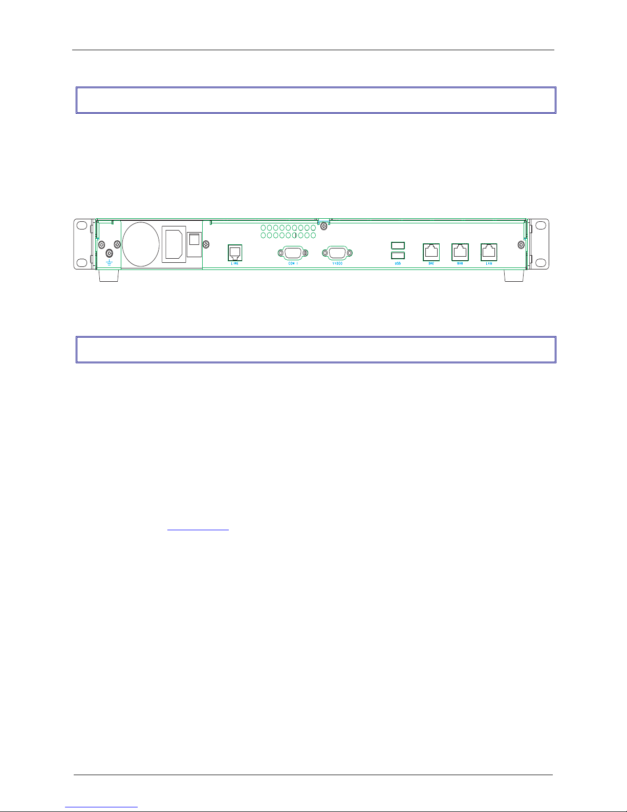
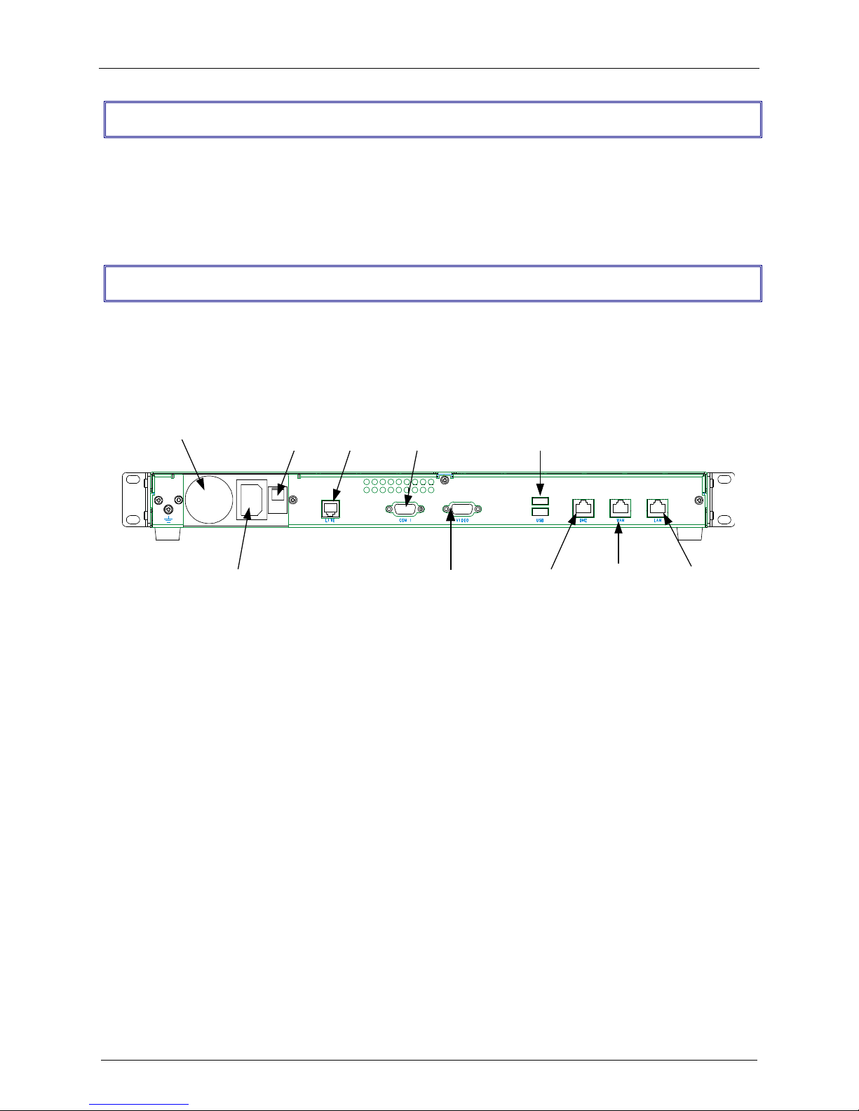
The RF650VPN back panel has a fan, a power plug, the POWER Switch (| / o), an RJ-11 LINE jack, a
DB-9 COM1 jack, a DB-15 High-density DSUB (VIDEO) jack, two USB (Revision 1.1 compliant) jacks, an
RJ-45 DMZ jack, an RJ-45 (WAN) jack, and an RJ-45 (LAN) jack.
The RF650VPN back panel is illustrated and described below.
The RF650VPN Back panel
The back panel components are described in detail in the Cabling Procedure section in Chapter 2 of this
manual.
Ship Kit Contents
The RF650VPN is shipped with the following:
· one RF650VPN
· one or two power cords (two for Euro/UK model)
· one printed Quick Start Guide
· one 44-pin (m) to 40-pin (f) HDD-to-CDR adapter
· two Rack Mounting Brackets and four mounting screws
· one RF650VPN System CD with License Key
If any of these items are missing, contact Multi-Tech Systems or your dealer or distributor. Inspect the
contents for signs of any shipping damage. If damage is observed, do not power up the RF650VPN;
contact Multi-Tech’s Tech Support for advice.
Multi-Tech RouteFinder RF650VPN User Guide 7
Page 8

Chapter 1 – Introduction and Description
Features
· Supports up to 256 IPSec and/or 128 PPTP VPN tunnels for secure LAN-to-LAN and Client-to-LAN
access over the Internet (Note: IPX and Netbeui not supported when using PPTP tunneling.)
· Utilizes 168-bit Triple Data Encryption Standard (3DES)
· 3DES encryption throughput of 15M bps
· Built-in Stateful Packet Inspection firewall with Network Address Translation (NAT)
· Automatic system updates to protect your network against the latest threats
· Application layer security using SMTP, HTTP, DNS and SOCKS proxies
· Improves network performance to frequently accessed web sites with built-in caching server
· Secure local or remote management using HTTPS or SSH
· Reporting function provides valuable troubleshooting information
· Three built-in 10/100 Ethernet ports (LAN, WAN, DMZ)
· Shared broadband or dedicated Internet access for up to 255+ LAN users with one IP address
· Internet access control tools provide client and site filtering
· Traffic monitoring and reporting
· IP address mapping/port forwarding and DMZ port
Specifications
LAN Ports: Number of Ports: 3 (LAN, WAN and DMZ port)
Interface: 10BaseT/100BaseT
Standards: 802.3
Encryption: Algorithms: 168-bit Triple Data Encryption Standard (3DES-CBC), MPPE 40-bit/128-bit
Throughput: 15M bps (3DES)
Protocols: Security: IPSec, IKE, NAT, PPTP, HTTPS, SSH, SCP
Authentication: Shared secret and built-in authentication server
Network: TCP/IP, DNS
Filtering: Protocol, port number, and IP address
Proxies: HTTP, SMTP, DNS, SOCKS
Processor: Pentium-class 566MHz processor (field upgradeable)
Memory: 128MB (field upgradeable)
Disk Space: 10 GB hard drive (field upgradeable)
Power: Voltage & Frequency: 100-240v AC, 50-60 Hz
Power Consumption: 30 Watts
Physical Description: 17" w × 1.75" h × 10.5" d; 10 lbs. (1U rackmountable)
(43.18 cm × 4.45 cm × 26.67 cm; 4.54 kg)
Operating Environment: Temperature Range: 32º – 120º F (0-50º C)
Humidity: 25-85% noncondensing
Approvals: FCC Part 68, FCC Part 15 (Class A), CE Mark, UL60950
Multi-Tech RouteFinder RF650VPN User Guide 8
Page 9

Chapter 1 – Introduction and Description
Pre-Installation Planning - the Organizational
Security Policy
Having an organization-wide security policy is the first and perhaps most important step in general
security planning. Organizations without a well-devised top level security policy will not have ready
answers to questions such as:
· Who is allowed access to which servers ?
· Where are the backups stored ?
· What is the recovery procedure for a security breach ?
These questions must be answered in terms of security costs, useability, compatibility with internal
"culture", and alignment with your site's legal requirements.
Putting a security policy in place and keeping abreast of new security issues as they arise are paramount
to securing your network.
Security management is one of the categories defined by the ISO (International Standards
Organization) from http://www.iso.ch/welcome.html and http://www.iso.ch/iso/en/ISOOnline.frontpage .
Sources of security policy information include the SANS Institute, Microsoft, FreeSwan and other
sources.
The SANS (System Administration, Networking, and Security) Institute, founded in 1989, is a
cooperative research and education organization of more than 96,000 system administrators, security
professionals, and network administrators. The SANS community creates System and security alerts and
news updates, Special research projects and publications, In-depth education, and Certification. Contact
the SANS at http://www.sans.org/newlook/home.htm .
Linux FreeS/WAN is an implementation of IPSEC and IKE for Linux. Several companies are co-operating
in the S/WAN (Secure Wide Area Network) project to ensure that products will interoperate. There is
also a VPN Consortium fostering cooperation among companies in this area. FreeS/WAN source code is
freely-available, runs on a range of machines including cheap PCs, and is not subject to US or other
nations' export restrictions: http://www.freeswan.org/.
Microsoft Windows 2000 and Windows NT security and related HowTos, Problem Solving,
Documentation, Security Bulletins, and Troubleshooting are available at:
http://www.microsoft.com/technet/default.asp.
Attrition.org (http://www.attrition.org) is a computer security Web site dedicated to the collection,
dissemination and distribution of information about the industry for anyone interested in the subject. They
maintain one of the largest catalogs of security advisories, cryptography, text files, and denial of service
attack information. They are also known for the largest mirror of Web site defacements and their crusade
to expose industry frauds and inform the public about incorrect information in computer security articles.
ATTRITION.ORG is a privately owned and operated system hosted via Inficad Computing and Design.
Computer Security Index FAQ Home Page: http://web.superb.net/islander/crypto/alt-security-keydist-
FAQ.html
The CERT (Computer Emergency Reponse Team) site at ftp://info.cert.org/ lists all of the Coordination
Center (CERT-CC) past advisories, as well as 24-hour technical assistance in responding to computer
security incidents.
Multi-Tech RouteFinder RF650VPN User Guide 9
Page 10

Chapter 1 – Introduction and Description
RISKS (Risks to the Public in the Use of Computers and Related Systems) is a moderated forum for
the discussion of risks to society from computers and computerization. Their web site is at
http://catless.ncl.ac.uk/Risks.
The NIAP (National Information Assurance Partnership) was created in 1997 to join the efforts of the
National Institute of Standards and Technology (NIST) and the National Security Agency (NSA) to meet
the security testing, evaluation, and assessment needs of both IT producers and consumers. Its long-term
goal is to boost consumer confidence in their information systems and networks. Agencies such as the
Federal Aviation Administration are starting to work with NIAP to better define their security requirements,
and NIAP is looking for other target communities where the organization can serve as a catalyst to spur
security requirements and standardization of rules.
See http://niap.nist.gov/niap/objectives.html
GASSP (Generally Accepted System Security Principles) began in mid-1992 in response to a 1990
recommendation from the National Research Council. The effort is sponsored by the International
Information Systems Security Certification Consortium (ISC2), an international common-criteria effort to
develop IT product-related information security principles.
Its objectives include promoting good practices and providing an authoritative point of reference for IT
professionals and a legal reference for the rest of the world for information security principles, practices,
and opinions. The GASSP Pervasive Principles have been developed, and work has begun on defining
and mapping the GASSP Broad Functional Principles.
Go to http://web.mit.edu/security/www/gassp1.html
The Center for Internet Security - The Center, founded in October 2000, is focused on helping
organizations worldwide manage information security risk efficiently. The group, which is vendor- neutral,
provides tools to measure, monitor, improve, and compare the security status of Internet-connected
systems and appliances. Some 200 members help identify the top security threats and participate in
creating practical methods to reduce those threats. The Center's web site is at http://www.cisecurity.org/.
The British Standard (BS) 7799 is an enterprise security policy standard popular in several European
countries. The BS 7799 standard has two main elements: a code of practice for information security
management and a specification for information security management systems. It prescribes a specific
process to determine what policies should be in place, how to document them, and how to develop those
that are not specifically identified in the model.
CASPR (Commonly Accepted Security Practices & Recommendations)
launched in August 2001,
CASPR focuses on distilling expert information via free papers available via the Internet. With the Open
Source movement as a guide, CASPR has approximately 100 certified security professionals involved
and is actively recruiting subject matter experts in all areas of information security.
http://www.caspr.org/aboutcaspr.php
IETF (Internet Engineering Task Force) the international standards body that has standardized the IP
protocol and most of the other successful protocols used on the Internet. The IETF web page is at
http://www.ietf.org/. To help get started with a security policy, try RFC2504 - Users' Security Handbook,
and RFC 2196 - Site Security Handbook.
Multi-Tech RouteFinder RF650VPN User Guide 10
Page 11

Chapter 1 – Introduction and Description
All enterprises should have a carefully planned security policy that protects their network. Your security
policy should define both what should be protected as well as how it should be protected. A
comprehensive, clear and well-communicated security policy is an important first step in protecting any
network from the many threats associated with the power of the Internet.
A corporate Internet security policy should cover at least 6 major areas, including:
1.
Acceptable Use – here you must define the appropriate use of the network and other computing
resources by any and all users. This should include policy statements like: “password sharing is not
permitted"; "users may not share accounts"; and "users may not make copies of copyrighted
software.”
Remote Access – outlines acceptable (and unacceptable) means of remotely connecting to the
2.
internal network. Cover all of the possible ways that users remotely access the internal network, such
as dial-in, ISDN, DSL, cable modem, Telnet and others. Specify who is allowed to have remote
access as well as how users may obtain remote access. The security policy must also address who
is allowed high-speed remote access and any extra requirements associated with that privilege (e.g.,
all remote access via DSL requires that a firewall be installed). You will also want to define users' Email security here (e.g., in MS Outlook at Tools|Options|Security|Zone Settings|Security
Settings).
3.
Information Protection – provide guidelines to users that define the use of and transmission of
sensitive information to ensure the protection of your enterprise’s key elements of information (e.g.,
set a standard for encryption level (such as 3DES) for information sent over the Internet.
Firewall Management – define how firewall hardware and software is managed. This includes change
4.
requests and approval, periodic review of firewall configurations, and firewall access privilege setting.
5.
Special Access – provide guidelines for any special, non-standard needs for access to specialized
networks or systems.
6.
Network Connection – establish policies for adding new devices and new users to the network, with
an approval process, along with the associated security requirements.
The policy statements should be clear, easy to understand and supported by management.
Note: This document contains links to sites on the Internet which are owned and operated by third
parties. Multi-Tech Systems, Inc. is not responsible for the content of any such third-party site.
Multi-Tech RouteFinder RF650VPN User Guide 11
Page 12
Chapter 1 – Introduction and Description
RF650VPN Technology
Before we look at how the RouteFinder works and how to use it, we will illustrate why the RouteFinder is
necessary for the protection of networks, as well as show which problems and risks exist without an
appropriate security system.
Networks
These days, the Internet is firmly established as the key technology for communication and information
procurement; as a storage medium for knowledge and experience values and as the market place for
information services. Since the beginning, its dimensions have multiplied and from 1995 to 2001, the
world wide increase in domains names has been almost exponential.
The systems in the global network communicate via the Internet Protocol Family (IP), including TCP, UDP
or ICMP. The IP addresses are the basis of this communication. They clearly identify all available units
within the network.
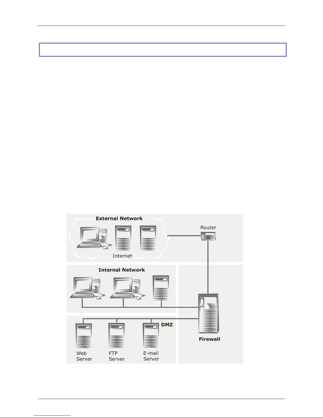
The Internet itself is actually just a collection of computer networks around the world of varying shape,
size and speed. Where two or more networks join, a whole host of tasks arise, which are dealt with by
routers, bridges or gateways. A special type of connection between two networks is called a firewall.
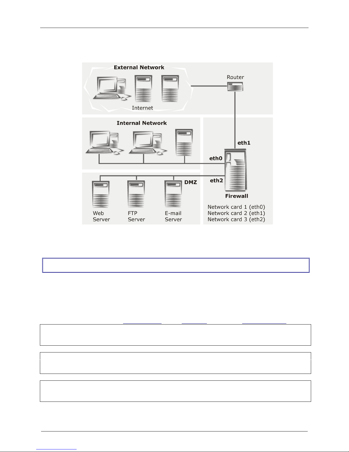
Generally speaking, three types of networks meet at the firewall:
1. External network/Wide Area Network (WAN)
2. Internal Network/Local Area Network (LAN)
3. De-Militarized Zone (DMZ)
Firewall Network Connections
Multi-Tech RouteFinder RF650VPN User Guide 12
Page 13

Chapter 1 – Introduction and Description
The Firewall
The characteristic tasks of a firewall as a connection between WAN, LAN and DMZ are:
· Protection from unauthorized access
· Access control
· Ensure information integrity
· Perform analysis of protocols
· Alert the administrator of relevant network events
· Conceal internal network structure
· Decoupling of servers and clients via proxies
· Ensure confidentiality
There are several generic network components that, brought together under the heading Firewall, are
responsible for these tasks. The following sections provide a brief look at some of the forms and their
derivatives.
Network Layer Firewalls: Packet filter
As the name suggests, this is where IP packets (consisting of address information, some flags and the
payload) are filtered. With this kind of firewall you can grant or deny access to services, according to
different variables. Some of these variables are:
· The source address
· The target address
· The protocol (e.g. TCP, UDP, ICMP)
· The port number
The great advantage of a network layer firewall is its independence of both the operating system and the
applications running on the machine.
In more complex network layer firewall implementations, the packet filtering process includes the
interpretation of the packet payload. The status of every current connection is analyzed and recorded.
This process is called stateful inspection.
The packet filter records the state of every connection and only lets packets pass that meet the current
connection criteria. This is especially useful for establishing connections from a protected network to an
unprotected network.
If a system establishes a connection to a protected network, the Stateful Inspection Packet Filter lets a
host’s answer packet pass back into the protected network. If the original connection is closed, no system
from the unprotected network can send packets into the protected network any longer – unless you
explicitly allow it.
Well Known Ports are controlled and assigned by the IANA, and on most systems can only be used by
system (or root) processes or by programs run by privileged users. Ports are used in TCP (RFC793) to
name the ends of logical connections which carry long term conversations, and typically, these same port
assignments are used with UDP (RFC768). The assigned ports are in the range 0-1023. IETF RFC 1700
provides a list of the well-known port number assignments.
IETF RFCs are available on the Internet from a number of sources.
Multi-Tech RouteFinder RF650VPN User Guide 13
Page 14
Chapter 1 – Introduction and Description
Application Layer Gateways: Proxies
A second significant type of firewall is the application layer gateway. It is responsible for buffering
connections between exterior systems and your own system. Here, the packets aren’t directly passed on,
but a sort of translation takes place, with the gateway acting as an intermediary stop and translator.
The application gateway buffering processes are called proxy servers, or, for short‚ proxies. Every proxy
can offer further security features for the task it is designed for. Proxies generally offer a wide range of
security and protocol options.
Each proxy serves only one or a few application protocols, allowing high-level security and extensive
logging and analysis of the protocol’s usage.
Examples of existing proxies are:
· The SMTP proxy, responsible for email distribution and virus-checking.
· The HTTP proxy, supporting Java, JavaScript, ActiveX-Filter, and ad banner filtering.
· The SOCKS proxy (the generic circuit-level proxy) which supports applications such as FTP
clients, ICQ, IRC, or streaming media.
Application level gateways offer the advantage of physical and logical separation of the protected and
unprotected networks. They make sure that no packet is allowed to flow directly between networks,
resulting in higher security.
Protection Mechanisms
Further mechanisms ensure added security. Specifically, the use of private IP addresses in combination
with Network Address Translation (NAT) in the form of
· Masquerading
· Source NAT (SNAT)
· Destination NAT (DNAT)
These allow a whole network to hide behind one or a few IP addresses, preventing the identification of
your network topology from the outside.
Firewall Connectivity
Multi-Tech RouteFinder RF650VPN User Guide 14
Page 15
Chapter 1 – Introduction and Description
With these protection mechanisms in place, Internet connectivity remains available, but it is no longer
possible to identify individual machines from the outside.
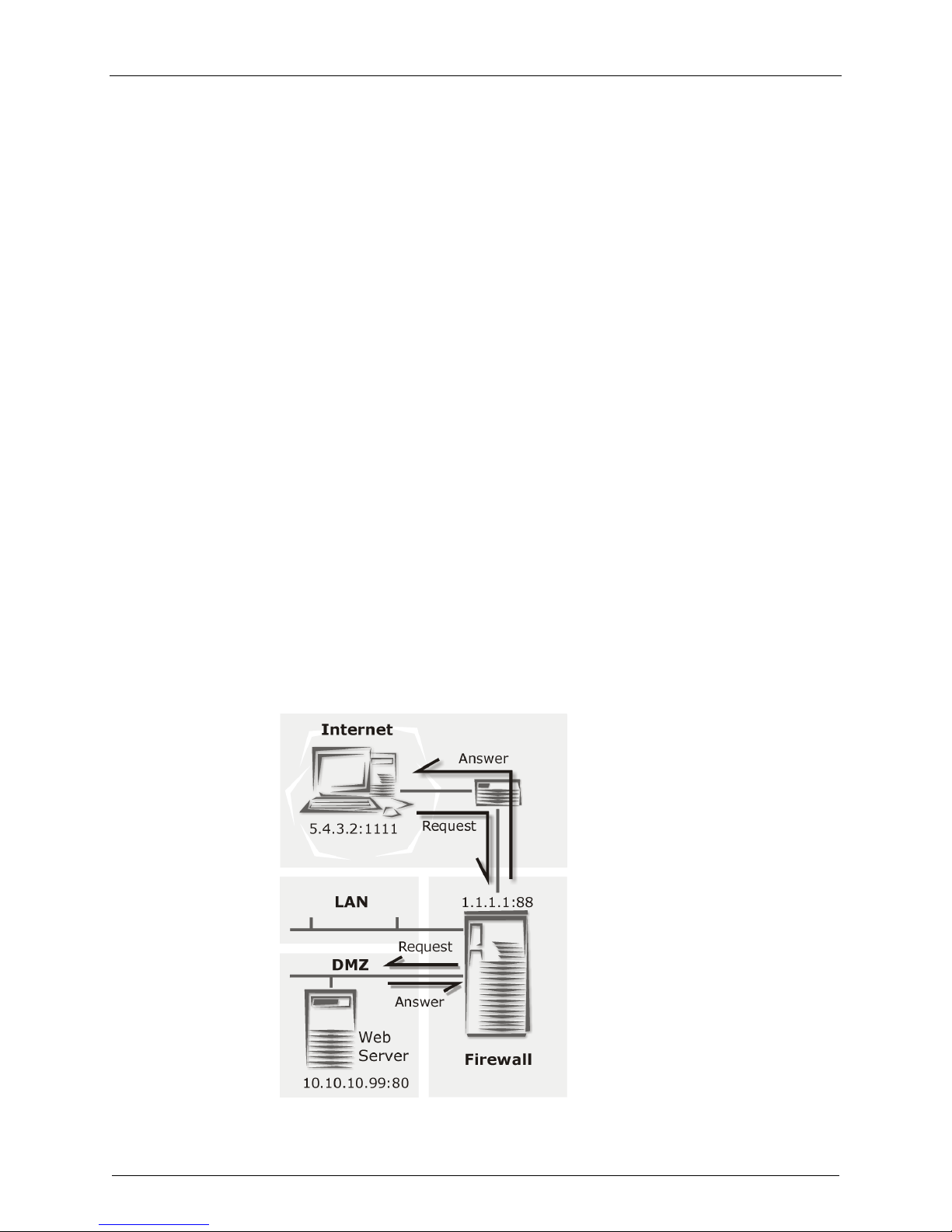
By using Destination NAT (DNAT), it is still possible to place servers within the protected network/DMZ
and make them available for a certain service.
In the sample graphic above, a user with the IP 5.4.3.2, port 1111 sends a request to the web server in
the DMZ. Of course the user only knows the external IP (1.1.1.1, port 80). By using DNAT, the
RouteFinder now changes the external IP address to 10.10.10.99, port 80 and sends the request to the
web server. The Web server then sends off the answer with its IP address (10.10.10.99, port 80) and the
IP of the user. The RouteFinder recognizes the packet by the user address and changes the internal IP
(10.10.10.99, port 80) into the external IP address (1.1.1.1, port 80).
To satisfy today’s business world needs, the IT infrastructure must offer real-time communication and cooperate closely with business partners, consultants and branches. Increasingly, the demand for real-time
capability is leading to the creation of so called extranets, that operate either:
· via dedicated lines, or
· unencrypted via the Internet
Each of these methods has advantages and disadvantages, as there is a conflict between the resulting
costs and the security requirements.
Virtual Private Networking (VPN) establishs secure (i.e., encrypted) connections via the Internet, an
important function especially if your organization operates at several locations that have Internet
connections. Theses secure connections use the IPSec standard, derived from the IP protocol IPv6.
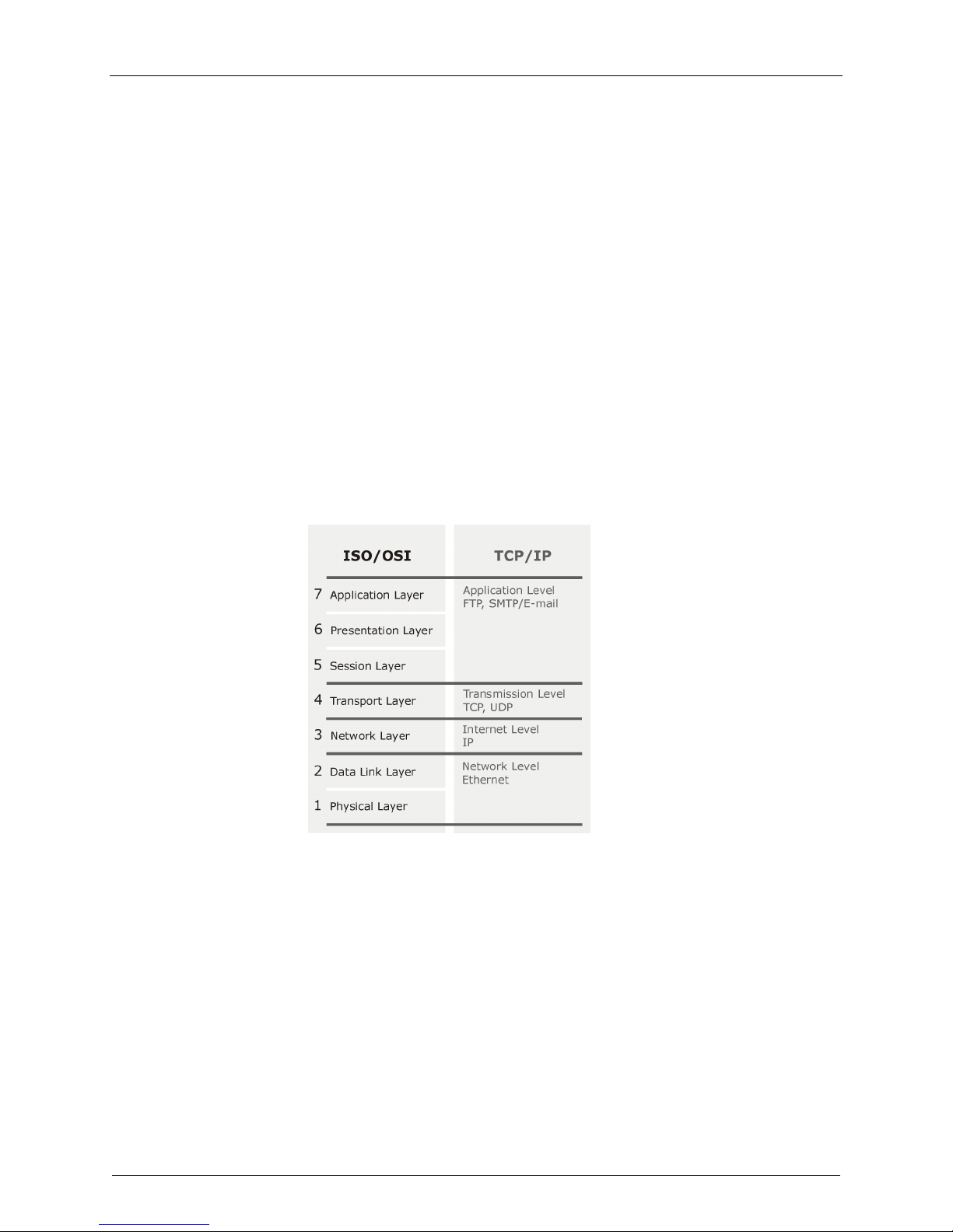
ISO Layers and TCP/IP
Once set up, this encrypted connection is used automatically (i.e., without extra configurations or
passwords at the client systems) regardless of the type of data that is to be transferred, so as to protect
the content during the transport. At the other end of the connection, the transferred data is transparently
decoded and is available for the recipient in its original form.
The RF650VPN uses a hybrid of the above listed basic forms of firewalls and combines the advantages of
both variations: the stateful inspection packet filter functionality offers platform-independent flexibility, and
the ability to define, enable or disable all necessary services.
Existing proxies make the RouteFinder an application gateway that secures vital client system services,
such as HTTP, Mail and DNS by using proxying. It also enables generic circuit-level proxying via SOCKS.
VPN, Source NAT, Destination NAT, masquerading and the ability to define static routes make the
dedicated firewall an efficient distribution and checkpoint in your network.
Multi-Tech RouteFinder RF650VPN User Guide 15
Page 16

Chapter 2 – Installation
Chapter 2 - Installation
Introduction
RF650VPN installation is divided into three parts:
· Hardware installation and cabling
· Software initial configuration
· Software configuration
Additional WebAdmin information is provided in the online Help. The Help function is opened by clicking
the online Help button.
Note: Before installing, you should first plan your network and decide which computer is to have access
to which services. This simplifies the configuration and saves you a lot of time that you would otherwise
need for corrections and adjustments.
Note: Please print this document and use it to fill in your specific RouteFinder and network information
(e.g., the IP address used, e-mail lists, etc.). Enter the configuration information (e.g., the Default
Gateway and other IP addresses used) into the appropriate field of the Address Table later in this
chapter, and keep for future reference.
Administrator requirements to be met before installing the RF650VPN software:
· Correct configuration of the Default Gateway
· An HTTPS capable browser (e.g., Microsoft Internet Explorer 4.0 or higher, or Netscape
Communicator 4.0 or higher)
· JavaScript and Cascading Style Sheets must be activated
· No proxies may be entered in the browser
· If Secure Shell (SSH) is to be used, an SSH client program is required (e.g., PuTTY in Windows
2000, or the bundled SSH client in most Linux packages).
Multi-Tech RouteFinder RF650VPN User Guide 16
Page 17
Chapter 2 – Installation
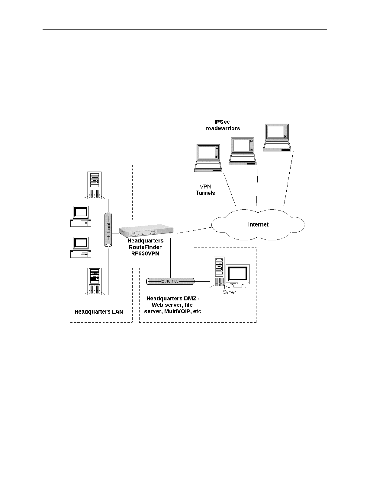
As shown below, the RouteFinder provides the connection between your internal network and the
external network.
RouteFinder Connections
Address Table
Enter the configuration information (e.g., the Default Gateway and other IP addresses used) into the
appropriate field of the Address Table below. Please print this document and use it to fill in your specific
RF650VPN and network information (e.g., the IP address used, e-mail lists, etc.) , and keep for future
reference.
IP Address Net Mask
Network Card connected
to the internal network ___.___.___.___ ___.___.___.___
(LAN on eth0)
Network Card connected
to the external network ___.___.___.___ ___.___.___.___ ___.___.___.___
(WAN on eth1)
Network Card
connected to the DMZ ___.___.___.___ ___.___.___.___
(eth2)
Default Gateway
Multi-Tech RouteFinder RF650VPN User Guide 17
Page 18

Chapter 2 – Installation
Safety Warnings
1. Use this product only with UL- and CUL-listed computers.
2.
To reduce the risk of fire, use only 26 AWG or larger telephone wiring.
Never install telephone wiring during a lightning storm.
3.
Never install a telephone jack in a wet location unless the jack is specifically designed for wet
4.
locations.
5. Never touch uninsulated telephone wires or terminals unless the telephone line has been
disconnected at the network interface.
6.
Use caution when installing or modifying telephone lines.
7.
Avoid using a telephone (other than a cordless type) during an electrical storm; there is a risk of
electrical shock from lightning.
8.
Do not use a telephone in the vicinity of a gas leak.
* Caution: Danger of explosion if battery is incorrectly replaced. A lithium battery on the
RF650VPN pc board provides backup power for the time-keeping capability. The battery has
an estimated life expectancy of ten years. When the battery starts to weaken, the date and
time may be incorrect. If the battery fails, the board must be sent back to Multi-Tech
Systems for battery replacement.
* Caution: The Phone and Ethernet ports are not designed to be connected to a Public
Telecommunication Network.
Safety Recommendations for Rack Installations
Ensure proper installation of the RF650VPN in a closed or multi-unit enclosure by following the
recommended installation as defined by the enclosure manufacturer. Do not place the RF650VPN
directly on top of other equipment or place other equipment directly on top of the RF650VPN.
If installing the RF650VPN in a closed or multi-unit enclosure, ensure adequate airflow within the rack so
that the maximum recommended ambient temperature is not exceeded.
Ensure that the RF650VPN is properly connected to earth ground via a grounded power cord. If a power
strip is used, ensure that the power strip provides adequate grounding of the attached apparatus.
Ensure that the mains supply circuit is capable of handling the load of the RF650VPN. Refer to the power
label on the equipment for load requirements.
Maximum ambient temperature for the RF650VPN is 50 degrees Celsius (120 degrees Farenheit).
This equipment should only be installed by properly qualified service personnel.
Only connect like circuits. In other words, connect SELV (Secondary Extra Low Voltage) circuits to SELV
circuits and TN (Telecommunications Network) circuits to TN circuits.
Multi-Tech RouteFinder RF650VPN User Guide 18
Page 19
Chapter 2 – Installation
Hardware Installation Procedure
The RF650VPN is designed to install either on a desktop or in a standard EIA 19“ rack, and is shipped
with the mounting hardware to install the RF650VPN in the rack. If installing in a rack,
use the provided mounting hardware and follow the rack enclosure manufacturer’s instructions to safely
and securely mount the RF650VPN in the rack enclosure. Proceed to the cabling procedure.
Cabling Procedure
Cabling your RF650VPN involves making the proper POWER, DMZ, WAN and LAN connections
as described and illustrated below.
FAN
Power
Plug
POWER
On/Off
(O/ |)
Switch
LINE
Jack
(Not
Used)
COM 1
DB-9
Jack
(Not
Used)
VIDEO
Jack
(DB-15
DSub)
USB
ports
(2)
(Not
Used)
DMZ
Ethernet
10/100
Mb
DMZ Port
WAN
Ethernet
10/100
Mb
WAN
LAN
Ethernet
10/100
Mb
LAN Port
Port
RF650VPN Back Panel Connections
1. Using an RJ-45 cable, connect the DMZ RJ-45 jack to the DMZ (optional – e.g., a Voice
over IP gateway, like MultiVOIPs or a public server such as e-mail or web).
2. Using an RJ-45 cable, connect the
3. Using an RJ-45 cable, connect the
4. With the RF650VPN Power switch in the off (O) position and using the supplied power
cord, connect the RF650VPN power plug to a live power outlet.
5. Place the RF650VPN Power switch to the on (|) position to turn on the RF650VPN. Wait for the
RF650VPN to beep a few times, indicating that it is ready to be configured with a web browser.
Caution: Never switch off RouteFinder Power until after you have performed the Shut down
process. Refer to System|Shut down in Chapter 3 of this manual). If the RouteFinder is not properly
shut down before switching off Power, the next start may take a little longer, or in the worst case, data
could be lost.
6. Proceed to the Software Configuration Procedure.
WAN RJ-45 jack to the external network.
LAN RJ-45 jack to the internal network.
Multi-Tech RouteFinder RF650VPN User Guide 19
Page 20
Chapter 2 – Installation
Software Configuration
The RouteFinder software is pre-installed on your RF650VPN. Initial configuration is required in order for
you to run the WebAdmin program and begin operation. The browser-based interface eases VPN
configuration and management. The VPN functionality is based on IPSec and PPTP protocols and uses
Triple DES 168-bit encryption to ensure that your information remains private.
Note: Read the legal information and license agreement at the beginning of the installation.
Caution: Use a safe Password! Your first name spelled backwards is not a sufficiently safe password; a
password such as xfT35$4 is better.
Software Configuration Procedure
1. Connect a workstation to the RF650VPN's LAN port via Ethernet.
2. Set the workstation IP address to 192.168.2.x subnet.
3. Connect to the Internet at the RF650VPN WAN port.
4. Make an Internet PUBLIC IP address so it can be assigned to the
5. Turn on power to the RouteFinder. If you hear a continuous beep, cycle RouteFinder power, connect
an external monitor (refer to Chapter 5 of this manual), run BIOS and check for the hard drive. If you
hear 5 beeps, continue with step 6.
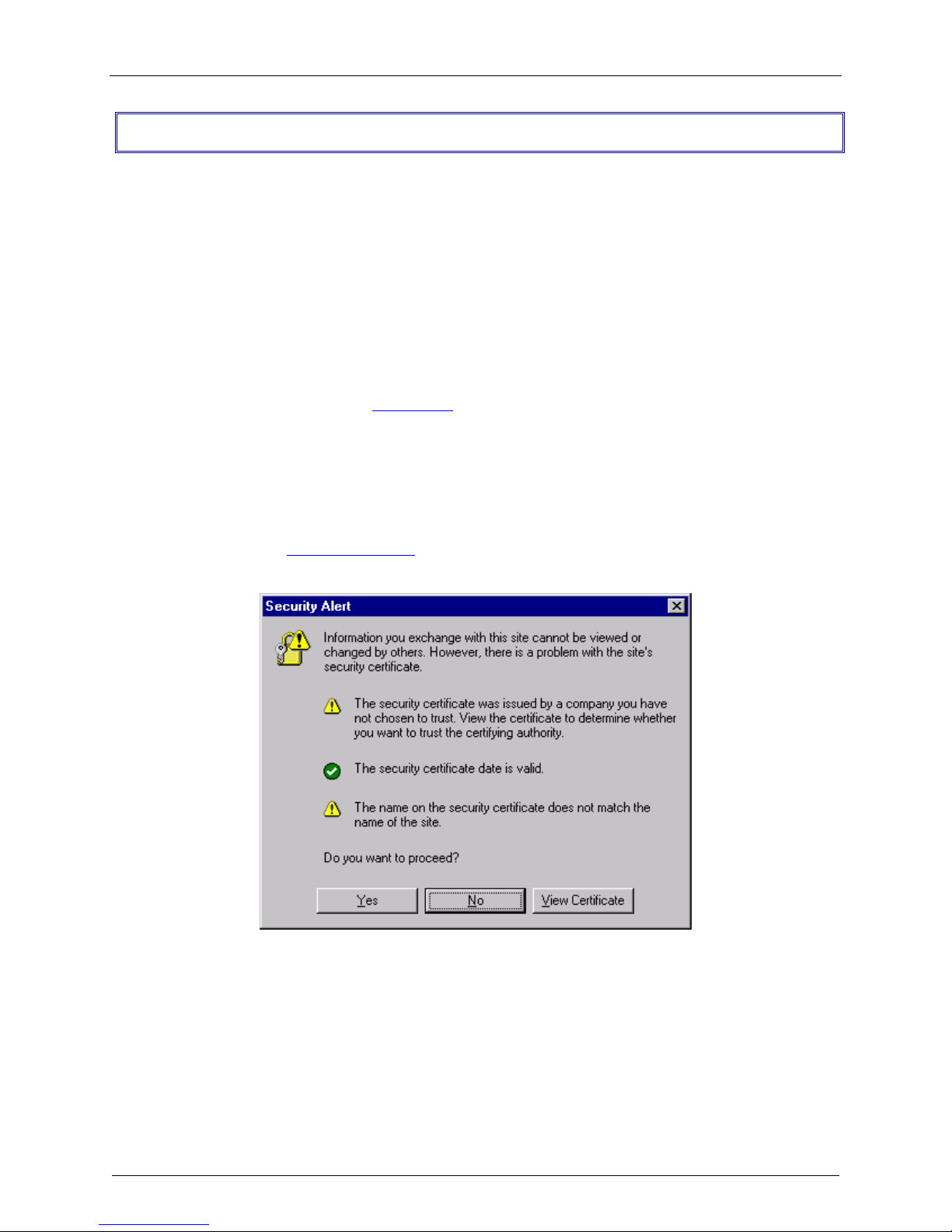
6. Bring up your web browser on the workstation. At the web browser's address line, type the default
Gateway address of https://192.168.2.1 and hit the Enter key. In some environments, one or more
Security Alert screen(s) display.
WAN port.
At the initial Security Alert screen, click Yes and follow any additional on-screen prompts. (This step
is eliminated when you have generated a CA certificate at System|User Authentication|WebAdmin
Site Certificate, described in Chapter 3 of this manual.)
Multi-Tech RouteFinder RF650VPN User Guide 20
Page 21
Chapter 2 – Installation
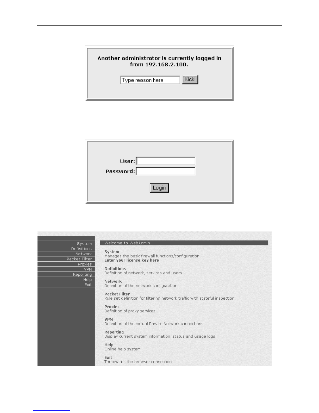
If someone else is already logged in to the RouteFinder, the message below is displayed.
Click the Kick! Button. The Login screen is displayed.
7. Type the default User name as admin (all lower-case), tab to the Password entry and type the
default Password of admin (all lower-case). Click Login. The User and Password entries are case-
sensitive (both must be all lower-case) and can be up to 12 characters each.
Later, you will want to these default User and Password entries to something else.
(If Windows displays the AutoComplete screen, for security reasons, you may want to click No to tell
the Windows OS to not remember the Password.) The Welcome to WebAdmin screen is displayed.
Multi-Tech RouteFinder RF650VPN User Guide 21
Page 22
Chapter 2 – Installation
You Can Now Configure the RouteFinder as Any or All of the
Following:
1. a Firewall
2. a PPTP server for VPN remote client access, and/or
3. an IPSec VPN Gateway
These configuration procedures are provided in the following sections. Note that many of the menus and
entry fields have onscreen status LEDs. A green status light next to a function indicates that the function
is enabled; to disable the function, click the Disable button next to the green status light. A red status
light next to a function indicates that the function is disabled; to enable the function, click the Enable
button next to the red status light.
Note that Appendix A of this manual contains application examples with additional information on
addressing, masking, and software setup.
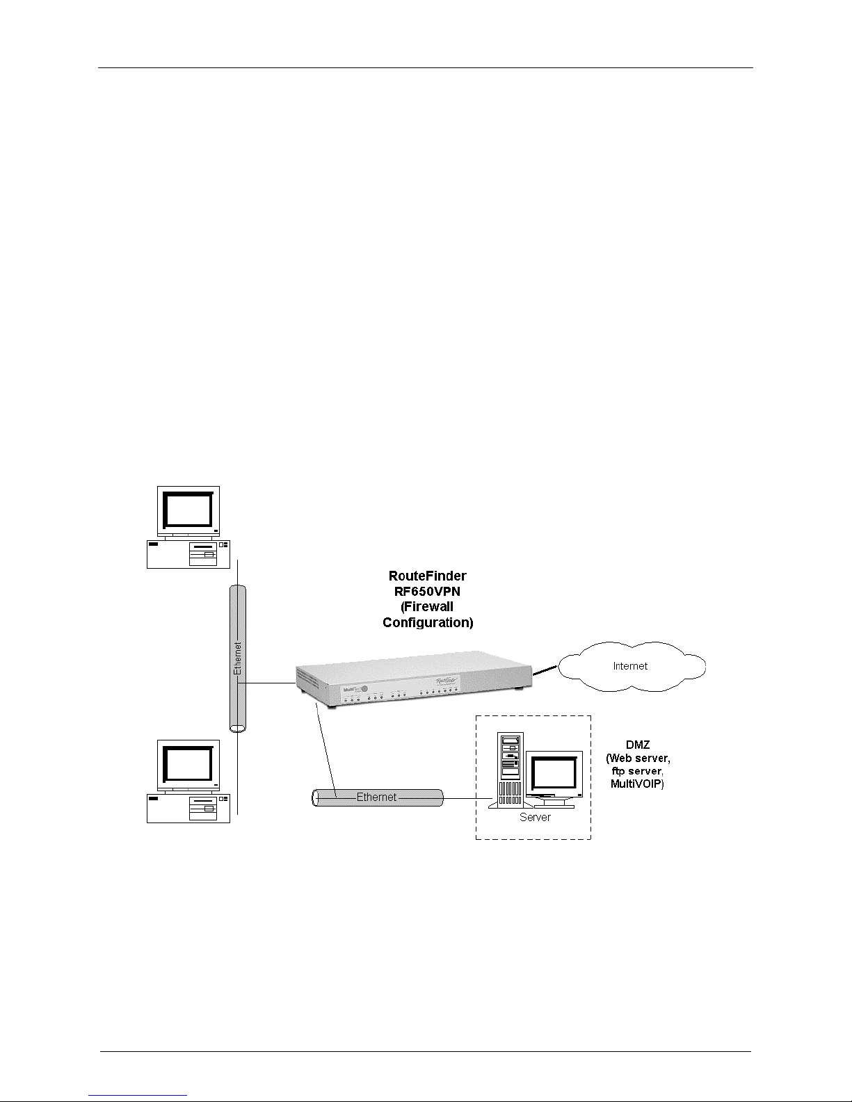
1. Firewall - Configure the RF650VPN as a Firewall
Use this procedure to configure the RF650VPN firewall function as illustrated below.
Multi-Tech RouteFinder RF650VPN User Guide 22
Page 23
Chapter 2 – Installation
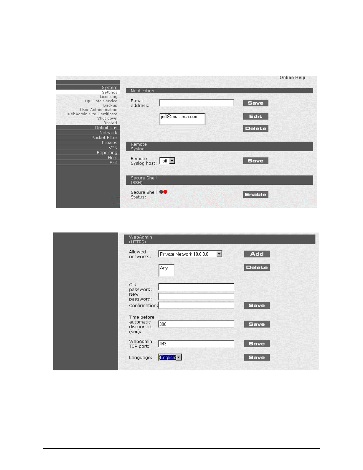
1. At the Welcome to WebAdmin screen, click on System|Settings. The following screen displays.
a) Add your own email address for alerts and notification.
b) Remove the default email address.
c) Optional: you can change the password in WebAdmin as shown below.
Multi-Tech RouteFinder RF650VPN User Guide 23
Page 24
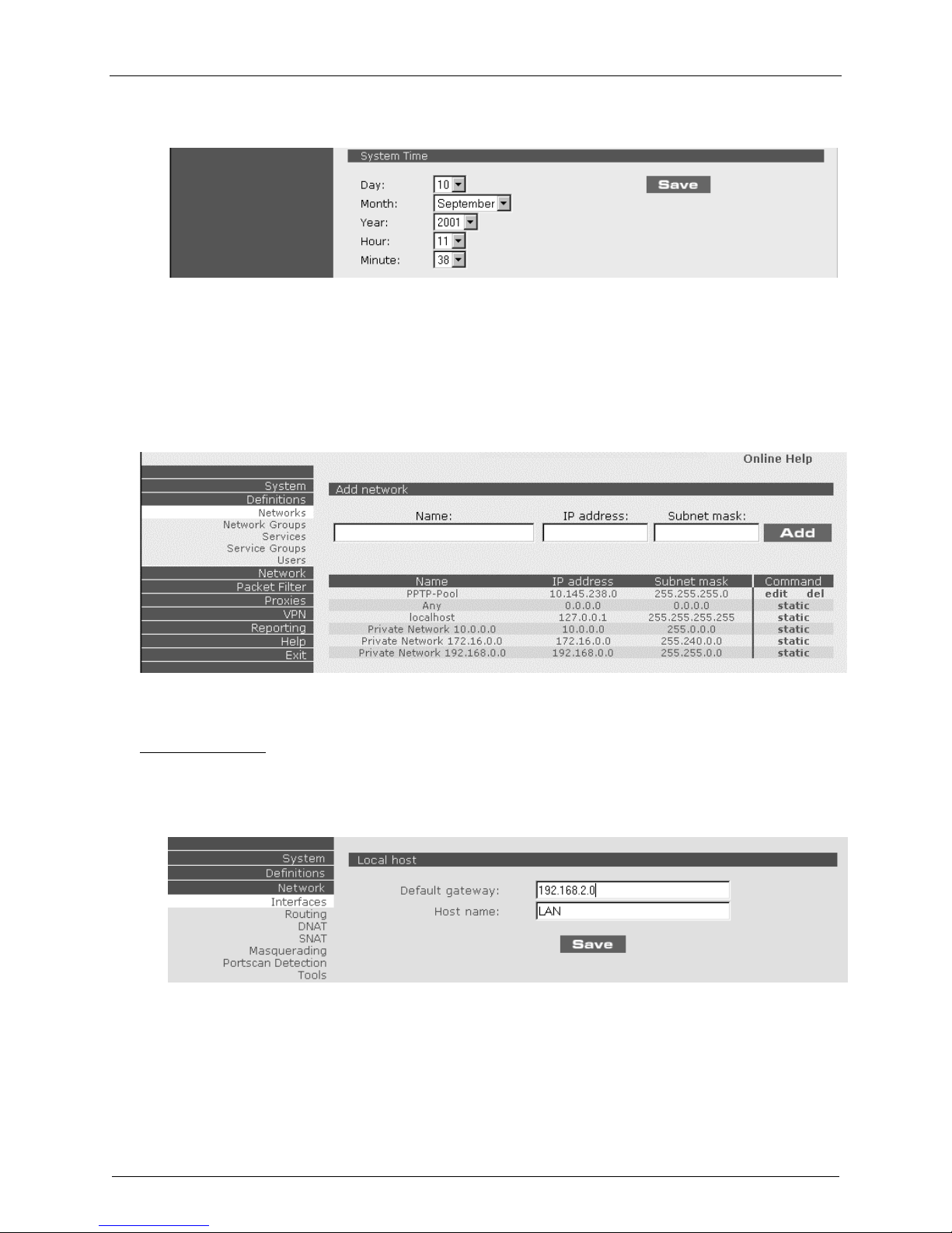
d) Set the System Time and Date to match your current location.
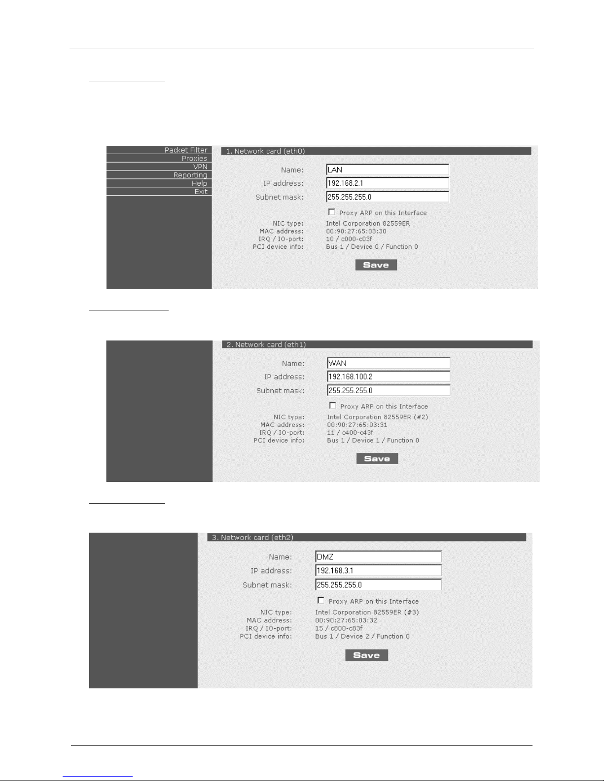
2. Click Definitions|Networks.
Define the IP network that is configured on the LAN port (the Private LAN on eth0).
For example:
Name = LAN
IP address = 192.168.2.0
Subnet mask = 255.255.255.0
Chapter 2 – Installation
3. Click on Network | Interfaces. The Local Host screen displays.
Required changes:
a) Change the Default Gateway IP address; this is the IP address of the router that connects to the
Internet.
b) Change the Host name for the RouteFinder (can be anything).
c) Click Save on the Local host settings screen.
Multi-Tech RouteFinder RF650VPN User Guide 24
Page 25
Chapter 2 – Installation
Optional changes:
d) Change the IP address on LAN port (eth0).
If you change this IP address, you must change the IP address on the workstation so it matches
the new IP address of the RouteFinder in order for you to configure the RouteFinder again.
You also need to reconfigure step 2 so your new IP network is defined.
e) Click Save on the Network card (eth0) settings.
Required changes:
f) Change the IP address on WAN port (eth1); this is the PUBLIC STATIC IP address.
g) Click Save for the Network card (eth1) settings.
Optional changes:
h) Change the IP address on DMZ port (eth2). This is the DMZ zone PUBLIC STATIC IP address.
i) Click Save for the Network card (eth2) settings.
Multi-Tech RouteFinder RF650VPN User Guide 25
Page 26

Chapter 2 – Installation
4. Click on Network|Masquerading.
Select LAN|WAN and click Add; this will enable NAT between the LAN port and the WAN port.
5. Click on Packet Filter|Rules.
a) Add the rule Any – Any – Any – Allow. This allows any service from any server to any client.
Note: you will want to change this rule later.
b) Click on the red circle to enable the rule; the circle will turn green.
6. The RF650VPN is now configured as a Firewall.
Multi-Tech RouteFinder RF650VPN User Guide 26
Page 27
Chapter 2 – Installation
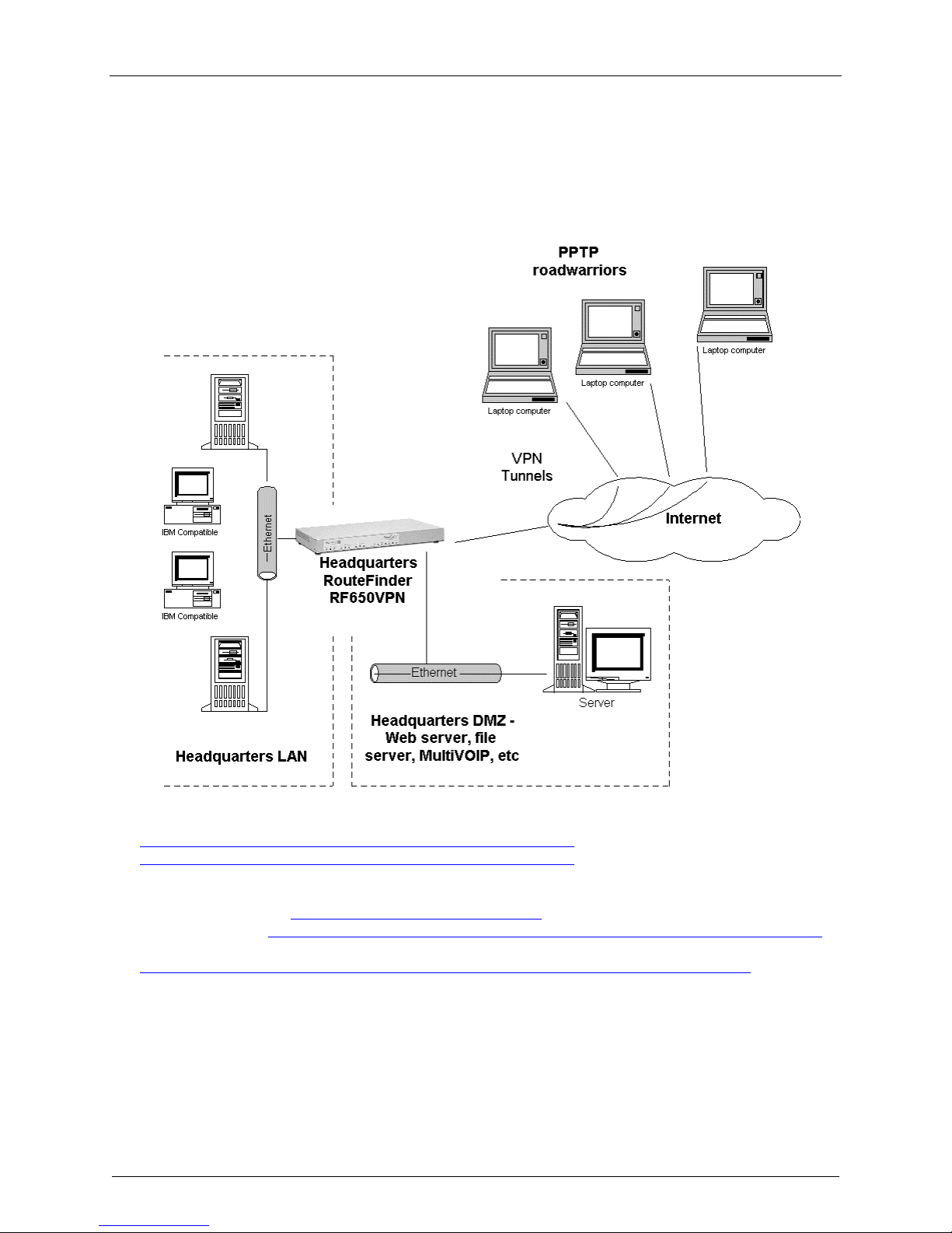
2. PPTP Server for VPN Remote Cient Access
Configure the RF650VPN as a PPTP Server for VPN Remote Cient Access
Use this procedure to configure the RF650VPN as a PPTP server for VPN Remote Client Access (aka,
PPTP Roadwarrior configuration). (Note: IPX and Netbeui not supported when using PPTP tunneling.)
1. Check the following on the Microsoft web site for PPTP updates and patches:
http://support.microsoft.com/support/kb/articles/Q285/1/89.ASP and
http://support.microsoft.com/support/kb/articles/Q191/5/40.ASP
2. Check the following on Microsoft web site for PPTP 128-bit encryption updates:
For Windows 98/Me: http://windowsupdate.microsoft.com/ .
For WindowsNT: http://www.microsoft.com/ntserver/nts/downloads/recommended/SP6/allSP6.asp .
For Windows 2000:
http://www.microsoft.com/windows2000/downloads/recommended/encryption/default.asp
Multi-Tech RouteFinder RF650VPN User Guide 27
Page 28
Chapter 2 – Installation
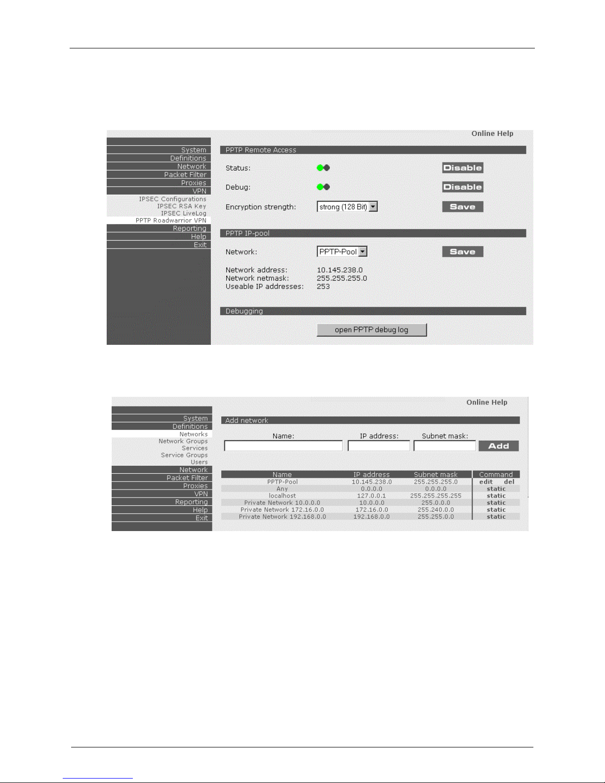
3. Click on VPN|PPTP Roadwarrior VPN. The PPTP Remote Access screen displays.
a) Enable PPTP Status.
b) Enable Debug.
c) Select an Encryption Strength and click Save.
d) Click on Definitions|Networks.
e) In the Command column on the PPTP-Pool line click on Edit to edit the PPTP-Pool settings.
Multi-Tech RouteFinder RF650VPN User Guide 28
Page 29
Chapter 2 – Installation
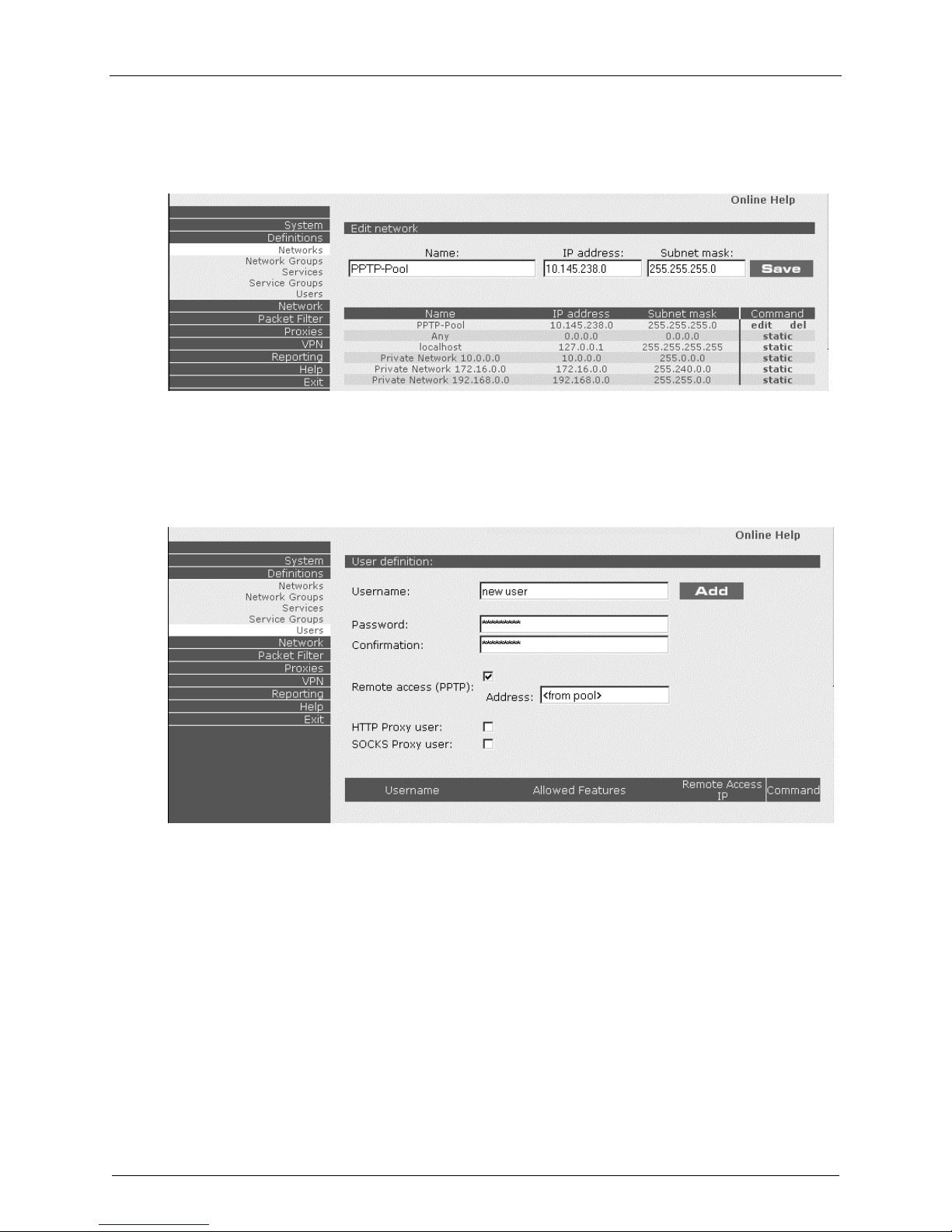
f. The Edit network screen displays. Change the IP address and subnet mask so it is a subnet that
is part of the main IP network of the LAN port (private LAN). (You can assign up to 128
addresses.)
g. Click on Definitions|Users.
h. The User definition screen displays. Define a new user, check Remote access (PPTP), and click
Add.
i. You might have to change the
Any – Any – Any – Allow.
Packet filter rules if you do not already have it set to
Note: you will want to change this rule later.
Multi-Tech RouteFinder RF650VPN User Guide 29
Page 30
Chapter 2 – Installation
3. IPSec VPN Gateway
Configure the RF650VPN as an IPSec VPN Gateway
The RF650VPN configured as an IPSec VPN Gateway supports both LAN-to-LAN and Client-to-LAN
connections. A Client-to-LAN configuration is shown below; a LAN-to-LAN configuration is shown at the
end of this section. The IPSec VPN Gateway Client-to-LAN configuration (aka, IPSec roadwarrior
configuration) is shown below.
The RF650VPN supports the following IPSec parameters and CAN NOT be changed:
- IKE negotiation using main mode
- Encryption using 3DES
- HASH using MD5
- Diffie-Helman using Group 2 (1024) or Group 5 (1536)
- Perfect Forwarding Secrecy (PFS)
Multi-Tech RouteFinder RF650VPN User Guide 30
IPSec Client-to-LAN configuration
Page 31

Chapter 2 – Installation
1. Click on Definitions|Networks. The Add network screen displays.
Define all the Networks and Hosts for the VPN connection.
2. Click on VPN|IPSEC Configurations. The Edit rule screen displays.
a. Enable VPN Status.
b. Enable IKE-Debugging.
c. At New connection: enter a new IPSec connection Name and click Add. (If a Security Alert
screen displays, click Yes.)
Multi-Tech RouteFinder RF650VPN User Guide 31
Page 32

Chapter 2 – Installation
3. The New connection menu displays.
a. Select Yes for Perfect Secret Fowarding.
b. Select IKE for Secure Association.
c. Select Secret as the Authentication method.
d. Enter a shared Secret using alphanumeric characters, the dash (-) or the space or underline (_)
characters.
e. Select the Local Interface and Local subnet. Local Interface should be the Public IP address
of the WAN port; Local subnet should be the private IP Network on the LAN port.
f. Select the Remote IP and Remote subnet. The Remote IP should be the Public IP address of
the WAN port on the remote site; The Remote subnet should be the private IP network on the
LAN port of the remote site. If the remote site is an IPSec client, then select Any for Remote IP
and leave the Remote subnet blank. Click Save.
4. The newly-created IPSec Configuration is displayed.
You may have to change the Packet filter rule if you do not have it set to Any – Any – Any – Allow.
5. The RF650VPN is now configured as a PPTP server for VPN remote client access.
Multi-Tech RouteFinder RF650VPN User Guide 32
Page 33

Chapter 2 – Installation
IPSec VPN Gateway LAN-to-LAN Configuration
The RF650VPN configured as an IPSec VPN Gateway supports both LAN-to-LAN and Client-to-LAN
connections. An IPSec VPN Gateway Client-to-LAN configuration is described and illustrated in the
previous section. An IPSec VPN Gateway LAN-to-LAN configuration is shown below.
Login Using SSH (Secure Shell) and SCP (Secure copy)
Windows SSH and SCP clients can be downloaded from:
http://www.chiark.greenend.org.uk/~sgtatham/PuTTY/
http://winscp.vse.cz/eng/
http://www.ssh.com/products/ssh/
1. The login name for SSH loginuser (default login name) and default password is admin.
2. The Superuser (root) user default password is
3. To change the default password, login as
as loginuser. Use the
(root).
Note: This document contain links to sites on the Internet which are owned and operated by third parties.
Multi-Tech Systems, Inc. is not responsible for the content of any such third-party site.
Multi-Tech RouteFinder RF650VPN User Guide 33
passwd command to change the password for both loginuser and SuperUser
VPN LAN-to-LAN configuration
admin.
SuperUser, type in su at the command prompt after you login
Page 34

Chapter 3 – RouteFinder Software Operation
Chapter 3 – RouteFinder Software Operation
Introduction
WebAdmin is the Web-based configuration interface that you used during the initial configuration in
Chapter 2 - Installation. This chapter describes in detail how to operate the RouteFinder and configure its
functions. With WebAdmin you can perform all the administration functions for the RouteFinder (i.e., you
should not usually need Secure Shell (ssh) access).
The aim of the administrator should be to let as little as possible and as much as necessary through the
RouteFinder, for both incoming as well as outgoing connections.
Note: First, plan your network and decide which computer is to have access to which services. This
simplifies the configuration and saves you a lot of time that you would otherwise need for corrections and
adjustments.
The WebAdmin directory has nine menus (System, Definitions, Network, Packet filter, Proxies, VPN,
Reporting, Help, and Exit) that are described and illustrated in this chapter.
Appendix C of this manual provides an overview of the WebAdmin menu system for your reference.
Multi-Tech RouteFinder RF650VPN User Guide 34
Page 35

Chapter 3 – RouteFinder Software Operation
System
The System menu contains all of the functional configuration sub-menus for the RouteFinder:
Settings
Licensing
Up2Date Service
Backup
User Authentication
WebAdmin Site Certificate
Shut down
Restart
The System menus are described in the following sections.
Multi-Tech RouteFinder RF650VPN User Guide 35
Page 36

Settings
From System|Settings you can define:
Notifications
SSH
WebAdmin (HTTPS)
WebAdmin password
Automatic Disconnect
System Time
Chapter 3 – RouteFinder Software Operation
Multi-Tech RouteFinder RF650VPN User Guide 36
Page 37

Chapter 3 – RouteFinder Software Operation
Notification
Whenever important events occur (e.g., portscans, login with an invalid password, reboots, or notifications
of the self-monitor), the administrator is notified via e-mail. At least one e-mail address must be entered
at System|Settings|Notification.
Note: The Host Name is shown in the reference line in all Notification E-Mails. The Host Name is
configured in the Network|Interfaces menu.
In the Notification window, type in the E-mail address that you want and click Save. You can then Edit
or Delete the entry.
Remote Syslog
In the Remote Syslog window, select the desired Remote Syslog host from the drop-down box and
click Save.
Remote Syslog lets you pass on all log messages of the firewall to another syslog daemon.
This is especially recommended if you want to collect the log files of several systems on one host. The
default setting is ’off’. To activate it, select a host from the Remote Syslog Host select menu that is to
receive the log data and then click the Save button.
The remote host must run a Syslog-compatible daemon to accept the log data. Before you can set the
host here, you must first define it in Definitions|Networks and then select it in System|Settings.
Use a Network netmask of 255.255.255.255 to define a single host.
A remote syslog "how to" is provided in Appendix A of this manual.
Multi-Tech RouteFinder RF650VPN User Guide 37
Page 38

Chapter 3 – RouteFinder Software Operation
Secure Shell (SSH)
The Secure Shell (SSH) is a text-oriented interface to the RouteFinder, suitable only for experienced
administrators. Access via SSH is encrypted and therefore impossible for outside users to tap into. For
access via SSH you need an SSH Client, which most Linux distributions already include (refer to
Appendix G of this manual for information on Linux ssh clients).
For MS Windows, the program PuTTY is recommended as an SSH client.
To log into the RouteFinder with Secure Shell (SSH, Port 22), use the "loginuser" account and the
appropriate password that was set up during installation. Change your passwords regularly!
The SSH status must be active (green onscreen LED lit) before you can access the RouteFinder via SSH.
SSH requires name resolution for the access protocol, otherwise a time-out occurs with the SSH
registration. This time-out takes about one minute. During this time it seems as if the connection is frozen,
or can’t be established. After that the connection returns to normal without any further delay.
The networks that are to be allowed to access the RouteFinder using SSH also must be added into the
Allowed Networks menu. The default setting Any in the Allowed Networks selection menu ensures a
smooth installation. That means everyone is allowed to access the SSH service. Networks can be defined
in the Definitions|Networks menu.
Caution: The default setting (Any) allows everyone to access the SSH service. For security reasons we
recommend that you restrict the access to the SSH service. You should delete access from all other
networks!
When deleting a network, the program checks whether you are still able to access WebAdmin from your
active IP address after the deleting procedure. If this is no longer possible, the process is not carried out.
This check is carried out for the security of the administrator, so that s/he cannot become locked out
accidentally. After completing the adjustments, it is a good idea to disable SSH access again for security
reasons.
Multi-Tech RouteFinder RF650VPN User Guide 38
Page 39

Chapter 3 – RouteFinder Software Operation
WebAdmin (HTTPS)
From the System|Settings|WebAdmin (HTTPS) menu you can regulate access to the WebAdmin
configuration tool. The WebAdmin interface uses the Secure HTTP protocol (S-HTTP, aka HTTPS) for
secure transactions. Secure HTTP provides a variety of security mechanisms to HTTP clients and
servers, providing the security service options appropriate to the wide range of potential end uses
possible for the World Wide Web.
S-HTTP supports end-to-end secure transactions, in contrast with the original HTTP authorization
mechanisms, which require the client to attempt access and be denied before the security mechanism is
employed. With S-HTTP, no sensitive data need ever be sent over the network in the clear. S-HTTP
provides full flexibility of cryptographic algorithms, modes and parameters.
The Allowed Networks dropdown list lets you select the networks from which access to WebAdmin is
allowed. You can Add new selections and Delete existing selections such as PPTP-Pool (default),
Private Network 10.0.0.0, and localhost. The RouteFinder will display an ERROR message telling you if
you try to delete access to a network causing you to lock yourself out.
As with SSH, Any has been entered here for ease of installation. In this case, WebAdmin can be
accessed from everywhere, once a valid password is provided.
Caution: As soon as you can limit the location from which the RouteFinder is to be administered (e.g.,
your IP address in the internal network), replace the entry
Any in the selection menu with a smaller
network.
The safest approach is to have only one administration PC given access to the RouteFinder.
You can do this by defining a network with the address of a single computer in the Definitions|Networks
menu.
Multi-Tech RouteFinder RF650VPN User Guide 39
Page 40

Chapter 3 – RouteFinder Software Operation
Change WebAdmin Password
You should change the WebAdmin password immediately after initial installation and configuration, and
also change it regularly thereafter. Select the Allowed networks from the drop-down box. To change the
password for WebAdmin, enter the existing password in the Old Password field, enter the new
password into the New Password field and confirm your new password by re-entering it into the
Confirmation entry field.
Caution: Use secure passwords! For example, your name spelled backwards is not secure enough;
something like xfT35$4 is better.
Time before automatic disconnect (sec)
An automatic inactivity disconnection interval is implemented for security purposes. In the
Time before automatic disconnect entry field, enter the desired timespan (in seconds) after which you
will be automatically disconnected from WebAdmin if no operations take place.
After the initial installation, the default setting is 300 seconds. The smallest possible setting is 60 seconds.
If you close the browser in the middle of an open WebAdmin session without leaving WebAdmin via Exit,
the last session stays active until the end of the time-out and no new administrator can log in.
If using ssh, you can manually remove the active session if you log into the RouteFinder as loginuser via
SSH. With the command SU, you become a root user and can then interrupt the current WebAdmin
connection with rm -f /tmp/wfelock.
To log into WebAdmin, enter the User name and the Password that were set up during initial
installation. Change your passwords often! The default TCP port for WebAdmin is 443, which is also the
default port for HTTPS sessions. You can change the port setting within WebAdmin with the TCP Port
setting.
WebAdmin TCP Port
Enter the port number for WebAdmin TCP Port usage. The default is Port 443.
Change WebAdmin TCP Port
If you want to use the HTTPS service for other purposes (e.g., a diversion with DNAT), you must enter a
different TCP port for the WebAdmin interface here. Possible values are 1-65535, but remember that
certain ports are reserved for other services. We suggest you use ports 440-450. To contact WebAdmin
after the change, you must append the port to the IP address of the RouteFinder separated by a colon
(e.g., https://192.168.0.1:445). Refer to the Well Known Ports section in Chapter 1 of this manual.
Language: (only English is available at this time.)
Multi-Tech RouteFinder RF650VPN User Guide 40
Page 41

Chapter 3 – RouteFinder Software Operation
System Time
These menu selections let you enter the current RouteFinder date and time. Note that large time jumps
can lead to gaps in the Reporting and Logging.
Note: Don’t change from summer- to wintertime and back. We suggest you enter the Greenwich Mean
Time (GMT), regardless of your global position, especially if you plan to operate Virtual Private Networks
across different time zones.
Changing the system time can lead to the following time-warp effects:
Forward time adjustment (winter to summertime)
· The time-out for the WebAdmin has expired and your session is not valid anymore.
· The log information for the appropriate time periods is missing in the time-based reports. Most
diagrams show this time period as a straight line at the height of the old value.
· All the values for Accounting in this time period are 0.
Backward time adjustment (summer to wintertime)
· The time-based reports already contain log information for the corresponding time period which, as
far as the system is concerned, come from the future: this information is not overwritten, but retained.
· The writing of the log files is continued when the point of time before the setback time is reached.
· Most diagrams show the values of this time period as compressed.
· The already-recorded data (from the future) retain their validity for the Accounting function.
The accounting files are continued when the setback time is reached again.
Therefore, it is recommended that the time should only be set once during initial configuration and later
should only be slightly adjusted. No adjustments from winter- to summertime should be made, especially
if the collected reporting and accounting information is to be further processed.
Multi-Tech RouteFinder RF650VPN User Guide 41
Page 42

Chapter 3 – RouteFinder Software Operation
Licensing
From System|Licensing you can enter and view license key information. The Enter license key entry
field contains all zeros initially.
Enter License Key
Enter the license key into the first field and then press the Enter key to expand the license key into the
rest of the fields.
You can only obtain a license key from Multi-Tech sales support. With a valid license key, you are
entitled to use Multi-Tech’s Up2Date service and support. Each RF650VPN ships with a unique
individual License Key. It is a 35-digit code that is provided on the RouteFinder's System CD.
Enter the license key for your RouteFinder and click Add. When you have entered the License Key
accurately the Enter license key screen is re-displayed.
You can then view License Key information from the RouteFinder's WebAdmin software at
System|Licensing. This screen provides the entered License Key number, whether it is a valid License
Key number, the current number of protected (licensed) IP addresses, the Up2Date Service expiration
date, and the Virus Scanner subscription expiration date.
The license key number is a 35-digit alphanumeric entry; the letters must all be in lower-case.
Multi-Tech RouteFinder RF650VPN User Guide 42
Page 43

Chapter 3 – RouteFinder Software Operation
If you enter your license key number incorrectly, the message Error: License is invalid is displayed.
Check the license key number and re-enter it. One common entry error is mistaking a 0 (zero) for an o
(the letter O). Another error is entering upper-case letters or symbols.
The License Key number is tied to and tracked with your RouteFinder's serial number.
Whenever you require additional licenses, you must first provide Multi-Tech with your current License Key
and serial number information in order for us to update your RouteFinder.
With a valid License Key, you are entitled to use Multi-Tech’s Up2Date service and support.
Multi-Tech RouteFinder RF650VPN User Guide 43
Page 44

Chapter 3 – RouteFinder Software Operation
Up2Date Service
From System|Up2Date Service you can define RouteFinder update parameters. With the Up2Date
service, your RouteFinder can be continually updated with new virus patterns, system patches, and
security features. The Up2Dates are signed and encrypted and are read in via an encrypted connection.
The Up2Date Sevice is provided in two separate functions: System Up2Dates and Pattern Up2dates.
The System Up2Date and Pattern Up2Date functions are described in the following sections.
Multi-Tech RouteFinder RF650VPN User Guide 44
Page 45

Chapter 3 – RouteFinder Software Operation
System Up2Date
System Up2Date can import patches, updates and new features into your RouteFinder. With the System
Up2Date service, you can get System Up2Dates manually anytime you want (System Up2Date can only
be started manually).
System Up2Date Procedure
1. Open the Up2Date Service menu in the System directory.
2. In the
is opened during the Up2Date process, in which the newly installed data and the current version are
shown. The process is finished when the message
System Up2Date window, click the Start button next to Get and install System Up2Dates now. A window
DONE appears in the Up2Date process window.
Pattern Up2Date
Pattern Up2date downloads and install new virus detection patterns for the firewall's virus scanner. Click the
Start button in the bottom table to start the Pattern Up2Date process.
To ensure that patterns stay up to date at all times, this process can also be automated.
Enable the automatic function and select an interval.
With the
Pattern Up2Date service, your RouteFinder can be continually updated with new virus patterns
(with optional email virus scan subscription), system patches and security features that can be
automatically read into your running system. The
Up2Dates are signed and encrypted and are read in via
an encrypted connection. The IP address of the appropriate server is automatically entered into the
Up2Date Server entry field.
You can choose update your RouteFinder manually (
it updated automatically at regular intervals (
Only Multi-Tech can create and sign these
Every hour, Every night, or Every week).
Up2Date packets.
Get and install pattern updates now selection), or to have
Multi-Tech RouteFinder RF650VPN User Guide 45
Page 46

Chapter 3 – RouteFinder Software Operation
Manual Pattern Up2Date
1. Open the Up2Date Service menu in the System directory.
2. In the Pattern Up2Date window, click the Start button at Get and install Up2Dates now.
During the Up2Date procedure, a window is opened, in which the new virus patterns are shown.
If your firewall is already up-to-date, you will be informed of this.
The procedure is finished when the message DONE appears.
Automatic Pattern Up2Date
1. Open the Up2Date Service menu in the System directory.
2. Using the Interval select menu in the System directory, define the time interval after which the
RouteFinder checks for new Up2Dates at the specified Up2Date server. The selectable time intervals
are Every hour, Every night, and Every week.
3. Save the time interval by clicking the Save button.
4. Activate the function by clicking the Enable button at Get Up2Dates automatically.
Up2Date uses port 222 TCP for communication with the Up2Date Server. If you have an upstream
firewall, open port 222 (tcp) for the RouteFinder software in order for the U2Date process to work.
The Pattern Up2Date download process is displayed as it progresses.
Caution: Even though effective protection mechanisms have been developed against problems with the
transmission and/or installation of Up2Dates, performing the Up2Date process remains a potential risk
for your system (as with any manual or automatic download).
Multi-Tech RouteFinder RF650VPN User Guide 46
Page 47

Chapter 3 – RouteFinder Software Operation
Backup
The System|Backup function lets you save the settings of your RouteFinder on a local hard disk. With
the backup file, you can set a recently installed RouteFinder to the identical configuration level as an
existing RouteFinder. This is useful in case of a hardware defect – a new RouteFinder can be installed
and the backup read in minutes. This means a replacement system can be running in a very short time.
The backup file contains all configuration settings except the VPN RSA Key.
Note: After every change of RouteFinder settings, create a new backup file and keep this in a safe place.
This ensures that your current RouteFinder settings are always available.
Export Backup (Create Backup Manually)
1. Open the Backup menu in the System directory.
2. Enter a comment into the Export Backup entry field. When you then read in the backup, the comment
is displayed.
3. Click the Start button to create the backup file. The backup file that contains your configuration is now
created on theRouteFinder. The message Backup has been created successfully. Save the
backup file to your local PC. is displayed.
4. Click the Save button to save the backup file on your local PC.
5. Select the option Save file to disk from the file download menu and click OK.
6. Save the file under any name in the Save file under menu.
The file name generated by the RouteFinder is made up of backup’s date and time in the format
backup_yyyymmdd_hhmmss.abf . The file can be saved to your floppy drive, hard drive, CD-ROM drive
or other storage medium. The exported backup file is saved in .ABF format (a format understood only by
the RouteFinder, e.g., backup_20010907_082400.abf in the example above).
Caution: When reading in the Backup file, the RouteFinder automatically configures itself as recorded in
the backup file. For example, if IP addresses or passwords have since changed or have been forgotten,
you might not be able to access the RouteFinder anymore.
Multi-Tech RouteFinder RF650VPN User Guide 47
Page 48

Chapter 3 – RouteFinder Software Operation
Import Backup (Restore)
To import (restore) an existing backup:
1. Open the Backup menu in the System directory.
2. Click the Browse... button next to Import Backup.
3. Select the backup file <File name> that you want to import and click Open.
Note: Do not use a UNC path to read in the backup in Microsoft Windows.
4. Under Import Backup, open the Backup menu and click the Start button. The backup packet is
loaded into the RouteFinder and checked. If the file selected is accepted, the backup information is
provided. If the uploaded file is a valid and version-compatible backup, a brief summary of the backup
content is displayed.
5. Verify the backup information.
6. Import the backup file into the active system by clicking the Start button. The backup is then
imported.
Caution: Backup does not save the system passwords (loginuser, root, lilo) or the RSA key for VPN.
Note for Microsoft Windows users: you must attach network-shares to a logical drive. You can not use
UNC filenames for backup.
You will probably want to keep routine backups of all aspects of your RouteFinder to let you
re-build it in case of an emergency, as well as to use as evidence if and when you discover a successful
attack (letting you compare the before and after states of the RouteFinder).
You may want to store all alerts and notificatons (set up in System|Settings|Notification and described
in Chapter 2 of this manual).
Multi-Tech RouteFinder RF650VPN User Guide 48
Page 49

Chapter 3 – RouteFinder Software Operation
E-Mail Backup File
The E-mail backup file function, when enabled, causes the RouteFinder to automatically email
RouteFinder backup configuration files to you. This ensures backup configuration file availability and lets
you avoid having to manually back up your RouteFinder.
You can define multiple e-mail addresses. By default the first system administrator's e-mail address is
used. When deleting the last email address from the list, this default value is filled in automatically, since
one address must always be present. You can also select a time interval in which to receive the backup
configuration file e-mails (i.e., Daily, Weekly, or Monthly). The file sent to the indicated e-mail address is
typically from 3 - 10 Kb in size.
To delete an unneeded e-mail address, highlight it, click Delete, then click Save.
Generate E-mail Backup File
1. Open the Backup menu in the System directory.
2. In the Interval select menu in the E-mail backup file window, define the Interval after which the
backup file is to be created automatically. The Intervals options are: Daily, Weekly, and Monthly.
3. Save the Interval by clicking the Save button next to the Interval select menu.
4. Enter the e-mail address to which the automatically-created backup file is to be sent at regular
intervals into the E-mail to: entry field.
5. Click the Add button next to the entry field to Add the e-mail address. To add further e-mail
addresses, repeat steps 4 and 5.
6. Enable the E-mail backup file function by clicking the Enable button next to Status:.
The E-mail backup file function is enabled when the green traffic LED is lit.
Multi-Tech RouteFinder RF650VPN User Guide 49
Page 50

Chapter 3 – RouteFinder Software Operation
User Authentication
In System|User authentication you define the external authentication servers to be used with
the SOCKSv5 and HTTP proxy services and which user
These user accounts can be established locally on the RouteFinder in the Definitions|Users menu.
External user databases can also be accessed (e.g., Radius servers or Windows NT or Windows 2000
servers). This can be useful if a user database already exists on such a server, in which case the user
need not be created on the RouteFinder again. User authentication is also used with the PPTP VPN
function. More information about PPTP Roadwarrior VPN is in the VPN directory later in this chapter.
may use these proxy services.
At the IP level, you can also limit the access to the proxy services of your RouteFinder by setting Packet
Filter rules on your internal clients. This poses certain problems, however, if you are using a dynamic
configuration protocol internally, such as DHCP or BOOTP.
In this case, user authentication becomes relevant. When requests are made to a proxy service, the client
must authenticate himself with his user name and password. This makes the authentication person-based
(i.e., user-based) and not IP-based, thus making a person-based Accounting in the HTTP proxy access
protocol possible.
Multi-Tech RouteFinder RF650VPN User Guide 50
Page 51

Chapter 3 – RouteFinder Software Operation
Proxy Services and Authentication Methods
The SOCKSv5 and HTTP proxy services support user authentication. Both proxies can be configured so
that they either accept all clients (based on IP addresses), or only those clients with a valid user name
and password. If you activate
use to evaluate the requested credentials, otherwise the proxy service cannot be used.
The RouteFinder supports user authentication against …
· a Radius server
· a Windows NT SAM user base
· a defined user database in WebAdmin
The three user databases can also be interrogated one after the other.
user authentication, you must determine which method your RouteFinder will
Radius
Radius (Remote Authentication Dial In User Service) is a protocol with which equipment such as an
ISDN router can access information from a central server for user authentication.
Radius also manages technical information needed for the communication of the router with the
equipment of the caller. This includes, for example, the protocols used, IP addresses, telephone numbers,
timeouts, routes, etc. Together they create a user profile that is stored in a file or a database on the
Radius server. Radius can also be used as a generic authentication protocol.
The Radius protocol is very flexible and is available for most operating systems, including Microsoft
Windows NT/2000. The Radius implementation of the RouteFinder lets you configure access rights on the
basis of proxies and users.
Before you can activate the Radius authentication, you need a Radius server on your network. Strictly
speaking, the server could also be somewhere in the external network (Internet).
But, since the passwords are transferred in plain text, we strongly recommend that the Radius server be
located close to the RouteFinder and that they are connected via a switching hub.
In case of transfer via a public network, we recommend the use of an encrypted tunnel.
Multi-Tech RouteFinder RF650VPN User Guide 51
Page 52

Chapter 3 – RouteFinder Software Operation
Microsoft IAS
The following section describes the settings for Microsoft’s IAS (Radius server for MS Windows NT and
2000). If you have a different Radius server, you need the following information to use RouteFinder’s user
authentication.
The Radius receives a request with three data fields:
· User name
· Password in clear text (PAP)
· Type of proxy (string HTTP or SOCKS) in the NAS Identifier field
Based on this information, your RADIUS server should decide whether or not to grant access to the
proxy, and send back an answer packet.
Configuring Microsoft’s IAS Radius Server
IAS is delivered with all versions of Microsoft Windows 2000 Server, but is generally not installed by
default. For Microsoft Windows NT4, IAS is a component of the NT4 Option Pack and is available
without extra charge. The MS Windows NT4 IAS version has fewer features than the 2000 version, but it
is quite sufficient for the usual authentication settings of the RouteFinder.
1. Check whether the IAS service is installed. If it is not, install it.
2. Create a user group for every proxy that is to be used.
Note: Name the group according to the appropriate proxy service. For example, the name for the
HTTP proxy could be called HTTP proxy users. Now assign all those users that are to be able to use
the appropriate service to this group.
3. Activate the user flag Allow dial-in-access to the network of every user in these groups.
This setting is found in the user properties. MS Windows NT/2000 uses this as the “master flag” to
allow any kind of network remote access.
4. Open the administration program for the IAS service.
5. Add a client. This requires the following information:
Any client name: Enter the DNS name of your RouteFinder system here.
Protocol: Choose Radius.
IP address of the client: this is the internal IP address of your RouteFinder system.
Client Vendor: Enter Radius Standard.
A shared secret: enter any password. You will need this password later to configure the Radius
server with the configuration tool WebAdmin.
6. Open the RAS Rules menu. A standard rule is entered here. If you intend to only use IAS for the
RouteFinder, you can delete this entry. Enter a rule for every proxy. Choose the name appropriately
(e.g., HTTP access). Add two conditions:
Condition 1: The NAS-Identifier field must correspond to a string according to the following table:
Proxy-type NAS identifier corresponds to string
HTTP HTTP
SOCKS SOCKS
Condition 2: the Windows group of the accessing user must correspond to the user group
established in step 2. The access is only granted if both conditions are met by the user.
7. Edit the profile of the guideline by allowing unencrypted authentication (PAP). Leave the values of
the other dialog pages unchanged.
Multi-Tech RouteFinder RF650VPN User Guide 52
Page 53

Chapter 3 – RouteFinder Software Operation
8. Open WebAdmin and open the User Authentication menu in the System directory.
At Radius Server IP enter the IP address of the Radius server.
At Radius Server Secret enter the password from step 5.
9. Save the entry by clicking the Save button.
10. Open the menu of the corresponding proxy service in the Proxies register.
11. If User Authentication is still disabled (red light), activate it by clicking the Enable button. At
Authentication types choose Radius from this select menu.
12. Confirm your entries by clicking the Add button.
The Radius user authentication is now active. The IAS server subsequently records every access to the
proxy server in the Microsoft Windows NT/2000 Event Log.
To prevent the event log from overflowing, the RouteFinder stores the information sent by the Radius
server for five minutes. This also means, however, that any changes in the user database might only be
detectable after five minutes.
Multi-Tech RouteFinder RF650VPN User Guide 53
Page 54

Chapter 3 – RouteFinder Software Operation
SAM – NT/2000
This authentication method uses an MS Windows NT/2000 domain controller or a standalone server to
evaluate the requests. Many businesses are already using MS Windows NT/2000 networks that are
based on the MS Windows NT/2000 active directory domain concept.
The advantage of SAM is that it is very easy to configure if there is already a PDC (Primary Domain
Controller), or a simple server with a user database running in the network.
The disadvantage is that this model cannot discern between different user groups and proxies. This
means that you can only grant either all or none of the users access to a particular proxy.
Configure SAM – NT/2000
In order to be able to use this authentication method, your network requires a Microsoft Windows NT or
2000 computer that contains the user information. This can be a Primary Domain Controller (PDC), or an
independent server.
This server has a NETBIOS name (the NT/2000 server name) and an IP address.
1. In WebAdmin, open the User Authentication menu in the System directory.
PDC Name: Enter the NETBIOS name of the primary domain controller into this field. As of Microsoft
Windows 2000, these names are also official DNS names. The RouteFinder only supports names
consisting of alphanumeric and minus and full-stop characters. Special characters such as % ! # _ { }
are not permitted.
PDC IP: Enter the IP address of the primary domain controller into this field.
BDC Name: If you are using a backup domain controller, enter the name into this field. If you do
not have a backup domain controller, enter the PDC’s name again.
BDC IP: Enter the IP address of the backup domain controller into this field. If you do not have a
backup domain controller, enter the PDC’s IP address again.
Domain: Enter the name of your MS Windows NT/2000 domain into this field.
Accepted characters are: the alphabet, the numbers 0 to 9, the minus sign and underscore.
Caution: This is not an Internet domain (e.g., Company.com) but a simple denominator (e.g.,
Intranet). If, instead of using the Microsoft domain concept, you only have a simple server, then
enter the NetBIOS name. This corresponds to the entry in the
2. Confirm your entries by clicking the
Save button.
PDC name entry field.
Note: If you are using SAM authentication, you should deactivate the guest account of your Windows
domain. Otherwise all user/password combinations are counted as valid.
Local Authentication
Before you can use Local authentication, you must activate User Authentication for the respective
proxy services. In Proxies (e.g., Proxies|HTTP or Proxies|SOCKS) check the option Local in the
Authentication types select menu, then click the Add button.
Multi-Tech RouteFinder RF650VPN User Guide 54
Page 55

Chapter 3 – RouteFinder Software Operation
WebAdmin Site Certificate
From System|WebAdmin Site Certificate you can generate a WebAdmin site certificate matching your
enterprise's data, enter the RouteFinder hostname and submit the certificate data. The encryption
processes defined here are an important part of most any modern security system. Cryptographic
processes are employed for the transfer of confidential data via Virtual Private Networks (defined at the
VPN directory), for User Authentication (at System|User Authentication), or, as in this case, for the
secure administration of the RouteFinder via the network. The format of the certificate is defined in the
ITU-T's X.509 standard. Generating a server certificate for your RouteFinder installation allows you to get
rid of the browser warning messages when you access WebAdmin.
It also adds security, and you are warned if the identification of WebAdmin should change. Actually, two
certificates are generated: one CA certificate, to be installed in your browser's certificate store; and one
server certificate, which the RouteFinder will use to authenticate itself to your browser.
Create a Site Certificate for WebAdmin
1. Open the WebAdmin site certificate menu in the System directory.
2. Enter your organization's data into the select menu entry fields:
Country code: Use the default (United States) or change to the country of operation.
State or region: Type the desired state, province, region, etc.. over the default (Defaultstate).
City: Type the city name over the default (Defaultcity).
Company: Type the company name over the default (Defaultcompany).
Org. unit: Type the organizational unit (e.g., Sales & Marketing) over the default (Defaultunit).
Contact e-mail: Type the contact for RouteFinder certificate data (e.g., the RouteFinder
administrator) over the default (myname@mydomain.com).
3At Firewall hostname: enter the RouteFinder's Hostname. Be sure to enter the same Firewall
hostname here that you will use to access the WebAdmin interface in your web browser (this can be
one of the RouteFinder IP adresses as well).
Example: If you access WebAdmin with https://192.168.10.1, the RouteFinder Hostname
setting here must also be 192.168.10.1. If you access WebAdmin with a DNS hostname (e.g.,
https://routefinder.mydomain.com), then use this name instead.
Note: The RouteFinder Hostname field MUST match the hostname or IP address that you use in
your browser to access WebAdmin.
4. When you have entered values for your organization into the entry fields, click Save.
Multi-Tech RouteFinder RF650VPN User Guide 55
Page 56

Chapter 3 – RouteFinder Software Operation
Import the Certificate into your Browser
1. When all of the certificate data is entered and saved, the WebAdmin Site Certificate menu redisplays. at the CA certificate installation pane click Import Certificate into Browser.
2. At the Security Alert window install (import) the CA certificate into your browser by clicking the Yes
button at the bottom of the screen.
3. If your browser asks you what to do with the file, tell it to open it immediately (e.g., Open this file
from its current location on the screen below).
4. Click OK. The Open With screen is displayed if this is a first-time CA certificate import; proceed with
step 5.
If a CA certificate has been imported before, the Certificate Information screen displays; proceed to
step 1 of the following procedure.
Multi-Tech RouteFinder RF650VPN User Guide 56
Page 57

Chapter 3 – RouteFinder Software Operation
5. Select the program to use to open the certificate and click OK. The Save As screen displays.
6. Enter the filename and location to save the certificate file and click Save.
The Download complete screen displays.
7. Check the Close this dialog box when download complete checkbox. Click Open.
The certificates are installed to the Download to: location specified.
Multi-Tech RouteFinder RF650VPN User Guide 57
Page 58

Chapter 3 – RouteFinder Software Operation
Install a Certificate into the Trusted Root Certification Authorities Store
1. At the Certificate Information window click Install Certificate....
2. At the Welcome to Certificate Import Wizard window click Next>.
Multi-Tech RouteFinder RF650VPN User Guide 58
Page 59

Chapter 3 – RouteFinder Software Operation
3. At the Certificate Manager Import Wizard window click Next>. (You can elect to have the certificate
automatically placed or you can Browse... to a particular location. If you elect to place all certificates
into a selected location, follow the on-screen prompts for Select Certificate Store, Physical Stores,
and ... add to Root Stores.)
4. When the certificate has been added to the Root Store, the Completing the Certificate Manager
Import Wizard displays.Click Finish.
Multi-Tech RouteFinder RF650VPN User Guide 59
Page 60

Chapter 3 – RouteFinder Software Operation
5. An Import Successful message displays. Click OK.
This information will be stored for three years.
6. At the Certificate Information window click OK. The certificate is successfully installed.
Note: Due to system time differences and world timezone offsets, it may be that the generated
certificate is reported as NOT YET valid. However, many browsers wrongly report that the certificate
has expired. This is not the case. The generated certificates will become valid after a maximum time
of 12 hours.
Multi-Tech RouteFinder RF650VPN User Guide 60
Page 61

Chapter 3 – RouteFinder Software Operation
Shut Down
The RouteFinder is shut down by clicking the Start button in the Shut down menu. This ends all the
services correctly.
Caution: You can only switch off the RouteFinder's power after you have performed this Shut down
process. If the RouteFinder is not properly shut down before switching off Power, the next start may take
a little longer. In the worst case, data could be lost. Since the RouteFinder is now also checking the
consistency of the file system, it may have to restart up to three times.
The message Do you really want to shut down? is displayed.
· If you do not want to shut down the RouteFinder, click the Cancel button to return to the
System|Shut down menu.
· If you want to shut down the RouteFinder, click the OK button to confirm.
The message System goes down… displays while the shut down process takes place (2 to 5 minutes).
A continuous beep occurs when shutdown is complete; at this point you can power off the RouteFinder.
Caution: You can only switch off the RouteFinder's power after you have performed this Shut down
process. If the RouteFinder is not properly shut down before switching off Power, the next start may take
a little longer. In the worst case, data could be lost. Since the RouteFinder is now also checking the
consistency of the file system, it may have to restart up to three times.
Multi-Tech RouteFinder RF650VPN User Guide 61
Page 62

Chapter 3 – RouteFinder Software Operation
Restart
By clicking the Start button in the Restart menu, the RouteFinder is shut down completely and restarted.
The message Do you really want to shut down? is displayed.
Click the OK button to confirm that you want to restart the RouteFinder WebAdmin software. The
complete restart can take 4 to 5 minutes. When the restart process is complete the RouteFinder will
generate 5 consecutive beeps; you can now continue RouteFinder operation.
If you do not want to re-start the RouteFinder WebAdmin software, click Cancel to return to the
System|Restart menu.
Multi-Tech RouteFinder RF650VPN User Guide 62
Page 63

Chapter 3 – RouteFinder Software Operation
Definitions (Networks and Services)
Network and Host definitions for all further settings (e.g., packet filter, VPN, proxies, networks and
services) are made in the
definitions (names), instead of having to deal with IP addresses, ports and network masks. Being able to
group networks and services is an additional step saver.
All settings that are then made in the network or service groups are valid for all the contained networks.
Groups themselves can also be put together into new groups. Additionally, local users of proxy services
are defined in this directory.
Definitions directory. The advantage of this is that you can then work only with
The definition and configuration of Networks, Network Groups, Services, Service Groups, and Users
are covered in the following sections.
Multi-Tech RouteFinder RF650VPN User Guide 63
Page 64

Chapter 3 – RouteFinder Software Operation
Networks
From Definitions|Networks you can Add, Edit, or Delete a network.
In the Add Network menu, you can add a new network. A network always consists of a Name,
an IP address and a Network Mask.
To define a single host, enter its IP address and use a netmask of 255.255.255.255.
Technically, single hosts are treated in the same way as networks.
Example 1: The IP address 192.168.2.1 and the subnet mask 255.255.255.0 define a private Class-C
net.
Example 2: The IP address 216.200.241.66 and the subnet mask 255.255.255.255 define a host in the
internet.
You can also use the bit "spelling" for the subnet mask (e.g., write 30 instead of 255.255.255.252).
The network table already contains some generic networks. These networks cannot be deleted or edited.
Add Network
1. Open the Network menu in the Definitions directory.
2. Enter a straightforward name into the Name entry field. This name is later used to set packet filter
rules, etc.
Accepted characters are: the alphabet, the numbers 0 to 9, the minus sign and underscore.
A maximum of 39 characters are allowed.
3. Enter the IP address of the network.
4. Enter the Net Mask into the Subnet Mask entry field. Example: Entries can be made in the dot
notation style (e.g. 255.255.255.0 for a class C network), as well as the bitmask style (‘24’ for a class
C network).
5. Confirm your entries by clicking the Add button. WebAdmin will now check your entries for validity.
After a successful definition, the new network is entered into the network table. You will also find this
network in other menus under the appropriate name. You can now, for example, enable WebAdmin
access for this network in System|Settings. You are then offered further functions in the Command
column (i.e., edit network or delete network).
Multi-Tech RouteFinder RF650VPN User Guide 64
Page 65

Chapter 3 – RouteFinder Software Operation
Further Functions
Edit Network: By clicking the edit button, the Edit network screen is displayed.
You can then edit an existing entry’s Name, IP address or Subnet mask.
Delete Network: You can remove a network from the list by clicking the del Command; the message Do
you really want to delete <network name> ? is then displayed.
To delete the selected network, click OK to delete the network from the table, or click Cancel to cancel
the delete function.
Multi-Tech RouteFinder RF650VPN User Guide 65
Page 66

Chapter 3 – RouteFinder Software Operation
Network Groups
From Definitions|Network Groups you can group various networks into network groups.
Network groups are treated as separate networks and can themselves be part of another group. Network
groups can later be recognised by the fact that their names appear in {curved brackets}.
When editing Network groups, note that by pressing the shift key, several entries can be marked
together and so can be added or deleted together.
Note: Every change in Network Groups is effective immediately.
Define Group Networks
1. Open the Network Groups menu in the Definitions directory.
2. Assign a straightforward name for the network group in Add group.
This name is later used if you want to perform operations such as set packet filter rules. Confirm your
entry by clicking the Add button.
3. The Edit group menu opens. The Available Networks window contains all the available networks.
Select the appropriate network by clicking on it. You can choose several networks at once by holding
down the
block of networks.
Ctrl. key and then clicking on the desired networks. With the Shift key you can choose a
Multi-Tech RouteFinder RF650VPN User Guide 66
Page 67

Chapter 3 – RouteFinder Software Operation
4. Confirm your entries by clicking the Add button. The networks assigned to the group now appear in
the Selected Networks window. You can delete networks from the network group again by marking
the appropriate name and clicking the
Delete button.
Editing Network Groups
1. Open the Network Groups menu in the Definitions directory.
2. Open the Show Group menu and select the network group that you want to edit from the Name select
menu.
3. Click the Show button. All the networks that are in the selected network group are displayed in the
Selected Networks menu. The Available Networks: window lists all the networks that have been
defined in your RouteFinder.
Delete Networks
1. Open the Network Groups menu in the Definitions directory.
2. Open Show Group and choose the network group that you want to edit from the Name selection
menu.
3. Click the Show button.
4. Choose the network from the Selected Networks window and click Delete. As soon as a Network
group contains no more Networks, it is deleted.
Add Network
Choose the network from the Available Networks window and click the Add button.
Multi-Tech RouteFinder RF650VPN User Guide 67
Page 68

Chapter 3 – RouteFinder Software Operation
Services
From Definitions|Services set all of the RouteFinder protocol service definitions. These make ongoing
administration easier. Services defines data traffic via networks (e.g., the Internet). A service definition
consists of a name, the protocol, the source port (S-Port), and destination port (D-Port).
The source port and the destination port are also known as the "client port" and "server port". When
entering the ports, you can enter a single port or a port range separated by a colon (:).
For AHA and ESP, the SPI is a whole number area or value between 256 and 65536, which has been
mutually agreed upon by the communication partners. Values below 256 have been reserved by the
Internet Assigned Numbers Authority (IANA).
Name: Enter the network name.
Protocol: Select from the following protocols: TCP, UDP, TCP and UDP, Any, ICMP, AH, and ESP.
UDP uses ports between 0 and 65535 and is a protocol that doesn’t use the ACK-Bit. UDP is
well-suited for streaming media and works faster than TCP, especially when sending small
amounts of information. However, the loss of packets cannot be recognised with UDP.
TCP connections also use the ports 0 to 65535. The loss of packets is recognised with TCP.
With TCP, all information packets are confirmed by the receiver (confirmed data connection).
A TCP connection is established using the "Three Way Handshake" process and then is
dismantled again after the transfer.
TCP and UDP allow both protocols to be active at the same time.
Any causes the RouteFinder to accept any protocol offered.
The ICMP protocol is necessary to test network connections and RouteFinder functionality, as
well as for diagnostic purposes. In the Packet Filter|ICMP menu you can enable ICMP
forwarding between networks, as well as RouteFinder ICMP reception (e.g., to allow ping
support).
The ESP protocol is required for Virtual Private Network (VPN).
The AH protocol is required for Virtual Private Network (VPN).
Multi-Tech RouteFinder RF650VPN User Guide 68
Page 69

Chapter 3 – RouteFinder Software Operation
S-Port/Client - Enter the source port client name (e.g., 1024:65535).
D-Port/Server - Enter the destination port client name (e.g., 1024:65535).
ICMP type - Displays the ICMP type (e.g., echo reply, echo request, time to live exceeded, etc.).
ICMP code - Displays the ICMP code (e.g., all).
Command
The Command column displays the Command type (e.g., static).
Add Service
1. Open the Services menu in the Definitions directory.
2. Assign a straightforward Name in the Service Name entry field. You will need this name later (e.g.,
to set packet filter rules).
3. Select the IP Protocol from the select menu.
4. Enter the S-Port/Client source port number. The entry options are a single port (e.g. 80), a list of port
numbers separated by commas (e.g. 25, 80, 110), or a port range (e.g. 1024:64000) separated by a
colon (:).
5. Set the D-Port/Server destination port number. The entry options are a single port (e.g. 80), a list of
port numbers separated by commas (e.g. 25, 80, 110), or a port range (e.g. 1024:64000) separated
by a colon (:).
6. Confirm your entries by clicking the Add button.
After a successful definition, the new service is entered into the service table. The Command
column then offers you further functions (edit or delete service).
Further Functions
Edit service: By clicking the edit button, the information is loaded into the entry menu of the Edit service
entry screen. You can then edit the entry.
Delete service: By clicking the Delete button, the message Do you really want to delete service < > ?
is displayed. Click OK to delete the service or Cancel to quit the cancel function. If you click OK, the
service is deleted from the services table.
Multi-Tech RouteFinder RF650VPN User Guide 69
Page 70

Chapter 3 – RouteFinder Software Operation
Service Groups
From Definitions|Service Groups you can combine multiple Services (see previous section) into groups,
called Service groups. Thus, Services can be grouped into Service groups, and these
Service groups are treated like single services, and can be part of yet another Service group.
Service groups can be recognised by the fact that their names appear in {curved brackets}.
Note: Every change in Service Groups is effective immediately.
Define Service Groups
1. Open the Service Groups menu in the Definitions directory.
2. Assign a straightforward name for the service group in Add group. This name is needed later for
operations such as creating a higher-level service group, or to set packet filter rules.
3. Confirm your entries by clicking Add. The Edit Group menu is displayed. All available services are
contained in the Available Services window.
4. Select the appropriate service by clicking it. You can select several services at once by holding down
the Ctrl key and then marking the desired services. With the Shift key, you can select a block of
services. The services includes Any, AUS, DNS, FTP, FTP-CONTROL, HBCI, HTTP, HTTPS,
IDENT, LOCAL_ALL, netbios-dgm, netbios-ns, netbios-ssn, NEWS, ping-reply, ping-request, POP-3,
SMTP, SNMP, SQUID, SSH, TCP_UDP_ALL, Telnet, traceroute-udp, TTL-exceeded, {netbios},
{ping}, and {traceroute}.
Confirm your entries by clicking the Add button. The selected services now appear in the Selected
Services window.
Services can be deleted from the service group by marking the appropriate name and clicking the
Delete button.
Multi-Tech RouteFinder RF650VPN User Guide 70
Page 71

Chapter 3 – RouteFinder Software Operation
Edit Service Groups
1. Open the Service Groups menu in the Definitions directory.
2. Open Show Group. From the Name select menu, select the service group that you want to edit (i.e.,
Netbios (the default), ping, or traceroute).
3. Click the Show button.
The Selected Services window contains all the services in the selected Service group.
The Available Services window lists all the services defined for your RouteFinder.
Remove Service
1. Open the Service Groups menu in the Definitions directory.
2. In Show Group, select the service group that you want to remove from the Name select menu.
3. Click the Show button.
4. Choose the service from the Selected Services window and click the Delete button. As soon as a
group contains no more services, it is deleted.
Add service: Choose the service from the Available Services window and click the Add button.
Note: Changes made in Service Groups are effective immediately.
Multi-Tech RouteFinder RF650VPN User Guide 71
Page 72

Chapter 3 – RouteFinder Software Operation
Users
From Definitions|Users you can add local users and user definitions. These user definitions can be
used to restrict access to proxy services. This is the alternative to accessing an external user database
(described earlier in this chapter). (Users defined here are "local" to the RouteFinder, meaning it can
authenticate these users without asking an external server.)
At Definitions|Users you define which proxy services a user may access. Possible options are, for
example, SOCKS proxy and HTTP proxy.
To allow a local user to log on to the network from remote sites via PPTP, select the appropriate
checkbox. If the user should get a specific IP address, enter it in the field to the right. Otherwise the user
will be assigned an address from the PPTP pool defined in the PPTP settings.
For each user, you can also define if s/he should be able to use proxy services.
This setting is equivalent to adding the user to the
Available proxies are HTTP and SOCKS.
allowed user list in the proxy configuration pages.
Add User
1. Open the Users menu in the Definitions directory.
2. Enter the name of the user into the Username entry field.
3. Enter a password and confirm it in the Confirmation entry field.
4. If the user is to dial into your network via the PPTP service, activate the Remote access (PPTP)
option. If the user is to be assigned a particular IP address when dialing in, enter it into the Address
entry field.
5. Define which proxy services the user will be able to access by clicking the option fields.
The entry options are HTTP proxy an SOCKS proxy.
6. Confirm your entry by clicking the Add button. After a successful definition, the new user is entered
into the user table.
The Command column offers you further functions (i.e., edit or delete).
Further Functions
Edit user: By clicking the Edit button, the entries are loaded into the entry menu. You can then edit the
entries (i.e., change the Username, Password, Remote Access (PPTP), and/or Proxy Services).
Multi-Tech RouteFinder RF650VPN User Guide 72
Page 73

Chapter 3 – RouteFinder Software Operation
Delete user: By clicking the Delete button you delete the user from the Users table.
Multi-Tech RouteFinder RF650VPN User Guide 73
Page 74

Chapter 3 – RouteFinder Software Operation
Network (Network Settings)
In the Network directory menus, network cards are configured and the Routing of your RouteFinder is
configured. With the help of DNAT and SNAT the destination and source address of the IP packets are
converted. With Masquerading you can hide private networks from the outside world behind one official
IP address.
The Portscan detection menu allows configuration of the Portscan detection (PSD) feature.
The Tools menu contains several tools with which you can test the functionality of your RouteFinder and
your network.
In the Accounting menu, you set the options for the accounting system.
Multi-Tech RouteFinder RF650VPN User Guide 74
Page 75

Chapter 3 – RouteFinder Software Operation
Interfaces
A RouteFinder needs at least two network interface cards (Interfaces) to secure an internal network (LAN)
from an external network (the Internet). From the Network|Interfaces menu you can define the Local
host, up to three Ethernet NICs, and IP Aliases for the RouteFinder.
The first network card (eth0) is always the interface to the internal network (LAN) and is called the trusted
network.
The second network card (eth1) is the interface to the external network (Internet) and is called the
untrusted network.
The RouteFinder must have at least two network cards to protect separate networks or network segments
from each other. The first network card is always the internal one (usually connected to the local network);
the second network card is always the external one (usually pointing towards the Internet).
Multi-Tech RouteFinder RF650VPN User Guide 75
Page 76

Chapter 3 – RouteFinder Software Operation
Example: The network cards could be connected in the following way:
Network card 1: INTERNAL (to the local network)
Network card 2: EXTERNAL (to the Internet)
Network card 3: DMZ1 (DMZ for server)
The host name and the default gateway must only be defined once. The host name is, for example,
FIREWALL.yourdomain.com; the gateway could be your Internet router.
A suitable IP address must be entered for each network card. Let's assume that you are using a Class-C
network for your internal network, in this case the entry for network card 1 could look like the following:
Description: INTERNAL
IP address: 192.168.2.1
Net mask: 255.255.255.0
The description is for clarity purposes and is used in all further configurations. Make sure that the
RouteFinder IP address is entered as the default gateway in the protected networks.
Interfaces Menu
During initial installation, the RouteFinder automatically recognises the installed network cards and adds
them to the configuration. If network cards are added after the installation, the RouteFinder must be
installed again from the Network|Interfaces menu. Use the backup function to read in the old
RouteFinder configuration after the new installation.
The RouteFinder must be the interface between the LAN and the Internet (as shown in the graphic on the
left below). All information packets must pass through the RouteFinder.
We strongly recommend that you NOT physically put the interfaces of the RouteFinder together on one
network segment via a hub or a switch, unless the segment is configured as a VLAN switch. This can lead
to faulty ARP (Address Resolution Protocol) resolutions (ARP clash). Some operating systems (e.g.,
Microsoft Windows) cannot cope with this. That is why one network interface should be used per physical
segment.
Multi-Tech RouteFinder RF650VPN User Guide 76
Page 77

Chapter 3 – RouteFinder Software Operation
Proxy ARP on This Interface
If you select the Proxy ARP on this Interface checkbox for a network card, the RouteFinder will
automatically announce itself as responsible for all packets to destinations for which it has an Interface
Route. You can use this function to "half-bridge" a network into another LAN segment. NOTE: All packet
filtering rules still apply when Proxy ARP is enabled. This is not a full bridging function !
Local Host
The Default Gateway and the Host Name must be defined for your RouteFinder; the Default Gateway
was already set during initial installation.
1. Enter the name of your RouteFinder into the Host Name entry field. For example: fw.yourdomain.com.
2. Save the entries by clicking the Save button.
Multi-Tech RouteFinder RF650VPN User Guide 77
Page 78

Chapter 3 – RouteFinder Software Operation
Network Card (eth0)
The first network card (eth0) is configured here. This network card is the interface to the internal network
(LAN), via which you are currently accessing the RouteFinder. You entered information about this network
card during initial installation.
Caution: When entering a new IP address, it is possible to “lock yourself out“. If you do, in most cases
you will need to reinstall the RouteFinder to re-establish access.
When you make a change that effects other WebAdmin functions and configurations, an information
screen displays.
If the automatic changes are acceptable, continue editing. If the automatic changes are not acceptable,
click your browser's Back button and continue operation. Configuring network cards:
1. Open the Interfaces menu in the Network directory.
2. In Network card 1 (eth0), enter the definition of the network card into the Name entry field. Then
enter the IP address and the corresponding net mask in the appropriate entry fields. For example:
Description: INTERNAL
IP address: 192.168.2.1
Net mask: 255.255.255.0
3. Confirm your settings by clicking the Save button.
Multi-Tech RouteFinder RF650VPN User Guide 78
Page 79

Chapter 3 – RouteFinder Software Operation
Proxy ARP on This Interface
If you select the Proxy ARP on this Interface checkbox for a network card, the RouteFinder will
automatically announce itself as responsible for all packets to destinations for which it has an Interface
Route. You can use this function to "half-bridge" a network into another LAN segment. NOTE: All packet
filtering rules still apply when Proxy ARP is enabled. This is not a full bridging function !
If the Proxy ARP on this Interface function is activated, the RouteFinder will relay the ARP protocol on
this network card for all the networks known to it. This means that the RouteFinder will accept and
forward packets on the Proxy ARP interface for all other directly-connected networks.
This function is necessary in some special cases, such as when the correct routes for a network cannot
be set and the network has to be passed on through the firewall. This can be the case if you have no
access to the router of your Internet provider.
Possible Error: The
Interfaces menu doesn’t contain entry fields for all the network cards.
Possible cause of error: The missing network card was added after the installation of the RouteFinder,
or it wasn’t recognised during installation.
Solution: Reinstall the RouteFinder software. You can use the backup feature (described earlier in this
chapter) to easily transfer your configuration between the installations.
Multi-Tech RouteFinder RF650VPN User Guide 79
Page 80

Chapter 3 – RouteFinder Software Operation
Network card (eth1)
The second network card (eth1) is configured here. This network card (eth1) is the interface to the
external network (Internet).
Note: Newly-configured network cards are automatically included in the accounting.
The accounting records all the IP packets passing the external network cards and adds up their size.
Refer to the accounting section later in this chapter for more about accounting.
Configuring External Network Card
1. Open the Interfaces menu in the Network directory.
2. Enter the description of the network card into the Name entry field of Network card 2 (eth1). Enter the
IP address and the corresponding net mask in the appropriate entry fields.
3. Confirm your entry by clicking the Save button.
Proxy ARP on This Interface
If you select the Proxy ARP on this Interface checkbox for a network card, the RouteFinder will
automatically announce itself as responsible for all packets to destinations for which it has an Interface
Route. You can use this function to "half-bridge" a network into another LAN segment. NOTE: All packet
filtering rules still apply when Proxy ARP is enabled. This is not a full bridging function !
Possible Error: The Interfaces menu doesn’t contain entry fields for all the network cards.
Possible cause of error: The missing network card was added after the installation of the RouteFinder,
or it wasn’t recognised during the installation.
Solution: Reinstall the RouteFinder software. You can use the backup feature (described earlier in this
chapter) to easily transfer your configuration between the installations.
Multi-Tech RouteFinder RF650VPN User Guide 80
Page 81

Chapter 3 – RouteFinder Software Operation
Network Card (eth2)
The third Network card (eth2) is configured here. This network card (eth2) is the interface to the optional
DMZ network.
The optional third network card (eth2) can be used as a DMZ as described in Chapter 2, and is
configured in the same way as eth0 and eth1.
A DMZ (De-militarized Zone) is a special LAN on the public network side of a firewall to allow a single
WAN router to support both private (VPN) and public access to resources. Using a DMZ allows one IP
Address (computer) to be exposed to the Internet. Some applications require multiple TCP/IP ports to be
open. A DMZ allows just one computer to be exposed for that purpose. It is recommended that you set
your computer with a static IP if you want to use DMZ.
Proxy ARP on this Interface
If you checked the Proxy ARP on this Interface checkbox for a network card, the RouteFinder will
automatically announce itself as responsible for all packets to destinations for which it has an Interface
Route. You can use this function to "half-bridge" a network into another LAN segment. NOTE: All packet
filtering rules still apply when Proxy ARP is enabled. This is not a full bridging function !
Possible Error: The Interfaces menu doesn’t contain entry fields for all the network cards.
Possible cause of error: The missing network card was added after the installation of the RouteFinder,
or it wasn’t recognised during the installation.
Solution: Reinstall the RouteFinder software. You can use the backup feature (described earlier in this
chapter) to easily transfer your configuration between the installations.
Multi-Tech RouteFinder RF650VPN User Guide 81
Page 82

Chapter 3 – RouteFinder Software Operation
IP Aliases
From Network|Interfaces you can add RouteFinder network interface IP Aliases. With IP aliases, you
can assign several additional IP addresses to a network card. The RouteFinder will treat the additional
addresses as equals to the primary network card addresses. IP aliases are required to administer several
logical networks on one network card. The can also be necessary in connection with the Network|SNAT
function, to assign additional addresses to the firewall. Up to 100 additional addresses can be configured
on each network card.
Name: enter the network name.
HW Iface (Hardware Interface): select eth0 for the internal LAN, eth1 for the external WAN, or eth2 for
the DMZ.
IP Address: enter the network IP address for the network named.
Netmask: enter the Netmask to be used for this network.
Create IP Aliases
1. Open the Interfaces menu in the Network directory.
2. Go to the IP Aliases window.
3. Enter a name for the new IP alias into the Name entry field. This name is used as the denominator in
other configuration dialogs.
4. From the HW Iface select menu, choose the network card on which the IP alias is to be created.
5. Enter the address and the corresponding netmask of the new IP alias into the IP Address and
Netmask entry fields.
6. Store the entries by clicking the Add button. The configured IP aliases are entered into a table.
Delete IP Alias
An IP alias is deleted by marking it in the table and then clicking the Delete button.
Multi-Tech RouteFinder RF650VPN User Guide 82
Page 83

Chapter 3 – RouteFinder Software Operation
Routing
At Network|Routing you add route entries to defined networks. Every computer connected to a network
uses a routing table to identify whether it is sending a data packet directly to the RouteFinder or passing it
on to another network.
Interface Routing: Use this to define which network is routed to which interface. Choose a predefined
network or network card from the pull-down list. When you edit and/or delete existing routing entries, the
interface adapts accordingly.
Static Routing: Use this to define which network is to be routed to which (external) IP address. When
you edit and/or delete existing routing entries, the interface adapts accordingly
.
Routing Table: All entered routes are listed in a table here. The columns Destination, Gateway,
Genmask, Flags, Metric, Reference, Use and Iface (Interface) are shown.
Note: Default routes of the network cards are entered and cannot be edited.
Multi-Tech RouteFinder RF650VPN User Guide 83
Page 84

Chapter 3 – RouteFinder Software Operation
Add Routes
The RouteFinder itself adds routing entries for directly-connected networks. These routes are called
Interface Routes. Further entries for networks in which the RouteFinder itself is NOT a member must be
made manually (e.g., if there is a second router on the network and a particular network is to be routed to
it, for example if the second router is to be responsible for this network).
Using the menus, select which network is routed onto which interface.
Define Interface Routing
1. Open the Routing menu in the Network directory.
2. Select one of the already-defined networks and a network card from the Interface route select menu.
3. Confirm your entries by clicking the Add button.
After a successful addition, a select menu with the corresponding definitions is created.
You are then offered further functions (i.e., Edit and Delete).
Further Functions
Edit Routing: By clicking the Edit button, the definitions are loaded into the entry field. You can then edit
the entry.
Delete Routing: By clicking the
Delete button, the entry is deleted from the list.
Multi-Tech RouteFinder RF650VPN User Guide 84
Page 85

Chapter 3 – RouteFinder Software Operation
Static Routing
Here you define which networks are to be routed to which IP addresses (Gateways).
Define Static Routing
1. Open the Routing menu in the Network directory.
2. Select an already-defined network from the select menu in Static IP route.
3. Enter the external IP address into the entry field on the right.
4. Confirm your entries by clicking the Add button.
After a successful addition, a select menu with the corresponding allocations is created.
You are then offered further functions (i.e., Edit or Delete a defined Static IP route).
Multi-Tech RouteFinder RF650VPN User Guide 85
Page 86

Chapter 3 – RouteFinder Software Operation
Routing Table
All entered routes are listed in the routing table. The columns Destination, Gateway and Iface (interface)
are especially relevant.
Destination is the address of the target system or network.
Gateway is the address of the router.
Iface (Interface) indicates the name of one of its own interfaces, via which the packet is to be sent.
The Iface (interface routes) of the network cards cannot be edited.
Multi-Tech RouteFinder RF650VPN User Guide 86
Page 87

Chapter 3 – RouteFinder Software Operation
DNAT
From Network|DNAT you set up DNAT re-routing. Destination Network Address Translation
(DNAT) describes the target addresses of the IP packets. Use DNAT if you want to operate a private
network behind your RouteFinder firewall and make network services that only run there available to the
Internet. Note that for DNAT support the TCP and/or UDP settings must be enabled (e.g., at
Definition|Services|Protocol).
Example
Your Internet/private network has the address range 192.168.0.0/255.255.255.0.
You now want to make a web server that is running on port 80 of the server with the IP address
192.168.0.20 accessible to clients outside your LAN.
These clients cannot contact its address directly, as the IP address is not routed in the Internet.
It is however possible to contact an external address of your RouteFinder from the Internet.
DNAT, you can re-route port 80 on the external interface of the RouteFinder onto the web server.
With
The DNAT menu contains four select menus. With the first two select menus, in Pre DNAT Destination,
you define the original target of the IP packets that are to be re-routed.
With the other two select menus in Post DNAT Destination, you define the new target to which the
packets are forwarded.
Note: To divert port 443 (HTTPS), you must change the value of the WebAdmin TCP port in the
System|Settings menu (e.g., port 444). Refer to the section on WebAdmin TCP Port earlier in this
chapter.
Multi-Tech RouteFinder RF650VPN User Guide 87
Page 88

Chapter 3 – RouteFinder Software Operation
Concerning DNAT Network Combinations
You can map:
IP/Port Þ IP/Port
IP/Port-Range
IP/Port-Range
IP-Range/Port
IP-Range/Port-Range
You cannot map:
IP Þ IP
IP-Range
IP-Range
Þ IP-Range (load balancing)
IP
The "way back" (return) translation is done automatically; you do not need a rule for it.
Caution: As the address conversion takes place BEFORE the filtering by the packet filter rules, you must
set the appropriate rules in the Packet Filter|Rules menu to let the already-translated packets pass. You
can find more about setting packet filter rules earlier in this chapter.
Þ IP/Port
Þ IP/Port-Range (only if the Port-Range is the same for PRE and POST)
Þ IP/Port
Þ IP/Port
Þ IP
Þ IP-Range
Define Destination NAT
1. Open the DNAT menu in the Network directory.
2. In
Pre DNAT destination, select the target host or target network (Network: e.g., PPTP-Pool) and the
corresponding
Service (e.g., DNS, FTP, FTP-CONTROL) to be redirected. Note that a network can consist
of one single address, with net mask 255.255.255.255.
3. In
Post DNAT destination, select a host to which the IP packets are to be diverted. Only one host can
be defined as the
If you are using a port range as the
entered in the
range. Select a corresponding
4. Confirm your entries by clicking
Post DNAT destination.
Post DNAT Service, you must enter the same Service definition as you
Pre DNAT Service. In other words, you can only map one port range to the same port
Service (e.g., DNS, FTP, FTP-CONTROL) to be redirected.
Add.
After a successful definition, a select menu with the corresponding allocations is created.
The DNAT table then offers you further functions (i.e.,
Edit entries or Delete entries).
Note: As the address conversion takes place BEFORE the filtering by the packet filter rules, you must set
the appropriate rules in the
Packet Filter|Rules menu to let the already translated packets pass. You
can find more about setting packet filter rules later in this chapter.
Further Functions
Edit entries: Click the Edit button to load the definitions into the entry menu. Then they can be edited.
Delete entries: By clicking the Delete button, the entry is deleted from the menu.
Note that for DNAT support, the TCP and/or UDP settings must be enabled (at
Definition|Services|Protocol).
Multi-Tech RouteFinder RF650VPN User Guide 88
Page 89

Chapter 3 – RouteFinder Software Operation
SNAT
From Network|SNAT you set up the RouteFinder's ability to rewrite the source address of
in-transit data packages. SNAT is the Source Network Address Translation. The functionality is
equivalent to that of DNAT, except that the source addresses of the IP packets are converted instead of
the target address. This can be helpful in more complex situations (e.g., for diverting reply packets of
connections to other networks or hosts). Note that for SNAT support the TCP and/or UDP settings must
be enabled (at Definition|Services|Protocol).
Note: To create simple connections from private networks to the Internet, you should use the
Network|Masquerading function instead of SNAT. In contrast to Masquerading, SNAT is a static
address conversion, and the rewritten source address does not have to be one of the RouteFinder's IP
addresses.
Define Source NAT
1. Open the SNAT menu in the Network directory.
2. Select the IP packets characteristics that are to be translated from the three select menus on the left:
· Pre SNAT Source: The original source network of the packets.
· Service: The Source and target port of the packets (in both these cases port ranges are also
possible). From the Source drop-down list, you can select Any (default), DNS, FTP,
FTP-CONTROL, HBCI, HTTP, HTTPS, IDENT, NEWS, POP 3, SMTP, SNMP, SSH, Telnet,
netbios-dgm, netbios-ns, or netbios-ssn.
· Destination: The target of the packet.
3. In the Post SNAT Source select menu, define the source addresses of all the packets after the
translation. Only one single host can be specified here. Use Net mask 255.255.255.255.
4. Confirm your entries by clicking the Add button. After a successful definition, a select menu with the
corresponding allocations is created. You are then offered further functions in the SNAT table (i.e.,
Edit and Delete entries).
Note: As the translation takes place after the filtering by packet filter rules, you must allow connections
that concern your SNAT rules in the Packet Filter|Rules menu with the original source address. You can
find more about setting packet filter rules later in this chapter.
Further Functions
Edit entries: Click the Edit button to load the definitions into the entry menu. You can then edit them.
Delete entries: Cick the Delete button to delete the entries from the menu.
Notes:
1. As the translation takes place after the filtering by packet filter rules, you must allow connections that
concern your SNAT rules in the Packet Filter|Rules menu with the original source address.
2. For SNAT support the TCP and/or UDP settings must be enabled (e.g., enabled at
Definition|Services|Protocol).
Multi-Tech RouteFinder RF650VPN User Guide 89
Page 90

Chapter 3 – RouteFinder Software Operation
Masquerading
From Network|Masquerading you define which networks or network groups are masked onto which
network cards. With the Masquerading function, you can hide internal IP addresses and network
information from the outside network. Here, you determine which networks/network groups are masked
onto which network cards. Curved brackets { } indicate network groups. The network card is usually the
external network card. This is called "dynamic masquerading".
Masquerading is a special case of SNAT. The differences between SNAT and Masquerading are:
· With masquerading you only enter one source network. All services (ports) are automatically included
in the translation.
· The translation only takes place if the packet is sent via the indicated network interface.
The address of this interface is used as the new source of the data packets.
This makes Masquerading especially useful for connecting private networks to the Internet.
Using the select menus, determine which network is to be masqueraded on which network interface.
Usually you will select the external network (Eth1) card (this is considered “dynamic masquerading”).
Define Masquerading
1. Open the Masquerading menu in the Network directory.
2. Select a defined Network or a Network Group from the select menu on the left.
3. Mark the network card in the select menu on the right.
4. Confirm your entries by clicking the
corresponding settings is created. Subsequently you are offered further functions (i.e.,
Networks or Network Groups).
Add button. After a successful definition, a select menu with the
Edit or Delete
Multi-Tech RouteFinder RF650VPN User Guide 90
Page 91

Chapter 3 – RouteFinder Software Operation
Further Functions
Edit masquerading: By clicking the Edit button, the allocations are loaded into the entry field. You
can then edit the entries.
Delete masquerading: By clicking the Delete button, the entry is deleted from the menu.
Example: Computer A with the address XY is inside a masked network within the RouteFinder.
It starts an HTTP request into the Internet. Computer A - and all computers in this network - use the only
official IP address. For all data packets that are to go into the Internet, the IP address of the sender is
exchanged for the IP address of the external network card.
In this example, the sent packet does not contain any internal information. The reply to the request is
recognised by the RouteFinder and is passed on to the requesting computer.
Multi-Tech RouteFinder RF650VPN User Guide 91
Page 92

Chapter 3 – RouteFinder Software Operation
Portscan Detection (PSD)
From Network|Portscan Detection you can let the RouteFinder detect "portscans".
The Port Scan Detection menu lets you configure the RouteFinder's PSD (Portscan Detection) feature.
The Portscan Detection (PSD) feature lets you find out about possible attacks on your network.
Portscans are mostly used by remote attackers to probe a network for vulnerable services.
PSD can detect those scans and report them by email, as well as log them.
Portscan Detection Enable/Disable
1. Open the Portscan Detection menu in the Network directory.
2. Enable the PSD function with the Enable button next to Status. The default setting is enabled (green
traffic light).
3. From the Action for portscanner traffic select menu, choose the action to be carried out against the
discovered portscanner:
Drop (blackhole): The network appears to have disappeared to the attacker.
Reject: The connection requests are rejected with “Destination unreachable“. The port is shown as
closed and the attacker has no access to the services.
Accept: No measure is taken against the portscanner.
If you selected Drop or Reject, the selected action remains active until the portscan traffic stops.
3. Save the selection by clicking the Save button.
Note: Normal network activity such as traceroute or FTP traffic with many small files will also look like a
portscan to the PSD. To ensure smooth operation, you can exclude network source and destination
combinations from the PSD.
Multi-Tech RouteFinder RF650VPN User Guide 92
Page 93

Chapter 3 – RouteFinder Software Operation
Select the source network (SRC Network) and destination network (DST Network) combinations to be
excluded, and click Add to add them to the list. (Source and destination targets include entries such as
localhost, PPTP-Pool, Private Network 10.0.0.0, etc.).
You can delete a combination by highlighting it and clicking Delete.
PSD Network Exclusion
Normal network activities, such as Traceroute or an FTP data traffic with many small files, can be
interpreted as a portscan by PSD. For this reason, it is recommendable to exclude certain
source and target network combinations from the PSD.
To exclude a network from the PSD:
1. Open the Portscan Detection menu in the Network directory.
2. Choose the source network from the SRC Network select menu.
3. Choose the target network from the DST Network select menu.
4. Add the selection to the PSD Network Exclusion list by clicking the Add button.
Portscans will no longer be recognised by Network combinations excluded by PSD.
Multi-Tech RouteFinder RF650VPN User Guide 93
Page 94

Chapter 3 – RouteFinder Software Operation
Tools
There are three tools in the Network|Tools menu to help you test the network connections and
RouteFinder functionality. Ping and Traceroute test the network connections on the IP level.
The ICMP on firewall function in the Packet Filter|ICMP menu must be active for these tools.
The TCP connect tool tests TCP services for availability.
All three tools contain the additional function Name Resolution. It makes sure that the IP addresses of
the return packets are converted into valid names. For Name Resolution to work, the DNS proxy
function in the Proxies|DNS menu must be enabled.
Ping
Ping lets you test the connection to a remote host. The program Ping sends an ICMP echo packet to a
different computer. When the computer receives the ICMP echo packet, its TCP-IP-Stack must send an
ICMP reply packet back to the sender. This lets you check whether a connection to another
network computer is possible.
The Ping command checks the connections to a remote host using ICMP Echo Request and Reply
packets to determine whether a certain IP is reachable. You can enter the IP address as well as the
name of a host.
Note: For the Ping tool to function, the ICMP on firewall function in Packet Filter|ICMP must be
enabled.
Note: For the Name Resolution function, the DNS proxy function in Proxies|DNS must be enabled. To
use the Name Resolution function, a name server in the menu (item) Proxies|Nameserver must be
enabled. With Name server enabled, the IP addresses of the reply packets will be converted into valid
names.
Multi-Tech RouteFinder RF650VPN User Guide 94
Page 95

Chapter 3 – RouteFinder Software Operation
Start Ping
1. Open the Tools menu in the Network directory.
2. Select the number of pings from the select menu. You can choose 3 (the default), 10 or
100 pings.
3. Enter the IP address or the name into the Host entry field (e.g., port 25 for SMTP).
4. To activate the Name Resolution function, check the corresponding check box.
5. Start the test connection by clicking the Start button. After you click Start, a new browser window
opens with the ping statistics accumulating. Click Stop at the bottom of the Ping statistics window to
end the statistics logging. A sample Ping log is shown below.
Multi-Tech RouteFinder RF650VPN User Guide 95
Page 96

Chapter 3 – RouteFinder Software Operation
Traceroute
Traceroute is a tool for finding errors in the network routing. It lists each router’s addressess on the way to
remote systems. If the path for the data packets is temporarily unavailable, the interruption is indicated by
asterisks (*). After a number of tries, the attempt is aborted. The interrupted connection can have many
causes, including the packet filter on the RouteFinder not allowing the operation of Traceroute.
Traceroute lists the path of the data packets all the way to the desired IP address. The path ends when
the destination address has been reached. Should the data packets' path momentarily not be traceable,
stars (*) appear to indicate a time-out. After a fixed number of time-outs, the attempt is aborted. This can
have various reasons (e.g., a packet filter doesn't allow traceroute). Should no name be locatable
despite activated name resolution, the IP address is shown after several attempts instead.
Note: To use Traceroute, enable the ICMP on firewall function in the Packet Filter|ICMP menu.
For the Name Resolution function, the DNS Proxy function in Proxies|DNS must be enabled.
Start Traceroute:
1. Open the Tools menu in the Network directory.
2. Enter the IP address or the name into Host entry field.
3. To enable the Name Resolution function, check the corresponding check box.
4. Start the search by clicking the Start button. After you click Start, a new browser window opens with
the traceroute statistics accumulating. Click Stop at the bottom of the traceroute statistics window to
end the statistics logging.
A sample Traceroute log is shown below.
Multi-Tech RouteFinder RF650VPN User Guide 96
Page 97

Chapter 3 – RouteFinder Software Operation
TCP Connect
With the TCP connect tool, you can test the TCP services for their availability.
At the IP level, only the source adddress and target address are used. TCP however, also requires the
use of port numbers. A connection at the TCP level is identified by the source address and port as well as
the target address and port number.
So if you want, for example, to test if you can access a certain web server from the RouteFinder, you
must enter the web server’s IP address and port 80 (HTTP service).
Note: For the Name Resolution function to operate, the DNS proxy function in the Proxies|DNS menu
must be enabled.
Start TCP Connect
1. Open the Tools menu in the Network directory.
2. Enter the IP address or the name into the Host entry field.
3. Enter the corresponding port number into the TCP port entry field. Example: Port number 80 for the
HTTP service.
4. If you want to activate the Name Resolution function, check the corresponding check box.
5. Start the test connection by clicking the Start button. After you click Start, a new browser window
opens with the TCP connect statistics accumulating.
Click Stop at the bottom of the TCP connect statistics window to end the statistics logging.
A sample TCP Connect log is shown below.
Multi-Tech RouteFinder RF650VPN User Guide 97
Page 98

Chapter 3 – RouteFinder Software Operation
Accounting
The Network|Accounting function records all the IP packets on the external network cards and sums up
their size. The traffic sum for each day is calculated once a day. Additionally, the traffic sum for the
current month is calculated and displayed. This is the amount that your ISP (Internet Service Provider) will
charge you for if you pay for the amount of data you transfer.
Here you can specify for which local devices network traffic will be counted and recorded. You can also
exclude hosts or networks from the accounting process.
After the appropriate definition, you can view the Accounting of your RouteFinder in the
Reporting|Accounting menu.
In addition, you can exclude Hosts or Networks from Accounting. After installing your RouteFinder, all
networks are included in the accounting function. Excluding a network from Accounting could be useful if
the interface to the DMZ is entered in the accounting, but one particular computer in the DMZ is not to be
accounted. As this one computer might only be used for internal purposes, it does not make sense to
include its information traffic in the balance.
Add Interface
1. Open the Accounting menu in the Network directory.
2. Select the network cards to be used for determining the traffic to be counted from the Accounting
devices select menu.
3. Confirm your entry by clicking the Add button. After a successful definition, a select menu with the
corresponding interface is created.
To delete a network card, mark it and click the Delete button.
Exclude Interface
1. Open the Accounting menu in the Network directory.
2. Select the host or the network from the Ignore traffic from network select menu.
You can, for example, select Any (default), localhost, Private Network 10.0.0.0, Private Network
172.16.0.0, or Private Network 196.168.0.0.
3. Confirm your entry by clicking the Add button. After a successful definition a select menu with the
corresponding elements is created. To re-assign a host or a network to the Accounting function,
highlight the element and click the Delete button.
Multi-Tech RouteFinder RF650VPN User Guide 98
Page 99

Chapter 3 – RouteFinder Software Operation
Packet Filter
The Packet Filter is a key element of the RouteFinder; with the Packet Filter Rules, you define which data
traffic is allowed between the networks and hosts. You can also determine that particular packets are
filtered and are not allowed to pass through the RouteFinder.
In Rules, you set the packet filter rules and define their order and state.
In the ICMP menu you can switch on the ICMP forwarding between networks, as well as the ICMP (e.g.,
ping) reception for the RouteFinder itself.
The display for rule violations and an overview of the entire rule setup (packet filter, NAT) is found in
Filter LiveLog.
Rules
All data traffic is filtered by the packet filter according to a set of rules that you define in
Packet Filter|Rules. This set of rules is a central tool of your IT security.
Generally speaking “everything that is not explicitly allowed is forbidden”. RouteFinder behavior is
determined by the content and order of the filter rules. The filter rules are assigned by column number
(column nr). Every incoming data packet is checked, in order, as to whether rule 1 is valid, rule 2 is valid,
etc.) As soon as a correspondence is found, the procedure as determined by action is carried out. You
can allow, drop or deny the packets. When packets are denied (Deny setting) an entry in the appropriate
log-file occurs.
All rules are entered according to the principle: source IP - service - destination IP - action.
To be able to differentiate rules, the appropriate Networks|Groups and Services|Groups must first be
defined.
Multi-Tech RouteFinder RF650VPN User Guide 99
Page 100

Chapter 3 – RouteFinder Software Operation
When setting packet filters, the two fundamental types of security policies are:
· All packets are allowed through – the rules setup has to be informed explicitly what is forbidden.
· All packets are blocked – the rules setup needs information about which packets to let through.
Your RouteFinder default is the all packets are blocked setting, as this procedure can achieve an
inherently higher security. This means that you explicitly define which packets may pass through the
filter. All other packets are blocked and are displayed in the Filter LiveLog.
Example: Network A is contained in network B. Rule 1 allows network A to use the SMTP service. Rule
2 forbids network B to use SMPT.
Result: Only network A is allowed SMPT. SMPT packets from all other IP addresses from network B are
not allowed to pass and are logged.
Caution: Re-sorting the rules may change how the RouteFinder operates. Be very careful when defining
the rule set. It determines the security of your RouteFinder.
Caution: If one rule applies, the subsequent are ignored. Therefore the sequence is very important.
Never place a rule with the entries Any – Any – Any – Allow at the top of your rule set, as such a setting
will match all packets, and thus, cause all subsequent rules to be ignored.
Enter New Packet Filter Rules
New packet filter rules are created by choosing from four drop-down lists. All services, networks, and
groups previously created in Definitions are presented for selection. In Edit rule, use the Save button to
create the appropriate rule as a new line at the bottom of the table. The status of the new rule is initially
inactive (red dot next to it), and can be manually activated afterwards. The new rule automatically
receives the next available number in the table. The overall effectiveness of the rule is decided by its
position in the table. You can move the new rule within the table with the move function in the Command
column.
From (Client): Here you choose the network from which the data packets are sent.
Service: Here you choose the service that exists between client and server.
To (Server): Here you choose the network to which the data packets are sent.
Action: Here you choose the action that is to be performed in the case of a successful matching
(applicable filter rule). You can select from:
Allow: All packets that meet these requirements are routed. There are two cases here:
either there is a service listening on that port or not.
No service listening: The response to the syn-packet(s) is a connection reset (R).
Note: This is clearly different from what you get from an ipchains firewall.
Service is listening: indicates a successfully-established TCP connection. The hosts have exchanged
and acknowledged their respective syn-packets.
Drop: All packets that meet these requirements are discarded, dropped to the floor, assigned to oblivion.
No reply packet of any kind is sent.
Deny: All packets that meet these requirements are first logged and then dropped.
Multi-Tech RouteFinder RF650VPN User Guide 100
 Loading...