

Page 1

RF550VPN and RF560VPN
FQDN & DDNS Examples
Reference Guide
Page 2

Multi-Tech Systems, Inc.
How-To: RF550VPN/RF560VPN FQDN & DDNS
Examples
Copyright © 2003
This publication may not be reproduced, in whole or in part, without prior expressed written permission
from Multi-Tech Systems, Inc. All rights reserved. Multi-Tech Systems, Inc. makes no representations or
warranty with respect to the contents hereof and specifically disclaims any implied warranties of
merchantability or fitness for any particular purpose. Furthermore, Multi-Tech Systems, Inc. reserves the
right to revise this publication and to make changes from time to time in the content hereof without
obligation of Multi-Tech Systems, Inc. to notify any person or organization of such revisions or changes.
Product Number: S000313B
Revision Date Description
A 05/19/03 Initial release
B 08/06/03 Add RF560VPN.
Example 1: Explains how to setup and use Dynamic DNS on the RF550VPN/RF560VPN.
Example 2: A LAN-to-LAN VPN configuration between Two RF550VPN/RF560VPNs. One at Site A and
one at Site B. Both RouteFinders use Fully Qualified Domain Names (FQDN) and dynamic
DNS at each WAN port gateway to create the tunnel. Two versions of this example are
explained by setting the secure association to IKE or Manual mode.
The RouteFinder software is pre-installed on the RF550VPN/RF560VPN RouteFinder. Initial
configuration is required in order for you to run the RouteFinder
browser-based interface eases VPN configuration and management. The VPN functionality is based on
IPSec and PPTP protocols and uses 168-bit Triple DES encryption to ensure that your information
remains private. This example uses firmware version 4.64 on the RF550VPN/RF560VPNs.
Caution: Use a safe Password! Your first name spelled backwards is not a sufficiently safe password; a
password such as
xfT35$4 is better.
software and begin operation. The
RF550VPN/RF560VPN Reference Guide – FQDN and DDNS Examples 2
Page 3

Multi-Tech Systems, Inc.
Example 1
Dynamic DNS
This example explains how to setup and use Dynamic DNS on the RF550VPN/RF560VPN. DNS
(Domain Name Service) is the “middleman” that translates domain names such as multitech.com or
yahoo.com into numbers. The Dynamic DNS service allows you to alias a dynamic IP address to a static
host name such as
service.
In order to use this Dynamic DNS Settings option, you must sign up with a DNS service provider like
www.dyndns.org or www.orgdns.org
account created at dyndns.org for this example is jmeyerdns. The Dynamic DNS created is
jcmeyer.dyndns.org with an IP address of 204.26.122.103 (RF550VPN/RF560VPN WAN port). No
Wildcards or Backup MX was specified.
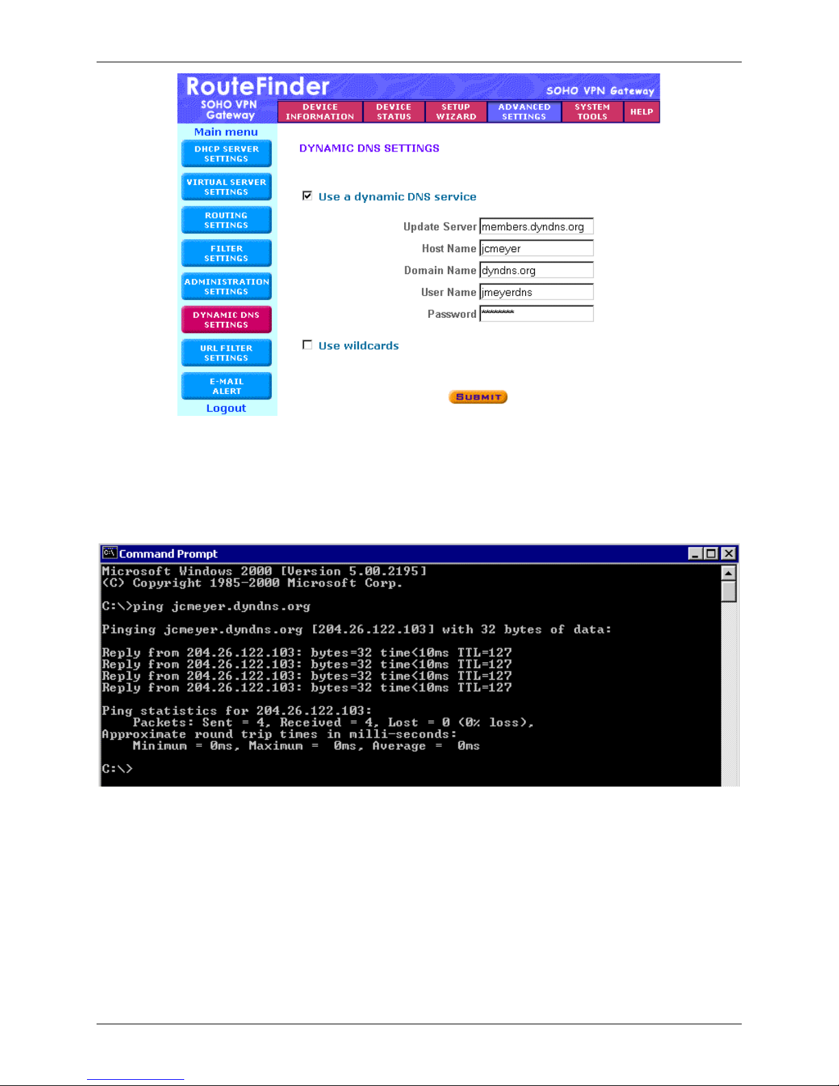
1.
To setup the RF550VPN/RF560VPN to support a Dynamic DNS, click the Dynamic DNS Settings
button on the left side of the Advanced Settings screen.
Place a check in the box for Use a dynamic DNS service.
2.
3.
Enter the name of your organization with the new DNS indicator. (Ex: members.dyndns.org)
yourname.dyndns.org or any other name in one of many domains offered by the
. This example will use dyndns.org as the service provider. The
4.
Enter the name of the Host Name in the DNS provider. This is the name you want the world to know
on the Internet. (Ex:
Note: Older versions of RF550VPN/RF560VPN firmware show the examples for
DNS Settings screen incorrectly. Version 4.62 firmware and above shows the notes for this screen
correctly.
Enter the Domain Name for the DNS provider. (Ex: dyndns.org)
5.
6.
Enter the user’s name and password, which is the account login name and password that was
created to login to the dyndns.org service. (Ex:
7.
If wildcards were specified when the Dynamic DNS was created, place a check in the box for Use
Wildcards. For this example wildcards is not enabled.
8.
Once the information has been entered, click on Submit. Then Save and Restart the
RF550VPN/RF560VPN.
jcmeyer)
NOTE2 on the Dynamic
jmeyerdns)
RF550VPN/RF560VPN Reference Guide – FQDN and DDNS Examples 3
Page 4
Multi-Tech Systems, Inc.
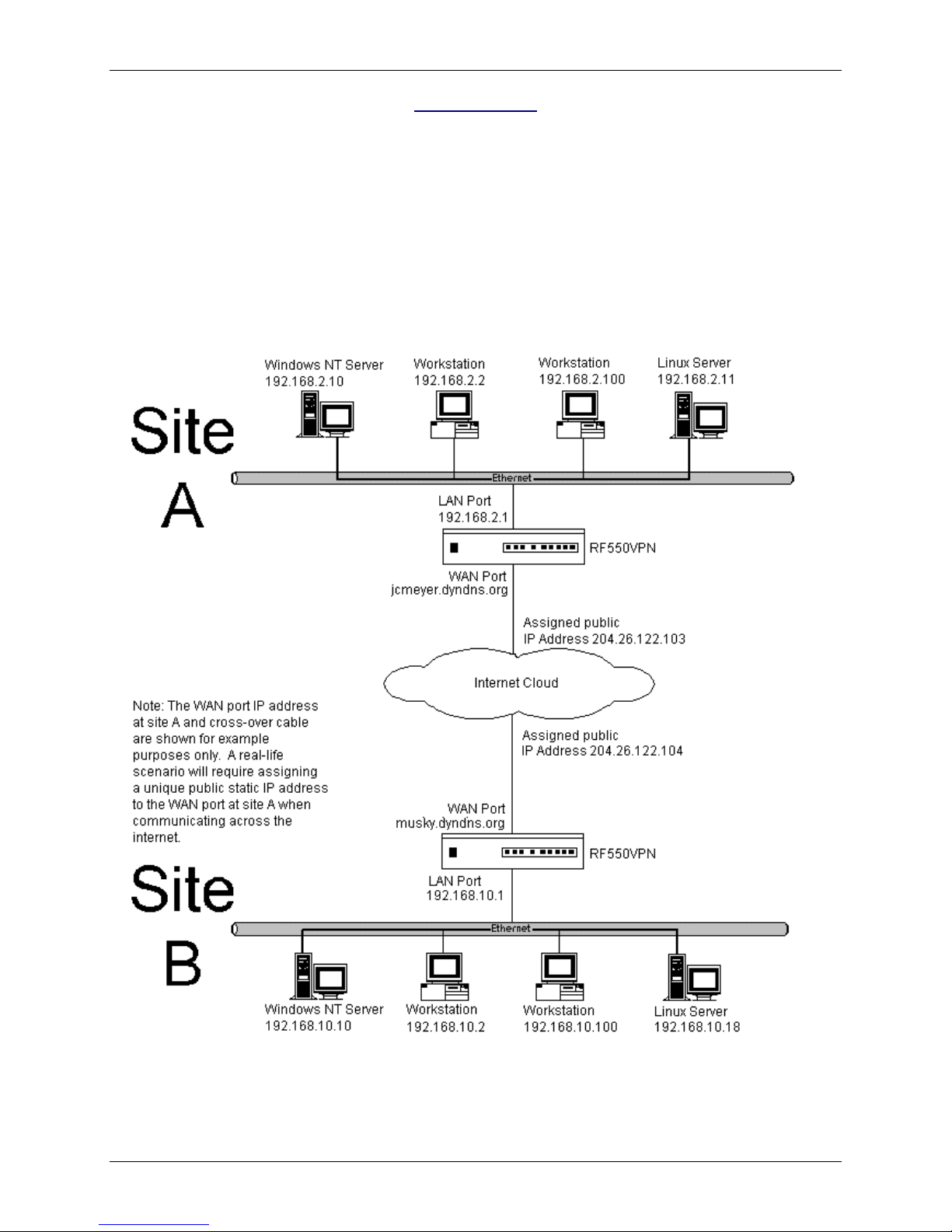
9. Once the RF550VPN/RF560VPN has restarted, test the Dynamic DNS by doing a PING to the
dynamic DNS from a computer on the Internet.
ping jcmeyer.dyndns.org
This ping should show a response from the IP address assigned to the created dynamic DNS.
RF550VPN/RF560VPN Reference Guide – FQDN and DDNS Examples 4
Page 5
Multi-Tech Systems, Inc.
Example 2
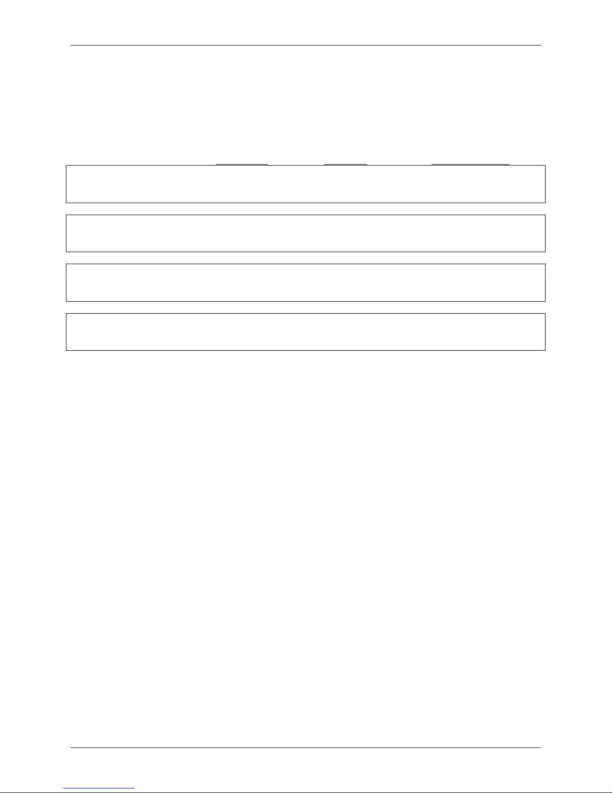
This example provides a sample RouteFinder configuration and related address scheme for an
application employing LAN-to-LAN IPSec VPN communication. This is an example on how to configure
an RF550VPN/RF560VPN at Site A and an RF550VPN/RF560VPN at Site B so Site A and B can
communicate through a secure connection over the Internet. This example assumes both VPN gateways
have fully qualified domain names and use dynamic DNS. This example does explain setting Secure
Association in the VPN Settings as IKE or Manual mode.
LAN-to-LAN FQDN & DDNS Configuration Diagram:
Note: The illustration labels the RouteFinder as the RF550VPN, but it stands for the RF560VPN also.
RF550VPN/RF560VPN Reference Guide – FQDN and DDNS Examples 5
Page 6

LAN-to-LAN Configuration Chart
Multi-Tech Systems, Inc.
LAN-to-LAN Application – Site A:
RF550VPN/RF560VPN
1. Domain name = Site-A.com
2. FQDN Hostname = jcmeyer.dyndns.org
3. SETUP WIZARD > DEVICE IP SETTINGS
IP Address: 192.168.2.1
IP Subnet Mask: 255.255.255.0
4. SETUP WIZARD > ISP SETTINGS
Select ‘Static IP Settings
IP assigned by your ISP: 204.26.122.103
IP Subnet Mask: 255.255.255.0
ISP Gateway Address: 204.26.122.1
5. SETUP WIZARD > VPN SETTINGS
Connection Name = SiteAtoB_FQDN
Check ‘Disable UID’
Check ‘Enable Keep Alive’
Do not check ‘Enabled NetBIOS Broadcast’
Remote Site = LAN
Remote IP Network = 192.168.10.0
Remote IP Netmask = 255.255.255.0
Remote Gateway IP/FQDN = musky.dyndns.org
Network Interface = WAN ETHERNET
Secure Association = check IKE (RF550)
Secure Association = check Main Mode (RF560)
Perfect Forward Secure = check enabled
Encryption Protocol = select 3DES
Preshared Key = (must match key code at Site B)
Key Life = set to default
IKE Life Time = set to default
LAN-to-LAN Application – Site B:
RF550VPN/RF560VPN
1. Domain name = Site-B.com
2. FQDN Hostname = musky.dyndns.org
3. SETUP WIZARD > DEVICE IP SETTINGS
IP Address: 192.168.10.1
IP Subnet Mask: 255.255.255.0
4. SETUP WIZARD > ISP SETTINGS
Select ‘Static IP Settings
IP assigned by your ISP: 204.26.122.104
IP Subnet Mask: 255.255.255.0
ISP Gateway Address: 204.26.122.1
5. SETUP WIZARD > VPN SETTINGS
Connection Name = SiteBtoA_FQDN
Check ‘Disable UID’
Check ‘Enable Keep Alive’
Do not check ‘Enabled NetBIOS Broadcast’
Remote Site = LAN
Remote IP Network = 192.168.2.0
Remote IP Netmask = 255.255.255.0
Remote Gateway IP/FQDN = jcmeyer.dyndns.org
Network Interface = WAN ETHERNET
Secure Association = check IKE (RF550)
Secure Association = check Main Mode (RF560)
Perfect Forward Secure = check enabled
Encryption Protocol = select 3DES
Preshared Key = (must match key code at Site A)
Key Life = set to default
IKE Life Time = set to default
RF550VPN/RF560VPN Reference Guide – FQDN and DDNS Examples 6
Page 7
Multi-Tech Systems, Inc.
Address Table
Enter the configuration information (e.g., the Default Gateway and other IP addresses used) into the
appropriate field of the Address Table below. Please print this page and use it to fill in your specific
RF550VPN/RF560VPN information and keep for future reference. (Example information below is shown
to match with the earlier diagram.)
IP Address Net Mask
Network Port connected
to the internal network ___.___.___.___ ___.___.___.___
(LAN ports) Site A 192.168.2.1 255.255.255.0
Network Port connected
to the external network ___.___.___.___ ___.___.___.___ ___.___.___.___
(WAN port) Site A 204.26.122.103 255.255.255.0 204.26.122.1
Network Port connected
to the internal network ___.___.___.___ ___.___.___.___
(LAN ports) Site B 192.168.10.1 255.255.255.0
Network Port connected
to the external network ___.___.___.___ ___.___.___.___ ___.___.___.___
(WAN port) Site B 204.26.122.104 255.255.255.0 204.26.122.1
LAN-to-LAN Application – Site A:
RF550VPN/RF560VPN
1. Domain name = __________
2. Public Class C = ___.___.___.X
LAN-to-LAN Application – Site B:
RF550VPN/RF560VPN
1. Domain name = __________
2. Public Class C = ___.___.___.X
Default Gateway
3. SETUP WIZARD > DEVICE IP SETTINGS
IP Address: ___.___.___.___
IP Subnet Mask: ___.___.___.___
4. SETUP WIZARD > ISP SETTINGS
IP assigned by your ISP: ___.___.___.___
IP Subnet Mask: 255.255.255.___
ISP Gateway Address: ___.___.___.___
5. SETUP WIZARD > VPN SETTINGS
Remote IP Network = ___.___.___.0
Remote IP Netmask = 255.255.255.0
Remote Gateway IP = ___.___.___.___
RF550VPN/RF560VPN Reference Guide – FQDN and DDNS Examples 7
Page 8
Multi-Tech Systems, Inc.
Software Configuration
Example 2: Configuration Procedure at Site A
1. Connect a workstation to one of the RF550VPN/RF560VPN’s LAN ports via Ethernet at Site A.
2.
Set the workstation IP address to 192.168.2.x subnet.
3. Apply power to the RF550VPN/RF560VPN RouteFinder and allow the LEDs to stabilize on the unit.
Bring up your web browser on the workstation. At the Web browser’s address line, type the Gateway
4.
address http://192.168.2.1 and press the Enter key.
Note: Make sure your workstation’s IP address is in the same network as the router’s address.
WINIPCFG and IPCONFIG are tools for finding a computer’s default gateway and MAC address. In
Windows 98/Me you can type WINIPCFG. In Windows 2000/NT, you can type IPCONFIG.
5.
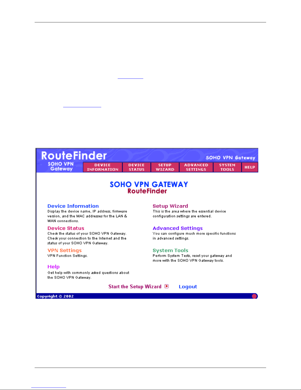
After typing the IP Address in the Web browser, the RF550VPN/RF560VPN main menu displays.
RF550VPN/RF560VPN Reference Guide – FQDN and DDNS Examples 8
Page 9

Multi-Tech Systems, Inc.
6. On the Main Menu, click the Setup Wizard button. The Password dialog box displays.
7.
Type admin (admin is the default user name) in the user name box and leave the password box
empty.
Note: To change your password after logging in, select the Advanced Settings button and
Administrative Settings.
8.
Click OK. The Setup Wizard screen displays a step-by-step process that lets you input all of the
basic settings to configure your RF550VPN/RF560VPN.
9.
Select the Time Zone, and then click the Next button to continue.
RF550VPN/RF560VPN Reference Guide – FQDN and DDNS Examples 9
Page 10

Multi-Tech Systems, Inc.
10. For Device IP Settings enter the internal LAN IP address and subnet mask that you want assigned
to the LAN ports of the RF550VPN/RF560VPN. This is not the IP address from your ISP but the local
internal LAN IP address. The default IP address is 192.168.2.1 and will be used for our example.
Device IP Address: 192.168.2.1.
Device IP Subnet Mask: 255.255.255.0
Click the Next button.
RF550VPN/RF560VPN Reference Guide – FQDN and DDNS Examples 10
Page 11

Multi-Tech Systems, Inc.
11. For ISP Settings, select Static IP Settings and enter the following information.
a) IP Assigned by your ISP: This is the IP address of the WAN port on the RF550VPN/RF560VPN
at Site A.
(Ex: 204.26.122.103)
b) IP Subnet Mask: This is the IP address of the subnet mask for the WAN port on the
RF550VPN/RF560VPN.
(Ex: 255.255.255.0)
c) IP Gateway Address: This is the IP address of the ISP Gateway at Site A. (Ex: 204.26.122.1)
Click the Next button.
Note: For this scenario it is not necessary to enter any information for the ISP Additional Settings or
Modem Settings.
RF550VPN/RF560VPN Reference Guide – FQDN and DDNS Examples 11
Page 12

Multi-Tech Systems, Inc.
12. Click the button on the left side of the screen for VPN Settings. Use this screen to setup your LAN-
to-LAN VPN connection.
13. For the RF550VPN: In the Connection Name field, type a name that identifies for you a connection
that you would like to make. (Ex: SiteAtoB_FQDN). Click the Add button.
For the RF560VPN: Select IPSec Settings and place a checkmark in the box for Enable IPSec
Function. In the Connection Name field, type a name that identifies for you a connection that you
would like to make. (Ex: SiteAtoB_FQDN). Click the Add button.
RF550VPN/RF560VPN Reference Guide – FQDN and DDNS Examples 12
Page 13

Multi-Tech Systems, Inc.
14. Two configuration choices are documented for Secure Association: IKE and Manual:
14a. The VPN Settings screen for entering specific VPN settings will display. The screen pictured
below assumes IKE is selected as the Secure Association. The Connection Name
(SiteAtoB_FQDN) defaults into the first field. Continue to enter the following settings:
a) Select Disable UID and leave Local IPSec Identifier and Remote IPSec Identifier blank.
b)
Check Enabled Keep Alive.
c)
Do not check Enabled NetBIOS Broadcast.
d)
Remote Site – Select LAN.
e)
Remote IP Network – Enter the Remote IP Network address (LAN) for Site B.
f)
(Ex: 192.168.10.0)
g) Remote IP Netmask – Enter the Remote IP Netmask address for Site B. (Ex:
255.255.255.0)
h)
Remote Gateway IP – Enter the Remote Gateway IP/FQDN hostname (WAN) for Site B.
Ex: musky.dyndns.org)
i)
Network Interface – Select the Network Interface from the drop-down list box. (Ex: WAN
Ethernet)
j)
Secure Association – For RF550VPN, select IKE to set how inbound packets will be filtered.
IKE is the default. IKE primarily encompasses router key exchange and the negotiation of
security policy. Selecting IKE will display the following fields. For RF560VPN, select Main
Mode for RF560VPN.
k)
Perfect Forward Secure – Check the Enabled button.
RF550VPN/RF560VPN Reference Guide – FQDN and DDNS Examples 13
Page 14

Multi-Tech Systems, Inc.
l) Encryption Protocol – Select the encryption protocol used for your configuration. The
default protocol for the RF550VPN/RF560VPN communicating with another
RF550VPN/RF560VPN is 3DES. (Ex: 3DES)
m)
PreShared Key – Enter the PreShared Key name (you can enter an alphanumeric name but
it needs to match the security code for the RouteFinder at site B).
n)
Key Life – Enter the amount of time that tells the router to renegotiate the Key. For example,
28800 seconds is 8 hours.
o)
IKE Life Time – Enter the amount of time that tells the router to renegotiate the IKE security
association. For example, 3600 seconds is 60 minutes.
14b. The screen pictured below assumes Manual is selected as the Secure Association on the VPN
Settings screen. The Connection Name (SiteAtoB_FQDN) defaults into the first field. Continue
to enter the following settings:
Note: If Secure Association is set to Manual, the two RF550VPN/RF560VPNs must
communicate with Static IP addresses at both ends.
Note: Enter all data for a) through i) as illustrated above when running in IKE mode. Then complete
the following steps:
j)
Secure Association – Selecting Manual instead of IKE will set how inbound packets will be
filtered and then the following fields display.
k)
Incoming SPI – Enter the incoming SPI that the remote VPN gateway, at Site B, will use to
identify this Security Association. Enter a three-digit number between 100 and 400. This value
must match the outgoing SPI value entered at the remote VPN gateway at Site B. (Ex: 400)
l)
Outgoing SPI – Enter the outgoing SPI that the Site A VPN gateway will use to identify this
Security Association. Enter a three-digit number between 100 and 400. This value must match
the incoming SPI value entered at the remote VPN gateway at Site B. (Ex: 100)
Encryption Protocol – Select an appropriate encryption algorithm: Null, DES, 3DES. 3DES is
m)
the recommended choice.
n)
Encryption Key – Enter a string of characters to be used to encrypt and decrypt transmitted
data between the two RouteFinders. The string is made up of 24 alphanumeric characters and
needs to match the Encryption Key for the RouteFinder at Site B. (Ex:
123456789012345678901234)
o)
Authentication Protocol – Select an appropriate authentication algorithm: MD5 or SHA-1.
MD5 is the recommended choice.
p)
Authentication Key – Enter a string of characters to be used as a key for authentication
between the two RouteFinders. The string is similar to a password and is made up of 16
alphanumeric characters and needs to match the Authentication Key for the VPN at Site B.
(Ex: 1234567890123456)
15.
Once the VPN settings are entered, click on the Save button. The Connection Name will display on
the lower half of the screen and on the initial VPN Settings screen. You can enable/disable, edit, or
delete this connection by clicking the corresponding buttons. To enable this connection, check the
Enable box that appears to the left of the connection name.
Note: If you uncheck the Enable box, the parameters will remain in the table for you to
enable/disable, edit, or delete at any time.
RF550VPN/RF560VPN Reference Guide – FQDN and DDNS Examples 14
Page 15

Multi-Tech Systems, Inc.
16. After you have finished making all the changes on the various pages, click Save and Restart to save
the settings and restart the device. After the restart, the device will function according to the saved
settings.
17. During the save and restart process, system messages will let you know that you have successfully
configured the settings for the device and saved the settings. You will see a status bar across the
bottom of your browser showing the progress of the startup process. The RouteFinder home page will
be loaded automatically after restart is completed.
This completes the configuration of the RF550VPN/RF560VPN at Site A. Now move to Site B and
configure that RF550VPN/RF560VPN, from a workstation through one of its LAN ports, as done for
RF550VPN/RF560VPN Reference Guide – FQDN and DDNS Examples 15
Site A.
Page 16

Multi-Tech Systems, Inc.
Configuration Procedure at Site B
1. Connect a workstation to one of the RF550VPN/RF560VPN’s LAN ports via Ethernet for Site B.
Note: It is assumed that the IP Address of the RouteFinder’s LAN at Site B (Ex: 192.168.10.1) has
already been changed from it’s default (192.168.2.1) so it does not conflict with the IP Address of the
RouteFinder’s LAN at Site A (Ex: 192.168.2.1).
Set the workstation IP address to 192.168.10.x subnet.
2.
3. Apply power to the RF550VPN/RF560VPN RouteFinder and allow the LEDs to stabilize on the unit.
4.
Bring up your web browser on the workstation. At the web browser’s address line, type the Gateway
address http://192.168.10.1 and press the Enter key.
Note: Make sure your workstation’s IP address is in the same network as the router’s address.
WINIPCFG and IPCONFIG are tools for finding a computer’s default gateway and MAC address. In
Windows 98/Me you can type WINIPCFG. In Windows 2000/NT, you can type IPCONFIG.
After typing the IP Address in the web browser, the RF550VPN/RF560VPN main menu displays.
5.
RF550VPN/RF560VPN Reference Guide – FQDN and DDNS Examples 16
Page 17

Multi-Tech Systems, Inc.
6. On the Main Menu, click the Setup Wizard button. The Password dialog box displays.
7.
Type admin (admin is the default user name) in the user name box and leave the password box
empty.
Note: To change your password after logging in, select the Advanced Settings button and
Administrative Settings.
8.
Click OK. The Setup Wizard screen displays a step-by-step process that lets you input all of the
basic settings to configure your RF550VPN/RF560VPN.
Select the Time Zone, and then click the Next button to continue.
9.
RF550VPN/RF560VPN Reference Guide – FQDN and DDNS Examples 17
Page 18

Multi-Tech Systems, Inc.
10. For Device IP Settings enter the internal LAN IP address and subnet mask that you want assigned
to the LAN ports of the RF550VPN/RF560VPN. This is not the IP address from your ISP but the local
internal LAN IP address. The default IP address is 192.168.2.1 but for our example we will use
192.168.10.1.
Device IP Address: 192.168.10.1.
Device IP Subnet Mask: 255.255.255.0
Click the Next button.
RF550VPN/RF560VPN Reference Guide – FQDN and DDNS Examples 18
Page 19

Multi-Tech Systems, Inc.
11. For ISP Settings, check the box Your ISP requires you to input IP settings’ and enter the following
information.
a)
IP Assigned by your ISP: This is the IP address of the WAN port on the RF550VPN/RF560VPN
at Site B.
(Ex: 204.26.122.104)
b)
IP Subnet Mask: This is the IP address of the subnet mask for the WAN port on the
RF550VPN/RF560VPN at Site B. (Ex: 255.255.255.0)
IP Gateway Address: This is the IP address of the ISP Gateway at Site B.
c)
(Ex: 204.26.122.1)
Click the Next button.
Note: For this scenario it is not necessary to enter any information for the ISP Additional Settings
or Modem Settings.
RF550VPN/RF560VPN Reference Guide – FQDN and DDNS Examples 19
Page 20

Multi-Tech Systems, Inc.
12. Click the button on the left side of the screen for VPN Settings. Use this screen to setup your LANto-LAN VPN connection.
For the RF550VPN: In the Connection Name field, type a name that identifies for you a connection
13.
that you would like to make. (Ex: SiteBtoA_FQDN). Click the Add button.
For the RF560VPN: Select IPSec Settings and place a checkmark in the box for Enable IPSec
Function. In the Connection Name field, type a name that identifies for you a connection that you
would like to make. (Ex: SiteBtoA_FQDN). Click the Add button.
RF550VPN/RF560VPN Reference Guide – FQDN and DDNS Examples 20
Page 21

Multi-Tech Systems, Inc.
14. Two configuration choices are documented for Secure Association: IKE and Manual:
14a. The VPN Settings screen for entering specific VPN settings will display. The screen pictured
below assumes IKE is selected as the Secure Association. The Connection Name
(SiteBtoA_FQDN) defaults into the first field. Continue to enter the following settings:
a) Select Disable UID and leave Local IPSec Identifier and Remote IPSec Identifier blank.
b)
Do not check Enabled Keep Alive.
c)
Do not check Enabled NetBIOS Broadcast.
d) Remote Site – Select LAN.
e)
Remote IP Network – Enter the Remote IP Network address (LAN) for Site A. (Ex:
192.168.2.0)
f)
Remote IP Netmask – Enter the Remote IP Netmask address for Site A. (Ex: 255.255.255.0)
g)
Remote Gateway IP – Enter the Remote Gateway IP/FQDN hostname address (WAN) for
Site A. (Ex: jcmeyer.dyndns.org)
h)
Network Interface – Select the Network Interface from the drop-down list box. (Ex: WAN
Ethernet)
i)
Secure Association – For the RF550VPN, select IKE to set how inbound packets will be
filtered. IKE is the default. IKE primarily encompasses router key exchange and the
negotiation of security policy. Selecting IKE displays the following fields. For the RF560VPN,
select Main Mode.
j)
Perfect Forward Secure – Check the Enabled button.
RF550VPN/RF560VPN Reference Guide – FQDN and DDNS Examples 21
Page 22

Multi-Tech Systems, Inc.
k) Encryption Protocol – Select the encryption protocol used for your configuration. The default
protocol for the RF550VPN/RF560VPN communicating with another RF550VPN/RF560VPN is
3DES. (Ex: 3DES)
l)
PreShared Key – Enter the PreShared Key name (you can enter an alphanumeric name but it
needs to match the security code for the RouteFinder at Site A. (Ex: test).
m)
Key Life – Enter the amount of time that tells the router to renegotiate the Key. For example,
28800 seconds is 8 hours.
n)
IKE Life Time – Enter the amount of time that tells the router to renegotiate the IKE security
association. For example, 3600 seconds is 60 minutes.
14b. The VPN Settings screen for entering specific VPN settings will display. The screen pictured below
assumes Manual is selected as the Secure Association. The Connection Name
(SiteBtoA_FQDN) defaults into the first field. Continue to enter the following settings:
Note: If Secure Association is set to Manual, the two RF550VPN/RF560VPNs must
communicate with Static IP addresses at both ends.
Note: Enter all data for a) through i) as illustrated above when running in IKE mode. Then complete
the following steps.
j)
Secure Association – Selecting Manual instead of IKE will set how inbound packets will be
filtered. Selecting Manual displays the following fields
k)
Incoming SPI – Enter the incoming SPI that the remote VPN at Site B will use to identify this
Security Association. Enter a three-digit number between 100 and 400. This value must
match the outgoing SPI value entered at the remote VPN gateway at Site A. (Ex: 100)
Outgoing SPI – Enter the outgoing SPI that the Site B VPN gateway will use to identify this
l)
Security Association. Enter a three-digit number between 100 and 400. This value must
match the incoming SPI value entered at the remote VPN gateway at Site A. (Ex: 400)
m)
Encryption Protocol – Select an appropriate encryption algorithm: Null, DES, 3DES. 3DES
is the recommended choice.
n)
Encryption Key – Enter a string of characters to be used to encrypt and decrypt transmitted
data between the two VPNs. The string is made up of 24 alphanumeric characters and
needs to match the Encryption Key for the RouteFinder at Site A. (Ex:
123456789012345678901234)
o)
Authentication Protocol – Select an appropriate authentication algorithm: MD5 or SHA-1.
MD5 is the recommended choice.
p)
Authentication Key – Enter a string of characters to be used as a key for authentication
between the two VPNs. The string is similar to a password and is made up of 16
alphanumeric characters and needs to match the Authentication Key for the VPN at Site A.
(Ex: 1234567890123456)
15. Once the VPN settings are entered, click on the Save button, the Connection Name will display on
the lower half of the screen and on the initial VPN Settings screen. You can enable/disable, edit, or
delete this connection by clicking the corresponding buttons. To enable this connection, check the
Enable box that appears to the left of the connection name.
RF550VPN/RF560VPN Reference Guide – FQDN and DDNS Examples 22
Page 23

Multi-Tech Systems, Inc.
Note: If you uncheck the Enable box, the parameters will remain in the table for you to
enable/disable, edit, or delete at any time.
16. After you have finished making all the changes on the various pages, click Save and Restart to save
the settings and restart the device. After the restart, the device will function according to the saved
settings.
During the save and restart process, system messages will let you know that you have successfully
configured the settings for the device and saved the settings. You will see a status bar across the
bottom of your browser showing the progress of the startup process. The RouteFinder home page will
be loaded automatically after restart is completed.
This completes the configuration of the RF550VPN/RF560VPN at Site B.
RF550VPN/RF560VPN Reference Guide – FQDN and DDNS Examples 23
Page 24

Multi-Tech Systems, Inc.
Testing Your Configuration
You can test your connection between the two RouteFinders using the PING command at a DOS prompt.
At the Site A workstation connected to a LAN port of the RF550VPN/RF560VPN:
1.
a)
At the DOS prompt PING a workstation connected to the LAN port of the RF550VPN/RF560VPN
at Site B.
Example: PING 192.168.10.18 <return>
You should see four successful packet transmit/receive statements. If you do not, try several
more times. You may see several initial failures while the two RouteFinders make a secure
connection.
If this fails, try to PING the WAN port of the RF550VPN/RF560VPN at Site B.
b)
Example: PING 204.26.122.104
You should see four successful packet transmit/receive statements. If you do not, try several
more times. You may see several initial failures while the two RouteFinders make a secure
connection.
If this fails, try to PING the WAN port of the RF550VPN/RF560VPN at Site A.
c)
Example: PING 204.26.122.103
Note: If any of these tests fail then verify that the workstation is connected to the LAN port of the
RF550VPN/RF560VPN. The LAN port LINK LED should be on and the ACT LED should blink on
each time you PING the RF550VPN/RF560VPN. Verify the WAN port at each Site is connected
properly. Also verify that the RF550VPN/RF560VPN is configured properly.
2.
At the Site B workstation connected to a LAN port of the RF550VPN/RF560VPN:
At the DOS prompt PING a workstation connected to the LAN port of the RF550VPN/RF560VPN
a)
at Site A.
Example: PING 192.168.2.100 <return>
You should see four successful packet transmit/receive statements. If you do not, try several
more times. You may see several initial failures while the two RouteFinders make a secure
connection.
b)
If this fails, try to PING the WAN port of the RF550VPN/RF560VPN at Site A.
Example: PING 204.26.122.103
You should see four successful packet transmit/receive statements. If you do not, try several
more times. You may see several initial failures while the two RouteFinders make a secure
connection.
c)
If this fails, try to PING the WAN port of the RF550VPN/RF560VPN at Site B.
Example: PING 204.26.122.104
Note: If any of these tests fail then verify that the workstation is connected to a LAN port of the
RF550VPN/RF560VPN. The LAN port LINK LED should be on and the ACT LED should blink on
each time you PING the RF550VPN/RF560VPN. Verify the WAN port at each Site is connected
properly. Also verify that the RF550VPN/RF560VPN is configured properly.
RF550VPN/RF560VPN Reference Guide – FQDN and DDNS Examples 24
(S000313B 08/06/03)
 Loading...