

Page 1
Model RF500S
DSL/Cable Router
with Built-in 4-port 10/100 Switch
Quick Start Guide
Page 2

Quick Start Guide
PN#82099150
Model RF500S DSL/Cable Router
This publication may not be reproduced, in whole or in part, without prior
expressed written permission from Multi-Tech Systems, Inc. All rights
reserved.
Copyright © 2000, by Multi-Tech Systems, Inc.
Multi-Tech Systems, Inc. makes no representations or warranties with
respect to the contents hereof and specifically disclaims any implied
warranties of merchantability or fitness for any particular purpose.
Furthermore, Multi-Tech Systems, Inc. reserves the right to revise this
publication and to make changes from time to time in the content hereof
without obligation of Multi-Tech Systems, Inc. to notify any person or
organization of such revisions or changes.
Record of Revisions
Revision Description
A
(8/04/00) Manual released. All pages at software Version 7.1
Patents
This Product is covered by one or more of the following U.S. Patent
Numbers:
5.301.274; 5.309.562; 5.355.365; 5.355.653; 5.452.289;
5.453.986
. Other Patents Pending.
TRADEMARK
Trademark of Multi-Tech Systems, Inc. is the Multi-Tech logo.
Windows is a registered trademark of Microsoft.
Multi-Tech Systems, Inc.
2205 Woodale Drive
Mounds View, Minnesota 55112
(612) 785-3500 or (800) 328-9717
Fax (612) 785-9874
Tech Support (800) 972-2439
Internet Address: http://www.multitech.com
Page 3

iii
Contents
Introduction ................................................................................... 4
Related Documentation................................................................. 5
Get Adobe Acrobat Reader..................................................... 5
Get the User Guide................................................................. 5
Save or Print the User Guide.................................................. 5
Hardware Installation..................................................................... 6
Safety Warnings ..................................................................... 6
Unpacking your RouteFinder .................................................. 6
Cabling your RouteFinder ....................................................... 7
Software Installation and Configuration......................................... 9
Using RouteFinder Setup Wizard ......................................... 10
Testing your Connection ....................................................... 28
Using Telnet to Configure your RouteFinder......................... 29
Limited Warranty ......................................................................... 33
Service ........................................................................................ 33
Page 4
RouteFinder RF500S Quick Start Guide
4
Introduction
Congratulations on the purchase of one of the finest
broadband routers available today, Multi-Tech System’s
RouteFinder Model RF500S.
The RouteFinder connects a cable or DSL modem to an
Ethernet LAN to provide high-speed broadband access to the
Internet for up to 253 LAN clients using only 1 IP account. The
RF500S features an integrated 4-port 10/100 switch for LAN
access, one asynchronous port that acts as a backup
resource for Internet access or serves as dial-in remote
access for telecommuters or mobile users. The RouteFinder
RF500S uses the NAT protocol to implement firewall and
gateway security for LAN-based resources. For added LAN
security, the RouteFinder can be used to segment the LAN.
This solution is ideal for any small business looking for cost-
effective broadband access to the Internet for every LAN client
on the LAN or for the home user looking to share their DSL
cable modem.
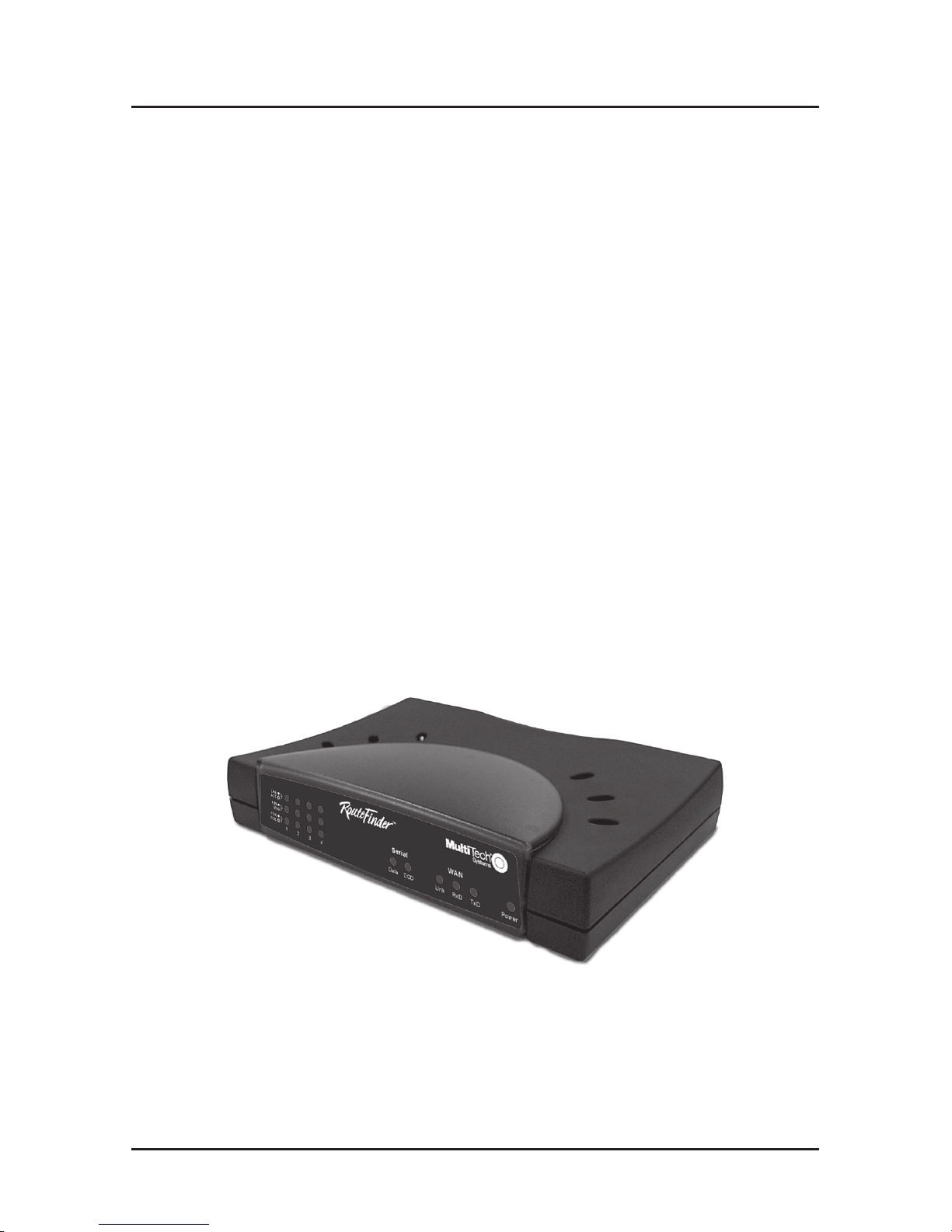
The RouteFinder RF500S
Page 5

Introduction
5
Related Documentation
This RF500S DSL/Cable Router Quick Start Guide is intended
to be used by systems administrators and network managers.
This guide provides the necessary information for a qualified
person to unpack, cable, install software, and configure the
device for proper operation.
A detailed RF500S DSL/Cable Router User Guide in Adobe
Acrobat PDF format is provided on the System CD included
with your RouteFinder RF500S. The User Guide provides in-
depth information on the features and functions available on
your router .
Get Adobe Acrobat Reader
Adobe Acrobat Reader is a free program used to view
documents created in Adobe PDF format. Adobe Acrobat
Reader can be installed from the System CD (click on the
Install Manuals option and select Install Adobe Acrobat
Reader) or downloaded from Adobe’s Web site at:
http://www.adobe.com/prodindex/acrobat/readstep.html
Get the User Guide
The User Guide can be installed from the System CD by
clicking Install Manuals on the Installation screen or
downloading the file from our Web site at: http://
www .multitech.com
Save or Print the User Guide
Once the User Guide is displayed on screen using Adobe
Acrobat Reader , you can save the .pdf file to your system or
print a copy.
Page 6

RouteFinder RF500S Quick Start Guide
6
Hardware Installation
Safety Warnings
1. Never install telephone wiring during a lightning storm.
2. Never install telephone jacks in a wet location unless the
jack is specifically designed for wet locations.
3. This product is to be used with UL and cUL listed
computers.
4. Never touch uninsulated telephone wires or terminals
unless the telephone line has been disconnected at the
network interface.
5. Avoid using a telephone (other than a cordless type)
during an electrical storm. There may be a remote risk of
electrical shock from lightening.
7. Do not use the telephone to report a gas leak in the vicinity
of the leak.
8. To reduce the risk of fire, use only No. 26 AWG or larger
Telecommunications line Cord.
Unpacking your RouteFinder
The RF500S shipping box contains the following items:
• System CD
• Tucows CD
• Power Supply
• The RouteFinder RF500S
• This Quick Start Guide
• A serial cable
If any of the items is missing or damaged, please contact
Multi-Tech Systems.
Page 7

Hardware Installation
7
Cabling your RouteFinder
Cabling your RouteFinder requires making the appropriate
connections to PCs, Cable or DSL modem, analog modem or
ISDN TA (optional), AC power and the router. Because this
device also provides DHCP server functions, remote access,
routing and firewall protection, after your device is properly
cabled, you will need to complete your configuration by
following the instructions provided in the Software Installation
and Configuration section of this Quick Start Guide.
10/100 BT LAN
Uplink/Normal
1234
ASYNC
Reset
10 BT WAN
5VDC
Power
Optional
Uplink
Serial Cable
To Cable Modem
or DSL Modem
Power Connection
To optional
Modem or
ISDN TA
Network Printer
Hub
PC
PC
Cabling the RouteFinder RF500S
1. Before beginning, turn the power off on all network devices
(PCs, Cable, DSL modems, analog modems, ISDN TAs
and the router).
2. Connect the Ethernet port of each PC or network device to
one of the 4 LAN ports (if you are using the Uplink option,
port number 1 cannot be used as a LAN port).
Page 8

RouteFinder RF500S Quick Start Guide
8
3. If you are using an analog modem, connect it to the Serial
Async port.
4. To use the Uplink option to connect to another network
segment, slide the
Uplink/Normal
switch into the Uplink
position. Connect the LAN cable to LAN port number 1.
Plug the other end of the LAN cable into another hub,
router or switch.
Note: If you are not using the Uplink feature, place the
switch in the
Normal
position.
5. Connect a network cable from the DSL or Cable modem to
the WAN port.
6. Connect the provided power supply cable to the 5VDC
power port on the back of the router . Plug the power
supply into an AC power outlet as shown.
7. Power on your DSL modem or Cable.
8. If you are using an analog modem or ISDN TA, power on
the device.
9. Press and hold the RouteFinder’s Reset button for 3
seconds to restore the default settings.
10. You are ready to configure software for your router and
network PCs.
Page 9

Software Installation
9
Software Installation and Configuration
Before beginning the installation process, ensure that your
system meets all hardware and software requirements:
• Intel 486 or higher processor .
• 10/100 BaseT cable to connect the RF500S to the
network.
• One DSL or Cable Modem.
• A networked computer with Windows 95/98/2000,
Windows NT 3.5 or higher and TCP/IP protocol installed,
(Or , a non-Windows system with TCP/IP properly installed
to enable Telnet configuration).
• Any Windows communication application for Dial-Out
operation.
• Any PPP supported communication application for Dial-In
operation.
• TCP/IP installed and configured on each workstation
accessing the Internet.
Software Installation
The software installation process involves installing the
RouteFinder Utilities, including RouteFinder Setup Wizard,
RouteFinder Manager and RouteFinder Monitor . A description
of each component follows:
RouteFinder Setup Wizard
The RouteFinder Setup Wizard provides a step-by-step
process to assist you in entering all the basic settings needed
to configure your RF500S for general use. All settings that are
entered in the Setup Wizard can be found in their respective
menus in RouteFinder Manager .
Page 10

RouteFinder Quick Start Guide
10
RouteFinder Manager
RouteFinder Manager is the main program used to configure
all settings for your RF500S. Complete information about
options within the RouteFinder Manager can be found in the
User Guide.
RouteFinder Monitor
RouteFinder Monitor is a multi-purpose utility designed to let
you know the status of your RF500S connection. The monitor
offers the ability to point and click on an event to access
context-sensitive troubleshooting procedures. Refer to the
User Guide for more information about RouteFinder Monitor .
Using RouteFinder Setup Wizard
Note: Before beginning this procedure, ensure that your
RF500S is properly connected to the network and the device is
powered on.
After installing the software, you may return to the
RouteFinder Setup Wizard, by clicking Start | Programs |
RouteFinder Manager | RouteFinder Wizard.
Before running the Setup Wizard, it is strongly recommended
that you exit all Windows programs.
1. Insert the RF500S System CD into your computer’s CDROM drive. The RF500S System CD screen appears.
Note: If Autorun is disabled on your computer, use
Windows Explorer to view the contents of the CD.
Double-click the CD icon to display the RF500S System
CD main screen.
2. Click Install Software.
3. Follow the on-screen instructions to install the software.
Page 11
Software Installation
11
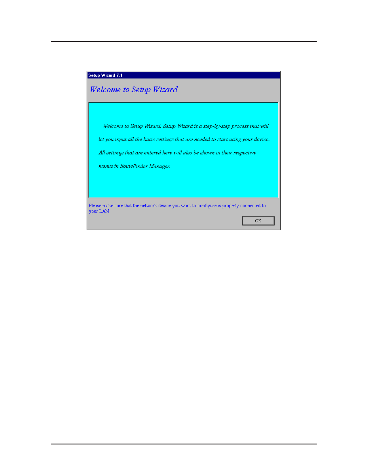
4. When the software installation completes, the Setup
Wizard dialog box displays.
Click OK.
Page 12
RouteFinder Quick Start Guide
12
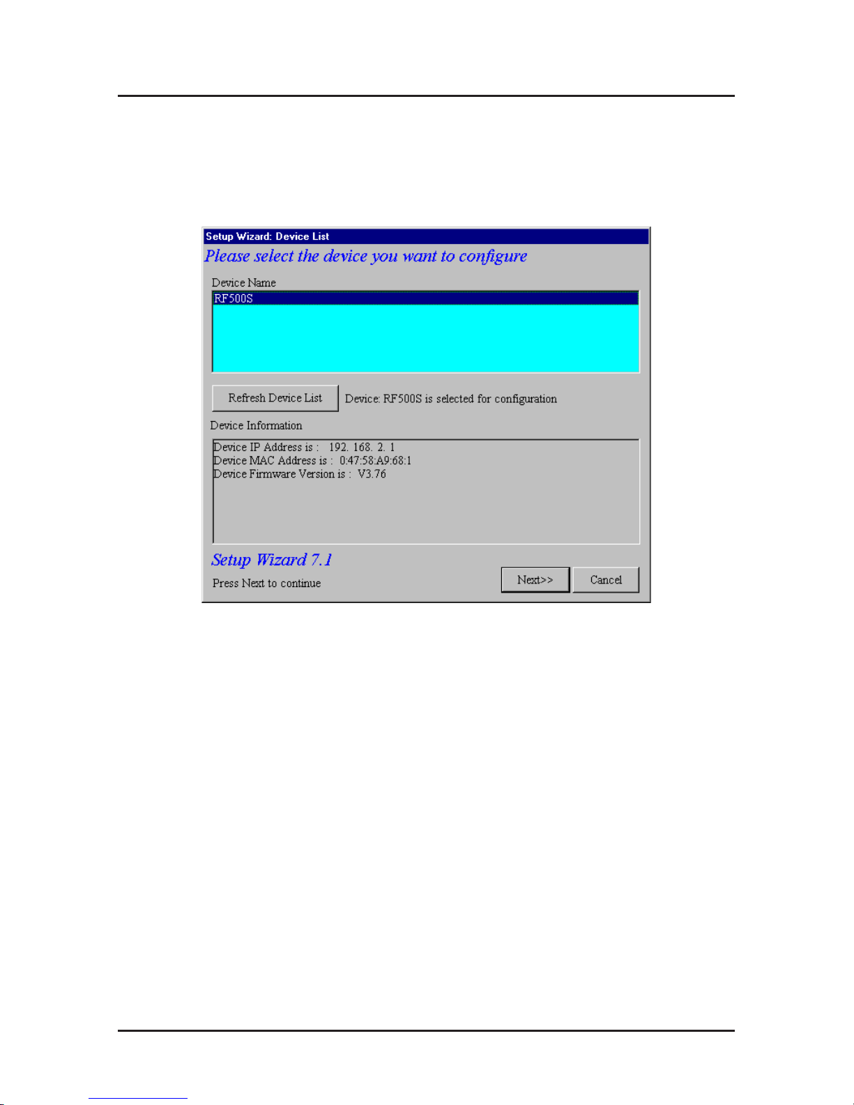
5. The Setup Wizard: Device List dialog box displays. The
Setup Wizard automatically checks your network for
available network devices and displays them on the
screen.
Select the device you wish to configure from the Device
Name list.
Record the values presented in the Device Information
panel for later reference.
Device IP Address
______________________
Device MAC Address
____________________
Device Firmware Version
_________________
Click Next>>.
Note: If a message appears indicating the device is not
found, or you do not see the device you are attempting to
configure listed, click the Refresh Device List button.
Page 13
Software Installation
13
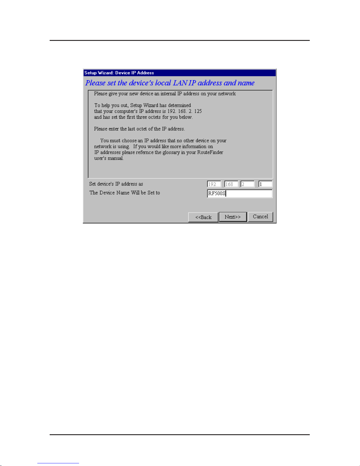
6. The Setup Wizard: Device IP Address dialog box
displays.
Enter your local internal network’s IP address for this
device.
The Setup Wizard will automatically detect the first three
octets of your local IP address. You must enter the last
octet only .
If you wish, you can change the network name of your
RouteFinder . If you are connecting to an ISP, the device
name can act as your computer name if it is required on
the remote system.
Click Next>> to continue. The device will search the
network to ensure that the IP address is valid. This may
take several seconds.
Note: If your ISP provided you with an IP address, do not
enter that address in this field. Enter the IP address for
this device on your local network. Refer to the Glossary in
the User Guide for additional information on IP addressing.
Page 14
RouteFinder Quick Start Guide
14
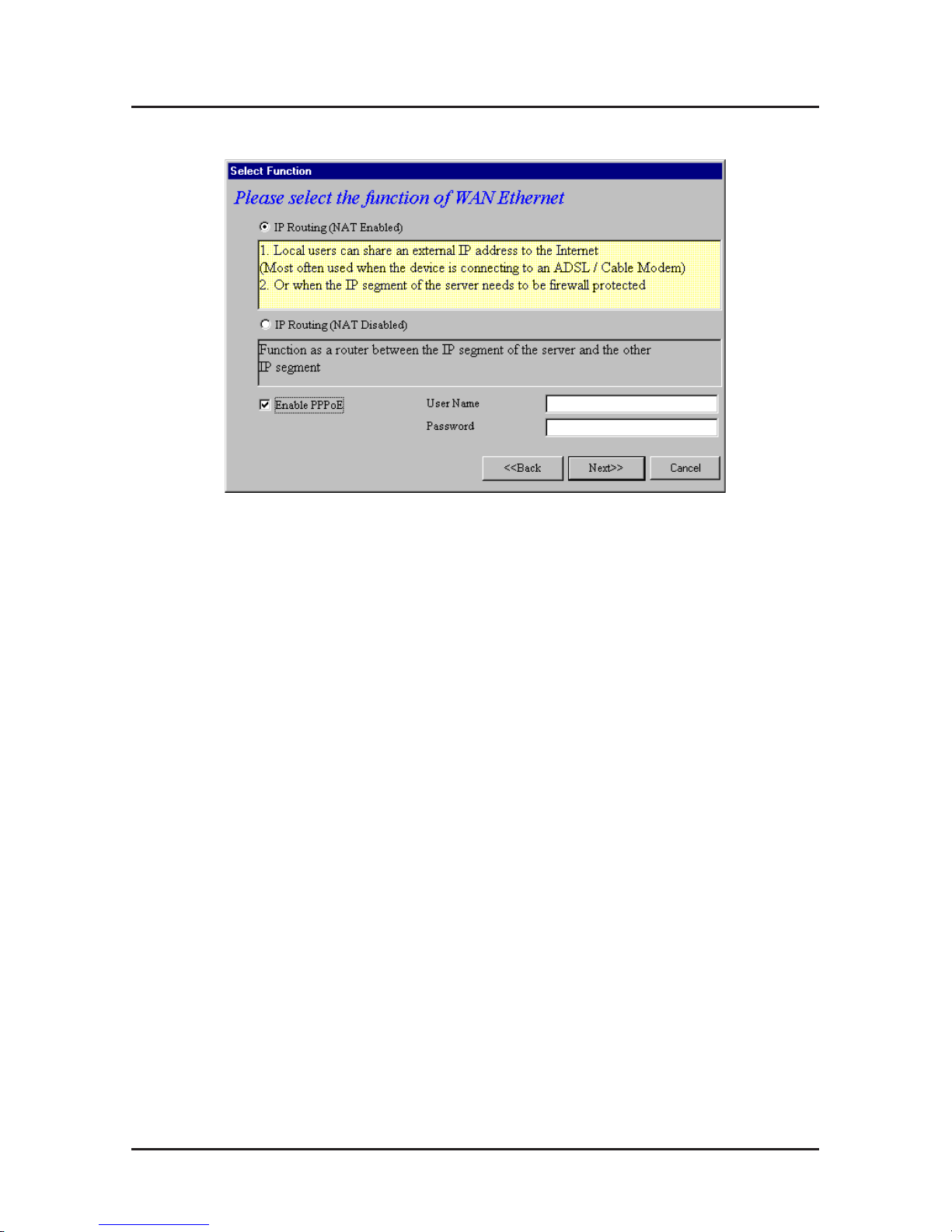
7. The Select Function dialog box displays.
Select the function of the WAN Ethernet port by selecting
IP Routing (NAT Enabled), IP Routing (NAT Disabled
. If
you are using NAT Enabled, you may also select
Enable
PPPoE
.
• Select
IP Routing (NAT Enabled)
to allow local LAN clients
to share one external IP address for accessing the
Internet. This option is most often used when the RF500S
is connected to a DSL or cable modem, or when the IP
segment of the server needs firewall protection.
• Select
IP Routing (NAT Disabled)
to allow the RF500S to
function as a router between the IP segment of the server
and another IP segment. This option is ideal for
organizations needing to segment workgroups.
• Select
Enable PPPoE
to use the RF500S with a timebase, rather than fixed-cost DSL modem connection. Enter
the User Name and Password provided by your ISP. This
option is most often used when connecting via DSL to the
Internet.
Note: Enable PPPoE is valid only when IP Routing (NAT
Enabled) is selected.
Click Next>>.
Page 15
Software Installation
15
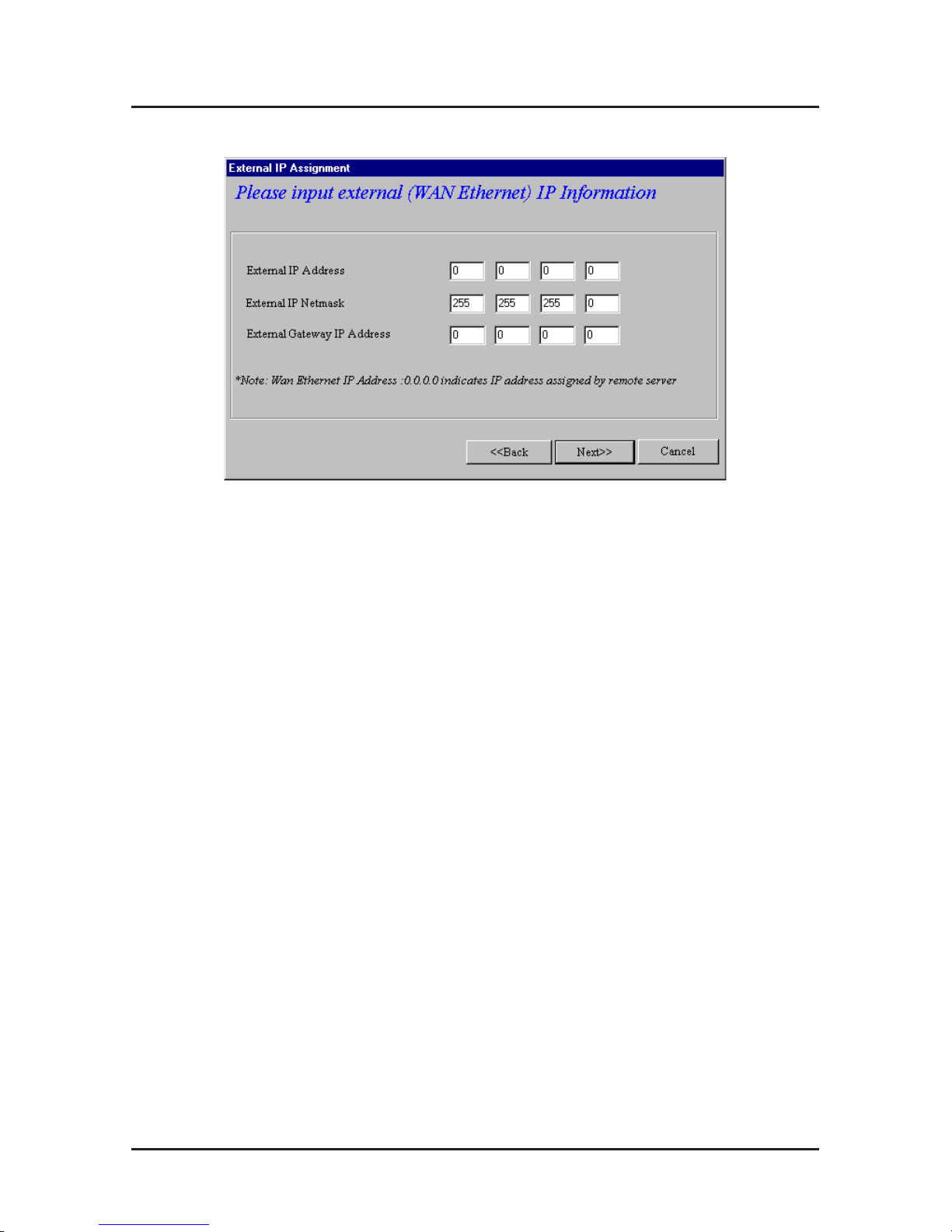
8. The External IP Assignment dialog box displays.
Enter the WAN Ethernet IP address information
provided
by your ISP
or
other external network administrator
.
• In the
External IP Address
box, enter the ISP or remote
system’s IP address.
• In the
External IP Netmask
box, enter the ISP or remote
system’s IP segment netmask (for Class C networks, the
Netmask is generally set to 255.255.255.0).
• In the
External Gateway IP Address
box, enter the IP
address of the ISP or remote network’s Gateway to their
network.
Note: If your ISP uses dynamic IP addressing, leave the
External IP address and the External Gateway IP address
at the default values of 0.0.0.0. Set the External IP
Netmask to the default value of 255.255.255.0.
Click Next>>.
Page 16
RouteFinder Quick Start Guide
16
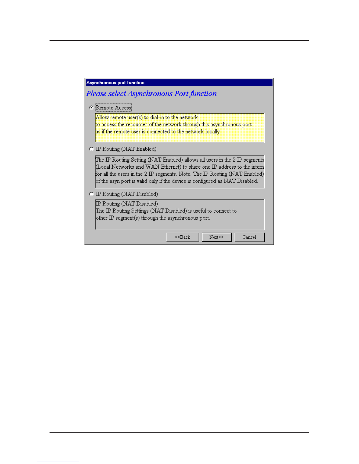
9. The Asynchronous Port Function dialog box displays.
Select 1.) Remote Access, 2.) IP Routing (NA T
Enabled) or 3.) IP Routing (NAT Disabled).
• Select
Remote Access
to allow remote users to dial-in to
the network to access resources as if the remote user is
connected to the network locally.
Continue with the
Remote Access instructions on page 17.
• Select
IP Routing (NAT Enabled)
to allow all users in the
two IP segments (LAN and W AN Ethernet) to share one IP
address to the Internet. You may also select this option to
use the async port for dial-up backup in the event the DSL
or cable becomes unavailable.
Note: The IP Routing (NAT Enabled) feature of the async
port is valid only if the
WAN
port is configured as
NAT
Disabled
.
• Select
IP Routing (NAT Disabled)
to connect other IP
segments through the async port.
Proceed to the IP
Routing instructions on page 20.
Click Next>>.
Page 17
Software Installation
17
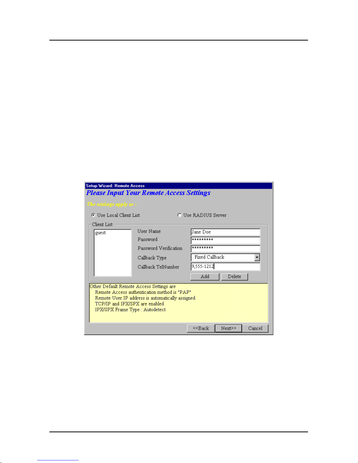
1.) Remote Access
You must define the location of your remote user account
database by selecting a)
Use Local Client List
or b)
Use
RADIUS Server.
Follow the instructions for the user
database your system will use..
Note: The Local Client List allows you to add a maximum
of 64 users.
a.) Use Local Client List
Use Local Client List allows you to create an
authentication database consisting of user names,
passwords and dial-in options for each remote user . You
must provide the following information for each client:
User Name: Enter the User Name to authenticate the
remote dial-in user .
Password: Enter the Password to authenticate the remote
dial-in user .
Password V erification: Re-enter the remote dial-in
user’s password.
Page 18

RouteFinder Quick Start Guide
18
Callback T ype: Select one of the following three callback
options for each remote client:
•
No Callback:
Select this option to allow the remote user
to immediately connect to the network after being
authenticated. No Callback is the default setting.
•
Fixed Callback:
This option allows you to specify a fixed
callback telephone number for the user . After the PPP
negotiation, the device will callback the telephone number
you enter in the callback telephone number field. This
option is best used for clients requiring callback security
while dialing-in from the same location each time.
•
Variable Callback:
Select Variable Callback for remote
users that travel or dial-in from various locations and need
callback security. This option allows clients to specify the
callback telephone number each time they connect to the
network.
Click Add after entering information for each Local Client.
Click Next>> and continue with Step 10 when all users
have been added to the database.
Page 19
Software Installation
19
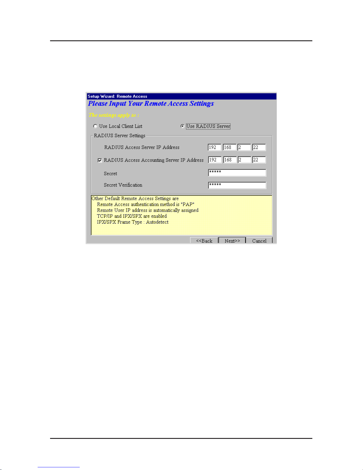
b.)
Use RADIUS Server
Select this option if you would like your remote clients to
be authenticated on a RADIUS server . You must enter the
following RADIUS Server Settings:
•
RADIUS Access Server IP Address:
Enter the IP address
of the RADIUS Access Server.
•
RADIUS Accounting Server IP Address:
Enter the IP
address of the RADIUS Accounting Server.
•
Secret:
Enter your Secret RADIUS code or password.
•
Secret Verification:
To confirm your Secret code, re-enter
your code or password.
Note: In most cases, the RADIUS Access Server and the
RADIUS Accounting Server are the same server, so the IP
address will be the same.
Click Next>> and continue with Step 10.
Page 20
RouteFinder Quick Start Guide
20
2.) IP Routing (NAT Enabled) and
3.) IP Routing (NAT Disabled)
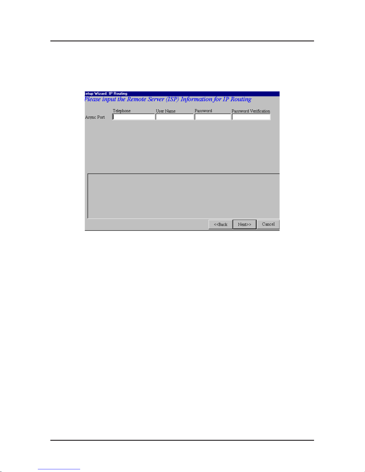
If you select
IP Routing
for the asynchronous port, the
Setup Wizard: IP Routing dialog box displays.
Enter the information required to dial-up and login to your
ISP’s remote server:
•
Telephone Number
: Enter the phone number used to
dial your remote server (ISP).
Note: If you must dial a number to get an outside line
(e.g., “9”, or “0”), enter the required number plus a
“w”(wait) or a comma in the Telephone box. (e.g., 9w5552323 or 9,,5552323) Each comma provides a 3-4 second
delay.
•
User Name:
Enter the User Name for your remote server
or ISP account.
•
Password:
Enter the Password for your remote server or
ISP account.
•
Password Verification:
Re-enter the password for your
remote account.
Click Next>>.
Page 21
Software Installation
21
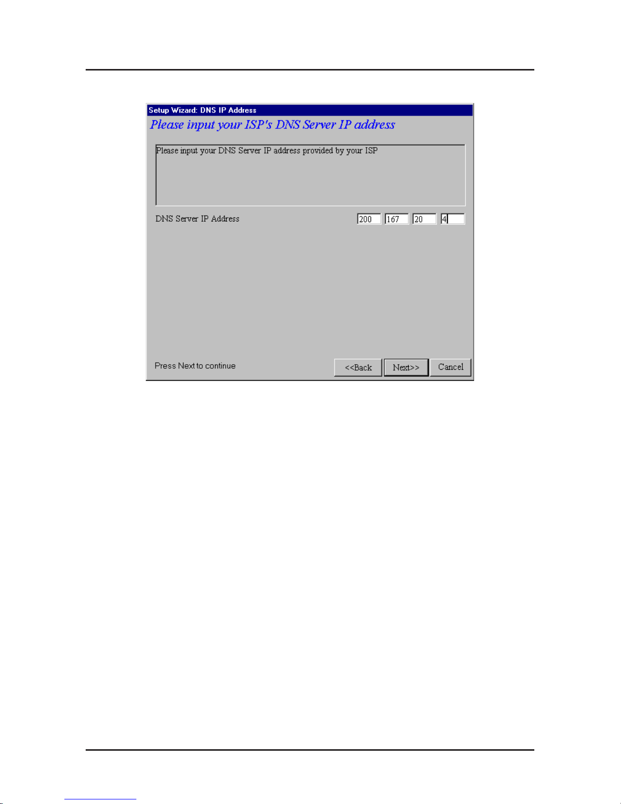
10.The Setup Wizard: DNS IP Address dialog box displays.
Enter your ISP’s DNS Server IP address. If you are not
sure of the IP address, contact your ISP. Refer to the
Glossary in the User Guide for more information about the
DNS Server.
Click Next>>.
Page 22
RouteFinder Quick Start Guide
22
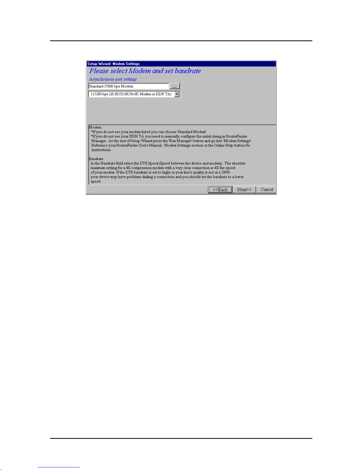
11. The Setup Wizard: Modem Settings dialog box displays.
The final step in configuring your RF500S for basic
operations is to enter the model and DTE baudrate of the
modem you are using. This is an important setting that
determines the DTE baudrate or speed of communication
between the RF500S’s async port and your modem or
ISDN TA.
Select your modem and baudrate as described on the
following pages.
Note: If you do not have a modem or ISDN TA attached to
the RouteFinder async port, use the default modem
values.
Page 23

Software Installation
23
12.To select your modem, in the
Asynchronous port settings
box,
click
The system loads modem information.
Page 24
RouteFinder Quick Start Guide
24
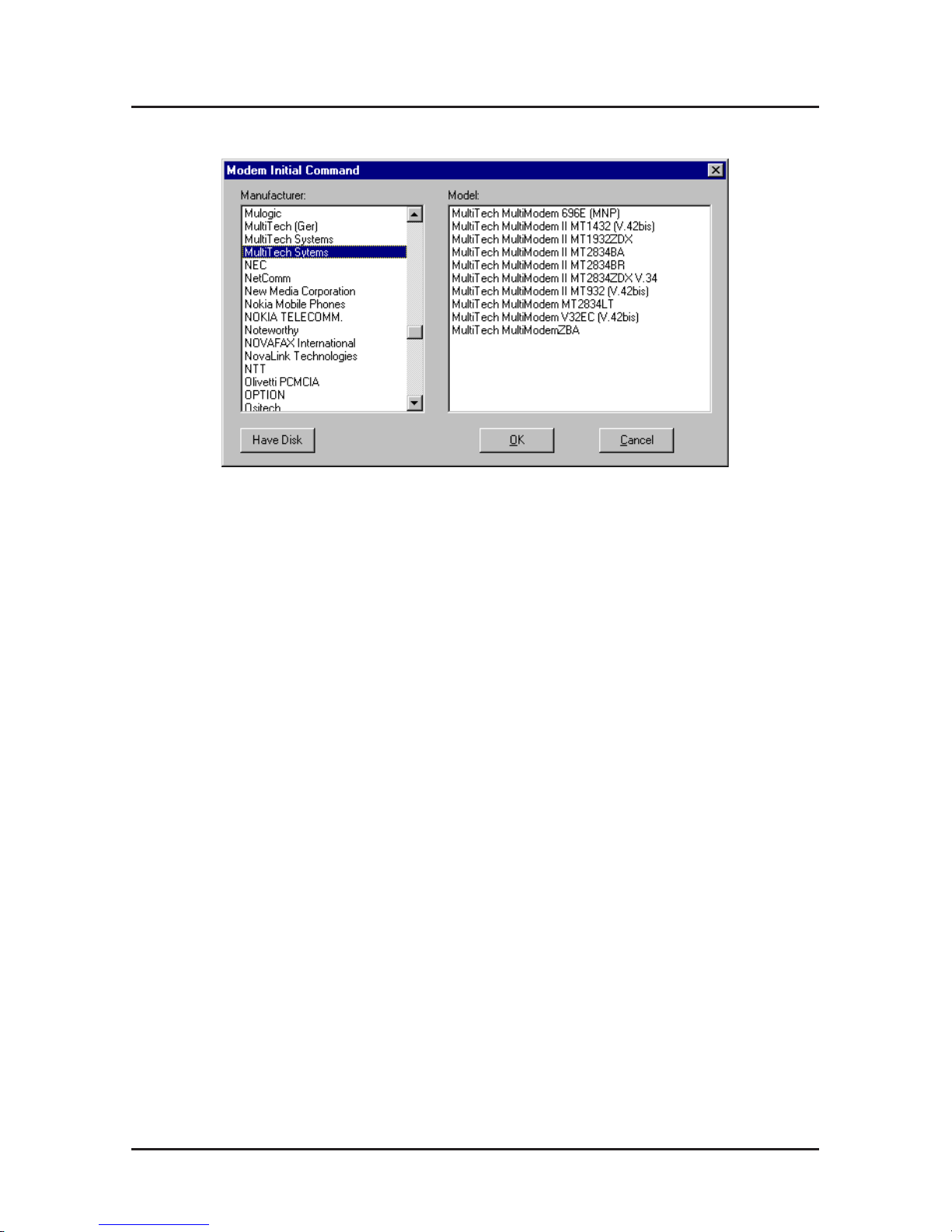
13.The Modem Initial Command dialog box displays.
Select your modem manufacturer and model and click OK.
Note: This setting configures the initial string of the
asynchronous port on the RF500S so that it will know how
to communicate with your modem. If you are using an
analog modem and your modem is not included in the
selection list, in most cases,
Standard Modem
will work. If
you are using an ISDN TA, refer to the ISDN TA’s User
Guide for information on the initialization and hang up
strings. Use RouteFinder Manager to enter your modem
or TA strings.
Page 25

Software Installation
25
14.The Setup Wizard: Modem Setting dialog box re-
displays.
Use the
Asynchronous port settings
list to select the
baudrate. Select the DTE speed (i.e., the speed of
communication between the asynchronous port of the
RF500S and the modem). For DCE speed compression
modems, this value can normally be set to about 4 times
the speed of your modem. Keep in mind that if you set the
baudrate too high, the dial-up connection may fail.
Note: You may need to set a lower baudrate since the
theoretical maximum connection speed may not be
attainable due to variations in quality of phone line and ISP
connection.
Click Next>> to complete the basic configuration.
Page 26
RouteFinder Quick Start Guide
26
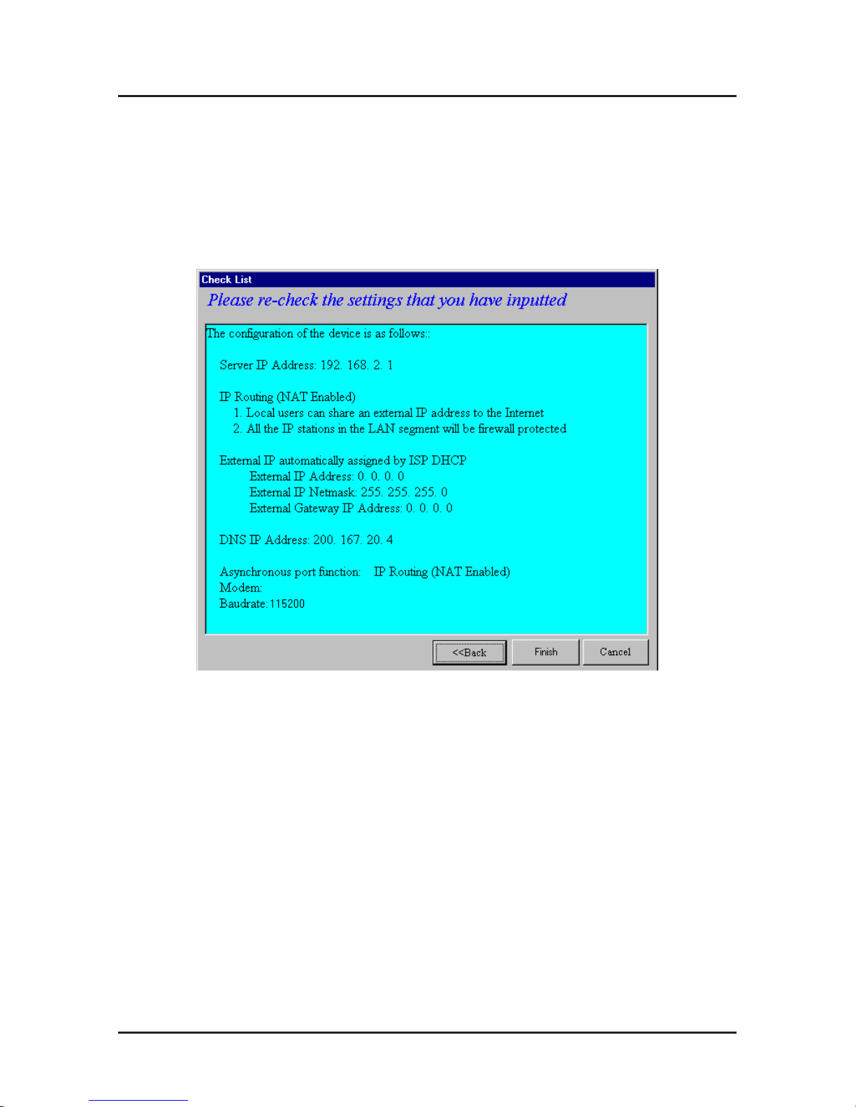
15.The Check List dialog box displays summarizing your
configuration selections. Ensure that all values have been
correctly entered. If you find an incorrect setting, click
<<Back to return to the screen containing the error and
correct it. When complete, use the Next>> button to
return to the Check List dialog box.
Click Finish to complete the configuration.
Page 27
Software Installation
27
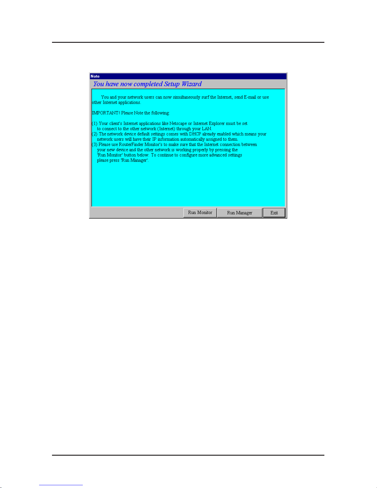
16.The Note dialog box displays indicating that you have
completed the Setup Wizard.
Read the “IMPORTANT!” information contained in the
dialog box. Click Run Monitor (recommended), Run
Manager or Exit.
Page 28

RouteFinder Quick Start Guide
28
Testing your Connection
When you select Run Monitor , the RouteFinder Monitor
program loads.
1. To test your current settings, select Test Connection.
Select Connect Port 1 to test the WAN port. Select
Connect Port 2 to test the async port. The monitor
activity will appear in the display window . Refer to the
RouteFinder Monitor chapter in the User Guide for
additional information about the monitoring capabilities of
the RF500S.
2. Before using the device, you must configure your
workstations for TCP/IP. Refer to the
LAN Client Settings
chapter of the User Guide for configuration information.
Note: If a problem occurs while testing your connection, or
you need to configure advanced options such as filtering,
DHCP or routing, use RouteFinder Manager by selecting
Programs | RouteFinder Manager | RouteFinder
Manager.
Page 29
Software Installation
29
Using Telnet to Configure your RouteFinder
Telnet is a telecommunications software utility which allows
you to access a remote device. The RouteFinder RF500S has
a built-in Telnet Server that enables a Telnet client to remotely
configure the device using a menu system.
Important: Non-Windows operating system users must use
the Telnet menu system to configure the RF500S for
operation.
Note: To successfully configure your RouteFinder using
Telnet, TCP/IP must be correctly configured on your computer
and the router and computer must be located on the
same
subnet.
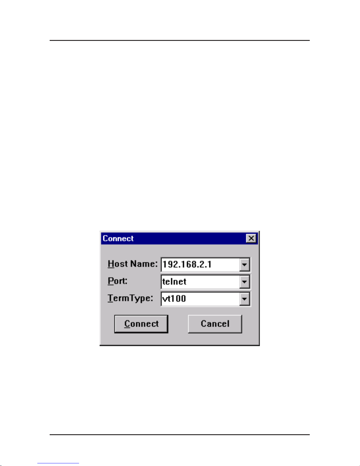
1. Start your telnet session and connect to the RouteFinder
RF500S using the router’s default IP address of
192.168.2.1
and vt100 terminal emulation.
If you are using a graphical interface similar to that shown
above, click Connect.
2. When prompted to input the Router Password, press
Enter.
Page 30
RouteFinder Quick Start Guide
30
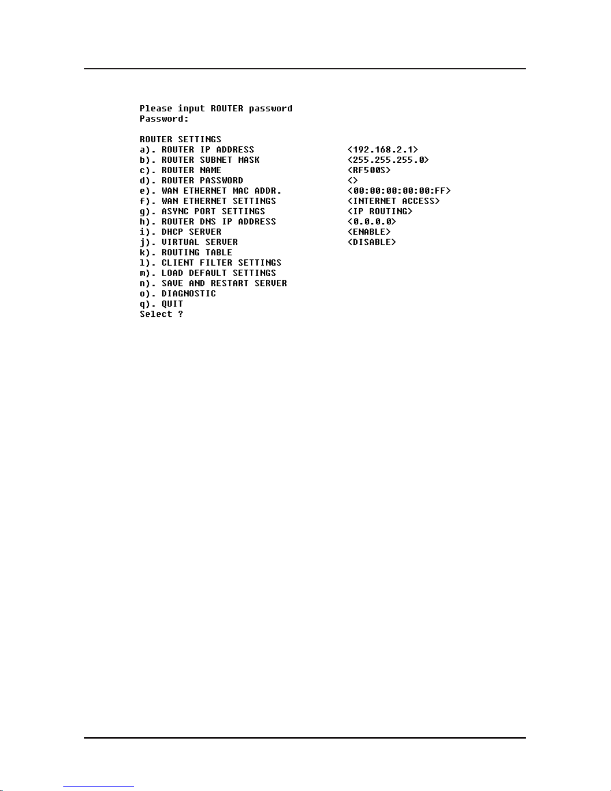
3. The RF500S Telnet Server Menu displays.
To use the menu, select the letter corresponding to the
value you’d like to change.
Depending on the value you are changing, you are
presented with an open field into which you may type new
information, or you are presented with a list of options from
which you may select a value. Refer to the User Guide’s
Telnet chapter for complete descriptions of each option.
Note: After entering values, select “q“ to return to the
previous menu or to quit. You must select Save and
Restart Server to save your configuration to the
RouteFinder’s Flash memory .
Use the following information to configure your RouteFinder:
1. Define the Router IP Address, Router Subnet Mask,
Router Name and Password by selecting the menu letter
corresponding to each item. Enter the values for the
device on your local network in the field provided. The
W AN Ethernet MAC Addr. field displays the hardware
address of the board. You may change the MAC address
if required by your ISP.
2. Select WAN Ethernet Settings to select the function of
the WAN port as
Internet Access
or
LAN -to- LAN Access
.
Page 31

Software Installation
31
Complete the External IP Port Address, External Port IP
Netmask, Gateway IP Address and DNS IP Address
fields using the IP addresses
provided by your ISP
or
remote network administrator
.
3. If you have an analog modem or ISDN TA connected to
the async port, select Async Port Settings and define the
function of the port as
IP Routing
or
Remote Access.
• If you define the async port for
IP Routing:
Enter the Telephone number, User Name and Password
needed to make the connection to your ISP or remote
system. Use the menu options to provide specific
information about your modem’s serial baudrate (speed),
Modem pre-initial, initial, dial-up and hangup strings.
You may also use the menu options to create or edit
Login Scripts as needed. If you are using callback
security, use the menu options to enter the Callback
Telephone number. Enter the IP address of the network
device to which you are connecting in the External IP
Address field. You may Enable NAT to allow all local
LAN users to share one IP address for Internet access
and to provide firewall protection. To assign IP addresses
to remote users, select
Enable
in the Assign Remote IP
field.
• If you define the async port for
Remote Access
, use IP
Assigned Method to define whether or not the remote
users will use the RouteFinder’s DHCP server to obtain
their IP address. Select Protocols and if necessary on
your network, select an IPX/SPX Frame Type. Select the
desired Authentication Method for the dial-in clients.
Use the Edit User Database option to create a list of dialin users. Use the menu options to provide specific
information about your async modem’s serial baudrate
(speed), Modem pre-initial, initial, dial-up and hangup
strings. You may also use the menu options to create or
edit Login Scripts as needed.
Page 32

RouteFinder Quick Start Guide
32
4. In the Router DNS IP Address field, enter the IP address
of your ISP or remote system’s DNS as provided by your
ISP or remote system administrator.
5. Use the DHCP Server option to enable or disable the
DHCP function on the RF500S. If you select enable, you
will be prompted to enter the address range from which
the device will issue IP addresses.
6. Select Virtual Server to define the list of mapped internal
and external IP addresses. For example, you may want to
use IP mapping to access an FTP server on your LAN via
the Internet. Refer to the User Guide for more information.
Note: IP Mapping is available only when NAT is enabled.
7. Select Routing Table and use the menu options to enter
the necessary information to route IP packets from one
network to another . See the User Guide for more
information about Routing.
8. You may define packet filtering options using the Client
Filter Options menu. Refer to the User Guide for more
information on Filtering options.
9. Use Load Default Settings to set the router back to its
original factory settings.
10. Select Apply and Save Changes to save the current
configuration into the RouteFinder’s FLASH memory .
Note: You must select Apply and Save Changes before
leaving the Telnet menu or your configuration changes will
be lost when the RouteFinder is powered off.
11. Select Diagnostic to perform basic hardware checking
and display the RouteFinder’s Firmware Version. You may
also use this option to assign WAN and LAN MAC
addresses if required by your ISP.
12. When all options have been configured
and
after you have
selected Apply and Save Changes, select q.) Quit.
Page 33

Warranty and Service Information
33
Limited Warranty
Multi-T ech Warranty & Repair Policies
Multi-Tech Systems, Inc., (hereafter “MTS”) warrants that its
products will be free from defects in material or workmanship for a
period of two years from date of purchase, or if proof of purchase
is not provided, two years from date of shipment.
MTS MAKES NO OTHER WARRANTY, EXPRESS OR IMPLIED,
AND ALL IMPLIED WARRANTIES OF MERCHANTABILITY AND
FITNESS FOR A PAR TICULAR PURPOSE ARE HEREBY
DISCLAIMED.
This warranty does not apply to any products which have been
damaged by lightning storms, water , or power surges or which
have been neglected, altered, abused, used for a purpose other
than the one for which they were manufactured, repaired by
Customer or any party without MTS’s written authorization, or used
in any manner inconsistent with MTS’s instructions.
MTS’s entire obligation under this warranty shall be limited (at
MTS’s option) to repair or replacement of any products which
prove to be defective within the warranty period or , at MTS’s
option, issuance of a refund of the purchase price. Defective
products must be returned by Customer to MTS’s factory —
transportation prepaid.
MTS WILL NOT BE LIABLE FOR CONSEQUENTIAL DAMAGES,
AND UNDER NO CIRCUMSTANCES WILL ITS LIABILITY
EXCEED THE PRICE FOR DEFECTIVE PRODUCTS.
Service
Multi-Tech has an excellent staff of technical support personnel
available to help you get the most out of your Multi-Tech product.
Refer to your RF500S RouteFinder User Guide for full Warranty
and Service information.
Page 34

82099150
 Loading...