

Page 1

Remote Access Server with
Integrated W AN Devices
Model MTASR3-200
User Guide
Page 2

User Guide
S0000055 Revision E
RASFinder (Model No. MTASR3-200)
This publication may not be reproduced, in whole or in part, without prior expressed written permission from
Multi-Tech Systems, Inc. All rights reserved.
Copyright © 2004-07, by Multi-Tech Systems, Inc.
Multi-Tech Systems, Inc. makes no representations or warranties with respect to the contents hereof and
specifically disclaims any implied warranties of merchantability or fitness for any particular purpose.
Furthermore, Multi-T ech Systems, Inc. reserves the right to revise this publication and to make changes from
time to time in the content hereof without obligation of Multi-Tech Systems, Inc. to notify an y person or
organization of such revisions or changes.
Record of Revisions
Revision Description
A Manual released. All pages at revision A.
(3/23/98)
B Manual revised to include software revision 3.00. All pages at revision B.
(1/26/99)
C Manual revised to include software revision 3.10. All pages at revision C.
(3/19/01)
D Manual updated to remove coax cable connector and include latest softw are.
(4/13/04)
E Manual updated to include a new version of WINMCSI2000 and XP.
(8/02/04)
F Updated the Technical Support contact list and warranty statement and corrected the pin out
(6/20/07) for the command cable. Updated CD image .
Patents
This Product is covered by one or more of the following U.S . Patent Numbers: 5.301.274; 5.309.562;
5.355.365; 5.355.653; 5.452.289; 5.453.986. Other P atents Pending.
TRADEMARK
Multi-Tech and the Multi-Tech logo are registered trademarks of Multi-Tech Systems, Inc. RASFinder is a
trademark of Multi-Tech Systems, Inc.
Adobe Acrobat is a trademark of Adobe Systems Incorporated.
K56flex is a trademark of Rockwell International Corporation and Lucent Technologies Corporation.
Microsoft Windows, Windows 98, 2000, XP and Windows NT are either registered tr ademarks or trademarks
of Microsoft Corporation in the United States and/or other countries.
World Headquarters
Multi-Tech Systems, Inc.
2205 Woodale Drive
Mounds View, MN 55112 U.S.A
Telephone: (763) 785-3500 or (800) 328-9717
Fax 763-785-9874
Internet Address: http://www.multitech.com
Page 3

Contents
Chapter 1 - Introduction and Description.....................................................5
Introduction .......................................................................................................................................................6
Preview of this Guide..................................................................................................................................6
Front P anel........................................................................................................................................................8
Back Panel ..................................................................................................................... ................................... 9
Link Connectors (Links 1, 2, and 3) ............................................................................................................9
Ethernet 10Base-T Connector ....................................................................................................................9
Command Connector..................................................................................................................................9
Power Connector ........................................................................................................................................ 9
Specifications..................................................................................................................................................10
Ethernet Port............................................................................................................................................. 10
Command Port.......................................................................................................................................... 10
WAN Links................................................................................................................................................ 10
Electrical/Physical.....................................................................................................................................10
Requirement ............................................................................................................................................. 10
Chapter 2 - Installation.................................................................................11
Introduction .....................................................................................................................................................12
Unpacking ....................................................................................................................................................... 12
Safety W arning T elecom.................................................................................................................................. 12
Cabling Your RASFinder.................................................................................................................................. 13
Adding RAM ....................................................................................................................................................14
Chapter 3 - Software Loading and Configuration..................................... 15
Installing Y our RASFinder Software ................................................................................................................16
IPX Routing Setup .................................................................................................................................... 19
IP Routing Setup....................................................................................................................................... 19
Setting Up Your Remote User Database ......................................................................................................... 22
Setting Up Remote Access Dial In User Server (RADIUS).............................................................................27
Final Routing Setup ........................................................................................................................................ 29
Chapter 4 - RASFinder Software.................................................................32
Introduction .....................................................................................................................................................33
Before Y ou Begin.............................................................................................................................................33
RASFinder Setup ............................................................................................................................................34
Typical Applications.........................................................................................................................................35
RAS Applications......................................................................................................................................35
Router Application ....................................................................................................................................41
IP Setup ..........................................................................................................................................................44
Filters........................................................................................................................................................49
IPX Setup ........................................................................................................................................................51
Bandwidth Optimization Group .................................................................................................................52
IPX Filters .................................................................................................................................................53
Spanning Tree Setup ....................................................................................................................................... 54
WAN Port Setup ..............................................................................................................................................56
Point-to-Point Setup ........................................................................................................................................57
Applications.....................................................................................................................................................58
Diagnostics .....................................................................................................................................................58
Client ............................................................................................................................................................... 59
iii
Page 4

Chapter 5 - RAS Dial-Out Redirector ..........................................................60
Introduction .....................................................................................................................................................61
Installing and Configuring the WINMCSI Modem-Sharing Software ............................................................... 61
Running the WINMCSI Workstation Software .................................................................................................64
Chapter 6 - Remote Configuration and Management................................67
Introduction .....................................................................................................................................................68
Remote Configuration .....................................................................................................................................68
Modem-Based ..........................................................................................................................................68
LAN-Based ...............................................................................................................................................70
Remote Management......................................................................................................................................72
Telnet ........................................................................................................................................................72
Web Browser Management ......................................................................................................................75
Chapter 7 - Service, Warranty and T ech Support.......................................76
Introduction .....................................................................................................................................................77
Limited Warranty .............................................................................................................................................77
On-line Warranty Registration................................................................................................................... 77
Service ............................................................................................................................................................ 78
U.S. and Canadian Customers.................................................................................................................. 78
International Customers (outside U.S.A. and Canada) .............................................................................78
International Distributors...........................................................................................................................79
Replacement Parts ................................................................................................................................... 79
Technical Support .....................................................................................................................................79
Internet Sites ............................................................................................................................................79
Appendixes...................................................................................................80
Appendix A - Cabling Diagrams ......................................................................................................................81
Appendix B - Script Language ........................................................................................................................82
Appendix C - Regulatory Information ..............................................................................................................84
Class B Statement .................................................................................................................................... 84
Fax Br anding Statement ...........................................................................................................................84
FCC Part 68 Telecom................................................................................................................................85
Ringer Equivalence Number.....................................................................................................................86
EMC, Safety and Terminal Directive Compliance .....................................................................................86
Appendix D - AT Command Summary ............................................................................................................87
Appendix E - TCP/IP ....................................................................................................................................... 94
TCP/IP ......................................................................................................................................................94
Internet Protocol (IP) ................................................................................................................................96
Glossary of Terms ........................................................................................97
Index............................................................................................................111
iv
Page 5

Chapter 1 - Introduction and Description
Page 6
Introduction
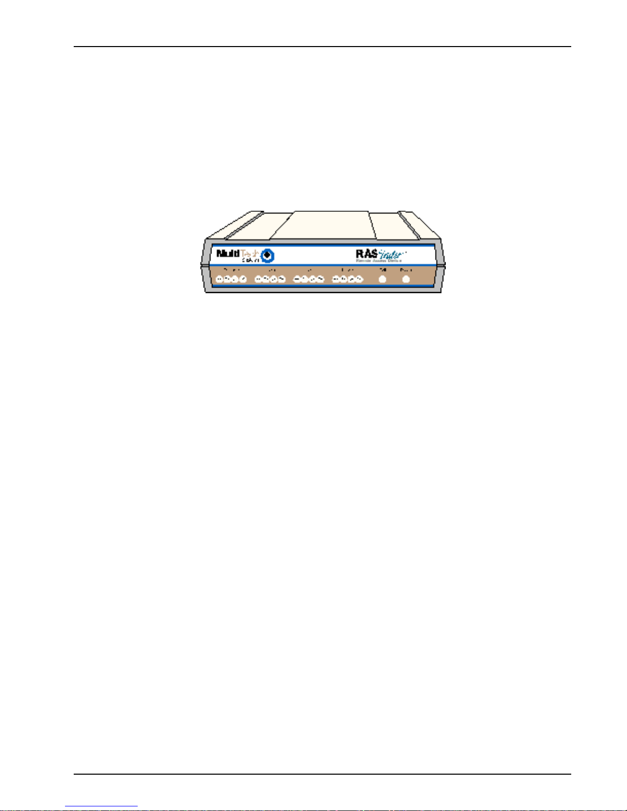
Welcome to Multi-Tech's new RASFinder™ Model MTASR3-200, a Remote Access Server (RAS) for
remote dial-in access and LAN-to-LAN routing capability. The RASFinder 200-Series is a remote
access device that supports up to three concurrent dial-in sessions and IP or IPX remote access.
The RASFinder 200-Series features a 10Base-T port for local LAN connection, Command port for
configuration, and three internal V.90 modems. New features include additional security using MultiTech’s Remote Dial In User Server (Radius), support for Simple Network Time Protocol (SNTP)
clocking, and added security for remote dial-in users. System management is provided through the
Command port using bundled Windows® based software which provides easy-to-use configuration
menus.
Chapter 1 - Introduction and Description
Figure 1-1. RASFinder
Note: Though the modems in the RASFinder are capab le of 56 Kbps do wnload performance, line
impairments, public telephone infrastructure, and other external technological factors currently
prevent maximum 56 Kbps connections.
Preview of this Guide
This guide describes the RASFinder and tells you how to install and configure the unit. The
information contained in each chapter is as follows:
Chapter 1 - Introduction and Description
This chapter describes the RASFinder 200-Series Remote Access Server with integrated WAN
devices. Descriptions of the front panel indicators and back panel connectors and switch are
provided. A list of relevant specifications is provided at the end of the chapter.
Chapter 2 - Installation
This chapter provides information on unpacking and cabling y our RASFinder. The installation
procedure describes each cable connection starting with connecting the power cord, Command port,
LAN and finally the WAN. The software installation process must be done through the MTASR3-200
Command port.
Chapter 3 - Software Loading and Configuration
Chapter 3 details the software loading and initial configuration. Initially, the RASFinder software
configures the unit for a Remote Access Server (RAS) configuration. If you want to configure the
RASFinder for a Lan-to-Lan configuration, you will have to change the Remote Port Setup to a Client
or LAN setting. The RASFinder can also be configured to operate in either a RAS application using a
Radius server for security services or a RAS application using the proprietary Remote User Data
Base Utility for remote user authentication.
MTASR3-200
6
Page 7

Chapter 1 - Introduction and Description
Chapter 4 - RASFinder Software
Chapter 4 describes the RASFinder software designed for the Windows® environment. The software
contains a number of utilities that allow for downloading updated firmware, creating a proprietary
Remote User Data Base, and a terminal emulation utility for configuring the internal modems. Three
typical applications are provided to show you ho w the RASFinder can be configured and some
insight into the application.
Chapter 5 - RAS Dial-Out Redirector
Chapter 5 describes how Multi-Tech’s Remote Access Server for Microsoft network users enables
them to dial out and fax out through the MTASR3-200. It provides information on installing and
configuring the WINMCSI modem-sharing software.
Chapter 6 - Remote Configuration and Management
This chapter provides procedures for changing the configuration of a remote RASFinder located
elsewhere on a LAN or at the other end of a modem connection. This chapter also describes typical
Telnet client and Web-browser management of the RASFinder.
Chapter 7 - Service, Warranty and Tech Support
This chapter provides statements concerning the product warranty, provides space for recording
information about your RASFinder prior to calling Multi-Tech’s Technical Support, and includes
instructions for contacting Technical Support and returning your RASFinder to the factory if it requires
service. Also included is inf ormation on how to obtain product support through the Internet.
MTASR3-200
7
Page 8
Front Panel
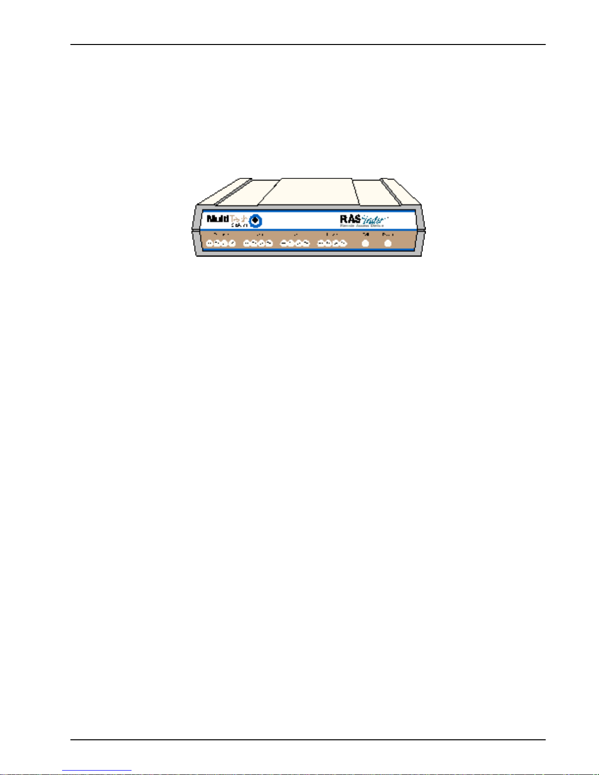
The front panel has four groups of LEDs that provide the status of the LAN connection and link
activity. Two other LEDs indicate the general status of the RASFinder. The Ethernet LEDs display the
activity of the LAN, i.e., whether the RASFinder is connected to the LAN, transmitting or receiving
packets, or if a collision is in progress. The Link LEDs display the status of the three links that can be
connected to the RASFinder and show whether a link is ready to transmit or receive serial data. The
last two LEDs indicate whether the self-test passed or failed and if the pow er ON/OFF switch on the
back of the RASFinder is set to ON.
ETHERNET
Chapter 1 - Introduction and Description
Figure 1-2. Front Panel
RD Receive Data indicator blinks when packets are being received from the local area network.
TD Transmit Data indicator blinks when packets are being transmitted to the local area network.
CL Collision indicator lights when a collision is in progress; that is, when two nodes are
transmitting packets at the same time.
LK Link indicator lights indicating that the RASFinder is connected to the local area network.
LINK x
RD Receive Data indicator blinks when the link is receiving data.
TD Transmit Data indicator blinks when the link is transmitting data.
CD Carrier Detect indicator lights when the link detects a carrier signal.
TR Terminal Ready indicator blinks when the link is ready to transfer data.
Fail Fail indicator lights for 2 minutes when power is applied to the RASFinder; if it remains on for
over 3 minutes , it indicates that a boot failure has occurred.
Power The power indicator lights when the On/Off Switch is in the ON position.
MTASR3-200
8
Page 9
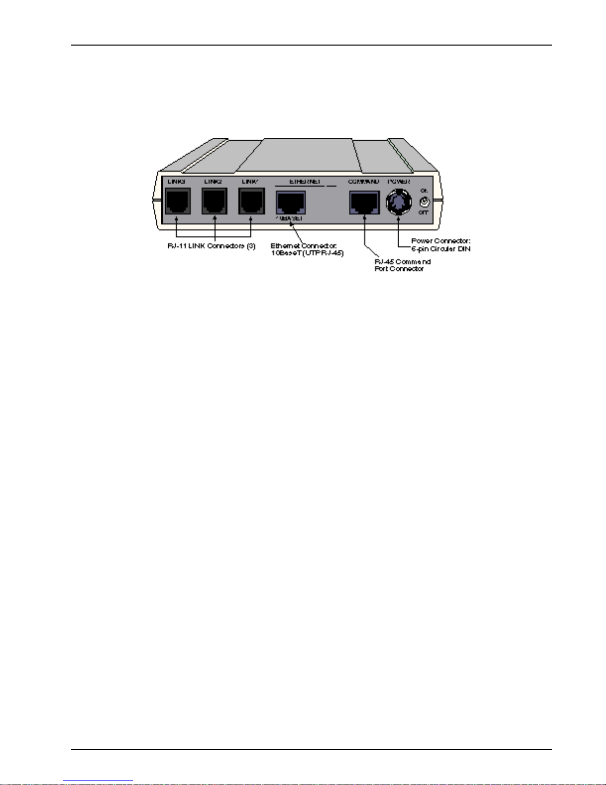
Back Panel
The cable connections for the RASFinder are made on the back panel. Three groups of cables are
used on the RASFinder: the Command port, three RJ-11 ports (Links 1, 2, and 3), and the Ethernet
port. The cable connections are shown in Figure 1-3 and defined in the following g roups.
Chapter 1 - Introduction and Description
Figure 1-3. Back Panel
Link Connectors (Links 1, 2, and 3)
These Link connectors are used to connect the RASFinder to a WAN. These connectors are RJ-11
connectors.
Ethernet 10Base-T Connector
The Ethernet 10Base-T connector is used to connect the RASFinder to a LAN using unshielded
twisted cable. This connector is an RJ-45 jack.
Command Connector
The Command connector is used to configure the RASFinder using a PC with a serial port and
running Windows® software. The Command connector is an RJ-45 jack and a short adapter cable is
provided to convert to a standard serial port DB25 female connector.
Power Connector
The Pow er connector is used to connect the external power supply to the RASFinder. The Power
connector is a 6-pin circular DIN connector. A separate power cord is connected to the power supply
and the live AC g rounded outlet.
MTASR3-200
9
Page 10

Specifications
The RASFinder conforms to the following specifications:
• Routing Protocols - IP and IPX, and bridging for all others
• Ethernet LAN Interface - 10Base-T (twisted pair)
• WAN Interface - 3 async (RS232) Links with RJ-11 jacks
• Command Port - 19.2 Kbps Asynchronous
• Two 70-nanosecond 4 MB SIMMs (8 MB, total)
(RAM is expandable to a maximum of 32 MB)
Caution: SIMM speed and size cannot be mixed.
• 1 MB of Flash memory (on two PROMs)
Ethernet Port
• One Ethernet Interface - 10Base-T (twisted pair) RJ-45 connector.
Command Port
Chapter 1 - Introduction and Description
• Single 19.2 Kbps asynchronous Command Port using a short RJ-45-to-DB9 cable with a
DB9 female connector .
WAN Links
• Three internal V.90 modems* with MultiLink Point-to-Point Protocol for a bandwidth of up to
168 Kbps.
Electrical/Physical
• Voltage - 100 to 250 VAC, 50/60 Hz
• Input Voltage - 5Vdc, 1.4A
• Po w er Consumption - 10 Watts
• Dimensions - 1.625" high x 6" wide x 9" deep
• Weight - 2 pounds (0.92 kg)
Requirement
• PC with Windows 98/2000/XP or Windows NT, and one available serial COM port to connect
to the Command Port of the RASFinder
5.63 cm high x 22.34 cm wide x 33.51 cm deep
* Though this modem is capable of 56 Kbps do wnload performance, line impairments, public
telephone infrastructure and other external technological factors currently prevent maxim um 56
Kbps connections.
MTASR3-200
10
Page 11

Chapter 2 - Installation
Page 12
Introduction
This chapter is organized to provide instructions for unpac king and cabling your RASFinder . The
unpacking section describes the contents of the shipping box and shows how the RASFinder is
packaged. The installation procedure describes each cable connection and shows where that cable is
connected to the RASFinder. If additional RAM is needed on your RASFinder, a detailed procedure is
provided describing how to install a second SIMM.
Unpacking
Chapter 2 - Installation
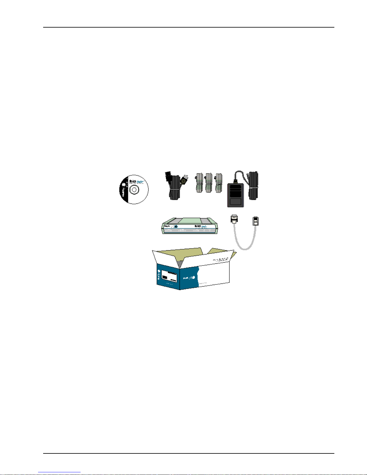
The shipping box contains the RASFinder, external power supply, a plastic bag containing cables,
RASFinder CD with the RASFinder Software, Quick Start, and User Guide in Adobe Acrobat
format. Inspect the contents for signs of any shipping damage. If damage is observed, do not power
up the unit; contact Multi-Tech’ s T echnical Support for advice (refer to Chapter 7). If no damage is
observed, place the RASFinder in its final location and perform the procedures in the section on
“Cabling Your RASFinder. ”
Save the shipping box in case reshipment is necessary.
TM
Safety W arning T elecom
1. Never install telephone wiring during a lightning storm.
2. Never install a telephone jack in wet locations unless the jack is specifically designed for wet
locations.
3. This product is to be used with UL and cUL listed computers.
4. Never touch uninsulated telephone wires or terminals unless the telephone line has been
disconnected at the network interface.
5. Use caution when installing or modifying telephone lines.
6. Avoid using a telephone (other than a cordless type) during an electrical storm. There may be a
remote risk of electrical shock from lightning.
7. Do not use the telephone to report a gas leak in the vicinity of the leak.
8. To reduce the risk of fire, use only 26 AWG or larger telecommunication line cord.
MTASR3-200
Figure 2-1. Unpacking
12
Page 13
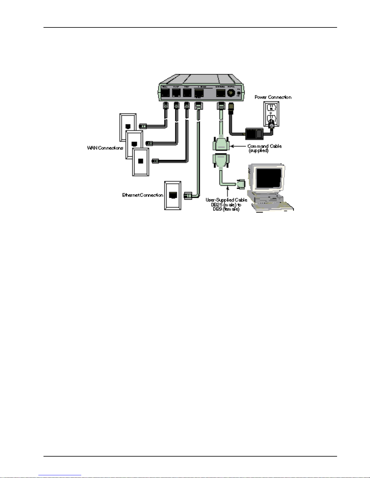
Cabling Y our RASFinder
Cabling your RASFinder inv olves making the proper WAN, Ethernet, Command port, and Power
connections. Should you need to install additional RAM, or replace a SIMM module some time in the
future, refer to the next section on “Adding RAM”.
Chapter 2 - Installation
Figure 2-2. Bac k P anel Connections
Note: If additional RAM is needed, perform the procedure in the next section, “Adding RAM”.
The following steps detail the procedures f or connecting the cables to your RASFinder .
1. Connect the RASFinder to a PC Comm port using the short RJ-45 to DB9 (female) cable
(provided). Plug the RJ-45 end of the Command cable into the Command port of the RASFinder,
then connect the DB9 (female) connector to the PC's serial port. See Figure 2-2.
2. Connect either an RJ-45 (UTP) cable to the 10 BASE-T connector on the back of the RASFinder.
Connect the other end of the cable to your LAN.
3. Connect one end of an RJ-11 cable to each of the LINK Connectors on the RASFinder (labeled
LINK 1, LINK 2, and LINK 3) and connect the other end to the phone jacks (shown in Figure 2-2).
4. Connect one end of the power supply to a live A C outlet, then connect the other end to the
RASFinder as shown in Figure 2-2. The pow er connector is a 6-pin circular DIN connector.
5. Turn on power to the RASFinder by setting the ON/OFF switch on the back panel to the ON
position.
At this time your RASFinder is completely cabled.
Proceed to the next section to install the RASFinder software.
MTASR3-200
13
Page 14
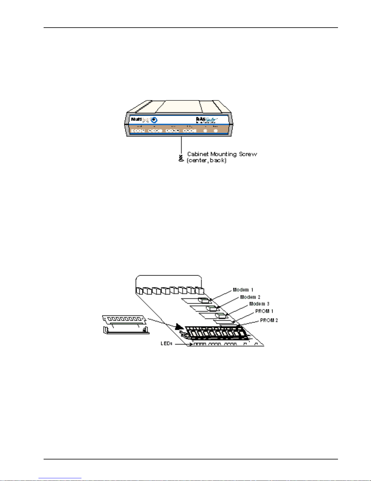
Adding RAM
A second SIMM connector is provided for adding RAM to the RASFinder. The procedure for adding
RAM follows.
1 . Ensure that the external power supply is disconnected from the RASFinder.
2 . Turn the RASFinder upside down and remo ve the cabinet mounting screw at the center/back of
the cabinet.
3. Turn the RASFinder right side up, then slide the base out the rear of the cabinet.
4. Position the base so the front panel LEDs are toward you (as in Figure 2-4).
Chapter 2 - Installation
Figure 2-3. Cabinet Mounting Screw
Note: As long as both SIMMs are identical in type, size, and speed, the RAM in this unit can be
expanded from 8 MB to 16 MB, or 32 MB , total.
5. Slant the SIMM at a 45o angle to the back of the base and align the centering notch of the SIMM
with the center tab on the SIMM connector.
6 . Gently press down on the ends of the SIMM until the two short vertical white pins enter the holes
at the ends of the SIMM and the two metal side clips snap in place over the SIMM, locking it
down.
Figure 2-4. Installing a SIMM
7 . Align the base with the mating guides on the inside of the cabinet, then slide the base all the way
into the cabinet until it stops.
8 . Turn the RASFinder upside down and replace the cabinet mounting screw that was removed in
step 2.
9 . Turn the RASFinder right side up and return to the previous section, Cabling Your RASFinder to
connect the cables.
MTASR3-200
14
Page 15

Chapter 3 - Software Loading and Configuration
Page 16
Chapter 3 - Software Loading and Configuration
Installing Your RASFinder Software
The RASFinder software is set up to default to a Remote Access Server (RAS) application. Within
the RAS application, you can configure the RASFinder to communicate with a Radius Server for
centralized network security or a proprietary Remote User Data base utility to establish your remote
user profiles. You can also configure the RASFinder as a router for LAN-to-LAN routing.
The RASFinder CD-ROM contains your RASFinder software , Quick Start and this User Guide. The
CD-ROM is auto-detectable and should start automatically when inserted into your CD-ROM drive.
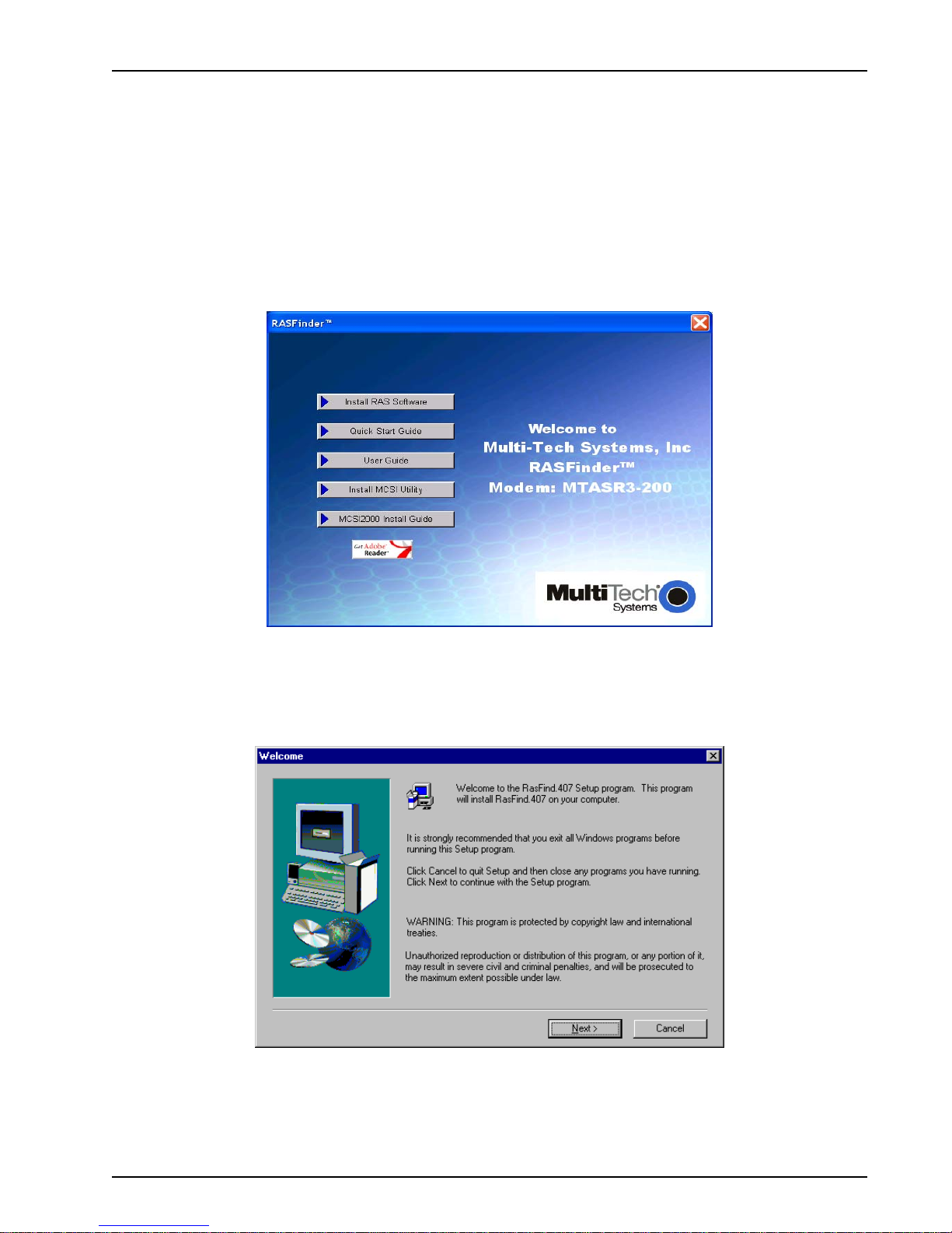
1. Insert the RASFinder CD-ROM into the CD-ROM drive on your local PC. The CD-ROM should
start automatically; however, it ma y take 10 to 20 seconds for the RASFinder screen to appear.
If the RASFinder Splash screen does not appear automatically, click My Computer, right-click
the CD-ROM drive icon, then click Autorun .
2. When the RASFinder screen appears, click the Install RAS Software button.
3. The welcome screen displays.
Press Enter or click Next to continue.
MTASR3-200
16
Page 17
Chapter 3 - Software Loading and Configuration
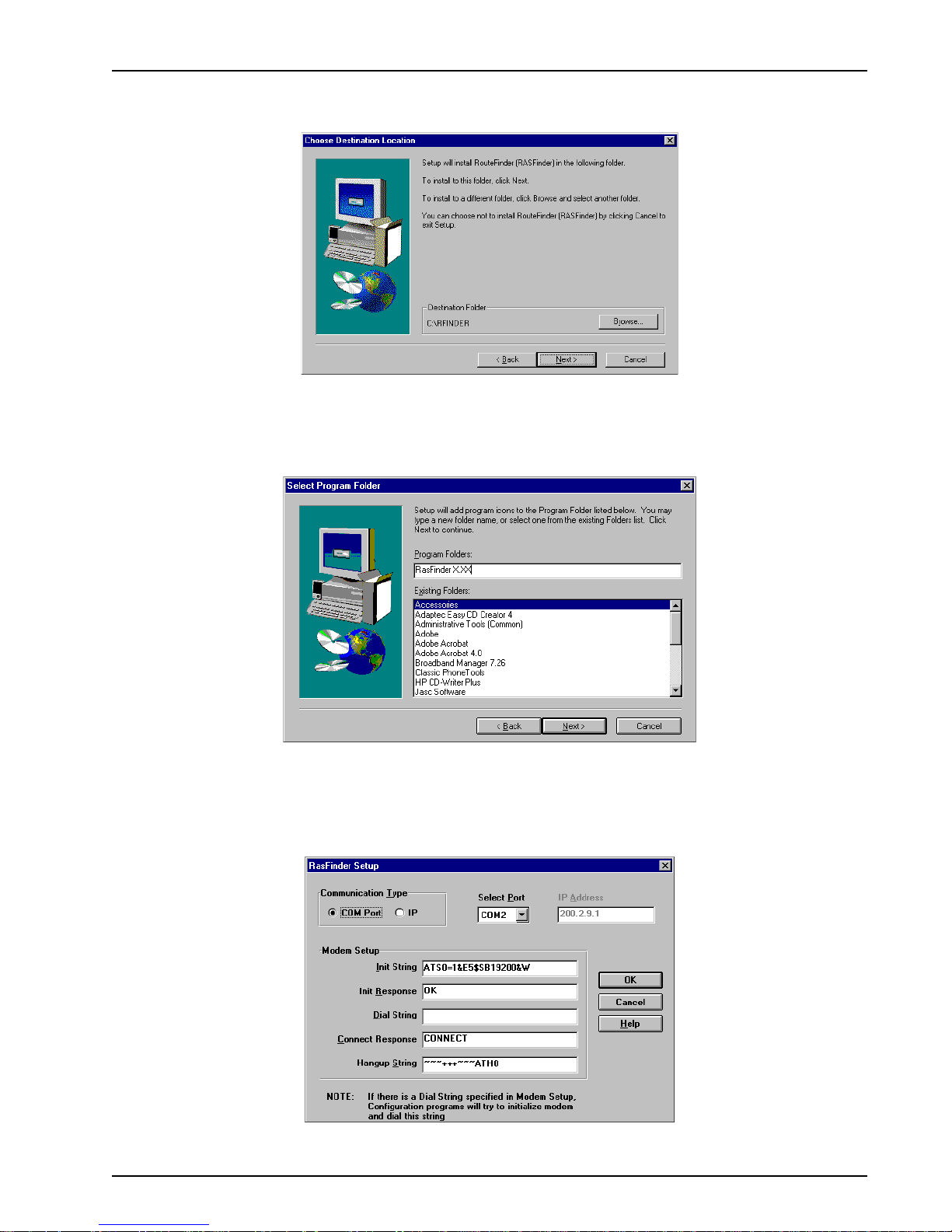
4. The Choose Destination Location dialog box displays . Follow the onscreen instructions to
install your RASFinder software.
You can either choose a different Destination Location for your RASFinder software by clicking
Browse, or select the default destination by pressing Enter or clicking Next>. It is recommended
that you accept the default f older, C:\RASFind.xxx
5. The Select Program Folder dialog box appears.
Press Enter or click Next> to continue
6. The software is loaded onto your PC. The RASFinder Setup dialog box is then displa yed
enabling you to designate the COM port of the PC that is cabled to the RASFinder. From the
Select Port drop-down box, click the down arrow and select the COM port of your PC (COM1 -COM4) that is cabled to the RASFinder .
Click OK to continue.
MTASR3-200
17
Page 18
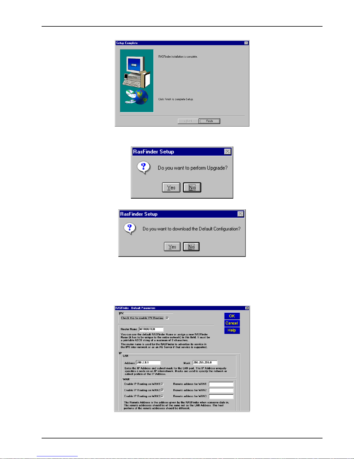
7. The Setup Complete dialog box displa ys .
Click Finish to continue.
8. The following message displays:
Chapter 3 - Software Loading and Configuration
9. Click No to skip the upgrade process . The following message appears:
10. Click Yes to download the default setup . (Clicking No prevents y ou from setting up the defaults
and downloading them to the RASFinder; instead, you are returned to the desktop , where y ou
will see a window with shortcut icons for the various utility programs in the softw are.)
11. The Default Parameters dialog box displays. This dialog box allows you to enable or disable IPX
routing, assign the router name (required for IPX routing), establish the IP address and mask f or
the LAN port, set up remote addresses for the W AN ports, and disable un used WAN ports.
12. If your network protocol is IPX, continue with the follo wing step. However, if your network protocol
is IP, click the IPX Routing Enable chec k box to
MTASR3-200
disable
IPX, then proceed to step 14.
18
Page 19
IPX Routing Setup
13. Router Name: If this is the only RASFinder on your network, you can use the default Router
Name (MTROUTER); otherwise, you must assign a new Router Name in this field. The Router
Name can be any printable ASCII string of up to 8 characters (can be mixed uppercase and
lowercase). The RASFinder will use this name to advertise its service in the IPX internetwork or
as an AG Server , if that service is supported. Proceed to step 15.
Chapter 3 - Software Loading and Configuration
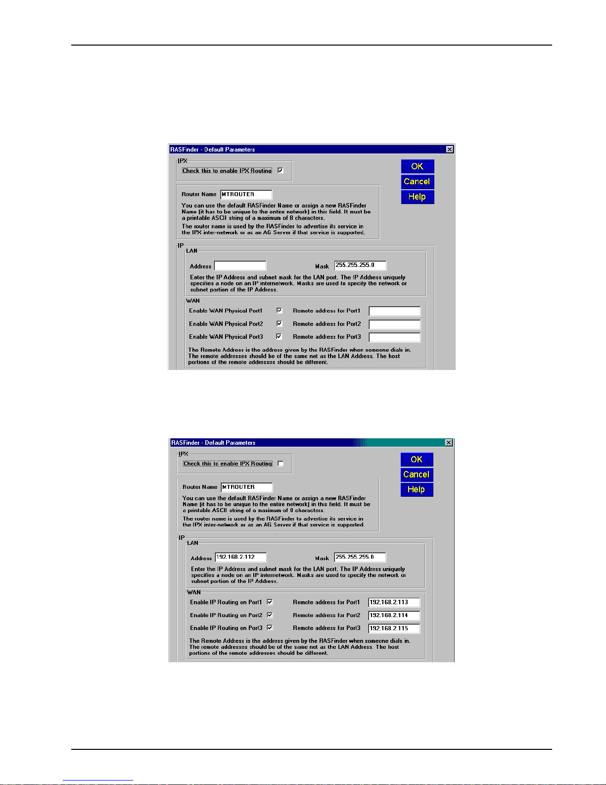
IP Routing Setup
14. For IP Routing, the default Ethernet IP Address has to be changed to your unique LAN address,
and the WAN Remote Addresses have to be in the same network as the LAN Address.
In the IP group, change the def ault Ethernet Ad dress to the value assigned to your RASFinder’ s
LAN port. As you click OK, sequential addresses will appear in the Remote address fields for
WAN1, 2, and 3. (See above, where the Ethernet IP Address was entered as 192.168.2.112, and
the software applied the next three sequential addresses (192.168.2.113,114, and 115) to WAN1,
WAN2, and WAN3, respectively.)
MTASR3-200
19
Page 20
Chapter 3 - Software Loading and Configuration
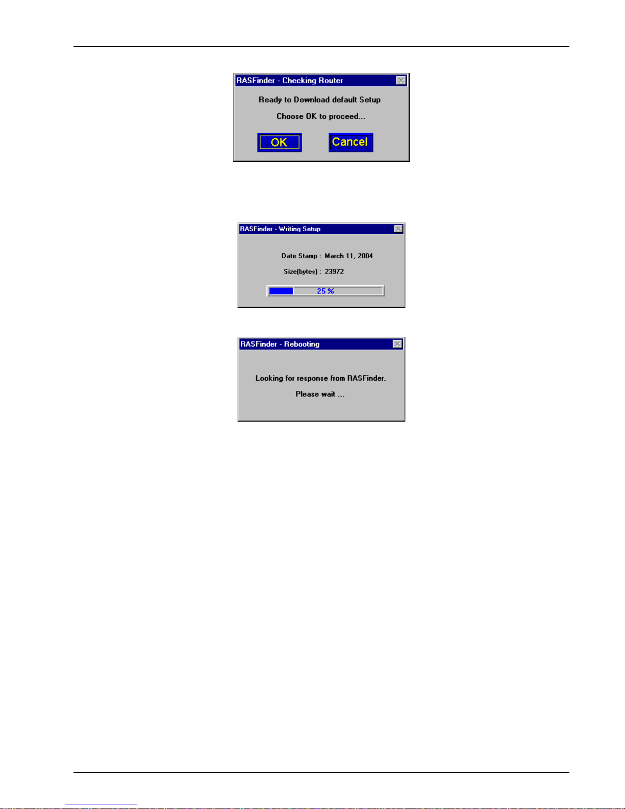
15. The following message displays.
Click OK to proceed.
16. The Writing Setup dialog box (with the current date and the file size in bytes) displa ys as the
setup configuration is written to the RASFinder.
17. Next, the Rebooting dialog box displays.
18. Check to ensure that the Fail LED on the RASFinder goes Off after the download is complete
and the RASFinder is rebooted (the Rebooting dialog box goes a way). This may take several
minutes as the RASFinder reboots.
19. If you are going to establish your remote user profile database using the proprietary Remote
User Database utility, proceed to the next section, or if you are going to use a Radius server for
centralized network security, proceed to the section entitled, Setting Up Remote Access Dial In
User Server (RADIUS).
For Routing, proceed to the last section (Final Routing Setup) in this chapter to set up the
RASFinder as a router.
MTASR3-200
20
Page 21
Chapter 3 - Software Loading and Configuration
Setting Up Your Remote User Database
The propreitary Remote User Data Base supports remote dial-in users for user name, pass w ord, and
port availability. Each dial-in user needs an entry in this database. You can add remote users, remove
users, or edit information in the database.
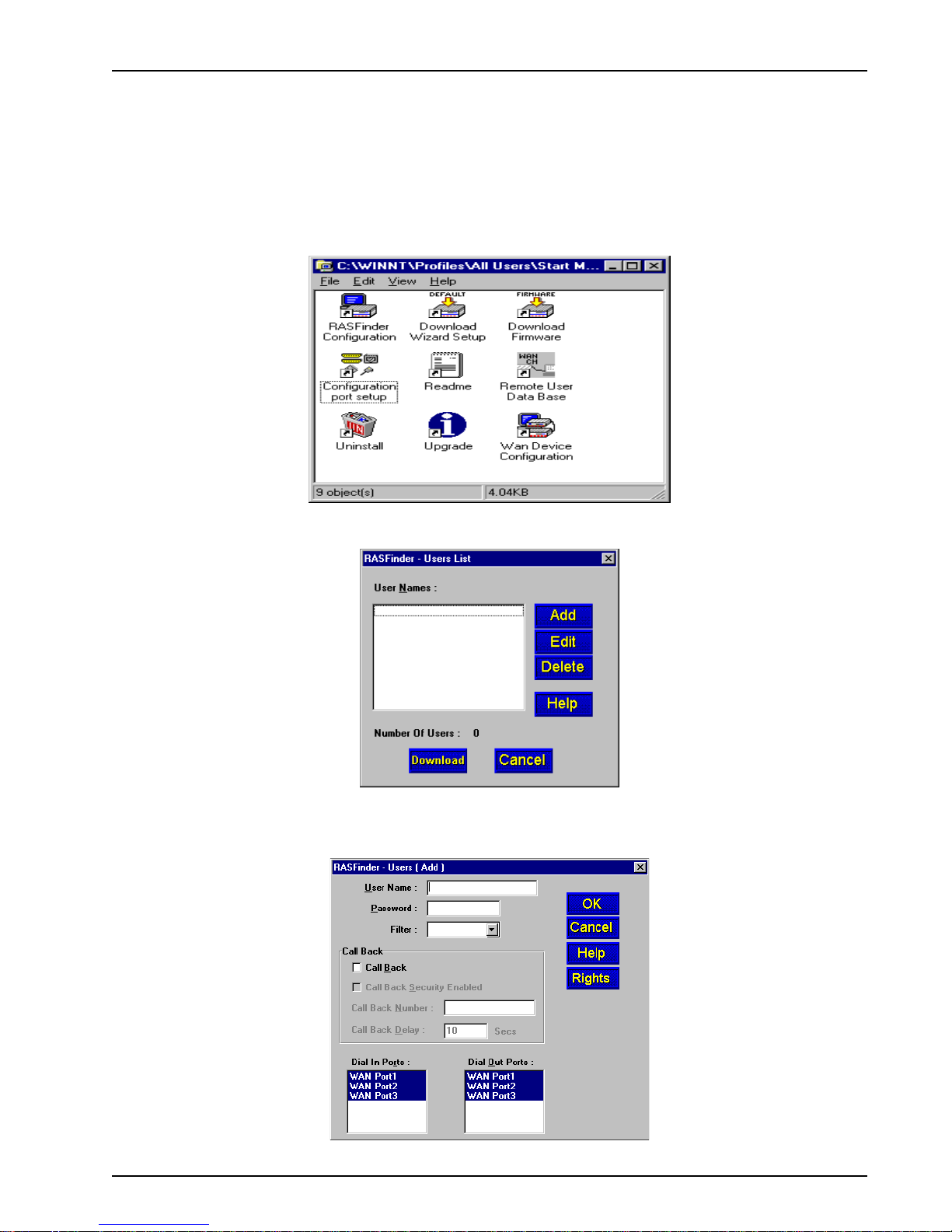
1. From y our desktop, click Start | Programs | RASFinder x.xx | Remote User Data Base, or
double-click the Remote User Data Base icon in the RASFinder x.xx icon group window
(below).
2. An Accounting Info - Read screen appears briefly, then the Users List dialog box displays.
Click Add.
3. The Add Users dialog box displays.
MTASR3-200
21
Page 22

Chapter 3 - Software Loading and Configuration
4. Build your user database by filling in the following fields for each user.
User Name
The User Name can have as many as 39 characters. All printable characters are permitted with
the restriction that no blanks are allowed in the user name. In dial-in and dial-out applications, the
user name is treated as a case insensitive string.
User Passwor d
The User Password can have as many as 7 characters. In places where the password is used as
a character string, it is treated as a case insensitive string. Elsewhere (PPPs CHAP), it is treated
as a case sensitive pattern.
Filter
The drop-down list enables you to select the unique filter entry that was defined in the ID field in
the Add/Edit Filters dialog box. This filter ID must be a unique alphanumeric identifier of up to 9
characters in length that identifies the remote user.
Call Back
You have to click this check box to enable the Call Back function. If the user is at a location where
he wants to be called at then he must be allowed to choose the specific location where he wants
to be called back at. To do this, the Call Back option must be enabled (activated) and the Call
Back Security Enabled option must NOT be enab led (activated). The remote user would then use
a standard PPP client or ASCII terminal dial-in.
To enable Call Back Security , the Call Back option must be checked (activated) and the following
three boxes/fields filled in.
• Call Back Security Enabled
This parameter is of use in dial-in applications where the user must always be called back at
a specific location. Enabling this parameter (Alt-S) results in having the administrator
assigning the call back parameters. Leave this function disabled if the user is to be allowed to
choose the call back number and the call back delay.
• Call Back Number
The Call Back Number is editable only if Call Back Security is enabled (checked). This is the
number where the user will be called back. The user cannot choose the location where he
wants to be called back.
Note: You can enter the Call Back Number with or without dashes, the modem will simply
ignore them.
• Call Back Delay
Call Back Delay is editable only if Call Back Security is enabled. This specifies the duration
(in seconds) after which the user will be called back at the administrator-assigned number.
Dial In Ports
The systems administrator can enable (highlight) WAN Ports 1, 2, and/or 3 to be made available
for dialing in to the RASFinder.
Dial Out Ports
The systems administrator can enable (highlight) WAN Ports 1, 2, and/or 3 to be made available
for dialing out from the RASFinder .
Click the Rights button to assign user permissions for the remote user.
MTASR3-200
22
Page 23
Chapter 3 - Software Loading and Configuration
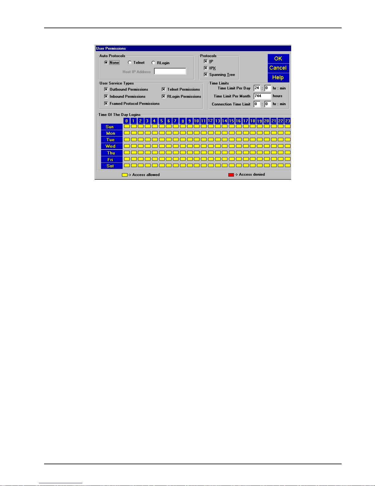
5. The User Permissions dialog bo x displays.
6. Build your user permissions by filling in the following fields for each remote user.
Auto Protocols
This group enables the systems administrator to assign unrestricted LAN/Intranet access or
limited protocol access. You have the follo wing three options.
• None
This option allows the user to have unrestricted access to the LAN/Intranet. This is the
default setting.
• Telnet
This option allows Telnet sessions between the designated server (defined by the Host IP
Address field) and the remote users. Telnet is an applications-level protocol commonly found
in IP-based networks that allow terminal emulation at a remote workstation. If you select
Telnet, you are required to enter an IP address in the Host IP Address field. This limits the
user to only specific functions on the network.
• RLogin
This option allows the RASFinder to be used as an RLogin client for connecting to an RLogin
Server (defined by the Host IP Address field). RLogin is an application protocol that provides
a terminal interface between Unix hosts using TCP/IP network protocol. Unlike Telnet, RLogin
assumes that the remote host is a Unix machine. If you select RLogin, you are required to
enter an IP address in the Host IP Address field. This limits the user to only specific functions
on the network.
Host IP Address
Enter the IP Address for the Telnet or RLogin host computer (server). The Host IP Address must
be in dotted-decimal notation format.
Note: This field is only enabled (activated) when either Telnet or RLogin ha ve been enabled.
MTASR3-200
23
Page 24
Chapter 3 - Software Loading and Configuration
Protocols
The Protocols group enables you to limit the remote user to IP routing, IPX routing, or bridging
(Spanning Tree); or, a combination of any two or all three routing protocols. The default setting
enables all three protocols.
User Service Types
The User Service Types group enables you to set the permissions for the entry being configured.
The systems administrator can enable or disable the following options to customize the types of
services for a particular remote user. By default, all permissions are enabled. To deny
permissions to the entry being configured, click (check) the box to the left of the permission to
disable the feature.
• Outbound Permissions - grants the remote user dial-out rights.
• Inbound Permissions - grants the remote user dial-in rights.
• Framed Protocol Permissions - gr ants the remote user fr amed protocol rights (e.g.,
Framed Protocol – PPP). By enabling (checking) this option, the user becomes an
unrestricted user (i.e., both framed and unframed protocols are allowed).
• Telnet Permissions - grants the remote user Telnet file transfer rights.
• RLogin Permissions - grants the remote user RLogin server connection rights.
Time Limits
The Time Limits group enab les the systems administrator to impose time-related restrictions to
the entry being defined.
Note: The SNTP Client check box must be selected in the SNTP Setup dialog box and pointed
to a valid time protocol server in order to monitor Time Limits and Time of the Day Logins.
Time of the Day Logins
The User Permission grid enables the administrator to deny a remote user Internet access at
certain times during the week. This would be applicable when the administrator wants to bring a
system down for a particular reason and does not want users to access the Internet at that time.
By default, all time periods are color-filled with yellow indicating that the remote user has
permission to access the Internet all the time. To deny permission for certain periods of time,
click all applicable yello w boxes over the target time range to toggle them to red (Access
Denied).
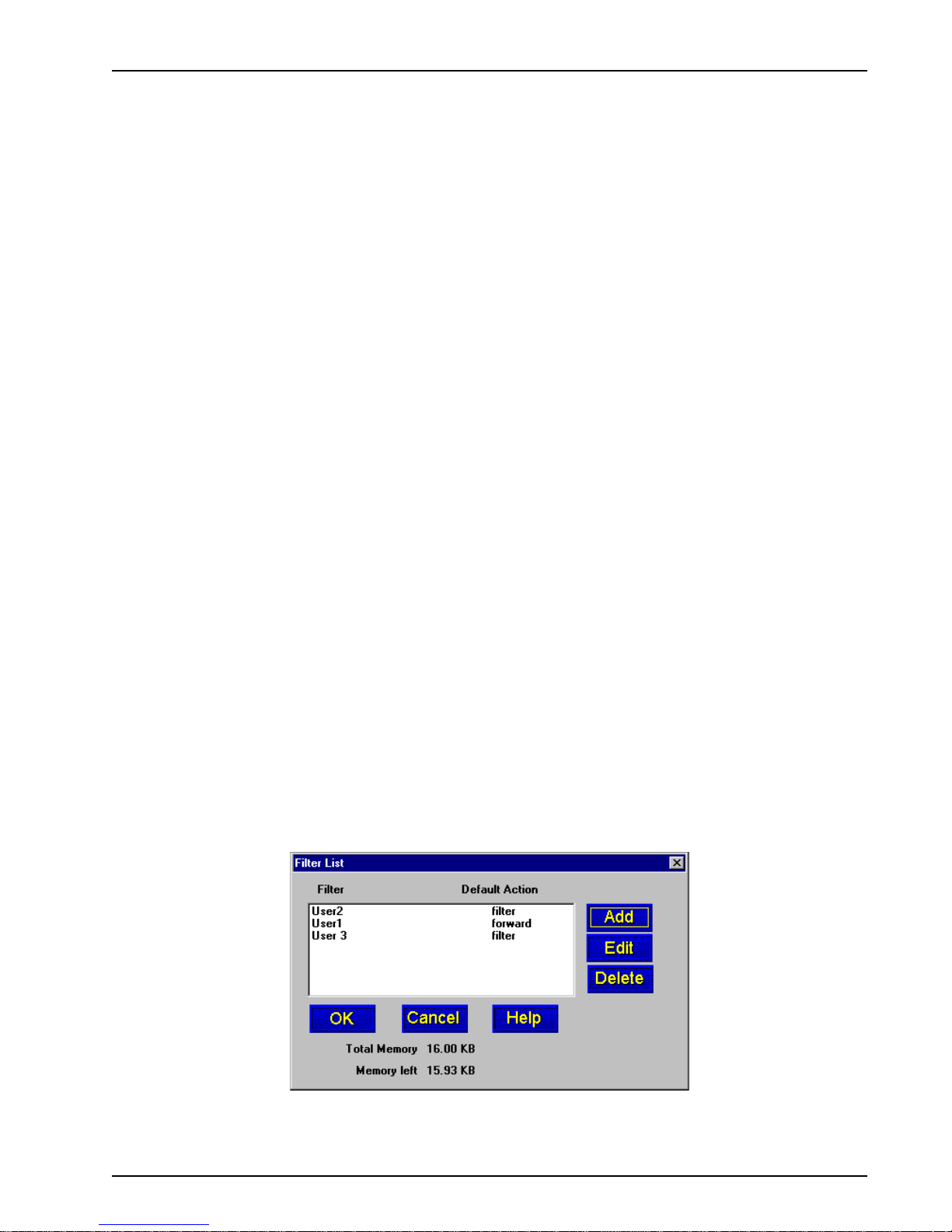
7. After each user is defined in the Add Users dialog box and the user permissions (Rights) have
been configured, click OK to display the updated Users List dialog bo x. Click Filters to add
filtering parameters for the remote user entry.
8. The Filters List dialog box displa ys.
Click Add.
MTASR3-200
24
Page 25
Chapter 3 - Software Loading and Configuration
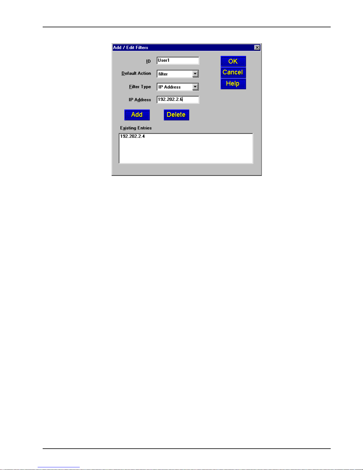
9. The Add/Edit Filters dialog box displays.
10. Build your filtering parameters by filling in the following fields for each remote user.
ID
This field requires a unique ID identifying the remote user. The ID can be the name of a
person, a work station, or a remote user identified simply as “User 1”. The ID can be up to 9
alphanumeric characters in length.
Default Action
This drop-down list enables you to select either filter or forward. If you select filter , then the
entry will be transmitted with filtering properties. If you select forward, then the entry will be
transmitted without filtering properties. The default setting is filter.
Filter Type
The Filter Type drop-down list enables you to select the filter type. The filter types are either
IP Address, Protocol, or Domain Name. The default setting for Filter Type is IP Address.
• IP Address – If the filter type is IP Address, enter the IP Address of the remote user
in dotted-decimal notation format.
• Protocol – If you select Protocol as the filter type, the Ad d/Edit Filter s dialog box is
displayed with Protocol and Port drop-down list fields. Select either TCP or UDP from
the Protocol drop-down list and select either Telnet, FTP, or SFTP from the Port
drop-down list.
• Domain Name – If you select Domain Name as the filter type, the Add/Edit Filters
dialog box displays with a Domain Name field. Eenter the domain name
consisting of a sequence of names separated by periods (dots) follow ed by an
extension, e.g., “pictures. computers .com.” The domain name can be up to 39
alphanumeric characters including periods.
Note: Current filter entries are displayed in the Exisiting Entries window.
Click OK to add the remote user to the Filters List dialog box and then click OK again to return
to the Users List dialog box.
11. Click Add User to continue adding users to your database.
12. When you have added all users to the database, click Download to write the database to the
RASFinder.
MTASR3-200
25
Page 26
Chapter 3 - Software Loading and Configuration
Setting Up Remote Access Dial In User Server (RADIUS)
RADIUS is an optional security feature that uses a single authentication server to centralize security
on networks with large modem pools, especially those with multiple communication servers.
1. From y our desktop, click Start | Programs | RASFinder x.xx | RASFinder Configuration, or
double-click the RASFinder Configuration icon in the RASFinder x.xx icon group window
when it displays on your desktop.
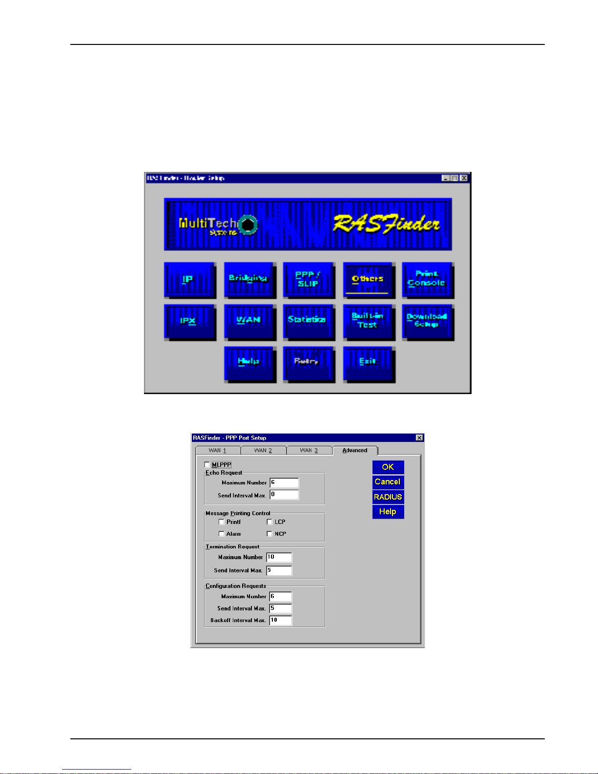
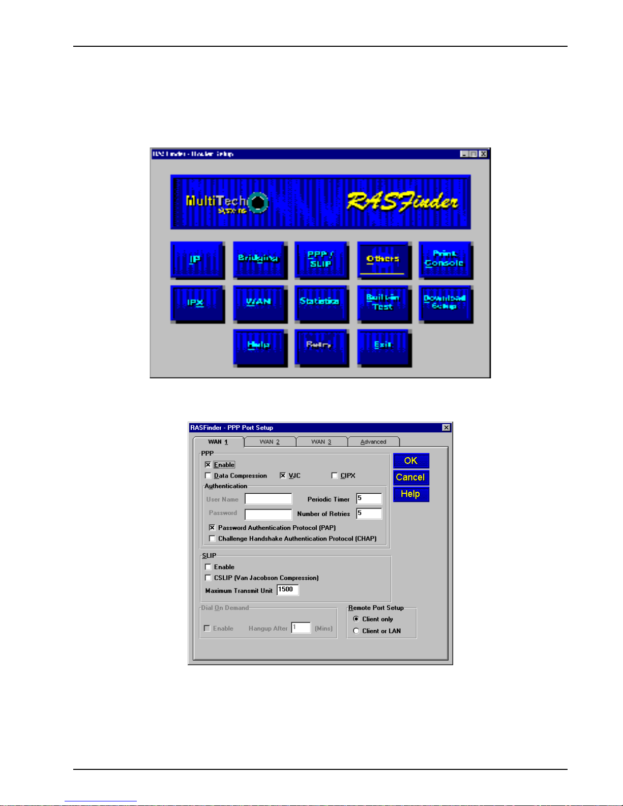
2. The main menu (Router Setup) displays.
Click PPP / SLIP to continue.
3. The PPP Port Setup dialog box displays; click the Advanced tab.
Click RADIUS to continue.
MTASR3-200
26
Page 27
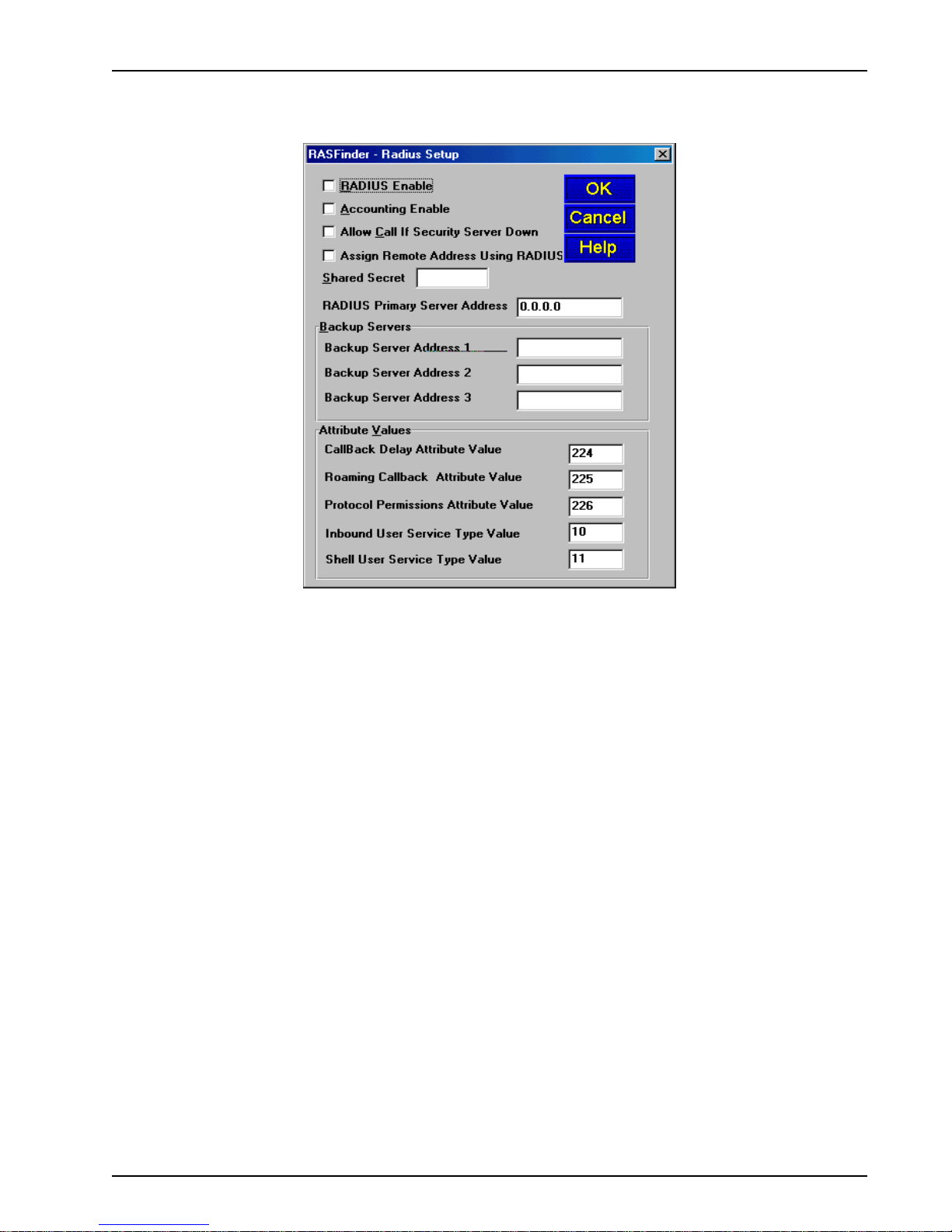
4. The Radius Setup dialog box displays .
Chapter 3 - Software Loading and Configuration
5. Click RADIUS Enable to enable Radius security services for all ports on this RASFinder.
6. Click Accounting Enable if y ou want Radius to track accounting information such as login and
logout times, bytes sent and received, etc.
7. Leave Allow Call if Security Server Down unchecked (disab led) to prevent users from logging
in if the security servers are down.
8. Click Assign Remote Address Using RADIUS to enable the Radius Server to automatically
assign the IP Address of the WAN port on the RASFinder that the user will dial into.
9. Obtain the Shared Secret from the Radius network administrator. The Shared Secret must be
the same secret that is used on the Radius server whose address is being supplied for the
Radius primary server address entry.
10. Obtain the Radius server address from the Radius network administrator that will provide the
security to the RASFinder. The Radius server address is to be enterred in the RADIUS Primary
Server Address field.
11. If additional servers are being used as backup servers, obtain their address(es) from the Radius
network administrator and enter them in Backup Servers group. The first backup server address
is enterred in the Backup Server Address 1 field. Any additional backup server addresses are
to be enterred in the Backup Server Address 2 and Backup Server Address 3 fields.
12. A set of default attribute values will be displayed in the Attribute V alues group. These default
values are used with the Multi-Tech Radius Server. You do not have to change these values if
your RASFinder is communicating with Multi-Tech’s Radius Server. If you are using another
vendor’s Radius Server to communicate with your RASFinder, you will have to communicate with
your Radius Server network administrator to see how he/she has set up these attribute values
and then change the default values to the values being used by that Radius server.
MTASR3-200
27
Page 28
Final Routing Setup
1. From y our desktop, click Start | Programs | RASFinder x.xx | RASFinder Configuration, or
double-click the RASFinder Configuration icon in the RASFinder x.xx icon group window when
it displays on your desktop.
2. The main menu (Router Setup) displays.
Chapter 3 - Software Loading and Configuration
Click PPP/SLIP button to continue .
3. The PPP Port Setup dialog box displays.
On the W AN 1 tab, click Client or LAN in the Remote P ort Setup group in the bottom right
corner; this enables Client or LAN and disables the default, Client onl y. Repeat this on the
WAN 2 and WAN 3 tabs in turn.
MTASR3-200
28
Page 29
Chapter 3 - Software Loading and Configuration
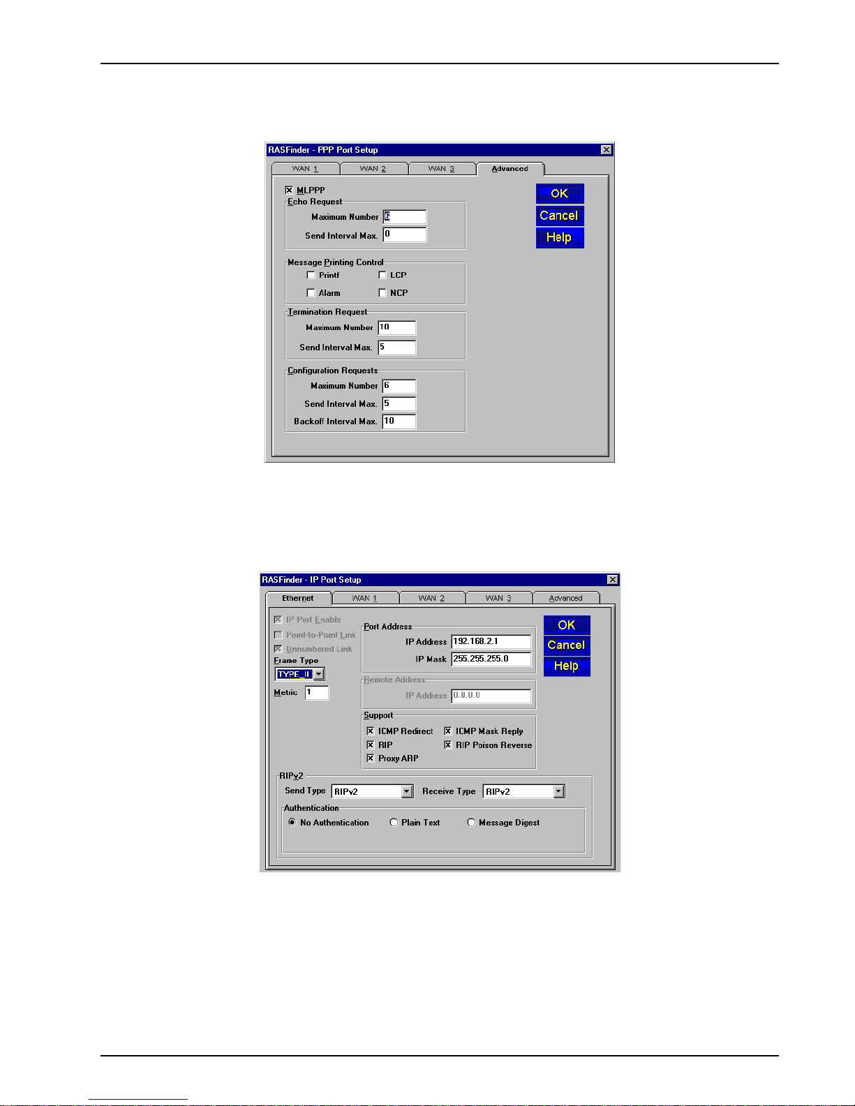
4. If you are going to combine the three WAN ports together, i.e., a single IP address, you need to
enable the MLPPP option from the Advanced tab.
Note: When the dialog box “When a PPP port is Client-or-LAN type:” appears, click on the
OK button each time the dialog box appears. You are returned to the Main menu.
5. From the Main menu, click on the IP button and the IP Port Setup dialog box appears with the
Ethernet tab active and the Port Address displaying y our LAN IP Address.
Click on the W AN 1 tab
MTASR3-200
29
Page 30
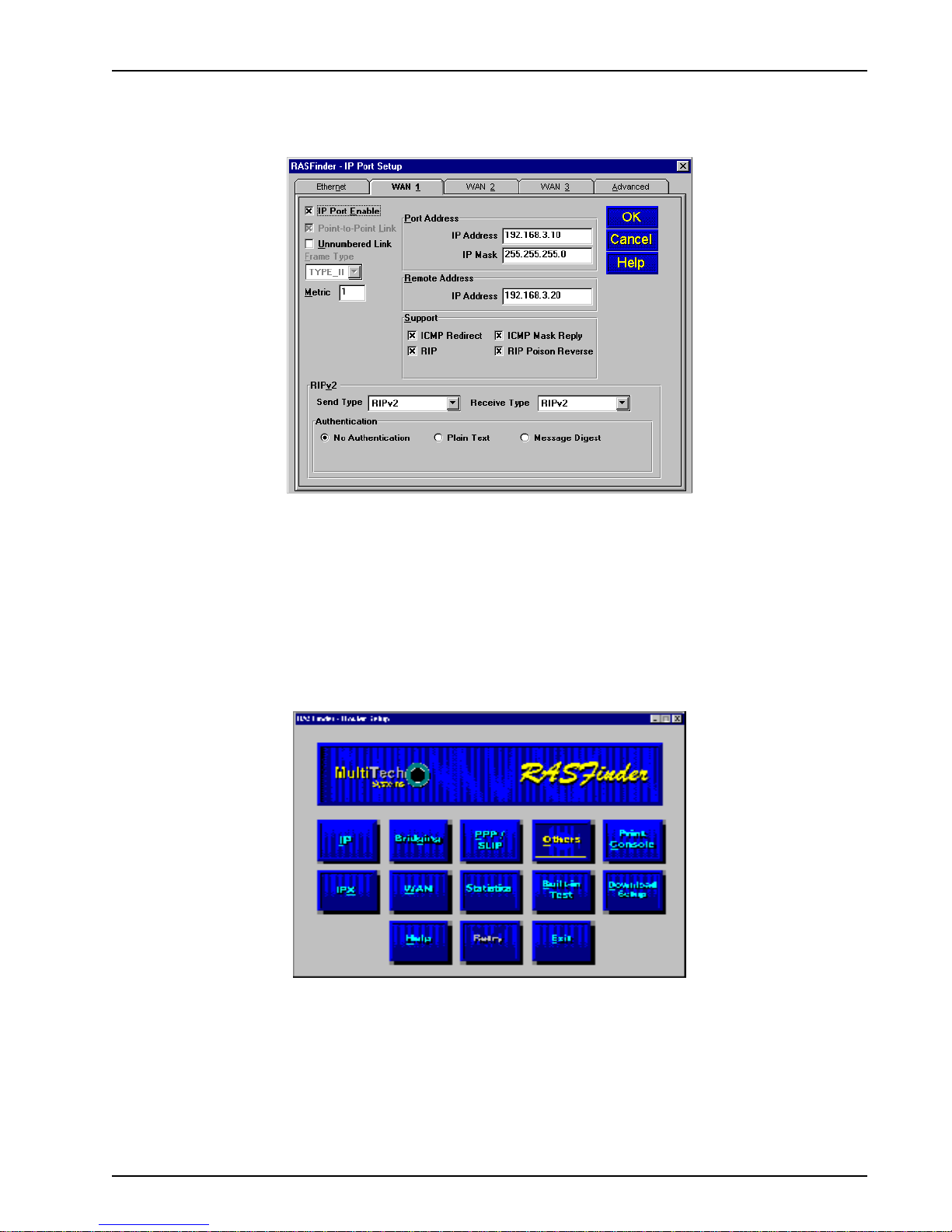
Chapter 3 - Software Loading and Configuration
6. On the WAN 1 tab, change the P ort Address and Remote Address groups to be on separate
networks from the Ethernet LAN port.
If you enabled MLPPP option on the PPP Port Setup dialog box, the IP addresses for all
three WAN ports have to be identical and the remote WAN port addresses have to be within the
same network and identical.
If you did not enable MLPPP option, the WAN port addresses have to be on a diff erent
network from the LAN port address and have to be different from each other .
7. Click on each of the WAN tabs and change the Port Address group and Remote Address group
to conform with the settings for WAN 1.
8. Click OK to return to the Main menu.
9. From the Main menu, click Download Setup button to write your new configuration to the
RASFinder. After your configuration is written to the RASFinder, you are returned to the Main
menu. Your RASFinder is now configured for LAN-to-LAN routing.
MTASR3-200
30
Page 31

Chapter 4 - RASFinder Software
Page 32

Introduction
This chapter describes the RASFinder software and explains how to mak e changes to the
configuration of your RASFinder . The major configuration parameters were established during the
loading of the software (Chapter 3) and initial configuration. The RASFinder software and
configuration utilities enable you to make changes to that initial configuration.
The RASFinder software enables you to refine your configuration based on your network
connections. The software is based on a main menu (RASFinder - Router Setup) that enables you to
consider all the parameters for a particular feature (e.g., IP or IPX protocol, Bridging, or setting up a
WAN port for PPP or SLIP protocol). These features, and others are discussed in detail in the
RASFinder Configuration section later in this chapter.
There are eight configuration utilities that offer additional functionality. The RASFinder
Configuration utility brings up the main menu (RASFinder - Router Setup) screen that provides you
with access to the buttons that enable you to view or change your initial configuration. The Download
Firmware utility enables you to download ne w v ersions of firmware when enhancements become
available . The Download Default Setup utility enables you to specify a set of parameters that are
unique to your unit. The Configuration Port Setup utility enables you to change the direct
connection of a PC to the Command Port on the RASFinder. The Uninstall
Configuration utility is designed to remove the software from your PC. The Upgrade RASFinder
utility will check to see if your RASFinder is using the latest software version and then, if necessary,
guide you through the upgrade process. The WAN Device Configuration utility opens the Print
Console, a terminal emulation program that enables you to configure the built-in modems. The
Remote User Data Base utility (supported through the command port) enables you to estab lish and
maintain a database of information about your remote users. You can add and remove remote users,
or edit existing user inf ormation in the database.
Chapter 4 - RASFinder Software
RASFinder
Your RASFinder software includes a context-sensitive Help system. Clicking the Help button on any
given dialog box provides definitions and recommended values for each button, option, and field on
that dialog box. In some instances, you will also see a list of related topics that can be displayed by
clicking green, underlined text. In addition, you can use the Index tab to search the entire Help
system for definitions and references to specific terms, fields, and recommend values where
applicable.
Before Y ou Begin
The RASFinder software operates in a Microsoft Windows® environment. Your RASFinder x.xx
program group, with all the utilities described above, is accessible by clicking Start | Programs |
RASFinder x.xx |
Computer (C:\Windows\Start Menu\Programs\RASFinder x.xx in Windows 98). The program
group is shown here:
(utility)
, or by double-clicking the utility icon in the program group in My
MTASR3-200
32
Page 33

RASFinder Setup
All changes to your RASFinder configuration are initiated through the RASFinder - Router Setup
menu. You can view or change your RASFinder configuration in Windo ws 98, 2000, XP and Windows
NT by clicking Start | Programs | RASFinder | Router Configuration, or double-clicking the Router
Configuration icon in the RASFinder program group, if it displays on your desktop. After loading, the
RASFinder - Router Setup menu displays.
Chapter 4 - RASFinder Software
The RASFinder - Router Setup menu consists of 13 buttons that enable y ou to display and change
your protocols, define the output of the RASFinder, perform network management functions, test the
communications link, print messages received from the target RASFinder , and do wnload setup
information to the RASFinder.
The two outer buttons in the bottom row are used to open the on-line Help system (RASFinder Setup
Help) and end (Exit) a Router Setup session. The middle (Retry) button remains inactive unless you
fail to connect to the target RASFinder .
MTASR3-200
33
Page 34

Typical Applications
The two basic applications for the MTASR3-200 RASFinder are (1) as a Remote Access Server
(RAS) to permit remote users to dial into a local area network and use the resources of that network
and (2) as a Router for LAN-to-LAN routing. The RASFinder defaults to a RAS configuration during
the initial software loading. Typical examples of both types of applications are presented in the
following paragr aphs.
RAS Applications
During the initial software installation, the RASFinder defaults to a remote access server (RAS)
configuration. For example, the WAN Ports are connected to individual phone lines and the ports are
then configured to answer incoming calls from remote locations. Two methods of identifying remote
users are provided in the RASFinder; 1) Remote Access Dial In User Server (RADIUS) and 2) a
Remote User Data Base utility in the RASFinder software.
RAS Application Using Radius
RADIUS is associated with a Radius server on the network which provides a security feature using a
single authentication server to centralize security on a network. The Remote User Data Base utility
identifies each user by user name, password and, if Call Back Security is enabled, a specific phone
number the RASFinder must call to establish the connection with the remote user.
Chapter 4 - RASFinder Software
Before remote users can dial into the network, either the Radius security services have to be
established, or each remote user must be idenfitied in the Remote User Data Base. Radius provides
a single secure server for all remote users; whereas the Remote User Data Base utility identifies
each user by User Name, Password, and a specific Call Back Number if Call Back Security is
enabled. Radius and the Remote User Data Base ha v e to have communication between the remote
user and the administrator either for setting up the data base or the security services to establish a
user profile. Radius also requires communication between the Radius administrator and the
RASFinder administrator to set up the security features and the Radius server address.
For a typical RAS application with a Radius server providing the network security, the Ethernet
(10Base-T or 10Base-2) port of the RASFinder is connected to the IP network, the Radius server is
on the backbone of the network, and the WAN ports of the RASFinder are connected to individual
phone lines. During initial software installation, the Default Parameters dialog bo x displays with both
IPX and IP protocols enabled and a default Ethernet IP address and (subnet) mask display ed. For a
RAS application using Radius on an Ethernet IP network, you would disable the IPX protocol and
then change the default LAN IP address and mask to the unique IP addressing scheme for y our
MTASR3-200
Figure 4-1. RAS Application
34
Page 35

Chapter 4 - RASFinder Software
network. The address assigned to the Ethernet port of the RASFinder can be any address that is
recognizable by your network’s backbone.
After you enter your LAN IP address inf ormation and three sequential WAN addresses have been
automatically placed in the Remote address for WAN 1, 2, and 3 fields, ensure that the Enab le IP
Routing on WAN 1, 2, and 3 are checked. This activates the WAN ports to receive calls from the
remote users. At this point, the software will be downloaded to the RASFinder and then you will need
to go in through the main menu and set up the conditions for the Radius security services.
To enable the Radius security services, you need to establish communications between the Radius
server and the RASFinder. The Radius security service options are defined on the Radius Setup
dialog box. To provide vendor-specific configuration for the Radius server, y ou need to bring up the
main menu, hit the PPP/SLIP button, and click the RADIUS b utton in the PPP Port Setup dialog box.
The Radius Setup dialog box enables the RADIUS option, establishes accounting, enables call if
security server is down, assigns a remote address using the RADIUS, provides a window for the
shared secret, and indicates the primary RADIUS server IP address. The new vendor specific
attributes and services that you establish for the RASFinder can not conflict with an y standard Radius
MTASR3-200
35
Page 36

Chapter 4 - RASFinder Software
attributes or any other custom attributes on the Radius Security Server. The Enab le RADIUS option
enables communication between the Radius server and the RASFinder. Enable Accounting option
activates the accounting features which allo w the Radius server to track the number of bytes sent
and received, login and logout times, port number, etc. The Allow Call If Security Server Down
feature can be used when the Remote User Data Base Utility is used as a backup database to the
Radius security services. The Assign Remote Address Using RADIUS feature enables the Radius
server to take over the addressing scheme of the WAN ports on the RASFinder .
The Shared Secret is an entry that must be obtained from the Radius network administrator and must
be the same as is used on the Radius security server. The RADIUS Primary Server Address is the IP
address of the Radius security server and in our typical RAS application, this address is 192.168.2.6.
If one or more backup Radius servers are used in your network, then their IP addresses need to be
entered in the Backup Server Address 1, 2, and/or 3 fields.
The Attribute Values Group at the bottom of the Radius Setup dialog box needs to have the v alue for
each of the three attributes and two services filled in.
The three new attributes are vendor-specific attributes and may have to be added to the Radius
server dictionary. The first attribute is Callback-Delay with a value of 224. The Radius server is set up
with a delay time for calling bac k the remote user. The Roaming-Callback attribute has a value of 225.
This attribute specifies a telephone number of where a remote user can be called back if he/she is
not at their usual telephone number provided in their user profile. The remote user would ha ve to give
that new phone number to the Radius network administrator so the RASFinder will know that the
remote user is at a different phone from the one in their user profile.
The Protocol Permissions Attribute has a value of 226 and the values associated with the attribute
are “1” for IP, “2” f or IPX, and “3” for Spanning Tree.
The Inbound User Service Type Attribute has a value of “10” and an associated value of “6”. This
attribute enables the remote user to hav e inbound access to the netw ork only; in other words, this
attribute
adds
inbound access to the remote user’s profile .
The Shell User Service Type Attribute has a value of “11” and also an associated value of ”6”.
After these new attributes are added to the Radius server and the user profile is established, a
remote user (in our typical RAS application with Radius, Remote User 1, for example) could call into
the RASFinder and identify themselves by their user name and passw ord. Remote User 1, in our
typical application, can initiate a dialup session by entering their User name and password in the
Dial-Up Networking (My Connection) dialog box and the phone number of the WAN port on the
RASFinder that User 1 is going to be connected to. In this application, remote user 1 could dial 7165565 to connect to WAN port number one on the RASFinder.
At this point, Remote User 1 has access to the services on the LAN. F or instance, if he/she wanted to
print a report, it could be sent to the printer and printed out as if Remote User 1 was on the local area
network.
MTASR3-200
36
Page 37

Chapter 4 - RASFinder Software
RAS Application using Remote User Database
The initial software loading process would be the same as for the RAS application using Radius,
except that now instead of setting up Radius parameters , you will assemble a Remote User
Database. A typical RAS application using the Remote User Database is shown in Figure 4-2.
Figure 4-2. RAS Application using Remote User Data Base
During the software loading process when the Default Parameters dialog box displays, both IPX and
IP protocols are enabled and a default Ethernet IP address and (subnet) mask are displayed in the IP
LAN group. For this RAS application, you would disable the IPX protocol and then change the default
LAN IP address and mask to the unique IP addressing scheme for your network. The address
assigned to your RASFinder’ s Ethernet port can be any address that is recognizable by your
network’s backbone.
In this typical RAS application, the IP network address is 192.168.2.xxx. For the purpose of this
discussion, we are assigning the IP address 192.168.2.10 to the Ethernet port on the RASFinder.
After this address is entered into the IP Address field of the Default P ar ameters dialog box, the next
three sequential IP addresses (192.168.2.11, 192.168.2.12, and 192.168.2.13) are assigned to the
WAN ports. These three IP addresses, in the same netw ork (with the Ethernet LAN), are associated
with the respective WAN ports so that when the remote users dial into the WAN ports, they
appear (to the rest of the IP network) at these respective addresses.
always
Before remote users can dial into the network, a user profile has to be set up in the proprietary
remote user database using the Remote User Data base utility. This data base utility is provided with
the RASFinder software. The RASFinder network administrator builds this database by adding
MTASR3-200
37
Page 38

Chapter 4 - RASFinder Software
information (for one remote user at a time) via the Add Users dialog bo x. The user name and
password in this application must be negotiated betw een the RASFinder administrator and each
remote user.
User names can be up to 39 characters long, with any printable characters; however, no spaces are
allowed within the names. In our dialog box (above), we are using the User Name “User2.” The letters
will appear as all caps in the Users List; however, dial-in applications will treat the user names as
case-insensitive strings, enabling the users to enter their user names as all uppercase, all lowercase,
or a mixture of uppercase and lowercase.
A User Password of up to 7 characters should be given each user. In the Call Back group, the Call
Back option should be enabled (checked) for security purposes. If ONLY this option is checked, the
remote user would be asked to supply the callback numbers when they dial into the RASFinder. If
Call Back Security Enabled is also checked, the administrator controls the callbac k numbers
through the Call Back Number field. In our typical application, User 2’s phone number is 875-5000;
therefore, we enter this number in the Call Back Number field. In the Dial In Ports, we have assigned
User2 to WAN Port 2 with phone number 716-5429 assigned to it. This phone n umber will have to be
entered in the Phone Number field on remote User 2’s dial-up netw orking (My Connection) dialog
box.
After the Add Users dialog box is filled in, you need to click the Rights button which brings up the
User Permissions dialog box.
The User Permissions dialog box enables you to assign protocol’s, user service type(s), time limits,
and time of day for each user to login. The Auto Protocols allow for no auto login, login via Telnet, or
RLogin and then direct the remote user to a specific host. The User Service Types defines how the
remote user is going to be allowed to use the network. For example, a remote user could be allo wed
MTASR3-200
38
Page 39

Chapter 4 - RASFinder Software
Inbound Permissions using Telnet, or Inbound using Rlogin. The time of day and days in which the
user can access the network are the final items in the User Permissions dialog bo x. Once this is
established for each user and the user database is loaded into the RASFinder, all the remote users
can dial into the network and access the network resources according to the restrictions/permissions
on this dialog box.
For example, Remote User2 (in our typical application) could initiate a dialup session by merely
entering their User name and password in the Dial-Up Networking (My Connection) dialog box (see
below) after having first set up a New Connection (called “My Connection”) and entering the phone
number of RASFinder WAN port 2 (716-5429), which is assigned to User2.
Once Remote User2 has connected and been authenticated, they have access to the services on the
LAN. For instance, if he/she wanted to print a report, it could be sent to the printer and printed out
just as if Remote User2 was on the local area network.
MTASR3-200
39
Page 40

Router Application
The second basic application for the RASFinder is LAN-to-LAN routing as shown in Figure 4-3. The
RASFinder is initially configured for a RAS application. To configure the RASFinder for a router
application, you hav e to change the WAN port addresses to be on a different network from the LAN
port. The remote WAN ports have to be on the same network as the local WAN ports. Finally, you
would have to change the Remote Port setup from a RAS application (Client only) to a routing
application (Client or LAN). If your routing application would benefit from having all three WAN ports
tied together to triple your WAN speed, then you would have to enable the MultiLink Point-to-Point
protocol (MLPPP) option.
Chapter 4 - RASFinder Software
Figure 4-3. Router Application
During initial software loading, you begin to configure the RASFinder for a routing application. A
typical routing application is shown in Figure 4-3 and will be used as an example in the following
discussion.
When you changed your LAN IP address in the Default Parameter s dialog box to your unique LAN
addressing structure and then try to change your Remote W AN port addresses to a different network
which you need for your routing application, you set up RAS as the default configur ation versus your
router configuration. The Default Parameters dialog box will not allo w you to change the addressing
scheme of the Remote WAN ports to your unique addressing structure for your routing application.
Therefore, you have to leave the Default Parameters dialog box set up for a RAS application initially
(during initial software installation and configuration); then later, from the main menu, you can switch
MTASR3-200
40
Page 41

Chapter 4 - RASFinder Software
from a RAS application to a routing application.
The PPP/SLIP (Point-to-Point/Serial Line Internet Protocol) button displays the PPP Port Setup
dialog box with the WAN 1 tab active. In the Remote Port Setup group in the lower right of the dialog
box, change from the Client only option to the Client or LAN (as shown below); this disables the
Client only option, and enables the RASFinder to communicate with
either
a remote client (PC) or a
LAN. The WAN 2 and WAN 3 tabs must have the Client or LAN enabled for both of these ports, too.
To bond the three WAN ports together, tripling the transfer rate between two LANs, click the Adv anced
tab and enable the MLPPP (MultiLink Point-to-Point Protocol) option. Then return to the main menu.
MTASR3-200
41
Page 42

Chapter 4 - RASFinder Software
You must now decide which protocol your LAN is using and choose that protocol from the main
menu. For example, to configure the RASFinder for IP, the P ort IP Address and IP Mask fields in the
IP Port Setup dialog box display the information that was entered earlier for your Default Parameters
during initial software loading. When you click the IP Port WAN tabs, the RAS LAN IP address
appears in the Port address field for the WAN ports. For a routing application, you have to change the
Port IP Addresses so the LAN port has a different address from the WAN port addresses, and you
may hav e to check that the WAN IP port addresses are identical (for MLPPP) and that the Remote IP
Addresses of the Remote WAN ports are on a
different
network. If y ou are not using MLPPP, then you
have to assign each WAN port a different address and ensure that the remote WAN ports are on a
different network.
In our routing example (Figure 4-3), the Corporate LAN was set up with the Ethernet IP address
192.168.2.1 and the three WAN ports were given the IP address 192.168.3.10. Whenever the y are
assigned the same IP address, the WAN ports are added together and look as one to the PSTN, and
the speed of the wide area network (normally the slowest cog in the system) is tripled to a value of
up to 168 Kbps.
After making these changes, you are returned to the main menu where you need to download this
new configuration to the RASFinder .
To set up the remote office LAN, go through the same process except point the W AN ports toward
the Corporate LAN. The remote WAN ports could be set up with an IP address of 192.168.3.20.
When this is accomplished, users at the remote office can receive their e-mail from the Corporate file
server and print their e-mail on their local printers.
MTASR3-200
42
Page 43

IP Setup
The IP Port Setup dialog box enables y ou to change the IP routing capabilities that were set up
during software installation. This dialog box has five tabs: Ethernet, WAN 1, WAN 2, WAN 3, and
Advanced.
Chapter 4 - RASFinder Software
The Ethernet tab enables you to configure v arious par ameters relating to the Ethernet port. F or
example, you can change the Ethernet port IP Address and IP mask; If necessary, you can change
the Ethernet Frame Type from Type II to SNAP; you can enable or disable various types of support,
set up RIPv2 parameters, and enable the type of A uthentication (if an y).
The Frame Type option defines the MAC layer frame encapsulation to be used for IP transmissions
from the specified port. The Ethernet port supports Type II and SNAP frames, but the WAN ports
support only Type II frames.
In the Support group, ICMP Redirect defines if the specified port is permitted to issue an ICMP
Redirect message to the source IP address. The most likely cause of this message is the delivery of
a datagram to a router that is not on the forwarding path to the destination address . This is often due
to a wrong configuration of the IP client sending the datagram. The pac ket causing the ICMP Redirect
message to be transmitted is forwarded to the appropriate router .
ICMP Mask Reply enables support for nodes on the connected networks to learn their subnet
masks.
RIP (Routing Information Protocol) enables RIP-based routing on the specified port, and is normally
enabled. However, RIP can be disabled if you are using WAN links in Dial-on-Demand mode. In such
links, disabling RIP will reduce traffic on the link as this will also disable periodic RIP broadcasts. RIP
routing on the port will be automatically turned off when Dial-on-Demand is enabled in PPP port
setup.
Finally, the RIP Poisoned Re verse option defines if Poisoned Re verse RIP messages are supported
on the specified port. Generation and processing of poisoned routes (RIP entries with their
respective metric set to 16 (defined as infinity) is enabled/disabled by this parameter. Poisoned
reverse is a method used by RIP to improve the rate of conv ergence of the routing tables of
interconnected IP routers. Routers supporting poisoned reverse that receive such RIPs ignore the
entries set to 16 and thus prevent the propagation of unnecessary (and often incorrect when a
topology change occurs) information which in turn speeds up the rate at which RIP will correctly map
the current network topology.
MTASR3-200
43
Page 44

Chapter 4 - RASFinder Software
Routing Information Protocol, Version 2 (RIPv2)
RIPv2 has enhanced “explicit” netmask information and supports several new features including
external route tags, subnet masks, next-hop addresses, and authentication. Subnet mask information
makes RIP more useful in a variety of environments and enab les the use of variable subnet masks
on the network. Support for next-hop addresses permits the optimization of routes in an environment
that uses multiple routing protocols. For example, when RIPv2 is being run on a network along with
another IGP, and one router is running both protocols, then that router can indicate to the other RIPv2
routers that a better next-hop than itself e xists for a given destination.
RIPv2 packet setup is accomplished at the bottom of each of the WAN tabs. The RIPv2 group
enables you to set up the send and receive packet types as either RIPv2 (default), RIPv1
Compatible, or None. You can also set up RIPv2 authentication here.
The Authentication subgroup is the RIPv2 mechanism for authenticating the sender of the routing
eliminates the vulnerability of the routing infrastructure. This authentication scheme is essentially the
same mechanism provided by OSPF. Currently, only a plain-text password is defined for
authentication.
For Plain Text RIPv2 authentication, the maximum length of the password is 16 char acters; however ,
Message Digest authentication can have a key id field of up to 50 characters.
On the WAN port tabs you can change any parameters that are active , including most of those
discussed (above) f or the Ethernet tab plus the WAN IP Port Enable, Unnumbered Link, and the
Remote IP Address.
WAN 1, WAN 2, and W AN 3 Tabs
If you enable the IP routing master control on the Advanced tab but disable the control on this tab, all
IP packets received or to be transmitted on this WAN port will be discarded. Even if bridging is
enabled, the packets will not get across the link.
The Unnumbered Link option can be selected (checked) for the WAN ports for point-to-point links.
When selected, it disables the Port Address and Remote Address groups. Unnumbered links are
useful only between two routers; in this case, local and remote. When running RIP over a PPP link,
both ends of the link must be either unnumbered or numbered with the same IP subnet. An
advantage of not assigning an IP address to each WAN port is that you conserve valuable network
and subnet numbers.
Remote IP Address defines the IP address for the destination end of a point-to-point link and is
necessary only if the selected WAN port has been enabled f or point-to-point operation. Note that the
MTASR3-200
44
Page 45

Chapter 4 - RASFinder Software
remote IP address must fall within the same IP network as the local WAN IP address.
The Advanced tab is used to enable IP routing and RIP authentication and defines ho w the Dynamic
Host Configuration Protocol (DHCP) and Domain Name System (DNS) servers are to be used. This
tab is also used to set up the default route, any filters, OSPF (Open Shortest Path First), and Static
Routes. This tab also enables you to set up various configuration options for IP routing protocol, and
any options selected here apply to all ports on which IP routing takes place.
The Routing option is normally checked; however, if you do not wish to have IP packets routed, then
uncheck this item. If IP routing is disabled and bridging is enabled, IP packets are bridged; i.e., IP
packets are transf erred.
The RIP option enables RIP based routing. RIP (Routing Information Protocol) is a protocol used
among routers to exchange routing table inf ormation. RIP is the most common protocol used in both
IP and IPX networks. It is also used internally by client workstations in IPX networks to obtain routes
(shortest, or otherwise) to any distant network. RIP based routing should normally be enabled. It can
be disabled, however, if you are using WAN links in Dial on Demand mode. For DOD links, disabling
RIP will reduce traffic on the link as it will also disable periodic RIP broadcasts. RIP routing on a
given port will be automatically turned off when Dial on Demand is enabled on the PPP Port Setup
tab for the WAN port.
The DHCP (Dynamic Host Configuration Protocol) group enables you to set up the WAN ports as
client-only. Then, a PPP client connected to the WAN port will be on the same IP network as the LAN
port of the RASFinder. This feature can save some extra IP addresses that otherwise w ould have
been taken up by the WAN port. Enabling the Client option allows the RASFinder to dynamically get
an IP address for a PPP client coming up on one of its “Client-only” WAN ports. When this option is
enabled, there must be a DHCP server or a DHCP relay agent on the connected LAN in order for the
RASFinder to acquire an appropriate IP address.
In most cases, you should not have to change any of the timers (i.e., def ault TTL, reassembly timeout, RIP response time and RIP route aging time).
When the router is configured for remote access, the DNS Resolver needs to be enab led so that
applications such as the terminal server will support Domain Names. The dotted decimal IP address
of the Local DNS server should be entered in the field provided.
The Static Routes feature enables a remote netw ork PC to access a specific workstation or
peripheral device on another network through a predefined route (static route). Static routing is
MTASR3-200
45
Page 46

Chapter 4 - RASFinder Software
normally used when a part of an internetwork can be reached by only one particular path. Static
routes are manually configured routes that specify the transmission path a data packet must follow
based on the data packet’s destination address. A static route could enable a client pc on the
manufacturing network to send a document to the printer on the corporate network. This static route
is shown in the top network in Figure 4-4. A static route can also use an unnumbered link to provide
a particular route from a remote client device to a specific device on another network. The
unnumbered link is shown in the middle network in Figure 4-4.
Figure 4-4. Static Routes
In our first example above , where a data packet from the remote client PC on the manufacturing
network is being sent to the corporate printer, the Static Routes Setup dialog box would contain an
address of 200.1.1.0 in the IP Address field and a gateway address of 200.2.10.2. The Unnumbered
option would be left unchecked in this example. The IP Address field contains the address of the
target host or network, a PC on the manufacturing network. The Gateway Address is the address of
the local router on the manufacturing network (200.2.10.2) on the next hop to ward the target host.
The Address Mask is the IP subnetwork mask (255.255.255.0) of the target host. The Port field is
inactive, grey ed out in this example. Metric is the hop count (1) to the target host.
Now, for our second example of an unnumbered link where we want a server on a remote network to
appear as a device on a router on the corporate LAN that is pointed toward the Internet. Let say that
the Manuals Server on the Publications Network contains the released manuals that a customer can
down load from the corporate network. So in order to have the Manuals Server appear on the
Internet, we need to set up the corporate RASFinder with an unnumbered link and for the purposes
of our example, lets use WAN 2. Also, the Internet router on the Corporate LAN will have a def ault
route of 192.168.2.224 with a subnet Address Mask of 255.255.255.224, and a Gatewa y Address of
192.168.2.10.
So, for this application to w ork, y ou need to set up a default route on the Corporate RASFinder of
MTASR3-200
46
Page 47

Chapter 4 - RASFinder Software
192.168.2.220 which is pointing at the Internet router. You then, need to go into the IP Port Setup
dialog box, select the WAN 2 tab, and activate the Unnumbered Link option. When you do this, the
Port Address and the Remote Address groups become inactive. You should turn off RIP in the
Support group on WAN 2 so that the RASFinder does not try to broadcast RIP packets which tak e up
unnecessary bandwidth. Then y ou need to check the PPP/SLIP button on the Main menu and
ensure that the Remote Port Setup group for WAN 2 is set to Client or LAN.
Now go back to the IP Port Setup dialog box and hit on the Advance tab, then click on the Static
Routes button. This brings up a blank IP Static Routes dialog bo x, hit on the Add button to bring up
the Static Routes Setup dialog box and when you enab le the Unnumbered option, the Port option
becomes active and the Gateway Address option becomes inactive.
Now, for the IP Address field we want the address of the Internet router on the Corporate LAN which
in our unnumbered example is 192.168.2.220. In order for the Manuals server on the Publications
network to appear on the Corporate LAN, we need to subnet the Manuals server with an Address
Mask of 255.255.255.224. The Port option identifies the WAN port on the Corporate RASFinder that
is unnumbered. In our example, WAN 2 is the port. The Metric hop count remains at one (1).
When we click on the OK button for the Static Routes Setup dialog box, the IP Static Routes dialog
box now displays the two examples of static routes.
To complete the Static Route application, the Publications network RASFinder or router, depending
on the type of device used on the network would need a def ault route of 192.168.2.226 that is looking
at the Manuals Server. The Ethernet port IP address could be 192.168.2.225 with a net mask of
255.255.255.224.
MTASR3-200
47
Page 48

Filters
Chapter 4 - RASFinder Software
The network administrator can set up filters on the RASFinder for better control. Filtering can be used
when you want to block all packets originating from a specific destination (called source address
filtering) or all packets heading for a particular destination (called destination address filtering). Filters
can be set up to exclude packets of a particular protocol (TCP or UDP) or any particular field in a
LAN packet. The IP Filtering Setup dialog box lists the port, address, or Internet Control Message
Protocol (ICMP) filtering for the IP protocol.
Initially, the filtering list window , i.e., the window area that displays the Type, Port, Protocol, and
Protocol Port information is blank. This information displays in the window when the Add/Edit IP Port
or Address Filter dialog box is filled out.
Note: When filters are installed, the RASFinder needs to do e xtra processing (i.e., it needs to look
into each packet that has to be routed or bridged). Thus, installing too many filters may lead to
performance degradation.
Port filtering filters or forwards IP pack ets based on their specific purpose; i.e., whether they are
Telnet (TCP based) or TFTP (UDP based) packets. Address filtering filters or forwards packets
based on their source or destination IP address. Separate filtering support is provided for specific
kinds of received ICMP packets.
The filtering list window on the Port Filtering tab (above) displays the filter Type , the physical Port
(LAN, or one of the WAN ports), the Protocol (TCP or UDP), and the Protocol Port. On the Address
Filtering tab (not shown), the Protocol and Protocol Port columns are replaced by IP Address.
To add or edit a filter listing, the Add/Edit IP Port (Address) Filter dialog box is used. This dialog
box enables you to create an entry which is then displayed in the filtering list window. In the example
MTASR3-200
48
Page 49

Chapter 4 - RASFinder Software
Add/Edit IP Port Filter dialog box, the protocol that is going to be filterred is TCP, the physical port on
which the filtering is going to take place is the LAN port, the protocol port is telnet which translates
into protocol port number 0023 in the filtering list window, and the filter type is Filter on Destination
Port which means to drop all IP packets whose destination protocol port is telnet.
Address filtering uses the IP address in the IP Address field (example, packets with address
192.168.2.40), applies filtering to the physical port listed in the Physical Port field (LAN), and if the
Filter Type is Filter on Destination Address that means that all packets with an IP address of
192.168.2.40 that are destined for the LAN port are blocked.
ICMP filtering provides separate filtering support for specific kinds of received ICMP packets. ICMP
filtering is used in IP networks as an internal protocol for nodes to exchange control and diagnostic
information. Applications normally do not use ICMP filtering for any purpose.
You can select ICMP filtering on your LAN or WAN ports and the type of filtering on each port by
choosing the filtering type from the ICMP Pack et Types list.
MTASR3-200
49
Page 50

IPX Setup
The IPX Virtual Port Setup dialog box is used to control the four frame types and set up the three
WAN ports of the RASFinder. The Advanced tab opens an IPX general setup window used to enable
or disable IPX routing and autolearn of Ethernet network numbers; also, the distributed name of the
RASFinder can be designated here.
Chapter 4 - RASFinder Software
In IPX based networks using Ethernet, LAN segments can support the use of four diff erent Ethernet
frame formats over the same physical link (provided each frame type has a unique network address
as a virtual port).
The three WAN tabs allow you to enable or disab le IPX routing on the WAN ports, change the
network numbers for the WAN ports, change the default RIP and SAP timers, and optimiz e the
bandwidth. The IPX WAN network number has to be the same on both ends of the link and must be
unique throughout the internetwork. If a WAN port is configured in a point-to-point operation, both
WAN network numbers ha v e to be the same and unique .
NetBIOS, when enabled, enables the transport of Novell encapsulated NetBIOS pack ets on the
specified virtual IPX port. Ref er to Novell documentation regarding NetBIOS operation over NetWare
based LANs. The Hops text box defines the distance, in hops, for the routing of Novell encapsulated
NetBIOS frames on the specified virtual IPX port, and the recommended value is 8.
Periodic RIP (Routing Information Protocol) refers to broadcasts transmitted from the RIP virtual IPX
port at a given frequency so all routers on the internetwork maintain consistent routing tables.
Increasing the frequency of RIP broadcasts can consume excessive bandwidth, especially on lowspeed WAN links. Sixty seconds is the recommended interval between RIP broadcasts. The default
RIP timer settings should work well for most applications.
Periodic SAP (Service Advertisement Protocol) is used in IPX based networks to enable servers
(application servers, file servers, print servers, communication servers, etc.) to advertise their
presence on the internetwork. Routers use these advertisements to build up tables listing the servers
so they can then advertise these servers on the local segments and provide routers to the server.
Client workstations can request a list of these servers from the router. The default SAP timer settings
should work well for most applications.
MTASR3-200
50
Page 51

Bandwidth Optimization Group
Discard Serialization Packets, when enabled (checked), causes the IPX router to discard Novell
Netware File Server serialization security frames received from the specified virtual IPX port. Novell
Netware File Servers implement broadcast frames, often referred to as security frames , that contain
serialization information regarding the license of the file server executable. This feature permits
filtering of these broadcasts to help reduce WAN traffic and is not intended to interfere with copyright
protection mechanisms. This feature is automatically turned on when Dial-On-Demand is enabled in
PPP port setup.
The Advanced tab controls the master routing of the protocol and auto learn of Ethernet network
numbers, defines the broadcast name of the RASFinder , and enables IPX filtering.
Chapter 4 - RASFinder Software
If bridging of IPX packets is desired, IPX routing must be disabled and frame type support for the
frame type must be enabled.
If there is a server on the local segment, then IPX network number auto learn should be enabled. If
there is no server, or if f or some reason the RASFinder comes up before the server does, the
RASFinder will default to some random network numbers after a short period of time.
MTASR3-200
51
Page 52

IPX Filters
The network administrator can set up filters on the RASFinder for better control. IPX packet filtering
can be set up to selectively filter or forward packets based on the IPX address.
Filtering can be used when you want to block all packets originating from a specific destination
(called source address filtering) or all packets heading for a particular destination (called destination
address filtering). Filters can be set up to exclude packets of a specific port. The IPX Filtering Setup
dialog box lists the filter type, port, and IPX address. Initially, the filtering list window, i.e., the window
area that displays the Filter Type, Port, and IPX Address information is blank. This information
displays in the window when the Add/Edit IPX filter dialog box is filled out.
Chapter 4 - RASFinder Software
Note: When filters are installed, the RASFinder needs to do e xtra processing (i.e., it needs to look
into each packet that has to be routed or bridged). Thus, installing too many filters may lead to
performance degradation.
The Add or Edit IPX Filter dialog box allows you to enter a network number and node number, and
define a socket number, physical port, and filter type. The Network Number defines the ph ysical port
which is defined by turning off AutoLearn Ethernet Network Numbers option in the IPX Virtual Port
Setup dialog box under the Advanced tab. The Node Number is a 12-digit alphanumeric MAC
Address of the Ethernet NIC that is providing your Ethernet interface. The Node Number is defined in
the IP Configuration dialog box under the Adapter Address in the Ethernet Adapter Information group.
The Adapter Address is presented with dashes between each set of two alphanumeric digits. These
dashes can not be used in the Node Number. The IP Configuration dialog box is accessed from a
DOS prompt by enterring winipcfg.
The socket number, physical port, and filter type are provided in drop down lists. Three socket
number selection are provided; NCP, RIP, and SAP. The physical port lists the available port for
which filtering can be accomplished; LAN and the three WAN ports. The filter type defines whether
you are going to forw ard or filter depending on the source or destination address .
MTASR3-200
52
Page 53

Spanning T ree Setup
This dialog box lets you configure the parameters f or transparent bridging or bridging using Spanning
Tree Algorithm as specified in IEEE 802.1d standard. Transparent bridging occurs between two
remote Ethernet LANs.
Spanning Tree Algorithm is a protocol specified by the IEEE 802.1d standard for use by bridges to
perform bridging. Bridges implementing this protocol interact with each other so as to prevent
bridging-loops in an internetwork with redundant links to the same networks. This algorithm also
allows for automatic use of alternative routes (provided there are redundant paths to the destination)
in case the original route is unavailable f or some reason.
Chapter 4 - RASFinder Software
Bridging needs to be enabled to support networking protocols such as NetBIOS. Howe ver, if y ou are
using only IP and IPX, the RASFinder will operate more efficiently if you leav e bridging disabled.
With Spanning Tree bridging, the default initial state of each port in the List Of Logical WANs is
“forwarding.” Other availab le options include: “listening,” “learning,” “blocking,” and “disabled.” Cost (or
Path Cost) indicates the relative cost of using a given port to bridge to a remote network and is
defined as 1,000 divided by the megabit data rate of the Network connected to the specified port. The
default value for the LAN port is 100, and the value assigned for each of the WAN ports is 1000.
The Filters b utton enab les the construction of a filtering database. Packets whose Ethernet source
address or destination address is not found in the filtering database will either be filtered or
forwarded, depending on the setting of the Default Action field, with a def ault setting of “forward.”
Filtering can be used when you want to block all packets originating from a specific destination
(called source address filtering) or all packets heading for a particular destination (called destination
address filtering). Filters can be set up to exclude packets of a specific port. The Spanning Tree
Filtering Setup dialog box lists the filters by filter type , port, and Ethernet address. Initially, the
filtering list widow, i.e., the window area that displays the Filter Type, Port, and Ethernet Address
information is blank. This information displays in the window when the Add/Edit Spanning Tree Filter
dialog box is filled out.
Note: When filters are installed, the RASFinder needs to do e xtra processing (i.e., it needs to look
into each packet that has to be routed or bridged). Thus, installing too many filters may lead to
MTASR3-200
53
Page 54

Chapter 4 - RASFinder Software
performance degradation.
The add or edit Spanning T ree Filter dialog box allows you to enter the Ethernet address (for
example 15345678) to which you w ant to apply filtering, the ph ysical port (W AN 1) on which the
filtering is going to be applied, and the filter type in our example of Filter Destingation Address.
This means that all packets with a destination address of 15345678 going to WAN 1 are dropped.
MTASR3-200
54
Page 55

WAN Port Setup
The WAN Port Setup dialog box controls how each WAN port is configured. Since each port has a
built-in modem, the default Mode, “Asynchronous” cannot be changed. The Connection Method can
be set to either Answering or Dialing. If Dialing is enabled, then the number to be dialed has to be
entered in the Dial Number field. The entry Multi-Tech 56K Socket Modem in the Modem Types
field refers to the built-in modem installed in the RASFinder.
Chapter 4 - RASFinder Software
If either WAN 1 or WAN 2 needs dial backup in case it loses carrier (i.e., the Carrier signal, DCD,
goes down), then WAN 3 can be used (dedicated) for this purpose. The Needs Dial Backup check
box on the appropriate WAN tab (WAN 1 or WAN 2) must be enabled, then the dial backup number
must be entered on the Backup Port tab (after it is active); when it is used for backup, WAN 3 will no
longer be available for routing or RAS.
The Script button provides access to the scripting options. The Script Dialog menu enables you to
edit, compile and download scripts. A script file (a text file containing a sequence of commands; refer
to Appendix B) can be used to automate certain RASFinder operations. The Script Enable or
Restart Script On Communications Failure option can be used to either start scripting or restart a
script upon failure.
The RASFinder has built-in support for Multi-Tech Communication Services Interface Server (MCSI,
NASI, NCSI, or AG server) if every asynchronous communication line across the internetwork has a
unique MCSI name. If y ou set the Connection Method f or Answering, the Asynchronous Gateway
Server (AG Server) group becomes active , enabling you to set the General Name and Specific
Name of the interface corresponding to that specific Port (WAN 1, WAN 2, or WAN 3). The name of
the AG Server is assumed to be the same as the IPX router name (or at least the first eight
characters of the Router Name entered on the IPX Advanced tab). The General Name can be any 8
alphanumeric characters (with no question marks) and the Specific Name can be any 14
alphanumeric characters (with no question marks).
Setting the Connection Method for Answering also activ ates the T erminal Server group, where you
need to enter, in the field pro vided, the dotted decimal IP Address of the default Telnet server.
MTASR3-200
55
Page 56

Point-to-Point Setup
The PPP Port Setup dialog box controls the WAN port protocol, dial on demand, and remote port
setup. The WAN port protocol can be either Point-to-Point Protocol (PPP) or Serial Line Internet
Protocol (SLIP). Of these two protocols, PPP is the more robust as it enables the endpoints to
negotiate the use of the link and protocol parameters in a standardized wa y and also enab les for
standardized encapsulation of the packets. SLIP is an older protocol which requires manual
authentication using a script.
Chapter 4 - RASFinder Software
PPP is the default protocol. The PPP software in the RASFinder internally negotiates the use of a
suitable authentication protocol (PAP or CHAP) with the remote router or remote access client
software. When either PAP or CHAP (or both) is enabled, the RASFinder expects the peer (the client
on the other side of the WAN link) to be configured with a User Name and Password combination that
is in the RASFinder’s User Database . The User Name and Pass w ord are both ASCII character
strings that can be up to 30 characters long. Ho w ever, for router-to-router connections, authentication
is normally not used and the User Name and Passw ord fields are empty.
The Periodic Timer option shows the interval between authentication chec ks. The recommended
value is 10 seconds. The Number of Retries option, with a recommended value of 5, refers to the
number of retries during each PAP or CHAP authentication check.
If SLIP is to be used on one of the WAN ports, then select the SLIP Enable option on the
corresponding tab and PPP will be disabled automatically. If the TCP/IP header is to be compressed
using VJC compression, then chec k the CSLIP (Van Jacobson Compression) option. (Note: on
answering WAN ports, the RASFinder can detect the type of connection -- PPP or SLIP.)
You can set up the RASFinder to bring down the connection on the W AN link when there is no real
data traffic on the line; the router will then automatically bring up the WAN link when data is a vailable
to go across the link.
In the Remote Port Setup group, the Client only option saves IP addresses in a RAS application
because the remote node (a dial-in client) becomes a virtual extension of the Ethernet LAN. For
Routing, however, you must check the Client or LAN option, in which case there will be no saving of
IP addresses on the WAN ports.
MTASR3-200
56
Page 57

Applications
In addition to local configuration, the RASFinder supports various applications that enable remote
viewing and changing of the configuration from anywhere on the connected internetwork. T o manage
these applications, click Others on the Router Setup menu.
The Applications Setup dialog box appears.
Chapter 4 - RASFinder Software
Verify that the desired applications are enabled (checked). The default condition is all applications are
checked. To disable a given application, click to uncheck the check box and disable support.
For more information on using these remote configuration applications, click the on-line Help button
or refer to Chapter 7, Remote Configuration and Management.
Diagnostics
The RASFinder is equipped with a built-in diagnostics utility that can be accessed by a PC cabled
directly to the command port (remote users cannot access the diagnostics). Click the Built-in T est
button on the RASFinder Setup menu and the Diagnostics dialog bo x displays.
In the T est Port group, select the port (Ethernet, WAN 1, WAN 2, or WAN 3) y ou want to test, then
click the Test button to start diagnostic testing.
For additional details and parameters about specific fields in the Diagnostics dialog box, click the
on-line Help button.
MTASR3-200
57
Page 58

Client
The information provided in this section enables multiple users to configure their PCs to access the
LAN through a RASFinder. The RASFinder was configured by the administrator who, while installing
the software, determined that the RASFinder would either automatically assign Internet (IP)
addresses, or require that they be assigned manually to each client PC. Also, the administrator
assigned an IP address to the RASFinder’s Ethernet port, and assigned user names and passwords
to the WAN links. All these factors play a role in client configuration. Make certain that you are aware
of the decisions made prior to setting up client PCs.
PC
To access the RASFinder, your PC must have communications capability including hardware such as
a Dial Up Network Adapter/modem and any necessary software.
Make certain that your Dial Up Network Adapter IP addressing is dynamically assigned (default). If it
is, then the only information you may be required to obtain is the IP address of your organization’s
Domain Name Server (DNS) - if DNS has been enabled on the IP Setup dialog box, Adv anced tab.
Note: In cases where the IP address has been manually assigned, you will need to know the IP
address of the RASFinder (Gateway address) in addition to the organization’s Domain Name.
Chapter 4 - RASFinder Software
Checklist
A checklist is included so that you can record all the pertinent information required for the connection
between your PC and the RASFinder . Keep this as a reference for future upgr ades .
Use the following checklist to record all the configuration settings for future use:
MTASR3-200
58
Page 59

Chapter 5 - RAS Dial-Out Redirector
Page 60

Chapter 5 - RAS Dial-Out Redirector
Introduction
Multi-Tech’s Remote Access Server for Microsoft network users enables users to dial-out and fax-out
through your MTASR3-200. Remote Access Solution software uses Multi-Tech’ s Communications
Services Interface (MCSI - pronounced “Mik-see”). MCSI is a software redirector which complies
with MCSI/NCSI/NASI defacto standards for software redirection.
The Windows© version of MCSI, called WINMCSI, is supported on Windows 98 and NT platforms.
MCSI2000 is supported on Windows 2000 and XP operating systems. MCSI 2000 is documented in
a separate sofware installation guide on your product CD. Refer to the Multi-Tech Communication
Serial Interface for Windo ws 2000 and XP Software installation Guide for information on MCSI2000.
Since WINMCSI provides data communications connectivity, it needs to be installed and operating
before your data communications application softw are is started.
Installing and Configuring the WINMCSI Modem-Sharing
Software
The WINMCSI modem-sharing software (included on the CD) manages access to an Asynchronous
Gatewa y (AG) for outbound calls. It allows Windows communications software packages that do not
support INT6B or INT14 to connect to a gateway. It also detects other compatible communications
servers (e.g., RASs) on your network and displays the resources they provide to eligible LAN users.
1. Po wer on your client PC and log in to your LAN.
2. Start Windows.
3. Insert the Multi-Tech RASFinder CD into your CD-ROM drive. The RASFinder Splash screen
displays.
4. Click on Install MCSI Utility button. A second window opens, choose the Windows operating
system you wish to install.
5. The Welcome screen displays.
Click Next to proceed with the installation.
MTASR3-200
60
Page 61

Chapter 5 - RAS Dial-Out Redirector
6. The Choose Destination Location screen displays .
Click Next to accept the Destination Folder, or click Browse to select a different destination.
7. The Select Program Folder screen displays.
Click Next to accept the ne w f older designation, or choose an e xisting f older from the list pro vided.
8. The Choose Network Type screen displays.
Selections include IPX, NetBIOS, and IP (default is IPX). Click IP and then click Next to
proceed.
MTASR3-200
61
Page 62

Chapter 5 - RAS Dial-Out Redirector
Note: If the software redirector is set up as IPX, the IPX option must be selected in the
Applications Setup dialog box. If the software redirector is set up as IP, the IP option must be
selected.
9. The COM Port to MCSI Mapping window displays.
Click Add P ort to add a port to the MCSI Port list.
If you want a specific line, click a COM port in the MCSI Port list, then click the line to which you
want to map that particular COM port. The status message "Mapped to MCSI" should appear
above the MCSI Port list.
Click Remove Port to permanently remove a port from the Local Port list box.
Click Unmap to unmap a line.
Click Search to search for lines on a server.
Click Close when finished.
At this time your WINMCSI software installation is complete. Proceed to the next section,
“Running the WINMCSI Workstation Software”.
MTASR3-200
62
Page 63

Chapter 5 - RAS Dial-Out Redirector
Running the WINMCSI Workstation Software
WINMCSI has a workstation portion of the software that LAN users run and use to log onto the
communications server prior to running datacomm software on their client PCs. The following steps
guide you through this process.
1. To start WINMCSI, click Start | Programs | MultiTech MCSI | ComMap. The ComMap for
Windows window displays.
The buttons from left to right are: Login, Logout, Map, Unmap, and Exit.:
3. To setup ComMap, click Setup.
Click the Network T ype command. The Network Type dialog box displays. Your current network
type is highlighted. You can change the network type by clicking the option button appropriate for
your network. Click OK when finished. You must restart Windows if you change this setting.
Note: Do not change the network type unless you have changed the network. Also, make sure
that your SYSTEM.INI file contains the device drivers specific to the selected network type.
Click the Connect Timer command. The MCSI Connect Timer dialog box displays. The default
value of the connect timer is shown in the Enter Connect Timer Value field. To change the value
of the connect timer, type in a diff erent value. Click OK when finished.
Click the Baud Change command. The ComMap Baud Change message displays. If baud
change by an application is permitted, then this command is checked in the Setup Menu. If baud
change is unchecked in the Setup Menu, then an application cannot change the baud rate (or
other port parameters). Answ er the message appropriately.
Click the Default Login command. The Default Login Parameters dialog box displays. Use
this dialog box to select a specific RAS to which you want to log into next time Windows is
loaded. Clic k a RAS from the Available Servers box. If there are no servers in the Available
Servers box, then click the Search button. Type in a User Name and Password (optional) in
their respective fields. Click OK when finished.
ComMap saves these login parameters in y our COMMCSI.INI file.
Note: You cannot directly edit the COMMCSI.INI file using a text editor because the password
field is encrypted.
MTASR3-200
63
Page 64

Chapter 5 - RAS Dial-Out Redirector
4. If you have not logged into the network, do so now by clicking File | Login, or click Login. The
MCSI Login window displays.
The Av ailable Servers box lists the names of the available servers. Click the name of the server
to which you want to attach, type a User Name and Password in their respectiv e fields, and then
click Login. A window displays stating that your login was successful. Click OK. If there are no
servers listed in the Av ailable Servers box, then click Search to search for a server.
5. At the ComMap for Windows main window, view your log status by clicking File | Log Status.
The MCSI Login Status window displays.
This window shows the name of the server to which you are logged in and the name with which
you logged in. Click Close when you are finished.
6. At the ComMap for Windows main window (to map a COM port through MCSI) click Map | Map.
The COM Port to MCSI Mapping window displays.
MTASR3-200
64
Page 65

Chapter 5 - RAS Dial-Out Redirector
Note: Windows 98/95 users will ha ve two additional buttons in this box, the Add Port and the
Remove Port buttons. You must click the Add Port button to view Local Ports. Click the
Remove Port button to remov e Local Ports.
If you want to get the first available line, click the Map button and then click the Close button and
go to step 7.
If you want a specific line, click a COM Port in the Local Port list box, then click the line to which
you want to map that particular COM Port. The status message "Mapped to MCSI" should
appear above the Local Port list box.
Click Unmap if you want to unmap a line .
Click Search to search for lines on a server.
Click Close when finished.
7. To view a list of mapped COM ports, click Map | Map List, or click the Map button. Click Close
when finished.
Below is an example of the Window's Terminal application's (shipped with all versions of
Windows) Communications dialog box. After mapping your COM Ports with ComMap for
Windows, you can check your connectivity and configure your ports with Windows Terminal. It is
recommended that you use the settings shown in the e xample below (in the example COM1 is
shown).
8. To unmap a COM port, click Unmap | Unmap, or click the Unmap button. Click the listing you
want to unmap and then click Unmap.
9. To logout from the network, click File | Logout, or click the Logout button.
10. To exit from WINMCSI, click File | Exit, or click the Exit button. Otherwise you may minimize the
screen to minimize WINMCSI to an icon.
MTASR3-200
65
Page 66

Chapter 6 - Remote Configuration and Management
Page 67

Introduction
This chapter provides procedures for vie wing or changing the configuration of a remote unit. Tw o
methods are provided to access a remote unit; the first method is modem-based and the second
method uses IP. Within the IP method, three different applications can be used: 1) LAN-Based
configuration using TFTP (Trivial File Transfer Protocol), 2) T elnet as a client application, or 3) a
standard Web browser on the Internet.
Remote Configuration
Remote configuration requires that the RASFinder software be installed on the local PC. The local
PC then controls the remote RASFinder either through the modem connection or over the LAN.
Modem-Based
To remotely configure a RASFinder, a local PC needs to be connected to a dial-up line and the
RASFinder software configured to call the remote RASFinder. The remote RASFinder needs to have
a modem connected to a dial-up line and the Command port. Once the connection to the remote unit
is made, you can change the configuration as required. Once the configuration is changed, you can
download the new configuration to the remote RASFinder. Perform the following steps to remotely
configure a RASFinder through a modem connection.
Chapter 6 - Remote Configuration and Management
1 . At the remote site, remove the serial cable from the PC to the Command port connector on the
back panel of the RASFinder .
2. At the remote site, connect a special cable (Remote Configuration Cable) from the Command
port connector on the back panel of the RASFinder to the RS-232 connector on the modem. The
special cable is a serial cable with male connectors on both ends. Refer to Appendix A for cable
details.
a. Connect the modem to your local telephone line.
b. Provide your telephone number to the person verifying y our configuration.
c. Configure the remote modem for 19200 baud and turn on Force DTR.
3 . At the main site, connect your local PC to a modem that is connected to a dial-up line.
4. Install the RASFinder software on the local PC. When installed, click Start | Programs |
RASFinder | Configuration Port Setup, or double-click the Configur ation Port icon in the
RASFinder program group .
5. The Port Setup dialog box displays.
MTASR3-200
67
Page 68

Chapter 6 - Remote Configuration and Management
Verify that the Communication Type field is set for COM Port and the Select Port option from
the drop-down list matches the COM port of your local PC.
In the Dial String field, enter the AT command for dialing (ATDT) plus the phone number of the
remote RASFinder.
If your Modem Initialization String, Initialization Response, or Connect Response values are
different from the defaults in the dialog box, refer to your modem user documentation and change
the values to match those required by y our modem.
When you are satisfied with your selections, click OK.
6. Run the RASFinder Configuration program. Clic k Start | Pr ograms | RASFinder | RASFinder
Configuration, or double-click the RASFinder Configuration icon in the RASFinder program
group.
7. The Dialing Router dialog box displays while software is dialing the remote RASFinder.
8 . Once the Dialing Router dialog box completes, the Reading Setup dialog box displays.
9 . Once the Reading Setup dialog box completes, the RASFinder - Router Setup dialog bo x
displays. This is the remote RASFinder dialog box. Refer to the on-line Help for a description of
each dialog box and field within a dialog box.
10. After you have changed the configuration of the remote RASFinder, click the Download Setup
button to update the configuration. The remote RASFinder will be brought down, the new
configuration written to the unit, and the unit will reboot.
11. After the downloading is complete, click Exit.
12. The Hangup connection with Router? dialog box displays
Click Yes to disconnect the phone connection to the remote site.
13. If the same telephone number is not going to be used again in the immediate future, you may
want to remove it from the Port Setup dialog box.
14. At the remote site, reconnect the RASFinder to the serial port of the PC and from the Program
Manager screen click the Router Configuration Icon to verify that the RASFinder is running.
MTASR3-200
68
Page 69

LAN-Based
The LAN-based remote configuration requires a Windows Sockets compliant TCP/IP stack. TCP/IP
protocol software must be installed and functional before the configuration program can be used.
1 . You must assign an Internet (IP) address for the PC and for each node that will be managed by
the configuration program. Refer to the protocol software documentation for instructions on how to
set the IP addresses.
Once you have completed this step, you should be able to use the protocol Ping command for the
PC host name. You should also test the network interface configuration by Pinging another TCP/
IP device that is connected to the network.
2. Install the RASFinder software on the local PC. When installed, click Start | Programs |
RASFinder | Configuration Port Setup, or double-click the Configuration Port icon in the
RASFinder program group.
3. The Port Setup dialog box displays.
Chapter 6 - Remote Configuration and Management
Verify that the Communication Type field is set to IP.
In the Router IP Address field, enter the IP Address of the remote RASFinder.
4. Click OK when you are satisfied with your selections.
5. Run the RASFinder Configuration program. Click Start | Pr ograms | RASFinder | RASFinder
Configuration, or double-click the RASFinder Configuration icon in the RASFinder program
group.
The following screen displays.
MTASR3-200
69
Page 70

Chapter 6 - Remote Configuration and Management
6 . Once the program has completed reading the configuration, the RASFinder - Router Setup
dialog box displays. This is the main menu for the
remote
RASFinder. Refer to the on-line Help
for the definition of each dialog box and field within a dialog box.
7 . After you have changed the configuration of the remote RASFinder, click Download Setup to
update the configuration. The remote RASFinder will be brought down, the new configuration
written to the unit, and the unit will reboot.
8. After downloading is complete, click Exit.
9. To verify that the RASFinder is running, double-click the RASFinder Configuration icon in the
RASFinder program group.
MTASR3-200
70
Page 71

Remote Management
This section describes typical client applications that can be used to configure the RASFinder
remotely. It is important to note that although any subsequent changes to configuration can be made
using these methods, the initial setup and configuration of the RASFinder must be done from a local
PC using the RASFinder software that is provided.
Although establishing access to the RASFinder varies between these applications, the configuration
functions correspond to those of the RASFinder software run on a local PC. For more information on
RASFinder software, refer to Chapter 4 - RASFinder Software.
Telnet
A typical Telnet client application is described next. The RASFinder has a built-in T elnet Server that
enables Telnet client PCs to access the RASFinder. A typical Telnet client is allowed to configure the
RASFinder and its data ports. In addition, the RASFinder can be remotely accessed and configured
from anywhere on the connected Internet through its Web interface. A typical TCP/IP program g roup
is shown below with a Tcpman icon and a Telnet icon.
Chapter 6 - Remote Configuration and Management
The TCP/IP stac k has to be loaded before the Telnet client (a Windows application) will run. The
Telnet Server option has to be selected from the Applications Setup dialog box using the Router
Configuration icon and the Others button on the RASFinder - Router Setup dialog box. Double-click
the Telnet icon (or shortcut) and a blank Telnet screen displays. Click Connect | Remote System
and the Connect dialog box displays . Select (or enter) a Host Name (the IP address of the
RASFinder). In this e xample , the IP Host Name is 192.168.2.23.
When you enter a valid Host Name (IP address) and click Connect, y ou are immediately connected
to the target RASFinder and the RASFinder Management Menu screen displays.
MTASR3-200
71
Page 72

Chapter 6 - Remote Configuration and Management
RASFinder Management Menu
The RASFinder Management Menu provides five functional options in addition to the option of
escaping and closing the Telnet session.
If you hav e entered a password in the Applications Setup dialog box in the RASFinder software,
and have selected an option from the RASFinder Management Menu, you will need to enter y our
password before your choice is accepted.
To select an option, enter the number of the option and hit the Enter key. For example, to select the
Dial-Out option, type 1 <Enter>. For details on a parameter, refer to the associated on-line Help.
Dial-Out
The Dial-out option (Option 1) on the RASFinder Management Menu enables a Telnet user to
configure one of the WAN ports for a dial-out session. The default configuration of 115200 bps, 8N1
can be used for the dial-out session, or the user can specify each parameter for the port (e.g., the
baud rate, the number of data bits, parity, or the number of stop bits). When the connection is
established, anything entered on the ke yboard is immediately presented to the selected WAN port.
When the dial-out session is over, the WAN port reverts to its original configuration.
RASFinder Management
The RASFinder Management option (Option 2) on the RASFinder Management Menu enables a
Telnet user to view router statistics or system information; another option enables the remote user to
Reset the router.
RASFinder Configuration
The RASFinder Configuration option (Option 3) on the RASFinder Management Menu enables a
Telnet user to view and change parameters on the protocol stacks, view or change bridge
information, select PPP or SLIP, select a WAN port, or enable/disable the supported servers
(applications).
MTASR3-200
72
Page 73

Chapter 6 - Remote Configuration and Management
WAN Device Configuration
The WAN Device Configuration option (Option 4 on the RASFinder Management Menu) allo ws a
remote user (a Telnet client) to put any port in W ANTalk mode.
Remote User Database
The Remote User Database option (Option 5 on the RASFinder Management Menu) allows a remote
user to add user information such as Name and Password, callback information, and which protocol
stacks to enable or disable.
Remote User Database
The Remote User Database option from the RASFinder Management Menu enables you to add and
configure a list of users who will access the RASFinder remotely. After selecting Remote User
Database (type 2 <Enter>) from the main menu, type A <Enter> to add a new user to the database.
The following list of options displays:
By selecting and configuring the various options and entering the desired information, you can
construct a database of remote users for the RASFinder . For a detailed description of each option,
refer to the on-line Help provided in your RASFinder softw are.
MTASR3-200
73
Page 74

Web Browser Management
The RASFinder can be accessed, via a standard Web browser, from anywhere on the connected
Internet. First, WEB Serv er must be chec ked (enabled) on the Applications Setup dialog box to
enable this function. You can then access the RASFinder Configuration dialog box by typing the IP
Address of the unit into the address line of your web browser. The following screen will be display ed:
Chapter 6 - Remote Configuration and Management
Go to Login to gain access to the RASFinder. The following dialog box displays:
Type supervisor in the User Name box (no password is needed) and click OK.
Note: Only one user can access the RASFinder at any given time , and this user will have
rights over the unit.
MTASR3-200
read/write
74
Page 75

Chapter 7 - Service, Warranty and Tech Support
Page 76

Limited W arranty
Multi-Tech Systems, Inc. (“MTS”) warrants that its products will be free from defects in material or
workmanship for a period of two years from the date of purchase, or if proof of purchase is not
provided, two years from date of shipment.
MTS MAKES NO OTHER WARRANTY, EXPRESSED OR IMPLIED, AND ALL IMPLIED
WARRANTIES OF MERCHANTABILITY AND FITNESS FOR A PARTICULAR PURPOSE ARE
HEREBY DISCLAIMED .
This warranty does not apply to any products which hav e been damaged by lightning storms, water,
or power surges or which hav e been neglected, altered, abused, used for a purpose other than the
one for which they were manufactured, repaired by the customer or an y party without MTS’s written
authorization, or used in any manner inconsistent with MTS’s instructions.
MTS’s entire ob ligation under this warranty shall be limited (at MTS’s option) to repair or replacement
of any products which prove to be defective within the warranty period, or, at MTS’s option, issuance
of a refund of the purchase price. Defective products must be returned by Customer to MTS’s factory
transportation prepaid.
MTS WILL NOT BE LIABLE FOR CONSEQUENTIAL DAMAGES AND UNDER NO
CIRCUMSTANCES WILL ITS LIABILITY EXCEED THE PURCHASE PRICE FOR DEFECTIVE
PRODUCTS.
Chapter 7 - Service, Warranty and Tech Support
Repair Procedures for U.S. and Canadian Customers
In the event that service is required, products may be shipped, freight prepaid, to our Mounds View,
Minnesota, factory:
Multi-Tech Systems, Inc.
2205 Woodale Drive
Mounds Vie w, MN 55112
Attn: Repairs, Serial #______
A Returned Materials Authorization (RMA) is not required. Return shipping charges (surface) will be
paid by MTS to destinations in U.S . and Canada.
Please include inside the shipping box, a description of the problem, a return shipping address (must
have street address, not P.O. Box), and your telephone n umber. If the product is out of warranty, a
payment in advance is required. Acceptable means of payment include credit card, wire transfer or a
check in U.S . dollars drawn on a U.S. Bank.
For out of warranty repair charges, go to COMPANY/Policies/warranty/
Extended two-year ov ernight replacement agreements are available for selected products . Please
call MTS customer service at (888) 288-5470, or visit our web site at
/PARTNERS/Programs/overnight_replacement/ for details on rates and co v erages .
Please direct your questions regarding technical matters, product configuration, verification that the
product is defective , etc., to our T echnical Support department at (800) 972-2439 or e-mail
support@multitech.com. Please direct your questions regarding repair expediting, receiving,
shipping, billing, etc., to our Repair Accounting department at (800) 328-9717 or (763) 717-5631, or
e-mail mtsrepair@multitech.com.
Repairs for damages caused by lightning storms, water, power surges, incorrect installation, physical
abuse, or user-caused damages are billed on a time-plus-materials basis.
MTASR3-200
76
Page 77

Chapter 7 - Service, Warranty and Tech Support
Repair Procedures for International Customers
(outside U.S.A. and Canada)
Your original point of purchase reseller may offer the quickest and most economical repair option for
your Multi-Tech product. You may also contact any Multi-Tech sales office for information about the
nearest distributor or other repair service for your Multi-Tech product at
www.multitech.com/PARTNERS/channels/offices/.
In the event that factory service is required, products may be shipped, freight prepaid, to our Mounds
View, Minnesota, factory. Recommended international shipment methods are via Federal Express,
UPS or DHL courier services, or by airmail parcel post; shipments made by any other method will be
refused. Please include , inside the shipping box, a description of the problem, a return shipping
address (must have street address, not P.O. Box), and your telephone number. If the product is out of
warranty, a payment in advance is required. Acceptable means of payment include credit card, wire
transfer or a check dr awn on a U.S. bank. Repaired units will be shipped freight collect, unless other
arrangements are made in advance.
Please direct your questions regarding technical matters, product configuration, verification that the
product is defective , etc., to our T echnical Support department nearest you, or e-mail
support@multitech.com. When calling the U.S., please direct questions regarding repair expediting,
receiving, shipping, billing, etc., to our Repair Accounting department at +(763) 717-5631 in the U.S .A.,
or e-mail mtsrepair@multitech.com.
Repairs for damages caused by lightning storms, water, power surges, incorrect installation, physical
abuse, or user-caused damages are billed on a time-plus-materials basis.
Repair Procedures for International Distributors
International distributors should contact their MTS International sales representative for information
about the repair of Multi-Tech product(s).
Please direct your questions regarding technical matters, product configuration, verification that the
product is defective , etc., to our International Technical Support department +(763) 717-5863. When
calling the U.S., please direct questions regarding repair expediting, receiving, shipping, billing, etc.,
to our Repair Accounting department at +(763) 717-5631 in the U.S.A., or e-mail
mtsrepair@multitech.com.
Repairs for damages caused by lightning storms, water, power surges, incorrect installation, physical
abuse, or user-caused damages are billed on a time-plus-materials basis.
Replacement Parts
SupplyNet, Inc., can supply you with replacement power supplies, cab les and connectors for selected
Multi-Tech products. You can place an order with SupplyNet via mail, phone, fax or the Internet at the
following addresses:
Mail: SupplyNet, Inc.
614 Corporate Way
V alle y Cottage, NY 10989
Phone: 800 826-0279
Fax: 914 267-2420
Email:
Internet:
info@thesupplynet.com
http://www.thesupplynet.com
MTASR3-200
77
Page 78

Technical Support
Multi-Tech Systems has an excellent staff of technical support personnel available to help you get the
most out of your Multi-Tech product. If you have any questions about the operation of this unit, please
call 800 972-2439 (USA and Canada) or 763 785-3500 (international and local). Please hav e product
information available. You can also contact Technical Support by e-mail at the following addresses:
Country Email Telephone
France:
Europe, Asia, Africa.: support@multitech.co.uk +(44) 118 959 7774
U.S., Canada, all others; support@multitech.com 800-972-2439 or 763-717-5863
Please note the status of the product before contacting Technical Support. Status information can
include the state of the LED indicators, screen messages, diagnostic test results, prob lems with a
specific application, etc.
Internet Sites
Multi-Tech is a commercial provider on the Internet. Multi-Tech has a Web site at
http://www.multitech.com
Chapter 7 - Service, Warranty and Tech Support
support@multitech.fr +(33) 1-64 61 09 81
MTASR3-200
78
Page 79

Appendixes
Page 80

Appendix A - Cabling Diagrams
Command Port Cable
Appendixes
LAN Cables
Pin Circuit Signal Name Pin Description
1 TD+ Data Transmit Positive 1 Center
2 TD- Data Transmit Negative 2 Shield
3 RD+ Data Receive Positive
6 RD- Data Receive Negative
WAN Cables
MTASR3-200
Pin Circuit
3 Tip
4 Ring
80
Page 81

Appendix B - Script Language
A script file can be used to automate certain operations. The script file is a text file containing a
sequence of the following commands (listed here according to their functions). This is similar to what
you will find in the Help file in your ProxyServer software. Following the list of commands is an
example script.
Commands (by Function)
Dial, Connection and Remote
ACTIVATEDOD BAUDRATE BREAK
GETCTS GETDCD HANGUP
PARITYR GETC RGETS
RXFLUSH SETDTR SETRTS
STOPBITS THISLAYERUP TRANSMIT
TXFLUSH W AITFOR
Mathematical functions
DEC INC
Appendixes
Miscellaneous
EXIT W AIT
Program constructs
FOR IF PROC
SWITCH WHILE
String operations
ATOI ITO A STRCAT
STRCMP STRCOPY STRFMT
STRLEN TOLOWER TOUPPER
MTASR3-200
81
Page 82

Example Script:
proc main;
string login_prompt;
string user_name;
string password_prompt;
string password;
string shell_menu;
string shell_menu_response;
integer timeout;
timeout=10;
login_prompt=”login:”;
user_name=”user1”;
password_prompt=”Password:”;
password=”user1”;
shell_menu=”choice:”;
shell_menu_response=”1”;
transmit(“A”);
wait(1)
transmit(“T^M”);
waitfor (“OK”,10);
Appendixes
transmit (“A”);
wait (1);
transmit (“T”);
wait (1);
transmit (“DT963^M”);
if (waitfor (login_prompt,60)) then
transmit (user_name);
transmit (“^M”);
if (waitfor (password_prompt,timeout)) then
transmit (password);
transmit (“^M”);
if (waitfor (shell_menu,timeout)) then
transmit (shell_menu_response);
transmit (“^M”);
else
transmit (“Shell Menu Not Received^M”);
endif
else
transmit (“Password Prompt Not Received^M”);
endif
else
transmit (“Login Prompt Not Received^M”);
endif
Endproc
MTASR3-200
82
Page 83

Appendix C - Regulatory Information
Class B Statement
FCC Part 15
NOTE: This equipment has been tested and found to comply with the limits for a Class B digital
device, pursuant to Part 15 of the FCC Rules. These limits are designed to provide reasonable
protection against harmful interference when the equipment is operated in a residential installation.
This equipment generates, uses and can radiate radio frequency energy and, if not installed and
used in accordance with the instructions, may cause harmful interference to radio communications.
However, there is no guarantee that interference will not occur in a particular installation. If this
equipment does cause harmful interference to radio or television reception, which can be determined
by turning the equipment off and on, the user is encouraged to try to correct the interference by one
or more of the following measures:
• Reorient or relocate the receiving antenna.
• Increase the separation between the equipment and receiver .
• Connect the equipment into an outlet on a circuit different from that to which the receiver is
connected.
Appendixes
• Consult the dealer or an experienced radio/TV technician for help.
This device complies with P art 15 of the FCC rules. Operation is subject to the following two
conditions:
(1) This device may not cause harmful interference .
(2) This device must accept any interference that may cause undesired operation.
Warning: Changes or modifications to this unit not expressly approv ed by the party responsible for
compliance could void the user’ s authority to operate the equipment.
Industry Canada
This Class B digital apparatus meets all requirements of the Canadian Interference-Causing
Equipment Regulations.
Cet appareil numerique de la classe B respecte toutes les exigences du Reglement sur le materiel
brouilleur du Canada.
Fax Branding Statement
The Telephone Consumer Protection Act of 1991 makes it unlawful for any person to use a computer
or other electronic device, including fax machines, to send any message unless such message
clearly contains the following information:
• Date and time the message is sent
• Identification of the business or other entity, or other individual sending the message
• Phone number of the sending machine or such business, other entity, or individual
This information is to appear in a margin at the top or bottom of each transmitted page or on the first
page of the transmission. (Adding this information in the margin is referred to as
Since any number of F ax software packages can be used with this product, the user must refer to the
Fax software man ual for setup details. T ypically, the Fax branding information must be entered via the
configuration menu of the software.
MTASR3-200
fax branding
.)
83
Page 84

FCC Part 68 Telecom
1 . This equipment complies with Part 68 of the Federal Communications Commission (FCC) rules.
On the outside surface of this equipment is a label that contains, among other inf ormation, the
FCC registration number and ringer equivalence number (REN). If requested, this inf ormation
must be provided to the telephone company.
2 . As indicated below, the suitable jack (Universal Service Order Code connecting arrangement) for
this equipment is shown. If applicable, the facility interface codes (FIC) and service order codes
(SOC) are shown. An FCC-compliant telephone cord and modular plug is provided with this
equipment. This equipment is designed to be connected to the telephone network or premises
wiring using a compatible modular jack which is Part 68 compliant. See installation instructions
for details.
3 . The ringer equivalence number (REN) is used to determine the number of devices which may be
connected to the telephone line. Excessive REN’s on the telephone line may result in the devices
not ringing in response to an incoming call. In most, but not all areas, the sum of the REN’s
should not exceed five (5.0). To be certain of the number of devices that ma y be connected to the
line, as determined by the total REN’s, contact the telephone compan y to determine the
maximum REN for the calling area.
4 . If this equipment causes harm to the telephone network, the telephone company will notify you in
advance that temporary discontinuance of service may be required. But if advance notice isn’t
practical, the telephone company will notify the customer as soon as possible. Also, you will be
advised of your right to file a complaint with the FCC if you believe it is necessary.
Appendixes
5 . The telephone company may make changes in its f acilities , equipment, operations, or procedures
that could affect the operation of the equipment. If this happens, the telephone company will
provide advance notice in order for you to make necessary modifications in order to maintain
uninterrupted service.
6 . If trouble is experienced with this equipment (the model of which is indicated below) please
contact Multi-Tech Systems, Inc., at the address shown below for details of how to have repairs
made. If the equipment is causing harm to the telephone network, the telephone company ma y
request that you remove the equipment from the netw ork until the prob lem is resolv ed.
7 . No repairs are to be made by you. Repairs are to be made only by Multi-Tech Systems or its
licensees. Unauthorized repairs void registration and warranty.
8 . This equipment cannot be used on public coin service provided by the telephone company.
Connection to Party Line Service is subject to state tariffs. (Contact the state public utility
commission, public service commission or corporation commission for information.)
9 . If so required, this equipment is hearing-aid compatible.
Manufacturer: Multi-Tech Systems, Inc.
T r ade name: RASFinder
Model Numbers: MT ASR3-200
FCC Registration Number: AU7USA-24994-M5-E
Ringer Equivalence: 0.6B
Modular Jack: RJ-11C or RJ-11W
Service Center in U.S.A.: Multi-Tech Systems Inc.
2205 Woodale Drive
Mounds Vie w, MN 55112
(763) 785-3500 Fax (763) 785-9874
MTASR3-200
84
Page 85

Canadian Limitations Notice
Ringer Equivalence Number
Notice: The ringer equivalence number (REN) assigned to each terminal device provides an
indication of the maximum number of terminals allowed to be connected to a phone interface. The
termination on an interface may consist of any combination of de vices subject only to the
requirement that the sum of the ringer equivalence numbers of all the devices does not exceed 5.
Notice: The Industry Canada label identifies certified equipment. This certification means that the
equipment meets certain telecommunications network protective, operational and safety
requirements. The Department does not guarantee the equipment will operate to the user’s
satisfaction.
Before installing this equipment, users should ensure that it is permissible to be connected to the
facilities of the local telecommunications company. The equipment must also be installed using an
acceptable method of connection. The customer should be a ware that compliance with the above
conditions may not prevent degradation of service in some situations. Repairs to certified equipment
should be made by an authorized Canadian maintenance facility designated by the supplier. Any
repairs or alterations made by the user to this equipment, or equipment malfunctions, may give the
telecommunications company cause to request the user to disconnect the equipment.
Users should ensure for their own protection that the electrical ground connections of the pow er
utility, phone lines and internal metallic water pipe system, if present, are connected together . This
precaution may be particularly important in rural areas.
Appendixes
Caution: Users should not attempt to mak e such connections themselves, but should contact the
appropriate electric inspection authority, or electrician, as appropriate.
EMC, Safety and Terminal Directive Compliance
The CE mark is affixed to this product to confirm compliance with the following European Community
Directives:
Council Directive 89/336/EEC of 3 May 1989 on the approximation of the laws of Member States
relating to electromagnetic compatibility.
and
Council Directive 73/23/EEC of 19 February 1973 on the harmonization of the laws of Member States
relating to electrical equipment designed for use within certain voltage limits:
and
Council Directive 98/13/EC of 12 March 1998 on the approximation of the la ws of Member States
concerning telecommunications terminal and Satellite earth station equipment.
MTASR3-200
85
Page 86

Appendixes
Appendix D - AT Command Summary
This Appendix summarizes the AT commands for the RASFinder modems.
Command: +++AT<CR> Escape Sequence
Values: n/a
Description: Puts the modem in command mode (and optionally issues a command) while remaining on-line.
Type +++AT and up to ten command characters, then press ENTER. Used mostly to issue the
hang-up command: +++ATH<CR>.
Command: AT Attention Code
Values: n/a
Description: The attention code precedes all command lines except A/ and the escape sequence.
Command: ENTER Key
Values: n/a
Description: Press the ENTER key to execute most commands.
Command: $ Detect AT&T's "call card" tone
Values: n/a
Description: This symbol placed in dialing string enables the modem to detect AT&T's "call card" tones to
access user's calling card when originating an on-line connection--
Command: A Answer
Values: n/a
Description: Answer an incoming call before the final ring.
Command: A/ Repeat Last Command
Values: n/a
Description: Repeat the last command string. Do not precede this command with AT. Do not press ENTER to
execute.
Command: B
Values:
Default: 1 and 16
Description: B0 Select ITU-T V.22 mode when modem is at 1200 bps.
Command: C
Values:
Default: 1
Description: C0 Transmit carrier always off. (Not supported.)
n
Communication Standard Setting
n
= 0–3, 15, 16
B1 Select Bell 212A when modem is at 1200 bps.
B2 Deselect V.23 reverse channel (same as B3).
B3 Deselect V.23 reverse channel (same as B2).
B15 Select V.21 when the modem is at 300 bps.
B16 Select Bell 103J when the modem is at 300 bps.
n
Carrier Control
n =
1
C1 Normal transmit carrier switching (included for backward compatibility with some software).
MTASR3-200
86
Page 87

Appendixes
Command: D
Values:
Default: none
Description: Dial phone number s, where s may up to 40 characters long and include the 0–9, *, #, A, B, C,
s
Dial
s
= dial string (phone number and dial modifiers)
and D characters, and the L, P, T, V, W, S, comma ( ,), semicolon (;), !, @, ^ and $ dial string
modifiers.
Dial string modifiers:
L Redial last number. (Must be placed immediately after ATD.)
P Pulse-dial following numbers in command .
T Tone-dial following numbers in command (default).
V Switch to speakerphone mode and dial the following number. Use ATH command to hang up.
W Wait for a new dial tone before continuing to dial. (X2, X4, X5, X6, or X7 must be selected.)
S Dial a phone number previously stored using the &Zn=x command (see &Zn=x command for
further information). The range of n is 0-3.
, Pause during dialing for time set in register S8.
; Return to command mode after dialing. (Place at end of dial str ing.)
! Hook flash. Causes the modem to go on-hook for one-half second, then off-hook again.
@ Wait for quiet answer. Causes modem to wait for a ringback, then 5 seconds of silence, before
processing next part of command. If silence is not detected, the modem returns a NO
ANSWER code.
$ AT&T's "call card" tones detection.
^ Disable data calling tone transmission.
Command: DS=
Values:
Default: none
Description: Dial a number previously stored in directory number n by the
n
Dial Stored Telephone Number
n
= 0–3
Example: ATDS=3
&Zn=x
command .
Command: E
Values:
Default: 1
Description: E0 Do not echo keyboard input to the terminal.
Command: F
Values:
Default: 1
Description: F0 Enable on-line data character echo. (Not supported.)
Command: H
Values:
Default: 0
Description: H0 Go on-hook to hang up.
Command: I
Values:
Default: None
Description: I0 Display default speed and controller firmware version.
n
Echo Command Mode Characters
n
= 0 or 1
E1 Do echo keyboard input to the terminal.
n
Echo Online Data Characters
n =
1
F1 Disable on-line data character echo (included for backward compatibility with some software).
n
Hook Control
n
= 0 or 1
H1 Go off-hook to make the phone line busy.
n
Information Request
n
= 0–4, 9, 11
I1 Calculate and display ROM checksum (e.g., “12AB”).
I2 Check ROM and verify the checksum, displaying
I3 Display default speed and controller firmware version.
I4 Display firmware version for data pump (e.g., “94”).
I9 Display country code (e.g., “NA Ver. 1”).
I11 Display Diagnostic Information for the last Modem Connection (i.e., DSP and Firmware version,
Link Type, Line Speed, Serial Speed, Type of Error Correction/Data Compression, Number of past
Retrains,etc.)
OK
or
ERROR
.
MTASR3-200
87
Page 88

Appendixes
Command: L
Values:
Default: 2
Description: L0 Select low volume.
Command: M
Values:
Default: 1
Description: M0 Speaker always off.
Command: N
Values:
Default: 1
Description: N0 Modem performs handshake only at communication standard specified by S37 and the
Command: O Return Online to Data Mode
Values: 0, 1, 3
Default: None
Description: O0 Exit on-line command mode and return to data mode.
n
Monitor Speaker Volume
n
= 0, 1, 2, or 3
L1 Select low volume.
L2 Select medium volume.
L3 Select high volume.
n
Monitor Speaker Mode
n
= 0, 1, 2, or 3
M1 Speaker on until carrier signal detected.
M2 Speaker always on when modem is off-hook.
M3 Speaker on until carrier is detected, except while dialing.
n
Modulation Handshake
n
= 0 or 1
command.
N1 Modem begins handshake at communication standard specified by S37 and the
During handshake, fallback to a lower speed can occur.
O1 Issue a retrain and return to on-line data mode.
O3 Issue a rate renegotiation and retur n to data mode.
B
command.
B
Command: Q
Values:
Default: 0
Description: Q0 Enable result codes.
Command: S
Values:
Default: None
Description: Set value of register S
Command: S
Values:
Default: None
Description: Read value of register Sr and display value in 3-digit decimal form.
Command: V
Values:
Default: 1
Description: V0 Displays result codes as digits (terse response).
Command: X
Values:
Default: 4
Description: X0 Basic result codes (
n
Result Codes Enable/Disable
n
= 0 or 1
Q1 Disable result codes.
r=n
Set Register Value
r
= S-register number; n varies
r
to value of n, where n is entered in decimal format.
r
? Read Register Value
r
= S-register number
n
Result Code Format
n
= 0 or 1
V1 Displays result codes as words (verbose response).
n
Result Code Selection
n
= 0–7
e.g., CONNECT
X1 Extended result codes (
for dial tone or busy signal.
X2 Extended result codes with
X3 Extended result codes with
X4 Extended result codes with
CONNECT 56000 V42bis, CONNECT 33600 V42bis
NO DIALTONE
BUSY
NO DIALTONE
); does not look for dial tone or busy signal.
; does not look for busy signal.
; does not look for dial tone.
and
BUSY
.
, etc.); does not look
MTASR3-200
88
Page 89

Appendixes
X5 Extended result codes with
X6 Extended result codes with
X7 Basic result codes with
n
Command: Y
Values:
Default: 0
Description: Y0 Disable sending or responding to long space break signal on disconnect.
Command: Z
Values:
Default: None
Description: Z0 Reset modem to profile saved by the last
Command: &BnV.32 Auto Retrain
Values:
Default: 1
Description: &B0 Disable V.32 auto retrain. (Not supported.)
Command: &C
Values:
Default: 1
Description: &C0 Force Data Carrier Detect signal high.
Long Space Disconnect
n
= 0
Y1 Enable sending or responding to long space break signal on disconnect. (Not supported.)
n
Modem Reset
n
= 0 or 1
Z1 Same as Z0.
n
= 1
&B1 Enable V.32 auto retrain.
n
Data Carrier Detect (DCD) Control
n
= 0 or 1
&C1 Let Data Carrier Detect follow carrier signal.
NO DIALTONE
NO DIALTONE
NO DIALTONE
and
and
and
BUSY
&W
BUSY
.
BUSY
.
.
command.
Command: &DnData Terminal Ready (DTR) Control
Values:
Default: 2
Description: &D0 Modem ignores DTR signal.
Command: &F
Values:
Default: None
Description: &F0 Load factory settings as active configuration.
Command: &G
Values:
Default: 0
Description: &G0 Disable guard tone.
: The
&G
command is not used in North America.
Command: &JnAuxiliary Relay Control
Values: n
Default: 0
Description: &J0 The auxiliar y relay is never closed.
n
= 0, 1, 2, or 3
&D1 When DTR drops while in on-line data mode, the modem enters command mode, issues an OK,
and remains connected.
&D2 When DTR drops while in on-line data mode, the modem hangs up.
&D3 When DTR drops, the modem hangs up and resets as if an ATZ command were issued.
n
Load Factory Default Settings
n
= 0
n
V.22bis Guard Tone Control
n
= 0, 1, or 2
&G1 Enable 550 Hz guard tone.
&G2 Enable 1800 Hz guard tone.
= 0
&J1 Not suppor ted—responds ERROR.
MTASR3-200
89
Page 90

Command: &KnLocal Flow Control Selection
Values:
Defaults: 3
Description: &K0 Flow control disabled.
n
= 0, 3, or 4
&K3 Enable CTS/RTS hardware flow control.
&K4 Enable XON/XOFF software flow control.
Appendixes
Command: &M
Values:
Defaults: 0
Description: &M0 Asynchronous mode.
Command: &Q
Values:
Defaults: 5
Description: &Q0 Asynchronous with data buffering. Same as
Command: &S
Values:
Default: 0
Description: &S0 Force DSR high (on).
Command: &T
Values:
Default: None
Description: &T0 Abort. Stop any test in progress.
n
Communications Mode
n
= 0
&M1 Reserved—responds ERROR.
n
Asynchronous Communications Mode
n
= 0, 5, or 6
&Q5 Error control with data buffering. Same as
&Q6 Asynchronous with data buffering. Same as
n
Data Set Ready (DSR) Control
n
= 0 or 1
&S1 Let DSR follow CD.
n
Self-Test Commands
n
= 0, 1, 3 or 6
&T1 Local analog loop test.
&T3 Local digital loopback test.
&T6 Remote digital loopback test.
\N3
\N0
\N0
.
.
.
Command: &V View Current Configuration
Values: n/a
Description: Displays the active modem settings.
Command: &W
Values:
Default: None
Description: &W0 Store active modem settings in NVRAM; load them at power-on or following the ATZ command
Command: &Y
Values:
Default: 0
Description: &Y0 Select stored configuration 0 on power-up. (For backward compatibility with some software.)
Command: &Z
Values:
Default: None
Description: Stores telephone dial string
Command: \G
Values:
Default: 0
Description: \G0 Retur ns an
n
Store Current Configuration
n
= 0
instead of loading the factory defaults from ROM.
n
Select Stored Configuration for Hard Reset
n
= 0
&Y1 Not supported—responds ERROR.
n=x
Store Telephone Number
n
= 0, 1, 2, or 3
x = Dialing string
x
in memory location n. Dial the stored number using the command
ATDS=n
n
Modem Port Flow Control
n
\G1 Not supported—responds ERROR.
= 0
.
OK
for backward compatibility with some software.
MTASR3-200
90
Page 91

Appendixes
Command: \J
Values:
Default: 0
Description: \J0 Enable data buffer—serial port speed is independent of connect speed.
Command: \K
Values:
Default: 5
Description: \K5 Modem sends break signal received from the DTE to the remote modem.
Command: \N
Values:
Default: 3
Description: \N0 Non-error correction mode with data buffering (same as
Command: \Q
Values:
Default: 3
Description: \Q0 Disable flow control (same as
n
Data Buffer Control
n
= 0
\J1 Not suppor ted—responds ERROR.
n
Set Break Control
n
= 5
n
Error Correction Mode Selection
n
= 0–5, or 7
\N1 Direct mode.
\N2 MNP reliable mode.
\N3 V.42/MNP auto-reliable mode.
\N4 V.42 reliable mode.
\N5 V.42, MNP, or non-error correction (same as
\N7 V.42, MNP, or non-error correction (same as
n
Local Flow Control Selection
n
= 0, 1, or 3
&K0
).
\Q1 XON/XOFF software flow control (same as
\Q2 CTS-only flow control. Not supported—responds ERROR.
\Q3 RTS/CTS hardware flow control (same as
\N3
\N3
&K4
&K3
).
).
).
).
&Q6
).
n
Command: \T
Values:
Default: n/a
Description: \Tn Inactivity timer setting contingent on either \T value or S-Register S30 value (e.g.,
Command: \V
Values:
Default: 1
Description: \V0 Disable protocol result code appended to DCE speed.
Command: \X
Values:
Defaults: 0
Description: \X0 Respond to and discard XON/XOFF characters.
Command: -C
Values:
Defaults: 0
Description: -C0 Disable V.25 data calling tone.
Command: %B View Numbers in Blacklist
Values: n/a
Description: If blacklisting is in effect, this command displays the numbers for which the last call attempted in
Inactivity Timer
n
= 0–255
AT\T45&W0<cr> configures in parallel ATS30=45&W0<cr>), and vice versa.
n
Protocol Result Code
n
= 0 or 1
\V1 Enable protocol result code appended to DCE speed.
n
XON/XOFF Pass-Through
n
= 0 or 1
\X1 Not supported—responds ERROR.
n
Data Calling Tone
n
= 0 or 1
-C1 Enable V.25 data calling tone.
the previous two hours failed. In countries that do not require blacklisting, the ERROR result code
appears.
MTASR3-200
91
Page 92

Appendixes
Command: %CnData Compression Control
Values:
Default: 1
Description: %C0 Disable V.42bis/MNP 5 data compression.
Command: +ES=6 Enable Synchronous Buffered Mode
Values: n/a
Description: Allows an H.324 video application direct access to the synchronous data channel. On underflow,
Command: &&S Speaker Codec Loopback
Values: n/a
Description: Provides a loopback from the microphone to the speaker.
Command: %T94 Testing External RAM
Values: n/a
Description: This command is used for testing the external RAM. Enter AT%T94<cr> to determine the status of
Command: %T125 Testing DSP 56K Code Version/Checksum
Values: n/a
Description: Entering AT%T125<cr> tests the DSP56K code version and checksum running in external RAM.
n
= 0 or 1
%C1 Enable V.42bis/MNP 5 data compression.
the modem sends HDLC flag idle (0x7E) to the remote modem. This special error correction mode
is overridden by any of the following commands:
allowed value.
&F, &M, &Q
, and \N.
+ES = ?
shows the only
For testing and debugging only.
external RAM. The response you should receive will be either "FAIL" or "PASS"
Upon issuing this command the user may then issue ATI4<cr> to get DSP version or ATI1<cr> to
get DSP checksum in RAM.
Entering AT%T124<cr> tests the DSP56K code version and checksum running in internal ROM.
Upon issuing this command the user may then issue ATI4<cr> to get DSP version or ATI1<cr> to
get DSP checksum in ROM.
MTASR3-200
92
Page 93

Appendix E - TCP/IP
TCP/IP
TCP/IP (Transmission Control Protocol/Internet Protocol) is a protocol suite and related applications
developed for the U.S . Department of Defense in the 1970s and 1980s specifically to permit different
types of computers to communicate and exchange information with one another . TCP/IP is currently
mandated as an official U.S. Department of Defense protocol and is also widely used in the UNIX
community.
Before you install TCP/IP on your network, you need to establish your Internet addressing strategy .
First, choose a domain name for your company. A domain name is the unique Internet name, usually
the name of your business, that identifies your company. For e xample, Multi-Tech’s domain name is
multitech.com (where .com indicates this is a commercial organization; .edu denotes educational
organizations, .gov denotes government organizations). Next, determine how many IP addresses
you’ll need. This depends on how man y individual network segments you have, and how many
systems on each segment need to be connected to the Internet. You’ll need an IP address for each
network interface on each computer and hardware de vice .
IP addresses are 32 bits long and come in two types: network and host. Network addresses come in
five classes: A, B, C, D, and E. Each class of network address is allocated a certain number of host
addresses. For example, a class B network can have a maximum of 65,534 hosts, while a class C
network can have only 254. The class A and B addresses have been e xhausted, and the class D and
E addresses are reserved for special use. Consequently, companies no w seeking an Internet
connection are limited to class C addresses.
Appendixes
Early IP implementations ran on hosts commonly interconnected by Ethernet local area networks
(LAN). Every transmission on the LAN contains the local network, or medium access control (MAC),
address of the source and destination nodes. The MAC address is 48-bits in length and is nonhierarchical; MAC addresses are never the same as IP addresses.
When a host needs to send a datagram to another host on the same network, the sending application
must know both the IP and MAC addresses of the intended receiv er. Unfortunately, the IP process
may not know the MAC address of the receiver. The Address Resolution Protocol (ARP), described in
RFC 826 (located at ftp://ds.internic.net/rfc/rfc826.txt) provides a mechanism for a host to determine
a receiver’ s MAC address from the IP address. In the process, the host sends an ARP packet in a
frame containing the MAC broadcast address; and then the ARP request advertises the destination
IP address and asks for the associated MAC address. The station on the LAN that recognizes its own
IP address will send an ARP response with its own MAC address. An ARP message is carried
directly in an IP datagram.
Other address resolution procedures have also been defined, including those which allow a diskless
processor to determine its IP address from its MAC address (Reverse ARP, or RARP), provides a
mapping between an IP address and a frame relay virtual circuit identifier (Inverse ARP, or InARP),
and provides a mapping between an IP address and ATM virtual path/channel identifiers (ATMARP).
The TCP/IP protocol suite comprises two protocols that correspond roughly to the OSI Tr ansport and
Session Layers; these protocols are called the Transmission Control Protocol and the User Datagram
Protocol (UDP). Individual applications are referred to by a port identifier in TCP/UDP messages. The
port identifier and IP address together form a “socket”. Well-known port numbers on the server side
of a connection include 20 (FTP data transfer), 21 (FTP control), 23 (Telnet), 25 (SMTP), 43 (whois),
70 (Gopher), 79 (finger), and 80 (HTTP).
TCP, described in RFC 793 ( ftp://ds.internic.net/rfc/rfc793.txt) provides a virtual circuit (connectionoriented) communication service across the network. TCP includes rules for formatting messages,
establishing and terminating virtual circuits, sequencing, flow control, and error correction. Most of
the applications in the TCP/IP suite operate o ver the “reliable” transport service provided by TCP.
UDP, described in RFC 768 (ftp://ds.internic.net/rfc/rfc768.txt) provides an end-to-end datagram
MTASR3-200
93
Page 94

Appendixes
(connectionless) service. Some applications, such as those that involve a simple query and
response, are better suited to the datagram service of UDP because there is no time lost to virtual
circuit establishment and termination. UDP’s primary function is to add a port number to the IP
address to provide a socket for the application.
The Application Layer protocols are examples of common TCP/IP applications and utilities , which
include:
• Telnet (Telecommunication Network): a virtual terminal protocol allowing a user logged on to
one TCP/IP host to access other hosts on the network, described in RFC 854 ( ftp://
ds.internic.net/rfc/rfc854.txt).
• FTP: the File Transfer Protocol allows a user to transf er files between local and remote host
computers per IETF RFC 959 ( ftp://ds.internic.net/rfc/rfc959.txt).
• Archie: a utility that allows a user to search all registered anonymous FTP sites for files on a
specified topic.
• Gopher: a tool that allows users to search through data repositories using a menu-driven,
hierarchical interface, with links to other sites , per RFC 1436 ( ftp://ds.internic.net/rfc/
rfc1436.txt).
• SMTP: the Simple Mail Transfer Protocol is the standard protocol for the exchange of
electronic mail over the Internet, per IETF RFC 821 ( ftp://ds.internic.net/rfc/rfc821.txt).
• HTTP: the Hypertext Transfer Protocol is the basis for exchange of information over the World
Wide Web (WWW). Various versions of HTTP are in use over the Internet, with HTTP version
1.0 (per RFC 1945) ( ftp://ds.internic.net/rfc/rfc1945.txt) being the most current.
• HTML: WWW pages are written in the Hypertext Markup Language (HTML), an ASCII-based,
platform-independent formatting language, per IETF RFC 1866 ( ftp://ds.internic.net/rfc/
rfc1866.txt).
• Finger: used to determine the status of other hosts and/or users, per IETF RFC 1288 ( ftp://
ds.internic.net/rfc/rfc1288.txt).
• POP: the Post Office Protocol defines a simple interface between a user’s mail reader
software and an electronic mail server; the current version is POP3, described in IETF RFC
1460 ( ftp://ds.internic.net/rfc/rfc1460.txt).
• DNS: the Domain Name System defines the structure of Internet names and their
association with IP addresses, as well as the association of mail, name, and other servers
with domains.
• SNMP: the Simple Network Management Protocol defines procedures and management
information databases for managing TCP/IP-based network devices. SNMP, defined by RFC
1157 ( ftp://ds.internic.net/rfc/rfc1157.txt) is widely deployed in local and wide area network.
SNMP Version 2 (SNMPv2), per RFC 1441< ftp://ds.internic.net/rfc/rfc1441.txt) adds security
mechanisms that are missing in SNMP, but is also more complex.
• Ping: a utility that allows a user at one system to determine the status of other hosts and the
latency in getting a message to that host. Ping uses ICMP Echo messages.
• Whois/NICNAME: Utilities that search databases for information about Internet domain and
domain contact information, per RFC 954 ( ftp://ds.internic.net/rfc/rfc954.txt).
• Traceroute: a tool that displays the route that packets will take when traveling to a remote
host.
MTASR3-200
94
Page 95

Internet Protocol (IP)
IP is the Internet standard protocol that tracks Internetwork node addresses, routes outgoing
messages and recognizes incoming messages, allowing a message to cross multiple networks on
the way to its final destination. The IPv6 Control Protocol (IPV6CP) is responsible for configuring,
enabling, and disabling the IPv6 protocol modules on both ends of the point-to-point link. IPV6CP
uses the same packet exchange mechanism as the Link Control Protocol (LCP). IPV6CP packets are
not exchanged until PPP has reached the Network-Lay er Protocol phase. IPV6CP packets received
before this phase is reached are silently discarded. (See also TCP/IP.)
Before you install TCP/IP on your network, you need to establish your Internet addressing strategy .
You first choose a domain name for your company. A domain name is the unique Internet name,
usually the name of your business, that identifies your company. For example, Multi-Tech’s domain
name is multitech.com (where .com indicates this is a commercial organization; .edu denotes
educational organizations, .gov denotes government organizations, etc.). Next, you determine how
many IP addresses you’ll need. This depends on how many individual network segments you hav e ,
and how many systems on each segment need to be connected to the Internet. You need an IP
address for each network interface on each computer and hardw are device.
IP addresses are 32 bits long and come in two types: network and host. Network addresses come in
five classes: A, B, C, D, and E. Each class of network address is allocated a certain number of host
addresses. For example, a class B network can have a maximum of 65,534 hosts, while a class C
network can have only 254. The class A and B addresses have been e xhausted, and the class D and
E addresses are reserved for special use. Consequently, companies no w seeking an Internet
connection are limited to class C addresses. The current demand for Internet connections will
exhaust the current stock of 32-bit IP addresses. In response, Internet architects have proposed the
next generation of IP addresses, IPng (IP Next Generation). It will feature 16-byte (128-bit)
addressing, surpassing the capacities of 32-bit IP. Still in its design phase, IPng (also known as IPv6)
is not expected to be widely deployed before the end of this century.
Appendixes
An IP address can serve only a single physical network. Therefore, if your organization has multiple
physical networks, you must make them appear as one to external users. This is done via
“subnetting”, a complex procedure best left to ISPs and others experienced in IP addressing. Since
IP addresses and domain names have no inherent connection, the y are mapped together in
databases stored on Domain Name Servers (DNS). If you decide to let an Internet Service Provider
(ISP) administer your DNS server , the ISP can assist you with the domain name and IP address
assignment necessary to configure your company’s site-specific system information. Domain names
and IP addresses are granted by the InterNIC. To check the availability of a specific name or to obtain
more information, call the InterNIC at (703)742-4777.
MTASR3-200
95
Page 96

Glossary of Terms
Page 97

Glossary
A
Access: The T1 line element made up of two pairs of wire that the phone company brings to the customer premises. The
Access portion ends with a connection at the local telco (LEC or RBOC).
Accunet Spectrum of Digital Services (ASDS): The AT&T 56K bps leased (private) line service. Similar to services of MCI
and Sprint. ASDS is available in nx56/64K bps, where n=1, 2, 4, 6, 8, 12.
ACK (ACKnowledgement code) (pronounced “ack”): A communications code sent from a receiving modem to a
transmitting modem to indicate that it is ready to accept data. It is also used to acknowledge the error-free receipt of
transmitted data. Contrast with NAK.
Adaptive Differential Pulse Code Modulation (ADPCM): In multimedia applications, a technique in which pulse code
modulation samples are compressed before they are stored on a disk. ADPCM, an extension of the PCM format, is a
standard encoding format for storing audio information in a digital format. It reduced storage requirements by storing
differences between successive digital samples rather than full values.
Address: A numbered location inside a computer. It’s how the computer accesses its resources, like a video card, serial
ports, memory, etc.
AMI line coding: One of two common methods of T1 line coding (with B8ZS). AMI line coding places restrictions on user
data (B8ZS does not).
Analog signal: A waveform which has amplitude, frequency and phase, and which takes on a range of values between its
maximum and minimum points.
Analog Transmission: One of two types of telecommunications which uses an analog signal as a carrier of voice, data,
video, etc. An analog signal becomes a carrier when it is modulated by altering its phase, amplitude and frequency to
correspond with the source signal. Compare with digital transmission.
Application Program Interface (API): A software module created to allow dissimilar, or incompatible applications programs
to transfer information over a communications link. APIs may be simple or complex; they are commonly required to link PC
applications with mainframe programs.
ASCII (American Standard Code for Information Interchange) (pronounced “askey”): A binary code for data that is
used in communications and in many computers and terminals. The code is used to represent numbers, letters, punctuation
and control characters. The basic ASCII code is a 7-bit character set which defines 128 possible characters. The extended
ASCII file provides 255 characters.
Asynchronous Transfer Mode (ATM): A very high-speed method of transmission that uses fixed-size cells of 53 bytes to
transfer information over fiber; also known as cell relay.
AT Commands: A standard set of commands used to configure various modem parameters, establish connections and
disconnect. The “AT” is used to get the “attention” of the modem before the actual command is issued.
Availability: The measure of the time during which a circuit is ready for use; the complement of circuit “outage” (100%
minus % outage = % available).
B
B7ZS (Bipolar 7 Zero Suppression) line coding: One method of T1 line coding (see also “B8ZS” and “AMI”). B7ZS line
coding does not place restrictions on user data (AMI does).
B8ZS (Bipolar 8 Zero Suppression) line coding: One of two common methods of T1 line coding (with AMI). B8ZS line
coding does not place restrictions on user data (AMI does). A coding method used to produce 64K bps “clear” transmission.
(See also “B7ZS” and “AMI” line coding)
Backbone: 1. A set of nodes and their interconnecting links providing the primary data path across a network. 2. In a local
area network multiple-bridge ring configuration, a high-speed link to which the rings are connected by means of bridges. A
backbone may be configured as a bus or as a ring. 3. In a wide area network, a high-speed link to which nodes or data
switching exchanges (DSEs) are connected. 4. A common distribution core that provides all electrical power, gases,
chemicals, and other services to the sectors of an automated wafer processing system.
Background: An activity that takes place in the PC while you are running another application. In other words, the active
user interface does not correspond to the ‘background’ task.
Bandwidth: The transmission capacity of a computer channel, communications line or bus. It is expressed in cycles per
second (hertz), the bandwidth being the difference between the lowest and highest frequencies transmitted. The range of
usable frequencies that a transmission medium will pass without unacceptable attenuation or distortion. Bandwidth is a
factor in determining the amount of information and the speed at which a medium can transmit data or other information.
Backward Explicit Congestion Notification (BECN): A bit that tells you that a certain frame on a particular logical
connection has encountered heavy traffic. The bit provides notification that congestion-avoidance procedures should be
initiated in the opposite direction of the received frame. See also FECN (Forward Explicit Congestion Notification).
MTASR3-200
97
Page 98

Glossary
Basic Rate Interface (BRI): An ISDN access interface type comprised of two B-channels each at 64K bps and one D-
channel at 64K bps (2B+D).
Bell Operating Companies (BOC): The family of corporations created during the divestiture of AT&T. BOCs are
independent companies which service a specific region of the US. Also called Regional Bell Operating Companies
(RBOCs).
Bell Pub 41450: The Bell publication defining requirements for data format conversion, line conditioning, and termination for
direct DDS connection.
Bell Pub 62310: The Bell publication defining requirements for data format conversion, line conditioning, and termination for
direct DDS connection.
Binary Synchronous Communication (BSC): A form of telecommunication line control that uses a standard set of
transmission control characters and control character sequences, for binary synchronous transmission of binary-coded data
between stations.
Bit (Binary digIT): A bit is the basis of the binary number system. It can take the value of 1 or 0. Bits are generally
recognized as the electrical charge generated or stored by a computer that represent some portion of usable information.
Bit Error Rate Test (BERT): A device or routine that measures the quality of data transmission. A known bit pattern is
transmitted, and the errors received are counted and a BER (bit error rate) is calculated. The BER is the ratio of received
bits in error relative to the total number of bits received, expressed in a power of 10.
Bit robbing: The use of the least significant bit per channel in every sixth frame for signaling. The line signal bits “robbed”
from the speech part conveys sufficient pre-ISDN telephony signaling information with the remaining line signal bits
providing sufficient line signaling bits for recreating the original sound. See “robbed bit signaling”.
Blue Alarm: An error indication signal consisting of all 1s indicating disconnection or attached device failure. Contrast “Red
Alarm” and “Yellow Alarm”.
Bps (bits per second): A unit to measure the speed at which data bits can be transmitted or received. Bps differs from
baud when more than one bit is represented by a single cycle of the carrier.
Bridges: 1. A functional unit that interconnects two local area networks that use the same logical link protocol but may use
different medium access control protocols. 2. A functional unit that interconnects multiple LANs (locally or remotely) that use
the same logical link control protocol but that can use different medium access control protocols. A br idge forwards a frame
to another bridge based on the medium access control (MAC) address. 3. In the connection of local loops, channels, or
rings, the equipment and techniques used to match circuits and to facilitate accurate data transmission.
Buffer: A temporary storage register or Random Access Memory (RAM) used in all aspects of data communications which
prevents data from being lost due to differences in transmission speed. Keyboards, serial ports, muxes and printers are a
few examples of the devices that contain buffers.
Bus: A common channel between hardware devices either internally between components in a computer, or externally
between stations in a communications network.
Byte: The unit of information a computer can handle at one time. The most common understanding is that a byte consists of
8 binary digits (bits), because that’s what computers can handle. A byte holds the equivalent of a single character (such as
the letter A).
C
Call Setup Time: The time to establish a circuit-switched call between two points. Includes dialing, wait time, and CO/long
distance service movement time.
Carrier Group Alarm (CGA): A T1 service alarm generated by a channel bank when an OOF condition occurs for a
predefined length of time (usually 300mS to 2.5 seconds). The CGA causes the calls using a tr unk to be dropped and for
trunk conditioning to be applied.
Carrier signal: An analog signal with known frequency, amplitude and phase characteristics used as a transpor t facility for
useful information. By knowing the original characteristics, a receiver can interpret any changes as modulations, and
thereby recover the information.
CCITT (Consultative Committee for International Telephone and Telegraph): An advisory committee created and
controlled by the United Nations and headquartered in Geneva whose purpose is to develop and to publish
recommendations for worldwide standardization of telecommunications devices. CCITT has developed modem standards
that are adapted primarily by PTT (post, telephone and telegraph) organizations that operate phone networks of countries
outside of the U.S. See also ITU.
Central Office (CO): The lowest, or most basic level of switching in the PSTN (public switched telephone network). A
business PABX or any residential phone connects to the PSTN at a central office.
Centrex: A multi-line service offered by operating telcos which provides, from the telco CO, functions and features
comparable to those of a PBX for large business users. See also “Private Branch Exchange”, “Exchange”.
MTASR3-200
98
Page 99

Glossary
Channel: A data communications path between two computer devices. Can refer to a physical medium (e.g., UTP or coax),
or to a specific carrier frequency.
Channel Bank: A device that acts as a converter, taking the digital signal from the T1 line into a phone system and
converting it to the analog signals used by the phone system. A channel bank acts as a multiplexer, placing many slowspeed voice or data transactions on a single high-speed link.
CHAP (Challenge-Handshake Authentication Protocol): An authentication method that can be used when connecting to
an Internet Service Provider. CHAP allows you to log in to your provider automatically, without the need for a terminal
screen. It is more secure than Password Authentication Protocol (See PAP) since it does not send passwords in text format.
Circuit-switched Network: A technology used by the PSTN that allocates a pair of conductors for the exclusive use of one
communication path. Circuit switching allows multiple conversations on one talk path only if the end-users multiplex the
signals prior to transmission.
Circuit Switching: The temporary connection of two or more communications channels using a fixed, non-shareable path
through the network. Users have full use of the circuit until the connection is terminated.
Clear Channel: A transmission path where the full bandwidth is used (i.e., no bandwidth needed for signaling, carrier
framing or control bits). A 64K bps digital circuit usually has 8K bps used for signaling. ISDN has two 64K bps circuits, and a
16K bps packet service of which part is used for signaling on the 64K channels.
Client-Server: In TCP/IP, the model of interaction in distributed data processing in which a program at one site sends a
request to a program at another site and awaits a response. The requesting program is called a client; the answering
program is called a server.
Cluster Controller: A device that can control the input/output operations of more than one device connected to it. A cluster
controller may be controlled by a program stored and executed in the unit, or it may be entirely controlled by hardware.
Committed Burst Size: The maximum number of bits that the frame relay network agrees to transfer during any
measurement interval.
Committed Information Rate (CIR): An agreement a customer makes to use a certain minimum data transmission rate (in
bps). The CIR is part of the frame relay service monthly billing, along with actual usage, that users pay to their frame relay
service provider.
Compression: 1. The process of eliminating gaps, empty fields, redundancies, and unnecessary data to shor ten the length
of records or blocks. 2. In SNA, the replacement of a string of up to 64-repeated characters by an encoded control byte to
reduce the length of the data stream to the LU-LU session partner. The encoded control byte is followed by the character
that was repeated (unless that character is the prime compression character). 3. In Data Facility Hierarchical Storage
Manager, the process of moving data instead of allocated space during migration and recall in order to release unused
space. 4. Contrast with decompression.
COMx Port: A serial communications port on a PC.
Congestion: A network condition where there is too much data traffic. The ITU I.233 standard defines congestion
managemennt in terms of speed and burstiness.
Congestion Notification: The function in frame relay that ensures that user data transmitted at a rate higher than the CIR
are allowed to slow down to the rate of the available network bandwidth.
Consecutive Severely Errored Seconds (CSES): An error condition that occurs when from 3 to 9 SES (Severely Errored
Seconds) are logged consecutively.
Customer Premise Equipment (CPE): The generic term for data comm and/or terminal equipment that resides at the user
site and is owned by the user with the following exclusions: Over voltage protection equipment, inside wiring, coin operated
or pay telephones, “company-official” equipment, mobile telephone equipment, “911” equipment, equipment necessary for
the provision of communications for national defense, or multiplexing equipment used to deliver multiple channels to the
customer.
D
D4: the T1 4th generation channel bank.
D4 channelization: Refers to the compliance with AT&T TR 62411 for DS1 frame layout.
D4 framing: The T1 format for framing in AT&T D-Series channel banks, in which there are 12 separate 193-bit frames in a
super-frame. A D4 framing bit is used to identify the channel and the signaling frame. Signalling for voice channels is carried
in-band for every channel, along with the encoded voice. See “robbed-bit signaling”.
Data Communications Equipment (DCE): Any device which serves as the portal of entry from the user equipment to a
telecommunications facility. A modem is a DCE for the telephone network (PSTN) that is commonly on site at the user’s
premises. Packet Switched Networks have another level of DCE which is most often located at a central office.
Data Link Connection Identifier (DLCI): One of the six components of a frame relay frame. Its purpose is to distinguish
separate virtual circuits across each access connection. Data coming into a frame relay node is thus allowed to be sent
MTASR3-200
99
Page 100

Glossary
across the interface to the specified “address”. The DLCI is confirmed and relayed to its destination, or if the specification is
in error, the frame is discarded.
Data Terminal Ready (DTR): A control signal sent from the DTE to the DCE that indicates that the DTE is powered on and
ready to communicate.
Dataphone Digital Service (DDS): A private line digital service that offers 2400, 4800, 9600 and 56K bps data rates on an
inter-LATA basis by AT&T and on an intra-LATA basis by the BOCs.
Data Service Unit (DSU): A device that provides a digital data service interface directly to the data terminal equipment. The
DSU provides loop equalization, remote and local testing capabilities, and a standard EIA/CCITT interface.
Dedicated Line: A communication line that is not switched. The term leased line is more common.
Default: This is a preset value or option in software packages, or in hardware configuration, that is used unless you specify
otherwise.
Device driver: Software that controls how a computer communicates with a device, such as a printer or mouse.
Digital Cross-connect System (DCS): The CO device which splits and redistributes the T1 bandwidth. the DCS takes time
slots from various T1 lines and alters them to provide the needed connectivity. DCS connections are made with software at
an administrator’s workstation.
Digital Data: Information represented by discrete values or conditions (contrast “Analog Data”).
Digital Loopback: A technique used for testing the circuitry of a communications device. Can be initiated locally, or
remotely (via a telecommunications device). The tested device decodes and encodes a received test message, then echoes
the message back. The results are compared with the or iginal message to determine if corruption occurred en route.
Digital PBX: A Private Branch Exchange that operates internally on digital signals. See also “Exchange”.
Digital Service, level 0 (DS0): The worldwide standard speed (64 Kbps) for digital voice conversation using PCM (pulse
coded modulation).
Digital Service, level 1 (DS1): The 1.544 Mbps voice standard (derived from an older Bell System standard) for digitized
voice transmission in North America. The 1.544 Mbps consists of 24 digitally-encoded 64 Kbps voice channels (north
America) and 2.048 Mbps (30 channels) elsewhere.
Digital Signal: A discrete or discontinuous signal (e.g., a sequence of voltage pulses). Digital devices, such as terminals
and computers, transmit data as a series of electrical pulses which have discrete jumps rather than gradual changes.
Digital Signaling Rates (DSn): A hierarchical system for transmission rates, where “DS0” is 64K bps (equivalent to ISDN B
channel), and DS1 is 1.5 Mbps (equivalent to ISDN PRI).
Digital Transmission: A method of electronic information transmission common between computers and other digital
devices. Analog signals are waveforms: a combination of many possible voltages. A computer’s digital signal may be only
“high” or “low” at any given time. Therefore, digital signals may be “cleaned up” (noise and distortion removed) and amplified
during transmission.
Digitize: To convert an analog signal to a digital signal.
DIP switch (pronounced “dip switch”): A set of tiny toggle switches, built into a DIP (dual in-line package), used for
setting configurable parameters on a PCB (printed circuit board).
Domain Name Server (DNS): Also known as “resolvers”, are a system of computers which convert domain names into IP
addresses, which consist of a string of four numbers up to three digits each. Each applicant for a domain name must provide
both a primary and a secondary DNS ser ver; a domain name which fails to provide both primary and secondary DNS
servers is known as a “lame delegation.”
Driver: A software module that interfaces between the Operating System and a specific hardware device (e.g., color
monitors, printers, hard disks, etc.). Also known as a device driver.
Drop and Insert: The process where a portion of information carried in a transmission system is demodulated (“Dropped”)
at an intermediate point and different information is included (“Inserted”) for subsequent transmission.
DTE (Data Terminal Equipment): A term used to include any device in a network which generates, stores or displays user
information. DTE is a telecommunications term which usually refers to PCs, terminals, printers, etc.
DTMF (Dual-Tone MultiFrequency): A generic push-button concept made popular by AT&T TouchTone.
Dynamic Host Configuration Protocol (DHCP): An IETF protocol which allows a server to dynamically assign IP
addresses to Nodes (workstations). DHCP supports manual, automatic and dynamic address assignment; provides client
information including the subnetwork mask, gateway address; and is routable. A DHCP server, generally a dedicated server,
verifies the device’s indentity, “leases” an IP address for a predetermined period of time and reclaims the address upon
expiration for reassignment to another workstation.
MTASR3-200
100
 Loading...