

Page 1

LAN-to-LAN Routing
for Central-Site and
Branch Office Networks
Model MTASR2-201
Quick Start Guide
Page 2

Quick Start Guide
82087301 Revision B
DSU RouteFinder (Model No MTASR2-201)
This publication may not be reproduced, in whole or in part,
without prior expressed written permission from Multi-Tech
Systems, Inc. All rights reserved.
Copyright © 1998, 1999, by Multi-Tech Systems, Inc.
Multi-Tech Systems, Inc. makes no representations or warranties
with respect to the contents hereof and specifically disclaims any
implied warranties of merchantability or fitness for any particular
purpose. Furthermore, Multi-Tech Systems, Inc. reserves the right
to revise this publication and to make changes from time to time in
the content hereof without obligation of Multi-Tech Systems, Inc. to
notify any person or organization of such revisions or changes.
Record of Revisions
Revision Description
A Manual released. All pages at revision A.
(8/31/98)
B Manual revised. All pages at revision B.
(11/30/99)
Patents
This Product is covered by one or more of the following U.S.
Patent Numbers:
5.301.274; 5.309.562; 5.355.365; 5.355.653;
5.452.289; 5.453.986
. Other Patents Pending.
TRADEMARK
Trademark of Multi-Tech Systems, Inc. is the Multi-Tech logo.
Windows is a registered trademark of Microsoft.
Multi-Tech Systems, Inc.
2205 Woodale Drive
Mounds View, Minnesota 55112
(612) 785-3500 or (800) 328-9717
Fax 612-785-9874
Tech Support (800) 972-2439
Internet Address: http://www.multitech.com
Page 3

iii
Contents
Introduction ................................................................................... 4
Related Documentation................................................................. 5
Safety Warnings............................................................................ 6
Unpacking your DSU RouteFinder ................................................ 6
8-Position DIP Switch.................................................................... 7
V.35 Shunt Procedure ................................................................... 8
Cabling your DSU RouteFinder................................................... 10
Cabling Procedure .......................................................................1 1
Loading your Software ............................................................... 12
Limited Warranty ......................................................................... 20
Service ........................................................................................ 21
Page 4
DSU RouteFinder Quick Start Guide
4
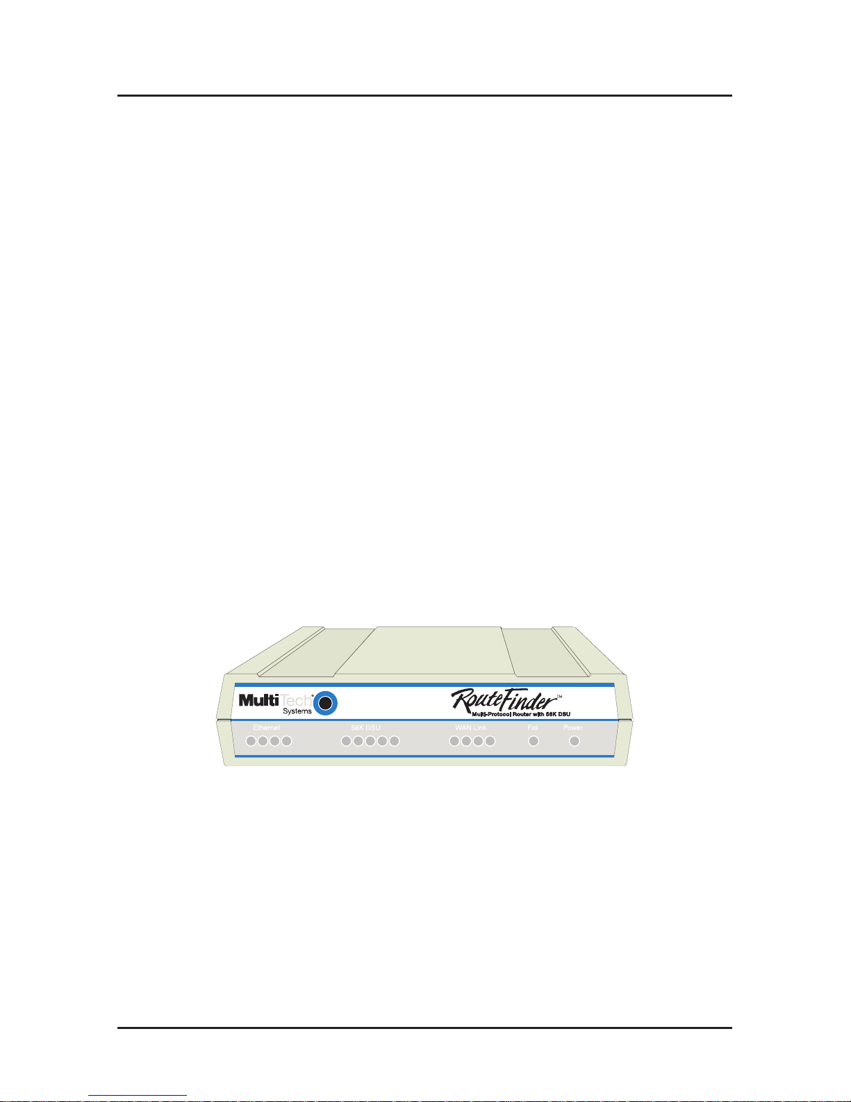
Introduction
Welcome to Multi-Tech's new DSU RouteFinder, Model
MTASR2-201, which provides secure and seamless LAN-toLAN routing capability and can also provide dial-up capability.
This unit supports multiple WAN services and supports a wide
range of routing protocols including IP, IPX, TCP, and RIP
version 2. When the WAN 2 port is configured to support it,
this unit also supports a secondary capability of dial-up
Remote Access Server (RAS) access for telecommuters and
mobile users from any Point-to-Point Protocol (PPP) or Serial
Line Internet Protocol (SLIP) networking client.
The DSU RouteFinder features a 10BaseT port for local LAN
connection, a command port for configuration, a 56K bps DDS
4-wire WAN connection, and an RS232/V.35 port for an
optional Data Communications Equipment (DCE) device (i.e.,
external modem, T1/E1 CSU/DSU, etc.). System management
is provided through the command port using bundled
Windows® based software which provides easy-to-use
configuration menus.
RD
TD
CL
LK
RD TD CD NS DS RD TD CD
V35
Figure 1. DSU RouteFinder
* Some DSU RouteFinder units may be marked “MultiRouter”
or “MultiRouter 200-Series”; they are equivalent to the “DSU
RouteFinder” referred to throughout this quick start guide.
Page 5

Introduction
5
Related Documentation
This DSU RouteFinder Quick Start Guide is intended to be
used by qualified systems administrators and network
managers. This quick start guide provides the necessary
information for a qualified person to unpack, cable, load
software, and configure the unit for proper operation.
A detailed DSU RouteFinder User Guide is also provided with
your unit. The user guide provides in-depth information on the
features and functionality of Multi-Tech’s DSU RouteFinder .
The User Guide is provided in disk form and is also available
from our web site.
The disk version is produced using Adobe Acrobat. To view or
print your copy of a user guide, load Adobe Acrobat Reader on
your system. Adobe Acrobat Reader can be downloaded from
Adobe’s W eb site at:
http://www .adobe.com/prodindex/acrobat/readstep.html
Launch the Reader and open the .pdf file that is on the disk.
Viewing and printing a user guide from the web also requires
that you have the Adobe Acrobat Reader loaded on your
system. The DSU RouteFinder User Guide is also available on
Multi-Tech’s Web site at:
http://www .multitech.com
From the MTS home page, click Support | Manuals | DSU
RouteFinder and choose DSU RouteFinder to download the
.pdf file.
Page 6
DSU RouteFinder Quick Start Guide
6
Safety Warnings
1. Never install telephone wiring during a lightning storm.
2. Never install telephone jacks in wet locations unless
the jack is specifically designed for wet locations.
3. Never touch uninsulated telephone wires or terminals unless
the telephone line has been disconnected at the network
interface.
4. Use caution when installing or modifying telephone lines.
5. Avoid using a telephone (other than a cordless type) during an
electrical storm. There may be a remote risk of electrical shock
from lightning.
6. Do not use the telephone to report a gas leak in the vicinity of
the leak.
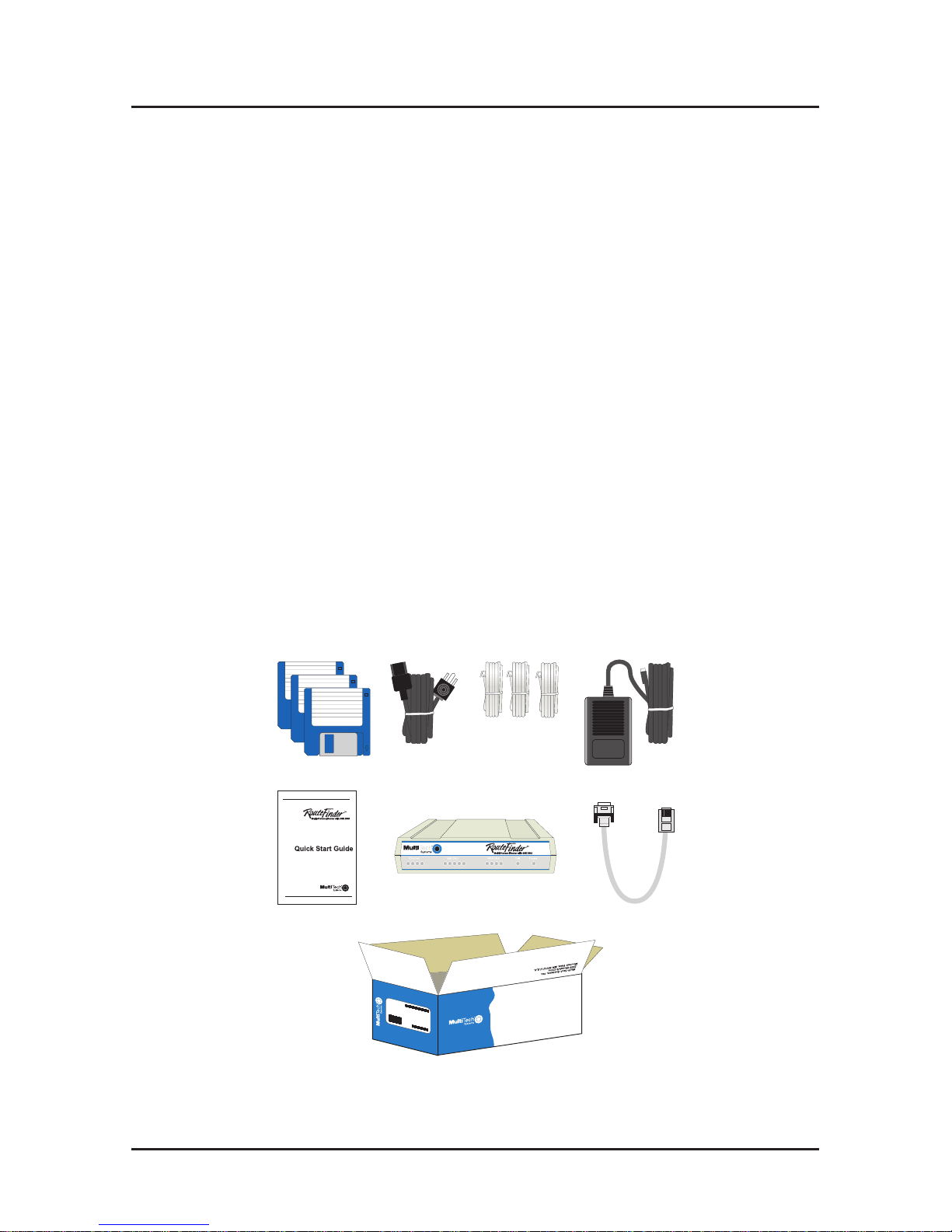
Unpacking your DSU RouteFinder
Remove all items from the box. See Figure 2.
MADE IN U.S.A
MADE IN U.S.A
RD
TD
CL
LK
RD TD CD NS DS RD TD CD
V35
Figure 2. Unpacking
Page 7
8-Position DIP Switch
7
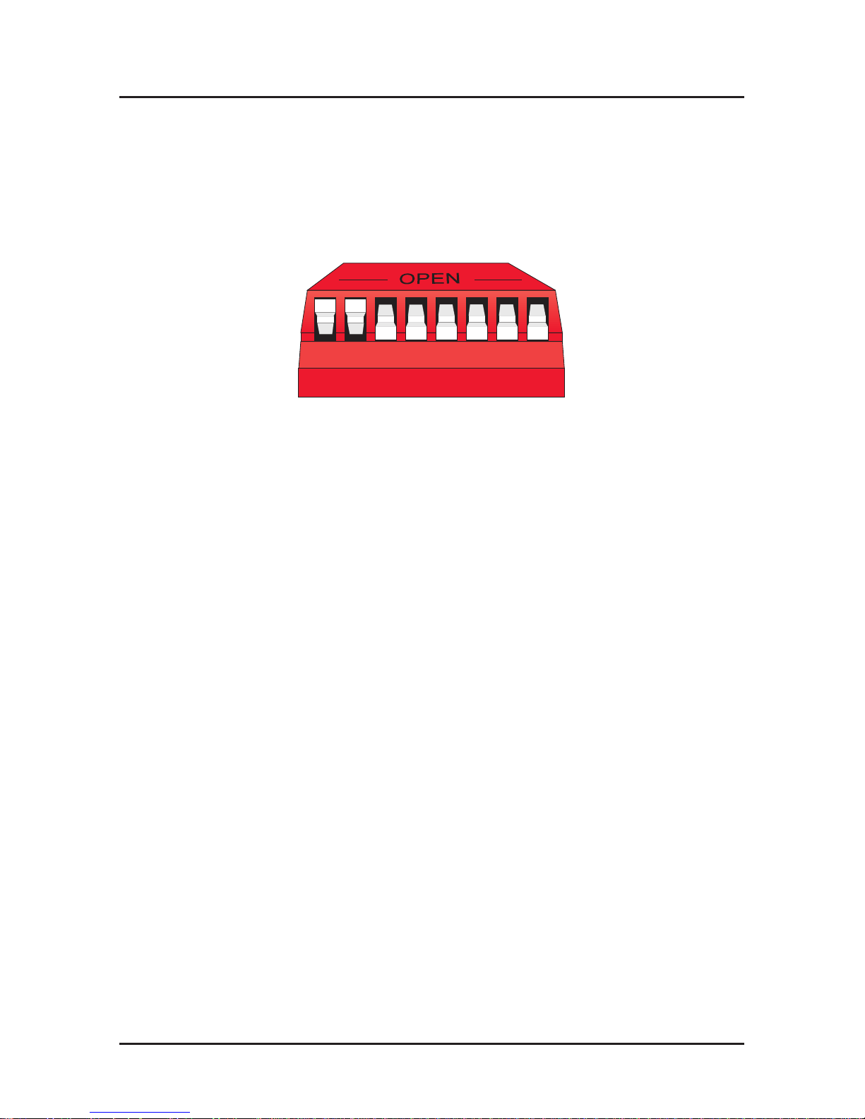
8-Position DIP Switch
The DSU RouteFinder is equipped with a 8-position DIP
switch. Figure 3 shows the DIP switch, and the chart that
follows details the default positions and other options.
56781234
Figure 3. 8-position DIP switch
Position 1: OPEN* (up) Normal Mode operation
Closed (down) Loopback Mode operation
Position 2: OPEN* (up) DDS clocking
Closed (down) Internal Clocking
Positions 3 - 8: Reserved for future use.
* Denotes Factory Default setting
Note: The DIP switch settings cannot be changed externally;
you must remove the circuit board from the chassis. Refer to
the steps in the next section, V.35 Shunt Procedure, for
instructions on removing the circuit board.
Page 8

DSU RouteFinder Quick Start Guide
8
V.35 Shunt Procedure
If you are using an external DCE device on the WAN 2 RS232/
V.35 port, and the connection will be a V.35 connection, the
internal shunt must be moved from the RS232C (default)
position prior to cabling and power-up. The following steps
detail the procedures for switching the shunt.
Step Procedure
1 Ensure that the external power supply is disconnected
from the DSU RouteFinder .
2 Turn the DSU RouteFinder over and remove the cabinet
mounting screw (Figure 4) from the chassis.
Front Panel
Back Panel
Cabinet Mounting Screw
Figure 4. Cabinet Mounting Screw Location
3 Being sure to support the back panel, turn the DSU
RouteFinder right side up, tilt the back panel down, and
slide the circuit board out of the chassis.
Page 9

V.35 Shunt Procedure
9
4 Place the unit on a flat, grounded surface.
5 Pry the shunt out of the RS232 position, and insert it in the
V.35 position. See Figure 5.
5
6
7
8
V.35 Shunt Position
RS232C Shunt Position
Back Panel Connectors
8-Position DIP Switch
RAM Sockets
LEDs
Figure 5. Shunt Positions
Note: if you wish to make changes to the 8-position DIP
switch, do so at this time. For details on DIP switch
settings, refer to the previous section, “8-Position DIP
Switch”.
6 Align the board with the guide slots on the inside of the
chassis and carefully slide the board back into the chassis.
7 While supporting the back panel, turn the DSU
RouteFinder over again, and replace the cabinet mounting
screw .
8 Turn the DSU RouteFinder right side up again and
proceed to the next section to connect the cables.
Page 10

DSU RouteFinder Quick Start Guide
10
Cabling your DSU RouteFinder
Cabling your DSU RouteFinder involves making the proper
Power , Command Port, and DSU connections, and optionally,
the RS232/V.35 connection. Figure 6 shows the back panel
connectors and associated cable connections. The procedure
that follows lists the steps for connecting the external cables to
your DSU RouteFinder .
Power Connection
PC Connection
10BASET COMMAND56K DSU POWER
ON
OFF
RS232/V.35
Ethernet Connection
DDS WAN Connection
To DCE
Device
Command Cable
Figure 6. Cable Connections
Page 11

Cabling
11
Cabling Procedure
Step Procedure
1. Connect one end of the power supply to a live AC outlet
and connect the other end to the DSU RouteFinder as
shown in Figure 6. The power connector is a 6-pin circular
DIN connector .
2. Connect the DSU RouteFinder to a PC using the RJ-45 to
DB-9 (female) cable provided with your unit. Plug the RJ45 end of the cable into the Command port of the DSU
RouteFinder and the other end into the PC’s COM port.
See Figure 6.
3. Connect a network cable to the ETHERNET 10BASET
connector on the back panel of the DSU RouteFinder.
Connect the other end of the cable to your network.
4. Connect one end of an RJ-45 cable to the 56K DSU
connector on the back of the DSU RouteFinder . Connect
the other end to your Digital Data Service (DDS) WAN
connection.
5. If you plan to use the optional RS232 port for dial backup,
connect one end of an RS232 cable to the RS232/V.35
connector on the back panel of the DSU RouteFinder and
connect the other end of the cable to an external DCE
device such as a modem or T1/E1 CSU/DSU.
6. Turn on power to the DSU RouteFinder by setting the ON/
OFF switch to the ON position. Wait for the FAIL LED on
the DSU RouteFinder to go OFF before proceeding. This
may take a couple of minutes to go OFF.
At this time your DSU RouteFinder is completely cabled.
Proceed to the next section to load the RouteFinder software.
Page 12

DSU RouteFinder Quick Start Guide
12
Loading your Software
The following loading procedure does not provide every screen or
option in the process of installing the RouteFinder software. It is
assumed that a technical person with a thorough knowledge of
Windows and the software loading process is doing the
installation.
1. Run Windows on the PC that is connected to the DSU
RouteFinder’s Command Port.
2. Insert the RouteFinder Disk 1 into the disk drive on the PC that
is connected to the DSU RouteFinder .
3. Win3.1 users - in the Program Manager, access Run by
clicking File | Run. In the Run dialog box, type a:\setup.exe or
b:\setup.exe (depending on the letter of your floppy disk drive)
in the Command Line field and then click OK.
Win95/98/NT users - click Start | Run. In the Run dialog box
click on the down arrow and choose a:\setup or b:\setup
(depending on the letter of your floppy disk drive), then click
OK.
Page 13

Software
13
4. When the Welcome screen appears, press Enter or click
Next> to continue.
5. Press Enter or click Next> to continue.
6. When the Select Program Folder dialog box appears, click
(to the right of the text) on the Program Folders text box, then
backspace through “| RASFinder” until the cursor is next to the
letter “r” in “RouteFinder”; this will become the name of the icon
group. Press Enter or click Next> to continue.
Page 14

DSU RouteFinder Quick Start Guide
14
7. The next dialog box enables you to designate the COM port of
the PC that is connected to the DSU RouteFinder. On the
Select Port field, click on the down arrow and choose the
COM port of your PC (COM1 -- COM4) that is connected to the
DSU RouteFinder .
8. Click OK to continue.
9. Click Finish to continue. The “Do you want to perform
upgrade?” dialog box is displayed.
Page 15

Software
15
10. Click No to skip the upgrade process. The “Do you want to
download default setup?” dialog box appears.
11. Click Yes to download the default setup. (Clicking on No
prevents you from setting up the defaults and downloading
them to the DSU RouteFinder; instead, you are returned to the
program manager , where in Windows 95 you will see a window
with shortcut icons for all the various utility programs in the
software.)
12. The Novell IPX Protocol Default Setup dialog box appears.
Note: To configure your DSU RouteFinder , you now will use a
series of dialog boxes -- Novell IPX Protocol Default Setup,
IP Protocol Default Setup, and WAN Ports Default Setup.
13. If your network protocol is IPX, continue with the following
steps. However , if your network protocol is IP, click on the IPX
Routing Enable check box to
disable
IPX, then click OK and
proceed to step 18.
Page 16

DSU RouteFinder Quick Start Guide
16
14. Router Name: If this is the only DSU RouteFinder on your
network, you can use the default Router Name (MTROUTER);
otherwise, you must assign a new Router Name in this field.
The Router Name can be any printable ASCII string of up to 47
characters. The DSU RouteFinder uses this name to advertise
its service in the IPX internetwork.
15. Ethernet: You can enable Auto Learn Ethernet Network
Numbers by leaving the default (Yes) checked, or you can
manually assign the network numbers after disabling the Auto
Learn option by clicking on No. If no file server is connected to
the Ethernet segment, then you should select No.
If you leave Auto Learn enabled, the DSU RouteFinder will
learn the IPX network numbers from the file server.
If you disable Auto Learn, record in the space below the
network numbers assigned by the network file server for each
of the four frame types [(Raw (802.3), LLC (802.2), EthernetII
(T ype II), SNAP]. You can also record here the Network
numbers for WAN 1 and WAN 2.
RAW (802.3) Frames Network Number _____________
LLC (802.2) Frames Network Number ______________
TYPE_II Frames Network Number _________________
SNAP Frames Network Number ___________________
W AN 1 Network Number _________________________
W AN 2 Network Number _________________________
When you manually assign network numbers, make sure they
match the network numbers assigned to your local file server
(if any).
Page 17

Software
17
16. WAN1 and WAN 2: Click the associated check box if one or
the other is to be disabled; otherwise, leave the Enable
checked and double-click the Network number text box and
enter the WAN Network number.
The WAN network numbers have to be assigned by the
network administrator and must be unique throughout the
entire internetwork.
Note: The WAN ports do not have the capability of learning
the network number , unlike the LAN port (i.e., the WAN ports
do not have a file server).
17. Click OK when you are satisfied with your selections.
18. If you clicked OK from the Novell IPX Protocol Default Setup
dialog box (step 13), the IP Protocol Default Setup dialog box
is displayed.
19. To change the IP parameters, proceed to the next step.
Otherwise, click OK to open the W AN Ports Default Setup
dialog box, then proceed to step 23.
20. The default Ethernet IP Address has to be changed to your
unique LAN address. In the Ethernet group, change the default
IP Address, Subnet Mask, and Frame T ype to the values
assigned to your LAN port.
21. Click OK when you are satisfied with your selections.
22. The WAN Ports Default Setup dialog box appears with both
WAN Ports enabled. Note: the External/Internal Clock for WAN
Page 18

DSU RouteFinder Quick Start Guide
18
1 is selected on the 8-position DIP switch on the circuit board
(External or DDS Clocking is the default). If WAN 1 is not on a
Direct Connection or Leased Line, click that option to disable it,
then enter your ISP’s phone number in the Dial Number field.
23. Set up all parameters in the WAN 2 group. Select the modem
type from the pull-down list; for a synchronous connection,
click the Asynchronous option to disable it; for dial-out
operation, enter the (ISP) phone number in the Dial Number
field, or click the Answering option if WAN 2 will be used to
answer dial-in calls from remote locations.
24. Click OK when you are satisfied with your selections.
25. The Checking Router dialog box is displayed. Click OK.
Page 19

Software
19
The Writing Setup dialog box (with the current date and the
file size in bytes) is displayed as the software sends the
configuration file to the DSU RouteFinder .
The Rebooting dialog box is displayed.
26. Check to ensure that the Fail LED on the DSU RouteFinder
goes Off after the download is complete and the DSU
RouteFinder is rebooted (the Rebooting dialog box goes
away).
27. Win3.1 users - you are returned to your Program Manager
where the RouteFinder Program Group and Program Items
(RouteFinder icons) have been created.
Win95/98/NT users - you are returned to your desktop.
Your DSU RouteFinder is operational at this time.
Page 20

DSU RouteFinder Quick Start Guide
20
Limited Warranty
Multi-Tech Systems, Inc. (“MTS”) warrants that its products will be
free from defects in material or workmanship for a period of two
years from the date of purchase, or if proof of purchase is not
provided, two years from date of shipment. MTS MAKES NO
OTHER WARRANTY, EXPRESSED OR IMPLIED, AND ALL
IMPLIED WARRANTIES OF MERCHANTABILITY AND FITNESS
FOR A PAR TICULAR PURPOSE ARE HEREBY DISCLAIMED.
This warranty does not apply to any products which have been
damaged by lightning storms, water , or power surges or which
have been neglected, altered, abused, used for a purpose other
than the one for which they were manufactured, repaired by the
customer or any party without MTS’s written authorization, or used
in any manner inconsistent with MTS’s instructions.
MTS’s entire obligation under this warranty shall be limited (at
MTS’s option) to repair or replacement of any products which
prove to be defective within the warranty period, or , at MTS’ s
option, issuance of a refund of the purchase price. Defective
products must be returned by Customer to MTS’s factory
transportation prepaid.
MTS WILL NOT BE LIABLE FOR CONSEQUENTIAL DAMAGES
AND UNDER NO CIRCUMSTANCES WILL ITS LIABILITY
EXCEED THE PURCHASE PRICE FOR DEFECTIVE
PRODUCTS.
Page 21

Warranty, Service and Regulatory Information
21
Service
Multi-Tech has an excellent staff of technical support personnel
available to help you get the most out of your Multi-Tech product.
Refer to your DSU RouteFinder User Guide for Warranty and
Service information.
FCC Declaration
NOTE: This equipment has been tested and found to comply with
the limits for a Class A digital device, pursuant to Part 15 of the
FCC Rules. These limits are designed to provide reasonable
protection against harmful interference when the equipment is
operated in a commercial environment. This equipment generates,
uses and can radiate radio frequency energy, and if not installed
and used in accordance with the instructions, may cause harmful
interference to radio communications. Operation of this equipment
in a residential area is likely to cause harmful interference in which
case the user will be required to correct the interference at his own
expense.
Warning: Changes or modifications to this unit not expressly
approved by the party responsible for compliance could void the
user’s authority to operate the equipment.
Page 22

82087301
 Loading...