

Page 1

LAN-to-LAN Routing
for Central-Site and
Branch Office Networks
Model MTASR1-100
Quick Start Guide
Page 2

Quick Start Guide
82087200 Revision A
RouteFinder (Model MTASR1-100)
This publication may not be reproduced, in whole or in part, without
prior expressed written permission from Multi-Tech Systems, Inc. All
rights reserved.
Copyright © 1998, by Multi-Tech Systems, Inc.
Multi-Tech Systems, Inc. makes no representations or warranties
with respect to the contents hereof and specifically disclaims any
implied warranties of merchantability or fitness for any particular
purpose. Furthermore, Multi-Tech Systems, Inc. reserves the right
to revise this publication and to make changes from time to time in
the content hereof without obligation of Multi-Tech Systems, Inc. to
notify any person or organization of such revisions or changes.
Record of Revisions
Revision Description
A Manual released; covers software version 3.00.
11/3/98) All pages at revision A.
Patents
This Product is covered by one or more of the following U.S.
Patent Numbers:
5.301.274; 5.309.562; 5.355.365; 5.355.653;
5.452.289; 5.453.986
. Other Patents Pending.
TRADEMARK
Trademark of Multi-Tech Systems, Inc. is the Multi-Tech logo.
RouteFinder is a trademark of Multi-Tech Systems, Inc.
Windows is a registered trademark of Microsoft in the U.S. and
other countries.
Adobe and Acrobat are trademarks of Adobe Systems, Inc.
Multi-Tech Systems, Inc.
2205 Woodale Drive
Mounds View, Minnesota 55112
(612) 785-3500 or (800) 328-9717
Fax 612-785-9874
Tech Support (800) 972-2439
BBS (612) 785-3702 or (800) 392-2432
Internet Address: http://www.multitech.com
Fax-Back (612) 717-5888
Page 3

iii
Contents
Introduction.................................................................................... 4
Related Documentation ................................................................. 5
Unpacking Y our RouteFinder......................................................... 6
Cabling your RouteFinder.............................................................. 7
Changing Shunt Position ............................................................... 9
RouteFinder Software...................................................................1 1
Loading your Software.................................................................11
Setting Up Your Remote User Database ..................................... 19
Setting Up the Dial-up Networking............................................... 23
Loading Dial-Up Network Software.............................................. 33
Loading Your Protocol ................................................................. 35
Loading Client for Microsoft Networks ......................................... 37
Installing Y our Modem ................................................................. 39
Limited Warranty ......................................................................... 40
Service ........................................................................................ 40
European Community Directives ................................................. 41
Page 4
RouteFinder MTASR1-100 Quick Start Guide
4
Introduction
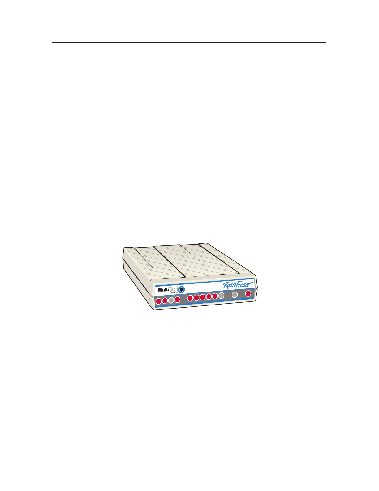
Welcome to Multi-Tech's new RouteFinder™, model MTASR1-100,
an IP/IPX router for interconnecting LANs using switched or
dedicated wide area telecommunications links. The MTASR1-100
provides IP and IPX routing and Media Access Control (MAC)
layer bridging for all other protocols over its WAN ports. It features
a 10Base-T or AUI port for local LAN connection, Command Port
for configuration, and an RS232/V.35 port for asynchronous or
synchronous remote WAN connection using standard point-topoint protocol (PPP). The configurable W AN port operates with a
compatible communication device operating at up to 1 15 Kbps
(async) or T1 (sync) speeds. These devices include asynchronous
and synchronous modems, ISDN terminal adapters and DDS,
Switched 56, Fractional T1, and T1 DSUs. System management is
provided through the command port using bundles Windows
software that provides easy-to-use configuration menus.
Figure 1. RouteFinder MTASR1-100
Page 5

Introduction
Related Documentation
This MTASR1-100 Quick Start Guide is intended to be used by
qualified systems administrators and network managers. This
quick start provides the necessary information for a qualified
person to unpack, cable, load software, and configure the unit for
proper operation.
A detailed User Guide is also provided with your unit. This user
guide provides in-depth information on the features and functionality of Multi-Tech’s family of RouteFinders and RASFinders. The
User Guide is provided in diskette form and is also available from
our Web site.
The diskette media is produced using Adobe Acrobat for viewing
and printing the user guide. To view or print your copy of the user
guide, load Adobe Acrobat Reader on your system. Adobe Acrobat
Reader can be downloaded from Adobe’ s Web site at:
http://www.adobe.com/prodindex/acrobat/roadstep.html
Launch the Reader and select the .pdf file from the diskette.
Viewing and printing a user guide from the web also requires that
you have the Adobe Acrobat Reader loaded on your system. The
User Guide is also available on Multi-Tech’s Web site at:
http://www.multitech.com
From the MTS home page, click Support | Manuals |
RouteFinder and choose the User Guide which will download the
.pdf file.
5
Page 6

RouteFinder MTASR1-100 Quick Start Guide
Unpacking Your RouteFinder
Remove all items from the box. See Figure 2.
MADE IN U.S.A
MADE IN U.S.A
Figure 2. Unpacking
6
Page 7
Cabling
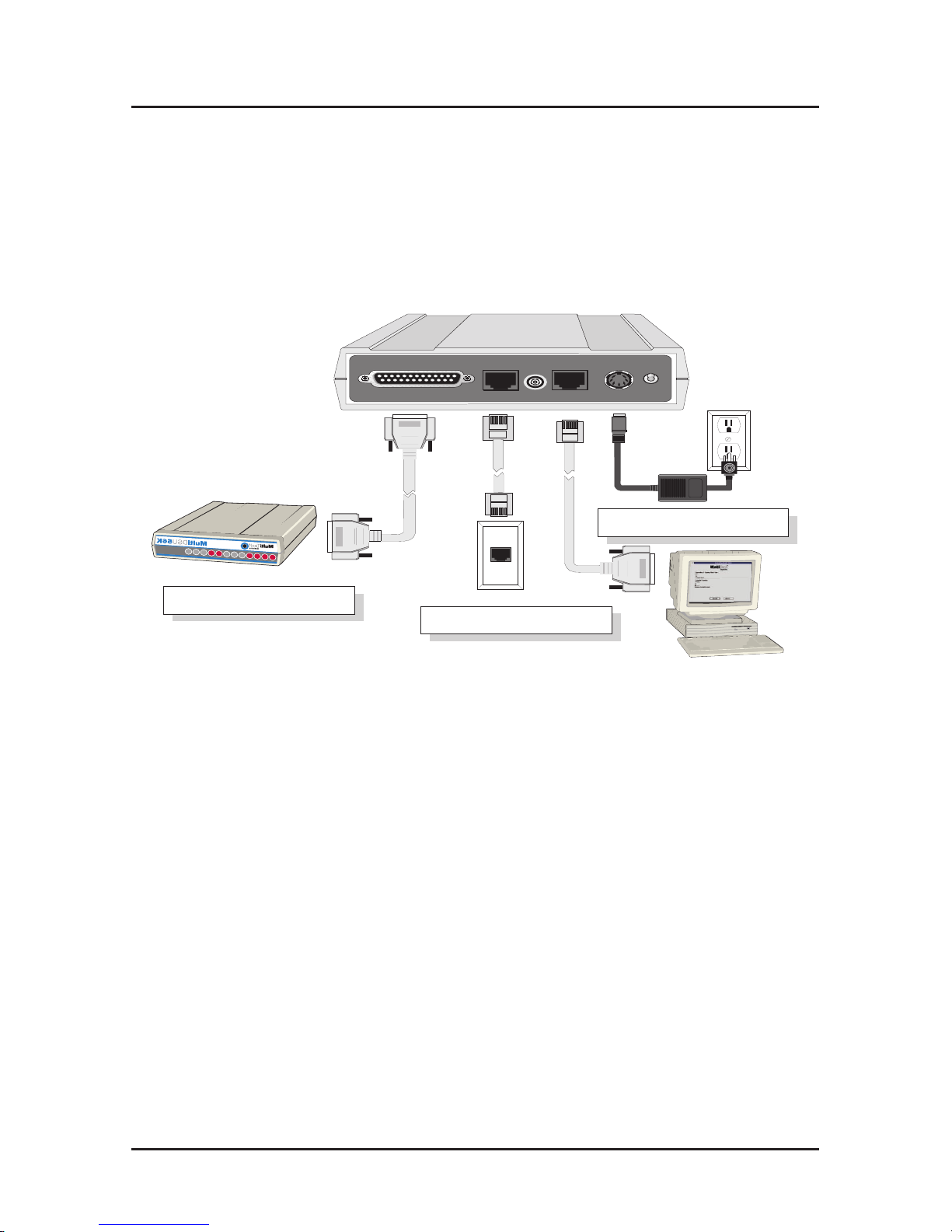
Cabling your RouteFinder
Cabling your RouteFinder involves making the proper WAN,
Ethernet, Command Port and power connections. Figure 3 shows
the back panel connectors and the associated cable connections.
Table 1 details the procedures for connecting the cables to your
RouteFinder .
10BASE T
OFF
RS232/V.35
POWER
COMMAND PORT
ON
10BASE 2
Ethernet Connection
Power Connection
WAN Connection
Figure 3. Cable Connections
7
Page 8

RouteFinder MTASR1-100 Quick Start Guide
8
Table 1. Cabling Procedure
Step Procedure
1. If the WAN link needs to be changed to a V.35 interface,
perform the procedure in Table 2.
2. Connect the RouteFinder Command Port to your PC using
the short RJ-45 to DB25 (female) cable provided with your
unit.
Plug the RJ-45 end of the cable into the Command Port on
the RouteFinder . Plug the other end into a COM port on
the PC. See Figure 3.
3. Connect an RJ-45 (UTP) cable to the 10BaseT connector
on the back panel or a BNC (thin coaxial cable) connector
to the 10Base2 connector .
4. Connect an RS232C/D or V.35 interface cable to the back
panel RS232/V.35 connector as shown in Figure 3.
Connect the other end of the cable to the appropriate
connector on the external link device.
5. Connect one end of the power supply to a live AC outlet,
then connect the other end to the POWER connector on
the RouteFinder as shown in Figure 3. The power
connector is a 6-pin circular DIN connector .
6. Turn on power to the RouteFinder by setting the ON/OFF
switch on the back panel to the ON position.
At this time your RouteFinder is completely cabled and
powered On. Proceed to the next section to load the
RouteFinder software.
Page 9
Cabling
Changing Shunt Position
Table 2 provides the procedure for moving the WAN link shunt
when the RouteFinder is being connected to an external composite
link device with a V.35 interface.
Table 2. V.35 Shunt Procedure
Step Procedure
1. Ensure that the external power supply is disconnected
from the RouteFinder .
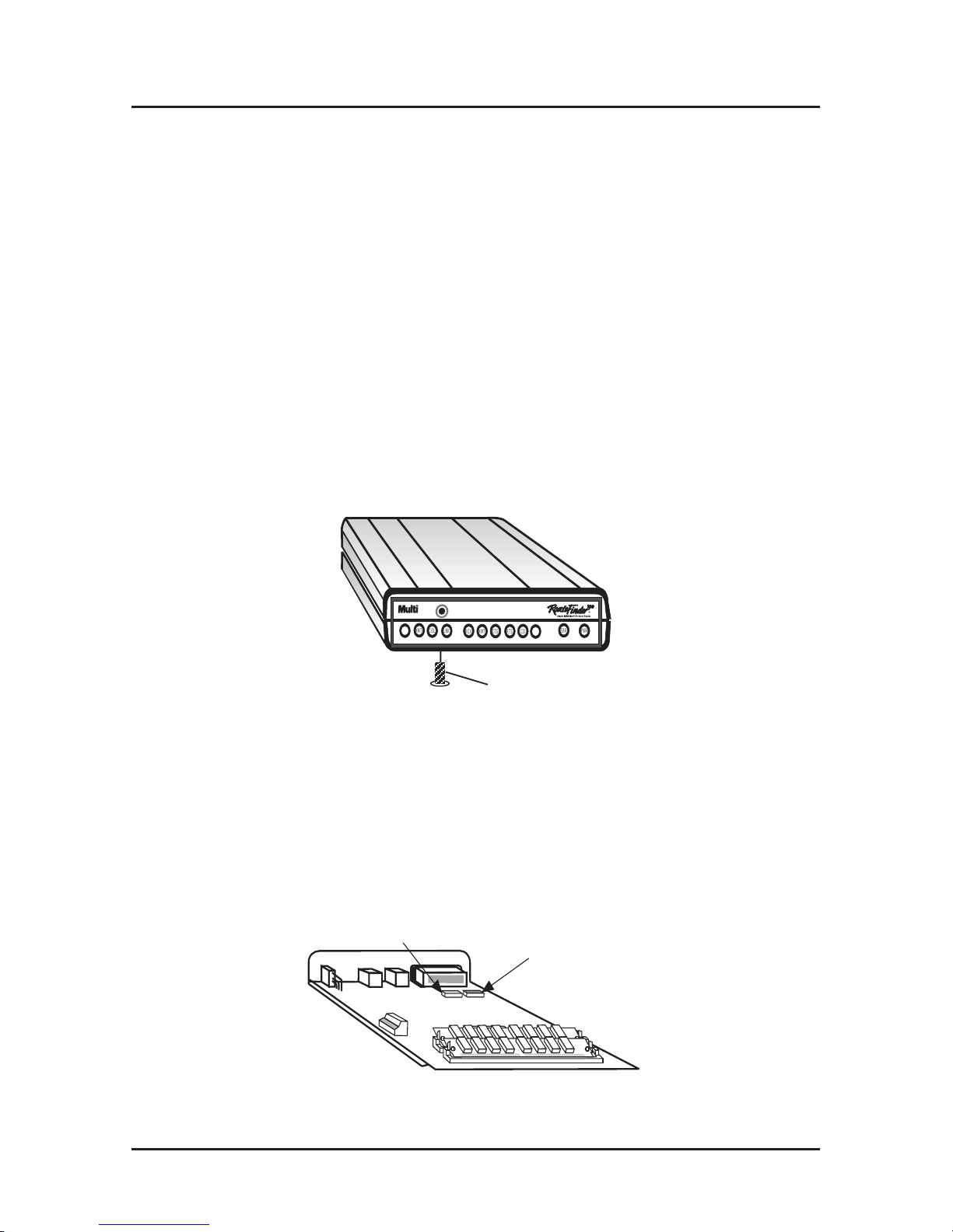
2. Turn the unit upside down and remove the cabinet
mounting screw at the center back of the cabinet. See
Figure 4.
Cabinet
Mounting
Screw
®
ETHERNET FAIL
POWER
RCV
XMT
COL
LNK
RCV
XMT
CTS
RTS
ERR
PWR
Tec
h
Systems
WAN LINK
CD
V35
Figure 4. Cabinet Mounting Screw
3. Turn the unit right side up, then slide the base out the rear
of the cabinet.
4. Position the base so the front panel LEDs are toward you,
as in Figure 5.
RS232
Shunt Position
V.35
Shunt Position
Figure 5. V.35 Shunt
9
Page 10
RouteFinder MTASR1-100 Quick Start Guide
5. Pry the shunt out of the default RS232 position, then insert
the shunt in the V.35 position for the WAN link. See Figure
5.
6. Slide the base back into the cabinet with the LEDs going
toward the front and the back side grounding tabs pressing
against the side of the cabinet.
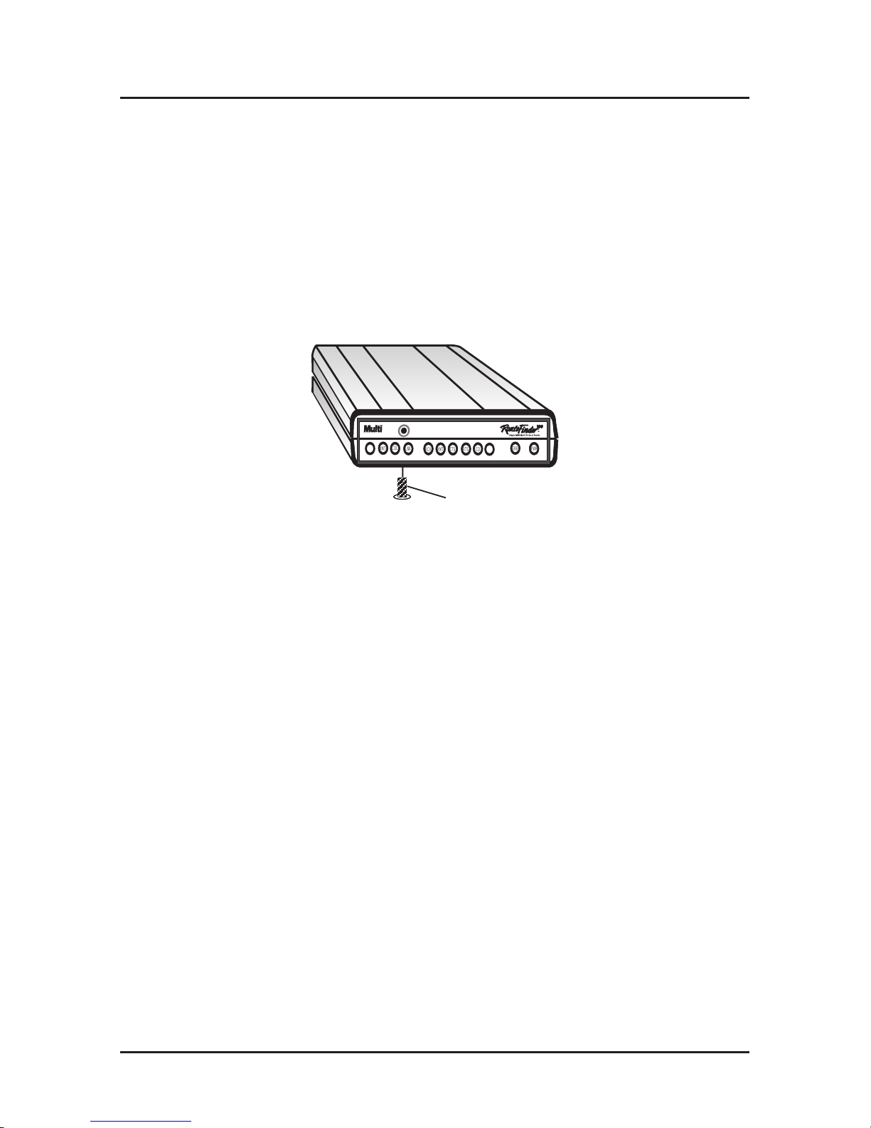
7. Turn the unit upside down and replace the cabinet
mounting screw that was removed in step 2. See Figure 6.
Cabinet
Mounting
Screw
®
ETHERNET FAIL
POWER
RCV
XMT
COL
LNK
RCV
XMT
CTS
RTS
ERR
PWR
Tec
h
Systems
WAN LINK
CD
V35
Figure 6. Replacing Cabinet Mounting Screw
8. Turn the unit right side up and return to Table 1 to connect
the cables.
10
Page 11
Software
RouteFinder Software
The following software loading procedure does not provide
every screen or option. It is assumed that a technical person
with a thorough knowledge of Windows and the software
loading process is doing the installation.
Loading your Software
1. Run Windows on the PC that is connected to the
RouteFinder’s Command Port.
2. Insert the RouteFinder 3.00 Disk 1 into the disk drive on
the PC that is connected to the RouteFinder .
3. Win3.1 users - access Run by clicking the File menu in
the Program Manager, then click Run. In the Run dialog
box, type a:\setup.exe or b:\setup.exe (depending on the
letter of your floppy disk drive) in the Command Line field
and then click OK.
Win95/NT users - click the Start button, then click Run. In
the Run dialog box click the down arrow and choose
a:\setup or b:\setup (depending on the letter of your
floppy disk drive), then click OK.
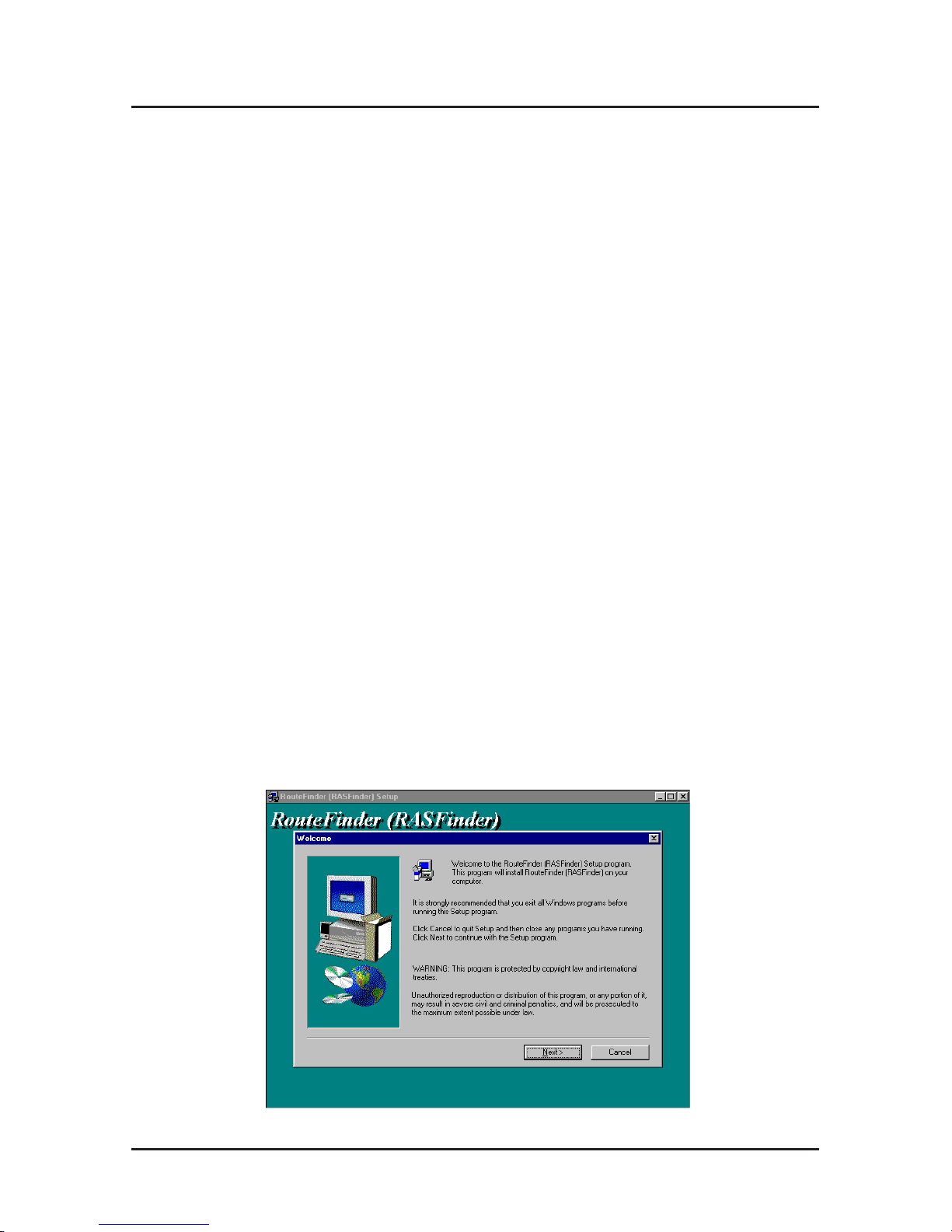
4. The Welcome screen is displayed.
Press Enter or click Next> to continue.
11
Page 12
RouteFinder MTASR1-100 Quick Start Guide
12
5. Follow the on-screen instructions to install your
RouteFinder software.
Press Enter or click Next> to continue.
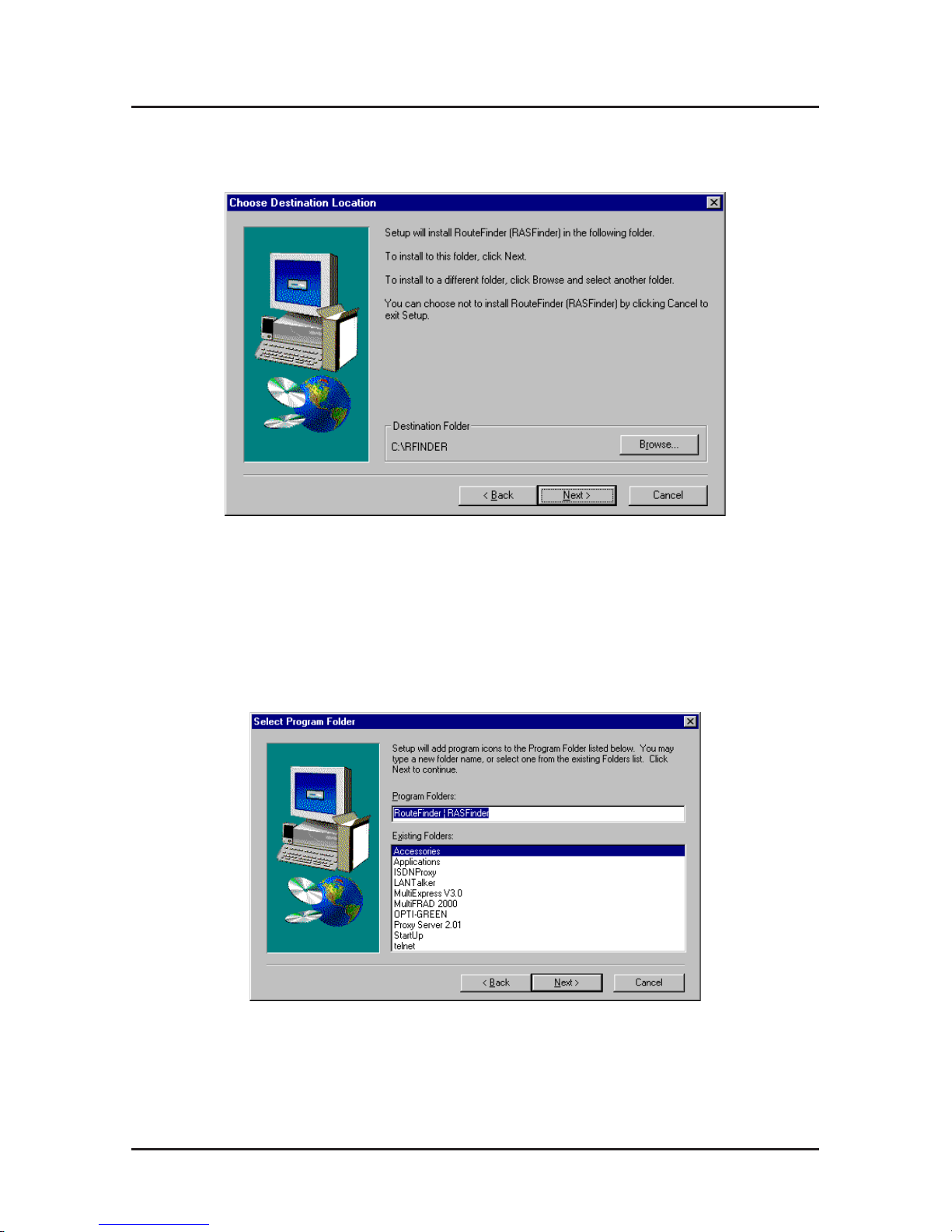
6. When the Select Program Folder dialog box appears,
double-click the word “RASFinder” and delete it (and
preceding spaces, etc.) leaving the word “RouteFinder” in
the text box; this will become the name of the icon group.
Press Enter or click Next> to continue.
7. The next dialog box enables you to designate the COM
port of the PC that is connected to the RouteFinder . On
the Select Port field, click the down arrow and choose the
COM port of your PC (COM1 -- COM4) that is connected
to the RouteFinder .
Page 13

Software
Click OK to continue.
8. The Setup Complete dialog box is displayed. Click the
Finish button to continue.
9. The following message is displayed.
Click No to skip the upgrade process.
13
Page 14

RouteFinder MTASR1-100 Quick Start Guide
14
10. The following message is displayed.
Click Y es to download the default setup you’ve just
defined. Clicking No prevents the defaults from being
downloaded to the RouteFinder .
11. The following dialog box is displayed.
Click Yes to continue
12. The Novell IPX Protocol Default Setup dialog box
appears.
Note: To configure your RouteFinder, you will use a series
of dialog boxes, including IPX Protocol Default Setup, IP
Protocol Default Setup, and WAN Ports Default Setup.
13. If your network protocol is IPX, continue with the following
steps. However , if your network protocol is IP, click the IPX
Page 15

Software
Routing Enable check box to
disable
IPX, then click OK
and proceed to step 18.
14. Router Name: If this is the only RouteFinder on your
network, you can use the default Router Name
(MTROUTER); otherwise, you must assign a new Router
Name in this field. The Router Name can be any printable
ASCII string of up to 47 characters. The RouteFinder uses
this name to advertise its service in the IPX internetwork.
15. Ethernet: You can enable Auto Learn Ethernet Network
Numbers by leaving the default (Yes) selected, or you can
disable the Auto Learn option by selecting No and then
manually assign the network numbers. If no file server is
connected to the Ethernet segment, disable this option
and manually assign the network numbers.
If Auto Learn is enabled, the RouteFinder will learn the IPX
network numbers from the file server .
If you disable Auto Learn, record the network numbers
assigned by the network file server for each of the four
frame types [(Raw (802.3), LLC (802.2), EthernetII (T ype
II), SNAP] in the space provided below .
RAW (802.3) Frames Network Number _____________
LLC (802.2) Frames Network Number ______________
TYPE_II Frames Network Number _________________
SNAP Frames Network Number ___________________
W AN 1 Network Number _________________________
When you manually assign network numbers, make sure
they match the network numbers assigned to your local
file server (if any).
16. WAN: Enter the WAN network number for the WAN Port
by clicking the Network Number field, backspacing through
the default number , and entering your new WAN number.
Also, the WAN network number must be the same as the
RouteFinder on the other end of a LAN-to-LAN link.
15
Page 16

RouteFinder MTASR1-100 Quick Start Guide
16
The WAN network number has to be assigned by the
network administrator and must be unique throughout the
entire internetwork.
Note: The W AN port does not have the capability of
learning the network number , unlike the LAN port (i.e., the
WAN port does not have a file server).
17. Click OK when you are satisfied with your selections.
18. If you disabled IPX and then clicked OK from the IPX
Protocol Setup dialog box (step 13), the IP Protocol
Default Setup dialog box is displayed.
19. To change the IP parameters, proceed to the next step.
Otherwise, click OK to display the WAN Ports Default
Setup screen and proceed to step 24.
20. The default Ethernet IP Address has to be changed to your
unique LAN address. Therefore, start by assigning an
acceptable unique IP address to the Ethernet port.
21. Change the default Subnet Mask and Frame Type to the
values you have assigned to your LAN port.
22. The default WAN Address has to be changed to your
unique WAN address. Assign an acceptable unique WAN
port address in the Address field.
23. Change the default IP Mask and Remote Address for the
WAN port to the value you have assigned to your WAN.
Click OK when you are satisfied with all your selections.
24. The WAN Ports Default Setup screen is displayed.
Page 17

Software
25. If the WAN port is connected to a synchronous device,
select Synchronous; the default uses an external clock in
the synchronous device. If you are using the
RouteFinder’s internal clock, select Internal Clock and
select the appropriate Clock Speed from the pull-down
list.
If the WAN port is connected to an asynchronous device,
click Asynchronous, then click the Direct Connect/
Leased Line option to disable it; the Modem T ype and
Dial Number fields become active. Select your external
modem from the pull-down list. The Speed can either be
left at the default 115200 value or set to the maximum
capability of your modem.
If the WAN port is being set up to make a call, enter the
phone number to be dialed in the Dial Number field.
If the WAN port is being set up to answer a call, click the
Answering option (the Dial Number field becomes
inactive).
26. Click OK when you are satisfied with your selections.
Note: If necessary, the WAN port can be configured
further , after completion of software installation, by clicking
Router Configuration and then clicking the WAN button on
the Router Setup screen.
27. The Checking Router dialog box is displayed.
17
Page 18

RouteFinder MTASR1-100 Quick Start Guide
18
Click OK to proceed.
28. The Writing Setup dialog box is displayed as the setup
configuration is written to the RouteFinder .
After the setup is written to the RouteFinder , the unit is
rebooted.
29. Check to ensure that the FAIL LED on the RouteFinder is
Off after the download is complete. This may take several
minutes as the RouteFinder reboots.
30. Win3.1 users - you are returned to your Program
Manager where the RouteFinder Program Group and
Program Items (Windows icons) have been created.
Win95/NT users - you are returned to your desktop.
Your RouteFinder is operational at this time.
Page 19

User Data Base
Setting Up Your Remote User Database
The remote user database lets you gather information about your
remote users. You can add remote users, remove users from the
database, or you can edit information in the database.
1. Win3.1 users - From the Program Manager , click the
Remote User Data Base icon.
Win95 users - From your desktop, click the Start button,
point to Programs, then RouteFinder, and then click
Remote User Data Base.
2. The Users List dialog box is displayed.
19
Page 20

RouteFinder MTASR1-100 Quick Start Guide
Click the Add button.
3. The Add Users dialog box is displayed.
20
Page 21

Dial-Up Network
4. Build your user database by filling in the following fields for
each user .
User Name.
The User Name can have as many as 39 characters. All
printable characters are permitted; however , no blanks
are allowed in the user name. In dial-in and dial-out
applications, the user name is treated as a case
insensitive string.
User Password.
The User Password can have up to 7 characters. In places
where the password is used as a character string, it is
treated as a case insensitive string. Elsewhere (PPP’s
CHAP), it is treated as a case sensitive pattern.
Call Back
You have to click this check box (or press Alt-B) to check
this box and access the following three Call Back
functions.
Call Back Security Enabled
This parameter is used in dial-in applications where the
user is required to be called back at a specific number .
Enabling this parameter (by Alt-S) results in having the
administrator assign the call back parameters. Leave this
function disabled if the user is permitted to choose the call
back number and the call back delay.
Call Back Number
The callback number is editable only if callback security is
enabled (checked). This is the number where the user will
be called back. When a specific number is listed here, the
user cannot choose the number where he wants to be
called back.
21
Page 22

RouteFinder MTASR1-100 Quick Start Guide
Call Back Delay
Call back delay is editable only if callback security is
enabled. This specifies the duration (in seconds) after
which the user will be called back at the administratorassigned Call Back Number .
Protocols
This lets you select the protocol(s) this user can use to dial
into the RouteFinder .
Dial In Port
Only WAN Port1 is available for dialing into the
RouteFinder .
Dial Out Port
Only WAN Port1 is available for dialing out from the
RouteFinder .
5. After each user is defined on the Add Users screen, click
the OK button to display the updated Users List dialog
box. Click the Add button to continue adding users to your
database.
6. When you have added all your users to the database, click
the Download button (at the bottom of the Users List
dialog box) to load the database into the RouteFinder .
22
Page 23

Dial-Up Network
Setting Up the Dial-up Networking
Setting up a dial-up network involves checking for hardware
components and if the necessary software is loaded and
configured properly. The setting up a dial-up network procedure
looks at what software is loaded and if it is not loaded, a separate
procedure is provided so that you can continue down a single path
to the point of making a call on your network. Separate procedures
are provided for loading the dial-up network software, TCP/IP, and
the client for Microsoft networks.
1. Check if the Dial-up Networking software is installed.
Double-click the My Computer icon. You should see an
icon labeled Dial-up Networking in the My Computer
window .
If you do not find a Dial-Up Networking icon in My
Computer , you need to load it; refer to the Loading Dial-
up Networking Software procedure in this section.
2. V erify that your Protocol is installed. Double-click the
Control Panel icon. In the Control Panel window , doubleclick the Network icon. A Network Configuration window
will appear .
23
Page 24

RouteFinder MTASR1-100 Quick Start Guide
24
A list of items will appear in a panel under the label The
following network components are installed:.
3. If your network protocol is installed, continue with the
next step, Select the Primary Network Logon.
If your network protocol is not installed, refer to
Loading your Protocol procedure in this section.
After installing the protocol, reboot your computer . Your
computer may ask you if you want to restart it now . Click
the Yes button.
4. Select the Primary Network Logon. In the Primary
Network Logon drop-down list, select your network client.
5. Exit the software. Click the OK button at the bottom of the
window .
Page 25

Dial-Up Network
6. Install your modem. If you are using a new modem and
have NOT installed it already, you will need to install it
now , refer to the Installing Your Modem procedure in this
section.
7. Create a Dial-up connection icon for the RouteFinder .
Open the Dial-up Networking software. Double-Click the
Dial-up Networking icon in the My Computer window .
8. Select Make New Connection. Double-click the Make
New Connection icon.
9. Name the new connection. In the box labeled Type a
name for the computer you are dialing, enter the name
of your RouteFinder . The network administrator should
provide you with the RouteFinder name.
25
Page 26

RouteFinder MTASR1-100 Quick Start Guide
26
10. Continue to the next window. Click the Next> button at the
bottom of the window .
11. In the Telephone number box, enter your RouteFinder’s
telephone number . Do NOT enter the area code in the
"Area code" box unless the call is a long-distance call for
you.
12. Continue to the next window. Click the Next> button at the
bottom of the window .
13. Exit the window. Click the Finished button at the bottom of
the window . You should now see a new Dial-up icon
labeled with the name you gave your RouteFinder .
Page 27

Dial-Up Network
14. Configure your new RouteFinder Dial-up icon.
Click your RouteFinder icon that you just created. Click the
file menu button at the top of the Dial-up Networking
window , then select the Properties option. A new window
will appear .
16. Select Server types. Click the Server Types button. A
window will appear .
27
Page 28

RouteFinder MTASR1-100 Quick Start Guide
16. Select server type. Near the top of the window you will see
a Type of Dial-Up Server drop-down list. Select the "PPP:
Windows 95, Windows NT 3.5, Internet" option.
17. Ensure that all Advanced Options: are not checked.
18. Select your network protocol from Allowed Network
protocols: Click the check box to the left of your network
protocol.
NetBEUI is not supported.
If you check IPX/SPX Compatible protocol, proceed to
step 24.
If you check TPC/IP protocol, proceed to the next step.
28
Page 29

Dial-Up Network
19. Select Specify Name Server address. If the circle to the
left of the Specify Name Server address label does NOT
have a dark center , Click it.
20. Enter the Primary DNS server address. In the "Primary
DNS" server box, enter the Primary DNS number
supplied by your network administrator; e.g.,
190.2.9.1. In the "Secondary DNS" server box, enter the
Secondary DNS number supplied by your network
administrator; e.g., 190.2.9.2.
21. Select Use IP header compression. If the circle to the left
of the Use IP header compression label does NOT have
a dark center , Click it.
29
Page 30

RouteFinder MTASR1-100 Quick Start Guide
30
22. Select Use default gateway on remote network. If the
circle to the left of the Use default gateway on remote
network label does NOT have a dark center, Click it.
23. Exit the Properties window. Click the OK button. You will
see this button appear twice more. Each time, Click it. You
will eventually be back in the "Dial-up Networking" window .
24. Dial in. Double-click your RouteFinder icon. A Connect
To window will appear .
25. Enter your User name. Your User name is provided by
your network administrator from his/her Remote User Data
Base. In the User name box, enter your user name.
26. Enter your Password. In the Password box, enter your
password. Your Password is provided by your network
administrator from his/her Remote User Data Base.
Page 31

Dial-Up Network
27. Save your Password.
Note: This step is OPTIONAL. If you are concerned about
the security of your account, do NOT save your password.
You will have to manually reenter it every time you log on.
To save your password, click on the Save password
check box.
28. IF YOU HA VE CALL WAITING, select Dial Properties.
Click the Dial Properties button. A new window will
appear .
29. Turn on the call waiting disabling option. If your call
waiting is not disabled while you are connected to the
Internet, the line "Clicks" announcing incoming calls will
break your connection. Click the check box to the left of
the This location has call waiting. To disable it, dial
label. A checkmark should appear in the box.
31
Page 32

RouteFinder MTASR1-100 Quick Start Guide
32
30. Set the call waiting disabling option. To the right of the
label is a pull-down menu. Click it and select the correct
string to disable call waiting on your phone line:
For Touchtone Phones: *70
For Rotary Phones: 1170
This string will only disable call waiting for a single phone
call, and call waiting will automatically turn back on as
soon as you hang up.
31. Connect to your RouteFinder. Click the Connect button.
Page 33

Dial-Up Network
Loading Dial-Up Network Software
1. Locate your Windows 95 CD-ROM installation disk or
floppies. Put it in the CD-ROM drive (or your floppy drive)
and wait for it to show up on your desktop.
2. Select Add/Remove Programs . Double-click the My
Computer icon. In the My Computer window , double-click
the Control Panel icon. Double-click the Add/Remove
Programs icon.
3. Select the Windows Setup tab. At the top of the window,
you will see buttons that look like file folder tabs. Click the
Windows Setup tab.
33
Page 34

RouteFinder MTASR1-100 Quick Start Guide
34
4. Select Communications. Click the check box to the left of
the Communications option in the window , so that it shows
a checkmark. Make sure that this is the ONLY box that
shows a checkmark - if any other boxes are marked, click
them so that the checkmark disappears. Double-click the
Communications option in the window . A Communications
window appears.
5. Select Dial-up Networking. Click the check box next to
the "Dial-up Networking" option so that a checkmark
appears in it.
6. Click the OK button.
7. Click the OK button at the bottom of the window . The
computer will now install the software.
8. Reboot your computer. A window will appear asking
whether it is OK for the computer to restart. Click Yes.
9. Check that the software is installed correctly. Click the My
Computer icon. You should now see an icon labeled "Dialup Networking."
Page 35

Dial-Up Network
Loading Your Protocol
1. From the Control Panel window , click the Network icon.
2. From the Network window , click the Add button. The
Select Network Component Type window with a list of
options will appear .
35
Page 36

RouteFinder MTASR1-100 Quick Start Guide
36
3. Open the protocol options window. Double-click the
Protocol option. The Select Network Protocol window will
appear with protocol options.
4. Select the Manufacturer of your protocol. Click the
Manufacturer of your protocol option on the left side of the
window to highlight it. A list of options will appear at the
right side of the window .
5. Select your Network Protocol. Click your Network Protocol
option at the right side of the window .
6. Exit the add option. Click the OK button. You are returned
to the Network dialog box. Continue with Setting Up the
Dial-up Networking and Select the Primary Network
Logon.
Page 37

Dial-Up Network
Loading Client for Microsoft Networks
1. From the Control Panel window , click the Network icon.
2. From the Network window , click the Add button. The
Select Network Component Type window with a list of
options will appear .
37
Page 38

RouteFinder MTASR1-100 Quick Start Guide
38
3. Open the client options window. Double-click the Client
option. The Select Network Client window will appear with
client options.
4. Select the Manufacturer of your client. Click the
Manufacturer of your client option on the left side of the
window to highlight it. A list of options will appear at the
right side of the window .
5. Select your Network Client. Click your Network Client
option at the right side of the window .
6. Exit the add option. Click the OK button.
Page 39

Warranty, Service and Regulatory Information
Installing Your Modem
Install your modem. If you are using a new modem and have NOT
installed it already, you will need to install it now.
1. Select Add New Hardware. In the Control Panel window,
Double-click the Add New Hardware icon.
2. Follow the instructions shown by Windows 95. You will be
given a short, simple series of instructions by Windows 95.
Windows 95’s "sniff and sense" software will do most of
the work of configuring your modem.
39
Page 40

RouteFinder MTASR1-100 Quick Start Guide
40
Limited Warranty
Multi-Tech Systems, Inc. (“MTS”) warrants that its products will be
free from defects in material or workmanship for a period of two
years from the date of purchase, or if proof of purchase is not
provided, two years from date of shipment. MTS MAKES NO
OTHER WARRANTY, EXPRESSED OR IMPLIED, AND ALL
IMPLIED WARRANTIES OF MERCHANTABILITY AND FITNESS
FOR A PAR TICULAR PURPOSE ARE HEREBY DISCLAIMED.
This warranty does not apply to any products which have been
damaged by lightning storms, water , or power surges or which
have been neglected, altered, abused, used for a purpose other
than the one for which they were manufactured, repaired by the
customer or any party without MTS’s written authorization, or used
in any manner inconsistent with MTS’s instructions.
MTS’s entire obligation under this warranty shall be limited (at
MTS’s option) to repair or replacement of any products which
prove to be defective within the warranty period, or , at MTS’ s
option, issuance of a refund of the purchase price. Defective
products must be returned by Customer to MTS’s factory
transportation prepaid.
MTS WILL NOT BE LIABLE FOR CONSEQUENTIAL DAMAGES
AND UNDER NO CIRCUMSTANCES WILL ITS LIABILITY
EXCEED THE PURCHASE PRICE FOR DEFECTIVE
PRODUCTS.
Service
Multi-Tech has an excellent staff of technical support personnel
available to help you get the most out of your Multi-Tech product.
Refer to your RouteFinder User Guide for Warranty and Service
information.
Page 41

Warranty, Service and Regulatory Information
41
NOTE: This equipment has been tested and found to comply with
the limits for a Class A digital device, pursuant to Part 15 of the
FCC Rules. These limits are designed to provide reasonable
protection against harmful interference when the equipment is
operated in a commercial installation. This equipment generates,
uses and can radiate radio frequency energy, and if not installed
and used in accordance with the instructions, may cause harmful
interference to radio communications. Operation of this equipment
in a residential area is likely to cause harmful interference in which
case the user will be required to correct the interference at his own
expense.
Warning: Changes or modifications to this unit not expressly
approved by the party responsible for compliance could void the
user's authority to operate the equipment.
European Community Directives
The CE mark is affixed to the enclosed Multi-Tech product to
confirm compliance with the following European Community
Directives:
Council Directive 89/336/EEC of 3 May 1989 on the approximation
of the laws of Member States relating to electromagnetic
compatibility;
and
Council Directive 73/23/EEC of 19 February 1973 on the
harmonization of the laws of Member States relating to electrical
equipment designed for use within certain voltage limits;
both amended by
Council Directive 93/68/EEC of 22 July 1993 on the harmonization
of CE marking requirements.
Page 42

82087200
 Loading...