

Page 1

RF760VPN
RF660VPN
RF600VPN
VPN Tunnel Configured for Manual Mode Examples
IP Sec Pass-Through in Manual Mode Examples
Reference Guide
Page 2

Copyright and Introduction
RF760VPN / RF660VPN / RF600VPN
Tunnel Examples in Manual Mode
Copyright © 2003-2005
This publication may not be reproduced, in whole or in part, without prior expressed written permission from MultiTech Systems, Inc. All rights reserved. Multi-Tech Systems, Inc. makes no representations or warranty with respect
to the contents hereof and specifically disclaims any implied warranties of merchantability or fitness for any particular
purpose. Furthermore, Multi-Tech Systems, Inc. reserves the right to revise this publication and to make changes
from time to time in the content hereof without obligation of Multi-Tech Systems, Inc. to notify any person or
organization of such revisions or changes.
Reference Guide Number: S000308D
Revision Date Description
A 07/02/03 Initial release
B 08/19/03 Added RF560VPN
C 03/19/04 Changed to document the RF760VPN/RF660VPN/RF600VPN only
D 11/17/04 & 01/25/05 Changes for software 3.20 and 3.21
The examples on the following pages illustrate:
1. RF760VPN / RF660VPN / RF600VPN connected to another RF760VPN / RF660VPN / RF600VPN
through a VPN tunnel configured for Manual Mode.
2. RF760VPN / RF660VPN / RF600VPN, behind a NAT box, doing IPSec Pass-Through in Manual Mode
to another RF760VPN / RF660VPN / RF600VPN.
The RouteFinder software is pre-installed on the RF760VPN, RF660VPN, and RF600VPN RouteFinders. The
RouteFinders use the same software, version 3.21. Initial configuration is required in order for you to run the
RouteFinder
The browser-based interface eases VPN configuration and management. The VPN functionality is based on IPSec
and PPTP protocols and uses 168-bit Triple DES encryption to ensure that your information remains private.
IMPORTANT:
Caution: Use a safe Password! Your first name spelled backwards is not a sufficiently safe password; a password
such as xfT35$4 is better.
software and begin operation.
Multi-Tech Systems, Inc. RF760/660/600VPN Tunnel Examples Reference Guide (S000308D) 2
Page 3

Example 1 – Overview
Example 1
This example provides a sample RouteFinder configuration and related address scheme for an application employing
LAN-to-LAN VPN communication. It shows how to configure an RF660VPN at Site A and an RF660VPN at Site B so
that Site A and Site B communicate through a secure connection over the Internet using a VPN tunnel in Manual
Mode. This example assumes both VPN gateways have fixed IP addresses.
RF760VPN, RF660VPN or RF600VPN LAN-to-LAN Configuration Diagram:
Multi-Tech Systems, Inc. RF760/660/600VPN Tunnel Examples Reference Guide (S000308D) 3
Page 4

Example 1 – LAN-to-LAN Configuration Chart
3
4
4
5
Site A - Static IP Addresses (Input These Parameters
For the RF660VPN in the Home Office).
Site B - Static IP Addresses (Input These Parameters
For the RF660VPN in the Branch Office).
Example 1 – Site A
1. Domain name = site-A.com
2. Public Class C = 204.26.122.x
3. Networks & Services > Networks
LAN: 192.168.2.0 – 255.255.255.0
RemoteLAN: 192.168.10.0 – 255.255.255.0
RemoteWAN_IP: 204.26.122.3 – 255.255.255.255
. Network Setup > Interface
Default gateway = 204.26.122.1
Host name = RF660VPN.site-A.com
Eth0 = LAN, 192,168.2.1, 255.255.255.0
Eth1 = WAN, 204.26.122.103, 255.255.255.0
Eth2 = DMZ (don’t care)
5. Packet Filters > Packet Filter Rules
LAN – Any – Any – Accept
RemoteLAN – Any – Any – Accept
6. VPN > IPSec
Check and Save VPN Status
Add a Manual connection:
Connection name = SiteA
Authentication Method = ESP3-DES(MD5-96)
SPI Base = 0x201
ESP Encryption Key (must be the same at both sites)
Authentication Key (must be the same at both sites)
Local WAN IP = WAN
Local LAN = LAN
Remote Gateway IP = RemoteWAN_IP
Remote LAN = RemoteLAN
For LAN-to-LAN connectivity, the RouteFinders utilize the IPSec protocol to provide up to 100 tunnels with strong
168-bit 3DES encryption using IKE and PSK key management.
In addition, they provide very high performance up to 50Mbps of 3DES encryption throughput.
1. Domain name = site-B.com
2. Public Class C = 204.26.122.x
. Networks & Services > Networks
LAN: 192.168.10.0 – 255.255.255.0
RemoteLAN: 192.168.2.0 – 255.255.255.0
RemoteWAN_IP: 204.26.122.103 – 255.255.255.255
. Network Setup > Interface
Default gateway = 204.26.122.1
Host name = RF660VPN.site-B.com
Eth0 = LAN, 192.168.10.1, 255.255.255.0
Eth1 = WAN, 204.26.122.3, 255.255.255.0
Eth2 = DMZ (don’t care)
. Packet Filters > Packet Filter Rules
LAN – Any – Any – Accept
RemoteLAN – Any – Any – Accept
6. VPN > IPSec
Check and Save VPN Status
Add a Manual connection:
Connection name = SiteB
Authentication Method = ESP3-DES(MD5-96)
SPI Base = 0x201
ESP Encryption Key (must be the same at both sites)
Authentication Key (must be the same at both sites)
Local WAN IP = WAN
Local LAN = LAN
Remote Gateway IP = RemoteWAN_IP
Remote LAN = RemoteLAN
Multi-Tech Systems, Inc. RF760/660/600VPN Tunnel Examples Reference Guide (S000308D) 4
Page 5

Example 1 – Site A
Example 1 –Address Table
Enter the configuration information (e.g., the Default Gateway and other IP addresses used) into the appropriate field
of the Address Table below. Please print this page and use it to fill in your specific RouteFinder information and keep
for future reference. (Example information below is shown to match with the diagram pictured above.)
Network Port connected to the internal
network (LAN on eth0) Site A.
Network Port connected to the external
network (WAN on eth1) Site A
Network Port connected to the internal
network (LAN on eth0) Site B
Network Port connected to the external
network (WAN on eth1) Site B
LAN-to-LAN Application – Site A: LAN-to-LAN Application – Site B:
1. Domain name = __________
2. Public Class C = ___.___.___.X
3. Networks & Services > Networks
LAN: ___.___.___.0, 255.255.255.0
RemoteLAN: ___.___.___.0, 255.255.255.0
RemoteWAN_IP: ___.___.___.___, 255.255.255.255
4. Network Setup > Interfaces
Default gateway = ___.___.___.___
Host name = _____________
Eth0 = LAN, ___.___.___.___, 255.255.255.0
Eth1 = WAN, ___.___.___.___, 255.255.255.___
Eth2 = DMZ (don’t care)
IP Address Net Mask Default Gateway
___.___._._
192.168.2.1
___.__.___.___
204.26.122.103
___.___.__._
192.168.10.1
___.__.___._
205.26.122.3
1. Domain name = __________
2. Public Class C = ___.___.___.X
3. Networks & Services > Networks
LAN: ___.___.___.0, 255.255.255.0
RemoteLAN: ___.___.___.0, 255.255.255.0
RemoteWAN_IP: ___.___.___.___, 255.255.255.255
4. Network Setup > Interfaces
Default gateway = ___.___.___.___
Host name = _____________
Eth0 = LAN, ___.___.___.___, 255.255.255.0
Eth1 = WAN, ___.___.___.___, 255.255.255.___
Eth2 = DMZ (don’t care)
___ ___.___._
255.255.255.0
___.___.___._
255.255.255.0
___.___.___._
255.255.255.0
___.___.___._
255.255.255.0
___.__.___._
204.26.122.1
___.__.___._
204.26.122.1
Multi-Tech Systems, Inc. RF760/660/600VPN Tunnel Examples Reference Guide (S000308D) 5
Page 6
Example 1 – Site A
Example 1 Site A Configuration
1. Connect a workstation to the RF660VPN’s LAN port via Ethernet for Site A. In this example, the RouteFinder will
be referenced as RF660VPN, but the RF760VPN and RF600VPN can be configured in the same way.
2. Set the workstation IP address to 192.168.2.100 subnet.
3. Turn on power to the RF660VPN RouteFinder and wait until you hear 5 beeps.
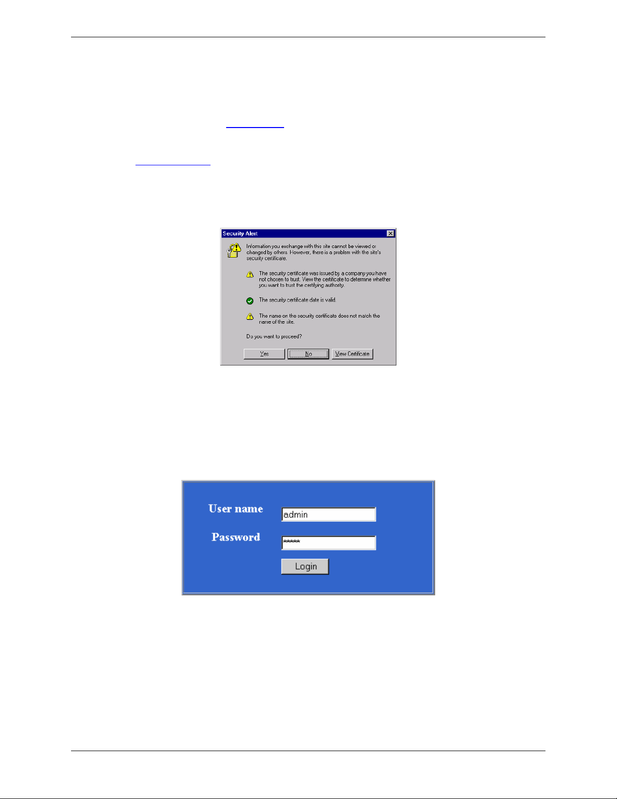
4. Bring up your Web browser on the workstation. At the Web browser’s address line, type the default Gateway
address of https://192.168.2.1 and press the Enter key. In some environments, one or more Security Alert
screen(s) display.
Note: Make sure your PC’s IP address is in the same network as the router’s IP Address. WINIPCFG and
IPCONFIG are tools for finding a computer’s default gateway and MAC address. In Windows 98/ME you can type
WINIPCFG. In Windows 2000/NT, you can type IPCONFIG.
At the initial Security Alert screen, click Yes and follow any additional on-screen prompts. (This step is
eliminated when you have generated a CA certificate at Administration > Site Certificate)
5. The Login screen is displayed. Type the default User name of admin (all lower-case), tab to the Password
entry and type the default Password of admin (all lower-case), and click on Login. The User and Password
entries are case-sensitive (both must be all lower-case). The password can be up to 12 characters. You will want
to change User and Password entries from the default (admin) to something else. (If Windows displays the
AutoComplete screen, for security reasons, you may want to click No to tell the Windows OS to not remember
the Password.)
Multi-Tech Systems, Inc. RF760/660/600VPN Tunnel Examples Reference Guide (S000308D) 6
Page 7

Example 1 – Site A
6. If someone else is already logged in to the RouteFinder, or you were logged in recently, the message below is
displayed.
Click the Yes button. The Login screen displays. Repeat step 5.
7. The Web Management Home screen is displayed.
Multi-Tech Systems, Inc. RF760/660/600VPN Tunnel Examples Reference Guide (S000308D) 7
Page 8

Example 1 – Site A
8. Click on Administration > System Setup to set the correct zone, date and time for your location.
Administration
System Setup
System Time
Multi-Tech Systems, Inc. RF760/660/600VPN Tunnel Examples Reference Guide (S000308D) 8
Page 9

9. Click on Wizard Setup. Enter information for Site A of this example.
Example 1 – Site A
a) Enter the Administrator Email Address (can be anything). (Example: admin@yourdomain.com)
b) Enter the Host name for the RouteFinder (can be anything). (Example: RF660VPN.Site-A.com)
c) LAN IP Address and Subnet Mask are set at the defaults. This should be acceptable for Site A.
d) Enter the WAN IP Address. This is the PUBLIC STATIC IP address. (Example: 204.26.122.103)
e) Change the Gateway IP address; this is the IP address of the router that connects to the Internet. (Example:
204.26.122.1)
f) Place a checkmark in the Packet Filter Rule: LAN-ANY-ANY-ALLOW box. This enables the rule.
g) Specify any changes to the passwords that you feel are necessary.
h) Click Save to save the settings you just entered.
i) The following screen displays prompting you to save your changes. Click OK.
j) The following screen displays. Saving your settings will take several minutes. Since you kept the LAN IP
address the same, it is not necessary to change this system to a new IP address.
Multi-Tech Systems, Inc. RF760/660/600VPN Tunnel Examples Reference Guide (S000308D) 9
Page 10

Example 1 – Site A
10. Click on Networks & Services > Network. The LAN IP network should already be defined. This is the private
LAN on eth0 at Site A (not shown in this example).
a) Define the IP network that is configured on the remote LAN port (the private LAN on eth0 at Site B) by
entering the following information. After this information is entered, it is added to the Network/Host list on
this screen.
For example: Name = RemoteLAN
IP address = 192.168.10.0
Subnet mask = 255.255.255.0
b) Define the IP address that is configured on the remote WAN port (the public WAN on eth1 at Site B) by
entering the following information. After this information is entered, it is added to the Network/Host list on
this screen.
For example: Name = RemoteWAN_IP
IP address = 204.26.122.3
Subnet mask = 255.255.255.255
After this information is entered, it displays at the bottom of the screen.
RemoteLAN 192.168.10.0 255.255.255.0
RemoteWAN_IP 204.26.122.3 255.255.255.255
11. Click on Packet Filters > Packet Filters Rules.
The rule for LAN should already be present. Add the rule RemoteLAN – Any – Any – ACCEPT.
This allows the Remote LAN at Site B to access the RouteFinder and LAN at Site A.
After the rule is entered, it displays under User Defined Packet Filter Rules.
1 RemoteLAN Any Any ACCEPT
Multi-Tech Systems, Inc. RF760/660/600VPN Tunnel Examples Reference Guide (S000308D) 10
Page 11

12. Click on VPN > IPSec.
Example 1 – Site A
a) Enable VPN Status by placing a check mark in the box and clicking on Save.
b) Leave IKE-Debugging disabled by not placing a check mark in the box.
c) Leave IPSec Debugging disabled by not placing a check mark in the box.
d) Click on Add a manual connection to enter a new IPSec connection.
The Add a Manual Connection screen displays.
a) Connection name
Enter a text name that will identify the connection for you.
b) Compression
Check the compression checkbox to enable IPCOMP, the compression algorithm.
Multi-Tech Systems, Inc. RF760/660/600VPN Tunnel Examples Reference Guide (S000308D) 11
Page 12

c) Authentication Method
Set to ESP 3 DES(MD5-96) for this example. This is the encryption and authentication algorithms
to be used for the respective security services.
d) SPI Base
Set to 0x201 for this example.
e) AH Encryption Key
Set so that it matches at the other VPN.
f) Local WAN IP
Set to WAN for this example. This selects the Interface that will initiate the IPSec tunnel.
g) Local LAN
Set to LAN for this example. This is the local security gateway for which the security services are
to be provided.
h) Remote Gateway IP or FQDN
Set to RemoteWAN_IP for this example. This is the interface in which the IPSec tunnel ends.
i) Remote LAN
Set to RemoteLAN for this example. This is the remote security gateway for which the security
services are to be provided.
j) Save
Click to Save the settings.
The new manual configuration displays at the bottom of this screen.
Example 1 – Site A
Manual configuration: ; SiteA_Man WAN lan RemoteWAN_IP RemoteLAN Edit|Delete
This completes the configuration of the RF660VPN at Site A.
Now, go to the RF660VPN at Site B and access the LAN port from a workstation
as done for Site A.
Multi-Tech Systems, Inc. RF760/660/600VPN Tunnel Examples Reference Guide (S000308D) 12
Page 13

Example 1 – Site B
Example 1 Site B Configuration
Site B Configuration
Follow the same basic procedures as used for Site A.
Note that some parameters are different for Site B.
For detail related to each step, see Site A procedures.
Step 1 – Connect a workstation to the RF660VPN’s LAN port via Ethernet for Site B.
Step 2 – Use the same IP Address as used for Site A (Set the workstation IP address to 192.168.10.1 subnet).
Step 3 – Turn on the power.
Step 4 – Bring up your Web browser on the workstation. At the Web browser address line, type the default
Gateway address: https://192.168.10.1
Step 5 – Follow the Site A User Name and Password login instructions.
Step 6 – If someone else is already logged in to the RouteFinder, or if you were logged in recently, a message
will ask you: Do you want to log the user out?
Click the Yes Button.
The Login screen displays. Repeat step 5.
Step 7 – The Web Management Home screen displays.
Step 8 – Click on Administration > System Setup to set the correct zone, date, and time for your location.
Step 9 – Click on Wizard Setup. Enter information for Site B of this example.
a) Enter the Administrator Email Address (can be anything). (Example: admin@yourdomain.com
b) Enter the Host name for the RouteFinder (can be anything). (Example: RF660VPN.Site-B.com)
c) LAN IP Address and Subnet Mask are set at the defaults. This should be acceptable for Site A.
d) Enter the WAN IP Address. This is the PUBLIC STATIC IP address. (Example: 204.26.122.3)
e) Change the Gateway IP address; this is the IP address of the router that connects to the Internet.
(Example: 204.26.122.1)
f) Place a checkmark in the Packet Filter Rule: LAN-ANY-ANY-ALLOW box. This enables the rule.
g) Specify any changes to the passwords that you feel are necessary.
h) Click Save to save the settings you just entered.
i) A screen displays prompting you to save your changes. Click OK.
j) Another screen displays to tell you not to close your browser while the settings are being saved.
Step 10 – Click on Networks & Services > Network.
Define the IP network configured on the remote LAN port (the private LAN on eth0 at Site B) by
entering the following information.
For example
Name = RemoteLAN
IP address = 192.168.2.0
Subnet mask = 255.255.255.0
Define the IP address that is configured on the remote WAN port (the public WAN on eth1 at
Site B) by entering the following information.
For example
Name = RemoteWAN_IP
IP address = 204.26.122.103
Subnet mask = 255.255.255.255
Step 11 – Click on Packet Filters > Packet Filter Rules. The rule for LAN is already defined. Add the rule
RemoteLAN – Any – Any – ACCEPT. This allows the Remote LAN at Site B to access the
RouteFinder and LAN at Site A.
Step 12 – Click on VPN > IPSec.
Use the same settings as used for Site A, and add a manual connection using the same settings
as used for Site A.
This completes the configuration of the RF660VPN at Site B for Example 1.
and press Enter.
)
Multi-Tech Systems, Inc. RF760/660/600VPN Tunnel Examples Reference Guide (S000308D) 13
Page 14

Example 1 – Testing
Testing Your Configuration for Example 1
You can test your connection between the two RouteFinders using the PING command at a DOS prompt.
Testing the Workstation at Site A
At the Site A workstation connected to LAN port of RF660VPN:
a) At the DOS prompt ping a workstation connected to the LAN port of the RF660VPN at Site B.
Example: Ping 192.168.10.100 <return>
You should see four successful packet transmit/receive statements. If you do not, try several more times.
You may see several initial failures while the two RF660VPNs make a secure connection.
b) If this fails, try to ping the WAN port of the RF660VPN at Site B.
Example: Ping 204.26.122.3
You should see four successful packet transmit/receive statements. If you do not, try several more times.
You may see several initial failures while the two RF660VPNs make a secure connection.
c) If this fails, try to ping the WAN port of the RF660VPN at Site A.
Example: Ping 204.26.122.103
Note: If any of these tests fail then verify that the workstation is connected to the LAN port of the RF660VPN.
The LAN port LINK LED should be on and the ACT LED should blink on each time you ping the RF660VPN.
Also verify that the RF660VPN is configured properly.
Multi-Tech Systems, Inc. RF760/660/600VPN Tunnel Examples Reference Guide (S000308D) 14
Page 15

Example 1 – Testing
Testing the Workstation at Site B:
At the Site B workstation connected to LAN port of RF660VPN:
a) At the DOS prompt ping a workstation connected to the LAN port of the RF660VPN at Site A.
Example: Ping 192.168.2.100 <return>
You should see four successful packet transmit/receive statements. If you do not, try several more times.
You may see several initial failures while the two RF660VPNs make a secure connection.
b) If this fails, try to ping the WAN port of the RF660VPN at Site A.
Example: Ping 204.26.122.103
You should see four successful packet transmit/receive statements. If you do not, try several more times.
You may see several initial failures while the two RF660VPNs make a secure connection.
c) If this fails, try to ping the WAN port of the RF660VPN at Site B.
Example: Ping 204.26.122.3
Note: If any of these tests fail then verify that the workstation is connected to the LAN port of the RF660VPN.
The LAN port LINK LED should be on and the ACT LED should blink on each time you ping the RF660VPN.
Also verify that the RF660VPN is configured properly.
Multi-Tech Systems, Inc. RF760/660/600VPN Tunnel Examples Reference Guide (S000308D) 15
Page 16

Example 2 – Overview
Example 2
This example provides a sample RouteFinder configuration and related address scheme for an application employing
LAN-to-LAN IPSec Pass-Through communication in Manual Mode. This example shows how to configure an
RF760VPN, RF660VPN or RF600VPN at Site A and an RF760VPN, RF660VPN or RF600VPN behind a NAT box at
Site B, so that Site A and B can communicate through a secure connection over the Internet using IPSec PassThrough in Manual Mode.
Multi-Tech Systems, Inc. RF760/660/600VPN Tunnel Examples Reference Guide (S000308D) 16
Page 17

Example 2 – Overview
3
4
4
Example 2 – LAN-to-LAN Configuration Chart
For LAN-to-LAN connectivity, the RF760VPN, RF660VPN and RF600VPN RouteFinders utilize the IPSec protocol to
provide up to 100 tunnels (RF760VPN) with strong 168-bit 3DES encryption using IKE and PSK key management. In
addition, the RF760VPN, RF660VPN and RF600VPN provide high performance with up to 50Mbps (RF760VPN) of
3DES encryption throughput.
Site A - Static IP Addresses (Input These Parameters
For the RF660VPN in the Home Office).
1. Domain name = site-A.com
2. Public Class C = 204.26.122.x
. Networks & Services > Networks
LAN: 192.168.2.0 – 255.255.255.0
RemoteLAN: 192.168.10.0 – 255.255.255.0
RemoteWAN_IP: 204.26.122.3 – 255.255.255.255
. Network Setup > Interface
Default gateway = 204.26.122.1
Host name = RF660VPN.site-A.com
Eth0 = LAN, 192,168.2.1, 255.255.255.0
Eth1 = WAN, 204.26.122.103, 255.255.255.0
Eth2 = DMZ (don’t care)
5. Packet Filters > Packet Filter Rules
LAN – Any – Any – Accept
RemoteLAN – Any – Any – Accept
6. VPN > IPSec
Check and Save VPN Status
Add a Manual connection:
Connection name = SiteA
Authentication Method = ESP3-DES(MD5-96)
SPI Base = 0x201
ESP Encryption Key (must be the same at both sites)
Authentication Key (must be the same at both sites)
Local WAN IP = WAN
Local LAN = LAN
Remote Gateway IP = RemoteWAN_IP
Remote LAN = RemoteLAN
Site B - Static IP Addresses (Input These Parameters
For the RF660VPN in the Branch Office
1. Domain name = site-B.com
2. Public Class C = 204.26.122.x
3. Networks & Services > Networks
LAN: 192.168.10.0 – 255.255.255.0
RemoteLAN: 192.168.2.0 – 255.255.255.0
RemoteWAN_IP: 204.26.122.103 –255.255.255.255
. Network Setup > Interface
Default gateway = 192.168.0.1
Host name = RF660VPN.site-B.com
Eth0 = LAN, 192.168.10.1, 255.255.255.0
Eth1 = WAN, 192.168.0.2, 255.255.255.0
Eth2 = DMZ (don’t care)
5. Packet Filters > Packet Filter Rules
LAN – Any – Any – Accept
RemoteLAN – Any – Any – Accept
6. VPN > IPSec
Check and Save VPN Status
Add a Manual connection:
Connection name = SiteB
Authentication Method = ESP3-DES(MD5-96)
SPI Base = 0x201
ESP Encryption Key (must be the same at both sites)
Authentication Key (must be the same at both sites)
Local WAN IP = WAN
Local LAN = LAN
Remote Gateway IP = RemoteWAN_IP
Remote LAN = RemoteLAN
Multi-Tech Systems, Inc. RF760/660/600VPN Tunnel Examples Reference Guide (S000308D) 17
Page 18

Example 2 – Site A and Site B
Site A Configuration To configure the RF760VPN/RF660VPN/RF600VPN at Site A,
follow the same procedure as in Example 1 – Site A.
Site B Configuration
Configure the RF760VPN/RF660VPN/RF600VPN at Site B following the procedure in Example 1– Site B, but
use the Wizard Setup to change the WAN IP Address to 192.168.0.2 and the Gateway to 192.168.0.1.
Configure the NAT box for an IPSec Pass-Through by specifying the IP address and subnet mask assigned by
the ISP for Site B (Ex: 204.26.122.3). Then specify the ISP Gateway Address (Ex: 204.26.122.103).
NAT Box Configuration at Site B.
Multi-Tech Systems, Inc. RF760/660/600VPN Tunnel Examples Reference Guide (S000308D) 18
 Loading...