

Page 1
Product Update
BIOS Upgrade for MT586SBC and RAS96
2/19/99
PN 82097650
The procedures that follow detail the process of replacing the BIOS chip currently residing on your
MT586SBC or RAS96 board with the new BIOS chip included in this upgrade kit. Please read all
instructions carefully before beginning the upgrade, to insure that system settings are not lost.
MT586SBC BIOS Replacement Procedure
Step Procedure
1 Prior to upgrading, reboot the segment to be upgraded and press the DELETE key to run the
BIOS setup utility. Record the basic system settings, including hard drive configuration, and keep
the setting notes as a reference for configuration of the new BIOS, later in this procedure.
2 Remove power from the segment to be upgraded, detach all internal and external cable
connections and remove the MT586SBC from it’s chassis.
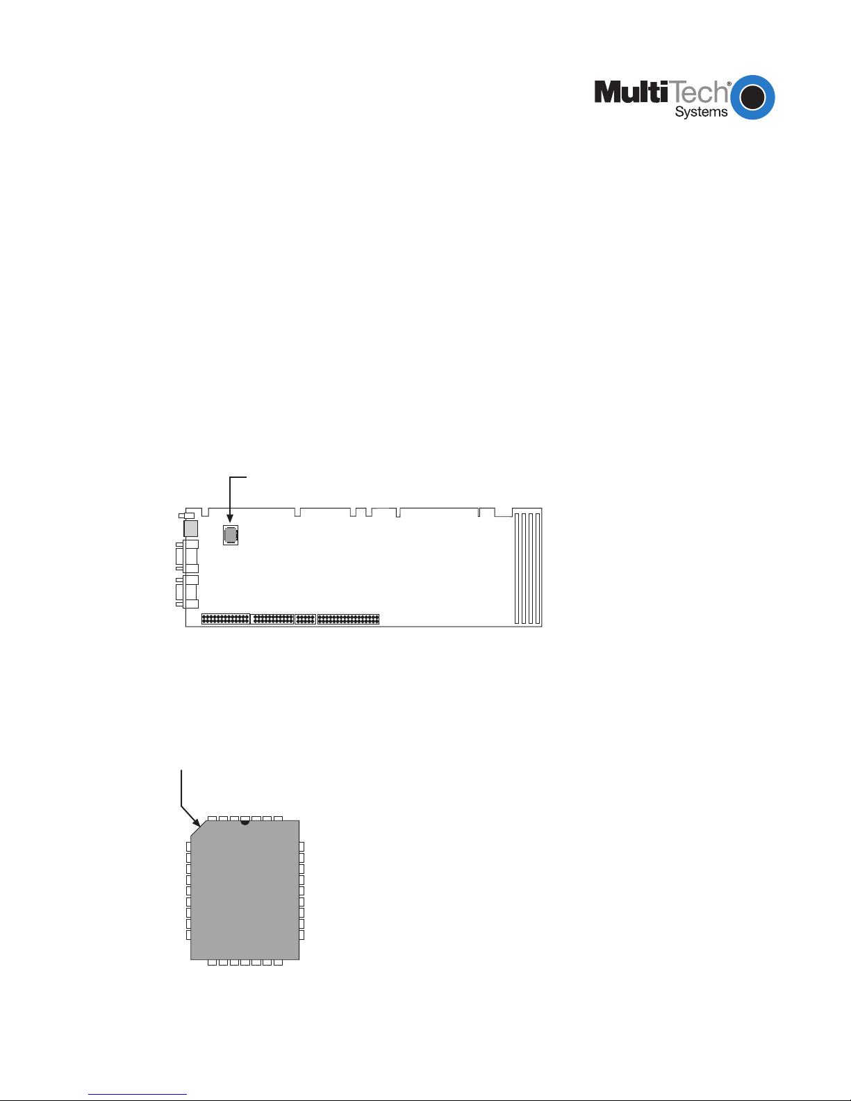
3 Lay the MT586SBC board on a flat, stable, anti-static surface and locate the 32-pin PLCC socket
and BIOS chip on the board (see Figure 1).
BIOS Chip
Figure 1. BIOS Chip/Socket Location
4 Note the orientation of the chip inside the socket using the orientation notch on the chip (see
Figure 2). Later in this procedure you will be placing the new chip in the socket using the same
orientation.
Orientation
Notch
Figure 2. BIOS Chip Orientation
1 of 4
Page 2

5 Use the extractor tool provided with your upgrade kit to remove the 32-pin, PLCC BIOS chip from
it’s socket by gently prying one corner of the chip part-way out of the socket and then prying the
opposite corner of the chip until the chip pops out of the socket.
Note: Do not attempt to pry the chip completely out of the socket using only one corner. Doing so
could result in damage to the chip socket.
6 Orientate the new BIOS chip on top of the chip socket so that the orientation notch is in the
correct location (see Figure 2).
7 Gently press the chip into the socket until it snaps into place.
8 Install the MT586SBC into it’s chassis, being sure to re-connect all internal and external cables.
9 Apply power to the segment, and as the segment boots, press the DELETE key to run the BIOS
setup utility.
10 From the BIOS setup menu, select “LOAD BIOS DEFAULTS” and verify that settings match the
original BIOS (using your configuration notes from Step 1), making any necessary modifications.
Note: It is recommended that you
disable
the Daylight Savings Time feature in BIOS Setup. It
has been observed that Windows NT will experience certain anomalies if the Daylight Savings
Time feature is enabled.
11 Select “IDE HDD AUTO DETECTION” and choose the hard drive configuration that matches the
settings you noted in Step 1.
12 Select “SAVE & EXIT SETUP” to save all changes and reboot the system.
Note: If you have problems booting to the Hard Drive or see corrupt files that were fine before the
BIOS upgrade, DO NOT try to correct these problems using CHKDSK or SCANDISK. Reboot and go
into SETUP and verify the hard drive settings match those used before the upgrade. If problems
continue, reinstall the original BIOS and use original hard drive settings, then reboot.
2 of 4
Page 3

RAS96 BIOS Replacement Procedure
Step Procedure
1 Prior to upgrading, reboot the segment to be upgraded and press the DELETE key to run the
BIOS setup utility. Record the basic system settings, including hard drive configuration, and keep
the setting notes as a reference for configuration of the new BIOS, later in this procedure.
2 Remove power from segment, detach external cables from the RAS96 card, remove it from the
CommPlete chassis.
3 Lay the RAS96 board on a flat, stable, anti-static surface. To gain access to the 32-pin PLCC
socket and BIOS chip on the board, you must first remove the hard drive (see Figure 1).
44-pin Connector
Hard Disk
T1 Card 1 (T1
and Dual T1
Models Only)
T1 Card 2
(Dual T1
Models Only)
Figure 1. Hard Drive Removal
4 Turn the RAS96 board upside down, locate the four drive mounting screws that secure the hard
drive to the RAS96 board, and remove all four screws. Retain the screws for re-installation.
5 Being sure to support the drive (now unsecured), turn the board right-side up and disconnect the
44-pin ribbon cable from the connector on the board (see Figure 1), noting the Pin 1 (red)
orientation, and set the drive aside.
6 Locate the 32-pin PLCC socket and BIOS chip on the board (see Figure 2).
BIOS Chip
CPU
Figure 2. BIOS Chip/Socket Location
3 of 4
Page 4

7 Note the orientation of the chip inside the socket using the orientation notch on the chip (see
Figure 3). Later in this procedure you will be placing the new chip in the socket using the same
orientation.
Orientation
Notch
Figure 3. BIOS Chip Orientation
8 Use the extractor tool provided with your upgrade kit to remove the 32-pin, PLCC BIOS chip from
it’s socket by gently prying one corner of the chip part-way out of the socket and then prying the
opposite corner of the chip until the chip pops out of the socket.
Note: Do not attempt to pry the chip completely out of the socket using only one corner. Doing so
could result in damage to the chip socket.
9 Orientate the new BIOS chip on top of the chip socket so that the orientation notch is in the
correct location (i.e., pin 1 of the BIOS chip mates with pin 1 of the chip socket).
10 Gently press the chip into the socket until it snaps into place.
11 Re-attach the hard drive ribbon cable to the RAS96 board, being sure to match Pin 1 on the
cable to Pin one of the connector.
12 Secure the drive to the board using the drive mounting screws removed in Step 4.
13 Install the RAS96 into the chassis and connect all external cables.
14 Apply power to the segment, and as the segment boots, press the DELETE key to run the BIOS
setup utility.
15 From the BIOS setup menu, select “LOAD BIOS DEFAULTS” and verify that settings match the
original BIOS (using your configuration notes from Step 1), making any necessary modifications.
Note: It is recommended that you
disable
the Daylight Savings Time feature in BIOS Setup. It
has been observed that Windows NT will experience certain anomalies if the Daylight Savings
Time feature is enabled.
16 Select “IDE HDD AUTO DETECTION” and choose the hard drive configuration that matches the
settings you noted in Step 1.
17 Select “SAVE & EXIT SETUP” to save all changes and reboot the system.
Note: If you have problems booting to the Hard Drive or see corrupt files that were fine before the
BIOS upgrade, DO NOT try to correct these problems using CHKDSK or SCANDISK. Reboot and go
into SETUP and verify the hard drive settings match those used before the upgrade. If problems
continue, reinstall the original BIOS and use original hard drive settings, then reboot.
4 of 4
 Loading...