

Page 1
ISDN ProxyServer
Model MTPSR1-202ST
User Guide
Page 2

User Guide
S0000005 Revision A
ProxyServer 200-Series (Model MTPSR1-202ST)
This publication may not be reproduced, in whole or in part, without prior expressed written permission from
Multi-Tech Systems, Inc. All rights reserved.
Copyright © 1999, by Multi-Tech Systems, Inc.
Multi-Tech Systems, Inc. makes no representations or warranties with respect to the contents hereof and
specifically disclaims any implied warranties of merchantability or fitness for any particular purpose.
Furthermore, Multi-Tech Systems, Inc. reserves the right to revise this publication and to make changes from
time to time in the content hereof without obligation of Multi-Tech Systems, Inc. to notify any person or
organization of such revisions or changes.
Record of Revisions
Revision Description
A Manual released. All pages at revision A.
(10/22/99)
Patents
This Product is covered by one or more of the following U.S. Patent Numbers: 5.301.274; 5.309.562;
5.355.365; 5.355.653; 5.452.289; 5.453.986. Other Patents Pending.
TRADEMARK
The Multi-Tech logo and ProxyServer are registered trademarks or trademarks of Multi-Tech Systems, Inc.
Adobe and Acrobat are trademarks of Adobe Systems Incorporated.
Microsoft, Windows, and Windows NT are registered trademarks or trademarks of Microsoft Corporation in
the United States and/or other countries.
Multi-Tech Systems, Inc.
2205 Woodale Drive
Mounds View , Minnesota 55112
(612) 785-3500 or (800) 328-9717
Fax 612-785-9874
Tech Support (800) 972-2439
BBS (612) 785-3702 or (800) 392-2432
Internet Address: http://www.multitech.com
Page 3

Contents
Chapter 1 - Introduction and Description
Introduction ................................................................................................................................................ 6
Preview of this Guide ................................................................................................................................. 6
Front Panel................................................................................................................................................. 8
Back Panel ................................................................................................................................................. 9
ISDN Connector................................................................................................................................... 9
Phone Connector................................................................................................................................. 9
Ethernet 10Base-T Connector ............................................................................................................. 9
Command Port Connector ................................................................................................................... 9
Power Connector ................................................................................................................................. 9
On/Off Switch....................................................................................................................................... 9
Specifications ........................................................................................................................................... 10
Ethernet Port...................................................................................................................................... 10
Command Port................................................................................................................................... 10
ISDN Port........................................................................................................................................... 10
Phone Port......................................................................................................................................... 10
Electrical/Physical.............................................................................................................................. 10
Requirement ...................................................................................................................................... 10
Chapter 2 - Installation
Introduction .............................................................................................................................................. 12
Unpacking ................................................................................................................................................ 12
Cabling ..................................................................................................................................................... 13
Adding RAM ............................................................................................................................................. 14
Chapter 3 - Software Loading and Configuration
Introduction .............................................................................................................................................. 16
Before You Start Loading your Software .................................................................................................. 16
Network Configuration ....................................................................................................................... 16
Call Control Parameters .................................................................................................................... 17
Data Control....................................................................................................................................... 17
Loading your Software ............................................................................................................................. 18
IP Wizard Setup................................................................................................................................. 21
Setting Up Your Remote User Database.................................................................................................. 24
Chapter 4 - ProxyServer Software
Introduction .............................................................................................................................................. 28
Before Y ou Begin ..................................................................................................................................... 28
Proxy Setup.............................................................................................................................................. 29
Changing IP Parameters .......................................................................................................................... 30
Changing WAN Port Parameters ............................................................................................................. 33
Internet Setup........................................................................................................................................... 37
Enabling the DHCP Server....................................................................................................................... 39
Adding ProxyServer Applications............................................................................................................. 40
Enabling the Virtual Server....................................................................................................................... 42
Enabling Remote Servers ........................................................................................................................ 45
Telnet/TFTP ....................................................................................................................................... 45
WEB Server....................................................................................................................................... 45
Statistics................................................................................................................................................... 47
Running Diagnostics ................................................................................................................................ 48
WAN Device Configuration....................................................................................................................... 48
iii
Page 4

Chapter 5 - Client Setup
Introduction .............................................................................................................................................. 50
Before you Begin...................................................................................................................................... 50
Configuring in Windows 98/95.................................................................................................................. 51
Installing TCP/IP (Win98/95) ................................................................................................................... 58
Configuring in Windows NT...................................................................................................................... 59
Installing TCP/IP (WinNT) ....................................................................................................................... 65
Chapter 6 - RAS Dial-Out Redirector
Introduction .............................................................................................................................................. 68
Installing and Configuring the WINMCSI Modem-Sharing Software ........................................................ 68
Running the WINMCSI Workstation Software.......................................................................................... 74
Chapter 7 - Remote Configuration
Introduction .............................................................................................................................................. 78
Remote Configuration .............................................................................................................................. 78
Chapter 8 - ProxyServer Management
Telnet ProxyServer Configuration ............................................................................................................ 82
WEB Management ................................................................................................................................... 85
Chapter 9 - Service, Warranty and Tech Support
Introduction .............................................................................................................................................. 88
Limited Warranty ...................................................................................................................................... 88
On-line Warranty Registration............................................................................................................ 88
Tech Support ............................................................................................................................................ 89
Recording ProxyServer Information................................................................................................... 89
Service ..................................................................................................................................................... 90
About the Multi-Tech BBS ........................................................................................................................ 91
Logging on to the Multi-Tech BBS...................................................................................................... 91
Downloading a File ............................................................................................................................ 91
Reading a Message ........................................................................................................................... 92
Leaving a Message............................................................................................................................ 92
Bulletins ............................................................................................................................................. 92
About the Internet..................................................................................................................................... 92
Ordering Accessories ............................................................................................................................... 93
Appendixes
Appendix A - Cabling Diagrams................................................................................................................ 96
Appendix B - Script Commands ............................................................................................................... 97
Appendix C - Regulatory Compliance Information ................................................................................... 99
Appendix D - AT Commands .................................................................................................................. 102
Appendix E - TCP/IP .............................................................................................................................. 122
Glossary of Terms
Index
iv
Page 5

Chapter 1 - Introduction and Description
Page 6
ProxyServer User Guide
Introduction
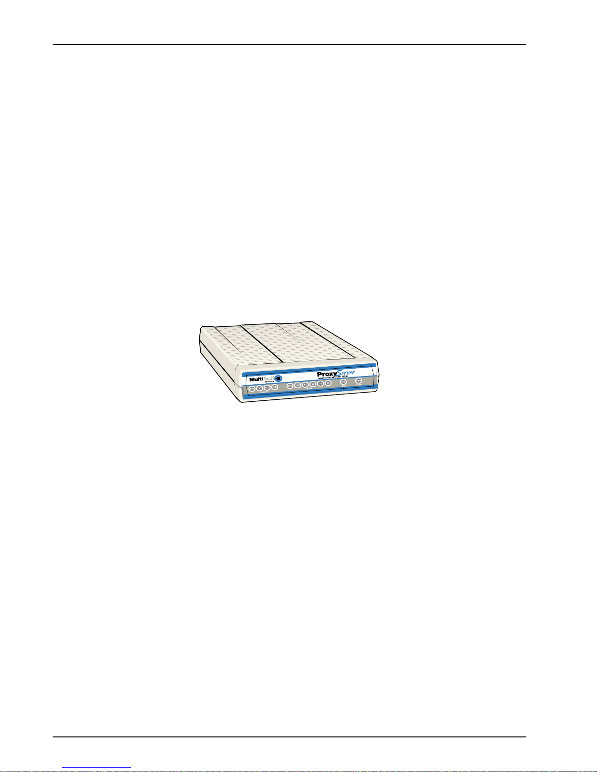
Welcome to Multi-Tech’s new ProxyServer 200-Series, model MTPSR1-202ST, a single, secure
gateway that provides multiple LAN users with high performance Internet access. The ProxyServer
functions as a TCP/IP proxy server that resides on the outer edge of your firewall and provides Basic
Rate ISDN Service using its internal 2B+D terminal adapter. The MTPSR1-202ST supports dial in
Remote Access Server (RAS), RAS Dial-Out Redirector, and can act as an asynchronous Gateway .
The MTPSR1-202ST ProxyServer features a 10Base-T port for local LAN connection, Command
Port for configuration, and an internal 2B+D ISDN terminal adapter for 64 Kbps per channel or 128
Kbps effective bandwidth when software BONDing (Bandwidth ON Demand) using ML-PPP is
employed. BONDing starts with 64K and when a certain threshold is reached, the second 64K
channel is brought up and bonded.
The MTPSR1-202ST supports client and site filtering, dial-in remote access from a PPP client,
includes Network Address translation (NAT) allowing corporate web, FTP, and mail servers access
from the Internet, dials on-demand for link establishment as Internet services are requested, and
handles HTTP, FTP, POP3, DNS, NNTP, TFTP, IRC, SMTP, Gopher, Finger , rlogin, and Citrix
requests.
System management is provided through the command port using bundled Windows
provides easy-to-use configuration menus.
®
software which
Figure 1. ISDN ProxyServer
Preview of this Guide
This guide describes the ISDN ProxyServer and tells you how to install and configure the unit. The
information contained in each chapter is as follows:
Chapter 1 - Introduction and Description
This chapter describes the ISDN ProxyServer and provides descriptions of the front panel indicators
and back panel connectors and switch. A list of relevant specifications is provided at the end of the
chapter.
Chapter 2 - Installation
This chapter provides information on unpacking and cabling your ISDN ProxyServer. The installation
procedure describes each cable connection starting with connecting the power cord, Command port,
LAN and finally the WAN.
Chapter 3 - Software Loading and Configuration
This chapter details the software loading which configures the IP port and WAN link. The
ProxyServer software is Windows-based. Each field within a dialog box that is alterable is described.
6
MTPSR1-202ST
Page 7

Chapter 4 - Software
This chapter describes the ProxyServer 200-Series software package designed for the Windows
environment. The ProxyServer Program Group has five icons that allow for ProxyServer
configuration, Download Default Setup, Download Firmware Update, Configuration Port Setup, and
WAN device configuration from the program manager . Each field within a dialog box is explained in
detail and when fields relate to each other, that relationship is explained.
Chapter 5 - Client Setup
This chapter provides information for enabling and configuring multiple Windows 98/95 or NT® PC
users for Internet access via the ProxyServer.
Chapter 6 - RAS Dial-Out Redirector
This chapter describes how Multi-Tech’s Remote Access Server for Microsoft network users enables
users to dial out and fax out through the MTPSR1-202ST. It provides information on installing and
configuring the WINMCSI modem-sharing software.
Chapter 7 - Remote Configuration
This chapter provides procedures for changing the configuration of a remote ProxyServer. Remote
configuration allows you to change the configuration of a unit by simply connecting two modems
between the two ProxyServers and remotely controlling the unit.
Chapter 1 - Introduction and Description
Chapter 8 - ProxyServer Management
This chapter describes a typical Telnet Client application and discusses web browser management.
Chapter 9 - Service, Warranty and Tech Support
This chapter provides instructions on getting service for your ProxyServer at the factory , a statement
of the limited warranty, information about our Internet web site, and space for recording information
about your ProxyServer prior to calling Multi-Tech’s Technical Support.
MTPSR1-202ST
7
Page 8
ProxyServer User Guide
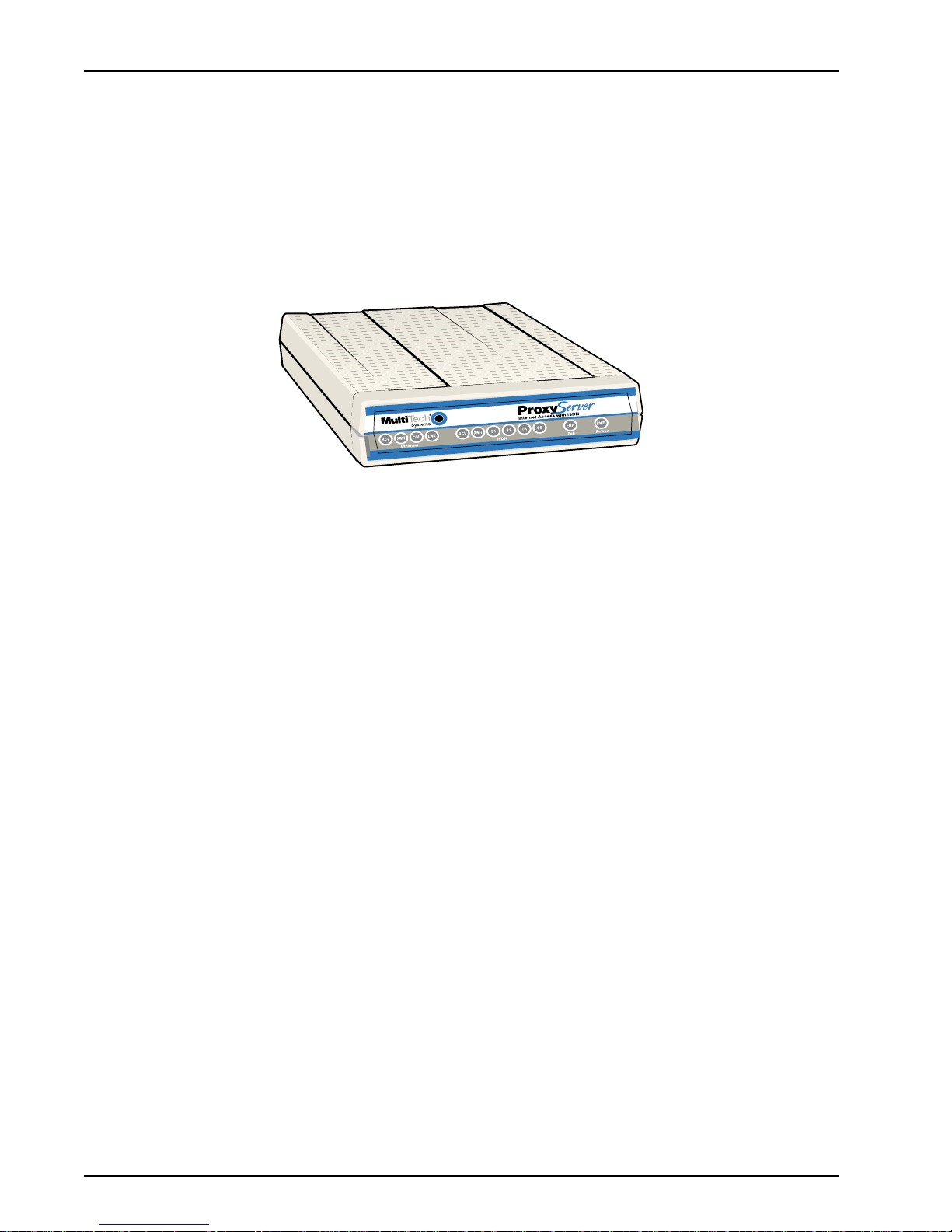
Front Panel
The front panel of the ISDN ProxyServer contains three groups of LEDs that provide the status of the
Ethernet LAN connection, the ISDN WAN connection, and the general status of the ProxyServer (Fail
and Power).
The Ethernet LAN LEDs display the activity of the LAN if the ProxyServer is connected to the LAN,
transmitting or receiving packets, and if a collision is occurring. The ISDN LEDs, or WAN port LEDs,
display the status of the port and show if the link is ready to transmit or receive serial data, and if one
or both Bearer Channels are active. The general group of LEDs indicates whether the self test
passed or failed and if the power On/Off switch on the back of the ProxyServer is set to On.
Figure 1-2. Front Panel
Ethernet
RD Receive Data indicator blinks when packets are being received from the local area network.
TD Transmit Data indicator blinks when packets are being transmitted to the local area network.
CL Collision indicator lights when a collision is in progress; that is, when two nodes are
transmitting packets at the same time.
LK Link indicator lights indicating that the ProxyServer is connected to the local area network.
ISDN
RCV Receive indicator blinks when the ISDN line is receiving data.
XMT Transmit indicator blinks when the ISDN line is transmitting data.
B1 Bearer Channel 1 indicator is ON steady when an active data connection is present. Slowly
blinks when an active analog connection is present. Blinks fast when ringing.
B2 Bearer Channel 2 indicator is ON steady when an active data connection is present. Slowly
blinks when an active analog connection is present. Blinks fast when ringing.
TR Terminal Ready (TR) indicator lights when the ProxyServer is dialing and remains ON as
long as a link connection is available.
CS The Clear to Send (CS) indicator lights during any communication with the Central Office
over the ISDN Line.
General
Fail Fail indicator lights when a self test fails to complete as expected and during boot-up.
Power The power indicator lights when the ON/OFF Switch is in the ON position.
8
MTPSR1-202ST
Page 9
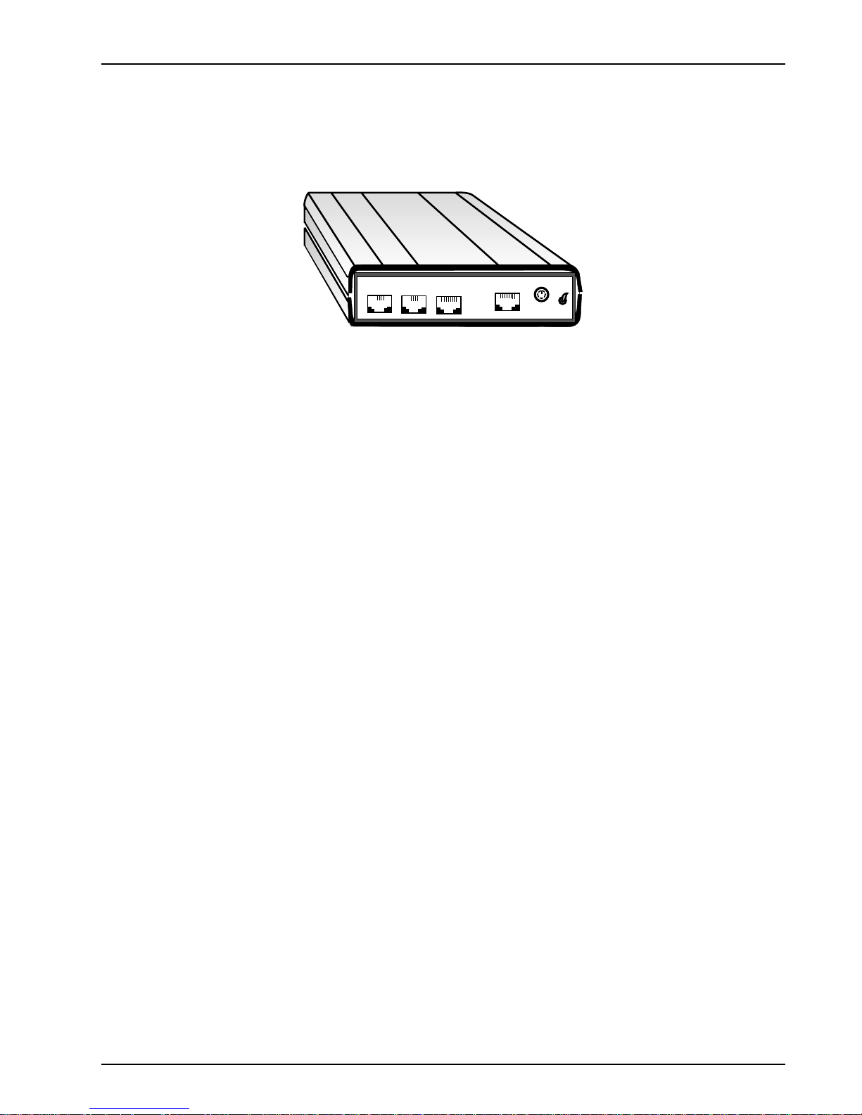
Back Panel
The cable connections for the ProxyServer are made at the back panel. Three groups of cables are
used on the ProxyServer -- the Command Port, ISDN, and Ethernet. The cable jacks are shown in
Figure 1-3 and defined in the following groups.
Chapter 1 - Introduction and Description
ISDN Connector
The ISDN connector (an RJ-45 jack) is used to connect the ProxyServer to the WAN.
Phone Connector
The PHONE connector (an RJ-1 1 jack) can be used to connect an analog telephone, fax machine, or
modem to your ProxyServer.
Ethernet 10Base-T Connector
The Ethernet 10Base-T connector (an RJ-45 jack) is used to connect the ProxyServer to a 10 MB
LAN using unshielded twisted cable.
Command Port Connector
The Command connector (CMD) is used to configure the ProxyServer using a PC with a serial port
and running Windows software. The Command connector is an RJ-45 jack and is used with the RJ45 to DB-9 command port cable provided with your ProxyServer. The command port is only used to
connect the ProxyServer directly to the PC for local configuration and management.
ISDN
PHONE
10BASE T
COMMAND PORT
Figure 1-3. Back Panel
POWER
ON
OFF
Note: If your PC has a DB-25 (25-pin) serial port connector, you will need to obtain a DB-9 (9-pin,
male) to DB-25 adapter. Connect the DB-25 end of this adapter to the serial port on your PC, and
then connect the DB-9 (9-pin, female) end of the Command Port cable to the adapter.
Power Connector
The POWER connector (a 6-pin circular DIN connector) is used to connect the external power supply
to the ProxyServer. A separate power cord is used to connect the power supply to a live AC
grounded outlet.
On/Off Switch
The power switch applies DC power to the ProxyServer.
MTPSR1-202ST
9
Page 10

ProxyServer User Guide
Specifications
• Two-wire Basic Rate (2B+D) ISDN S/T interface
• EuroISDN (NET3), VN4, 1TR6, INS64, NI-1, AT&T 5ESS, DMS-100 switch capability
• SoftBond B-Channel Protocols
• ISDN interface with 64 Kbps per channel or 128 Kbps effective bandwidth when software
BONDing is employed
• Ethernet LAN Interface - 10Base-T (twisted pair) connector
• ISDN Interface - RJ-45 jack
• PHONE interface - RJ-11 jack
• Command Port - 19.2 Kbps, Asynchronous
• One 1 Mb by 32 bytes at 70 nanoseconds SIMM is 4 Mb DRAM
Caution: SIMM speed and size cannot be mixed
• 1 Mb of Flash memory (on two PROMs)
Ethernet Port
• One Ethernet Interface - 10Base-T (twisted pair) RJ-45 jack
Command Port
• Single 19.2 Kbps asynchronous Command Port using a short RJ-45-to-DB9 cable to connect
dircetly to PC
ISDN Port
• Two-wire ISDN Basic Rate 2B+D S/T interface at 128 Kbps
Phone Port
• Single analog interface
Electrical/Physical
• Voltage - 115 VAC (Standard), 240 Volts AC (Optional)
• Frequency - 47 to 63 Hz
• Power Consumption - 10 Watts
• Dimensions - 1.625" high x 6" wide x 9" deep
5.63 cm high x 22.34 cm wide x 33.51 cm deep
• Weight - 2 pounds (.92 kg)
Requirement
• PC with Windows 3.1x or Windows 98/95 and Windows NT, and one serial COM port to
connect to the Command Port of the ProxyServer
10
MTPSR1-202ST
Page 11

Chapter 2 - Installation
Page 12
ProxyServer User Guide
Introduction
This chapter describes how to unpack and cable your ProxyServer. The unpacking section describes
the contents of the shipping box and shows how the ProxyServer is packaged. The installation
procedure describes each cable connection and shows where that cable is connected to the
ProxyServer.
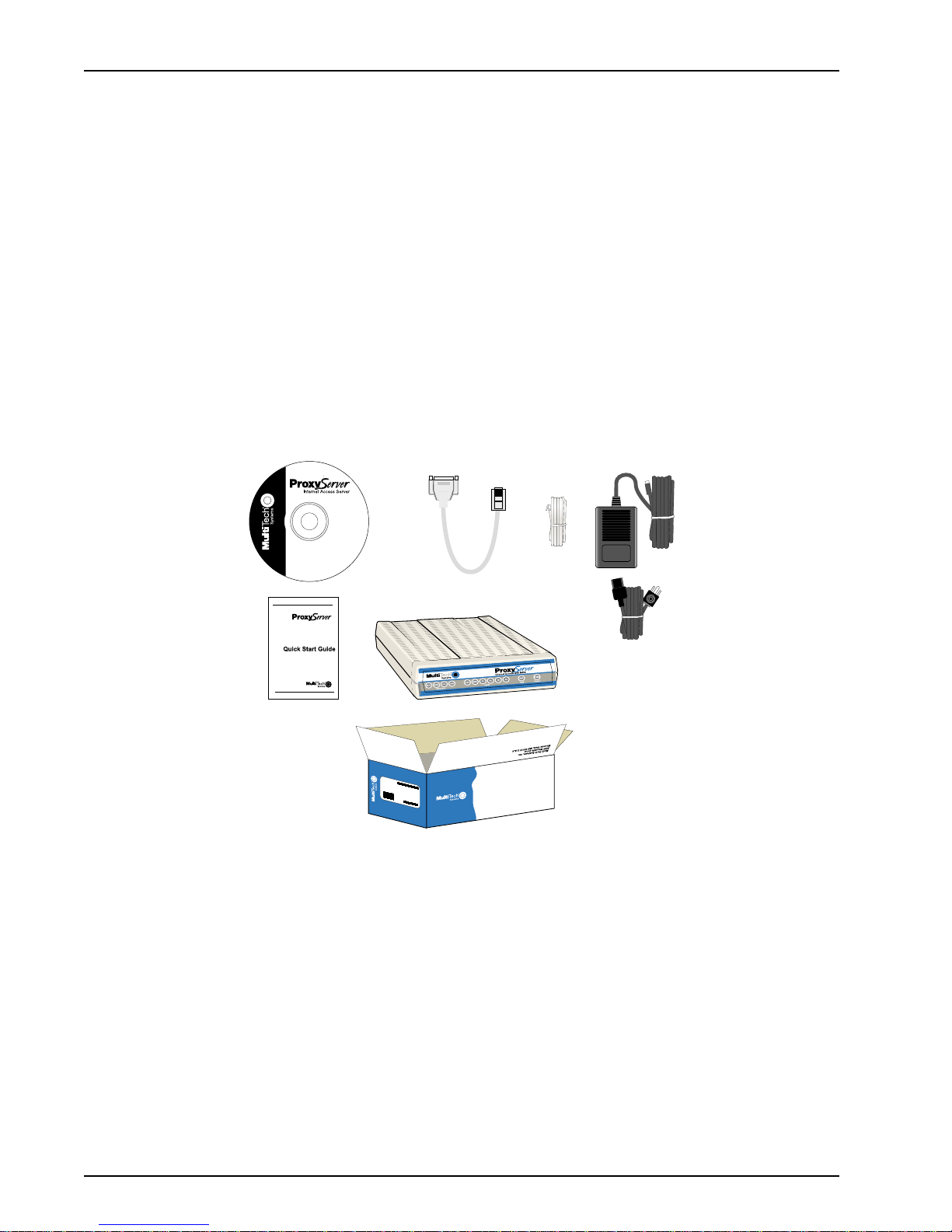
Unpacking
The shipping box contains the ProxyServer, external power supply, an RJ-45 to phone jack cable, an
RJ-45 to DB-9 Command port cable, your Quick Start Guide, and the ProxyServer CD with the
ProxyServer Software and ProxyServer User Guide (in Adobe AcrobatTM format). Inspect the
contents for signs of any shipping damage. If damage is observed, do not power up the unit, contact
Multi-Tech’s Technical Support for advice (refer to Chapter 9). If no damage is observed, place the
ProxyServer in its final location and perform the cabling procedure.
Save the shipping box in case reshipment is necessary .
www.multitech.com
MADE IN U.S.A
MADE IN U.S.A
Figure 2-1. Unpacking
12
MTPSR1-202ST
Page 13
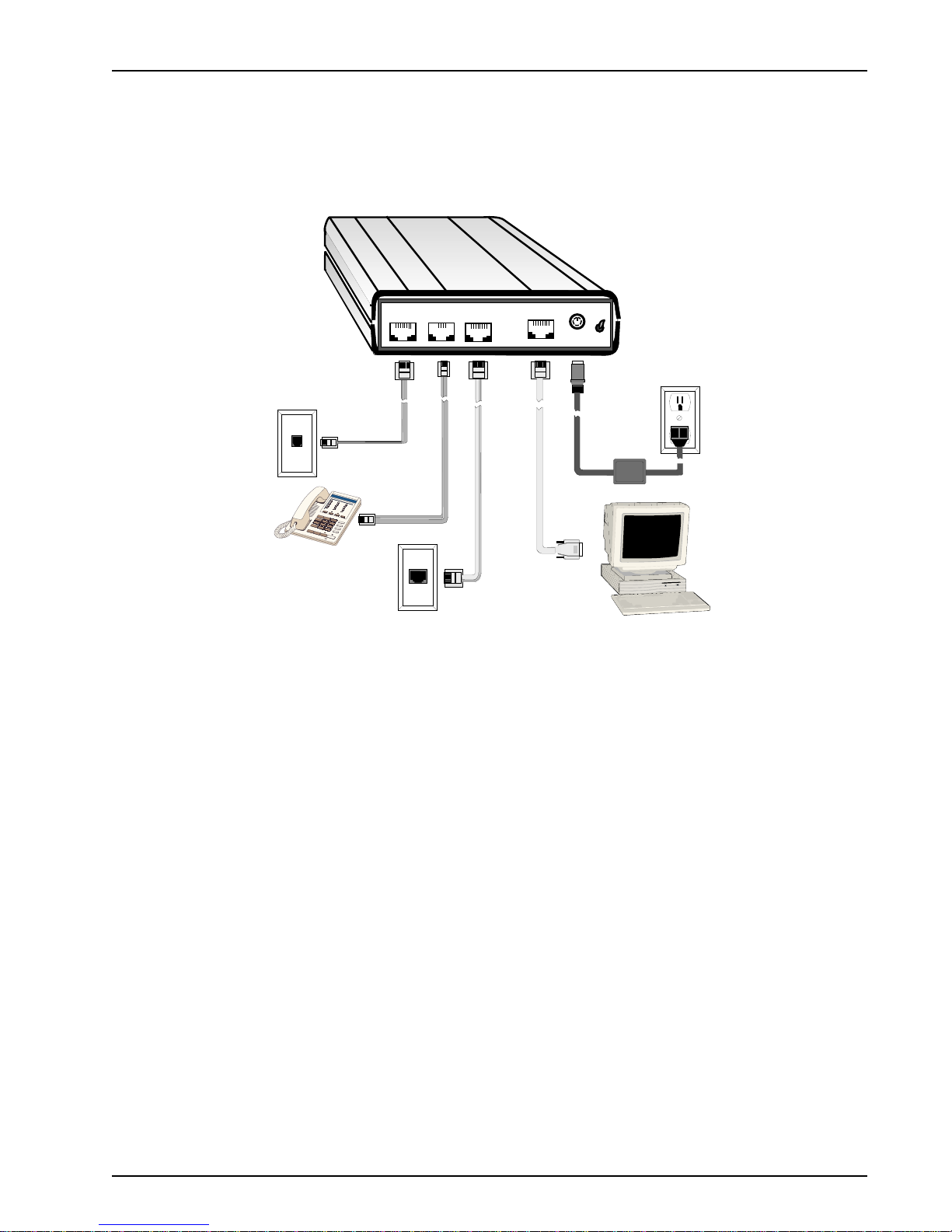
Cabling
elco
Connection
Ethernet
PC
Connection
Power
Connection
Optional
The cable connections include the connection for your Ethernet, a short adapter cable to connect to
your PC for software loading, and finally your power connection. If additional RAM needs to be
added, refer to the “Adding RAM” section in this chapter. Figure 2-2 shows the ProxyServer’s
external connections.
Chapter 2 - Installation
TTelco
Connection
Optional
PHONE
ISDN
Ethernet
Connection
10BASE T
COMMAND PORT
Connection
PC
POWER
ON
OFF
Power
Connection
Figure 2-2. Back Panel Connections
1. Connect the external power supply (included with your ProxyServer) to a live AC outlet. Then
connect the other end to the 6-pin circular DIN POWER connector on the back panel of the
ProxyServer as shown in Figure 2-2.
2. Connect the ProxyServer to a PC using the short RJ-45 to DB-9 cable provided with your unit.
Connect the RJ-45 plug to the COMMAND PORT on the ProxyServer and the other end to a
serial port (COM1 to COM4) on your PC.
3. To make the network connection, connect one end of an RJ-45 (UTP) cable to the 10BASE-T
connector on the back of the ProxyServer. Connect the other end of the cable to your LAN.
4. Connect one end of an RJ-45 cable to the ISDN port on the back of the unit and connect the
other end to the ISDN Telephone Network (Telco wall jack).
5. Turn on power to the ProxyServer by setting the ON/OFF switch on the back panel to the ON
position. Wait for the Fail LED on the ProxyServer to go OFF before proceeding. This may take
up to two minutes.
MTPSR1-202ST
At this time the ProxyServer is completely cabled. Proceed to Chapter 3 to load your software.
13
Page 14
ProxyServer User Guide
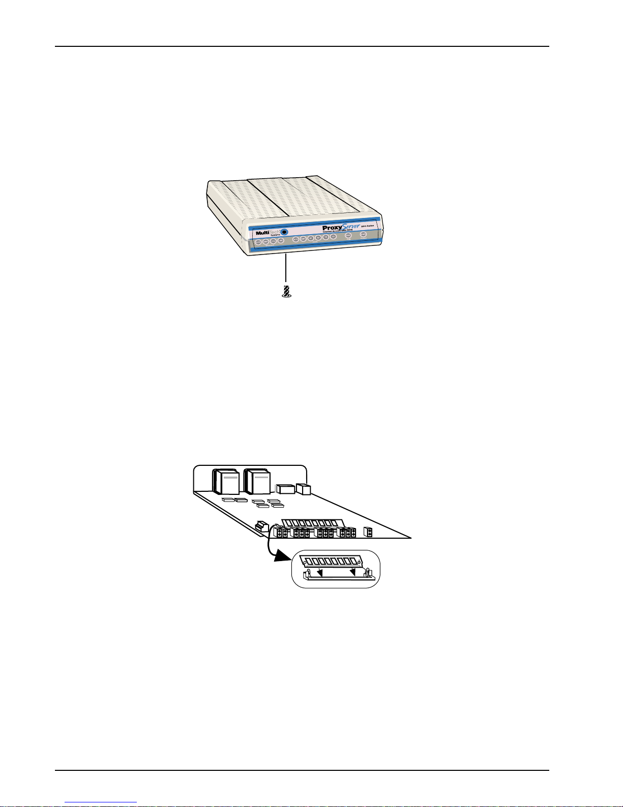
Adding RAM
A second SIMM connector is provided for adding RAM to the ProxyServer. Do the following.
Note: Memory should only be added when required by Multi-Tech Systems.
1. Ensure that the external power supply is disconnected from the ProxyServer.
2. Turn the ProxyServer upside down and remove the cabinet mounting screw located at the center
back of the cabinet (Refer to Figure 2-3).
Cabinet Mounting Screw
(center, back)
Figure 2-3. Cabinet Mounting Screws
3. Turn the ProxyServer right side up, then slide the base out the rear of the cabinet.
4. Position the base so the front panel LEDs are facing toward you (Refer to Figure 2-4).
5. Slant the new SIMM at a 45 0 angle to the back of the base and align the centering notch of the
SIMM with the center tab on the SIMM connector.
6. Gently press down on the ends of the SIMM until the two short vertical white pins enter the holes
at the ends of the SIMM and the two metal side clips snap in place over the SIMM, locking it
down (Refer to Figure 2-4).
Figure 2-4. Installing a SIMM
7. Align the base with the mating guides on the inside of the cabinet, then slide the base all the way
into the cabinet until it stops.
8. Turn the ProxyServer upside down and replace the cabinet mounting screw that was removed in
step 2.
9. Turn the ProxyServer right side up and connect the cables.
14
MTPSR1-202ST
Page 15
Chapter 3 - Software Loading
and Configuration
Page 16

ProxyServer User Guide
Introduction
This chapter covers procedures for loading the ProxyServer software from a Windows PC (Win98/95
or WinNT) and configuring your ProxyServer. Configuration includes setting up the LAN and WAN
port IP addresses, setting up the ISDN configuration default parameters, then downloading the
default setup to the target ISDN ProxyServer.
Before You Start Loading your Software
Consider the following choices before you configure your ProxyServer and record your selections on
the following pages; then refer to them while loading your software.
Network Configuration
ü Network Switch Type_________________________________________
Select the network switch type your ISDN service provider uses at its local central office. You can set
the ProxyServer to NET3 (EuroISDN), or 1TR6 (German), AT&T 5ESS, DMS-100, or NI-1. If you do
not know the switch type, you can get the information from your ISDN service provider.
ü Data TEI_____________________________________________________
The Data TEI (Terminal Endpoint Identifier) is assigned to the data channel. Y ou can select “Auto TEI,”
a fixed TEI, number (from 0 to 63), or “Disabled.” A TEI is a number used by the central of fice switch to
uniquely identify each device that is connected to the network. When it uses dynamic TEI assignments
(Auto TEI), the central office switch assigns a TEI each time the ProxyServer connects to the network.
However, the ISDN service provider may assign a fixed TEI at subscription time, in which case you
must configure the ProxyServer with the fixed TEI number . You can also disable the channel, which
may be useful when multiple ProxyServers are attached to a network terminator bus.
ü Voice TEI___________________________________________________
The Voice TEI is the TEI assigned to the voice channel. You have the same choices as for the Voice
TEI: “Auto TEI,” a fixed TEI number (from 0 to 63), or “Disabled.”
ü Data SPID__________________________________________________
The ProxyServer must be configured with the Service Profile Identifier (SPID). The data SPID is
assigned by the local phone company and is for the specific Basic Rate Interface (BRI) line to which
the ProxyServer will be attached. The data SPID string can have up to 20 characters. The data
SPID is not used if the switch type is set to NET3.
Note: For DMS-100 switches, any ASCII character except the underline (_) character is valid. For
NI-1 and AT&T switches, only the digits 0-9 are valid.
ü Voice SPID__________________________________________________
The voice SPID is assigned by the local phone company and is for the specific BRI line to which the
ProxyServer will be attached. The voice SPID string can have up to 20 characters. The data SPID is
not used if the switch type is set to NET3.
Note: For DMS-100 switches, any ASCII character except the underline (_) character is valid. For
NI-1 and AT&T switches, only the digits 0-9 are valid.
ü Data Directory Number________________________________________
The data Directory Number (DN) is a telephone number that is assigned to the ProxyServer at
subscription time by the ISDN service provider. The DN is a string of up to 24 characters; valid
characters are 0-9, the * character, and the # character.
ü Voice Directory Number_______________________________________
The voice Directory Number (DN) is a telephone number that is assigned to the ProxyServer at
subscription time by the ISDN service provider. The DN is a string of up to 24 characters; valid
characters are 0-9, the * character, and the # character.
16
MTPSR1-202ST
Page 17

Chapter 3 - Software Loading and Configuration
Call Control Parameters
ü Persistent DTR Dialing_______________________________________
A high DTR (Data Terminal Ready) signal on the Command port indicates that your computer or
terminal is ready to communicate with your ProxyServer. DTR normally goes high when a
communication program starts or is ready to dial. Persistent DTR dialing enables the ProxyServer to
automatically redial the number stored in memory location 0 whenever DTR is high and the serial port
does not have an active call. You may enable or disable this feature.
ü Calling Line Identification_____________________________________
Identifies whether the two endpoints of a connection are enabled or disabled. Since RING messages
only appear for ISDN data calls, the CLI feature does not define a means of conveying Calling Party
information to the terminal for ISDN voice calls. The CLI information is only included with the first
RING message for a given incoming call and appears as follows:
RING
FM: 5552000 TO: 5551000
If the Calling Party Number information is not included in the incoming SETUP message, the RING
message appears as follows:
RING
TO: 5551000
If the Called Party Number information is not included in the incoming SETUP message, the RING
message will appear as follows:
RING
FM: 5552000
If neither the Called Party Number, nor the Calling Party Number is included in the incoming SETUP
message, the RING message will contain no additional information.
ü Auto Protocol Detection - Always Unchecked (Disabled)
Identifies that automatic protocol detection is enabled or disabled for an ISDN data call. The default
setting is 0, which disables the Auto-Protocol Detection function.
ü Auto Answer Data Calls ____ __________ Rings to Answer__________
Select Auto Answer if you want your ProxyServer to automatically answer all incoming data calls (this
option does not affect the analog port). The Rings to Answer number, in the range of 1 to 255, selects
the number of rings the ProxyServer waits before answering an incoming call. The default is one ring.
Data Control
ü Data Protocol _______________________________________________
The data protocol, also known as the B-channel protocol and the rate adaption protocol, is the
“language” that is spoken over each 64 Kbps channel between two ISDN devices. The devices on
both ends of the ISDN link must use identical data protocols.
MLPPP Protocol (Not supported on the MTPSR1-202ST)
The MLPPP (Multi-Link PPP) protocol provides rates up to 64 Kbps per channel. This protocol uses
both B channels at once, providing an aggregate data transmission speed of 128 Kbps.
ü Dialing Method _______________________________________________
Select either the “Enbloc” or the “Overlap” dialing method for use when establishing a data call. Your
ISDN service provider determines the dialing method. The en bloc method is used for most ISDN
dialing; however, you can select the overlap method if you are working with a private network.
MTPSR1-202ST
17
Page 18

ProxyServer User Guide
Loading your Software
The ProxyServer Install Software and User Guide are provided on the ProxyServer CD-ROM. The
CD-ROM is auto-detectable and should start automatically when inserted into your CD-ROM drive.
After you have configured your ProxyServer, you can install the User Guide on your hard drive (for
later viewing or printing) by clicking the Install Manuals icon on the Installation CD screen.
1. Before inserting the ProxyServer CD-ROM into your CD-ROM drive, determine whether you will
configure your ProxyServer over the LAN or directly from a local PC. For configuring over a
network, your PC must first be configured for network communications (i.e., TCP/IP stack must
be installed) and both the PC and the ProxyServer must be on the same physical LAN segment.
If you need to load the TCP/IP stack, refer to Chapter 5 in this User Guide.
2. Insert the ProxyServer CD-ROM into a CD-ROM drive on your local PC. The CD-ROM should
start automatically. However, it may take 10 to 20 seconds for the Multi-Tech Installation CD
screen to appear.
The Installation CD screen is displayed.
If the Multi-Tech Installation CD Screen does not appear automatically , click My Computer, then
right-click the CD-ROM drive icon and click Autorun.
3. When the Multi-Tech Installation CD Screen appears, click the Install Software icon.
4. The ProxyServer Setup Welcome screen is displayed.
Press Enter or click Next> to continue.
18
MTPSR1-202ST
Page 19
Chapter 3 - Software Loading and Configuration
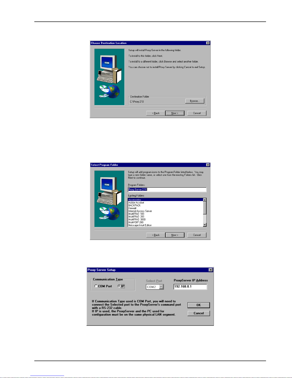
5. The Choose Destination Location dialog box is displayed. Follow the on-screen instructions to
install your ProxyServer software.
You can choose either the default destination by clicking Next > or click Browse to choose a
different destination folder for your ProxyServer software. Multi-Tech recommends that you
accept the default folder, C:\ProxyServer 2.10.
6. The Select Program Folder dialog box enables you to name the Program Folder for the
ProxyServer files. You can select the default name, ProxyServer 2.10, or name it anything you
like.
Click Next> to continue.
7. The ProxyServer Setup dialog box asks if you are configuring your ProxyServer through the
COM port of your PC or over the LAN (IP).
If you are configuring the ProxyServer over your network, click OK to continue.
If you need to configure your ProxyServer through the Command port, follow the instructions in
the dialog box for selecting the COM Port, then click OK to continue.
MTPSR1-202ST
19
Page 20
ProxyServer User Guide
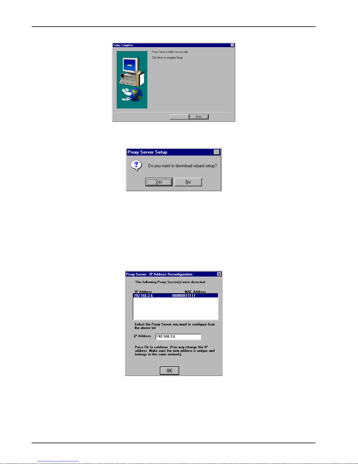
8. The Setup Complete dialog box is displayed.
Click Finish to continue.
9. The “Do you want to download wizard setup?” dialog is displayed.
The Wizard Setup screens enable you to input basic configuration information needed to
configure your ProxyServer. These screens guide you through the process of entering your LAN
address, Net Mask information and your WAN, DHCP Server, and Domain Name Server entries.
All entries display in their respective dialog boxes when accessed from the Main menu.
Click Yes to download the wizard setup; clicking No takes you to the program group (icons)
where you can choose any of eight ProxyServer utility programs.
10. If you are configuring your ProxyServer over the network, the IP Address Reconfiguration
dialog box is displayed showing the default IP and MAC addresses of all detected ProxyServers
in the top window and a suggested IP address in the lower window .
In the top window, select the ProxyServer you want to configure, then check the IP address in the
lower window.
The IP Address is only a proposed address. You must verify that this suggested address does
not conflict with the IP address of any other device currently on your network. If an address
conflict exists, change the contents of this field to assign a unique address to your ProxyServer.
Click OK when you are ready to continue.
20
MTPSR1-202ST
Page 21
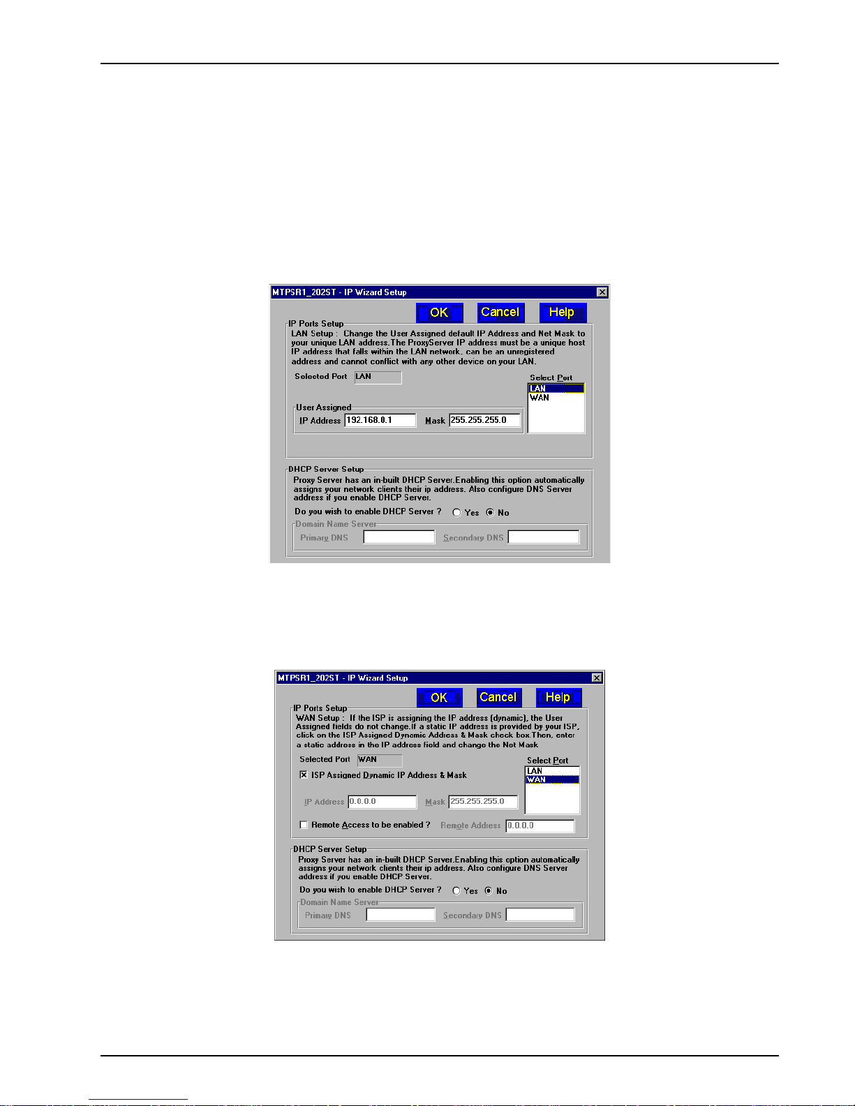
IP Wizard Setup
The IP Wizard Setup dialog box guides you through the process of assigning LAN and WAN IP ports
address information and provides an option to use the ProxyServer’s built-in DHCP Server if your
LAN is not already running a DHCP Server which automatically assigns client IP addresses. If you
choose to enable the built-in DHCP Server , you are given the option of also enabling the Domain
Name Server.
11. Follow on-screen instructions to configure the IP Ports, DHCP Server, and Domain Name Server.
Note: If you plan to use the ProxyServer’s DHCP server , disable any other DHCP server
operating on the local/private LAN to prevent clients from receiving IP addresses from two
independent sources.
Chapter 3 - Software Loading and Configuration
If necessary , obtain Primary and Secondary DNS IP addresses from the DNS tab under Network/
Protocol (or TCP/IP)/Properties or from your ISP.
Highlight the WAN option in the Select Port window to display W AN setup information.
12. The IP Wizard Setup dialog box displays the WAN setup information.
Follow the on-screen instructions to configure the WAN port. If you want the W AN port configured
for Remote Access, click the Remote Access to be enabled? check box and then enter the
remote IP address in the Remote Address field.
Click OK when you are satisifed with the IP Wizard Setup.
MTPSR1-202ST
21
Page 22
ProxyServer User Guide
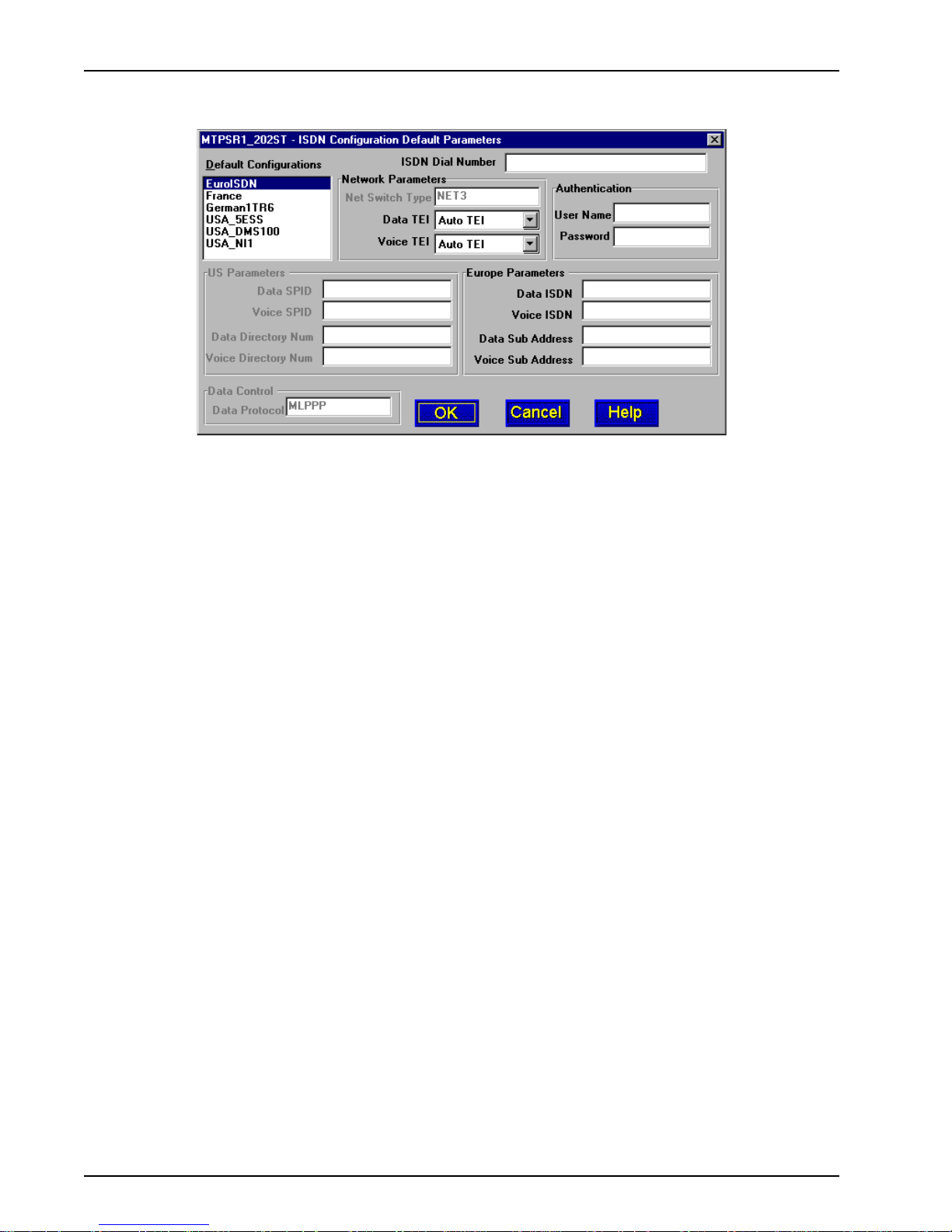
13. The ISDN Configuration Default Parameters dialog box is displayed.
In the Default Configurations window, click on the default configurations supplied by your local
ISDN service provider. Refer to your entry in Network Switch Type in Before You Start Loading
Your Software in this chapter.
14. Place your cursor in the ISDN Dial Number field and enter the telephone number supplied by
your Internet service provider. The telephone number can be a standard local number or it can
include a long distance prefix.
Note: Some Internet service providers require only that you enter the phone number you call for
ISDN service.
15. If the phone number is all your Internet service provider requires, click the OK button and go to
step 21 to continue loading your software. However, if your Internet service provider requires that
you enter additional parameters, continue with step 16.
16. Click the Data TEI field in the Network Parameters group. Refer to your Data TEI entry in the
Network Configuration section in Before You Start Loading Your Software. If the Data TEI is
different, click the drop-down list arrow and click the selection that corresponds to the Data TEI
supplied by Internet service (i.e., Disabled, Auto TEI, or zero to 63).
17. Click the Voice TEI field in the Network Parameters group. Refer to your Voice TEI entry in the
Network Configuration section in Before You Start Loading Your Software. If the V oice TEI is
different, click the drop-down list arrow, then click the selection that matches the Voice TEI
supplied by your Internet service (i.e., Disabled, Auto TEI, or zero to 63).
18. If your ISP or Remote Access Server (RAS) uses Point-to-Point Protocol (PPP), click the User
Name field in the Authentication group and enter your user name. If SLIP protocol is used by
your ISP or RAS, authentication is provided in script form.
19. If your ISP or RAS uses Point-to-Point Protocol (PPP), click the Password field in the
Authentication group and enter your password. If SLIP protocol is used by your ISP or RAS,
authentication is provided in script form.
20. Depending on your default configuration, the US Parameters group or the Europe Parameters
group will be active.
If the US Parameters group is active, enter the Data SPID supplied by your local phone
company which you recorded in Before You Start Loading Your Software.
21. Click the OK button to continue loading your software.
22
MTPSR1-202ST
Page 23

Chapter 3 - Software Loading and Configuration
22. The Checking ProxyServer dialog box is displayed.
The Setup utility is "Ready to Download wizard Setup”. Click OK to proceed.
23. The Writing Setup dialog box is displayed as the setup configuration is written to the
ProxyServer.
24. During the reboot, the Fail LED will be ON. Wait for the Fail LED to go OFF (approximately two
minutes).
25. Y ou are returned to the Multi-Tech Installation CD screen where you now have the option to
install (on your PC’s hard drive) Acrobat Reader (by clicking the Acrobat icon) and/or the User
Guide (by clicking the Install Manuals icon, selecting MTPSR1-202ST, and clicking OK). The files
will install at C:\Program Files\Multi-T ech Systems, Inc.\PSR1-202\Documentation unless you
browse and select an alternate directory for installation.
At this time your ProxyServer is operational. Verify that each client PC has an IP stack loaded,
workstation IP address assigned, gateway pointed to the ProxyServer, and the DNS name(s)
supplied by the ISP are entered. Refer to Chapter 5 for Client Setup information.
MTPSR1-202ST
23
Page 24
ProxyServer User Guide
Setting Up Your Remote User Database
The remote user database lets you enter information about your remote users. Each WAN port can
be configured as either a dial-out Proxy or a dial-in RAS. If you support remote dial-in, then the
remote user database needs to be created.
1. Win3.1 users - From the Program Manager, click the Remote User Data Base icon.
Win98/95 and WinNT users - From your desktop, click the Start button, point to Programs,
then ProxyServer 2.10, and then click Remote User Data Base.
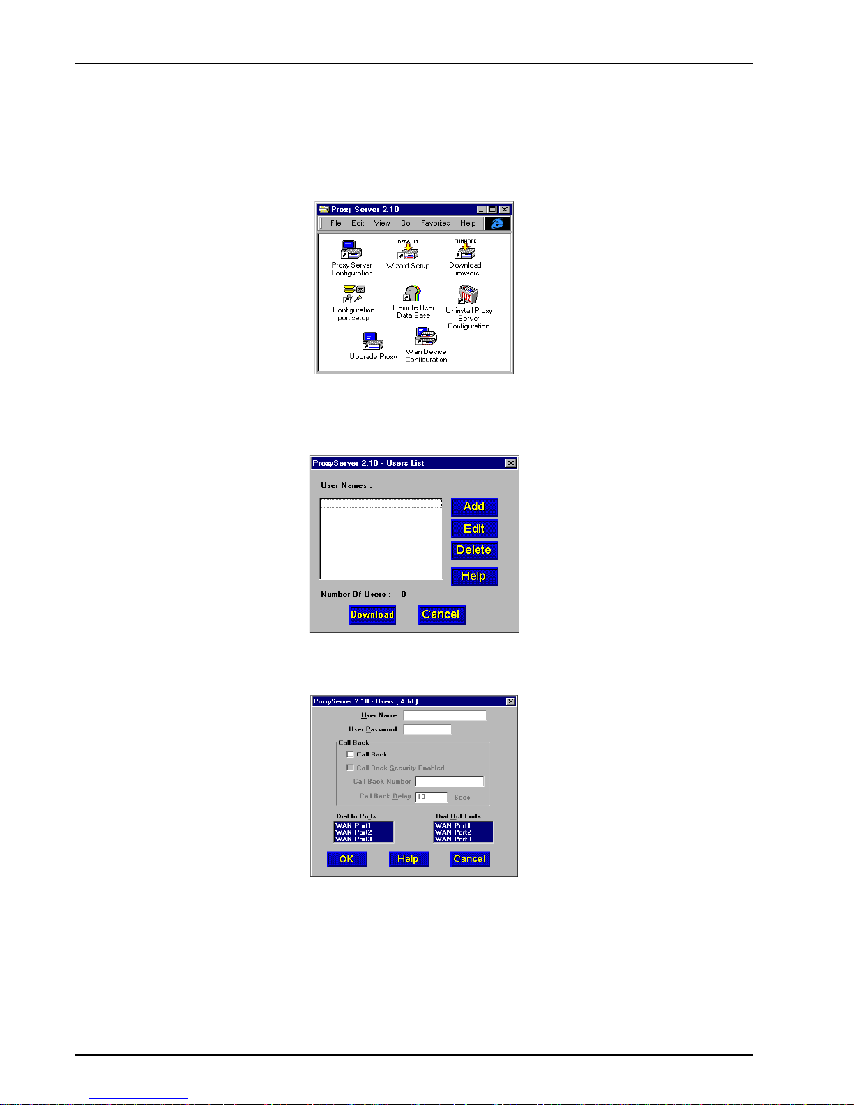
2. The Users List dialog box is displayed.
Click the Add button
3. The Add Users dialog box is displayed.
4. Build your user database by filling in the following fields for each user.
User Name.
The User Name can have as many as 39 characters. All printable characters are permitted with
the restriction that a blank cannot appear in the user name. The user name is treated as a case
insensitive string in dial-in and dial-out applications.
24
MTPSR1-202ST
Page 25

Chapter 3 - Software Loading and Configuration
User Password.
The User Password can have as many as 7 characters. In places where the password is used
as a character string, it is treated as a case insensitive string. Elsewhere (PPPs CHAP), it is
treated as a case sensitive pattern.
Call Back Security Enabled
This parameter is of use in dial-in applications where the user is required to be called back at a
specific location. Enabling this parameter results in having the administrator assigning the
callback parameters. Disable this if the user is to be permitted to choose the callback number
and callback delay .
Call Back Number
The callback number is editable only if callback security is enabled. This is the number where
the user will be called back. The user cannot choose the location where he wants to be called
back.
Call Back Delay
Call back delay is editable only if callback security is enabled. This specifies the duration after
which the user will be called back at the administrator-assigned number.
Dial In Ports
This allows you to select the port over which the user is permitted to dial into the ProxyServer.
Dial Out Ports
This allows you to select the port over which the user is permitted to dial out from the
ProxyServer.
5. As each user is defined in your database, click the OK button and the Users List dialog box is
displayed. Click the Add button to continue adding users to your database.
6. When you have added all your users to the data base, from the Users List dialog box, click the
Download button to load the database into the ProxyServer .
MTPSR1-202ST
25
Page 26

ProxyServer User Guide
26
MTPSR1-202ST
Page 27

Chapter 4 - ProxyServer Software
Page 28
ProxyServer User Guide
Introduction
This chapter describes the ProxyServer software and explains how to make changes to the
configuration of your ProxyServer. The major configuration parameters were established during
the loading of the software (Chapter 3). The ProxyServer software and configuration utilities allow
you to make changes to that initial configuration.
The ProxyServer software allows you to refine your configuration based on your network
connections. The software is based on a main menu (Proxy Setup) that allows you to consider all
the parameters for a particular feature (e.g., Internet access, DHCP Server addressing, and
Virtual Server mapping). These features, along with others are discussed in detail in the
ProxyServer Configuration section later in this chapter.
The other five configuration utilities offer additional functionality. Wizard Setup guides you
through the initial configuration and software downloading, as described in Chapter 3. Download
Firmware allows you to download new versions of firmware when enhancements become
available. The Configuration Port Setup utility allows you to change the method by which you
access the ProxyServer (i.e., direct connection of a PC to the Command Port on the ProxyServer,
or via your network connection to the LAN port on the ProxyServer). The Uninstall ProxyServer
Configuration utility is designed to remove the software from your PC. The WAN Device
Configuration utility will open the Print Console, a terminal emulation program that will enable
you to configure any external devices connected to the WAN ports. The Remote User Data Base
option allows you to enter information regarding your remote users; and, the Upgrade Proxy
feature allows you to download software updates from Multi-Tech System’s FTP site.
Note: The WAN Device Configuration utility is only supported if you are directly connected to
the ProxyServer. This Utility is not supported when accessing the ProxyServer via the network.
Your ProxyServer software includes the ProxyServer on-line Help system. The Help is designed
to be context sensitive. Clicking the Help button within a given dialog will provide definitions and
recommended values for each button, option, and field for that dialog. In some instances, you will
also be presented with a list of related topics that can be displayed by clicking the green,
underlined text. In addition, you can search the entire Help system (via the Index tab) for
definitions and references to specific terms, fields, and recommended values where applicable.
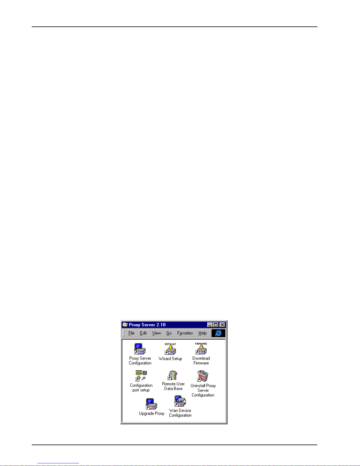
Before You Begin
The ProxyServer software operates in a Microsoft Windows environment. Your ProxyServer
program group contains all of the utilities described above, and is accessible in Windows by
clicking Start | Programs | ProxyServer 2.10 | (utility), or by double-clicking the utility icon in the
program group in My Computer. The program group is shown here:
28
MTPSR1-202ST
Page 29
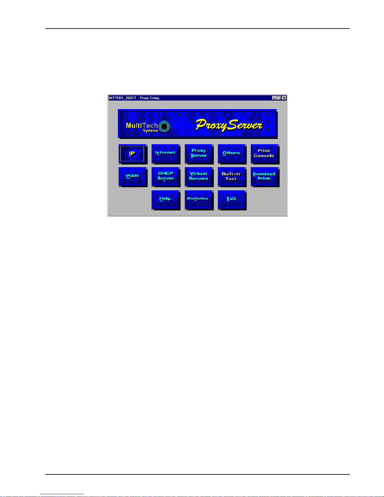
Proxy Setup
All changes to your ProxyServer configuration are initiated through the Proxy Setup dialog box or
Main menu. To view or change your ProxyServer configuration in Windows 98/95 and Windows NT,
click Start | Programs | ProxyServer 2.10 | ProxyServer Configuration. You can also start the
ProxyServer Configuration from My Computer by double-clicking the Proxy.210 folder on your local
drive, then double-clicking on the Roucon.exe file. After loading, the Proxy Setup menu will appear.
Chapter 4 - ProxyServer Software
The Proxy Setup menu consists of 13 buttons, eleven of which allow you to display and change the
IP settings, define the WAN ports, change features such as the Internet, DHCP Server, ProxyServer,
and virtual Servers, display WAN port Statistics, control activation of Telnet, TFTP, and WEB servers
and dumb terminal management, test the communications link, print messages received from the
target ProxyServer, and download setup information to the ProxyServer.
The two outer buttons in the bottom row enable you to open the on-line Help system and end (Exit) a
Proxy configuration session.
Note: Pressing the Built-In T est button displays the Diagnostics dialog box which allows you to
perform certain hardware tests on the LAN and WAN links. The Print Console option brings up the
console terminal that displays any print message received from the ProxyServer.
MTPSR1-202ST
29
Page 30
ProxyServer User Guide
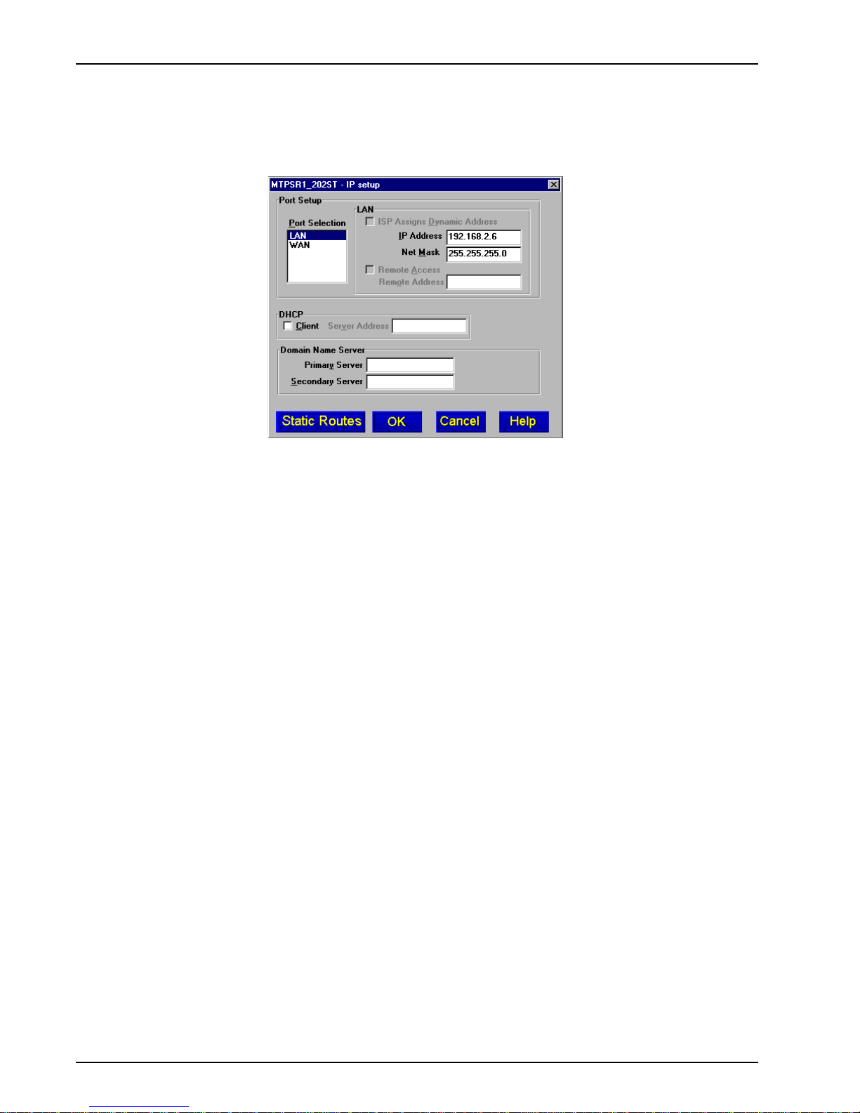
Changing IP Parameters
The IP Setup dialog box displays the IP addressing for your LAN and W AN ports that were
established during your initial configuration. The IP Setup dialog box allows you to change any of the
original parameters.
The IP Setup dialog box displays the unique LAN address and net mask you established during your
initial configuration. If you are using your ProxyServer in an Internet application with one or more of
the WAN ports connected to the Internet and your ISP is dynamically assigning addresses to those
WAN ports, then you will want to leave the ISP Assigns Dynamic Address option active.
If you wanted to change a WAN port to support a static IP address, you would select the WAN port
and disable the ISP Assigns Dynamic Address option. This activates the IP Address and Net Mask
fields for that WAN port. You then need to enter a static IP address in the IP Address field and
assign an appropriate net mask in the Net Mask field. Then you would want to check the WAN Setup
dialog box and establish the Port Type for the selected WAN port, e.g., if the WAN port is being used
for remote access, you would want to enable the RAS Enable option; if the port is being used as a
dial in feature, you would want to enable the Dial in Only option in the Port T ype group.
If you wanted to change a WAN port to dial out to a telephone number other than the Internet, you
would select the WAN port and disable the ISP Assigns Dynamic Address option. This activates
the IP Address and Net Mask fields for that WAN port. You then need to enter a WAN port IP address
in the IP Address field and assign an appropriate net mask in the Net Mask field. You would then
need to check the WAN Setup dialog box and change the Port Type for the selected WAN port to
enable the Dial Out option and enable the Asynchronous Gateway (AG Enable) option.
If you wanted to change a WAN port to be available for remote access, you would select the WAN
port and disable the ISP Assigns Dynamic Address option. This activates the IP Address and Net
Mask fields for that WAN port. You then need to enter a WAN port IP address in the IP Address field
and assign an appropriate net mask in the Net Mask field. You would then need to check the WAN
Setup dialog box and change the Port T ype for the selected WAN port to enable the Dial In option
and enable the Remote Access Server (RAS Enable) option.
The DHCP (Dynamic Host Configuration Protocol) group allows IP addresses to be assigned by a
DHCP Server . In such cases, a PPP client connected to the WAN port will be on the same IP network
as the LAN port. Because the DHCP Server automatically assigns an IP Address for a PPP client
coming up on a “Client Only” WAN port, this feature can save IP addresses that otherwise would have
been taken up by the WAN port.
To enable DHCP, you must check the Client box and enter the IP address of the external DHCP
Server (e.g., Microsoft’s DHCP feature) in the Server Address field. The Server Address is assigned
by your systems administrator.
30
MTPSR1-202ST
Page 31
Chapter 4 - ProxyServer Software
The Domain Name Server (DNS) group is used to resolve Fully Qualified Domain Names (FQDN) to
an IP address. This field can either be filled in or left blank. If it is left blank, your ISP will assign a
DNS address. This DNS address will also be handed off to any client obtaining an IP address from
the ProxyServer’s DHCP Server.
The Primary Server field defines the IP address of the first host that the ProxyServer will attempt to
connect to upon a user request. If this server is unavailable, the ProxyServer will attempt a
connection with the Secondary Server (if defined). The Secondary Server field defines the IP
address of the DNS server for cases where the primary server is unavailable.
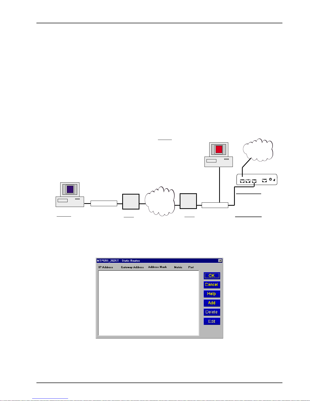
The Static Routes feature allows a remote client PC access to the Internet through a pre-defined
route (static route). Static routing is normally used when a part of an internetwork can only be
reached by one particular path. Static routes are manually configured routes that specify the
transmission path a data packet must follow based on the data packet’s destination address. In the
example below, a data packet sent from the remote client PC to access the remote Internet through
the MTPSR1-202ST must have IP Address 200.1.1.0 and Gateway Address 192.168.2.1 (entered as
the Static Route configuration). This determines the return path the data packet will take back to the
client PC.
Client PC
Remote Network
Client PC
IP Address - 200.1.1.10
Subnet mask - 255.255.255.0
Default Gateway - 200.1.1.1
Hub
Local PC
IP Address - 192.168.2.10
Subnet mask - 255.255.255.0
Default Gateway - 192.168.2.6
T1,
Frame Relay,
Router
Router
IP Address - 200.1.1.1
Subnet mask - 255.255.255.0
WAN Local - 200.2.10.2
WAN Remote - 200.2.10.1
V.90/K56Flex,
ISDN
Router
Router
IP Address - 192.168.2.1
Subnet mask - 255.255.255.0
WAN Local - 200.2.10.1
WAN Remote - 200.2.10.2
Default Gateway - 192.168.2.6
Local PC
Hub
Internet
MTPSR1-202ST
10BASE T
COMMAND
PHONE
ISDN
MTPSR1-202ST
IP Address - 192.168.2.6
Subnet mask - 255.255.255.0
Static Routes
IP Address - 200.1.1.0
Gateway Address - 192.168.2.1
Address Mask - 255.255.255.0
Metric - 1
Port - LAN
From the IP Setup dialog box, click the Static Routes button to display the Static Routes dialog
box.
POWER
ON
OFF
Click Add to display the Static Routes Setup dialog box where you can configure a new static route.
Note: You can also edit or delete static routes by clicking the Edit or Delete buttons.
MTPSR1-202ST
31
Page 32

ProxyServer User Guide
The Static Routes Setup dialog box is displayed. Select and key in the appropriate information for
setting up the static route.
Port is the type of port, usually LAN (If you have a modem connected to the WAN port and are using
it for RAS, you could set up a static route to route incoming traffic to a different network). The IP
Address must be the address of the target host or network in the static route (In our example, Static
Route IP Address 200.1.1.0 indicates that PC clients on Routers with IP addresses beginning with
200.1.1 will be included on the static route). The Address Mask is the IP subnetwork mask
(255.255.255.0) of the target host. The Gateway Address must be the IP address of the local router
(Gateway Address 192.168.2.1) on the next hop toward the target host and the port (i.e., LAN) with
which it is associated. Metric is the hop count (1) to the target host.
Once you have completed entering all the appropriate information, click OK. The static route is
entered in the Static Routes table.
32
MTPSR1-202ST
Page 33

Changing WAN Port Parameters
The ProxyServer is designed to provide the flexibility needed to meet today’s application needs. The
WAN Setup dialog provides the controls for WAN configuration. The basic controls offered in the
Mode and Connection Method groups are described in detail in your on-line Help system. The Link
Control (Dial-on-demand) and Advanced tab are discussed in some detail.
Chapter 4 - ProxyServer Software
The Link Control group allows you to control the conditions and parameters of the traffic on the
WAN port. Using the Enable and Idle Time features, you can cause the ProxyServer to drop the
connection on the selected WAN port after a specified duration without activity (as defined in the Idle
Time field). The default setting is enabled (checked) with an idle time of 10 minutes. If you do not
wish to use this option, click to disable (uncheck) it.
The Port T ype group (in the WAN Setup dialog) is used to configure the ports for specific
applications. The default settings for this group are Dial Out only and Proxy Enable.
This default setting works if you are setting up the WAN port to communicate with the Internet. If this
is the case, the WAN port must be enabled and the Port Type group configured for Dial Out Only or
Dial Out/In and the Proxy Enable option selected. As mentioned earlier, the Internet Setup dialog
box is used to configure the Internet Link Control Protocol, i.e., call connection and handshaking.
The Asynchronous Gateway (AG Enable) feature can be used on WAN ports configured as Dial Out
only or Dial Out/In. This feature is used to enable the ProxyServer to have a port available for a
remote user running a communications package to gain access to an available port on the
ProxyServer and dial out. When you enable this feature the Asynchronous Gateway group (at the
bottom of the dialog) becomes active. Refer to the on-line Helps for a description of features in this
group.
The WAN ports can also be configured for remote access (RAS Enable) with either the Dial In Only
or Dial Out/In option enabled. If enabled, you must enable Remote Access and enter the WAN port
IP address in the IP Setup dialog box. This ensures that the selected WAN port and the Remote
Address assigned to it are in the same LAN segment. The remote IP address is assigned to the
remote user.
MTPSR1-202ST
33
Page 34

ProxyServer User Guide
From the Advanced tab, you can change the parameter configurations for the type of Message
Printing, determine when to enable Script Printing, and define the Switch T ype providing the ISDN
connection.
In the Configuration T ypes window, select the appropriate configuration (e.g., USA_DMS100) and
click Edit. The Parameter Configuration dialog box is displayed.
This dialog box displays the network switch type and the US Parameters or the Europe Parameters,
depending on the switch type selected. In the first example (above), the default US Parameters are
displayed and are available for editing purposes. The uppermost text box (USA_DMS10) on the
dialog box is not available for editing as it is used only for adding the names of new parameter
configurations. The Net Switch Type is also unavailable as it is the switch type that was defined for
this particular configuration.
General Parameters
Data TEI (Terminal Endpoint Identifier) - You may have received a fixed TEI (a number from 0 to 63)
from your provider; if so, then select that number from the list in the Data TEI box. However , if the
central office switch assigns a dynamic TEI each time your ProxyServer connects to the network,
then leave it set to the default, “Auto TEI.” If you have multiple ProxyServers attached to a network
terminator bus, you may want to set the Data TEI to ”Disabled.”
V oice TEI - Y ou may have received a fixed TEI (a number from 0 to 63) from your provider; if so, then
select that number from the list in the Voice TEI box. However, if the central office switch assigns a
TEI each time your ProxyServer connects to the network, then leave it set to “Auto TEI.” Again, if
you have multiple ProxyServers attached to a network terminator bus, you may want to set the Voice
TEI to “Disabled.”
34
MTPSR1-202ST
Page 35

Chapter 4 - ProxyServer Software
US Parameters
The US Parameters group includes the Data SPID, Voice SPID, the data Directory Number (DN),
and the voice DN. The SPIDs and Directory Numbers may not be required by your service provider;
but, if they are required, the fields are defined below.
Data SPID (Service Profile Identifier) - Enter the Data SPID, if required, that was assigned by the
local phone company for the specific BRI line to which the ProxyServer is attached. The Data SPID
string can have up to 20 characters. For DMS-100 switches, any ASCII character except the
underline (_) is valid; For NI-1 and AT&T switches, only the digits 0-9 are valid.
V oice SPID - Enter the Voice SPID, if required, that was assigned by the local phone company for
the specific BRI line to which the ProxyServer is attached. The V oice SPID string can have up to 20
characters. For DMS-100 switches, any ASCII character except the underline (_) is valid; For NI-1
and AT&T switches, only the digits 0-9 are valid.
Data Directory Number (DN) - The data DN is a telephone number the ISDN service provider
assigns, if required, to the ProxyServer at subscription time; this can be a string of up to 24
characters. V alid characters are 0-9, the * character, and the # character.
V oice DN - The voice DN is a telephone number the ISDN service provider assigns, if required, to the
ProxyServer at subscription time; this can be a string of up to 24 characters. V alid characters are 0-9,
the * character, and the # character.
European Parameters
The Europe Parameters group includes the Data ISDN, Voice ISDN, the Data Sub Address, and the
voice Sub Address. The Data and Voice ISDNs and Sub Addresses may not be required by your
service provider. If the ISDNs and Sub Addresses are required, the fields are defined below.
Data ISDN - Enter the Data ISDN, if required, that was assigned by the local phone company for the
specific BRI line to which the ProxyServer is attached. The Data ISDN string can have up to 20
characters. If the switch type is NET3, the Data ISDN is not used.
V oice ISDN - Enter the Voice ISDN, if required, that was assigned by the local phone company for the
specific BRI line to which the ProxyServer is attached. The V oice ISDN string can have up to 20
characters. If the switch type is NET3, the Voice ISDN is not used.
Data Sub Address - The Data Sub Address is a telephone number the ISDN service provider
assigns, if required, to the ProxyServer at subscription time; this can be a string of up to 24
characters. V alid characters are 0-9, the * character, and the # character.
V oice Sub Address - The Voice Sub Address is a telephone number the ISDN service provider
assigns, if required, to the ProxyServer at subscription time; this can be a string of up to 24
characters. V alid characters are 0-9, the * character, and the # character.
MTPSR1-202ST
35
Page 36

ProxyServer User Guide
Call Control Parameters
Persistent DTR Dialing - Data Terminal Ready (DTR) normally goes high when a communication
program starts or is ready to dial. A high DTR on the serial port indicates that your computer or
terminal is ready to communicate with the ProxyServer. The Persistent DTR Dialing function built into
the ProxyServer enables the ProxyServer to automatically redial the telephone number of the ISDN
service provider whenever DTR is high and there is no active call on the serial port. You can either
enable or disable this feature (the default for this function is “disabled” or unchecked).
Note: You can use the key combination, “Alt-P” to check or uncheck this function.
Calling Line Identification (CLI) - When you check this function, the ProxyServer identifies (for
ISDN data calls only) whether the two endpoints of a connection are enabled or disabled for the
purposes of RING messages. If the Calling Party Number is included in the incoming SETUP
message for a given call, the RING message will display it, together with the Called Party Number, in
the following format: “FM: 5552000 TO: 5551000.” If the Called Party Number is not included in the
SETUP message, the RING message will show only the Calling Party Number as follows: “FM:
5552000.” If neither number is included, the RING message will contain no additional information.
The default for this parameter is “enabled” or checked. Note: you can use the key combination
“Alt-D” to check or uncheck this function.
Auto Protocol Detection - You should leave this function disabled (unchecked) because we set the
Data Protocol in the Data Control group to “MLPPP” and do not use any of the other protocols listed
there.
Auto Answer Data Calls - You can enable this function if you want your ProxyServer to answer
automatically all incoming data calls (this option does not affect the analog port). If you do enable the
Auto Answer function, you should also set the Rings To Answer function unless you want to leave it at
the default selection which is one ring before it answers. (Selecting either “0” or “1” causes it to
answer after the first ring.)
Data Control
Data Protocol - As mentioned above (in Auto Protocol Detection), we leave this function set to
MLPPP, which uses both B channels (each at rates of up to 64 Kbps per channel) providing an
aggregate data transmission speed of 128 Kbps, maximum.
Data Compression - You should leave this function set to the default, which is “None.”
Dialing Method - The default is “Enbloc,” which is used for most ISDN dialing; however, if your
ProxyServer is on a private network you can switch to the “Overlap” dialing method for establishing a
data call on the ISDN line.
36
MTPSR1-202ST
Page 37

Internet Setup
The Internet Setup dialog box displays the phone number the ProxyServer is going to dial to reach
your ISP, the protocol the ISP supports, and if you would link the ProxyServer to dial a telephone
when you power on your unit.
Chapter 4 - ProxyServer Software
The Dial Number field displays the phone number of the ISP you initially assigned during your initial
configuration. If the WAN port is not being used for Internet access, then the Dial Number field should
be blank.
ProxyServer supports Point-to-Point Protocol (PPP) and Serial Line Internet Protocol (SLIP) on the
WAN link. The majority of the time the ISP is going to support PPP. PPP supports two user
authentication protocols; Password Authentication Protocol (PAP) and Challenge Handshake
Authentication Protocol (CHAP). When you established your Internet account your ISP should have
indicated which protocol it supports.
Your user name and password are displayed in the PPP group for the WAN port which will be
connected to the Internet. The user name and password were enterred in the Default WAN Link
setup dialog box during the initial configuration. If the WAN port is not being used for Internet access,
then the User Name and Password fields will be blank. You can change your User Name and
Password in these fields for the WAN port.
Clicking the Advanced tab brings up the parameters that affect the WAN link.
MTPSR1-202ST
37
Page 38

ProxyServer User Guide
The Message Printing Control group is used to flag specific items for generating messages on
various conditions, including Printing, Alarm, NCP (NetWare Core Protocol), and LCP (Link Control
Protocol) messages. These messages can be useful as troubleshooting tools; however , it is
recommended that under normal circumstances all items should be disabled to avoid degradation of
ProxyServer performance.
If the Need to dial out initially option is enabled (default) the ProxyServer will dial the phone
number entered in the Dial Number window upon start up. If this option is disabled, then the
ProxyServer will wait to dial until the first dial request has been made.
The Echo Request group allows you to configure the Link Control Protocol (LCP) Echo Request
parameters. Options include Maximum Number of unacknowledged LCP Echo requests allowed
before triggering the termination of the link to the peer (valid range is 1 to 20 with a default of 6
requests) and Send Interval defines the interval that the LCP will insert between two consecutive
LCP Echo Requests (valid range is 0 to 65535 with a default 0 seconds).
The Termination Request group allows you to configure the Link Control Protocol (LCP) Termination
Request parameters. Options include Maximum Number of LCP Termination Requests issued after
the completion of a back-off interval (valid range is 1 to 20 with a default of 10 requests); and, Send
Interval Max defining the interval that the LCP will insert between two consecutive LCP Termination
Requests (valid range is 5 to 65535 with a default of 5 seconds).
The Configurations Requests group allows you to configure the Link Control Protocol (LCP)
Configuration Request parameters. Options include Maximum Number of requests to be sent before
backing off due to no response (valid range is 3 to 65535 with a default setting of 6 requests); Send
Interval Max defining the interval between two consecutive LCP configuration requests (valid range is
5 to 65535 with a default of 5 seconds); and, Backoff Interval defining the interval that the LCP will
insert once the unanswered Maximum Number of Configuration requests has been reached (valid
range is 5 to 65535 with a default of 5 seconds).
38
MTPSR1-202ST
Page 39
Enabling the DHCP Server
The Multi-Tech DHCP (Dynamic Host Configuration Protocol) server feature manages all IP address
assignments within a local/private LAN. The DHCP Server maintains a list of available IP addresses
and when a client computer asks for one, the DHCP Server sends the IP Address to the client. The
client computer, configured with that information, can then participate in the TCP/IP network.
What are the advantages of DHCP? Why not let your systems administrator assign permanent IP
addresses? Because DHCP assigns IP addresses only to computers that are active on a TCP/IP
network, non-active computers do not need to reserve an IP address. This helps workgroups that
have limited numbers of IP addresses. DHCP also simplifies the process of setting up clients. Instead
of having to remember which IP addresses you’ve assigned and which addresses are free, you can
simply configure the client for DHCP and let the DHCP server do the rest (Refer to Chapter 5 - Client
Setup).
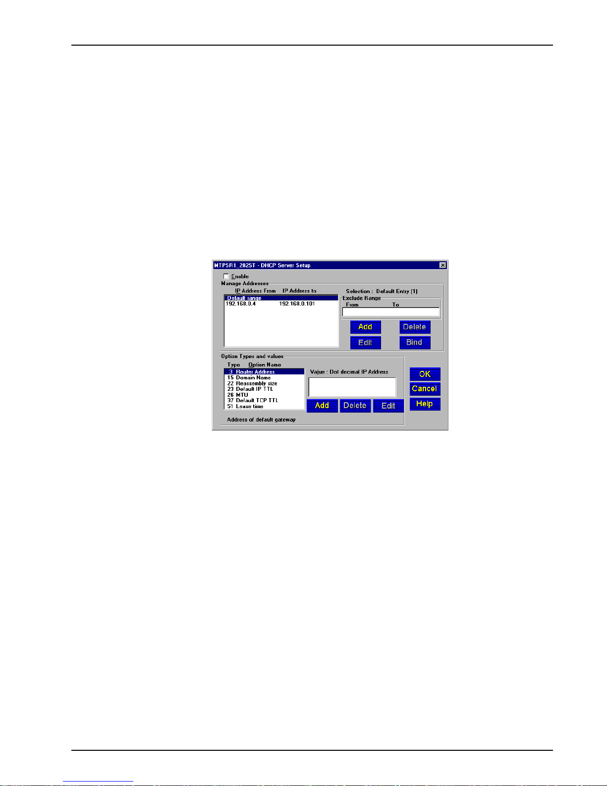
To display the DHCP Server Setup dialog box, click the DHCP Server button on the Proxy Setup
menu. To enable the DHCP Server, click (check) the Enable option and make appropriate choices.
Chapter 4 - ProxyServer Software
The DHCP Server Setup menu allows you to customize each client PC configuration from one
central point. The Manage Addresses group allows you to establish the range of IP addresses for
the workgroup (From - To). You can then exclude specific addresses from that range in the Exclude
Range field. Excluded addresses (individual IP addresses or a range of addresses) are computers
with static IP addresses (e.g., a DNS server , a WINS server, and the DHCP server itself). You can
also add, delete, edit, and bind addresses using the corresponding buttons in this group.
The Option Types and Values group at the bottom of the dialog box allows you to customize the
configuration of the client platform. You can add, delete, and edit an option by highlighting it and clicking the appropriate button. You cannot, however, edit or delete entries provided in the default list.
This group includes the Router Address which is the location on the IP subnet that a client can use;
the Domain Name which is the human-readable Internet name of your IP domain; the Reassembly
size which sets a maximum datagram reassembly size; the Default IP TTL which sets the IP time-tolive limit (max. 255); the MTU (Maximum Transmit Unit) which sets the largest possible unit of data
that can be sent; the Default TCP TTL which sets the TCP time-to-live limit; and the Lease time
option which sets the time duration that an IP address is assigned to a client.
When a client requests an IP address, it is given that address for a specific duration of time. Once the
time duration has expired, the client must have received an extension on the lease or received
another IP address to use. The default lease is 65535 seconds (18.2 hours). Assigning lease time
depends on your goals and the site’s usage patterns. For example, if you have more users than IP
addresses, a shorter lease (hours) would be appropriate; however, if students at a university have
their computers turned off for a long period of time (and you want them to keep their IP addresses),
then a longer lease (weeks) would be appropriate.
MTPSR1-202ST
39
Page 40

ProxyServer User Guide
Adding ProxyServer Applications
The Proxy Applications configuration dialog box allows the ProxyServer systems administrator to
configure the set of applications available for proxying by the ProxyServer.
Click the ProxyServer button in the Proxy Setup menu to display the Proxy Applications
configuration dialog box which lists all the applications currently supported by the ProxyServer. This
list includes many of the most common port usages; however, not all are included because an
increase in the number of port usages supported means a possible decrease in performance speed
and an increased security risk.
Use the Add/Edit Entry dialog box to add or edit ProxyServer applications. For procedural details,
refer to the ProxyServer Help.
The option to add ProxyServer applications is important as new software programs are continually
being developed to perform useful tasks. For example, you may want to add new database
managers, spreadsheets, communications packages, graphics programs, etc., anything that would
make your job easier.
Editing considerations might mean enabling/disabling protocols (both TCP and UDP are enabled by
default), changing the ProxyServer description (to be more easily identified), or changing the range of
port numbers to exclude/include other users (refer to the ProxyServer Help for details).
You must first determine which currently unsupported applications can be proxied. You can refer to
RFC 1700 on the Internet which defines the Internet Protocol suite. RFC 1700 identifies the
parameters, such as Internet address, domain names, autonomous system numbers, protocol
numbers, port numbers, and many others. Once the necessary information has been determined,
you can add the application(s) to the supported list. Without this information, the Proxy will not allow
packets through to the Internet from the unknown software.
40
MTPSR1-202ST
Page 41
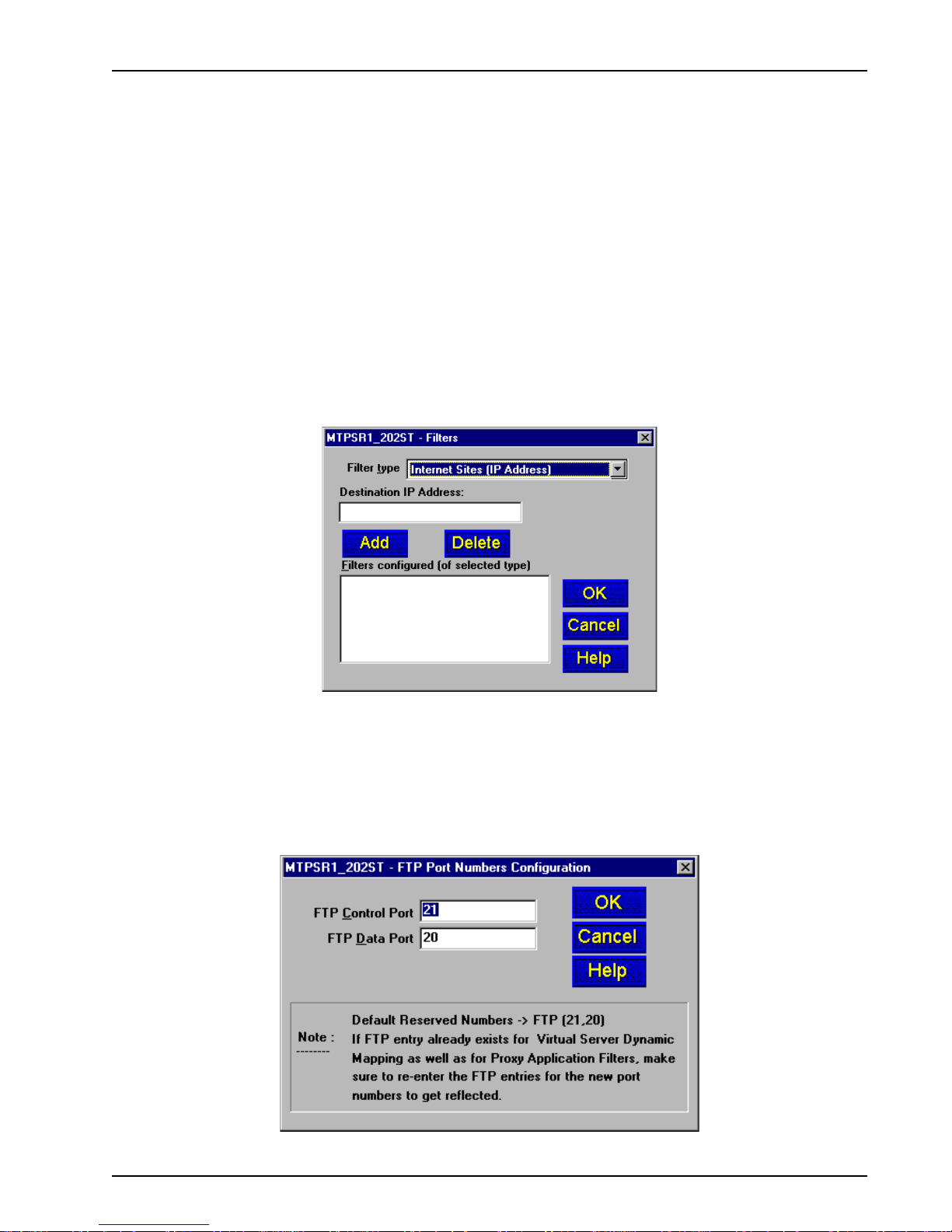
Chapter 4 - ProxyServer Software
The ProxyServer administrator can set up “filters” on the proxy server for better control. The Filter
option can be used when you want to block all packets originating from a specific destination (called
source address filtering) or all packets heading for a particular destination (called destination address
filtering). Filters can be set to exclude packets of a particular protocol or any particular field in a LAN
packet.
These filters are based on three basic filter types: Internet Sites (IP Address) (both dotted decimal
and Domain Name), Client Workstation (MAC address or IP address), or Application. To install a
filter, you must first choose one of these basic filter types. Refer to the ProxyServer Help for details
on how to configure the Filter option.
For example, in a filter set up by Domain Name, the system administrator could restrict all users at a
particular site from accessing game sites, X-rated sites, etcetera; or, users at a particular MAC
address or IP address could be restricted from using the services of the ProxyServer; or, you could
restrict all users from accessing specific applications (e.g., FTP, chat, etcetera).
Note: The Filter option does not perform content filtering; rather, the system administrator needs to
restrict users from the particular Internet site, client workstation, or application through the Filters
dialog box.
Note: Adding applications may decrease performance speed and increase security risks. Therefore,
you may want to delete unused or rarely used applications.
To further enhance the security of the firewall network, the FTP button on the Proxy Applications
configuration dialog box allows you to change the FTP Control Port and Data Port Numbers. If you
do change these numbers, make certain that you inform users who need to access the FTP server
what the new numbers are. By default, the FTP server’s Control Port Number is 21 and the Data Port
Number is 20.
MTPSR1-202ST
41
Page 42
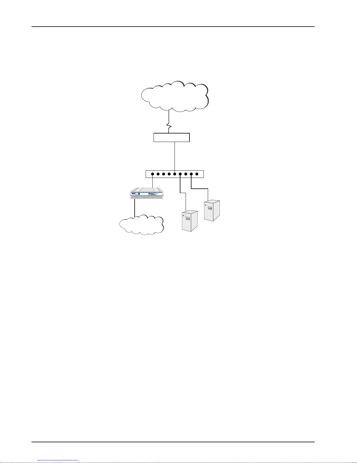
ProxyServer User Guide
Enabling the Virtual Server
The virtual server feature of the ProxyServer allows you to have multiple servers on your local area
network (LAN) with one static IP address (from your ISP or Multi-Tech’s Global Dynamic WAN
Addressing) assigned to the WAN port. A normal internet connection requires a static IP address for
each server on your LAN. A normal Internet connection is shown in the following illustration.
Internet
Router
Hub
Firewall
204.111.2.60
Secure
LAN
Web Server
204.111.2.30
FTP Server
204.111.2.20
In a normal Internet connection with a router connected to the Internet, you need a static IP address
for each function (server) you want to perform on the Internet. For example, to have a Web server
browse the internet for you, you need an IP address so that the router knows where the traffic is
coming from and where to send the reply . In our normal Internet connection we have assigned an
address of 204.111.2.30 for the Web server, address 204.111.2.20 for the FTP server, and
204.1 11.2.60 for the Firewall.
To reduce the number of static IP addresses, the ProxyServer’s virtual enable feature allows you to
map multiple local servers to a single static IP address or to a Global Dynamic WAN port address.
The virtual server feature enables the ProxyServer to take requests from different servers (functions)
and interact with the Internet based on the functionality of the request. In the normal Internet
connection, this was a physical linkage to a specific IP address. The virtual server feature is a
functional connection. Functionality is defined by how the server is used; i.e., the Web server uses a
www-http protocol, an e-mail server uses pop-3 and SMTP protocol. Therefore, multiple requests
can be sent to the Internet over a single physical connection and the ProxyServer will know which
server is requesting service. The following illustration shows how a ProxyServer is connected to the
Internet with a single static IP address or Global Dynamic WAN port address and the same servers
used in the normal Internet connection are now connected to the Internet through the ProxyServer.
Now, if instead of mapping a static IP address from your ISP to the ProxyServer, you employed MultiTech’s Global Dynamic WAN port addressing method, you no longer have to be concerned with a
single static IP address from your ISP. Y ou can assign a predefined Global Dynamic WAN port
address to each of the ProxyServer’s WAN ports and then map your servers to that WAN port
address the same way you would map a static IP address from your ISP. The predefined Global
Dynamic WAN port addressing scheme is 0.0.0.1 for the W AN port.
42
MTPSR1-202ST
Page 43
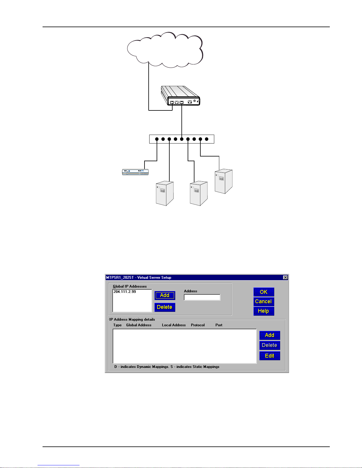
Internet
Chapter 4 - ProxyServer Software
WAN Port
Static IP Address
204.111.2.99
COMMAND
PHONE
ISDN
10BASE T
POWER
MTPSR1-202ST
ON
OFF
Secure IP Address
192.168.11.10
Hub
Voice / Fax over IP Networks
MultiVOIP
192.168.11.50
Q931
RTCP (5005,7)
RTP (5004,6)
(UDP Only)
E-Mail Server
192.168.11.40
POP-3 (110)
SMTP (25)
Web Server
192.168.11.30
WWW (80)
FTP Server
192.168.11.20
FTP (20,21)
The Virtual Server Setup dialog box defines how the servers are connected to the one global IP
address. The static IP address that we established in our virtual server connection example above is
added to the Global IP Addresses group in the Virtual Server setup dialog box. This could also be a
Global Dynamic WAN address.
With static IP addressing, the Global Ip Address is the IP address that is seen by the Internet. This
global address will be used by the virtual server feature to filter the activity of the traffic to and from
the Internet by functionality . The addresses that we assigned to our servers in the virtual server
example are unregistered addresses that are only seen by the ProxyServer. These local IP
addresses are arbitrarily assigned to servers in our virtual server connection example. For example,
we assigned IP address of 192.168.11.20 to the FTP server, 192.168.11.30 to the Web server,
192.168.1 1.40 to the e-mail server, and 192.168.11.50 to the MultiVOIP.
MTPSR1-202ST
43
Page 44

ProxyServer User Guide
These local addresses are then mapped to the global address by function. The FTP server was
assigned an IP address of 192.168.11.20 with a TCP and UDP protocol and a port number of 20 and
21. The Mapping Details [Local] group in the Virtual Server Mappings dialog contains the FTP
server local mapping information. When the FTP server mapping information is entered, the Web
server can be mapped to the global address by entering the IP address 192.168.11.30 in the Local IP
Address field of the Mapping Details [Local] group with its protocol and port information. Then the
mail server, and if a MultiVOIP is used in the local network - its mapping information, can be added to
the local mapping group.
The Virtual Server Setup dialog displays all the local mapping information.
44
MTPSR1-202ST
Page 45

Enabling Remote Servers
The Applications Setup dialog box lets you set up support for Telnet Server, TFTP (Trivial File
Transfer Protocol), WEB Server, and Dumb Terminal Management in the ProxyServer.
Telnet/TFTP
Telnet is an applications level protocol commonly found in IP-based networks that allows terminal
emulation at a remote workstation. To do this, there is usually a server at a central point that allows
multiple clients to connect and request to use the service. The service could be anything. Usually it is
terminal emulation. The ProxyServer has a Telnet server that allows multiple clients to connect and
request to use Telnet service, usually terminal emulation. T elnet is most often implemented over TCP.
TFTP is a file transfer protocol that uses UDP and provides a simple method for transferring files
between two nodes (the server and the client).
To display the Applications Setup dialog box, click Others on the Proxy Setup main menu.
Chapter 4 - ProxyServer Software
WEB Server
The WEB Server interface allows you to configure the ProxyServer remotely through your Web
browser on your local network. Enter the IP address of the ProxyServer in the Location (Address)
field of your browser to launch the Multi-Tech ProxyServer Configuration site.
By scrolling down the browser scroll bar, you are presented with a link to log in to the ProxyServer
configuration menu (“Click Here to Login”), as well as links to Multi-Tech’s WWW site, FTP site, and
Tech Support site.
MTPSR1-202ST
45
Page 46

ProxyServer User Guide
Click the word “Login” to launch the ProxyServer Configuration program. The Enter Network
Password dialog box is displayed.
Type the term “supervisor” in the User Name field (no password is needed) and click OK.
The Proxy Server Configuration menu is displayed.
The Proxy Server Configuration menu provides several categories: Protocol Stacks, Device
Drivers, Other Setup, and Statistics for the WAN port. Each category provides links which allow
configuration of various features. Click the item you need to configure and the program displays a
configuration dialog box for that feature.
Note: The first user to access the ProxyServer will have read/write rights over the unit. All
subsequent users will have read only rights, and therefore, some of the options within the Web
interface will be inactive (i.e., will not be linked).
46
MTPSR1-202ST
Page 47

Statistics
Clicking on the Statistics button on the Proxy Setup dialog box displays a read-only Statistics screen
that lists the port number, its status, baud rate, total system up time, total number of calls, total
connect time, number of packets received and sent, and the number of bytes received and sent.
Clicking on the Details button on the Statistics dialog box displays a read-only Port statistics screen
that displays all the detailed information for the WAN (or ISDN) port. Clicking on a Help button on this
screen displays a help screen that explains each of the fields on the Port statistics screen.
Chapter 4 - ProxyServer Software
Clicking on the Log button on the Port Statistics screen displays a Log View screen that lists all the
calls made on the ISDN line. While waiting to connect, the modem checks for a carrier every 16
seconds and attempts to dial out 5 seconds later whether a carrier signal is present or not.
MTPSR1-202ST
47
Page 48

ProxyServer User Guide
Running Diagnostics
Clicking on the Built-in Test button on the Proxy Setup screen displays the Diagnostics dialog box,
assuming the ProxyServer is connected to a COM port on your PC. (If you are connected through a
LAN to the ProxyServer, you are unable to get to the Diagnostics screen.) Select either Ethernet
(i.e., LAN) or WAN 1 (i.e., ISDN line) for testing, then click the Test button to start testing the port you
selected.
Note: Test will FAIL unless loopback plugs are used on the port you are testing.
WAN Device Configuration
You can configure the ProxyServer for ISDN by selecting the WAN Device Configuration command
from Start | Programs | ProxyServer 2.10 | WAN Device Configuration (Windows 98/95 or
Windows NT) or from the ProxyServer 2.10 program group (Windows 3.1x).
The ProxyServer Print Console screen is displayed. Before you begin entering AT commands, you
must first disable the Link Control (Dial-on-demand) option on the WAN Port Setup dialog box. For
information regarding AT commands, refer to Appendix D.
48
MTPSR1-202ST
Page 49

Chapter 5 - Client Setup
Page 50

ProxyServer User Guide
Introduction
The information provided in this chapter enables multiple users to configure their PCs to access the
Internet through a ProxyServer. The procedures are divided into two sections, based on operating
platform. The first section covers configuration of Windows 98/95 PCs, and the second section
covers configuration of Windows NT (4.0 Workstation) PCs.
Before you Begin
Before you begin the client setup process, read through the following requirements:
ProxyServer
The ProxyServer was configured by the administrator who, while installing the software, determined
that the ProxyServer would either automatically assign Internet (IP) addresses, or require that they
be assigned manually to each client PC. Also, the administrator assigned an IP address to the
ProxyServer’s Ethernet port, and assigned user names and passwords to the WAN links. All these
factors play a role in client configuration. Make certain that you are aware of the decisions made prior
to setting up client PCs.
PC
To access the ProxyServer, your PC must have communications capability including hardware such
as a network card and any necessary software.
If the ProxyServer does not automatically assign an IP address to each PC, you will have to obtain it
from your network administrator. You will also need the IP address for the ProxyServer (the Gateway
address), and the IP Address of your organization’s Domain Name Server (DNS). All these items are
needed so your PC can identify the ProxyServer as its gateway and properly set up your network
security.
Checklist
A checklist has been provided towards the end of each procedure (Step 16). This checklist is
included in the setup so that you can record all the pertinent information required for the connection
between your PC and the ProxyServer. Keep this as a reference for future upgrades.
50
MTPSR1-202ST
Page 51

Configuring in Windows 98/95
Perform the following steps to set up your Windows 98/95 PC:
Note: All of the hardware and screens used in this section are intended as examples only. Please
select options appropriate to your system.
1. Click Start | Settings | Control Panel and then double click the Network icon.
The Network dialog box Configuration tab is displayed, which shows all the components (i.e.,
clients, adapters, protocols, and any services) installed on your PC.
Chapter 5 - Client Setup
2. If TCP/IP is listed, proceed to step 3; otherwise, refer to Installing TCP/IP (Win98/95), at the end
of this section.
MTPSR1-202ST
51
Page 52

ProxyServer User Guide
3. Check for binding between the adapter and TCP/IP. In the Network dialog box, click your
Ethernet adapter to select it, then click Properties to display the Adapter Properties window.
4. Click the Bindings tab, then if necessary click the box to the left of TCP/IP so this entry is
enabled (checked). When you are finished, click OK to return to the Network dialog box.
Note: There may be other protocols listed and enabled under your Ethernet adapter . This does
not affect the TCP/IP protocol. Rather, it simply means your computer will accept messages
using those protocols as well as TCP/IP.
52
MTPSR1-202ST
Page 53
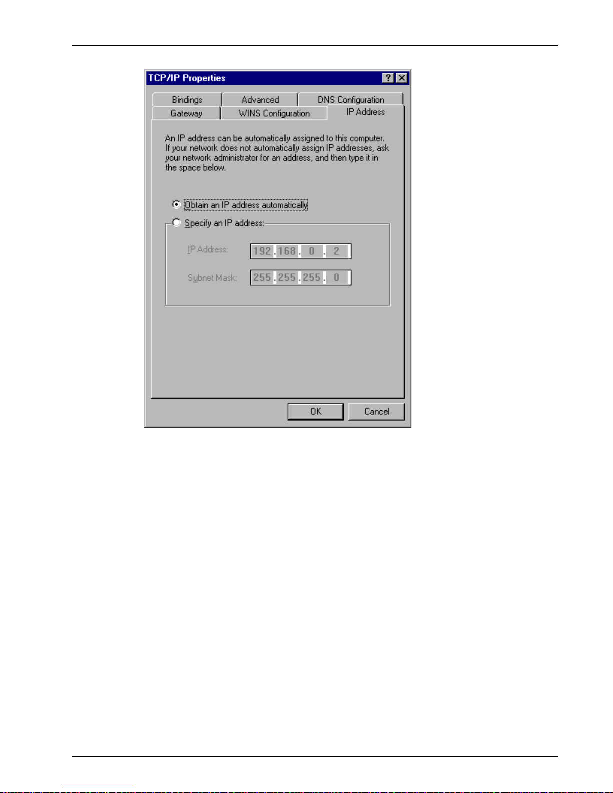
Chapter 5 - Client Setup
5. Select TCP/IP, then click Properties to open the TCP/IP Properties window.
6. Select the IP Address tab.
The IP addressing method depends on how your ProxyServer’s DHCP Server option was
configured. If DHCP Server is active, your IP address is issued automatically. If your network
administrator did NOT activate DHCP Services on the ProxyServer, you will have to assign your
IP address manually.
Verify the ProxyServer/DHCP status with your network administrator, then proceed to step 7 for
DHCP assigned addressing, or to step 8 for manual addressing.
7. If DHCP Services are active on the ProxyServer (default), verify that the Obtain an IP address
automatically option is selected. You are done; go to step 17 to reboot your PC and attempt to
open an Internet session.
MTPSR1-202ST
53
Page 54

ProxyServer User Guide
8. If DHCP Services are NOT active on the ProxyServer, you will have to manually enter your IP
address. Select manual addressing by clicking the Specify an IP address option. The IP
Address and Subnet Mask fields become active.
9. In the IP Address field, type the IP address assigned to your PC.
Remove the default IP address (if any) and begin typing the new address. This address is
entered in dotted decimal notation and is comprised of four groups (octets) separated by periods
or “dots.” If a group has fewer than 3 digits, type the necessary digits and press the space bar to
move to the next group. When you are finished, verify that the IP address is identical to the IP
address you were given for your PC.
54
MTPSR1-202ST
Page 55

10. Click the Gateway tab.
Chapter 5 - Client Setup
11. In the New gateway field, enter the IP address of the ProxyServer’s Ethernet port and click Add.
The new gateway address is displayed in the list of Installed gateways.
MTPSR1-202ST
55
Page 56

ProxyServer User Guide
12. Click the DNS Configuration tab. Verify that Enable DNS is selected (checked).
13. In the Host field, enter your user name (i.e., jerry).
14. In the Domain field, enter your company’s domain name (usually the company name followed by
one of the following extensions: .com, .edu, .gov , .org, .mil, or .net. For example, multitech.com).
15. In the DNS Server Search Order group, place the cursor in the first group of the address field
and type the IP address of your LAN’s DNS server (provided by your network administrator).
Click Add and the new address is displayed in the list below the address field.
Your network may have more than one DNS server, allowing you to use a secondary DNS server
if the primary DNS server is not available. If this is the case, add the IP address of the secondary
DNS server using the same procedure as with the first.
Note: The address that is displayed first (at the top) of the list is the primary server (the first one
searched). You can “drag and drop” the items in the list, if necessary , until the primary DNS
server is listed first.
When this is done, click OK. You are returned to the Network dialog.
56
MTPSR1-202ST
Page 57

16. In the Network dialog, Click OK. Y ou are returned to the Control Panel.
Use the following checklist to record all the configuration settings for future use:
Configuration Checklist
Chapter 5 - Client Setup
IP Address (PC)
IP Address (ProxyServer)
. . .
. . .
Host (User Name)
Domain
DNS Server Address
. . .
Network Adapter
(Manufacturer/Model Number)
17. Reboot the PC for changes to take effect.
At this point your client setup is complete. Test your setup by following steps 18 and 19. If you
encounter problems, contact your administrator.
18. Initiate an Internet session by double-clicking on your browser icon, or try to FTP a file.
Note: The ProxyServer operates transparently, so there should not be a need for any special
proxy settings on your IP applications (i.e., browser , Telnet, or FTP). Set up each application as
“No Proxy” or equivalent; or, connect to the Internet over the LAN.
19. To further validate your connection to the ProxyServer, “Ping” the IP address of the ProxyServer.
MTPSR1-202ST
57
Page 58
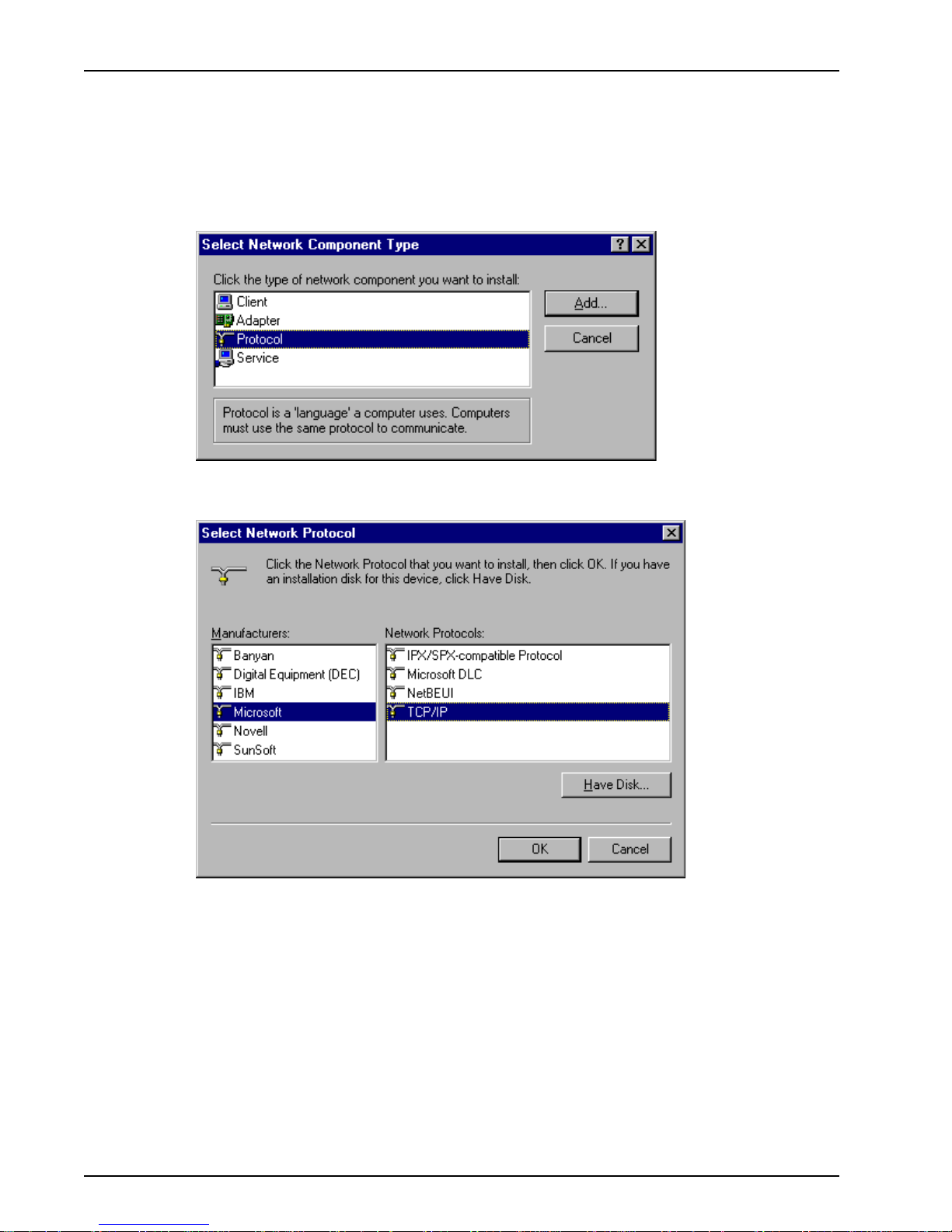
ProxyServer User Guide
Installing TCP/IP (Win98/95)
If TCP/IP is not already installed, perform the following steps:
Note: For this procedure you may need your Windows installation disks or CD ROM.
1. In the Network dialog box, click Add. The Select Network Component Type dialog is displayed
with a list of installation options.
2. Select Protocol and click Add. The Select Network Protocol dialog box is displayed with
protocol options.
3. In the Manufacturers list click the manufacturer option (Microsoft in the example) to highlight it. A
list of available protocols will appear in the Network Protocols list.
4. In the Network Protocols list, select TCP/IP and click OK.
5. Exit the add option. Click the OK button.
Note: If Windows does not find the necessary files on the hard drive, click Have Disk and follow
the on-screen instructions for loading TCP/IP from the installation disks/CD-ROM.
6. Reboot your PC for changes to take effect.
7. Click Start | Settings | Control Panel and double-click the Network icon to return to the
Network dialog. Return to step 3 of the Configuring in Windows 98/95 and continue with the
client setup procedure.
58
MTPSR1-202ST
Page 59
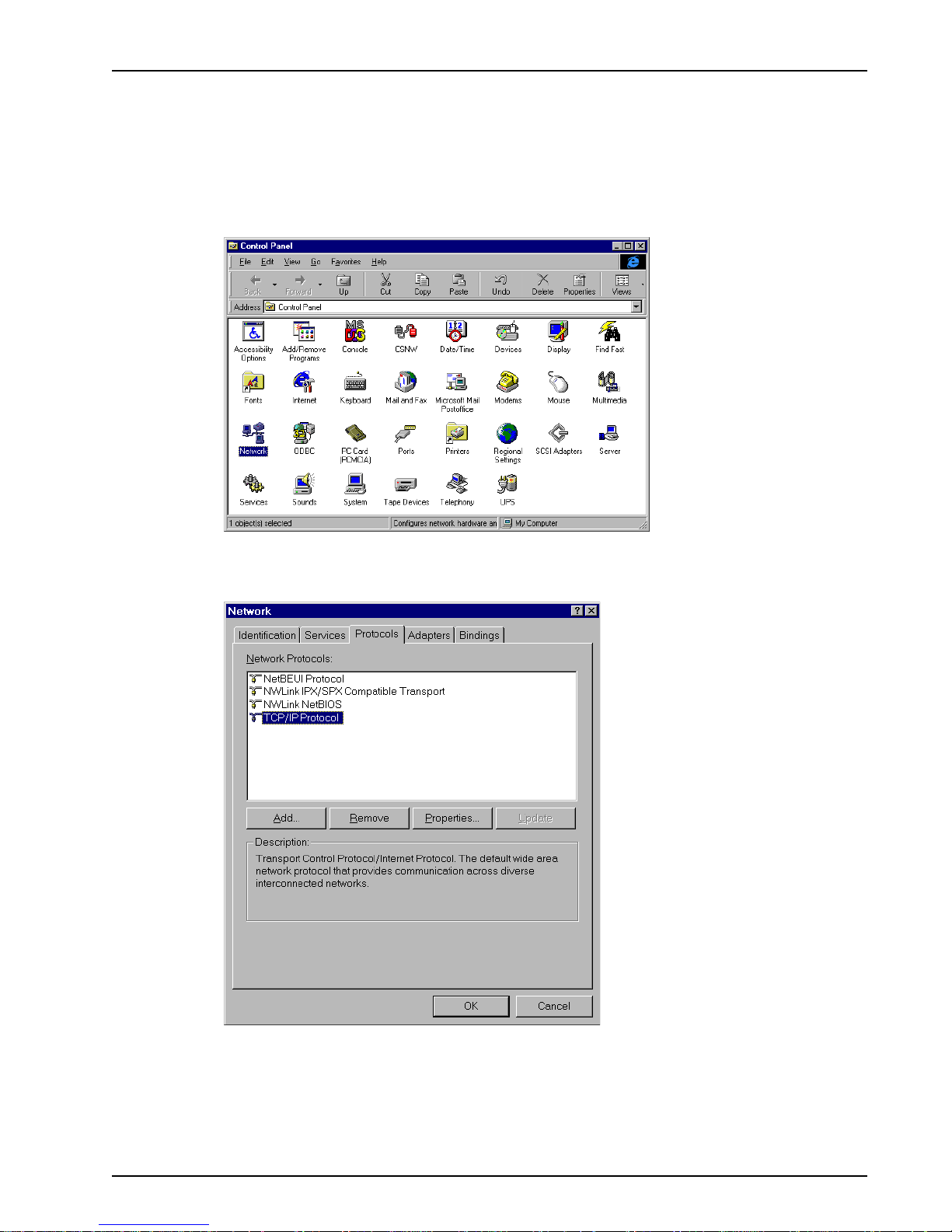
Configuring in Windows NT
Perform the following steps to set up your Windows NT workstation PC:
Note: All of the hardware and screen samples in this section are intended as examples only. Please
select options appropriate to your network.
1. Click Start | Settings | Control Panel.
Chapter 5 - Client Setup
Double click the Network icon.
2. The Network dialog box is displayed. Click the Protocols tab.
A list of protocols currently present on your PC is displayed. Check the installed protocols. If you
find TCP/IP Protocol listed, proceed to step 4. If TCP/IP is not listed, you must install it prior to
proceeding. Refer to Installing TCP/IP (WinNT) at the end of this section.
Click the Bindings tab.
MTPSR1-202ST
59
Page 60
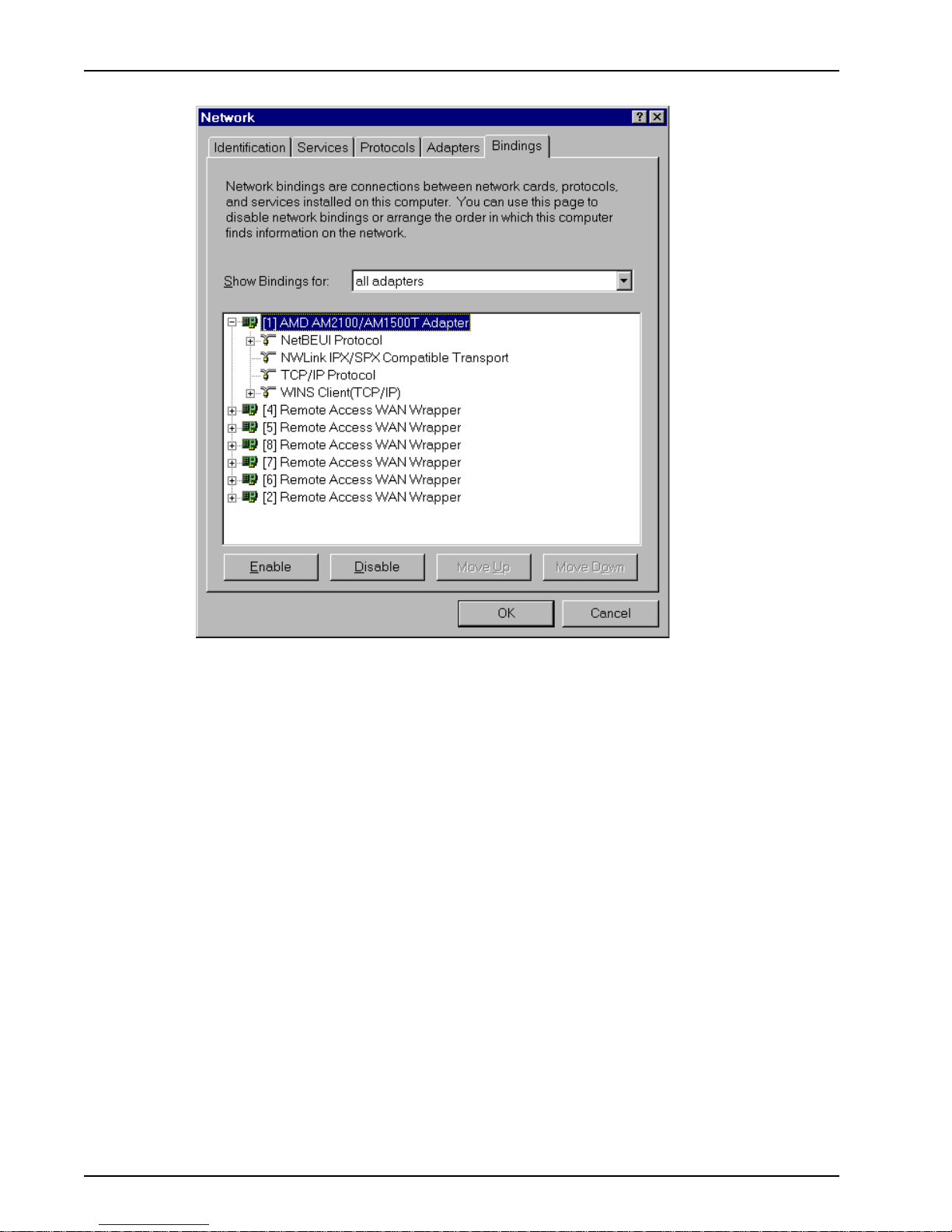
ProxyServer User Guide
3. The Bindings tab is displayed.
4. In the Show Bindings for drop down list, select all adapters. A list of all adapters is displayed.
5. Double click the entry for your Ethernet card adapter to expand the list of bindings. Verify that
TCP/IP Protocol is included in the bindings below your adapter .
Note: There may be other protocols in the list under your Ethernet adapter. This does not affect
the TCP/IP protocol. Rather, it simply means your computer will accept messages using those
protocols as well as TCP/IP.
6. Click the Protocols tab.
60
MTPSR1-202ST
Page 61
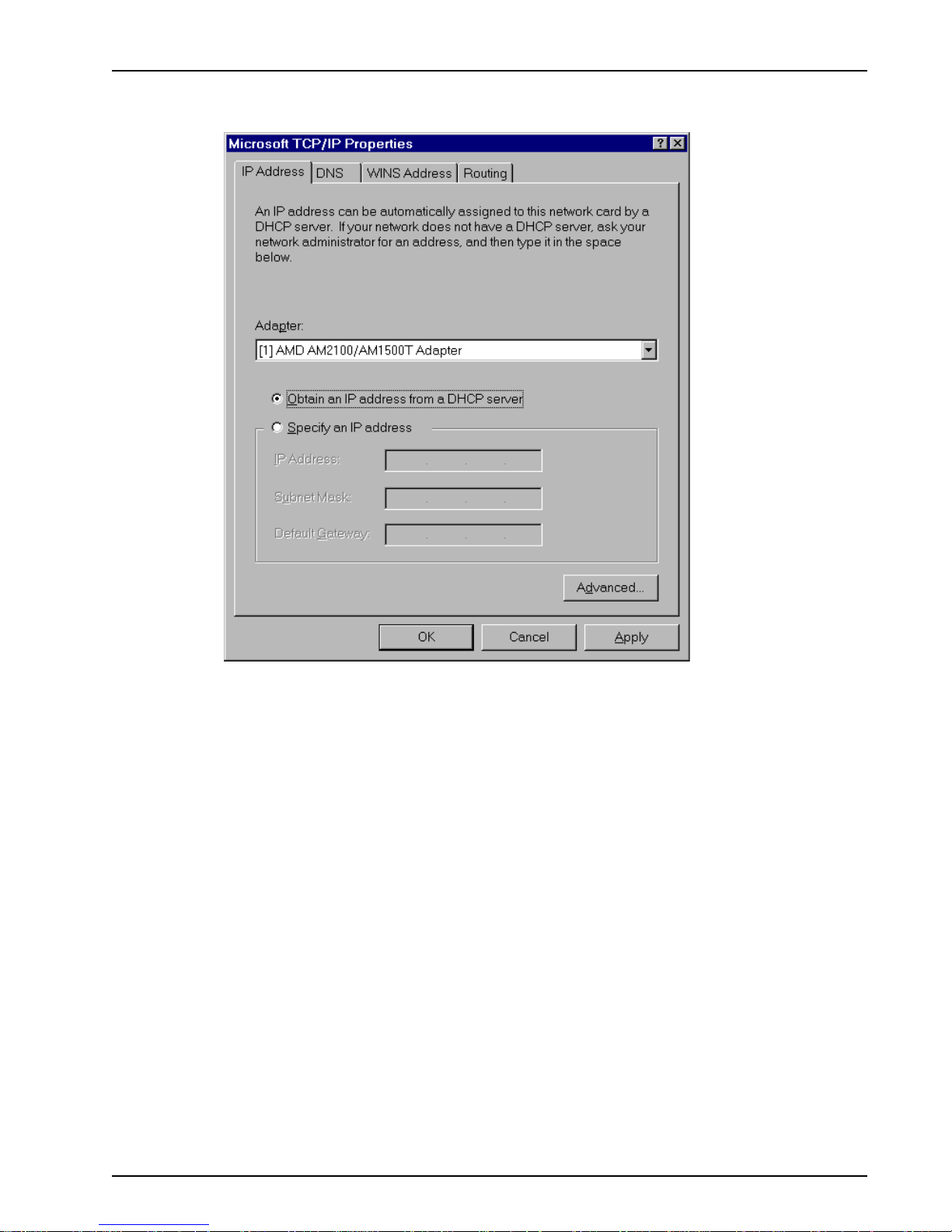
Chapter 5 - Client Setup
7. In the Network Protocols list select TCP/IP, then click Properties. The Microsoft TCP/IP
Properties dialog is displayed.
8. Click the IP Address tab.
The IP addressing method depends on how your ProxyServer’s DHCP Server option was
configured. If DHCP Server is active, your IP address is issued automatically. If your network
administrator did NOT activate DHCP Services on the ProxyServer, you will have to assign your
IP address manually.
Verify the ProxyServer/DHCP status with your network administrator, then proceed to step 9 for
DHCP assigned addressing, or to step 10 for manual addressing.
9. If DHCP Services are active on the ProxyServer (the default), verify that the Obtain an IP
address from a DHCP server option is enabled (checked). At this point, you are done. Go to
step 20 and attempt to open an Internet session.
MTPSR1-202ST
61
Page 62
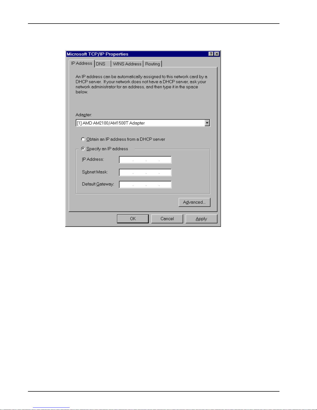
ProxyServer User Guide
10. If DHCP Services are NOT active on the ProxyServer , you will have to manually enter your IP
address. Select manual addressing by clicking the Specify An IP Address option. The IP
Address and Subnet Mask fields become active.
11. In the IP Address field, type the IP address assigned to your PC.
Remove the default IP address (if any), and begin typing the new address. This address is
entered in dotted decimal notation and is comprised of four groups (octets) separated by periods
or “dots.” If a group has fewer than 3 digits, type the necessary digits and press the space bar to
move to the next group. When you are finished, verify that the IP address is identical to the IP
address you were given for your PC.
12. In the Subnet Mask field, type the subnetwork mask assigned by your administrator. When you
are finished, verify the new mask.
13. In the Default Gateway field, type the IP address of the gateway assigned to your LAN. When
you are finished, verify the new gateway .
62
MTPSR1-202ST
Page 63
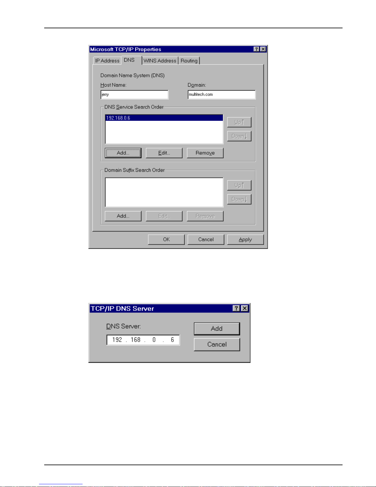
Chapter 5 - Client Setup
14. Click the DNS tab. The Domain Name System (DNS) properties are displayed.
15. In the Host Name field, type your user name (i.e., jerry).
16. In the Domain field, enter your company’s domain name (usually the company name followed by
one of the following extensions: .com, .edu, .gov , .org, .mil, or .net. For example, multitech.com).
17. In the DNS Server Search Order group, click Add. The TCP/IP DNS Server dialog box is
displayed.
18. In the DNS Server field, place the cursor in the first group and type the IP address of your LAN’s
DNS server (provided by your network administrator).
MTPSR1-202ST
63
Page 64

ProxyServer User Guide
19. Click Add. You are returned to the Microsoft TCP/IP Properties dialog box, DNS tab, and the
new address is displayed in the DNS Search Order list.
Your network may have more than one DNS server, allowing you to use a secondary DNS server
if the primary DNS server is not available. If this is the case, add the IP address of the secondary
DNS server using the same procedure as with the first.
Note: The address that appears first (at the top of the list) is the primary server (the first one
searched). You can use the Up and Down buttons to rearrange the items in the list, if necessary,
until the primary DNS server is listed first.
When this is done, click OK. You are returned to the Network dialog box.
Use the following checklist to record all the configuration settings for future use:
Configuration Checklist
IP Address (PC)
IP Address (ProxyServer)
. . .
. . .
Host (User Name)
Domain
DNS Server Address
. . .
Network Adapter
(Manufacturer/Model Number)
20. Reboot the PC for changes to take effect.
At this point your client setup is complete. Test your setup by following steps 21 and 22. If you
encounter problems, contact you administrator.
21. Initiate an Internet session by double-clicking your browser icon, or try to FTP a file.
Note: The ProxyServer operates transparently, so there should not be a need for any special
proxy settings on your IP applications (i.e., browser , Telnet, or FTP). Set up each application as
“No Proxy” or equivalent; or, connect to the Internet over the LAN.
22. To further validate your connection to the ProxyServer, “Ping” the IP address of the ProxyServer.
64
MTPSR1-202ST
Page 65

Installing TCP/IP (WinNT)
If TCP/IP is not already installed, perform the following steps:
Note: For this procedure you may need your Windows NT installation CD ROM.
1. While the Network dialog box is open, click Add.
Chapter 5 - Client Setup
2. The Select Network Protocol dialog box is displayed with a list of available protocol options.
Highlight TCP/IP Protocol and click OK.
If necessary (i.e., the operating system does not find the necessary files on the hard drive), click
the Have Disk button, then follow the instructions provided on-screen.
3. You are returned to the Network dialog.
4. Reboot your PC for changes to take effect.
5. Open the Control Panel and double-click the Network icon to return to the Network Configuration
window, then go to step 4 of the Configuring Windows NT procedure.
MTPSR1-202ST
65
Page 66

ProxyServer User Guide
66
MTPSR1-202ST
Page 67

Chapter 6 - RAS Dial-Out Redirector
Page 68

ProxyServer User Guide
Introduction
Multi-Tech’s Remote Access Server for Microsoft network users enables users to dial-out and fax-out
through your MTPSR1-202ST. Remote Access Solution software uses Multi-Tech’s Communications
Services Interface (MCSI - pronounced “Mik-see”). MCSI is a software redirector which complies
with MCSI/NCSI/NASI defacto standards for software redirection.
The Windows© version of MCSI, called WINMCSI, is supported on Win 3.1x, Windows 98/95, and
Windows NT platforms. Since WINMCSI provides data communications connectivity, it needs to be
installed and operating before your data communications application software is started.
Installing and Configuring the WINMCSI Modem-Sharing
Software
The WINMCSI modem-sharing software (included on the CD) manages access to a Asynchronous
Gateway (AG) for outbound calls. It allows Windows communications software packages that do not
support INT6B or INT14 to connect to a gateway . It also detects other compatible communications
servers (e.g., RASs) on your network and displays the resources they provide to eligible LAN users.
To install WINMCSI in Windows 3.1, Windows for Workgroups 3.1 1, Windows 98/95, or Windows NT,
follow the steps below:
1. Power on your client PC and log in to your LAN.
2. Start Windows.
3. Insert the Multi-Tech ProxyServer CD into your CD-ROM drive. The AutoRun Install Shield is
displayed.
- Close the AutoRun dialog box.
- Double-click your My Computer icon.
- Right-click the CD-ROM drive icon.
- Click Open. The CD-ROM file displays the following.
WINMCSI - Double-click to open the folder for Windows 3.1 and 3.1 1 operating systems.
W95MCSI - Double-click to open the folder for Windows 98/95 operating systems.
NTMCSI - Double-click to open the folder for Windows NT operating systems.
4. Begin the software installation:
- Windows 3.1 and Windows for Workgroups 3.11 users double-click the Install icon. Proceed
to step 5.
- Windows 98/95 users double-click the Inst95 icon. WINMCSI will install as either a 16-bit or
32-bit program, depending on your system. Windows 98/95 will locate the proper install.exe
file.
If your system is a 16-bit system, proceed to Step 5.
If your system is a 32-bit system, proceed to Step 15.
- Windows NT users double-click the Setup icon and proceed to step 15.
68
MTPSR1-202ST
Page 69

Chapter 6 - RAS Dial-Out Redirector
5. If you installed in Windows 3.1, Windows for Workgroups 3.1 1, or W indows 98/95 (as a 16-bit
version):
The WINMCSI Installation Program window is displayed.
Click Continue to proceed with the installation.
6. The WinMCSI Install Configuration window is displayed.
In the Destination Directory field, type in the name of the directory to which you want to install
WINMCSI, or you can accept the default: C:\COMMCSI.
7. In the Network Type dialog box, click the appropriate network type (IP). Because the default is
IPX, you will need to select IP.
Click Continue to proceed with the WINMCSI installation.
MTPSR1-202ST
69
Page 70

ProxyServer User Guide
8. When the Installing Multi-T ech WINMCSI window is displayed, click the Install button to begin
the installation. Click Abort at any time to cancel the installation
9. When the installation is complete, the WinMCSI Installation window is displayed.
Click Modify INI files now to have WINMCSI automatically make changes to your SYSTEM.INI
and WIN.INI files.
Click the Save changes to file button to have WINMCSI make a copy of the changes to be
made and store them in a file.
Note: Because you must make the changes before you can run WINMCSI, it is recommended
that you choose Modify INI files now.
A screen is displayed telling you that your installation is complete and where your WIN.INI and
SYSTEM.INI files are backed up.
10. The following message is displayed:
Click Yes or No, as appropriate.
70
MTPSR1-202ST
Page 71

Chapter 6 - RAS Dial-Out Redirector
1 1. The following message is displayed:
If you want to map your COM ports now, click Yes and proceed to step 12.
If you want to wait to map your COM Ports until you start WINMCSI, click No and proceed to step
13.
12. The COM Port to MCSI Mapping window is displayed.
If you want to get the first available line, click Map | Close and go to the next section.
If you want a specific line, click a COM port in the Local Port list box, then click the line to which
you want to map that particular COM Port. The status message "Mapped to MCSI" should
appear above the Local Port list box.
Click the Unmap button if you want to unmap a line.
Click the Search button to search for lines on a server.
Click the Close button when finished.
13. The following message is displayed: “WINMCSI Successfully Installed”. Click OK.
14. A message is displayed telling you where your old SYSTEM.INI and WIN.INI files have been
backed-up. The message also tells you to restart Windows. Click Restart Windows to complete
the installation.
At this time Your WINMCSI software installation is complete. Proceed to the next section,
“Running the WINMCSI Workstation Software.”
MTPSR1-202ST
71
Page 72

ProxyServer User Guide
If you installed in Windows 98/95 (as a 32-bit version) or Windows NT:
15. The Welcome screen is displayed.
Click Next to proceed with the installation.
16. The Choose Destination Location screen is displayed.
Click Next to accept the Destination Folder, or click Browse to select a different destination.
17. The Select Program Folder screen is displayed.
Click Next to accept the new folder designation, or choose an existing folder from the list
provided.
72
MTPSR1-202ST
Page 73

Chapter 6 - RAS Dial-Out Redirector
18. The Choose Network T ype screen is displayed.
Selections include IPX, NetBIOS, and IP (default is IPX). Click IP and then click Next to
proceed.
19. The COM Port to MCSI Mapping window is displayed.
Click Add Port to add a port to the Local Port list box.
If you want a specific line, click a COM port in the Local Port list box, then click the line to which
you want to map that particular COM Port. The status message "Mapped to MCSI" should
appear above the Local Port list box.
Click Remove Port to permanently remove a port from the Local Port list box.
Click the Unmap button if you want to unmap a line.
Click the Search button to search for lines on a server.
Click the Close button when finished.
At this time Your WINMCSI software installation is complete. Proceed to the next section,
“Running the WINMCSI Workstation Software.”
Note: Once MCSI has been installed and configured, make certain that the appropriate ISDN T A
drivers are installed on your PC. The ISDN TA drivers can be found in the “Drivers” directory on the
ProxyServer CD.
MTPSR1-202ST
73
Page 74
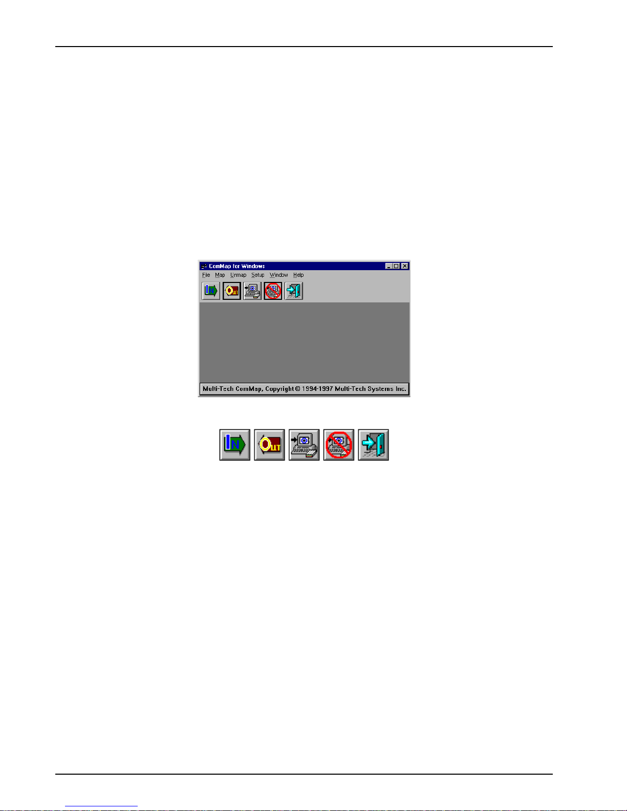
ProxyServer User Guide
Running the WINMCSI Workstation Software
WINMCSI has a workstation portion of the software that LAN users run and use to log onto the
communications server prior to running datacomm software on their client PCs. The following steps
guide you through this process.
1. Start WINMCSI.
Windows 3.1, Windows for Workgroups 3.11, or Windows 95 (16-bit) users:
To start WINMCSI, double-click the ComMap icon in your Program Manager in Windows. The
ComMap for Windows window is displayed. Go to step 2.
Windows 98/95 (32-bit) and Windows NT users:
To start WINMCSI, click Start | Programs | MultiTech MCSI | ComMap.
2. The ComMap for Windows window is displayed.
The buttons from left to right are: Login, Logout, Map, Unmap, and Exit.:
3. To setup ComMap, click Setup.
Click the Network T ype command. The Network Type dialog box is displayed. Your current
network type is highlighted. You can change the network type by clicking the option button
appropriate for your network. Click OK when finished. You must restart Windows if you change
this setting.
Note: Do not change the network type unless you have changed the network. Also, make sure
that your SYSTEM.INI file contains the device drivers specific to the selected network type.
Click the Connect Timer command. The MCSI Connect Timer dialog box is displayed. The
default value of the connect timer is shown in the Enter Connect Timer Value field. T o change the
value of the connect timer, type in a dif ferent value. Click OK when finished.
Click the Baud Change command. The ComMap Baud Change message is displayed. If baud
change by an application is permitted, then this command is checked in the Setup Menu. If baud
change is unchecked in the Setup Menu, then an application cannot change the baud rate (or
other port parameters). Answer the message appropriately.
Click the Default Login command. The Default Login Parameters dialog box is displayed.
Use this dialog box to select a specific RAS to which you want to log into next time Windows is
loaded. Click a RAS from the Available Servers box. If there are no servers in the Available
Servers box, then click the Search button. Type in a User Name and Password (optional) in
their respective fields. Click OK when finished.
74
MTPSR1-202ST
Page 75
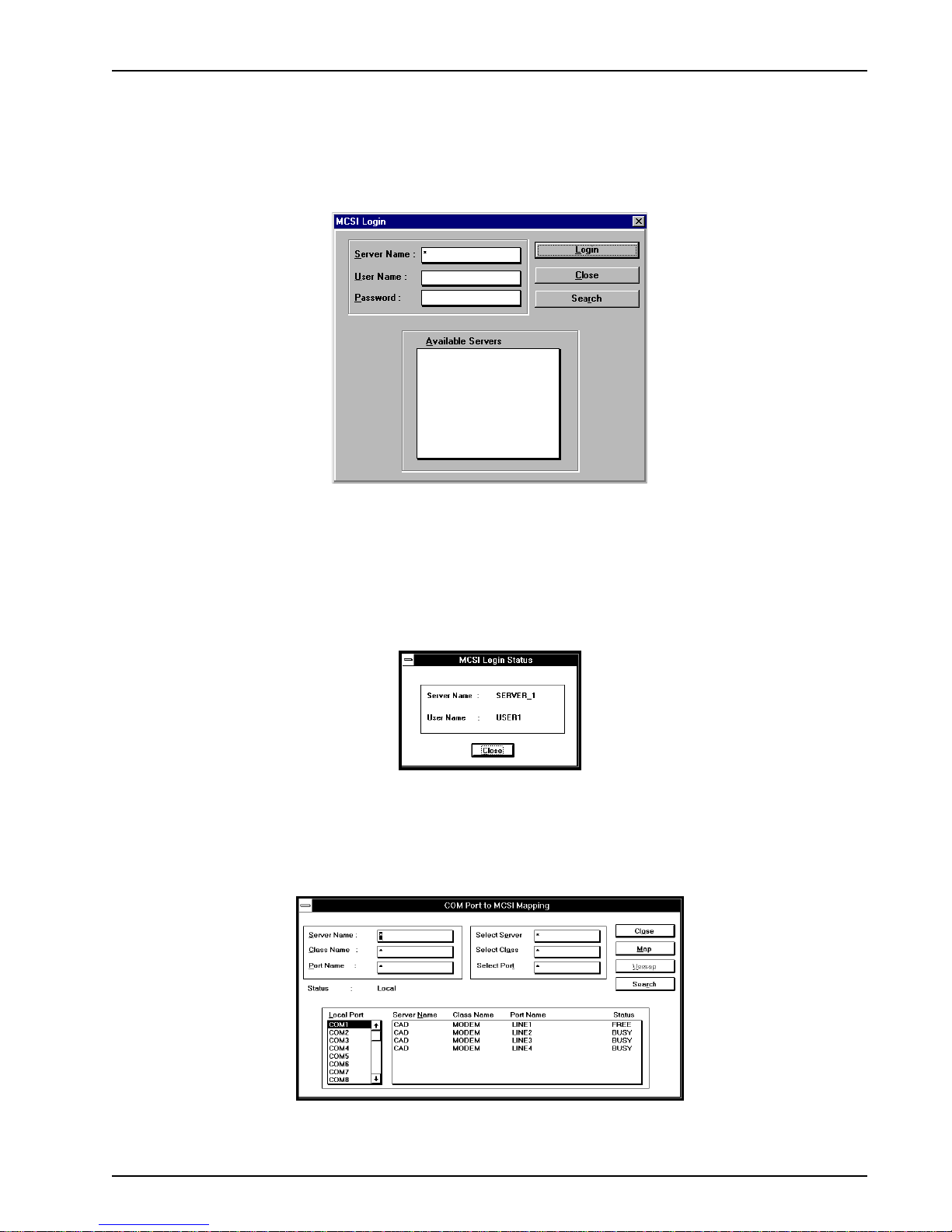
Chapter 6 - RAS Dial-Out Redirector
ComMap saves these login parameters in your COMMCSI.INI file.
Note: You cannot directly edit the COMMCSI.INI file using a text editor because the password
field is encrypted.
4. If you have not logged into the network, do so now by clicking File | Login, or click the Login
button. The MCSI Login window is displayed.
The Available Servers box lists the names of the available servers. Click the name of the server
to which you want to attach, type a User Name and Password in their respective fields, and then
click Login. A window is displayed stating that your login was successful. Click OK. If there are
no servers listed in the Available Servers box, then click the Search button to search for a
server.
5. At the ComMap for Windows main window, view your log status by clicking File | Log Status.
The MCSI Login Status window is displayed.
This window shows the name of the server to which you are logged in and the name with which
you logged in. Click Close when you are finished.
6. At the ComMap for Windows main window (to map a COM port through MCSI) click Map | Map.
The COM Port to MCSI Mapping window is displayed.
MTPSR1-202ST
75
Page 76

ProxyServer User Guide
Note: Windows 98/95 users will have two additional buttons in this box, the Add Port and the
Remove Port buttons. You must click the Add Port button to view Local Ports. Click the
Remove Port button to remove Local Ports.
If you want to get the first available line, click the Map button and then click the Close button and
go to step 7.
If you want a specific line, click a COM Port in the Local Port list box, then click the line to which
you want to map that particular COM Port. The status message "Mapped to MCSI" should
appear above the Local Port list box.
Click Unmap if you want to unmap a line.
Click Search to search for lines on a server .
Click Close when finished.
7. To view a list of mapped COM ports, click Map | Map List, or click the Map button. Click Close
when finished.
Below is an example of the Window's Terminal application's (shipped with all versions of
Windows) Communications dialog box. After mapping your COM Ports with ComMap for
Windows, you can check your connectivity and configure your ports with Windows Terminal. It is
recommended that you use the settings shown in the example below (in the example COM1 is
shown).
8. To unmap a COM port, click Unmap | Unmap, or click the Unmap button. Click the listing you
want to unmap and then click Unmap.
9. To logout from the network, click File | Logout, or click the Logout button.
10. To exit from WINMCSI, click File | Exit, or click the Exit button. Otherwise you may minimize the
screen to minimize WINMCSI to an icon.
76
MTPSR1-202ST
Page 77

Chapter 7 - Remote Configuration
Page 78
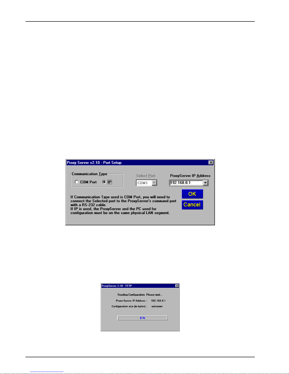
ProxyServer User Guide
Introduction
This chapter provides procedures for viewing or changing the configuration of a remote unit.
Remote configuration requires the ProxyServer software to be loaded on the local PC. The local PC
then controls the remote ProxyServer via the LAN.
Remote Configuration
Remote configuration is LAN-based andrequires a Windows Sockets compliant TCP/IP stack. TCP/IP
protocol software that must be installed and functional before the configuration program can be used.
1. You must assign an Internet (IP) address for the PC and for each node that will be managed by
the configuration program. Refer to the protocol software documentation for instructions on how
to set the IP addresses.
Once you have completed this step, you should be able to use the protocol Ping command for
the PC host name. You should also test the network interface configuration by Pinging another
TCP/IP device that is connected to the network.
2. Install the ProxyServer software on the local PC. Once installed click Start | Programs |
ProxyServer 2.10 | Configuration Port Setup.
3. The Port Setup dialog box is displayed.
Verify that the Communication Type field is set IP.
In the ProxyServer IP Address field, enter the IP Address of the remote ProxyServer.
4. Click OK when you are satisfied with your selections.
The windows Program Manager menu is displayed.
5. Double-click the ProxyServer Configuration icon.
The Reading Configuration dialog box is displayed.
78
MTPSR1-202ST
Page 79
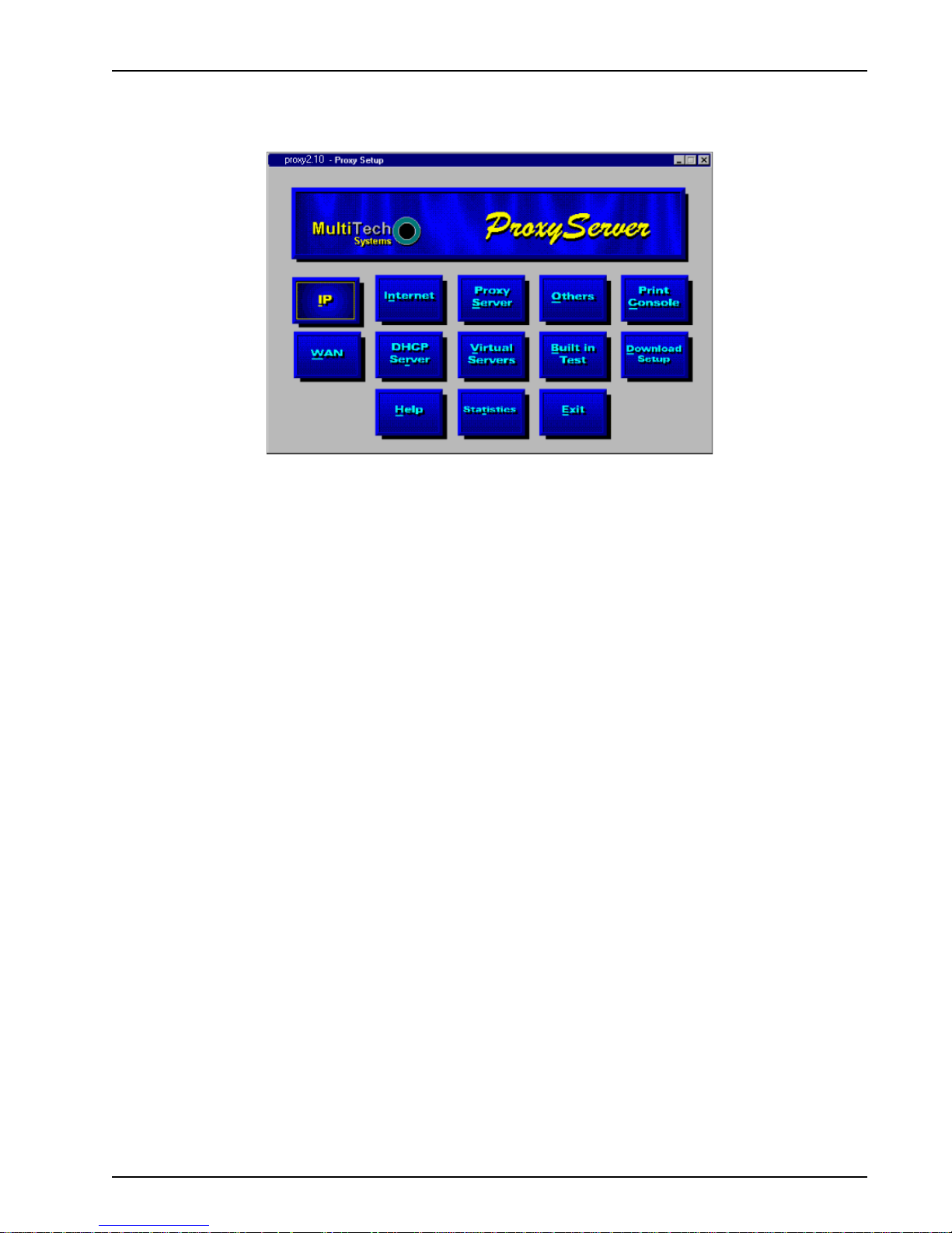
Chapter 7 - Remote Configuration
6. Once the the configuration has been read, the Proxy Setup dialog box is displayed. This is the
dialog box of the remote ProxyServer. For definitions of each dialog box or field within a dialog
box, refer to the on-line Help provided in the ProxyServer software.
7. After you have changed the configuration of the remote ProxyServer, click the Download Setup
button to update the configuration. The remote ProxyServer will be brought down, the new
configuration written to the unit, and the unit will reboot.
8. Click the Exit button when the downloading is complete.
9. Click the ProxyServer Configuration icon in the Program Manager screen to verify that the
ProxyServer is running.
MTPSR1-202ST
79
Page 80

ProxyServer User Guide
80
MTPSR1-202ST
Page 81

Chapter 8 - ProxyServer Management
Page 82

ProxyServer User Guide
Telnet ProxyServer Configuration
A typical Telnet client application and typical Web-browser management of the ProxyServer are
described in this chapter. The ISDN ProxyServer has a built-in Telnet Server that enables Telnet
client PCs to access the ProxyServer. A typical Telnet client is allowed to configure the ProxyServer
and WAN devices. In addition, the ProxyServer can be remotely accessed and configured from
anywhere on the Internet through its Web interface.
For a detailed description of the ProxyServer software and individual parameters, refer to Chapter 4
in this User Guide. For a detailed description of each parameter, refer to the on-line Help provided
within your ProxyServer software.
The TCP/IP stack has to be loaded before the Telnet client (a Windows application) will run. The
Telnet Server option also has to be selected from the Applications Setup dialog box by clicking the
Other button in the Proxy Setup main menu. Then, double-click the Telnet icon (or shortcut) and a
blank Telnet screen is displayed. Click Connect to display the menu options. Select the Remote
System option and the Connect dialog box is displayed. Select (or enter) a Host Name (the IP
address of the ProxyServer whose configuration you want to either view or change). In this example,
the Host Name is 192.168.0.1.
When you enter a valid Host Name (IP address) and click the Connect button, you are immediately
connected to the target ProxyServer and the ProxyServer Management Menu is displayed.
The ProxyServer management menu provides several basic options, including Dial-out, ProxyServer
Management, ProxyServer Configuration, and WAN Device Configuration. (The Remote User
DataBase is not used in the ProxyServer application.)
82
MTPSR1-202ST
Page 83

Chapter 8 - ProxyServer Management
Dial-out
Selecting Option 1 displays the Dial-out Ports menu which shows whether the ProxyServer’s WAN
port (Port 1) is currently available for dialing out.
ProxyServer Management
Selecting Option 2 displays the ProxyServer Management menu with options that enable you to
obtain ProxyServer statistics, obtain system information, or reset the ProxyServer.
ProxyServer Configuration
Selecting Option 3 on the ProxyServer Management Menu opens the ProxyServer Configuration
menu, with options that correspond to seven buttons on the Proxy Setup screen or Main Menu. They
include IP, Internet, WAN, Others, ProxyServer, DHCP Server, and Virtual Servers.
WAN Device Configuration
Selecting option 4 on the ProxyServer Management Menu enables you to gain direct access to the
ISDN Line on the WAN port in WANTalk mode.
Remote User DataBase
Selecting Option 5 on the ProxyServer Management Menu displays the Remote User DataBase
menu which is not used in this application.
Applications (Others)
Selecting Option 4 on the ProxyServer Configuration menu displays the Others menu which allows
you to enable or disable various remote servers or set up password protection for the ProxyServer.
MTPSR1-202ST
83
Page 84

ProxyServer User Guide
To enable or disable a given type of remote server, choose the server option number and hit the
Enter key . Then choose either option 1 to enable the server or option 2 to disable the server. The
following is a description of each type of remote server and its use.
TFTP Server - The TFTP server is used for configuration and firmware updates across the IP
internetwork. TFTP is a file transfer protocol that uses UDP and provides a simple method for
transferring files between two nodes (the server and client).
T elnet Server - The Telnet server enables an authorized Telnet client to remotely access the T elnet
server to dial out, view ProxyServer configuration and statistics, or modify the ProxyServer
configuration.
Web Server - The Web Server option permits a remote user to enable the ProxyServer’s Web Server
and then configure the ProxyServer using a web browser.
Dumb TTY - The Dumb TTY option enables a remote user to connect to the ProxyServer’s command
port for configuration and management of the ProxyServer.
when you have finished viewing or changing the configuration of the remote ProxyServer, press the
Esc key to to back out through the previous menus until you reach the ProxyServer Management
Menu, where you can close the Telnet Session and save any changes to the remote ProxyServer.
84
MTPSR1-202ST
Page 85

WEB Management
The ProxyServer can be accessed, via a standard web browser, from anywhere on the connected
Internet. To provide this support, the WEB Server option has to be enabled in the Applications Setup
dialog box (see Chapter 4 - ProxyServer Configuration, Applications).
Once the Web Server is enabled, users can access the ProxyServer by entering its IP address in the
Destination (or Location) field of their web browser, at which time the following screen will be
displayed.
Click the word “Login” to log in to the ProxyServer configuration utility . The Enter Network Password
screen is displayed.
Chapter 8 - ProxyServer Management
Type supervisor in the User Name field and click OK to continue; no password is required.The next
screen displayed is the “Frame View” of the ProxyServer Configuration screen, with two basic
selections: Stacks & Drivers, and Other setup.
MTPSR1-202ST
85
Page 86

ProxyServer User Guide
If you prefer a different presentation, you can click ‘
Standard View’ to open the following screen:
In the Stacks & Drivers category, IP, Internet, and WAN correspond to three buttons on the Proxy
Setup screen or main menu. In the Other Setup category, ProxyServer, Virtual Server, Others, and
DHCP Server correspond to four other buttons on the main menu. Statistics enables you to view the
operating statistics for the ProxyServer, and the User Database button is not used in this application.
Clicking on ‘Others’ opens the ProxyServer Application Setup screen which allows you to enable
or disable the four types of servers that are built into the ProxyServer.
When you are finished viewing or changing the configuration of the remote ProxyServer, return to the
Standard View or Framed View of the ProxyServer Configuration screen and double-click ‘Write the
setup and Reboot.’
86
MTPSR1-202ST
Page 87

Chapter 9 - Service, Warranty
and Tech Support
Page 88

ProxyServer User Guide
Introduction
This chapter starts out with statements about your ProxyServer 2-year warranty . The next section,
Tech Support, should be read carefully if you have questions or problems with your ProxyServer. It
includes the technical support telephone numbers, space for recording your product information, and
an explanation of how to send in your ProxyServer should you require service. The final three
sections explain how to use our bulletin board service (BBS), and get support through CompuServe
and the Internet.
Limited Warranty
Multi-Tech Systems, Inc. (“MTS”) warrants that its products will be free from defects in material or
workmanship for a period of two years from the date of purchase, or if proof of purchase is not
provided, two years from date of shipment. MTS MAKES NO OTHER WARRANTY, EXPRESSED
OR IMPLIED, AND ALL IMPLIED WARRANTIES OF MERCHANTABILITY AND FITNESS FOR A
PARTICULAR PURPOSE ARE HEREBY DISCLAIMED. This warranty does not apply to any
products which have been damaged by lightning storms, water, or power surges or which have been
neglected, altered, abused, used for a purpose other than the one for which they were manufactured,
repaired by the customer or any party without MTS’s written authorization, or used in any manner
inconsistent with MTS’s instructions.
MTS’s entire obligation under this warranty shall be limited (at MTS’s option) to repair or replacement
of any products which prove to be defective within the warranty period, or, at MTS’ s option, issuance
of a refund of the purchase price. Defective products must be returned by Customer to MTS’s factory
transportation prepaid.
MTS WILL NOT BE LIABLE FOR CONSEQUENTIAL DAMAGES AND UNDER NO
CIRCUMSTANCES WILL ITS LIABILITY EXCEED THE PURCHASE PRICE FOR DEFECTIVE
PRODUCTS.
On-line Warranty Registration
If you would like to register your ProxyServer electronically , you can do so at the following address:
http://www.multitech.com/register/
88
MTPSR1-202ST
Page 89

Tech Support
Multi-Tech has an excellent staff of technical support personnel available to help you get the most out
of your Multi-Tech product. If you have any questions about the operation of this unit, call 1-800-972-
2439. Please fill out the ProxyServer information (below), and have it available when you call. If your
ProxyServer requires service, the tech support specialist will guide you on how to send in your
ProxyServer (refer to the next section).
Recording ProxyServer Information
Please fill in the following information on your Multi-Tech ProxyServer. This will help tech support in
answering your questions. (The same information is requested on the Warranty Registration Card.)
Model No.: _________________________
Serial No.: _________________________
Software Version: ____________________
The model and serial numbers are on the bottom of your ProxyServer.
Please note the type of external link device that is connected to your ProxyServer before calling tech
support. Also, note the status of your ProxyServer including LED indicators, screen messages,
diagnostic test results, problems with a specific application, etc. Use the space below to note the
ProxyServer status:
Chapter 9 - Service, Warranty, and Tech Support
________________________________________________________________________________________________________
________________________________________________________________________________________________________
________________________________________________________________________________________________________
________________________________________________________________________________________________________
______________________________________________________________________________________________________________
______________________________________________________________________________________________________
______________________________________________________________________________________________________________
______________________________________________________________________________________________________
MTPSR1-202ST
89
Page 90

ProxyServer User Guide
Service
If your tech support specialist decides that service is required, your ProxyServer may be sent (freight
prepaid) to our factory . Return shipping charges will be paid by Multi-Tech Systems.
Include the following with your ProxyServer:
• a description of the problem.
• return billing and return shipping addresses.
• contact name and phone number .
• check or purchase order number for payment if the ProxyServer is out of warranty. (Check
with your technical support specialist for the standard repair charge for your ProxyServer).
• if possible, note the name of the technical support specialist with whom you spoke.
If you need to inquire about the status of the returned product, be prepared to provide the serial
number of the product sent.
Send your ProxyServer to this address:
You should also check with the supplier of your ProxyServer on the availability of local service and/or
loaner units in your area.
MULTI-TECH SYSTEMS, INC.
2205 WOODALE DRIVE
MOUNDS VIEW, MINNESOTA 55112
ATTN: SERVICE OR REPAIRS
90
MTPSR1-202ST
Page 91

About the Multi-Tech BBS
Multi-Tech Systems maintains a Bulletin Board Service (BBS) for its customers. The information
available via the BBS includes: new product information, product upgrade data, problem solving tips,
and a message service for you to leave questions for which you would like additional information. The
phone number for the Multi-Tech BBS is (612) 785-3702 or (800) 392-2432 (U.S.A. and Canada).
The BBS can be accessed by any asynchronous modem operating at speeds of 33,600 -1200 bps
with a setting of word length of 8 bits, 1 stop bit, and no parity .
Logging on to the Multi-Tech BBS
To log on to the Multi-Tech BBS, perform the following steps.
1. Set your communications program to 8-N-1.
2. Dial our BBS at (800) 392-2432 (USA and Canada) or (612) 785-3702 (international and local).
3. At the prompts, type your first name, last name, and password; then press RETURN. If you are a
first time caller, the BBS will ask if your name is spelled correctly. If you answer yes, a
questionnaire will appear. You must complete the questionnaire to use the BBS on your first call.
4. Press RETURN until the Main Menu appears. From the Main Menu you have access to three
main areas: the Files Menu, the Message Menu, and Bulletins. For help on menu commands,
type ?.
Chapter 9 - Service, Warranty, and Tech Support
Downloading a File
If you know the file name
1. From the Main Menu, type F to access the Files Menu, then type D.
2. Enter the name of the file you wish to download from the BBS.
3. If a password is required, enter the password.
4. Answer Y or N to the automatic logoff question.
5. Select a file transfer protocol by typing the indicated letter, such as Z for Zmodem (the
recommended protocol).
6. If you select Zmodem, the transfer will begin automatically . If you select another protocol, you
may have to initiate the transfer yourself. (In most datacomm programs, the P AGE DOWN key
initiates the download.)
If you don’t know the file name
1. From the Main Menu, type F to access the Files Menu. For a list of file areas, type L twice. (If you
do not type the second L, you will list all of the files on the BBS.)
2. Mark the file areas you would like to examine by typing each file area’s list number and a
RETURN.
3. Enter L to list all the files in the selected file areas. Enter C to go forward in the file list and P to
go back.
4. Mark one or more files for download by entering M, the list numbers of the files, and a RETURN.
5. Enter D. You will see a list of the files you have marked. Enter E if you would like to edit the list;
otherwise enter D again to start the download process.
MTPSR1-202ST
91
Page 92

ProxyServer User Guide
6. Select a file transfer protocol by typing the indicated letter, such as Z for Zmodem (the
recommended protocol).
7. If you select Zmodem, the file will transfer automatically . If you select another protocol, you may
have to initiate the transfer yourself. (In MEWTERM and many other communications programs,
the P AGE DOWN key initiates the download.)
8. When the download is complete, enter S to return to the File Menu.
Reading a Message
When you log on, the BBS will tell you if you have a personal message (mail). At the prompt Would
you like to read it now?, type R to read the message. This is the only point at which you can read
your mail, since you cannot read any messages from the Message Menu.
Leaving a Message
The Multi-Tech BBS has no public discussion areas. To leave a personal message, select the
Message Menu by typing M at the Main Menu. Type E, then press RETURN to select the Sysop
conference. Enter the name of the recipient (or “Sysop”), the subject, and the message text. Press
ESCAPE to finish, then type S to save the message and exit. To abort the message at any point,
leave any of the fields blank and press RETURN.
Bulletins
When you log on, the BBS will ask if you would like to view the bulletin menu. The bulletins are
menu-driven; to read a bulletin, enter its number. You can also access the bulletins by typing B at the
Main Menu.
About the Internet
If you prefer to receive technical support via the Internet, you can contact Tech Support via e-mail at
the following address:
http:\\www.multitech.com
Multi-Tech’s presence includes a Web site at:
http://www.multitech.com
and an ftp site at:
ftp://ftp.multitech.com
The ftp server mirrors the Multi-Tech BBS.
pport and engineering index. Just enter the applicable FB Doc. # from the left column of the catalog.
92
MTPSR1-202ST
Page 93
Ordering Accessories
SupplyNet, Inc. supplies replacement transformers, cables and connectors for select Multi-Tech
products. You can place an order with SupplyNet via mail, phone, fax or the Internet at:
Mail: SupplyNet, Inc.
614 Corporate Way
V alley Cottage, NY 10989
Phone: 800 826-0279
Fax: 914 267-2420
Email: info@thesupplynet.com
Internet: http://www.thesupplynet.com
SupplyNet Online Ordering Instructions
1. Browse to http://www.thesupplynet.com. In the Browse by Manufacturer drop-down list,
select Multi-Tech and click
2. To order, type in quantity, and click
3. Click to change your order
Chapter 9 - Service, Warranty, and Tech Support
4. After you have selected all of your items click to finalize the order. The
SupplyNet site uses Verisign’ s Secure Socket Layer (SSL) technology to ensure your
complete shopping security .
MTPSR1-202ST
93
Page 94

ProxyServer User Guide
94
MTPSR1-202ST
Page 95
Appendixes
Page 96

ProxyServer User Guide
Appendix A - Cabling Diagrams
Command Port Cable
1 2 3 4 5 6 7 8
COMMAND
To Command
Port Connector
WAN Cable / LAN Cable
ISDN
1 2 3 4 5 6 7 8
Pin Signal Pin Circuit Signal Name
3 Line 2 1 TD+ Data Transmit Positive
4 Line 1 2 TD- Data Transmit Negative
5 Line 1 3 RD+ Data Receive Positive
PIN NO.
1
2
3
4
5
6
7
8
DB9FRJ-45
PIN NO.
4
7
8
3
2
6
1
5
10BASE T
1 2 3 4 5 6 7 8
CLEAR TO SEND
TRANSMIT DATA
RECEIVE DATA
SIGNAL GROUND
To DTE
Device
(e.g., PC)
6 Line 2 6 RD- Data Receive Negative
Remote Configuration Cable
9-Pin Male
To Command port
adapter cable
2
3
5
8
96
25-Pin Male
To DCE Device
(e.g., modem)
Receive Data (RX)
2
Transmit Data (TX)
3
Signal Ground
7
Clear to Send (CTS)
4
MTPSR1-202ST
Page 97

Appendix B - Script Commands
A script file can be used to automate certain operations. The script file is a text file containing a
sequence of the following commands (listed here according to their functions). This is similar to what
you will find in the Help file in your ProxyServer software. Following the list of commands is an
example script.
Commands (by Function)
Dial, Connection and Remote
ACTIVATEDOD BAUDRATE BREAK
GETCTS GETDCD HANGUP
PARITYR GETC RGETS
RXFLUSH SETDTR SETRTS
STOPBITS THISLAYERUP TRANSMIT
TXFLUSH WAITFOR
Mathematical functions
Appendixes
DEC INC
Miscellaneous
EXIT WAIT
Program constructs
FOR IF PROC
SWITCH WHILE
String operations
ATOI ITOA STRCAT
STRCMP STRCOPY STRFMT
STRLEN TOLOWER TOUPPER
MTPSR1-202ST
97
Page 98

ProxyServer User Guide
Example Script:
proc main;
string login_prompt;
string user_name;
string password_prompt;
string password;
string shell_menu;
string shell_menu_response;
integer timeout;
timeout=10;
login_prompt=”login:”;
user_name=”user1”;
password_prompt=”Password:”;
password=”user1”;
shell_menu=”choice:”;
shell_menu_response=”1”;
transmit(“A”);
wait(1)
transmit(“T^M”);
waitfor (“OK”,10);
transmit (“A”);
wait (1);
transmit (“T”);
wait (1);
transmit (“DT963^M”);
if (waitfor (login_prompt,60)) then
transmit (user_name);
transmit (“^M”);
if (waitfor (password_prompt,timeout)) then
transmit (password);
transmit (“^M”);
if (waitfor (shell_menu,timeout)) then
transmit (shell_menu_response);
transmit (“^M”);
else
transmit (“Shell Menu Not Received^M”);
endif
else
transmit (“Password Prompt Not Received^M”);
endif
else
transmit (“Login Prompt Not Received^M”);
endif
Endproc
98
MTPSR1-202ST
Page 99

Appendix C - Regulatory Compliance Information
Class B Statement
FCC Part 15
This equipment has been tested and found to comply with the limits for a Class B digital device,
pursuant to Part 15 of the FCC Rules. These limits are designed to provide reasonable protection
against harmful interference in a residential installation. This equipment generates, uses and can
radiate radio frequency energy and, if not installed and used in accordance with the instructions, may
cause harmful interference to radio communications. However, there is no guarantee that
interference will not occur in a particular installation. If this equipment does cause harmful
interference to radio or television reception, which can be determined by turning the equipment off
and on, the user is encouraged to try to correct the interference by one or more of the following
measures:
· Reorient or relocate the receiving antenna.
· Increase the separation between the equipment and receiver.
Appendixes
· Connect the equipment into an outlet on a circuit different from that to which the receiver is
connected.
· Consult the dealer or an experienced radio/TV technician for help.
This device complies with Part 15 of the FCC rules.
Operation is subject to the following two conditions:
(1) This device may not cause harmful interference.
(2) This device must accept any interference that may cause undesired operation.
Warning: Changes or modifications to this unit not expressly approved by the party responsible for
compliance could void the user’s authority to operate the equipment.
Industry Canada
This Class B digital apparatus meets all requirements of the Canadian Interference-Causing
Equipment Regulations.
Cet appareil numerique de la classe B respecte toutes les exigences du Reglement sur le materiel
brouilleur du Canada.
MTPSR1-202ST
99
Page 100

ProxyServer User Guide
FCC Regulations for Telephone Line Interconnection
1. This equipment complies with Part 68 of the Federal Communications Commission (FCC) rules.
On the outside surface of this equipment is a label that contains, among other information, the
FCC registration number and ringer equivalence number (REN). If requested, this information
must be provided to the telephone company .
2. As indicated below, the suitable jack (Universal Service Order Code connecting arrangement) for
this equipment is shown. If applicable, the facility interface codes (FIC) and service order codes
(SOC) are shown. An FCC-compliant telephone cord and modular plug is provided with this
equipment. This equipment is designed to be connected to the telephone network or premises
wiring using a compatible modular jack which is Part 68 compliant. See installation instructions
for details.
3. The ringer equivalence number (REN) is used to determine the number of devices which may be
connected to the telephone line. Excessive REN’s on the telephone line may result in the devices
not ringing in response to an incoming call. In most, but not all areas, the sum of the REN’s
should not exceed five (5.0). To be certain of the number of devices that may be connected to the
line, as determined by the total REN’s, contact the telephone company to determine the
maximum REN for the calling area.
4. If this equipment causes harm to the telephone network, the telephone company will notify you in
advance that temporary discontinuance of service may be required. But if advance notice isn’t
practical, the telephone company will notify the customer as soon as possible. Also, you will be
advised of your right to file a complaint with the FCC if you believe it is necessary.
5. The telephone company may make changes in its facilities, equipment, operations, or procedures
that could affect the operation of the equipment. If this happens, the telephone company will
provide advance notice in order for you to make necessary modifications in order to maintain
uninterrupted service.
6. If trouble is experienced with this equipment (the model of which is indicated below) please
contact Multi-Tech Systems, Inc., at the address shown below for details of how to have repairs
made. If the equipment is causing harm to the telephone network, the telephone company may
request that you remove the equipment from the network until the problem is resolved.
7. No repairs are to be made by you. Repairs are to be made only by Multi-Tech Systems or its
licensees. Unauthorized repairs void registration and warranty .
8. This equipment cannot be used on public coin service provided by the telephone company .
Connection to Party Line Service is subject to state tariffs. (Contact the state public utility
commission, public service commission or corporation commission for information.)
9. If so required, this equipment is hearing-aid compatible.
Manufacturer: Multi-Tech Systems, Inc.
Trade name: ProxyServer 200-Series
Model Numbers: MTPSR1-202ST
FCC Registration Number: AU7USA-24994-M5-E
Ringer Equivalence: 0.6B
Modular Jack (USOC): RJ-11
Service Center in U.S.A.: Multi-Tech Systems Inc.
2205 Woodale Drive
Mounds View , MN 55112
(800) 328-9717 (612) 785-3500
(612) 785-9874 FAX
100
MTPSR1-202ST
 Loading...