

Page 1

R
Voice / Fax over IP Networks
User Guide for Voice/IP Gateways
ISDN/BRI Models: MVP410ST
MVP810ST
Page 2

User Guide
S000385B
ISDN/BRI MultiVOIP Units
This publication may not be reproduced, in whole or in part, without prior expressed
written permission from Multi-Tech Systems, Inc. All rights reserved.
Copyright © 2007, by Multi-Tech Systems, Inc.
Multi-Tech Systems, Inc. makes no representations or warranties with respect to the
contents hereof and specifically disclaims any implied warranties of merchantability or
fitness for any particular purpose. Furthermore, Multi-Tech Systems, Inc. reserves the
right to revise this publication and to make changes from time to time in the content
hereof without obligation of Multi-Tech Systems, Inc. to notify any person or
organization of such revisions or changes. Check Multi-Tech’s web site for current
versions of our product documentation.
Record of Revisions
Revision Description
A Doc re-organization. Follows S000249K. (08/29/06)
Describes 5.08 software release.
B Describes 5.09 software release. Revised Voice/Fax Parameters
screen. (01/12/07).
Patents
This Product is covered by one or more of the following U.S. Patent Numbers: 6151333,
5757801, 5682386, 5.301.274; 5.309.562; 5.355.365; 5.355.653; 5.452.289; 5.453.986. Other
Patents Pending.
Trademark
Multi-Tech and the Multi-Tech logo are registered trademarks of Multi-Tech Systems, Inc.
MultiVOIP is a registered trademark of Multi-Tech Systems, Inc. Windows is a registered
trademark of Microsoft.
GENERAL
CONTACT
Multi-Tech
Systems, Inc.
2205 Woodale Drive
Mounds View,
Minnesota
55112, USA
(763) 785-3500
(800) 328-9717
Fax: 763-785-9874
www.multitech.com
TECHNICAL SUPPORT
Country By E-mail By Phone
U.S. & Canada tsupport@multitech.com (800) 972-2439
France support@multitech.fr (+33) 1-64 61 09 81
India support@multitechindia.com (+91) 124-340778
U.K. support@multitech.co.uk (+44) 118 959 7774
Rest of World support@multitech.com (763) 785-3500
(Models MVP410ST & MVP810ST)
2
Page 3

CONTENTS
CHAPTER 1: OVERVIEW .......................................................................................7
ABOUT THIS MANUAL...............................................................................................8
INTRODUCTION TO ISDN-BRI MULTIVOIPS (MVP410ST & MVP810ST)...........10
ISDN BRI MultiVOIP Front Panel LEDs...........................................................14
ISDN-BRI MultiVOIP LED Descriptions ...........................................................15
COMPUTER REQUIREMENTS ....................................................................................16
SPECIFICATIONS ......................................................................................................17
INSTALLATION AT A GLANCE ..................................................................................18
RELATED DOCUMENTATION....................................................................................18
CHAPTER 2: QUICK START INSTRUCTIONS.................................................19
INTRODUCTION........................................................................................................20
SAFETY WARNINGS .................................................................................................20
Lithium Battery Caution .....................................................................................20
Safety Warnings Telecom....................................................................................20
MULTIVOIP STARTUP TASKS .................................................................................21
Phone/IP Details *Absolutely Needed* Before Starting the Installation............22
Gather IP Information...................................................................................................22
Gather Telephone Information .....................................................................................22
Obtain Email Address for VOIP (for email call log reporting).....................................23
Config Info CheckList..................................................................................................24
Identify Remote VOIP Site to Call............................................................................... 25
Identify VOIP Protocol to be Used...............................................................................25
Placement ...........................................................................................................26
Command/Control Computer Setup (Specs & Settings) .....................................26
Load MultiVOIP Control Software onto PC.......................................................28
Phone/IP Starter Configuration..........................................................................29
Phonebook Starter Configuration (with remote voip).........................................34
Outbound Phonebook...................................................................................................34
Inbound Phonebook......................................................................................................38
Phonebook Tips ..................................................................................................41
Phonebook Example ...........................................................................................45
Connectivity Test ................................................................................................50
Troubleshooting..................................................................................................54
CHAPTER 3: MECHANICAL INSTALLATION AND CABLING...................55
INTRODUCTION........................................................................................................56
SAFETY WARNINGS .................................................................................................56
Lithium Battery Caution .....................................................................................56
Safety Warnings Telecom....................................................................................56
UNPACKING YOUR MVP-410ST/810ST MULTIVOIP.............................................57
RACK MOUNTING INSTRUCTIONS FOR MVP410ST & MVP810ST ........................58
Safety Recommendations for Rack Installations.................................................59
19-Inch Rack Enclosure Mounting Procedure.................................................... 60
CABLING PROCEDURE FOR MVP-410ST/810ST .....................................................61
3
Page 4

Contents MultiVOIP User Guide
CHAPTER 4: SOFTWARE INSTALLATION.....................................................66
INTRODUCTION........................................................................................................67
LOADING MULTIVOIP SOFTWARE ONTO THE PC....................................................67
UN-INSTALLING THE MULTIVOIP CONFIGURATION SOFTWARE .............................72
CHAPTER 5: TECHNICAL CONFIGURATION................................................74
CONFIGURING THE MULTIVOIP..............................................................................75
LOCAL CONFIGURATION..........................................................................................78
Pre-Requisites.....................................................................................................78
IP Parameters................................................................................................................79
ISDN-BRI Telephony Parameters................................................................................79
SMTP Parameters (for email call log reporting)...........................................................80
Config Info CheckList..................................................................................................81
Local Configuration Procedure (Summary).......................................................82
Local Configuration Procedure (Detailed).........................................................83
Modem Relay....................................................................................................108
CHAPTER 6: T1 PHONEBOOK CONFIGURATION......................................178
T1 VERSUS E1 TELEPHONY ENVIRONMENTS.........................................................179
CONFIGURING T1 (NAM) TELEPHONY MULTIVOIP PHONEBOOKS......................179
T1 PHONEBOOK EXAMPLES...................................................................................197
3 Sites, All-T1 Example.....................................................................................197
Configuring Mixed Digital/Analog VOIP Systems ...........................................203
Call Completion Summaries.............................................................................212
Variations in PBX Characteristics....................................................................215
CHAPTER 7: E1 PHONEBOOK CONFIGURATION......................................216
E1 VERSUS T1 TELEPHONY ENVIRONMENTS.........................................................217
E1-STANDARD INBOUND AND OUTBOUND MULTIVOIP PHONEBOOKS.................217
Free Calls: One VOIP Site to Another.............................................................218
Local Rate Calls: Within Local Calling Area of Remote VOIP.......................219
National Rate Calls: Within Nation of Remote VOIP Site...............................221
Inbound versus Outbound Phonebooks.............................................................222
PHONEBOOK CONFIGURATION PROCEDURE...........................................................226
E1 PHONEBOOK EXAMPLES...................................................................................239
3 Sites, All-E1 Example ....................................................................................239
Configuring Digital & Analog VOIPs in Same System.....................................246
Call Completion Summaries.......................................................................................254
Variations in PBX Characteristics....................................................................257
International Telephony Numbering Plan Resources.......................................258
CHAPTER 8: OPERATION AND MAINTENANCE........................................260
OPERATION AND MAINTENANCE ...........................................................................261
System Information screen................................................................................261
Statistics Screens ..............................................................................................264
About Call Progress..........................................................................................264
About Logs........................................................................................................272
About IP Statistics.............................................................................................276
4
Page 5

MultiVOIP User Guide ContentsVOIP
About Link Management...................................................................................281
About ISDN BRI Statistics ................................................................................284
About Registered Gateway Details...................................................................288
About Alternate Server Statistics......................................................................291
About Packetization Time.................................................................................295
MULTIVOIP PROGRAM MENU ITEMS .....................................................................298
Configuration Option........................................................................................300
Configuration Port Setup..................................................................................300
Date and Time Setup.........................................................................................301
Obtaining Updated Firmware...........................................................................302
Implementing a Software Upgrade...................................................................306
Identifying Current Firmware Version.......................................................................306
Downloading Firmware..............................................................................................307
Downloading Factory Defaults...................................................................................310
Downloading Firmware..............................................................................................313
Setting and Downloading User Defaults ..........................................................315
Setting a Password (Windows GUI).................................................................317
Setting a Password (Web Browser GUI)..........................................................320
Un-Installing the MultiVOIP Software.............................................................321
Upgrading Software..........................................................................................323
FTP SERVER FILE TRANSFERS (“DOWNLOADS”)...................................................325
Special FTP Upgrade Instructions for SW version 5.06 and earlier ................325
General FTP File Transfer Information...........................................................325
WEB BROWSER INTERFACE ...................................................................................336
SYSLOG SERVER FUNCTIONS ................................................................................341
CHAPTER 9 WARRANTY, SERVICE, AND TECH SUPPORT.....................344
LIMITED WARRANTY.............................................................................................345
REPAIR PROCEDURES FOR U.S. AND CANADIAN CUSTOMERS ...............................345
TECHNICAL SUPPORT ............................................................................................347
Contacting Technical Support..........................................................................347
CHAPTER 10: REGULATORY INFORMATION............................................348
EMC, Safety, and R&TTE Directive Compliance.............................................349
FCC DECLARATION...............................................................................................349
Industry Canada ...............................................................................................350
FCC Part 68 Telecom.......................................................................................350
Canadian Limitations Notice............................................................................351
WEEE Statement...............................................................................................352
APPENDIX A: CABLE PINOUTS......................................................................353
APPENDIX A: CABLE PINOUTS..............................................................................354
Command Cable ...............................................................................................354
Ethernet Connector...........................................................................................354
ISDN BRI RJ-45 Pinout Information................................................................356
ISDN Interfaces: “ST” and “U” .....................................................................357
APPENDIX B: TCP/UDP PORT ASSIGNMENTS............................................358
WELL KNOWN PORT NUMBERS.............................................................................359
5
Page 6

Contents MultiVOIP User Guide
PORT NUMBER ASSIGNMENT LIST.........................................................................359
INDEX.....................................................................................................................361
6
Page 7

Chapter 1: Overview
7
Page 8

Overview MultiVOIP User Guide
About This Manual
This manual is about Voice-over-IP products made by Multi-Tech
Systems, Inc. It describes two ISDN/BRI MultiVOIP
models MVP810ST and MVP410ST. The MVP810ST has four
ISDN/BRI interfaces and therefore eight ISDN B-channels; the
MVP410ST has two ISDN/BRI interfaces and therefore four ISDN Bchannels.
These MultiVOIP units can inter-operate with other contemporary
analog MultiVOIP units (MVP810, MVP410, MVP210, MVP130 &
FXS/FXO MultiVOIPs like the MVP130FXS, MVPFX2-2/4/8 and
MVPFXS-8/16/24), with contemporary digital T1/E1/ISDN-PRI
MultiVOIP units (MVP2410 and MVP3010), and with the earlier
generation of MultiVOIP products (MVP200, MVP400, MVP800,
MVP120, etc.)
The table below (on next page) describes the vital characteristics of the
various models described in this manual.
How to Use This Manual. In short, use the index and the examples.
When our readers crack open this large manual, they generally need
one of two things: information on a very specific software setting or
technical parameter (about telephony or IP) or they need help when
setting up phonebooks for their voip systems. The index gives quick
access to voip settings and parameters. It’s detailed. Use it. The best
way to learn about phonebooks is to wade through examples like those
in our chapters on T1 (North American standard) Phonebooks and E1
(Euro standard) Phonebooks. Note that we have chapters on both T1
phonebooks and E1 phonebook even though this manual is about
ISDN-BRI voip units. “T1” simply refers to North American telephony
standards, whereas “E1” refers to European telephony standards.
®
units,
The printed Quick Start Guide shipped with your MultiVOIP (and
included on the MultiVOIP product CD in electronic form) contains
quick setup information for a minimal voip configuration.
Finally, this manual is meant to be comprehensive. If you notice that
something important is lacking, please let us know.
Additional Resources. The MultiTech web site (www.multitech.com)
offers both a list of Frequently Asked Questions (the MultiVOIP FAQ)
and a collection of resolutions of issues that MultiVOIP users have
encountered (these are Troubleshooting Resolutions in the searchable
Knowledge Base).
8
Page 9

MultiVOIP User Guide Overview
The table below summarizes the features of the MultiVOIP units
described in this manual.
MultiVOIP BRI Product Family
Description
Model
Function ISDN-BRI voip ISDN-BRI voip
Capacity 4 ISDN lines
Chassis/
Mounting
1. “BRI” means Basic Rate Interface.
MVP810ST MVP410ST
2 ISDN lines
(8 B-channels)
19” 1U rack mount 19” 1U rack mount
(4 B-channels)
9
Page 10
Overview MultiVOIP User Guide
Introduction to ISDN-BRI MultiVOIPs
(MVP410ST & MVP810ST)
VOIP: The Free Ride. We proudly present Multi-Tech's MVP410ST/810ST generation of MultiVOIP Voice-over-IP Gateways. All of
these models allow voice/fax communication to be transmitted at no
additional expense over your existing IP network, which has ordinarily
been data only. To access this free voice and fax communication, you
simply connect the MultiVOIP to your telephone equipment and your
existing Internet connection. These ISDN Basic Rate Interface (ISDNBRI) MultiVOIPs inter-operate readily with T1 or E1 MultiVOIP units
(T1 and E1 MultiVOIP units can operate in ISDN Primary Rate Mode,
ISDN-PRI, as well).
Ethernet
RCV XMT C OL LNK
ISDN 1
D
Ch 1 Ch 2
XMT RCV XMT RCV
ISDN 2
D
Ch 3 Ch 4
XMT R CV XM T RC V
ISDN 3
D
Ch 5 Ch 6
XMT RCV XMT RCV
ISDN 4
Ch 7 Ch 8
XMT R CV XM T RC V
D
Power
Boot
Figure 1-1: MVP-410ST/810ST Chassis
Capacity. MultiVOIP model MVP810ST accommodates four ISDN-BRI
lines (eight B-channels) and model MVP410ST accommodates two
ISDN-BRI lines (four B-channels). Both of these MultiVOIP units have a
10/100Mbps Ethernet interface and a command port for configuration.
Mounting. Mechanically, the MVP410ST and MVP810ST MultiVOIPs
are designed for a one-high industry-standard EIA 19-inch rack
enclosure. The product must be installed by qualified service personnel
in a restricted-access area, in accordance with Articles 110-16, 10-17, and
110-18 of the National Electrical Code, ANSI/NFPA 70.
Phone System Transparency. These MultiVOIPs inter-operate with a
telephone switch or PBX, acting as a switching device that directs voice
and fax calls over an IP network. The MultiVOIPs have “phonebooks,”
directories that determine to who calls may be made and the sequences
that must be used to complete calls through the MultiVOIP. The
phonebooks allow the phone user to interact with the VOIP system just
as they would with an ordinary PBX or telco switch. When the
phonebooks are set, special dialing sequences are minimized or
eliminated altogether. Once the call destination is determined, the
phonebook settings determine whether the destination VOIP unit must
strip off or add dialing digits to make the call appear at its destination
to be a local call.
10
Page 11

MultiVOIP User Guide Overview
H. 323, SIP, & SPP. Being H.323 compatible, the BRI MultiVOIP unit
can place calls to telephone equipment at remote IP network locations
that also contain H.323 compatible voice-over-IP gateways. It will
interface with H.323 software and H.323 gatekeeper units. H.323
specifications also bring to voip telephony many special features
common to conventional telephony. H.323 features of this kind that
have been implemented into the MultiVOIP include Call Hold, Call
Waiting, Call Identification, Call Forwarding (from the H.450 standard),
and Call Transfer (H.450.2 from H.323 Version 2). The fourth version of
the H.323 standard improves system resource usage (esp. logical port or
socket usage) by handling call signaling more compactly and allowing
use of the low-overhead UDP protocol instead of the error-correcting
TCP protocol where possible.
The MultiVOIP is also SIP-compatible. (“SIP” means Session Initiation
Protocol.) However, H.450 Supplementary Services features can be
used under H.323 only and not under SIP.
SPP (Single-Port Protocol) is a non-standard protocol developed by
Multi-Tech. SPP is not compatible with the “Proprietary” protocol used
in Multi-Tech’s earlier generation of voip gateways. SPP offers
advantages in certain situations, especially when firewalls are used and
when dynamic IP address assignment is needed. However, when SPP
is used, certain features of SIP and H.323 will not be available and SPP
will not inter-operate with voip systems using H.323 or SIP.
Data Compression & Quality of Service. The BRI MultiVOIP unit
comes equipped with a variety of data compression capabilities,
including G.723, G.729, and G.711 and features DiffServ quality-ofservice (QoS) capabilities.
Gatekeepers. For voip systems built with MultiTech’s analog gateway
units, users can have a stand-alone gatekeeper (gatekeeper software
residing in separate hardware). Gatekeepers are optional but useful
within voip systems. The gatekeeper acts as the ‘clearinghouse’ for all
calls within its zone. MultiTech’s stand-alone gatekeeper software
performs all of the standard gatekeepers functions (address translation,
admission control, and bandwidth control) and also supports many
valuable optional functions (call control signaling, call authorization,
bandwidth management, and call management).
11
Page 12
Overview MultiVOIP User Guide
Management. Configuration and system management can be done
locally with the MultiVOIP configuration software. After an IP address
has been assigned locally, other configuration can be done remotely
using the MultiVOIP web browser GUI. (The default IP address for the
BRI MultiVOIP unit is 192.168.3.143.) Remote system management can
be done via the MultiVOIP web browser GUI. The MultiVOIP
configuration software pack is included on the Product CD and the web
browser accesses firmware in the MultiVOIP unit itself.
While the web GUI’s appearance differs slightly, its content and
organization are essentially the same as that of the Windows GUI
(except for logging).
The primary advantage of the web GUI is remote access for control and
configuration. The controller PC and the MultiVOIP unit itself must
both be connected to the same IP network and their IP addresses must
be known.
12
Page 13
MultiVOIP User Guide Overview
Once you’ve begun using the web browser GUI, you can go back to the
MultiVOIP Windows GUI at any time. However, you must log out of
the web browser GUI before using the MultiVOIP Windows GUI.
Logging of System Events. MultiTech has built SysLog Server
functionality into the software of the MultiVOIP units. SysLog is a de
facto standard for logging events in network communication systems.
The SysLog Server resides in the MultiVOIP unit itself. To implement
this functionality, you will need a SysLog client program (sometimes
referred to as a “daemon”). SysLog client programs, both paid and
freeware, can be obtained from Kiwi Enterprises, among other firms.
See www.kiwisyslog.com
. SysLog client programs essentially give you
a means of structuring console messages for convenience and ease of
use.
MultiTech Systems does not endorse any particular SysLog client
program. SysLog client programs by any qualified provider should
suffice for use with MultiVOIP units. Kiwi’s brief description of their
SysLog program indicates the typical scope of such programs. “Kiwi
Syslog Daemon is a freeware Syslog Daemon for the Windows
platform. It receives, logs, displays and forwards Syslog messages from
hosts such as routers, switches, Unix hosts and any other syslog
enabled device. There are many customizable options available.”
13
Page 14

Overview MultiVOIP User Guide
Supplementary Telephony Services. The H.450 standard (an addition
to H.323) brings to voip telephony more of the premium features found
in PSTN and PBX telephony. MultiVOIP units offer five of these H.450
features: Call Transfer, Call Hold, Call Waiting, Call Name
Identification (not the same as Caller ID), and Call Forwarding. (The
first four features are found in the “Supplementary Services” window;
the fifth, Call Forwarding, appears in the Add/Edit Inbound
phonebook screen.) Note that the first three features are closely related.
All of these H.450 features are supported for H.323 operation only; they
are not supported for SIP or SPP.
ISDN BRI MultiVOIP Front Panel LEDs
LED Types. The MultiVOIPs have two types of LEDs on their front
panels:
(1) general operation LED indicators (for power, booting, and
ethernet functions), and
(2) channel operation LED indicators that describe the data traffic
and performance in each VOIP data channel.
Active LEDs. On the MVP810ST, there are four sets of ISDN-operation
LEDs. On the MVP410ST, there are two sets of ISDN-operation LEDs.
Each set contains one “D” LED and two sets of channel operation LEDs
(XMT and RCV).
Figure 1-2. MVP-410ST/810ST LEDs
14
Page 15

MultiVOIP User Guide Overview
ISDN-BRI MultiVOIP LED Descriptions
MVP-410ST/810ST Front Panel LED Definitions
LED NAME DESCRIPTION
General Operation LEDs (one set on each MultiVOIP model)
Power Indicates presence of power.
Boot
Ethernet
After power up, the Boot LED will be on briefly while the
MultiVOIP is booting. It lights whenever the MultiVOIP is
booting or downloading a setup configuration data set.
FDX. LED indicates whether Ethernet connection is
half-duplex or full-duplex (FDX) and, in half-duplex
mode, indicates occurrence of data collisions. LED is
on constantly for full-duplex mode; LED is off
constantly for half-duplex mode. When operating in
half-duplex mode, the LED will flash during data
collisions.
LNK. Link/Activity LED. This LED is lit if Ethernet
connection has been made. It is off when the link is
down (i.e., when no Ethernet connection exists).
While link is up, this LED will flash off to indicate data
activity.
D-Channel Operation LEDs (one for each ISDN line)
D
ISDN D-channel & physical layer indicator. One “D”
LED for each ISDN-BRI connection. The “D” LED is
off when the BRI physical layer is de-activated.* It
flashes when a connection is being established on the
physical layer. It is on when the physical layer has
been activated. It flickers to indicate D-channel traffic.
*If the voip is running in terminal mode and its BRI
line is unplugged, the D LED goes off. However, if the
voip is running in network mode and its BRI line is
unplugged, its LED will flash at regular interval.
B-Channel Operation LEDs (one for each B-channel)
XMT
RCV
Transmit. This indicator blinks when voice packets
are being transmitted onto the B-channel.
Receive. This indicator blinks when voice packets
are being received on the B-channel.
15
Page 16

Overview MultiVOIP User Guide
Computer Requirements
The computer on which the MultiVOIP’s Windows configuration
program is installed must meet these requirements:
• must be IBM-compatible PC with MS Windows operating
system;
• must have an available COM port for connection to the
MultiVOIP.
However, this PC does not need to be connected to the MultiVOIP
permanently. It only needs to be connected when local configuration
and monitoring are done.
The MultiVOIP can also be configured and monitored using the
MultiVOIP web-based configuration program. In this case, the
command computer does not need to be an IBM-compatible PC nor
does it need to be running a Microsoft Windows operating system. The
MultiVOIP web-based configuration program can be accessed by a web
browser running on any operating system (for example, Linux,
MacIntosh, or IBM-compatible computers). To access the MultiVOIP by
its web GUI, use the IP address 192.168.3.143, which is the MultiVOIP’s
default IP address. (For permanent use, you will need to change the IP
address from the default value to a value that fits your voip system.)
16
Page 17

MultiVOIP User Guide Overview
Specifications
Parameter
……/Model
Operating
Voltage/
Current
Mains
Frequencies
Power
Consumption
Mechanical
Dimensions
Weight 6.61 lbs.
MVP410ST MVP810ST
100-240VAC
1.2-0.6 A
50/60 Hz 50/60 Hz
12 watts
1.75” H x
17.4” W x
8.5” D
4.5cm H x
44.2 cm W x
21.6 cm D
(3.00 kg)
100-240VAC
1.2-0.6 A
18 watts
1.75” H x
17.4” W x
8.5” D
4.5cm H x
44.2 cm W x
21.6 cm D
6.75 lbs.
(3.06 kg)
17
Page 18

Overview MultiVOIP User Guide
Installation at a Glance
The basic steps of installing your MultiVOIP network involve
unpacking the units, connecting the cables, and configuring the units
using management software (MultiVOIP Configuration software) and
confirming connectivity with another voip site. This process results in a
fully functional Voice-Over-IP network.
Related Documentation
The MultiVOIP is shipped with a printed Cabling Guide that is meant
simply to get the unit connected properly. The MultiVOIP User Guide
(the document you are now reading) comes in electronic form and is
included on your system CD. It presents in-depth information on the
features and functionality of Multi-Tech’s MultiVOIP Product Family.
The “Quick Start Instructions” chapter of this manual describes how to
get the manual up and running.
The CD media is produced using Adobe Acrobat
printing the user guide. To view or print your copy of a user guide,
load Acrobat Reader
as a free download from Adobe’s Web Site:
TM
on your system. The Acrobat Reader is available
TM
for viewing and
www.adobe.com/prodindex/acrobat/readstep.html
This MultiVOIP User Guide is also available on Multi-Tech’s Web site
at:
http://www.multitech.com
Viewing and printing a user guide from the Web also requires that you
have the Acrobat Reader loaded on your system. To select the MultiVOIP
User Guide from the Multi-Tech Systems home page, click Documents and then click
MultiVOIP Family in the product list drop-down window. All documents for this
MultiVOIP Product Family will be displayed. You can then choose User Guide
(MultiVOIP Product Family) to view or download the .pdf file.
Entries (organized by model number) in the “knowledge base” and
‘troubleshooting resolutions’ sections of the MultiTech web site (found
under “Support”) constitute another source of help for problems
encountered in the field.
18
Page 19

MultiVOIP Quick Start Instructions
Chapter 2: Quick Start Instructions
19
Page 20

Gathering Phone/IP Details MultiVOIP Quick Start Instructions
Introduction
This chapter will get your MultiVOIP up and running quickly.
For more details, see the relevant specific chapters of this manual.
Safety Warnings
Lithium Battery Caution
A lithium battery on the voice/fax channel board provides backup
power for the timekeeping capability. The battery has an estimated life
expectancy of ten years.
When the battery starts to weaken, the date and time may be incorrect.
If the battery fails, the board must be sent back to Multi-Tech Systems
for battery replacement.
Warning: There is danger of explosion if the battery is incorrectly
replaced.
Safety Warnings Telecom
1. Never install telephone wiring during a lightning storm.
2. This product must be disconnected from power source and telephone
network interface when servicing.
3. This product is to be used with UL and cUL listed computers.
4. Never touch uninsulated telephone wires or terminals unless the
telephone line has been disconnected at the network interface.
5. Use caution when installing or modifying telephone lines.
6. Avoid using a telephone (other than a cordless type) during an
electrical storm. There may be a remote risk of electrical shock from
lightning.
7. Do not use a telephone in the vicinity of a gas leak – not even to
report a gas leak.
8. To reduce the risk of fire, use only 26 AWG or larger
telecommunication line cord.
9. Never install a telephone jack in wet locations unless the jack is
specifically designed for wet locations.
20
Page 21

MultiVOIP Quick Start Instructions Startup Tasks
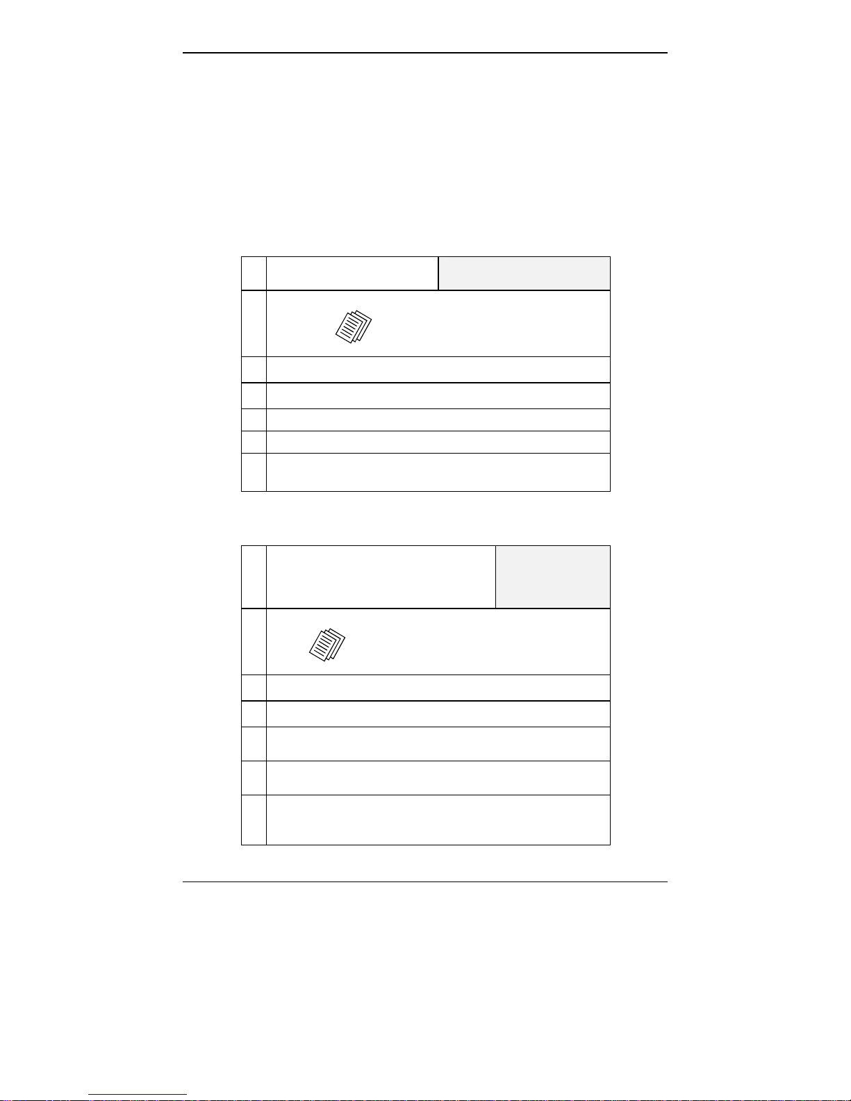
MultiVOIP Startup Tasks
Task Summary
Collecting Phone/IP
Details ( vital! )
Placement
Command/Control
Computer Setup:
Specs & Settings
The MultiVOIP must be configured to
interface with your particular phone
system and IP network. To do so,
certain details must be known about
those phone and IP systems.
Decide where you’ll mount the voip.
Some modest minimum specifications
must be met. A data connection to the
MultiVOIP unit (whether via serial
port, USB2.0-with-adaptor, or webbased) must be made.
Hookup Connect power, phone, and data cables
per diagram.
Software Installation This is the configuration program.
It’s a standard Windows software
installation.
Phone/IP Starter
Configuration
You will enter phone numbers and IP
addresses. You’ll use default parameter
values where possible to get the system
running quickly.
Use “Config Info CheckList” (page 24).
Phonebook Starter
Configuration
The phonebook is where you specify
how calls will be routed. To get the
system running quickly, you’ll make
phonebooks for just two voip sites.
Connectivity Test You’ll find out if your voip system can
carry phone calls between two sites.
That means you’re up and running!
Troubleshooting Detect and remedy any problems that
might have prevented connectivity.
21
Page 22
Gathering Phone/IP Details MultiVOIP Quick Start Instructions
Phone/IP Details *Absolutely Needed*
Before Starting the Installation
The MultiVOIP will interface with both the IP network and the phone
system. You must gather information about the IP network and about
the phone system so that the MultiVOIP can be configured to operate
with them properly. A summary of this configuration information
appears on page 24 (“Config Info CheckList”).
Gather IP Information
Ask your computer network
administrator.
#
• IP Address
• IP Mask
• Gateway
• Domain Name Server (DNS) Info (optional)
• Determine whether or not 802.1p Packet Prioritization
will be used.
IP Network Parameters:
Record for each VOIP Site
in System
Gather Telephone Information
ISDN-BRI Phone Parameters
Ask phone company or
telecom manager.
#
• In which country is this voip installed?
ISDN-BRI Telephony Interface Parameters:
Record them for this VOIP Site
Info needed to operate:
all MultiVOIP models.
Needed for:
MVP810ST
MVP410ST
• Which operator (switch type) is used?
• What type of line coding use required,
• Determine which BRI ports will be network side and
• If you are connecting the MultiVOIP to network
A-law or u-law?
which BRI ports will be terminal side.
equipment with a “U” interface, an NT1 device must
be connected between them.
22
Page 23
MultiVOIP Quick Start Instructions Gathering Phone/IP Details
Phone/IP Details Often Needed/Wanted
Obtain Email Address for VOIP (for email call log reporting)
required if log reports of
VOIP call traffic
are to be sent by email
SMTP Parameters
Preparation Task:
Ask Mail Server
administrator to set up
email account (with
password) for the
MultiVOIP unit itself.
Be sure to give a unique
identifier to each
individual MultiVOIP
unit.
Get the IP address of the
mail server computer, as
well.
Optional
To: I .T. D ep ar tm ent
re: email accoun t for VOIP
voip-unit2@biggytech.com
23
Page 24

Gathering Phone/IP Details MultiVOIP Quick Start Instructions
Config Info CheckList
Type of Config Info Gathered
MultiVOIP
Configuration screen
on which to enter
Config Info
√
IP info for voip unit
● IP address
● Gateway
● DNS IP (if used)
● 802.1p Prioritization (if used)
ISDN Layer 1 Interface
(Choices: Network, Terminal)
Clock Master Status (only a channel
designated as Terminal can be used
as the Clock Master)
Switch Info
● Country ● Operator
● TEI Assignment
● A-Law or Mu-Law?
Calling Party Number Type ISDN BRI Parameters
Called Party Number Type & Plan ISDN BRI Parameters
Country Code Regional Parameters
Email address for voip
(optional)
Reminder: Be sure to Save Setup after entering configuration values.
Ethernet/IP Parameters
ISDN BRI Parameters
ISDN BRI Parameters
ISDN BRI Parameters
SMTP Parameters
24
Page 25

MultiVOIP Quick Start Instructions Gathering Phone/IP Details
Identify Remote VOIP Site to Call
When you’re done installing the MultiVOIP, you’ll want to confirm that
it is configured and operating properly. To do so, it’s good to have
another voip that you can call for testing purposes. You’ll want to
confirm end-to-end connectivity. You’ll need IP and telephone
information about that remote site.
If this is the very first voip in the system, you’ll want to coordinate the
installation of this MultiVOIP with an installation of another unit at a
remote site.
Identify VOIP Protocol to be Used
Will you use H.323, SIP, or SPP? Each has advantages and
disadvantages. Although it is possible to mix protocols in a single
VOIP system, it is highly desirable to use the same VOIP protocol for
all VOIP units in the system. SPP is a non-standard protocol developed
by Multi-Tech. SPP is not compatible with the “Proprietary” protocol
used in Multi-Tech’s earlier generation of voip gateways.
25
Page 26

Voip Placement & PC Settings MultiVOIP Quick Start Instructions
Placement
Mount your MultiVOIP in a safe and convenient location where cables
for your network and phone system are accessible. Rack-mounting
instructions are in Chapter 3: Mechanical Installation & Cabling of the User
Guide.
Command/Control Computer Setup (Specs & Settings)
The computer used for command and control of the MultiVOIP
(a) must be an IBM-compatible PC,
(b) must use a Microsoft operating system,
(c) must be connected to your local network (Ethernet) system, and
(d) must have an available serial COM port.
The configuration tasks and control tasks the PC will have to do with
the MultiVOIP are not especially demanding. Still, we recommend
using a reasonably new computer. The computer that you use to
configure your MultiVOIP need not be dedicated to the MultiVOIP
after installation is complete.
COM port on controller PC. You’ll need an available COM port on the
controller PC. You’ll need to know which COM port is available for use
with the MultiVOIP (COM1, COM2, etc.). If your command computer
has only USB2.0 ports and no serial ports, you will need a USB2.0-toserial adaptor.
Work-Around Allowing Use of Web GUI Only. The default IP
address of the MultiVOIP unit as shipped from the factory is
192.168.3.143. By installing the up-to-date Java program from the
MultiVOIP CD, temporarily resetting the IP address of the command
computer to 192.168.3.x, and connecting both to the same physical
Ethernet network, the MultiVOIP unit’s built-in- web GUI can be
contacted and its IP address can be set as needed. If this is done, all
subsequent configuration can be done using the MultiVOIP web GUI
and the command computer would not need a serial COM port.
Therefore, in the case of a computer lacking a serial port, no USB2.0-toserial adaptor would be needed. However, under such an
arrangement, the command computer would remain unable to use the
MultiVOIP Windows GUI because contact with the Windows GUI
requires either a COM port or the USB2.0-to-serial adaptor
arrangement. (If you use this work-around, you must be sure to re-set
your command PC to its original IP address afterwards.)
26
Page 27
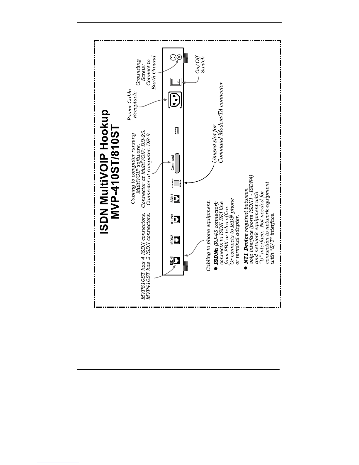
MultiVOIP Quick Start Instructions Quick Hookups
Hookup for MVP410ST & MVP810ST
27
Page 28

Software Installation MultiVOIP Quick Start Instructions
Load MultiVOIP Control Software onto PC
For more details, see Chapter 4: Software Installation in this manual.
1. MultiVOIP must be properly cabled. Power must be turned on.
2. Insert MultiVOIP CD into drive. Allow 10-20 seconds for Autorun to
start. If Autorun fails, go to
My Computer | CD ROM drive | Open. Click Autorun icon.
3. At first dialog box, click Install Software.
4. At ‘welcome’ screen, click Next.
5. Follow on-screen instructions. Accept default program folder
location and click Next.
6. Accept default icon folder location. Click Next. Files will be copied.
7. Select available COM port on command/control computer.
8. At completion screen, click Finish.
9. At the prompt “Do you want to run MultiVOIP Configuration?,”
click No. Software installation is complete.
28
Page 29

MultiVOIP Quick Start Instructions Phone/IP Starter Config.
Phone/IP Starter Configuration
For full details, see the Technical Configuration chapter of this manual.
1. Open MultiVOIP program: Start | MultiVOIP xxx | Configuration.
2. Go to Configuration | Ethernet/IP. Enter the IP parameters for your
voip site. Activate Packet Prioritization (802.1p) if desired. If you use a
Domain Name Server (DNS), specify its IP address. If DNS is used, you
can activate the Service Record (SRV) feature. For details, see the
“Technical Configuration” chapter of the User Guide.
3. Do you want to configure and operate the MultiVOIP unit using the
web browser GUI? (It has the same functionality as the local
Windows GUI, but offers remote access.)
If NO, skip to step 5.
If YES, continue with step 4.
29
Page 30

Phone/IP Starter Config. MultiVOIP Quick Start Instructions
4. Web Browser GUI Setup (Optional). To do configuration and
operation procedures using the web browser GUI, you must first set
it up. To do so, follow these steps. (The browser used must be
Internet Explorer 6.0 or above; or Netscape 6.0 or above; or FireFox
1.0 or above.)
A. Be sure an IP address has
been assigned to the
MultiVOIP unit (this must be
done in the MultiVOIP
Windows GUI).
E. Open web browser.
(Note: The PC being used must
be connected to and have an IP
address on the same IP network
that the voip is on.)
B. Save Setup in Windows GUI. F. Browse to IP address of
MultiVOIP unit.
C. Close the MultiVOIP
Windows GUI.
G. If username and password
have been established, enter
them when prompted by
voip.
D. Install Java program from
MultiVOIP product CD.
(Must be Java Runtime
Environment 1.4.2_01 or above.)
NOTE: Required on first use of
Web Browser GUI only.
Need more
info?
See “Web Browser Interface” in Operation &
Maintenance chapter of User Guide.
H. Use web browser GUI to
configure or operate voip.
Once you’ve begun using the web browser GUI, you can go back
to the MultiVOIP Windows GUI at any time. However, you must
log out of the web browser GUI before using the MultiVOIP
Windows GUI.
30
Page 31

MultiVOIP Quick Start Instructions Phone/IP Starter Config.
Phone/IP Starter Configuration (continued)
5. Go to Configuration | Voice/Fax. Select Coder | “Automatic.” At
the right-hand side of the dialog box, click OK. If you know any
specific parameter values that will apply to your system, enter them.
Click Copy Channel. Select Copy to All. Click Copy. At main
Voice/Fax Parameters screen, click OK to exit from the dialog box.
6. Enter telephone system information.
Go to Configuration | ISDN BRI.
Enter parameters obtained from phone company or PBX
administrator.
If the voip is connected to BRI extensions of a PBX or a phone
company, then select "Terminal"
in the ISDN BRI Parameters screen.
If the voip is connected to ISDN terminal adapters and/or ISDN
phones, then select "Network"
in the ISDN BRI Parameters screen.
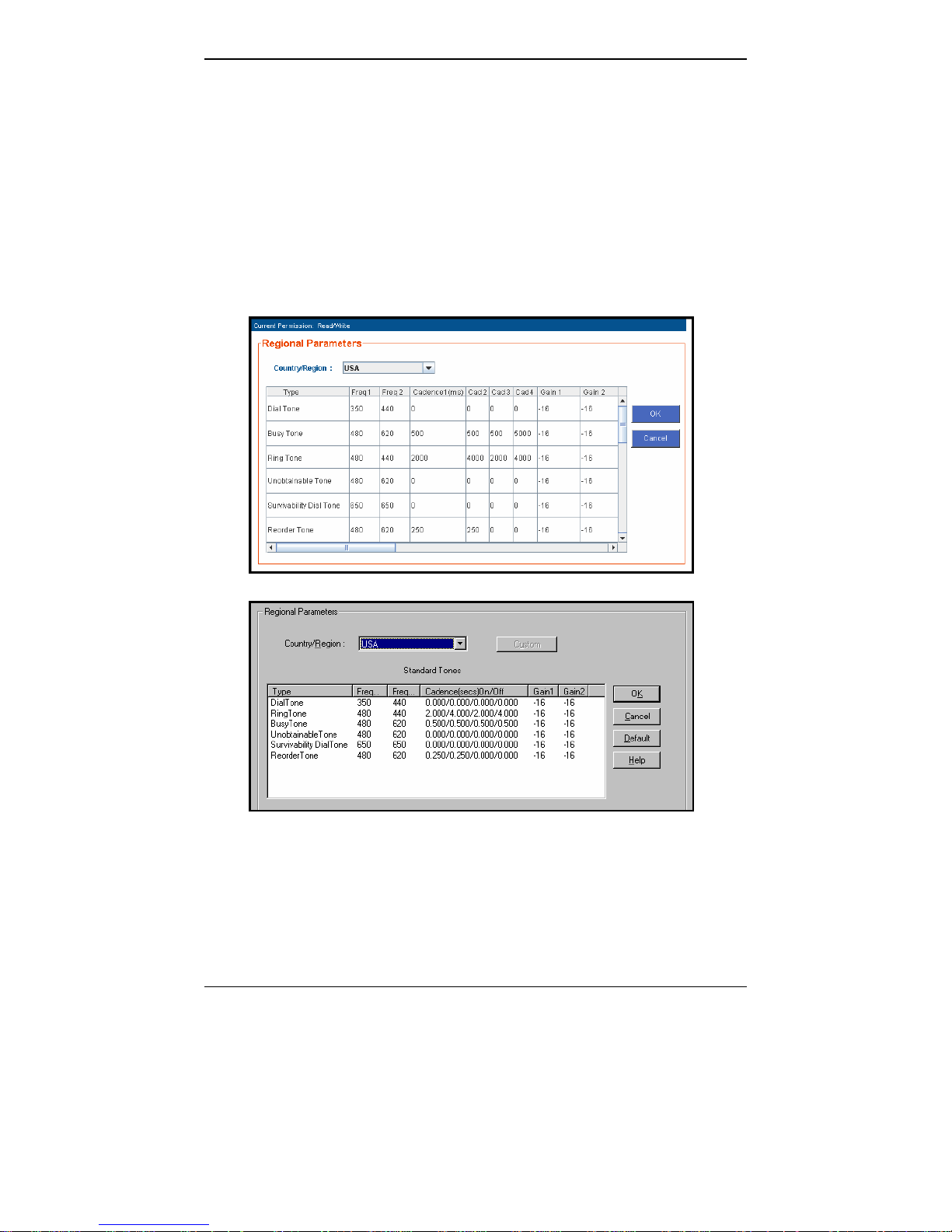
7. Go to Configuration | Regional Parameters. Select the
Country/Region that fits your situation. Click OK and confirm.
Click OK to exit from the dialog box.
8. Go to Configuration | Regional Parameters. In the Country
Selection for Built-In Modem field (drop-down list), select the
country that best fits your situation. (This may not be the same as
your selection for the Country/Region field. The selections in the
Country Selection for Built-In Modem field entail more detailed
groupings of telephony parameters than do the Country/Region
values.)
9. Do you want the phone-call logs produced by the MultiVOIP to be
sent out by email (to your Voip Administrator or someone else)?
If NO, skip to step 11.
If YES, continue with step 10.
10. Go to Configuration | SMTP.
SMTP lets you send phone-call log records to the Voip Administrator
by email. Select Enable SMTP.
You should have already obtained an email address for the
MultiVOIP itself (this serves as the origination email account for
email logs that the MultiVOIP can email out automatically).
Enter this email address in the “Login Name” field.
Type the password for this email account.
Enter the IP address of the email server where the MultiVOIP’s email
account is located in the “Mail Server IP Address” field.
31
Page 32

Phone/IP Starter Config. MultiVOIP Quick Start Instructions
Typically the email log reports are sent to the Voip Administrator
but they can be sent to any email address. Decide where you want
the email logs sent and enter that email address in the “Recipient
Address” field.
Whenever email log messages are sent out, they must have a
standard Subject line. Something like “Phone Logs for Voip N” is
useful. If you have more than one MultiVoip unit in the building,
you’ll need a unique identifier for each one (select a useful name or
number for “N”). In this “Subject” field, enter a useful subject title for
the log messages.
In the “Reply-To Address” field, enter the email address of your Voip
Administrator.
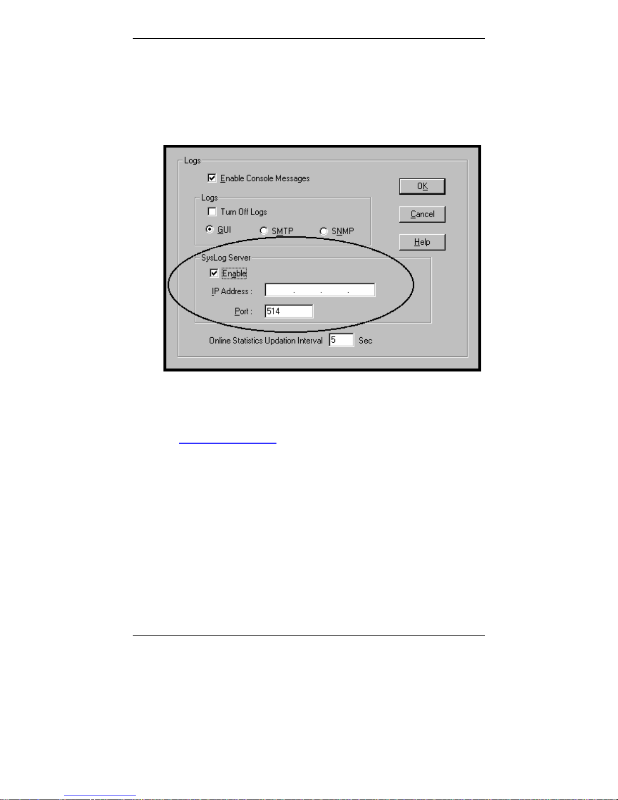
11. Go to Configuration | Logs.
Select “Enable Console Messages.”
To allow log reports by email (if desired), click SMTP. Click OK.
To do logging with a SysLog client program, click on “SysLog Server
– Enable” in the Logs screen. To implement this function, you must
install a SysLog client program. For more info, see the “SysLog
Server Functions” section of the Operation & Maintenance chapter of
the
User Guide.
32
Page 33

MultiVOIP Quick Start Instructions Phone/IP Starter Config.
Phone/IP Starter Configuration (continued)
12. Enable premium (H.450) telephony features.
Go to Supplementary Services. Select any features to be used.
For Call Hold, Call Transfer, & Call Waiting, specify the key sequence
that the phone user will press to invoke the feature. For Call Name
Identification, specify the allowed name types to be used and a callerid descriptor.
If Call Forwarding is to be used, enable this feature in the
Add/Edit Inbound Phone Book screen.
After making changes, click on OK in the current configuration
screen before moving on to the next configuration screen.
13.
RADIUS Support. If you intend to use a RADIUS server for billing or
other accounting purposes, enter the server information in the
RADIUS screen.
14.
STUN Support. If you are using the SIP protocol with the UDP
transmission protocol, and if you want the MultiVOIP to operate
behind a NAT (Network Address Translation server) using the STUN
protocol (Simple Traversal of UDP through NAT), enable this feature
in the NAT Traversal screen. You must also specify the IP address
(etc.) of the STUN server you will use. The STUN server could be a
local device or it could be a public STUN server accessible on the
Internet.
15.
Traffic Control. If you intend to use a traffic control server, go to Call
Signaling and open the screen for the voip protocol you will use
(H.323, SIP, or SPP). For H.323, you can specify a primary and
alternate gatekeepers; for SIP, a primary and alternate proxy servers;
for SPP, a primary and alternate registrar gateways.
If the voip protocol is SIP, note that a separate username (number
only) and password can be specified for each voip channel.
16. Go to Save Setup | Save and Reboot. Click OK. This will save the
parameter values that you have just entered.
The MultiVOIP’s “BOOT” LED will light up while the configuration
file is being saved and loaded into the MultiVOIP. Don’t do anything
to the MultiVOIP until the “BOOT “LED is off (a loss of power at this
point could cause the MultiVOIP unit to lose the configuration
settings you have made).
END OF PROCEDURE.
33
Page 34

Phonebook Starter Config. MultiVOIP Quick Start Instructions
Phonebook Starter Configuration (with remote voip)
If the topic of voip phone books is new to you, it may be helpful to read
the PhoneBook Tips section (page 41) before starting this procedure.
To do this part of the quick setup, you need to know of another voip
that you can call to conduct a test. It should be at a remote location,
typically somewhere outside of your building. You must know the
phone number and IP address for that site. We are assuming here that
the MultiVOIP will operate in conjunction with a PBX.
You must configure both the Outbound Phonebook and the Inbound
Phonebook. A starter configuration only means that two voip locations
will be set up to begin the system and establish voip communication.
Outbound Phonebook
1. Open the MultiVOIP program.
( Start | MultiVOIP xxx | Configuration )
2. Go to Phone Book | Outbound Phonebook
| Add Entry.
3. On a sheet of paper, write down the calling code of the remote voip
(area code, country code, city code, etc.) that you’ll be calling.
Follow the example that best fits your situation.
North America,
Long-Distance Example
Technician in Seattle (area
206) must set up one voip
there, another in Chicago
(area 312, downtown).
Answer: Write down 312.
Euro, National Call
Example
Technician in central
London (area 0207) to set
up voip there, another in
Birmingham (area 0121).
Answer: write down 0121.
Euro, International Call Example
Technician in Rotterdam (country 31; city 010) to
set up one voip there, another in Bordeaux
(country 33; area 05).
Answer: write down 3305.
34
Page 35

MultiVOIP Quick Start Instructions Phonebook Starter Config.
4. Suppose you want to call a phone number outside of your building
using a phone station that is an extension from your PBX system (if
present). What digits must you dial? Often a “9” or “8” must be
dialed to “get an outside line” through the PBX (i.e., to connect to the
PSTN). Generally, “1 “or “11” or “0” must be dialed as a prefix for
calls outside of the calling code area (long-distance calls, national
calls, or international calls).
On a sheet of paper, write down the digits you must dial before you
can dial a remote area code.
North America,
Long-Distance Example
Seattle-Chicago system.
Seattle voip works with
PBX that uses “8” for all
voip calls. “1” must
immediately precede area
code of dialed number.
Answer: write down 81.
Euro, National Call
Example
London/Birming. system.
London voip works with
PBX that uses “9” for all
out-of-building calls
whether by voip or by
PSTN. “0” must
immediately precede area
code of dialed number.
Answer: write down 90.
Euro, International Call Example
Rotterdam/Bordeaux system.
Rotterdam voip works with PBX where “9” is
used for all out-of-building calls. “0” must
precede all international calls.
Answer: write down 90.
35
Page 36

Phonebook Starter Config. MultiVOIP Quick Start Instructions
5. In the “Destination Pattern” field of the Add/Edit Outbound
Phonebook screen, enter the digits from step 4 followed by the digits
from step 3.
North America,
Long-Distance Example
Seattle-Chicago system.
Answer: enter 81312 as
Destination Pattern in Outbound
Phone-book of
Seattle voip.
Euro, National Call
Example
London/Birming. system.
Leading zero of
Birmingham area code is
dropped when combined
with national-dialing
access code. (Such
practices vary by country.)
Answer: enter 90121 as
Destination Pattern in Outbound
Phonebook of
London voip.
Not 900121.
Euro, International Call Example
Rotterdam/Bordeaux system.
Answer: enter 903305 as Destination Pattern in
Outbound Phonebook of Rotterdam voip.
36
Page 37

MultiVOIP Quick Start Instructions Phonebook Starter Config.
6. In the “Remove Prefix” field, enter the initial PBX access digit (“8” or
“9”).
North America,
Long-Distance Example
Seattle-Chicago system.
Answer: enter 8 in “Remove
Prefix” field of
Seattle Outbound
Phonebook.
Euro, National Call
Example
London/Birming. system.
Answer: enter 9 in “Remove
Prefix” field of
London Outbound
Phonebook.
Euro, International Call Example
Rotterdam/Bordeaux system.
Answer: enter 9 in “Remove Prefix” field of Outbound
Phonebook for Rotterdam voip.
Some PBXs will not ‘hand off’ the “8” or “9” to the voip. But for those PBX
units that do, it’s important to enter the “8” or “9” in the “Remove Prefix”
field in the Outbound Phonebook. This precludes the problem of having to
make two inbound phonebook entries at remote voips, one to account for
situations where “8” is used as the PBX access digit, and another for when
“9” is used.
7. In the “Protocol Type” field group, select the voip protocol that you
will use (H.323, SIP, or SPP). Use the appropriate screen under
Configuration | Call Signaling to configure the voip protocol in
detail.
8. Click OK. to exit from the Add/Edit Outbound Phonebook screen.
37
Page 38

Phonebook Starter Config. MultiVOIP Quick Start Instructions
Inbound Phonebook
1. Open the MultiVOIP program.
( Start | MultiVOIP xxx | Configuration )
2. Go to Phone Book | Inbound Phonebook | Add Entry.
3. In the “Remove Prefix” field, enter your local calling code (area code,
country code, city code, etc.) preceded by any other “access digits”
that are required to reach your local site from the remote voip
location (think of it as though the call were being made through the
PSTN – even though it will not be).
North America,
Long-Distance Example
Seattle-Chicago system.
Seattle is area 206. Chicago
employees must dial 81
before dialing any Seattle
number on the voip system.
Answer: 1206 is prefix to be
removed by local
(Seattle) voip.
Euro, National Call
Example
London/Birming. system.
Inner London is 0207 area.
Birmingham employees must
dial 9 before dialing any
London number on the voip
system.
Answer: 0207 is prefix to be
removed by local
(London) voip.
Euro, International Call Example
Rotterdam/Bordeaux system.
Rotterdam is country code 31, city code 010. Bordeaux
employees must dial 903110 before dialing any
Rotterdam number on the voip system.
Answer: 03110 is prefix to be removed by local
(Rotterdam) voip.
38
Page 39

MultiVOIP Quick Start Instructions Phonebook Starter Config.
4. In the “Add Prefix” field, enter any digits that must be dialed from
your local voip to gain access to the PSTN.
North America,
Long-Distance Example
Seattle-Chicago system.
On Seattle PBX, “9” is used to
get an outside line.
Answer: 9 is prefix to be
added by local
(Seattle) voip.
Euro, National Call
Example
London/Birming. system.
On London PBX, “9” is used
to get an outside line.
Answer: 9 is prefix to be
added by local
(London) voip.
Euro, International Call Example
Rotterdam/Bordeaux system.
On Rotterdam PBX, “9” is used to get an outside line.
Answer: 9 is prefix to be added by local (Rotterdam)
voip.
5. In the “Channel Number” field, enter “Hunting.” A “hunting” value
means the voip unit will assign the call to the first available channel.
If desired, specific channels can be assigned to specific incoming calls
(i.e., to any set of calls received with a particular incoming dialing
pattern).
39
Page 40

Phonebook Starter Config. MultiVOIP Quick Start Instructions
6. In the “Description” field, it is useful to describe the ultimate
destination of the calls. For example, in a New York City voip
system, “incoming calls to Manhattan office,” might describe a
phonebook entry, as might the descriptor “incoming calls to NYC
local calling area.” The description should make the routing of calls
easy to understand. (40 characters max.)
North America,
Long-Distance Example
Seattle-Chicago system.
Possible Description:.
Free Seattle access, all
employees
Euro, National Call
Example
London/Birming. system.
Possible Description:.
Local-rate London access,
all empl.
Euro, International Call Example
Rotterdam/Bordeaux system.
Possible Description:. Local-rate Rotterdam access, all
empl.
7. Repeat steps 2-6 for each inbound phonebook entry. When all entries
are complete, go to step 8.
8. Click OK to exit the inbound phonebook screen.
9. Click on Save Setup. Highlight Save and Reboot. Click OK.
Your starter inbound phonebook configuration is complete.
40
Page 41

Phonebook Tips MultiVOIP Quick Start Instructions
Phonebook Tips
Preparing the phonebook for your voip system is a complex task that, at
first, seems quite daunting. These tips may make the task easier.
1.
Use Dialing Patterns, Not Complete Phone Numbers. You will not
generally enter complete phone numbers in the voip phonebook.
Instead, you’ll enter “destination patterns” that involve area codes and
other digits. If the destination pattern is a whole area code, you’ll be
assigning all calls to that area code to go to a particular voip which has
a unique IP address. If your destination pattern includes an area code
plus a particular local phone exchange number, then the scope of calls
sent through your voip system will be narrowed (only calls within that
local exchange will be handled by the designated voip, not all calls in
that whole area code). In general, when there are fewer digits in your
destination pattern, you are asking the voip to handle calls to more
destinations.
2.
The Four Types of Phonebook Digits Used. Important!
“Destination patterns” to be entered in your phonebook will generally
consist of:
(a) calling area codes,
(b) access codes,
(c) local exchange numbers, and
(d) specialized codes.
Although voip phonebook entries may look confusing at first, it’s
useful to remember that all the digits in any phonebook entry must be
of one of these four types.
(a)
calling area codes. There are different names for these around the
world: “area codes,” “city codes,” “country codes,” etc. These codes,
are used when making non-local calls. They always precede the phone
number that would be dialed when making a local call.
41
Page 42

Phonebook Tips MultiVOIP Quick Start Instructions
(b) access codes. There are digits (PSTN access codes) that must be
dialed to gain access to an operator, to access the publicly switched
‘long-distance’ calling system(North America), to access the publicly
switched ‘national’ calling system (Europe and elsewhere), or to access
the publicly switched ‘international’ calling system (worldwide).
There are digits (PBX access codes) that must be dialed by phones
connected to PBX systems or key systems. Often a “9” must be dialed
on a PBX phone to gain access to the PSTN (‘to get an outside line’).
Sometimes “8” must be dialed on a PBX phone to divert calls onto a
leased line or to a voip system. However, sometimes PBX systems are
‘smart’ enough to route calls to a voip system without a special access
code (so that “9” might still be used for all calls outside of the building).
There are also digits (special access codes) that must be dialed to gain
access to a particular discount long-distance carrier or to some other
closed or proprietary telephone system.
(c)
local exchange numbers. Within any calling area there will be many
local exchange numbers. A single exchange may be used for an entire
small town. In cities, an exchange may be used for a particular
neighborhood (although exchanges in cities do not always cover easily
discernible areas). Organizations like businesses, governments,
schools, and universities are also commonly assigned exchange
numbers for their exclusive use. In some cases, these organizationalassigned exchanges can become non-localized because the exchange is
assigned to one facility and linked, by the organization’s private
network, to other sometimes distant locations.
(d)
specialized codes. Some proprietary voip units assign, to sites and
phone stations, numbers that are not compatible with PSTN
numbering. This can also occur in PBX or key systems. These
specialized numbers must be handled on a case-by-case basis.
3.
Knowing When to Drop Digits. Example
When calling area codes and
access codes are used in
combination, a leading “1” or “0”
must sometimes be dropped.
Phonebook Entry
Area code for Inner London is
listed as “0207.” However, in
international calls the leading
“0” is dropped.
U.K.
Country
Code
International
Access Code
Leading Zero
Dropped from
Area Code
42
Page 43

MultiVOIP Quick Start Instructions Phonebook Tips
4.
Using a Comma. Detail
Commas are used in telephone
dialing strings to indicate a pause
to allow a dial tone to appear
(common on PBX and key
systems). Commas may be used
only in the “Add Prefix” field of
the Inbound Phonebook.
5.
Ease of Use. The phonebook setup determines how easy the voip
system is to use. Generally, you’ll want to make it so dialing a voip call
is very similar to dialing any other number (on the PSTN or through the
PBX).
6.
Avoid Unintentional Calls to Official/Emergency Numbers. Dialing a
voip call will typically be somewhat different than ordinary dialing.
Because of this, it’s possible to set up situations, quite unwittingly,
where phone users may be predisposed to call official numbers without
intending to do so. Conversely, a voip/PBX system might also make it
difficult to place an official/emergency call when one intends to do so.
Study your phonebook setup and do some test-dialing on the system to
avoid these pitfalls.
, = 1-second pause
in many PBX systems
(not needed in all)
7.
Inbound/Outbound Pattern Matching. In general, the Inbound
Phonebook entries of the local voip unit will match the Outbound
Phonebook entries of the remote voip unit. Similarly, the Outbound
Phonebook entries of the local voip unit will match the Inbound
Phonebook entries of the remote voip unit. There will often be nonmatching entries, but it’s nonetheless useful to notice the matching
between the phonebooks.
8.
Simulating Network in-lab/on-benchtop. One common method of
configuring a voip network is to set up a local IP network in a lab,
connect voip units to it, and perhaps have phones connected on channel
banks to make test calls.
43
Page 44

Phonebook Tips MultiVOIP Quick Start Instructions
NOTES
44
Page 45

MultiVOIP Quick Start Instructions Phonebook Example
Phonebook Example
Boise Office
PBX System.
Main Number:
333-2700
Inbound Phonebook
Each Inbound P honebook contai ns
two entries. The first entry (4 digits)
specifies how incoming calls from the
other voip sites w ill be handled if
they g o out ont o the local PSTN.
Essentially, all those calls come to the
receiving voip with a pattern
beginni ng wi th
voip removes those four digits
becau se t hey a ren ’t need ed w hen
dialing locally. The local voip
att aches a “ 9” at th e begi nni ng of t he
number to get an outside line. The
PBX then completes the call to the
PSTN .
The second
(1 digit) is for receiving calls from
com pan y em pl oy ees in th e ot her tw o
cities. The out-of-town empl oyee
simp ly d ial s 3 d igit s. The fir st of t he
thr ee d igi ts is un iquel y used at each
sit e and so act s as a desti nati on
pattern (Boise exten sions are 7xx,
Sant a Fe ext ensi on s 2xx, Flag staf f
ext ensi ons 6x x).
Th e lo cal v oi p sees t he p att ern in it s
inbou nd phone book and notes t he
first digit (here either 2, 5, or 6).
To make the match, this first digit,
2, 5, or 6 is p ut i n t he “ Remov e Prefi x”
field. This first digit must then be
add ed back once ag ain so t hat the
voip will send all three digits to the
PBX. The PBX can then d ial t he
specific extension identified by the
t hree- di gi t n um ber.
Area: 208
90 extensions
204.16.49.73
24-Channel
Digital VoIP
(MVP2410)
1+area code . The local
Inbound Pho nebo ok en tr y
Flagstaff Office
Area: 520
204.16.49.75
8-Channel
Analog VoIP
(MVP810)
PSTN
One Common Situation
Voip Example. This company has offices in three
d i ff eren t ci ti es. Th e PBX un it s al l oper ate al i k e.
N ot abl y, t hey al l g iv e access to ou tsi de l i nes u si ng
“ 9.” Th ey al l ar e ‘ smar t’ enou gh t o i den t i fy vo i p cal ls
w it hou t u sing a speci al access d ig i t (“ 8” i s used in
som e syst ems) . Fi n al ly , t he sy stem oper ates so t h at
emp l oyees i n an y o ff i ce can d ial emp loy ees in an y
other offi ce using only three digits. Here are the
p ho nebo ok s need ed fo r t hat syst em .
Santa Fe Office
Area: 505
204.16.49.74
8-Channel
Analog VoIP
(MVP810)
IP
Network
Each
pairs of entries, two entries for each
r em ot e sit e. Wh enev er an ou t- of -t ow n
empl oy ee di als a 12- d i git nu mb er
beginni ng wi th the listed 5-d igit
d esti nat ion pat t er n (9+ 1+ ar ea code) of
ano t her comp any l ocat ion, the PBX
ha n d s th e cal l t o t he v oi p sy stem . Th e
local voip strips off the “ 9” and directs
the call to the IP address of the remote
voip . The remot e v oip r eceiv es t he call
an d h an ds i t t o i ts PBX. Th e PBX t hen
completes the call to the PSTN .
Th e one- d ig i t
patterns pertain to 3-digit calling
bet w een co mp any emp l oy ees.
PBX System.
Main Number:
444-3200
PSTN
Outbound Phonebook
Outbound
40 extensions
cont ains t wo
destination
PBX System.
Main Number:
777-5600
30 extensions
PSTN
45
Page 46

Phonebook Example MultiVOIP Quick Start Instructions
Voip Sites with Phonebooks
Boise Office
PBX System.
Main Number:
333-2700
Area: 208
PSTN
90 extensions
Inbound Phonebook Outbound Phonebook
Prefix to
Remove
91208 9, Incoming calls
7 7 i ncoming calls
204.16.49.73
24-Channel
Digital VoIP
(MVP2410)
IP
Network
Santa Fe Voip Santa Fe Voip
Inbound Phonebook Outbound Phonebook
Prefix
to Add
Description
Incoming Calls
to PSTN,
Santa Fe local
calls
to extensions
of company’s
PBX system
in Santa Fe
Prefix to
Remove
91505 9, Incoming calls
2 2 Incoming calls
Tota l
Digits
Prefix to
Remove
Destin.
Pattern
91208 12 none none 204.
7 3 none none 204.
91520 12 none none 204.
6 3 none none 204.
Boise Voip Boise Voip
Prefix
to Add
Description
Incoming Calls
to PSTN,
Boise Area
to extensions
of company’s
PBX system
in Boise
Tota l
Prefix to
Destin.
Digits
Pattern
91505 12 none none
2 3 none none
91520 12 none none 204.
6 3 none none 204.
Remove
Prefix
to AddIPAddr
Santa Fe Office
Prefix
to AddIPAddr
16.49.
73
16.49.
73
16.49.
75
16.49.
75
Description
Outgoing Calls
Outgoing calls
to Boise area
3-digit calls to
Boise
employees
(extensions
700-790)
Outgoing calls
to Flagstaff
area
3-digit calls to
Flagstaff
employees
(extensions
600-630)
PBX System.
Main Number:
444-3200
204.
16.49.
74
204.
16.49.
74
16.49.
75
16.49.
75
Area: 505
204.16.49.74
Analog VoIP
PSTN
Description
Outgoing Calls
Outgoing calls
to Santa Fe
area
3-digit calls to
Santa Fe
employees
(extensions
200 to 240)
Outgoing calls
to Flagstaff
area
3-digit calls to
Flagstaff
employees
(extensions
600-630)
8-Channel
(MVP810)
40 extensio ns
Flagstaff Office
Area: 520
204.16.49.75
8-Channel
Analog VoIP
(MVP810)
PBX System.
Main Number:
777-5600
30 extensions
PSTN
Flagstaff Voip Flagstaff Voip
Inbound Phonebook Outbound Phonebook
Prefix
to Add
Description
Incoming Calls
to PSTN,
Flagstaff local
calls
to extensions
of company’s
PBX system
in Flagstaff
Prefix to
Remove
91520 9 Incoming calls
6 6 Incoming calls
Tota l
Digits
Prefix to
Remove
Destin.
Pattern
91505 12 none none
2 3 none none
91208 12 none none
7 3 none none
Prefix
to AddIPAddr
204.16
.49.74
204.16
.49.74
204.16
.49.73
204.16
.49.73
Description
Outgoing Calls
Outgoing calls
to Santa Fe
area
3-digit calls to
Santa Fe
employees
(extensions
200-240)
Outgoing calls
to Boise area
3-digit calls to
Boise
employees
(extensions
700-790)
46
Page 47

MultiVOIP Quick Start Instructions Phonebook Example
Sample Phonebooks Enlarged
Boise Voip Boise Voip
Inbound Phonebook Outbound Phonebook
Prefix
Prefix to
Remove
91208 9, Incoming calls
7 7 i ncoming calls
to Add
Description
Incoming Calls
to PSTN,
Boise Area
to extensions
of company’s
PBX system
in Boise
Santa Fe Voip Santa Fe Voip
Inbound Phonebook Outbound Phonebook
Prefix to
Remove
91505 9, Incoming calls
2 2 Incoming calls
Prefix
to Add
Destin.
Pattern
91505 12 none none
2 3 none none
91520 12 none none 204.
6 3 none none 204.
Description
Incoming Calls
to PSTN,
Santa Fe local
calls
to extensions
of company’s
PBX system
in Santa Fe
Total
Prefix to
Remove
Prefix
to AddIPAddr
Total
Digits
Prefix to
Remove
Digits
Destin.
Pattern
91208 12 none none 204.
7 3 none none 204.
91520 12 none none 204.
6 3 none none 204.
204.
16.49.
74
204.
16.49.
74
16.49.
75
16.49.
75
Description
Outgoing Calls
Outgoing calls
to Santa Fe
area
3-digit calls to
Santa Fe
employees
(extensions
200 to 240)
Outgoing calls
to Flagstaff
area
3-digit calls to
Flagstaff
employees
(extensions
600-630)
Prefix
to AddIPAddr
16.49.
73
16.49.
73
16.49.
75
16.49.
75
Description
Outgoing Calls
Outgoing calls
to Boise area
3-digit calls to
Boise
employees
(extensions
700-790)
Outgoing calls
to Flagstaff
area
3-digit calls to
Flagstaff
employees
(extensions
600-630)
Flagstaff Voip Flagstaff Voip
Inbound Phonebook Outbound Phonebook
Prefix to
Remove
91520 9 Incoming calls
6 6 Incoming calls
Prefix
to Add
Description
Incoming Calls
to PSTN,
Flagstaff local
calls
to extensions
of company’s
PBX system
in Flagstaff
Total
Prefix to
Destin.
Digits
Pattern
91505 12 none none
2 3 none none
91208 12 none none
7 3 none none
Remove
Prefix
to AddIPAddr
47
204.16
.49.74
204.16
.49.74
204.16
.49.73
204.16
.49.73
Description
Outgoing Calls
Outgoing calls
to Santa Fe
area
3-digit calls to
Santa Fe
employees
(extensions
200-240)
Outgoing calls
to Boise area
3-digit calls to
Boise
employees
(extensions
700-790)
Page 48

Phonebook Example MultiVOIP Quick Start Instructions
Phonebook Worksheet
Voip Location/ID:____________________________
Inbound Phonebook Outbound Phonebook
Prefix
Prefix to
Remove
to Add
Other Details:
Inbound Phonebook Outbound Phonebook
Prefix to
Remove
Description
Incoming Calls
Destin.
Pattern
Voip Location/ID:____________________________
Prefix
Description
to Add
Incoming Calls
Tot al
Digits
Destin.
Pattern
Prefix to
Remove
Tot al
Digits
Prefix
to AddIPAddr
Prefix to
Remove
Description
Outgoing Calls
Prefix
to AddIPAddr
Description
Outgoing Calls
Other Details:
Voip Location/ID:____________________________
Inbound Phonebook Outbound Phonebook
Prefix
Prefix to
Remove
to Add
Description
Incoming Calls
Destin.
Pattern
Tot al
Digits
Prefix to
Remove
Prefix
to AddIPAddr
Description
Outgoing Calls
Other Details:
48
Page 49

MultiVOIP Quick Start Instructions Phonebook Example
Enlarged Phonebook Worksheet
49
Page 50

MultiVOIP Quick Start Instructions Connectivity Test
Connectivity Test
The procedures “Phone/IP Starter Configuration” and “Phonebook
Starter Configuration” must be completed before you can do this
procedure.
1. These connections must be made:
MultiVOIP to local PBX
MultiVOIP to command PC
or telco
MultiVOIP to Internet
2. Inbound Phonebook and Outbound Phonebook must both be set up
with at least one entry in each. These entries must allow for
connection between two voip units.
3. Console messages must be enabled. (If this has not been done
already, go, in the MultiVOIP GUI, to Configuration | Logs and
select the “Console Messages” checkbox.
50
Page 51

MultiVOIP Quick Start Instructions Connectivity Test
4. You now need to free up the COM port connection (currently being
used by the MultiVOIP program) so that the HyperTerminal program
can use it. To do this, you can either (a) click on Connection in the
sidebar and select “Disconnect” from the drop-down box, or (b) close
down the MultiVOIP program altogether.
5. Open the HyperTerminal program.
6. Use HyperTerminal to receive and record console messages from the
MultiVOIP unit. To do so, set up HyperTerminal as follows (setup
shown is for Windows NT4; details will differ slightly in other MS
operating systems):
In the upper toolbar of the HyperTerminal screen, click on
the Properties button.
In the “Connect To” tab of the Connection Properties
dialog box, click on the Configure button.
In the next dialog box, on the “General” tab, set
“Maximum Speed” to 115200 bps.
On the “Connection” tab, set connection preferences to:
Data bits: 8
Parity: none
Stop bits: 1
Click OK twice to exit settings dialog boxes.
51
Page 52

Connectivity Test MultiVOIP Quick Start Guide
7. Make VOIP call.
for ISDN-BRI MultiVOIPs (MVP-410ST/810ST)
in terminal mode;
Make call from an extension of the local PBX to
the voip extension.
8. Read console messages recorded on HyperTerminal.
Console Messages from Originating VOIP. The voip unit that
originates the call will send back messages like that shown below.
[00026975] CAS[0] : RX : ABCD = 1, 1, 1, 1,Pstn State[1]
TimeStamp : 26975
[00027190] CAS[0] : TX : ABCD = 1, 1, 1, 1
[00027190] PSTN: cas seizure detected on 0
[00027440] CAS[0] : TX : ABCD = 0, 0, 0, 0
[00033290] PSTN:call detected on 0 num=17637175662*
[00033290] H323IF[0]:destAddr =
TA:200.2.10.5:1720,NAME:Mounds
View,TEL:17637175662,17637175662
[00033290] H323IF[0]:srcAddr = NAME:New
York,TA:200.2.9.20
[00033440] H323IF [0]:cmCallStateProceeding
[00033500] H323[0]: Remote Information (Q931): MultiVOIP
- T1
[00033565] CAS[0] : TX : ABCD = 1, 1, 1, 1
[00033675] H323IF [0]: MasterSlaveStatus=Slave
[00033675] H323IF[0]:FastStart Setup Not Used
[00033690] CAS[0] : TX : ABCD = 1, 1, 1, 1
[00033755] H323IF[0]: Coder used 'g7231'
[00033810] PSTN:pstn call connected on 0
52
Page 53

MultiVOIP Quick Start Instructions Connectivity Test
Console Messages from Terminating VOIP. The voip unit connected
to the phone where the call is answered will send back messages like
that shown below.
[00170860] H323[0]: New incoming call
[00170860] PSTNIF : Placing call on channel 0 Outbound
digit 7175662
[00170885] CAS[0] : TX : ABCD = 1, 1, 1, 1
[00171095] H323IF [0]: MasterSlaveStatus=Master
[00171105] CAS[0] : RX : ABCD = 1, 1, 1, 1,Pstn State[7]
TimeStamp : 171105
[00171105] H323IF[0]: Coder used 'g7231'
[00171110] H323IF[0]:FastStart Setup Not Used
[00171110] H323IF[0]: Already opened the outgoing logical
channel
[00171110] H323IF[0]: Coder used 'g7231'
[00171315] CAS[0] : RX : ABCD = 0, 0, 0, 0,Pstn State[9]
TimeStamp : 171315
[00172275] PSTN: dialing digit ended on 0
[00172285] PSTN: pstn proceeding indication on 0
[00172995] CAS[0] : RX : ABCD = 1, 1, 1, 1,Pstn State[12]
TimeStamp : 172995
[00173660] CAS[0] : TX : ABCD = 1, 1, 1, 1
[00173760] PSTN:pstn call connected on 0
9. When you see the following message, end-to-end voip connectivity
has been achieved.
PSTN: pstn call connected on X”
“
where x is the number of the voip channel carrying the call
10. If the HyperTerminal messages do not confirm connectivity, go to
the Troubleshooting procedure below.
53
Page 54

Troubleshooting MultiVOIP Quick Start Instructions
Troubleshooting
If you cannot establish connectivity between two voips in the system,
follow the steps below to determine the problem.
1. Ping both MultiVOIP units to confirm connectivity to the network.
2. Verify the telephone connections.
Check cabling. Are connections well seated? To correct
receptacle?
If terminal equipment is connected to the voip, then "Network"
should be selected for that BRI interface in the ISDN BRI
Parameters screen.
Note: Each BRI interface is separately configurable.
If network equipment such as an ISDN BRI PBX or an
ISDN BRI line from a phone company is connected to the voip,
then "Terminal" should be selected for that BRI interface in the
ISDN BRI Parameters screen.
Was the proper country and operator chosen?
Was the proper type of line coding (A-law or u-law) chosen?
3. Verify phonebook configuration.
4. Observe console messages while placing a call. Look for error
messages indi-cating phonebook problems, network problems, voicecoder mismatches, etc.
54
Page 55

Chapter 3: Mechanical Installation
and Cabling
55
Page 56

Mechanical Installation & Cabling MultiVOIP User Guide
Introduction
When the MVP410ST or MVP810ST MultiVOIP units are to be installed
into a rack, two able-bodied persons should participate.
Please read the safety notices before beginning installation.
Safety Warnings
Lithium Battery Caution
A lithium battery on the voice/fax channel board provides backup
power for the timekeeping capability. The battery has an estimated life
expectancy of ten years.
When the battery starts to weaken, the date and time may be incorrect.
If the battery fails, the board must be sent back to Multi-Tech Systems
for battery replacement.
Warning: There is danger of explosion if the battery is incorrectly
replaced.
Safety Warnings Telecom
1. Never install telephone wiring during a lightning storm.
2. This product must be disconnected from power source and telephone
network interface when servicing.
3. This product is to be used with UL and UL listed computers.
4. Never touch uninsulated telephone wires or terminals unless the
telephone line has been disconnected at the network interface.
5. Use caution when installing or modifying telephone lines.
6. Avoid using a telephone (other than a cordless type) during an
electrical storm. There may be a remote risk of electrical shock from
lightning.
7. Do not use a telephone in the vicinity of a gas leak – not even to
report a gas leak.
8. To reduce the risk of fire, use only a UL-listed 26 AWG or larger
telecommunication line cord.
9. Never install a telephone jack in wet locations unless the jack is
specifically designed for wet locations.
56
Page 57

MultiVOIP User Guide Mechanical Installation & Cabling
Unpacking Your MVP-410ST/810ST MultiVOIP
When unpacking your MultiVOIP, check to see that all of the items
shown in Figure 3-1 are included in the box. If any box contents are
missing, contact MultiTech Tech Support at 1-800-972-2439.
Cabling
MultiVOIP
TM
Guide
BootPower
LNK
FDX
Ch1 Ch2
Ch3 Ch4
XMT RCV XMT RCV XMT
XMT RCV XMT RCV
DD
Ch5 Ch6 Ch7 Ch8
XMT XMT RCV XMT
RCVDRCV
RCV
D
ISDN 1 ISDN 2 ISDN 3 ISDN 4
Ethernet
Figure 3-1: Unpacking the MVP-410ST/810ST
57
Page 58

Mechanical Installation & Cabling MultiVOIP User Guide
Rack Mounting Instructions for
MVP410ST & MVP810ST
The MultiVOIPs can be mounted in an industry-standard EIA 19-inch
rack enclosure, as shown in Figure 3-2.
Figure 3-2: Rack-Mounting (MVP410ST or MVP810ST)
58
Page 59

MultiVOIP User Guide Mechanical Installation & Cabling
Safety Recommendations for Rack Installations
Ensure proper installation of the unit in a closed or multi-unit enclosure
by following the recommended installation as defined by the enclosure
manufacturer. Do not place the unit directly on top of other equipment
or place other equipment directly on top of the unit. If installing the
unit in a closed or multi-unit enclosure, ensure adequate airflow within
the rack so that the maximum recommended ambient temperature is
not exceeded. Ensure that the unit is properly connected to earth
ground by verifying that it is reliably grounded when mounted within
a rack. If a power strip is used, ensure that the power strip provides
adequate grounding of the attached apparatus.
When mounting the equipment in the rack, make sure mechanical
loading is even to avoid a hazardous condition, such as loading heavy
equipment in rack unevenly. The rack used should safely support the
combined weight of all the equipment it supports.
Ensure that the mains supply circuit is capable of handling the load of
the equipment. See the power label on the equipment for load
requirements (full specifications for MultiVOIP models are presented in
chapter 1 of this manual).
Maximum ambient temperature for the unit is 60 degrees Celsius (140
degrees Fahrenheit) at 20-90% non-condensing relative humidity. This
equipment should only be installed by properly qualified service
personnel. Only connect like circuits. In other words, connect SELV
(Secondary Extra Low Voltage) circuits to SELV circuits and TN
(Telecommunications Network) circuits to TN circuits.
59
Page 60

Mechanical Installation & Cabling MultiVOIP User Guide
19-Inch Rack Enclosure Mounting Procedure
Attaching the MultiVOIP to a rack-rail of an EIA 19-inch rack enclosure
will certainly require two persons. Essentially, the technicians must
attach the brackets to the MultiVOIP chassis with the screws provided,
as shown in Figure 3-3, and then secure unit to rack rails by the
brackets, as shown in Figure 3-4. Because equipment racks vary, screws
for rack-rail mounting are not provided. Follow the instructions of the
rack manufacturer and use screws that fit.
1. Position the right rack-mounting bracket on the MultiVOIP
using the two vertical mounting screw holes.
2. Secure the bracket to the MultiVOIP using the two screws
provided.
3. Position the left rack-mounting bracket on the MultiVOIP
using the two vertical mounting screw holes.
4. Secure the bracket to the MultiVOIP using the two screws
provided.
5. Remove feet (4) from the MultiVOIP unit.
6. Mount the MultiVOIP in the rack enclosure per the rack
manufacture’s mounting procedure.
x
x
Figure 3-3: Bracket Attachment for Rack Mounting
(MVP410ST & MVP810ST)
Figure 3-4: Attaching MultiVOIP to Rack Rail
(MVP410ST & MVP810ST)
60
Page 61

MultiVOIP User Guide Mechanical Installation & Cabling
Cabling Procedure for MVP-410ST/810ST
Cabling involves connecting the MultiVOIP to your LAN and telephone
equipment.
1. Connect the power cord supplied with your MultiVOIP to a live AC
outlet and to the power connector on the back of the MultiVOIP as
shown at top right in Figure 3-5.
ETHERNET
IS D N
COMMAND
10 BASET
Grounding Screw
Ethernet Connection
TA
IS D N 1 ISDN2 IS D N 3 ISDN4
ISD N-B RI Co n nect ion s
ISDN1 & I SDN 2 : M VP41 0S T/8 10ST
ISDN3 & IS DN 4: MVP81 0ST o nly
?
TERMINAL
MODE
NETWORK
MO DE
*
NT1
Device
PBX
* NT1 Device
if PBX has “U” interface.
PSTN
is ne eded
Command Port Connection
Figure 3-5: Cabling for MVP-410ST/810ST
2. Connect the MultiVOIP to a PC by using a DB-25 (male) to DB-9
(female) cable. Plug the DB-25 end of the cable into the Command
port of the MultiVOIP and the other end into the PC serial port. See
Figure 3-5. If your computer has only USB2.0 ports and no serial
ports, you will need a serial-to-USB2.0 adapter.
3. Connect a network cable to the ETHERNET 10BASET connector on
the back of the MultiVOIP. Connect the other end of the cable to your
network.
61
Page 62

Mechanical Installation & Cabling MultiVOIP User Guide
4. Terminal Mode. When a voip ISDN connector is to be connected to a
PBX extension line or to a telco line, select “Terminal” as the
“Layer 1 Interface” in the ISDN Parameters screen. When making
cable connections, an NT1 device will be needed between the
MultiVOIP and the PSTN or between the MultiVOIP and any PBX
with a “U” interface. (For more information, see Appendix B: Cable
Pinouts in this manual.) Connect cables between voip ISDN
connectors and network equipment.
NOTE: In order to operate in Terminal mode, the
network equipment to which you will be
connecting (e.g., PBX) must support D-channel
signaling in its ISDN-S/T interface.
62
Page 63

MultiVOIP User Guide Mechanical Installation & Cabling
Network Mode. When a voip ISDN connector is to be connected to an
ISDN phone station or to an ISDN terminal adapter (TA), select
“Network” as the “Layer 1 Interface” in the ISDN Parameters screen
of the MultiVOIP software. Connect cables between voip ISDN
connectors and phone or TA.
NOTE. Any ISDN phone stations connected to the MVP-
410ST/810ST must provide their own operating
power. That is, the MVP-410ST/810ST does not
supply power for ISDN phone stations.
63
Page 64

Mechanical Installation & Cabling MultiVOIP User Guide
5. Repeat the above step to connect the remaining ISDN telephone
equipment to each ISDN connector on your MultiVOIP. Be aware
that you can assign each ISDN line separately and independently to
either Network mode or Terminal mode. That is, all ISDN lines do
not have to be assigned in to the same operating mode.
ETHERNET
IS D N 1 ISD N2 ISD N 3 ISDN4
ISDN- B RI Co n nect ion s
ISDN1 & I SDN 2 : MVP 41 0ST /810S T
ISDN3 & I SDN 4: MVP 81 0ST on ly
?
TERMINAL
MODE
NETWORK
MO DE
COMMAND
10 BASET
Grounding Scre w
Ethernet Connectio n
*
IS D N
NT1
Device
TA
PBX
* NT1 Device
if P BX has “U” i nterfac e.
PSTN
is ne eded
Command Port Connection
Figure 3-6: ISDN/BRI Voip Connections for GND & Remote
Configuration Modem
6. Ensure that the unit is properly connected to earth ground by
verifying that it is reliably grounded when mounted within a rack.
This can be accomplished by connecting a grounding wire between
the chassis grounding screw (see Figure 3-6) and a metallic object that
will provide an electrical ground.
7. Ensure that the MultiVOIP unit is properly connected to earth
ground.
This can be accomplished by connecting a grounding wire between
the chassis grounding screw (see Figure 3-7) and a connector securely
connected to the ground (GND) of the building’s electrical system.
Ground Connection Details. Ensure that the unit is securely and
permanently connected to an earth ground (GND) with a ground
wire of 18 gauge (18 AWG) or thicker. The ground wire needs to be
installed between the grounding screw on the MultiVOIP chassis and
a permanent earth ground. Whether the MultiVOIP unit is used in a
rack or on a desktop, you must verify that the earth ground
connection is permanent and reliable. In order for the ground
64
Page 65

MultiVOIP User Guide Mechanical Installation & Cabling
connection to be considered permanent, the grounding wire must
connect to the earth ground of the building's electrical wiring system
and the ground connection must use a screw terminal or other
reliable means of fastening. The ground connection must not be as
easily disconnected as, for example, a power cord.
Product
Ground
Screw
MultiVOIP
Unit
Grounding connectors
must be secured
permanently to
product ground screw
and earth ground screw.
Ground
Wire:
Size 18AWG
or thicker
Earth Ground Screw:
Connected to
Permanent Earth Ground
of Building’s
Electrical System
GND
Figure 3-7. Earth Ground Details
8. Turn on power to the MultiVOIP by placing the ON/OFF switch on
the back panel to the ON position. Wait for the Boot LED on the
MultiVOIP to go off before proceeding. This may take a few minutes.
Proceed to Chapter 4 to load the MultiVOIP software.
Proceed to Chapter 4 to load the MultiVOIP software.
65
Page 66

Chapter 4: Software Installation
66
Page 67

MultiVOIP User Guide Software Installation
Introduction
Configuring software for your MultiVOIP entails three tasks:
(1) loading the software onto the PC (this is “Software Installation and
is discussed in this chapter),
(2) setting values for telephony and IP parameters that will fit your
system (this is “Technical Configuration” and it is discussed in Chapter
5), and
(3) establishing “phonebooks” that contain the various dialing patterns
for VOIP calls made to different locations (this is “Phonebook
Configuration” and it is discussed in Chapter 6 for North American
(T1) telephony standards and in Chapter 7 for European (E1) telephony
standards.
Loading MultiVOIP Software onto the PC
The software loading procedure does not present every screen or option
in the loading process. It is assumed that someone with a thorough
knowledge of Windows and the software loading process is performing
the installation.
The MultiVOIP software and User Guide are contained on the
MultiVOIP product CD. Because the CD is auto-detectable, it will start
up automatically when you insert it into your CD-ROM drive. When
you have finished loading your MultiVOIP software, you can view and
print the User Guide by clicking on the View Manuals icon.
1. Be sure that your MultiVOIP has been properly cabled and that the
power is turned on.
67
Page 68

Software Installation MultiVOIP User Guide
2. Insert the MultiVOIP CD into your CD-ROM drive. The CD should
start automatically. It may take 10 to 20 seconds for the Multi-Tech
CD installation window to display.
If the Multi-Tech Installation CD window does not display
automatically, click My Computer, then right click the CD ROM
drive icon, click Open, and then click the Autorun icon.
3. When the Multi-Tech Installation CD dialog box appears, click the
Install Software icon.
68
Page 69

MultiVOIP User Guide Software Installation
4. A ‘welcome’ screen appears.
Press Enter or click Next to continue.
5. Follow the on-screen instructions to install your MultiVOIP software.
The first screen asks you to choose the folder location of the files of
the MultiVOIP software.
Choose a location and click Next.
69
Page 70

Software Installation MultiVOIP User Guide
6. At the next screen, you must select a program folder location for the
MultiVOIP software program icon.
Click Next. Transient progress screens will appear while files are
being copied.
70
Page 71

MultiVOIP User Guide Software Installation
7. A completion screen will appear.
Click Finish.
8. When setup of the MultiVOIP software is complete, you will be
prompted to run the MultiVOIP software to configure the VOIP.
Software installation is complete at this point. You may proceed with
Technical Configuration now, or not, at your convenience.
Technical Configuration instructions are in the next chapter of this
manual.
71
Page 72

Software Installation MultiVOIP User Guide
Un-Installing the MultiVOIP Configuration
Software
1. To un-install the MultiVOIP configuration software, go to Start |
Programs and locate the entry for the MultiVOIP program. Select
Uninstall.
2. Two confirmation screens will appear. Click Yes and OK when you
are certain you want to continue with the uninstallation process.
72
Page 73

MultiVOIP User Guide Software Installation
3. A special warning message similar to that shown below may appear
concerning the MultiVOIP software’s “.bin” file. Click Yes.
4. A completion screen will appear.
Click Finish.
73
Page 74

Chapter 5: Technical Configuration
74
Page 75

MultiVOIP User Guide Technical Configuration
Configuring the MultiVOIP
There are two ways in which the MultiVOIP must be configured before
operation: technical configuration and phonebook configuration.
Technical Configuration. First, the MultiVOIP must be configured to
operate with technical parameter settings that will match the
equipment with which it interfaces. There are eight types of technical
parameters that must be set.
These technical parameters pertain to
(1) its operation in an IP network,
(2) its operation with telephony equipment,
(3) its transmission of voice and fax messages,
(4) its interaction with SNMP (Simple Network Management Protocol)
network management software (NOTE: SNMP is not currently
supported for BRI MultiVOIPs),
(5) certain telephony attributes that are common to particular nations or
regions,
(6) its operation with a mail server on the same IP network (per SMTP
parameters) such that log reports about VoIP telephone call traffic can
be sent to the administrator by email,
(7) implementing some common premium telephony features (Call
Transfer, Call Hold, Call Waiting, Call ID – “Supplementary Services”),
and
(8) selecting the method by which log reports will be made accessible.
The process of specifying values for the various parameters in these
seven categories is what we call “technical configuration” and it is
described in this chapter.
Phonebook Configuration. The second type of configuration that is
required for the MultiVOIP pertains to the phone number dialing
sequences that it will receive and transmit when handling calls. Dialing
patterns will be affected by both the PBX/telephony equipment and the
other VOIP devices that the MultiVOIP unit interacts with. We call this
“Phonebook Configuration,” and, for analog MultiVOIP units, it is
described in Chapter 6. The Quick Start Guide presents additional
information on phonebook setup.
Local/Remote Configuration. The MultiVOIP is typically configured
locally at first (to establish an IP address for the MultiVOIP unit).
However, you can configure the MultiVOIP remotely from the start by
using the web browser GUI and accessing the MultiVOIP unit at its
default IP address, which is 192.168.3.143. (Remember, however, that
75
Page 76

Technical Configuration MultiVOIP User Guide
192.168.3.143 is the default IP address set at the factory for all
MultiVOIP units. Once you have established contact, you will need to
set up a different IP address that better fits your system.) Changes to
this initial configuration can be done either locally or remotely.
Local configuration is done through a connection between the
“Command” port of the MultiVOIP and the COM port of the computer;
the MultiVOIP configuration program is used.
Remote configuration is done through a connection between the
MultiVOIP’s Ethernet (network) port and a computer connected to the
same network. The computer could be miles or continents away from
the MultiVOIP itself. The MultiVOIP web browser interface program is
the only remote configuration program that is supported for the BRI
MultiVOIP units. There is a GUI screen for SNMP, which relates to the
MultiVoipManager program. However, neither SNMP nor
MultiVoipManager are supported for the BRI MultiVOIP units.
Web Browser Interface. The MultiVOIP web browser GUI gives access
to the same commands and configuration parameters as are available in
the MultiVOIP Windows GUI except for logging functions. When
using the web browser GUI, logging can be done by email (the SMTP
option).
76
Page 77

MultiVOIP User Guide Technical Configuration
7
Functional Equivalence of Interfaces. The MultiVOIP Windows
configuration program is generally used to do the initial configuration
(that is, setting an IP address for the MultiVOIP unit) so that the VOIP
unit can communicate with the the web browser GUI. Management of
the VOIP after that point can be done from either of these two programs
since they both offer essentially the same functionality. Functionally,
the web browser GUI can replace the MultiVOIP configuration
program after the initial configuration is complete (with minor
exceptions, as noted, especially logging).
WARNING: Do not attempt to interface the MultiVOIP unit with
two control programs simultaneously (that is, by
accessing the MultiVOIP Windows configuration
program via the Command Port and the web
browser interface via the Ethernet Port). The results
of using two programs to control a single VOIP
simultaneously would be unpredictable.
7
Page 78

Technical Configuration MultiVOIP User Guide
Local Configuration
This manual primarily describes local configuration with the Windows
GUI. After IP addresses have been set locally using the Windows GUI,
most aspects of configuration (logging functions are an exception) can
be handled through the web browser GUI, as well (see the Operation and
Maintenance chapter of this manual). In most aspects of configuration,
the Windows GUI and web-browser GUI differ only graphically, not
functionally.
Pre-Requisites
To complete the configuration of the
MultiVOIP unit, you must know several
things about the overall system.
Before configuring your MultiVOIP Gateway unit, you must know the
values for several IP and telephone parameters that describe the IP
network system and telephony system (PBX or telco central office
equipment) with which the digital MultiVOIP will interact. If you plan
to receive log reports on phone traffic by email (SMTP), you must
arrange to have an email address assigned to the VOIP unit on the
email server on your IP network. A summary of this configuration
information appears on page 46 (“Config Info CheckList”).
78
Page 79

MultiVOIP User Guide Technical Configuration
IP Parameters
The following parameters must be known about the network (LAN,
WAN, Internet, etc.) to which the MultiVOIP will connect:
Ask your computer network
administrator.
#
• IP Address
• IP Mask
• Gateway
• Domain Name Server (DNS) Info
• If SIP protocol is used, determine whether or not
802.1p Packet Prioritization will be used.
Write down the values for these IP parameters. You will need to enter
these values in the “IP Parameters” screen in the Configuration section
of the MultiVOIP software. You must have this IP information about
every VOIP in the system.
IP Network Parameters:
Record for each VOIP Site
in System
Info needed to operate:
all MultiVOIP models.
ISDN-BRI Telephony Parameters
The following parameters must be known about the PBX or telco
central office equipment to which the analog MultiVOIP will connect:
ISDN-BRI Phone Parameters
Ask phone company or telecom manager.
#
• In which country is this voip installed?
• Which operator (switch type) is used?
• What type of line coding use required,
A-law or u-law?
• Determine which BRI ports will be network side and
which BRI ports will be terminal side.
Write down the values for these ISDN/BRI telephony parameters. You
will need to enter these values in the “ISDN Parameters” screen (ISDNBRI) in the Configuration section of the MultiVOIP software.
ISDN-BRI Telephony Interface Parameters:
Record them for this VOIP Site
79
Page 80

Technical Configuration MultiVOIP User Guide
SMTP Parameters (for email call log reporting)
required if log reports of
VOIP call traffic
are to be sent by email
SMTP Parameters
Preparation Task:
Ask Mail Server
administrator to set up
email account (with
password) for the
MultiVOIP unit itself.
Be sure to give a unique
identifier to each
individual MultiVOIP
unit. .
Get the IP address of the
mail server computer, as
well.
Optional
To: I .T. D ep ar tm ent
re: email accoun t for VOIP
voip-unit2@biggytech.com
80
Page 81

MultiVOIP User Guide Technical Configuration
Config Info CheckList
Type of Config Info
Gathered
MultiVOIP
Configuration
screen
on which to enter
Config Info
√
IP info for voip unit
● IP address
● Gateway
● DNS IP (if used)
● 802.1p Prioritization (if used)
ISDN Layer 1 Interface
(Choices: Network, Terminal)
Clock Master Status (only a
channel designated as Terminal
can be used as the Clock
Master)
Switch Info
● Country ● Operator
● TEI Assignment
● A-Law or Mu-Law?
Calling Party Number Type ISDN BRI Parameters
Called Party Number Type &
Plan
Country Code Regional Parameters
Email address for voip
(optional)
Reminder: Be sure to Save Setup after entering
configuration values.
Ethernet/IP Parameters
ISDN BRI Parameters
ISDN BRI Parameters
ISDN BRI Parameters
ISDN BRI Parameters
SMTP Parameters
81
Page 82

Technical Configuration MultiVOIP User Guide
Local Configuration Procedure (Summary)
After the MultiVOIP configuration software has been installed in the
‘Command’ PC (which is connected to the MultiVOIP unit), several
steps must be taken to configure the MultiVOIP to function in its
specific setting. Although the summary below includes all of these
steps, some are optional.
1. Check Power and Cabling.
2. Start MultiVOIP Configuration Program.
3. Confirm Connection.
4. Solve Common Connection Problems.
A. Fixing a COM Port Problem.
B. Fixing a Cabling Problem.
5. Familiarize yourself with configuration parameter screens and how
to access them.
6. Set Ethernet/IP Parameters.
7. Enable web browser GUI (optional).
8. Set Voice/Fax Parameters.
9. Set Call Signaling parameters. The choice of H.323, SIP, or SPP is
made in the Outbound Phonebook, but details are configured in the
Call Signaling Parameters screen.
10. Set ISDN/BRI Parameters.
11. Set SNMP Parameters (not supported for BRI MultiVOIPs).
12. Set Regional Parameters (Phone Signaling Tones & Cadences).
13. Set Custom Tones and Cadences (optional).
14. Set SMTP Parameters (applicable if Log Reports are via Email).
15. Set RADIUS parameters. Optional. Used only if system interfaces
with RADIUS server for billing or other accounting functions.
16. Set Log Reporting Method (GUI, locally in MultiVOIP
Configuration program; SNMP, remotely in MultiVoipManager
program; or SMTP, via email).
17. Set NAT Traversal (STUN) parameters. Optional. Applicable only
under SIP Call Signaling when the UDP transport protocol is used.
82
Page 83

MultiVOIP User Guide Technical Configuration
18. Set Supplementary Services Parameters. The Supplementary
Services screen allows voip deployment of features that are normally
found in PBX or PSTN systems (e.g., call transfer and call waiting).
19. View System Info screen and set the updating interval (optional).
20. Set Baud Rate (of COM port connection to ‘Command’ PC).
21. Save the MultiVOIP configuration.
22. Create a User Default Configuration (optional).
When technical configuration is complete, you will need to configure
the MultiVOIP’s inbound and outbound phonebooks. This manual has
separate chapters describing T1 Phonebook Configuration for NorthAmerican-influenced telephony settings and E1 Phonebook
Configuration for Euro-influenced telephony settings.
Local Configuration Procedure (Detailed)
You can begin the configuration process as a continuation of the
MultiVOIP software installation. You can establish your configuration
or modify it at any time by launching the MultiVOIP program from the
Windows Start menu.
1. Check Power and Cabling. Be sure the MultiVOIP is turned on and
connected to the computer via the MultiVOIP’s Command Port (DB9
connector at computer’s COM port – or at USB2.0 port using serial-toUSB2.0 adaptor if no serial port is available -- and RJ45 connector at
MultiVOIP).
2. Start MultiVOIP Configuration Program. Launch the MultiVOIP
program from the Windows Start menu (from the folder location
determined during installation).
83
Page 84

Technical Configuration MultiVOIP User Guide
3. Confirm Connection. If the MultiVOIP is set for an available COM
port and is correctly cabled to the PC, the MultiVOIP main screen will
appear. (If the main screen appears grayed out and seems inaccessible,
go to step 4.)
In the lower left corner of the screen, the connection status of the
MultiVOIP will be displayed. The messages in the lower left corner
will change as detection occurs. The message “MultiVOIP Found”
confirms that the MultiVOIP is in contact with the MultiVOIP
configuration program. Skip to step 5.
84
Page 85

MultiVOIP User Guide Technical Configuration
4. Solving Common Connection Problems.
A. Fixing a COM Port Problem. If the MultiVOIP main screen appears
but is grayed out and seems inaccessible, the COM port that was
specified for its communication with the PC is unavailable and must
be changed. An error message will appear.
To change the COM port setting, use the COM Port Setup dialog box,
which is accessible via the keyboard shortcut Ctrl + G or by going to
the Connection pull-down menu and choosing “Settings.” In the
“Select Port” field, select a COM port that is available on the PC. (If
no COM ports are currently available, re-allocate COM port resources
in the computer’s MS Windows operating system to make one
available.)
Ctrl + G
85
Page 86

Technical Configuration MultiVOIP User Guide
4B. Fixing a Cabling Problem. If the MultiVOIP cannot be located by
the computer, two error messages will appear (saying “Multi-VOIP
Not Found” and “Phone Database Not Read”).
In this case, the MultiVOIP is simply disconnected from the network.
For instructions on MultiVOIP cable connections, see the Cabling
section of Chapter 3.
5. Configuration Parameter Groups: Getting Familiar, Learning
About Access. The first part of configuration concerns IP parameters,
Voice/FAX parameters, Telephony Interface parameters, SNMP
parameters, Regional parameters, SMTP parameters, Supplementary
Services parameters, Logs, and System Information. In the MultiVOIP
software, these seven types of parameters are grouped together under
“Configuration” and each has its own dialog box for entering values.
Generally, you can reach the dialog box for these parameter groups in
one of four ways: pulldown menu, toolbar icon, keyboard shortcut, or
sidebar.
86
Page 87

MultiVOIP User Guide Technical Configuration
7
6. Set Ethernet/IP Parameters. This dialog box can be reached by
pulldown menu, toolbar icon, keyboard shortcut, or sidebar.
Accessing “Ethernet/IP Parameters”
Pulldown Icon
Shortcut Sidebar
Ctrl + Alt + I
8
Page 88

Technical Configuration MultiVOIP User Guide
In each field, enter the values that fit your particular network.
88
Page 89

MultiVOIP User Guide Technical Configuration
The Ethernet/IP Parameters fields are described in the tables and text
passages below. Note that both DiffServ parameters (Call Control PHB
and VoIP Media PHB) must be set to zero if you enable Packet
Prioritization (802.1p). Nonzero DiffServ values negate the
prioritization scheme.
Ethernet/IP Parameter Definitions (cont’d)
Field Name Values Description
Ethernet Parameters
Packet
Prioritization
(802.1p)
Y/N
Select to activate
prioritization under 802.1p
protocol (described below).
.
Frame Type Type II, SNAP
Must be set to match
network’s frame type.
Default is Type II.
802.1p
A draft standard of the IEEE about data traffic
prioritization on Ethernet networks. The 802.1p
draft is an extension of the 802.1D bridging
standard. 802.1D determines how prioritization
will operate within a MAC-layer bridge for any
kind of media. The 802.1Q draft for virtual local-
area-networks (VLANs) addresses the issue of
prioritization for Ethernet networks in particular.
802.1p enacts this Quality-of-Service feature
using 3 bits. This 3-bit code allows data switches to
reorder packets based on priority level. The
descriptors for the 8 priority levels are given below.
802.1p PRIORITY LEVELS
LOWEST PRIORITY
1 – Background: Bulk transfers and other
activities permitted on the network,
but should not affect the use of
network by other users and
applications.
Spare: An unused (spare) value of the
2 –
user priority.
Best Effort (default): Normal priority for
0 –
ordinary LAN traffic.
3 –
Excellent Effort: The best effort type of
service that an information services
organization would deliver to its most
important customers.
89
Page 90

Technical Configuration MultiVOIP User Guide
Ethernet/IP Parameter Definitions (cont’d)
Field Name Values Description
Ethernet Parameters
802.1p
(continued)
4 – Controlled Load: Important business
applications subject to some form of
“Admission Control”, such as
preplanning of Network requirement,
characterized by bandwidth
reservation per flow.
Video: Traffic characterized by
5 –
delay < 100 ms.
Voice: Traffic characterized by
6 –
delay < 10 ms.
Network Control: Traffic urgently
7 -
needed to maintain and support
network infrastructure.
HIGHEST PRIORITY
Call Control
Priority
VoIP Media
Priority
Others
(Priorities)
VLAN ID 1 - 4094 The 802.1Q IEEE standard
0-7, where 0 is
lowest priority
0-7, where 0 is
lowest priority
0-7, where 0 is
lowest priority
Sets the priority for
signaling packets.
Sets the priority for media
packets.
Sets the priority for SMTP,
DNS, DHCP, and other
packet types.
allows virtual LANs to be
defined within a network.
This field identifies each
virtual LAN by number.
90
Page 91

MultiVOIP User Guide Technical Configuration
Ethernet/IP Parameter Definitions (cont’d)
Field Name Values Description
IP Parameter fields
Gateway
alphanumeric Descriptor of current voip
Name
Enable DHCP Y/N
disabled by
default
IP Address 4-places, 0-255
unit to distinguish it from
other units in system.
Dynamic Host
Configuration Protocol is a
method for assigning IP
address and other IP
parameters to computers on
the IP network in a single
message with great
flexibility. IP addresses can
be static or temporary
depending on the needs of
the computer.
The unique LAN IP
address assigned to the
MultiVOIP.
IP Mask 4-places, 0-255
Subnetwork address that
allows for sharing of IP
addresses within a LAN.
Gateway
4-places, 0-255. The IP address of the
device that connects your
MultiVOIP to the
Internet.
91
Page 92

Technical Configuration MultiVOIP User Guide
Ethernet/IP Parameter Definitions (cont’d)
Field Name Values Description
DiffServ
Parameter
fields
Call Control
PHB
DiffServ PHB (Per Hop Behavior) values
pertain to a differential prioritizing
system for IP packets as handled by
DiffServ-compatible routers.
values, each with an elaborate technical
description. These descriptions are found in
TCP/IP standards RFC2474, RFC2597, and,
for present purposes, in RFC3246, which
describes the value 34 (34 decimal; 22 hex) for
Assured Forwarding behavior (default for
Call Control PHB) and the value 46 (46
decimal; 2E hexadecimal) for Expedited
Forwarding behavior (default for Voip Media
PHB). Before using values other than these
default values of 34 and 46, consult these
standards documents and/or a qualified IP
telecommunications engineer.
To disable DiffServ, configure both fields to 0
decimal.
The next page explains DiffServ in the
context of the IP datagram.
0 – 63
default = 34
.
Value is used to
prioritize call setup IP
packets.
There are 64
Voip Media
PHB
0 – 63
default = 46
n
Value is used to
prioritize the RTP/RTCP
audio IP packets.
92
Page 93

MultiVOIP User Guide Technical Configuration
The IP Datagram with Header, Its Type-of-Service field, & DiffServ
bits =>
0 4 8 16 19 24 31
VERS HLEN
IDENTIFICATION
TIME TO LIVE PROTOCOL HEADER CHECKSUM
TYPE OF
SERVICE
FLAGS
SOURCE IP ADDRESS
DESTINATION IP ADDRESS
IP OPTIONS (if any) PADDING …
DATA
…
TOTAL LENGTH
FRAGMENT OFFSET
end of header
The TOS field consists of eight bits, of which only the first six are used. These six
bits are called the “Differentiated Service Codepoint” or DSCP bits.
The Type of Service or “TOS” field
0 1 2 3 4 5 6 7
PRECEDENCE D T R
unused
three precedence have eight values, 0-7, ranging from “normal” precedence (value of
0) to “network control” (value of 7). When set , the D bit requests low delay, the T bit
requests high throughput, and the R bit requests high reliability.
Routers that support DiffServ can examine the six DSCP bits and prioritize the packet
based on the DSCP value. The DiffServ Parameters fields in the MultiVOIP IP
Parameters screen allow you to configure the DSCP bits to values supported by the
router. Specifically, the Voip Media PHB field relates to the prioritizing of audio
packets (RTP and RTCP packets) and the Call Control PHB field relates to the
prioritzing of non-audio packets (packets concerning call set-up and tear-down,
gatekeeper registration, etc.).
The MultiVOIP Call Control PHB parameter defaults to 34 decimal (22 hex; 100010
binary – consider vis-à-vis TOS field above) for Assured Forwarding behavior. The
MultiVOIP Voip Media PHB parameter defaults to the value 46 decimal (2E hex;
101110 binary – consider vis-à-vis TOS field above). To disable DiffServ, configure
both fields to 0 decimal.
93
Page 94

Technical Configuration MultiVOIP User Guide
Ethernet/IP Parameter Definitions (cont’d)
Field Name Values Description
FTP Parameter fields
FTP Server
Enable
DNS Parameter fields
Enable DNS Y/N
Enable SRV Y/N Enables ‘service record’
DNS Server IP
Address
Y/N
Default = disabled
See “FTP Server
File Transfers” in
Operation &
Maintenance
chapter.
Default = disabled
4-places, 0-255. IP address of specific
MultiVOIP unit has an
FTP Server function so
that firmware and other
important operating
software files can be
transferred to the voip
via the network.
Enables Domain Name
Space/System function
where computer names
are resolved using a
worldwide distributed
database.
function. Service record
is a category of data in
the Internet Domain
Name System specifying
information on available
servers for a specific
protocol and domain, as
defined in RFC 2782.
Newer internet protocols
like SIP,
POP3,
require SRV support
from clients. Client
implementations of older
protocols, like LDAP and
SMTP, may have been
enhanced in some
settings to support SRV.
DNS server to be used to
resolve Internet
computer names.
STUN, H.323,
and XMPP may
94
Page 95

MultiVOIP User Guide Technical Configuration
About Service Records
An SRV record holds the following information:
• Service: the symbolic name of the desired service.
• Protocol: this is usually either TCP
or UDP.
• Domain name: the domain for which this record is valid.
• TTL: standard DNS time to live
field.
• Class: standard DNS class field (this is always IN).
• Priority: the priority of the target host.
• Weight: A relative weight for records with the same priority.
• Port: the TCP or UDP port on which the service is to be found.
• Target: the hostname of the machine providing the service.
An example SRV record might look like this:
_sip._tcp.example.com 86400 IN SRV 0 5 5060 sipserver.example.com.
This expression denotes a server named sipserver.example.com. This server listens on
TCP port 5060 for SIP
protocol connections. The priority given here is 0, and the
weight is 5.
95
Page 96

Technical Configuration MultiVOIP User Guide
7. Set up the Web Browser GUI (Optional). After an IP address for the
MultiVOIP unit has been established, you can choose to do any further
configuration of the unit (a) by using the MultiVOIP web browser GUI,
or (b) by continuing to use the MultiVOIP Windows GUI. If you want
to do configuration work using the web browser GUI, you must first set
it up. To do so, follow the steps below.
A. Set IP address of MultiVOIP unit using the MultiVOIP
Configuration program (the Windows GUI).
B. Save Setup in Windows GUI.
C. Close Windows GUI.
D. Install Java program from MultiVOIP product CD (on first use
only).
E. Open web browser.
F. Browse to IP address of MultiVOIP unit.
G. If username and password have been established, enter them
when when prompted.
H. Use web browser GUI to configure or operate MultiVOIP unit.
The configuration screens in the web browser GUI will have the same
content as their counterparts in the Windows GUI; only the graphic
presentation will be different.
For more details on enabling the MultiVOIP web GUI, see the “Web
Browser Interface” section of the Operation & Maintenance chapter of
this manual.
96
Page 97

MultiVOIP User Guide Technical Configuration
7
8. Set Voice/FAX Parameters. This dialog box can be reached by
pulldown menu, toolbar icon, keyboard shortcut, or sidebar.
Accessing “Voice/FAX Parameters”
Pulldown Icon
Shortcut Sidebar
Ctrl + H
9
Page 98

Technical Configuration MultiVOIP User Guide
In each field, enter the values that fit your particular network.
98
Page 99

MultiVOIP User Guide Technical Configuration
Note that Voice/FAX parameters are applied on a channel-by-channel
basis. However, once you have established a set of Voice/FAX
parameters for a particular channel, you can apply this entire set of
Voice/FAX parameters to another channel by using the Copy Channel
button and its dialog box. To copy a set of Voice/FAX parameters to all
channels, select “Copy to All” and click Copy.
99
Page 100

Technical Configuration MultiVOIP User Guide
The Voice/FAX Parameters fields are described in the tables below.
Voice/Fax Parameter Definitions
Field Name Values Description
Default --
When this button is clicked, all
Voice/FAX parameters are set to their
default values.
Select
Channel
Copy
Channel
1-4 (410ST)
1-8 (810ST)
--
Channel to be configured is selected
here.
Copies the Voice/FAX attributes of
one channel to another channel.
Attributes can be copied to multiple
channels or all channels at once.
Voice Gain --
Signal amplification (or attenuation)
in dB.
Input Gain
+31dB
to
–31dB
Modifies audio level entering voice
channel before it is sent over the
network to the remote VOIP. The
default & recommended value is 0 dB.
Output Gain
+31dB
to
–31dB
Modifies audio level being output to
the device attached to the voice
channel. The default and
recommended value is 0 dB.
DTMF Parameters
DTMF Gain --
The DTMF Gain (Dual Tone MultiFrequency) controls the volume level
of the DTMF tones sent out for TouchTone dialing.
DTMF Gain,
High Tones
DTMF Gain,
Low Tones
+3dB to
-31dB &
“mute”
+3dB to
-31dB &
“mute”
Default value: -4 dB. Not to be
changed except under supervision of
MultiTech’s Technical Support.
Default value: -7 dB. Not to be
changed except under supervision of
MultiTech’s Technical Support.
100
 Loading...