

Page 1

MultiVOIP
®
Voice over IP gateways
User Guide
Digital Models: MVP-2410/3010
AnalogModels: MVP-130/130FXS
& MVP-210/410/810
BRI Models: MVP-410ST/810ST
Page 2

2
User Guide
S000249K
Analog MultiVOIP Units
(Models MVP130,MVP130FXS, MVP210,
MVP410, MVP810)
ISDN-BRI MultiVOIP Units (Models MVP410ST, and MVP810ST)
Digital MultiVOIP Units (Models MVP2410, & MVP3010)
Upgrade Units (MVP24-48 and MVP30-60)
This publication may not be reproduced, in whole or in part, without prior expressed
written permission from Multi-Tech Systems, Inc. All rights reserved.
Copyright © 2009, by Multi-Tech Systems, Inc.
Multi-Tech Systems, Inc. makes no representations or warranties with respect to the
contents hereof and specifically disclaims any implied warranties of merchantability or
fitness for any particular purpose. Furthermore, Multi-Tech Systems, Inc. reserves the
right to revise this publication and to make changes from time to time in the content
hereof without obligation of Multi-Tech Systems, Inc. to notify any person or
organization of such revisions or changes.
Record of Revisions
Revision Description
A Initial Release. (05/10/02)
B Index added. (05/24/02)
C Updated for 4.03/6.03 software. (10/11/02)
D Updated for 4.04/6.04/8.04/9.04 software. (03/20/03)
E Remove MultiVantage. (04/18/03)
F Update ISDN-BRI info in SW version 5.02c. (06/04/03)
G Add MVP130 information. (06/30/03)
H Revisions to ISDN-BRI & MVP130 content. (08/15/03)
I Updated for x.06 software release. (04/29/04)
J Updated ISDN-BRI to software release 5.06.AK (08/27/04)
K Updated for x.07 software release. MVP130FXS added.
Added link to website for warranty (05/12/09)
Patents
This Product is covered by one or more of the following U.S. Patent Numbers: 6151333,
5757801, 5682386, 5.301.274; 5.309.562; 5.355.365; 5.355.653; 5.452.289; 5.453.986. Other
Patents Pending.
Trademark
Trademark of Multi-Tech Systems, Inc. is the Multi-Tech logo. Windows and NetMeeting
are registered trademarks of Microsoft.
Multi-Tech Systems, Inc.
2205 Woodale Drive
Mounds View, Minnesota 55112
(763) 785-3500 or (800) 328-9717; U.S. Fax: 763-785-9874
Technical Support: (800) 972-2439
For warranty information, please visit:
http://www.multitech.com
Page 3

3
CONTENTS
CHAPTER 1: OVERVIEW ....................................................................................... 7
ABOUT THIS MANUAL ............................................................................................... 8
INTRODUCTION TO TI MULTIVOIPS (MVP2410 & MVP24-48) ............................. 11
T1 Front Panel LEDs .......................................................................................... 16
INTRODUCTION TO EI MULTIVOIPS (MVP3010 & MVP30-60) ............................ 18
E1 Front Panel LEDs ......................................................................................... 23
E1 LED Descriptions .......................................................................................... 24
INTRODUCTION TO ANALOG MULTIVOIPS (MVP-130/130FXS, MVP-210/410/810
& MVP428) ............................................................................................................ 25
Analog MultiVOIP Front Panel LEDs ................................................................ 30
INTRODUCTION TO ISDN-BRI MULTIVOIPS (MVP410ST & MVP810ST) ........... 34
ISDN BRI MultiVOIP Front Panel LEDs ........................................................... 38
ISDN-BRI MultiVOIP LED Descriptions ........................................................... 39
COMPUTER REQUIREMENTS .................................................................................... 40
SPECIFICATIONS ...................................................................................................... 41
Specs for Digital T1 MultiVOIP Units ................................................................ 41
Specs for Digital E1 MultiVOIP Units ................................................................ 42
Specs for Analog/BRI MultiVOIP Units .............................................................. 43
INSTALLATION AT A GLANCE .................................................................................. 44
RELATED DOCUMENTATION .................................................................................... 44
CHAPTER 2: QUICK START INSTRUCTIONS ................................................. 45
INTRODUCTION ........................................................................................................ 46
MULTIVOIP STARTUP TASKS ................................................................................. 46
Phone/IP Details *Absolutely Needed* Before Starting the Installation ............ 47
Gather IP Information ................................................................................................... 47
Gather Telephone Information (T1) ............................................................................. 47
Gather Telephone Information (E1) ............................................................................. 48
Gather Telephone Information (Analog) ...................................................................... 48
Gather Telephone Information (ISDN BRI) ................................................................. 49
Obtain Email Address for VOIP (for email call log reporting) ..................................... 50
Identify Remote VOIP Site to Call ............................................................................... 50
Identify VOIP Protocol to be Used ............................................................................... 50
Placement ........................................................................................................... 51
The Command/Control Computer (Specs & Settings) ........................................ 51
Quick Hookups .................................................................................................... 52
Load MultiVOIP Control Software onto PC ....................................................... 58
Phone/IP Starter Configuration .......................................................................... 59
Phonebook Starter Configuration (with remote voip) ......................................... 63
Outbound Phonebook ................................................................................................... 63
Inbound Phonebook ...................................................................................................... 67
Phonebook Tips .................................................................................................. 70
Phonebook Example ........................................................................................... 73
Connectivity Test ................................................................................................ 78
Troubleshooting .................................................................................................. 82
CHAPTER 3: MECHANICAL INSTALLATION AND CABLING ................... 84
Page 4

Contents MultiVOIP User Guide
4
INTRODUCTION ........................................................................................................ 85
SAFETY WARNINGS ................................................................................................. 85
Lithium Battery Caution ..................................................................................... 85
Safety Warnings Telecom .................................................................................... 85
UNPACKING YOUR MULTIVOIP .............................................................................. 86
Unpacking the MVP2410/3010 ........................................................................... 86
Unpacking the MVP-410/810 ............................................................................. 87
Unpacking the MVP210 ...................................................................................... 88
Unpacking the MVP-130/130FXS ....................................................................... 89
RACK MOUNTING INSTRUCTIONS FOR MVP-2410/3010 & MVP-410/810 ............. 90
Safety Recommendations for Rack Installations ................................................. 91
19-Inch Rack Enclosure Mounting Procedure .................................................... 92
CABLING ................................................................................................................. 93
Cabling Procedure for MVP2410/3010 .............................................................. 93
Cabling Procedure for MVP-410/810 ................................................................. 95
Cabling Procedure for MVP-410ST/810ST ...................................................... 100
Cabling Procedure for MVP210 ....................................................................... 104
Cabling Procedure for MVP-130/130FXS ........................................................ 108
CHAPTER 4: SOFTWARE INSTALLATION ................................................... 110
INTRODUCTION ...................................................................................................... 111
LOADING MULTIVOIP SOFTWARE ONTO THE PC .................................................. 111
UN-INSTALLING THE MULTIVOIP CONFIGURATION SOFTWARE ........................... 118
CHAPTER 5: TECHNICAL CONFIGURATION FOR DIGITAL T1/E1
MULTIVOIPS (MVP2410, MVP3010) ................................................................. 121
CONFIGURING THE DIGITAL T1/E1 MULTIVOIP ................................................... 122
LOCAL CONFIGURATION ........................................................................................ 124
Pre-Requisites ................................................................................................... 124
IP Parameters .............................................................................................................. 124
T1 Telephony Parameters (for MVP2410) ................................................................. 125
E1 Telephony Parameters (for MVP3010) ................................................................. 126
SMTP Parameters (for email call log reporting) ......................................................... 127
Local Configuration Procedure (Summary) ..................................................... 128
Local Configuration Procedure (Detailed) ....................................................... 129
Modem Relay .................................................................................................... 150
CHAPTER 6: TECHNICAL CONFIGURATION FOR ANALOG/BRI
MULTIVOIPS (MVP-130/130FXS, MVP-210, MVP-410, MVP-810 & MVP-
410ST/810ST) .......................................................................................................... 206
CONFIGURING THE ANALOG/BRI MULTIVOIP ..................................................... 207
LOCAL CONFIGURATION ........................................................................................ 210
Pre-Requisites ................................................................................................... 210
IP Parameters .............................................................................................................. 210
Analog Telephony Interface Parameters (for MVP-130/130FXS/210/410/810) ....... 211
ISDN-BRI Telephony Parameters (for MVP-410ST/810ST) ..................................... 212
SMTP Parameters (for email call log reporting) ......................................................... 213
Local Configuration Procedure (Summary) ..................................................... 214
Local Configuration Procedure (Detailed) ....................................................... 215
Page 5

MultiVOIP User Guide ContentsVOIP
5
Modem Relay .................................................................................................... 238
CHAPTER 7: T1 PHONEBOOK CONFIGURATION ...................................... 307
CONFIGURING THE MVP2410 MULTIVOIP PHONEBOOKS ................................... 308
T1 PHONEBOOK EXAMPLES ................................................................................... 336
3 Sites, All-T1 Example ..................................................................................... 336
Configuring Mixed Digital/Analog VOIP Systems ........................................... 342
Call Completion Summaries ............................................................................. 351
Variations in PBX Characteristics .................................................................... 354
CHAPTER 8: E1 PHONEBOOK CONFIGURATION ...................................... 355
MVP3010 INBOUND AND OUTBOUND MULTIVOIP PHONEBOOKS ........................ 356
Free Calls: One VOIP Site to Another ............................................................. 357
Local Rate Calls: Within Local Calling Area of Remote VOIP ....................... 358
National Rate Calls: Within Nation of Remote VOIP Site ............................... 360
Inbound versus Outbound Phonebooks ............................................................. 361
PHONEBOOK CONFIGURATION PROCEDURE ........................................................... 364
E1 PHONEBOOK EXAMPLES ................................................................................... 387
3 Sites, All-E1 Example .................................................................................... 387
Configuring Digital & Analog VOIPs in Same System ..................................... 394
Call Completion Summaries ....................................................................................... 402
Variations in PBX Characteristics .................................................................... 405
International Telephony Numbering Plan Resources ....................................... 406
CHAPTER 9: ANALOG/BRI PHONEBOOK CONFIGURATION ................. 408
CHAPTER 10: OPERATION AND MAINTENANCE ...................................... 410
OPERATION AND MAINTENANCE ........................................................................... 411
System Information screen ................................................................................ 411
Statistics Screens .............................................................................................. 414
About Call Progress.......................................................................................... 414
About Logs ........................................................................................................ 420
About IP Statistics ............................................................................................. 425
About Link Management ................................................................................... 429
About Packetization Time ................................................................................. 432
About T1/E1 and BRI Statistics ......................................................................... 435
About Registered Gateway Details ................................................................... 447
MULTIVOIP PROGRAM MENU ITEMS ..................................................................... 449
Configuration Option ........................................................................................ 451
Configuration Port Setup .................................................................................. 451
Date and Time Setup ......................................................................................... 452
Obtaining Updated Firmware ........................................................................... 452
Implementing a Software Upgrade ................................................................... 456
Identifying Current Firmware Version ....................................................................... 456
Downloading Firmware .............................................................................................. 457
Downloading Factory Defaults ................................................................................... 460
Downloading IFM Firmware (Analog Voips only) ........................................... 462
Setting and Downloading User Defaults .......................................................... 466
Setting a Password (Windows GUI) ................................................................. 468
Page 6

Contents MultiVOIP User Guide
6
Setting a Password (Web Browser GUI) .......................................................... 472
Un-Installing the MultiVOIP Software ............................................................. 473
Upgrading Software .......................................................................................... 475
FTP SERVER FILE TRANSFERS (“DOWNLOADS”) ................................................... 476
WEB BROWSER INTERFACE ................................................................................... 486
SYSLOG SERVER FUNCTIONS ................................................................................ 491
CHAPTER 11: REGULATORY INFORMATION ............................................ 494
EMC, Safety, and R&TTE Directive Compliance ............................................. 495
FCC DECLARATION ............................................................................................... 495
Industry Canada ............................................................................................... 496
FCC Part 68 Telecom ....................................................................................... 496
Canadian Limitations Notice ............................................................................ 497
APPENDIX A: EXPANSION CARD INSTALLATION (MVP24-48 & MVP30-
60) ............................................................................................................................. 498
INSTALLATION ....................................................................................................... 499
OPERATION ............................................................................................................ 501
APPENDIX B: CABLE PINOUTS ...................................................................... 502
APPENDIX B: CABLE PINOUTS .............................................................................. 503
Command Cable ............................................................................................... 503
Ethernet Connector ........................................................................................... 503
T1/E1 Connector ............................................................................................... 504
Voice/Fax Channel Connectors ........................................................................ 504
ISDN BRI RJ-45 Pinout Information ................................................................ 506
ISDN Interfaces: “ST” and “U” ..................................................................... 507
APPENDIX C: TCP/UDP PORT ASSIGNMENTS ........................................... 508
WELL KNOWN PORT NUMBERS ............................................................................. 509
PORT NUMBER ASSIGNMENT LIST ......................................................................... 509
APPENDIX D: INSTALLATION INSTRUCTIONS FOR MVP428 UPGRADE
CARD ....................................................................................................................... 510
INSTALLATION INSTRUCTIONS FOR MVP428 UPGRADE CARD .............................. 511
INDEX ..................................................................................................................... 515
Page 7

7
Chapter 1: Overview
Page 8

Overview MultiVOIP User Guide
8
About This Manual
This manual is about Voice-over-IP products made by Multi-Tech
Systems, Inc. It describes four product groups.
1. T1 Digital MultiVOIP units, models MVP2410, and the
capacity-doubling add-on expansion card, model MVP24-48
(which fits the MVP2410 only).
2. E1 Digital MultiVOIP units, models, MVP3010 and the
capacity-doubling add-on expansion card, model MVP30-60.
3. Analog MultiVOIP units,
models MVP810, MVP410, MVP210, MVP130 & MVP130FXS.
4. ISDN-BRI MultiVOIP units, models MVP410ST & MVP810ST.
These MultiVOIP units can inter-operate with the earlier generation of
MultiVOIP products (the MVP200, MVP400, MVP800, MVP120, etc.)
In this manual, an “x” suffix to a model number means the assertion
applies to all suffix types of that model number. E.g., “MVP410x”
refers collectively to MVP410 and MVP410ST.
The table below describes the vital characteristics of the various models
described in this manual.
Page 9
MultiVOIP User Guide Overview
9
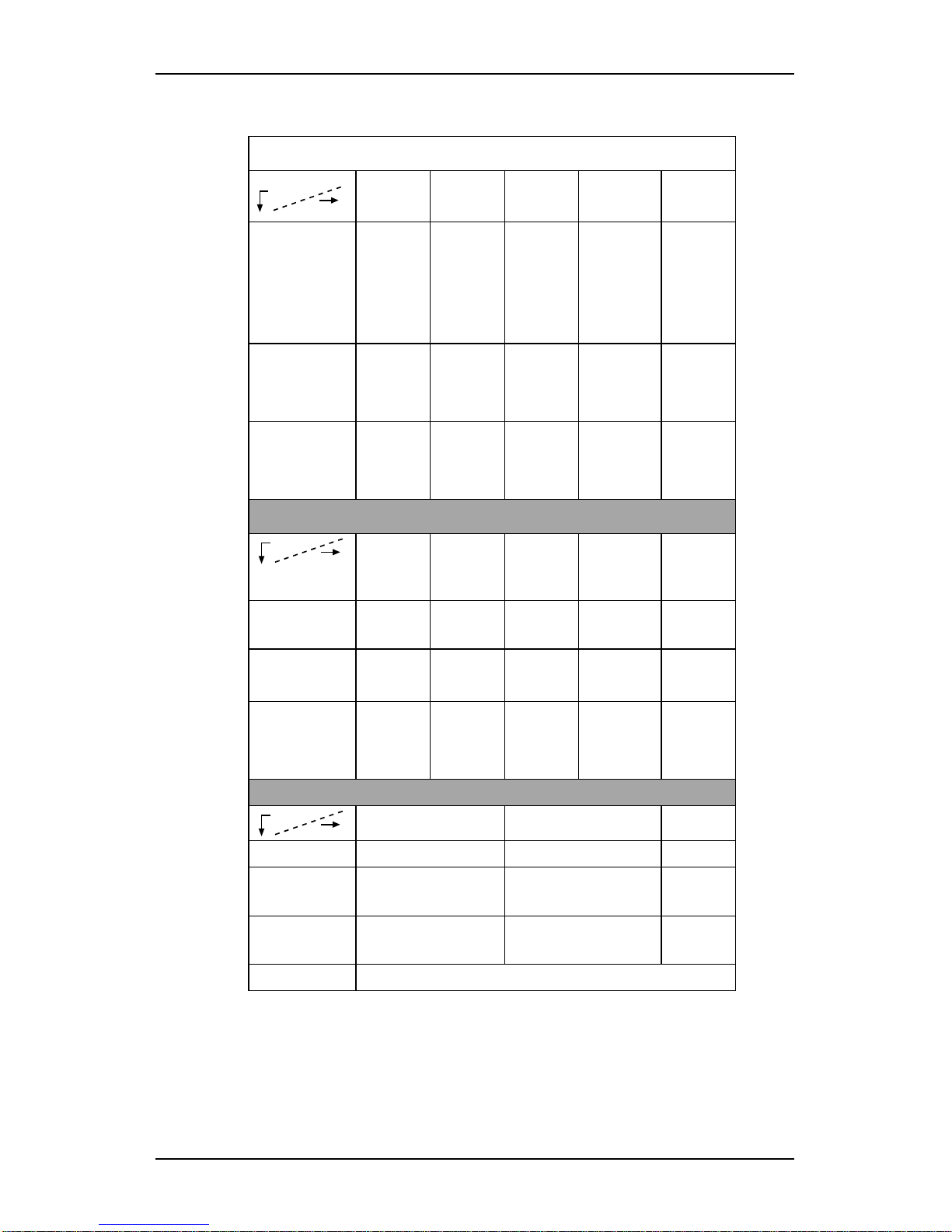
MultiVOIP Product Family
Model
Description
MVP-
2410
MVP
24-48
MVP
3010
MVP
30-60
Function T1
digital
VOIP
unit
T1
digital
VOIP
add-on
card
E1
digital
VOIP
unit
E1
digital
VOIP
add-on
card
Capacity 24
channels
24
added
channels
30
channels
30
added
channels
Chassis
/
Mounting
19” 1U
rack
mount
circuit
card
only
19” 1U
rack
mount
circuit
card
only
Model
Description
MVP
810
MVP
428
MVP
410
MVP
210
MVP130/
130FXS
Function analog
voip
add-on
card
analog
voip
analog
voip
analog
voip
Capacity 8
channels
4 added
channels
4
channels
2
channels
1
channel
Chassis
/
Mounting
19” 1U
rack
mount
circuit
card
only
19” 1U
rack
mount
Table
top
table
top
Model
Description
MVP810ST MVP410ST
Function ISDN-BRI voip ISDN-BRI voip
Capacity 4 ISDN lines
(8 B-channels)
2 ISDN lines
(4 B-channels)
Chassis
/
Mounting
19” 1U rack mount 19” 1U rack mount
1. “BRI” means Basic Rate Interface.
Page 10

Overview MultiVOIP User Guide
10
How to Use This Manual. In short, use the index and the examples.
When our readers crack open this large manual, they generally need
one of two things: information on a very specific software setting or
technical parameter (about telephony or IP) or they need help when
setting up phonebooks for their voip systems. The index gives quick
access to voip settings and parameters. It’s detailed. Use it. The best
way to learn about phonebooks is to wade through examples like those
in our chapters on T1 (North American standard) Phonebooks and E1
(Euro standard) Phonebooks. Also, the quick setup info of the printed
Quick Start Guide is replicated in this manual for your convenience.
Finally, this manual is meant to be comprehensive. If you notice that
something important is lacking, please let us know.
Additional Resources. The MultiTech web site (www.multitech.com)
offers both a list of Frequently Asked Questions (the MultiVOIP FAQ)
and a collection of resolutions of issues that MultiVOIP users have
encountered (these are Troubleshooting Resolutions in the searchable
Knowledge Base).
Variable Model/Version Icon and Typography. The MultiVOIP
product family is a coordinated set of products that can operate with
each other in a seamless fashion. For example, both the digital and
analog MultiVOIP units use the same graphic user interface (GUI) in
the MultiVOIP configuration software and both operate under a single
GUI in the MultiVoipManager remote management software. Because
this is the case, the various model numbers and version numbers of
MultiVOIP family products will each appear in various dialog boxes
and commands. But instead of showing these dialog boxes once for
each model in this manual, we substitute the following icon.
Figure 1-1: Variable Model/Version Icon
It indicates that, whatever MultiVOIP model you are using, all details
except the very model and version numbers themselves will be the
same regardless of the MultiVOIP model used. Also, in some cases, we
will use other typographic devices, like blank underlining
(“MultiVOIP ____”) to denote information that applies to any
and all of the products in this product family.
Page 11
MultiVOIP User Guide Overview
11
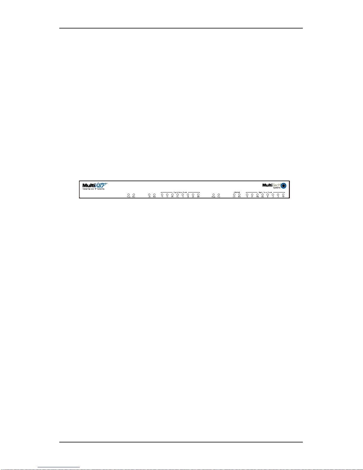
Introduction to TI MultiVOIPs (MVP2410 &
MVP24-48)
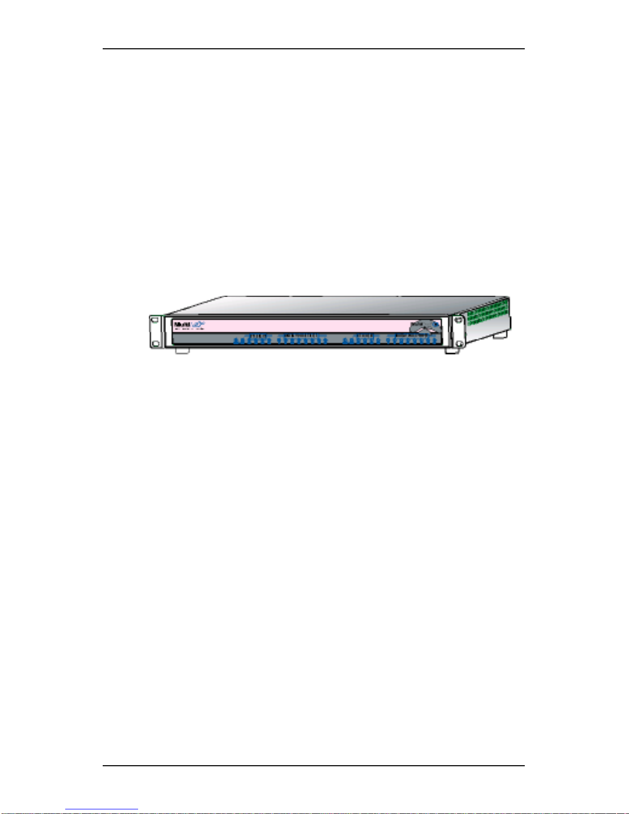
We proudly present MultiTech’s T1 Digital Multi-VOIP products.
The MVP2410 is a rack-mount model; and the MVP24-48 is an add-on
expansion card that doubles the capacity of the MVP2410 without
adding another chassis. These voice-over-IP products have fax
capabilities. These models adhere to the North American standard of
T1 trunk telephony using digital 24-channel time-division multiplexing,
which allows 24 phone conversations to occur on the T1 line
simultaneously. They can also accommodate T1 lines of the ISDN
Primary Rate Interface type (ISDN-PRI).
Figure 1-2. MultiVOIP MVP2410 LEDs
Scale-ability. The MVP2410 is tailored to companies needing more
than a few voice-over-IP lines, but not needing carrier-class equipment.
When expansion is needed, the MVP2410 can be field-upgraded into a
dual T1 unit by installing the MVP24-48 kit, which is essentially a
second MultiVOIP motherboard that fits in an open expansion-card slot
in the MVP2410. The upgraded dual unit then accommodates two T1
lines.
T1 VOIP Traffic. The MVP2410 accepts its outbound traffic from a T1
trunk that’s connected to either a PBX or to a telco/carrier. The
MVP2410 transforms the telephony signals into IP packets for
transmission on LANs, WANs, or the Internet. Inbound IP data traffic
is converted to telephony data and signaling.
When connected to PBX. When connected to a PBX, the MVP2410
creates a network node served by 10/100-Base T connections. Local
PBX phone extensions gain toll-free access to all phone stations directly
connected to the VOIP network. Phone extensions at any VOIP location
also gain toll-free access to the entire local public-switched telephone
network (PSTN) at every other VOIP location in the system.
When connected to PSTN. When the T1 line(s) connected to the
MVP2410 are connected directly to the PSTN, the unit becomes a Pointof-Presence server dedicated to local calls off-net.
Page 12

Overview MultiVOIP User Guide
12
H.323, SIP & SPP. Being H.323 compatible, the MVP2410 can place
calls to telephone equipment at remote IP network locations that also
contain H.323 compatible voice-over-IP gateways. It will interface with
H.323 software and H.323 gatekeeper units. H.323 specifications also
bring to voip telephony many special features common to conventional
telephony. H.323 features of this kind that have been implemented into
the MultiVOIP include Call Hold, Call Waiting, Call Name
Identification, Call Forwarding (from the H.450 standard), and Call
Transfer (H.450.2 from H.323 Version 2). The fourth version of the
H.323 standard improves system resource usage (esp. logical port or
socket usage) by handling call signaling more compactly and allowing
use of the low-overhead UDP protocol instead of the error-correcting
TCP protocol where possible.
The MultiVOIP is also SIP-compatible. (“SIP” means Session Initiation
Protocol.) However, H.450 Supplementary Services features can be
used under H.323 only and not under SIP.
SPP (Single-Port Protocol) is a non-standard protocol developed by
Multi-Tech. SPP is not compatible with the “Proprietary” protocol used
in Multi-Tech’s earlier generation of voip gateways. SPP offers
advantages in certain situations, especially when firewalls are used and
when dynamic IP address assignment is needed. However, when SPP
is used, certain features of SIP and H.323 will not be available and SPP
will not inter-operate with voip systems using H.323 or SIP.
Data Compression & Quality of Service. The MultiVOIP MVP2410
comes equipped with a variety of data compression capabilities,
including G.723, G.729, and G.711 and features DiffServ quality-ofservice (QoS) capabilities.
VOIP Functions. The MultiVOIP MVP2410 gateway performs four
basic functions: (a) it converts a dialed number into an IP address, (b) it
sends voice over the data network, (c) it establishes a connection with
another VOIP gateway at a remote site, and (d) it receives voice over
the data network. Voice is handled as IP packets with a variety of
compression options. Each T1 connection to the MultiVOIP provides 24
time-slot channels to connect to the telco or to serve phone or fax
stations connected to a PBX.
Ports. The MVP2410 has one 10/100 Mbps Ethernet LAN interface and
one Command port for configuration. An MVP2410 upgraded with the
MVP24-48 kit will have two Ethernet LAN interfaces and two
Command ports.
PSTN Failover Feature. The MultiVOIP can be programmed to divert
calls to the PSTN temporarily in case the IP network fails.
Gatekeeper. T1 voip systems can have gatekeeper functionality by
adding, as an endpoint, a Multi-Tech standalone gatekeeper (special
Page 13

MultiVOIP User Guide Overview
13
software residing in separate hardware). Gatekeepers are optional but
useful within voip systems. The gatekeeper acts as the ‘clearinghouse’
for all calls within its zone. MultiTech’s stand-alone gatekeeper
software performs all of the standard gatekeepers functions (address
translation, admission control, and bandwidth control) and also
supports many valuable optional functions (call control signaling, call
authorization, bandwidth management, and call management).
Management. Configuration and system management can be done
locally with the MultiVOIP configuration software. After an IP address
has been assigned locally, other configuration can be done remotely
using the MultiVOIP web browser GUI. Remote system management
can be done with the MultiVoipManager SNMP software or via the
MultiVOIP web browser GUI. All of these control software packages
are included on the Product CD.
Page 14
Overview MultiVOIP User Guide
14
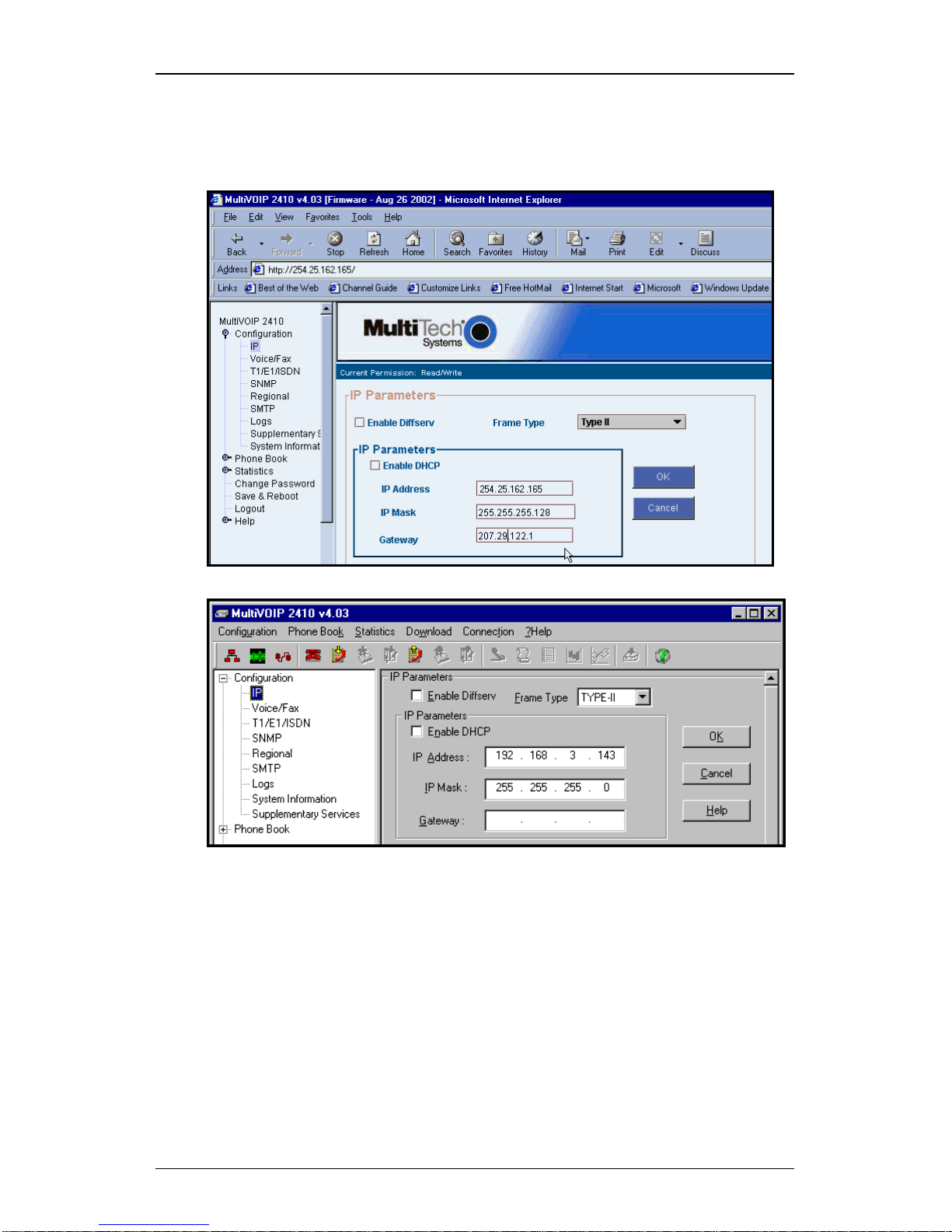
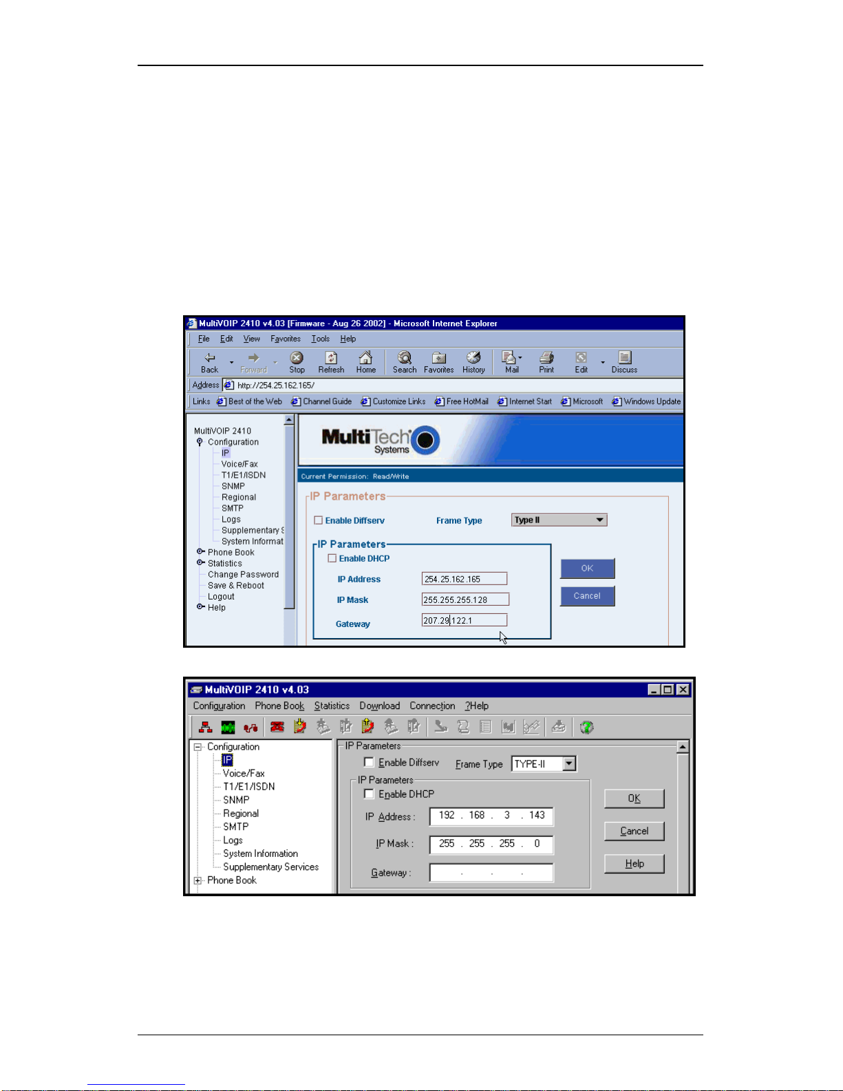
While the web GUI’s appearance differs slightly, its content and
organization are essentially the same as that of the Windows GUI
(except for logging).
The primary advantage of the web GUI is remote access for control and
configuration. The controller PC and the MultiVOIP unit itself must
both be connected to the same IP network and their IP addresses must
be known.
Once you’ve begun using the web browser GUI, you can go back to the
MultiVOIP Windows GUI at any time. However, you must log out of
the web browser GUI before using the MultiVOIP Windows GUI.
Page 15

MultiVOIP User Guide Overview
15
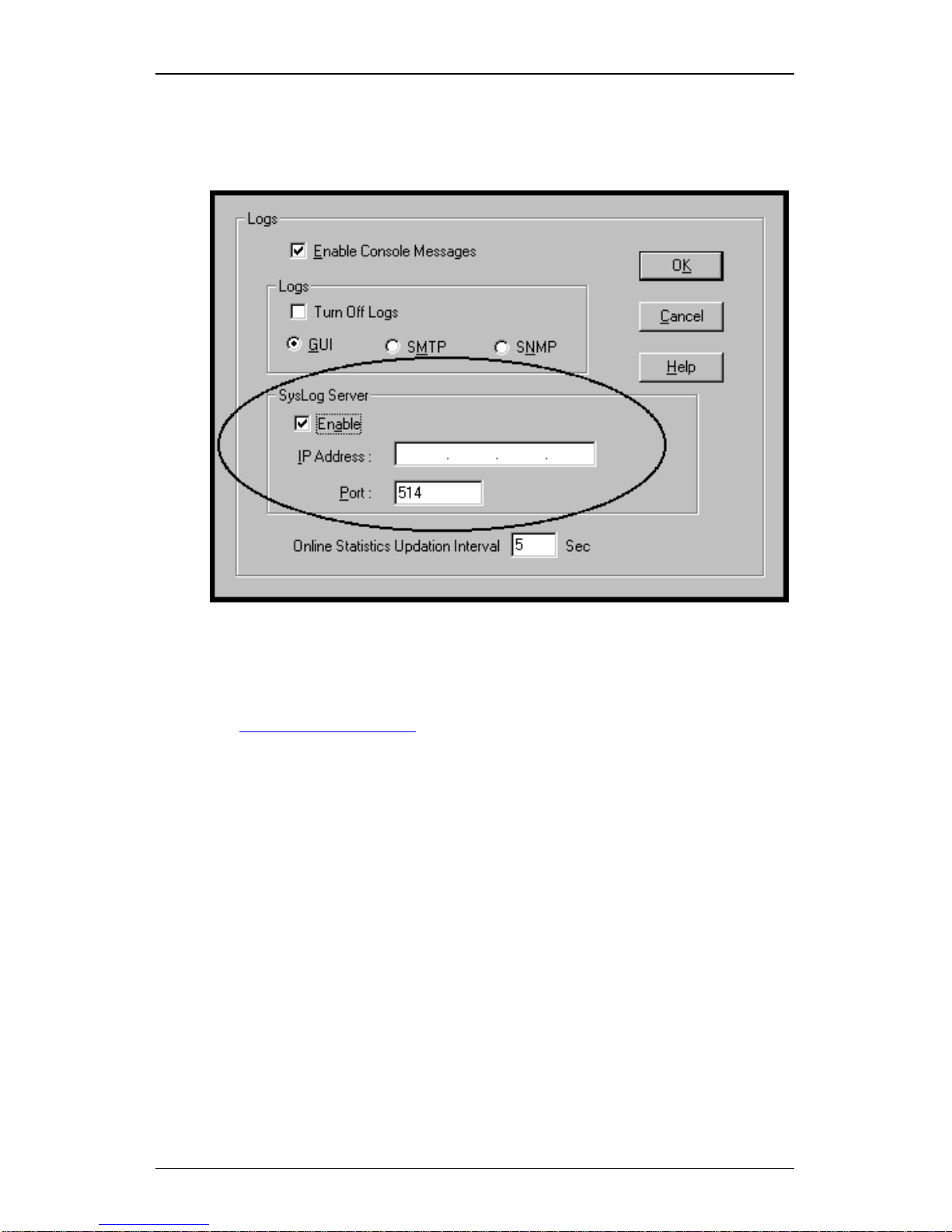
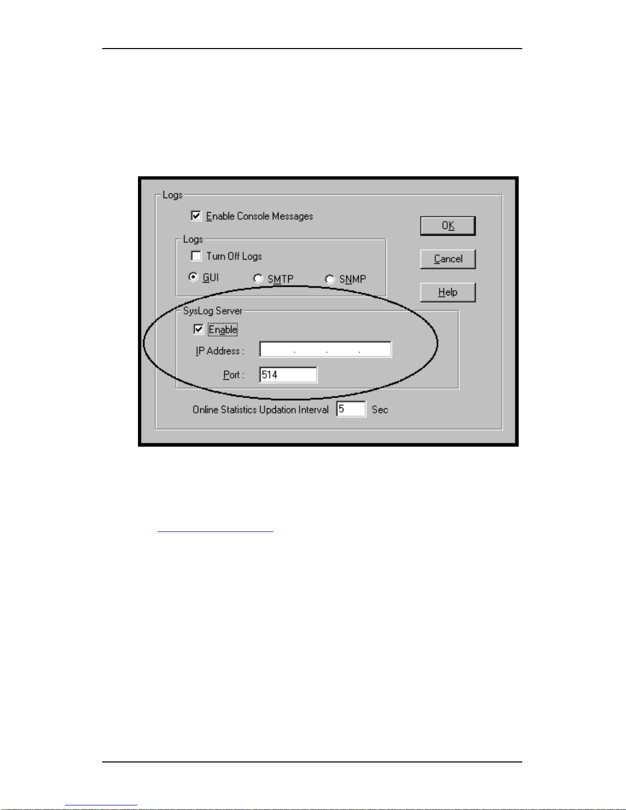
Logging of System Events. MultiTech has built SysLog Server
functionality into the software of the MultiVOIP units. SysLog is a de
facto standard for logging events in network communication systems.
The SysLog Server resides in the MultiVOIP unit itself. To implement
this functionality, you will need a SysLog client program (sometimes
referred to as a “daemon”). SysLog client programs, both paid and
freeware, can be obtained from Kiwi Enterprises, among other firms.
See www.kiwisyslog.com
. SysLog client programs essentially give you
a means of structuring console messages for convenience and ease of
use.
MultiTech Systems does not endorse any particular SysLog client
program. SysLog client programs by any qualified provider should
suffice for use with MultiVOIP units. Kiwi’s brief description of their
SysLog program indicates the typical scope of such programs. “Kiwi
Syslog Daemon is a freeware Syslog Daemon for the Windows
platform. It receives, logs, displays and forwards Syslog messages from
hosts such as routers, switches, Unix hosts and any other syslog
enabled device. There are many customizable options available.”
Page 16
Overview MultiVOIP User Guide
16
Supplementary Telephony Services. The H.450 standard (an addition
to H.323) brings to voip telephony more of the premium features found
in PSTN and PBX telephony. MultiVOIP units offer five of these H.450
features: Call Transfer, Call Hold, Call Waiting, Call Name
Identification (not the same as Caller ID), and Call Forwarding. (The
first four features are found in the “Supplementary Services” window;
the fifth, Call Forwarding, appears in the Add/Edit Inbound
phonebook screen.) Note that the first three features are closely related.
All of these H.450 features are supported for H.323 operation only; they
are not supported for SIP or SPP.
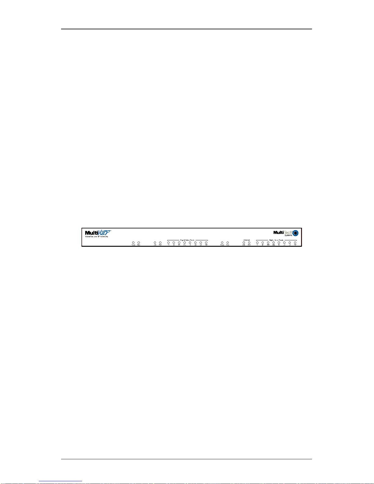
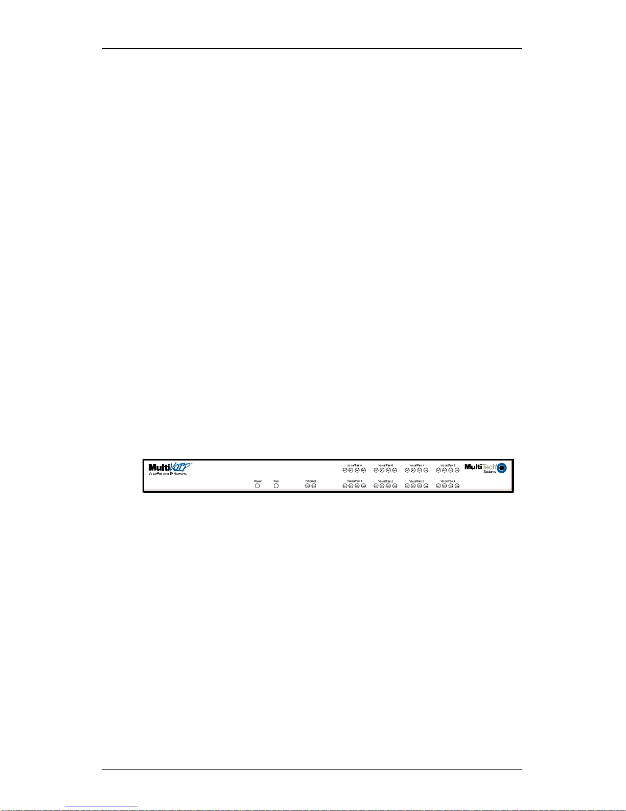
T1 Front Panel LEDs
The MVP2410 and MVP24-48 both use a common main circuit board or
motherboard. Consequently the LED indicators are the same for both.
Active LEDs. The MVP2410 front panel has two sets of identical LEDs.
In the MVP2410 as shipped (that is, without an expansion card), the
left-hand set of LEDs is functional whereas the right-hand set is not.
When the MVP2410 has been upgraded with an MVP24-48 kit, the
right-hand set of LEDs will also become active.
Figure 1-3: MVP2410 LEDs
T1 LED Descriptions. The descriptions below apply to the digital T1
MultiVOIP units. The MVP2410 has four sets of LEDs plus a lone LED
at its far right end. As viewed from the front of the MVP2410, it is the
two left groups that are active and present feedback about the operation
of the unit. If an MVP24-48 expansion card is added to the MVP2410,
the two LED groups on the right become operational with respect to the
second T1 connection.
Page 17

MultiVOIP User Guide Overview
17
MVP2410 Front Panel LED Definitions
LED NAME DESCRIPTION
Power Indicates presence of power.
Boot
After power up, the Boot LED will be on for about 10
seconds while the MVP2410 is booting.
FDX Full-Duplex & Collision LED. This LED indicates
whether the Ethernet connection is half-duplex or fullduplex (FDX) and, in half-duplex mode, indicates
occurrence of data collisions. LED is on constantly for
full-duplex mode; LED is off constantly for half-duplex
mode. When operating in half-duplex mode, the LED
will flash during data collisions.
LNK Link/Activity LED. This LED is lit if Ethernet
connection has been made. It is off when the link is
down (i.e., when no Ethernet connection exists). While
link is up, this LED will flash off to indicate data
activity.
T1 When lit, indicates presence of T1 connection.
E1 E1. Not supported.
PRI PRI. On if T1 line is of ISDN-Primary-Rate type.
ONL Online. This LED is on when frame synchroni-
zation has been established on the T1/E1 link.
IC IC LED is on when Internal Clocking is selected in
T1/E1 configuration.
LC Indicates Loss of Carrier.
LS Indicates Loss of Signal.
Test For testing purposes only.
Page 18

Overview MultiVOIP User Guide
18
Introduction to EI MultiVOIPs
(MVP3010 & MVP30-60)
We proudly present MultiTech’s E1 Digital Multi-VOIP products. The
MVP3010 is a rack-mount model and the MVP30-60 is an add-on
expansion card that doubles the capacity of the MVP3010 without
adding another chassis. All of these voice-over-IP products have fax
capabilities. All adhere to the European standard of E1 trunk telephony
using digital 30-channel time-division multiplexing, which allows 30
phone conversations to occur on the E1 line simultaneously. All can
also accommodate E1 lines of the ISDN Primary Rate Interface type
(ISDN-PRI).
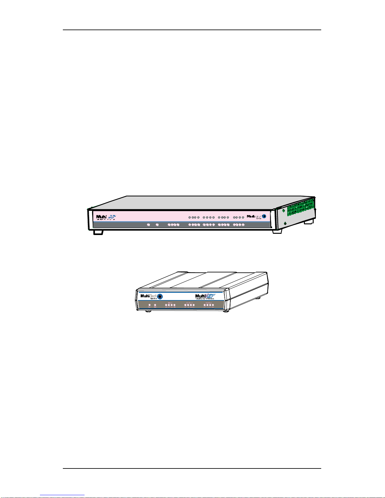
Figure 1-4. MultiVOIP MVP3010 Chassis
Scale-ability. The MVP3010 is tailored to companies needing more
than a few voice-over-IP lines, but not needing carrier-class equipment.
When expansion is needed, the MVP3010 can be field-upgraded into a
dual E1 unit by installing the MVP30-60 kit, which is essentially a
second MultiVOIP motherboard that fits into an open expansion-card
slot in the MVP3010. The upgraded dual unit then accommodates two
E1 lines.
E1 VOIP Traffic. The MVP3010 accepts its outbound traffic from an E1
trunk that’s connected to either a PBX or to a telco/carrier. The
MVP3010 transforms the telephony signals into IP packets for
transmission on LANs, WANs, or the Internet. Inbound IP data traffic
is converted to telephony data and signaling.
When connected to PBX. When connected to a PBX, the MVP3010
creates a network node served by 10/100-Base T connections. Local
PBX phone extensions gain toll-free access to all phone stations directly
connected to the VOIP network. Phone extensions at any VOIP location
also gain local-rate access to the entire local public-switched telephone
network (PSTN) at every other VOIP location in the system.
When connected to PSTN. When the E1 line(s) connected to the
MVP3010 are connected directly to the PSTN, the unit becomes a Pointof-Presence server dedicated to local calls off-net.
Page 19

MultiVOIP User Guide Overview
19
H. 323, SIP, & SPP. Being H.323 compatible, the MVP3010 can place
calls to telephone equipment at remote IP network locations that also
contain H.323 compatible voice-over-IP gateways. It will interface with
H.323 software and H.323 gatekeeper units. H.323 specifications also
bring to voip telephony many special features common to conventional
telephony. H.323 features of this kind that have been implemented into
the MultiVOIP include Call Hold, Call Waiting, Call Identification, Call
Forwarding (from the H.450 standard), and Call Transfer (H.450.2 from
H.323 Version 2). The fourth version of the H.323 standard improves
system resource usage (esp. logical port or socket usage) by handling
call signaling more compactly and allowing use of the low-overhead
UDP protocol instead of the error-correcting TCP protocol where
possible.
The MultiVOIP is also SIP-compatible. (“SIP” means Session Initiation
Protocol.) However, H.450 Supplementary Services features can be
used under H.323 only and not under SIP.
SPP (Single-Port Protocol) is a non-standard protocol developed by
Multi-Tech. SPP is not compatible with the “Proprietary” protocol used
in Multi-Tech’s earlier generation of voip gateways. SPP offers
advantages in certain situations, especially when firewalls are used and
when dynamic IP address assignment is needed. However, when SPP
is used, certain features of SIP and H.323 will not be available and SPP
will not inter-operate with voip systems using H.323 or SIP.
Data Compression & Quality of Service. The MultiVOIP3010 comes
equipped with a variety of data compression capabilities, including
G.723, G.729, and G.711 and features DiffServ quality-of-service (QoS)
capabilities.
VOIP Functions. The MultiVOIP MVP3010 gateway performs four
basic functions: (a) it converts a dialed number into an IP address, (b) it
sends voice over the data network, (c) it establishes a connection with
another VOIP gateway at a remote site, and (d) it receives voice over
the data network. Voice is handled as IP packets with a variety of
compression options. Each E1 connection to the MultiVOIP provides 30
time-slot channels to connect to the telco or to serve phone or fax
stations connected to a PBX.
Ports. The MVP3010 also has a 10/100 Mbps Ethernet LAN interface,
and a Command port for configuration. An MVP3010 upgraded with
the MVP30-60 kit will have two Ethernet LAN interfaces and two
Command ports.
PSTN Failover Feature. The MultiVOIP can be programmed to divert
calls to the PSTN temporarily in case the IP network fails.
Page 20

Overview MultiVOIP User Guide
20
Gatekeeper. E1 voip systems can have gatekeeper functionality by
adding, as an endpoint, a Multi-Tech standalone gatekeeper (special
software residing in separate hardware). Gatekeepers are optional but
useful within voip systems. The gatekeeper acts as the ‘clearinghouse’
for all calls within its zone. MultiTech’s stand-alone gatekeeper
software performs all of the standard gatekeepers functions (address
translation, admission control, bandwidth control, and zone
management) and also supports many valuable optional functions (call
control signaling, call authorization, and bandwidth management).
Management. Configuration and system management can be done
locally with the MultiVOIP configuration software. After an IP address
has been assigned locally, other configuration can be done remotely
using the MultiVOIP web browser GUI. Remote system management
can be done with the MultiVoipManager SNMP software or via the
MultiVOIP web browser GUI. All of these control software packages
are included on the Product CD.
Page 21

MultiVOIP User Guide Overview
21
While the web GUI’s appearance differs slightly, its content and
organization are essentially the same as that of the Windows GUI
(except for logging).
The primary advantage of the web GUI is remote access for control and
configuration. The controller PC and the MultiVOIP unit itself must
both be connected to the same IP network and their IP addresses must
be known.
Once you’ve begun using the web browser GUI, you can go back to the
MultiVOIP Windows GUI at any time. However, you must log out of
the web browser GUI before using the MultiVOIP Windows GUI.
Page 22
Overview MultiVOIP User Guide
22
Logging of System Events. MultiTech has built SysLog Server
functionality into the software of the MultiVOIP units. SysLog is a de
facto standard for logging events in network communication systems.
The SysLog Server resides in the MultiVOIP unit itself. To implement
this functionality, you will need a SysLog client program (sometimes
referred to as a “daemon”). SysLog client programs, both paid and
freeware, can be obtained from Kiwi Enterprises, among other firms.
See www.kiwisyslog.com
. SysLog client programs essentially give you
a means of structuring console messages for convenience and ease of
use.
MultiTech Systems does not endorse any particular SysLog client
program. SysLog client programs by any qualified provider should
suffice for use with MultiVOIP units. Kiwi’s brief description of their
SysLog program indicates the typical scope of such programs. “Kiwi
Syslog Daemon is a freeware Syslog Daemon for the Windows
platform. It receives, logs, displays and forwards Syslog messages from
hosts such as routers, switches, Unix hosts and any other syslog
enabled device. There are many customizable options available.”
Page 23
MultiVOIP User Guide Overview
23
Supplementary Telephony Services. The H.450 standard (an addition
to H.323) brings to voip telephony more of the premium features found
in PSTN and PBX telephony. MultiVOIP units offer five of these H.450
features: Call Transfer, Call Hold, Call Waiting, Call Name
Identification (not the same as Caller ID), and Call Forwarding. (The
first four features are found in the “Supplementary Services” window;
the fifth, Call Forwarding, appears in the Add/Edit Inbound
phonebook screen.) Note that the first three features are closely related.
All of these H.450 features are supported for H.323 operation only; they
are not supported for SIP or SPP.
E1 Front Panel LEDs
Because the MVP3010 and MVP30-60 both use a common main circuit
card or motherboard, the LED indicators are the same for both.
Figure 1-5: MVP3010 LEDs
Active LEDs. The MVP3010 front panel has two sets of identical LEDs.
In the MVP3010 as shipped (that is, without an expansion card), the
left-hand set of LEDs is functional whereas the right-hand set is not.
When the MVP3010 has been upgraded with an MVP30-60 kit, the
right-hand set of LEDs will also become active.
Page 24

Overview MultiVOIP User Guide
24
E1 LED Descriptions
MVP3010 Front Panel LED Definitions
LED NAME DESCRIPTION
Power Indicates presence of power.
Boot
After power up, the Boot LED will be on for
about 10 seconds while the MVP3010 is booting.
FDX Full-Duplex & Collision LED. This LED indicates
whether the Ethernet connection is half-duplex or fullduplex (FDX) and, in half-duplex mode, indicates
occurrence of data collisions. LED is on constantly for
full-duplex mode; LED is off constantly for halfduplex mode. When operating in half-duplex mode,
the LED will flash during data collisions.
LNK Link/Activity LED. This LED is lit if Ethernet
connection has been made. It is off when the link is
down (i.e., when no Ethernet connection exists).
While link is up, this LED will flash off to indicate data
activity.
T1 T1. Not supported.
E1 E1. When lit, indicates presence of E1
connection.
PRI PRI. On if E1 line is of ISDN-Primary-Rate type.
ONL Online. This LED is on when frame
synchronization has been established on the
T1/E1 link.
IC IC LED is on when Internal Clocking is selected
in T1/E1 configuration.
LC Indicates Loss of Carrier.
LS Indicates Loss of Signal.
Test For testing purposes only.
Page 25
MultiVOIP User Guide Overview
25
Introduction to Analog MultiVOIPs
(MVP-130/130FXS, MVP-210/410/810 &
MVP428)
VOIP: The Free Ride. We proudly present Multi-Tech's MVP130/130FXS and MVP-210/410/810 generation of MultiVOIP Voiceover-IP Gateways. All of these models allow voice/fax communication
to be transmitted at no additional expense over your existing IP
network, which has ordinarily been data only. To access this free voice
and fax communication, you simply connect the MultiVOIP to your
telephone equipment and your existing Internet connection. These
analog MultiVOIPs inter-operate readily with T1 or E1 MultiVOIP
units.
RCV X MT COLLNK XMTRCV XSG RSG
XMT RCVXSG RSG XMTRCV XSG RSGXMT RCV XSGRSG
XMT RCV XSGRSG
XMTRCV XSG RSG
XMTRCV XSG RSG
Voice/Fax 5Voice/Fax 6Voice/Fax 7Voice/Fax 8
Voice /Fax 1Voice/Fax 2Voice/Fax 3 Voi ce/ Fax 4EthernetBoot
Power
XMT RCVXSG RSG
Figure 1-6: MVP-410/810 Chassis
Figure 1-7: MVP-210 Chassis
Page 26
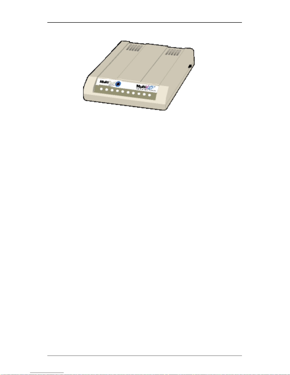
Overview MultiVOIP User Guide
26
Figure 1-8: MultiVOIP MVP-130/130FXS Chassis
Capacity. MultiVOIP model MVP810 is an eight-channel unit, the
model MVP410 is a four-channel, the model MVP210 is a two-channel
units, the MV130 is a single-channel unit and the MVP130FXS is a
single-channel unit that supports the FXS telephony interface only. All
of these MultiVOIP units have a 10/100Mbps Ethernet interface and a
command port for configuration. The MVP428 is an expansion circuit
card for the four-channel MVP410 that turns it into an eight-channel
voip.
Mounting. Mechanically, the MVP410 and MVP810 MultiVOIPs are
designed for a one-high industry-standard EIA 19-inch rack enclosure.
By contrast, MVP-130/130FXS and the MVP210 are tabletop units. The
product must be installed by qualified service personnel in a restrictedaccess area, in accordance with Articles 110-16, 10-17, and 110-18 of the
National Electrical Code, ANSI/NFPA 70.
Phone System Transparency. These MultiVOIPs inter-operate with a
telephone switch or PBX, acting as a switching device that directs voice
and fax calls over an IP network. The MultiVOIPs have “phonebooks,”
directories that determine to who calls may be made and the sequences
that must be used to complete calls through the MultiVOIP. The
phonebooks allow the phone user to interact with the VOIP system just
as they would with an ordinary PBX or telco switch. When the
phonebooks are set, special dialing sequences are minimized or
eliminated altogether. Once the call destination is determined, the
phonebook settings determine whether the destination VOIP unit must
strip off or add dialing digits to make the call appear at its destination
to be a local call.
Page 27

MultiVOIP User Guide Overview
27
H. 323, SIP, & SPP. Being H.323 compatible, the analog MultiVOIP
unit can place calls to telephone equipment at remote IP network
locations that also contain H.323 compatible voice-over-IP gateways. It
will interface with H.323 software and H.323 gatekeeper units. H.323
specifications also bring to voip telephony many special features
common to conventional telephony. H.323 features of this kind that
have been implemented into the MultiVOIP include Call Hold, Call
Waiting, Call Identification, Call Forwarding (from the H.450 standard),
and Call Transfer (H.450.2 from H.323 Version 2). The fourth version of
the H.323 standard improves system resource usage (esp. logical port or
socket usage) by handling call signaling more compactly and allowing
use of the low-overhead UDP protocol instead of the error-correcting
TCP protocol where possible.
The MultiVOIP is also SIP-compatible. (“SIP” means Session Initiation
Protocol.) However, H.450 Supplementary Services features can be
used under H.323 only and not under SIP.
SPP (Single-Port Protocol) is a non-standard protocol developed by
Multi-Tech. SPP is not compatible with the “Proprietary” protocol used
in Multi-Tech’s earlier generation of voip gateways. SPP offers
advantages in certain situations, especially when firewalls are used and
when dynamic IP address assignment is needed. However, when SPP
is used, certain features of SIP and H.323 will not be available and SPP
will not inter-operate with voip systems using H.323 or SIP.
Data Compression & Quality of Service. The analog MultiVOIP unit
comes equipped with a variety of data compression capabilities,
including G.723, G.729, and G.711 and features DiffServ quality-ofservice (QoS) capabilities.
PSTN Failover Feature. The MultiVOIP can be programmed to divert
calls to the PSTN temporarily in case the IP network fails.
Gatekeepers. For voip systems built with MultiTech’s analog gateway
units, users can have a stand-alone gatekeeper (gatekeeper software
residing in separate hardware). Gatekeepers are optional but useful
within voip systems. The gatekeeper acts as the ‘clearinghouse’ for all
calls within its zone. MultiTech’s stand-alone gatekeeper software
performs all of the standard gatekeepers functions (address translation,
admission control, and bandwidth control) and also supports many
valuable optional functions (call control signaling, call authorization,
bandwidth management, and call management).
Page 28
Overview MultiVOIP User Guide
28
Management. Configuration and system management can be done
locally with the MultiVOIP configuration software. After an IP address
has been assigned locally, other configuration can be done remotely
using the MultiVOIP web browser GUI. Remote system management
can be done with the MultiVoipManager SNMP software or via the
MultiVOIP web browser GUI. All of these control software packages
are included on the Product CD.
While the web GUI’s appearance differs slightly, its content and
organization are essentially the same as that of the Windows GUI
(except for logging).
The primary advantage of the web GUI is remote access for control and
configuration. The controller PC and the MultiVOIP unit itself must
both be connected to the same IP network and their IP addresses must
be known.
Page 29
MultiVOIP User Guide Overview
29
Once you’ve begun using the web browser GUI, you can go back to the
MultiVOIP Windows GUI at any time. However, you must log out of
the web browser GUI before using the MultiVOIP Windows GUI.
Logging of System Events. MultiTech has built SysLog Server
functionality into the software of the MultiVOIP units. SysLog is a de
facto standard for logging events in network communication systems.
The SysLog Server resides in the MultiVOIP unit itself. To implement
this functionality, you will need a SysLog client program (sometimes
referred to as a “daemon”). SysLog client programs, both paid and
freeware, can be obtained from Kiwi Enterprises, among other firms.
See www.kiwisyslog.com
. SysLog client programs essentially give you
a means of structuring console messages for convenience and ease of
use.
MultiTech Systems does not endorse any particular SysLog client
program. SysLog client programs by any qualified provider should
suffice for use with MultiVOIP units. Kiwi’s brief description of their
SysLog program indicates the typical scope of such programs. “Kiwi
Syslog Daemon is a freeware Syslog Daemon for the Windows
platform. It receives, logs, displays and forwards Syslog messages from
hosts such as routers, switches, Unix hosts and any other syslog
enabled device. There are many customizable options available.”
Page 30
Overview MultiVOIP User Guide
30
Supplementary Telephony Services. The H.450 standard (an addition
to H.323) brings to voip telephony more of the premium features found
in PSTN and PBX telephony. MultiVOIP units offer five of these H.450
features: Call Transfer, Call Hold, Call Waiting, Call Name
Identification (not the same as Caller ID), and Call Forwarding. (The
first four features are found in the “Supplementary Services” window;
the fifth, Call Forwarding, appears in the Add/Edit Inbound
phonebook screen.) Note that the first three features are closely related.
All of these H.450 features are supported for H.323 operation only; they
are not supported for SIP or SPP.
Analog MultiVOIP Front Panel LEDs
LED Types. The MultiVOIPs have two types of LEDs on their front
panels:
(1) general operation LED indicators (for power, booting, and
ethernet functions), and
(2) channel operation LED indicators that describe the data traffic
and performance in each VOIP data channel.
Active LEDs. On both the MVP410 and MVP810, there are eight sets of
channel-operation LEDs. However, on the MVP410, only the lower
four sets of channel-operation LEDs are functional. On the MVP810, all
eight sets are functional.
Figure 1-9. MVP410/810 LEDs
Page 31

MultiVOIP User Guide Overview
31
Similarly, the MVP210 has the general-operation indicator LEDs and
two sets of channel-operation LEDs, one for each channel.
Figure 1-10. MVP210 LEDs
Finally, the MVP130 has the general-operation indicator LEDs and a set
of channel-operation LEDs for its single voip channel.
Figure 1-11. MVP-130/130FXS LEDs
Page 32

Overview MultiVOIP User Guide
32
Analog MultiVOIP LED Descriptions
MVP-210/410/810 Front Panel LED Definitions
LED NAME DESCRIPTION
General Operation LEDs (one set on each MultiVOIP model)
Power Indicates presence of power.
Boot
After power up, the Boot LED will be on briefly while the
MultiVOIP is booting. It lights whenever the MultiVOIP is
booting or downloading a setup configuration data set.
Ethernet
FDX. LED indicates whether Ethernet connection is
half-duplex or full-duplex (FDX) and, in half-duplex
mode, indicates occurrence of data collisions. LED is
on constantly for full-duplex mode; LED is off
constantly for half-duplex mode. When operating in
half-duplex mode, the LED will flash during data
collisions.
LNK. Link/Activity LED. This LED is lit if Ethernet
connection has been made. It is off when the link is
down (i.e., when no Ethernet connection exists).
While link is up, this LED will flash off to indicate data
activity.
Channel-Operation LEDs (one set for each channel)
XMT
Transmit. This indicator blinks when voice packets
are being transmitted to the local area network.
RCV
Receive. This indicator blinks when voice packets
are being received from the local area network.
XSG
Transmit Signal. This indicator lights when the FXS-
configured channel is off-hook, the FXO-configured
channel is receiving a ring from the Telco, or the M
lead is active on the E&M configured channel. That is,
it lights when the MultiVOIP is receiving a ring from
the PBX.
RSG
Receive Signal. This indicator lights when the FXS-
configured channel is ringing, the FXO-configured
channel has taken the line off-hook, or the E lead is
active on the E&M-configured channel.
Page 33

MultiVOIP User Guide Overview
33
MVP-130/130FXS Front Panel LED Definitions
LED NAME DESCRIPTION
General Operation LEDs
Power Indicates presence of power.
Boot
After power up, the Boot LED will be on briefly while
the MultiVOIP is booting. It lights whenever the
MultiVOIP is booting or downloading a setup
configuration data set.
Ethernet
FDX. LED indicates whether Ethernet connection is
half-duplex or full-duplex (FDX) and, in half-duplex
mode, indicates occurrence of data collisions. LED is
on constantly for full-duplex mode; LED is off
constantly for half-duplex mode. When operating in
half-duplex mode, the LED will flash during data
collisions.
LNK. Link/Activity LED. This LED is lit if Ethernet
connection has been made. It is off when the link is
down (i.e., when no Ethernet connection exists).
While link is up, this LED will flash off to indicate data
activity.
Channel-Operation LEDs
TX
Transmit. This indicator blinks when voice packets
are being transmitted to the local area network.
RX
Receive. This indicator blinks when voice packets
are being received from the local area network.
XS
Transmit Signal. This indicator lights when the
FXS-configured channel is off-hook or the FXOconfigured channel (MVP130 only) is receiving a ring
from the Telco or PBX.
RS
Receive Signal
. This indicator lights when the FXSconfigured channel is ringing or the FXO-configured
channel (MVP130 only) has taken the line off-hook.
Page 34

Overview MultiVOIP User Guide
34
Introduction to ISDN-BRI MultiVOIPs
(MVP410ST & MVP810ST)
VOIP: The Free Ride. We proudly present Multi-Tech's MVP410ST/810ST generation of MultiVOIP Voice-over-IP Gateways. All of
these models allow voice/fax communication to be transmitted at no
additional expense over your existing IP network, which has ordinarily
been data only. To access this free voice and fax communication, you
simply connect the MultiVOIP to your telephone equipment and your
existing Internet connection. These ISDN Basic Rate Interface (ISDNBRI) MultiVOIPs inter-operate readily with T1 or E1 MultiVOIP units
(T1 and E1 MultiVOIP units can operate in ISDN Primary Rate Mode,
ISDN-PRI, as well).
RCV XMT COL LNK
Ethernet
Boot
Power
ISDN 1
ISDN 2
ISDN 3
ISDN 4
D
XMT R CV XMT R CV
Ch 1 Ch 2
D
XMT R CV XMT R CV
Ch 3 Ch 4
D
XMT R CV XMT RCV
Ch 5 Ch 6
D
XMT R CV XMT RCV
Ch 7 Ch 8
Figure 1-12: MVP-410ST/810ST Chassis
Capacity. MultiVOIP model MVP810ST accommodates four ISDN-BRI
lines (eight B-channels) and model MVP410ST accommodates two
ISDN-BRI channels (four B-channels). Both of these MultiVOIP units
have a 10/100Mbps Ethernet interface and a command port for
configuration.
Mounting. Mechanically, the MVP410ST and MVP810ST MultiVOIPs
are designed for a one-high industry-standard EIA 19-inch rack
enclosure. The product must be installed by qualified service personnel
in a restricted-access area, in accordance with Articles 110-16, 10-17, and
110-18 of the National Electrical Code, ANSI/NFPA 70.
Phone System Transparency. These MultiVOIPs inter-operate with a
telephone switch or PBX, acting as a switching device that directs voice
and fax calls over an IP network. The MultiVOIPs have “phonebooks,”
directories that determine to who calls may be made and the sequences
that must be used to complete calls through the MultiVOIP. The
phonebooks allow the phone user to interact with the VOIP system just
as they would with an ordinary PBX or telco switch. When the
phonebooks are set, special dialing sequences are minimized or
eliminated altogether. Once the call destination is determined, the
phonebook settings determine whether the destination VOIP unit must
strip off or add dialing digits to make the call appear at its destination
to be a local call.
Page 35

MultiVOIP User Guide Overview
35
H. 323, SIP, & SPP. Being H.323 compatible, the BRI MultiVOIP unit
can place calls to telephone equipment at remote IP network locations
that also contain H.323 compatible voice-over-IP gateways. It will
interface with H.323 software and H.323 gatekeeper units. H.323
specifications also bring to voip telephony many special features
common to conventional telephony. H.323 features of this kind that
have been implemented into the MultiVOIP include Call Hold, Call
Waiting, Call Identification, Call Forwarding (from the H.450 standard),
and Call Transfer (H.450.2 from H.323 Version 2). The fourth version of
the H.323 standard improves system resource usage (esp. logical port or
socket usage) by handling call signaling more compactly and allowing
use of the low-overhead UDP protocol instead of the error-correcting
TCP protocol where possible.
The MultiVOIP is also SIP-compatible. (“SIP” means Session Initiation
Protocol.) However, H.450 Supplementary Services features can be
used under H.323 only and not under SIP.
SPP (Single-Port Protocol) is a non-standard protocol developed by
Multi-Tech. SPP is not compatible with the “Proprietary” protocol used
in Multi-Tech’s earlier generation of voip gateways. SPP offers
advantages in certain situations, especially when firewalls are used and
when dynamic IP address assignment is needed. However, when SPP
is used, certain features of SIP and H.323 will not be available and SPP
will not inter-operate with voip systems using H.323 or SIP.
Data Compression & Quality of Service. The BRI MultiVOIP unit
comes equipped with a variety of data compression capabilities,
including G.723, G.729, and G.711 and features DiffServ quality-ofservice (QoS) capabilities.
PSTN Failover Feature. The MultiVOIP can be programmed to divert
calls to the PSTN temporarily in case the IP network fails.
Gatekeeper. At this writing, ISDN-BRI MultiVOIP systems can have
gatekeeper functionality only by adding, as an endpoint, a standalone
gatekeeper (special software residing in separate hardware).
Gatekeepers are optional but useful within voip systems. The
gatekeeper acts as the ‘clearinghouse’ for all calls within its zone.
MultiTech’s embedded and stand-alone gatekeeper software packages
both perform all of the standard gatekeepers functions (address
translation, admission control, bandwidth control, and zone
management) and also support many valuable optional functions (call
control signaling, call authorization, bandwidth management, and call
management). The stand-alone gatekeeper is, however, slightly more
feature-rich than the embedded gatekeeper. For more details, see the
“Embedded Gatekeeper” chapter of this manual and the manual on
MultiTech’s stand-alone gatekeeper.
Page 36

Overview MultiVOIP User Guide
36
Management. Configuration and system management can be done
locally with the MultiVOIP configuration software. After an IP address
has been assigned locally, other configuration can be done remotely
using the MultiVOIP web browser GUI. Remote system management
can be done with the MultiVOIP web browser GUI. These control
software packages are included on the Product CD.
While the web GUI’s appearance differs slightly, its content and
organization are essentially the same as that of the Windows GUI
(except for logging).
The primary advantage of the web GUI is remote access for control and
configuration. The controller PC and the MultiVOIP unit itself must
both be connected to the same IP network and their IP addresses must
be known.
Page 37

MultiVOIP User Guide Overview
37
Once you’ve begun using the web browser GUI, you can go back to the
MultiVOIP Windows GUI at any time. However, you must log out of
the web browser GUI before using the MultiVOIP Windows GUI.
Logging of System Events. MultiTech has built SysLog Server
functionality into the software of the MultiVOIP units. SysLog is a de
facto standard for logging events in network communication systems.
The SysLog Server resides in the MultiVOIP unit itself. To implement
this functionality, you will need a SysLog client program (sometimes
referred to as a “daemon”). SysLog client programs, both paid and
freeware, can be obtained from Kiwi Enterprises, among other firms.
See www.kiwisyslog.com
. SysLog client programs essentially give you
a means of structuring console messages for convenience and ease of
use.
MultiTech Systems does not endorse any particular SysLog client
program. SysLog client programs by any qualified provider should
suffice for use with MultiVOIP units. Kiwi’s brief description of their
SysLog program indicates the typical scope of such programs. “Kiwi
Syslog Daemon is a freeware Syslog Daemon for the Windows
platform. It receives, logs, displays and forwards Syslog messages from
hosts such as routers, switches, Unix hosts and any other syslog
enabled device. There are many customizable options available.”
Page 38

Overview MultiVOIP User Guide
38
Supplementary Telephony Services. The H.450 standard (an addition
to H.323) brings to voip telephony more of the premium features found
in PSTN and PBX telephony. MultiVOIP units offer five of these H.450
features: Call Transfer, Call Hold, Call Waiting, Call Name
Identification (not the same as Caller ID), and Call Forwarding. (The
first four features are found in the “Supplementary Services” window;
the fifth, Call Forwarding, appears in the Add/Edit Inbound
phonebook screen.) Note that the first three features are closely related.
All of these H.450 features are supported for H.323 operation only; they
are not supported for SIP or SPP.
ISDN BRI MultiVOIP Fr ont Panel LEDs
LED Types. The MultiVOIPs have two types of LEDs on their front
panels:
(1) general operation LED indicators (for power, booting, and
ethernet functions), and
(2) channel operation LED indicators that describe the data traffic
and performance in each VOIP data channel.
Active LEDs. On the MVP810ST, there are four sets of ISDN-operation
LEDs. On the MVP410ST, there are two sets of ISDN-operation LEDs.
Each set contains one “D” LED and two sets of channel operation LEDs
(XMT and RCV).
Figure 1-13. MVP-410ST/810ST LEDs
Page 39

MultiVOIP User Guide Overview
39
ISDN-BRI MultiVOIP LED Descriptions
MVP-410ST/810ST Front Panel LED Definitions
LED NAME DESCRIPTION
General Operation LEDs (one set on each MultiVOIP model)
Power Indicates presence of power.
Boot
After power up, the Boot LED will be on briefly while the
MultiVOIP is booting. It lights whenever the MultiVOIP is
booting or downloading a setup configuration data set.
Ethernet
FDX. LED indicates whether Ethernet connection is
half-duplex or full-duplex (FDX) and, in half-duplex
mode, indicates occurrence of data collisions. LED is
on constantly for full-duplex mode; LED is off
constantly for half-duplex mode. When operating in
half-duplex mode, the LED will flash during data
collisions.
LNK. Link/Activity LED. This LED is lit if Ethernet
connection has been made. It is off when the link is
down (i.e., when no Ethernet connection exists).
While link is up, this LED will flash off to indicate data
activity.
D-Channel Operation LEDs (one for each ISDN line)
D
ISDN D-channel & physical layer indicator. One “D”
LED for each ISDN-BRI connection. The “D” LED is
off when the BRI physical layer is de-activated.* It
flashes when a connection is being established on the
physical layer. It is on when the physical layer has
been activated. It flickers to indicate D-channel traffic.
*If the voip is running in terminal mode and its BRI
line is unplugged, the D LED goes off. However, if the
voip is running in network mode and its BRI line is
unplugged, its LED will flash at regular interval.
B-Channel Operation LEDs (one for each B-channel)
XMT
Transmit. This indicator blinks when voice packets
are being transmitted onto the B-channel.
RCV
Receive. This indicator blinks when voice packets
are being received on the B-channel.
Page 40

Overview MultiVOIP User Guide
40
Computer Requirements
The computer on which the MultiVOIP’s configuration program is
installed must meet these requirements:
• must be IBM-compatible PC with MS Windows operating
system;
• must have an available COM port for connection to the
MultiVOIP.
However, this PC does not need to be connected to the MultiVOIP
permanently. It only needs to be connected when local configuration
and monitoring are done. Nearly all configuration and monitoring
functions can be done remotely via the IP network.
Page 41

MultiVOIP User Guide Overview
41
Specifications
Specs for Digital T1 MultiVOIP Units
Digital T1 MultiVOIP Specifications
Parameter
……/Model
MVP-2410
MVP-2410
w/ MVP24-48
Expansion
Card
Operating
Voltage/Current
100-240 VAC
1.2 - 0.6 A
100-240 VAC
1.2 - 0.6 A
Mains
Frequencies
50/60 Hz 50/60 Hz
Power
Consumption
17 watts 27 watts
Mechanical
Dimensions
1.75”H x
17.4”W x
8.75”D
4.5cm H x
44.2 cm W x
22.2 cm D
1.75”H x
17.4”W x
8.75”D
4.5cm H x
44.2 cm W x
22.2 cm D
Weight
7.1 lbs.
(3.2 kg)
7.5 lbs.
(3.4 kg)
Page 42

Overview MultiVOIP User Guide
42
Specs for Digital E1 MultiVOIP Units
Digital E1 MultiVOIP Specifications
Parameter
……/Model
MVP-3010 MVP-3010
w/ MVP30-60
Expansion
Card
Operating
Voltage/Current
100-240 VAC
1.2 - 0.6 A
100-240 VAC
1.2 - 0.6 A
Mains
Frequencies
50/60 Hz 50/60 Hz
Power
Consumption
17 watts 27 watts
Mechanical
Dimensions
1.75”H x
17.4”W x
8.75”D
4.5cm H x
44.2 cm W x
22.2 cm D
1.75”H x
17.4”W x
8.75”D
4.5cm H x
44.2 cm W x
22.2 cm D
Weight
7.1 lbs.
(3.2 kg)
7.5 lbs.
(3.4 kg)
Page 43

MultiVOIP User Guide Overview
43
Specs for Analog/BRI MultiVOIP Units
Parameter
/Model
MVP210 MVP410 MVP810 or
MVP410 + 428
Operating
Voltage/
Current
External
transformer:
3A @5V
100-240 VAC
1.2 - 0.6 A
100-240 VAC
1.2 - 0.6 A
Mains
Frequencies
50/60 Hz 50/60 Hz 50/60 Hz
Power
Consumption
19 watts 29 watts 46 watts
Mechanical
Dimensions
6.2” W x
9” D x
1.4” H
15.8cm W x
22.9cm D x
3.6cm H
1.75” H x
17.4” W x
8.5” D
4.5cm H x
44.2 cm W x
21.6 cm D
1.75” H x
17.4” W x
8.5” D
4.5cm H x
44.2 cm W x
21.6 cm D
Weight
1.8lbs (.82kg)
2.6lbs (1.17kg)
with
transformer
7.1 lbs.
(3.2 kg)
7.7 lbs.
(3.5 kg)
Parameter
……/Model
MVP410ST MVP810ST MVP-
130/130FXS
Operating
Voltage/
Current
100-240VAC
1.2-0.6 A
100-240VAC
1.2-0.6 A
100-240VAC
1.0 A
Mains
Frequencies
50/60 Hz 50/60 Hz 50/60 Hz
Power
Consumption
12 watts
18 watts 9.7 watts (with
phone off hook)
Mechanical
Dimensions
Same as
MVP410
Same as MVP810 4.3" W x 5.6" D
1.0" H
10.8 cm W X
14.2 cm D X
2.95 cm H
Weight
6.61 lbs.
(3.00 kg)
6.75 lbs.
(3.06 kg)
8 oz.
(23 g)
Page 44

Overview MultiVOIP User Guide
44
Installation at a Glance
The basic steps of installing your MultiVOIP network involve
unpacking the units, connecting the cables, and configuring the units
using management software (MultiVOIP Configuration software) and
confirming connectivity with another voip site. This process results in a
fully functional Voice-Over-IP network.
Related Documentation
The MultiVOIP User Guide (the document you are now reading) comes
in electronic form and is included on your system CD. It presents indepth information on the features and functionality of Multi-Tech’s
MultiVOIP Product Family.
The CD media is produced using Adobe Acrobat
TM
for viewing and
printing the user guide. To view or print your copy of a user guide,
load Acrobat Reader
TM
on your system. The Acrobat Reader is included
on the MultiVOIP CD and is also a free download from Adobe’s Web
Site:
www.adobe.com/prodindex/acrobat/readstep.html
This MultiVOIP User Guide is also available on Multi-Tech’s Web site
at:
http://www.multitech.com
Viewing and printing a user guide from the Web also requires that you
have the Acrobat Reader loaded on your system. To select the MultiVOIP
User Guide from the Multi-Tech Systems home page, click Documents and then click
MultiVOIP Family in the product list drop-down window. All documents for this
MultiVOIP Product Family will be displayed. You can then choose User Guide
(MultiVOIP Product Family) to view or download the .pdf file.
Entries (organized by model number) in the “knowledge base” and
‘troubleshooting resolutions’ sections of the MultiTech web site (found
under “Support”) constitute another source of help for problems
encountered in the field.
Page 45

45
Chapter 2: Quick Start Instructions
Page 46

Quick Start Instructions MultiVOIP User Guide
46
Introduction
This chapter gets the MultiVOIP up and running quickly. The details
we’ve skipped to make this brief can be found elsewhere in the manual
(see Table of Contents and Index).
MultiVOIP Startup Tasks
Task Summary
z Collecting Phone/IP
Details (vital!)
The MultiVOIP must be configured to
interface with your particular phone
system and IP network. To do so,
certain details must be known about
those phone and IP systems.
z Placement
Decide where you’ll mount the voip.
z Command/Control
Computer Setup:
Specs & Settings
Some modest minimum specifications
must be met. A COM port must be set
up.
z Hookup Connect power, phone, and data cables
per diagram.
z Software Installation This is the configuration program.
It’s a standard Windows software
installation.
z Phone/IP Starter
Configuration
You will enter phone numbers and IP
addresses. You’ll use default parameter
values where possible to get the system
running quickly.
z Phonebook Starter
Configuration
The phonebook is where you specify
how calls will be routed. To get the
system running quickly, you’ll make
phonebooks for just two voip sites.
z Connectivity Test You’ll find out if your voip system can
carry phone calls between two sites.
That means you’re up and running!
z Troubleshooting Detect and remedy any problems that
might have prevented connectivity.
Page 47

MultiVOIP User Guide Quick Start Instructions
47
Phone/IP Details *Absolutel y Needed*
Before Starting the Installation
Gather IP Information
9
Ask your computer network
administrator.
Info needed to operate:
all MultiVOIP models.
IP Network Parameters:
Record for each VOIP Site
in System
#
•
IP Address
•
IP Mask
•
Gateway
•
Domain Name Server (DNS) Info
(not implemented; for future use)
Gather Telephone Information (T1)
9
T1 Phone Parameters
Ask phone company or
PBX maintainer.
Info needed to operate:
MVP2410
T1 Telephony Parameters:
Record for this VOIP Site
#
• Which frame format is used?
ESF___ or D4___
• Which CAS or PRI protocol is used? ______________
• Clocking: Does the PBX or telco switch use
internal or external clocking? _________________
Note that the setting used in the voip unit will be the
opposite of the setting used by the telco/PBX.
• Which line coding is used?
AMI___ or B8ZS___
• Pulse shape level?: (most commonly 0 to 40 meters)
Page 48

Quick Start Instructions MultiVOIP User Guide
48
Phone/IP Details *Absolutely Needed* (cont’d)
Gather Telephone Information (E1)
9
E1 Phone Parameters
Ask phone company or
PBX maintainer.
Info needed to operate:
MVP3010
E1 Telephony Parameters:
Record for this VOIP Site
#
•
Which frame format is used? Double Frame_____
MultiFrame w/ CRC4_____
MultiFrame w/ CRC4 modified_____
•
Which CAS or PRI protocol is used? ______________
•
Clocking: Does the PBX or telco switch use
internal or external clocking? _________________
Note that the setting used in the voip unit will be the
opposite of the setting used by the telco/PBX.
•
Which line coding is used? AMI___ or HDB3___
•
Pulse shape level?: (most commonly 0 to 40 meters)
Gather Telephone Information (Analog)
9
Analog Phone Parameters
Ask phone company or
telecom manager.
Needed for
:
MVP810
MVP410
MVP210
MVP130
MVP130FXS
Analog Telephony Interface Parameters:
Record for this VOIP Site
#
•
Which interface type (or “signaling”) is used?
E&M_____ FXS/FXO_____
•
If FXS, determine whether the line will be used for a
phone, fax, or KTS (key telephone system)
•
If FXO, determine if line will be an analog PBX
extension or an analog line from a telco central office
•
If E&M, determine these aspects of the E&M trunk
line from the PBX:
• What is its Type (1, 2, 3, 4, or 5)?
• Is it 2-wire or 4-wire?
• Is it Dial-Tone or Wink?
Page 49

MultiVOIP User Guide Quick Start Instructions
49
Gather Telephone Information (ISDN BRI)
9
ISDN-BRI Phone Parameters
Ask phone company or
telecom manager.
Needed for:
MVP810ST
MVP410ST
ISDN-BRI Telephony Interface Parameters:
Record them for this VOIP Site
#
•
In which country is this voip installed?
•
Which operator (switch type) is used?
•
What type of line coding use required,
A-law or u-law?
•
Determine which BRI ports will be network side and
which BRI ports will be terminal side.
•
If you are connecting the MultiVOIP to network
equipment with a “U” interface, an NT1 device must
be connected between them.
Page 50

Quick Start Instructions MultiVOIP User Guide
50
Phone/IP Details Often Needed/Wanted
Obtain Email Address for VOIP (for email call log reporting)
required if log reports of
VOIP call traffic
are to be sent by email
Optional
SMTP Parameters
Preparation Task:
Ask Mail Server
administrator to set up
email account (with
password) for the
MultiVOIP unit itself.
Be sure to give a unique
identifier to each
individual MultiVOIP
unit.
Get the IP address of the
mail server computer, as
well.
To: I .T . De pa rtme nt
re: email account for VOIP
voip-unit2@biggytech.com
Identify Remote VOIP Site to Call
When you’re done installing the MultiVOIP, you’ll want to confirm that
it is configured and operating properly. To do so, it’s good to have
another voip that you can call for testing purposes. You’ll want to
confirm end-to-end connectivity. You’ll need IP and telephone
information about that remote site.
If this is the very first voip in the system, you’ll want to coordinate the
installation of this MultiVOIP with an installation of another unit at a
remote site.
Identify VOIP Protocol to be Used
Will you use H.323, SIP, or SPP? Each has advantages and
disadvantages. Although it is possible to mix protocols in a single
VOIP system, it is highly desirable to use the same VOIP protocol for
all VOIP units in the system. SPP is a non-standard protocol developed
by Multi-Tech. SPP is not compatible with the “Proprietary” protocol
used in Multi-Tech’s earlier generation of voip gateways.
Page 51

MultiVOIP User Guide Quick Start Instructions
51
Placement
Mount your MultiVOIP in a safe and convenient location where cables
for your network and phone system are accessible. Rack-mounting
instructions are in Chapter 3: Mechanical Installation & Cabling.
The Command/Control Computer (Specs & Settings)
The computer used for command and control of the MultiVOIP
(a) must be an IBM-compatible PC,
(b) must use a Microsoft operating system,
(c) must be connected to your local network (Ethernet) system, and
(d) must have an available serial COM port.
The configuration tasks and control tasks the PC will have to do with
the MultiVOIP are not especially demanding. Still, we recommend
using a reasonably new computer. The computer that you use to
configure your MultiVOIP need not be dedicated to the MultiVOIP
after installation is complete.
COM port on controller PC. You’ll need an available COM port on the
controller PC. You’ll need to know which COM port is available for use
with the MultiVOIP (COM1, COM2, etc.).
Page 52

Quick Start Instructions MultiVOIP User Guide
52
Quick Hookups
Hookup for MVP2410 & MVP3010
Digital Voice
Trunk
O
l
10 /100
RS-232
Ethernet
Command
Cabling to your IP network.
RJ-45 connector.
T1/E1/PRI cabling to your PBX,
and/or to the PSTN.
RJ-45 connector.
On/Off Switch
Power Cable
Receptacle
Cabling to computer running
MultiVOIP soft ware.
RJ-45 to serial connector (DB9).
Grounding
Screw
T1/E1 MultiVOIP Hookup
(MVP-2410/3010)
Cabling to POTS line
(RJ-11 connector) for remote
configuration via the built-in
modem.
Command
Modem
Page 53

MultiVOIP User Guide Quick Start Instructions
53
Hookup for MVP410 & MVP810
E&M
FXS/FXO
E&M
FXS/FXO
E&M
FXS/FXO
E&M
FXS/FXO
E&M
FXS/FXO
E&M
FXS/FXO
E&M
FXS/FXO
E&M
FXS/FXO
Grounding
Screw:
Connect to
Earth Ground
On/Off
Switch
Power Cable
Receptacle
Cabling to your IP network.
RJ-45 connector.
Cabling to computer running
MultiVOIP software.
Connector at MultiVOIP: DB-25.
Connector at computer: DB-9.
Cabling to phone equipment.
MVP810 has 8 connector pairs.
MVP410 has 4 connector pairs.
Only 1 connector of any pair is
used at a time.
Analog MultiVOIP Hookup
MVP-410/810
E&M
(RJ-45 connector):
connects to E&M trunk line
from PBX or telco office.
FXS
(RJ-11 connector):
connects to phone, fax,
or key phone system.
FXO
(RJ-11 connector):
connects to analog phone line
or analog PBX extension.
Cabling to POTS line,
for remote configuration.
RJ-11 connector.
Command
Modem
DID-DPO
(RJ-11 connector):
connects to DID line
from telco office. DPO functionality
not yet supported.
Ethernet
Command
Page 54

Quick Start Instructions MultiVOIP User Guide
54
Hookup for MVP410ST & MVP810ST
Grounding
Screw:
Connect to
Earth Ground
On/Off
Switch
Power Cable
Receptacle
Cabling to computer running
MultiVOIP software.
Connector at MultiVOIP: DB-25.
Connector at computer: DB-9.
Cabling to phone equipment.
MVP810ST has 4 ISDN connectors.
MVP410ST has 2 ISDN connectors.
ISDN MultiVOIP Hookup
MVP-410ST/810ST
ISDNn (RJ-45 connector):
connects to ISDN BRI line
from PBX or telco office.
Or connects to ISDN phone
or terminal adapter.
NT1 Device
required between
voip interface (ports ISDN1 - ISDN4)
and network equipment with
“U” interface. Not needed for
connection to network equipment
with “S/T” interface.
Command
ISDN1
ISDN2
ISDN3
ISDN4
Page 55

MultiVOIP User Guide Quick Start Instructions
55
Hookup for MVP210
10BASET
COMMAND PORT
POWER
Ethernet Connection
Command Port Connection
Power Connection
E&M
FXS/FXO
FXS/FXO
RS232
COMMAND
10/100
POWER
ETHERNET
E&M
Voice/Fax Channel 1 - 2
Connections
GND
PSTN
E&M
FXO
FXS
E&M FXO/FXS
CH1 CH2
Page 56

Quick Start Instructions MultiVOIP User Guide
56
Hookup for MVP130
Power Connection
Network Connection
Ethernet
Command
Power
FXS/FXO
Command Port Connection
PBX
PSTN
Telephony Connection
FXS
FXO
Hub
Page 57

MultiVOIP User Guide Quick Start Instructions
57
Hookup for MVP130FXS
Po w er Connec t ion
Network Connection
Ethernet Co mmand
Power
VOICE
Comma nd Port Connection
Telephony Connection
FX S
Hub
Page 58

Quick Start Instructions MultiVOIP User Guide
58
Load MultiVOIP Control Software onto PC
For more details, see Chapter 4: Software Installation.
1. MultiVOIP must be properly cabled. Power must be turned on.
2. Insert MultiVOIP CD into drive. Allow 10-20 seconds for Autorun to
start. If Autorun fails, go to
My Computer | CD ROM drive | Open. Click Autorun icon.
3. At first dialog box, click Install Software.
4. At ‘welcome’ screen, click Next.
5. Follow on-screen instructions. Accept default program folder
location and click Next.
6. Accept default icon folder location. Click Next. Files will be copied.
7. Select available COM port on command/control computer.
8. At completion screen, click Finish.
9. At the prompt “Do you want to run MultiVOIP Configuration?,”
click No. Software installation is complete.
Page 59

MultiVOIP User Guide Quick Start Instructions
59
Phone/IP Starter Configuration
Full details here:
MVP2410
MVP3010
Chapter 5: Technical Configuration for
Digital T1/E1 MultiVOIPs
in User Guide.
MVP130
MVP130FXS
MVP210
MVP410
MVP810
Chapter 6: Technical Configuration for
Analog/BRI MultiVOIPs
in User Guide
1. Open MultiVOIP program: Start | MultiVOIP xxx | Configuration.
2. Go to Configuration | IP. Enter the IP parameters for your voip site.
3. Do you want to configure and operate the MultiVOIP unit using the
web browser GUI? (It has the same functionality as the local
Windows GUI, but offers remote access.)
If NO, skip to step 5.
If YES, continue with step 4.
4. Enable Web Browser GUI (Optional). To do configuration and
operation procedures using the web browser GUI, you must first
enable it. To do so, follow these steps. (The browser used must be
Internet Explorer 6.0 or above; or Netscape 6.0 or above.)
A. Be sure an IP address has
been assigned to the
MultiVOIP unit (this must be
done in the MultiVOIP
Windows GUI).
E. Open web browser.
(Note: The PC being used must
be connected to and have an IP
address on the same IP network
that the voip is on.)
B. Save Setup in Windows GUI. F. Browse to IP address of
MultiVOIP unit.
C. Close the MultiVOIP
Windows GUI.
G. If username and password
have been established, enter
them when prompted by
voip.
D. Install Java program from
MultiVOIP product CD.
(Must be Java Runtime
Environment 1.4.2_01 or above.)
NOTE: Required on first use of
Web Browser GUI only.
H. Use web browser GUI to
configure or operate voip.
Need more
info?
See “Web Browser Interface” in Operation &
Maintenance chapter of User Guide (on CD).
Page 60

Quick Start Instructions MultiVOIP User Guide
60
Once you’ve begun using the web browser GUI, you can go back to
the MultiVOIP Windows GUI at any time. However, you must log
out of the web browser GUI before using the MultiVOIP Windows
GUI.
5. Go to Configuration | Voice/Fax. Select Coder | “Automatic.” At
the right-hand side of the dialog box, click Default. If you know any
specific parameter values that will apply to your system, enter them.
Click Copy Channel. Select Copy to All. Click Copy. At main
Voice/Fax Parameters screen, click OK to exit from the dialog box.
6. Enter telephone system information.
Analog MultiVOIPs
MVP-130/130FXS,
MVP-210/410/810
Digital MultiVOIPs
MVP-2410/3010
Go to
Configuration | Interface.
Enter parameters obtained
from phone company or
PBX administrator.
Go to
Configuration | T1/E1/ISDN.
Enter parameters obtained
from phone company or
PBX administrator.
ISDN-BRI MultiVOIPs
MVP-410ST/810ST
Go to Configuration | ISDN BRI.
Enter parameters obtained from phone company
or PBX administrator.
If the voip is connected to BRI extensions of a PBX
or a phone company, then select "Terminal"
in the ISDN BRI Parameters screen.
If the voip is connected to ISDN terminal adapters
and/or ISDN phones, then select "Network"
in the ISDN BRI Parameters screen.
7. Go to Configuration | Regional Parameters. Select the
Country/Region that fits your situation. Click Default and confirm.
8. Go to Configuration | Regional Parameters. In the Country
Selection for Built-In Modem field (drop-down list), select the
country that best fits your situation. (This may not be the same as
your selection for the Country/Region field. The selections in the
Country Selection for Built-In Modem field entail more detailed
Page 61

MultiVOIP User Guide Quick Start Instructions
61
groupings of telephony parameters than do the Country/Region
values.)
Click OK to exit from the Regional Parameters dialog box.
9. Do you want the phone-call logs produced by the MultiVOIP to be
sent out by email (to your Voip Administrator or someone else)?
If NO, skip to step 11.
If YES, continue with step 10.
10. Go to Configuration | SMTP.
SMTP lets you send phone-call log records to the Voip Administrator
by email. Select Enable SMTP.
You should have already obtained an email address for the
MultiVOIP itself (this serves as the origination email account for
email logs that the MultiVOIP can email out automatically).
Enter this email address in the “Login Name” field.
Type the password for this email account.
Enter the IP address of the email server where the MultiVOIP’s email
account is located in the “Mail Server IP Address” field.
Typically the email log reports are sent to the Voip Administrator
but they can be sent to any email address. Decide where you want
the email logs sent and enter that email address in the “Recipient
Address” field.
Whenever email log messages are sent out, they must have a
standard Subject line. Something like “Phone Logs for Voip N” is
useful. If you have more than one MultiVoip unit in the building,
you’ll need a unique identifier for each one (select a useful name or
number for “N”). In this “Subject” field, enter a useful subject title for
the log messages.
In the “Reply-To Address” field, enter the email address of your Voip
Administrator.
11. Go to Configuration | Logs.
Select “Enable Console Messages.” (Not applicable if using Web GUI.)
To allow log reports by email (if desired), click SMTP. Click OK.
To do logging with a SysLog client program, click on “SysLog Server
– Enable” in the Logs screen. To implement this function, you must
install a SysLog client program. For more info, see the “SysLog
Server Functions” section of the Operation & Maintenance chapter of
the
User Guide.
Page 62

Quick Start Instructions MultiVOIP User Guide
62
Phone/IP Starter Configuration (continued)
12. Enable premium (H.450) telephony features.
Go to Supplementary Services. Select any features to be used.
For Call Hold, Call Transfer, & Call Waiting, specify the key sequence
that the phone user will press to invoke the feature. For Call Name
Identification, specify the allowed name types to be used and a callerid descriptor.
If Call Forwarding is to be used, enable this feature in the
Add/Edit Inbound Phone Book screen.
After making changes, click on OK in the current configuration
screen before moving on to the next configuration screen.
13. Go to Save Setup | Save and Reboot. Click OK. This will save the
parameter values that you have just entered.
The MultiVOIP’s “BOOT” LED will light up while the configuration
file is being saved and loaded into the MultiVOIP. Don’t do anything
to the MultiVOIP until the “BOOT “LED is off (a loss of power at this
point could cause the MultiVOIP unit to lose the configuration
settings you have made).
END OF PROCEDURE.
Page 63

MultiVOIP User Guide Quick Start Instructions
63
Phonebook Starter Configuration (with remote voip)
If the topic of voip phone books is new to you, it may be helpful to read
the PhoneBook Tips section (page 71) before starting this procedure.
To do this part of the quick setup, you need to know of another voip
that you can call to conduct a test. It should be at a remote location,
typically somewhere outside of your building. You must know the
phone number and IP address for that site. We are assuming here that
the MultiVOIP will operate in conjunction with a PBX.
You must configure both the Outbound Phonebook and the Inbound
Phonebook. A starter configuration only means that two voip locations
will be set up to begin the system and establish voip communication.
Outbound Phonebook
1. Open the MultiVOIP program
(Start | MultiVOIP xxx | Configuration
2. Go to Phone Book | PhoneBook Modify | Outbound Phonebook
| Add Entry.
3. On a sheet of paper, write down the calling code of the remote voip
(area code, country code, city code, etc.) that you’ll be calling.
Follow the example that best fits your situation.
North America,
Long-Distance Example
Euro, National Call
Example
Technician in Seattle (area
206) must set up one voip
there, another in Chicago
(area 312, downtown).
Answer: Write down 312.
Technician in central
London (area 0207) to set
up voip there, another in
Birmingham (area 0121).
Answer: write down 0121.
Euro, International Call Example
Technician in Rotterdam (country 31; city 010) to
set up one voip there, another in Bordeaux
(country 33; area 05).
Answer: write down 3305.
Page 64

Quick Start Instructions MultiVOIP User Guide
64
4. Suppose you want to call a phone number outside of your building
using a phone station that is an extension from your PBX system (if
present). What digits must you dial? Often a “9” or “8” must be
dialed to “get an outside line” through the PBX (i.e., to connect to the
PSTN). Generally, “1 “or “11” or “0” must be dialed as a prefix for
calls outside of the calling code area (long-distance calls, national
calls, or international calls).
On a sheet of paper, write down the digits that you must dial before
you can dial a remote area code.
North America,
Long-Distance Example
Euro, National Call
Example
Seattle-Chicago system.
Seattle voip works with
PBX that uses “8” for all
voip calls. “1” must
immediately precede area
code of dialed number.
Answer: write down 81.
London/Birming. system.
London voip works with
PBX that uses “9” for all
out-of-building calls
whether by voip or by
PSTN. “0” must
immediately precede area
code of dialed number.
Answer: write down 90.
Euro, International Call Example
Rotterdam/Bordeaux system.
Rotterdam voip works with PBX where “9” is
used for all out-of-building calls. “0” must
precede all international calls.
Answer: write down 90.
Page 65

MultiVOIP User Guide Quick Start Instructions
65
5. In the “Destination Pattern” field of the Add/Edit Outbound
Phonebook screen, enter the digits from step 4 followed by the digits
from step 3.
North America,
Long-Distance Example
Euro, National Call
Example
Seattle-Chicago system.
Answer: enter 81312 as
Destination Pattern in Outbound
Phone book of
Seattle voip.
London/Birming. system.
Leading zero of
Birmingham area code is
dropped when combined
with national-dialing
access code. (Such
practices vary by country.)
Answer: enter 90121 as
Destination Pattern in Outbound
Phonebook of
London voip.
Not 900121.
Euro, International Call Example
Rotterdam/Bordeaux system.
Answer: enter 903305 as Destination Pattern in
Outbound Phonebook of Rotterdam voip.
Page 66

Quick Start Instructions MultiVOIP User Guide
66
6. Tally up the number of digits that must be dialed to reach the remote
voip site (including prefix digits of all types). Enter this number in
the “Total Digits” field.
North America,
Long-Distance Example
Euro, National Call
Example
Seattle-Chicago system.
To complete Seattle-to-
Chicago call, 81312 must be
followed by the 7-digit local
phone number in Chicago.
Answer: enter 12 as number
of Total Digits in
Outbound Phone
book of Seattle
voip.
London/Birming. system.
To complete London-to-
Birmingham call, 90121 must
be followed by the 7-digit
local phone number in
Birmingham.
Answer: enter 12 as number
of Total Digits in
Outbound Phone
book of London
voip.
Euro, International Call Example
Rotterdam/Bordeaux system.
To complete Rotterdam-to-Bordeaux call, 903305 must
be followed by 8-digit local phone number in Bordeaux.
Answer: enter 14 as number of Total Digits in
Outbound Phonebook of Rotterdam voip.
7. In the “Remove Prefix” field, enter the initial PBX access digit
(“8” or “9”).
North America,
Long-Distance Example
Euro, National Call
Example
Seattle-Chicago system.
Answer: enter 8 in “Remove
Prefix” field of
Seattle Outbound
Phonebook.
London/Birming. system.
Answer: enter 9 in “Remove
Prefix” field of
London Outbound
Phonebook.
Euro, International Call Example
Rotterdam/Bordeaux system.
Answer: enter 9 in “Remove Prefix” field of Outbound
Phonebook for Rotterdam voip.
Some PBXs will not ‘hand off’ the “8” or “9” to the voip. But for those PBX
units that do, it’s important to enter the “8” or “9” in the “Remove Prefix”
Page 67

MultiVOIP User Guide Quick Start Instructions
67
field in the Outbound Phonebook. This precludes the problem of having to
make two inbound phonebook entries at remote voips, one to account for
situations where “8” is used as the PBX access digit, and another for when
“9” is used.
8. Select the voip protocol that you will use (H.323, SIP, or SPP).
9. Click OK to exit from the Add/Edit Outbound Phonebook screen.
Inbound Phonebook
1. Open the MultiVOIP program.
(Start | MultiVOIP xxx | Configuration
2. Go to Phone Book | PhoneBook Modify | Inbound Phonebook
| Add Entry.
3. In the “Remove Prefix” field, enter your local calling code (area code,
country code, city code, etc.) preceded by any other “access digits”
that are required to reach your local site from the remote voip
location (think of it as though the call were being made through the
PSTN – even though it will not be).
North America,
Long-Distance Example
Euro, National Call
Example
Seattle-Chicago system.
Seattle is area 206. Chicago
employees must dial 81
before dialing any Seattle
number on the voip system.
Answer: 1206 is prefix to be
removed by local
(Seattle) voip.
London/Birming. system.
Inner London is 0207 area.
Birmingham employees must
dial 9 before dialing any
London number on the voip
system.
Answer: 0207 is prefix to be
removed by local
(London) voip.
Euro, International Call Example
Rotterdam/Bordeaux system.
Rotterdam is country code 31, city code 010. Bordeaux
employees must dial 903110 before dialing any
Rotterdam number on the voip system.
Answer: 03110 is prefix to be removed by local
(Rotterdam) voip.
Page 68

Quick Start Instructions MultiVOIP User Guide
68
4. In the “Add Prefix” field, enter any digits that must be dialed from
your local voip to gain access to the PSTN.
North America,
Long-Distance Example
Euro, National Call
Example
Seattle-Chicago system.
On Seattle PBX, “8” is used to
get an outside line.
Answer: 8 is the prefix to be
added by local
(Seattle) voip.
London/Birming. system.
On London PBX, “9” is used
to get an outside line.
Answer: 9 is the prefix to be
added by local
(London) voip.
Euro, International Call Example
Rotterdam/Bordeaux system.
On Rotterdam PBX, “9” is used to get an outside line.
Answer: 9 is prefix to be added by local (Rotterdam)
voip.
5. In the “Channel Number” field, enter “0.” A zero value means the
voip unit will assign the call to an available channel. If desired,
specific channels can be assigned to specific incoming calls (i.e., to
any set of calls received with a particular incoming dialing pattern).
Page 69

MultiVOIP User Guide Quick Start Instructions
69
6. In the “Description” field, it is useful to describe the ultimate
destination of the calls. For example, in a New York City voip
system, “incoming calls to Manhattan office,” might describe a
phonebook entry, as might the descriptor “incoming calls to NYC
local calling area.” The description should make the routing of calls
easy to understand. (40 characters max.)
North America,
Long-Distance Example
Euro, National Call
Example
Seattle-Chicago system.
Possible Description:.
Free Seattle access, all
employees
London/Birming. system.
Possible Description:.
Local-rate London access,
all employees
Euro, International Call Example
Rotterdam/Bordeaux system.
Possible Description:. Local-rate Rotterdam access, all
employees
7. Repeat steps 2-6 for each inbound phonebook entry. When all entries
are complete, go to step 8.
8. Click OK to exit the inbound phonebook screen.
9. Click on Save Setup. Highlight Save and Reboot. Click OK.
Your starter inbound phonebook configuration is complete.
Page 70

Quick Start Instructions MultiVOIP User Guide
70
Phonebook Tips
Preparing the phonebook for your voip system is a complex task that, at
first, seems quite daunting. These tips may make the task easier.
1.
Use Dialing Patterns, Not Complete Phone Numbers. You will not
generally enter complete phone numbers in the voip phonebook.
Instead, you’ll enter “destination patterns” that involve area codes and
other digits. If the destination pattern is a whole area code, you’ll be
assigning all calls to that area code to go to a particular voip that has a
unique IP address. If your destination pattern includes an area code
plus a particular local phone exchange number, then the scope of calls
sent through your voip system will be narrowed (only calls within that
local exchange will be handled by the designated voip, not all calls in
that whole area code). In general, when there are fewer digits in your
destination pattern, you are asking the voip to handle calls to more
destinations.
2.
The Four Types of Phonebook Digits Used. Important!
“Destination patterns” to be entered in your phonebook will generally
consist of:
(a) calling area codes,
(b) access codes,
(c) local exchange numbers, and
(d) specialized codes.
Although voip phonebook entries may look confusing at first, it’s
useful to remember that all the digits in any phonebook entry must be
of one of these four types.
(a)
calling area codes. There are different names for these around the
world: “area codes,” “city codes,” “country codes,” etc. These codes,
are used when making non-local calls. They always precede the phone
number that would be dialed when making a local call.
Page 71

MultiVOIP User Guide Quick Start Instructions
71
(b) access codes. There are digits (PSTN access codes) that must be
dialed to gain access to an operator, to access the publicly switched
‘long-distance’ calling system(North America), to access the publicly
switched ‘national’ calling system (Europe and elsewhere), or to access
the publicly switched ‘international’ calling system (worldwide).
There are digits (PBX access codes) that must be dialed by phones
connected to PBX systems or key systems. Often a “9” must be dialed
on a PBX phone to gain access to the PSTN (‘to get an outside line’).
Sometimes “8” must be dialed on a PBX phone to divert calls onto a
leased line or to a voip system. However, sometimes PBX systems are
‘smart’ enough to route calls to a voip system without a special access
code (so that “9” might still be used for all calls outside of the building).
There are also digits (special access codes) that must be dialed to gain
access to a particular discount long-distance carrier or to some other
closed or proprietary telephone system.
(c)
local exchange numbers. Within any calling area there will be many
local exchange numbers. A single exchange may be used for an entire
small town. In cities, an exchange may be used for a particular
neighborhood (although exchanges in cities do not always cover easily
discernible areas). Organizations like businesses, governments,
schools, and universities are also commonly assigned exchange
numbers for their exclusive use. In some cases, these organizationalassigned exchanges can become non-localized because the exchange is
assigned to one facility and linked, by the organization’s private
network, to other sometimes distant locations.
(d)
specialized codes. Some proprietary voip units assign, to sites and
phone stations, numbers that are not compatible with PSTN
numbering. This can also occur in PBX or key systems. These
specialized numbers must be handled on a case-by-case basis.
3.
Knowing When to Drop Digits. Example
When calling area codes and
access codes are used in
combination, a leading “1” or “0”
must sometimes be dropped.
Phonebook Entry Æ
Area code for Inner London is
listed as “0207.” However, in
international calls the leading
“0” is dropped.
International
Access Code
U.K.
Country
Code
Leading Zero
Dropped from
Area Code
Page 72

Quick Start Instructions MultiVOIP User Guide
72
4.
Using a Comma. Detail
Commas are used in telephone
dialing strings to indicate a pause
to allow a dial tone to appear
(common on PBX and key
systems). Commas may be used
only in the “Add Prefix” field of
the Inbound Phonebook.
, = 1-second pause
In many PBX systems
(not needed in all)
5.
Ease of Use. The phonebook setup determines how easy the voip
system is to use. Generally, you’ll want to make it so dialing a voip call
is very similar to dialing any other number (on the PSTN or through the
PBX).
6.
Avoid Unintentional Calls to Official/Emergency Numbers. Dialing a
voip call will typically be somewhat different than ordinary dialing.
Because of this, it’s possible to set up situations, quite unwittingly,
where phone users may be predisposed to call official numbers without
intending to do so. Conversely, a voip/PBX system might also make it
difficult to place an official/emergency call when one intends to do so.
Study your phonebook setup and do some dialing on the system to
avoid these pitfalls.
7.
Inbound/Outbound Pattern Matching. In general, the Inbound
Phonebook entries of the local voip unit will match the Outbound
Phonebook entries of the remote voip unit. Similarly, the Outbound
Phonebook entries of the local voip unit will match the Inbound
Phonebook entries of the remote voip unit. There will often be nonmatching entries, but it’s nonetheless useful to notice the matching
between the phonebooks.
8.
Simulating Network in-lab/on-benchtop. One common method of
configuring a voip network is to set up a local IP network in a lab,
connect voip units to it, and perhaps have phones connected on channel
banks to make test calls.
Page 73

MultiVOIP User Guide Quick Start Instructions
73
Phonebook Example
Flagstaff Office
204.16.49.75
8-Channel
Analog VoIP
(MVP810)
PSTN
PBX System.
Main Number:
777-5600
30 extensions
Area: 520
Santa Fe Office
PBX System.
Main Number:
444-3200
40 extensions
PSTN
204.16.49.74
8-Channel
Analog VoIP
(MVP810)
Area: 505
PBX System.
Main Number:
333-2700
204.16.49.73
24-Channel
Digital VoIP
(MVP2410)
PSTN
Boise Office
Area: 208
90 extensions
IP
Network
Each
Outbound Phonebook
contains two
pairs of entries, two entries for each
remote site. Whenever an out-of-town
employee dials a 12-digit number
beginning with the listed 5-digit
destination pattern (9+1+area code) of
another company location, the PBX
hands the call to the voip system. The
local voip strips off the “9” and directs
the call to the IP address of the remote
voip. The remote voip receives the call
and hands it to its PBX. The PBX then
completes the call to the PSTN.
The one-digit
Outbound
destination
patterns pertain to 3-digit calling
between company employees.
Inbound Phonebook
One Common Situation
Voip Example
. This company has offices in three
different cities. The PBX units all operate alike.
Notably, they all give access to outside lines using
“9.” They all are ‘smart’ enough to identify voip calls
without using a special access digit (“8” is used in
some systems). Finally, the system operates so that
employees in any office can dial employees in any
other office using only three digits. Here are the
phonebooks needed for that system.
Each
Inbound Phonebook
contains
two entries. The first entry (4 digits)
specifies how incoming calls from the
other voip sites will be handled if
they go out onto the local PSTN.
Essentially, all those calls come to the
receiving voip with a pattern
beginning with
1+area code
. The local
voip removes those four digits
because they aren’t needed when
dialing locally. The local voip
attaches a “9” at the beginning of the
number to get an outside line. The
PBX then completes the call to the
PSTN.
The second
Inbound
Phonebook entry
(1 digit) is for receiving calls from
company employees in the other two
cities. The out-of-town employee
simply dials 3 digits. The first of the
three digits is uniquely used at each
site and so acts as a destination
pattern (Boise extensions are 7xx,
Santa Fe extensions 2xx, Flagstaff
extensions 6xx).
The local voip sees the pattern in its
inbound phone book and notes the
first digit (here either 2, 5, or 6).
To make the match, this first digit,
three-digit number.
specific extension identified by the
PBX. The PBX can then dial the
voip will send all three digits to the
added back once again so that the
field. This first digit must then be
2, 5, or 6 is put in the “Remove Prefix”
Page 74

Quick Start Instructions MultiVOIP User Guide
74
Voip Sites with Phonebooks
Flagstaff Office
204.16.49.75
8-Channel
Analog VoIP
(MVP810)
PSTN
PBX System.
Main Number:
777-5600
30 extensions
Area: 520
PBX System.
Main Number:
333-2700
204.16.49.73
24-Channel
Digital VoIP
(MVP2410)
PSTN
Boise Office
Area: 208
90 extensions
Santa Fe Office
PBX System.
Main Number:
444-3200
40 extensions
PSTN
204.16.49.74
8-Channel
Analog VoIP
(MVP810)
Area: 505
IP
Network
Boise Voip Boise Voip
Inbound Phonebook Outbound Phonebook
Prefix to
Remove
Prefix
to Add
Description
Incoming Calls
Destin.
Pattern
Tot al
Digits
Prefix to
Remove
Prefix
to AddIPAddr
Description
Outgoing Calls
91208 9, Incoming calls
to PSTN,
Boise Area
91505 12 none none
204.
16.49.
74
Outgoing calls
to Santa Fe
area
7 7 i ncoming calls
to extensions
of company’s
PBX system
in Boise
2 3 none none
204.
16.49.
74
3-digit calls to
Santa Fe
employees
(extensions
200 to 240)
91520 12 none none 204.
16.49.
75
Outgoing calls
to Flagstaff
area
6 3 none none 204.
16.49.
75
3-digit calls to
Flagstaff
employees
(extensions
600-630)
Santa Fe Voip Santa Fe Voip
Inbound Ph onebook Out bound Phon ebook
Prefix to
Remove
Prefix
to Add
Description
Incoming Calls
Destin.
Pattern
Tot al
Digits
Prefix to
Remove
Prefix
to AddIPAddr
Description
Outgoing Calls
91505 9, Incoming calls
to PSTN,
Santa Fe local
calls
91208 12 none none 204.
16.49.
73
Outgoing calls
to Boise area
2 2 Incoming calls
to extensions
of company’s
PBX system
in Santa Fe
7 3 none none 204.
16.49.
73
3-digit calls to
Boise
employees
(extensions
700-790)
91520 12 none none 2 04.
16.49.
75
Outgoing calls
to Flagstaff
area
6 3 none none 204.
16.49.
75
3-digit calls to
Flagstaff
employees
(extensions
600-630)
Flagstaff Voip Flagstaff Voip
Inbound Phonebook Outbound Phonebook
Prefix to
Remove
Prefix
to Add
Description
Incoming Calls
Destin.
Pattern
Tot al
Digits
Prefix to
Remove
Prefix
to AddIPAddr
Description
Outgoing Calls
91520 9 Incoming calls
to PSTN,
Flagstaff local
calls
91505 12 none none
204.16
.49.74
Outgoing calls
to Santa Fe
area
6 6 Incoming calls
to extensions
of company’s
PBX system
in Flagstaff
2 3 none none
204.16
.49.74
3-digit calls to
Santa Fe
employees
(extensions
200-240)
91208 12 none none
204.16
.49.73
Outgoing calls
to Boise area
7 3 none none
204.16
.49.73
3-digit calls to
Boise
employees
(extensions
700-790)
Page 75

MultiVOIP User Guide Quick Start Instructions
75
Sample Phonebooks Enlarged
Boise Voip Boise Voip
Inbound Phonebook Outbound Phonebook
Prefix to
Remove
Prefix
to Add
Description
Incoming Calls
Destin.
Pattern
Tot al
Digits
Prefix to
Remove
Prefix
to AddIPAddr
Description
Outgoing Calls
91208 9, Incoming calls
to PSTN,
Boise Area
91505 12 none none
204.
16.49.
74
Outgoing calls
to Santa Fe
area
7 7 i ncoming calls
to extensions
of company’s
PBX system
in Boise
2 3 none none
204.
16.49.
74
3-digit calls to
Santa Fe
employees
(extensions
200 to 240)
91520 12 none none 204.
16.49.
75
Outgoing calls
to Flagstaff
area
6 3 none none 204.
16.49.
75
3-digit calls to
Flagstaff
employees
(extensions
600-630)
Santa Fe Voip Santa Fe Voip
Inbound Phonebook Outbound Phonebook
Prefix to
Remove
Prefix
to Add
Description
Incoming Calls
Destin.
Pattern
Tot al
Digits
Prefix to
Remove
Prefix
to AddIPAddr
Description
Outgoing Calls
91505 9, Incoming calls
to PSTN,
Santa Fe local
calls
91208 12 none none 204.
16.49.
73
Outgoing calls
to Boise area
2 2 Incoming calls
to extensions
of company’s
PBX system
in Santa Fe
7 3 none none 204.
16.49.
73
3-digit calls to
Boise
employees
(extensions
700-790)
91520 12 none none 204.
16.49.
75
Outgoing calls
to Flagstaff
area
6 3 none none 204.
16.49.
75
3-digit calls to
Flagstaff
employees
(extensions
600-630)
Flagstaff Voip Flagstaff Voip
Inbound Phonebook Outbound Phonebook
Prefix to
Remove
Prefix
to Add
Description
Incoming Calls
Destin.
Pattern
Tot al
Digits
Prefix to
Remove
Prefix
to AddIPAddr
Description
Outgoing Calls
91520 9 Incoming calls
to PSTN,
Flagstaff local
calls
91505 12 none none
204.16
.49.74
Outgoing calls
to Santa Fe
area
6 6 Incoming calls
to extensions
of company’s
PBX system
in Flagstaff
2 3 none none
204.16
.49.74
3-digit calls to
Santa Fe
employees
(extensions
200-240)
91208 12 none none
204.16
.49.73
Outgoing calls
to Boise area
7 3 none none
204.16
.49.73
3-digit calls to
Boise
employees
(extensions
700-790)
Page 76

Quick Start Instructions MultiVOIP User Guide
76
Phonebook Worksheet
Voip Location/ID:____________________________
Inbound Phonebook Outbound Phonebook
Prefix to
Remove
Prefix
to Add
Description
Incoming Calls
Destin.
Pattern
Tot a l
Digits
Prefix to
Remove
Prefix
to AddIPAddr
Description
Outgoing Calls
Other Details:
Voip Location/ID:____________________________
Inbound Phonebook Outbound Phonebook
Prefix to
Remove
Prefix
to Add
Description
Incoming Calls
Destin.
Pattern
Tot a l
Digits
Prefix to
Remove
Prefix
to AddIPAddr
Description
Outgoing Calls
Other Details:
Voip Location/ID:____________________________
Inbound Phonebook Outbound Phonebook
Prefix to
Remove
Prefix
to Add
Description
Incoming Calls
Destin.
Pattern
Tot a l
Digits
Prefix to
Remove
Prefix
to AddIPAddr
Description
Outgoing Calls
Other Details:
Page 77

MultiVOIP User Guide Quick Start Instructions
77
Enlarged Phonebook Worksheet
Page 78

Quick Start Instructions MultiVOIP User Guide
78
Connectivity Test
The procedures “Phone/IP Starter Configuration” and “Phonebook
Starter Configuration” must be completed before you can do this
procedure.
1. These connections must be made:
Connections
for digital MultiVOIPs
(MVP-2410/3010)
for analog MultiVOIPs
(MVP-130/130FXS
& MVP-210/410/810)
MultiVOIP to local PBX MultiVOIP to local phone
station
–OR--
MultiVOIP to extension of
key phone system
MultiVOIP to command PC MultiVOIP to command PC
MultiVOIP to Internet MultiVOIP to Internet
2. Inbound Phonebook and Outbound Phonebook must both be set up
with at least one entry in each. These entries must allow for
connection between two voip units.
3. Console messages must be enabled. (If this has not been done
already, go, in the MultiVOIP GUI, to Configuration | Logs and
select the “Console Messages” checkbox.
4. You now need to free up the COM port connection (currently being
used by the MultiVOIP program) so that the HyperTerminal program
can use it. To do this, you can either (a) click on Connection in the
sidebar and select “Disconnect” from the drop-down box, or (b) close
down the MultiVOIP program altogether.
Page 79

MultiVOIP User Guide Quick Start Instructions
79
5. Open the HyperTerminal program.
6. Use HyperTerminal to receive and record console messages from the
MultiVOIP unit. To do so, set up HyperTerminal as follows (setup
shown is for Windows NT4; details will differ slightly in other MS
operating systems):
y In the upper toolbar of the HyperTerminal screen, click on
the Properties button.
y In the “Connect To” tab of the Connection Properties
dialog box, click on the Configure button.
y In the next dialog box, on the “General” tab, set “Maximum
Speed” to 115200 bps.
y On the “Connection” tab, set connection preferences to:
Data bits: 8
Parity: none
Stop bits: 1
y Click OK twice to exit settings dialog boxes.
7. Make VOIP call.
for digital MultiVOIPs
(MVP-2410/3010)
for analog MultiVOIPs
(MVP-130/130FXS
& MVP-210/410/810)
Make call from an extension
of the local PBX.
Make call on a local phone
line accessing PSTN directly
or through key system
Page 80

Quick Start Instructions MultiVOIP User Guide
80
8. Read console messages recorded on HyperTerminal.
Console Messages from Originating VOIP. The voip unit that
originates the call will send back messages like that shown below.
[00026975] CAS[0] : RX : ABCD = 1, 1, 1, 1,Pstn State[1]
TimeStamp : 26975
[00027190] CAS[0] : TX : ABCD = 1, 1, 1, 1
[00027190] PSTN: cas seizure detected on 0
[00027440] CAS[0] : TX : ABCD = 0, 0, 0, 0
[00033290] PSTN:call detected on 0 num=17637175662*
[00033290] H323IF[0]:destAddr =
TA:200.2.10.5:1720,NAME:Mounds
View,TEL:17637175662,17637175662
[00033290] H323IF[0]:srcAddr = NAME:New
York,TA:200.2.9.20
[00033440] H323IF [0]:cmCallStateProceeding
[00033500] H323[0]: Remote Information (Q931): MultiVOIP
- T1
[00033565] CAS[0] : TX : ABCD = 1, 1, 1, 1
[00033675] H323IF [0]: MasterSlaveStatus=Slave
[00033675] H323IF[0]:FastStart Setup Not Used
[00033690] CAS[0] : TX : ABCD = 1, 1, 1, 1
[00033755] H323IF[0]: Coder used 'g7231'
[00033810] PSTN:pstn call connected on 0
Page 81

MultiVOIP User Guide Quick Start Instructions
81
Console Messages from Terminating VOIP. The voip unit connected
to the phone where the call is answered will send back messages like
that shown below.
[00170860] H323[0]: New incoming call
[00170860] PSTNIF : Placing call on channel 0 Outbound
digit 7175662
[00170885] CAS[0] : TX : ABCD = 1, 1, 1, 1
[00171095] H323IF [0]: MasterSlaveStatus=Master
[00171105] CAS[0] : RX : ABCD = 1, 1, 1, 1,Pstn State[7]
TimeStamp : 171105
[00171105] H323IF[0]: Coder used 'g7231'
[00171110] H323IF[0]:FastStart Setup Not Used
[00171110] H323IF[0]: Already opened the outgoing logical
channel
[00171110] H323IF[0]: Coder used 'g7231'
[00171315] CAS[0] : RX : ABCD = 0, 0, 0, 0,Pstn State[9]
TimeStamp : 171315
[00172275] PSTN: dialing digit ended on 0
[00172285] PSTN: pstn proceeding indication on 0
[00172995] CAS[0] : RX : ABCD = 1, 1, 1, 1,Pstn State[12]
TimeStamp : 172995
[00173660] CAS[0] : TX : ABCD = 1, 1, 1, 1
[00173760] PSTN:pstn call connected on 0
9. When you see the following message, end-to-end voip connectivity
has been achieved.
“
PSTN: pstn call connected on X”
where x is the number of the voip channel carrying the call
10. If the HyperTerminal messages do not confirm connectivity, go to
the Troubleshooting procedure below.
Page 82

Quick Start Instructions MultiVOIP User Guide
82
Troubleshooting
If you cannot establish connectivity between two voips in the system,
follow the steps below to determine the problem.
1. Ping both MultiVOIP units to confirm connectivity to the network.
2. Verify the telephone connections.
A. For MVP2410 or MVP3010.
y Check cabling. Are connections well seated? To correct receptacle?
y Is the ONL LED on?
(If on, ONL indicates that the MultiVOIP is online on the
network.)
y Are T1/E1/PRI Parameter settings correct?
B. For MVP-130/130FXS, MVP210, MVP410, or MVP810.
y Check cabling. Are connections well seated? To correct receptacle?
y Are telephone Interface Parameter settings correct?
C. For MVP410ST or MVP810ST.
y Check cabling. Are connections well seated? To correct
receptacle?
y If terminal equipment is connected to the voip, then "Network"
should be selected for that BRI interface in the ISDN BRI
Parameters screen.
Note: Each BRI interface is separately configurable.
y If network equipment such as an ISDN BRI PBX or an
ISDN BRI line from a phone company is connected to the voip,
then "Terminal" should be selected for that BRI interface in the
ISDN BRI Parameters screen.
y Was the proper country and operator chosen?
Was the proper type of line coding (A-law or u-law) chosen?
Page 83

MultiVOIP User Guide Quick Start Instructions
83
3. Verify phonebook configuration.
4. Observe console messages while placing a call. Look for error
messages indicating phonebook problems, network problems, voicecoder mismatches, etc.
Page 84

Mechanical Installation & Cabling MultiVOIP User Guide
84
Chapter 3: Mechanical Installation
and Cabling
Page 85

MultiVOIP User Guide Mechanical Installation & Cabling
85
Introduction
The MultiVOIP models MVP130, MVP130FXS and MVP210 are tabletop
units and can be handled easily by one person. However, the MVP410,
MVP810, MVP2410, and MVP3010 are somewhat heavier units. When
these units are to be installed into a rack, two able-bodied persons
should participate.
Please read the safety notices before beginning installation.
Safety W arnings
Lithium Battery Caution
A lithium battery on the voice/fax channel board provides backup
power for the timekeeping capability. The battery has an estimated life
expectancy of ten years.
When the battery starts to weaken, the date and time may be incorrect.
If the battery fails, the board must be sent back to Multi-Tech Systems
for battery replacement.
Warning: There is danger of explosion if the battery is incorrectly
replaced.
Safety W arnings T elecom
1. Never install telephone wiring during a lightning storm.
2. Never install a telephone jack in wet locations unless the jack is
specifically designed for wet locations.
3. This product is to be used with UL and UL listed computers.
4. Never touch uninsulated telephone wires or terminals unless the
telephone line has been disconnected at the network interface.
5. Use caution when installing or modifying telephone lines.
6. Avoid using a telephone (other than a cordless type) during an
electrical storm. There may be a remote risk of electrical shock from
lightning.
7. Do not use a telephone in the vicinity of a gas leak.
8. To reduce the risk of fire, use only a UL-listed 26 AWG or larger
telecommunication line cord.
Page 86

Mechanical Installation & Cabling MultiVOIP User Guide
86
Unpacking Y our MultiVOIP
When unpacking your MultiVOIP, check to see that all of the items
shown are included in the box. For the various MultiVOIP models, the
contents of the box will be different. Study the particular illustration
below that is appropriate to the model you have purchased. If any box
contents are missing, contact MultiTech Tech Support at 1-800-972-2439.
Unpacking the MVP2410/3010
Figure 3-1: Unpacking the MVP2410/3010
Page 87

MultiVOIP User Guide Mechanical Installation & Cabling
87
Unpacking the MVP-410/810
Voice/Fax over I P Networks
RCV XMT COL LNK
XMT RCV XSG RSG
XMT RCV XSG RSG XMT RCV XSG RSG XMT RCV XSG RSG
XMT RCV XSG RSG
XMT RCV XSG RSG
XMT RCV XSG RSG
Voice/Fax 5 Voice/Fax 6 Voice/Fax 7 Voice/Fax 8
Voice/Fax 1
Voice/Fax 2 Voice/Fa x 3
Voice/Fa x 4
Ethernet
Boot
Power
XMT RCV XSG RSG
Quick Start
Guide
Figure 3-2: Unpacking the MVP-410/810
Page 88

Mechanical Installation & Cabling MultiVOIP User Guide
88
Unpacking the MVP210
Voice/Fax o ver IP Networks
200
Quick Start
Guide
Figure 3-3: Unpacking the MVP210
Page 89

MultiVOIP User Guide Mechanical Installation & Cabling
89
Unpacking the MVP-130/130FXS
Figure 3-4: Unpacking the MVP-130/130FXS
Page 90

Mechanical Installation & Cabling MultiVOIP User Guide
90
Rack Mounting Instructions for
MVP-2410/3010 & MVP-410/810
The MultiVOIPs can be mounted in an industry-standard EIA 19-inch
rack enclosure, as shown in Figure 3-5.
Figure 3-5: Rack-Mounting (MVP2410/3010 or MVP410/810)
Page 91

MultiVOIP User Guide Mechanical Installation & Cabling
91
Safety Recommendations for Rack Installations
Ensure proper installation of the unit in a closed or multi-unit enclosure
by following the recommended installation as defined by the enclosure
manufacturer. Do not place the unit directly on top of other equipment
or place other equipment directly on top of the unit. If installing the
unit in a closed or multi-unit enclosure, ensure adequate airflow within
the rack so that the maximum recommended ambient temperature is
not exceeded. Ensure that the unit is properly connected to earth
ground by verifying that it is reliably grounded when mounted within
a rack. If a power strip is used, ensure that the power strip provides
adequate grounding of the attached apparatus.
When mounting the equipment in the rack, make sure mechanical
loading is even to avoid a hazardous condition, such as loading heavy
equipment in rack unevenly. The rack used should safely support the
combined weight of all the equipment it supports.
Ensure that the mains supply circuit is capable of handling the load of
the equipment. See the power label on the equipment for load
requirements (full specifications for MultiVOIP models are presented in
chapter 1 of this manual).
Maximum ambient temperature for the unit is 60 degrees Celsius (140
degrees Fahrenheit) at 20-90% non-condensing relative humidity. This
equipment should only be installed by properly qualified service
personnel. Only connect like circuits. In other words, connect SELV
(Secondary Extra Low Voltage) circuits to SELV circuits and TN
(Telecommunications Network) circuits to TN circuits.
Page 92

Mechanical Installation & Cabling MultiVOIP User Guide
92
19-Inch Rack Enc losure Mounting Procedure
Attaching the MultiVOIP to a rack-rail of an EIA 19-inch rack enclosure
will certainly require two persons. Essentially, the technicians must
attach the brackets to the MultiVOIP chassis with the screws provided,
as shown in Figure 3-6, and then secure unit to rack rails by the
brackets, as shown in Figure 3-7. Because equipment racks vary, screws
for rack-rail mounting are not provided. Follow the instructions of the
rack manufacturer and use screws that fit.
1. Position the right rack-mounting bracket on the MultiVOIP
using the two vertical mounting screw holes.
2. Secure the bracket to the MultiVOIP using the two screws
provided.
3. Position the left rack-mounting bracket on the MultiVOIP
using the two vertical mounting screw holes.
4. Secure the bracket to the MultiVOIP using the two screws
provided.
5. Remove feet (4) from the MultiVOIP unit.
6. Mount the MultiVOIP in the rack enclosure per the rack
manufacture’s mounting procedure.
x
x
Figure 3-6: Bracket Attachment for Rack Mounting
(MVP-2410/3010 & MVP-410/810)
Figure 3-7: Attaching MultiVOIP to Rack Rail
(MVP-2410/3010 & MVP-410/810)
Page 93

MultiVOIP User Guide Mechanical Installation & Cabling
93
Cabling
Cabling Procedure for MVP2410/3010
Cabling your MultiVOIP entails making the proper connections for
power, command port, phone system (T1/E1 line connected to PBX or
telco office), and Ethernet network. Figure 3-8 shows the back panel
connectors and the associated cable connections. The following
procedure details the steps necessary for cabling your MultiVOIP.
1. Connect the power cord to a live AC outlet, then connect it to the
MultiVOIP’s power receptacle shown at top right in Figure 3-8.
ETHERNET COMMAND
DIGITAL VOICE
ETHERNET COMMAND
10 BASET
RS232
DIGITAL VOICE
TRUNK
T1
PBX
PSTN
Telephony Connection
Network Connection
Command Port Connection
COMMAND
MODEM
Hub
Figure 3-8. Cabling for MVP2410/3010
2. Connect the MultiVOIP to the PC (the computer that will hold the
MultiVOIP software) using the RJ-45 to DB9 (female) cable provided
with your unit. Plug the RJ-45 end of the cable into the Command
port of the MultiVOIP and connect the other end (the DB9 connector)
to the PC serial port you are using (typically COM1 or COM2). See
Figure 3-8.
3. Connect a network cable to the Ethernet connector on the back of the
MultiVOIP. Connect the other end of the cable to your network.
Page 94

Mechanical Installation & Cabling MultiVOIP User Guide
94
4. If you intend to configure the MultiVOIP remotely using the
MultiVOIP Windows GUI, connect an RJ-11 phone cable between the
Command Modem connector (at the rear of the MultiVOIP) and a
receptacle served by a telco POTS line. See Figure 3-9.
The Command Modem is built into the MultiVOIP unit. To configure
the MultiVOIP remotely using its Windows GUI, you must call into
the MultiVOIP’s Command Modem. Once a connection is made, the
configuration process is identical to local configuration with the
Windows GUI.
ETHERNET COMMAND
DIGITAL VOICE
ETHERNET CO MMAND
10 BASE T
RS232
DIGITAL VOICE
TRUNK
COMMAND
MODEM
Telco POTS Line
Grounding Screw
Figure 3-9. MVP-2410/3010 Voip Connections
for GND & Remote Config Modem
5. Ensure that the unit is properly connected to earth ground by
verifying that it is reliably grounded when mounted within a rack.
This can be accomplished by connecting a grounding wire between
the chassis grounding screw (see Figure 3-9) and a metallic object that
will provide an electrical ground.
6. Turn on power to the MultiVOIP by setting the power switch on the
right side panel to the ON position. Wait for the Boot LED on the
MultiVOIP to go off before proceeding. This may take a couple of
minutes.
Proceed to Chapter 4 “Software Installation.”
Page 95

MultiVOIP User Guide Mechanical Installation & Cabling
95
Cabling Procedure f or MVP-410/810
Cabling involves connecting the MultiVOIP to your LAN and telephone
equipment.
1.
For DID channels only. If all channels of your MultiVOIP will be
using either FXS, FXO, or E&M telephony interfaces, skip to step 2.
For any channel on which you are using the DID interface type, you
must change the jumper on the MultiVOIP circuit card.
a. Disconnect power. Unplug the AC power cord from the wall outlet
or from the receptacle on the MultiVOIP unit.
b. Using a #1 Phillips driver, remove the three screws (at back of unit)
that attach the main circuit card to the chassis of the MultiVOIP.
x
x
x
Screws (3) holding circuit card assembly to chassis.
MVP410/810
rear panel
Figure 3-10. MVP-410/810 Rear Screw Locations
c. Pull the main circuit card out about 5 inches (the power
connection to the board prevents it from being removed entirely
from the chassis).
Page 96

Mechanical Installation & Cabling MultiVOIP User Guide
96
d. Identify the channels on which the DID interface will be used.
For DID
Interface type
For non-DID
Interface type
Ch 1
Ch 2
Ch 3
Ch 4
Jumpers 1-4
}
}
U9U7 U8
U10
Ch 5
Ch 6
Ch 7
Ch 8
Jumpers 5-8
Jumper Configurations
(enlarged)
MVP-410/810
MVP810 only
Generality:
For channels using the DID
interface, the jumper must
not
straddle across the
cross-hatched area between
the jumper posts.
For channels using any non-DID
interface, it is acceptable that the
jumper straddles across the
cross-hatched area between
the jumper posts.
Upper Circuit Card
Main Circuit Card
Figure 3-11. MVP-410/810 Channel Jumper Settings
e. Position the jumper for each DID channel so that it does not connect
the two jumper posts. For DID operation of a voip channel, the
MultiVOIP will work properly if you simply remove the jumper
altogether, but that is inadviseable because the jumper might be
needed later if a different telephony interface is used for that voip
channel.
f. Slide the main circuit card back into the MultiVOIP chassis and
replace the three screws.
Page 97

MultiVOIP User Guide Mechanical Installation & Cabling
97
2. Connect the power cord supplied with your MultiVOIP to a live AC
outlet and to the power connector on the back of the MultiVOIP as
shown at top right in Figure 3-12.
Ethernet Connection
Comm and Port Connec tion
COMMAND
10 BASET
E&M FXS/FXO E&M FXS/FXO
E&M FXS/FXO E&M FXS/FXO
E&M
FXO
PSTN
E&M F XS/FXO
FXS
E&M FXS/ FX O E &M FXS/FXO E&M FXS/FXO E&M FXS/FXO
Voice/Fax Channel Connections
Chan nels 1- 4 Bo tt om M VP 410 /8 10
Channels 5-8 Top MVP810 Only
COMMAND
MODEM
ETHE RNET
Command Modem connector
for remote configuration
Figure 3-12: Cabling for MVP-410/810
3. Connect the MultiVOIP to a PC by using a DB-25 (male) to DB-9
(female) cable. Plug the DB-25 end of the cable into the Command
port of the MultiVOIP and the other end into the PC serial port. See
Figure 3-12.
4. Connect a network cable to the ETHERNET 10BASET connector on
the back of the MultiVOIP. Connect the other end of the cable to your
network.
5. For an FXS or FXO connection.
(FXS Examples: analog phone, fax machine, Key Telephone System.)
(FXO Examples: PBX extension, POTS line from telco central office.)
Connect one end of an RJ-11 phone cord to the Channel 1 FXS/FXO
connector on the back of the MultiVOIP.
Connect the other end to the device or phone jack.
For an E&M connection.
(E&M Example: trunk line from telephone switch.)
Connect one end of an RJ-45 phone cord to the Channel 1 E&M
connector on the back of the MultiVOIP.
Page 98

Mechanical Installation & Cabling MultiVOIP User Guide
98
Connect the other end to the trunk line.
Verify that the E&M Type in the E&M Options group of the Interface
dialog box is the same as the E&M trunk type supported by the
telephone switch. See Appendix B for an E&M cabling pinout.
For a DID connection.
(DID Example: DID fax system or DID voice phone lines.)
Connect one end of an RJ-11 phone cord to the Channel 1 FXS/FXO
connector on the back of the MultiVOIP.
Connect the other end to the DID jack.
NOTE
: DID lines are polarity sensitive. If, during testing, the DID line
rings busy consistently, you will need to reverse the polarity of
one end of the connector (swap the connections of the wires to
the two middle pins of one RJ-11 connector).
6. Repeat step 5 to connect the remaining telephone equipment to each
channel on your MultiVOIP. Although a MultiVOIP’s channels are
often all configured identically, each channel is individually
configurable. So, for example, some channels of a MultiVOIP might
use the FXO interface and others the FXS; some might use the DID
interface and others E&M, etc.
7. If you intend to configure the MultiVOIP remotely using the
MultiVOIP Windows GUI, connect an RJ-11 phone cable between the
Command Modem connector (at the rear of the MultiVOIP) and a
receptacle served by a telco POTS line. See Figure 3-13.
The Command Modem is built into the MultiVOIP unit. To configure
the MultiVOIP remotely using its Windows GUI, you must call into
the MultiVOIP’s Command Modem. Once a connection is made, the
configuration process is identical to local configuration with the
Windows GUI.
COMMAND
10 BASET
E&M FXS/FXO
E&M FXS/FXO
E&M FXS/FXO E&M FXS/FXO
E&M FXS/FXO
E&M FXS/FXO
E&M FXS/FXO E&M FXS/FXO
COMMAND
MODEM
T elco PO TS Line
Grounding Screw
ETHERNET
Command Modem connector
for remote configuration
MVP-410/810
Rear Panel
Figure 3-13. MVP-410/810 Voip Connections for GND &
Remote Config Modem
Page 99

MultiVOIP User Guide Mechanical Installation & Cabling
99
8. Ensure that the unit is properly connected to earth ground by
verifying that it is reliably grounded when mounted within a rack.
This can be accomplished by connecting a grounding wire between
the chassis grounding screw (see Figure 3-13) and a metallic object
that will provide an electrical ground.
9. Turn on power to the MultiVOIP by placing the ON/OFF switch on
the back panel to the ON position. Wait for the Boot LED on the
MultiVOIP to go off before proceeding. This may take a few minutes.
Proceed to Chapter 4 to load the MultiVOIP software.
Page 100

Mechanical Installation & Cabling MultiVOIP User Guide
100
Cabling Procedure for MVP-410ST/810ST
Cabling involves connecting the MultiVOIP to your LAN and telephone
equipment.
1. Connect the power cord supplied with your MultiVOIP to a live AC
outlet and to the power connector on the back of the MultiVOIP as
shown at top right in Figure 3-14.
Ethernet Connection
Com ma nd Port Co nnecti on
COMMAND
ET HE RNE T
10 BASET
TERMINAL
MODE
ISDN-BRI Connections
ISDN1 & ISDN2 : MVP410ST/8 10ST
ISDN3 & ISDN4: MVP810ST only
IS D N 1 ISDN2 IS DN 3 ISDN4
?
NETWORK
MO D E
IS D N
TA
PBX
PSTN
NT1
Device
*
* NT1 Device
is need ed
if PBX has “U” interface.
COMMAND
MODEM
Co mm an d Mode m/T A conne c tor
for remote configuration
Figure 3-14: Cabling for MVP-410ST/810ST
2. Connect the MultiVOIP to a PC by using a DB-25 (male) to DB-9
(female) cable. Plug the DB-25 end of the cable into the Command
port of the MultiVOIP and the other end into the PC serial port. See
Figure 3-14.
3. Connect a network cable to the ETHERNET 10BASET connector on
the back of the MultiVOIP. Connect the other end of the cable to your
network.
 Loading...