

Page 1

MultiVOIP®
Voice/Fax over IP Gateways
Configuration Guide for
MultiVOIP Units deployed with
Avaya
TM
Communication Manager
Models:
MVP-130/210/410/810-AV
Page 2

Configuration Guide
S000299H
Analog MultiVOIP Units Models MVP-130/210/410/810-AV for use with Avaya
Manager
This publication may not be reproduced, in whole or in part, without prior expressed written permission from MultiTech Systems, Inc. All rights reserved.
Copyright © 2008, by Multi-Tech Systems, Inc.
Multi-Tech Systems, Inc. makes no representations or warranties with respect to the contents hereof and specifically
disclaims any implied warranties of merchantability or fitness for any particular purpose. Furthermore, Multi-Tech
Systems, Inc. reserves the right to revise this publication and to make changes from time to time in the content hereof
without obligation of Multi-Tech Systems, Inc. to notify any person or organization of such revisions or changes.
Record of Revisions
Revision Date Description
A 04/25/03 Initial Release.
B 06/19/03 Manual revised to include name change to Avaya Communication Manager.
C 08/20/03 Manual revised to include IP Phone Survivability. Software Vs 9.05.28
D 12/26/03 Manual revised to correct IP Phone and FXS port configuration. Software Vs 9.05.28 for
MVP210/410/810-AV and software Vs 2.04.17 for MVP130.
E 05/10/04 Manual revised for software version 9.06.xx. Added support for additional voice coders, DID,
Caller ID remote ping feature, off-hook alerting, and audible message waiting.
F 12/07/04 Manual revised to include editorial comments.
G 06/26/08 Manual revised to include support for 16xx and 96xx IP Phone Modules, in addition to the
46xx series. This update documents VOIP Software Version 9.06.DV or higher.
H 02/23/09 Manual revised to include support for IP phone 4622 and VOIP software version 2.06 for
MVP130-AV
Patents
This Product is covered by one or more of the following U.S. Patent Numbers: 6151333, 5757801, 5682386, 5.301.274;
5.309.562; 5.355.365; 5.355.653; 5.452.289; 5.453.986. Other Patents Pending.
Trademark
Trademark of Multi-Tech Systems, Inc. is the Multi-Tech logo. Windows and NetMeeting are registered trademarks of
Microsoft. Avaya is registered trademark of Avaya Inc.
TM
Communication
World Headquarters
Multi-Tech Systems, Inc.
2205 Woodale Drive
Mounds View, Minnesota 55112
(763) 785-3500 or (800) 328-9717
Fax: 763-785-9874
http://www.multitech.com
Technical Support
Country By Email By Phone
Europe, Middle East, Africa support@multitech.co.uk +(44) 118 959 7774
U.S., Canada, all others support@multitech.com (800) 972-2439 or +(763) 717-5863
Page 3

CONTENTS
VOICE/FAX OVER IP GATEWAYS ................................................................................................. 1
CHAPTER 1 - INTRODUCTION ....................................................................................................... 4
About This Manual .................................................................................................................................................................. 4
MultiVOIPs in Avaya Communication Manager Systems ...................................................................................................... 4
CHAPTER 2 - CONFIGURATION .................................................................................................... 6
Configuring MultiVOIP for Avaya Communication Manager Use ......................................................................................... 6
Regional Parameters screen .......................................................................................................................... 30
CHAPTER 3 – RELATED MULTIVOIP SETUP PARAMETERS .......................................................... 33
Communication Manager Settings ................................................................................................................ 33
Voice/Fax Parameters ..................................................................................................................................... 36
Interface Parameters ...................................................................................................................................... 42
GK General Settings ....................................................................................................................................... 51
Gatekeeper – Endpoints ................................................................................................................................. 53
Gatekeeper - Calls ........................................................................................................................................... 55
Gatekeeper – Network Parameters................................................................................................................ 59
Gatekeeper - Services .................................................................................................................................... 63
CHAPTER 4 - MISCELLANEOUS .................................................................................................. 65
Gateway Survivability Mode ................................................................................................................................................. 65
Remote Configuration ........................................................................................................................................................... 67
Information ............................................................................................................................................................................ 69
Link Management ............................................................................................................................................ 71
Feature Issues ........................................................................................................................................................................ 72
Page 4
Chapter 1 - Introduction
About This Manual
Chapter 1 - Introduction
MultiVOIP models (MVP130-AV, MVP130-AV-FXS, MVP210-AV, MVP410-AV, & MVP810-AV) being used
in systems containing Avaya PBX units and controlled by Avaya
differ only slightly from those being used in general voice-over-IP applications. Because this is so,
comprehensive information on the general setup of these MultiVOIP units can be found in the MultiVOIP
User Guide. However, certain MultiVOIP parameters are unique to operation in Communication Manager
systems. This manual describes these parameters.
TM
Communication Manager software
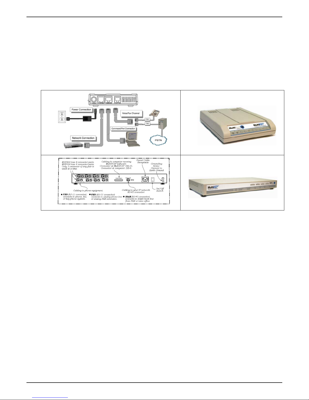
Beyond general setup information (like Mechanical Installation, & Cabling, LED definitions, and other
general info which are presented in the MultiVOIP User Guide & Quick Start Guide), this software guide
presents all the information you need to configure your MultiVOIP for use in a Communication Manager
system. It presents information on the MultiVOIP software screens as well as the related Communication
Manager screens. The MultiVOIP User Guide remains valuable as a reference source.
MultiVOIPs in Avaya Communication Manager Systems
The Communication Manager build of the MultiVOIP software allows for use of MultiVOIP units in
conjunction with IP-equipped Avaya PBX units. These PBXs are equipped with H.323 gatekeeper
functionality and support endpoints such as IP phones and MultiVOIP gateways.
In addition to functioning as a gateway, the MultiVOIP also contains an integrated gatekeeper, except
MVP130 Models. This allows the MultiVOIP to serve as it’s own alternate gatekeeper should
Communication Manager be unavailable. When serving as an alternate gatekeeper, the MultiVOIP
processes registration and call routing for it’s local FXS/FXO/DID ports as well as local Avaya IP phones.
This is the MultiVOIP’s “gatekeeper survivability” mode.
Each MultiVOIP voice channel can be registered with a primary Communication Manager gatekeeper or
one of two optional alternate gatekeepers. The optional gatekeepers can be other Communication Manager
gatekeepers or the integrated MultiVOIP gatekeeper.
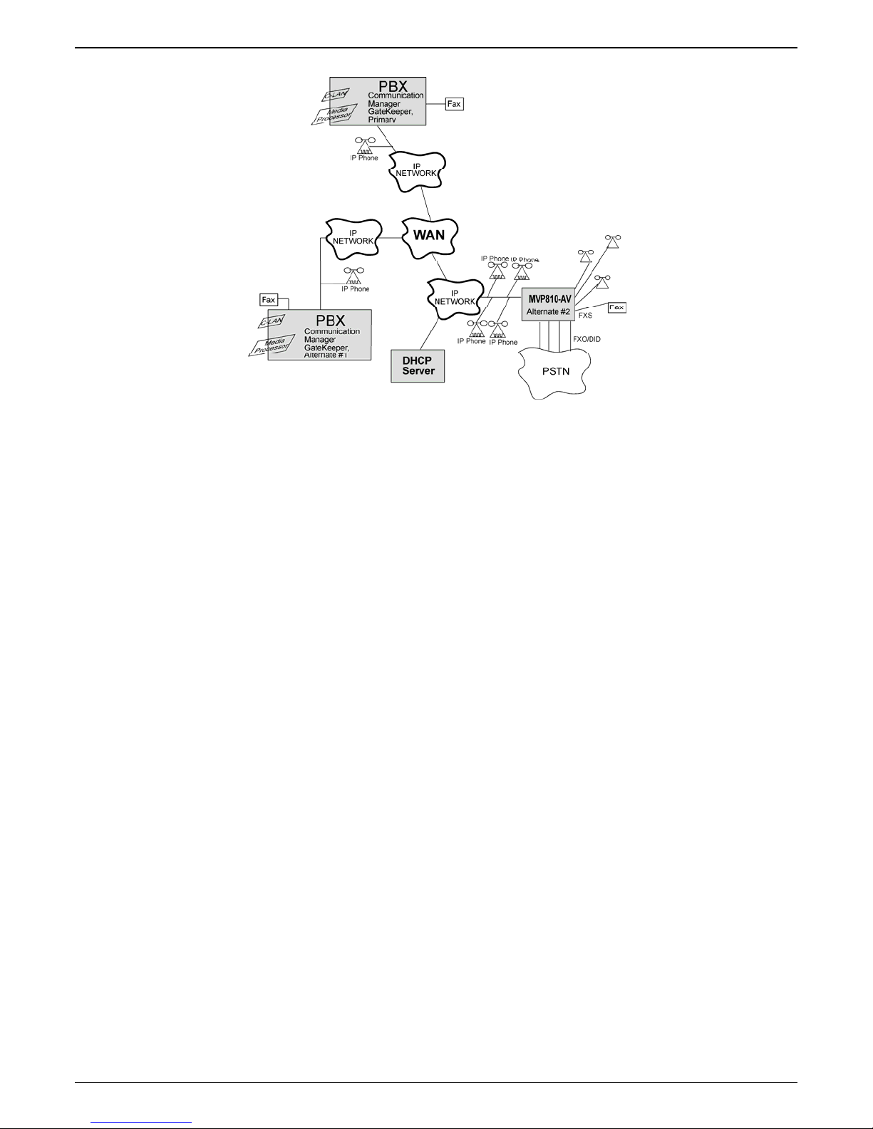
The diagram below shows a common function for the MultiVOIP unit within the Communication Manager
network: the MultiVOIP allows selected callers at a site remote from the Avaya PBX units to have access to
the PBX units and all of their extensions without tolls. Voice and fax calls are supported.
4 Multi-Tech Systems, Inc. Avaya Communication Manager Guide
Page 5
Chapter 1 - Introduction
Figure 1. MultiVOIP in Avaya Communication Manager System
The MVP810-AV shown in the diagram on the previous page functions as a gateway registered to one of
the Communication Managers in the IP network. The MVP810-AV provides survivable calling between the
IP Phones, stations (FXS) and trunk (FXO/DID) ports at the remote site should the WAN link go down.
The MultiVOIP will not serve as a survivable gatekeeper for IP phones on the other side of the wan link.
If the WAN link goes down, the MultiVOIP will try to register six times with the Primary Communication
Manager Gatekeeper at 3-second intervals. If the Primary gatekeeper does not respond, the MultiVOIP will
try to register with the Alternate #1 Communication Manager Gatekeeper six times at 3-second intervals. If
the alternate #1 gatekeeper does not respond, the MultiVOIP will register with the Alternate #2 gatekeeper,
which is the integrated MultiVOIP gatekeeper. If the MultiVOIP registers to its own gatekeeper, this is
gatekeeper survivability mode where the MultiVOIP will process registration and call routing for its local
FXS/FXO/DID ports as well as local Avaya IP phones.
While in gatekeeper survivability mode, the MultiVOIP checks for the availability of the primary
Communication Manager gatekeeper every 3-minutes. The MultiVOIP will re-register and discontinue its
survivability mode automatically when the primary Communication Manager gatekeeper becomes
available. Any calls that were established during the "survivable mode" which are still active while the
MultiVOIP gateway returns to "subtending mode" to the CM gatekeeper, shall be preserved by the
MultiVOIP gatekeeper. When these calls become inactive (idle), the MultiVOIP gatekeeper shall force these
endpoints to unregister with the MultiVOIP gatekeeper and re-register with the CM gatekeeper.
If the MultiVOIP is not configured as an alternate gatekeeper, and none of the Primary, Alternate #1, or
Alternate #2 CM gatekeepers respond, the MultiVOIP will enter gateway survivable mode (if enabled) and
will process calls according to it’s inbound and outbound phone books. In gateway survivable mode, the
MultiVOIP will check for the availability of the primary Communication Manager gatekeeper according to
the Switching Time Interval programmed into the Communication Manager Parameters screen of the
MultiVOIP configuration. The MultiVOIP will exit gateway survivability mode if it is able to register with
the Primary CM gatekeeper. Gateway survivability mode is enabled by checking the “Enable Survivability
Mode” checkbox in the Communication Manager Parameters screen. If IP phone survivability is required,
you must enable gatekeeper survivability mode instead by configuring the MultiVOIP as one of the
alternate #1 or alternate #2 gatekeepers.
The following Avaya IP Phone models are supported in gatekeeper survivable mode:
4601 4602 4606 4610 4612 4620 4621 4622 4624 4625
9610 9620 9630 9640 9650
1603 1608 1616
Multi-Tech Systems, Inc. Avaya Communication Manager Guide 5
Page 6
Chapter 2 – Configuration
Chapter 2 - Configuration
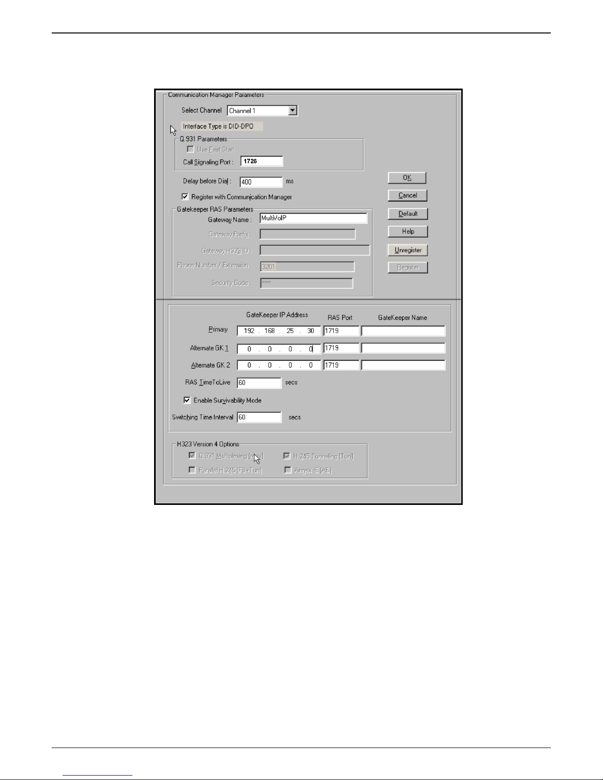
Configuring MultiVOIP for Avaya Communication Manager Use
To configure the MultiVOIP unit within such a system (similar to that in Figure 1), use the Communication
Manager Parameters
Gatekeeper” is selected, then many parameters must assume default values and those will be grayed out on
the screen. In setting up the MultiVOIP unit for Communication Manager use, bear in mind that you may
configure the MultiVOIP to operate with any combination of stations (FXS) and/or trunks (FXO/DID).
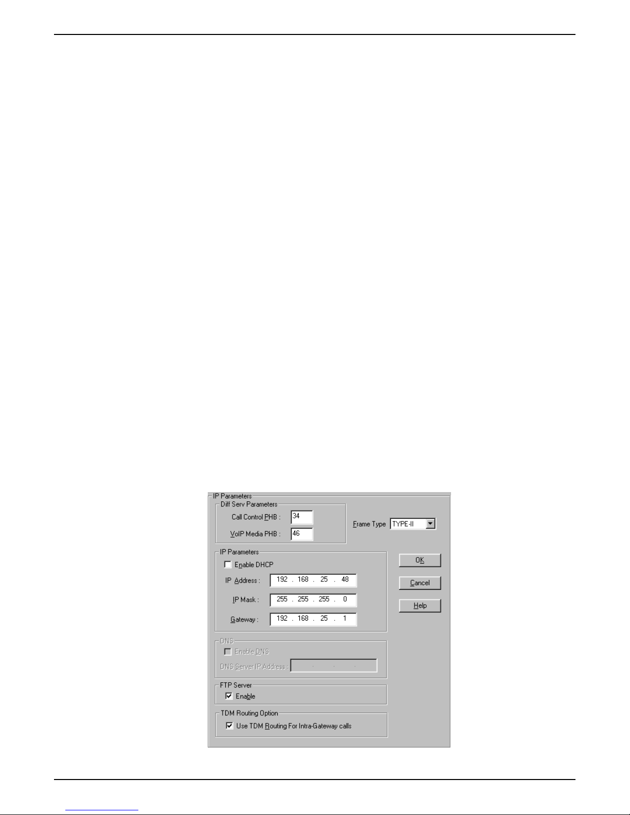
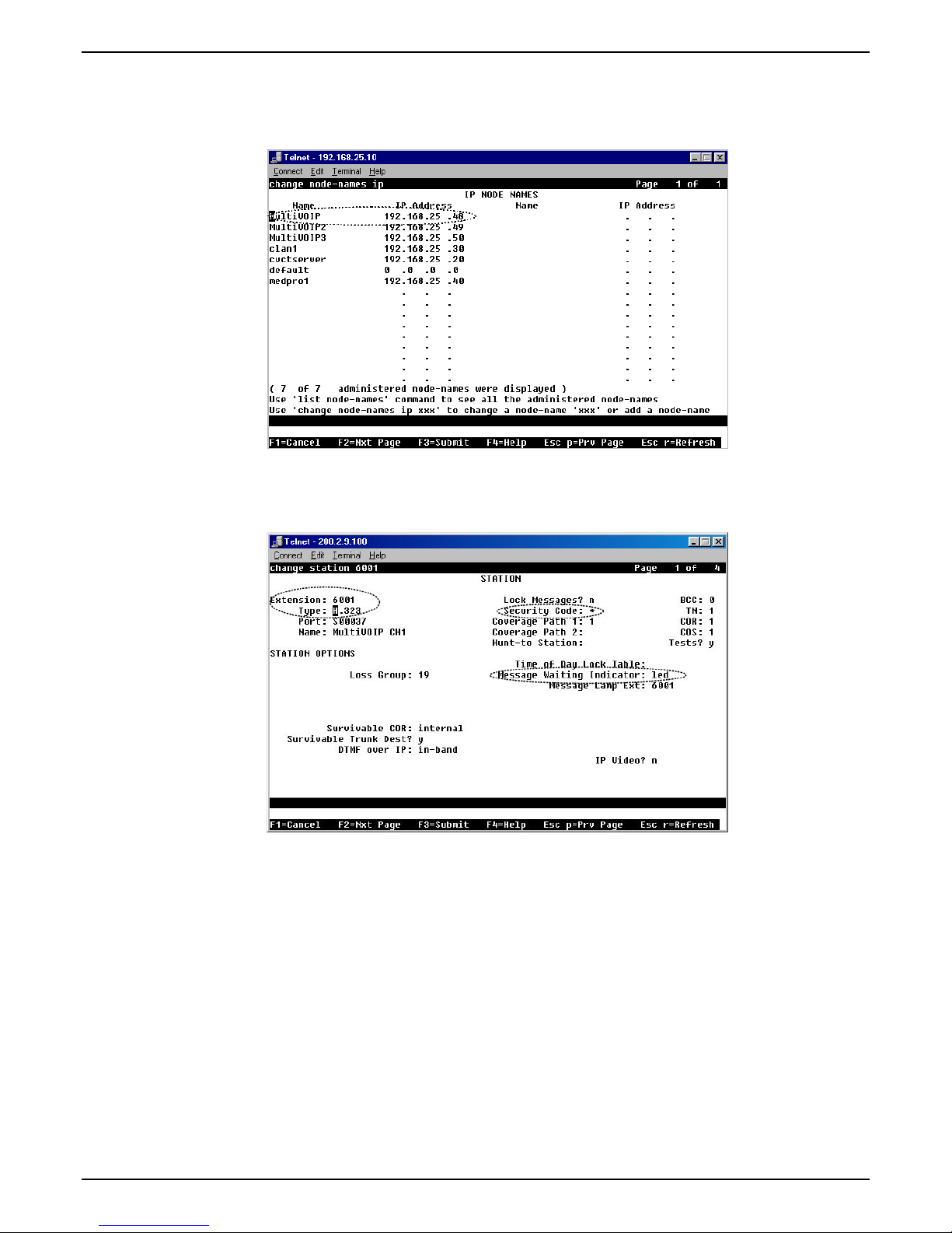
1. Configure IP Parameters
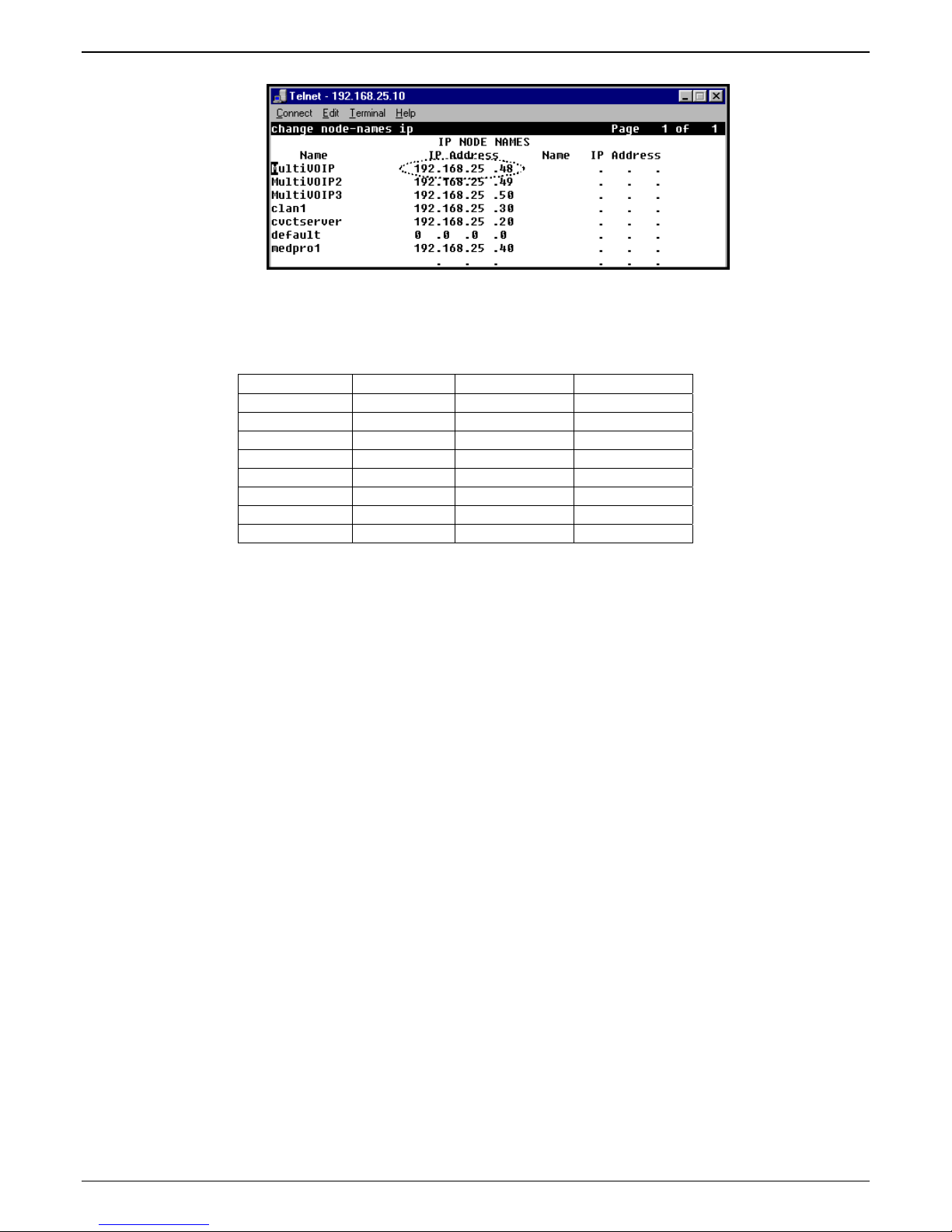
1a. Configure the IP address, gateway address, and mask used by the MultiVOIP unit in the
Configuration |IP Parameters screen of the MultiVOIP program. The IP address must match that
used in the Communication Manager “Change Node Names IP” form (dialog box).
1b. DiffServ PHB (Per Hop Behavior) values pertain to a differential prioritizing system for IP packets
as handled by DiffServ-compatible routers. There are 64 values, each with an elaborate technical
description.
purposes, in RFC3246, which describes the value 34 (34 decimal; 22 hex) for Assured Forwarding
behavior (default for Call Control PHB) and the value 46 (46 decimal; 2E hexadecimal) for
Expedited Forwarding behavior (default for Voip Media PHB).
If you wish to use just one DiffServ PHB value, Ayaya recommends the value 46 (46 decimal; 2E
hex) for both Call Control and VOIP Media.
screen within the MultiVOIP program. If “Register with Communication Manager
These descriptions are found in TCP/IP standards RFC2474, RFC2597, and, for present
1c. If you require that the MultiVOIP get its IP address from a DHCP server, select the “Enable DHCP”
option. The DHCP server must be located at the same site as the MultiVOIP so it is available in the
event of wan link failure. The DHCP server must issue an IP address that is statically defined on
the DHCP server so that the MultiVOIP gets the same IP address all the time.
1d. TDM Routing Option. Calls placed between ports on the same MultiVOIP voice channel board
will normally be routed over the MultiVOIP’s internal TDM (Time Division Multiplexed) bus. TDM
calls have less delay than calls routed over IP. On MVP410/810-AV models, calls between channels
1-4 or channels 5-8 will be TDM routed. Calls between voice boards (for example, channel 1 calling
channel 5) will be IP routed. If you require all calls to be IP routed, disable the “use TDM Routing
for Intra-Gateway Calls” option. This should not normally be required, so it is recommended that
you leave TDM Routing enabled.
6 Multi-Tech Systems, Inc. Avaya Communication Manager Guide
Page 7
Chapter 2 - Configuration
1e. TCP/UDP port requrements. To ensure proper functioning of the MultiVOIP, the TCP/UDP
network connection must not be blocked on the network connection between the MultiVOIP and
CM.
The UDP ports used by the MultiVOIP are as follows:
Channel RTP Port RTCP Port T38 Port
1 5006 5007 5008
2 5016 5017 5018
3 5026 5027 5028
4 5036 5037 5038
5 5046 5047 5048
6 5056 5057 5058
7 5066 5067 5068
8 5076 5077 5078
The TCP ports used by the MultiVOIP are as follows:
H.225 Listen Port – User configured for each channel in the CM Settings screen (default 1721 –
1728)
H.225 Client Port – Dynamic (16000 – 20000)
H.245 Listen Port – Dynamic (16000 – 20000)
RAS Client Port – Dynamic (16000 – 20000)
1f. Emergency Transfer. Emergency transfer allows local analog telephones to access the local CO and
to answer telephone calls during a power failure.
For the various products the features operate as follows:
MVP210-AV
Port 1 is connected to Port 2
MVP410-AV
Port 1 is connected to Port 2
Port 3 is connected to Port 4
MVP810-AV
Port 1 is connected to Port 2
Port 3 is connected to Port 4
For example, suppose ports 1 and 3 of MVP410-AV are configured as FXS with telephones
attached. Ports 2 and 4 are configured as FXO trunks with CO lines attached. If there is a power
failure, the telephones on ports 1 and 3 would automatically be connected to the CO lines attached
to ports 2 and 4 allowing inbound and/or outbound call to be make.
Note: This feature shall only be available on “AV” models of the gateway that are:
Rev B: For the MVP410 and MVP810 models
Rev B: For the MVP210 model
Multi-Tech Systems, Inc. Avaya Communication Manager Guide 7
Page 8
Chapter 2 – Configuration
2. Configure Interface Parameters.
2a. Determine which voice channels will be stations (FXS), trunks (FXO/DID), or disabled. Configure
them as such in the
Configuration | Interface screen of the MultiVOIP GUI.
2b. If you are configuring a DID-DPO (Direct Inward Dial – dial-pulse originating) interface for DID
incoming calls, you need to chose DID-DPO from the pull down menu for Interface Type. You also
have to set the DID Options Start Modes; Immediate Start, Wink Start, or Delay Dial.
Immediate Start allows the MultiVOIP to detect the off-hook condition at the originating end of the
call and becomes ready to receive the digits immediately.
Wink Start allows the MultiVOIP to detect the off-hook condition at the originating end of the call.
The MultiVOIP then reverses the battery polarity for a specified time (140-290 ms; a “wink”) and
then becomes ready to receive the dialed digits. You can select the Wink Timer duration (140 to 290
ms).
Delay Dial allows the MultiVOIP to detect the off-hook condition at the originating end of the call.
Then the MultVOIP reverses battery polarity for a specified time (reverse polarity duration has a
wider acceptable range than Wink Start) and then becomes ready to receive dialed digits.
2c. Enable the “Message Waiting Light” feature if you have FXS Interface selected and are using an
Avaya analog telephone with Message Waiting indicator or enable “Stutter Dial Tone” if you are
8 Multi-Tech Systems, Inc. Avaya Communication Manager Guide
Page 9

Chapter 2 - Configuration
using a non-Avaya analog telephone. This station must be properly administered in the Audix
Voice Mail System for the message waiting feature to work.
2d. Activate the “Caller ID” feature if you have FXS Interface selected and are using an analog
telephone with caller ID display. The MultiVOIP will output Caller ID information, if received,
between the first and second rings.
2e. Activate “Caller ID” on FXO interfaces if the attached line supports it. The MultiVOIP will capture
the Caller ID information, if provided, between the first and second rings and will forward the
information to CM.
Note: If the CM customer is operating on CM release 2.0.1 (or newer), remember that for the ‘h323’
specified station, the following CM admin fields must be set appropriately:
a) The ‘Message Waiting’ field must be enabled and set to “led” if this feature is intended to be
supported on the MultiVOIPs analog station port.
b) Similarly, the following features must be enabled as desired:
• Switchhook flash
• Call Waiting Indication
• Attendant Call Waiting Indication
Multi-Tech Systems, Inc. Avaya Communication Manager Guide 9
Page 10
Chapter 2 – Configuration
3. Configure Voice/Fax Parameters.
3a. In the MultiVOIP’s
Configuration | Voice/Fax Parameters screen, configure the voice channels for a
voice coder that is supported by Communication Manager.
The voice coder selected must match the voice coders listed in the ip-codec-set for the network
region the MultiVOIP resides in. If only G.729 is listed in the ip-codec-set, select G.729 on the
MultiVOIP. If G.711 is listed before G.729 in the ip-codec-set, select G.711, G.729 on the MultiVOIP.
If G729 is listed before G.711 in the ip-codec-set, select G.729, G.711 on the MultiVOIP.
There is one exception, if only G.711 is listed in the ip-codec-set, you must select G.711, G.729 on
the MultiVOIP. This will allow support for G.711 for CM managed calls, and will allow support for
G.729 for survivable mode calls. The MultiVOIP only supports G.729 in survivable mode.
The table below shows the bandwidth required per voice channel based on the codec selected and
the CM “Frames per Packet” setting in the “Change IP-Codec-Set” screen.
Bandwidth per Channel
Voice Frames per IP Packet
Coder 1 2 3 4
G.729 40K bps 24K bps 18K bps 16K bps
G.711 96K bps 80K bps 74.7K bps 72K bps
3b. If the CM customer desires that a particular FXS port is to operate as a “hot extension”, set the
“auto call/off-hook alerting” feature to auto call and enter the desired destination number in the
“phone number” field. Enabling this feature allows an analog phone user to be able to lift his/her
10 Multi-Tech Systems, Inc. Avaya Communication Manager Guide
Page 11
Chapter 2 - Configuration
handset (and without dialing the number) immediately call the far-end party. To prevent toll fraud
on FXO trunk ports, set the “autocall enable” feature and enter the phone number for a receptionist
or auto-attendent.
3c. The MultiVOIP supports off-hook alerting on FXS ports. To enable the feature, set the “auto
call/off-hook alert” feature to “off-hook alert” and enter the destination number in the “phone
number” field. If the user lifts the handset, but does not dial a number, dial tone will be heard for
10 seconds, followed by intercept tone for the number of seconds configured in the “off-hook alert
timer” field. If this timer expires, a call will automatically be placed to the destination number in
the “phone number” field.
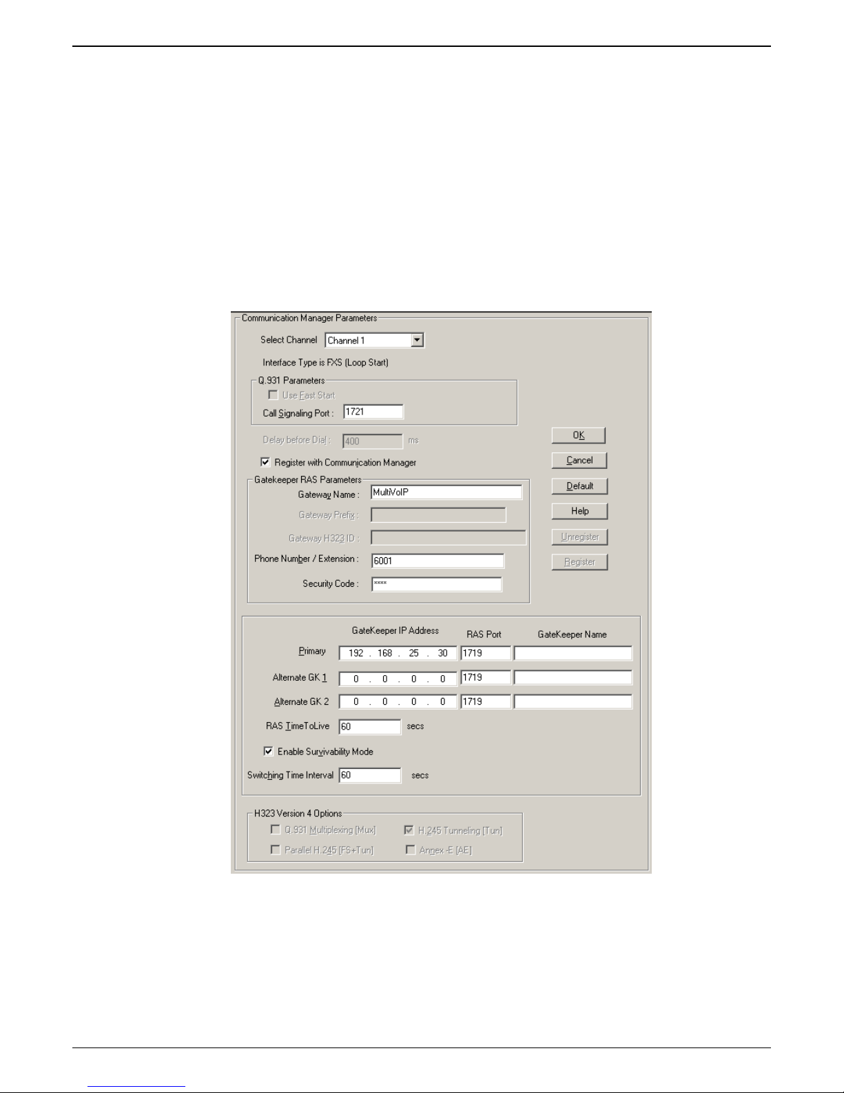
4. Configure the station (FXS) channels in the
Communication Manager MultiVOIP: FXS Channels
Communication Manager Parameters screen.
4a. Make sure the “Register with Communication Manager Gatekeeper” option is checked.
4b. Configure Call Signaling Port. This needs to be unique on each registered FXS channel and must
fall within the range of port values supported by Communication Manager. Typically, it is OK to
use the default values 1721-1728 on channels 1-8 respectively.
Multi-Tech Systems, Inc. Avaya Communication Manager Guide 11
Page 12
Chapter 2 – Configuration
4c. Configure Gateway Name (optional). This is the name that gets displayed when viewing Call
Progress statistics for this channel. If used, the MultiVOIP’s Gateway Name must match the
name used in the Communication Manager “Node-Names IP” form.
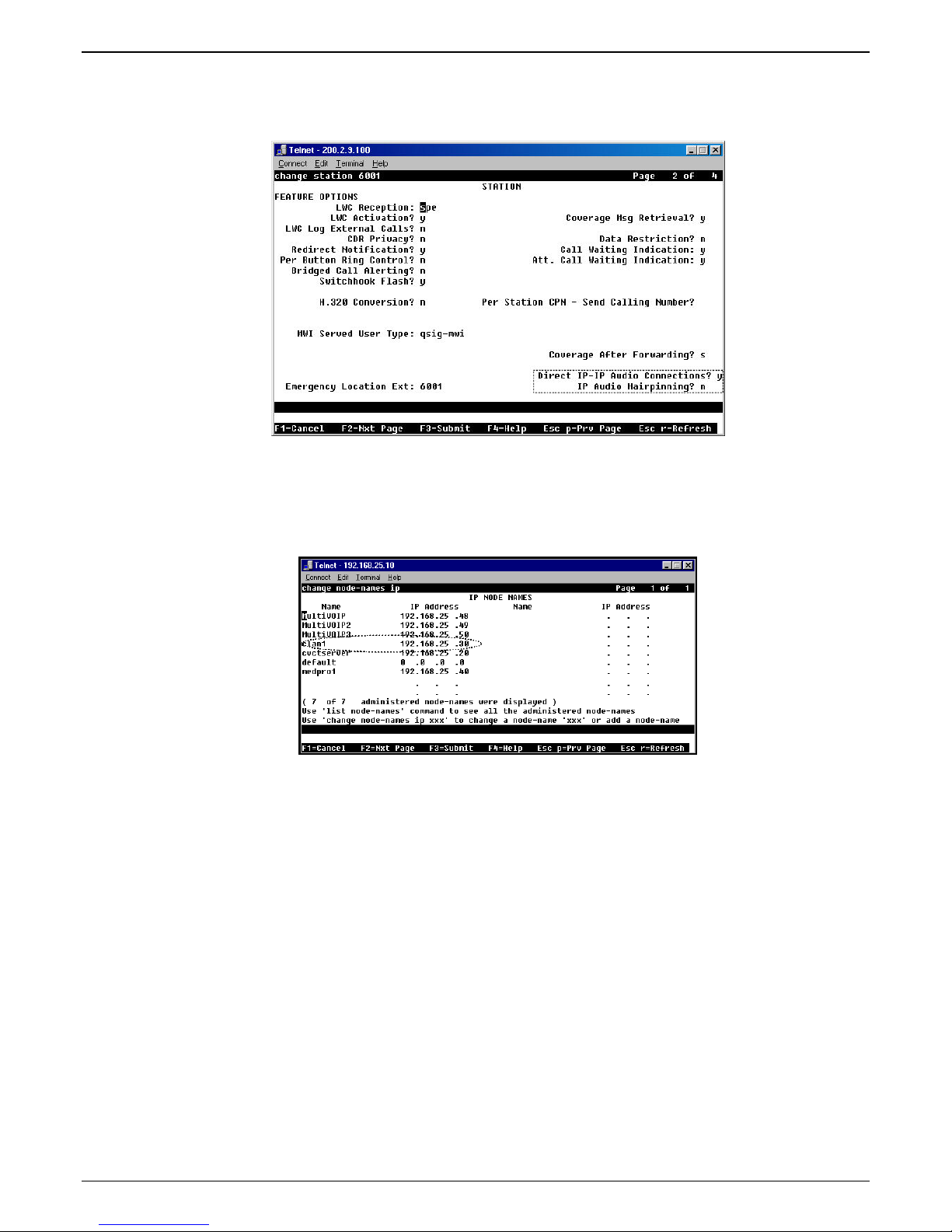
4d. Configure Phone Number / Extension. This must match the extension configured for this station
in the Communication Manager “station” form. If “ Message Waiting Indicator” is required for this
extension, set this option to “led” in the CM “station” form.
12 Multi-Tech Systems, Inc. Avaya Communication Manager Guide
Page 13
Chapter 2 - Configuration
Note that, in page 2 of the Communication Manager “Station” form, the “Direct IP-IP Audio
Connection” field must be set to “y” and the “IP Audio Hairpinning” field must be set to “n.”
4e. Configure Security Code. This must match the security code configured in the Communication
Manager “Station” form (see first graphic in step 4d).
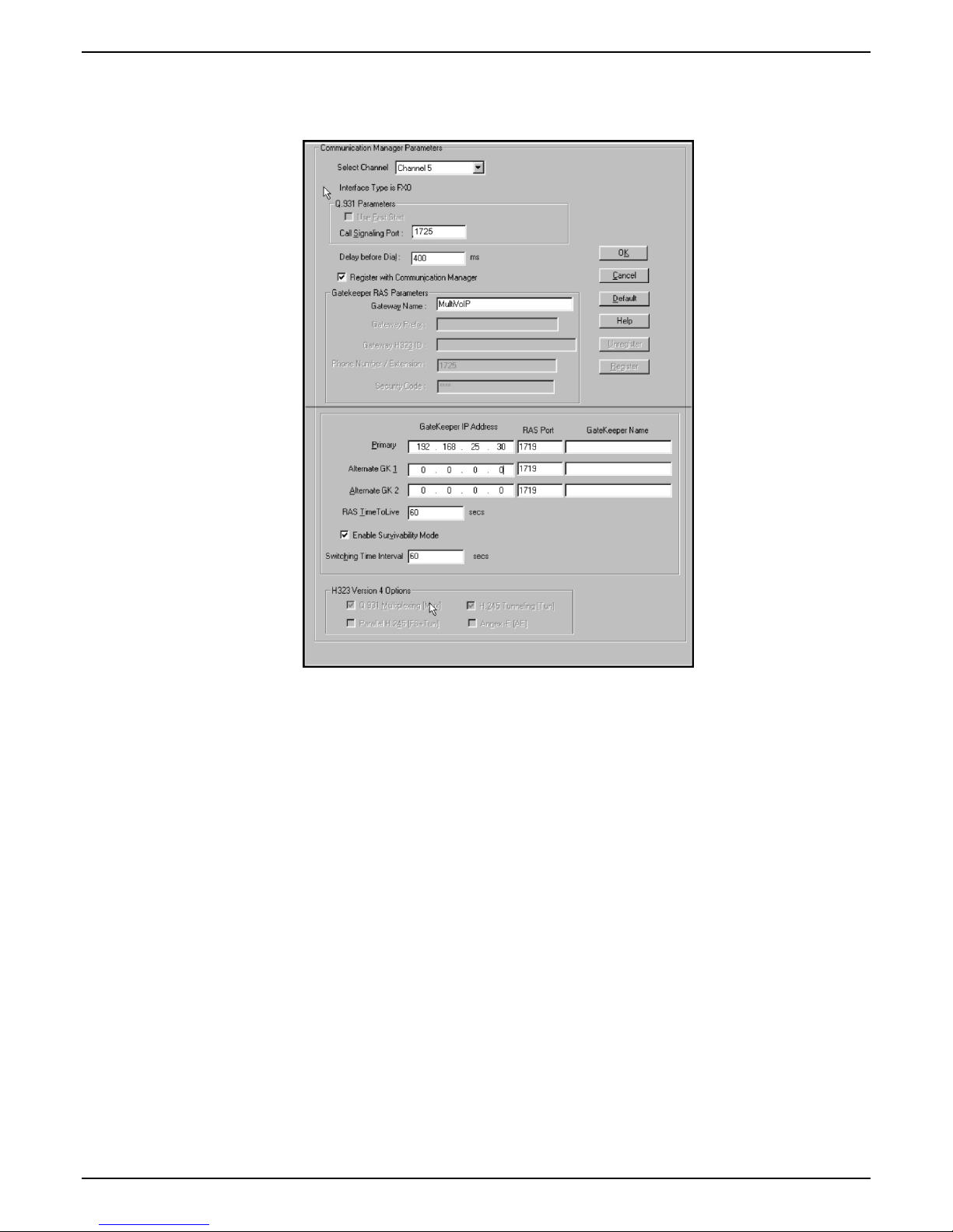
4f. Configure Primary Gatekeeper IP Address. This must be configured to match the IP address of the
CLAN or PROCR card in the “IP Node Names” form of the primary CM gatekeeper. Do not
change the RAS port from the default 1719 and leave the Gatekeeper Name field blank.
4g. Configure IP addresses for Alternate Gatekeeper 1 and Alternate Gatekeeper 2 (optional). These
must be configured to match the IP address of the respective CLAN or PROCR card in the PBX unit
serving as the Alternate Gatekeeper. This field appears in IP Node Names form of the
Communication Manager software for that PBX. If you are using the MultiVOIP Gatekeeper as an
alternate gatekeeper, enter the IP address of the MultiVOIP. The alternate MultiVOIP gatekeeper
must appear after any Communication Manager alternate gatekeepers.
Multi-Tech Systems, Inc. Avaya Communication Manager Guide 13
Page 14
Chapter 2 – Configuration
5. Configure trunk (FXO) channels in the Communication Manager Parameters screen.
Communication Manager MultiVOIP: FXO Channels
5a. Make sure the “Register with Communication Manager Gatekeeper” option is checked.
14 Multi-Tech Systems, Inc. Avaya Communication Manager Guide
Page 15
Chapter 2 - Configuration
5b. Configure Call Signaling Port. Unlike station (FXS) ports, which require a unique value for each
channel, trunk (FXO) ports require that the same Call Signaling Port value be used on all trunk
(FXO) ports that are registered to the same Communication Manager PBX. Configure this to a
unique value that is not being used by another station (FXS) or trunk (DID) port on this MultiVOIP
unit. This port value must fall within the range of port values supported by Communication
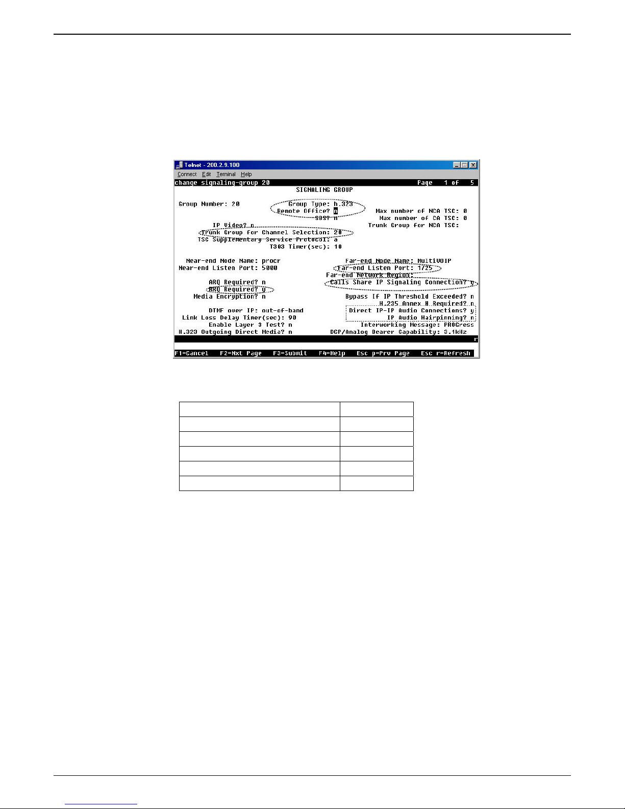
Manager and should match the “Far-end Listen Port” value configured in the Communication
Manager “Signaling Group” (“Display Signaling Group”) form (dialog box). All FXO ports on this
MultiVOIP will use the same Signaling Group for communication with the CM Server.
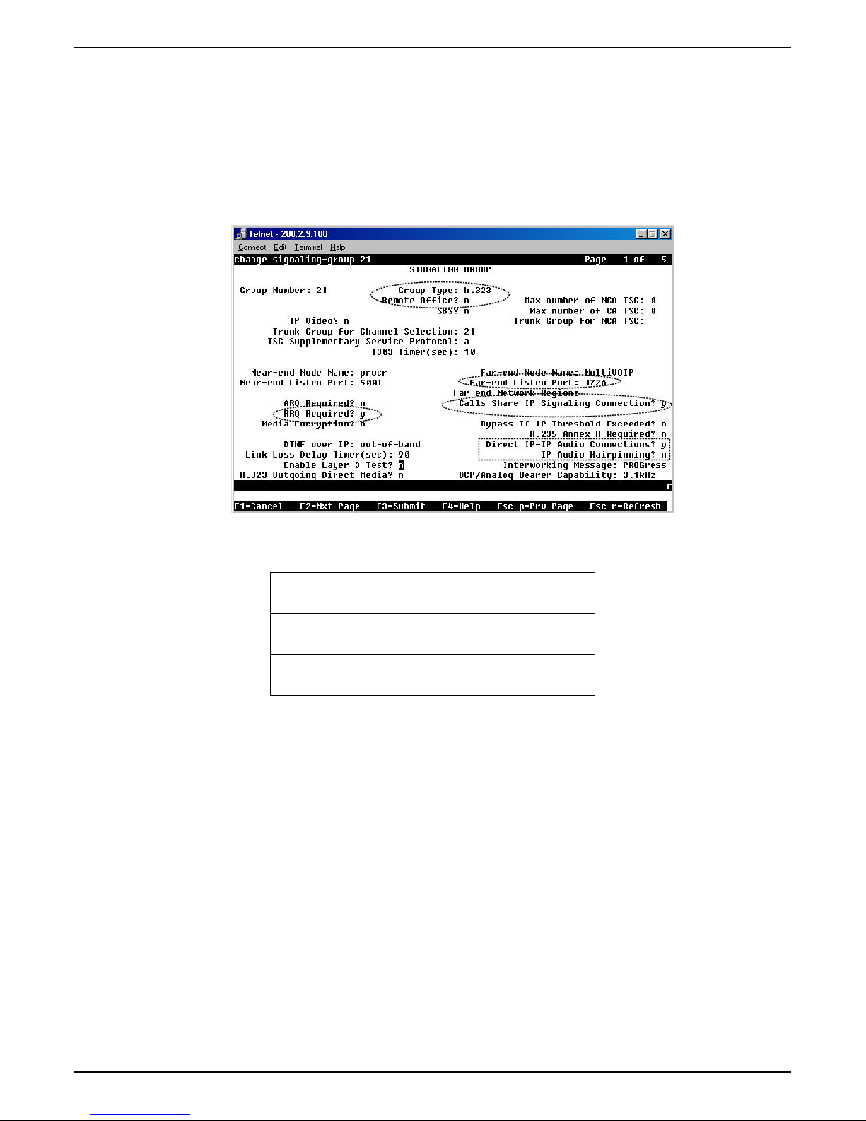
Note that several other fields in the Communication Manager “Signaling Group” form (dialog box)
must be set to accommodate operation with the MultiVOIP:
Group Type = h.323
Remote Office? = n
RRQ Required? = y
Direct IP-IP Audio Connection? = y
IP Audio Hairpinning? =n
Calls Share IP Sig Connection =y
5c. Configure Delay before Dial value. This is the delay after the MultiVOIP goes off hook before it
dials a number to the attached PSTN line. Some PSTN lines may require more than the default 400
ms value. Configure as appropriate for the PSTN lines you are using. If you are not sure, leave the
default value in place.
5d. Configure Gateway Name. This should match the value configured for this MultiVOIP unit in the
Communication Manager “IP Node Names” and “Signaling Group” forms.
5e. Configure Primary Gatekeeper IP Address. This must be configured to match the IP address of the
CLAN or PROCR card in the “IP Node Names” form of the primary Communication Manager
Gatekeeper unit. Do not change the RAS Port and leave the Gatekeeper name field blank.
5f. Configure IP addresses for Alternate Gatekeeper1 and Alternate Gatekeeper 2 (optional). These
must be configured to match the IP address of the respective CLAN or PROCR card in the PBX unit
serving as the Alternate Gatekeeper. This field appears in IP Node Names form of the
Communication Manager software for that PBX. If you are using the MultiVOIP Gatekeeper as an
alternate gatekeeper, enter the IP address of the MultiVOIP. The alternate MultiVOIP gatekeeper
must appear after any Communication Manager alternate gatekeepers.
Multi-Tech Systems, Inc. Avaya Communication Manager Guide 15
Page 16
Chapter 2 – Configuration
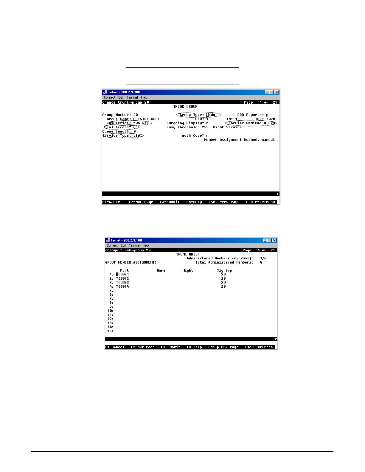
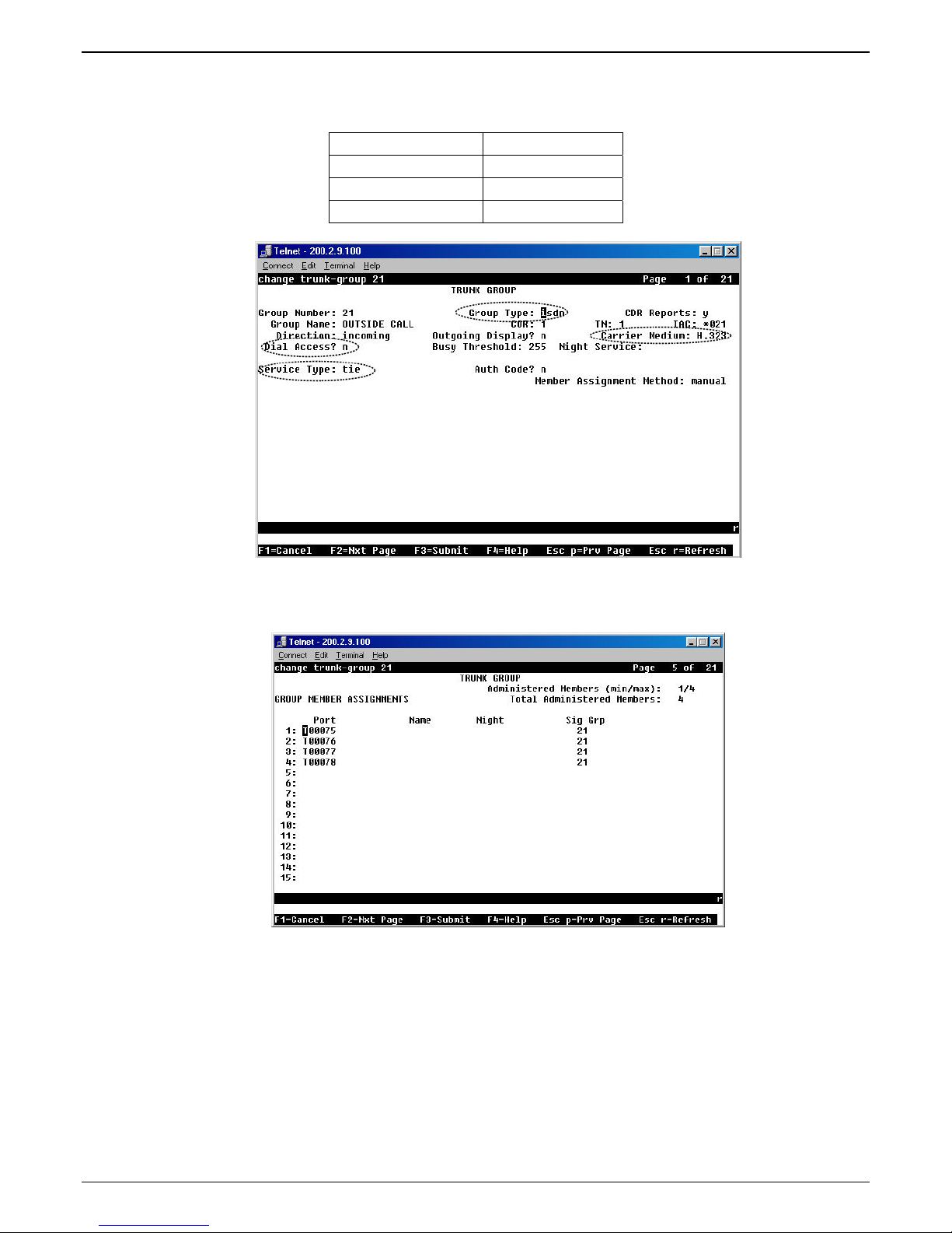
5g. To accommodate the MultiVOIP unit, the following fields in the Communication Manager “Trunk
Group – Page 1” form must be set as shown:
Dial Access? = y
Service Type = tie
Group Type = ISDN
Carrier Medium = IP/H.323
5h. To accommodate the MultiVOIP unit, all of the MultiVOIP’s FXO channels must be listed as trunk-
group members in the Communication Manager Trunk Group form (“Change Trunk-Group” dialog
box).
For example, if four channels of an MVP810-AV are configured as FXO, four trunk group numbers
must be listed, as above.
16 Multi-Tech Systems, Inc. Avaya Communication Manager Guide
Page 17
Chapter 2 - Configuration
6. Configure trunk (DID) channels in the Communication Manager Parameters screen.
Communication Manager MultiVOIP: DID Channels
6a. Make sure the “Register with Communication Manager Gatekeeper” option is checked.
Multi-Tech Systems, Inc. Avaya Communication Manager Guide 17
Page 18
Chapter 2 – Configuration
6b. Configure Call Signaling Port. Unlike station (FXS) ports, which require a unique value for each
channel, trunk DID ports require that the same Call Signaling Port value be used on all DID trunk
ports that are registered to the same Communication Manager PBX. Configure this to a unique
value that is not being used by another station (FXS) or trunk (FXO) port on this MultiVOIP unit.
This port value must fall within the range of port values supported by Communication Manager
and should match the “Far-end Listen Port” value configured in the Communication Manager
“Signaling Group” (“Display Signaling Group”) form (dialog box). All DID trunk ports on this
MultiVOIP will use the same Signaling Group for communication with the CM Server.
Note that several other fields in the Communication Manager “Signaling Group” form (dialog box)
must be set to accommodate operation with the MultiVOIP:
Group Type = h.323
Remote Office? = n
RRQ Required? = y
Direct IP-IP Audio Connection? = y
IP Audio Hairpinning? = n
Calls Share IP Sig Connection =y
6c. Configure Gateway Name. This should match the value configured for this MultiVOIP unit in the
Communication Manager “IP Node Names” and “Signaling Group” forms.
6d. Configure Primary Gatekeeper IP Address. This must be configured to match the IP address of the
CLAN or PROCR card in the “IP Node Names” form of the primary Communication Manager
Gatekeeper unit. Do not change the RAS Port and leave the Gatekeeper name field blank.
6e. Configure IP addresses for Alternate Gatekeeper1 and Alternate Gatekeeper 2 (optional). These
must be configured to match the IP address of the respective CLAN or PROCR card in the PBX unit
serving as the Alternate Gatekeeper. This field appears in IP Node Names form of the
Communication Manager software for that PBX. If you are using the MultiVOIP Gatekeeper as an
alternate gatekeeper, enter the IP address of the MultiVOIP. The alternate MultiVOIP gatekeeper
must appear after any Communication Manager alternate gatekeepers.
18 Multi-Tech Systems, Inc. Avaya Communication Manager Guide
Page 19
Chapter 2 - Configuration
6f. To accommodate the MultiVOIP unit, the following fields in the Communication Manager “Trunk
Group – Page 1” form must be set as shown:
Dial Access? = n
Service Type = tie
Group Type = ISDN
Carrier Medium = IP/H.323
6g. To accommodate the MultiVOIP unit, all of the MultiVOIP’s DID channels must be listed as trunk-
group members in the Communication Manager Trunk Group form (“Change Trunk-Group”
dialog box).
For example, if four channels of an MVP810-AV are configured as DID, four trunk group numbers
must be listed, as above.
Multi-Tech Systems, Inc. Avaya Communication Manager Guide 19
Page 20
Chapter 2 – Configuration
7. Configure MultiVOIP gatekeeper (except for the MVP130 Models) to provide survivability to IP phones
and local FXS/FXO/DID ports.
If you are using Avaya IP phones in addition to the MultiVOIP, you must configure the MultiVOIP
gatekeeper to provide survivability for the IP phones and local FXS/FXO/DID ports in the event of
WAN link failure.
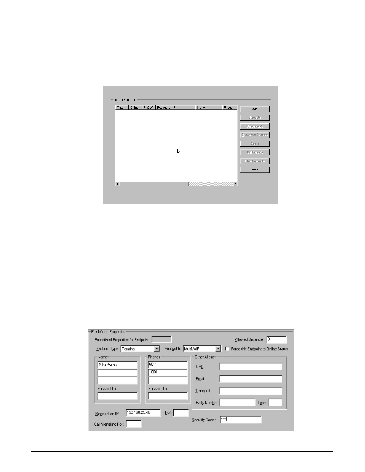
7a. In the MultiVOIP’s Gatekeeper |Endpoints screen, add predefined endpoints to the gatekeeper.
One endpoint entry is required for each FXS port or IP phone. Only one entry is required for one or
more FXO ports per MultiVOIP gateway. Only one entry is required for one or more DID ports per
MultiVOIP gateway.
7b. To add an entry for a MultiVOIP FXS port, configure Endpoint Type, Product ID, Names, Phones,
Registration IP, and Security code fields as indicated below. Configure the Names field with a
unique descriptive identifier. The information contained in the Names and Phones fields will be
used for Caller ID purposes in survivable mode. Configure Phones and Security Code to match the
values configured for this station in Communication Manager. The Registration IP should match
the IP address of the MultiVOIP where the FXS port is located. This could be the IP address of this
very same MultiVOIP or another MultiVOIP. Leave the other fields blank. One entry is required for
each MultiVOIP FXS port that is configured to register with Communication Manager. Click OK to
accept this entry. Repeat the above steps to add additional FXS station port entries.
If the autocall feature is being used to route incoming FXO trunk calls to an extension (1000, etc.,) at
the main site, you can program a second entry in the “Phones” field to 1000 to route incoming FXO
trunk calls to a given FXS station to cover the autocall situation in Gatekeeper Survivable mode.
20 Multi-Tech Systems, Inc. Avaya Communication Manager Guide
Page 21
Chapter 2 - Configuration
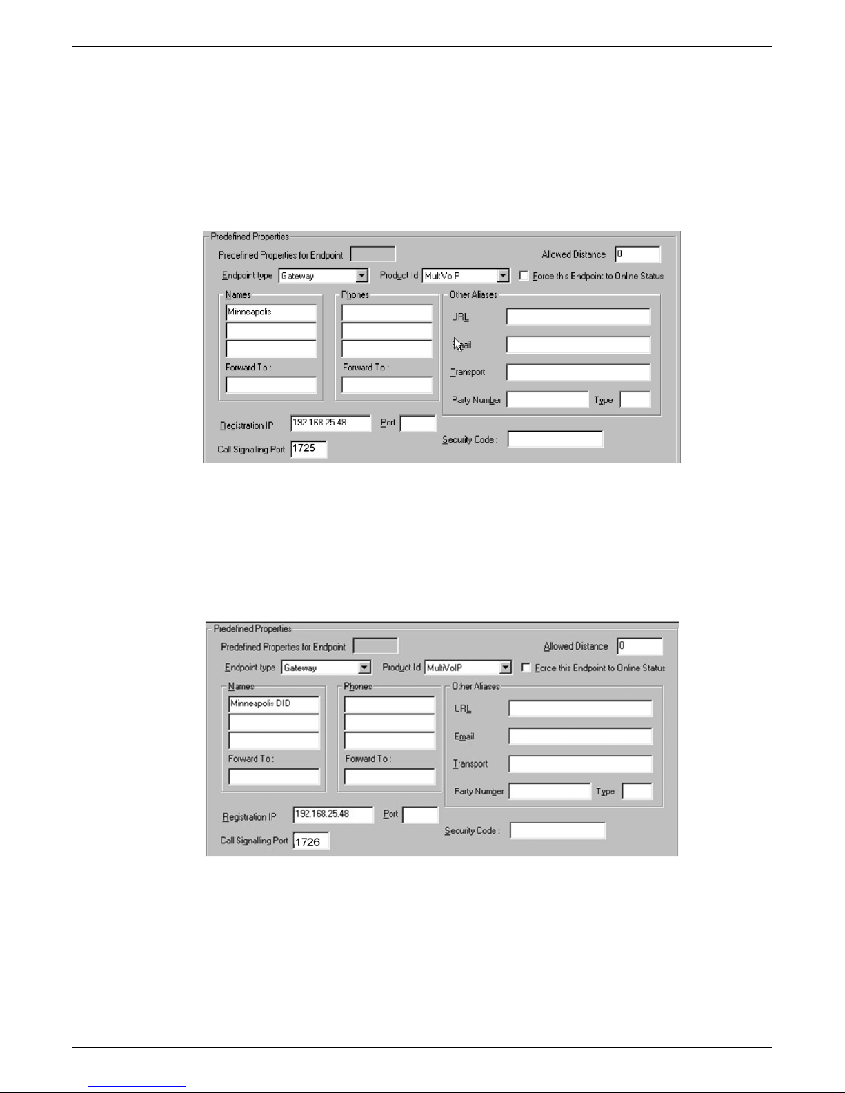
7c. To add an entry for MultiVOIP FXO ports, configure Endpoint Type, Product ID, Names,
Registration IP, and Call Signalling Port fields as indicated below. Configure the Names field
with a unique descriptive identifier for the FXO trunk. This same name will be used later to map
Outbound Phone Book entries with specific digit patterns (area codes, etc.) to this FXO trunk, and
for Caller ID purposes in survivable mode. The Registration IP should match the IP address of the
MultiVOIP where the port is located. This could be the IP address of this very same MultiVOIP or
another MultiVOIP. Leave the other fields blank. Only one entry is required for one or more ports
on a given MultiVOIP. For example, if the MultiVOIP has four FXO ports, only one gatekeeper
entry should be added. Click OK to accept this entry.
7d. To add an entry for MultiVOIP DID ports, configure Endpoint Type, Product ID, Names,
Registration IP, and Call Signalling Port fields as indicated below. Configure the Names field
with a unique descriptive identifier for the DID trunk. This name will be used for Caller ID
purposes in survivable mode. The Registration IP should match the IP address of the MultiVOIP
where the DID port is located. This could be the IP address of this very same MultiVOIP or another
MultiVOIP. Leave the other fields blank. Only one entry is required for one or more ports on a
given MultiVOIP. For example, if the MultiVOIP has four DID ports, only one gatekeeper entry
should be added. Click OK to accept this entry.
Multi-Tech Systems, Inc. Avaya Communication Manager Guide 21
Page 22
Chapter 2 – Configuration
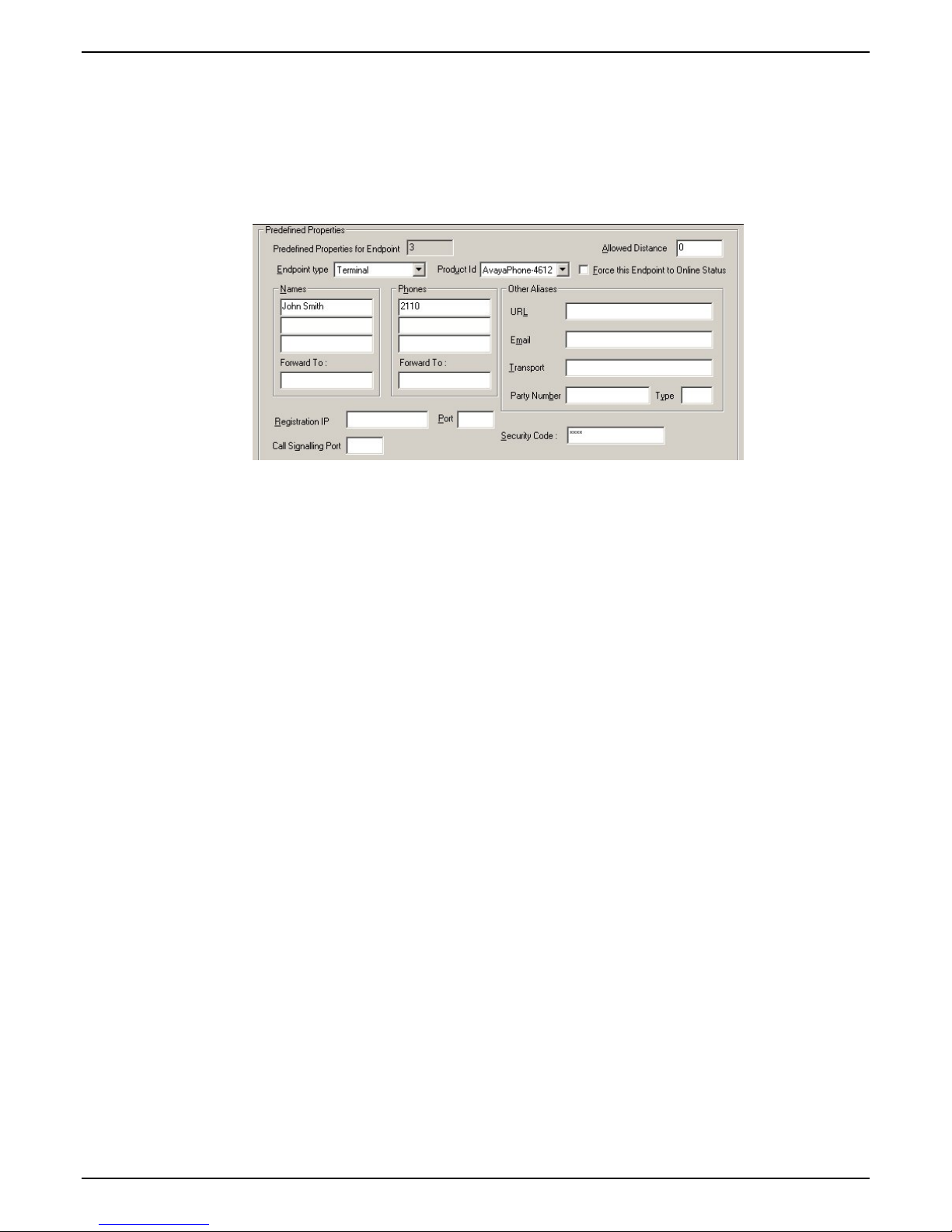
7e. To add an entry for an IP phone, configure Endpoint Type, Product ID, Names, Phones, and
Security code fields as indicated below. Configure Phones and Security Code to match the values
configured for this IP phone in Communication Manager. Leave the other fields blank. One entry
is required for each IP phone located at the same site as this MultiVOIP. Do not create entries for IP
phones located at other sites. They will not be able to register with this MultiVOIP in the event of a
wan link failure. Click OK to save this entry. Repeat the above steps to add additional IP phone
entries. The MVP210, MVP410, and MVP810 support 5,10, or 15 IP phones respectively.
The IP phones must be configured to use DHCP and the DHCP server must be located at the same
site as the MultiVOIP and IP phones. This is the only means by which the IP phones are made aware
of alternate gatekeepers, such as the MultiVOIP gatekeeper when the CM is unavailable due to WAN
link failure.
Refer to the following Avaya documents for instructions on how to configure the DHCP server.
● 4600 Series IP Telephone Lan Administrator’s Guide (Avaya document number 555-233-507).
Read the section titled “DHCP” under “Server Administration”.
● Avaya one-x Deskphone Edition for 9600 Series IP Telephones Administrator’s Guide Release
1.5 (Avaya document number 16-300698). Read the section titled “DHCP and File Server”
under “Server Administration”.
● Avaya one-x Deskphone Value Edition 1600 Series IP Telephones Administrator’s Guide
Release 1.0 (Avaya document number 16-601443). Read the section titled “DHCP Server
Administration”.
Your DHCP server must utilize site-specific options (SSON) #176 (46xx models) and/or #242 (16xx,
96xx models) which are IP Telephone-specific DHCP options specifying information such as TFTP
server and Definity CLAN IP address. The MultiVOIP IP address must be listed at the end of the
string. MCIPADD=xxx.xxx.xxx.xxx,yyy.yyy.yyy.yyy where xxx.xxx.xxx.xxx is one or more IP
addresses used for Definity/CM CLAN IP boards and yyy.yyy.yyy.yyy is the MultiVOIP’s IP
address.
22 Multi-Tech Systems, Inc. Avaya Communication Manager Guide
Page 23
Chapter 2 - Configuration
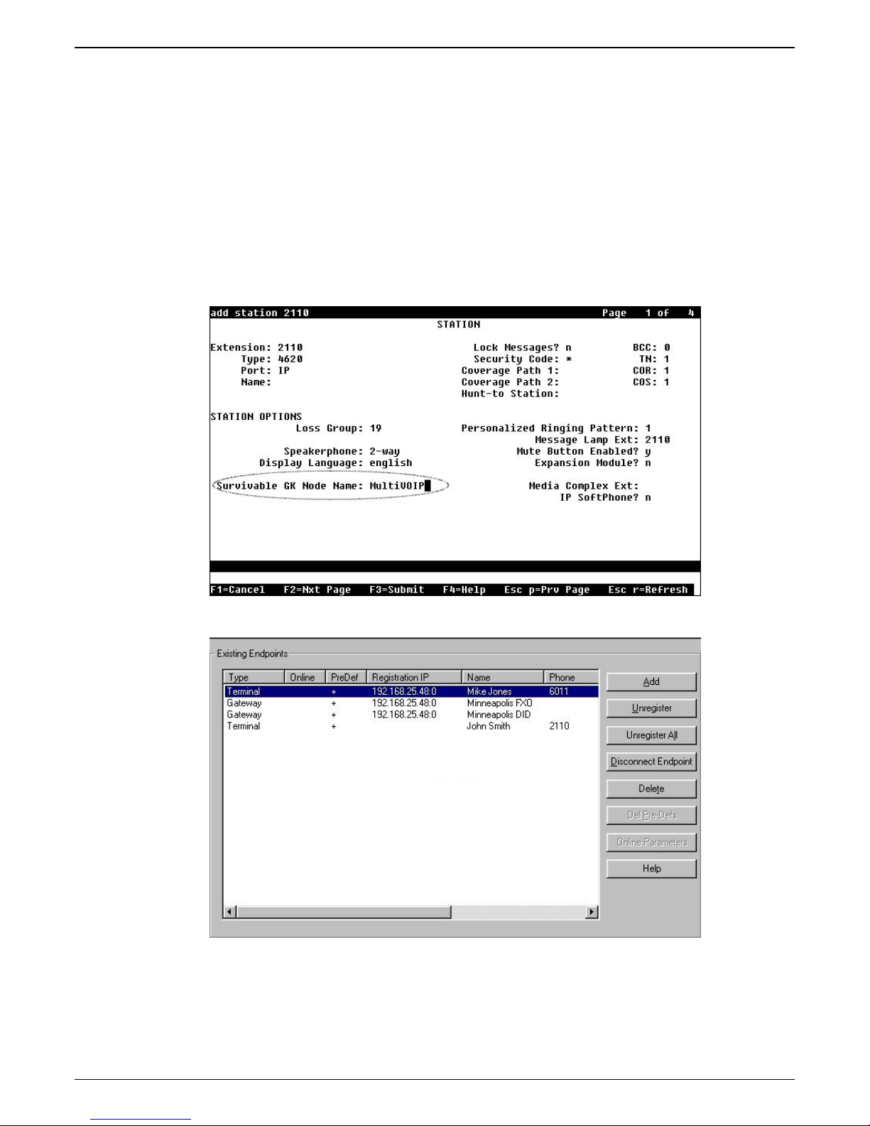
7f. Configure the “Survivable GK Node Name” field with the node name previously given to the
MultiVOIP in the “Node-Names IP” form.
Avaya IP phones running firmware version 2.0 or higher require CM 2.0.1 or higher to work in
survivable mode with the MultiVOIP. When these phones register with the CM, they replace the
list of gatekeepers acquired from the DHCP server (including the MultiVOIP) with a new list of
gatekeepers acquired from CM. This differs from 1.x IP phone firmware where the gatekeeper list
sent to the IP phone from CM was appended to the list of gatekeepers acquired from the DHCP
server. When using CM 2.0.1 or higher, configure the “Survivable GK Node Name” field in the
station form for the IP phone. By doing this, the MultiVOIP will be included in the list of
gatekeepers sent to the IP phone by CM.
Note: IP phone models 4610SW and 4620SW only support 2.0 or higher firmware, therefore these
phones cannot be used with the MultiVOIP unless you are using CM 2.0.1 or higher.
7g. The completed Endpoints screen is shown below:
7h. Click on Save Setup|Save GK Parameters to save the gatekeeper settings.
Multi-Tech Systems, Inc. Avaya Communication Manager Guide 23
Page 24

Chapter 2 – Configuration
8. Create Outbound Phone Book entries to allow the mapping of digit patterns (area codes, 911 calls, etc)
to FXO trunks during gatekeeper survivable mode.
When a survivable call comes in from the IP network to the MultiVOIP gatekeeper, the MultiVOIP will
search through the Outbound Phone book entries in an attempt to find an entry whose Destination
Pattern matches the first few digits of the destination phone number for the call.
If a match is found, the MultiVOIP will manipulate the digits according to the Remove Prefix and Add
Prefix fields of the Outbound Phone book entry. The call with the manipulated digits will be routed to
the predefined gatekeeper endpoint whose Names entry matches the H.323 ID configured in the
Outbound Phone Book entry. This is the normal sequence for calls to FXO trunks.
If there is no match in the Outbound Phone book, the MultiVOIP gatekeeper will try to find a matching
number in the Phones field of one of the MultiVOIP gatekeeper predefined endpoints. This is the
normal sequence for calls to FXS ports or IP phones.
Suppose the MultiVOIP resides in the 763 exchange of the Minneapolis area with its FXO trunk
connected to PSTN lines. This area has an overlayed area code system where calls to 763, 612, 952, and
651 exchanges are all local calls. In this example, we will add Outbound Phone book entries to allow
calls to phone numbers within these exchanges as well as 911 calling for emergencies.
8a. Go to the MultiVOIP’s Phone Book | Phone Book Modify | Outbound Phone Book | List Entries
screen as seen below.
24 Multi-Tech Systems, Inc. Avaya Communication Manager Guide
Page 25

Chapter 2 - Configuration
8b. Click the Add button to add an Outbound Phone Book entry. The Add/Edit Outbound Phone
Book screen will be displayed.
8c. Enter the digit pattern 9763 in the Destination Pattern field. Enter the digit 9 in the Remove Prefix
field Enter a description in the Description field for information purposes only. Enable the Use
Gatekeeper option and enter Minneapolis-FXO in the Gateway H.323 ID field. The Gateway
H.323 ID is essentially a “trunk group name” that matches the Minneapolis-FXO entered in the
Names field of the Gatekeeper Predefined Endpoint for the FXO trunk. Note, If your analog trunk
line requires that all outgoing calls must dial a “9” or some other access code as part of a COCentrex service, you would enter this in the Add Prefix field. Leave the Total Digits and Q.931
Port Number fields set to 0. Leave all other fields blank. Click OK to accept the changes.
Multi-Tech Systems, Inc. Avaya Communication Manager Guide 25
Page 26

Chapter 2 – Configuration
8d. Go to the MultiVOIP’s Phone Book | Phone Book Modify | Outbound Phone Book | List Entries
screen and click the Add button to add another Outbound Phone Book entry for the 612 area code.
Enter the digit pattern of 9612 in the Destination Pattern field. Enter the digit 9 in the Remove
Prefix field.
8e. Add additional Outbound Phone Book entries for calls to the 651 and 952 exchanges as indicated in
the screens below:
26 Multi-Tech Systems, Inc. Avaya Communication Manager Guide
Page 27

Chapter 2 - Configuration
8f. Add an Outbound Phone Book entry to handle the routing of 911 emergency calls to the FXO trunk.
Since 911 must be dialed out the FXO trunk, leave the Remove Prefix field blank.
Multi-Tech Systems, Inc. Avaya Communication Manager Guide 27
Page 28

Chapter 2 – Configuration
8g. The completed Outbound Phone book now includes the entries added in the earlier steps.
Note: For gatekeeper survivability mode, the Inbound Phone book is not used.
8h. Click on Save Setup | Save and Reboot to save the Outbound Phone Book entries.
9. Dialing examples for gatekeeper survivability mode.
9a. Gatekeeper Survivability dialing example #1: A local station to local IP phone call.
The station at FXS port #1 (6011) goes off hook and receives the survivable dial tone from the
MultiVOIP gateway. The client then proceeds to dial 2110.
The MultiVOIP gatekeeper searches the Outbound Phone book for a match to 2110. There is no
match.
The MultiVOIP gatekeeper searches the Phones fields of the Predefined Endpoints and finds a
match for 2110.
The MultiVOIP gatekeeper routes the call to the IP phone registered with the phone number 2110.
When IP phone 2110 answers, the call is completed.
9b. Gatekeeper Survivability dialing example #2: IP phone 2110 dials outward on the local analog
trunk to gain access to the local central office.
IP phone 2110 goes off hook and receives survivable dial tone from the MultiVOIP gatekeeper. The
client then proceeds to dial 97637174321.
The MultiVOIP gatekeeper searches the Outbound Phone book for a match to 97637174321. It finds
a match with Destination Pattern 9763 and Gateway H.323 ID = Minneapolis-FXO. The 9 is
removed and the remaining digits 7637174321 remain.
The MultiVOIP gatekeeper searches the Predefined Endpoints for an entry with Minneapolis-FXO
in the Names field. It finds a match.
The call with digits 7637174321 is routed to the FXO predefined endpoint registered with Name =
Minneapolis-FXO.
The FXO trunk port activates its tip/ring loop-start interface and the digit string “7637174321” is
dialed out towards the network.
When the called party of 7637174321 answers, the call is completed.
28 Multi-Tech Systems, Inc. Avaya Communication Manager Guide
Page 29

Chapter 2 - Configuration
9c. Gatekeeper Survivability dialing example #3: Incoming Central Office call to station 6011. In this
case, the Autocall feature has been enabled in the Voice/Fax screen of the MultiVOIP for the FXO
trunk channels. The Autocall Phone Number field has been set to 6011.
A call from the Central Office line rings in to the MultiVOIP’s FXO trunk.
The MultiVOIP goes off hook on its FXO tip/ring loop-start interface.
The MultiVOIP automatically place a call to 6011 which has been enabled for autocall in the
Voice/Fax screen for the FXO channel.
The MultiVOIP gatekeeper searches the Outbound Phone book for a match to 6011. There is no
match.
The MultiVOIP gatekeeper searches the Phones fields of the Predefined Endpoints and finds a
match for 6011.
The MultiVOIP gatekeeper routes the call to the FXS station port registered with the phone number
6011. When 6011 answers, the call is completed.
Note: If Autocall was not enabled for the FXO port, the incoming caller would have been presented
with survivable dial tone from the MultiVOIP gateway. At this point they could manually dial a
phone number to complete the call.
9d. Gatekeeper survivability dialing example number 4: Incoming central office DID call to IP phone
2110. The central office DID line seizes the MultiVOIP DID trunk and dials 2110.
The MultiVOIP gatekeeper searches the Outbound phone book for a match to 2110. There is no
match.
The MultiVOIP gatekeeper searches the Phones fields of the predefined Endpoints and finds a
match for 2110.
The MultiVOIP gatekeeper routes the call to the IP phone registered with the phone number 2110. When IP
phone 2110 answers, the call is completed.
Multi-Tech Systems, Inc. Avaya Communication Manager Guide 29
Page 30

Chapter 2 – Configuration
Regional Parameters screen
The main distinguishing feature of the Regional Parameters screen for Avaya Communication Manager
MultiVOIPs is the addition of the survivability dial tone.
1. Set the Survivability Tone in the Configuration|Regional Parameters screen.
2. The Regional Parameters screen will appear. For the country selected, the standard set of frequency
pairs will be listed for dial tone, busy tone, ‘unobtainable’ tone (fast busy or trunk busy), and ring
tone.
3. In each field, enter the values that fit your particular system. For most applications, it should be
sufficient to select the appropriate country/region and leave the settings at their default values.
The Regional Parameters fields are described in the table below.
“Regional Parameter” Definitions
Field Name Values Description
Country/
Region
Type column
Frequency 1 freq. in Hertz Lower frequency of pair.
Frequency 2 freq. in Hertz
Gain 1
Australia, Central America,
Chile, Europe, France,
USA, Japan, UK, Custom
Note:
“Survivability” tone
indicates a special type of
call-routing redundancy &
applies to Comm Mgr
VOIP units only.
dial tone, ring tone,
busy tone, unobtainable
tone (fast busy),
survivability tone,
re-order tone
gain in dB
+3dB to –31dB
and “mute” setting
Name of a country or region that uses a certain set of tone pairs
for dial tone, ring tone, busy tone, and ‘unobtainable’ tone (fast
busy tone), survivability tone (tone heard briefly, 2 seconds,
after going offhook denoting survivable mode of VOIP unit)
and re-order tone (a tone pattern indicating the need for the
user to hang up the phone). In some cases, the tone-pair scheme
denoted by a country name may also be used outside of that
country. The “Custom” option (button) assures that any tonepairing scheme worldwide can be accommodated.
Type of telephony tone-pair for which frequency, gain, and
cadence are being presented.
Higher frequency of pair.
Amplification factor of lower frequency of pair.
This applies to the dial, ring, busy and ‘unobtainable’ tones that
the MultiVOIP outputs as audio to the FXS, FXS, or E&M port.
Default: -16dB
30 Multi-Tech Systems, Inc. Avaya Communication Manager Guide
Page 31

Chapter 2 - Configuration
“Regional Parameter” Definitions Continued
Field Name Values Description
Gain 2
Cadence
(msec)
On/Off
Custom
(button)
gain in dB
+3dB to –31dB
and “mute” setting
n/n/n/n
four integer time values in
milli-seconds; zero value
for dial-tone indicates
continuous tone
--
Amplification factor of higher frequency of pair.
This applies to the dial, ring, busy, and ‘unobtainable’ (fast
busy) tones that the MultiVOIP outputs as audio to the FXS,
FXO, or E&M port. Default: -16dB
On/off pattern of tone durations used to denote phone ringing,
phone busy, connection unobtainable (fast busy), dial tone (“0”
indicates continuous tone), survivability, and re-order. Default
values differ for different countries/regions. Although most
cadences have only two parts (an “on” duration and an “off”
duration), some telephony cadences have four parts. Most
cadences, then, are expressed as two iterations of a two-part
sequence. Although this is redundant, it is necessary to allow
for expression of 4-part cadences.
Click on the “Custom” button to bring up the Custom Tone
Pair Settings screen. (The “Custom” button is active only when
“Custom” is selected in the Country/Region field.) This screen
allows the user to specify tone pair attributes that are not found
in any of the standard national/regional telephony toning
schemes.
4. Set Custom Tones and Cadences (optional). . The Regional Parameters dialog box has a secondary
dialog box that allows you to customize DTMF tone pairs to create unique ring-tones, dial-tones, busytones or “unobtainable” tones (fast busy signal) or “re-order” tones (telling the user that she must hang
up an off-hook phone) or “survivability” tones (an indication of call-routing redundancy in
Communication Manager systems only) for your system. Regional Parameters can only be adjusted to
change tones played on FXS or FXO ports. Tones for IP phones are fixed and cannot be changed.
This screen allows the user to specify tone-pair attributes that are not found in any of the standard
national/regional telephony toning schemes. To access this customization feature, click on the Custom
button on the Regional Parameters screen. (The “Custom” button is active only when “Custom” is
selected in the Country/Region field.)
Multi-Tech Systems, Inc. Avaya Communication Manager Guide 31
Page 32

Chapter 2 – Configuration
The Custom Tone-Pair Settings fields are described in the table below.
Custom Tone-Pair Settings Definitions
Field Name Values Description
Tone Pair
TONE PAIR VALUES
Frequency 1 frequency in Hertz Frequency of lower tone of pair.
Frequency 2 frequency in Hertz Frequency of higher tone of pair.
Gain 1 gain in dB
Gain 2 gain in dB
Cadence 1 integer time value in
dial tone, busy tone,
ring tone, ‘unobtainable’
tone, survivability tone,
re-order tone
+3dB to –31dB
and “mute” setting
+3dB to –31dB
and “mute” setting
milli-seconds; zero
value for dial-tone
indicates continuous
tone
Identifies the type of telephony signaling tone for which
frequencies are being specified.
About Defaults: US telephony values are used as defaults on
this screen. However, since this dialog box is provided to allow
custom tone-pair settings, default values are essentially
irrelevant.
This outbound tone pair enters the MultiVOIP at the input port.
This outbound tone pair enters the MultiVOIP at the input port.
Amplification factor of lower frequency of pair. This figure
describes amplification that the MultiVOIP applies to outbound
tones entering the MultiVOIP at
the input port. Default = -16dB
Amplification factor of higher frequency of pair. This figure
describes amplification that the MultiVOIP applies to outbound
tones entering the MultiVOIP at
the input port. Default = -16dB
On/off pattern of tone durations used to denote phone ringing,
phone busy, dial tone (“0” indicates continuous tone)
survivability and re-order. Cadence 1 is duration of first period
of tone being “on” in the cadence of the telephony signal (which
could be ring-tone, busy-tone, unobtainable-tone, or dial-tone).
Cadence 2 duration in milliseconds Cadence 2 is duration of first “off” period in signaling cadence.
Cadence 3 duration in milliseconds Cadence 3 is duration of second “on” period in signaling
cadence.
Cadence 4 duration in milliseconds
Cadence 4 is duration of second “off” period in the signaling
cadence, after which the 4-part cadence pattern of the telephony
signal repeats.
32 Multi-Tech Systems, Inc. Avaya Communication Manager Guide
Page 33

Chapter 3 – Related MultiVOIP Setup Parameters
Chapter 3 – Related MultiVOIP Setup Parameters
For your convenience, the Communication Manager Settings, MultiVOIP Voice/Fax, Interface, and Gatekeeper
parameters are detailed in this section.
Communication Manager Settings
In the Communication Manager Settings screen, if the “Register with Communication Manager Gatekeeper
option is selected, then many of the parameters must assume default values and those will be grayed on the
screen.
The Communication Manager Parameter fields are described in the table below.
Communication Manager Parameter Definitions
Field Name Values Description
Select Channel Channel n Denotes the VOIP channel to which settings in the current screen
“Interface Type
is …”
FXS Loop Start;
FXO; DID
Multi-Tech Systems, Inc. Avaya Communication Manager Guide 33
apply.
Indicates the telephony interface used on the selected VOIP channel.
Page 34

Chapter 3 – Related MultiVOIP Setup Parameters
ying
y
y
g
g
g
Communication Manager Parameter Definitions Continued
Field Name Values Description
Q.931 Parameters
Use Fast Start Y/N Enables the H.323 Fast Start procedure. If “Register with
is enabled, this field defaults to
Call Signaling
Port
Delay Before
Dial
Gatekeeper
Name
Gateway
Prefix
Gateway H.323
ID
Phone
Number/
Extension
Communication Manager Gatekeeper”
“N” and cannot be changed.
port number This value must be unique for each of the MultiVOIP’s FXS ports.
This value must be the same for all of the MultiVOIP unit’s
FXO/DID ports that are managed by CM.
in milliseconds Applicable to FXO ports only. It indicates the amount of delay that
will be introduced before a dialed sequence is sent.
GateKeeper RAS Parameters
alpha-numeric string Optional. The name of the GateKeeper with which this MultiVOIP is
tr
to register.
If “Register with Communication Manager Gatekeeper” is enabled, this
field is not used. This number becomes registered with the
GateKeeper. Call requests sent to the gatekeeper and preceded by
this prefix will be routed to the VOIP gateway.
The H.323 ID is used to register FXO trunks with the MultiVOIP
GateKeeper.
numeric
This phone number (PBX extension) must match the extension
configured on the Communication Manager “station” form (dialog
box). It is only relevant for the MultiVOIP’s FXS channels.
Security Code alpha-numeric This field value must match the security code configured on the
Communication Manager “station” form (dialog box). It is only
relevant for the MultiVOIP’s FXS channels.
Buttons
Default Applies default values to all fields in the Communication Manager
Parameters screen.
Unregister Allows you to unregister the registered station or trunk with respect
to the Communication Manager Gatekeeper. This command has an
immediate effect. This is a ver
Register Allows you to register the unregistered station or trunk with respect
to the Communication Manager Gatekeeper. This command has an
immediate effect. This is a ver
Columns
GateKeeper IP
Address
RAS Port Typically this is 1719.
GateKeeper
Name
Primary
[
atekeeper]
Alternate GK 1 It is optional for the system to have a PBX that serves as a first
Alternate GK 2 It is optional for the system to have a PBX that servers as a second
The IP address of the Communication Manager Gatekeeper.
This field must be left blank
Rows
One PBX in the system must serve as the primary gatekeeper.
alternate
alternate
atekeeper.
atekeeper.
useful diagnostic command.
useful diagnostic command.
34 Multi-Tech Systems, Inc. Avaya Communication Manager Guide
Page 35

Chapter 3 – Related MultiVOIP Setup Parameters
)
g
g
Communication Manager Parameter Definitions (cont’d)
Field Name Values Description
RAS Time to
Live
Enable
Survivability
Mode
Switching
Time Interval
Q.931
Multiplexing
(Mux)
H.245
Tunneling
(Tun)
Parallel H.245
(FS + Tun)
Annex –E (AE) Y/N
Numeric
(in seconds)
Y/N Enable/disable MultiVOIP’s Gateway Survivable mode wherein
numeric
(in seconds)
Y/N Signaling for multiple phone calls can be carried on a single port
Y/N H.245 messages are encapsulated within the Q.931 call-signaling
Y/N
The MultiVOIP sends this value to CM in the Registration Request
(RRQ). However, the MultiVOIP will send “Keepalive” RRQs based
on the TTL received from CM
MultiVOIP manages its own IP traffic using its inbound and
outbound phonebooks in the event of failure of the primary, alternate
#1 and #2
When MultiVOIP is in “gateway” survivable mode meaning the
Communication Manager gatekeeper to which it is registered failed
(along with any alternate gatekeepers providing redundancy), the
MultiVOIP manages IP phone traffic with its own phonebooks. It
will seek to return to being controlled by the Communication
Manager gatekeeper. The Switching Time Interval determines how
often it will seek to restore its registration with the primary
Communication Mana
H.323 Version 4 Parameters
rather than opening a separate signaling port for each call. This
conserves bandwidth resources.
If
“Register with Communication Manager Gatekeeper” is enabled, this
field defaults to “Y” for FXO/DID ports and to “N” for FXS ports
and it cannot be changed.
channel. Among other things, the H.245 messages let the two
endpoints tell each other what their technical capabilities are and
determine who, during the call, will be the client and who the server.
Tunneling is the process of transmitting these H.245 messages
through the Q.931 channel. The same TCP/IP socket (or logical port)
already being used for the Call Signaling Channel is then also used
by the H.245 Control Channel. This encapsulation reduces the
number of logical ports (sockets) needed and reduces call setup time.
If “Register with Communication Manager Gatekeeper” is enabled, this
field defaults to “Y” for FXS and FXO ports and cannot be changed.
H.323 Version 4 Parameters
FS (Fast Start or Fast Connect) is a Q.931 feature of H.323v2 to
hasten call setup as well as ‘pre-opening’ the media channel before
the CONNECT message is sent. This pre-opening is a requirement
for certain billing activities. Under Parallel H.245 FS + Tun, this Fast
Connect feature can operate simultaneously with H.245 Tunneling
(see description above).
“Register with Communication Manager Gatekeeper” is enabled, this
If
field defaults to “N” for FXS and FXO ports and cannot be changed.
Multiplexed UDP call signaling transport. Annex E is helpful for
high-volumeVOIP system endpoints. Gateways with lesser volume
can afford to use TCP to establish calls. However, for larger volume
endpoints, the call setup times and system resource usage under
TCP can become problematic. Annex E allows endpoints to perform
call- signaling functions under the UDP protocol, which involves
substantially streamlined overhead. (This feature should not be
used on the public Internet because of potential problems with
security and bandwidth usage.)
“Register with Communication Manager Gatekeeper” is enabled, this
If
field defaults to “N” for FXS and FXO ports and cannot be changed.
atekeepers (if alternates are present).
during Registration Confirm (RCF
er gatekeeper.
Multi-Tech Systems, Inc. Avaya Communication Manager Guide 35
Page 36

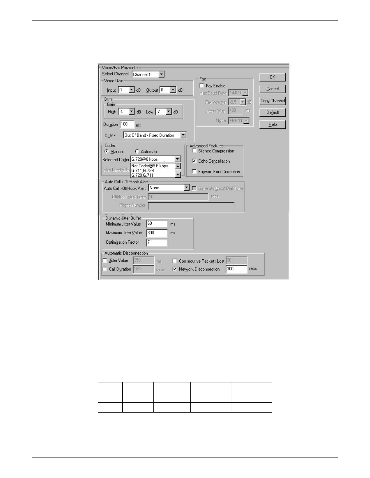
Voice/Fax Parameters
In each field, enter the values that fit your particular network.
Chapter 3 – Related MultiVOIP Setup Parameters
36 Multi-Tech Systems, Inc. Avaya Communication Manager Guide
Page 37

Chapter 3 – Related MultiVOIP Setup Parameters
Note that Voice/FAX parameters are applied on a channel-by-channel basis. However, once you have
established a set of Voice/FAX parameters for a particular channel, you can apply this entire set of
Voice/FAX parameters to another channel by using the Copy Channel button and its dialog box. To copy
a set of Voice/FAX parameters to all channels, select “Copy to All” and click Copy.
The Voice/FAX Parameters fields are described in the tables below.
Voice/Fax Parameter Definitions
Field Name Values Description
Default --
When this button is clicked, all Voice/FAX parameters
are set to their default values.
Select
Channel
Copy
Channel
1-2 (210) 1-4 (410)
1-8 (810)
--
Channel to be configured is selected here.
Copies the Voice/FAX attributes of one channel to
another channel. Attributes can be copied to multiple
channels or all channels at once.
Voice Gain -- Signal amplification (or attenuation) in dB.
Input Gain +31dB to –31dB
Modifies audio level entering voice channel before it is
sent over the network to the remote VOIP. The default &
recommended value is 0 dB.
Output Gain +31dB to –31dB
Modifies audio level being output to the device attached
to the voice channel. The default and recommended
value is 0 dB.
Multi-Tech Systems, Inc. Avaya Communication Manager Guide 37
Page 38

Voice/Fax Parameter Definitions Continued
Field Name Values Description
DTMF Parameters
DTMF Gain --
The DTMF Gain (Dual Tone Multi-Frequency) controls
the volume level of the DTMF tones sent out for Touch-
Tone dialing.
DTMF Gain,
High Tones
DTMF Gain,
Low Tones
Duration
(DTMF)
DTMF
In/Out of
Band
+3dB to -31dB &
“mute”
+3dB to -31dB &
“mute”
60 – 3000 ms
Out of Band, or Inband
FAX Parameters
Default value: -4 dB. Not to be changed except under
supervision of MultiTech’s Technical Support.
Default value: -7 dB. Not to be changed except under
supervision of MultiTech’s Technical Support.
When DTMF: Out of Band is selected, this setting determines
how long each DTMF digit ‘sounds’ or is held. Default = 100
ms.
When DTMF Out of Band is selected, the MultiVOIP detects
DTMF tones at its input and regenerates them at its output.
When DTMF Inband is selected, the DTMF digits are passed
through the MultiVOIP unit as they are received.
Fax Enable Y/N Enables or disables fax capability for a particular channel.
Max Baud
Rate
(Fax)
Fax Volume
(
Default =
-9.5 dB
)
Jitter Value
(Fax)
Mode (Fax) FRF 11; T.38
2400, 4800, 7200, 9600,
12000, 14400 bps
-18.5 dB
to –3.5 dB
Default =
400 ms
Set to match baud rate of fax machine connected to channel
(see Fax machine’s user manual). For CM managed fax calls it
is recommended to use 9600.
Default = 14400 bps.
Controls output level of fax tones. To be changed only under
the direction of Multi-Tech’s Technical Support.
Defines the inter-arrival packet deviation (in milliseconds) for
the fax transmission. A higher value will increase the delay,
allowing a higher percentage of packets to be reassembled. A
lower value will decrease the delay allowing fewer packets to
be reassembled.
FRF11 is frame-relay FAX standard using these coders: G.711, G.728,
G.729, G.723.1.
T.38 is an ITU-T standard for storing and forwarding FAXes
via email using X.25 packets. It uses T.30 fax standards and
includes special provisions to preclude FAX timeouts during
IP transmissions. Must use T.38 when faxing to/from CM.
Note: When the MultiVOIP stops receiving T.38 packets, it will
wait ten seconds before switching to voice mode.
Coder Parameters
Coder Manual or
Auto-matic
Determines whether selection of coder is manual or
automatic. Must be set to manual for CM managed calls.
When Automatic is selected, the local and remote voice
channels will negotiate the voice coder to be used by
selecting the highest bandwidth coder supported by
both sides without exceeding the Max Bandwidth
setting. G.723, G.729, or G.711 are negotiated.
Chapter 3 – Related MultiVOIP Setup Parameters
38 Multi-Tech Systems, Inc. Avaya Communication Manager Guide
Page 39

Chapter 3 – Related MultiVOIP Setup Parameters
Voice/Fax Parameter Definitions Continued
Field Name Values Description
Coder Parameters (cont’d)
Selected
Coder
G.711 a/u law 64 kbps;
G.726, @ 16/24/32/40
kbps;
G.727, @ nine bps rates;
G.723.1 @ 5.3 kbps,
6.3 kbps;
G.729, 8kbps;
Net Coder @ 6.4, 7.2, 8,
8.8, 9.6 kbps
G.711/G.729
Select from a range of coders with specific bandwidths.
The higher the bps rate, the more bandwidth is used.
The channel that you are calling must have the same
voice coder selected.
Default = G.723.1 @ 6.3 kbps, as required for H.323.
Here 64K of digital voice are compressed to 6.3K,
allowing several simultaneous conversations over the
same bandwidth that would otherwise carry only one.
To make selections from the Selected Coder drop-down
list, the Manual option must be enabled.
G.729/G.711
Max
bandwidth
(coder)
11 – 128 kbps
This drop-down list enables you to select the maximum
bandwidth allowed for this channel. The Max
Bandwidth drop-down list is enabled only if the Coder
is set to Automatic.
If coder is to be selected automatically (“Auto” setting),
then enter a value for maximum bandwidth.
Advanced Features
Silence
Compression
Echo
Cancellation
Forward
Error
Correction
Y/N
Y/N Determines whether echo cancellation is enabled (checked) for
Y/N Determines whether forward error correction is enabled
Determines whether silence compression is enabled (checked)
for this voice channel.
With Silence Compression enabled, the MultiVOIP will not
transmit voice packets when silence is detected, thereby
reducing the amount of network bandwidth that is being used
by the voice channel.
Default = off.
this voice channel.
Echo Cancellation removes echo and improves sound quality.
Default = on.
(checked) for this voice channel.
Forward Error Correction enables some of the voice packets
that were corrupted or lost to be recovered. FEC adds an
additional 50% overhead to the total network bandwidth
consumed by the voice channel. Default = Off
Multi-Tech Systems, Inc. Avaya Communication Manager Guide 39
Page 40

Field
Values Description
Name
AutoCall/Offhook
Alert Parameters
Chapter 3 – Related MultiVOIP Setup Parameters
Voice/Fax Parameter Definitions Continued
Auto
Call /
Offhook
Alert
Generate
Local
Dial
Tone
AutoCall,
Offhook
Alert
The AutoCall option enables the local MultiVOIP to place a call without the user
having to dial a number. As soon as you access the local MultiVOIP voice/fax
channel, the MultiVOIP immediately connects to the remote endpoint identified
in the Phone Number box of this option.
If the “Pass Through Enable” field is checked in the Interface Parameters screen,
AutoCall must be used.
The Offhook Alert option applies only to FXS channels.
The Offhook Alert option works like this: if a phone goes offhook and no
number is dialed within a specific period of time (as set in the Offhook Alert
Timer field), then that phone will automatically dial the Alert phone number for
the voip channel. (The Alert phone number must be set in the Voice/Fax
Parameters | Phone Number field). One use of this feature would be for
emergency use where a user goes off hook but does not dial, possibly indicating
a crisis situation. The Offhook Alert feature uses the Intercept Tone, as listed in
the Regional Parameters screen. This tone will be output on the phone that was
taken off hook but that did not dial. The other end of the connection will hear
audio from the “crisis” end as it would during a normal phone call.
Both functions apply on a channel-by-channel basis. It would not be appropriate
for either of these functions to be applied to a channel that serves in a pool of
available channels for general phone traffic.
Y/N Used for AutoCall only. If selected, dial tone will be generated locally while the
call is being established between gateways. The capability to generate dial tone
locally would be particularly useful when there is a lengthy network delay.
Offhook
Alert
0 – 3000
seconds
The length of time that must elapse before the offhook alert is triggered and a call
is automatically made to the phone number listed in the Phone Number field.
Timer
Phone
-- Phone number used for Auto Call function or Offhook Alert Timer function.
Number
Dynamic Jitter
Dynamic
Jitter
Buffer
Dynamic Jitter defines a minimum and a maximum jitter value for voice
communications. When receiving voice packets from a remote
MultiVOIP, varying delays between packets may occur due to network
traffic problems. This is called Jitter. To compensate, the MultiVOIP uses
a Dynamic Jitter Buffer. The Jitter Buffer enables the MultiVOIP to wait
for delayed voice packets by automatically adjusting the length of the
Jitter Buffer between configurable minimum and maximum values. An
Optimization Factor adjustment controls how quickly the length of the
Jitter Buffer is increased when jitter increases on the network. The length
of the jitter buffer directly effects the voice delay between
gateways.
MultiVOIP
40 Multi-Tech Systems, Inc. Avaya Communication Manager Guide
Page 41

Chapter 3 – Related MultiVOIP Setup Parameters
Voice/Fax Parameter Definitions (cont’d)
Field Name Values Description
Dynamic Jitter (cont’d)
Minimum
Jitter Value
60 to 400 ms The minimum dynamic jitter buffer of 60 milliseconds is
the minimum delay that would be acceptable over a low
jitter network.
Default = 150 msec
Maximum
Jitter Value
60 to 400 ms The maximum dynamic jitter buffer of 400 milliseconds is
the maximum delay tolerable over a high jitter network.
Default = 300 msec
Optimization
Factor
0 to 12 The Optimization Factor determines how quickly the
length of the Dynamic Jitter Buffer is changed based on
actural jitter encountered on the network. Selecting the
minimum value of 0 means low voice delay is desired,
but increases the possibility of jitter induced voice quality
problems. Selecting the maximum value of 12 means
highest voice qauality under jitter conditions is desired at
the cost of increased voice delay.
Default = 7.
Auto Disconnect
Automatic
Disconnect-
-- The Automatic Disconnection group provides four
options which can be used singly or in any combination.
ion
Jitter Value 1-65535
milli-seconds
The Jitter Value defines the average inter-arrival packet
deviation (in milliseconds) before the call is automatically
disconnected. The default is 300 milliseconds. A higher
value means voice transmission will be more accepting of
jitter. A lower value is less tolerant of jitter.
Inactive by default. When active, default = 300 ms.
However, value must equal or exceed Dynamic
Minimum Jitter Value.
Call Duration 1-65535 seconds Call Duration defines the maximum length of time (in
seconds) that a call remains connected before the call is
automatically disconnected.
Inactive by default.
When active, default = 180 sec.
This may be too short for most configurations, requiring
upward adjustment.
Consecutive
Packets Lost
1-65535 Consecutive Packets Lost defines the number of
consecutive packets that are lost after which the call is
automatically disconnected.
Inactive by default.
When active, default = 30
Network
Disconnection
1 to 65535 seconds;
Default = 30 sec.
Specifies how long to wait before disconnecting the call
when IP network connectivity with the remote site has
been lost.
Multi-Tech Systems, Inc. Avaya Communication Manager Guide 41
Page 42

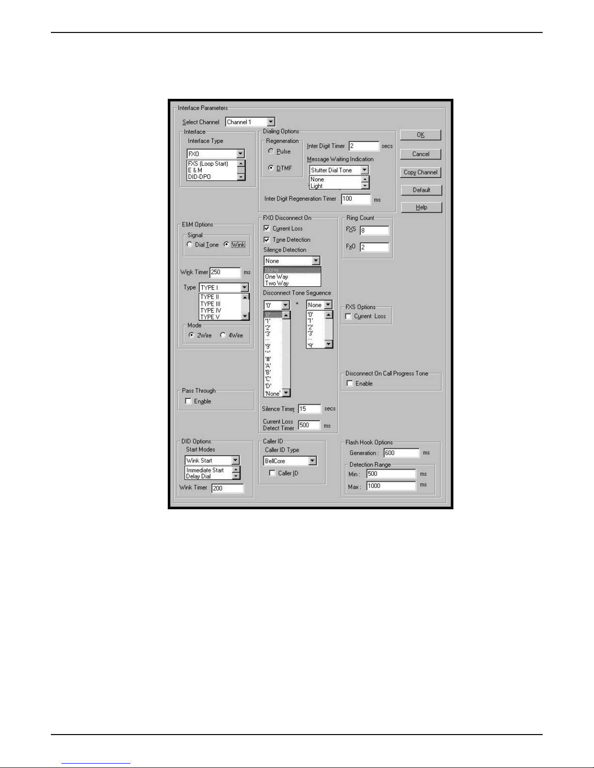
Interface Parameters
In each field, enter the values that fit your particular network.
Chapter 3 – Related MultiVOIP Setup Parameters
42 Multi-Tech Systems, Inc. Avaya Communication Manager Guide
Page 43

Chapter 3 – Related MultiVOIP Setup Parameters
The kinds of parameters for which values must be chosen depend on the type of telephony supervisory
signaling or interface used (FXO, E&M, etc.). We present here the various parameters grouped and
organized by interface type.
Note that Interface parameters are applied on a channel-by-channel basis. However, once you have
established a set of Interface parameters for a particular channel, you can apply this entire set of Voice/FAX
parameters to another channel by using the Copy Channel button and its dialog box. To copy a set of
Interface parameters to all channels, select “Copy to All” and click Copy.
Multi-Tech Systems, Inc. Avaya Communication Manager Guide 43
Page 44

Chapter 3 – Related MultiVOIP Setup Parameters
FXS Loop Start Parameters. The parameters applicable to FXS Loop Start are shown in the figure below
and described in the table that follows.
FXS Loop Start Interface: Parameter Definitions
Field Name Values Description
FXS (Loop
Start)
Dialing Options fields
Inter Digit
Timer
Message
Waiting
Indication
Inter Digit
Regeneration
Time
Ring Count,
FXS
FXS Options,
Current Loss
Y/N Enables FXS Loop Start interface type.
1 - 10 seconds This is the length of time that the MultiVOIP will wait between
digits. When the time expires, the MultiVOIP will place the call.
Default = 2.
-- If “Register with Communication is enabled”, this field enables
message waiting indication on FXS channels. Choices are “Light” or
“Stutter Dial Tone”.
in milliseconds
1-99
Y/N
The length of time between the outputting of DTMF digits.
Default = 100 ms.
Maximum number of rings that the MultiVOIP will issue before
giving up the attempted call.
When enabled, the MultiVOIP will interrupt loop current in the FXS
circuit to initiate a disconnection. This tells the device connected to
the FXS port to hang up. The Multi-VOIP cannot drop the call; the
FXS device must go on hook.
44 Multi-Tech Systems, Inc. Avaya Communication Manager Guide
Page 45

Chapter 3 – Related MultiVOIP Setup Parameters
FXS Loop Start Interface: Parameter Definitions (cont’d)
Field Name Values Description
Flash Hook Options fields
Generation --
Detection
Range
Pass Through
Enable
Caller ID Type Bellcore
Caller ID
enable
Caller ID
enable (cont’d)
for Min. and Max.,
50 - 1500
milliseconds
Y/N
Caller ID fields
Y/N
Y/N
not applicable to FXS interface
For a received flash hook to be regarded as such by the MultiVOIP,
its duration must fall between the minimum and maximum values
given here.
Not used if “Register with Communication Manager” is enabled
The MultiVOIP currently supports only one implementation of Caller
ID. That implementation is Bellcore type 1 with Caller ID placed
between the first and second rings of the call.
Caller ID information is a description of the remote calling party
received by the called party. The description has three parts: name
of caller, phone number of caller, and time of call. The ‘time-of-call’
portion is always generated by the receiving MultiVOIP unit (on FXS
channel) based on its date and time setup.
The forms of the ‘Caller Name’ and ‘Caller Phone Number’ differ
depending on the IP transmission protocol used (H.323, SIP, or SPP)
and upon entries in the phonebook screens of the remote (CID
generating) voip unit. The CID Name and Number appearing on the
phone at the terminating FXS end will come either from a central
office switch (showing a PSTN phone number), or the phonebook of
the remote (CID sending) voip unit.
The Caller ID feature has dependencies on both the telco central office and the MultiVOIP phone book. See
discussion after the FXO Parameters section below.
Multi-Tech Systems, Inc. Avaya Communication Manager Guide 45
Page 46

Chapter 3 – Related MultiVOIP Setup Parameters
FXO Parameters. The parameters applicable to the FXO telephony interface type are shown in the figure
below and described in the table that follows.
FXO Interface: Parameter Definitions
Field Name Values Description
Interface, FXO Y/N Enables FXO functionality
Dialing Options
Regeneration Pulse, DTMF Determines whether digits generated and sent out will be pulse tones
Message
Waiting
Indication
Inter Digit
Regeneration
Time
FXO Disconnect On
Current Loss Y/N Disconnection to be triggered by loss of current. That is, when
Current Loss
Detect Timer
Tone Detection Y/N Disconnection to be triggered by a tone sequence.
50 to 20,000
milliseconds
integer values
(in milliseconds )
-- Not applicable to FXO interface.
or DTMF.
The length of time between the outputting of DTMF digits.
Default = 100 ms.
There are three possible criteria for disconnection under FXO: current
loss, tone detection, and silence detection. Disconnection can be
triggered by more than one of the three criteria.
Current Loss is enabled (“Y”), the MultiVOIP will hang up the call
when it detects a loss of current initiated by the attached device.
The minimum time required for detecting the current loss signal on
the FXO interface. In other words, this is the minimum length of
time the current must be absent to validate ‘current loss’ as a
disconnection criterion. Default = 500 ms.
46 Multi-Tech Systems, Inc. Avaya Communication Manager Guide
Page 47

Chapter 3 – Related MultiVOIP Setup Parameters
FXO Interface: Parameter Definitions (cont’d)
Field Name Values Description
FXO Disconnect On (cont’d)
Disconnect
Tone Sequence
Silence
Detection
Silence Timer
in seconds
Disconnect on
Call Progress
Tone
Ring Count,
FXO
1st tone pair
+
nd
2
tone pair
These are DTMF tone pairs.
Values for first tone pair are:
*, #, 0, 1-9, and A-D.
Values for second tone pair are:
none, 0, 1-9, A-D, *, and #.
The tone pairs 1-9, 0, *, and # are the standard DTMF pairs found on
phone sets. The tone pairs A-D are “extended DTMF” tones, which
are used for various PBX functions.
DTMF Tone Pairs
2
1
4
7
*
High Tones 1209Hz 1336Hz 1447Hz 1633Hz
One-Way or
Two-Way
3
5
6
8
9
0
#
Disconnection to be triggered by silence in one direction only or in
both directions simultaneously.
A
B
C
D
Low Tones
697Hz
770Hz
852Hz
941Hz
integer value Duration of silence required to trigger disconnection.
Y/N Allows call on FXO port to be disconnected when a PBX issues a call-
progress tone denoting that the phone station on the PBX that has
been involved in the call has been hung up.
1-99 Number of rings required before the MultiVOIP answers the
incoming call.
Flash Hook Options fields
Generation 50 - 1500
milliseconds
Length of flash hook that will be generated and sent out when the
remote end initiates a flash hook and it is regenerated locally.
Default = 600 ms.
Detection
-- Not applicable to FXO.
Range
Caller ID fields
Caller ID Type Bellcore
The MultiVOIP currently supports only one implementation of Caller
ID. That implementation is Bellcore type 1 with caller ID placed
between the first and second rings of the call.
Caller ID
enable
Y/N
Caller ID information is a description of the remote calling party
received by the called party. The description has three parts: name
of caller, phone number of caller, and time of call. The ‘time-of-call’
portion is always generated by the receiving MultiVOIP unit (on FXS
channel) based on its date and time setup. The forms of the ‘Caller
Name’ and ‘Caller Phone Number’ differ depending on the IP
transmission protocol used (H.323, SIP, or SPP) and upon entries in
the phonebook screens of the remote (CID generating) voip unit. The
CID Name and Number appearing on the phone at the terminating
FXS end will come either from a central office switch (showing a
PSTN phone number), or the phonebook of the remote (CID sending)
voip unit.
Multi-Tech Systems, Inc. Avaya Communication Manager Guide 47
Page 48

Chapter 3 – Related MultiVOIP Setup Parameters
The Caller ID feature has dependencies on both the telco central office and the MultiVOIP phone book. See
discussion below.
Call is received
here.
xxxyyyzzzz
J.Q. Public
Display shows:
FXS
CID
Terminating
VoIP
Clock:
5-31,
1:42pm
CID Number: 763-555-8794
CID Name: Melvin Jones
Time Stamp: Date: 05/31
Time:1:42pm
In x.06 release, when SIP protocol is used,
*
CID Name field will duplicate value in
CID Number field.
CID Flow
IP
Network
H.323 or SPP
Protocol
Call originates here
CID
Generating
VoIP
FXO
Central Office
with
standard telephony
Caller ID service
at 1:42pm, May 31.
xxxyyyzzzz
J.Q. Public
phone of:
*
Melvin Jones
763-555-8794
Figure 1: Voip Caller ID Case #1 – Call, through telco central office with standard CID, enters
voip system
Call is received
here.
xxxyyyzzzz
J.Q. Public
Display shows:
FXS
CID
Terminating
VoIP
Clock:
7/10, 4:19pm
CID Number: 423
CID Name: Anoka-Whse-VP3
Time Stamp: Date: 7/10
Time: 4:19pm
In x.06 release, when SIP protocol is used,
*
CID Name field will duplicate value in
CID Number field.
CID Flow
IP
Network
H.323 Protocol
CID
Ch1
Generating
VoIP
FXO
Ch2
Ch3
Ch4
*
Phone Book Configuration
Gateway Name:
Q.931 Parameters
Gatekeeper RAS Parameters
Anoka-Whse-VP3
Call originates here
Central Office
without
standard telephony
Caller ID service
at 4:19pm, July 10.
xxxyyyzzzz
J.Q. Public
phone of:
Wilda Jameson
763-555-4071
Inbound Phone Book
Remove Prefix Add Prefix Forward/Addr
423
748
{Channel 2}
Figure 2: Voip Caller ID Case #2 – Call, through telco central office without standard CID,
enters H.323 voip system
Call is received
here.
xxxy yyzzzz
J.Q. P u blic
Display shows:
FXS
Termin ating
VoIP
Clock:
15: 26, 5- 31
CID Number: 423
CID Name: Shipping Dept
Time Stamp: Date: 0927
Time: 174 7
... if “Descriptio n” field in Add/Edit
Inbou nd P hon e Bo ok is used
OR
CID Number: 423
CID Name: Anoka-Whse-VP3
Time Stamp: Date: 0927
Time: 174 7
... if “Descriptio n” in Add/Edit
Inbou nd Phon e Bo ok is bla n k
CID Flow
IP
Network
SPP Protocol
Ch1
Generating
FXO
VoI P
Ch2
Ch3
Ch4
Add/Edit Inbound Phone Book
Channel Numbe r:
Use as de fault e ntry
Remove Prefix:
Add Prefix :
Descript ion:
standard telephony
Caller ID service
Call originates here
Central Office
without
at 5:47pm, Sept 27.
xxxyy yzzzz
J.Q. P u blic
phone of:
Henry Brampton
763-555-4077
Inbound Phone Book
Remove Prefix Add Prefix Forward/Addr
423
748
Phone Book Configuration
Gatew ay Name:
Q.931 Parameters
Gatekeeper RAS Parameters
Channel 2
Ship ping Dept
Anoka-Whse-VP3
{Channel 2}
Figure 3: Voip Caller ID Case #3 – Call, through telco central office without standard CID,
enters SPP voip system
48 Multi-Tech Systems, Inc. Avaya Communication Manager Guide
Page 49

Chapter 3 – Related MultiVOIP Setup Parameters
Call is received
here.
xxxyyyzzzz
J.Q. Public
Display shows:
FXS
CID
Terminating
VoIP
Clock:
10/03, 4:51pm
CID Number: 423
CID Name: Anoka-Whse-VP3
Time Stamp: Date: 10/03
Time: 4:51pm
In x.06 release, when SIP protocol is used,
*
CID Name field will duplicate value in
CID Number field.
CID Flow
IP
Network
H.323 Protocol
CID
FXS
Ch1
Generating
401
VoIP
Ch2
402
Ch3
403
Ch4
*
404
Phone Book Configuration
Gateway Name:
Q.931 Parameters
Gatekeeper RAS Parameters
Anoka-Whse-VP3
Call originates here
at 4:51pm, Oct 3.
xxxyyyzzzz
J.Q. Public
phone of:
Nigel Thurston
763-555-9401
Inbound Phone Book
Remove Prefix Add Prefix Forward/Addr
423
748
{Channel 2}
Figure 4: Voip Caller ID Case #4 – Remote FXS call on H.323 voip system
Call is received
here.
xxxyyyzzzz
J.Q. Public
Display shows:
FXS
CID
Terminating
VoIP
Clock:
11/15, 6:17pm
CID Number: 423
CID Name: Anoka-Whse-VP3
Time Stamp: Date: 11/15
Time: 6:17pm
In x.06 release, when SIP protocol is used,
*
CID Name field will duplicate value in
CID Number field.
CID Flow
IP
Network
H.323 Protocol
CID
Ch1
Generating
VoIP
DID
Ch2
Ch3
Ch4
*
Phone Book Configuration
Gateway Name:
Q.931 Parameters
Gatekeeper RAS Parameters
Anoka-Whse-VP3
Call originates here
Central Office
without
standard telephony
Caller ID service
at 6:17pm, Nov 15.
xxxyyyzzzz
J.Q. Public
phone of:
Edwin Smith
763-743-5873
Inbound Phone Book
Remove Prefix Add Prefix Forward/Addr
423
748
{Channel 2}
Figure 5: Voip Caller ID Case #5 – Call through telco central office without standard CID enters
DID channel in H.323 voip system
E&M Parameters. E&M is not supported if “Register with Communication Manager” is enabled.
DID Parameters. The parameters applicable to the Direct Inward Dial (DID) telephony interface type are
shown in the figure below and described in the table that follows. The DID interface allows one phone line
to direct incoming calls to any one of several extensions without a switchboard operator. Of course, one
DID line can handle only one call at a time. The parameters described here pertain to the customerpremises side of the DID connection (DID-DPO, dial-pulse originating); the network side of the DID
connection (DID-DPT, dial-pulse terminating) is not supported.
Multi-Tech Systems, Inc. Avaya Communication Manager Guide 49
Page 50

DID Interface Parameter Definitions
Field Name Values Description
Interface DID-DPO Enables the customer-premises side of DID functionality
DID Options MultiVOIP’s use of DID applies only for incoming DID calls. The
Start Mode used by the MultiVOIP must match that used by the
originating telephony equipment, else DID calls cannot be
completed.
Start Modes Immediate Start,
Wink Start,
Delay Dial
Wink Timer
(in ms)
Dialing Options
Inter Digit
Timer
Message
Waiting
Indication
Inter-Digit
Regeneration
Timer
integer values,
in milliseconds
integer values,
in seconds
-- Not applicable to DID-DPO interface.
integer values,
in milliseconds
For Immediate Start, the voip detects the off-hook condition initiated
by the telco central-office call and becomes ready to receive dial
digits immediately.
For Wink Start, the voip detects the off-hook condition. Then the
voip reverses battery polarity for a specified time (140-290 ms; a
“wink”) and then becomes ready to receive dial digits.
For Delay Dial, the voip detects detects the off-hook condition. Then
the voip reverses battery polarity for a specified time (reverse
polarity duration has wider acceptable range than for Wink Start)
and then becomes ready to receive dial digits.
This is the length of the wink for Wink Start and Delay Dial signaling
modes..
Applicable only when Start Mode parameter is set to “Wink Start” or
“Delay Dial.”
This is the length of time that the MultiVOIP will wait between
digits. When the time expires, the MultiVOIP will look in the
phonebook for the number entered.
Default = 2.
This parameter is applicable when digits are dialed onto a DID-DPO
channel after the connection has been made. The length of time
between the outputting of DTMF digits.
Default = 100 ms.
Chapter 3 – Related MultiVOIP Setup Parameters
50 Multi-Tech Systems, Inc. Avaya Communication Manager Guide
Page 51

Chapter 3 – Related MultiVOIP Setup Parameters
GK General Settings
The fields in the main gatekeeper screen, the GK General Settings screen, must be configured as shown
below.
GK General Settings Definitions
Field Name Values Description
Registration Policy
No Endpoints Y/N When selected, sets a policy whereby the Gatekeeper accepts no registrations.
Predefined
Endpoints
All
Endpoints
Y/N When selected, sets a strict zone policy, in which the Gatekeeper accepts only
registrations that arrive from predefined endpoints. A strict zone policy
controls network resources and services more tightly than an open zone policy.
Y/N When selected, sets an open zone policy, in which the Gatekeeper accepts any legal
registration. Under this policy, the Gatekeeper can operate in “plug-and-play” mode.
Activity Configuration
Accepts
Y/N When checked, the voip unit will accept calls.
Calls
GK Active Y/N When checked, the voip unit’s gatekeeper function is active.
Debug Level 0-100 The higher the value, the greater the details in Syslog or Console
reports.
Buttons
Memory
Launches secondary screen on Memory issues. (See next table.)
Settings
Multi-Tech Systems, Inc. Avaya Communication Manager Guide 51
Page 52

Chapter 3 – Related MultiVOIP Setup Parameters
Click on the Memory Setting button to access the Memory screen. The configurable fields must be
configured as shown below.
GK General Settings Definitions (cont’d)
Field Name Values Description
GK Memory Values
Maximum
Calls
Maximum
Registrations
10, 20, 30 The maximum number of concurrent calls. MVP210AV support 5 calls;
MVP410 AV supports 10 calls; MVP810 AV supports 15 calls.
2 - 250 Maximum number of endpoints that can be registered on the
gatekeeper-controlled network.
Note: IP phones registrations are limited to 15 regardless of this
setting.
RAS Parameters In H.323, RAS parameters pertain to Registration, Admission, and
Status in the H.225 Call Signaling Protocol.
Response
TO
The timeout (in seconds) before re-transmission of a RAS message that
had previously fetched no response.
RAS Port The RAS port for gatekeeper communication with endpoints.
Default value = 1719
Q.931 Parameters In H.323, Q.931 parameters are those that pertain to the set-up and
tear- down of connections between H.323 endpoints.
Response
The timeout (in seconds) waiting for the TCP reply.
TO (sec)
Connect TO
The timeout (in seconds) waiting for the Connect message of a call.
(sec)
Q.931
Signaling
Logical port through which Q.931 protocol messages are handled.
Default value = 1730
Port
Buttons
Default Invokes default values for all parameters on the GK General Settings
screen.
52 Multi-Tech Systems, Inc. Avaya Communication Manager Guide
Page 53

Chapter 3 – Related MultiVOIP Setup Parameters
Gatekeeper – Endpoints
When an endpoint registers with the gatekeeper, the endpoint is activated. That is, it becomes an
acknowledged participant on the network (or on a particular zone of a network). Registration tells the
gatekeeper that the endpoint is active and ready to receive calls. An endpoint’s registration can be static
(essentially permanent) or dynamic (timed or conditional).
The fields of the Existing Endpoints screen
are described in the table below.
Multi-Tech Systems, Inc. Avaya Communication Manager Guide 53
Page 54

Chapter 3 – Related MultiVOIP Setup Parameters
Existing Endpoints Parameter Definitions
Field Name Values Description
Type Gatekeeper,
Gateway,
MCU,
Terminal,
or
Undefined.
Online +
or
[blank]
PreDef +
or
[blank]
Registration
IP
n.n.n.n
0-255
The endpoint type . When an endpoint attempts to register with the
Gatekeeper, the Gatekeeper compares the endpoint type with the predefined
value. If the Gatekeeper detects a discrepancy, the registration is not
accepted. If you are not sure of the endpoint type, select Undefined, which
allows any endpoint of any type to register with the Gatekeeper.
(Multipoint Control Units, MCUs, are used to facilitate conference calls.)
When “+” appears, the endpoint’s registration is dynamic or “online.”
When “+” appears, the endpoint’s registration is static or “predefined.”
The RAS address and RAS port of the endpoint.
Name The H.323 ID alias of the endpoint.
Phone The e164 alias number (conventional PSTN phone number)of the endpoint.
Other
Aliases
Msg LRQ,
RRQ,
URQ, or
AppURQ
TTL seconds
Additional aliases for the endpoint: URL, e-mail address, transport address,
party.address, or private network number (per ISO/IEC 11571).
Alias addresses must be unique within a zone. Gatekeepers themselves cannot
have aliases.
The type of message sent by the endpoint when the mode for processing
registration is manual. This can be an LRQ, RRQ, URQ, or AppURQ (which is
a URQ sent by the Gatekeeper).).).
The time remaining in seconds before the TimeToLive timer expires. If the
endpoint fails to reregister within this time, the endpoint is unregistered.
Command Buttons
Add -- Opens an empty Predefined Properties dialog box where you can
predefine a new registration.
Unregister -- Sends a URQ message to the selected endpoint, deleting the online (or
dynamic) registration properties and unregistering the endpoint.
Unregister
-- Sends a URQ to all the online endpoints in order to unregister them.
All
Disconnect
-- Disconnects all calls with which the endpoint is involved.
Endpoint
Delete -- Deletes the endpoint from the Gatekeeper database. A URQ will not be
sent to the endpoint.
Del Pre-def -- Deletes the predefined (static) properties of the endpoint.
Online
Properties
-- Opens the Online properties screen or the selected endpoint whereupon
are shown details of that endpoint’s configuration.
54 Multi-Tech Systems, Inc. Avaya Communication Manager Guide
Page 55

Chapter 3 – Related MultiVOIP Setup Parameters
Gatekeeper - Calls
The fields of the Current Calls screen are
described in the table below.
The Calls window displays a list of all the calls currently taking place and the basic details of the calls:
Current Calls Field Definitions
Field Name Values Description
No numeric Number. A sequential number for identification in the list.
ORIG IP n.n.n.n
0-255
ORIG
??? Originating Alias. The first alias given by the call’s origin. The H.323
ALIAS
Disconnect
Disconnects the selected call.
Originating IP Address. IP Address of endpoint originating the call.
ID alias of the endpoint originating the call.
Call (button)
Disconnect
Causes all current calls to disconnect.
All (button)
Call Details Launches Call Details screen that presents technical particulars of an
ongoing call.
Multi-Tech Systems, Inc. Avaya Communication Manager Guide 55
Page 56

Chapter 3 – Related MultiVOIP Setup Parameters
A Call Details screen for a call in progress can be launched either by clicking on the “Call Details” button
for a selected call in the Current Calls screen, or by double-clicking on a selected call listed in the Current
Calls screen. The Call Details screen contains general information about the call, as well as details about the
call’s source endpoint and destination endpoint.
Clicking on an
in-progress
call, or using
the “Call
Details”
button, yields
full details
about the call
The Call Details screen consists of three panes: Call General Info, Destination Info, and Source Info. We
describe the fields for each of these panes in a separate table below.
Call Details Field Definitions
Field Name Values Description
Call General Info
Call No. Call Number. Accession number identifying a call in progress.
Cid Sum
The conference ID number (CID) is a unique non-zero value created
by the calling endpoint and passed in various H.225.0 messages. The
CID identifies the conference with which the message is associated.
Therefore, messages from all endpoints participating in the same
Call ID Sum
conference will have the same CID.
The call ID number is a globally unique non-zero value created by the
calling endpoint and passed in various H.225.0 messages. The Call
ID identifies the call with which the message is associated.
Call Model direct
OR
routed
Indicates whether the call is direct or routed.
For direct-mode calls, the gatekeeper gives each endpoint involved in the call
the destination address of the other and establishes a common call-signaling
channel for them to use during the call. Then the two endpoints conduct the
call without further gatekeeper involvement.
For routed-mode calls, the gatekeeper establishes a connection between the
two endpoints but keeps itself involved in call signaling for the duration of
the call. In routed mode, the gatekeeper keeps a call-signaling channel open
for the entire duration of the call. As a call-management service, the
gatekeeper can change the routing of the call (by line hunting) while the calls
is in progress. If the gatekeeper is to implement supplementary (H.450)
services, it must operate in routed mode.
56 Multi-Tech Systems, Inc. Avaya Communication Manager Guide
Page 57

Chapter 3 – Related MultiVOIP Setup Parameters
y
y
g
g
Call Details Field Definitions (Cont’d)
Field Name Values Description
Call General Info (cont’d)
Total BW The total amount of bandwidth used b
Conf. Goal The t
State The last reported state of the call.
Reason The reason associated with the last state of the call.
pe of conference request: create, invite or join.
the call.
Call Details Field Definitions (Cont’d)
Field Name Values Description
Source Info fields
Names The H.323 alias name(s) for the ori
Phone
Numbers
Other Aliases:
Email
OtherAliases:
Trans. Name
Other Aliases:
URL
Call
A Internet-type address of the originating endpoint.
The call si
The e164 alias phone number(s) of the originating endpoint.
An e-mail address of the originating endpoint.
Transport Name. An alias of the originating endpoint consisting of an
IP address and port number.
naling transport address of the originating endpoint.
inating endpoint.
Signaling IP
Req.
Bandwidth
App.
Bandwidth
Requested Bandwidth. The bandwidth requested by the calling
endpoint for this call.
Approved Bandwidth. The bandwidth the Gatekeeper made available
to the calling endpoint.
Multi-Tech Systems, Inc. Avaya Communication Manager Guide 57
Page 58

Chapter 3 – Related MultiVOIP Setup Parameters
Call Details Field Definitions (Cont’d)
Field Name Values Description
Destination Info fields
Names The H.323 alias name used to make the call.
Phone
Numbers
Other Aliases:
Email
OtherAliases:
Trans. Name
Other Aliases:
URL
Call
The e164 alias phone number used to make the call.
An e-mail address used to make the call.
A transport name alias used to make the call, consisting of an IP
address and port number.
A URL alias used to make the call.
The call signaling transport address of the called endpoint.
Signaling IP
Reg.
Bandwidth
App.
Bandwidth
Additional
Requested Bandwidth. The bandwidth the called endpoint requested
for the call, as it appears in the ARQ/BRQ messages.
Approved Bandwidth. The bandwidth the Gatekeeper made available
to the called endpoint for the call.
These allow calling with more than one B-channel.
Phone
Numbers
Remote
Extension
This is the phone number of the called endpoint on the remote LAN. It
is used for calls between multiple gateways.
Phone
Remote
Extension
This is the identifier (name) of the called endpoint on the remote LAN.
It is used for calls between multiple gateways.
Name
58 Multi-Tech Systems, Inc. Avaya Communication Manager Guide
Page 59

Chapter 3 – Related MultiVOIP Setup Parameters
Gatekeeper – Network Parameters
The fields of the Network Parameters
screen must be configured as shown below.
Network Parameter Definitions
Field Name Values Description
Status Information Use Update button to refresh the Status Information fields.
Ongoing
number The number of current calls with the Gatekeeper.
Calls
Currently
Registered
Current BW
number The number of endpoints registered with the Gatekeeper.
number The current bandwidth usage of the ongoing calls in Kbps.
Usage
Configuration Options
Alias Giving Y/N When an endpoint sends an RRQ message, the Gatekeeper uses the
additional aliases that were predefined for the endpoint as online
aliases. This enables the Gatekeeper to assign terminal alias names
through which the terminal can be accessed by others. The following
are two examples of how this option can be used:
• Example of Alias Giving for a Terminal. To make a terminal
accessible by dialing 100, add the alias 100 to the terminal’s predefined
information, and select the Alias Giving option. When the terminal
sends an RRQ message, the 100 alias becomes a dynamic (online) alias,
and all calls to 100 will be directed to the terminal.
• Example of Alias Giving for Gateways. To make all Gateways
supply Service 80, add Service 80 to the Service Table, add the 80 alias
as predefined information to all registered gateways, and select the
Alias Giving option. When the gateways register, they will support
Service 80.
Multi-Tech Systems, Inc. Avaya Communication Manager Guide 59
Page 60

Network Parameter Definitions (cont’d)
Field Name Values Description
Pre-Granted ARQ
PreGrant
ALL
Y/N Select to cause the Gatekeeper to send a pregrantedARQ permission in
the RCF message for each endpoint that wishes to register. The
pregranted ARQ permission is given to both makeCall and answerCall
with routed mode. When an endpoint receives the permission, it may
start the call with a Setup message or directly answer the call with a
Connect message.
Line Hunting
Information
Call to Outof-Service
Supplier
Y/N “Y” enables the sending of RAI messages. In a normal scenario, the
gatekeeper will hunt among all the available endpoints that have been
registered using the same tech-prefix. Each endpoint can inform the
gatekeeper about its resource availability using an RAI (Resource
Available Indication) message. Upon receiving an RAI message from
an endpoint, the gatekeeper would consider that endpoint as an Out-ofService Supplier. The ‘Almost Out of Resources’ configuration would
allow the gatekeeper to hunt such Out-of-Service Supplier endpoints
for routing the calls.
Remove
H.245 Addr
in Call Hunt
Y/N When selected, the gatekeeper will not convey in its outgoing setup
message the H.245 address received in an incoming setup message.
This prevents H.323 terminals from establishing a channel for a call
only to refuse the call later.
Service
Configurable
Properties
Y/N When “Y” is selected, the gatekeeper will perform a Priority Based Line
Hunting among those destinations registered using the same techprefix.
Call Proceeding This parameter group pertains to the gatekeeper’s handling of Q.931
“call-proceeding” messages.
Send
Immediately
Y/N Immediate return of call-proceeding message to originating endpoint.
When selected, the gatekeeper will send the Q.931 call –proceeding
message to the originating endpoint immediately after receiving that
endpoint’s call setup request.
With H.245
Addr
Y/N When enabled, gatekeeper supplementary services will remove the
H.245 address from the outgoing setup in order to prevent early H.245
establishment to the call’s destination. This destination can be changed
during Forward on Busy or during Forward on No Response (CFNR).
After
Overlapped
Sending
Y/N Delayed return of call-proceeding message to originating endpoint.
When selected (in routed mode), the gatekeeper will send a Q.931 callproceeding message to the originating endpoint after it receives a
return call-proceeding message back from the destination endpoint.
Chapter 3 – Related MultiVOIP Setup Parameters
60 Multi-Tech Systems, Inc. Avaya Communication Manager Guide
Page 61

Chapter 3 – Related MultiVOIP Setup Parameters
Network Parameter Definitions (cont’d)
Field Name Values Description
Call Mode
Direct Mode Sets the call mode to direct. In this mode, terminals send ARQ messages
to the Gatekeeper, but pass the call signaling and media control
signaling directly between them.
Routed
Mode
Sets the call mode to routed. In this mode, terminals pass admission
requests and call signaling through the Gatekeeper. Media control
information is sent directly between the terminals.
Note: Though direct calls consume fewer Gatekeeper resources, call
control is better for indirect (or routed) calls.
Configuration
Parameters
Max
Number of
Calls
Max Total
BW (KBps)
Registration
TO (hrs)
The maximum number of concurrent calls allowed in the zone. This
number is fixed to 5, 10, or 15 call for MVP210-AV, MVP410-AV, and
MVP810 models respectively.
The amount of bandwidth in Kbps that call traffic can consume at any
given time.
Registration Timeout. Sets the number of hours of inactivity after
which the dynamic registration of a terminal expires. Only the dynamic
(online) properties will be unregistered. If the endpoint is also static
(predefined), the static properties remain valid.
IRQ Interval
(sec)
The interval, in seconds, between IRQ messages sent by the Gatekeeper. IRQ
messages are sent to all online endpoints registered as dynamic in order to
verify that the endpoints are online. The number you set determines the delay
between two IRQ messages to the same endpoint. Choosing the desired delay
should take into account the following factors:
• IRQ messages add to the traffic already present over the network, and the
shorter the delay, the more IRQ messages are sent. However, the longer the
delay, the longer it takes for the Gatekeeper to detect dynamic registrations
that have ceased to be online.
• The delay parameter relates to the interval between two IRQ messages per
one endpoint, so the actual number of the IRQ messages the Gatekeeper
creates during this interval should be multiplied by the number of
endpoints registered dynamically.
• To disable the IRQ polling, set this value to zero.
• The effective IRQ interval cannot fall below three times the RAS timeout.
• IRQ messages will not be sent at a rate exceeding 20 per second.
Multi-Tech Systems, Inc. Avaya Communication Manager Guide 61
Page 62

Chapter 3 – Related MultiVOIP Setup Parameters
Network Parameter Definitions (cont’d)
Field Name Values Description
Configuration
Parameters (Cont’d)
Call IRQ
Interval
The interval, in seconds, between IRQ messages sent by the Gatekeeper
to query the status of calls. IRQ messages are sent to all online
endpoints registered as dynamic and having ongoing calls in order to
verify that the calls are still ongoing. The number you set determines
the delay between two IRQ messages to the same endpoint regarding
the same call. Choosing the desired delay should take into account the
following factors:
IRQ messages add to the traffic already present over the network, and
the shorter the delay, the more IRQ messages are sent. However, the
longer the delay, the longer it takes for the Gatekeeper to detect calls
that are stale.
The delay parameter relates to the interval between two IRQ messages
per one call, so the actual number of the IRQ messages the Gatekeeper
creates during this interval should be multiplied by the number of
ongoing calls registered dynamically.
To disable the IRQ polling, set this value to zero.
The effective IRQ interval cannot fall below three times the RAS
timeout.
IRQ messages will not be sent at a rate exceeding 20 per second.
Default
Distance
The “distance” (number device-to-device hops that a call must traverse
between endpoints) allowed for endpoints which are only dynamically
registered, such as an endpoint with no predefined values. This
distance is compared to the distances of the neighbor gatekeepers and
to the multicast distance in order to determine if an LRQ can be sent on
behalf of the requesting endpoint.
NOTE: The neighboring gatekeeper feature is not supported in the current
Out-of-Zone
Distance
software version.
The “distance” (number device-to-device hops that a call must traverse
between endpoints) allowed for an out-of-zone endpoint that is making
a call through the Gatekeeper. This distance is compared to the
distances of the neighbor gatekeepers and to the multicast distance in
order to see if an LRQ can be sent on behalf of the requesting endpoint.
NOTE: The neighboring gatekeeper feature is not supported in the current
Multicast
Distance
software version.
The “distance” (number device-to-device hops that a call must traverse
between endpoints) associated with sending an LRQ by multicast.
NOTE: The neighboring gatekeeper feature is not supported in the current
software version.
GK-ID The name of the Gatekeeper. The terminals identify the Gatekeeper by
this name during the discovery process. The Gatekeeper responds only
to Discovery requests that either contain a matching Gatekeeper
identifier or have no Gatekeeper identifier.
Update
(button)
-- Click to update information in the “Status Information” fields of the
Network Parameters screen.
62 Multi-Tech Systems, Inc. Avaya Communication Manager Guide
Page 63

Chapter 3 – Related MultiVOIP Setup Parameters
Gatekeeper - Services
The fields of the Services screen are
described in the table below.
Services Screen Definitions
Field Name Values Description
GK Defined Services
Prefix A prefix that identifies the service.
Description
Default
Public
A description of the service that is accessible by dialing the prefix. See “GK
Defined Service Types” section on following pages.
For any GK-defined service being used, the user must select either “Default” or
“Public.” When Default is selected, the service is accessible to all endpoints that
are not predefined in the zone.
For any GK-defined service being used, the user must select either “Default” or
“Public.” When Public is selected, the service is accessible to all endpoints that
are not part of the zone.
Multi-Tech Systems, Inc. Avaya Communication Manager Guide 63
Page 64

p
Services Screen Definitions
Field Name Values Description
V2 GW Prefixes H.323 Version 2 enables the gateway to specify prefixes that the user should
dial before the WAN number in order to make a call using a certain medium.
E.g., the user could dial the prefix 3 for voice calls or 77 for H.320 video calls.
The prefixes are defined in the RRQ message at registration. Prefix can be any
H.323 alias, including an H.323 ID & mail address.
When a terminal places a LAN to WAN call, it should add one of the prefixes to
the dialed number. The Gatekeeper identifies the prefix & routes the call to the
appropriate gateway. If more than one gateway supplies the same prefix, line
hunting is possible between the gateways.
Prefix
Description A descri
Identifies the service. The prefix can be a numeric code, alphanumeric string,
name, or phone number that the user dials. Per H.323 Vers. 2, prefixes can also
be of URL and e-mail type. Also for H.323 Vers. 2, the type must precede the
prefix. For example, TEL: 3 or NAME: John.
tion of the service that is accessible by dialing the prefix.
Default Select to make the service accessible to all endpoints that are not predefined in
the zone.
Public Select to make the service accessible to all endpoints that are not part of the
zone.
Dynamic Y/N
Indicates whether the service is static (essentially permanent) or timed &
conditional (dynamic). This field indicates whether the service has been added
manually (non-dynamically; field value =N) or dynamically (field value = Y) as
part of registration from endpoints.
Buttons These buttons allow you add, edit, or delete a selected service or prefix.
Chapter 3 – Related MultiVOIP Setup Parameters
(cont’d)
64 Multi-Tech Systems, Inc. Avaya Communication Manager Guide
Page 65

Chapter 4 - Miscellaneous
Chapter 4 - Miscellaneous
Gateway Survivability Mode
A customer may wish to have some ports on the MultiVOIP gateway not be managed by CM, but rather
have them directly routed over a private IP WAN to a second MultiVOIP gateway at the side of the WAN
network. An example of this would be to send a T.38 fax call over the private IP WAN network to a fax port
on a second MultiVOIP gateway.
Create phonebook entries for optional gateway survivable mode (if chosen). In this mode, the MultiVOIP
provides survivability to local FXS/FXO ports; IP phones are not supported. If IP phone survivability is
desired, it is recommended that you configure gatekeeper survivability in Section 6 and skip this section.
MultiVOIP Phonebook: A Communication Manager Example
1. An MVP810 (eight-channel) MultiVOIP is used
2. The MultiVOIP’s first six ports are used for analog stations with extensions numbers (6001-6006).
3. The MultiVOIP’s last two ports are used for analog FXO trunks that may be reached by dialing 9
plus the local area codes of “303” or “720”.
4. The IP address of this MVP810 is 204.26.122.1.
5. The incoming PSTN trunk calls from either port #7 or port #8 will use the “AutoCall” feature and
will be routed to the first station port. This port will serve as an “attendant” during survivability.
NOTE. Normally the “AutoCall” register will have the PBX extension of 8001 that will be
forwarded up to the MultiVantage server. But in this example of survivable mode operation, the
8001 will be routed to local station port 6001 with the help of the Outbound Phonebook table.
6. The Q.931 Signaling Port value of each Outbound Phonebook entry must match the Call Signaling
port value configured for the destination voice channel in the Communication Manager Settings
screen. The MultiVOIP’s Outbound PhoneBook will be configured as illustrated in the table below.
Outbound
Destination
Pattern
6001
6002
6003
6004
6005
6006
8001 8001
9303
9720
MultiVOIP Phonebook: A Comm Mgr Example
Remove
Prefix
Add Prefix IP Address
204.26.122.1
204.26.122.1
204.26.122.1
204.26.122.1
204.26.122.1
204.26.122.1
6001
204.26.122.1
204.26.122.1
204.26.122.1
Multi-Tech Systems, Inc. Avaya Communication Manager Guide 65
Page 66

The Inbound Phonebook will be configured as illustrated in the table below.
1
2
3
4
5
6
7
8
7
8
Chapter 4 – Miscellaneous
Inbound Destination Pattern:
Filter & Remove this Prefix
6001
6002
6003
6004
6005
6006
9303 303
9303 303
9720 720
9720 720
Add Prefix Channel to direct
call toward
Comm Mgr Dialing Example #1: A local station-to-station call
1. The station at FXS port #1 goes off hook and received the survivable dial tone from the MultiVOIP
gateway. The client then proceeds to dial “6002”.
2. The dialed digits are conveyed, per the instructions of the “Outbound Phonebook,” to IP address
204.25.122.1 (which is the self-same MultiVOIP unit).
3. The “Inbound Phonebook” filters on the dialed string “6002” and sees that it is destined for port #2, and
ringing tone is applied to station 6002.
4. When station 6002 answers, the call is completed.
Comm Mgr Dialing Example #2: A local analog station dials outward on the local analog trunk to gain access to the
local central office.
1. The station at FXS port #1 goes off hook and receives the survivable dial tone from the survivable
gateway. The client then proceeds to dial “93035380000”.
2. These dialed digits are forwarded, per the instructions of the “Outbound Phonebook,” to IP address
204.25.122.1 (which is the self-same MultiVOIP unit).
3. The “Inbound Phonebook” filters the dialed digits because it detects the string “9303.” Acting per its
configuration, it removes “9303,” adds “303” and directs that the call be dialed out to either FXO trunk port
#7 or #8. It would have been possible to direct calls with these dialed sequences simply to one port (for
example, to port #7). Because two ports are listed, the gateway will hunt for an available port.
4. The selected trunk port activates its tip/ring loop-start interface and the digit string “3035380000” is
dialed out toward the network.
5. When the called party of 5380000 answers the call, the call is completed.
66 Multi-Tech Systems, Inc. Avaya Communication Manager Guide
Page 67

Chapter 4 - Miscellaneous
Remote Configuration
Remote configuration provides procedures for viewing or changing the configuration of a remote MultiVOIP.
Remote configuration requires the MultiVOIP software to be loaded on the local PC. The local PC then controls
the remote MultiVOIP.
To accomplish this, a MT5634ZBA modem is included with your MultiVOIP, except on models MVP130-AV and
MVP130-AV-FXS. Two serial cables are also included, the DB25 male to RJ45 cable is used with the MultiVOIP
(MVP210 model) or the DB25 male to DB25 male (larger connectors) is used with the MultiVOIP (MVP410 and
MVP 810 models).
Note: On some MVP410 and MVP810 models, the modem is built in. On these models, connect the dial-up
line to the RJ11 modular connector labeled Command Modem.
To remotely configure a MultiVOIP, a local PC needs to be connected to a dial-up line and the MultiVOIP
software configured to call the remote MultiVOIP. The remote MultiVOIP needs to have the MT5634ZBA modem
connected to a dial-up line and the Command Port. Once the connection to the remote unit is made, you can
change the configuration as required. Once the configuration is changed, you can download the new
configuration to the remote MultiVOIP.
1. At the remote site, verify that the “Console Messages” in the Configuration Logs dialog box is disabled
before you power down the remote MultiVOIP.
2. At the remote site, remove the serial cable from the PC to the Command Port connector on the back panel
of the MultiVOIP.
3. At the remote site, connect one of the serial cables provided from the Command Port connector on the
back panel of the MultiVOIP to the RS-232 connector on the modem.
3a. Connect the modem to your local telephone line.
3b. Provide your telephone number to the person verifying your configuration.
3c. Power On the modem first to allow it to initialize. Then power On the MultiVOIP.
4. At the main site, connect your local PC to a modem that is connected to a dial-up line.
5. Install the MultiVOIP software on the local PC. When installed, click Start|Programs|MultiVOIP
9.06.XX|Configuration Port Setup.
6. The Comm Port Setup dialog box displays.
Verify that the Select Port box is set for the COM port of your local PC and that the Baud Rate is set to
115200.
In Modem Setup, the modem Initialization String, Initialization Response, and Connect Response should
be configured as shown in the above dialog box.
Multi-Tech Systems, Inc. Avaya Communication Manager Guide 67
Page 68

Chapter 4 – Miscellaneous
In the Dial String box, enter the AT command for dialing (atdt) plus the phone number of the remote
MultiVOIP.
Click OK when you are satisfied with your selections.
7. Run the MultiVOIP Configuration program. Click Start|Programs| MultiVOIP 9.06.XX Configuration.
8. The Dialing dialog box displays while software is dialing the remote MultiVOIP.
9. The Reading Setup dialog box displays.
10. The MultiVOIP main menu displays. This is the main menu of the remote MultiVOIP.
11. Change the configuration of the remote MultiVOIP and then click Save and Reboot to update the
configuration. The remote MultiVOIP will be brought down, the new configuration written to the unit,
and the unit will reboot.
12. Close the configuration program when the downloading is complete.
13. If the same telephone number is not going to be used again in the immediate future, you may want to
remove it from the Port Setup dialog box.
68 Multi-Tech Systems, Inc. Avaya Communication Manager Guide
Page 69

Chapter 4 - Miscellaneous
Information
The System Information screen displays version and addressing information on your MultiVOIP.
The System Information screen is a display information screen with such information as Firmware Version
level, MAC Address, and Serial Number which can be helpful in identifying your unit when contacting
Technical Support.
Boot Version: This field displays the version of the boot code running on the MultiVOIP. The boot code
operates during initial power-up and during the firmware upgrades.
Firmware Version: Displays the firmware version running on the MultiVOIP. The MultiVOIP receives
operating instructions from firmware during normal operation.
Configuration Version: Displays the version of the configuration file being used by the MultiVOIP.
Phone Book Version: Displays the version of the Phone Book file being used by the MultiVOIP.
MAC Address: Displays the MAC address assigned to the MultiVOIP’s Ethernet port.
Uptime: Displays how long the MultiVOIP has been operating since the last power-up or Save and Reboot
operation.
Hardware ID: The hardware ID determines the MultiVOIP model and features supported.
Displayed Hardware ID Interfaces Supported Configuration
Modem
MVP130-AV Rev 0 FXS/FXO No
MVP130-AV Rev A FXS/FXO/DID No
MVP130-AV-FXS Rev A FXS No
MVP210-AV Rev A FXS/FXO No
MVP210-AV Rev B FXS/FXO/DID No
MVP410-AV Rev A FXS/FXO No
MVP410-AV Rev B FXS/FXO/DID Yes
MVP810-AV Rev A FXS/FXO No
MVP810-AV Rev B FXS/FXO/DID Yes
Multi-Tech Systems, Inc. Avaya Communication Manager Guide 69
Page 70

Chapter 4 – Miscellaneous
Note: It is possible for the hardware revision printed on the packaging label and PCB (printed circuit
board) to be higher than what is displayed in the Hardware ID field in the System Information screen. In
these cases, the features supported are the same as listed for the displayed Hardware ID above.
For example, a MVP810-AV may have Revision C printed on the packaging label and PCB, but display
“MVP810-AV Rev B” in System Information. This means no new features were added in Rev C and it
supports the same features as the Rev B (FXS/FXO/DID).
70 Multi-Tech Systems, Inc. Avaya Communication Manager Guide
Page 71

Chapter 4 - Miscellaneous
Link Management
The Link Management screen allows you to ping a remote system by entering the IP address of the remote unit in the IP
Address to Ping field. The Link Status window displays the results of the pi n g.
Each ping test sends a user configurable number of pings to the remote unit. Configure the Time Interval
between Tests field to the number of minutes (0-30) to wait between each ping test. If this field is set to 0, only one
ping test is performed. The Ping Size in Bytes and Response Timeout values can be changed to accommodate
various packet sizes or network delay conditions. The results are displayed under Link Status and consist of IP
Address, No of Pings Sent, No of Pings Received, Round Trip Delay (Min/Max/Avg), and last Error. You can
compare the number of pings sent/received and Round Trip Delay to determine the condition of the network
between the two units. Ping tests are discontinued when you exit the Link Management screen.
Multi-Tech Systems, Inc. Avaya Communication Manager Guide 71
Page 72

Chapter 4 – Miscellaneous
Feature Issues
1. Calling Party Number is not displayed on the Caller ID for FXS ports after receiving a call via CM. This
is due to CM not sending the Calling Party Number to the MultiVOIP as part of the Q.931 setup
message.
2. “Unknown Name” is displayed on the Caller ID for FXS ports after receiving a call from a MultiVOIP
FXO port that was routed by CM. This is due to CM sending “Unknown Name” in the Display field of
the Q.931 setup message instead of the actual Caller ID Name received by the MultiVOIP FXO port.
72 Multi-Tech Systems, Inc. Avaya Communication Manager Guide
Page 73

Index
Index
Accepts Calls option (Gatekeeper General Settings screen) ..... 51
accessing Call Details (gatekeeper) screen ............................... 56
accessing Current Calls (gatekeeper) screen ............................. 55
accessing Endpoints (gatekeeper) screen .................................. 53
accessing Network Parameters (gatekeeper) screen .................. 59
accessing Services (gatekeeper) screen ..................................... 63
Add endpoints command (gatekeeper) ..................................... 54
Additional Phone Numbers gatekeeper field (Call Details,
Destination Info) .................................................................. 58
Advanced Features field group
analog ................................................................................... 39
After Overlapped Sending option (gatekeeper, Network
Parameters) ........................................................................... 60
Alias Giving field (gatekeeper, Network Parameters) .............. 59
alias giving, description ............................................................ 59
alias giving, examples ............................................................... 59
aliases ................................................................................. 57, 58
aliases, other (gatekeeper)......................................................... 54
All endpoints option (Gatekeeper General Settings screen)...... 51
Alternate Gatekeeper (Comm Mgr Params field) & CLAN IP
addr (IP Node Names field)
FXO ................................................................................ 15, 18
FXS ...................................................................................... 13
Alternate GK 1 row, Comm Mgr Parameters screen ................ 34
Alternate GK 2 row, Comm Mgr Parameters screen ................ 34
Annex E field ............................................................................ 35
AutoCall
analog/BRI ........................................................................... 40
AutoCall (Voice/Fax Params - analog) and Pass Through Enable
(FXS Loop Start) .................................................................. 40
AutoCall/Offhook Alert field
analog/BRI ........................................................................... 40
Automatic Disconnection field
analog ................................................................................... 41
bandwidth ........................................................................... 57, 61
coder (analog) ....................................................................... 39
bandwidth, requested/approved ................................................ 58
baud rate, fax
analog ................................................................................... 38
busy tone, custom ............................................................... 31, 32
busy-tones ................................................................................. 31
Cadence 1 (custom) field .......................................................... 32
Cadence 2 (custom) field .......................................................... 32
Cadence 3 (custom) field .......................................................... 32
Cadence 4 (custom) field .......................................................... 32
Cadence field ............................................................................ 31
cadences, custom ...................................................................... 31
Call Details (gatekeeper) screen, accessing .............................. 56
Call Details button (gatekeeper Current Calls screen) .............. 55
Call Details gatekeeper (Destination Info) screen fields
Additional Phone Numbers .................................................. 58
App. Bandwidth ................................................................... 58
Call Signalling IP ................................................................. 58
Names .................................................................................. 58
Other Aliases
Email ................................................................................ 58
Trans. Name ..................................................................... 58
URL ................................................................................. 58
Phone Numbers .................................................................... 58
Remote Extension Name ...................................................... 58
Remote Extension Phone ...................................................... 58
Req. Bandwidth ................................................................... 58
Call Details gatekeeper (Source Info) screen fields
App. Bandwidth ................................................................... 57
Call Signalling IP ................................................................. 57
Names .................................................................................. 57
Other Aliases
Email ............................................................................... 57
Trans. Name .................................................................... 57
URL ................................................................................. 57
Phone Numbers .................................................................... 57
Req. Bandwidth ................................................................... 57
Call Details gatekeeper screen fields
Call ID Sum ......................................................................... 56
Call Model ........................................................................... 56
Call No. ................................................................................ 56
Cid Sum ............................................................................... 56
Conf. (conference)Goal ........................................................ 57
Reason ................................................................................. 57
State ..................................................................................... 57
Total BW ............................................................................. 57
Call Duration field
analog .................................................................................. 41
Call ID Sum gatekeeper field (Call Details) ............................. 56
call IRQ interval ....................................................................... 62
Call IRQ Interval field (gatekeeper, Network Parameters) ....... 62
Call Mode field (gatekeeper, Network Parameters ) ................. 61
Call Models gatekeeper field (Call Details) ............................. 56
call modes ................................................................................ 61
Call Number gatekeeper field (Call Details) ............................ 56
Call Proceeding field (gatekeeper, Network Parameters) ......... 60
Call Signaling Port (Comm Mgr Params field) & Far-end Listen
Port (Signaling Group form)
FXO ............................................................................... 15, 18
FXS ...................................................................................... 11
Call Signalling Port field .......................................................... 34
Call to Out-of-Service Supplier field (gatekeeper, Network
Parameters) .......................................................................... 60
Caller ID enable
FXO ..................................................................................... 47
FXS Loop Start .................................................................... 45
Caller ID examples ............................................................. 48, 49
Caller ID fields
FXO ..................................................................................... 47
Caller ID Type
FXO ..................................................................................... 47
FXS Loop Start .................................................................... 45
Carrier Medium field .......................................................... 16, 19
Cid Sum gatekeeper field (Call Details) ................................... 56
CLAN IP addr (IP Node Name field) & Primary Gatekeeper
(Comm Mgr Params field)
FXO ............................................................................... 15, 18
FXS ...................................................................................... 13
CLAN IP addr (IP Node Names field) & Alternate Gatekeeper
(Comm Mgr Params field)
FXO ............................................................................... 15, 18
FXS ...................................................................................... 13
coder (analog)
bandwidth, max .................................................................... 39
G.711 ................................................................................... 39
G.723.1 ................................................................................ 39
G.726 ...................................................................................
39
Multi-Tech Systems, Inc. Avaya Communication Manager Guide 73
Page 74

Index
G.727 .................................................................................... 39
G.729 .................................................................................... 39
Net Coder ............................................................................. 39
Coder field
analog ................................................................................... 38
Coder Parameters field group
analog ................................................................................... 38
compression, silence
analog ................................................................................... 39
concurrent calls
maximum number ................................................................ 61
concurrent calls supported, embedded gatekeeper .................... 52
Conf. (conference) Goal gatekeeper field (Call Details) ........... 57
Configuration Options gatekeeper field (Network Parameters) 59
Configuration Parameters fields (gatekeeper, Network
Parameters) ..................................................................... 61, 62
Connect TO (time-out) field (gatekeeper Memory screen) ....... 52
Consecutive Packets Lost field
analog ................................................................................... 41
Copy Channel command (Interface Parameters)
analog ................................................................................... 43
Copy Channel command (Voice/Fax Parameters)
analog ................................................................................... 37
Copy Channel field
analog ................................................................................... 37
Country/Region (tone schemes) field ....................................... 30
Current Bandwidth Usage gatekeeper field (Network
Parameters) ........................................................................... 59
Current Calls (gatekeeper) fields
Call Details (button) ............................................................. 55
Disconnect All (button) ........................................................ 55
Disconnect Call (button) ...................................................... 55
No (number) ......................................................................... 55
ORIG ALIAS ....................................................................... 55
ORIG IP ............................................................................... 55
Current Calls (gatekeeper) screen
accessing .............................................................................. 55
Current Loss (FXO disconnect criteria) field ............................ 46
Current Loss Detect Timer (FXO) field .................................... 46
Current Loss field
FXS Loop Start .................................................................... 44
Currently Registered gatekeeper field (Network Parameters) ... 59
Custom (tones, Regional)field .................................................. 31
custom DTMF .............................................................. 31, 32, 33
Custom Tone-Pair Settings definitions ............................... 32, 33
Custom Tone-Pair Settings fields
Frequency 1 .................................................................... 32, 33
Frequency 2 .................................................................... 32, 33
Gain 1 ............................................................................. 32, 33
Gain 2 ............................................................................. 32, 33
Tone Pair ........................................................................ 32, 33
custom tones, setting ................................................................. 31
Debug Level (Gatekeeper General Settings screen) ................. 51
Default (Voice/FAX) field
analog ...................................................................................
Default button (gatekeeper Memory screen) ............................. 52
Default button, MultiVantage Parameters screen ..................... 34
default distance ......................................................................... 62
Default Distance field (gatekeeper, Network Parameters) ........ 62
Default gatekeeper field (Services, GK Defined) ..................... 63
Default gatekeeper field (Services, V2 GW Prefixes) .............. 64
Delay Before Dial field ............................................................. 34
Delay before Dial field (Comm Mgr Params screen)................ 15
delay, packets
analog ................................................................................... 40
Delete endpoints command
37
gatekeeper ............................................................................ 54
Delete Predefined endpoints command (Del Pre-def)
gatekeeper ............................................................................ 54
Description gatekeeper field (Services, GK Defined) .............. 63
Description gatekeeper field (Services, V2 GW Prefixes) ....... 64
Detection Range, Flash Hook Options field
FXO ..................................................................................... 47
FXS Loop Start .................................................................... 45
Dial Access field ................................................................ 16, 19
dial tone, custom ................................................................ 31, 32
Dialing Options (FXO) fields ............................................. 46, 47
dial-tones .................................................................................. 31
DID Interface Parameter fields
Message Waiting Indication................................................. 50
DID Interface Parameters ......................................................... 49
DID-DPO Interface Parameter definitions ............................... 50
DID-DPO Interface Parameter fields
Inter Digit Timer (dialing) ................................................... 50
Start Modes .......................................................................... 50
Wink Timer .......................................................................... 50
DID-DPO Parameter fields
Inter-Digit Regeneration Timer (dialing) ............................. 50
DID-DPO vs. DID-DPT ........................................................... 49
DiffServ PHB (Per Hop Behavior) value
T1/E1 ..................................................................................... 6
direct call mode ........................................................................ 61
Direct IP-IP Audio Connection field
FXS ...................................................................................... 13
Direct Mode option (gatekeeper, Network Parameters) ........... 61
direct-mode calls ...................................................................... 56
Disconnect All button (gatekeeper Current Calls screen) ......... 55
Disconnect Call button (gatekeeper Current Calls screen) ....... 55
Disconnect endpoints command
gatekeeper ............................................................................ 54
Disconnect on Call Progress Tone (FXO) field ........................ 47
Disconnect Tone Sequence (FXO) field ................................... 47
disconnection criteria, FXO ............................................... 46, 47
distances ................................................................................... 62
distances in networks ............................................................... 62
DTMF
extended ............................................................................... 47
standard ................................................................................ 47
DTMF frequency chart ............................................................. 47
DTMF Gain (High Tones) field
analog .................................................................................. 38
DTMF Gain (Low Tones) field
analog .................................................................................. 38
DTMF Gain field
analog .................................................................................. 38
DTMF In/Out of Band field
analog .................................................................................. 38
DTMF inband
analog .................................................................................. 38
DTMF out of band
analog .................................................................................. 38
DTMF, custom tone pairs ............................................. 31, 32, 33
Duration (DTMF) field
analog .................................................................................. 38
dynamic endpoint registration (with gatekeeper) ..................... 61
Dynamic gatekeeper field (Services, V2 GW Prefixes) ........... 64
Dynamic Jitter Buffer field
analog .................................................................................. 40
Dynamic Jitter fields
analog .................................................................................. 40
e164 aliases .............................................................................. 58
Echo Cancellation field
74 Multi-Tech Systems, Inc. Avaya Communication Manager Guide
Page 75

Index
analog ................................................................................... 39
echo, removing
analog ................................................................................... 39
Enable Survivability Mode field, Comm Mgr Parameters screen
............................................................................................. 35
endpoint types, gatekeeper ........................................................ 54
error correction, forward
analog ................................................................................... 39
Existing Endpoints (gatekeeper) fields
Msg ...................................................................................... 54
Existing Endpoints (gatekeeper) screen
accessing .............................................................................. 53
Existing Endpoints (gatekeeper) screen commands
Add ....................................................................................... 54
Del Pre-def ........................................................................... 54
Delete ................................................................................... 54
Disconnect ............................................................................ 54
Unregister ............................................................................. 54
Unregister All ....................................................................... 54
Existing Endpoints screen fields
Msg ...................................................................................... 54
Name .................................................................................... 54
Online ................................................................................... 54
Other Aliases ........................................................................ 54
Phone .................................................................................... 54
PreDef .................................................................................. 54
Registration IP ...................................................................... 54
TTL (TimeToLive timer ....................................................... 54
Type ..................................................................................... 54
Extension (Station) field & Phone Number/Extension (Comm
Mgr Params field)
FXS ...................................................................................... 12
Far-end Listen Port (Signaling Group field) & Call Signaling
Port (Comm Mgr Params field)
FXO ................................................................................ 15, 18
FXS ...................................................................................... 11
Far-end Node Name (Signaling Group field) & Gateway Name
(Comm Mgr Params field)
FXS ...................................................................................... 12
fast busy (unobtainable) tones .................................................. 31
Fast Connect ......................................................... See Fast Start
Fast Start plus H.245 Tunneling field ....................................... 35
fax baud rate, default
analog ................................................................................... 38
Fax Enable field
analog ................................................................................... 38
FAX Parameters
analog ................................................................................... 38
fax tones, output level
analog ................................................................................... 38
Fax Volume field
analog ................................................................................... 38
Forward Error Correction field
analog ................................................................................... 39
frame relay, and fax
analog ................................................................................... 38
frequencies, touch tone ............................................................. 47
Frequency 1 (custom tone) field ............................................... 32
Frequency 1 (tone pair scheme) ................................................ 30
Frequency 2 (custom tone) field ............................................... 32
Frequency 2 (tone pair scheme) ................................................ 30
FRF11
analog ................................................................................... 38
FXO Disconnect On fields ........................................................ 46
FXO disconnection criteria ....................................................... 46
FXO disconnection, triggering of ....................................... 46, 47
FXO Interface Parameter definitions .................................. 46, 47
FXO Interface Parameter fields
Current Loss......................................................................... 47
Current Loss Detect Timer ................................................... 47
Detection Range (flash hook) .............................................. 47
Flash Hook ........................................................................... 47
Inter Digit Regeneration Timer ............................................ 47
Message Waiting Indication................................................. 46
Tone Detection ..................................................................... 47
FXO Parameter fields
Caller ID enable ................................................................... 47
Caller ID Type ..................................................................... 47
FXO Current Detect Timer .................................................. 46
Tone Detection ..................................................................... 46
FXO Parameters ....................................................................... 46
FXS Loop Start Interface parameter definitions ....................... 44
FXS Loop Start Interface Parameter fields
Caller ID enable ................................................................... 45
Caller ID Type ..................................................................... 45
Current Loss......................................................................... 44
Detection Range (flash hook) .............................................. 45
Inter Digit Regeneration Timer ............................................ 44
Inter Digit Timer .................................................................. 44
Message Waiting Indication................................................. 44
Ring Count ........................................................................... 44
FXS Loop Start Parameter fields
Inter Digit Timer .................................................................. 44
Message Waiting Light ........................................................ 44
FXS Loop Start Parameters ...................................................... 44
Gain 1 (custom tone) field ........................................................ 32
Gain 1 (tone pair scheme) ........................................................ 30
Gain 2 (custom tone) field ........................................................ 32
Gain 2 (tone pair scheme) ........................................................ 31
gatekeeper
registration with ................................................................... 53
gatekeeper ................................................................................ 52
gatekeeper ................................................................................ 57
gatekeeper ................................................................................ 58
gatekeeper "After Overlapped Sending" option (Network
Parameters, Call Proceeding) ............................................... 60
gatekeeper "Max Total BW" field (Network Parameters) ........ 61
gatekeeper "Other Aliases
Email" field (Call Details, Destination Info) ........................ 58
Email" field (Call Details, Source Info) ............................... 57
Trans. Name" field (Call Details, Destination Info) ............. 58
Trans. Name" field (Call Details, Source Info) .................... 57
gatekeeper "Registration TO (time-out)" field (Network
Parameters ........................................................................... 61
gatekeeper "Remove H.245 Addr in Call Hunt" field (Network
Parameters) .......................................................................... 60
gatekeeper "With H.245 Addr" option (Network Parameters,
Call Proceeding) .................................................................. 60
gatekeeper Add-endpoints command ....................................... 54
gatekeeper Additional Phone Numbers field (Call Details) ...... 58
gatekeeper Alias Giving field (Network Parameters) ............... 59
gatekeeper App. Bandwidth field (Call Details, Destination Info)
............................................................................................. 58
gatekeeper App. bandwidth field (Call Details, Source Info) ... 57
gatekeeper Call Details button (Current Calls) ......................... 55
gatekeeper Call ID Sum field (Call Details) ............................. 56
gatekeeper Call IRQ Interval field (Network Parameters) ........ 62
gatekeeper Call Mode fields (Network Parameters) ................. 61
gatekeeper Call Model field (Call Details) ............................... 56
gatekeeper Call No. field (Call Details ) ................................... 56
gatekeeper Call Proceeding fields (Network Parameters) ........ 60
Multi-Tech Systems, Inc. Avaya Communication Manager Guide 75
Page 76

Index
gatekeeper Call Signalling IP field (Call Details, Destination
Info) ...................................................................................... 58
gatekeeper Call Signalling IP field (Call Details, Source Info) 57
gatekeeper Cid Sum field (Call Details) ................................... 56
gatekeeper Conf. Goal field (Call Details) ................................ 57
gatekeeper Configuration Options field .................................... 59
gatekeeper Configuration Options field (Network Parameters) 59
gatekeeper Configuration Parameters fields (Network
Parameters) ..................................................................... 61, 62
gatekeeper Connect TO field (GK General Settings, Q.931
Parameters) ........................................................................... 52
gatekeeper Current Bandwidth Usage field .............................. 59
gatekeeper Current Bandwidth Usage field (Network
Parameters) ........................................................................... 59
gatekeeper Currently Registered field ....................................... 59
gatekeeper Currently Registered field (Network Parameters) ... 59
gatekeeper Default Distance field (Network Parameters) ......... 62
gatekeeper Default field (Services, GK Defined) ..................... 63
gatekeeper Default field (Services, V2 GW Prefixes) .............. 64
gatekeeper Delete-endpoints command .................................... 54
gatekeeper Delete-predefined-endpoints command .................. 54
gatekeeper Description field (Services, GK Defined) ............... 63
gatekeeper Description field (Services, V2 GW Prefixes) ........ 64
gatekeeper Direct Mode option (Network Parameters, Call
Mode) ................................................................................... 61
gatekeeper Disconnect All button (Current Calls) .................... 55
gatekeeper Disconnect Call button (Current Calls) ................... 55
gatekeeper Disconnect-endpoints command ............................. 54
gatekeeper Dynamic field (Services, V2 GW Prefixes) ............ 64
gatekeeper endpoint types ......................................................... 54
gatekeeper Endpoints fields
Msg ...................................................................................... 54
gatekeeper GK-ID field (Network Parameters) ........................ 62
GateKeeper IP Address column, Comm Mgr Parameters screen
............................................................................................. 34
gatekeeper IRQ Interval field (Network Parameters)................ 61
gatekeeper Line Hunting Information fields (Network
Parameters) ........................................................................... 60
gatekeeper Max Number of Calls field (Network Parameters) . 61
gatekeeper Maximum Calls field (GK General Sett i ngs,
Memory)............................................................................... 52
gatekeeper Maximum Registrations field (GK General Settings,
Memory)............................................................................... 52
gatekeeper Multicast Distance field (Network Parameters) ...... 62
GateKeeper Name column, Comm Mgr Parameters screen ...... 34
Gatekeeper Name field ............................................................. 34
gatekeeper Name field (Existing Endpoints) ............................ 54
gatekeeper Names field (Call Details, Destination Info) .......... 58
gatekeeper Names field (Call Details, Source Info) .................. 57
gatekeeper No. (number) field (Current Calls) ......................... 55
gatekeeper Ongoing Calls field ................................................. 59
gatekeeper Ongoing Calls field (Network Parameters) ............. 59
gatekeeper Online field (Existing Endpoints) ........................... 54
gatekeeper ORIG ALIAS field (Current Calls)......................... 55
gatekeeper ORIG IP field (Current Calls) ................................. 55
gatekeeper Other Aliases field (Existing Endpoints) ................ 54
gatekeeper Out-of-Zone Distance field (Network Parameters) . 62
gatekeeper Phone field (Existing Endpoints ............................. 54
gatekeeper Phone Numbers field (Call Details, Destination Info)
............................................................................................. 58
gatekeeper Phone Numbers field (Call Details, Source Info) ... 57
gatekeeper PreDef field (Existing Endpoints) ........................... 54
gatekeeper Prefix field (Services, GK Defined)........................ 63
gatekeeper Prefix field (Services, V2 GW Prefixes) ................. 64
gatekeeper PreGrant All field (Network Parameters) ............... 60
gatekeeper Public field (Services, GK Defined) ....................... 63
gatekeeper Public field (Services, V2 GW Prefixes) ................ 64
gatekeeper RAS Port field (GK General Settings, RAS
Parameters) .......................................................................... 52
gatekeeper Reason field (Call Details) ..................................... 57
gatekeeper Registration IP field (Existing Endpoints) .............. 54
gatekeeper Remote Extension Name field (Call Details) ......... 58
gatekeeper Remote Extension Phone field (Call Details) ......... 58
gatekeeper Req. bandwidth field (Call Details, Destination Info)
............................................................................................. 58
gatekeeper Req. bandwidth field (Call Details, Source Info) ... 57
gatekeeper Response TO field (GK General Settings, Q.931
Parameters) .......................................................................... 52
gatekeeper Response TO field (GK General Settings, RAS
Parameters) .......................................................................... 52
gatekeeper Routed Mode option (Network Parameters, Call
Mode) .................................................................................. 61
gatekeeper Send Immediately option (Network Parameters, Call
Proceeding ........................................................................... 60
gatekeeper Service Configurable Properties field (Network
Parameters) .......................................................................... 60
gatekeeper State field (Call Details) ......................................... 57
gatekeeper Status Information fields ........................................ 59
gatekeeper Status Information fields (Network Parameters) .... 59
gatekeeper Time-To-Live (TTL) timer field ............................ 54
gatekeeper Total BW field (Call Details) ................................. 57
gatekeeper Type field (Existing Endpoints) ............................. 54
gatekeeper Unregister-All-endpoints command ....................... 54
gatekeeper Unregister-endpoints command ............................. 54
gatekeeper V2 GW Prefixes fields ........................................... 64
gatekeeper, registration with .................................................... 54
Gateway H.323 ID (Gatekeeper) field ...................................... 34
Gateway Name (Comm Mgr Params field) & Far-end Node
Name (Signaling Group field)
FXS ...................................................................................... 12
Gateway Name (Comm Mgr Params field) & IP Node Names
form field
FXO ............................................................................... 15, 18
Gateway Name (Comm Mgr Params field) & Signaling Group
form field
FXO ............................................................................... 15, 18
Gateway Name field ................................................................. 33
Gateway Prefix (Gatekeeper) field ........................................... 34
gateway-supported services ...................................................... 64
Generate Local Dial Tone (Voice/FAX – AutoCall/Offhook
Alert) field
analog/BRI ........................................................................... 40
Generation Flash-Hook Options field
FXO ..................................................................................... 47
GK (gatekeeper) General Settings fields ............................ 51, 52
GK (gatekeeper) General Settings screen ................................. 51
GK (gatekeeper) General Settings screen fields
Activity Configuration ......................................................... 51
Debug Level......................................................................... 51
Memory Settings (button) .................................................... 51
Registration Policy ............................................................... 51
GK Active option (Gatekeeper General Settings screen) ......... 51
GK identifier ............................................................................ 62
GK-ID field (gatekeeper, Network Parameters) ....................... 62
Group Type field ................................................................ 16, 19
H.245 Tunneling field .............................................................. 35
H.320 ........................................................................................ 64
H.323 aliases ................................................................ 57, 58, 64
H.323 Annex E field................................................................. 35
H.323 coder
analog .................................................................................. 39
in band, DTMF
76 Multi-Tech Systems, Inc. Avaya Communication Manager Guide
Page 77

Index
analog ................................................................................... 38
Input Gain field
analog ................................................................................... 37
Inter Digit Regeneration Time (FXO) field .............................. 46
Inter Digit Regeneration Time (FXS Loop Start) field ............. 44
Inter Digit Timer (dialing) field
DID-DPO ............................................................................. 50
FXS Loop Start .................................................................... 44
Interface field (DID-DPO) ........................................................ 50
IP Audio Hairpinning field
FXS ...................................................................................... 13
IRQ interval .............................................................................. 61
IRQ Interval field (gatekeeper, Network Parameters) ............... 61
IRQ polling ............................................................................... 62
jitter buffer
analog ................................................................................... 40
Jitter Value (Fax) field
analog ................................................................................... 38
Jitter Value field
analog ................................................................................... 41
jitter, dynamic
analog ................................................................................... 40
Line Hunting Information field (gatekeeper, Network
Parameters) ........................................................................... 60
lost packets, consecutive
analog ................................................................................... 41
LRQ Location Request messages (gatekeeper, H.225) ............. 54
Max bandwidth (coder)
analog ................................................................................... 39
Max Baud Rate field
analog ................................................................................... 38
Max Number of Calls field (gatekeeper, Network Parameters) 61
Max Total BW field (gatekeeper, Network Parameters) ........... 61
Maximum Calls field (Gatekeeper General Settings, Memory) 52
Maximum Jitter Value field
analog ................................................................................... 41
maximum number of concurrent calls ...................................... 61
Maximum Registrations field (Gatekeeper General Settings,
Memory)............................................................................... 52
Memory (Gatekeeper General Settings) screen fields
GK Memory Values ............................................................. 52
Maximum Calls .................................................................... 52
Maximum Registrations ....................................................... 52
Q.931 Parameters ................................................................. 52
RAS Port .............................................................................. 52
Response TO (time-out, RAS) ............................................. 52
Memory (Gatekeeper General Settings) secondary screen ....... 52
Memory Settings button (Gatekeeper General Settings screen) 51
Message Waiting Indication (DID-DPO).................................. 50
Message Waiting Indication field
DID-DPO ............................................................................. 50
FXO ...................................................................................... 46
FXS Loop Start .................................................................... 44
Minimum Jitter Value field
analog ................................................................................... 41
Mode (Fax) field
analog ................................................................................... 38
multicast
distance................................................................................. 62
Multicast Distance field (gatekeeper, Network Parameters) ..... 62
Multiplexed UDP field ............................................................. 35
Name field (gatekeeper) ........................................................... 54
Names gatekeeper field (Call Details, Destination Info) .......... 58
Names gatekeeper field (Call Details, Source Info) .................. 57
neighbor gatekeepers ................................................................ 62
Network Disconnection field
analog .................................................................................. 41
Network Parameters (gatekeeper) screen
accessing .............................................................................. 59
Update button ....................................................................... 62
Network Parameters (gatekeeper) screen fields
After Overlapped Sending (Call Proceeding option) ........... 60
Call IRQ Interval ................................................................. 62
Call Mode ............................................................................ 61
Call Proceeding .................................................................... 60
Call to Out-of-Service Supplier ........................................... 60
Configuration Parameters .............................................. 61, 62
Default Distance .................................................................. 62
Direct Mode (Call Mode option) ......................................... 61
GK-ID .................................................................................. 62
IRQ Interval ......................................................................... 61
Line Hunting Information .................................................... 60
Max Number of Calls .......................................................... 61
Max Total BW (Kbps) ......................................................... 61
Multicast Distance ............................................................... 62
Out-of-Zone Distance .......................................................... 62
Registration TO (time-out) .................................................. 61
Routed Mode (Call Mode option) ........................................ 61
Send Immediately (Call Proceeding option) ........................ 60
Service Configurable Properties (Line Hunting Information)
......................................................................................... 60
With H.245 Addr (Call Proceeding option) ......................... 60
Network Parameters (gatekeeper) screen fields: ...................... 60
Network Parameters gatekeeper screen fields
Alias Giving ......................................................................... 59
Current BW Usage ............................................................... 59
Currently Registered ............................................................ 59
Ongoing Calls ...................................................................... 59
PreGrant All ......................................................................... 60
No (number) field (gatekeeper Current Calls screen) ............... 55
No endpoints option (Gatekeeper General Settings screen) ..... 51
Offhook alert ............................................................................ 40
Offhook Alert (Voice/Fax Params) and Intercept Tone (Regional
Params) ................................................................................ 40
Offhook Alert Timer (Voice/FAX -- AutoCall/Offhook Alert)
field
analog/BRI ........................................................................... 40
Ongoing Calls gatekeeper field (Network Parameters) ............ 59
Online field (gatekeeper) .......................................................... 54
ORIG ALIAS field (gatekeeper Current Calls screen) ............. 55
ORIG IP field (gatekeeper Current Calls scr een) ..................... 55
Other Aliases
Email gatekeeper field (Call Details, Destination Info) ....... 58
Email gatekeeper field (Call Details, Source Info) .............. 57
Other Aliases field (gatekeeper) ............................................... 54
out of band, DTMF
analog .................................................................................. 38
out-of-zone distance ................................................................. 62
Out-of-Zone Distance field (gatekeeper, Network Parameters) 62
Output Gain field
analog .................................................................................. 37
output level, fax tones
analog .................................................................................. 38
packets, consecutive lost
analog .................................................................................. 41
Parallel H.245 field .................................................................. 35
Pass Through Enable (FXS Loop Start interface) and AutoCall
(Voice/Fax Params) ............................................................. 45
patents ....................................................................................... 2
Phone field (gatekeeper) ........................................................... 54
Phone Number (Voice/FAX – AutoCall/Offhook Alert) field
analog/BRI ........................................................................... 40
Multi-Tech Systems, Inc. Avaya Communication Manager Guide 77
Page 78

Index
Phone Number/ Extension field ................................................ 34
Phone Number/Extension (Comm Mgr Params field) &
Extension (Station) field
FXS ...................................................................................... 12
Phone Numbers gatekeeper field (Call Details, Destination Info)
............................................................................................. 58
Phone Numbers gatekeeper field (Call Details, Source Info) ... 57
polling, IRQ .............................................................................. 62
PreDef field (gatekeeper) .......................................................... 54
Predefined endpoints option (Gatekeeper General Settings
screen) .................................................................................. 51
Prefix gatekeeper field (Services, GK Defined)........................ 63
Prefix gatekeeper field (Services, V2 GW Prefixes) ................. 64
prefixes ..................................................................................... 64
PreGrant All field (gatekeeper, Network Parameters) .............. 60
pregrantedARQ permissions ..................................................... 60
Primary [gatekeeper] row, Communication Manager Parameters
screen ................................................................................... 34
Primary Gatekeeper (Comm Mgr Params field) & CLAN IP
addr (IP Node Names field)
FXO ................................................................................ 15, 18
FXS ...................................................................................... 13
Public gatekeeper field (Services, GK Defined) ....................... 63
Public gatekeeper field (Services, V2 GW Prefixes) ................ 64
Q.931 Multiplexing field .......................................................... 35
Q.931 Parameters fields
Connect TO (time-out) ......................................................... 52
Q.931 Signaling Port ............................................................ 52
Response TO (time-out) ....................................................... 52
Q.931 Signaling Port field (gatekeeper Memory screen) .......... 52
RAS Parameters fields (gatekeeper Memory screen)................ 52
RAS Port column, Comm Mgr Parameters screen .................... 34
RAS Port field (gatekeeper Memory screen) ............................ 52
RAS Time to Live field
Comm Mgr Parameters screen ............................................. 35
RCF messages .......................................................................... 60
Reason gatekeeper field (Call Details) ...................................... 57
recovering voice packets
analog ................................................................................... 39
Regeneration (dialing, FXO) field ............................................ 46
Regional Parameter definitions ........................................... 30, 31
Register button, Comm Mgr Parameters screen........................ 34
Register with Communication Manager Gatekeeper option ..... 11
registration
timeout ................................................................................. 61
registration (with gatekeeper)
description ............................................................................ 53
Registration IP field (gatekeeper) ............................................. 54
registration of endpoints with gatekeeper
dynamic ................................................................................ 61
Registration Policy field (Gatekeeper General Settings screen) 51
Registration TO (time-out) field (gatekeeper, Network
Parameters) ........................................................................... 61
registration with gatekeeper ...................................................... 54
Remote Extension Name gatekeeper field (Call Details,
Destination Info) .................................................................. 58
Remote Extension Phone gatekeeper field (Call Details,
Destination Info) .................................................................. 58
Remove H.245 Addr in Call Hunt field (gatekeeper, Network
Parameters) ........................................................................... 60
Response TO field (gatekeeper Memory screen)
Q.931 Parameters ................................................................. 52
RAS Parameters ................................................................... 52
ring cadences, custom ............................................................... 31
Ring Count (FXO) field ............................................................ 47
Ring Count field
FXS Loop Start .................................................................... 44
ring tone, custom ................................................................ 31, 32
ring-tones ................................................................................. 31
routed call mode ....................................................................... 61
Routed Mode option (gatekeeper, Network Parameters) .......... 61
routed-mode calls ..................................................................... 56
RRQ messages ......................................................................... 59
RRQ Registration Request messages (gatekeeper, H.225) ....... 54
Security Code field ................................................................... 34
Security Code fields
FXS ...................................................................................... 13
Select Channel field
analog .................................................................................. 37
Selected Coder field
analog .................................................................................. 39
Send Immediately option (gatekeeper, Network Parameters) .. 60
Service Configurable Properties field (gatekeeper, Network
Parameters) .......................................................................... 60
Service Type field .............................................................. 16, 19
Services (gatekeeper) screen .................................................... 63
Services (gatekeeper) screen fields
Default (GK Defined Services) ............................................ 63
Default (Services, V2 GW Prefixes) .................................... 64
Description (GK Defined Services) ..................................... 63
Description (Services, V2 GW Prefixes) ............................. 64
Dynamic (Services, V2 GW Prefixes) ................................. 64
Prefix (GK Defined Services) .............................................. 63
Prefix (Services, V2 GW Prefixes) ...................................... 64
Public (GK Defined Services) .............................................. 63
Public (Services, V2 GW Prefixes) ...................................... 64
Services (gatekeeper) screen, accessi ng ................................... 63
Services screen fields
V2 GW Prefixes ................................................................... 64
Set Custom Tones & Cadences ................................................ 31
Silence Compression field
analog .................................................................................. 39
Silence Detection (FXO) field .................................................. 47
Silence Timer (FXO) field ....................................................... 47
sound quality, improving
analog .................................................................................. 39
Start Modes (DID-DPO) field .................................................. 50
State gatekeeper field (Call Details) ......................................... 57
Status Information gatekeeper fields (Network Parameters) .... 59
supervisory signaling (analog) ................................................. 43
survivability tone, custom ........................................................ 32
Switching Time Interval field, Comm Mgr Parameters screen. 35
telephony toning schemes ........................................................ 31
Time To Live (TTL) timer field, gatekeeper ............................ 54
Tone Detection (FXO disconnect criteria) field ....................... 46
Tone Pair (custom) field ........................................................... 32
tone pairs, custom ..................................................................... 31
Total BW gatekeeper field (Call Details) ................................. 57
touch tone frequencies .............................................................. 47
transport name alias ............................................................ 57, 58
Trunk Group form fields to be set
FXO ............................................................................... 16, 19
Trunk Group form fields to set
FXO ............................................................................... 16, 19
TTL (gatekeeper) ..................................................................... 54
Type (of tone) field .................................................................. 30
Type field (gatekeeper) ............................................................ 54
UDP multiplexed (H.323 Annex E) field ................................. 35
unobtainable tone, custom .................................................. 31, 32
unobtainable tones .................................................................... 31
Unregister All endpoints command
Gatekeeper ........................................................................... 54
78 Multi-Tech Systems, Inc. Avaya Communication Manager Guide
Page 79

Index
Unregister button, Comm Mgr Parameters screen .................... 34
Unregister endpoints command
Gatekeeper ........................................................................... 54
Update button (gatekeeper Network Parameters ) ..................... 62
URQ Unregister Request messages (gatekeeper, H.225) .......... 54
Use Fast Start (Q.931) field ...................................................... 34
V2 GW Prefixes field (gatekeeper, Services) ........................... 64
voice delay
analog ................................................................................... 40
Voice Gain field
analog ................................................................................... 37
voice packets (analog)
recovering lost/corrupted ...................................................... 39
voice packets, consecutive lost
analog ................................................................................... 41
voice packets, delayed
analog ................................................................................... 40
voice packets, re-assembling
analog ................................................................................... 38
voice quality, improving
analog ................................................................................... 39
Voice/FAX Parameter definitions
analog ................................................................................... 41
Voice/FAX Parameter Definitions
analog ............................................................................. 37, 38
Voice/FAX Parameter fields (analog)
Copy Channel ....................................................................... 37
Default .................................................................................. 37
DTMF Gain ......................................................................... 37
DTMF Gain (High Tones) ................................................... 37
DTMF Gain (Low Tones) .................................................... 37
DTMF In/Out of Band ......................................................... 37
Duration (DTMF) ................................................................ 37
Fax Enable ........................................................................... 38
Fax Volume ......................................................................... 38
Input Gain ............................................................................ 37
Jitter Value (Fax) ................................................................. 38
Max Baud Rate (Fax) ........................................................... 38
Maximum Jitter Value ......................................................... 41
Mode (Fax) .......................................................................... 38
Optimization Factor ............................................................. 41
Output Gain ......................................................................... 37
Select Channel ..................................................................... 37
Voice Gain ........................................................................... 37
Voip Caller ID Case #1 –telco standard CID enters voip system
............................................................................................. 48
Voip Caller ID Case #2 – H.323 voip system, no telco CID .... 48
Voip Caller ID Case #3 –SPP ................................................... 48
Voip Caller ID Case #4 – Remote FXS call on H.323 voip
system .................................................................................. 49
Voip Caller ID Case #5 –DID channel in H.323 voip system .. 49
well-known port, Q.931 params, H.323 ................................... 34
wink signaling (DID-DPO) ...................................................... 50
Wink Timer (DID-DPO) field .................................................. 50
With H.245 Addr option (gatekeeper, Network Parameters) .... 60
Multi-Tech Systems, Inc. Avaya Communication Manager Guide 79
 Loading...