

Multitech MultiVOIP 400 MVP400, MultiVOIP MVP400 Quick Start Manual
Standalone Voice/IP Gateway
Model MVP400
Proprietary Mode
Quick Start Guide

Quick Start Guide
82099351 Revision B
MultiVOIP (Model MVP400)
This publication may not be reproduced, in whole or in part,
without prior expressed written permission from Multi-Tech
Systems, Inc. All rights reserved.
Copyright © 2002, by Multi-Tech Systems, Inc.
Multi-Tech Systems, Inc. makes no representations or warranties
with respect to the contents hereof and specifically disclaims any
implied warranties of merchantability or fitness for any particular
purpose. Furthermore, Multi-Tech Systems, Inc. reserves the right
to revise this publication and to make changes from time to time in
the content hereof without obligation of Multi-Tech Systems, Inc. to
notify any person or organization of such revisions or changes.
Record of Revisions
Revision Description
A Manual released. Covers software version 3.01.
(10/07/01)
B Remove MultiVOIP Manager from splash screen.
(01/28/02)
Patents
This Product is covered by one or more of the following U.S.
Patent Numbers:
6151333, 5757801, 5682386
. Other Patents
Pending.
TRADEMARK
Trademark of Multi-Tech Systems, Inc. is the Multi-Tech logo.
Windows is a registered trademark of Microsoft.
Multi-Tech Systems, Inc.
2205 Woodale Drive
Mounds View, Minnesota 55112
(763) 785-3500 or (800) 328-9717
Fax 763-785-9874
Tech Support (800) 972-2439
Internet Address: http://www.multitech.com

iii
Contents
Introduction ................................................................................... 4
Related Documentation ................................................................. 5
Installing Your MultiVOIP ............................................................... 6
Configure and Install your Host MultiVOIP ............................. 6
Configure your Client MultiVOIPs ........................................... 6
Deploy the VOIP Network ...................................................... 6
Unpacking Your MultiVOIP ............................................................ 8
Safety Warnings ............................................................................ 8
Cabling Your MultiVOIP ................................................................ 9
E&M Jumper Block Positioning Procedure ............................11
Configuring Your Host MultiVOIP ................................................ 13
Configuring Your Client MultiVOIPs ............................................. 30
Deploying the VOIP Network....................................................... 41
Limited Warranty ......................................................................... 44
Technical Support ........................................................................ 45
FCC Declaration .......................................................................... 46
MultiVOIP Quick Start Guide
4
Introduction
Welcome to Multi-Tech's new standalone Voice/IP Gateway
which allows analog voice and fax communication over an IP
network. The MultiVOIP model number is MVP400 and is a
four-channel unit. Multi-Tech’s new voice/fax over IP gateway
technology allows voice and fax communication to ride, with
no additional expense, over your existing IP network, which
has traditionally been data-only. To access this free voice and
fax communication, all you have to do is connect your
MultiVOIP to your telephone equipment, and then to your
existing Ethernet LAN. Once configured, the MultiVOIP then
allows voice and fax to travel down the same path as your
traditional data communications.
The MVP400 is designed with four voice/fax channels (which
offer three voice/fax interfaces per channel), a 10M bps Ethernet
LAN interface, and a command port for configuration.
System management is provided through the command port
using bundled Windows® software, which provides easy-to-
use configuration menus and online Help.
Figure 1. MultiVOIP

5
Introduction
Related Documentation
The MultiVOIP Quick Start Guide is intended to be used by a
qualified VOIP Administrator (one that has both telephony and
networking experience). This Quick Start Guide provides the
necessary information for a qualified administrator to unpack,
cable, load software, and configure the host and client units for
proper operation.
A detailed MultiVOIP User Guide is also provided on the
system CD with your unit. This user guide provides in-depth
information on the features and functionality of Multi-Tech’s
MultiVOIP. The User Guide is provided in .pdf format on the
system CD and is also available from our Web site.
The User Guide is produced using Adobe AcrobatTM. To view
or print your copy of a user guide, install Acrobat ReaderTM on
your computer. The Acrobat Reader is included on your
system CD or is available as a free download from Adobe’s
Web site at http://www.adobe.com.
Launch the Reader and select the .pdf file from the CD.
Viewing and printing a user guide from the web also requires
that you have the Adobe Acrobat Reader loaded on your
system. The MultiVOIP User Guide is also available on Multi-
Tech’s Web site at http://www.multitech.com
From the MTS homepage, click Support | Manuals | MultiVOIP
and choose the appropriate User Guide to download the .pdf file.

MultiVOIP Quick Start Guide
6
Installing Your MultiVOIP
The basic steps of installing your MultiVOIP network involve
unpacking the units, connecting the cables, and configuring
the units using the included management software (MultiVOIP
Configuration). The recommended installation process
includes three phases that, when completed, result in a fully
functional Voice Over IP network. A general description of
each phase is provided below, and detailed instructions follow
throughout the rest of this section.
Configure and Install your Host MultiVOIP
As the first step, the VOIP administrator configures the
MultiVOIP designated as the “Host” unit. This includes the
assignment of a unique LAN IP address, subnet mask, and
Gateway IP address, as well as the selection of appropriate
channel interface type for each of the Voice/Fax channels.
Once all connections have been made, the VOIP administrator
configures the unit and builds the Phone Directory Database
that will reside in the Host unit.
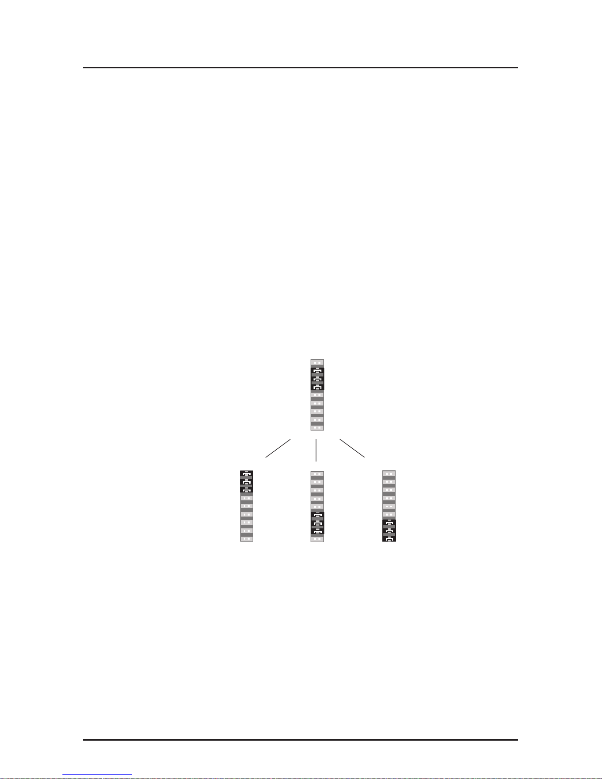
Configure your Client MultiVOIPs
The next step is to configure the MultiVOIPs designated as
“Client” units. The Client units can be another MVP400, a
MVP800 unit, MVP200 or a MultiVOIP 100 Series. Again,
unique LAN IP addresses, subnet masks, and Gateway IP
addresses are assigned, and each Voice/Fax channel is
configured for the appropriate channel interface type. When
this is done, the Phone Directory Database option is set to
Client, and the IP address of the Host MultiVOIP is entered.
Once all client units are configured, the process moves on to
Phase 3.
Deploy the VOIP Network
The final phase of installation is deployment of the network.
Through the first two phases, the VOIP administrator controls
configuration, so when the Client MultiVOIPs are sent to their

7
Introduction
remote sites, the remote site administrators need only to
connect the units to their LAN and telephone equipment. A full
Phone Directory Database (supplied by the Host MultiVOIP)
will be loaded into their unit within minutes of being connected
and powered up.
The final task of the VOIP Administrator is to develop the VOIP
Dialing Directory based on the Phone Directory Database and
the phone numbers of the interfacing telephone equipment.
Now, a VOIP User can call any person on the VOIP network.
MultiVOIP Quick Start Guide
8
Unpacking Your MultiVOIP
Remove all items from the box.
www.multitech.com
Voice/Fax over IP Networks
Figure 2. Unpacking
Safety Warnings
Caution
Danger of explosion if battery is incorrectly replaced.
A lithium battery on the voice/fax channel board provides
backup power for the time keeping capability. The battery has
an estimated life expectancy of ten years.
When the battery starts to weaken, the date and time may be
incorrect. If the battery fails, the board must be sent back to
Multi-Tech Sytems for battery replacement.
The E&M, FXS, and Ethernet ports are not designed to be
connected to a Public Telecommunication Network.
9
Cabling
Cabling Your MultiVOIP
Cabling your MultiVOIPinvolves connecting the host MultiVOIP
to your LAN and telephone equipment.
If you are connecting any Voice/Fax Channel to an E&M trunk
other than type 2, perform the E&M Jumper Block Positioning
procedure, which immediately follows the Cabling Procedure,
before performing the Cabling Procedure.
1. Connect one end of the power supply to a live AC outlet
and connect the other end to the MultiVOIP as shown in
Figure 3. The power connector is a 7-pin circular DIN
connector.
E&M FXO FXS E&M FXO FXS E&M FXO FXS
VOICE/
FAX
CHANNEL
8
VOICE/
FAX
CHANNEL
4
VOICE/
FAX
CHANNEL
7
VOICE/
FAX
CHANNEL
3
VOICE/
FAX
CHANNEL
6
VOICE/
FAX
CHANNEL
2
VOICE/
FAX
CHANNEL
5
VOICE/
FAX
CHANNEL
1
CHANNEL 10
CHANNEL 9
CHANNEL 8
CHANNEL 7
CHANNEL 6
CHANNEL 5
CHANNEL 4
CHANNEL 3
CHANNEL 2 (RS232/V.35)
CHANNEL 1 (RS232/V.35)
10BASET
ETHERNET
COMMAND PORT
EXT. COMPOSITE LINK (RS232/V.35)
POWER
I
O
GND
T1 DSU
MONITOR
XMT RCV
INTERNAL
COMPOSITE
LINK
E&M FXO FXS
Ethernet Connection
Command Port Connection
Power Connection
FXS
FXO
E&M
FXSE&M
FXO
PSTN
Voice/Fax Channel 1 - 8
Connections
Figure 3. Cable Connections
2. Connect the MultiVOIP to a PC by using the DB-9 to DB-25
cable provided with your unit. Plug the DB-25 end of the
cable into the Command port of the MultiVOIP and the
other end into the serial port on the PC. See Figure 3.

MultiVOIP Quick Start Guide
10
3. Connect a network cable to the ETHERNET 10BASET
connector on the back of the MultiVOIP. Connect the other
end of the cable to your network.
4. If you are connecting a station device such as an analog
telephone, a fax machine, or a Key Telephone System
(KTS) to your MultiVOIP, connect one end of an RJ11
phone cord to the Voice/Fax Channel 1 FXS connector on
the back of the MultiVOIP and the other end to the station
device.
If you are connecting a PBX extension to your MultiVOIP,
connect one end of an RJ11 phone cord to the Voice/Fax
Channel 1 FXO connector on the back of the MultiVOIP
and the other end to the PBX extension.
If you are connecting an E&M trunk from a telephone
switch to your MultiVOIP, connect one end of an RJ45
phone cord to the Voice/Fax Channel 1 E&M connector
on the back of the MultiVOIP and the other end to the
trunk. Refer to the User Guide for E&M pin assignments.
If you are connecting to an E&M trunk, you need to ensure
that the E&M trunk jumper is in the correct position for the
E&M type trunk. The default E&M jumper position is E&M
type 2. To change the E&M jumper position, perform the
E&M jumper block positioning procedure, which
immediately follows this procedure.
5. Repeat the above step to connect the remaining telephone
equipment to each Voice/Fax Channel on your MultiVOIP.
6. Turn on power to the MultiVOIP by placing the ON/OFF
switch on the back panel to the ON position. Wait for the
BOOT LED on the MultiVOIP to go off before proceeding.
This may take a couple minutes.
Proceed to the next section to load the MultiVOIP software.
11
Cabling
E&M Jumper Block Positioning Procedure
A jumper block exists for each voice/fax channel. The jumper
block is to the right of each set of channel jacks. The jumper
block contains 8-pairs of pins. The jumper plug fits over three
pairs of pins on the jumper block. The E&M type number is
labeled on the pc board. The jumper plug needs to be
centered on the E&M type number. Perform the following
procedure to change E&M jumper position.
1. Ensure that power is removed from the MultiVOIP.
2. Remove the front panel by loosening the two Phillips quarter
turn screws.
3. Remove the eight chassis mounting screws and slide the top
cover back off the chassis to expose the rear panel.
4. To change a jumper position, lift the jumper plug up off the
jumper block and move to the new position, ensuring that the
center jumper is centered on the E&M type number.
4
2 (Default)
1,3
5
5. Change the jumper position for each voice/fax channel
that is connecting to an E&M trunk that is not a type 2. If
you have two voice/fax channel boards in your unit and
you need to change the jumpers on the second board,
remove the six screws from the top board and disconnect
the ribbon cable from the top board.
6. Slide the top cover back on to the chassis and replace the
eight retaining screws removed in step 3.
7. Replace the front panel and secure it by tightening the two
Phillips quarter turn screws.

MultiVOIP Quick Start Guide
12
8. If you are using a Magix 400 E&M Tie Card, connect the
ground pin to the chassis ground screw as shown.
6
3
1
4
5
2
1
2
3
4
5
6
7
8
Male Male
PIN NO.
PIN NO.
MVP 400
Connection
Magix 400 E&M 4
Wire Tire Card
M MOUTH CONTROL
E EAR CONTROL
T1 TIP 1 RECEIVE
R RING TRANSMIT
T TIP TRANSMIT
R1 RING 1 RECEIVE
CHASSIS GROUND SCREW
UNUSED
M INPUT
E OUTPUT
T1 4-WIRE OUTPUT
R 4-WIRE INPUT, 2-WIRE
T 4-WIRE INPUT, 2-WIRE
R1 4-WIRE OUTPUT
SG (SIGNAL GND) OUTPUT
SB (SIGNAL BATTERY OUTPUT
9. Return to the Cabling Procedure.

13
Software Installation
Configuring Your Host MultiVOIP
The following software loading procedure does not provide
every screen or option in the loading process. The
assumption is that a technical person with a thorough
knowledge of Windows and the software loading process is
doing the installation. Additional information on the MultiVOIP
software is provided in the User Guide supplied with your
MultiVOIP.
If you are installing a MultiVOIP behind a firewall, you need to
add the following UDP ports to your firewall.
Q.931 Signaling, Ch1[900] Q.931 Signaling, Ch2 [902]
Q.931 Signaling, Ch3[904] Q.931 Signaling, Ch4 [906]
Status [5000]
Ch1 RTP [5004] Ch1 RTCP [5005]
Ch2 RTP[5006] Ch2 RTCP [5007]
Ch3 RTP[5008] Ch3 RTCP [5009]
Ch4 RTP[5010] Ch4 RTCP [5011]
Refer to your firewall user documentation to enter and open
these ports.
1. Verify that your MultiVOIP400 has been properly cabled
and that the power is turned on.
2. Insert the MultiVOIP400 CD into your CD-ROM drive. The
CD should start automatically. It may take 10 to 20
seconds for the MultiTech CD installation window to
display.
MultiVOIP Quick Start Guide
14
If the Multi-Tech Installation CD window does not display
automatically, click My Computer, then right click the CD
ROM drive icon, click Open, and then click the Autorun
icon.
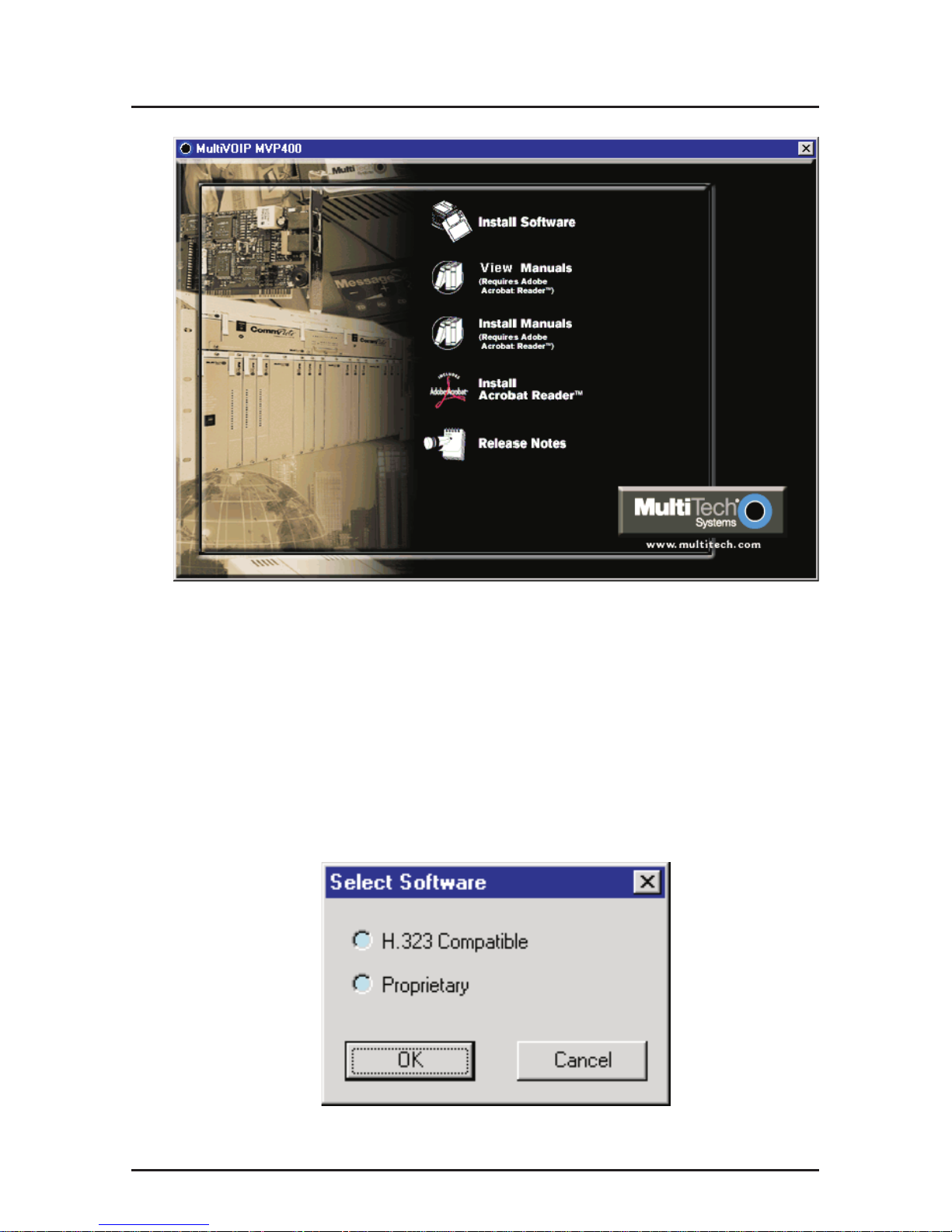
3. When the Multi-Tech Installation CD dialog box displays,
click the Install Software icon.
4. The Select Software dialog box is displayed. Select
Proprietary Software option.
15
Software Installation
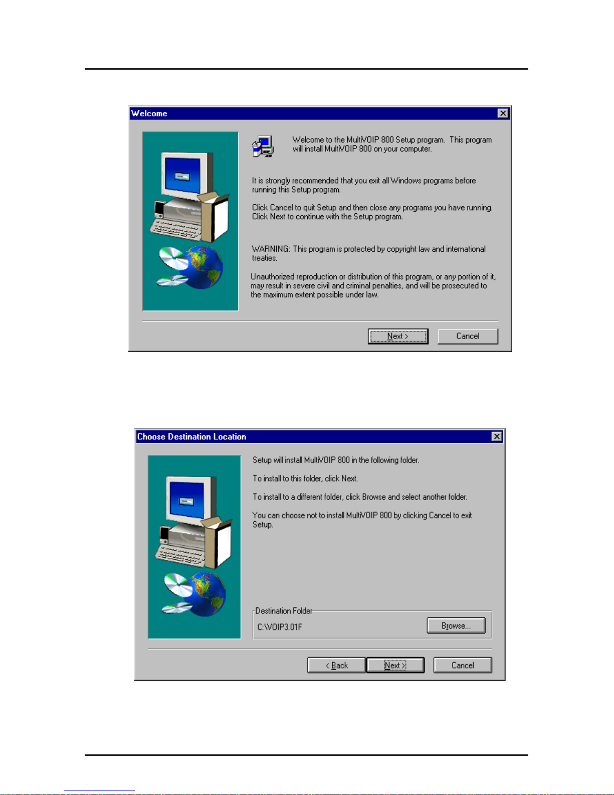
5. The Welcome dialog box displays.
Click Next to continue.
6. Follow the on-screen instructions to install your MultiVOIP
software.
You may choose the Destination Location of your
MultiVOIP software or you can choose to select the default
destination by clicking Next.
 Loading...