

Multitech MultiVOIP 200 MVP200, MultiVOIP MVP200 Quick Start Manual

Voice / Fax over IP Networks
Standalone V oice/IP Gateway
Model MVP200
H.323 Mode
Quick Start Guide

Quick Start Guide
S000335A Revision A
MultiVOIP 200 (Model MVP200)
This publication may not be reproduced, in whole or in part, without prior
expressed written permission from Multi-Tech Systems, Inc. All rights
reserved.
Copyright © 2004, by Multi-Tech Systems, Inc.
Multi-Tech Systems, Inc. makes no representations or warranties with
respect to the contents hereof and specifically disclaims any implied
warranties of merchantability or fitness for any particular purpose.
Furthermore, Multi-Tech Systems, Inc. reserves the right to revise this
publication and to make changes from time to time in the content hereof
without obligation of Multi-Tech Systems, Inc. to notify any person or
organization of such revisions or changes.
Record of Revisions
Revision Description
A Replacing printed Quick Start 82098177 and changing
(4/12/04) Master/Slave to Client/Host.
Patents
This Product is covered by one or more of the following U.S. Patent
Numbers:
5.682.386; 5.757.801; 6.151.333
. Other Patents Pending.
TRADEMARK
Trademark of Multi-Tech Systems, Inc. is the Multi-Tech logo.
Windows and Netmeeting are registered trademarks of Microsoft.
Multi-Tech Systems, Inc.
2205 Woodale Drive
Mounds View, Minnesota 55112
(763) 785-3500 or (800) 328-9717
U.S. Fax 763-785-9874
Technical Support (800) 972-2439
http://www.multitech.com

iii
Contents
Introduction ................................................................................... 4
Related Documentation ................................................................. 5
Installing Your MultiVOIP 200 ........................................................ 6
Installing and Configuring Your MultiVOIP 200........................ 6
Deploying the VOIP Network................................................... 7
Unpacking Your MultiVOIP 200...................................................... 8
Safety Warnings ............................................................................ 8
Cabling Your MultiVOIP 200........................................................... 9
Cabling Procedure .................................................................. 9
E&M Jumper Block Positioning Procedure .................................. 11
Installing Your MultiVOIP 200 Software ....................................... 12
Configuring Your MultiVOIP 200 .................................................. 17
Registering with a Gatekeeper Phone Directory ................... 28
Building a Proprietary Phonebook Directory ......................... 35
Configuring Your Slave MultiVOIP 200s ................................ 47
Deploying the VOIP Network ....................................................... 60
Remote Site Administrator .................................................... 61
Limited Warranty ......................................................................... 64
Technical Support ........................................................................ 65
FCC Declaration .......................................................................... 65
MultiVOIP Quick Start Guide
4
Introduction
Welcome to Multi-Tech's new stand-alone Voice/IP Gateway,
the MultiVOIP, model MVP200. The MultiVOIP 200 allows
analog voice and fax communication over an IP network. Multi-
Tech’s voice/fax gateway technology allows voice/fax
communication to be transmitted, with no additional expense,
over your existing IP network, which has traditionally been
data-only. To access this free voice and fax communication, all
you have to do is connect the MultiVOIP 200 to your telephone
equipment, and then to your existing Internet connection. Once
configured, the MultiVOIP 200 then allows voice and fax to
travel down the same path as your traditional data
communications.
The MultiVOIP 200 supports the H.323 standards-based
protocol enabling your MultiVOIP 200 to communicate with
other third-party VOIP Gateways or other endpoints that
support the H.323 protocol (e.g., Microsoft NetMeeting® ). The
H.323 standard defines how endpoints make and receive calls,
how endpoints negotiate a common set of audio and data
capabilities, and how information is formatted and sent over
the network. This version of the software also supports
communication with a Multi-Tech MVPGK1 Gatekeeper or an
optional 3rd party H.323 Gatekeeper which, when enabled,
maintains its own phonebook database, pre-registers all users,
controls the bandwidth, and handles all conferencing issues
such as transferring of calls.
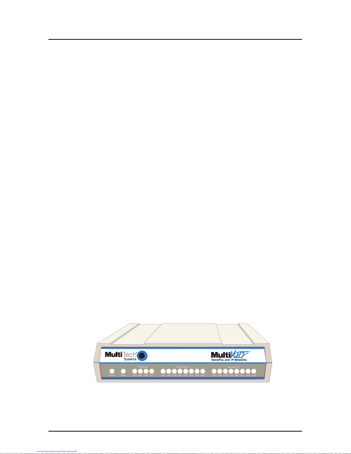
Figure 1. MultiVOIP 200

5
Introduction
The MVP200 has two independent voice/fax channels (each
with three voice/fax interfaces), a 10 Mbps Ethernet LAN
interface, and a Command port for configuration.
System management is provided through the Command port
using bundled Windows® software which provides easy-to-use
configuration menus and comprehensive on-line Help.
Related Documentation
The MultiVOIP 200 Quick Start Guide is intended to be used
by qualified systems administrators and network managers.
This Quick Start Guide provides the necessary information for
a qualified person to unpack, cable, load software, and
configure the unit for proper operation.
A detailed MultiVOIP 200 User Guide is included on your
system CD and provides in-depth information on the features
and functionality of Multi-Tech’s MultiVOIP 200.
The CD media is produced using Adobe AcrobatTM for viewing
and printing the user guide. To view or print your copy of a user
guide, load Acrobat ReaderTM onto your system from the CD,
or obtain it as a free download from Adobe’s Web site:
http://www.adobe.com
The MultiVOIP 200 User Guide is also available on Multi-
Tech’s Web site at:
http://www.multitech.com
Viewing and printing a user guide from the Web also requires
that you have the Acrobat Reader loaded on your system. To
select the MultiVOIP 200 User Guide from the Multi-Tech
Systems home page, click Documents, then click MultiVOIP in
the product list drop-down window, then click MultiVOIP
Manuals. All MultiVOIP 200 documents will be displayed at the
bottom of the page and you can choose
User Guide (MVP200)
to
view or download the .pdf file.

MultiVOIP Quick Start Guide
6
Installing Your MultiVOIP 200
The basic steps of installing your MultiVOIP 200 network
involve unpacking the units, connecting the cables, and
configuring the units using management software (MultiVOIP
200 Configuration). This process results in a fully functional
Voice Over IP network. A brief description is provided below
with detailed instructions provided later.
Installing and Configuring Your MultiVOIP 200
The VOIP administrator must first install the MultiVOIP 200
software and then configure each MultiVOIP 200 for its specific
function. During the configuration process, it’s important to
note that the Phone Directory Database is configured
differently depending on whether or not you have Gatekeeper
support on your VOIP network.
If your VOIP network supports an H.323 Gatekeeper, you
must register all H.323 endpoints with the Gatekeeper. The
procedure for doing this is explained in the section
“Registering with a Gatekeeper Phone Directory.”
If your VOIP network does not have Gatekeeper software or
the Gatekeeper software is not enabled, then you must build a
proprietary phonebook with a “Host” MultiVOIP 200 and
“Client” MultiVOIP 200s. The “Host” unit includes the
assignment of a unique LAN IP address, subnet mask, and
Gateway IP address; as well as the selection of appropriate
channel interface type for each of the Voice/Fax channels.
Once all connections have been made, the VOIP administrator
configures the unit and builds the Phone Directory Database
that will reside in the Host unit.
After the “Host” MultiVOIP 200 is configured, the administrator
moves on to configure the MultiVOIP 200(s) designated as
“Client” units. Again, unique LAN IP addresses, subnet masks,
and Gateway IP addresses are assigned, and each Voice/Fax
channel is configured for the appropriate channel interface
type. When this is done, the Phone Directory Database option

7
Introduction
is set to Client, and the IP address of the Host MultiVOIP 200
is entered. Once all Client units are configured, the process
moves on to the “Deploying the VOIP Network” section.
Deploying the VOIP Network
The final phase of the installation is deployment of the network.
When the remote MultiVOIP 200s are sent to their remote
sites, the remote site administrators need only connect the
units to their LAN and telephone equipment. A full Phone
Directory Database (supplied by the Host MultiVOIP 200
Proprietary Phonebook will be loaded into their units within
minutes of being connected and powered up.
For remote VOIPs that were configured with the Gatekeeper
option enabled, each MultiVOIP 200 will be registered with the
Gatekeeper (i.e., the Gatekeeper phonebook directory is NOT
downloaded to the remote units).
MultiVOIP Quick Start Guide
8
Unpacking Your MultiVOIP 200
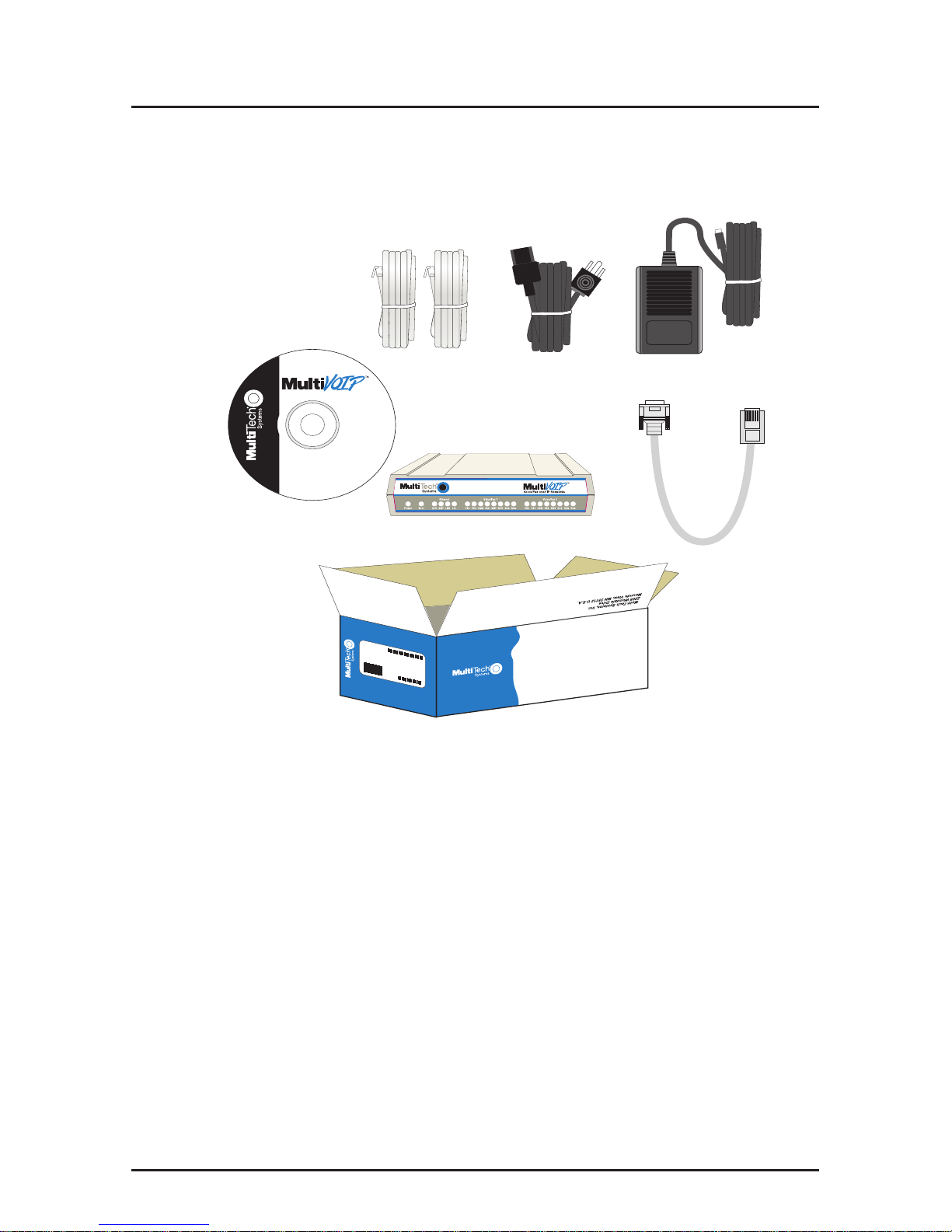
Remove all items from the box. (See Figure 2.)
M
A
D
E
IN
U
.S
.A
M
A
D
E
IN
U
.S
.A
www.multitech.com
Voice/Fax over IP Networks
200
Figure 2. Unpacking
Safety Warnings
Caution: Danger of explosion if battery is incorrectly replaced.
A lithium battery on the circuit board provides backup power
for the time keeping capability. The battery has an estimated
life expectancy of ten years.
When the battery starts to weaken, the date and time may be
incorrect. If the battery fails, the board must be sent back to
Multi-Tech Systems for battery replacement.
The E&M, FXS, and Ethernet ports are not designed to be
connected to a Public Telecommunication Network.
9
Cabling
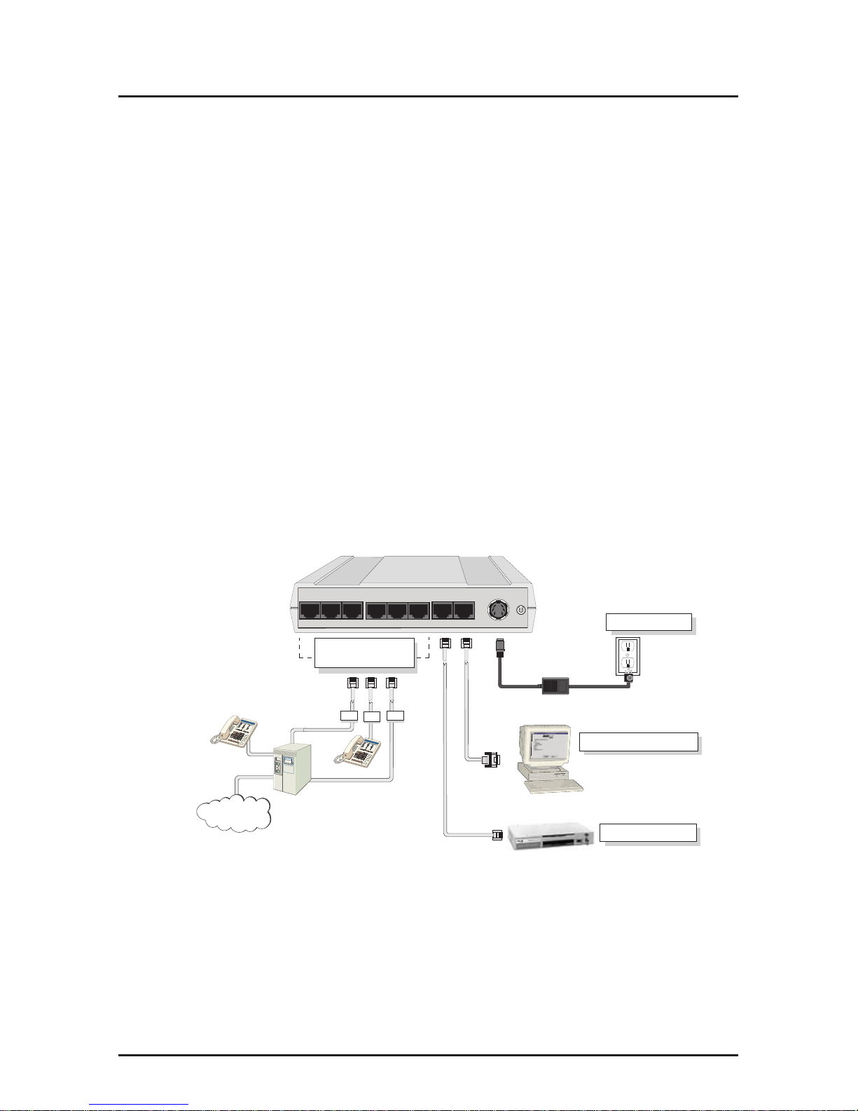
Cabling Your MultiVOIP 200
Cabling your MultiVOIP 200 involves making the proper Power,
Command Port, and Internet connections. Figure 6 shows the
back panel connectors and the associated cable connections.
The Cabling Procedure section provides step-by-step
instructions for cabling your MultiVOIP 200.
Note: Before cabling your MultiVOIP 200, perform the E&M
Jumper Block Positioning Procedure if either voice/fax channel
(1 or 2) will be connected to an E&M trunk that is a Type 1,3, 4,
or 5 rather than a Type 2 (the default).
Cabling Procedure
1. Using the supplied cable, connect the power supply to a
live AC outlet, then plug the power supply into the
MultiVOIP 200 as shown in Figure 3. The power connector
is a 6-pin circular DIN connector.
Voice/Fax Channel
1 & 2 Connections
Network Connection
Power Connection
FXS
E&M FXO
PSTN
Command Port Connection
Hub
PBX
Voice/Fax Channel 1
E&M FXS FXO
Voice/Fax Channel 2
FXO FXS E&M
1
0
Power
Ethernet RS232
Command
10Base-T
Figure 3. Cable Connections
2. Connect the MultiVOIP 200 to a PC using the RJ-45 to
DB9 (female) cable provided with your unit. Plug the RJ-45
end of the cable into the Command port of the MultiVOIP
200 and connect the other end to the PC’s serial port
(Figure 3).

MultiVOIP Quick Start Guide
10
3. Connect a network cable to the Ethernet 10Base-T
connector on the back of the MultiVOIP 200. Connect the
other end of the cable to your network.
4. If you are connecting a station device; e.g., analog
telephone, fax machine, or Key Telephone System (KTS)
to your MultiVOIP 200, connect the smaller end of a
special adapter cable (supplied) to the Voice/Fax Channel
1 FXS connector on the back of the MultiVOIP 200 and the
other end to the station device.
If you are connecting a PBX extension to your MultiVOIP
200, connect the smaller end of a special adapter cable
(supplied) to the Voice/Fax Channel 1 FXO connector on
the back of the MultiVOIP 200 and the other end to the
PBX extension.
If you are connecting an E&M trunk from a telephone
switch to your MultiVOIP 200, connect one end of an RJ45 cable (not supplied) to the Voice/Fax Channel 1 E&M
connector on the back of the MultiVOIP 200 and the other
end (8 spade lugs or 8 wires to connect directly to the
punch-down block) to the PBX trunk card.
Note: For customers building their own E&M connector,
App. B of the User Guide has a pinout diagram showing
the E&M back panel connector on the MultiVOIP 200.
5. Repeat step 4 to connect the remaining phone equipment
to each Voice/Fax Channel on your MultiVOIP 200.
6. Turn on power to the MultiVOIP 200 by setting the power
switch on the back panel to the 1 (up, On) position. Wait for
the Boot LED on the MultiVOIP 200 to go Off before
proceeding. This may take a couple of minutes.
If you need to change the E&M Jumper Block positioning,
refer to the following section; otherwise, proceed to the
Software Loading section to load MultiVOIP 200 software.
11
Cabling
E&M Jumper Block Positioning Procedure
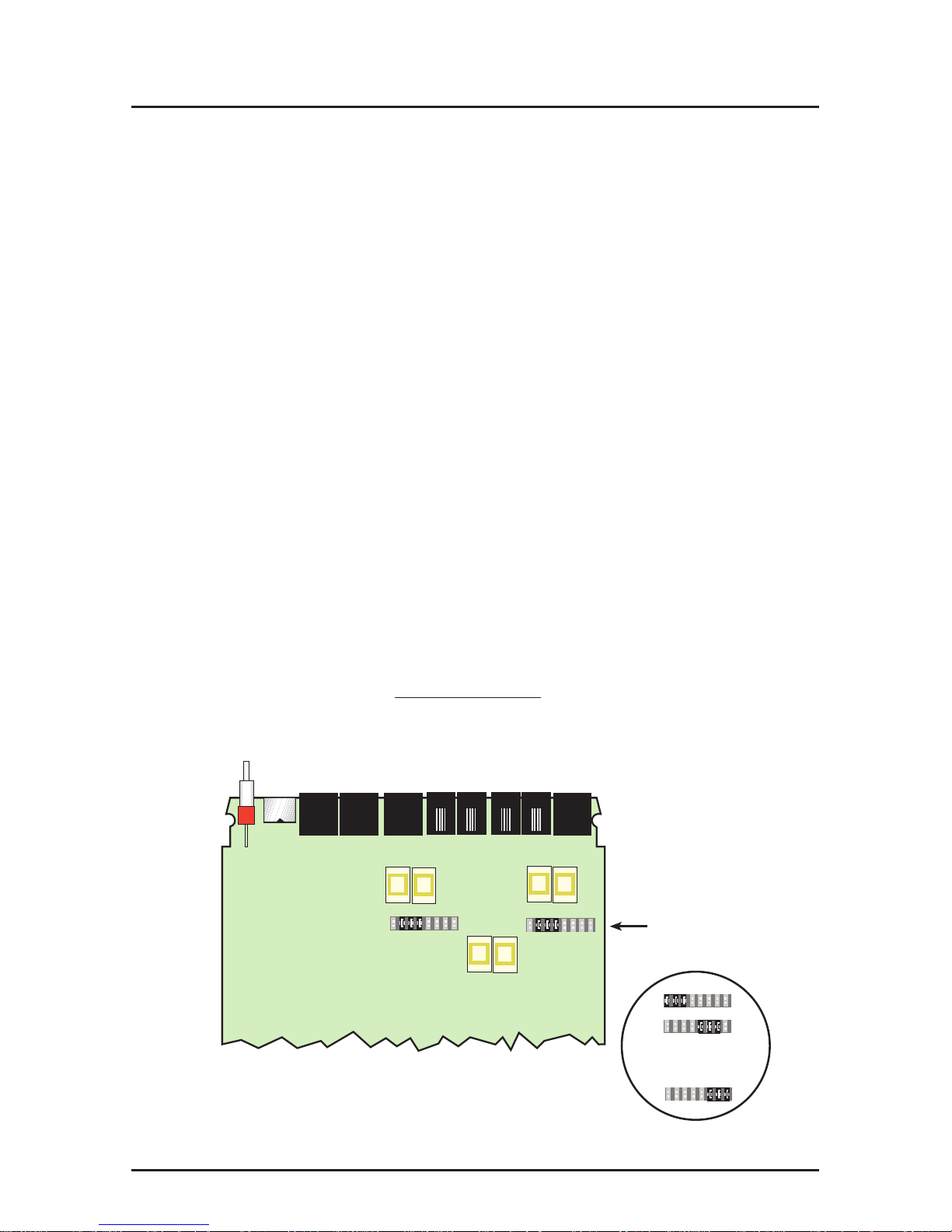
Each voice/fax channel on the MultiVOIP 200 has a separate
E&M jumper block located near the jacks on the back panel of
the MultiVOIP 200. Each jumper block has 8 pairs of pins with
a jumper plug on three adjacent pairs of pins. The jumper plug
must be centered on the E&M type number (see Figure 4) that
matches the E&M connection for that channel. Perform the
following procedure if you need to move the E&M jumper block
from its default (Type 2) position.
1. Ensure that the external power supply is disconnected
from the MultiVOIP 200.
2. Turn the MultiVOIP 200 upside down and remove the
cabinet mounting screw at the center back of the cabinet.
3. Return the MultiVOIP 200 to its upright position, then slide
the base out the rear of the cabinet.
Note: To change a jumper position, lift the jumper plug up
off the jumper block, then move it to the new position,
ensuring that the middle jumper of the jumper block is
centered on the E&M type number (1,3,4,or 5) as shown
on Figure 4. (Note: Numbers are
not
on the board.)
Jumper Blocks
In Position 2
(Default)
Note: Markings do not appear on board.
Back Panel Connectors
2
2
Channel 2
Channel 1
Alternate Positions
4
5
1,3
Figure 4. E&M Jumper Block Positions

MultiVOIP Quick Start Guide
12
4. Change the jumper block position for any voice/fax
channel to be connected to an E&M trunk that is not a
Type 2 (the default position).
5. Slide the base all the way into the cabinet until it stops.
6. Turn the MultiVOIP 200 upside down and replace the
cabinet mounting screw that was removed in step 2.
7. If you are using a Magix 400 E&M Tie Card, connect the
ground pin to the chassis ground screw as shown.
6
3
1
4
5
2
1
2
3
4
5
6
7
8
Male Male
PIN NO.
PIN NO.
MVP 200
Connection
Magix 400 E&M 4
Wire Tire Card
M MOUTH CONTROL
E EAR CONTROL
T1 TIP 1 RECEIVE
R RING TRANSMIT
T TIP TRANSMIT
R1 RING 1 RECEIVE
CHASSIS GROUND SCREW
UNUSED
M INPUT
E OUTPUT
T1 4-WIRE OUTPUT
R 4-WIRE INPUT, 2-WIRE
T 4-WIRE INPUT, 2-WIRE
R1 4-WIRE OUTPUT
SG (SIGNAL GND) OUTPUT
SB (SIGNAL BATTERY OUTPUT
8. Return the MultiVOIP 200 to its upright position, then
perform the cabling procedure.

13
Installing the Software
Installing Your MultiVOIP 200 Software
The following installation procedures do not provide every
screen or option in the process of installing the MultiVOIP 200
software. It is assumed that a technical person with a thorough
knowledge of Windows and the software loading process is
doing the installation. Once you have installed the software,
you will be instructed on how to configure your MultiVOIP 200,
and finally, on how to deploy your MultiVOIP 200. Additional
information on the MultiVOIP 200 software is provided in the
on-line Help.
Note: The phonebook directory configuration process is
different depending on whether or not you have an enabled
H.323 Gatekeeper resident in your network. The section on
“Configuring Your MultiVOIP 200” will explain these differences.
CAUTION: If you are installing a MultiVOIP 200 behind a
Firewall, the Firewall must support H.323. Refer to your
Firewall user documentation to enable H.323 support.
1. Make certain that your MultiVOIP 200 has been properly
cabled and that it is powered on.
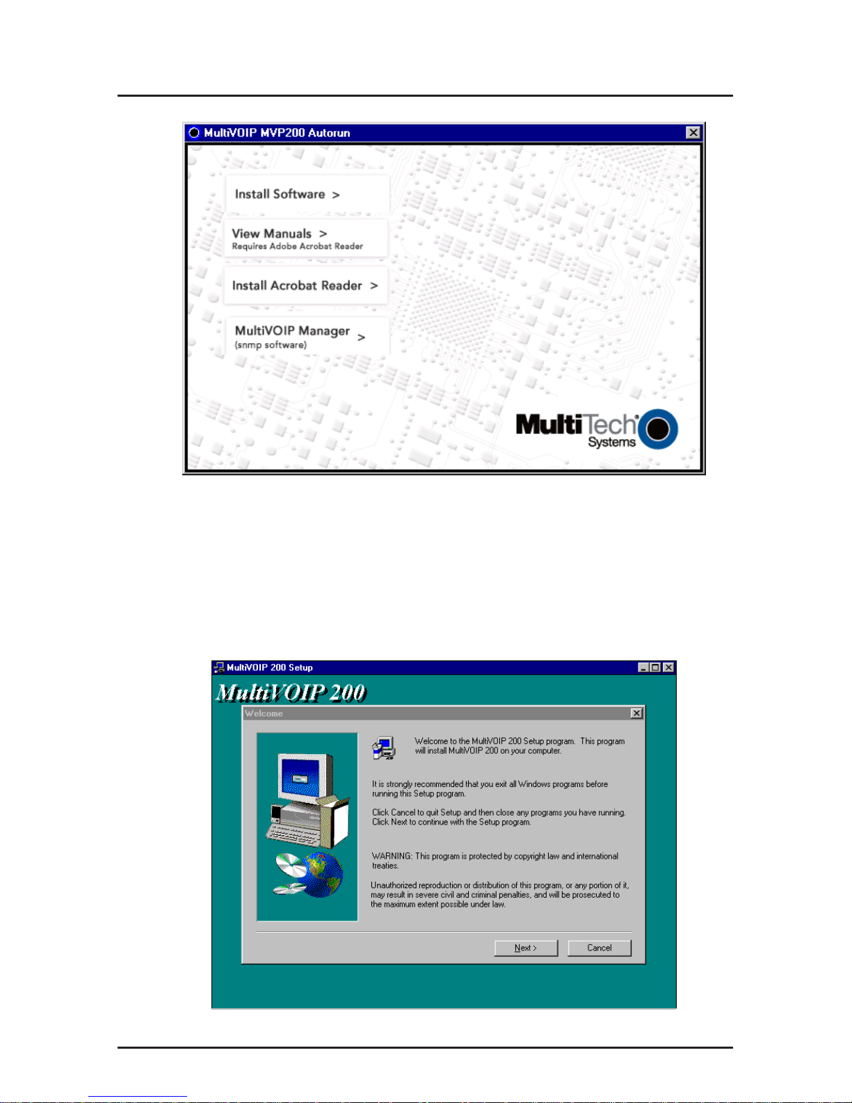
2. Insert the MultiVOIP 200 CD into a CD-ROM drive. The
CD is auto-detectable, so it starts automatically. It may
take 10 to 20 seconds for the Multi-Tech Installation CD
screen to appear.
MultiVOIP Quick Start Guide
14
If the Multi-Tech Installation CD Screen does not appear
automatically, click My Computer, then right-click the CD-
ROM drive icon, click Open, then click the Autorun icon.
3. When the Multi-Tech Installation CD Screen is displayed,
click the Install Software icon.
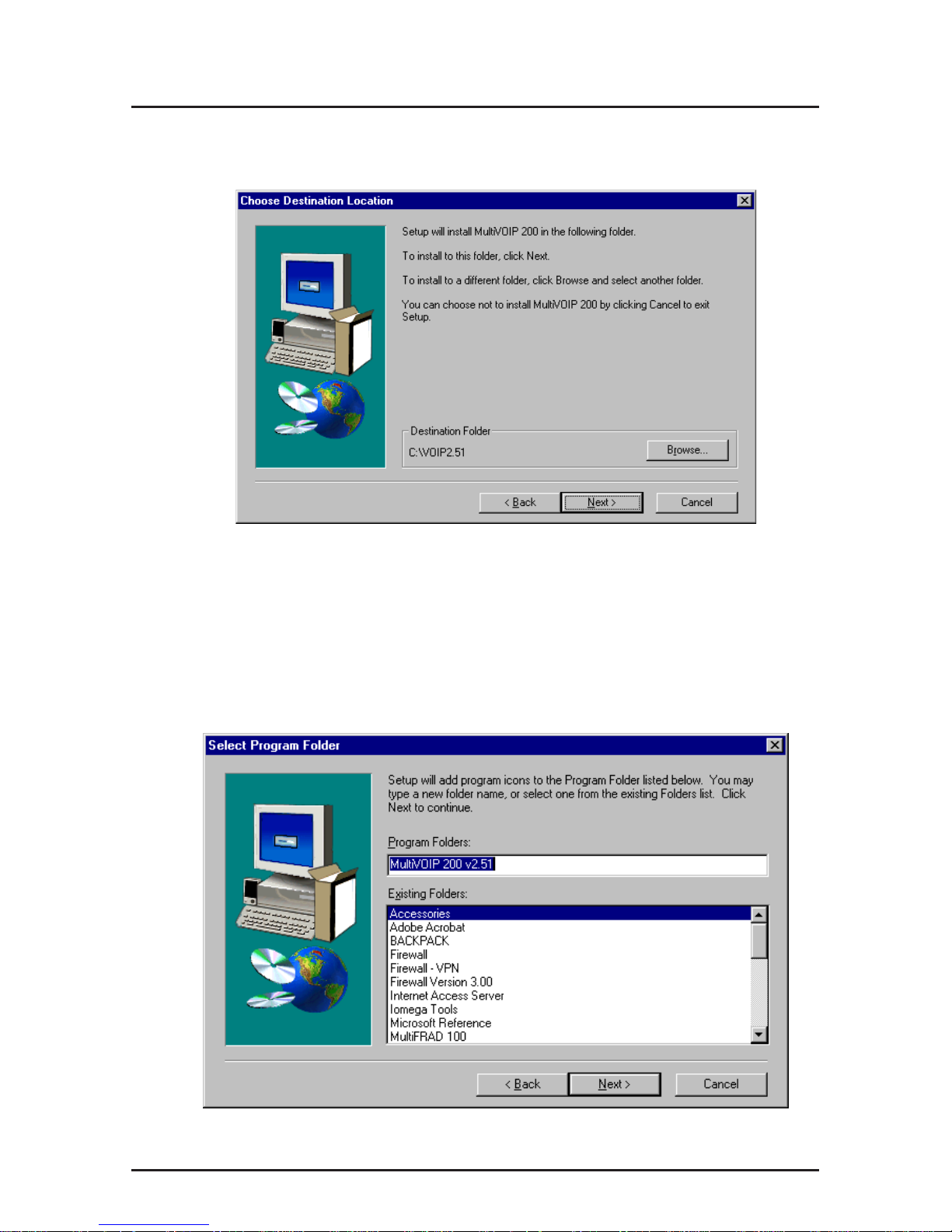
4. The MultiVOIP 200 Setup welcome screen is displayed.
Press Enter or click Next> to continue.
15
Installing the Software
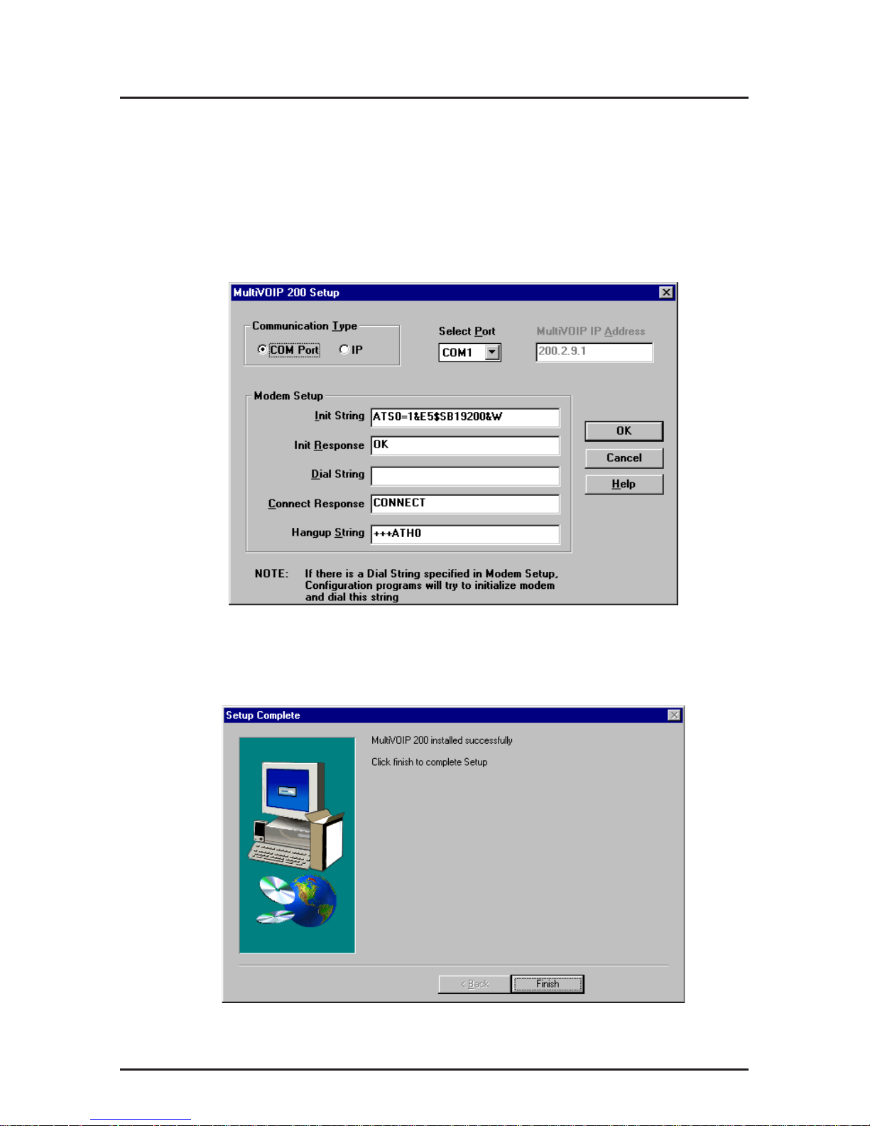
5. The Choose Destination Location dialog box is
displayed. Follow the on-screen instructions.
You can either choose the Destination Location of your
MultiVOIP 200 software or select the default destination by
clicking Next>. If you click Browse, you can select a
different destination folder for the MultiVOIP 200 software.
6. The Select Program Folder dialog box enables you to
choose where you want the program file to be located.
Verify the path and click Next > to continue.
MultiVOIP Quick Start Guide
16
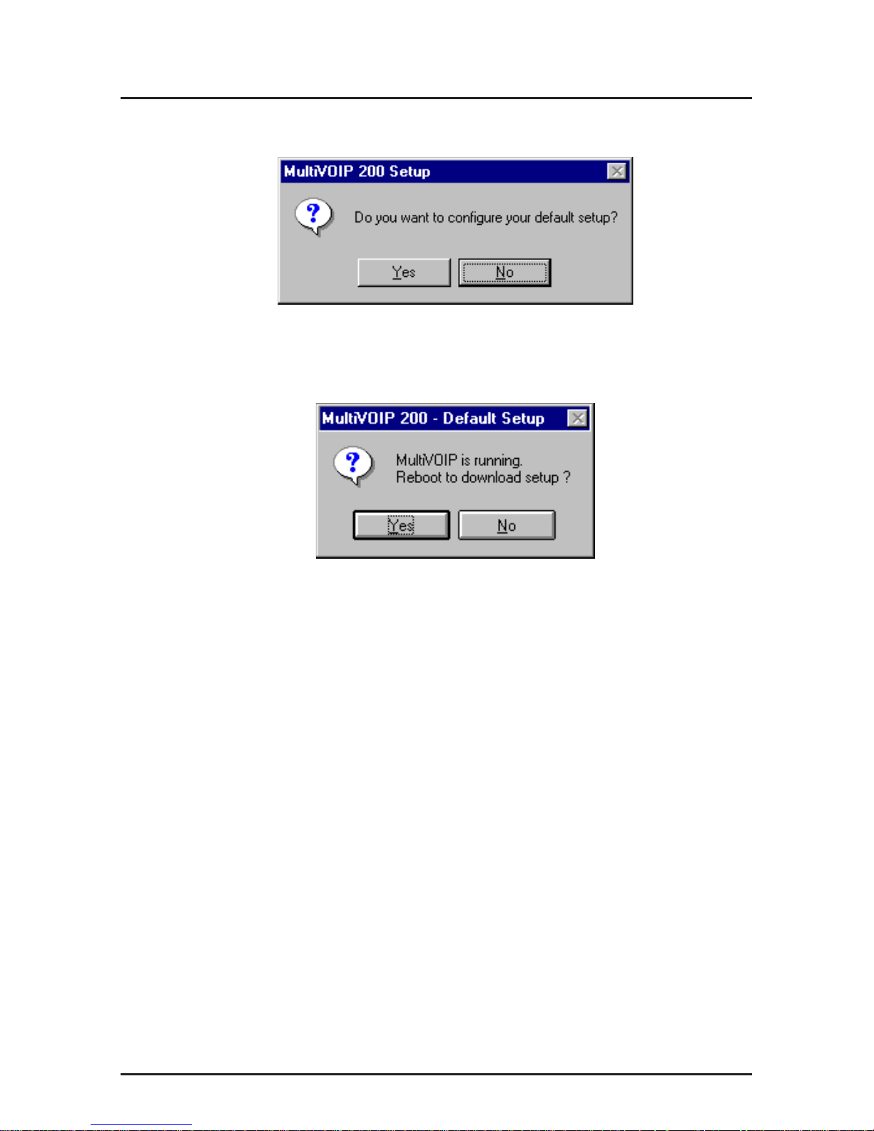
7. The Copying program files ... screen is displayed
followed by the MultiVOIP 200 Setup dialog box. This
dialog box enables you to select the COM port of your PC
that is connected to the Command port of the MultiVOIP
200. From the Select Port drop-down list, choose the
COM port of your PC.
Click OK to continue.
8. The Setup Complete dialog is displayed.
Click Finish to continue.
17
Installing the Software
9. The following message is displayed:
Click Yes to continue.
10. The following message is displayed.
Click Yes to continue.
MultiVOIP Quick Start Guide
18
Configuring Your MultiVOIP 200
The following steps provide instructions for configuring your
MultiVOIP 200. The configuration sequence includes IP
Protocol default setup, Channel setup, and Phone Directory
Database setup. The Phone Directory Database setup is
configured differently depending on whether or not the
Gatekeeper function is available and enabled on the Phone
Directory Database dialog box.
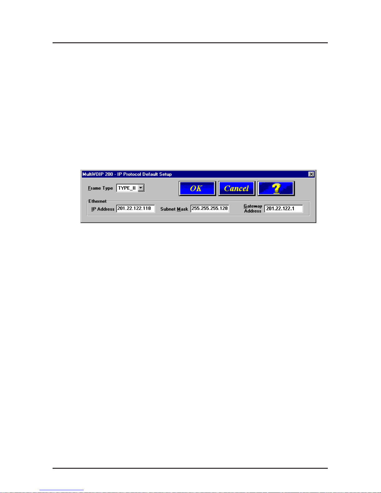
11. The IP Protocol Default Setup dialog box is displayed.
The default Frame T ype is TYPE_II. If this does not match
your IP network, change the Frame Type by clicking the
drop-down arrow and selecting SNAP. The available Frame
Type choices are TYPE_II and SNAP.
12. In the Ethernet group, enter the IP Address, Subnet
Mask, and Gateway Ad dress unique to your IP LAN in
the corresponding fields.
The IP address is the unique LAN IP address that is
assigned to the MultiVOIP 200, and the Gateway address
is the IP address of the device connecting your MultiVOIP
200 to the Internet.
Click OK when you are finished.
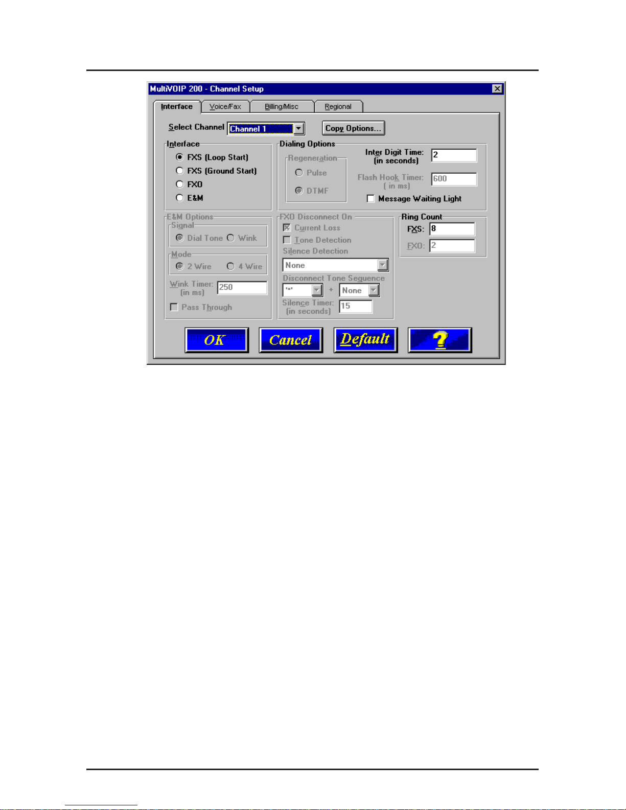
13. The Channel Setup dialog box is displayed. The four tabs
in this dialog box define the channel interface, voice/fax
parameters, billing/miscellaneous parameters, and
regional telephone parameters for each channel.
19
Configuring the MultiV OIP
Configure each channel for the type of interface you are
connecting to. The Interface tab defaults to Channel 1 in
the Select Channel field. To change the channel number,
click the drop-down arrow and the list of channels is
displayed. Highlight the channel you want to configure.
Note: Feature options are enabled or disabled (grayed out)
according to the interface type that you select. The one
option available for all interface types is the Inter Digit
Time option. This option defines the maximum amount of
time that the unit will wait before mapping the dialed digits
to an entry in the Phone Directory Database. If too much
time elapses between digits, and the wrong numbers are
mapped, you will hear a rapid busy signal. If this happens,
it will be necessary to hang up and dial again. The default
setting is 2 seconds.
14. The Interface group defaults to FXS (Loop Start). Select
the interface option that corresponds to the interface type
being connected to the Voice/Fax Channel 1 jack on the
back panel of the MultiVOIP 200.

MultiVOIP Quick Start Guide
20
FXS (Loop Start): If a station device; e.g., an analog
telephone, fax machine, or KTS (Key Telephone System) is
connected to the Voice/Fax connector on the back of the
unit, FXS (Loop Start) will likely be the correct Interface.
FXS (Ground Start): If the station device uses ground
start, then choose the FXS (Ground Start) option. Refer to
the device’s user documentation.
For both FXS Loop Start and FXS Ground Start , the Ring
Count FXS window allows you to set the maximum
number of rings output on the FXS interface before
hanging up and releasing the line to another call. The
default setting is 8 rings.
Note: Zero (0) means no rings - caller hears a busy tone.
FXO: If you are using an analog extension from your PBX,
then choose the FXO option. Check with your in-house
phone personnel to verify the connection type.
If FXO is selected, the Dialing Options Regeneration,
Flash Hook Timer , and Ring Count groups are enabled.
Check with your local in-house phone personnel to verify
whether your local PBX dial signaling is Pulse or tone
(DTMF). Then, set the Regeneration option accordingly.
The Flash Hook Timer allows you to enter the time, in
milliseconds, for the duration of the flash hook signals
output on the FXO interface. The default setting is 600
milliseconds. The Ring Count FXO window allows you to
set the number of rings received on the FXO interface
before the MultiVOIP 200 answers the incoming call. The
default setting is 2 rings.
Note: Zero (0) means that the MultiVOIP 200 never
answers.

21
Configuring the MultiV OIP
For FXO-to-FXO communications, you can enable a
specific type of FXO Disconnect; Current Loss, Tone
Detection, or Silence Detection. (Check with your in-
house phone personnel to verify the preferred type of
disconnect to use.) Enabling Tone Detection activates the
Disconnect Tone Sequence options. For Disconnect Tone
Sequence, you can select from drop-down lists either one
or two tones that will cause the line to be disconnected;
the person hanging up a call must then hit the key(s) that
will produce those tones. For Silence Detection, select
One Way or Two Way, then set the timer for the number of
seconds of silence before disconnect. Note that the default
value of 15 seconds may be shorter than desired for your
application.
E&M: If you are connecting to an analog E&M trunk on
your PBX, then choose the E&M interface option to enable
the E&M Options group. Check with your local in-house
phone personnel to determine if the signaling is Dial Tone
or Wink and if the connection is 2-wire or 4-wire. If Wink
signaling is used, then the Wink Timer is enabled with a
default of 250 milliseconds. The range of the Wink Timer is
from 100 to 350 milliseconds. Consult with your local inhouse phone personnel for this timer setting.
Note: After configuring a given channel (1 or 2), you can
copy that channel’s configuration by clicking the Copy
button and everything on the Interface tab will be copied
to the other channel.
15. Repeat the above step to configure the interface type for
voice/fax channel 2.
 Loading...