

Page 1

Voice / Fax over IP Networks
Voice/Fax Over IP Networks
Model MVP200
H.323 Mode
User Guide
Page 2

User Guide
S0000073 Revision D
MultiVOIP 200 (Model MVP200)
This publication may not be reproduced, in whole or in part, without prior expressed written permission from MultiTech Systems, Inc. All rights reserved.
Copyright © 2004, by Multi-Tech Systems, Inc.
Multi-Tech Systems, Inc. makes no representations or warranties with respect to the contents hereof and
specifically disclaims any implied warranties of merchantability or fitness for any particular purpose. Furthermore,
Multi-Tech Systems, Inc. reserves the right to revise this publication and to make changes from time to time in the
content hereof without obligation of Multi-Tech Systems, Inc. to notify any person or organization of such
revisions or changes.
Record of Revisions
Revision Description
C Added H.323 protocol support; covers software version 2.51. All pages at revision C.
(1/12/01)
D Updated to software version 2.52.
(4/12/04)
Patents
This Product is covered by one or more of the following U.S. Patent Numbers:
Patents Pending.
TRADEMARK
Multi-Tech and the Multi-Tech logo are registered trademarks and MultiVOIP is a trademark of Multi-Tech
Systems, Inc.
5.682.386; 5.757.801; 6.151.333
. Other
Adobe Acrobat is a trademark of Adobe Systems Incorporated.
Microsoft Windows, Windows 2000, Windows 98, Windows 95, Windows NT, and NetMeeting are either
registered trademarks or trademarks of Microsoft Corporation in the United States and/or other countries.
Multi-Tech Systems, Inc.
2205 Woodale Drive
Mounds View, Minnesota 55112
(763) 785-3500 or (800) 328-9717
Fax 763-785-9874
Technical Support (800) 972-2439
Internet Address: http://www.multitech.com
Page 3

Contents
Chapter 1 - Introduction and Description.....................................................5
Introduction ................................................................................................................................................ 6
Preview of this Guide ................................................................................................................................. 7
Typical Application ...................................................................................................................................... 8
Front Panel Description ............................................................................................................................ 13
Back Panel Description ............................................................................................................................ 14
Power Connector ............................................................................................................................... 14
Command Connector ......................................................................................................................... 14
10Base-T (Ethernet) Connector ......................................................................................................... 14
Voice/Fax Channel 1 and 2 ................................................................................................................ 14
Specifications ........................................................................................................................................... 15
Ethernet Port...................................................................................................................................... 15
Command Port ................................................................................................................................... 15
Voice/Fax Channel 1 and 2 ................................................................................................................ 15
Electrical/Physical .............................................................................................................................. 15
Chapter 2 - Installation................................................................................. 17
Installing Your MultiVOIP 200 ................................................................................................................... 18
Installing and Configuring Your MultiVOIP 200...................................................................................18
Deploying the VOIP Network.............................................................................................................. 18
Safety Warning Telecom ........................................................................................................................... 18
Unpacking Your MultiVOIP 200 ................................................................................................................. 19
Safety Warnings ....................................................................................................................................... 19
Valid VOIP Network Connections ............................................................................................................. 19
Cabling Your MultiVOIP 200...................................................................................................................... 20
Cabling Procedure ............................................................................................................................. 20
E&M Jumper Block Positioning Procedure ............................................................................................... 22
Chapter 3 - Software Loading and Configuration...................................... 23
Installing Your MultiVOIP 200 Software .................................................................................................... 24
Configuring Your MultiVOIP 200 ............................................................................................................... 27
Registering with a Gatekeeper Phone Directory ................................................................................ 32
Building a Proprietary Phonebook Directory.....................................................................................36
Configuring Your Client MultiVOIP 200s ............................................................................................. 43
Deploying the VOIP Network .................................................................................................................... 50
Remote Site Administrator ................................................................................................................. 50
Chapter 4 - MultiVOIP 200 Software............................................................51
Introduction .............................................................................................................................................. 52
Before You Begin................................................................................................................................ 52
MultiVOIP 200 Configuration .................................................................................................................... 53
Changing Channel Parameters ................................................................................................................ 54
Interface ............................................................................................................................................. 54
Voice/Fax ........................................................................................................................................... 56
Billing/Misc ......................................................................................................................................... 57
Regional ............................................................................................................................................. 58
Changing the Phone Directory Database ................................................................................................. 59
Proprietary Phone Directory Database .............................................................................................. 60
Gatekeeper Phone Directory Database .............................................................................................62
Changing IP Parameters .......................................................................................................................... 65
Viewing Call Progress .............................................................................................................................. 66
iii
Page 4

Applications Setup.................................................................................................................................... 67
Viewing Statistics ..................................................................................................................................... 68
IP Statistics ........................................................................................................................................ 68
SNMP Statistics ................................................................................................................................. 69
Viewing Logs ............................................................................................................................................ 70
Viewing Log Entry Details .................................................................................................................. 70
Viewing Channel Totals ...................................................................................................................... 71
Reports .................................................................................................................................................... 71
Upgrade Procedures ................................................................................................................................ 72
Upgrade Software .............................................................................................................................. 72
Chapter 5 - Remote Configuration and Management................................ 75
Introduction .............................................................................................................................................. 76
Remote Configuration .............................................................................................................................. 76
Modem-Based ................................................................................................................................... 76
LAN-Based ....................................................................................................................................... 78
Remote Management ............................................................................................................................... 80
Telnet ................................................................................................................................................. 80
WEB Management ............................................................................................................................. 82
Chapter 6 - Warranty, Service and T ech Support .......................................83
Introduction .............................................................................................................................................. 84
Limited Warranty ...................................................................................................................................... 84
On-line Warranty Registration ........................................................................................................... 84
Service ..................................................................................................................................................... 85
U.S. and Canadian Customers ........................................................................................................... 85
International Customers (outside U.S.A. and Canada) ...................................................................... 85
International Distributors .................................................................................................................... 86
Replacement Parts ............................................................................................................................ 86
Technical Support .............................................................................................................................. 86
Internet Sites...................................................................................................................................... 86
Appendixes ...................................................................................................87
Appendix A - TCP/IP Description ............................................................................................................. 88
Appendix B - Cabling Diagrams ............................................................................................................... 91
Appendix C - Regulatory Information ....................................................................................................... 93
Class A Statement ............................................................................................................................. 93
Fax Branding Statement .................................................................................................................... 93
FCC Part 68 Telecom ......................................................................................................................... 94
Canadian Limitations Notice .............................................................................................................. 95
EMC, Safety and Terminal Directive Compliance............................................................................... 95
Glossary........................................................................................................ 97
Index............................................................................................................110
iv
Page 5

Voice / Fax over IP Networks
Chapter 1 - Introduction and Description
Page 6
MultiVOIP 200 User Guide
Introduction
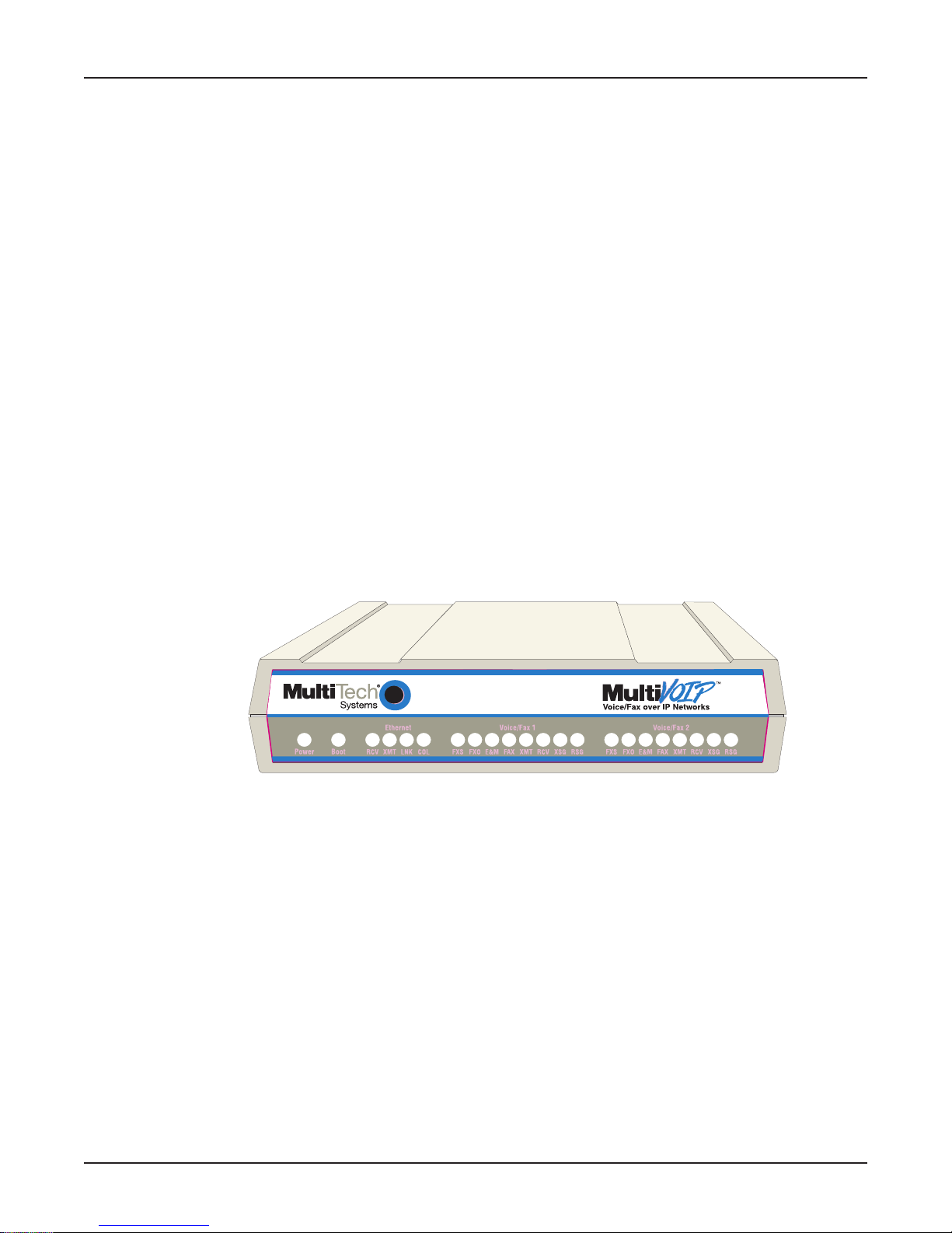
Welcome to Multi-Tech's new voice/fax gateway, the MultiVOIP, model MVP200. The MultiVOIP 200
allows analog voice and fax communication over a traditional data communications/data networking
digital Internet. Multi-Tech’s new voice/fax gateway technology allows voice and fax communication
to be transmitted, with no additional expense, over your existing communications Internet, which has
traditionally been data-only. To access this free voice and fax communication, all you have to do is
connect the MultiVOIP 200 to a phone or to your existing in-house phone switch and then to your
existing Internet connection. Once configured, the MultiVOIP 200 allows voice and fax to travel down
the same path as your traditional data communications.
The MultiVOIP 200 supports the H.323 standards-based protocol enabling your MultiVOIP 200 to
participate in real-time conferencing with other third-party VOIP Gateways or endpoints that support
the H.323 protocol (e.g., Microsoft Netmeeting
and receive calls, how endpoints negotiate a common set of audio and data capabilities, how
information is formatted and sent over the network, and how endpoints communicate with their
respective Gatekeepers. Gatekeeper software is optional and if present in a network, it typically
resides on a designated PC. It acts as the central point for all calls within its zone and provides call
control services to all registered endpoints. In addition, Gatekeepers can perform bandwidth
management through support for Bandwidth Request, Confirm, and Reject messages.
Note: A zone consists of all H.323 endpoints that are under the Gatekeeper’s control.
®
). The H.323 standard defines how endpoints make
The MVP200 is designed with two voice/fax channels (which offer three voice/fax interfaces on each
channel), a 10 Mbps Ethernet LAN interface, and a command port for configuration.
System management is provided through the command port using bundled Windows® software which
provides easy-to-use configuration menus and a comprehensive Help system.
Figure 1-1. MultiVOIP 200
6
Page 7

Preview of this Guide
This guide describes the MultiVOIP 200 and tells you how to install and configure the unit. The
information contained in each chapter is as follows:
Chapter 1 - Introduction and Description
Chapter 1 describes the MultiVOIP 200 and provides a typical application, describes front panel
indicators, back panel connector descriptions, and lists relevant specifications.
Chapter 2 - Installation
Chapter 2 provides information on unpacking and cabling your MultiVOIP 200. The installation
procedure describes each cable connection.
Chapter 3 - Software Loading and Configuration
Chapter 3 provides instructions for software loading and initial configuration. Later chapters, as well
as the on-line Help, describe the MultiVOIP 200 software in more detail.
Chapter 4 - MultiVOIP 200 Software
Chapter 4 describes the MultiVOIP 200 software package designed for the Windows environment.
For explanations and parameters of each field within a dialog box, refer to the Help.
Chapter 1 - Introduction and Description
Chapter 5 - Remote Configuration and Management
Chapter 5 provides procedures for changing the configuration of a remote MultiVOIP 200. Remote
configuration enables you to change the configuration of a unit by simply connecting two modems
between the two MultiVOIP 200s and remotely controlling the unit. Chapter 5 also describes typical
client applications (i.e., Telnet and Web-based management) used for remote configuration of the
MultiVOIP 200.
Chapter 6 - Warranty, Service and Tech Support
Chapter 6 provides instructions on getting service for your MultiVOIP 200 at the factory, a statement
of the limited warranty, information about our Internet presence, and space for recording information
about your MultiVOIP 200 prior to calling Multi-Tech’s Technical Support.
7
Page 8
MultiVOIP 200 User Guide
T ypical Application
Before Voice Over IP (VOIP), i.e., voice over the Internet, a corporate office had a data connection to
the Internet and a voice connection to the public switched telephone network (PSTN). With VOIP, the
two networks can be tied together. To accomplish this, a MultiVOIP 200 is connected between the
public switched telephone network and the data network at the corporate office as shown in the
typical VOIP application in Figure 1-2. The remote branch office has two standard telephones
connected to the MultiVOIP and its Ethernet connection is plugged into the hub on the data network.
The data network is connected via a router to the Internet. In our typical application, a user at the
corporate office picks up a telephone connected to their local telephone switch (PBX) and calls the
remote branch office by dialing extension 4124 on the corporate MultiVOIP. When the second dial
tone is heard, the caller then dials extension 301 at the remote branch office. The remote branch
office telephone rings and a voice conservation takes place.
Optional
H.323 Gatekeeper
IP Address 201.22.122.110
Port Number 1719
MultiVOIP
IP Address
201.22.122.118
Mask 255.255.255.128
512-4123
Corporate Office
Workstation
Workstation
LAN
HUB
512-4122
Fax
Web Server
Analog Connections
Channel 1: FXO
Channel 2: FXO
102
101
4124
PSTN Connection
(T1/E1, PRI, etc.)
Router (with Diffserv)
IP Address 201.22.122.1
Mask 255.255.255.128
4125
P
B
X
ISP
Internet/Intranet
IP Network
PSTN
Workstation
Router Static IP
Address 209.96.211.90
Remote Branch
Office
MultiVOIP
IP Address 206.25.124.120
Mask 255.255.255.240
Workstation
LAN
HUB
Router (with Diffserv)
IP Address 206.25.124.110
Mask 255.255.255.240
#301
#302
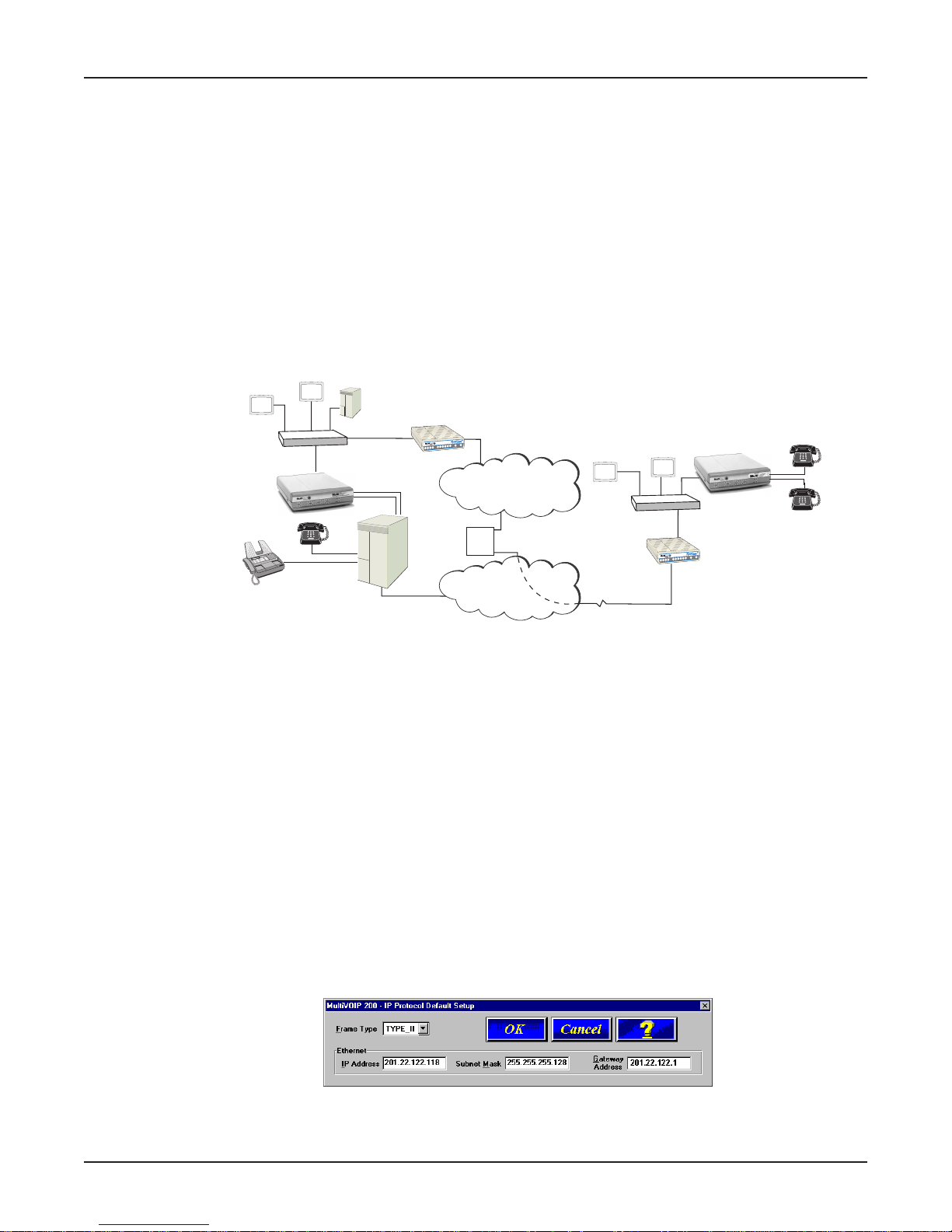
Figure 1-2. Typical VOIP Application
To set up this VOIP network, a MultiVOIP 200 at the corporate office is connected between the data
network and the corporate telephone switch (PBX). To connect the MultiVOIP 200 to the data
network, an Ethernet cable is connected to the Ethernet port on the unit and the other end is plugged
into a hub on the data network. On the phone side, two phone cords are connected to two FXO jacks
on the back of the MultiVOIP 200 and attached to two station lines on the phone switch. These two
lines on the PBX occupy phone extensions 4124 and 4125.
To set up a MultiVOIP 200 at the remote branch office, the Ethernet jack on the MultiVOIP 200 is
connected to the hub and the two analog phones are connected by phone cords to the FXS jacks on
the MultiVOIP 200.
To configure a MultiVOIP 200, the COM port of a PC is connected to the Command port on the
MultiVOIP 200. Configuration software is loaded onto your PC and your unique LAN parameters must
be established. The configuration software is based on a standard Windows Graphical User
Interface (GUI) which simplifies your selection process to a single parameter group within a dialog
box. For example, your LAN IP parameters are contained on a single dialog box (see below). You
can configure your network IP address and mask for the MultiVOIP 200 and the gateway address for
the corporate router on the same dialog box.
For your corporate MultiVOIP, the Ethernet Frame Type is Type II, the IP Address is 201.22.122.118,
the Subnet Mask Address is 255.255.255.128, and the router Gateway Address is 201.22.122.1. The
remote branch office would have the same Frame Type, a LAN IP address of 206.25.124.120 and a
8
Page 9
Chapter 1 - Introduction and Description
Gateway Address of 206.25.124.110. Once the LAN parameters are established, you can set up the
voice channel parameters.
The channel setup parameters define the voice side of the MultiVOIP, that is, the voice channel
interface; FXS (Ground and Loop Start) are for connecting to a standard analog telephone set, FXO
(Foreign Exchange Office) interface connects to the station side of a PBX, and E&M (Ear and Mouth)
connects to the trunk side of the PBX. Along with each interface there are additional parameters that
need to be considered, such as for FXO, the dialing options for DTMF (Touchtone) or Pulse, the
method of disconnecting (Current Loss or Tone Detection), and for E&M, signaling, mode, and the
wink timer settings in milliseconds.
Additional channel setup parameters cover the voice coder, DTMF gain, voice gain, and faxing in the
Voice/Fax tab of the Channel Setup dialog box. The most important parameter in this group is to
ensure that the voice coder is the same for all MultiVOIPs in the network. The Billing/Misc tab
handles the billing options, automatic disconnect options, and the dynamic jitter buffer options. The
jitter options in this tab handle voice break up which can be particularly disruptive to voice
communications. For the most part, these parameters can remain in their default values. The
Regional tab defines the country or region the MultiVOIP is being used in.
In our typical application, you would configure the corporate office channel parameters for an FXO
interface. With this interface, the defaults for the Dialing Options and the type of Disconnect could
remain as the defaults. For the remote branch office, the interface would be FXS with Loop Start
being used in most cases.
9
Page 10
MultiVOIP 200 User Guide
Once you have completed channel setup, you will need to add the phone numbers to the phone
directory database. Before you set up the phone directory database, you need to consider how the
database is going to be used; are you going to have an H.323 Gatekeeper setup your call sessions
or are you going to control your call sessions using the proprietary phone book. The H.323
Gatekeeper acts as the central point for all calls within its zone and provides call control services to
registered endpoints. If you choose the proprietary phone book, you establish a Host-Client
relationship where the Host MultiVOIP maintains the phone directory and downloads the directory to
each Client unit.
The decision on building the phone directory database is contained in the Phone Directory Database
dialog box. Before you choose how the data base is going to be used, here are a couple of things to
keep in mind; (1) If a Gatekeeper is employed in the network, you need to choose the Gatekeeper
option. You can not mix the Proprietary PhoneBook with the Gatekeeper. If you choose the
Gatekeeper option you can communicate with other third party endpoints that support H.323 (e.g.,
Microsoft Netmeeting). (2) If you choose the Proprietary PhoneBook, you establish a Host-Client
relationship in that the Host MultiVOIP maintains the phone directory database. All of the phone
numbers are listed in the data base so that if you want to communicate with someone in your VOIP
network, you can see the phone number in your data base. Everytime you bring up your MultiVOIP
the current phone directory is downloaded to your MultiVOIP.
The Gatekeeper is a separate application that can operate on a network pc and provides all the
controls needed to create, control, and manage an H.323 network zone. The H.323 network zone is
all the endpoints (terminals and gateways (MultiVOIPs)) that are registered with the gatekeeper. The
gatekeeper functions are address translation from LAN aliases for terminals and gateways to IP
addresses as defined in the RAS (Registration/Admission/Status) specification. The RAS Protocol
defines the communication with a gatekeeper and support for RTP/RTCP for sequencing audio
packets. The H.323 Gatekeeper also provides call-authorization for both accepting and placing calls
in its zone, and certain monitoring features (i.e., call permissioning and address resolution).
So, if you choose the Gatekeeper option, initially you need to communicate with the administrator of
the Gatekeeper to register your MultiVOIP. The information you need from the Gatekeeper
administrator is the IP address of the Gatekeeper and its port number. Then you need to establish
your alias address which includes phone number, channel number, H323 ID which is a name, and
your MultiVOIP LAN IP address. The port number is 1720, but if the Gatekeeper uses a different port
number, you have to ensure that you use the same port number. The Gatekeeper administrator will
then enter your information into the Gatekeeper data base. This concludes the preregisteration.
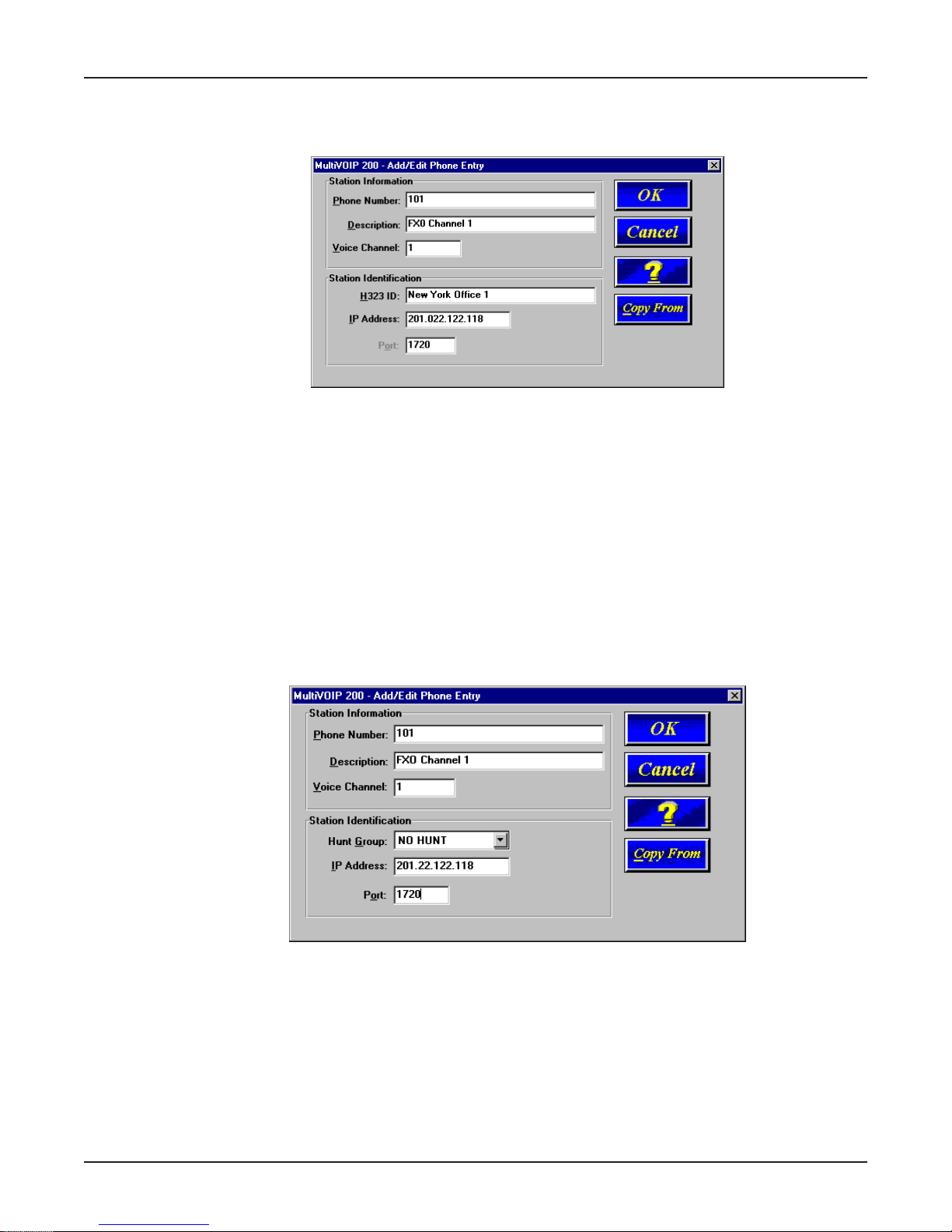
Now, you can enter your alias address information into the Add/Edit Phone Entry dialog box. For
example, if you were setting up the corporate MultiVOIP, you could enter the following information for
10
Page 11
Chapter 1 - Introduction and Description
Voice Channel 1. For instance, in our typical application channel 1 of the corporate MultiVOIP uses
extension 101. The Description is optional, but can be helpful if you assigned to a particular
individual or department, or in this case it defines the channel interface.
The H323 ID that was assigned to this phone number which identifies the office that is using this
extension. The IP Address of the Corporate MultiVOIP is 201.022.122.118 and the default port
number 1720 is used.
So now when you “come alive”, the Gatekeeper will register you with the above alias address. No
other H323 endpoint can use this alias. This is like your own telephone number.
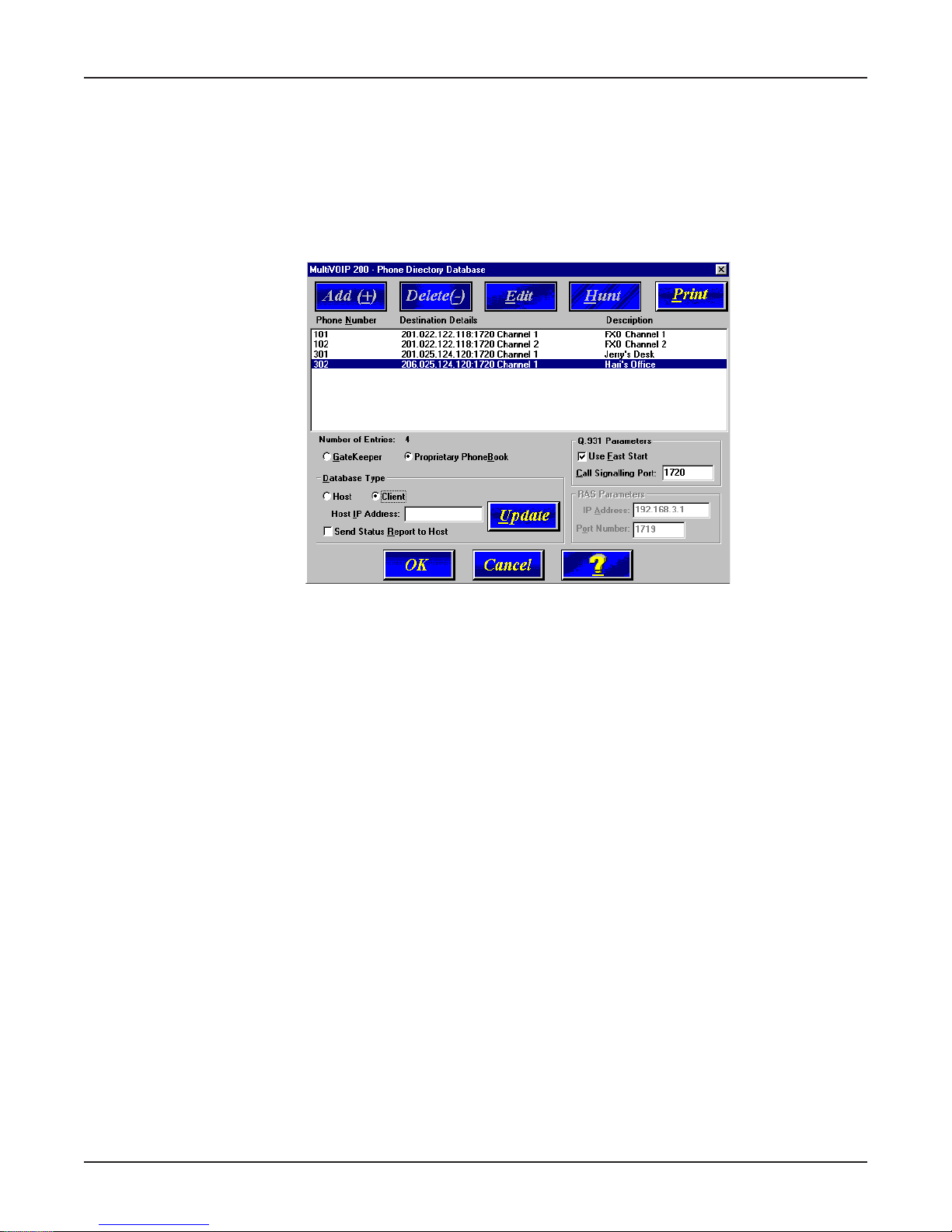
Now, if you choose the Proprietary PhoneBook option in the Phone Directory Database dialog box
instead of the Gatekeeper option, the Database Type group would become active and the RAS
Parameters group is inactive (greyed out).
Now, lets change the typical application to not have the Gatekeeper control the call session. When
you elect to use the Proprietary PhoneBook, you set up a Host-Client relationship. This relationship
allows one MultiVOIP to maintain the Phone Directory Database and publish this data base to all
MultiVOIP participants in the network. This proprietary data base allows you to see all the
participants in your network and provides you with there phone numbers.
Lets again start with the corporate MultiVOIP and we will set up the database so that the corporate
MultiVOIP can call the remote branch office and the remote branch office can call the corporate
MultiVOIP. To do this, the Phone Directory Database will have two entries for the corporate office and
two entries for the Remote Branch Office. Extension 101 at the corporate office is tied to voice
channel 1 and extension 102 to channel 2. The Description again ties to the type of interface used
on the corporate MultiVOIP (FXO). The Hunt Group in this situation is set for No Hunt. But if you
wanted to activate a Hunt Group, i.e., if an extension on the MultiVOIP is busy and you wanted to
look for another extension, you can assign a hunt group to those extensions. So that, say extension
101 is busy, the corporate MultiVOIP would roll over to extension 102.
11
Page 12
MultiVOIP 200 User Guide
Again, the IP Address of the corporate MultiVOIP needs to be added and the port number is 1720.
This adds phone number 101 of the corporate MultiVOIP to the proprietary data base. Now, to add
extension 102 to the proprietary data base, all you have to do is change the Phone Number and
Description to support channel 2 of the corporate MultiVOIP. After you have added channel 2, you
need to include the two channels at the remote branch office.
The proprietary data base would then appear as in the following dialog box and when the remote
branch office MultiVOIP is turned on, the current data base would be down loaded to the remote
branch office MultiVOIP.
12
Page 13
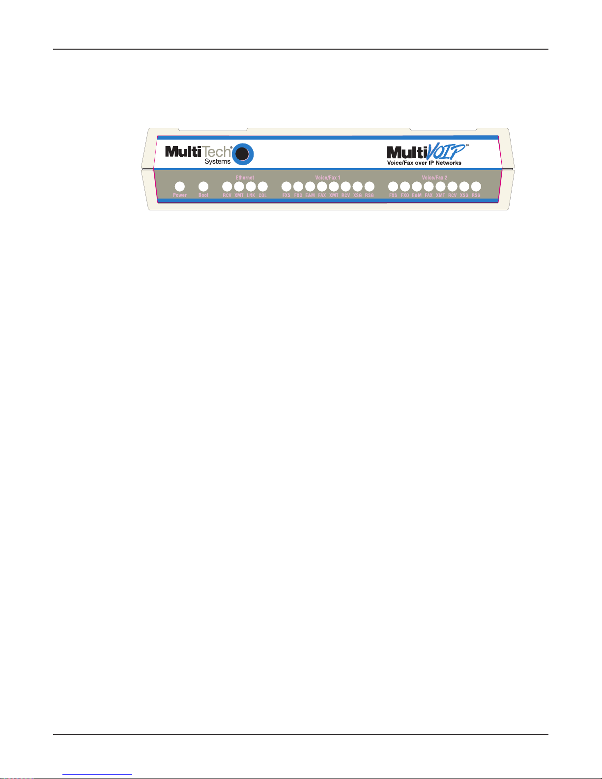
Front Panel Description
The MVP200 front panel has three groups of LEDs that provide the status of the Ethernet connection
(Ethernet), Voice/Fax channels (Voice/Fax 1 and 2), and general status of the MultiVOIP 200 (Boot
and Power). The front panel is shown in Figure 1-4 and a description of each LED follows.
Ethernet
RCV Receive Data indicator blinks when packets are being received from the local area network.
XMT Transmit Data indicator blinks when packets are being transmitted to the local area network.
LNK Link indicator lights when the Ethernet link senses voltage from a concentrator or external
device.
Chapter 1 - Introduction and Description
Figure 1-4. Front Panel
COL Collision indicator lights when a collision is detected on the Ethernet link.
Voice/Fax 1 and 2
FXS Foreign Exchange Station indicator lights when the voice/fax channel is configured for FXS
operation.
FXO Foreign Exchange Office indicator lights when the voice/fax channel is configured for FXO
operation.
E&M Ear and Mouth indicator lights when the voice/fax channel is configured for E&M operation.
FAX Fax indicator lights when there is fax traffic on the voice/fax channel.
XMT Transmit indicator blinks when voice packets are being transmitted to another H.323 end-
point.
RCV Receive indicator blinks when voice packets are being received from another H.323 endpoint.
XSG Transmit Signal indicator lights when the FXS-configured channel is off-hook, the FXO-
configured channel is receiving a ring from the Telco, or the M (Mouth) lead is active on the
E&M configured channel.
RSG Receive Signal indicator lights when the FXS-configured channel is ringing, the FXO-config-
ured channel has taken the line off-hook, or the E (Ear) lead is active on the E&M-configured
channel.
Boot
The Boot indicator lights when the MultiVOIP 200 is booting or downloading setup.
Power
The Power indicator lights when power is applied to the MultiVOIP 200.
13
Page 14

MultiVOIP 200 User Guide
Back Panel Description
The cable connections for the MultiVOIP 200 are made at the back panel. Connectors include Power,
Command Port (RS-232), Ethernet (10BASE-T), and Voice/Fax Channels 1 and 2 (E&M, FXO and
FXS). The cable connectors are shown in Figure 1-5 and defined in the following groups.
Voice/Fax Channel 1
E&M FXS FXO
Voice/Fax Channel 2
FXO FXS E&M
Ethernet RS232
Command
10Base-T
Power
1
0
Figure 1-5. Back Panel
Power Connector
The Power connector is used to connect the external power supply to the MultiVOIP 200. The Power
connector is a 6-pin circular DIN connector. A standard computer power cord connects the power
supply to a live AC grounded outlet.
Command Connector
The Command connector is used to configure the MultiVOIP 200 using a PC with an available serial
port and running Windows software. The Command connector is an RJ-45 jack (an adapter cable is
provided to convert to a standard serial port DB9 female connector).
10Base-T (Ethernet) Connector
The Ethernet 10Base-T connector is used to connect the MultiVOIP 200 to a LAN using unshielded
twisted cable. This connector is an RJ-45 jack.
Voice/Fax Channel 1 and 2
The Voice/Fax Channel connectors include three options per channel: E&M, FXS and FXO.
E&M - This connector is used for connecting Voice/Fax Channel 1 or 2 to the E&M trunk on a PBX.
This connector is an RJ-45 jack.
FXS - This connector is used for connecting Voice/Fax Channel 1 or 2 to a station device; e.g., an
analog phone, a KTS (Key Telephone System) phone system, or a fax machine. This connector is an
RJ-14 jack.
FXO - This connector is used for connecting Voice/Fax Channel 1 or 2 to the station side of a PBX.
This connector is an RJ-14 jack.
14
Page 15

Specifications
• One 4 MB DRAM (1 Meg by 32-bit, 70 nanosecond SIMM)
Caution: SIMM speed and size cannot be mixed
• Two Megs of flash memory
Ethernet Port
• Single Ethernet Interface - 10Base-T (twisted pair) keyed RJ-45 connector.
Command Port
• Single 19.2 Kbps asynchronous Command Port using an RJ-45 to DB9 cable with a DB9
female connector
Voice/Fax Channel 1 and 2
• Two RJ-14 jacks (FXO and FXS)
• One RJ-45 jack (E&M)
Electrical/Physical
Chapter 1 - Introduction and Description
• Voltage - 115 VAC (Standard), 240 Volts AC (Optional)
• Frequency - 47 to 63 Hz
• Power Consumption - 18 Watts
• Dimensions - 1.625" high x 6.175" wide x 9" deep
(4.13 cm x 15.68 cm x 22.86 cm)
• Weight - 2 pounds (0.9 kg)
15
Page 16

MultiVOIP 200 User Guide
16
Page 17

Voice / Fax over IP Networks
Chapter 2 - Installation
Page 18

MultiVOIP 200 User Guide
Installing Y our MultiVOIP 200
The basic steps of installing your MultiVOIP 200 network involve unpacking the units, connecting the
cables, and configuring the units using management software (MultiVOIP 200 Configuration). This
process results in a fully functional Voice Over IP network. A general description is provided below
and detailed instructions are provided in Chapter 3, Software Loading and Configuration.
Installing and Configuring Your MultiVOIP 200
The VOIP administrator must first install the MultiVOIP 200 software and then configure each
MultiVOIP 200 for its specific function. During the configuration process, it’s important to note that the
Phone Directory Database is configured differently depending on whether or not you have
Gatekeeper support on your VOIP network.
If your VOIP network supports Gatekeeper software, you must register all H.323 endpoints with the
Gatekeeper. The procedure for doing this is explained in the section “Registering with a Gatekeeper
Phone Directory.”
If your VOIP network does not have Gatekeeper software or the Gatekeeper software is not enabled,
then you must build a proprietary phonebook with a “Host” MultiVOIP 200 and “Client” MultiVOIP
200s. The “Host” unit includes the assignment of a unique LAN IP address, subnet mask, and
Gateway IP address; as well as the selection of appropriate channel interface type for each of the
Voice/Fax channels. Once all connections have been made, the VOIP administrator configures the
unit and builds the Phone Directory Database that will reside with the Host unit.
Once configuration of the “Host” MultiVOIP 200 has been completed, the administrator moves on to
configure the MultiVOIP 200(s) designated as “Client” units. Again, unique LAN IP addresses, subnet
masks, and Gateway IP addresses are assigned, and each Voice/Fax channel is configured for the
appropriate channel interface type. When this is done, the Phone Directory Database option is set to
Client, and the IP address of the Host MultiVOIP 200 is entered. Once all Client units are configured,
the process moves on to the “Deploying the VOIP Network” section.
Deploying the VOIP Network
The final phase of the installation is deployment of the network. When the remote MultiVOIP 200s are
sent to their remote sites, the remote site administrators need only to connect the units to their LAN
and telephone equipment. A full Phone Directory Database (supplied by the Host MultiVOIP 200
Proprietary Phonebook will be loaded into their units within minutes of being connected and powered
up. For remote VOIPs that were configured with the Gatekeeper option enabled, each MultiVOIP 200
will be registered with the Gatekeeper (i.e., the Gatekeeper phonebook directory is NOT downloaded
to the remote units). The final task of the VOIP administrator or the Gatekeeper administrator is to
develop the VOIP Dialing Directory based on the appropriate phone directory database (i.e., the
Proprietary phonebook database or the Gatekeeper phonebook database).
Safety Warning Telecom
1. Never install phone wiring during a lightning storm.
2. Never install phone jacks in wet locations unless the jacks are designed for wet locations.
3. This product is to be used with UL and cUL listed computers.
4. Never touch uninsulated phone wires or terminals unless the phone line has been disconnected
at the network interface.
5. Use caution when installing or modifying phone lines.
6. Avoid using a phone (other than a cordless type) during an electrical storm. There may be a
remote risk of electrical shock from lightning.
7. Do not use the phone to report a gas leak in the vicinity of the leak.
8. To reduce the risk of fire, use only No. 26 AWG or larger Telecommunication line Cord.
18
Page 19

Unpacking Your MultiVOIP 200
Remove all items from the box. (See Figure 2-1.)
Chapter 2 - Installation
Safety Warnings
Caution: Danger of explosion if battery is incorrectly replaced.
A lithium battery on the circuit board provides backup power for the time keeping capability. The
battery has an estimated life expectancy of ten years.
When the battery starts to weaken, the date and time may be incorrect. If the battery fails, the board
must be sent back to Multi-Tech Systems for battery replacement.
Voice/Fax over IP Networks
www.multitech.com
200
M
A
D
E
I
N
U
.
S
.
A
E
D
A
M
Figure 2-1. Unpacking
A
.
S
.
U
N
I
The E&M, FXS, and Ethernet ports are not designed to be connected to a Public Telecommunication
Network.
V alid VOIP Network Connections
The following VOIP network interface connections (calls) can be made.
• FXS to FXS
• FXS to E&M
• FXS to FXO
• FXO to FXO
• FXO to FXS
• FXO to E&M
• E&M to E&M
• E&M to FXS
• E&M to FXO
19
Page 20
MultiVOIP 200 User Guide
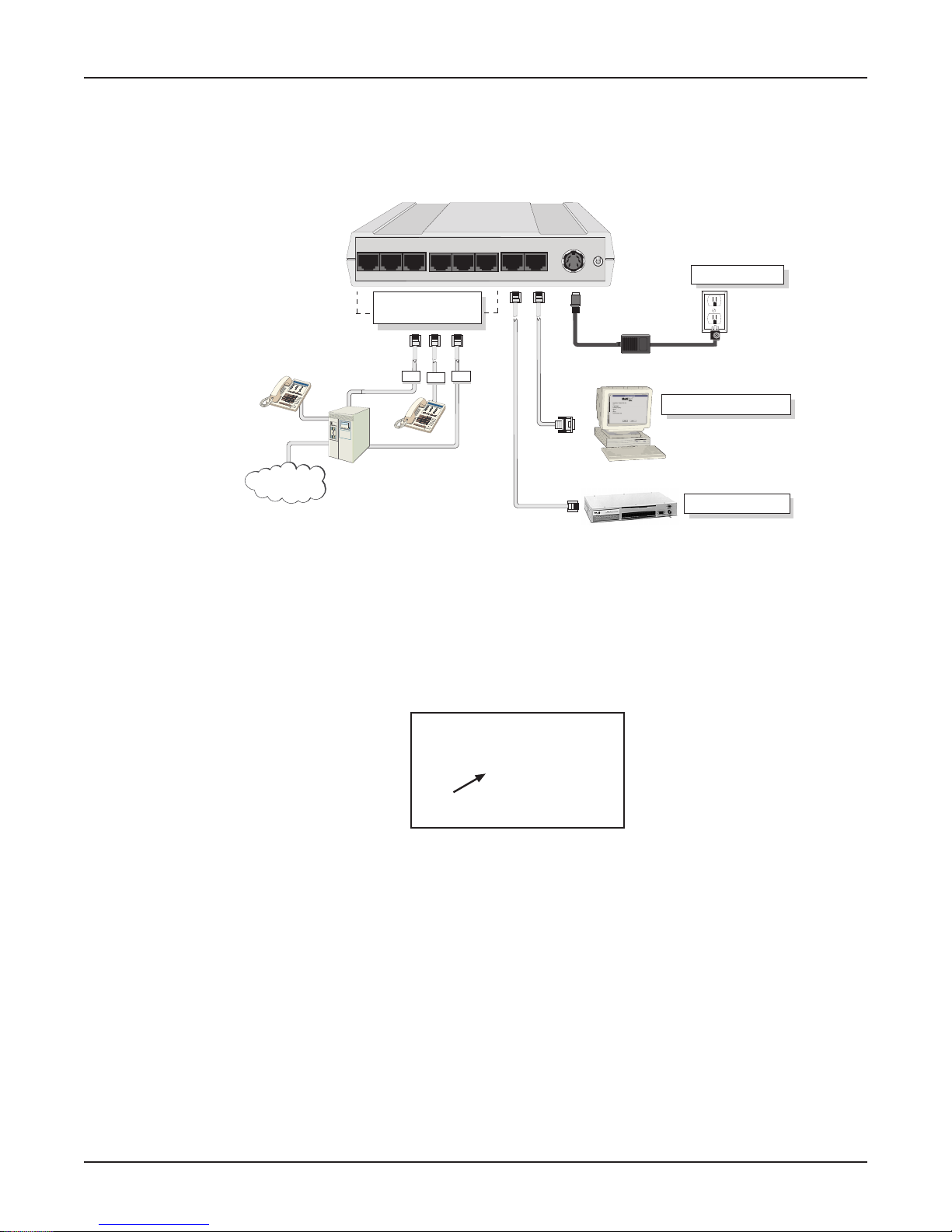
Cabling Y our MultiVOIP 200
Cabling your MultiVOIP 200 involves making the proper Power, Command Port, and Internet
connections. Figure 2-2 shows the back panel connectors and the associated cable connections. The
Cabling Procedure section provides step-by-step instructions for cabling your MultiVOIP 200.
PSTN
Voice/Fax Channel 1
E&M FXS FXO
Voice/Fax Channel
1 & 2 Connections
E&M FXO
PBX
Voice/Fax Channel 2
FXO FXS E&M
FXS
Ethernet RS232
Command
10Base-T
Power
1
0
Power Connection
Command Port Connection
Network Connection
Hub
Figure 2-2. Cable Connections
Note: Before cabling your MultiVOIP 200, perform the E&M Jumper Block Positioning Procedure if
either voice/fax channel (1 or 2) will be connected to an E&M trunk that is a Type 1,3, 4, or 5 rather
than a Type 2 (the default).
Caution: All MultiVOIP’s require +5 volts, +12 volts, and -12 volts while some other Multi-Tech
products only require +5V and +12 volts. You might even consider marking or labeling them to ensure
that they are kept together.
ITE POWER SUPPLY
INPUT:100-250V~50-60HZ 0.9A
OUTPUT:= 5V 3.0A
12V 0.5A
-12V 0.2A
Cabling Procedure
1. Using the supplied cable, connect the power supply to a live AC outlet, then plug the power
supply into the MultiVOIP 200 as shown in Figure 2-2. The power connector is a 6-pin circular
DIN connector.
2. Connect the MultiVOIP 200 to a PC using the RJ-45 to DB9 (female) cable provided with your
unit. Plug the RJ-45 end of the cable into the Command port of the MultiVOIP 200 and connect
the other end to the PC’s serial port. See Figure 2-2.
3. Connect a network cable to the Ethernet 10Base-T connector on the back of the MultiVOIP 200.
Connect the other end of the cable to your network.
4. If you are connecting a station device; e.g., analog telephone, fax machine, or Key Telephone
System (KTS) to your MultiVOIP 200, connect the smaller end of a special adapter cable
(supplied) to the Voice/Fax Channel 1 FXS connector on the back of the MultiVOIP 200 and the
other end to the station device.
20
Page 21

Chapter 2 - Installation
If you are connecting a PBX extension to your MultiVOIP 200, connect the smaller end of a
special adapter cable (supplied) to the Voice/Fax Channel 1 FXO connector on the back of the
MultiVOIP 200 and the other end to the PBX extension.
If you are connecting an E&M trunk from a telephone switch to your MultiVOIP 200, connect one
end of an RJ-45 cable (not supplied) to the Voice/Fax Channel 1 E&M connector on the back of
the MultiVOIP 200 and the other end (8 spade lugs or 8 wires to connect directly to the punchdown block) to the PBX trunk card.
If you are using a Magix 400 E&M Tie Card, connect the ground pin to the chassis ground screw
as shown.
MVP 200
Connection
M INPUT
E OUTPUT
T1 4-WIRE OUTPUT
R 4-WIRE INPUT, 2-WIRE
T 4-WIRE INPUT, 2-WIRE
R1 4-WIRE OUTPUT
SG (SIGNAL GND) OUTPUT
SB (SIGNAL BATTERY OUTPUT
PIN NO.
1
2
3
4
5
6
7
8
Magix 400 E&M 4
Wire Tire Card
PIN NO.
M MOUTH CONTROL
6
E EAR CONTROL
3
T1 TIP 1 RECEIVE
1
R RING TRANSMIT
4
T TIP TRANSMIT
5
R1 RING 1 RECEIVE
2
CHASSIS GROUND SCREW
UNUSED
Male Male
Note: For customers building their own E&M connector, Appendix B has a pinout diagram
showing the E&M back panel connector on the MultiVOIP 200.
5. Repeat step 4 to connect the remaining telephone equipment to each Voice/Fax Channel on your
MultiVOIP 200.
6. Turn on power to the MultiVOIP 200 by setting the power switch on the back panel to the 1 (up,
On) position. Wait for the Boot LED on the MultiVOIP 200 to go Off before proceeding. This may
take a couple of minutes.
If you need to change the E&M Jumper Block positioning, refer to the following section; otherwise,
proceed to the Chapter 3, Software Loading and Configuration, to load the MultiVOIP 200 software.
21
Page 22
MultiVOIP 200 User Guide
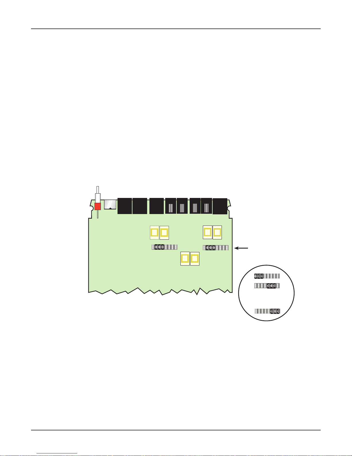
E&M Jumper Block Positioning Procedure
Each voice/fax channel on the MultiVOIP 200 has a separate E&M jumper block located near the
jacks on the back panel of the MultiVOIP 200. Each jumper block has 8 pairs of pins with a jumper
plug on three adjacent pairs of pins. The jumper plug must be centered on the E&M type number
(see Figure 2-3) that matches the E&M connection for that channel.
MultiVOIP 200’s shipped to Europe, Great Britain, and Ireland have the default setting for the E&M
jumper blocks defaulted to a type 5.
Perform the following procedure if you need to move the E&M jumper block from its default (Type 2)
for North America or the default type 5 for international markets.
1. Ensure that the external power supply is disconnected from the MultiVOIP 200.
2. Turn the MultiVOIP 200 upside down and remove the cabinet mounting screw at the center back
of the cabinet.
3. Return the MultiVOIP 200 to its upright position, then slide the base out the rear of the cabinet.
Note: To change a jumper position, lift the jumper plug up off the jumper block, then move it to
the new position, ensuring that the middle jumper of the jumper block is centered on the E&M
type number (1,3; 4; or 5) as shown on Figure 2-3. (Note: Numbers are
not
on the board.)
Back Panel Connectors
2
Channel 2
2
Channel 1
Jumper Blocks
In Position 2
(Default)
1,3
4
Alternate Positions
Note: Markings do not appear on board.
5
Figure 2-3. E&M Jumper Block Positions
4. Change the jumper block position for any voice/fax channel to be connected to an E&M trunk that
is not a Type 2 (the default position).
5. Slide the base all the way into the cabinet until it stops.
6. Turn the MultiVOIP 200 upside down and replace the cabinet mounting screw that was removed
in step 2.
7. Return the MultiVOIP 200 to its upright position, then perform the cabling procedure.
22
Page 23

Voice / Fax over IP Networks
Chapter 3 - Software Loading and Configuration
Page 24
MultiVOIP 200 User Guide
Installing Your MultiVOIP 200 Software
The following installation procedures do not provide every screen or option in the process of installing
the MultiVOIP 200 software. It is assumed that a technical person with a thorough knowledge of
Windows and the software loading process is doing the installation. Once you have installed the
software, you will be instructed on how to configure your MultiVOIP 200, and finally, on how to deploy
your MultiVOIP 200. Additional information on the MultiVOIP 200 software is provided in Chapter 4,
MultiVOIP 200 Software, and in the on-line Help.
Note: The phonebook directory configuration process is different depending on whether or not you
have an enabled H.323 Gatekeeper resident in your network. The section on “Configuring Your
MultiVOIP 200” will explain these differences.
If your network includes a Multi-Tech Gatekeeper, Gateways, or other third-party VOIP Gateways or
endpoints that support H.323 (for example, Microsoft NetMeeting), you will likely want to install H.323
software.
The MultiVOIP 200 software, Quick Start, and User Guide are contained on the MultiVOIP 200 CD.
The CD is auto-detectable, so when you insert it into your CD ROM drive it will start up automatically.
When you have finished configuring your MultiVOIP 200, you can view and print the User Guide by
clicking on the View Manuals icon and selecting either the Quick Start or this User Guide.
CAUTION: If you are installing a MultiVOIP 200 behind a Firewall, the Firewall must support H.323.
Refer to your Firewall user documentation to enable H.323 support.
1. Make certain that your MultiVOIP 200 has been properly cabled and that it is powered on.
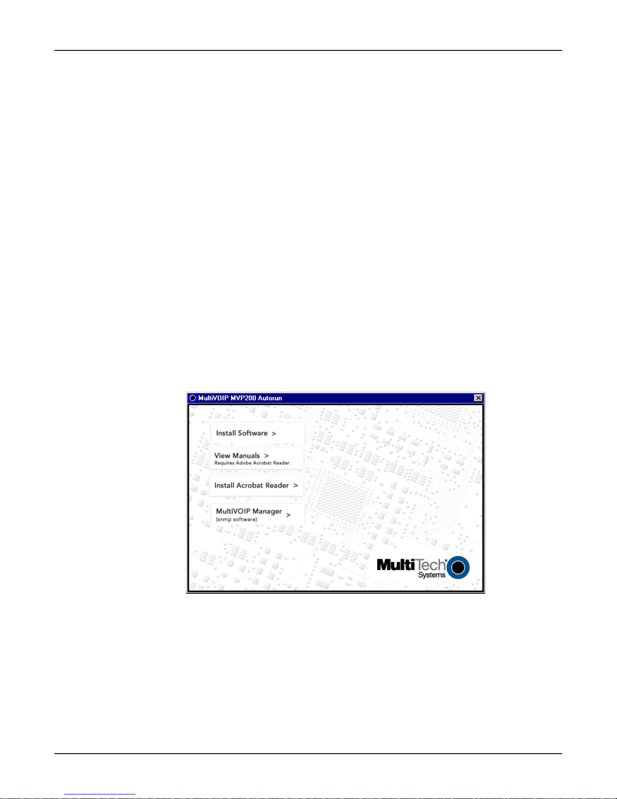
2. Insert the MultiVOIP 200 CD into a CD-ROM drive. The CD is auto-detectable, so it starts
automatically. It may take 10 to 20 seconds for the Multi-Tech Installation CD screen to appear.
If the Multi-Tech Installation CD Screen does not appear automatically, click My Computer, then
right-click the CD-ROM drive icon, click Open, then click the Autorun icon.
3. When the Multi-Tech Installation CD Screen is displayed, click the Install Software icon and
choose H.323 compatible from the Select Software dialog box.
24
Page 25
Chapter 3 - Software Loading and Configuration
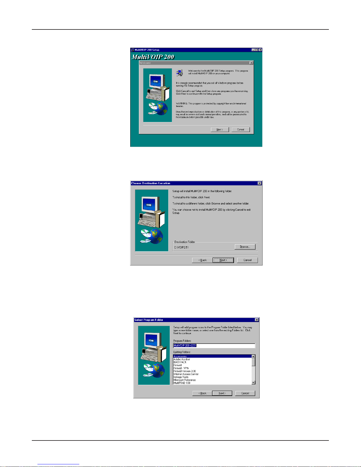
4. The MultiVOIP 200 Setup welcome screen is displayed.
Press Enter or click Next> to continue.
5. The Choose Destination Location dialog box is displayed. Follow the on-screen instructions.
You can either choose the Destination Location of your MultiVOIP 200 software or select the
default destination by clicking Next>. If you click Browse, you can select a different destination
folder for the MultiVOIP 200 software.
6. The Select Program Folder dialog box enables you to choose where you want the program file
to be located.
Verify the path and click Next > to continue.
25
Page 26
MultiVOIP 200 User Guide
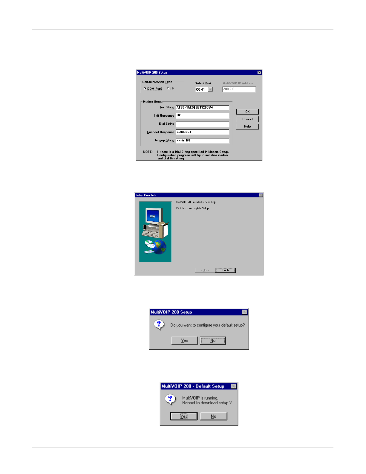
7. The Copying program files ... screen is displayed followed by the MultiVOIP 200 Setup
dialog box. This dialog box enables you to select the COM port of your PC that is connected to the
Command port of the MultiVOIP 200. From the Select Port drop-down list, choose the COM port
of your PC.
Click OK to continue.
8. The Setup Complete dialog is displayed.
26
Click Finish to continue.
9. The following message is displayed:
Click Yes to continue.
10. The following message is displayed.
Click Yes to continue.
Page 27
Chapter 3 - Software Loading and Configuration
Configuring Your MultiVOIP 200
The following steps provide instructions for configuring your MultiVOIP 200. The configuration sequence includes
IP Protocol default setup, Channel setup, and Phone Directory Database setup. The Phone Directory Database
setup is configured differently depending on whether or not the Gatekeeper function is available and enabled on
the Phone Directory Database dialog box (See Step 26).
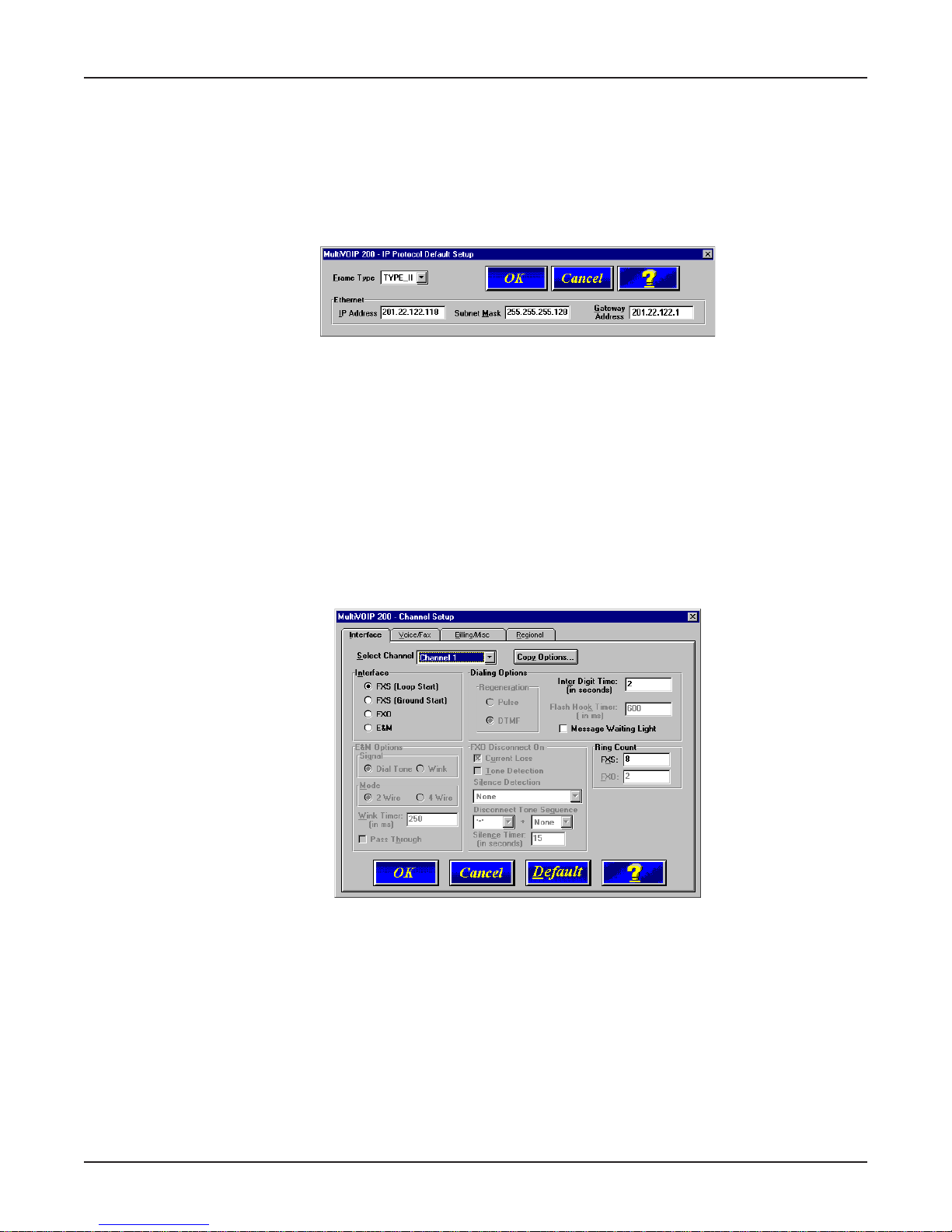
11. The IP Protocol Default Setup dialog box is displayed.
The default Frame T ype is TYPE_II. If this does not match your IP network, change the Frame
Type by clicking the drop-down arrow and selecting SNAP. The available Frame Type choices are
TYPE_II and SNAP.
12. In the Ethernet group, enter the IP Address, Subnet Mask, and Gatewa y Address unique to
your IP LAN in the corresponding fields.
The IP address is the unique LAN IP address that is assigned to the MultiVOIP 200, and the
Gateway address is the IP address of the device connecting your MultiVOIP 200 to the Internet.
Click OK when you are finished.
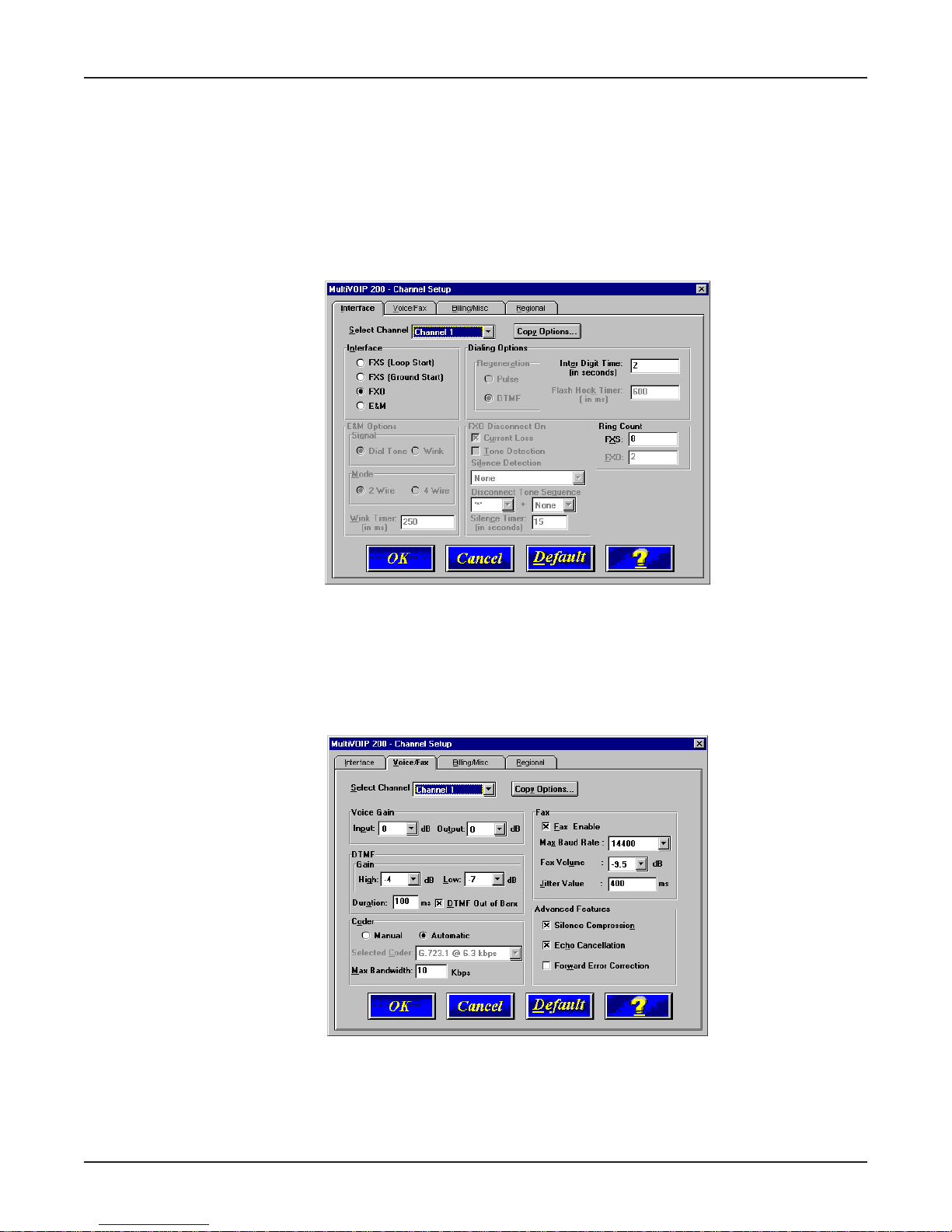
13. The Channel Setup dialog box is displayed. The four tabs in this dialog box define the channel
interface, voice/fax parameters, billing/miscellaneous parameters, and regional telephone
parameters for each channel.
Configure each channel for the type of interface you are connecting to. The Interface tab defaults
to Channel 1 in the Select Channel field. To change the channel number, click the drop-down
arrow and the list of channels is displayed. Highlight the channel you want to configure.
Note: Feature options are enabled or disabled (grayed out) according to the interface type that
you select. The one option available for all interface types is the Inter Digit Time option. This
option defines the maximum amount of time that the unit will wait before mapping the dialed digits
to an entry in the Phone Directory Database. If too much time elapses between digits, and the
wrong numbers are mapped, you will hear a rapid busy signal. If this happens, it will be
necessary to hang up and dial again. The default setting is 2 seconds.
27
Page 28

MultiVOIP 200 User Guide
14. The Interface group defaults to FXS (Loop Start). Select the interface option that corresponds
to the interface type being connected to the Voice/Fax Channel 1 jack on the back panel of the
MultiVOIP 200.
FXS (Loop Start): If a station device; e.g., an analog telephone, fax machine, or KTS (Key
Telephone System) is connected to the Voice/Fax connector on the back of the unit, FXS (Loop
Start) will likely be the correct Interface.
FXS (Ground Start): If the station device uses ground start, then choose the FXS (Ground Start)
option. Refer to the device’s user documentation.
For both FXS Loop Start and FXS Ground Start , the Ring Count FXS window allows you to set
the maximum number of rings output on the FXS interface before hanging up and releasing the
line to another call. The default setting is 8 rings.
Note: Zero (0) means no rings - caller hears a busy tone.
FXO: If you are using an analog extension from your PBX, then choose the FXO option. Check
with your in-house phone personnel to verify the connection type.
If FXO is selected, the Dialing Options Regeneration, Flash Hook Timer, and Ring Count
groups are enabled. Check with your local in-house phone personnel to verify whether your local
PBX dial signaling is Pulse or tone (DTMF). Then, set the Regeneration option accordingly. The
Flash Hook Timer allows you to enter the time, in milliseconds, for the duration of the flash hook
signals output on the FXO interface. The default setting is 600 milliseconds. The Ring Count
FXO window allows you to set the number of rings received on the FXO interface before the
MultiVOIP 200 answers the incoming call. The default setting is 2 rings.
Note: Zero (0) means that the MultiVOIP 200 never answers.
For FXO-to-FXO communications, you can enable a specific type of FXO Disconnect; Current
Loss, Tone Detection, or Silence Detection. (Check with your in-house phone personnel to
verify the preferred type of disconnect to use.) Enabling Tone Detection activates the
Disconnect Tone Sequence options. For Disconnect T one Sequence, you can select from dropdown lists either one or two tones that will cause the line to be disconnected; the person hanging
up a call must then hit the key(s) that will produce those tones. For Silence Detection, select
One Way or Two Way, then set the timer for the number of seconds of silence before disconnect.
Note that the default value of 15 seconds may be shorter than desired for your application.
E&M: If you are connecting to an analog E&M trunk on your PBX, then choose the E&M interface
option to enable the E&M Options group. Check with your local in-house phone personnel to
determine if the signaling is Dial Tone or Wink and if the connection is 2-wire or 4-wire. If Wink
signaling is used, then the Wink Timer is enabled with a default of 250 milliseconds. The range
of the Wink Timer is from 100 to 350 milliseconds. Consult with your local in-house phone
personnel for this timer setting.
Note: After configuring a given channel (1 or 2), you can copy that channel’s configuration by
clicking the Copy button and everything on the Interface tab will be copied to the other channel.
15. Repeat the above step to configure the interface type for voice/fax channel 2.
28
Page 29
Chapter 3 - Software Loading and Configuration
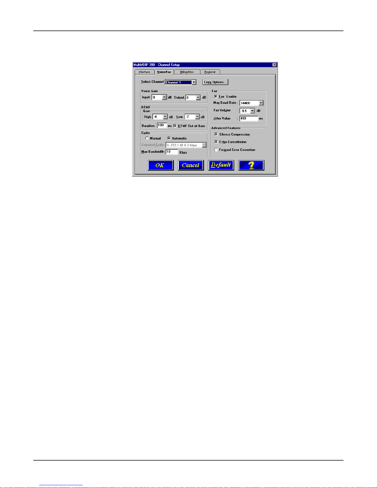
16. The Voice/Fax tab displays the parameters for the voice gain, DTMF (Dual Tone Multi-
Frequency) gain, voice coder, faxing, and advanced features such as Silence Compression,
Echo Cancellation, and Forward Error Correction.
17. You can set up the input and output voice gain so that the volume can be increased or
decreased. Input gain modifies the level of the audio coming in to the voice channel before it is
sent over the Internet to the remote MultiVOIP 200; and, output gain modifies the level of the
audio being output to the device attached to the voice channel. Make your selections from the
Input and Output drop-down lists in the Voice Gain group. The valid range is +31dB to –31dB
with a recommended/default value of 0.
You can also set up the DTMF gain (or output level in decibels - dB) for the higher and lower
frequency groups of the DTMF tone pair. Make your selections in the drop-down lists in the
DTMF Gain group. When DTMF Out of Band is checked, the unit reproduces the DTMF tones
instead of passing them through.
Note: Only change the DTMF gain under the direction of Multi-Tech Technical Support
supervision.
18. To change the voice coder, first select the channel by clicking the Select Channel down arrow
(highlighting the channel number) then click Manual in the Coder group. To select the appropriate
coder, click the Selected Coder down arrow and highlight your new voice coder entry.
If you changed the voice coder, ensure that the same voice coder is used on the voice/fax
channel you are calling; otherwise, you will always get a busy signal.
Note: If you allow the Coder to be selected automatically, then you need to select the Max
Bandwidth from the drop-down list. Check with your Network Administrator to determine how
much bandwidth is available.
19. The Fax group enables you to send/receive faxes on the selected voice/fax channel. You can set
the maximum baud rate for faxes and the fax volume in the two drop-down lists and change the
jitter value in milliseconds.
When receiving fax packets from a remote MultiVOIP 200, it is possible for individual packets to
be delayed or received out of order due to traffic conditions on the network. To compensate for
this effect, the MultiVOIP 200 uses a Jitter Buffer. The Jitter V alue field allows the MultiVOIP 200
to wait a user-definable period of time, in milliseconds, for delayed or out of order fax packets.
The range of allowable Jitter Values is 0 to 400 with a default of 400 milliseconds.
If you do not plan to send or receive faxes on a given voice/fax channel, you can disable faxes in
the Fax group.
29
Page 30
MultiVOIP 200 User Guide
20. You can enable the voice/fax advanced features by clicking (checking) the silence compression,
echo cancellation, or forward error correction options.
The Silence Compression option defines whether silence compression is enabled (checked) for
this voice channel. If silence compression is enabled, the MultiVOIP 200 will not transmit voice
packets when silence is detected, thereby reducing the amount of network bandwidth that is
being used by the voice channel.
The Echo Cancellation option defines whether echo cancellation is enabled (checked) for this
voice channel. If echo cancellation is enabled, the MultiVOIP 200 will remove echo which
improves the quality of sound.
The Forward Error Correction (FEC) option defines whether forward error correction is enabled
(checked) for this voice channel. The FEC feature allows some of the voice packets that were
corrupted (or lost) to be recovered. FEC adds an additional 50% overhead to the total network
bandwidth consumed by the voice channel.
Note: After configuring a given channel (1 or 2), you can copy that channel’s configuration by
clicking the Copy button and everything on the Voice/Fax tab will be copied to the other channel.
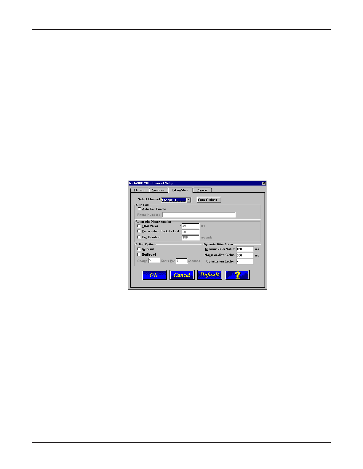
21. The Billing/Misc tab displays the parameters for auto call, automatic disconnection, billing
options, and dynamic jitter buffer.
If you want to dedicate a local voice/fax channel to a remote voice/fax channel (so you will not
have to dial the remote channel), click the Auto Call Enable option in the Auto Call group. Then
enter the phone number of the remote MultiVOIP 200 in the Phone Number field.
22. The Automatic Disconnection group provides three options to be used singly or in combination.
The Jitter Value defines the average inter-arrival packet deviation (in milliseconds) before the
call is automatically disconnected. Jitter is the inter-arrival packet deviation (phase shift of digital
pulses) over the transmission medium that causes voice breakup which can be particularly
disruptive to voice communications. The default setting is 20 milliseconds. A higher value means
that the voice transmission will be more accepting of jitter. A lower value will be less tolerant of
jitter.
Consecutive Packets Lost defines the number of consecutive packets that are lost after which
the call is automatically disconnected. The default setting is 30.
Call Duration defines the maximum length of time (in seconds) that a call remains connected
before the call is automatically disconnected. The default setting is 180 seconds. A call limit of
three minutes may be too short for most configurations. Therefore, you may want to increase this
default value.
30
Page 31

Chapter 3 - Software Loading and Configuration
23. You can set billing options for inbound and/or outbound calls by checking them in the Billing
Options group and then entering the charge in cents per number of seconds.
24. A minimum and maximum set of values can be set for Dynamic Jitter Buffer. When receiving
voice packets from a remote MultiVOIP 200, it is possible to experience varying delays between
packets due to traffic conditions on the network. This is called Jitter. To compensate for this
effect, the MultiVOIP 200 uses a Dynamic Jitter Buffer. The Jitter Buffer allows the MultiVOIP 200
to wait for delayed voice packets by automatically adjusting the length of the Jitter Buffer between
configurable minimum and maximum values. An Optimization Factor adjustment controls how
quickly the length of the Jitter Buffer is increased when jitter increases on the network. The length
of the jitter buffer directly effects the voice delay between MultiVOIP 200 gateways.
The Minimum Jitter Value default setting is 150 milliseconds, the Maximum Jitter Value default
setting is 300 milliseconds, and the Optimization Factor default setting is 7.
Note: After configuring a given channel (1 or 2), you can copy that channel’s configuration to the
other channel by clicking the Copy button. Everything on the Billing/Misc tab will be copied to
the other channel.
If your country/region is not the default USA, click the Regional tab and proceed to step 25;
otherwise, proceed to step 26 to begin building your phone directory database.
25. To change the Tone Pairs on the Regional tab, click the Country/Region down arrow and
highlight your specific country or region.
Note: If your country or region is not listed, click the Custom button to define it.
The Tone Pairs group enables you to select/modify the parameters according to choice. Click
OK when finished. Proceed to step 26 to begin building your phone directory database.
31
Page 32

MultiVOIP 200 User Guide
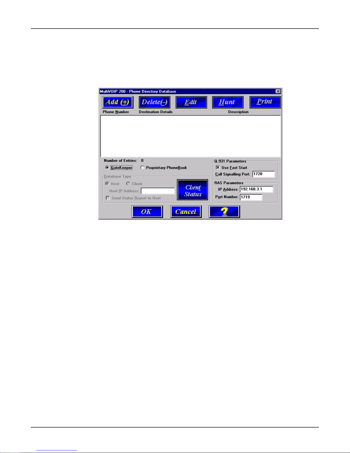
26. The Phone Directory Database dialog box is displayed with the Proprietary PhoneBook option
enabled and no phone numbers entries displayed in the database. This dialog box enables you to
select either the GateKeeper or Proprietary PhoneBook. Once you have choosen the type of
Phone Book database, you can proceed to registering with a Gatekeeper in the following section
(entitled, Registering with a Gatekeeper Phone Directory); or, if you are building a proprietary
phone book, proceed to Building a Proprietary Phonebook Directory.
(Note: Each of these sections starts with a step “27.”)
Registering with a Gatekeeper Phone Directory
This section describes how to register H.323 endpoints with the Gatekeeper. The H.323 Gatekeeper
function resides at a PC acting as the central point for all calls within its zone and providing call
control services to registered endpoints. The Gatekeeper performs two important call control
functions: address translation from LAN aliases to IP addresses, and bandwidth management where
the network manager has specified a threshold for the number of simultaneous conferences on the
LAN.
In a GateKeeper environment, you will be enabling the GateKeeper option, entering an IP address
for the GateKeeper, accepting the default port number, and if the GateKeeper network is servicing
Fast Start, accept the defaults in the Q.931 Parameters group. However, if this network zone is
primarily non-fast start supported, you will disable Use Fast Start.
27. Enable the Gatekeeper option
28. If the GateKeeper network employs Fast Start, then accept the Use Fast Start option (default).
You may have to verify this with the GateKeeper administrator.
29. Enter the Gatekeeper IP Address in the IP Address field of the RAS Parameters group.
30. Accept the default Port Number 1719.
32
Page 33

Chapter 3 - Software Loading and Configuration
CAUTION: The default setting for the Gatekeeper Port Number is 1719. This can be changed to a
different value by the Gatekeeper administrator. If you decide to change the default Port Number,
you must use the same number on the Gatekeeper and all other H.323 endpoints.
31. When you are finished with this dialog box, click the Add (+) button to begin building your phone
directory database. The Add/Edit Phone Entry dialog box is displayed.
32. Enter the unique phone number of the local device in the Phone Number field (e.g., 101).
33. Skip the Description field; i.e., leave it blank.
34. Enter the V oice Channel number corresponding to the phone number entered.
35. Fill in the H.323 ID field with a description to identify the phone number. For this example, you
could enter “New York Office 1.”
36. Enter the IP Address of the MultiVOIP you are currently configuring in the IP Address field.
37. Click OK when you are finished and the Phone Directory Database dialog box is displayed with
your first entry in the window.
38. Click the Add (+) to enter your next phone listing and the Add/Edit Phone Entry dialog box is
displayed.
33
Page 34

MultiVOIP 200 User Guide
39. Enter the second unique phone number of the local device in the Phone Number field (e.g.,
102).
40. Again, skip the Description field (leave it blank).
41. Enter the Voice Channel number corresponding to the phone number entered. (Hint: for voice
channel 2, use your mouse to select the 1, then change it to a 2.)
42. Fill in the H.323 ID field with a description to identify the phone number. For this example, you
could enter“Jerry’s Desk.”
43. Enter the IP Address of the MultiVOIP you are currently configuring in the IP Address field.
44. Click the OK button when you are finished and the Phone Directory Database dialog box is
displayed with your second entry in the window.
45. Repeat this process for all channels, then click OK on the Phone Directory Database dialog
box.
46. The following dialog box is displayed.
Click OK to download default setup.
34
Page 35

Chapter 3 - Software Loading and Configuration
47. Once the setup program receives a response from the MultiVOIP 200, the Writing Setup dialog
box is displayed indicating that the setup configuration is being written to the MultiVOIP 200.
48. After the setup has been written to the MultiVOIP 200, the unit is rebooted.
49. Check to ensure that the BOOT LED on the MultiVOIP 200 is Off after the download is complete.
This may take several minutes as the MultiVOIP 200 reboots.
50. You are returned to the Multi-Tech Installation CD screen from which you can load the Acrobat
Reader to your PC. This allows you to view and/or print the User Guide by clicking on the Install
Manuals icon.
At this time your MultiVOIP 200 is configured. Proceed to the “Deploying the VOIP Network”
section.
35
Page 36

MultiVOIP 200 User Guide
Building a Proprietary Phonebook Directory
27. To build your proprietary MultiVOIP 200 Phone Directory (i.e., in an H.323 environment without
the Gatekeeper option enabled), you will first need to enable (check) the Proprietary
Phonebook option and then configure the “Host” MultiVOIP 200 and then the “Client” MultiVOIP
200s (or other H.323 endpoints). Configuring the “Client” MultiVOIP 200 is discussed later in this
chapter.
The first MultiVOIP 200 to be configured is designated the “Host” and contains the proprietary
phonebook database. All subsequent MultiVOIP 200s added to the proprietary phonebook
database are designated “Clients.” The Host database contains the phone numbers of all H.323
endpoints available for communication on an IP network. This database is downloaded to each
Client MultiVOIP 200 as it comes on-line.
28. To configure the “Host” MultiVOIP 200, make certain that the Proprietary Phonebook and Host
options are enabled. The Client option, Host IP Address, and Send Status Report to Host will
be disabled (grayed out). The Client Status button displays the Client V OIP Status dialog box
used for viewing phone number, IP address, status, and description of Client units (See
“Configuring Your Client MultiVOIP 200s” for details). Note: In the Q.931 Parameters group, Use
Fast Start is checked for compatibility with other H.323 devices that support Fast Start Capability.
Click Add (+) to begin building your phone directory database. The Add/Edit Phone Entry dialog
box is displayed.
36
Page 37

Chapter 3 - Software Loading and Configuration
29. Enter the unique phone number of the local device in the Phone Number field (e.g., 101) and
indicate that the local device is connected to Channel 1 in the Voice Channel field.
30. The Description field is optional, but can be useful in associating the channel to the extension. If
you wish, enter a description of your local phone number. This description serves to identify the
phone number you entered in the previous step (e.g., normally the “Host” MultiVOIP 200 resides
at the entity’s main office; therefore, for this example you could enter a description such as “New
York Office 1”).
31. The Station Identification group includes a Hunt Group drop-down list. This list enables you to
indicate which Hunt Group you want the phone number to be associated with; or, you can select
NO HUNT if you don’t want this entry to participate in hunting. Hunting is a series of telephone
lines organized in such a way that if the first line is busy the next line is hunted and so on until a
free line is found. For this example, assign the phone entry to HUNT GROUP #1.
Once you have assigned this entry to a Hunt Group (or NO HUNT), you must enter the IP
Address of the Host MultiVOIP 200 in the IP Address field (e.g., 204.022.122.118).
Note: The Port field becomes active as you begin to enter the IP Address. The entry is the H.323
industry standard Port value (1720) used to communicate with other H.323 endpoints.
32. Click OK to return to the Phone Directory Database dialog box. It now includes phone number
(101), destination details (204.022.122.118 Channel 1), and description (New York Office 1).
37
Page 38

MultiVOIP 200 User Guide
33. To configure Channel 2 on the Host MultiVOIP 200, click Add (+) and the Add/Edit Phone Entry
dialog box is displayed again.
34. Enter the phone number for the MultiVOIP 200 in the Station Information group Phone Number
field (e.g., 102).
35. Click inside the Description field and enter a description for the remote MultiVOIP 200 phone
number for Channel 2. For example, “New York Office 2.”
36. In the Station Identification group, select HUNT GROUP #1 from the Hunt Group drop-down
list, enter the New York Office 2’s IP Address (204.022.122.118), and accept the H.323 industry
standard Port value (1720) used to communicate with other H.323 endpoints.
37. Click OK and you are returned to the Phone Directory Database dialog box which now includes
the second number and related information in the Phone Number list.
You have completed configuration of the “Host” MultiVOIP 200. Both voice channels belong to
Hunt Group # 1. If a call from an H.323 endpoint (a MultiVOIP 200 or a standalone H.323
endpoint) to Phone Number 101 is unable to be connected, it will automatically connect to the
next available phone number in Hunt Group #1, i.e., Phone Number 102.
38. At this point it is time to add all other phone numbers (Client units and stand-alone units) to the
Phone Directory database. To add Channel 1 of the Client MultiVOIP 200, click Add (+) and the
Add/Edit Phone Entry dialog box is displayed again.
38
Page 39

Chapter 3 - Software Loading and Configuration
39. Enter the phone number for the remote (Client) MultiVOIP 200 in the Station Information group
Phone Number field (e.g., 201).
40. Click inside the Description field and enter a description for the remote MultiVOIP 200 phone
number for Channel 1; for example, “London Office 1.”
41. In the Station Identification group, select HUNT GROUP #2 from the Hunt Group drop-down
list, enter the London Office 1’s IP Address (202.056.039.100), and accept the H.323 industry
standard Port value (1720) used to communicate with other H.323 endpoints.
42. Click OK and you are returned to the Phone Directory Database dialog box which now includes
the remote phone number and related information in the Phone Number list.
43. To add Channel 2 of the Client MultiVOIP 200, click Ad d (+) and the A dd/Edit Phone Entry
dialog box is displayed again.
44. Enter the phone number for the remote (Client) MultiVOIP 200 in the Station Information group
Phone Number field (e.g., 202).
45. Click inside the Description field and enter a description for the remote MultiVOIP 200 phone
number for Channel 2. For example, “London Office 2.”
46. In the Station Identification group, select HUNT GROUP #2 from the Hunt Group drop-down
list, enter the London Office 2’s IP Address (202.056.039.100), and accept the H.323 industry
standard Port value (1720) used to communicate with other H.323 endpoints.
39
Page 40

MultiVOIP 200 User Guide
Note: Depending on your requirements, you may want calls that cannot make a connection to
London Office 1 (Hunt Group #2) to roll over to the New York office instead. In this case, you
would configure that phone entry to be listed as a member of HUNT GROUP #1.
47. Click OK and you are returned to the Phone Directory Database dialog box which now includes
the remote phone number and related information in the Phone Number list.
48. To configure a stand-alone endpoint (e.g., a PC with NetMeeting software), click Add (+) and the
Add/Edit Phone Entry dialog box is displayed again.
49. Enter the phone number for the stand-alone endpoint in the Station Information group Phone
Number field (e.g., 301).
50. Click inside the Description field and enter a description for the remote MultiVOIP 200 phone
number. For example, “Human Resources Desk.”
Note: Because the H.323 endpoint is not a MultiVOIP 200, the Phone Directory database ignores
the Voice Channel entry, i.e., it does not matter what value is entered.
51. In the Station Identification group, select NO HUNT from the Hunt Group drop-down list, enter
the Human Resource Desk’s IP Address (e.g., 202.198.100.04), and accept the H.323 industry
standard Port value (1720) used to communicate with other H.323 endpoints.
Note: This stand-alone was not configured as part of a Hunt Group. However, depending on your
40
Page 41

Chapter 3 - Software Loading and Configuration
requirements, you could configure a stand-alone to be part of a Hunt Group.
52. Click OK and you are returned to the Phone Directory Database dialog box which now includes
the stand-alone phone number and related information in the Phone Number list.
53. When you have finished, click OK to download the setup configuration to the MultiVOIP 200.
54. The Checking MultiV OIP dialog box is displayed.
41
Page 42

MultiVOIP 200 User Guide
55. Once the setup program receives a response from the MultiVOIP 200, the Writing Setup dialog
box is displayed indicating that the setup configuration is being written to the MultiVOIP 200.
56. After the setup has been written to the MultiVOIP 200, the unit is rebooted.
57. Check to ensure that the BOOT LED on the MultiVOIP 200 is Off after the download is complete.
This may take several minutes as the MultiVOIP 200 reboots.
58. You are returned to the Multi-Tech Installation CD screen from which you can load the Acrobat
Reader to your PC. This allows you to view and/or print the User Guide by clicking on the Install
Manuals icon.
At this time your Host MultiVOIP 200 is configured. Proceed to the “Configuring Your Client
MultiVOIP 200s” section to configure the Client MultiVOIP 200(s).
42
Page 43

Chapter 3 - Software Loading and Configuration
Configuring Your Client MultiVOIP 200s
If the Proprietary Phonebook option on the Phone Directory Database dialog box was enabled,
then you will need to configure all remote H.323 endpoints as “Client” units. For example, the
MultiVOIP 200 at the company’s subsidiary office in London would need to be configured as a
“Client.”
CAUTION: If you are installing a MultiVOIP 200 behind a Firewall, the Firewall must support H.323.
Refer to your Firewall user documentation to enable H.323 support.
1. Disconnect the PC from the Command port of the Host MultiVOIP 200 and connect it to the
Command port on the Client MultiVOIP 200.
2. Fom your desktop, click Programs I MultiV OIP 200 I MultiVOIP 200 Configuration. The Main
menu is displayed.
3. Click IP to display the IP Setup dialog box.
Click (check) the Enab le Diffserv box if you have routers that support Diffserv (sometimes called
IP Precedence). This feature gives priority to voice packets so they are not delayed because of
large data files being downloaded.
The default Frame T ype is TYPE_II. If this does not match your IP network, change the Frame
Type by clicking on the drop-down arrow. The Frame Type choices are TYPE_II and SNAP.
4. In the Port Address group, enter the IP Address and IP Mask. In the Gateway Address group,
enter the gateway IP address for the Client unit.
43
Page 44

MultiVOIP 200 User Guide
The IP Address is the unique IP address that you assign to the MultiVOIP 200, and the Gateway
Address is the IP address of the device (e.g., network router) connected to the Internet/Intranet.
Click OK when you are finished. The Main menu is displayed.
5. From the Main menu, click V oice Channels to display the Channel Setup dialog box. The
Channel Setup dialog box is displayed. The four tabs in this dialog box define the channel
interface, voice/fax parameters, Billing/Misc parameters, and regional telephone parameters for
each channel.
Configure each channel for the type of interface you are connecting to. The Interface tab defaults
to Channel 1 in the Select Channel field. To change the channel number, click the drop-down
arrow and the list of channels is displayed. Highlight the channel you want to configure.
Feature options are enabled or disabled (grayed out) according to the interface type that you
select. The one option available for all interface types is the Inter Digit Time option. This option
defines the maximum amount of time that the unit will wait before mapping the dialed digits to an
entry in the Phone Directory Database. If too much time elapses between digits, and the wrong
numbers are mapped, you will hear a rapid busy signal. If this happens, it will be necessary to
hang up and dial again. The default is 2 seconds.
6. The Interface group defaults to FXS (Loop Start). Select the interface option that corresponds
to the interface type being connected to the Voice/Fax Channel 1 jack on the back panel of the
MultiVOIP 200.
FXS (Loop Start): If a station device; e.g., an analog telephone, fax machine, or KTS (Key
Telephone System) is connected to the Voice/Fax connector on the back of the unit, FXS (Loop
Start) will likely be the correct Interface option.
FXS (Ground Start): If the station device uses ground start, then choose the FXS (Ground Start)
option. Refer to the device’s user documentation.
For both FXS Loop Start and FXS Ground Start , the Ring Count FXS window allows you to set
the maximum number of rings output on the FXS interface before hanging up and releasing the
line to another call. The default setting is 8 counts.
Note: Zero (0) means no rings - caller hears a busy tone.
FXO: If you are using an analog extension from your PBX, then choose the FXO option. Check
with your in-house phone personnel to verify the connection type.
If FXO is selected, the Dialing Options Regeneration, Flash Hook Timer, and Ring Count
groups are enabled. Check with your local in-house phone personnel to verify whether your local
PBX dial signaling is Pulse or tone (DTMF). Then, set the Regeneration option accordingly. The
Flash Hook Timer allows you to enter the time, in milliseconds, for the duration of the flash hook
signals output on the FXO interface. The default setting is 600 milliseconds. The Ring Count
44
Page 45

Chapter 3 - Software Loading and Configuration
FXO window allows you to set the number of rings received on the FXO interface before the
MultiVOIP 200 answers the incoming call. The default setting is 2 counts.
Note: Zero (0) means that the MultiVOIP 200 never answers.
For FXO-to-FXO communications, you can enable a specific type of FXO Disconnect; Current
Loss, Tone Detection, or Silence Detection. (Check with your in-house phone personnel to
verify the preferred type of disconnect to use.) Enabling Tone Detection activates the
Disconnect Tone Sequence options. For Disconnect T one Sequence, you can select from dropdown lists either one or two tones that will cause the line to be disconnected; the person hanging
up a call must then hit the key(s) that will produce those tones. For Silence Detection, select
One Way or Two Way, then set the timer for the number of seconds of silence before disconnect.
Note that the default value of 15 seconds may be shorter than desired for your application.
E&M: If you are connecting to an analog E&M trunk on your PBX, then choose the E&M interface
option to enable the E&M Options group. Check with your local in-house phone personnel to
determine if the signaling is Dial Tone or Wink and if the connection is 2-wire or 4-wire. If Wink
signaling is used, then the Wink Timer is enabled with a default of 250 milliseconds. The range
of the Wink Timer is from 100 to 350 milliseconds. Consult with your local in-house phone
personnel for this timer setting.
Note: After configuring a given channel (1 or 2), you can copy that channel’s configuration by
clicking the Copy button and everything on the Interface tab will be copied to the other channel.
7. Repeat the above step to configure the interface type for voice/fax channel 2.
8. The Voice/Fax tab displays the parameters for the voice gain, DTMF (Dual Tone Multi-
Frequency) gain, voice coder, faxing, and advanced features such as Silence Compression,
Echo Cancellation, and Forward Error Correction.
9. You can set up the input and output voice gain so that the volume can be increased or
decreased. Input gain modifies the level of the audio coming in to the voice channel before it is
sent over the Internet to the remote MultiVOIP 200; and, output gain modifies the level of the
audio being output to the device attached to the voice channel. Make your selections from the
Input and Output drop-down lists in the Voice Gain group. The valid range is +31dB to –31dB
with a recommended/default value of 0.
You can also set up the DTMF gain (or output level in decibels - dB) for the higher and lower
frequency groups of the DTMF tone pair. Make your selections in the drop-down lists in the
DTMF Gain group.
Note: Only change the DTMF gain under the direction of Multi-Tech Technical Support
supervision.
45
Page 46

MultiVOIP 200 User Guide
10. To change the voice coder, first select the channel by clicking the Select Channel down arrow
(highlighting the channel number) then click Manual in the Coder group. To select the appropriate
coder, click the Selected Coder down arrow and highlight your new voice coder entry.
If you changed the voice coder, ensure that the same voice coder is used on the voice/fax
channel you are calling; otherwise, you will always get a busy signal.
Note: If you allow the Coder to be selected automatically, then you need to select the Max
Bandwidth from the drop-down list. Check with your VOIP administrator to determine how much
bandwidth is available.
11. The Fax group enables you to send/receive faxes on the selected voice/fax channel. You can set
the maximum baud rate for faxes and the fax volume in the two drop-down lists and change the
jitter value in milliseconds.
When receiving fax packets from a remote MultiVOIP 200, it is possible for individual packets to
be delayed or received out of order due to traffic conditions on the network. To compensate for
this effect, the MultiVOIP 200 uses a Jitter Buffer. The Jitter V alue field allows the MultiVOIP 200
to wait a user-definable period of time, in milliseconds, for delayed or out of order fax packets.
The range of allowable Jitter Values is 0 to 400 with a default of 400 milliseconds.
If you do not plan to send or receive faxes on a given voice/fax channel, you can disable faxes in
the Fax group.
12. You can enable the voice/fax advanced features by clicking (checking) the silence compression,
echo cancellation, or forward error correction options.
The Silence Compression option defines whether silence compression is enabled (checked) for
this voice channel. If silence compression is enabled, the MultiVOIP 200 will not transmit voice
packets when silence is detected, thereby reducing the amount of network bandwidth that is
being used by the voice channel.
This Echo Cancellation option defines whether echo cancellation is enabled (checked) for this
voice channel. If echo cancellation is enabled, the MultiVOIP 200 will remove echo-delay which
improves the quality of sound.
The Forward Error Correction (FEC) option defines whether forward error correction is enabled
(checked) for this voice channel. The FEC feature allows some of the voice packets that were
corrupted (or lost) to be recovered. FEC adds an additional 50% overhead to the total network
bandwidth consumed by the voice channel.
Note: After configuring a given channel (1 or 2), you can copy that channel’s configuration by
clicking the Copy button and everything on the Voice/Fax tab will be copied to the other channel.
The Billing/Misc tab displays the parameters for auto call, automatic disconnection, billing
options and dynamic jitter buffer.
46
Page 47

Chapter 3 - Software Loading and Configuration
13. If you want to dedicate a local voice/fax channel to a remote voice/fax channel (so you will not
have to dial the remote channel), click the Auto Call Enable option in the Auto Call group. Then
enter the phone number of the remote MultiVOIP 200 in the Phone Number field.
14. The Automatic Disconnection group provides three options to be used singly or in combination.
The Jitter Value defines the average inter-arrival packet deviation (in milliseconds) before the
call is automatically disconnected. Jitter is the inter-arrival packet deviation (phase shift of digital
pulses) over the transmission medium that causes voice breakup which can be particularly
disruptive to voice communications. The default setting is 20 milliseconds. A higher value means
that the voice transmission will be more accepting of jitter. A lower value will be less tolerant of
jitter.
Consecutive Packets Lost defines the number of consecutive packets that are lost after which
the call is automatically disconnected. The default setting is 30 packets.
Call Duration defines the maximum length of time (in seconds) that a call remains connected
before the call is automatically disconnected. The default setting is 180 seconds. A call limit of
three minutes may be too short for most configurations. Therefore, you may want to increase this
default value.
15. You can set billing options for inbound and/or outbound calls by checking them in the Billing
Options group and then entering the charge in cents per number of seconds.
16. A minimum and maximum set of values can be set for Dynamic Jitter Buffer. When receiving
voice packets from a remote MultiVOIP 200, it is possible to experience varying delays between
packets due to traffic conditions on the network. This is called Jitter. To compensate for this
effect, the MultiVOIP 200 uses a Dynamic Jitter Buffer. The Jitter Buffer allows the MultiVOIP 200
to wait for delayed voice packets by automatically adjusting the length of the Jitter Buffer between
configurable minimum and maximum values. An Optimization F actor adjustment controls how
quickly the length of the Jitter Buffer is increased when jitter increases on the network. The length
of the jitter buffer directly effects the voice delay between MultiVOIP 200 gateways.
The Minimum Jitter Value default setting is 150 milliseconds, the Maximum Jitter Value default
setting is 300 milliseconds, and the Optimization Factor default setting is 7.
Note: After configuring a given channel (1 or 2), you can copy that channel’s configuration to the
other channel by clicking the Copy button. Everything on the Billing/Misc tab will be copied to
the other channel.
If your country/region is not the default USA, click the Regional tab and proceed to step 17;
otherwise, proceed to step 18 to begin building your phone directory database.
47
Page 48

MultiVOIP 200 User Guide
17. To change the Tone Pairs on the Regional tab, click the Country/Region down arrow and
highlight your specific country or region.
Note: If your country or region is not listed, click the Custom button to define it.
The Tone Pairs group enables you to select/modify the parameters according to choice. Click
OK when finished and proceed to step 6 to begin building your phone directory database.
18. From the Main menu, click Phone Book to display the Phone Directory Database dialog box.
Make certain the Proprietary Phonebook option is enabled and in the Database Type group,
click the Client option. The Host IP Ad dress field becomes active.
Note: After you have enabled the Client option, the Client Status button is replaced by the
Update button. Once your Phone Directory database has been established, you can click this
button to refresh the entries in the Phone Directory Database window.
19. Enter the IP address (204.022.122.118) of the New York Office MultiVOIP 200 in the Host IP
Address field and enable the Send Status Report to Host so that status reports are sent to the
Host MultiVOIP 200.
Note: In a Dial-On-Demand (DOD) network, you should leave Send Status Report to Host
disabled (not checked). This allows the router to disconnect whenever there is no voice activity.
Note that Clients with Send Status Report to Host disabled will show up as “Unknown” when
viewing Client status on the Host.
20. Click OK to return to the Main menu.
48
Page 49

Chapter 3 - Software Loading and Configuration
21. Click Download Setup to write the new configuration to the Client unit. The Save Setup dialog
box is displayed.
22. Select (check) the Save Current Setup as User Default Configuration and click OK. The Writing
Setup dialog box is displayed as the setup configuration is written to the MultiVOIP 200.
After the setup is written to the MultiVOIP 200, it reboots.
23. Check that the Boot LED on the MultiVOIP 200 is off after the download is complete. This may
take several minutes as the MultiVOIP 200 reboots.
24. You are returned to the Main menu.
Your MultiVOIP 200 is operational at this time.
Repeat the process for each of the Client units. When all Clients have been configured, go
to“Deploying the VOIP Network.”
49
Page 50

MultiVOIP 200 User Guide
Deploying the VOIP Network
For a Proprietary Phone Directory database, the VOIP administrator can deploy the pre-configured Client
MultiVOIP 200s to their remote sites. The remote site administrators need only connect power to the preconfigured MultiVOIP 200, connect the MultiVOIP 200 to their Ethernet LAN and predefined telephone equipment,
and then wait for the phone directory database to be downloaded.
With the Gatekeeper option enabled on the Phone Directory Database dialog box, all MultiVOIP 200s are
configured as “Host” and cannot be downloaded. In this case, each MultiVOIP 200 Phone Book will be
programmed with phone numbers for its own channels. These phone numbers are registered with the H.323
Gatekeeper (See the “Registering with a Gatekeeper Phone Directory” section discussed earlier.
Remote Site Administrator
The following steps are for MultiVOIP 200 H.323 endpoints. For non-MultiVOIP 200 H.323 endpoints,
refer to the appropriate installation documentation.
1. Unpack your MultiVOIP 200.
2. Connect one end of the power supply to a live AC outlet and connect the other end to the Power
connection on your MultiVOIP 200 (See Figure 5).
Voice/Fax Channel
Connections
FXO
E&M
FXS
10BASET
ETHERNET
POWER
FXSE&M
FXO
PSTN
Power Connection
Ethernet Connection
Figure 5. Remote Site Cable Connection
3. Connect a network cable to the ETHERNET 10Base-T (RJ-45) connector on the back of your
MultiVOIP 200.
4. If you are connecting a station device (e.g., analog telephone, fax machine, or Key Telephone
System (KTS) to your MultiVOIP 200, connect the smaller end of a special adapter cable
(supplied) to the Voice/Fax Channel 1 FXS connector on the back of the MultiVOIP 200 and the
other end to the station device.
If you are connecting a PBX extension to your MultiVOIP 200, connect the smaller end of a
special adapter cable (supplied) to the Voice/Fax Channel 1 FXO connector on the back of the
MultiVOIP 200 and the other end to the PBX extension.
If you are connecting an E&M trunk from a telephone switch to your MultiVOIP 200, connect one
end of an RJ-45 phone cord to the Voice/Fax Channel 1 E&M connector on the back of the unit
and the other end to the trunk phone jack.
If you are connecting to an E&M trunk, you need to ensure that the E&M trunk jumper is in the
correct position for the E&M type trunk. The default E&M jumper position is E&M type 2. To
change the E&M jumper position, perform the E&M jumper block positioning procedure.
5. Repeat the above step to connect the remaining telephone equipment to each Voice/Fax
Channel on your MultiVOIP.
6. Turn on power to the MultiVOIP 200 by placing the ON/OFF switch on the back panel to the ON
position. Wait for the BOOT LED on the MultiVOIP 200 to go OFF before proceeding. This may
take a couple of minutes.
7. At this time your VOIP network should be fully operational. Dial one of the sites in your network.
50
Page 51

Voice / Fax over IP Networks
Chapter 4 - MultiVOIP 200 Software
Page 52

MultiVOIP 200 User Guide
Introduction
This chapter describes various features of the MultiVOIP 200 software that enable you to change
(update) the configuration of your MultiVOIP 200. The basic configuration parameters were
established during the loading of the software (Chapter 3). The MultiVOIP 200 software and
configuration utilities described in this chapter enable you to change that initial configuration as
necessary.
The primary interface to the MultiVOIP 200 software is the Main menu (MultiVOIP 200 Setup is on
the title bar) with individual buttons that enable you to quickly and easily select a desired function.
These features are discussed in detail in the MultiVOIP 200 Configuration section later in this
chapter.
The MultiVOIP 200 Configuration (Main menu) utility along with nine other configuration utilities
provide full software functionality for your MultiVOIP 200. Configuration Port Setup enables you to
change the method by which you access the MultiVOIP 200 (i.e., through a direct connection from a
PC to the Command Port on the MultiVOIP 200, or via your Internet or LAN connection to the LAN
port on the MultiVOIP 200). Date and Time Setup enables you to easily set the date and time used
for data logging in the MultiVOIP 200. Download Factory Defaults
configuration to the original factory settings. Download Firmware enables you to download new
versions of firmware as enhancements become available. Download User Defaults enables you to
repeat the download user defaults process (part of software installation) and update the MultiVOIP
200 configuration with any necessary changes. Download Voice Coders enables you to download
voice coders to the MultiVOIP 200 after repair or upgrade. Download H.323 Stack enables you to
download the H.323 protocols to the MultiVOIP 200 after repair or upgrade. Uninstall MultiVOIP 200
Configuration removes most of the MultiVOIP 200 software from your PC. Upgrade Software
downloads boot code, new firmware, and an H.323 file, then reboots the MultiVOIP 200.
enables you to return the
The MultiVOIP 200 software includes a context-sensitive Help system. Clicking a Help [ ? ] button
anywhere in the graphical user interface (GUI) will display definitions and recommended values for
the buttons, options, and fields on that dialog box or menu. Clicking the green underlined text in the
Helps displays a popup box of related supplementary information for that topic. Clicking the Search
button (just below the Help menu bar) displays an Index tab with a list of entries. Click an entry, then
click the Display button to display the text associated with that topic.
Before You Begin
The MultiVOIP 200 software operates in a Microsoft Windows environment. The MultiVOIP 200
program group contains icons for all the utilities described above. In Windows 98/2000/NT/XP, you
can access the individual utility programs either by clicking Start | Programs | MultiVOIP 200 |
(utility)
, or by double-clicking the utility icon in the MultiVOIP 200 program group shown here:
52
Page 53

MultiVOIP 200 Configuration
The MultiVOIP 200 Setup menu consists of 10 buttons, an Events window in the middle of the menu,
and a status bar at the bottom of the menu. The 10 buttons allow you to display and change the
voice channels and IP protocol parameters, display and manage the Phone Book listing, view
statistics and call progress, and change features such as SNMP Agent, Telnet Server, WEB Server,
and assign a MultiVOIP 200 password.
Chapter 4 - MultiVOIP Software
The Events window in the lower third of the Setup menu provides information about the boot process.
The status bar at the bottom of the Setup menu displays the current status of the unit and shows, for
example, if it is Running, the most recent date the unit was configured, the type of connection you
have to the unit, and your rights. It shows if your PC is connected directly to the command port of the
MultiVOIP 200 or is communicating with the Ethernet port. The last field on the status bar is the
Rights field which displays either Read/Write or Read only rights. The first user to communicate with
the MultiVOIP 200 has Read/Write rights that enable the user to view and/or change the configuration
of the MultiVOIP 200. Any additional users have Read Only rights and can only display the
configuration of the MultiVOIP 200 but are prohibited from changing the configuration.
53
Page 54

MultiVOIP 200 User Guide
Changing Channel Parameters
The channel parameters include the interface type and its options, voice and fax settings, billing and
security, and voice communications for the country and region in which the MultiVOIP 200 is
operating. The Channel Setup dialog box, accessed by clicking the Voice Channels button on the
Setup menu, has four tabs that display the following categories of channel information -- Interface,
Voice/Fax, Billing/Misc, and Regional.
Interface
The Interface tab defines the parameters related to the physical interface of the voice/fax channel.
Depending on the interface type selected (FXS, FXO, or E&M), other options on the interface tab will
be grayed out (become inactive) indicating that they do not apply to the selected interface. The Inter
Digit Time feature applies to all interface types.
The Inter Digit Time (in seconds) option in the Dialing Options group defines the amount of time the
MultiVOIP 200 waits between digits as they are entered by the user. If this timer expires, the
MultiVOIP 200 will immediately attempt to match the digits entered to an entry in the Phone Directory
Database. The range for this option is 2 to 100 with a default of 2.
If the interface type is FXO, the Regeneration group in the Dialing Options group defines how the
MultiVOIP 200 recreates telephone numbers that were detected at the remote end. You can select
Pulse (for rotary dial telephones) or DTMF Tone dialing (touch-tone), depending upon the dialing type
that is supported by the PBX or exchange. When FXO is the Interface, the Flash Hook Timer field is
enabled (activated) Enter the time, in milliseconds, for the duration of the flash hook signals output
on the FXO interface. The default is 600 milliseconds.
FXS Interface
The FXS Interface is used to connect telephones, fax machines, key telephone systems, etc., to the
MultiVOIP 200. In addition, you need to select either Loop Start or Ground Start. Most of the
equipment mentioned will use Loop Start which is the default.
FXO Interface
The FXO Interface is used to connect PBX extensions or central office telephone lines. You also,
need to select DTMF or Pulse dialing in the Regeneration field of the Dialing Options group. If you
are unsure of the correct selection, contact the personnel in charge of your PBX or your local
telephone company to determine whether pulse or DTMF should be used.
54
Page 55

Chapter 4 - MultiVOIP Software
E&M Interface
The E&M Interface is used to connect PBX E&M trunks. You will need to select between Dial Tone or
Wink signaling and also between 2-wire and 4-wire mode. If wink signaling is selected, the wink timer
field becomes active with a range from 100 to 350 milliseconds. Contact the personnel in charge of
your PBX to determine the proper configuration of these settings.
FXO Disconnect On
The FXO Disconnect On option applies when two MultiVOIP 200s are used in an FXO-to-FXO
configuration. When you have an FXO-to-FXO configuration, you need to determine the method of
terminating the call. Three methods of terminating the call are provided: Current Loss, Tone
Detection, or Silence Detection. Current Loss is the preferred method.
Current Loss has to be supported by your PBX or local telephone company. Current Loss
terminates the call when the PBX or local telephone company switch detects a person hanging up the
phone and opens the local circuit for a minimum of 600 milliseconds.
T one Detection terminates the call when the party who wishes to disconnect enters a one or two
digit sequence on the telephone keypad. Valid digits are zero to nine, *, #, and A thru D.
Note: A through D are extended DTMF tones supported by some PBX or central office equipment
and are not the same as letters a - d on the standard telephone key pad.
Silence Detection can be silence in one direction or silence in both directions for a specified amount
of time. The amount of time is defined by the entry in the Silence Timer. The range of the Timer is
from one to 65535 seconds (roughly 18 hours). The default is 15 seconds.
Ring Count
This field enables you to enter the maximum number of rings output on the FXS interface (default is
8) before hanging up and releasing the line to another call or the number of rings (default is 2) that
must be received before the FXO port answers an incoming call.
A setting of 0 (zero) on the FXS interface disables the generation of rings. The caller will receive a
“Busy” tone.
A setting of 0 (zero) on the FXO interface causes the FXO port to ignore rings from the attached PBX
or exchange, disabling access to the MultiVOIP 200.
55
Page 56

MultiVOIP 200 User Guide
Voice/Fax
The Voice/Fax tab controls voice and DTMF gain, voice coder, fax settings, and advanced options.
The Voice Gain group enables you to select the Input and Output voice gain. Gain is the increased
signaling power that occurs as the signal is boosted by the MultiVOIP 200. The Input Gain drop-down
list defines the input gain for this voice channel. Before your MultiVOIP 200 digitizes voice, the volume
can be increased or decreased. Input gain modifies the level of the audio coming in to the voice
channel before it is sent over the Internet to the remote MultiVOIP 200. The valid range for this option
is +31dB to –31dB. The recommended and default value is 0. The Output Gain drop-down list defines
the voice output gain for this voice channel. Before your MultiVOIP 200 converts digital voice back to
analog, the volume can be increased or decreased. The output gain modifies the level of the audio
being output to the device attached to the voice channel. The valid range for this option is +31dB to –
31dB. The recommended and default value is 0.
The DTMF Gain (Dual Tone Multi-Frequency) group controls the volume level of the digital tones sent
out for Touchtone dialing. The Gain High and Gain Low fields control the gain in dB (decibels) of the
High and Low tones in the tone pairs; the default gain values are -4 dB and -7 dB, respectively. DTMF
Gain should not be changed except under supervision of MultiTech’s Technical Support.
The function DTMF Out of Band is checked (enabled) so the MultiVOIP 200 will reproduce the DTMF
tones rather than passing them through from the input to the output.
The MultiVOIP 200 supports many state-of-the art ITU (International Telecommunications Union)
voice coders. The Voice Coder drop-down menu enables you to select from a range of coders with
specific bandwidths. The higher the bps rate, the more bandwidth is used. The channel that you are
calling has to have the same voice coder selected; otherwise, you will always get a Busy signal.
The Fax group enables a fax machine to transmit and receive faxes through the MultiVOIP 200. If a
fax machine is connected to one of the voice/fax channels, the Max Baud Rate should be set to
match the baud rate of the fax machine (refer to user documentation). The Fax V olume setting
controls the output level of the fax tones, and this setting should be changed only under the direction
of Multi-Tech’s Technical Support personnel (see Chapter 6 - Warranty, Service and Tech Support).
The Jitter V alue setting defines the inter-arrival packet deviation (in milliseconds) for the fax
transmission. A higher value will increase the amount of delay (allowing for a higher percentage of
packets to be reassembled) and a lower value would decrease the amount of delay (a lower
percentage of packets would be reassembled).
56
Page 57

Chapter 4 - MultiVOIP Software
The Advanced Features group allows you to enable Silence Compression so that a MultiVOIP 200
will not transmit voice packets when silence is detected, thereby reducing the amount of network
bandwidth that is being used by the voice channel; Echo Cancellation for a particular voice channel
will remove echo and improve the quality of sound; and, Forward Error Correction allowing some of
the voice packets that were corrupted (or lost) to be recovered. FEC adds an additional 50%
overhead to the total network bandwidth consumed by the voice channel.
Billing/Misc
This tab controls the parameters for auto call, automatic disconnection, billing options, and dynamic
jitter buffer.
The Auto Call option allows the local MultiVOIP 200 to call a remote MultiVOIP 200 without the user
having to dial a Phone Directory Database number. As soon as you access the local MultiVOIP 200
voice/fax channel, the MultiVOIP 200 immediately connects to the remote MultiVOIP 200 that you
identified in the Remote MultiVOIP 200 Phone Number field of this option.
The Automatic Disconnection group provides three options which can be used singly or in any
combination. The Jitter Value defines the average inter-arrival packet deviation (in milliseconds)
before the call is automatically disconnected.The default is 20 milliseconds. A higher value means
voice transmission will be more accepting of jitter. A lower value is less tolerant of jitter.
Consecutive Packets Lost defines the number of consecutive packets that are lost after which the
call is automatically disconnected. The default is 30 packets.
Call Duration defines the maximum length of time (in seconds) that a call remains connected before
the call is automatically disconnected. The default is 180 seconds. A call limit of three minutes may
be too short for most configurations. Therefore, you may want to increase this default value.
Billing Options can be used to track the cost of Inbound and/or Outbound calls on any of the three
interfaces (FXO, FXS, or E&M). The amount to be charged in cents is entered in the Charge ( )
Cents field together with the associated time duration in the Per ( ) Seconds field. While a given
call is active, the accumulated charges can then be viewed on the Call Progress dialog box. When
the call ends, the charges are transferred to a Log File that can be viewed by highlighting the call
event in the Log Entries dialog box and selecting Details.
Dynamic Jitter Buffer defines a minimum and a maximum jitter value for voice communications.
When receiving voice packets from a remote MultiVOIP 200, it is possible to experience varying
delays between packets due to traffic conditions on the network. This is called Jitter. To compensate
for this effect, the MultiVOIP 200 uses a Dynamic Jitter Buffer. The Jitter Buffer allows the MultiVOIP
200 to wait for delayed voice packets by automatically adjusting the length of the Jitter Buffer
57
Page 58

MultiVOIP 200 User Guide
between configurable minimum and maximum values. An Optimization Factor adjustment controls
how quickly the length of the Jitter Buffer is increased when jitter increases on the network. The
length of the jitter buffer directly effects the voice delay between MultiVOIP 200 gateways.
The default minimum dynamic jitter buffer of 150 milliseconds is the minimum delay that would be
acceptable over a low jitter network. The default maximum dynamic jitter buffer of 300 milliseconds is
the maximum delay tolerable over a high jitter network.
The Optimization Factor determines how quickly the length of the Dynamic Jitter Buffer is changed
based on actual jitter encountered on the network. Selecting the minimum value of 0 means low voice
delay is desired, but increases the possibility of jitter induced voice quality problems. Selecting the
maximum value of 12 means highest voice quality under jitter conditions is desired at the cost of
increased voice delay.
The Optimization Factor can be configured in the range of 0 to 12 with a default setting of 7.
Regional
The Regional tab controls the voice communications for the country or region in which the MultiVOIP
200 is being used.
From the Country/Region drop-down list you can select the country or region for which you are
configuring the MultiVOIP 200. The Tone Pairs group always displays the tones used in the country
or region currently selected. In addition to Australia, Central America, Chile, Europe, France, Japan,
UK, and USA, there is a Custom selection (with defaults identical to USA) that will make the Custom
button active. Clicking the Custom button enables you to edit the Tone Pairs and establish custom
sets of tone pairs for Dial Tone, Ring, and Busy on a Custom T one P air Settings dialog box.
The Pulse Generation Ratio group contains two ratios: the 60/40 is for the USA, and the 67/33 ratio
is for international applications.
58
Page 59

Changing the Phone Directory Database
The MultiVOIP provides two phone directory database architectures; the propreitary database and a
database using an H.323 protocol gatekeeper that provides a centralized call control center. The
proprietary database is used when all the end points in the VOIP network are Multi-Tech VOIP
products. The gatekeeper centralized call control center establishes the phone directory database
when all VOIP gateways and endpoints support the H.323 protocol. The proprietary database is
based on a Host and Client relationship in which the Host VOIP maintains the phone directory
database and distributes it to its Client VOIPs. The centralized call center establishes call control, call
routing, address translation from LAN aliases to IP addresses, and bandwidth management. The
H.323 protocol allows other third party gateways and end points that support the H.323 protocol
standards to participate in the VOIP network (e.g., Microsoft NetMetting®).
Chapter 4 - MultiVOIP Software
The database displays the phone numbers in numerical order with destination details (i.e., IP Address
or H323 ID), channel assignment, and a brief description of the entry (e.g., New York Office 1). The
method for changing the phone directory database is dependent on whether the Gatekeeper option
or the Proprietary Phonebook option is enabled.
If the GateKeeper option is enabled, the RAS Parameters group is enabled and the IP address of the
GateKeeper needs to be enterred in the IP Address window. The Port Number is the port on the
GateKeeper which it communicates with its endpoints. The Q.931 Parameters group is enabled in
both the GateKeeper and Proprietary Phone Book Database architectures. The Use Fast Start
option is used when the VOIP network supports Fast Start capability.
In the GateKeeper phone directory database, the phone directory database is developed through the
Add/Edit Phone Entry dialog box. The Add/Edit Phone Entry dialog box defines the Station
Information, phone number and voice channel of the unit, and station identification, H323 ID which
defines the LAN alias and the IP address of the local unit. In the GateKeeper phone directory
database, only the phone entries of the local unit are displayed.
If the Proprietary PhoneBook option is enabled, the Database Type group is active which defines
the Host and Client relationship. If the database type is Host, then the Add (+), Delete (-), Edit, Hunt,
and Print buttons at the top of the database dialog box are active. This allows the Host database to
establish the phone directory. The Client Status button also becomes active in which you can view
the active status of all the Client units.
If the database type is set to Host, the phone directory database is developed through the Add/Edit
Phone Entry dialog box. The Add/Edit Phone Entry dialog box for the Proprietary PhoneBook defines
the Station Information of the MultiVOIP, that is the phone number, description, and voice channel of
the unit, and the station identification, that is if a hunt group is employed and IP address of the unit.
This information is presented in the Phone Directory Database dialog box.
59
Page 60

MultiVOIP 200 User Guide
If the database type is set to Client, then the IP address of the Host MultiVOIP needs to be enterred
in the Host IP Address window, the Send Status Report to Host option can be enabled, and all the
buttons at the top of the directory database dialog box become inactive, except for the Print button.
Proprietary Phone Directory Database
In the Proprietary Phone Directory Database, you can add, delete, or edit any entry in the phone
directory database and you can set up Hunt groups that locate another phone phone number if the
called number is busy. You can print the phone directory database so that you have a hardcopy of the
phone directory.
To add an entry to the Phone Directory database, click on the Add (+) button and the Add/Edit Phone
Entry dialog box is displayed.
The Add/Edit Phone Entry dialog box contains two groups of information; the Station Information
which contains the phone number, an optional description window, and the voice channel number.
The Station Identification group contains the Hunt Group listing and the IP Address window for the IP
Address of the MultiVOIP assigned the phone number. The Port number is not used in the
proprietary phone book. The Copy From button in the Add/Edit Phone Entry dialog box makes it easy
to add additional phone entries.
The Station Information identifies the calling unit by the phone number, a description if you choose,
and voice channel of the unit doing the calling. The Phone Number does not have to be a
conventional telephone number like 717-5565. It can be a for example a three digit number like 101.
The Description window is like your name in your local telephone book listing. It identifies who the
calling party is, e.g., New York Office 1 or Jerry’s Desk. The voice channel window defines the voice
channel associated with the telephone.
The Station Identification group enables you to assign the entry to a Hunt Group, provide the IP
60
Page 61

Chapter 4 - MultiVOIP Software
Address of the MultiVOIP being assigned the phone number, and accept the H.323 industry standard
Port number. A Hunt Group is a series of telephone lines organized in such a way that if the first line
is busy the next line is hunted and so on until a free line is found. It is a set of links which provides a
common resource and which is assigned a single hunt group designation. A user requesting that
designation may then be connected to any member of the Hunt Group.
You can view the details of the current Hunt Group (e.g., HUNT GROUP #1) configuration by clicking
on the Phone Directory Database’s Hunt button. The current Phone numbers for HUNT GROUP #1
are displayed.
Highlight the Hunt Group you wish to view. The Phone no’ s window displays the telephone numbers
associated with that Hunt Group and the No. of Entries field displays the running total of entries.
Note: You can change the name of the Hunt Group by clicking on the entry that you want to change,
editing the change in the Hunt Group name window, and then clicking the Set button.
The Client Status button on the Phone Directory Database dialog box allows you to view the status
of all the Client units in your VOIP network (Send Status Report to Host must be enabled on the
Client). The Phone Number of each Client is displayed with its IP Address, current line status, and
the description of the phone number.
The Proprietary Phone Directory Database with the Host MultiVOIP assigned phone numbers 101
and 102 in the New York Office and a Client unit with phone numbers 201 and 202 in the London
Office. A third Client unit has phone number 301 in the following Phone Directory Database dialog
box.
61
Page 62

MultiVOIP 200 User Guide
This Phone Directory Database will be displayed on each Client unit in the VOIP network serviced by
the Host VOIP. When a Client unit comes on line, the database directory is down loaded to the unit.
So each VOIP in the network can see and call any other VOIP in the network. Only the Host VOIP
can change the phone number entries.
Gatekeeper Phone Directory Database
With the Gatekeeper Phone Directory Database, the Gatekeeper acts as the central point for all
calls within its zone and provides call control services to registered endpoints. The Gatekeeper
performs address translation from LAN aliases to IP addresses and provides bandwidth management
where the network manager has specified a threshold for the number of simultaneous calls on the
LAN.
62
Page 63

Chapter 4 - MultiVOIP Software
When the Gatekeeper Phone Directory Database option is enabled, the RAS Parameters group is
enabled with the IP address of the Gatekeeper displayed in the IP Address field. The Port Number is
the port of the endpoint communicating with the Gatekeeper. If this number is changed, it should only
be changed with consultation with Gatekeeper administrator. The port numbers have to be in pairs
and controlled by the Gatekeeper.
If the H.323 Gatekeeper network supports Q.931 Fast Start servicing, then the Use Fast Start option
on all endpoints should be enabled. The Call Signalling Port of 1720 is the port on the MultiVOIP unit
supporting the Q.931 parameters.
The Phone Directory Database in a H.323 Gatekeeper network only displays the station information
and station identification of the local unit. The station information and identification have to be
established in conjunction with the Gatekeeper administrator so that the identification of the endpoint
is the same. To add an entry to the Phone Directory Database, click on the Add (+) button and the
Add/Edit Phone Entry dialog box is displayed.
The Add/Edit Phone Entry dialog box contains two groups of information; the Station Information
which contains the phone number, description window which can be left blank, and the voice channel
number. The Station Identification group contains the H.323 ID and the IP Address window for the IP
Address of the MultiVOIP assigned the phone number. The Port number of the MultiVOIP unit
communicating with the Gatekeeper. This port number has to match the port number pair used by
the Gatekeeper. If the port number on either end is changed, communication between endpoint and
the Gatekeeper is lost. The Copy From button in the Add/Edit Phone Entry dialog box makes it easy
to add additional phone entries.
The Station Information identifies the calling unit by the phone number, a description if you choose,
and voice channel of the unit doing the calling. The Phone Number does not have to be a
conventional telephone number like 717-5565. It can be a for example a three digit number like 101.
The Description window and the H323 ID window may contain the same information. It is
recommended that the Description window be left blank and the identifying information be enterred in
the H323 ID window. The voice channel window defines the voice channel associated with the
telephone.
63
Page 64

MultiVOIP 200 User Guide
The Station Identification group allows you to define the MultiVOIP unit by establishing the H323 ID
which can be the same as for example your name in your local telephone book listing. The
Gatekeeper associates the H323 ID with the address of the local unit in the IP Address window. The
Port number 1720 is the port of the MultiVOIP communicating with the Gatekeeper.
The Station Information and Identification of the MultiVOIP unit have to be identical the same type of
information used by the Gatekeeper in order for the MultiVOIP unit to be registered with the
Gatekeeper. The Gatekeeper can allow an open registration or a secure registration in which the
endpoints are pre-defined by the Gatekeeper. The registration method is determined by the
Gatekeeper administrator and will require communication with each endpoint in order to develop the
H.323 compatiable network.
The Phone Directory Database for the local unit contains the local phone numbers, destination details
of the IP address, port number, and channel number of the local unit. The description is the same as
the entry in the H323 ID entry in the Add/Edit Phone Entry dialog box.
64
Page 65

Changing IP Parameters
The IP Setup dialog box establishes the IP addressing for the local Ethernet LAN and defines the
Internet gateway address. The IP Setup dialog box is accessed by clicking the IP button on the
MultiVOIP 200 Setup menu.
Chapter 4 - MultiVOIP Software
With IP Setup dialog box displayed you can change the status of differential services, the Ethernet
Frame Type, the IP address and IP Mask of your H.323 endpoint, and the Gateway Address of the IP
address of the device connected to the Internet.
Clicking (checking) the Enable Diffserv box enables Differentiated Services (default is disabled).
Differentiated Services provides priority to voice packets so that they are not delayed whenever large
data files need to be downloaded. You will need to check with your systems administrator to
determine if any routers in the VOIP network support this feature. If the answer is yes, then you would
want to enable this function.
The Frame Type drop-down list enables you to change the Ethernet Frame Type so that it matches
your IP network. If the current entry does not match your IP network, change the Frame Type by
clicking the drop-down arrow. The Frame Type choices are TYPE_II and SNAP.
The Port Address group enables you to change the unique IP Address and IP Mask of the local
LAN.
The Gateway Address group enables you to change the gateway IP Address of the device
connected to the Internet/Intranet.
65
Page 66

MultiVOIP 200 User Guide
Viewing Call Progress
The Call Progress dialog box is a read-only screen that displays the status of a call in progress. This
dialog box is accessed from the MultiVOIP 200 Setup menu by clicking the Call Progress button.
The ratio of Packets Lost versus Packets Received provides a general indication of the integrity of
the Internet connection. To reduce the frequency of lost packets, select a low-bit-rate coder, such as,
G.723 or Netcoder. In addition, enabling the Forward Error Correction option on the Voice/Fax tab on
the Channel Setup dialog box will enable the MultiVOIP 200 to recover many of the lost packets.
The Jitter value (measured in milliseconds) indicates the mean deviation of the difference in packet
spacing at the receiver compared to the sender for a pair of packets.
66
Page 67

Applications Setup
Clicking the Others button on the Setup menu displays the Applications Setup dialog box. This
dialog box allows you to enable SNMP Agent (the default is
parameters; enable or disable various remote configuration methods such as TFTP (Trivial File
Transfer Protocol) Server, Web Server, Dumb Terminal Management, and Telnet Server; and assign a
Password to the MultiVOIP 200 for Internet security. These applications enable remote viewing and
changing of the MultiVOIP 200 configuration, or updating firmware, from anywhere on the connected
internetwork.
Verify that the desired applications are enabled (checked). The default condition is all applications are
checked. To disable a given application, click to uncheck the check box and disable support.
SNMP related operations can be performed only when the SNMP Agent is enabled (checked) on this
dialog box. The IP address of the system (i.e., SNMP Manager) that will receive the Traps from the
MultiVOIP 200 should be entered in the IP Address field in the Trap Manager group. The Community
Name of the SNMP Manager receiving the Traps can be a maximum of 19 characters and is case
sensitive. The default Port Number of the SNMP Manager receiving the Traps is 162. The MultiVOIP
200 currently supports a maximum of two community users at a time, and they can be assigned either
Read/Write or Read Only rights. Note: if you have SNMP client software and enable SNMP Agent,
you can (in the lower right corner of the dialog box) choose to read logs through the SNMP Manager
instead of the COM port.
disabled
Chapter 4 - MultiVOIP Software
) and set up all the necessary
The Password group enables you to enter a password, up to 13 alphanumeric characters, to be used
for Internet Security. Once the password is entered (in the MultiVOIP 200 Pass wor d field) and
confirmed (in the Confirm Password field), remote users will be queried to enter the password before
gaining access to the MultiVOIP 200 for configuration purposes.
Note: If you forget your password, contact Technical Support for instructions.
For more information on using these applications, click the on-line Help button or refer to Chapter 5,
Remote Configuration and Management.
67
Page 68

MultiVOIP 200 User Guide
Viewing Statistics
The Statistics dialog box enables you to view statistics for major events of the MultiVOIP 200
operation. This dialog box is accessed by clicking the Statistics button on the MultiVOIP 200 Setup
menu.
Statistics can be a helpful troubleshooting tool. For example, viewing the Voice Channel statistics you
can see the attempted and completed calls, call duration, average call length, bytes/packets sent and
received, etc.
IP Statistics
IP is a connection-less network protocol residing in the network layer of a conventional OSI layered
model (for more information on this model, refer to Appendix A). Depending on what is going on at
the application layer, IP will typically use one of two transport layer protocols. User Datagram
Protocol (UDP), a connection-less transport layer protocol used with TFTP or SNMP; and Transport
Control Protocol (TCP), a connection-oriented transport layer protocol used with FTP, Telnet, and
SNMP.
UDP makes use of the port concept and has no measures for flow control, reliability, or error
recovery. It is used when the full services of TCP are not required, and the reliability measures must
be assumed by another layer.
TCP works well in environments where the reliability measures are not assumed by other layers. It is
connection-oriented and has a full range of services.
68
Page 69

Chapter 4 - MultiVOIP Software
For the most part, these statistics are informational, and their use as a troubleshooting tool will be
contingent on the applications running in the upper layers. For example, if you were having problems
connecting to the MultiVOIP 200’s web server, you would look under the TCP section to see if any
connections are being established. If not, that may indicate the web server is not enabled. Or, if you
were having problems establishing a remote connection through TFTP, you could look in the UDP
section to see if any packets are being received. If not, you may need to review your network
addressing.
SNMP Statistics
The SNMP Statistics dialog box provides statistical information on Simple Network Management
Protocol (SNMP).
SNMP is an application layer protocol that facilitates the exchange of management information
between network devices. There are three key components in SNMP: (1) the devices that are to be
managed, (2) agents, and (3) the network management systems. The managed device is the
network device, like a router. The agent is the software module residing in the managed device
pertaining to network management. The network management system runs the SNMP application
that controls the managed devices and monitors their status. Four primary operations -- Set, Get,
Get Next, and Trap -- are performed using SNMP.
69
Page 70

MultiVOIP 200 User Guide
Viewing Logs
The Log Entries dialog box displays a chronological history of all calls into and out of this unit. This
dialog box is accessed from the Logs button on the Statistics dialog box.
The Log Entries dialog box displays each call as a sequentially numbered Event with the date, time,
duration of the call, the status of the call (Successful or Unsuccessful), Mode (Voice or Fax), and the
from and to numbers.
Viewing Log Entry Details
The Log Entry Details dialog box displays the status of a completed call. This dialog box displays
the same details as the Call Progress dialog box after a call is completed.
70
Page 71

Viewing Channel Totals
The Channel T otals dialog box displays Outgoing and Incoming calls with their Attempted and
Completed numbers for each channel on this MultiVOIP 200. The Total Connected Time for the
channel is also displayed. This can provide you with a sense of successful call completions on each
channel of the unit.
Reports
A report of the contents of the Log Entries dialog box can be generated using the Windows Notepad
accessory and then printed from your local PC. The report is generated by entering the To and From
dates in the Report Generation dialog box and then clicking the Generate button. This function
provides a hard copy of the Log Entries dialog box.
Chapter 4 - MultiVOIP Software
71
Page 72

MultiVOIP 200 User Guide
Upgrade Procedures
Whenever you upgrade your version of the MultiVOIP 200 software, you must first install the new
software on your PC. Then use the Upgrade Software function, or download the Firmware, the
Factory Defaults, the Voice Coders, and/or the H.323 stack to upgrade the MultiVOIP 200 itself.
Before starting the upgrade process, view the current configuration and write down important data
such as your IP address, and voice channel configurations; these settings must be put back in place
after the software has been upgraded. Multi-Tech also recommends that you use the Print button on
the Phone Directory Database dialog box to have a copy of the phone directory contents.
Four utility programs included in the MultiVOIP 200 software are to be used only after the unit has
been repaired or upgraded. They are
Coders,
Upgrade Software
Note: The software upgrade can only be done from the command port. It can not be done via a
network connection.
If you have obtained a new firmware version, Boot Code, Coders file, or H.323 stack from the MultiTech Web site, the Multi-Tech FTP site, or another source, do the following:
From your desk top, click Programs | MultiVOIP 200 v2.52 | Upgrade Software. The Down-loading
Boot dialog box appears while the Boot Code upgrade is downloaded to the MultiVOIP 200.
and
Download H.323 Stack
Upgrade Software, Download Firmware, Download Voice
.
When this is done, the unit will reboot and then enable you to set up your default setup on the
following two dialog boxes:
Enter your LAN IP address, mask, and gateway address in the IP Protocol Default Setup dialog box.
Click OK when you have finished.
72
Page 73

Chapter 4 - MultiVOIP Software
Enter your current configuration of your voice channels in the Channel Setup dialog box.
Click OK when you have finished.
The MultiVOIP firmware, coders, and H.323 stack are downloaded; then the MultiVOIP 200 reboots.
Except for downloading the Boot Code, upgraded versions of the other files (firmware, coders, and
H.323 stack) can be downloaded individually using the following manual procedures.
73
Page 74

MultiVOIP 200 User Guide
Manual Upgrade Procedure
To MANUALLY upgrade your previously-installed MultiVOIP200s from 2.01D or earlier to H.323
(version 2.52). Follow this procedure ONLY if you want to MANUALLY upgrade your MultiVOIP.
Note: steps 5 - 8 must be performed locally via the command port.
Note: there are two different MVP200 hardware platforms. If you have the hardware platform where
the VOICE CHANNEL 2 LEDs are above the CHANNEL 1 LEDs, you must confirm that sufficient
Flash memory is installed before proceeding with the upgrade. To verify this, remove the two screws
from the bottom of the chassis and slide the entire cover forward. With the LEDs toward you, verify
that the four sockets (U12, U13, U14 and U15) along the left side of the lowest PCB have a Flash
memory chip installed. If sockets U14 and U15 are empty, contact Multi-Tech to obtain a Flash
Memory upgrade (two Flash memory chips, PN 00929046).
1. Run “MultiVOIP configuration” from your old version of MultiVOIP software and take note of the
current settings. Your MultiVOIP will be reset to factory defaults during this upgrade.
2. Uninstall your old version of MultiVOIP software by selecting the “Uninstall MultiVOIP
Configuration” option from the program group.
3. Install the H.323 compatible software from the MultiVOIP CD.
4. From the program group of the MultiVOIP software, run “Download H.323 Stack” and select the
default file.
5. From the program group of the MultiVOIP software, run “Download Voice Coders” and select the
default file.
6. From the program group of the MultiVOIP software, run “Download Factory Defaults”.
7. From the program group of the MultiVOIP software, run “Download Firmware”. Under “File
Name”, enter “*.upg” and hit enter.
Note: Since there are two different hardware platforms for the MultiVOIP200, you will be asked to
select the upgrade file.
If your MultiVOIP200 VOICE/FAX 2 LEDs are above the VOICE/FAX 1 LEDs, select
the file BOOT_200.UPG. However, if your MultiVOIP Voice/Fax 2 LEDs are to the right of the
Voice/Fax 1 LEDs (i.e., on the front panel of the smaller cabinet), select the file
BOOT_20A.UPG.
Warning: If you select the incorrect file your MultiVOIP will need repair.
8. From the program group of the MultiVOIP software, run “Download Firmware” and select the file
mtvoip.bin.
9. Run “MultiVOIP Configuration” and reconfigure your MultiVOIP. The upgrade is complete.
74
Page 75

Voice / Fax over IP Networks
Chapter 5 - Remote Configuration and Management
Page 76

MultiVOIP 200 User Guide
Introduction
This chapter provides procedures for viewing or changing the configuration of a remote unit. Two
methods are provided to access a remote unit; the first method is modem based and the second
method uses IP. Within the IP method, three applications can be used: 1) LAN-Based using TFTP
(Trivial File Transfer Protocol), 2) Telnet as a client application, or 3) a standard web browser on the
Internet.
Remote Configuration
Remote configuration requires the MultiVOIP 200 software to be loaded on the local PC. The local
PC then controls the remote MultiVOIP 200 either via the modem connection or the LAN.
Modem-Based
To remotely configure a MultiVOIP 200, a local PC needs to be connected to a dial-up line and the
MultiVOIP 200 software configured to call the remote MultiVOIP 200. The remote MultiVOIP 200
needs to have a modem connected to a dial-up line and the Command Port. Once the connection to
the remote unit is made, you can change the configuration as required. Once the configuration is
changed, you can download the new configuration to the remote MultiVOIP 200. Refer to the ModemBased Remote Configuration Procedure in this chapter to remotely configure a MultiVOIP 200.
1. At the remote site, remove the serial cable from the PC to the Command Port connector on the
back panel of the MultiVOIP 200.
2. At the remote site, connect a special cable (Remote Configuration Cable) from the Command
Port connector on the back panel of the MultiVOIP 200 to the RS-232 connector on the modem.
The special cable is a serial cable with male connectors on both ends. Refer to Appendix B for
cable details.
Connect the modem to your local telephone line.
Provide your telephone number to the person verifying your configuration.
Configure the remote modem for 19200 baud and turn on Force DTR.
3. At the main site, connect your local PC to a modem that is connected to a dial-up line.
4. Install the MultiVOIP 200 software on the local PC. When installed, click Start | Programs |
MultiVOIP 200 v2.52 | Configuration P ort Setup, or double-click the Configuration Port icon in
the MultiVOIP 200 program group.
5. The MultiVOIP 200 Setup dialog box is displayed.
76
Page 77

Chapter 5 - Remote Configuration and Management
Verify that the Communication Type is set for COM Port and the Select Port field is set for the
COM port of your local PC.
In the Dial String field, enter the AT command for dialing (ATDT) plus the phone number of the
remote MultiVOIP 200.
If your Modem Initialization String, Initialization Response, or Connect Response values are
different from the defaults in the dialog box, refer to your modem user documentation and change
the default values to match your modem.
Click OK when you are satisfied with your selections.
6. Run the MultiVOIP 200 Configuration program. Click Start | Pr ograms | MultiVOIP 200 v2.52 |
MultiVOIP Configuration, or double-click the MultiVOIP Configuration icon in the MultiVOIP
200 program group.
7. The Dialing dialog box is displayed while software is dialing the remote MultiVOIP 200.
8. The Reading Setup dialog box is displayed.
9. The MultiV OIP 200 Setup menu is displayed. This is the dialog box of the remote MultiVOIP 200.
Refer to the online Help provided with your software for a description of each dialog box and field
within a dialog box.
10. After you have changed the configuration of the remote MultiVOIP 200, click Download Setup to
update the configuration. The remote MultiVOIP 200 will be brought down, the new configuration
written to the unit, and the unit will reboot.
11. Click Exit when downloading is complete.
12. The Hangup connection? dialog box is displayed.
Click Yes to disconnect the phone connection to the remote site.
13. If the same telephone number is not going to be used again in the immediate future, you may
want to remove it from the Port Setup dialog box.
77
Page 78

MultiVOIP 200 User Guide
LAN-Based
The LAN-based remote configuration requires a Windows Sockets compliant TCP/IP stack. TCP/IP
protocol software must be installed and functional before the configuration program can be used.
1. You must assign an Internet (IP) address for the PC and for each node that will be managed by
the configuration program. Refer to the protocol software documentation for instructions on how
to set the IP addresses.
Once you have completed this step, you should be able to use the protocol Ping command for
the PC host name. You should also test the network interface configuration by Pinging another
TCP/IP device that is connected to the network.
2. Install the MultiVOIP 200 software on the local PC. When installed, click Start | Programs |
MultiVOIP 200 v2.52 | Configuration Port Setup, or double-click the Configuration Port Setup
icon in the MultiVOIP 200 v2.52 program group.
3. The MultiVOIP Port Setup dialog box is displayed.
78
Verify that IP is set for the Communication Type.
In the MultiVOIP 200 IP Address field, enter the IP Address of the remote MultiVOIP 200.
4. Click OK when you are satisfied with your selections.
5. Run the MultiVOIP 200 Configuration program. Click Start | Pr ograms | MultiVOIP 200 v2.52 |
MultiVOIP Configuration, or double-click the MultiVOIP Configuration icon in the MultiVOIP
200 v2.52 program group.
The Reading Setup dialog box is displayed.
6. The MultiVOIP 200 Setup dialog box is displayed. This is the dialog box of the remote MultiVOIP
Page 79

Chapter 5 - Remote Configuration and Management
200. Refer to the online Help provided with your MultiVOIP 200 for the definition of each dialog
box and field within a dialog box.
7. After you have changed the configuration of the remote MultiVOIP 200, click Download Setup to
update the configuration. The remote MultiVOIP 200 will be brought down, the new configuration
written to the unit, and the unit will reboot.
8. Click Exit when downloading is complete.
9. Double-click the MultiV OIP Configuration icon in the MultiVOIP 200 v2.52 program group to
verify that the MultiVOIP 200 is running.
79
Page 80

MultiVOIP 200 User Guide
Remote Management
This section describes typical client applications that can be used to configure the MultiVOIP 200
remotely. It is important to note that although any subsequent changes to configuration can be made
using these applications, the initial setup and configuration of the MultiVOIP 200 must be done on the
local PC using the MultiVOIP 200 software provided with your unit.
Although establishing access to the MultiVOIP 200 varies between applications, the configuration
functions mirror those of the MultiVOIP 200 software. For more information on MultiVOIP 200
software, refer to Chapter 4 - MultiVOIP 200 Software.
Telnet
A typical Telnet client application is described next. The MultiVOIP 200 has a built-in Telnet Server
that enables Telnet client PCs to access the MultiVOIP 200. A typical Telnet client is allowed to
configure the MultiVOIP 200. In addition, the MultiVOIP 200 can be remotely accessed and
configured from anywhere on the Internet through its Web interface.
The TCP/IP stack has to be loaded before the Telnet client (a Windows application) will run. The
Telnet Server option has to be selected from the Applications Setup dialog box using the MultiVOIP
200 Configuration icon. Click Start I Run and enter telnet in the Run window and a blank Telnet
screen is displayed. Click Connect | Remote System and the Connect dialog box is displayed.
Select from the drop-down list (or enter) a Host Name (the IP address of the MultiVOIP 200). In this
example, the Host Name is 192.168.2.8. Then select telnet from the Port drop-down list and vt100
from the Term Type drop-down list.
Once you have entered a valid Host Name (IP address), Port, and Term Type, click the Connect
button to be connected to the target MultiVOIP 200 - the MultiVOIP Telnet Server screen is displayed.
MultiVOIP Telnet Server Menu
The MultiVOIP Telnet Server menu provides three basic options: Voice over IP Configuration, Phone
Directory Database, and Phone Directory Configuration. A further option enables you to close the
Telnet session.
80
Page 81

Chapter 5 - Remote Configuration and Management
Voice over IP Configuration
Selecting Option 1 displays the Main menu, which allows further configuration options. These options
include Protocol Stacks (option 1), Applications (option 2), System Information (option 3), and Voice
Channels (option 4). For further descriptions of these options, refer to Chapter 4 - MultiVOIP 200
Software.
Phone Directory Database
Selecting Option 2 enables you to add entries to the Phone Directory Database. Refer to Chapter 4
- MultiVOIP 200 Software, for more details on the database.
Phone Directory Configuration
Selecting Option 3 enables you to configure and manage the Phone Directory. The various options
are described in detail in Chapter 4 - MultiVOIP 200 Software.
81
Page 82

MultiVOIP 200 User Guide
WEB Management
The MultiVOIP 200 can be accessed, via a standard Web browser, from anywhere on the connected
Internet. In order to provide this support, the WEB Server option has to be enabled from the Others
button in the Main menu which displays the Applications Setup dialog box (see Chapter 4 -
MultiVOIP 200 Software).
Once enabled, users can access the MultiVOIP 200 by entering its IP address in the Address field of
their web browser. The following screen is displayed.
If a Password was entered in the Applications Setup dialog box, then enter the password and click
the Enter button.
From this screen you can access all the configuration options. Refer to Chapter 4 - MultiVOIP 200
Software, for a description of the various options.
82
Page 83

Voice / Fax over IP Networks
Chapter 6 - Warranty, Service and Tech Support
Page 84

MultiVOIP 200 User Guide
Introduction
This chapter starts out with statements about your MultiVOIP 200 2-year warranty. The next section,
Tech Support, should be read carefully if you have questions or problems with your MultiVOIP 200. It
includes the technical support phone numbers, space for recording your product information, and an
explanation of how to send in your MultiVOIP 200 should you require service. The final section
explains how to receive support from the Internet.
Limited Warranty
Multi-Tech Systems, Inc., (hereafter “MTS”) warrants that its products will be free from defects in
material or workmanship for a period of two years from date of purchase, or if proof of purchase is
not provided, two years from date of shipment.
MTS MAKES NO OTHER WARRANTY, EXPRESS OR IMPLIED, AND ALL IMPLIED WARRANTIES
OF MERCHANTABILITY AND FITNESS FOR A PARTICULAR PURPOSE ARE HEREBY
DISCLAIMED.
This warranty does not apply to any products which have been damaged by lightning storms, water,
or power surges or which have been neglected, altered, abused, used for a purpose other than the
one for which they were manufactured, repaired by Customer or any party without MTS’s written
authorization, or used in any manner inconsistent with MTS’s instructions.
MTS’s entire obligation under this warranty shall be limited (at MTS’s option) to repair or replacement
of any products which prove to be defective within the warranty period or, at MTS’s option, issuance
of a refund of the purchase price. Defective products must be returned by Customer to MTS’s factory
— transportation prepaid.
MTS WILL NOT BE LIABLE FOR CONSEQUENTIAL DAMAGES, AND UNDER NO
CIRCUMSTANCES WILL ITS LIABILITY EXCEED THE PRICE FOR DEFECTIVE PRODUCTS.
On-line Warranty Registration
If you would like to register your MultiVOIP 200 electronically, you can do so at the following address:
http://www.multitech.com/register/
84
Page 85

Service
U.S. and Canadian Customers
In the event that service is required, products may be shipped, freight prepaid, to our Mounds View,
Minnesota, factory:
Multi-Tech Systems, Inc.
2205 Woodale Drive
Mounds View, MN 55112
Attn: Repairs, Serial #______
A Returned Materials Authorization (RMA) is not required. Return shipping charges (surface) will be
paid by MTS. Please include inside the shipping box a description of the problem, a return shipping
address (must have street address, not P.O. Box), a telephone number, and if the product is out of
warranty, a check or purchase order for repair charges.
Chapter 6 - Warranty, Service and Tech Support
For out of warranty repair charges, go to
Extended two-year overnight replacement agreements are available for selected products. Please call
MTS at 888 288-5470, extension 5308, or visit our web site at
PROGRAMS/orc/
Please direct your questions regarding technical matters, product configuration, verification that the
product is defective, etc., to our Technical Support department at 800 972-2439 or e-mail
tsupport@multitech.com.
Please direct your questions regarding repair expediting, receiving, shipping, billing, etc., to our
Repair Accounting department at 800 328-9717 or +763 785-3500, or e-mail
mtsrepair@multitech.com
Repairs for damages caused by lightning storms, water, power surges, incorrect installation, physical
abuse, or user-caused damages are billed on a time-plus-materials basis.
for details on rates and coverages.
.
http://www.multitech.com/documents/warranties.
http://www.multitech.com/
International Customers (outside U.S.A. and Canada)
Your original point of purchase reseller may offer the quickest and most economical repair option for
your Multi-Tech product. You may also contact any Multi-Tech sales office for information about the
nearest distributor or other repair service for your Multi-Tech product:
COMPANY/offices/DEFAULT.ASP
In the event that factory service is required, products may be shipped, freight prepaid, to our Mounds
View, Minnesota, factory. Recommended international shipment methods are via Federal Express,
UPS or DHL courier services, or by airmail parcel post; shipments made by any other method will be
refused. A Returned Materials Authorization (RMA) is required for products shipped from outside the
U.S.A. and Canada. Please contact us for return authorization and shipping instructions on any
international shipments to the U.S.A. Please include, inside the shipping box, a description of the
problem, a return shipping address (must have street address, not P.O. Box), your telephone number,
and if the product is out of warranty, a check drawn on a U.S. bank or your company’s purchase order
for repair charges. Repaired units will be shipped freight collect, unless other arrangements are made
in advance.
.
http://www.multitech.com/
Please direct questions regarding technical matters, product configuration, verification that the
product is defective, etc., to our Technical Support department nearest you, as listed at
www.multitech.com/COMPANY/offices/DEFAULT.ASP
calling the U.S., please direct questions regarding repair expediting, receiving, shipping, billing, etc.,
to our Repair Accounting department at +763 717-5631 in the U.S.A., or e-mail
., or e-mail
http://
tsupport@multitech.com
mtsrepair@multitech.com
. When
.
85
Page 86

MultiVOIP 200 User Guide
Repairs for damages caused by lightning storms, water, power surges, incorrect installation, physical
abuse, or user-caused damages are billed on a time-plus-materials basis.
International Distributors
Procedures for international distributors of Multi-Tech products are on the Distributor Web site at
/www.multitech.com/PARTNERS/login/
.
http:/
Replacement Parts
SupplyNet, Inc., can supply you with replacement power supplies, cables and connectors for selected
Multi-Tech products. You can place an order with SupplyNet via mail, phone, fax or the Internet at the
following addresses:
Mail: SupplyNet, Inc.
614 Corporate Way
Valley Cottage, NY 10989
Phone: 800 826-0279
Fax: 914 267-2420
Email:
Internet:
info@thesupplynet.com
http://www.thesupplynet.com
Technical Support
Multi-Tech Systems has an excellent staff of technical support personnel available to help you get the
most out of your Multi-Tech product. If you have any questions about the operation of this unit, please
call 800 972-2439 (USA and Canada) or 763 785-3500 (international and local). Please have modem
information available. You can also contact Technical Support by e-mail at the following addresses:
Country Email Telephone
France:
India:
U.K.:
U.S.A., Canada
Rest of world:
Please note the status of the modem before contacting Technical Support. Status information can
include the state of the LED indicators, screen messages, diagnostic test results, problems with a
specific application, etc.
support@multitech.fr
support@multitechindia.com
support@multitech.co.uk
tsupport@multitech.com
tsupport@multitech.com
+(33) 1-64 61 09 81
+91 (124) 6340778
+(44) 118 959 7774
800 972-2439
+763 717-5863
Internet Sites
Multi-Tech is a commercial provider on the Internet. Multi-Tech has a Web site at
http://www.multitech.com
and an ftp site at
86
ftp://ftp.multitech.com
Page 87

Voice / Fax over IP Networks
Appendixes
Page 88

MultiVOIP 200 User Guide
Appendix A - TCP/IP Description
TCP/IP (Transmission Control Protocol/Internet Protocol) is a protocol suite and related applications
developed for the U.S. Department of Defense in the 1970s and 1980s specifically to permit different
types of computers to communicate and exchange information with one another. TCP/IP is currently
mandated as an official U.S. Department of Defense protocol and is also widely used in the UNIX
community.
Before you install TCP/IP on your network, you need to establish your Internet addressing strategy.
First, choose a domain name for your company. A domain name is the unique Internet name, usually
the name of your business, that identifies your company. For example, Multi-Tech’s domain name is
multitech.com ( .com indicates this is a commercial organization; .edu denotes educational
organizations, .gov denotes government organizations). Next, determine how many IP addresses
you’ll need. This depends on how many individual network segments you have, and how many
systems on each segment need to be connected to the Internet. You’ll need an IP address for each
network interface on each computer and hardware device.
IP addresses are 32 bits long and come in two types: network and host. Network addresses come in
five classes: A, B, C, D, and E. Each class of network address is allocated a certain number of host
addresses. For example, a class B network can have a maximum of 65,534 hosts, while a class C
network can have only 254. The class A and B addresses have been exhausted, and the class D and
E addresses are reserved for special use. Consequently, companies now seeking an Internet
connection are limited to class C addresses.
Early IP implementations ran on hosts commonly interconnected by Ethernet local area networks
(LAN). Every transmission on the LAN contains the local network, or medium access control (MAC),
address of the source and destination nodes. The MAC address is 48-bits in length and is nonhierarchical; MAC addresses are never the same as IP addresses.
When a host needs to send a datagram to another host on the same network, the sending application
must know both the IP and MAC addresses of the intended receiver. Unfortunately, the IP process
may not know the MAC address of the receiver. The Address Resolution Protocol (ARP), described in
RFC 826 (located at ftp://ds.internic.net/rfc/rfc826.txt) provides a mechanism for a host to determine
a receiver’s MAC address from the IP address. In the process, the host sends an ARP packet in a
frame containing the MAC broadcast address; and then the ARP request advertises the destination
IP address and asks for the associated MAC address. The station on the LAN that recognizes its own
IP address will send an ARP response with its own MAC address. An ARP message is carried
directly in an IP datagram.
Other address resolution procedures have also been defined, including those which allow a diskless
processor to determine its IP address from its MAC address (Reverse ARP, or RARP), provides a
mapping between an IP address and a frame relay virtual circuit identifier (Inverse ARP, or InARP),
and provides a mapping between an IP address and ATM virtual path/channel identifiers (ATMARP).
The TCP/IP protocol suite comprises two protocols that correspond roughly to the OSI Transport and
Session Layers; these protocols are called the Transmission Control Protocol and the User Datagram
Protocol (UDP). Individual applications are referred to by a port identifier in TCP/UDP messages. The
port identifier and IP address together form a “socket”. Well-known port numbers on the server side
of a connection include 20 (FTP data transfer), 21 (FTP control), 23 (Telnet), 25 (SMTP), 43 (whois),
70 (Gopher), 79 (finger), and 80 (HTTP).
TCP, described in RFC 793 ( ftp://ds.internic.net/rfc/rfc793.txt) provides a virtual circuit (connectionoriented) communication service across the network. TCP includes rules for formatting messages,
establishing and terminating virtual circuits, sequencing, flow control, and error correction. Most of
the applications in the TCP/IP suite operate over the “reliable” transport service provided by TCP.
UDP, described in RFC 768 (ftp://ds.internic.net/rfc/rfc768.txt) provides an end-to-end datagram
(connectionless) service. Some applications, such as those that involve a simple query and
response, are better suited to the datagram service of UDP because there is no time lost to virtual
88
Page 89

Appendix A - TCP/IP Description
circuit establishment and termination. UDP’s primary function is to add a port number to the IP
address to provide a socket for the application.
The Application Layer protocols are examples of common TCP/IP applications and utilities, which
include:
• Telnet (Telecommunication Network): a virtual terminal protocol allowing a user logged on to
one TCP/IP host to access other hosts on the network, described in RFC 854 ( ftp://
ds.internic.net/rfc/rfc854.txt).
• FTP: the File Transfer Protocol allows a user to transfer files between local and remote host
computers per IETF RFC 959 ( ftp://ds.internic.net/rfc/rfc959.txt).
• Archie: a utility that allows a user to search all registered anonymous FTP sites for files on a
specified topic.
• Gopher: a tool that allows users to search through data repositories using a menu-driven,
hierarchical interface, with links to other sites, per RFC 1436 ( ftp://ds.internic.net/rfc/
rfc1436.txt).
• SMTP: the Simple Mail Transfer Protocol is the standard protocol for the exchange of
electronic mail over the Internet, per IETF RFC 821 ( ftp://ds.internic.net/rfc/rfc821.txt).
• HTTP: the Hypertext Transfer Protocol is the basis for exchange of information over the
World Wide Web (WWW). Various versions of HTTP are in use over the Internet, with HTTP
version 1.0 (per RFC 1945) ( ftp://ds.internic.net/rfc/rfc1945.txt) being the most current.
• HTML: WWW pages are written in the Hypertext Markup Language (HTML), an ASCII-based,
platform-independent formatting language, per IETF RFC 1866 ( ftp://ds.internic.net/rfc/
rfc1866.txt).
• Finger: used to determine the status of other hosts and/or users, per IETF RFC 1288 ( ftp://
ds.internic.net/rfc/rfc1288.txt).
• POP: the Post Office Protocol defines a simple interface between a user’s mail reader
software and an electronic mail server; the current version is POP3, described in IETF RFC
1460 ( ftp://ds.internic.net/rfc/rfc1460.txt).
• DNS: the Domain Name System defines the structure of Internet names and their association
with IP addresses, as well as the association of mail, name, and other servers with domains.
• SNMP: the Simple Network Management Protocol defines procedures and management
information databases for managing TCP/IP-based network devices. SNMP, defined by RFC
1157 ( ftp://ds.internic.net/rfc/rfc1157.txt) is widely deployed in local and wide area network.
SNMP Version 2 (SNMPv2), per RFC 1441< ftp://ds.internic.net/rfc/rfc1441.txt) adds security
mechanisms that are missing in SNMP, but is also more complex.
• Ping: a utility that allows a user at one system to determine the status of other hosts and the
latency in getting a message to that host. Ping uses ICMP Echo messages.
• Whois/NICNAME: Utilities that search databases for information about Internet domain and
domain contact information, per RFC 954 ( ftp://ds.internic.net/rfc/rfc954.txt).
• Traceroute: a tool that displays the route that packets will take when traveling to a remote
host.
89
Page 90

MultiVOIP 200 User Guide
Internet Protocol (IP)
IP is the Internet standard protocol that tracks Internetwork node addresses, routes outgoing
messages and recognizes incoming messages, allowing a message to cross multiple networks on
the way to its final destination. The IPv6 Control Protocol (IPV6CP) is responsible for configuring,
enabling, and disabling the IPv6 protocol modules on both ends of the point-to-point link. IPV6CP
uses the same packet exchange mechanism as the Link Control Protocol (LCP). IPV6CP packets are
not exchanged until PPP has reached the Network-Layer Protocol phase. IPV6CP packets received
before this phase is reached are silently discarded. (See also TCP/IP.)
Before you install TCP/IP on your network, you need to establish your Internet addressing strategy.
You first choose a domain name for your company. A domain name is the unique Internet name,
usually the name of your business, that identifies your company. For example, Multi-Tech’s domain
name is multitech.com (where .com indicates this is a commercial organization; .edu denotes
educational organizations, .gov denotes government organizations). Next, you determine how many
IP addresses you’ll need. This depends on how many individual network segments you have, and
how many systems on each segment need to be connected to the Internet. You need an IP address
for each network interface on each computer and hardware device.
IP addresses are 32 bits long and come in two types: network and host. Network addresses come in
five classes: A, B, C, D, and E. Each class of network address is allocated a certain number of host
addresses. For example, a class B network can have a maximum of 65,534 hosts, while a class C
network can have only 254. The class A and B addresses have been exhausted, and the class D and
E addresses are reserved for special use. Consequently, companies now seeking an Internet
connection are limited to class C addresses. The current demand for Internet connections will
exhaust the current stock of 32-bit IP addresses. In response, Internet architects have proposed the
next generation of IP addresses, Ipng (IP Next Generation). It features 16-byte addressing,
surpassing the capacities of 32-bit IP.
An IP address can serve only a single physical network. Therefore, if your organization has multiple
physical networks, you must make them appear as one to external users. This is done via
“subnetting”, a complex procedure best left to ISPs and others experienced in IP addressing. Since
IP addresses and domain names have no inherent connection, they are mapped together in
databases stored on Domain Name Servers (DNS). If you decide to let an Internet Service Provider
(ISP) administer your DNS server, the ISP can assist you with the domain name and IP address
assignment necessary to configure your company’s site-specific system information. Domain names
and IP addresses are granted by the InterNIC. To check the availability of a specific name or to obtain
more information, call the InterNIC at (703)742-4777.
90
Page 91

Appendix B - Cabling Diagrams
Command Port Cable
Appendix B - Cabling Diagrams
1 2 3 4 5 6 7 8
LAN Cable
Pin Circuit Signal Name
1 TD+ Data Transmit Positive
2 TD- Data Transmit Negative
3 RD+ Data Receive Positive
6 RD- Data Receive Negative
To Command
Port Connector
PIN NO.
1
2
3
4
5
6
7
8
1 2 3 4 5 6 7 8
DB9FRJ-45
PIN NO.
4
7
8
3
2
6
1
5
CLEAR TO SEND
TRANSMIT DATA
RECEIVE DATA
SIGNAL GROUND
To DTE
Device
(e.g., PC)
Voice/Fax Channel Connectors
Pin Connections
E&M Desc. Function FXO Description FXS Description
1 M Input
2 E Output 2 N/C 2 N/C
3 T1 4-Wire Output 3 Ring 3 Tip
4 R 4-Wire Input, 2-Wire 4 Tip 4 Ring
5 T 4-Wire Input, 2-Wire 5 N/C 5 N/C
6 R1 4-Wire Output
7 SG (Signal Ground) Output
8 SB (Signal Battery) Output
1 2 3 4 5 6 7 8
2 3 4 5 2 3 4 5
91
Page 92

MultiVOIP 200 User Guide
Remote Configuration Cable
9-Pin Male
To Command port
adapter cable
Receive Data (RX)
Transmit Data (TX)
Signal Ground
Clear to Send (CTS)
2
3
5
8
Magix 400 E&M Tie Card Cable
E OUTPUT
T1 4-WIRE OUTPUT
R 4-WIRE INPUT, 2-WIRE
T 4-WIRE INPUT, 2-WIRE
R1 4-WIRE OUTPUT
SG (SIGNAL GND) OUTPUT
SB (SIGNAL BATTERY OUTPUT
MVP 200
Connection
M INPUT
PIN NO.
1
2
3
4
5
6
7
8
25-Pin Male
To DCE Device
(e.g., modem)
Receive Data (RX)
2
Transmit Data (TX)
3
Signal Ground
7
Request to Send (RTS)
4
Magix 400 E&M 4
Wire Tire Card
PIN NO.
M MOUTH CONTROL
6
E EAR CONTROL
3
T1 TIP 1 RECEIVE
1
R RING TRANSMIT
4
T TIP TRANSMIT
5
R1 RING 1 RECEIVE
2
CHASSIS GROUND SCREW
UNUSED
Male Male
92
Page 93

Appendix C - Regulatory Information
Class A Statement
FCC Part 15
NOTE: This equipment has been tested and found to comply with the limits for a Class A digital
device, pursuant to Part 15 of the FCC Rules. These limits are designed to provide reasonable
protection against harmful interference when the equipment is operated in a commercial
environment. This equipment generates, uses and can radiate radio frequency energy and, if not
installed and used in accordance with the instruction manual, may cause harmful interference to radio
communications. Operation of this equipment in a residential area is likely to cause harmful
interference, in which case the user will be required to correct the interference at his own expense.
This device complies with Part 15 of the FCC rules.
Operation is subject to the following two conditions:
(1) This device may not cause harmful interference.
(2) This device must accept any interference that may cause undesired operation.
Warning: Changes or modifications to this unit not expressly approved by the party responsible for
compliance could void the user’s authority to operate the equipment.
Appendix C - Regulatory Information
Industry Canada
This Class A digital apparatus meets all requirements of the Canadian Interference-Causing
Equipment Regulations.
Cet appareil numerique de la classe A respecte toutes les exigences du Reglement sur le materiel
brouilleur du Canada.
Fax Branding Statement
The Telephone Consumer Protection Act of 1991 makes it unlawful for any person to use a computer
or other electronic device, including fax machines, to send any message unless such message
clearly contains the following information:
• Date and time the message is sent
• Identification of the business or other entity, or other individual sending the message
• Phone number of the sending machine or such business, other entity, or individual
This information is to appear in a margin at the top or bottom of each transmitted page or on the first
page of the transmission. (Adding this information in the margin is referred to as
Since any number of Fax software packages can be used with this product, the user must refer to the
Fax software manual for setup details. Typically, the Fax branding information must be entered via
the configuration menu of the software.
fax branding
.)
93
Page 94

MultiVOIP 200 User Guide
FCC Part 68 Telecom
1. This equipment complies with Part 68 of the Federal Communications Commission (FCC) rules.
On the outside surface of this equipment is a label that contains, among other information, the
FCC registration number and ringer equivalence number (REN). If requested, this information
must be provided to the telephone company.
2. As indicated below, the suitable jack (Universal Service Order Code connecting arrangement) for
this equipment is shown. If applicable, the facility interface codes (FIC) and service order codes
(SOC) are shown. An FCC-compliant telephone cord and modular plug is provided with this
equipment. This equipment is designed to be connected to the telephone network or premises
wiring using a compatible modular jack which is Part 68 compliant. See installation instructions
for details.
3. The ringer equivalence number (REN) is used to determine the number of devices which may be
connected to the telephone line. Excessive REN’s on the telephone line may result in the devices
not ringing in response to an incoming call. In most, but not all areas, the sum of the REN’s
should not exceed five (5.0). To be certain of the number of devices that may be connected to the
line, as determined by the total REN’s, contact the telephone company to determine the
maximum REN for the calling area.
4. If this equipment causes harm to the telephone network, the telephone company will notify you in
advance that temporary discontinuance of service may be required. But if advance notice isn’t
practical, the telephone company will notify the customer as soon as possible. Also, you will be
advised of your right to file a complaint with the FCC if you believe it is necessary.
5. The telephone company may make changes in its facilities, equipment, operations, or procedures
that could affect the operation of the equipment. If this happens, the telephone company will
provide advance notice in order for you to make necessary modifications in order to maintain
uninterrupted service.
6. If trouble is experienced with this equipment (the model of which is indicated below) please
contact Multi-Tech Systems, Inc., at the address shown below for details of how to have repairs
made. If the equipment is causing harm to the telephone network, the telephone company may
request that you remove the equipment from the network until the problem is resolved.
7. No repairs are to be made by you. Repairs are to be made only by Multi-Tech Systems or its
licensees. Unauthorized repairs void registration and warranty.
8. This equipment cannot be used on public coin service provided by the telephone company.
Connection to Party Line Service is subject to state tariffs. (Contact the state public utility
commission, public service commission or corporation commission for information.)
9. If so required, this equipment is hearing-aid compatible.
Manufacturer: Multi-Tech Systems, Inc.
Trade name: MultiVOIP
Model Numbers: MVP200
FCC Registration Number: AU7USA-25715-DF-N
Modular Jack (USOC): RJ-11C or RJ-11W
Service Center in U.S.A.: Multi-Tech Systems Inc.
2205 Woodale Drive
Mounds View, MN 55112
(763) 785-3500 Fax (763) 785-9874
94
Page 95

Appendix C - Regulatory Information
Canadian Limitations Notice
Ringer Equivalence Number
Notice: The ringer equivalence number (REN) assigned to each terminal device provides an
indication of the maximum number of terminals allowed to be connected to a phone interface. The
termination on an interface may consist of any combination of devices subject only to the requirement
that the sum of the ringer equivalence numbers of all the devices does not exceed 5.
Notice: The Industry Canada label identifies certified equipment. This certification means that the
equipment meets certain telecommunications network protective, operational and safety
requirements. The Department does not guarantee the equipment will operate to the user’s
satisfaction.
Before installing this equipment, users should ensure that it is permissible to be connected to the
facilities of the local telecommunications company. The equipment must also be installed using an
acceptable method of connection. The customer should be aware that compliance with the above
conditions may not prevent degradation of service in some situations. Repairs to certified equipment
should be made by an authorized Canadian maintenance facility designated by the supplier. Any
repairs or alterations made by the user to this equipment, or equipment malfunctions, may give the
telecommunications company cause to request the user to disconnect the equipment.
Users should ensure for their own protection that the electrical ground connections of the power
utility, phone lines and internal metallic water pipe system, if present, are connected together. This
precaution may be particularly important in rural areas.
Caution: Users should not attempt to make such connections themselves, but should contact the
appropriate electric inspection authority, or electrician, as appropriate.
EMC, Safety and Terminal Directive Compliance
The CE mark is affixed to this product to confirm compliance with the following European Community
Directives:
Council Directive 89/336/EEC of 3 May 1989 on the approximation of the laws of Member States
relating to electromagnetic compatibility.
and
Council Directive 73/23/EEC of 19 February 1973 on the harmonization of the laws of Member States
relating to electrical equipment designed for use within certain voltage limits:
and
Council Directive 98/13/EC of 12 March 1998 on the approximation of the laws of Member States
concerning telecommunications terminal and Satellite earth station equipment.
95
Page 96

MultiVOIP 200 User Guide
96
Page 97

Voice / Fax over IP Networks
Glossary
Page 98

MultiVOIP 200 User Guide
A
Access: The T1 line element made up of two pairs of wire that the phone company brings to the customer premises. The Access portion
ends with a connection at the local telco (LEC or RBOC).
Accunet Spectrum of Digital Services (ASDS): The AT&T 56K bps leased (private) line service. Similar to services of MCI and Sprint.
ASDS is available in nx56/64K bps, where n=1, 2, 4, 6, 8, 12.
ACK (ACKnowledgement code) (pronounced "ack"): A communications code sent from a receiving modem to a transmitting modem to
indicate that it is ready to accept data. It is also used to acknowledge the error-free receipt of transmitted data. Contrast with NAK.
Adaptive Differential Pulse Code (ADCPM): In multimedia applications, a technique in which pulse code modulation samples are
compressed before they are stored on a disk. ADCPM, an extension of the PCM format, is a standard encoding format for storing audio
information in a digital format. It reduced storage requirements by storing differences between successive digital samples rather than full
values.
Address: A numbered location inside a computer. It's how the computer accesses its resources, like a video card, serial ports, memory, etc.
AMI line coding: One of two common methods of T1 line coding (with B8ZS). AMI line coding places restrictions on user data (B8ZS does
not).
Analog signal: A waveform which has amplitude, frequency and phase, and which takes on a range of values between its maximum and
minimum points.
Analog Transmission: One of two types of telecommunications which uses an analog signal as a carrier of voice, data, video, etc. An
analog signal becomes a carrier when it is modulated by altering its phase, amplitude and frequency to correspond with the source signal.
Compare with digital transmission.
Application Program Interface (API): A software module created to allow dissimilar, or incompatible applications programs to transfer
information over a communications link. APIs may be simple or complex; they are commonly required to link PC applications with mainframe
programs.
ASCII (American Standard Code for Information Interchange) (pronounced "askey"): A binary code for data that is used in
communications and in many computers and terminals. The code is used to represent numbers, letters, punctuation and control characters.
The basic ASCII code is a 7-bit character set which defines 128 possible characters. The extended ASCII file provides 255 characters.
Asynchronous Transfer Mode (ATM): A very high-spped method of transmission that uses fixed-size cells of 53 bytes to transfer
information over fiber; also known as cell relay.
AT Commands: A standard set of commands used to configure various modem parameters, establish connections and disconnect. The "AT"
is used to get the "attention" of the modem before the actual command is issued.
Availability: The measure of the time during which a circuit is ready for use; the complement of circuit "outage" (100% minus % outage =
% available).
B
B7ZS (Bipolar 7 Zero Suppression) line coding: One method of T1 line coding (see also "B8ZS" and "AMI"). B7ZS line coding does not
place restrictions on user data (AMI does).
B8ZS (Bipolar 8 Zero Suppression) line coding: One of two common methods of T1 line coding (with AMI). B8ZS line coding does not
place restrictions on user data (AMI does). A coding method used to produce 64K bps "clear" transmission. (See also "B7ZS" and "AMI" line
coding)
Backbone: 1. A set of nodes and their interconnecting links providing the primary data path across a network. 2. In a local area network
multiple-bridge ring configuration, a high-speed link to which the rings are connected by means of bridges. A backbone may be configured as
a bus or as a ring. 3. In a wide area network, a high-speed link to which nodes or data switching exchanges (DSEs) are connected. 4. A
common distribution core that provides all electrical power, gases, chemicals, and other services to the sectors of an automated wager
processing system.
Background: An activity that takes place in the PC while you are running another application. In other words, the active user interface does
not correspond to the 'background' task.
Bandwidth: The transmission capacity of a computer channel, communications line or bus. It is expressed in cycles per second (hertz), the
bandwidth being the difference between the lowest and highest frequencies transmitted. The range of usable frequencies that a transmission
medium will pass without unacceptable attenuation or distortion. Bandwidth is a factor in determining the amount of information and the
speed at which a medium can transmit data or other information.
Backward Explicit Congestion Notification (BECN): A bit that tells you that a certain frame on a particular logical connection has
encountered heavy traffic. The bit provides notification that congestion-avoidance procedures should be initiated in the opposite direction of
the received frame. See also FECN (Forward Explicit Congestion Notification).
Basic Rate Interface (BRI): An ISDN access interface type comprised of two B-channels each at 64K bps and one D-channel at 64K bps
(2B+D).
98
Page 99

Glossary
Bell Operating Companies (BOC): The family of corporations created during the divestiture of AT&T. BOCs are independent companies
which service a specific region of the US. Also called Regional Bell Operating Companies (RBOCs).
Bell Pub 41450: The Bell publication defining requirements for data format conversion, line conditioning, and termination for direct DDS
connection.
Bell Pub 62310: The Bell publication defining requirements for data format conversion, line conditioning, and termination for direct DDS
connection.
Binary Synchronous Communication (BSC): A form of telecommunication line control that uses a standard set of transmission control
characters and control character sequences, for binary synchronous transmission of binary-coded data between stations.
Bit (Binary digIT): A bit is the basis of the binary number system. It can take the value of 1 or 0. Bits are generally recognized as the
electrical charge generated or stored by a computer that represent some portion of usable information.
Bit Error Rate Test (BERT): A device or routine that measures the quality of data transmission. A known bit pattern is transmitted, and the
errors received are counted and a BER (bit error rate) is calculated. The BER is the ratio of received bits in error relative to the total number
of bits received, expressed in a power of 10.
Bit robbing: The use of the least significant bit per channel in every sixth frame for signaling. The line signal bits "robbed" from the speech
pat conveys sufficient pre-ISDN telephony signaling information with the remaining line signal bits providing sufficient line signaling bits for
recreating the original sound. See "robbed bit signaling".
Blue Alarm: An error indication signal consisting of all 1s indicating disconnection or attached device failure. Contrast "Red Alarm" and
"Yellow Alarm".
Bps (bits per second): A unit to measure the speed at which data bits can be transmitted or received. Bps differs from baud when more
than one bit is represented by a single cycle of the carrier.
Bridges: 1. A functional unit that interconnects two local area networks that use the same logical link protocol but may use different medium
access control protocols. 2. A functional unit that interconnects multiple LANs (locally or remotely) that use the same logical link control
protocol but that can use different medium access control protocols. A bridge forwards a frame to another bridge based on the medium
access control (MAC) address. 3. In the connection of local loops, channels, or rings, the equipment and techniques used to match circuits
and to facilitate accurate data transmission.
Buffer: A temporary storage register or Random Access Memory (RAM) used in all aspects of data communications which prevents data
from being lost due to differences in transmission speed. Keyboards, serial ports, muxes and printers are a few examples of the devices that
contain buffers.
Bus: A common channel between hardware devices either internally between components in a computer, or externally between stations in a
communications network.
Byte: The unit of information a computer can handle at one time. The most common understanding is that a byte consists of 8 binary digits
(bits), because that's what computers can handle. A byte holds the equivalent of a single character (such as the letter A).
C
Call Setup Time: The time to establish a circuit-switched call between two points. Includes dialing, wait time, and CO/long distance service
movement time.
Carrier Group Alarm (CGA): A T1 service alarm generated by a channel bank when an OOF condition occurs for a predefined length of
time (usually 300mS to 2.5 seconds). The CGA causes the calls using a trunk to be dropped and for trunk conditioning to be applied.
Carrier signal: An analog signal with known frequency, amplitude and phase characteristics used as a transport facility for useful
information. By knowing the original characteristics, a receiver can interpret any changes as modulations, and thereby recover the
information.
CCITT (Consultative Committee for International Telephone and Telegraph): An advisory committee created and controlled by the
United Nations and headquartered in Geneva whose purpose is to develop and to publish recommendations for worldwide standardization of
telecommunications devices. CCITT has developed modem standards that are adapted primarily by PTT (post, telephone and telegraph)
organizations that operate telephone networks of countries outside of the U.S. See also ITU.
Central Office (CO): The lowest, or most basic level of switching in the PSTN (public switched telephone network). A business PABX or any
residential phone connects to the PSTN at a central office.
Centrex: A multi-line service offered by operating telcos which provides, from the telco CO, functions and features comparable to those of a
PBX for large business users. See also "Private Branch Exchange", "Exchange".
Channel: A data communications path between two computer devices. Can refer to a physical medium (e.g., UTP or coax), or to a specific
carrier frequency.
Channel bank: A device that acts as a converter, taking the digital signal from the T1 line into a phone system and converting it to the
analog signals used by the phone system. A channel bank acts as a multiplexer, placing many slow-speed voice or data transactions on a
single high-speed link.
99
Page 100

MultiVOIP 200 User Guide
Circuit-switched Network: A technology used by the PSTN that allocates a pair of conductors for the exclusive use of one communication
path. Circuit switching allows multiple conversations on one talk path only if the end-users multiplex the signals prior to transmission.
Circuit switching: The temporary connection of two or more communications channels using a fixed, non-shareable path through the
network. Users have full use of the circuit until the connection is terminated.
Clear Channel: A transmission path where the full bandwidth is used (i.e., no bandwidth needed for signaling, carrier framing or control
bits). A 64K bps digital circuit usually has 8K bps used for signaling. ISDN has two 64K bps circuits, and a 16K bps packet service of which
part is used for signaling on the 64K channels.
Client-Server: In TCP/IP, the model of interaction in distributed data processing in which a program at one site sends a request to a program
at another site and awaits a response. The requesting program is called a client; the answering program is called a server.
Cluster Controller: A device that can control the input/output operations of more than one device connected to it. A cluster controller may be
controlled by a program stored and executed in the unit, or it may be entirely controlled by hardware.
CODEC (COmpression/DEcompression): The term is used to describe the conversion of voice signals from their analog form to digital
signals acceptable to modern digital PBXs and digital transmission systems. It then converts those digital signals back to analog so that you
can hear and understand what the other person is saying. In some phone systems, the CODEC is in the PBX and shared by many analog
phone extensions. In other phone systems, the CODEC is actually in the phone. Thus the phone itself sends out a digital signal and can, as a
result, be more easily designed to accept a digital RS-232-C signal.
Committed Burst Size: The maximum number of bits that the frame relay network agrees to transfer during any measurement interval
Committed Information Rate (CIR): An agreement a customer makes to use a certain minimum data transmission rate (in bps). The CIR is
part of the frame relay service monthly billing, along with actual usage, that users pay to their frame relay service provider.
Compression: 1. The process of eliminating gaps, empty fields, redundancies, and unnecessary data to shorten the length of records or
blocks. 2. In SNA, the replacement of a string of up to 64-repeated characters by an encoded control byte to reduce the length of the data
stream to the LU-LU session partner. The encoded control byte is followed by the character that was repeated (unless that character is the
prime compression character). 3. In Data Facility Hierarchical Storage Manager, the process of moving data instead of allocated space during
migration and recall in order to release unused space. 4. Contrast with decompression.
COMx Port: A serial communications port on a PC.
Congestion: A network condition where there is too much data traffic. The ITU I.233 standard defines congestion management in terms of
speed and burstiness.
Congestion notification: The function in frame relay that ensures that user data transmitted at a rate higher than the CIR are allowed to
slow down to the rate of the available network bandwidth.
Consecutive Severely Errored Seconds (CSES): An error condition that occurs when from 3 to 9 SES (Severely Errored Seconds) are
logged consecutively.
Customer Premise Equipment (CPE): The generic term for data comm and/or terminal equipment that resides at the user site and is
owned by the user with the following exclusions: Over voltage protection equipment, inside wiring, coin operated or pay telephones,
"company-official" equipment, mobile phone equipment, "911" equipment, equipment necessary for the provision of communications for
national defense, or multiplexing equipment used to deliver multiple channels to the customer.
D
D4: the T1 4th generation channel bank.
D4 channelization: Refers to the compliance with AT&T TR 62411 for DS1 frame layout.
D4 framing: The T1 format for framing in AT&T D-Series channel banks, in which there are 12 separate 193-bit frames in a super-frame. A
D4 framing bit is used to identify the channel and the signaling frame. Signalling for voice channels is carried in-band for every channel, along
with the encoded voice. See "robbed-bit signaling".
Data Communications Equipment (DCE): Any device which serves as the portal of entry from the user equipment to a
telecommunications facility. A modem is a DCE for the phone network (PSTN) that is commonly on site at the user’s premises. Packet
Switched Networks have another level of DCE which is most often located at a central office.
Data Link Connection Identifier (DLCI): One of the six components of a frame relay frame. Its purpose is to distinguish separate virtual
circuits across each access connection. Data coming into a frame relay node is thus allowed to be sent across the interface to the specified
"address". The DLCI is confirmed and relayed to its destination, or if the specification is in error, the frame is discarded.
Dataphone Digital Service (DDS): A private line digital service that offers 2400, 4800, 9600 and 56K bps data rates on an inter-LATA basis
by AT&T and on an intra-LATA basis by the BOCs.
Data Service Unit (DSU): A device that provides a digital data service interface directly to the data terminal equipment. The DSU provides
loop equalization, remote and local testing capabilities, and a standard EIA/CCITT interface.
Dedicated Line: A communication line that is not switched. The term leased line is more common.
Default: This is a preset value or option in software packages, or in hardware configuration, that is used unless you specify otherwise.
100
 Loading...