

Multitech MultiVOIP 100 MVP120 Quick Start Manual
100
Voice / Fax over IP Networks
Standalone Voice/IP Gateway
Model MVP120
H.323 Mode
Quick Start Guide

Quick Start Guide
MultiVOIP 100 (Model MVP120)
PN 82060450 Revision A
Copyright
This publication may not be reproduced, in whole or in part, without prior
expressed written permission from Multi-Tech Systems, Inc. All rights reserved.
Copyright © 2001, by Multi-Tech Systems, Inc.
Multi-Tech Systems, Inc. makes no representations or warranties with respect to
the contents hereof and specifically disclaims any implied warranties of
merchantability or fitness for any particular purpose. Furthermore, Multi-Tech
Systems, Inc. reserves the right to revise this publication and to make changes
from time to time in the content hereof without obligation of Multi-Tech Systems,
Inc. to notify any person or organization of such revisions or changes.
Revision Date Description
A 08/10/01 Initial Release.
Patents
This Product is covered by one or more of the following U.S. Patent Numbers:
5.682.386; 5.757.801; 6.151.333
Trademarks
The trademark of Multi-Tech Systems, Inc. is the Multi-Tech logo.
Windows and Netmeeting are registered trademarks of Microsoft.
Technical Support
Multi-Tech Systems has an excellent staff of technical support personnel available
to help you get the most out of your Multi-Tech product. If you have any questions
about the operation of this unit, or experience difficulty during installation you can
contact Tech Support:
Phone
(800) 972-2439 (USA and Canada)
(763) 785-3500 (international and local)
Please have your product information available, including model and serial
number.
World Headquarters
Multi-Tech Systems, Inc.
2205 Woodale Drive
Mounds View, Minnesota 55112
(763) 785-3500 or (800) 328-9717
U.S. Fax 763-785-9874
http://www.multitech.com
. Other Patents Pending.

Contents
Introduction ................................................................................... 4
Related Documentation................................................................. 5
Installing Y our MVP120 ................................................................. 6
Overview of the Installation and Configuration Process ......... 6
Deploying the VOIP Network .................................................. 7
Unpacking Y our MultiVOIP............................................................ 8
Safety Warnings............................................................................ 8
Cabling Y our MultiVOIP................................................................. 9
Cabling Procedure .................................................................. 9
Installing Your MVP120 Software .................................................1 1
Configuring Y our MultiVOIP......................................................... 16
Registering with a Gatekeeper Phone Directory................... 24
Building a Proprietary Phonebook Directory ......................... 28
Configuring Your Master MVP120 ............................................... 29
Configuring Your Slave MVP120s ............................................... 35
Deploying the VOIP Network....................................................... 45
Remote Site Administrator.................................................... 46
Limited Warranty ......................................................................... 47
FCC Declaration.......................................................................... 47

MultiVOIP Quick Start Guide
Introduction
The MultiVOIP model MVP120 allows analog voice and fax
communication over an IP network. Multi-Tech’s voice/fax
gateway technology allows voice/fax communication to be
transmitted, with no additional expense, over your existing IP
network, which has traditionally been data-only . To access this
free voice and fax communication, all you have to do is
connect the MVP120 to your telephone equipment, and then to
your existing Internet connection. Once configured, the
MVP120 then allows voice and fax to travel down the same
path as your traditional data communications.
The MVP120 supports the H.323 standards-based protocol
enabling your MVP120 to communicate with other third-party
VOIP Gateways or other endpoints that support the H.323
protocol, such as Microsoft NetMeeting®. The H.323 standard
defines how endpoints make and receive calls, how endpoints
negotiate a common set of audio and data capabilities, and
how information is formatted and sent over the network. This
version of the software also supports communication with a
Multi-Tech MVPGK1 Gatekeeper or an optional 3rd party
H.323 Gatekeeper which, when enabled, maintains its own
phonebook database, pre-registers all endpoints, controls the
bandwidth, and handles all conferencing issues such as
transferring of calls.
4
Figure 1. MVP120

Introduction
The MVP120 has one FXO voice/fax channel, a 10 Mbps
Ethernet LAN interface, and a Command port for configuration.
System management is provided through the Command port
using bundled Windows® software which provides easy-to-use
configuration menus and comprehensive online Help.
Related Documentation
The MVP120 Quick Start Guide is intended to be used by
qualified systems administrators and network managers. This
Quick Start Guide provides the necessary information for a
qualified person to unpack, cable, load software, and configure
the unit for proper operation.
A detailed MVP120 User Guide is included on your system CD
and provides in-depth information on the features and
functionality of Multi-Tech’s MVP120.
The CD media is produced using Adobe AcrobatTM for viewing
and printing the user guide. To view or print your copy of a
user guide, load Acrobat ReaderTM onto your system from the
CD, or obtain it as a free download from Adobe’ s Web site:
http://www.adobe.com
The MVP120 User Guide is also available from Multi-Tech’s
Web site:
http://www.multitech.com
5

MultiVOIP Quick Start Guide
Installing Your MVP120
This section covers the basic installation steps which include
unpacking the MultiVOIP, connecting the cables, and
configuring the MVP120.
Overview of the Installation and Configuration Process
The VOIP administrator must first install the MVP120 software
and then configure each MVP120 for its specific function.
During the configuration process, it’s important to note that the
Phone Directory Database is configured differently depending
on whether or not you have Gatekeeper support on your VOIP
network.
If your VOIP network supports an H.323 Gatekeeper , you
must register all H.323 endpoints with the Gatekeeper. The
procedure for doing this is explained in the section
“Registering with a Gatekeeper Phone Directory .”
If your VOIP network does not have Gatekeeper software or
the Gatekeeper software is not enabled, then you must build a
proprietary phonebook with a “Master” MultiVOIP and “Slave”
MultiVOIPs. The “Master” unit includes the assignment of a
unique LAN IP address, subnet mask, and Gateway IP
address. Once all connections have been made, the VOIP
administrator configures the unit and builds the Phone
Directory Database that will reside in the Master unit.
After the “Master” MultiVOIP is configured, the administrator
moves on to configure the MultiVOIPs designated as “Slave”
units. Again, unique LAN IP addresses, subnet masks, and
Gateway IP addresses are assigned. When this is done, the
Phone Directory Database option is set to Slave, and the IP
address of the Master MultiVOIP is entered. Once all Slave
units are configured, the process moves on to the “Deploying
the VOIP Network” section.
6

Introduction
Deploying the VOIP Network
The final phase of the installation is deployment of the
network. When the remote MultiVOIPs are sent to their remote
sites, the remote site administrators need only connect the
units to their LAN and telephone equipment. A full Phone
Directory Database Proprietary Phonebook, supplied by the
Master MultiVOIP will be loaded into their units within minutes
of being connected and powered up.
For remote VOIPs that were configured with the Gatekeeper
option enabled, each MultiVOIP will be registered with the
Gatekeeper. The Gatekeeper phonebook directory is NOT
downloaded to the remote units.
7
MultiVOIP Quick Start Guide
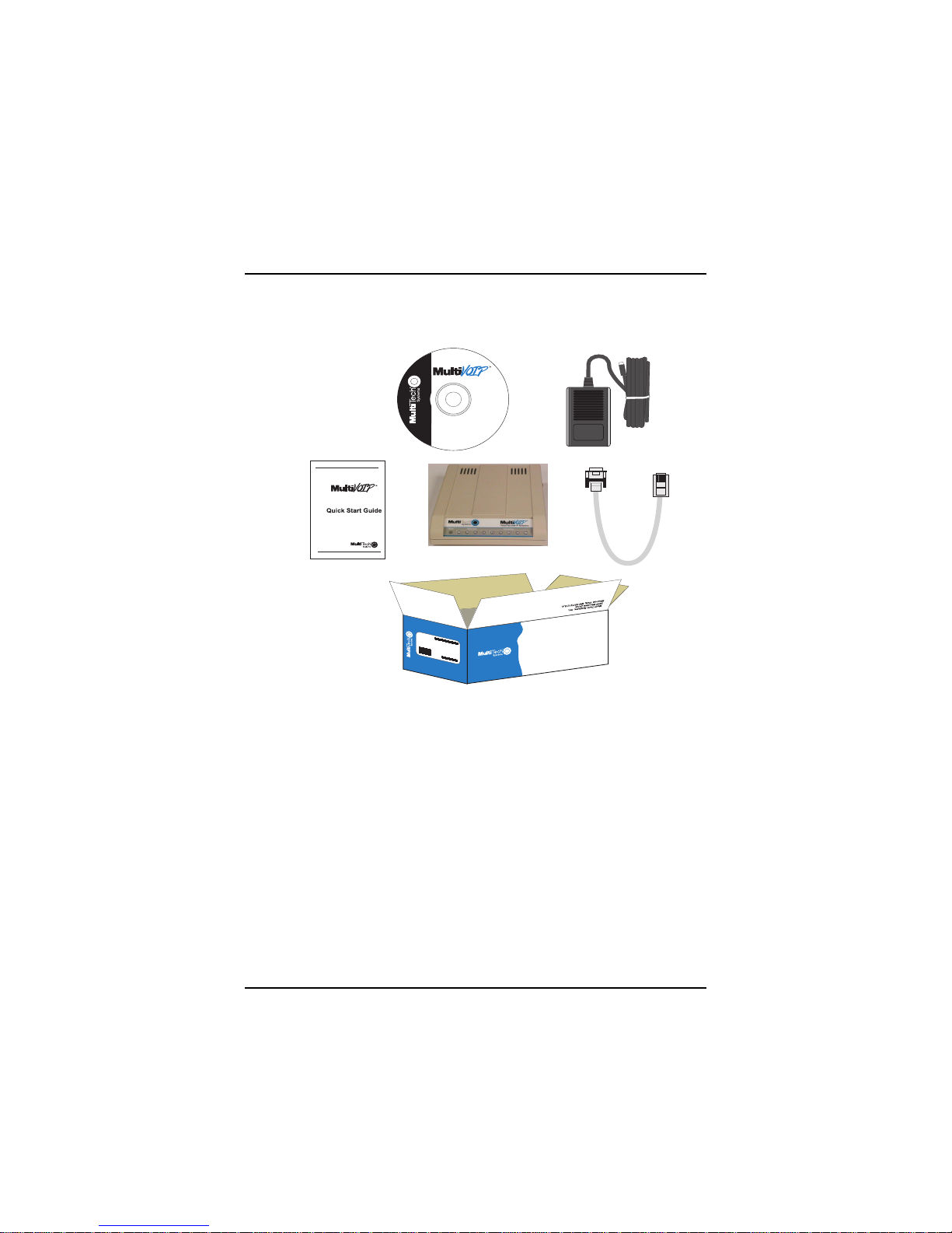
Unpacking Your MultiVOIP
Remove all items from the box. (See Figure 2.)
Voice/Fax over IP Networks
www.multitech.com
MADE IN U.S.A
Figure 2. Unpacking
.A
.S
U
IN
E
D
A
M
Safety Warnings
Caution: Danger of explosion if battery is incorrectly replaced.
A lithium battery on the circuit board provides backup power
for the time keeping capability . The battery has an estimated
life expectancy of ten years.
When the battery starts to weaken, the date and time may be
incorrect. If the battery fails, the board must be sent back to
Multi-Tech Systems for battery replacement.
The Ethernet port is not designed to be connected to a Public
Telecommunication Network. FXO can be connected to a
public or PSTN network.
8
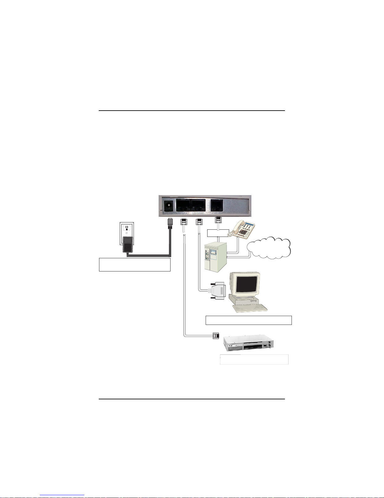
Cabling Your MultiVOIP
Cabling your MultiVOIP involves properly connecting the
Power, Command Port, phone/PBX, and Ethernet. Figure 3
shows the back panel connectors and the associated cable
connections.
Cabling Procedure
1. Using the supplied cable, connect the power supply to a
live AC outlet, then plug the power supply into the
MVP120.
FXO
Power Connection
Cabling
PSTN
Command Port Connection
Hub
Network Connection
Figure 3. Cable Connections
9

MultiVOIP Quick Start Guide
2. Connect the MVP120 to a PC using the RJ-45 to DB9
(female) cable provided with your unit. Plug the RJ-45 end
of the cable into the Command port of the MVP120 and
connect the other end to the PC’s serial port (Figure 3).
3. Connect a network cable to the Ethernet 10Base-T
connector on the back of the MVP120. Connect the other
end of the cable to your network.
4. Connect an RJ-11 cable to the Voice/Fax Channel
connector on the back of the MVP120 and the other end to
the PSTN or FXO PBX port.
5. Turn on power to the MVP120 by setting the power switch
on the right side to the On position. Wait for the Boot LED
on the MVP120 to go off before proceeding. This may take
a couple of minutes.
Note: Since the MVP120 doesn’t have a power LED, no
LEDs will be lit if there is no activity after boot up, unless
the ethernet port is connected to the network.
10
Installing the Software
Installing Your MVP120 Software
These following installation procedures do not cover every
screen or option; it is assumed that a technical person with a
thorough knowledge of Windows and the software loading
process is doing the installation. Additional information on the
MVP120 software is provided in the online Help.
Note: The phonebook directory configuration process is
different depending on whether or not you have an enabled
H.323 Gatekeeper resident in your network. The “Configuring
Your MultiVOIP” section explains these differences.
The MVP120 software and User Guide are contained on the
MVP120 Installation CD. When you have finished configuring
your MVP120, you can view and print the User Guide by
clicking the Install Manuals icon.
CAUTION: If you are installing the MVP120 behind a firewall,
the Firewall must support H.323. Refer to your Firewall user
documentation to enable H.323 support.
1. Make certain that your MVP120 has been properly cabled
and that its power is turned on.
2. Insert the MVP120 Installation CD into a CD-ROM drive.
The CD is auto-detectable, so it starts automatically . It
may take 10 to 20 seconds for the Multi-Tech Installation
CD window to appear.
11
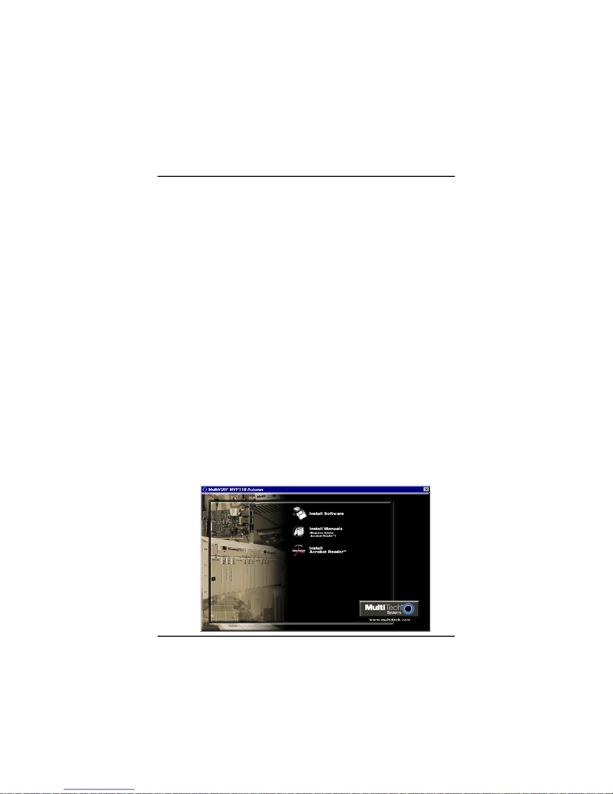
MultiVOIP Quick Start Guide
If the Multi-Tech Installation CD window does not appear
automatically , click My Computer, then right-click the CD-
ROM drive icon, click Open, then click the Autorun icon.
3. When the Multi-Tech Installation CD window displays, click
the Install Software icon.
4. You will then be prompted to select your software:
H.323 or Proprietary.
Select H.323.
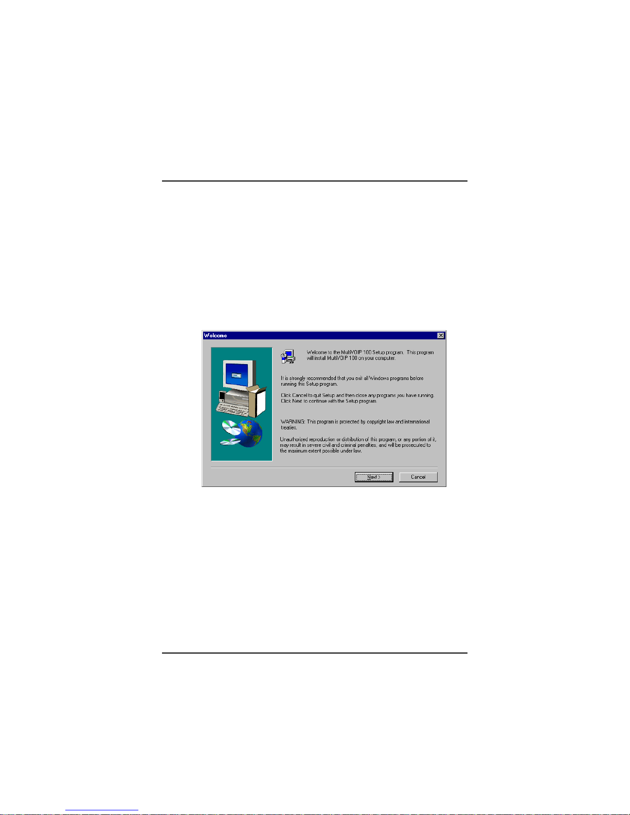
5. The Welcome/Setup dialog box displays.
Press Enter or click Next to continue.
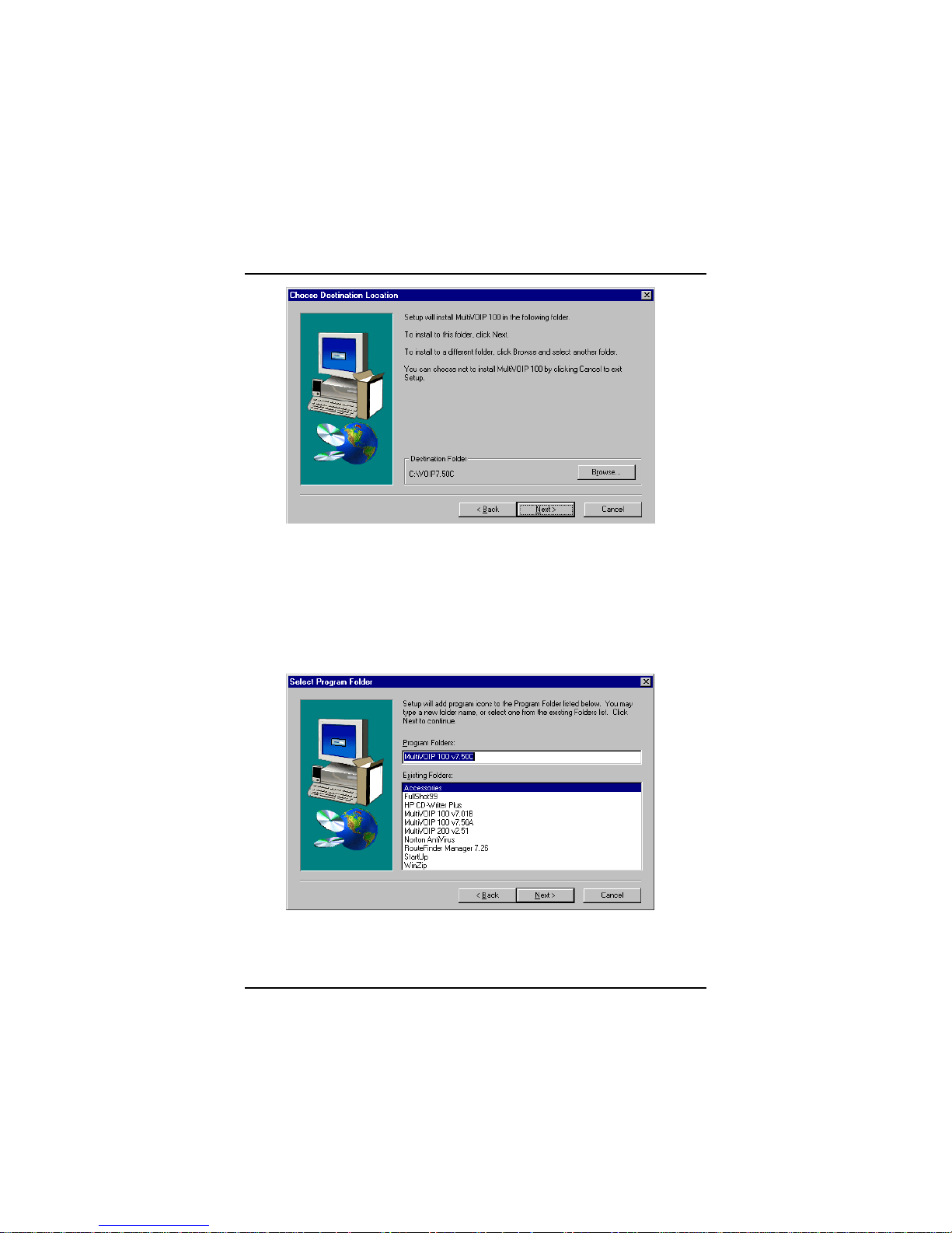
6. The Choose Destination Location dialog box displays.
Follow the on-screen instructions.
12
Installing the Software
You can either choose the Destination Location of
your MVP120 software or select the default
destination by clicking Next. If you click Browse,
you can select a different destination folder for the
MVP120 software.
7. In the Select Program Folder dialog box, select
where you want the program file to be located.
Verify the path and click Next to continue.
13

MultiVOIP Quick Start Guide
8. The Copying program files window displays, followed
by the MVP120 Setup dialog box. This dialog box enables
you to select the COM port of your PC that is connected to
the Command port of the MVP120. From the Select Port
list, select the COM port of your PC.
Click OK to continue.
9. The Setup Complete dialog displays.
14
Configuring the MultiVOIP
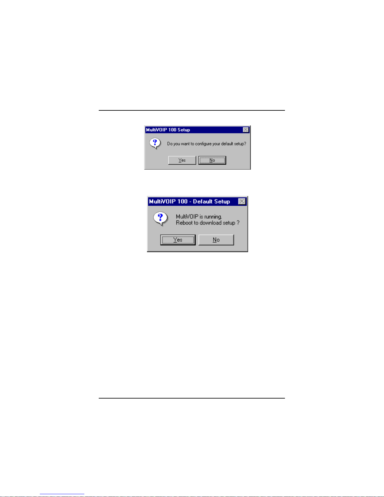
10. The following message displays:
Click Yes to continue.
1 1. The following message displays.
Click Yes to continue.
The IP Protocol Default Setup dialog box displays next
(see page 16) as you continue configuring your MultiVOIP.
15
 Loading...