

Multitech MultiModem MT9234ZPX-PCIE, MultiModem MT9234ZPX-PCIE-NV, MultiModem MT9234ZPX-UPCI, MultiModem MT9234ZPX-UPCI-NV Quick Start Manual
Page 1

MultiModem® ZPX
V.92 Internal Modem
MT9234ZPX-UPCI
MT9234ZPX-UPCI-NV
MT9234ZPX-PCIE
MT9234ZPX-PCIE-NV
Quick Start Guide
Page 2

2 Multi-Tech Systems, Inc.
MultiModem ZPX Quick Start Guide
V.92 Internal Modem
MT9234ZPX-UPCI, MT9234ZPX-UPCI-NV
MT9234ZPX-PCIE, MT9234ZPX-PCIE-NV
82100130L Rev. A
Copyright
This publication may not be reproduced, in whole or in part, without prior expressed
written permission from Multi-Tech Systems, Inc. All rights reserved.
Copyright © 2007 Multi-Tech Systems, Inc.
Multi-Tech Systems, Inc. makes no representations or warranty with respect to the
contents hereof and specifically disclaims any implied warranty of merchantability or
fitness for any particular purpose. Furthermore, Multi-Tech Systems, Inc. reserves
the right to revise this publication and to make changes from time to time in the
content hereof without obligation of Multi-Tech Systems, Inc. to notify any person or
organization of such revisions or changes. Check Multi-Tech’s Web site for current
versions of our product documentation.
Revision Date Description
A 12/28/07 Initial release.
Trademarks
Multi-Tech, MultiModem, and the Multi-Tech logo are registered trademarks of
Multi-Tech Systems, Inc. Windows 2000, 2003, XP, and Vista are registered
trademarks of Microsoft in the U.S. and other countires. All other brand and
product names mentioned in this publication are trademarks or registered
trademarks of their respective companies.
Patents
This Product is covered by one or more of the following U.S. Patent Numbers:
6151333, 5757801, 5682386, 5.301.274; 5.309.562; 5.355.365; 5.355.653;
5.452.289; 5.453.986;7082106;7082141;7092406. Other Patents Pending.
Technical Support
Country By Email By Phone
Europe, Middle East, Africa: support@multitech.co.uk
+(44) 118 959 7774
U.S., Canada. all others: support@multitech.com
(800) 972-2439 or
+763-717-5863
World Headquarters
Multi-Tech Systems, Inc.
2205 Woodale Drive
Mounds View, Minnesota 55112 U.S.A.
(763) 785-3500 or (800) 328-9717
Fax (763) 785-9874
http://www.multitech.com
Page 3
MultiModem Quick Start Guide
Multi-Tech Systems, Inc. 3
Introduction
This guide shows you how to set up your MultiModem ZPX. For detailed
information, product specifications, troubleshooting tips, and more, see the User
Guide, available on your MultiModem CD.
Check Multi-Tech’s Web site for current versions of our product documentation.
Safety Warnings
• Use this product only with UL- and CUL-listed computers.
• To reduce the risk of fire, use only UL-listed 26 AWG (.41mm) or larger
telephone wiring.
• Never install telephone wiring during a lightning storm.
• Never install a telephone jack in a wet location unless the jack is specifically
designed for wet locations.
• Never touch uninsulated telephone wires or terminals unless the telephone
line has been disconnected at the network interface.
• Use caution when installing or modifying telephone lines.
• Avoid using a telephone during an electrical storm; there is a risk of electrical
shock from lightning.
• Do not use a telephone in the vicinity of a gas leak.
• The telephone cord is to be disconnected before accessing the inside of the
equipment.
Package Contents
• One MultiModem ZPX
• One RJ11 telephone cable
• One printed Quick Start Guide
• One product CD
• One low profile mounting bracket (MT9234ZPX-PCIE models only)
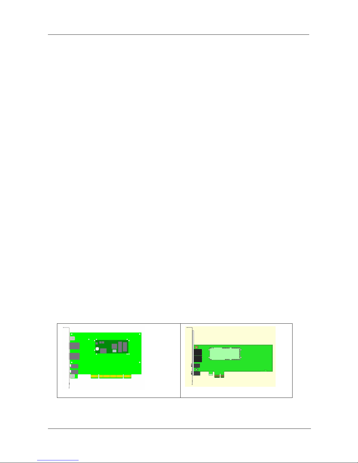
Installing your MultiModem
Installing the MultiModem requires you to open your system. Please consult your
system manual in addition to the following instructions.
MT9234ZPX-UPCI
MT9234ZPX-PCIE
1. Turn off your system and unplug it. Failure to do so may result in damage to
both the MultiModem and your system. Do not turn on the system until the
instructions tell you to do so.
Page 4
MultiModem Quick Start Guide
4 Multi-Tech Systems, Inc.
2. Remove the cover from your system as instructed in the system manual.
3. If you are installing a MT9234ZPX-PCIE board in a low profile machine, you
will have to change the mounting bracket to the low profile mounting bracket.
Refer to your User Guide for low profile mounting bracket details.
4. Select an empty PCI expansion slot. Remove the expansion slot cover and
save the retaining screw.
5. Before handling the MultiModem, discharge static in your body by touching a
bare piece of metal on the chassis. Carefully remove the MultiModem from its
antistatic bag, handling it only by the mounting bracket and edges. Do not
touch the gold-plated connectors along the bottom edge.
6. Look at the system’s main board to determine either PCI or Express
connector. Place the MultiModem directly above the expansion slot and
gently, but firmly, push it into the connector until the card’s retaining bracket
is flush against the system chassis.
7. Fasten the retaining bracket to the system chassis with the screw saved in
step 4.
8. Replace the system cover.
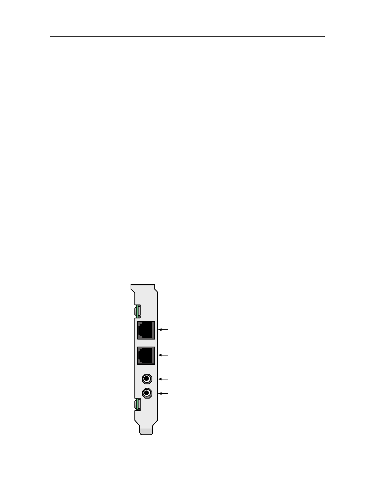
Making External Connections
Now, connect the MultiModem to the telephone line and, optionally, to your
telephone. For voice mail or speakerphone, you can also connect it to a
microphone and an external speaker, headphone, or sound card. The microphone
can be used for recording answering machine messages or for speakerphone use.
The speaker or headphone can be used for playing back messages or as a
speakerphone.
LINE
MI C
LINE
PH ONE
Optional Voice
MI C IN
LINE OUT
PHONE
LINE
Page 5

MultiModem Quick Start Guide
Multi-Tech Systems, Inc. 5
Line Connection
Plug one end of the provided telephone cable into the modem’s LINE jack, and
the other end into a telephone wall jack. This is the only required connection.
Important: The LINE jack is not interchangeable with the PHONE jack. Do not
plug the phone into the LINE jack or the line cable into the PHONE jack.
Note: The Federal Communications Commission (FCC) and Industry
Canada impose certain restrictions on equipment connected to public
telephone systems.
Phone Connection (Optional)
If you wish to connect a telephone to the same line as the modem, plug
it into the modem PHONE jack. Important: The PHONE jack is not interchangeable
with the LINE jack. Do not plug the phone into the LINE jack or the line cable into
the PHONE jack.
Microphone/Headphone Connection (Optional)
For voice mail or speakerphone applications, plug an unamplified microphone into
the MIC jack. The microphone and headphone should have a stereo 3.58mm (9/64inch) mini plug. Do not use a monophonic microphone.
Installing the Modem Dr iver
The MT9234ZPX drivers need to be installed in your computer’s program directory.
The procedure will be different depending on the operating system. The first section
provides installation for the Vista Operating System. The second section provides
installation for Windows 2000 thru Windows XP Operating Systems. If you use a
Linux operating system, please refer to Appendix D in the User Guide for
installation instructions.
Vista Operating System
The MT9234ZPX driver installation is done in three parts, each directed by an
installation wizard. The three parts are: (1) installation of your PCI Serial Port, (2)
installation of the Communications Port, and (3) installation of the modem.
Preliminaries
1. Power up your computer.
2. Windows will detect that the new modem is present.
Driver Installation of your PCI Serial Port
3. The Found New Hardware screen appears with Windows needs to
install driver software for your PCI Serial Port.
Page 6

MultiModem Quick Start Guide
6 Multi-Tech Systems, Inc.
Click on Locate and install driver software (recommended). Windows
will guide you through the process of installing driver software for your
device.
4. The next screen prompts you to insert the disc that came with your PCI
Serial Port. If you have the disc that came with your device, insert it now.
Windows will automatically search the disc for driver software.
Click Next.
5. Windows couldn’t find driver software for your device screen
appears. Choose Browse my computer for driver software
(advanced).
Page 7

MultiModem Quick Start Guide
Multi-Tech Systems, Inc. 7
6. At the Browse for driver software on your computer screen, click the
Browse button.
7. Select the Drivers folder, and then the Vista folder on the product CD.
Click Next.
8. Searching D:\Drivers\Vista for software… screen appears.
9. When the software for this device has been successfully installed screen
appears with Windows has finished installing the driver software for this
device: Multi-Tech’s 1-Port PCI Analog Modem Card.
Click Close.
Page 8

MultiModem Quick Start Guide
8 Multi-Tech Systems, Inc.
Installation of the Communications Port
10. The Found New Hardware – Multifunction Device screen appears with
Insert the disc that came with your Multifunction Device.
The MT9234ZPX-PCI product CD is still in the CDROM drive. Click Next.
11. At the Windows couldn’t find driver software for your device, click on
Browse my computer for driver software (advanced). Locate and
install driver software manually.
12. At the Browse for driver software on your computer screen, click the
Browse button and select the Drivers folder, then the Vista folder on the
product CD.
13. Click Next.
14. Installing driver software… activity screen appears.
15. Windows can’t verify the publisher of this driver software screen
appears.
Page 9

MultiModem Quick Start Guide
Multi-Tech Systems, Inc. 9
Select Install this driver software anyway.
16. Installing driver software progress screen appears.
17. The software for this device has ben successfully installed screen
appears with Windows has finished installing the driver software for this
device: Multi-Tech Communications Port.
Click Close.
Installation of the Modem
18. The Found New Hardware – MultiTech Systems MT9234ZPX-PCIE
screen appears with Insert the disc that came with your MultiTech
Systems MT9234ZPX-PCIE.
The MT9234ZPX-PCI product CD is still in the CDROM drive. Click Next.
Page 10

MultiModem Quick Start Guide
10 Multi-Tech Systems, Inc.
19. At the Windows couldn’t find driver software for your device, click on
Browse my computer for driver software (advanced). Locate and
install driver software manually.
20. At the Browse for driver software on your computer screen, click the
Browse button and select the Drivers folder, then the Vista folder on the
product CD.
21. Click Next.
22. Windows can’t verify the publisher of this driver software screen
appears.
Select Install this driver software anyway.
23. Installing driver software progress screen appears.
24. The software for this device has ben successfully installed screen
appears with Windows has finished installing the driver software for this
device: Multi-Tech Systems MT9234ZPX-PCIE.
25. Click Close. The installation of drivers is now complete.
Page 11

MultiModem Quick Start Guide
Multi-Tech Systems, Inc. 11
Windows 2000 and XP Operating Systems
The MT9234ZPX driver installation is done in three parts, each directed by an
installation wizard. The three parts are: (1) installation of the Single-port UART PCI
Card, (2) installation of the Communications Port, and (3) installation of the modem.
Preliminaries
1. Power up your computer.
2. Windows will detect that the new modem is present.
Installation of the Single-Port UART PCI Card
The wizard will install the files for the 1-port UART PCI Card.
3. The Found New Hardware Wizard screen appears. In response to the
question, “Can Windows connect to Windows Update to search for
software?” select “No, not this time” and click Next.
4. The next screen prompts you to insert the product CD into the computer.
Insert the product CD, and select Install from a list or specific location
(Advanced).
Click Next.
5. At the Please Choose Your Search and Installation Options screen,
select Search for the best driver in these locations and browse on the
product CD to the Drivers folder and then the Windows_XP_2K folder.
Select the relevent processor/operating system, AMD64, IA64, or X86.
Click OK and click Next.
6. A has not passed Windows logo testing screen appears. Click
Continue An yway.
Page 12

MultiModem Quick Start Guide
12 Multi-Tech Systems, Inc.
Note: This Microsoft operating system searches for a digital signature when
you install any new hardware. If a “has not passed Windows logo
testing” screen (or Digital Signature Not Found screen) appears, simply
click Continue Anyway (or YES) to continue installation. Although MultiTech submits all eligible products to Microsoft for certification, the turnaround time is subject to many factors. Not having a digital signature
does not affect product performance in any way.
7. A Completing the Found New Hardware Wizard screen will appear.
This wizard has finished installing the software for: Multi-Tech’s 1-port
UART PCI Card. Click Finish.
Installation of the Communications Port
The wizard will install the files for the Multi-Tech Communications Port.
8. The Welcome to the Found New Hardware Wizard screen appears.
This wizard helps you install software for: Multifunction Device. Select
Install from a list or specific location (Advanced).
Click Next.
9. At the Please Choose Your Search and Installation Options screen,
select Search for the best driver in these locations and browse on the
product CD to the Drivers folder. Select the relevent processor, AMD64,
IA64, or X86. Click OK and click Next.
10. A has not passed Windows logo testing screen appears. Click
Continue An yway. (See note on logo testing above.)
11. A Completing the Found New Hardware Wizard screen will appear.
This wizard has finished installing the software for: Multi-Tech
Communications Port. Click Finish.
Page 13

MultiModem Quick Start Guide
Multi-Tech Systems, Inc. 13
Installation of the Modem
The wizard will install the file for Multi-Tech Systems MT9234ZPX Models.
12. The Welcome to the Found New Hardware Wizard screen appears for
a third time. This wizard helps you install the software for: Multi-Tech
Systems MT9234ZPX-UPCI. Select Install from a list or specific
location (Advanced).
Click Next.
13. At the Please Choose Your Search and Installation Options screen,
select Search for the best driver in these locations and browse on the
product CD to the Drivers folder I multitech_pcie_upci-zpx.
14. A Completing the Found New Hardware Wizard screen will appear.
The wizard has finished installing the software for: Multi-Tech Systems
MT9234ZPX-UPCI. Click Finish.
The installation of drivers is now complete.
Configure the Modem for Your Country
Different countries have different requirements for how modems must function.
Therefore, before you use your modem, you must configure it to match the defaults
of the country in which you are using it. The modem is set to country, Euro/NAM,
with a country code of 52 decimal by default. You can use one of two configuration
methods:
• Using the Global Wizard to Configure Your Modem
• Using AT Commands to Configure Your Modem
Page 14

MultiModem Quick Start Guide
14 Multi-Tech Systems, Inc.
Using Global Wizard to Configure Your Mod em
The Global Wizard configuration utility is recommended for computers running
Windows 2000 or newer.
1. Insert the MultiModem system CD into the CD-ROM drive.
2. When the splash screen appears, click Initial Setup & Country Sel button.
3. Choose either:
• Run Global Wizard from CD. This will not load the wizard onto your hard
drive, or
• Install Global Wizard on the HD. This will install the wizard onto your
hard drive for future use.
4. The Global Wizard dialog box appears. Click Next.
5. The Wizard searches for your modem and identifies it. Click Next.
6. Select the country in which the modem will be used. Click Next.
7. Review your choice of country. If it is correct, click Next to configure the
modem.
8. When Global Wizard announces that the parameters have been set, click
Finish to exit.
Using AT Commands to Configure Your Modem
Non-Windows users can configure the modem using AT commands. You must
enter these commands in your communication program terminal window.
1. Run your favorite communication program and open the program terminal
window.
2. To configure the modem for a specific country:
Type AT%T19,0,nn (where nn is the country code in hexadecimal format
Press ENTER.
The message OK displays.
3. To verify the change:
Type ATI9.
Press ENTER.
The country code is displayed in decimal format, as in this example:
Country
AT command
(hexadecimal)
Country code
(decimal)
Euro/NAM AT%T19,0,34 (default) 52
The complete list of country codes can be found on the Multi-Tech
Web site at http://www.multitech.com/GlobalModem/config.
Page 15

MultiModem Quick Start Guide
Multi-Tech Systems, Inc. 15
Page 16

82100130L
 Loading...