

Page 1

MultiModemISI Hybrid Series
Model ISIHI-2S
88301150
Copyright © 1998 by Multi-Tech Systems, Inc.
Page 2

MultiModemISI Hybrid Series
Model ISIHI-2S
88301 150, Revision A
All rights reserved. This publication may not be reproduced, in whole or in part, without prior expressed
written permission from Multi-Tech Systems, Inc.
Copyright © 1998 by Multi-Tech Systems, Inc.
Multi-Tech Systems, Inc. makes no representation or warranties with respect to the contents hereof and
specifically disclaims any implied warranties of merchantability or fitness for any particular purpose.
Furthermore, Multi-Tech Systems, Inc. reserves the right to revise this publication and to make changes
from time to time in the content hereof without obligation of Multi-Tech Systems, Inc., to notify any
person or organization of such revisions or changes.
Record of Revisions
Revision Date Description
A 8/1 1/98 Manual released.
Patents
This product is covered by one or more of the following U.S. Patent numbers: 5.301.274, 5.309.562,
5.355.365, 5.355.653, 5.452.289, 5.453.986. Other patents pending.
Trademarks
Multi-Tech is a registered trademark of Multi-Tech Systems, Inc.
NetWare is a registered trademark of Novell, Inc.
Pentium is a registered trademark of Intel Corporation.
SCO is a registered trademark of Santa Cruz Operation, Inc.
UNIX is a reigstered trademark of X/Open Company, Ltd.
Windows 95 and Windows NT are registered trademarks of Microsoft.
Multi-Tech Systems, Inc.
2205 Woodale Drive
Mounds View , Minnesota 55112
(612) 785-3500 or (800) 328-9717
U.S. Fax (612) 785-9874
Technical Support (800) 972-2439
BBS (612) 785-3702 or (800) 392-2432
Fax Back (612) 717-5888
Internet Address:http://www.multitech.com
Page 3

Contents
Chapter 1—Introduction
Welcome to Multi-Tech’s ISIHI-2S....................................................................................................................6
Modem Description/Features........................................................................................................................... 7
T erminal Adapter Description/Features............................................................................................................ 8
Manual Organization...................................................................................................................................... 10
T echnical Specifications................................................................................................................................. 12
Physical / Electrical / Environmental.......................................................................................................... 12
Modem...................................................................................................................................................... 12
T erminal Adapter.......................................................................................................................................14
Chapter 2—Hardware Installation
Introduction.................................................................................................................................................... 16
Computer Requirements.......................................................................................................... ................. 16
Shipping Contents.....................................................................................................................................16
Safety Warnings........................................................................................................................................ 16
Before Y ou Start ............................................................................................................................................ 17
Determine Current System Settings..........................................................................................................18
Installing the ISIHI-2S .................................................................................................................................... 19
Chapter 3—Software/Driver Installation
Introduction.................................................................................................................................................... 22
Installing ISIHI-2S Drivers in Windows NT ..................................................................................................... 23
Installing Terminal Adapters and Modems to COM Ports in Windows NT ................................................. 25
Removing the Driver ................................................................................................................................. 30
Installing ISIHI-2S Drivers in Windows 95...................................................................................................... 31
Installing Terminal Adapters and Modems to COM Ports in Windows 95 .................................................. 39
Removing the Driver ................................................................................................................................. 43
Configuring the Terminal Adapter................................................................................................................... 44
Before Y ou Start........................................................................................................................................44
To Configure the T erminal Adapter ............................................................................................................ 46
ISDN TA Configuration Utility ..............................................................................................................46
ConfigMenu Configuration Utility ........................................................................................................50
A T Commands....................................................................................................................................51
NetWare Connect (Novell) Driver Installation................................................................................................. 52
Configuring Ports for NetWare Connect.................................................................................................... 53
Removing the Driver (Novell) ....................................................................................................................53
SCO Open Server 5 Driver Installation .......................................................................................................... 54
The Multi-Tech Installation Script .............................................................................................................. 55
Activating Ports in SCO Open Server 5 .................................................................................................... 57
Removing the Driver (SCO Open Server 5) .............................................................................................. 57
Multi_Setup Utility .....................................................................................................................................58
Administration Utility ................................................................................................................................. 61
Chapter 4—MODEM AT Commands, S-Registers, and Result Codes
Modem A T Commands .................................................................................................................................. 64
Modem S-Registers .......................................................................................................................................83
Modem Result Codes ....................................................................................................................................89
Chapter 5—TERMINAL ADAPTER AT Commands, S-Registers, and Result Codes
T erminal Adapter A T Commands.................................................................................................................... 92
T erminal Adapter S-Registers ......................................................................................................................105
Terminal Adapter Result Codes ................................................................................................................... 108
Chapter 6—Troubleshooting
.................................................................................................................................................................... 112
Page 4

Chapter 7—Service, Warranty, and Technical/BBS
Introduction.................................................................................................................................................. 11 8
Limited Warranty.......................................................................................................................................... 118
Service ........................................................................................................................................................ 119
The Multi-Tech BBS ..................................................................................................................................... 1 19
Upgrading the ISIHI-2S with FlashPro ......................................................................................................... 121
About CompuServe ..................................................................................................................................... 121
About the Internet ........................................................................................................................................ 121
Appendix
Appendix A: Determining Current System Settings...................................................................................... 124
Appendix B: Base I/O Switch Settings ......................................................................................................... 125
Appendix C: Pin Assignments...................................................................................................................... 129
Appendix D: ISIHI-2S Testing Utilities .......................................................................................................... 130
Appendix E: Configuration Profiles ............................................................................................................. 133
Appendix F: Ordering ISDN BRI (2B+D) Lines ............................................................................................138
Appendix G: ASCII Conversion Chart.......................................................................................................... 149
Appendix H: Dial Pulses and Tones ............................................................................................................. 150
Appendix I: AT Command Summary (Modem)............................................................................................. 152
Appendix J: S-Register Summary (Modem)................................................................................................. 157
Appendix K: Result Code Summary (Modem) .............................................................................................158
Appendix L: AT Command Summary (T A) ................................................................................................... 160
Appendix M: S-Register Summary (TA)....................................................................................................... 165
Appendix N: Result Codes (TA) ................................................................................................................... 166
Appendix O: Regulatory Agency Information ............................................................................................... 167
Glossary
.................................................................................................................................................................... 170
Index
.................................................................................................................................................................... 182
Page 5

MultiModemISI Hybrid Series, ISIHI-2S 5
Introduction1
Page 6
Chapter 1– Introduction
elcome to Multi-Tech’s
new MultiModemISI Hybrid Series, model ISIHI-2S, a multiport hybrid ISDN card for
Remote Access Server (RAS) applications. Included on the ISIHI-2S are four V.90/
W
K56flex central site modems for incoming analog modem and fax calls, as well as two
terminal adapters. Each terminal adapter appears as two ports to the server PC using the
ISIHI-2S. The terminal adapters identify incoming analog calls and route them to the
central site modems. The card also supports dial-out applications via the modems or
terminal adapters.
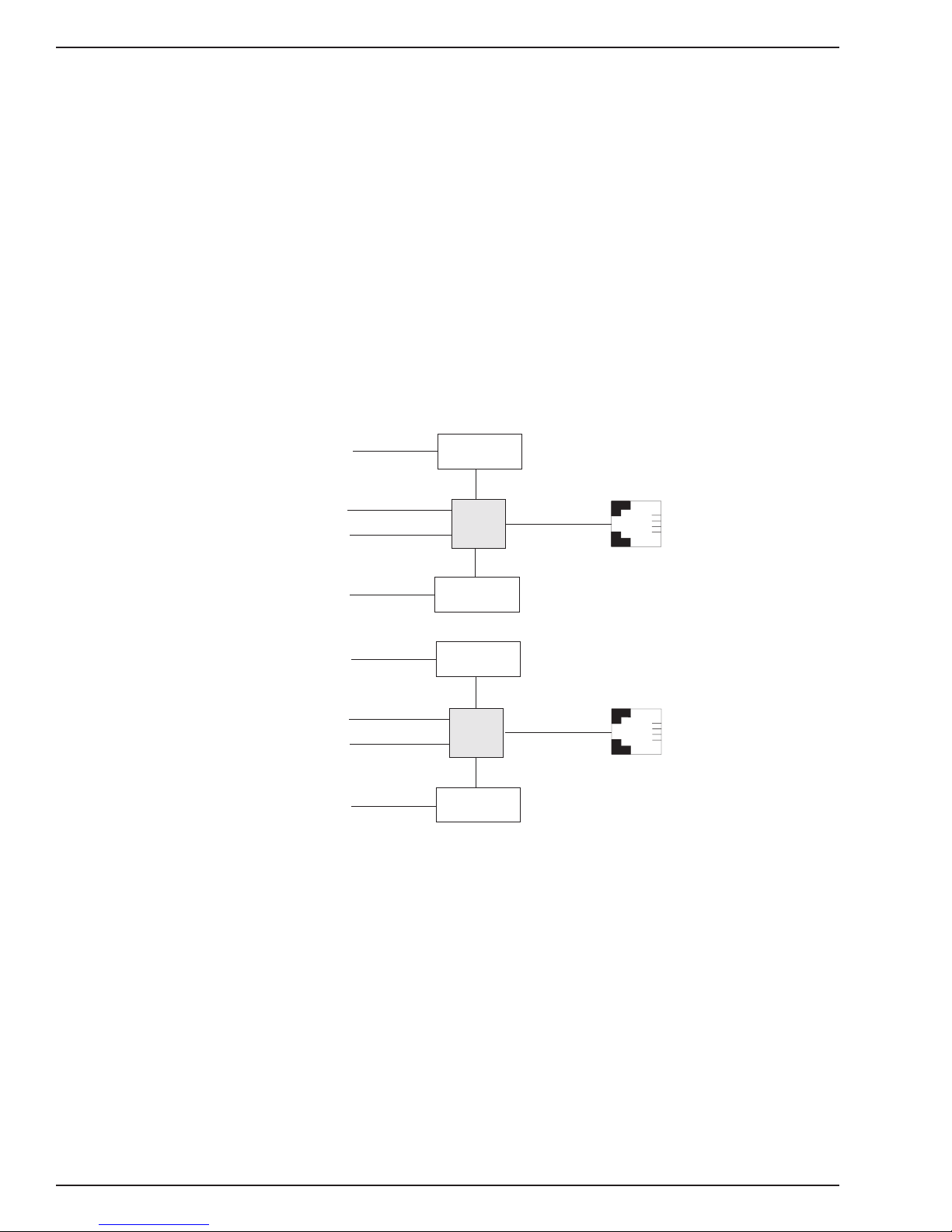
The ISIHI-2S card features eight RAS ports using two Basic Rate Interface (BRI) ISDN
lines. The eight ports allow a server to accept any combination of analog modem and
digital ISDN calls, giving the user the flexibility to customize the settings of the terminal
adapters and modems. Since the two BRI lines constitute only four Bearer channels, only
four of the eight ports can be active at any one time. The two terminal adapters handle
the four B-channels as four independent data connections (see diagram below).
Com Ports
5
1
2
6
7
3
4
8
Modem
TA
Modem
Modem
TA
Modem
ISDN
RJ-45 jack
3456
RJ-45 jack
3456
Line 1
Line 2
6 MultiModemISI Hybrid Series, ISIHI-2S
Page 7

Chapter 1– Introduction
From the perspective of the server PC, the ISIHI-2S is an 8-port serial card with eight
devices permanently attached to the serial ports. The first four ports are the two terminal
adapters, each of which appear as two ports. The remaining four ports are the four
central site modems. The chart below summarizes the correlation of ports and devices.
Port Number Device ISDN Line Number
1TA 1
2TA 1
3TA 2
4TA 2
5 Modem 1
6 Modem 1
7 Modem 2
8 Modem 2
The ISIHI-2S server card is ideal for use in PC network environments because it provides
an integrated hardware solution for remote access for both Windows NT and Novellbased LANs. To ensure smooth Novell network integ/ration, the ISIHI-2S ships with a
NetWare Loadable Module for NetW are Connect™ communication server that enables it
to support state-of-the-art features such as remote dialing and modem pooling. The
ISIHI-2S easily integrates into the Windows NT platform since it fully supports Microsoft’s
Remote Access Server software, which allows it to operate comfortably with popular
network protocols such as TCP/IP and Net BIOS. The ISIHI-2S ships with drivers for
other multiuser operating systems such as SCO®UNIX®.
This Owner’s Manual will help you install, configure, test, and use the ISIHI2-S. The
manual contains product specifications, installation instructions, and technical support
information to assist you in the installation process. This manual is written for audiences
with basic PC skills; therefore, step-by-step instructions for basic operations such as
logging in and file editing are not included.
Modem Description/Features
ISIHI-2S modems include an Intel 20 MHz 80186 processor and 254K of RAM that work
dynamically to allocate resources to the most active modems.
Simple to install, the ISIHI-2S can be used to add multiport, Enhanced V.34 modem
communications to a network host or server as easily as plugging in an expansion card,
loading the driver software, and connecting the phone lines.
The ISIHI-2S contains four modems, which meet the proposed Enhanced V.34 ITU
standard for data signalling rates as high as 33.6/31.2 Kbps full-duplex mode. They
support and are compatible with EIA extended Automode, adaptive line probing,
automatic symbol rate and carrier frequency during startup, and retrain and rate
renegotiation (in 2400 bps increments.)
The ISIHI-2S features CCITT V.42 error correction and V.42bis data compression,
providing 100% error-free data transmission. V.42 error correction incorporates MNP
Classes 3 and 4 and LAP-M. You can select V.42bis data compression for 4-1 throughput
or MNP Class 5 for 2-1 throughput.
MultiModem ISI Hybrid Series, ISIHI-2S 7
Page 8

Chapter 1– Introduction
ISIHI-2S modems offer interactive automatic dialing as well as Command Mode option
configuration. You can store up to ten command line/telephone numbers (up to 60
characters each) in the ISIHI-2S’s nonvolatile memory.
ISIHI-2S modems offer pulse or tone dialing and recognize dial tones and busy signals
for reliable call-progress detection. They detect A T&T calling card tones and are FCCregistered for connecting to telephone networks without Data Access Arrangements
(DAAs).
They also feature Remote Configuration, which allows you to assist users at remote
sites, saving you the time and trouble of site visits and preventing misinterpretation of
configuration instructions.
The ISIHI-2S meets the CCITT V.17 standard for sending and receiving faxes. When
lined to a compatible fax machine or modem, ISIHI-2S modems can transmit faxes at
14.4 Kbps. They meet the CCITT’s Group 3 Designation for sending and receiving faxes
at 9600 bps and Group 2 Designation for sending and receiving faxes at 1800 bps. The
ISIHI-2S also is downward-compatible to speeds as low as 300 bps, so you can send
and receive faxes with virtually any fax machine in the world.
Terminal Adapter Description/Features
ISIHI-2S terminal adapters have S/T ports to connect to the ISDN network and analog
ports to connect to a telephone, modem, or fax machine. They ship with a software
configuration utility for Windows® 95, Windows NT, and ConfigMenu (a built-in
configuration utility for DOS and Windows 3.x operating systems). The TAs also accept
A T commands, enabling them to use the same communications software as analog
modems.
ISIHI-2S terminal adapters are compatible with EuroISDN switch protocol. They
communicate using ISDN BRI (2B+D) service, which provides up to 128 Kbps data and
voice communications. They automatically detect whether an incoming call is voice or
data and handle it appropriately.
The ISIHI-2S terminal adapters communicate over public ISDN telephone lines. Features
include the following:
• Compatibility with NET3, AT&T 5ESS, NT DMS-100, US National ISDN-1switch
protocols
• Automatically detect if incoming call is voice or data
• ISDN BRI (2B+D)
• AT command and S-Register controls and Result Code responses
• Use the same communications software as existing analog modems
• V.120, PPP, or X.75 compatible
• Supports PPP (Point-to-Point Protocol) high speed ISDN connections
• Windows NT and Windows 95 software utility and a firmware utility for easy ISDN line
configuration
8 MultiModemISI Hybrid Series, ISIHI-2S
Page 9

Chapter 1– Introduction
• Flash PROM for easy firmware upgrades
• Automatic detection of the data protocol for answering incoming data calls
• Embedded protocol analyzer for troubleshooting the connection to the ISDN network
The ISDN TAs provide data communication using Basic Rate Interface (BRI). They
provide two 64 Kbps
bearer
channels for voice or data and one 16 Kbps D channel for
signaling information (2B+D) and are compatible with V.120, PPP , and X.75.
The TAs provides dial-up asynchronous communication capability with other personal
computers, terminals, on-line computer services, or other types of computer systems.
What is a S/T-Interface? An ISDN Basic Rate (BRI) U-Loop consists of 2 conductors
from the CO (telephone company central office) to the customer premises. Equipment on
both sides of the U-loop is carefully designed to deal with the long length of the U-loop
and the noisy environment it operates in. At the customer premises, the U-loop is
terminated by an NT1 (network termination 1) device. An NT1 (network terminator 1) is a
device that provides an interface between the two-wire twisted-pairs used by telephone
companies in their ISDN BRI network and an end-user’s four wire terminal equipment.
The NT1 drives an S/T-bus that usually is 4 wires but in some cases may be 6 or 8 wires.
The name of the S/T bus comes from the letters used in the ISDN specifications to refer
to two reference points, S and T. Point T refers to the connection between the NT1
device and customer supplied equipment. Terminals can connect directly to NT1 at point
T, or there may be a PBX (private branch exchange, e.g., a customer-owned telephone
exchange). When a PBX is present, point S refers to the connection between the PBX
and the terminal.
Note that in ISDN terminology,
terminal
can mean any sort of end-user ISDN device,
such as data terminals, telephones, FAX machines, etc. The following diagram reflects
interface points in a typical ISDN network.
Terminal
Terminal
Point S
48 wires
NT2
(PBX)
Point S
Point S
Terminal
Point T
48 wires
Point U
48 wires
NT2
Interface
Telco Company
MultiModem ISI Hybrid Series, ISIHI-2S 9
Page 10

Chapter 1– Introduction
Manual Organization
Chapter 1–Introduction
Introduces and describes the ISIHI-2S. It describes features, provides manual
organization, and lists technical specifications.
Chapter 2–Hardware Installation
Describes how to install the ISIHI-2S card into the ISA bus of your personal computer
system and how to configure card settings (I/O address DIP switch setting and jumper
setting). This chapter also provides you with procedures for physically connecting the
ISIHI-2S to the ISDN BRI line.
Chapter 3–Software/Driver Installation
Chapter 3 provides detailed steps to install software/drivers to configure and operate the
ISIHI-2S via its firmware-based ConfigMenu utility or software-based ISDN TA
Configuration Wizard.
Chapter 4–Modem AT Commands, S-Registers, Result Codes
Provides an introduction to the ISIHI-2S’s modems command mode fundamentals
followed by a detailed explanation of each AT command with examples where applicable.
This chapter also describes the modem’s S-registers, which are used to store various
modem options, and result codes that report the results of a command.
Chapter 5–T erminal Adapter AT Commands, S-Registers, Result Codes
Provides an introduction to the ISIHI-2S’s terminal adapters command mode
fundamentals followed by a detailed explanation of each AT command with examples
where applicable. This chapter also describes the TA’s S-registers, which are used to
store various modem options, and result codes that report the results of a command.
Chapter 6–Troubleshooting Guide
If you think your ISIHI-2S is not working correctly , this chapter covers common problems
and how to solve them.
Chapter 7–Service, Warranty, and Technical/BBS
Provides information on the ISIHI-2S warranty , instructions for getting the ISIHI-2S
serviced at the factory , and procedures for firmware upgrades via FlashROM. It also
contains information on Multi-Tech’s Bulletin Board Service (BBS), how to access
technical support via the Internet, and information on Multi-Tech’s Fax-Back Service.
Appendix A–Determining Current System Settings
Appendix B–Base I/O Switch Settings
Appendix C–Pin Assignments
Appendix D–ISIHI-2S T esting Utilities
Appendix E–Configuration Profiles
Appendix F–Ordering ISDN BRI (2B+D) Lines
Appendix G–ASCII Conversion Chart
Appendix –Dial Pulses and Tones
Appendix I–Modem AT Command Summary
Appendix J–Modem S-Register Summary
10 MultiModemISI Hybrid Series, ISIHI-2S
Page 11

Appendix K–Modem Result Code Summary
Appendix L–T erminal Adapter AT Command Summary
Appendix M–T erminal Adapter S-Register Summary
Appendix N–T erminal Adapter Result Code Summary
Appendix O–Regulatory Agency Information
Glossary
Index
Chapter 1– Introduction
MultiModem ISI Hybrid Series, ISIHI-2S 11
Page 12

Chapter 1– Introduction
Technical Specifications
Physical / Electrical / Environmental
Dimensions: 13.3" x 4.8" x .6" (33.3 cm x 12.2 cm x 1.5 cm)
Baud Rates: 200 to 1 15.2 Kbps per port
Bus Type: ISA
Environmental: Temperature: 0° to 50° C (32° to 120° F)
Humidity range: 20–90% (noncondensing)
Power: 1.5 amps @ +5vDC
Base I/O: One 16-byte address space per card
Address: Valid options range from 100h to 3F0h (DIP-switch setting)
Interrupt: One IRQ per card. Valid options
Request: Include 2, 3, 4, 5, 7, 10, 11, 12, and 15
Modem
Warranty: Two years
Data Rates (Modem) Four independent modems each operating as follows:
Downloads at speeds to 56 Kbps when calling a fully digital
V.90 or K56flex server or V.90 (actual connect speed depends
on line conditions). Uploads and other connections at 33600,
3200, 28800, 26400, 24,000, 21600, 19200, 16800, 14400,
12000, 9600, 4800, 2400, 1200, or 0-300 bps
Data Rates (Fax) 14400, 9600, 4800, and 2400 bps
Data Format (Modem) Serial, binary , asynchronous at all data rates
Configuration Each of the card’s modems is independently configurable
Compatibility (Modem) ITU-T V.42bis, V.42, V.34, ITU-T V.32bis, V.32, V.25bis, V.21,
V.22bis, V.22, V.23, V .17, Bell 212A* and 103/113*, K56flex
Compatibility (Fax) ITU-T Group 3, T.4, T.30, V.21, V.27ter, V.29, V.17, and EIA
TR29.2
Error Correction ITU-T V.42 (MNP® Classes 3 and 4, and LAP-M)
Data Compression ITU-T V.42bis (4:1 throughput) or MNP 5 (2:1 throughput)
Speed Conversion Serial port data rates adjustable to 300, 1200, 2400, 4800,
Flow Control XON/XOFF , CTS/RTS
Mode of Operation Half or full duplex over dial-up lines, automatic or manual
12 MultiModemISI Hybrid Series, ISIHI-2S
9600, 19200, 38400, 57600, and 115200 bps
dialing, automatic or manual answer
Page 13

Chapter 1– Introduction
Intelligent Features Fully AT command compatible, auto dial, redial, repeat dial,*
pulse or tone dial, dial pauses, call status display, auto-parity
and data rate selection, keyboard-controlled modem options,
nonvolatile memory, on-screen displays of modem parameters,
stored telephone numbers, and help menus
A T Commands 100% compatible with standard AT command set
Command Buffer 40 characters
Automatic Dialing Standard AT command asynchronous dialing
Modem Modulations FSK at 300 bps, PSK at 1200 bps, QAM at 2400, 4800, and
9600 bps (non-trellis), QAM with trellis-coded modulation
(TCM) at 9600, 12000, 14400, 16800, 19200, 21600, 24000,
26400, 28800, 31200, 33600, plus K56flex speeds
Fax Modulations V.21 CH2 FSK at 300 bps
V.27ter DPSK at 4800 and 2400 bps
V.29 QAM at 9600 and 7200 bps
V.17TCM at 14400, 12000, 9600, and 7200 bps
Carrier Frequencies ITU-T V.34
1600, 1646, 1680, 1800, 1829, 1867, 1920, 1959, 2000 Hz
Carrier Frequencies AT&T V.32terbo/ITU-T V.32bis/V.32
1800 Hz
Carrier Frequencies V.22bis/V.22 or Bell 212A Standard(2400 & 1200 bps)
Transmit originate: 2400 Hz
Transmit answer: 2400 Hz
Receive originate: 1200 Hz
Receive answer: 1200 Hz
Carrier Frequencies Bell 103/113 (300 bps)
Transmit originate: 1270 Hz mark, 1070 Hz space
Receive originate: 2225 Hz mark, 2025 Hz space
Transmit answer: 2225 Hz mark, 2025 Hz space
Receive answer: 1270 Hz mark, 1070 Hz space
Carrier Frequencies V.21
Transmit originate: 980 Hz mark , 1180 Hz space
Receive originate: 1650 Hz space, 1850 Hz mark
Transmit answer: 1650 Hz mark, 1850 Hz mark
Receive answer: 980 Hz mark, 1180 Hz space
Fax Carrier Frequencies V.23
Transmit originate: 390 Hz mark , 450 Hz space
Receive originate: 1300 Hz space, 2100 Hz mark
Transmit answer: 1300 Hz mark, 2100 Hz mark
Receive answer: 390 Hz mark, 450 Hz space
MultiModem ISI Hybrid Series, ISIHI-2S 13
Page 14

Chapter 1– Introduction
Fax Carrier Frequencies
Transmit Level -13 dBm
Frequency Stability +0.01%
Receiver Sensitivity -43 dBm under worst case conditions
AGC Dynamic Range 43 dB
Interface TIA / EIA RS-232/ITU-T V .24/V.28
Diagnostics Power-on self-test, local analog loop, local digital loop, remote
Firmware Upgrades Flash memory , available on Multi-Tech’s BBS and website
V.21CH2 (half duplex)
1650 Hz mark, 1850 Hz space for transmit originate
1650 Hz mark, 1850 Hz space for transmit answer
V.27ter: 1800 Hz originate/answer
V.29 QAM: 1700 Hz originate/answer
V.17 TCM: 1800 Hz originate/answer
digital loop
Terminal Adapter
Compatibility A T&T 5ESS, NT DMS-100, NTT INSnet64, US National
Network Interface 4-wire S/T
Protocols V.120, PPP , and X.75 compatible
Data Rates 300, 1.2K, 2.4K, 4.8K, 9.6K, 19.2K, 38.4K, 56K, 57.6K, 64K,
Async Data Format 7 bit data + odd/even parity + 1 start/stop. 36 baud rate/parity
Data Connections Two ISDN B-channels, One ISDN D-channel
Command Interface A T commands, S-Registers, Result Codes, ConfigMenu
Hardware Connectors ISDN: RJ-45 female receptacle - 4 wire S/T
ISDN-1, NET 3
interface
115.2K , 230.4K, and 460.8 Kbps
settings via S-Register. Baud rates of 460.8 Kbps with even,
space, mark, odd, or no parity .
firmware configuration utility , Windows 95/NT software
configuration utility , Windows 95 Dial-Up Networking (DUN)
Basic Rate Interface
14 MultiModemISI Hybrid Series, ISIHI-2S
Page 15

Hardware Installation 2
MultiModemISI Hybrid Series, ISIHI-2S 15
Page 16

Hardware Installation
Introduction
This chapter describes how to install the ISIHI-2S card into the ISA bus on your personal
computer. Hardware installation involves the following:
• Opening your PC
• Setting card configuration (determining I/O address DIP-switch setting and IRQ jumper
setting)
• Installing the card into the PC
Computer Requirements
• 386, 486, or Pentium®-based PC or compatible with ISA Bus Architecture
• Microsoft Windows 95, Windows NT 4.0, SCO Open Server version 5.0, or Novell
NetWare
• At least one floppy drive
• 800 blocks of hard disk space for UNIX, 100K bytes for Windows NT, 34K bytes for
Windows 95, and 50K bytes for Novell
Shipping Contents
• ISIHI-2S card
• T wo RJ-45 ISDN cords
• ISIHI Driver Disk Set with ISDN TA Configuration Wizard
• Quick Start Guide
Safety Warnings
• Never install telephone wiring during a lightning storm.
• Never install telephone jacks in wet locations unless the jacks are specifically designed
for wet locations.
• Never touch uninsulated telephone wires or terminals unless the telephone line has
been disconnected at the network interface.
• Use caution when installing or modifying telephone lines.
• Avoid using a telephone (other than a cordless type) during an electrical storm. There
may be a remote risk of electrical shock from lightning.
• Do not use the telephone to report a gas leak in the vicinity of that leak.
• Ports that are connected to other apparatus are defined as SELV. To ensure conformity
to EN 41003, ensure that these ports are only connected to the same type on the other
apparatus.
16 MultiModemISI Hybrid Series, ISIHI-2S
Page 17

Before You Start
Warning: Direct interconnection (or connection by way of other apparatus) of ports
marked SAFETY WARNING see instructions for use with any other ports (whether
similarly marked or not) may produce hazardous conditions on the network. Multi-Tech
strongly urges you to consult a qualified engineer before attempting to make this type of
connection.
• All installation must be done by a qualified service person.
• To reduce emissions, use blanking plates to cover empty slots in the your PC.
• Cable, wiring, and any other apparatus connected between the modem and the point of
connection to any speech band circuit shall comply with the following:
1. The overall characteristics of the apparatus shall be such as to introduce no material
effect upon the electrical conditions presented to one another by the modem and the
speech band circuit.
2. The apparatus shall be comprised of only
a. apparatus approved for the purpose of connection between the modem and a
speech band circuit; and
Hardware Installation
b. cable and wiring complying with a code of practice for the installation of
equipment covered by this part of BS 6328 or such other requirements as may be
applicable.
Note: Such apparatus may have been approved subject to limitations in its use.
Note: If S/T-interface ISDN network connection cable is used, the ISDN phone cord
should be connected between the ISDN network connection cable and NT1 device.
MultiModemISI Hybrid Series, ISIHI-2S 17
Page 18

Hardware Installation
Determine Current System Settings
When you install a device into your computer, the processor must have a means of
routing information to and from the device, and the device must have a means of gaining
the processor’s attention. Input/Output (I/O) addresses route information to and from the
device. Interrupt Requests (IRQs) gain the processor’s attention. The ISIHI-2S card
requires eight I/O addresses and one IRQ value that are not used by any other device in
your system. When selecting a unique base I/O address, be sure the next address also
is unused. To determine your system’s current setting, refer to Appendix A and B.
If you are certain these settings are not already in use, continue with the hardware
installation. Each card is shipped with the IRQ set at 10 and the base I/O address set at
210 hex. Check your system’ssettings to see if these values can be used. If the defaults
are already in use, select a unique IRQ and I/O address and record them below for future
reference.
I/O address _____________ IRQ ___________________
Recommended Base I/O Address and IRQ Values
ISIHI-2S Base I/O Address IRQ
Initial 8 port board 210h 10
First 8 port upgrade 220h 11
Second 8 port upgrade 230h 12
Third 8 port upgrade 240h 15
18 MultiModemISI Hybrid Series, ISIHI-2S
Page 19
Installing the ISIHI-2S
Installing the ISIHI-2S includes setting the I/O address DIP switches and the IRQ jumper .
You can skip this this section if you select the default values. Default values are I/O
address: 210 hex and IRQ: 10.
1. Before handling the ISIHI-2S, discharge any static in your body by toucing a piece of
grounded metal such as the computer chassis.
2. Carefully remove the ISIHI-2S from its anti-static bag, handling it only by the
mounting bracket and edges. Do not touch the gold-plated connectors along the
bottom edge. (You may want to save packaging for future use.)
3. Visually inspect the ISIHI-2S. If you have any concerns about its condition, call
Technical Support at (612) 717-5863.
4. Make sure your computer and any peripheral equipment connected to it are turned
off. Failure to do so can damage both the ISIHI-2S card and your PC.
You can install the ISIHI-2S in a PC-AT, 386, 486, or Pentium equivalent ISA bus
computer.
5. Remove the cover of your computer as instructed in your computer’s documentation.
Hardware Installation
6. Locate the unused slot you will be using for your ISIHI-2S card and remove the slot
cover according to instructions in your computer’s documentation.
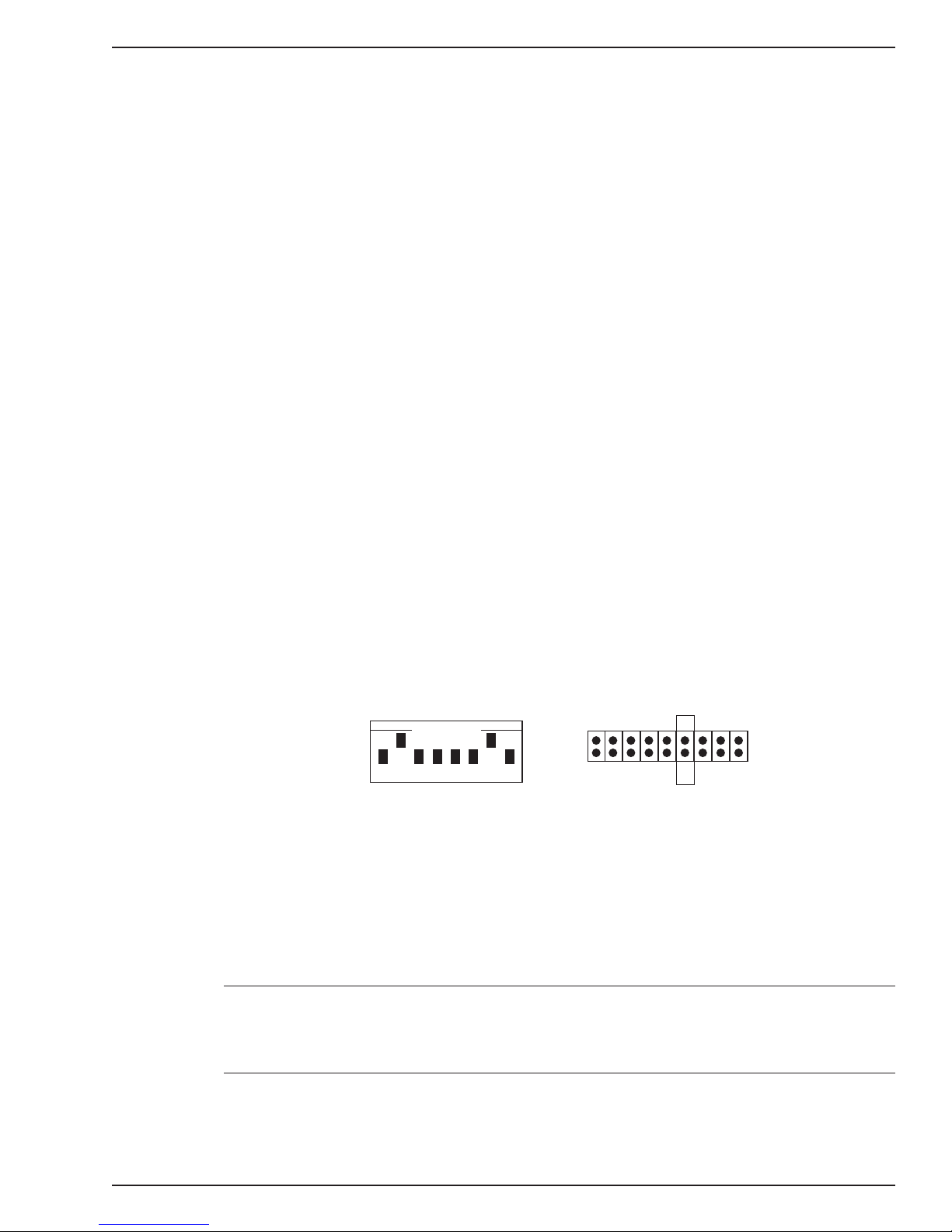
7. Check the settings of the I/O address switch and the IRQ jumper to ensure they are
set properly for your installation.
8. The default for the ISIHI-2S’s base I/O address is 210 hex. The default value for the
IRQ jumper is 10. Choose the IRQ value by covering the appropriate pins with the
jumper plug (supplied). Refer to the figure below, if needed. If your system requires a
different setting, or if you are installing multiple cards, refer to Appendix B for a table
of valid address settings.
OPEN
21435768
Record any changes you make to these settings for future reference and for software
installation (Chapter 3).
9. Install the ISIHI-2S card in the selected expansion slot in the same manner as any
other add-on card according to your computer’s documentation.
10. Fasten the retaining bracket to the computer chassis and replace the cover.
11. Connect the ISIHI-2S to your ISDN telelphone wall jack with the provided modular
telephone cable.
IRQ
71210 1511
45
3
2
Note: The ISIHI-2S communicates over ISDN lines. If you do not have a standard
modular wall jack near your computer, you should install one or have one installed by
your telephone company. In the US, installation kits and adapters are available wherever
telephones are sold.
12. Turn on the power to the computer. Now you are ready to install the software/drivers.
MultiModemISI Hybrid Series, ISIHI-2S 19
Page 20

Hardware Installation
20 MultiModemISI Hybrid Series, ISIHI-2S
Page 21

Software/Driver Installation
MultiModemISI Hybrid Series, ISIHI-2S 21
3
Page 22

Chapter 3—Software/Driver Installation
Introduction
This chapter contains general instructions for software/driver installation the following
operating systems:
• Windows NT
• Windows 95
• Novell
• SCO Open Server 5
This guide assumes installers have a thorough knowledge of their operating system and
the software installation process; therefore, it does not include every dialaog box or
option involved in installing and configuring the drivers.
The ISIHI-2S card ships with software/drivers for Windows NT, Windows 95, SCO Open
Server 5, and NetWare Connect (Novell) operating systems. This chapter guides you
through the installation of these drivers. The Multi-Tech Installation Script, used in the
UNIX operating system, is located on page 55 of this chapter.
As with all software, you should make a backup copy of the diskette you received and
use the copy for the installation. If you received a 3½" diskette, the capacity is 1.44 MB.
Consult your system manual for instructions on disk copying. Also, if you have a numeric
keypad, and you intend to use it for the installation process, make sure
Num Lock
is on.
Installing a device driver consists of modifying your system. For this reason, only the
super user
login as the root, you must find the person in your organization who has this
authorization (i.e., password). To begin the driver installation, login as root. Then
proceed with the appropriate section.
(system administrator) is allowed to perform the installation. If you cannot
22 MultiModemISI Hybrid Series, ISIHI-2S
Page 23
Chapter 3—Software/Driver Installation
Installing ISIHI-2S Drivers in Windows NT
1. Click Start, Settings, Control Panel, and then double-click the Add/Remove
Programs icon.
2. The Add/Remove Program Properties dialog box appears. In the Install/Uninstall
tab, click Install.
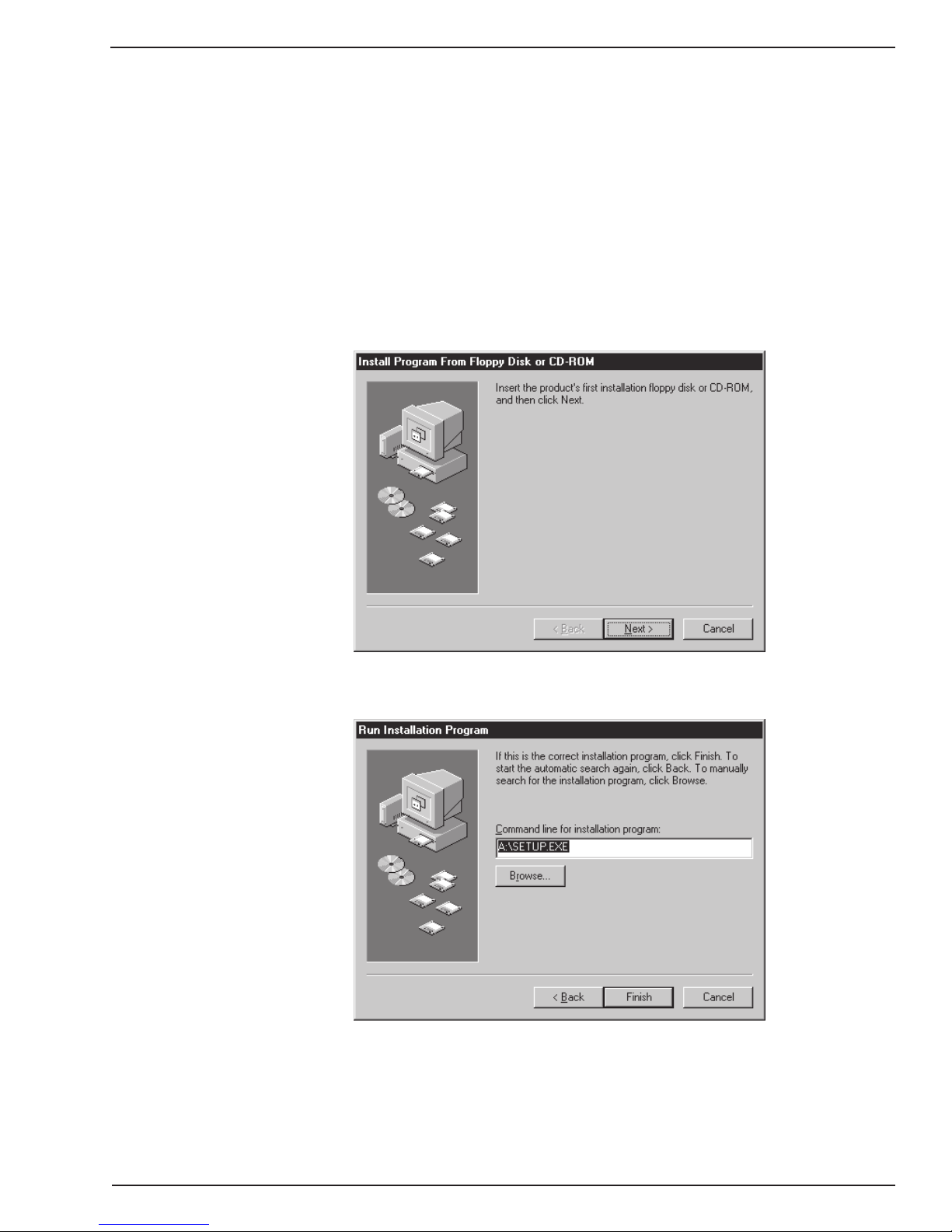
3. The Install Program From Floppy Disk or CD-ROM dialog box appears. If installing
from diskette, insert the diskette labeled MultiModem ISI Driver for Windows NT in
the disk drive. Then click Next.
(If installing from a network location, connect to it. Note drive. You may need it later if
you run Setup again.)
4. When the Run Installation Program dialog box appears, click Finish and the driver
installs.
MultiModemISI Hybrid Series, ISIHI-2S 23
Page 24
Chapter 3—Software/Driver Installation
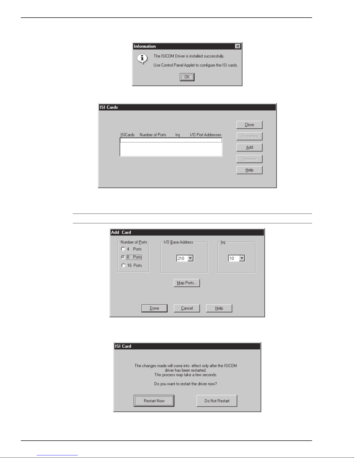
5. When the Information dialog box below appears, click OK.
6. The ISI Cards dialog box appears. Click Add.
7. The Add Card dialog box appears, displaying defaults—Ports: 8, I/O Base: 210, and
IRQ: 10. Click Done and then Close.
Note: The ISIHI-2S contains 8 ports. Make sure the default is 8.
8. The ISI Card dialog box appears. Click Restart Now to restart the driver. Then click
OK.
The ISI driver now is installed and you are ready to install the TAs and modems to the
COM ports.
24 MultiModemISI Hybrid Series, ISIHI-2S
Page 25
Chapter 3—Software/Driver Installation
Installing Terminal Adapters and Modems to COM Ports in Windows NT
To install
terminal adapters
:
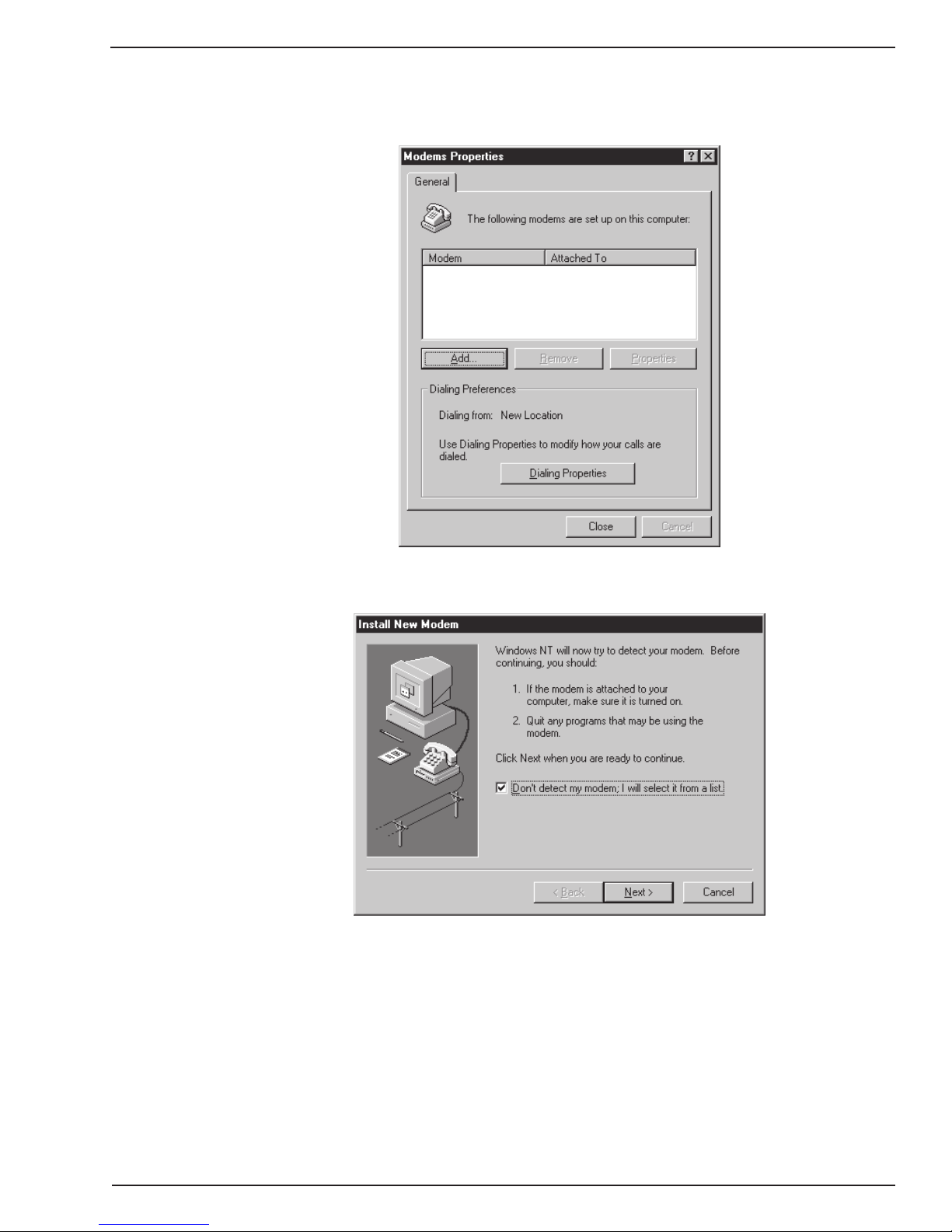
1. In the Control Panel, double-click the Modems icon.
2. The Modem Properties dialog box appears. Click Add.
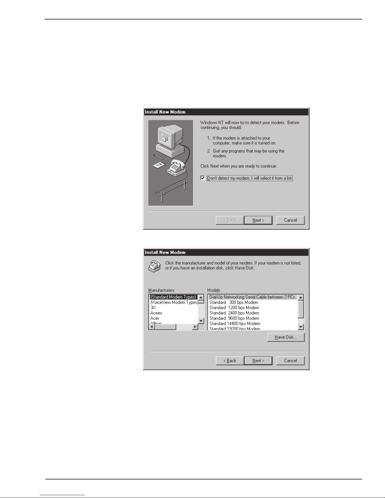
3. The Install New Modem dialog box appears. Check the box marked Don’t detect
my modem; I will select it from a list and click Next.
4. The Install New Modem dialog box appears. Click Have Disk.
MultiModemISI Hybrid Series, ISIHI-2S 25
Page 26
Chapter 3—Software/Driver Installation
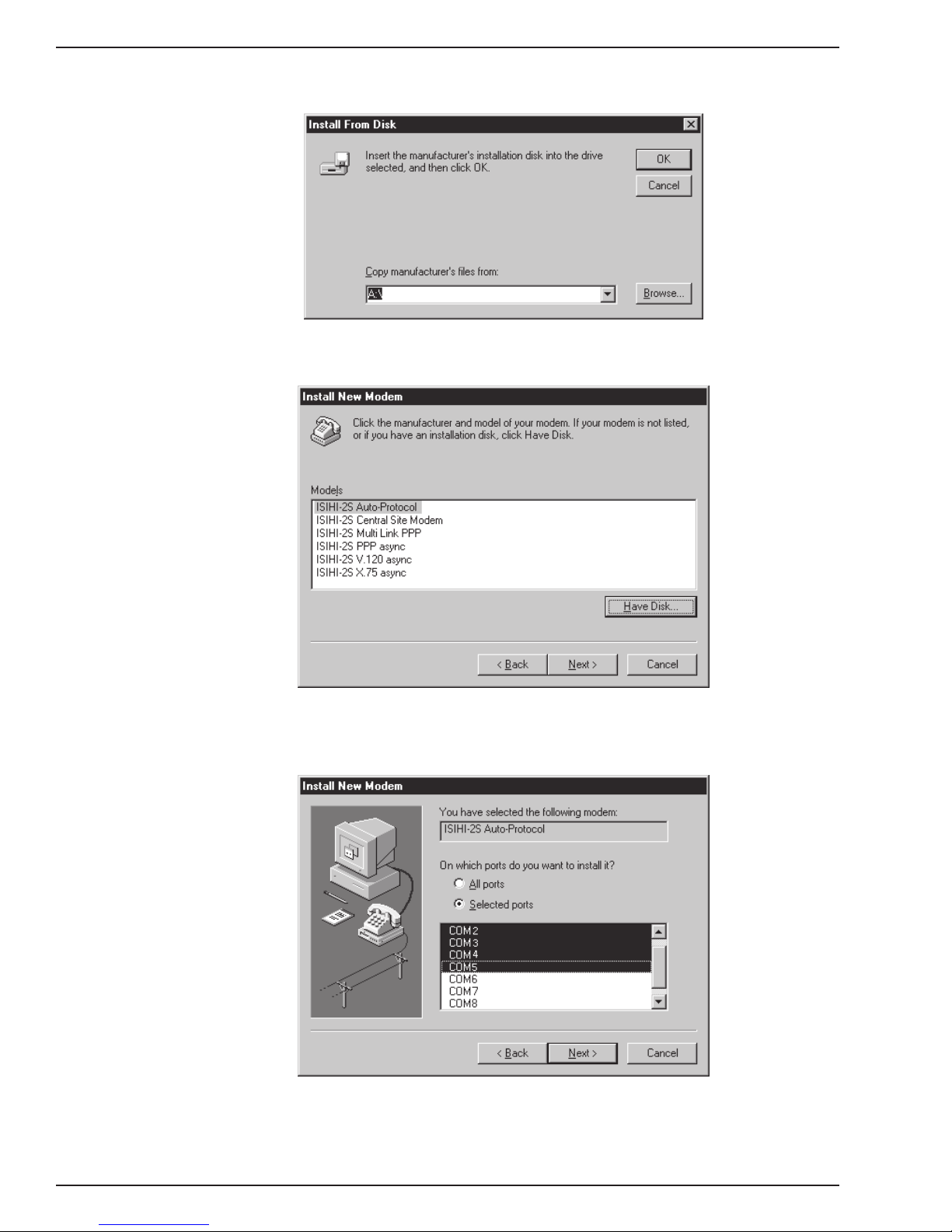
5. The Install From Disk dialog box appears. Click OK (diskette should still be in drive).
6. The Install New Modem dialog box appears. From the Models list, select a protocol
(depending on your application) for the terminal adapters. Then click Next.
7. The Install New Modem dialog box appears. Select the first four COM ports; then
click Next. The terminal adapters (screen displays modems) install to the selected
COM ports.
8. After the terminal adapters are installed, click Finish to return to the General tab
where you can view COM port assignments (and make changes if necessary). You
now are ready to install the modems.
26 MultiModemISI Hybrid Series, ISIHI-2S
Page 27
Chapter 3—Software/Driver Installation
To install
modems
:
1. In the General tab, click Add.
2. The Install New Modem dialog box appears. Check the box marked Don’t detect
my modem; I will select it from a list. Then click Next.
MultiModemISI Hybrid Series, ISIHI-2S 27
Page 28
Chapter 3—Software/Driver Installation
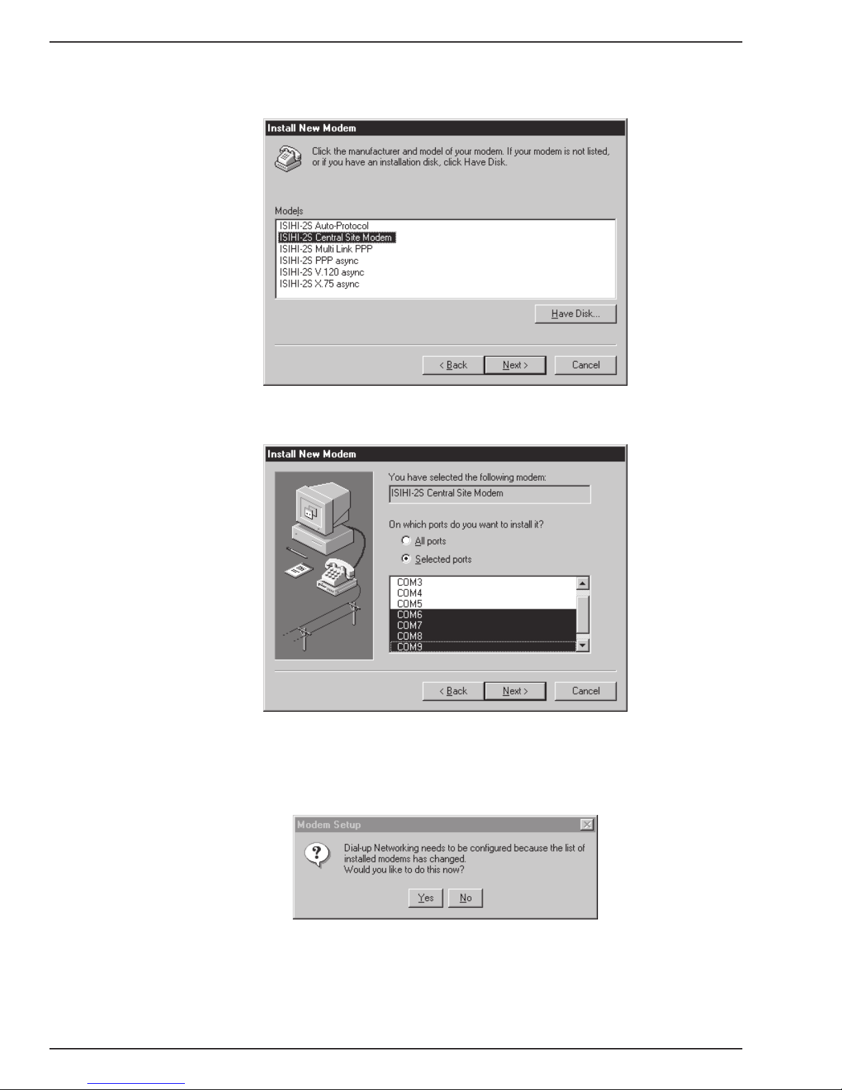
3. The Install New Modem dialog box appears. From the Models list, select Central
Site Modems for the modems. Then click Next.
4. Select the next four COM ports; then click Next. The modems install to the selected
COM ports.
5. After the modems are installed to the ports, click Finish to return to the General tab
where you can view COM port assignments (and make changes if necessary).
6. Close the Modem Properties dialog box. The message below appears asking if you
want to configure dial-up networking. Click Yes.
28 MultiModemISI Hybrid Series, ISIHI-2S
Page 29

Chapter 3—Software/Driver Installation
7. The Remote Access Setup dialog box appears. Click Add.
8. Each COM port appears in a separate Add RAS Device dialog box. To add the
highlighted device, click OK.
9. The Remote Access Setup dialog box displays again. Repeat steps 7 and 8 until
until all devices are added.
10. When all devices are added, click Continue.
MultiModemISI Hybrid Series, ISIHI-2S 29
Page 30

Chapter 3—Software/Driver Installation
11. When the message below appears, click Yes.
The ISI Cards icon appears in the Control Panel and you now are ready to configure
the terminal adapter. Go to page 44.
Removing the Driver
1. Click Settings, Control Panel; then double-click Add/Remove Programs.
2. From the list box, select ISICOM Driver.
3. Click Add/Remove and follow screen instructions.
30 MultiModemISI Hybrid Series, ISIHI-2S
Page 31

Chapter 3—Software/Driver Installation
Installing ISIHI-2S Drivers in Windows 95
1. Click Start, Settings, Control Panel, and then double-click the Add/Remove
Programs icon.
2. The Add/Remove Program Properties dialog box appears. In the Install /Uninstall
tab, click Install.
3. The Install Program From Floppy Disk or CD-ROM dialog box appears. If installing
from diskette, insert the diskette labeled MultiModemISI Driver for Windows 95 &
Netware AIO in the disk drive. Then click Next. (If installing from a network location,
connect to it. Note drive; you may need it later if you run Setup again.)
4. The Run Installation Program dialog box appears. In the command line, enter
A:\WIN95\Setup.exe. Click Finish and the driver installs.
MultiModemISI Hybrid Series, ISIHI-2S 31
Page 32

Chapter 3—Software/Driver Installation
5. The Welcome dialog box appears. Click Next.
6. The ISI Card Port Count dialog box appears. Make sure the 8 Ports option is
selected; then click Next.
32 MultiModemISI Hybrid Series, ISIHI-2S
Page 33

Chapter 3—Software/Driver Installation
7. The Destination Directory dialog box appears. Click Next.
8. The Start Copying Files dialog box appears. Click Next.
MultiModemISI Hybrid Series, ISIHI-2S 33
Page 34

Chapter 3—Software/Driver Installation
9. The ISI Driver Setup dialog box appears. Click OK.
10. The ISI Driver Setup dialog box appears instructing you to set the base address and
IRQ for the card. Click OK.
11. The Systems Properties dialog box appears. In Device Manager, double-click
MultiT ech ISI Card in Multiport to change settings.
34 MultiModemISI Hybrid Series, ISIHI-2S
Page 35

Chapter 3—Software/Driver Installation
12. The MultiTech ISI Card Properties dialog box appears. Click Resources. Then click
Set Configuration Manually.
13. In the Resources settings: list, select Input/Output Range; then click Change
Setting.
MultiModemISI Hybrid Series, ISIHI-2S 35
Page 36

Chapter 3—Software/Driver Installation
14. The Edit Input/Output Range dialog box appears. Click the arrows (up or down) to
select the value that matches the ISIHI-2S card’s I/O address. (If you used the default
I/O address, this value is 210. Otherwise, refer to the settings you recorded on page
18.) When finished, click OK to return to the Resources settings: list.
15. In the Resources settings: list, select Interrupt Request; then click Change
Setting.
36 MultiModemISI Hybrid Series, ISIHI-2S
Page 37

Chapter 3—Software/Driver Installation
16. The Edit Interrupt Request dialog box appears. Select the value that matches the
ISIHI-2S card’s IRQ. (If you selected the default IRQ, this value is 10. Otherwise,
refer to the settings you recorded on page 18.) Then click OK to return to the
Resources settings: list.
17. The MultiTech ISI Card Properties dialog box appears. If settings are correct, click
OK.
MultiModemISI Hybrid Series, ISIHI-2S 37
Page 38

Chapter 3—Software/Driver Installation
18. When the System Settings Change dialog box appears, click Yes.
Drivers now are installed. You are ready to install the TAs and modems to the COM
ports.
38 MultiModemISI Hybrid Series, ISIHI-2S
Page 39

Chapter 3—Software/Driver Installation
Installing Terminal Adapters and Modems to COM Ports in Windows 95
To install
terminal adapters
:
1. In the Control Panel, double-click the Modems icon.
2. The Modem Properties dialog box appears. Click Add.
3. The Install New Modem dialog box appears. Check the box marked Other and click
Next.
4. The Install New Modem dialog box appears again. Check the box marked Don’t
detect my modem; I will select it from a list. Click Next.
MultiModemISI Hybrid Series, ISIHI-2S 39
Page 40

Chapter 3—Software/Driver Installation
5. The Install New Modem dialog box appears. Insert the diskette labeled MultiModem
ISI Driver for Windows 95 & Netware AIO and click Have Disk.
6. The Install From Disk dialog box appears. In the text box, enter
A:\WIN95\isihimdm.inf and click OK.
7. The Install New Modem dialog box appears. From the Models list, select a protocol
(depending on your application) for the
terminal adapters
. Then click Next.
40 MultiModemISI Hybrid Series, ISIHI-2S
Page 41

Chapter 3—Software/Driver Installation
8. The Install New Modem dialog box appears. Select the first four COM ports; then
click Next. The terminal adapters (screen displays
modems
) install to the selected
COM ports.
9. After the terminal adapters install, click Finish to return to the General tab where you
can view COM port assignments (and make changes if necessary). You now are
ready to install the modems.
MultiModemISI Hybrid Series, ISIHI-2S 41
Page 42

Chapter 3—Software/Driver Installation
To install
modems
:
1. In the General tab, click Add.
2. The Install New Modem dialog box appears. Check the box marked Don’t detect
my modem; I will select it from a list. Then click Next.
42 MultiModemISI Hybrid Series, ISIHI-2S
Page 43

Chapter 3—Software/Driver Installation
3. The Install New Modem dialog box appears. From the Models list, select Central
Site Modems for the
modems
. Then click Next.
4. The Install New Modem dialog box appears. Select the next four COM ports and
click Next. The modems install to the selected COM ports.
5. After the modems install to the ports, click Finish to return to the General tab where
you can view COM port assignments (and make changes if necessary). Now you are
ready to configure the terminal adapters.
Removing the Driver
1. Click Settings, Control Panel, and then double-click Add/Remove Programs.
2. From the list box, select ISICOM Driver.
3. Click Add/Remove and follow screen instructions.
MultiModemISI Hybrid Series, ISIHI-2S 43
Page 44

Chapter 3—Software/Driver Installation
Configuring the Terminal Adapter
Before you connect the ISIHI-2S to your network terminator, you must configure it to
match your ISDN service and the remote TA. Y ou can use any of the following methods:
•I
SDN TA Configuration Utility
Windows NT, version 4.0 operating systems.
•
ConfigMenu
ANSI compatible terminal or data communication program that includes VT100/ANSI
terminal emulation.
•
A T Commands
registers. Enter these commands in your data communication program’s terminal
mode. AT commands are described in detail in the Chapter 4.
Before You Start
Consider the following choices before configuring your TA. Then record your choices
here and refer to them during configuration.
—recommended for computers with DOS or Windows 3.x and a VT100/
—allow you to fine tune TA operation with AT commands and S-
—recommended for computers with Windows 95 and
Network Configuration
•
Network Switch T ype _____________________
Select the network switch type your ISDN service uses at its local central office. You
can set the TA to NET3, AT&T 5ESS, NT DMS-100, or US National ISDN-1. If you don’t
know the switch type, get the information from your ISDN service provider.
A T command: !CO=
•
Data TEI _______________________________
The Data TEI is the TEI (terminal endpoint identifier) assigned to the data channel. You
can select Auto TEI, a fixed TEI, or Disable. A TEI is a number used by the central
office switch to uniquely identify each device that is connected to the network. When it
uses dynamic TEI assignments (Auto TEI), the central office switch assigns a TEI each
time the TA connects to the network. However, the ISDN service provider may assign a
fixed TEI at subscription time, in which case you must configure the TA with the fixed
TEI number. You also can disable the channel, which may be useful when multiple TAs
are attached to a network terminator bus. AT command: !D3=
•
Voice TEI ______________________________
The Voice TEI is the TEI assigned to the voice channel. You have the same choices as
for Data TEI: Auto TEI, fixed TEI number, or Disable. A T command: *!D3=
•
SPIDs and DNs __________________________
The TA must be configured with the Service Profile Identifier (SPID). The SPID,
assigned by the local phone company, is for the specific BRI line where TA is attached.
The SPID field is empty prior to configuration. AT command: A T!C6= and AT*!C6
The Directory Number (DN) is the phone number another user would call to contact this
T A once it is attached to the ISDN. AT commands: AT!N1= and AT*!N1=
Note: SPIDs only apply for North American switch types.
44 MultiModemISI Hybrid Series, ISIHI-2S
Page 45

Chapter 3—Software/Driver Installation
Call Control Configuration
•
Persistent DTR Dialing ____________________
A high DTR (Data Terminal Ready) signal on the serial port indicates that your
computer or terminal is ready to communicate with your TA. DTR normally goes high
when a communication program starts or is ready to dial. Persistent DTR dialing
enables the TA to automatically redial the number stored in memory location 0
whenever DTR is high, and the serial port does not have an active call. You can enable
or disable this feature. AT command: $D
•
Auto Answer Data Calls ______________ Rings to Answer _____________
Select Auto Answer if you want the TA to automatically answer all incoming data calls
(option does not affect analog port). The Rings to Answer number ( range: 1—255)
selects number of rings the TA waits before answering an incoming call. Default: 1 ring.
A T command: S0=
•
Dialing Method __________________________
Select either the Enbloc or the Overlap dialing method for use when establishing a data
call. Your ISDN provider determines the dialing method. The enbloc method is used for
most ISDN dialing; however, you can select the overlap method if you are working with
a private network. AT command: %A97=
•
Data Protocol ___________________________
The data protocol, also known as the B-channel protocol and the rate adaption
protocol, is the language spoken over each 64 Kbps channel between two ISDN
devices. The devices on both ends of the ISDN link must use identical protocols. AT
command: !Z
V.120 Protocol
X.75 Protocol
—provides rates up to 64000 bps on each B channel.
—packet-switched network protocol for international use. Layer 2
portion commonly is used as a rate adaption protocol.
PPP Protocol
Stored Numbers _________________________
•
—provides rates up to 64 Kbps per channel.
The TA can optionally store as many as 10 phone numbers, up to 20 characters each.
A T command: &Z=
•
Dialing Stored Numbers ___________________
The TA can dial a number previously stored in directory number n using the &Zn=x
command. AT command: e.g., DS3
MultiModemISI Hybrid Series, ISIHI-2S 45
Page 46

Chapter 3—Software/Driver Installation
To Configure the Terminal Adapter
You can configure TAs with ISDN TA Configuration utility, ConfigMenu, or with AT
commands. Instructions for all three are provided in this section.
ISDN TA Configuration Utility
1. Before you start the ISDN TA Configuration utility, disconnect the ISIHI-2S by
removing the RJ-45 cable from the ISDN jack.
2. Insert the diskette labeled Config Utility (ISDNTA). Click Start, Programs, and then
the ISDN TA Configuration Utility icon.
3. The W elcome dialog box appears. Click Next.
4. The Searching for TA dialog box appears. Click Next.
46 MultiModemISI Hybrid Series, ISIHI-2S
Page 47

Chapter 3—Software/Driver Installation
5. The Configuration dialog box appears. Refer to your network configuration notes in
Before You Start
as you enter information to configure both TAs. If you have
questions about choices, click Help. After entering information in each dialog box,
click Next.
6. The Data Protocol Setup dialog box appears. Referring to you network configuation
notes, enter the appropriate information; then click Next.
MultiModemISI Hybrid Series, ISIHI-2S 47
Page 48

Chapter 3—Software/Driver Installation
7. The SPID dialog box appears. Referring to your network configuration notes, enter
the appropriate information; then click Next.
8. In the Save Configuration dialog box, enter a name to store the configuration. Then
click Next.
48 MultiModemISI Hybrid Series, ISIHI-2S
Page 49

Chapter 3—Software/Driver Installation
9. To load the configuration, click Next in the Load Configuration dialog box.
10. Then click Finish in the Configured dialog box.
The first TA now is configured.
11. Click Back to return to the Configuration dialog box and repeat steps 5 through 10
to configure the remaining TA(s). If you install multiple ISIHI-2S cards in the same
PC, you must configure two TAs per card installed. For example, if you install four
ISIHI-2S cards in one PC, you have to configure eight TAs (two per card).
12. After both TAs are configured, close the ISDN TA Configuration utility and connect to
the network again.
MultiModemISI Hybrid Series, ISIHI-2S 49
Page 50

Chapter 3—Software/Driver Installation
ConfigMenu Configuration Utility
Use the ConfigMenu configuration utility with computers using DOS or Windows 3.x
operating systems. ConfigMenu is installed in the TAs as part of the firmware.
To use ConfigMenu:
1. Start a data communication program and select the COM port where the TA is
connected.
2. In the communication program dialog box, type AT@Config and press ENTER.
ConfigMenu’s Main Menu appears (see screen below).
3. T o select menu item, type its number and press ENTER. A submenu then appears
where you can make selections. At the lowest level, you can change a configuration
option by selecting a number or typing a value and pressing ENTER.
4. When you finish, close ConfigMenu.
5. Use the &W command to save your new configuration and to load it automatically
when the TA is turned on.
50 MultiModemISI Hybrid Series, ISIHI-2S
Page 51

ConfigMenu Menus
Chapter 3—Software/Driver Installation
Network Configuration Menu
data and voice TEIs, and data and voice MSNs. When you finish, select Save Network
Configuration to save your work.
Call Control Configuration Menu
Options include Auto Answer, Rings to Answer, Dialing Method, and Persistent DTR
Dialing.
Data Protocols Menu
Stored Numbers Menu
each). Stored number 0 is the phone number that will be dialed if persistent DTR dialing
is enabled.
Port Control Configuration Menu
responds to control signals on the serial interface.
Help Menu
the ISIHI-2S’s firmware version numbers.
AT Commands
You can configure the terminal adapters using AT commands, just as you would
configure an analog modem. Use this method if you prefer to work with AT commands or
if you have a special requirement not addressed by either of the configuration utilities.
—configures network parameters such as switch type,
—changes how the TA originates and answers calls.
—changes the rate adaption protocol used by the TA.
—stores up to ten phone numbers ( maximum of 20 characters
—configures TA’s serial port, including how TA
—provides assistance in navigating through the TA menu system or viewing
To configure the T As with AT commands:
1. Disconnect the ISIHI-2S from the network (remove RJ-45 cables from ISDN jacks).
2. Start a data communication program and select the first and third COM ports to be
configured.
3. Referring to your notes made in Before You Start, enter AT commands in the terminal
window of the data communications program.
4. When you finish, use the &W command to save your new configuration and to select
it to load automatically when the ISIHI-2S is turned on.
5. Close the data communications program and reconnect the TA to the network
terminator.
For more information on AT commands, refer to Chapter 4.
MultiModemISI Hybrid Series, ISIHI-2S 51
Page 52

Chapter 3—Software/Driver Installation
NetWare Connect (Novell) Driver Installation
Multi-Tech Systems provides AIO drivers for the ISIHI-2S, so it can function with Novell
compatible asynchronous applications (e.g., NetWare Connect). The AIO driver is simply
an NLM (NetWare Loadable Module) that runs on the file server. Drivers must be loaded
on the file server where the board is installed. Drivers can be loaded from the file server’s
console prompt or incorporated for autoloading in the AUT OEXEC.NCF file.
To install the Multi-T ech AIO driver, copy the file AIOISIX.NLM to the system directory of
the file server from a workstation on the network. To copy , use the following command:
COPY A:\AIOISIX.NLM F\:SYSTEM
To load the driver, go to the system or PC console (where the ISIHI-2S is installed) and
enter the following at the prompt:
LOAD AIOISIX [port=W] [int=X] [name=Y] [note=Z]
W is the hexadecimal I/O port address for the ISIHI-2S. The ISIHI-2S occupies the
next 15 I/O addresses on the bus. That is, if you specify the address 210 hex, then
the ISIHI-2S occupies addresses from 210 hex to A hex (total of 16 addresses).
X is the interrupt (IRQ) vector number for the ISIHI-2S. The ISIHI-2S can be set for
IRQ vectors 10, 1 1, 12 & 15.
Y sets the ISIHI-2S board name.
Z overrides the default node ID number for the ISIHI-2S.
Note: All these parameters are optional. If none are supplied, the AIO driver assumes the
default I/O address and IRQ values and tries to load the driver.
IRQ Jumpers
Setting IRQs consists of installing the IRQ jumper on the two pins that indicate the
interrupt vector. For example, IRQ10 is chosen in the configuration below.
234 5710111215
: : : : : [:] : : :
Error Messages
1.
*Error: An ISIHI-2S does not seem to appear at address X*
The driver could not find the ISI residing at the address X. Make sure there is no
other device in your system at the same I/O address and that the ISI is seated
properly in the system slot.
*Error: ISIHI-2S rejected the load header*
2.
*Error: ISIHI-2S got out of sync*
*Error: ISIHI-2S verify failed at address X*
*Error: Expected X received Y*
*Error: Verify got out of sync*
All the above errors represent problems with the file server not being able to
communicate with the ISIHI-2S. Make sure no other device is residing in the system
at the same I/O address you chose for the ISIHI-2S. Power down the server and
make sure the ISIHI-2S is seated properly in the system slot. Power up the file server
and try to load the AIO driver again. If the problem persists, contact the Multi-Tech
Technical Support team.
52 MultiModemISI Hybrid Series, ISIHI-2S
Page 53

Chapter 3—Software/Driver Installation
T roubleshooting
Problem:
and connected a modem to a port on an ISIHI-2S. When I try to communicate with the
modem, I see the DTR of the modem being raised, but the modem does not respond to
my A T commands.
I loaded the driver at the file server console, then I started NetWare Connect
Solution:
in your system. Even though that particular device (for example, a mouse) is not
activated under NetWare, that device will still control the IRQ. Refer to your system’s
documentation to find out how to disable that device.
There might be an IRQ conflict between an ISIHI-2S and some other hardware
Configuring Ports for NetWare Connect
To set up NetWare Connect ports, enter LOAD NWCCON at the NetWare console
prompt. LOAD NWCCON opens the NetWare Connect Configuration Utility. Select the
appropriate menu options (modem type, speed, flow control, etc.)
Removing the Driver (Novell)
In Novell, remove file AIOISIX.NLM from the system directory and make the appropriate
changes to the
Autoexec.ncf
file.
MultiModemISI Hybrid Series, ISIHI-2S 53
Page 54

Chapter 3—Software/Driver Installation
SCO Open Server 5 Driver Installation
The installation utility provided by SCO is called custom. This section provides a brief
guide for opening the utility and installing the driver. The instructions below should be
used only on SCO Open Server 5 systems. When you have completed the steps below,
go to Multi-Tech Installation Script, which immediately follows this section.
1. If installing the driver from your default floppy drive, type custom and press ENTER to
open the custom utility. If using a nondefault drive, you must inform your system of
the disk drive from where you are doing the installation and the size and capacity of
the diskette(s).
2. Select Software and press ENTER.
3. The main menu displays a list of options. Press ENTER to select the highlighted item
(default): Install.
4. Select From comsco and press ENTER.
5. Make sure the driver diskette is in the floppy diskette drive and then press ENTER to
select the highlighted item (default): Floppy Disk Drive 0. The following message
appears: Examining media. Please wait …
6. The system recognizes you are installing the Multi-T ech Serial Card Driver and
prompts you to select the type of installation.
7. Select Full Installation and press ENTER to continue. These messages appear:
Extracting Files...
Executing Multi-T ech Serial Card Driver Init Script...
8. When installation finishes, this prompt appears:
Do you wish to continue ( y / n / q ):?
Type Y, press ENTER, and proceed with the next section,
Script
.
Multi-Tech Installation
54 MultiModemISI Hybrid Series, ISIHI-2S
Page 55

The Multi-Tech Installation Script
This section guides you through the Multi-Tech Installation Script for SCO and UNIXWare
systems. The script requests information such as how many boards you want to install,
what I/O address and IRQ values (interrupt requests) you have selected, and how many
pseudo devices you want to create for Multi_View utility. This information extracts the
necessary drivers, which will be linked with your system’s kernel.
1. The first screen requests the number of ISIHI-2S cards you are installing. If you have
more than one ISIHI-2S, use the chart on page 18 of this guide—Recommended
Base I/O Address and IRQ Values—to enter the appropriate values for each card.
Enter the number of cards and press ENTER.
2. The second screen requests the number of ports. Enter 8 and press ENTER.
3. The third screen requests the base I/O address you selected for the first card you are
installing. It is important to verify that the address you select for each ISI does not
overlap with existing devices or with another ISI. The ISI card uses the base I/O
address and the next fifteen addresses.
Note: If the I/O address you select conflicts with an existing device in your system,
you must remove the ISI driver and re-install it.
Chapter 3—Software/Driver Installation
Enter the base I/O address and press ENTER. For additional information, refer to the
online manual.
4. The fourth screen requests the IRQ value for this card. Verify that the IRQ you select
for each ISI does not overlap with existing devices or with another ISI. Type the
desired IRQ value and press ENTER.
Note: If you entered a number greater than 1 at the first screen, the previous three
screens reappear in sequence for each card you install. After you enter the
necessary information, installation continues.
5. The fifth screen requests you enter the number of pseudo devices to create for
Multi_View Utility. Enter the value and press ENTER.
Note: You must enter a minimum of 8 for each board installed.
6. The /dev directory holds device-information files used by the kernel to access the
hardware. When you add an ISI card, you must give the ISI ports unique names, so
they do not conflict with existing ports or other devices known to your system. If you
use an existing device name to identify your new ISI ports, the existing device is
deleted when the ISI port using its name is created.
The default base name for ISIHI-2S ports is ttyl. The default base name for printer
ports is prnl. If this is acceptable, type Y and press ENTER.
To change the base name, type N and provide a prefix of less than five characters.
The base name you select will be used for all ports on each card you install.
MultiModemISI Hybrid Series, ISIHI-2S 55
Page 56

Chapter 3—Software/Driver Installation
The following describes the format used in naming ISI ports:
Default device name and format: ttyl
ttyl basename
This prefix is applied to all ISI ports on all boards. Base names contain 1–4
characters.
b board number
V alues of 1 through 4, depending on the number of ISIs installed.
x port letter
V alues of A–H for ISI ports. (SCO UNIX values A-H indicate modem ports.)
Device base name selected: _________________
7. After you select a device base name, you are prompted for a printer base name. This
prefix identifies each port that supports a terminal with a printer attached to its
auxiliary port (for transparent printing). Select a unique base name or accept the
default of prnl (printer parameters are outlined in the Multi_Setup Utility section in
this guide).
Printer base name selected: _________________
8. The Multi_View utility initializes the multiple-page capability of terminals with multiple
pages of memory. You are asked how many pseudo devices (the total number of
pseudo devices you want to make available to the Multi_View utility) to create. This is
the total number of devices available to all Multi-Tech’s terminals. You can have a
maximum of 256 pseudo devices in your system.
9. The confirmation screen lists the values you selected. If these values are correct,
type Y and the installation process continues.
If there is an error in any of the values displayed, type N and the first screen appears.
You must then re-enter the information for each card.
When you accept the confirmation list (by typing Y), a series of messages displays
while the driver is being installed and the kernel rebuilt. When the display finishes,
press ENTER to continue. When Installation complete displays, press ENTER .
10. Select Host and press ENTER. Remove the diskette from floppy drive.
11. Select Exit and press ENTER.
12. T o reboot the system, enter the following commands:
Type sync and press ENTER.
Type sync again and press ENTER.
Type haltsys and press ENTER.
Driver installation for the ISI card now is complete.
56 MultiModemISI Hybrid Series, ISIHI-2S
Page 57

Activating Ports in SCO Open Server 5
SCO Open Server 5 provides a device database that monitors the activity of serial ports
through which users can log onto the host. If your ISI ports are used by terminals (e.g.,
to allow users to log onto your host), you must create an entry in the system’s device
database that furnishes specific information for the terminals that will be used on each ISI
port. The database is referenced each time a user attempts to log in. If there is no
database entry for a particular terminal, access to the host is denied.
1. Turn on your system, noting that the firmware for each ISIHI-2S loads successfully. If
the firmware for a given ISIHI card does not load, none of its ports will be accessible.
(If this happens, see Multi-Tech’s Administrative Utility section.)
2. The device database can be modified in two ways:
• To create terminal accounts with default settings, type /tcb/bin/ttys_update.
• To customize terminal entries, you must create them individually by entering the
system administrator’s shell (you must be logged in as the root user). To enter the
administrator’s shell, type sysadmsh and press ENTER.
3. Create device entries for each port of the ISI card by selecting the following from the
database menu: Accounts, T erminal, Create.
Chapter 3—Software/Driver Installation
4. Enter the complete name of the first device you want to create, substituting the base
name, board number, and port letter for the parameters: ttylb. Use a lower case x
value for local DTE (terminal) support and an upper case X value for modem control
for each port you want to enable. The port status can be altered later, but one setting
must be selected at this time.
5. Repeat this process for each port on each board you have installed. Record the
setting you select for each port.
6. Using device names created in the previous section, type the following command for
each port you want to activate: enable ttylbx
7. Repeat this command for each port you want to activate, using the lower case letter
for local terminal use or upper case for modem control.
Note: Only one of the options (e.g., modem control or local terminal access) should
be enabled for any port at one time. For example, you cannot enable ttyl1a and then
enable ttyl1A. To change the status of a port, disable the current status (disable
ttyl1a) and then enable it for the desired status (enable ttyl1A).
Removing the Driver (SCO Open Server 5)
To remove the Multi-Tech Serial Card Driver, you should enter the configuration utility
(e.g., custom for SCO Open Server 5) and follow the instructions to remove the entire
driver and rebuild the kernel without the ISI driver. If it is necessary to re-install the driver
due to I/O address or IRQ overlap, remove the driver first.
MultiModemISI Hybrid Series, ISIHI-2S 57
Page 58

Chapter 3—Software/Driver Installation
Multi_Setup Utility
This section guides you through the Multi_View Utility for SCO and UNIXWare systems.
While installing the ISIHI-2S drivers, you also install the Multi_View utility for multiple
page terminals. This section profiles the Multi_View utility and gives you the necessary
information to create a Multi_View information file.
Once installed, Multi_View can be opened by typing the following command:
Multi_View [options]
Multi_View initializes the multiple page capacity of terminals with multiple pages of
memory . While Multi_V iew works even on a dumb terminal (without multiple pages of
memory), your terminal should have multiple pages of memory and be capable of
retaining the position of the cursor on each page to get the proper effect.
Most state-of-the-art terminals have multiple pages of memory that allow them to switch
between sessions. Each page of memory available on the terminal allows it’s user to
establish another session on the host. The multiscreen capability of the terminal stores
screen information and cursor position for each session to a different page of memory.
Multi_View allows the host to process the session-switching hot keys and issue the
necessary escape sequence to the terminal so the appropriate page displays. Multi_View
treats each new screen opened by the user as a virtual screen and maintains mapping
between each virtual screen created and a page of memory on the terminal. The number
of virtual screens and pages of memory available are dependent on the terminal
emulation, the particular terminal being used, and the number of pseudo devices created
by the system administrator during installation.
In an ideal case, there can be as many virtual screens as there are pages of memory on
the terminal. If more virtual screens are specified than there are pages of memory , two
virtual screens can be mapped to a single page of memory where both sessions’s
screens display when that page of memory is recalled.
Once Multi_View successfully reads the terminal description and initializes the terminal,
the hot key sequence for
th
• Go to n
virtual screen
help
displays. The following hot keys are defined:
• Create new virtual screen
• Switch between current and previous screens
• Provide help on hot keys
• Quit Multi_View with an exit status of zero
• End Multi_View with a non-zero exit status
To define your own terminal capability database, refer to the
Description File Format
below. The following options are defined:
-h Prints the Help file. Multi_View uses the environment variable MTDSPLY to
choose the utility to display this file. If no such variable is found in the
environment, then Multi_View uses the
pg
utility .
-t Informs Multi_View to use a terminal description different from the one specified
by the TERM variable in the user environment.
-f Allows user to instruct Multi_View to read the terminal description from a different
file than the default description file. The default description file is
usr/bin/msfile
.
58 MultiModemISI Hybrid Series, ISIHI-2S
Page 59

Chapter 3—Software/Driver Installation
Description File Format
A description file may contain descriptions for multiple terminal types. Separate each
terminal entry by a blank line. The first line for each terminal contains the various names
by which that terminal is known. The three types of entries for each terminal emulation
are hot key entries, terminal escape sequences, and timing specifications.
Hot Key Entries
These entries have three columns. The first column specifies a mnemonic, which is
associated with a specific action taken by Multi_View . The mnemonics are listed below:
Mnemonic Description
vs Identifies the virtual screen entry. An entry is present for each virtual screen
that needs to be opened by Multi_View
sw Identifies the hot key sequence for switching between two virtual screens
cm Identifies the hot key sequence that instructs Multi_View to create a new
virtual screen
lm Identifies the hot key sequence for displaying help on the hot keys
qm Identifies the hot key sequence to exit Multi_View with a zero exit status
em Identifies the hot key sequence to exit Multi_View with a non-zero exit status
The second column contains the keystroke sequence to press to make the action
described by the mnemonic in the first column to take place.
The third column specifies the escape sequence sent by the terminal to Multi_View
when the key combination specified in column two is pressed.
In other words, these entries tell Multi_View that the terminal sends the escape sequence
specified in column three to Multi_View when the keystrokes specified in column two are
pressed and that Multi_View should take the action specified in column one whenever it
receives the characters specified in column three.
Terminal Escape Sequences
The terminal escape sequence entries describe the escape sequence to be sent to the
terminal. The first column contains a mnemonic, which are described below:
Mnemonic Description
ps Describes the escape sequence to send to the terminal to switch to the
appropriate physical page. The physical pages are numbered in the order
they are specified in the description file.
clear Specifies the escape sequence to clear the screen.
The second column has the character sequence to be sent to the terminal by Multi_View .
MultiModemISI Hybrid Series, ISIHI-2S 59
Page 60

Chapter 3—Software/Driver Installation
Timing Specification
The timing specification is the interval in tenths of a second that the utility waits before
checking for an escape sequence. The timing specification is defined below:
Mnemonic Description
time Specifies the interval, in units of 0.1 seconds, Multi_View waits while
reading characters before checking for escape sequences.
A sample file for the Wyse50 terminal is as follows:
wy50 wyse50 w50 ; line 1
vs Shift_F1 \001' \015 ; line 2
vs Shift_F2 \001a\015 ; line 3
sw Shift_F3 \001b\015 ; line 4
cm Shift_F4 \001c\015 ; line 5
cm Shift_F5 \001d\015 ; line 6
lm Shift_F6 \001e\015 ; line 7
qm Shift_F7 \001f\015 ; line 8
ps \033w0 ; line 9
ps \033w1 ; line 10
clear \033+ ; line 11
time 1 ; line 12
Line 1 Gives all the different names that the Wyse50 terminal is known.
Line 2 Specifies the virtual screen 0 settings. When the help screen displays,
<Shift>+<F1> displays for the virtual screen 0. The entry means the terminal
is going to send a string with the first ASCII character being the start of
header (01 Hex), second character a hyphen (-), and the last character a
carriage return <cr> when <Shift>+<F1> is entered on the terminal and
Multi_View is switched to the shell/process associated with virtual screen 0.
Line 3 Specifies the entry for virtual screen 1.
Line 4-8 Describes the hot keys to switch between the current and previous virtual
screens, create a new virtual screen, display the hot key help, quit Multi_View
with a zero exit status, and end Multi_View with a non-zero status
respectively.
Lines 9,10 Describes the physical pages on the terminal. The second string on each line
gives the escape sequence to be sent to the terminal to switch to the
appropriate physical page.
Line 1 1 Clear string to clear the screen.
Line 12 Specifies at least a 0.1 second wait in reading data before going ahead and
check for hot keys.
Each character in the escape sequence or hot key can be specified as an ASCII
character if it is printable. If not printable, it should be specified in an octal format with
leading 0s and preceded by a \. For example, an ASCII escape character can be
specified as \033.
Do not switch the screen while outputting as it may break the escape sequence sent to
the terminal. When there is more than one virtual screen, all outputs from the inactive
virtual screens are blocked. The virtual screen the user currently is working on is the only
active screen.
60 MultiModemISI Hybrid Series, ISIHI-2S
Page 61

The fullest potential of Multi_View is realized on a multiscreen terminal. However ,
Multi_View can be used on a dumb terminal that has only a single page of memory.
When there is only one page, the screen output is unavoidably garbled from different
virtual screen outputs.
Some important ASCII unprintable characters and their octal values are listed below.
SOH (^a) \001 STX (^b) \002
ETX (^c) \003 EOT (^d) \004
ENQ (^e) \005 ACK (^f) \006
ESC (^[) \033 Newline (NL) \012
Carriage
Return (CR) \015
Known limitations include:
• No null characters are allowed in the hot keys.
• No hot key can be a complete substring of another hot key.
Administration Utility
Chapter 3—Software/Driver Installation
Multi-Tech also provides an administrative utility called
Multi_Admin,
which aids in
troubleshooting Multi-Tech’s multiport boards. This section guides you through the
Administration Utility for SCO and UNIXWare systems. This interactive menu utility
displays various types of Multi-Tech’s multiport boards that can be installed in your
system. You specifically can observe the status and statistics of any installed multiport
board or any of its ports (e.g., MultiClusterU, ISI608, or ISIHI-2S).
This utility periodically updates the statistics and status information for selected boards
and/or ports. The displayed statistics are self-explanatory.
The -v option provides detailed information and can be used to analyze problems when
calling Multi-Tech’s technical support:
Usage: Multi_Admin [ -v ]
While you can view statistics and status on-screen, you also can store them to a log file
and fax the log to a technical support member at Multi-Tech to troubleshoot.
MultiModemISI Hybrid Series, ISIHI-2S 61
Page 62

Chapter 3—Software/Driver Installation
62 MultiModemISI Hybrid Series, ISIHI-2S
Page 63

AT Commands, S-Registers,
MultiModemISI Hybrid Series, ISIHI-2S 63
MODEM
and Result Codes
4
Page 64

Chapter 4—MODEM AT Commands, S-Registers, Result Codes
Modem
Modem AT Commands
The ISIHI-2S’s modems are controlled by instructions called
because the
commands (known as a
your keyboard while in terminal mode, or you can use communications software to issue
these commands automatically .
The modem is in command mode when it is not dialing or online. When it is in command
mode, you have access to a complete communications system that allows you to use
several features, including the basic AT command set described in this chapter. Using the
basic AT command set, you can enter phone numbers for automatic dialing, configure
modem options, and monitor telephone activity. In addition, you can command your
modem to perform advanced features such as error correction, data compression, speed
conversion, and more.
This chapter describes the modem’s operational modes, and shows you how to use each
of the modem’s AT commands. These commands and responses are compatible with all
systems and with all data communications software using the AT command set.
attention characters, AT
command string
, precede each command or sequence of
). You can send commands to the modem from
A T commands
, so called
Modes of Operation
The modem operates in two basic functional modes:
(There is also an in-between state,
command mode but not yet online.) When you turn on the modem, it is in command
mode and is ready to accept and respond to commands from your keyboard or software.
wait-for-carrier
command mode
, in which the modem is out of
and
online mode
.
The modem enters online mode after it dials, connects with another modem, and detects
a valid carrier signal. If it does not detect a carrier signal within the time frame controlled
in the modems by the S-register S7, the modem abandons the call and re-enters
command mode.
You can make the modem enter online mode without dialing by entering AT and then D
(dial) or A (force answer mode). The modem exits online mode if the carrier signal is lost
or intentionally dropped. When this happens, the modem hangs up and re-enters
command mode. By sending certain
can make it enter command mode without losing the carrier signal.
escape
characters to the modem while online, you
Command Structure
You can control a wide variety of modem operations and options when the modem is in
command mode. AT commands tell the modem to dial a number, to answer a call, to
operate at a certain speed, to use a certain compression technique, and many other
functions. AT commands consist of one or two letters, which may be preceded by an
ampersand (&), a percent character (%), or a slash character (\). The Q command, for
example, determines whether the modem returns result codes, while the &Q command
selects the asynchronous communications mode.
A parameter after a command (0, 1, 2, etc.) tells the modem which option to use. If you
do not specify a parameter, the modem assumes the 0 (zero) option. E, for example, is
the same as E0. You can issue several commands on a single line (a command string)
as long as the line does not exceed 40 characters.
64 MultiModemISI Hybrid Series, ISIHI-2S
Page 65

Chapter 4—MODEM AT Commands, S-Registers, Result Codes
Note: Each character in a command counts toward the 40 character command line
maximum. Example: Q1 is a single command, but it counts as two characters in the
command line.
Each command has a valid range of parameters; for example, &S can have only 0 or 1
as a parameter. Valid commands always generate an OK result code, and a few
generate an additional response such as a list of parameters. An invalid command such
as &S3, which has a parameter outside the valid range, generates an ERROR
result
code. Most commands have a default parameter that is enabled when the modem is
turned on or reset with the A TZ or AT&F command. Factory defaults are stored in read-
only memory (ROM) and cannot be changed. User-defined defaults can be stored in
nonvolatile random-access memory (NVRAM) and can be changed or deleted at will.
Command Editing
Always begin a command with the letters AT. Enter the entire command string in upper or
lower case, but do not mix cases within the command string. The A T command is not
executed until you press ENTER. Use the BACKSP ACE key to erase the previous
command character. It will not erase the AT characters once they are typed. If your
keyboard has no BACKSP ACE key, use CTRL+H. (You can change the character
recognized by the modem as BACKSP ACE to any other ASCII character by changing
register S5.)
Modem
Press CTRL+X to cancel an entire command that has been typed but not yet executed.
This also clears the command buffer. The effect is the same as backspacing the
command, only quicker.
The modem stores characters entered in a command in its command buffer until they are
executed by pressing ENTER. The command buffer’s capacity is 40 characters. The
attention characters (A T) do not count toward the 40-character command line maximum.
You may use spaces for increased readability when typing a command. Spaces are not
stored in the command buffer, and they do not count towards the 40-character command
line maximum. Special characters, such as hyphens and parentheses, are not allowed.
If you exceed the 40-character limit or type invalid characters, the command buffer is
automatically erased and an ERROR
message displays. You should retype the command
within the 40-character limit, using only the allowed characters.
The commands in this chapter are organized by function. Abbreviated commands are
listed below by function along with a short description and page numbers that refer to a
more detailed description, immediately following this list.
T opic Command Description Page
Dialing Action D Dial 67
H On-hook/off-hook
Dial Modifiers L Redial last number 67
P Pulse dialing
T Tone dialing
V Speakerphone mode
W Wait for new dial tone
, Dialing pause
; Return to command mode after dialing
! Flash on-hook
$ Detect call card tone
MultiModemISI Hybrid Series, ISIHI-2S 65
Page 66

Chapter 4—MODEM AT Commands, S-Registers, Result Codes
Modem
Topic Command Description Page
@ Quiet answer
^ Disable data calling tone transmission
Phone Number Memory &Z Store a phone number 70
DS Dial a stored number
Configuration Storage & Recall &W Store configuration 7 1
&F Load factory default configuration
Z Reset modem
&Y Select stored configuration on power-up
Modem Responses (Result Codes) E Echo command mode characters 72
Q Result codes: enable/disable
V Result codes: verbose/terse
\V Protocol result code
X Result codes and call progress
&Q Select asynchronous communications mode
%B View numbers in blacklist
Online Connection B Answer tone 74
C Carrier control
F Echo online data characters
&G Guard tones
-C Data calling tone
N Modulation handshake
\T Disable inactivity timer
Y Long space disconnect
RS-232 Interface Controls &C Carrier Detect control 76
&D Data Terminal Ready control
&S Data Set Ready control
Error Correction & Data Compression \N0 or &Q6 Non-error correction mode 77
\N3 Auto-reliable mode
\N2 Reliable mode
%C0 Data compression disabled
%C1 Data compression enabled
Immediate Action A/ Repeat last command 78
I Information request
&B V.32 auto retrain
&V View current configuration
Flow Control &M0 Asynchronous mode 79
&K0 or \Q0 Flow control disabled
&K3 or \Q3 Hardware flow control
&K4 or \Q1 XON/XOFF flow control
\X0 XON/XOFF no pass-through
&J Auxiliary relay control
\J Enable data buffer control
\G Modem port flow control
\K Set break control
+ES=6 Enable synchronous buffered mode
Escape Sequences +++AT<CR> Default in-band escape sequence 81
A Force answer mode
O Go back online
Diagnostics Speaker Settings &T Self-test commands 82
L Monitor speaker volume 82
M Monitor speaker mode
66 MultiModemISI Hybrid Series, ISIHI-2S
Page 67

Dialing Commands
Use dialing commands to dial and hang up.
s
D
Dial
s
= phone number
Default: none
Chapter 4—MODEM AT Commands, S-Registers, Result Codes
Modem
The letter
following it. For example, if you type A TD5551212<cr>, the modem dials the number
555-1212.
The ISIHI-2S modem supports several dialing methods. With the D command, you can
specify either pulse (A TDP) or tone (ATDT) dialing. You also can modify the dialing
command with several other characters that are explained in the
Commands
The modem also lets you select either smart (wait-for-dial-tone) dialing or blind dialing.
With smart dialing, the modem waits for and detects dial tones and busy signals. With
blind dialing, the modem works with timed pauses (determined by the value of register
S6), not dial tone and busy signal detection. See the X command for more information on
blind and smart dialing.
H
n
On-Hook/Off-Hook
n
= 0 or 1
Default: 0
Use the H command to make the modem hang up (go on-hook) or simulate the action of
picking up a telephone handset (go off-hook).
H0 (or H) hangs up the modem
H1 brings the line off-hook, just as if you had picked up the telephone handset.
D
in a command causes the modem to dial the telephone number immediately
Dial Modifier
section, later in this chapter.
It is not necessary to use the H1 command to bring the line off-hook when using the D
command. The modem automatically goes off-hook when you press E
the dial command.
Dial Modifier Commands
The dial string can include the digits 0 through 9, the pound sign (#), the asterisk (*), and
the letters
depend on the PBX manufacturer’s feature set and implementation. There are also
several command characters, called “dial modifiers,” that can be included within a dialing
command after the letter
dial sequence, automatic redials if a number is busy , and reverting to command mode or
switching to answer mode after dialing.
L Redial Last Number
Default: none
You can redial the last number dialed by entering L immediately following the dial
command (ATD). This command is handy if you encounter a busy signal and want to try
the call again.
A, B, C
NTER at the end of
, or D. The latter are used by some PBXs; the exact function will
D
. Their functions include pulse or tone dialing, pauses in the
MultiModemISI Hybrid Series, ISIHI-2S 67
Page 68

Chapter 4—MODEM AT Commands, S-Registers, Result Codes
Modem
P, T Pulse or Tone Dialing
Default: T
The ISIHI-2S’s modems dials numbers by using pulse dialing, tone dialing, or a
combination of both methods. Pulse dialing, used by rotary-dial telephones, uses the
timed opening and closing of a relay to encode the numbers. Tone dialing, used by pushbutton (touch-tone) telephones, uses dual tone multifrequency (DTMF) dialing.
P selects pulse dialing.
T selects tone dialing.
Insert P or T in the dialing command just before the digits you want to pulse- or tone-dial.
If neither pulse nor tone dialing is specified in the dial command, the modem uses
whatever method was used last.
Note: When your modem is first turned on or reset, it uses the tone dialing method
(which is the default), even if you do not include T in your dial command.
Examples:
To pulse-dial the number 555-1212, type ATDP5551212 and press ENTER.
To tone-dial the same number, type ATDT5551212 and press E
To call out of a PBX (switchboard) system where a
of the number has to be tone-dialed after pausing for a second dial tone, type
A TDP9,T5551212 and press E
NTER. (The comma causes a pause.)
V Switch to Speakerphone Mode
Inserting V into the dialing command causes the modem to switch to speakerphone
mode and dial the following number. Use ATH to hang up.
W Wait for New Dial Tone
Inserting W into the dialing command causes the modem to wait for another dial tone
before it resumes dialing. (It is not necessary to enter W at the beginning of the dialing
command.)
Note: Because the modem must be able to detect the dial tone for this command to
work, you also must select wait-for-dial-tone dialing with the X2 or X4 command.
, Dialing Pause
Enter a comma in the dialing string to make the modem pause while dialing. This pause
lasts two seconds (North American models) or four seconds (U.K. and International
models) for each comma entered. You can force longer pauses by entering multiple
commas, or you can change the length of the pause caused by a comma by setting
register S8 to any value from 0 through 255 seconds (North American), 4 through 7
seconds (U.K.) or 4 through 255 seconds (International).
NTER.
9
has to be pulse-dialed, and the rest
Note: Each comma in a dialing command counts as one of the 40 allowed characters.
68 MultiModemISI Hybrid Series, ISIHI-2S
Page 69

Chapter 4—MODEM AT Commands, S-Registers, Result Codes
; Return to Command Mode After Dialing
Enter a semicolon (;) as the last character of a dialing command to cause the modem to
return to command mode immediately after executing the command instead of waiting for
a carrier signal and going online.
For example, type A TDT5551212; to tone-dial the number and immediately go back into
command mode. The semicolon is useful when modem data transfer is not desired, as in
voice communications, or in applications using touch tones as a data entry method, such
as bank-by-phone.
! Flash On-Hook
Some switchboard systems react to a momentary on-hook condition. Insert an
exclamation mark into the dialing command to cause the modem to “flash” on-hook for
half a second, just as if you had pressed the switch hook on a telephone set for half a
second. (With U.K. models, the exclamation mark causes the modem to flash on-hook for
90 milliseconds.)
For example, to flash on-hook to transfer to extension 5678 after dialing the number 5551234, type A TDT5551234,,!5678. The commas cause a 4-second pause.
$ Detect Call Card Tone
Use the $ command to dial services that require you to enter your call card number after
a tone. The $ character in the dialing string causes the modem to pause and wait for an
A T&T call card
the rest of the dialing string. If it does not detect the tone within the time set in register
S7, the modem stops processing the dial string with a NO CARRIER message. Pressing
any key also terminates the $ command.
bong
or a 1600 Hz tone. When the modem detects the tone, it processes
Modem
@ Quiet Answer
Use the @ command to access a system that does not provide a dial tone. The @
command causes the modem to wait before processing the next character in the dialing
string. The wait is for one or more rings back followed by five seconds of silence.
For example, A TDT5551212@6313550 causes the modem to dial the first number (555-
1212), then wait for the time specified in register S7 for at least one ringback and five
seconds of silence. If the modem detects a busy signal, it hangs up and generates a
BUSY
result code. If it does not detect five seconds of silence, it hangs up and generates
a NO ANSWER result code. If it does detect five seconds of silence, it dials the second
number (631-3550).
^ Disable Data Calling Tone Transmission
Use the ^ command to disable the transmission of data calling tones. In the following
example, the ^ command is used to tone dial 555-1212 and suppress data calling tone
transmission. A TDT^5551212
MultiModemISI Hybrid Series, ISIHI-2S 69
Page 70

Chapter 4—MODEM AT Commands, S-Registers, Result Codes
Modem
Phone Number Memory Commands
The modem can store up to four telephone numbers in nonvolatile memory. You can
store the numbers with the &Z command and dial them with the ATDS command.
n=s
&Z
DS
Store a Phone Number
s
= phone number n= 0, 1, 2 or 3
Default: none
You can store a telephone number string in the modem’s phone number memory. You
can store four of these strings using the &Zn=s command. The memory locations are
N0
labeled
For example, the telephone number 1-612-555-1212 is stored at memory location N2 by
typing &Z2=16125551212 and pressing E
n
Dial a Stored Number
n
= 0, 1, 2, or 3
Default: none
You can automatically dial a telephone number that is stored in the modem’s number
memory by typing A TDS
stored at N2 by typing A TDS2 in terminal mode and pressing ENTER.
through N3.
NTER.
n
, where n = 0 through 3. For example, you can dial a number
70 MultiModemISI Hybrid Series, ISIHI-2S
Page 71

Chapter 4—MODEM AT Commands, S-Registers, Result Codes
Configuration Storage and Recall Commands
The ISIHI-2S stores parameters in two places. It stores factory default parameters in
read-only memory (ROM), and customized parameters in nonvolatile random access
memory (NVRAM). You cannot change the default parameters in ROM, but you can
change parameters in temporary memory and then store them in NVRAM as custom
settings. You can then recall the custom settings as if they were factory default settings.
&WnStore Configuration
n
= 0
Default: &W0
The &W command stores current AT commands and S-register values in nonvolatile
memory , so you won’t lose your custom settings when you turn off the modem or reset it.
&W0 (or &W) stores all current AT command and S-register values in nonvolatile random
access memory (NVRAM) and configures the modem so that it reads your custom
settings in NVRAM when the modem is turned on or when it is reset with the Z command.
The &F reset command will continue to read the factory default settings in ROM.
&F
n
Load Default Configuration
n
= 0
Default: &F0
Modem
n
Z
&Y
ISIHI-2S modems store factory default AT command settings and S-register values in
read-only memory (ROM); they store your custom AT command and S-register values in
nonvolatile random access memory (NVRAM).
The &F0 (or &F) command resets modem to the factory default values stored in ROM.
Reset Modem
n
= 0 or 1
Default: none
The Z command resets the modem to the configuration last saved by the &W command.
The default values come from the customized configuration in NVRAM.
Z1 is the same as Z0, and functions identically.
n
Select Stored Configuration for Hard Reset
n
= 0
Default: 0
This command is included for compatibility with applications that issue the &Y0
command. Modem functions are not changed.
&Y0 selects the profile stored at location 0 on power-up.
MultiModemISI Hybrid Series, ISIHI-2S 71
Page 72

Chapter 4—MODEM AT Commands, S-Registers, Result Codes
Modem
Modem Response (Result Code) Commands
ISIHI-2S modems can give responses to commands. The most common is OK, but the
modems also can alert you or your software to dial tones, busy signals, connection
speeds, and whether the connection is made with error correction or compression
result codes
E
Q
enabled. These responses are called
verbose (text).
n
Echo Command Mode Characters
n
= 0 or 1
Default: E1
Normally , when you type commands on the keyboard, the modem echoes the characters
back to the computer or terminal, which displays them on the monitor. Use the E
command to turn this feature off and on.
E0 disables the echo.
E1 enables the echo.
n
Result Codes Enable/Disable
n
= 0 or 1
Default: Q0
; they can be terse (numbers) or
Use the Q command to enable or disable result codes for applications such as computercontrolled auto dialing.
Q0 (or Q) enables result codes.
Q1 disables result codes for applications such as computer-controlled auto-dialing.
V
n
Result Codes (Verbose/Terse)
n
= 0 or 1
Default: V1
The V command controls whether the modem’s result codes display as text (
numeric (
result can display either as NO CARRIER or as the number 3.
V0 (or V) displays the modem’s result codes as a number.
V1 displays result codes as text.
Xn Result Codes and Call Progress Selection
n
= 0, 1, 2, 3, 4, 5, 6, or 7
Default: X4
The X command selects which result codes the modem provides in command mode and
determines whether the modem uses
the modem listens for dial tones and busy signals and responds to them. When it blind
dials, the modem ignores the signals and relies on timing instead.
terse
) messages. For example, if no carrier signal is detected after dialing, the
smart dialing
or
blind dialing
verbose
. When it smart dials,
) or
X0 causes the modem to blind dial. Instead of looking for a dial tone, it pauses for the
time set in register S6 and then dials regardless. Once a connection is made, it sends the
Bell 103 basic code CONNECT
72 MultiModemISI Hybrid Series, ISIHI-2S
to the terminal. It ignores any busy signals.
Page 73

Chapter 4—MODEM AT Commands, S-Registers, Result Codes
X1 causes the modem to blind dial, but in addition to the basic CONNECT code, it
provides extended codes consisting of the word CONNECT
connection (CONNECT 14400
modem does not recognize or respond to dial tones or busy signals.
X2 causes the modem to wait for a dial tone before dialing. If it does not detect a dial
tone within the time set by S6, the modem sends a NO DIAL TONE result code to the
terminal. In this mode, the modem provides extended result codes but does not respond
to busy signals.
X3 causes the modem to blind dial, but also it looks for a busy signal, and if it detects
one, it sends a BUSY
extended result codes, but it does not respond to dial tones.
X4 causes the modem to look for a dial tone and a busy signal, and respond with NO
DIALTONE or BUSY, as appropriate. It also provides extended result codes. It is the most
useful setting for most data communication programs and is the default setting.
X5 causes the modem to look for a dial tone and a busy signal, and response with NO
DIALTONE or BUSY, as appropriate. It also provides extended result codes. It is the most
useful setting for most data communication programs and is the default setting.
result code to the terminal. In this mode, the modem provides
or
CONNECT 28800, for example). In this mode, the
and the speed of the
Modem
&Q
X6 causes the modem to look for a dial tone and a busy signal, and respond with NO
DIALTONE or BUSY, as appropriate. It also provides extended result codes. It is the most
useful setting for most data communication programs and is the default setting.
X7 causes the modem to wait for a dial tone before dialing. If it does not detect a dial
tone within the time set by S6, the modem sends only the basic result code to the
terminal (ERROR, NO CARRIER, or CONNECT, for example). In this mode, the modem
does not respond to busy signals.
n
Asynchronous Communications Mode
n
= 0, 5, or 6
Default: &Q5
The &Qn command allows you to select the type of asynchronous communications mode
for your modem.
Note: These commands are the same as several of the \Nn commands, described later
in this chapter.
&Q0 selects asynchronous mode with data buffering. This is the same as \N0, non-error
correction mode with data buffering.
&Q5 selects error control with data buffering. This is the same as \N3, V.42/MNP autoreliable mode.
&Q6 selects asynchronous mode with data buffering. This is the same as \N0, non-error
correction mode with data buffering.
%B View Numbers in Blacklist
If blacklisting is in effect, this command displays the numbers for which the last call
attempted in the previous two hours failed. In countries that do not require blacklisting,
the ERROR result code appears.
MultiModemISI Hybrid Series, ISIHI-2S 73
Page 74

Chapter 4—MODEM AT Commands, S-Registers, Result Codes
Modem
Online Connection Commands
The following commands control the conditions of the online connection.
n
B
Answer T one
n
= 0, 1, 2, 3, 15, or 16
Default: B1 and B16
The B command selects the frequency the modem uses for its answer tone. (The answer
tone is the tone transmitted by the receiving modem to the calling modem, thus initiating
the
handshake
is no conflict, because all protocols use the Bell frequency of 2225 Hz. Lower speeds
require different frequencies.
B0 selects ITU-T V.22 mode when the modem is at 1200 bps.
B1 selects Bell 212A when the modem is at 1200 bps. This is a default.
B2 deselects the V.23 reverse channel.
B3 is identical to B2 in function. It also deselects the V.23 reverse channel.
B15 selects V.21 when the modem is at 300 bps.
between the two modems.) At higher speeds (2400 bps and above) there
B16 selects Bell 103J when the modem is at 300 bps. This is a default.
C
n
Carrier Control
n
= 1
Default: C1
The Cn command provides backward compatibility with some data communications
software.
C1 enables normal transmit carrier switching.
-C
n
Data Calling T one
n
= 0 or 1
Default: -C0
The data calling tone is a tone of a certain frequency and cadence, as specified in the
V.25 standards, which identifies whether it is remote data, fax, or voice. The frequency is
1300 Hz, with a cadence of .5 s on and 2 s off.
-C0 disables the V.25 data calling tone.
-C1 enables the V.25 data calling tone.
F Echo Online Data Characters
n
= 1
Default: F1
This command determines if the modem echoes data from the DTE. This command
provides backward compatibility with some data communications software.
F1 disables online data character echo.
74 MultiModemISI Hybrid Series, ISIHI-2S
Page 75

&GnGuard Tones
n
= 0, 1, or 2
Default: &G0 (models outside U.K.) or &G2 (U.K. models only)
The &G command controls the presence or absence of guard tones from the transmitter
when in answer mode at either 1200 or 2400 bps. Guard tones are used in Europe and
other areas to allow the modem to function in the telephone systems. Guard tones are
not used in the United States. U.K. models are locked at &G2 (1800 Hz guard tone).
&G0 disables ITU-T guard tones.
&G1 enables ITU-T 550 Hz guard tone.
&G2 enables ITU-T 1800 Hz guard tone.
N
n
Modulation Handshake
n
= 0 or 1
Default: N1
This command controls whether the local modem performs a negotiated handshake with
the remote modem at connection time, when the communication speed of the two
modems is different.
Chapter 4—MODEM AT Commands, S-Registers, Result Codes
Modem
\T
Y
N0 enables handshaking only at the communication standard specified by S37 and the
ATB command.
N1 always begins the handshake only at the communication standard specified by S37
and the ATB command, but allows fallback to a lower speed as the handshake proceeds.
This is the default.
n
Inactivity Timer
n
= 0
Default: \T0
The inactivity timer specifies the length of time, in minutes, that the modem waits before
disconnecting when no data is sent or received. This timer is specified in register S3. The
\T0 command disables the inactivity timer.
n
Long Space Disconnect
n
= 0
Default: Y0
When two modems are connected in reliable mode, a link disconnect request packet is
sent to request a disconnect. In non-error correction mode, there is no
request a disconnect. As a result, some
command is issued.
Y0 disables the modem’s use of the break signal.
garbage
may be received when a hang-up
polite
way to
MultiModemISI Hybrid Series, ISIHI-2S 75
Page 76

Chapter 4—MODEM AT Commands, S-Registers, Result Codes
Modem
RS-232 Interface Commands
These commands define how an ISIHI-2S modem uses and responds to standard RS232 signals.
n
&C
Carrier Detect Control
n
= 0 or 1
Default: &C1
The &C command lets you control the Carrier Detect (CD) signal on the RS-232/V.24
interface. This is a signal from the modem to your computer indicating that the carrier
signal is being received from a remote modem. Normally, CD goes
the modem detects a carrier on the communications link and
loses the carrier. By using &C, you can force the signal to stay high, or to drop
momentarily when the remote modem disconnects. This option is useful with some CBX
phone systems and mainframe front ends, which require CD to act in this manner .)
&C0 ignores the state of the carrier from the remote modem. CD is forced high.
&C1 allows CD to act normally—to go high when the modem detects a carrier, and to
drop when it loses the carrier.
drops
high
(turns on) when
(turns off) when it
&D
&S
n
Data T erminal Ready Control
n
= 0, 1, 2, or 3
Default: &D2
The Data Terminal Ready (DTR) signal on pin 20 of the RS-232/V.24 interface must be
high, or
the computer it is connected to is ready to communicate through the modem.
The DTR signal can also be used to cause the modem to reset to its default parameters,
as if you had given the modem an ATZ command.
&D0 (or &D) causes the modem to ignore the DTR signal and treat it as always on.
&D1 causes the modem, if in online data mode, to enter command mode, issue an OK
and remain connected when the DTR drops.
&D2 causes the modem to hang up when DTR drops while the modem is in online data
mode.
&D3 causes the modem to reset when DTR drops . It will also hang up if it is online.
n
Data Set Ready Control
n
= 0 or 1
Default: &S0
on
, in order for the modem to operate. A high DTR signal tells the modem that
Use the &S command to control the state of the Data Set Ready (DSR) signal on the RS232/V.24 interface. Normally, DSR follows CD. You can force the signal high or allow it to
act normally .
&S0 forces DSR high (on).
&S1 allows DSR to act normally , that is, to follow CD.
76 MultiModemISI Hybrid Series, ISIHI-2S
Page 77

Chapter 4—MODEM AT Commands, S-Registers, Result Codes
Error Correction and Data Compression Commands
You can configure modems to any of three different V .42 modes of operation (with or
without compression): non-error correction, auto-reliable, and reliable modes. You also
can turn data compression on or off.
\N
n
Error Correction Modes
n
= 0, 1, 2, 3, 4, 5, or 7
Default: \N3
Select the modem’s error correction mode using the \N command.
\N0 disables the modem’s V.42 error correction capabilities, and the modem functions as
a non-error correction modem with data buffering. This is the same as &Q6, described
earlier in this chapter.
\N1 causes the modem to function in direct mode.
\N2 enables reliable mode, in which the modem uses its V.42 error correction capabilities
for all transmissions. In reliable mode, the modem must be connected to a modem with
the V.42 MNP protocol.
Modem
\N3 enables auto-reliable mode. During the handshaking procedures at the start of the
online connection, the modem queries whether the other modem is using V.42 error
correction. If the modem determines that the other modem is using V.42, it switches itself
into reliable (V.42) mode and enables error correction. If it determines that the other
modem is not using V.42, the modem remains in non-error correction mode. (This is the
same as \N5 and \N7.)
\N4 enables reliable mode, in which the modem uses its V.42 error correction capabilities
for all transmissions. In reliable mode, the modem must be connected to a modem with a
V.42 protocol (MNP or LAP-M).
The V.42 standard includes MNP Class 3 and 4 and LAP-M error correction methods.
\N5 enables auto-reliable mode. During the handshaking procedures at the start of the
online connection, the modem queries whether the other modem is using V.42 error
correction. If the modem determines that the other modem is using V.42, it switches itself
into reliable (V.42) mode and enables error correction. If it determines that the other
modem is not using V.42, the modem remains in non-error correction mode. (This is the
same as \N3 and \N7.)
\N7 enables auto-reliable mode. During the handshaking procedures at the start of the
online connection, the modem queries whether the other modem is using V.42 error
correction. If the modem determines that the other modem is using V.42, it switches itself
into reliable (V.42) mode and enables error correction. If it determines that the other
modem is not using V.42, the modem remains in non-error correction mode. (This is the
same as \N3 and \N5.)
%C
n
Data Compression
n
= 0 or 1
Default: %C1
The %C command allows you to disable data compression. Data compression is
normally enabled.
%C0 disables V.42bis/MNP 5 data compression.
%C1 enables V.42bis/MNP 5 data compression.
MultiModemISI Hybrid Series, ISIHI-2S 77
Page 78

Chapter 4—MODEM AT Commands, S-Registers, Result Codes
Modem
Immediate Action Commands
Use immediate action commands to obtain information about AT commands and current
modem settings.
A/ Repeat Last Command
Default: None
Type A/ to repeat the previous command. Do not precede this command with AT or press
E
NTER to execute it.
n
I
&B
Information Request
n
= 0, 1, 2, 3, 4, or 9
Default: none
This command displays specific product information about your modem.
I0 or I returns the default speed and controller firmware version number. Use this
command to identify your modem’s firmware level before calling Multi-Tech Technical
Support. (This is the same as I3.)
I1 calculates and displays the ROM checksum (for example,
I2 performs a ROM check, calculates and verifies the ROM checksum, and displays the
results (
I3 returns the default speed and controller firmware version number. Use this command
to identify your modem’s firmware level before calling Multi-Tech Technical Support. (This
is the same as I or I0.)
I4 returns the firmware version for the data pump (for example,
I9 displays the country code (for example,
n
V .32 Auto Retrain
n
= 1
Default: &B1
OK
or
ERROR
).
NA Ver. 1
).
12AB
94
).
).
The &B1 command enables V.32 auto retrain.
&V View Current Configuration
Default: none
Use the &V command to display the active modem settings.
78 MultiModemISI Hybrid Series, ISIHI-2S
Page 79

Flow Control Commands
Flow control refers to techniques used by data terminal equipment and the modem to
pause and resume the flow of information between them. It prevents a device from
accepting more data than it can handle. The modem implements flow control in both
directions. When the modem halts the flow of data, it is called flow control. When the
computer halts the flow, it is called pacing.
n
&M
&K
Communications Mode
n
= 0
Default: &M0
The &M command enables asynchronous communications mode. This is the default.
n
Local Flow Control Selection
n = 0, 3, or 4
Default: &K3
The &K command allows you disable flow control and enable hardware or software flow
control.
Chapter 4—MODEM AT Commands, S-Registers, Result Codes
Modem
\Q
&K0 completely disables data flow control initiated by the modem. (This is the same as
\Q0.)
&K3 enables modem’s use of Clear to Send (CTS) signal on the RS-232/V.24 interface
to regulate data flow. When CTS drops, data flow is suspended until the signal goes
(on) again. This method of flow control works in conjunction with pacing (i.e., computerinitiated flow control), which uses the Request to Send (RTS) signal on the RS-232/V.24
interface. Hardware flow control cannot be enabled unless an active error correction
protocol is selected. This is the factory default setting. (This is the same as \Q3.)
&K4 enables XON/XOFF software flow control. XON/XOFF flow control is an in-band
method of data flow regulation. In-band data regulation means that the XON (^Q) and
XOFF (^S) characters are inserted into the stream of data rather than using separate
control lines. When an XOFF character is detected, the data stream is suspended until
an XON character is detected. If you issue the &K4 command to the modem, it will
respond to XON/XOFF pacing, and use XON/XOFF characters as its own method of flow
control to the computer. (This is the same as \Q1.)
The drawback to using this method of pacing is that some files may contain these
characters as part of the file data. If such a file is transferred using a modem with XON/
XOFF flow control enabled, the file transfer could fail due to indefinite suspension.
n
Local Flow Control Selection
n
= 0, 1, or 3
Default: \Q3
high
The \Q command allows you disable flow control and enable hardware or software flow
control.
\Q0 completely disables data flow control initiated by the modem. (This is the same as
&K0.)
\Q1 enables XON/XOFF software flow control. XON/XOFF flow control is an in-band
method of data flow regulation. In-band data regulation means that the XON (^Q) and
XOFF (^S) characters are inserted into the stream of data rather than using separate
MultiModemISI Hybrid Series, ISIHI-2S 79
Page 80

Chapter 4—MODEM AT Commands, S-Registers, Result Codes
Modem
control lines. When an XOFF character is detected, the data stream is suspended until
an XON character is detected. If you issue the &K4 command to the modem, it will
respond to XON/XOFF pacing, and use XON/XOFF characters as its own method of flow
control to the computer. (This is the same as &K4.)
The drawback to using this method of pacing is that some files may contain these
characters as part of the file data. If such a file is transferred using a modem with XON/
XOFF flow control enabled, the file transfer could fail due to indefinite suspension.
\Q3 enables modem’s use of Clear to Send (CTS) signal on the RS-232/V.24 interface to
regulate data flow. When CTS drops, data flow is suspended until the signal goes
(on) again. This method of flow control works in conjunction with pacing (i.e., computerinitiated flow control), which uses the Request to Send (RTS) signal on the RS-232/V.24
interface. Hardware flow control cannot be enabled unless an active error correction
protocol is selected. This is the factory default setting. (This is the same as &K3.)
n
\X
XON/XOFF Pass-Through
n
= 0
Default: \X0
When XON/XOFF pacing is active, the local modem has two options regarding the XON
and XOFF characters. It can respond to and discard the characters from the computer, or
it can respond to the characters and pass them through the data communications link to
the remote modem, thereby pacing the remote modem as well.
high
&J
\G
\J
&X0 causes the modem to respond to and discard the XON and XOFF characters. This
is the default.
n
Auxiliary Relay Control
n
= 0
Default: &J0
The &J0 command causes the auxiliary relay to remain open. It is never closed. This is
the default, and the only supported command format.
n
Modem Port Flow Control
n
= 0
Default: \G0
This command returns an
n
Data Buffer Control
n
= 0
Default: \J0
This command enables data buffer control. Serial port speed is independent of connect
speed.
\J0 enables data buffer control. This is the default, and the only supported command
format.
OK
for backward compatibility with some software.
80 MultiModemISI Hybrid Series, ISIHI-2S
Page 81

\K
n
Set Break Control
n
= 5
Default: \K5
This command determines how the modem processes a break signal received from the
local DTE during an online connection.
\K5 causes the modem to send the break to the remote modem in sequence with
transmitted data, non-destructive, non-expedited.
+ES=6 Enable Synchronous Buffered Mode
Default: none
This command allows an H.324 video application direct access to the synchronous data
channel. On underflow, the modem sends HDLC flag idle (0x7E) to the remote modem.
This special error correction mode is overridden by any of the following commands: &F,
&M, &Q, and \N. +ES=? shows the only allowed value.
Escape Sequences
Escape sequences are also known as escape codes. They are used to cause the
modem to enter command mode from online mode without disconnecting the call.
Chapter 4—MODEM AT Commands, S-Registers, Result Codes
Modem
+++AT<cr> In-Band Escape Sequence
If the modem is online with a remote modem, you can cause the modem to enter
command mode without disconnecting the call by typing an escape code. The default
escape code used by the modem is three plus signs (
to 10 command characters (most typically
escapes to command mode, executes the command (if any), and remains in command
mode. For example, to hang up the modem at the end of a call, type +++A TH <cr>.
A Force Answer Mode
You can use the A command to force the modem into answer mode. Type ATA when in
command mode to immediately bring your modem off-hook, out of command mode, into
online answer mode, and to cause it to transmit its carrier signal over the phone line. If
no responding carrier tone is received by your modem within forty-five seconds (or by the
time you have specified in register S7), your modem stops transmitting its tone, hangs
up, and goes back into command mode.
O
n
Go Back Online
n
= 0, 1, or 3
Default: none
Use the O command to bring the modem out of command mode and back into online
mode. The O command reverses the result of entering the escape code. The O
command brings modem into the online mode (originate or answer) it was in prior to
entering command mode.
O0 causes the modem to exit command mode and return to online data mode.
O1 causes the modem to issue a retrain before returning to online data mode.
O3 causes the modem to issue a rate renegotiation before returning to online data mode.
+++)
followed by the letters AT, up
H
, to hang up), and ENTER. The modem then
MultiModemISI Hybrid Series, ISIHI-2S 81
Page 82

Chapter 4—MODEM AT Commands, S-Registers, Result Codes
Modem
Diagnostic Commands
Diagnostic commands help you troubleshoot your modem when problems occur.
n
&T
Self-T est Commands
n
= 0, 1, 3, or 6
Default: none
The &T command causes the modem to perform various self-tests.
&T0 causes the modem to stop any test currently in progress.
&T1 causes the modem to perform a local analog loop test, which verifies modem
operation and the connection between the modem and the computer. Any data entered at
the local DTE is modulated, then demodulated, and returned to the local DTE. To function
properly , the modem must be of f-line.
&T3 causes the modem to perform a local digital loopback test.
&T6 causes the modem to perform a remote digital loopback test, which verifies integrity
of the local modem, the communications link, and the remote modem. Any data entered
at the local DTE is sent to, and returned from, the remote modem. To function properly,
the modems must be online with error correction disabled.
Speaker Settings
These commands allow you to adjust your modem speaker settings.
n
L
M
Monitor Speaker V olume
n
= 0, 1, 2, or 3
Default: L2
The L command allows you to adjust your modem speaker volume.
L0 causes the modem to use low volume. This is the same as L1.
L1 causes the modem to use low volume. This is the same as L0.
L2 causes the modem to use medium volume. This is the default.
L3 causes the modem to use high volume.
n
Monitor Speaker Mode
n
= 0, 1, 2, or 3
Default: M1
The M command allows you to control the modem speaker mode.
M0 completely disables the speaker.
M1 causes the speaker to be on until a carrier signal is detected. This is the default. It
allows you to hear the initial dial tones and handshake
which lets you know activity is taking place and when a carrier signal is detected (the
squawking
stops).
squawking
when dialing out,
M2 causes the speaker to remain whenever the modem is off-hook.
M3 causes the speaker to remain on until the carrier is detected, except while dialing.
This means the speaker is on during dialing, so you hear the dialing tones, but turns off
during the handshake, so you eliminate the
82 MultiModemISI Hybrid Series, ISIHI-2S
squawking
.
Page 83

Modem S-Registers
Chapter 4—MODEM AT Commands, S-Registers, Result Codes
Modem
S-Registers
S0 Number of Rings Until Modem Answers
S1 Ring Count
This chapter describes the ISIHI-2S’s
where modem configuration information is stored. Whereas AT commands tell a modem
what
to do, S-registers tell the modem
consists of the letter S and a number (S0, S1, S2, etc.), hence the term
the Sr? command to read the value stored in an S-register and the Sr=n command to
change it.
Unit: 1 ring
Range: 0–255
Default: 0
S0
defines the number of rings the modem waits before answering an incoming call. The
default value is zero (0), which effectively disables the auto-answer function. When autoanswer is disabled, the modem can only answer via the ATA command. Set the S0
register value to one (1) to causes the modem to answer the call immediately after the
first ring. The maximum number of rings that can be configured is 255.
Unit: 1 ring
Range: 0–255
Default: 0
S-registers
how
, which are small regions of memory
to do it. Each S-register has a name that
S-register
. Use
S1
counts the number of rings that have occurred. It is a
seldom used in typical operation. Each time an incoming ring signal is detected, S1
increases its value by one, up to a maximum of 255. If you set S1
its default value of zero, or if the value is increasing with rings, this new value remains
stored in S1 for eight seconds after the last ring is counted, after which the value reverts
back to zero.
S2 Escape Code Character
Unit: Decimal
Range: 0–255
Default: 43 (+)
S2
defines the escape code character by its decimal ASCII code. The default character is
the plus (+) sign (decimal 43). S2
value greater than 127 results in no escape character and therefore no means of
entering command mode from online mode without breaking the online connection,
unless you use the BREAK method.
Note: If you change the S2 value, you must make corresponding changes in your data
communications software.
read
type of register and is
to a value other than
may be set for any ASCII character. Setting an S2
MultiModemISI Hybrid Series, ISIHI-2S 83
Page 84

Chapter 4—MODEM AT Commands, S-Registers, Result Codes
Modem
S3 Return Character
Unit: Decimal
Range: 0–127
Default: 13 (^M)
S3 defines the carriage return character by its decimal ASCII code. The default setting is
the ^M character (decimal 13), which is the code for E
be set for any ASCII character.
Note: If you change the S3 value, you must make corresponding changes in your data
communications software.
S4 Line Feed Character
Unit: Decimal
Range: 0–127
Default: 10 (^J)
S4 defines the line feed character by its decimal ASCII code. The default setting is ^J
(decimal 10), which is the code for the line feed key on most keyboards that have such a
key . S4
may be set for any ASCII character.
NTER on most keyboards. S3 may
S5 Backspace Character
Unit: Decimal
Range: 0–127
Default: 8 (^H)
S5 defines the backspace character by its decimal ASCII code. The default setting is the
^H character (decimal 8), which is the code for B
set for any ASCII character. Setting S2 to a value greater than 32 disables the backspace
character.
Note: If you change the S5 value, you must make corresponding changes in your data
communications software.
S6 Wait Time for Dial Tone
Unit: 1 second
Range: 2–65 (North America), 4–255 (International), 4–7 (U.K.)
Default: 2 (North America), 4 (International and U.K.)
S6 defines the length of time the modem waits after E
dial command. The default setting is two seconds for North America, four seconds
elsewhere.
S7 Time to Wait for Carrier
Unit: 1 second
Range: 1–255 (USA), 1–45 (Canada and International), or 1–55 (U.K.)
Default: 50 (North America and International) or 55 (U.K.)
ACKSPACE on most keyboards. S5
NTER is pressed before executing a
may be
S7 determines amount of time the modem waits for a carrier signal before it disconnects.
The default value is 50 seconds except the UK model, which defaults to 55 seconds. This
means that after dialing the modem waits for a carrier signal for up to 50 or 55 seconds
and if none is detected terminates the call. The maximum S7
the US model, 45 seconds for Canadian and International models, and 55 seconds for
the UK model. S7 also determines the wait for silence time for the @ dial modifier.
84 MultiModemISI Hybrid Series, ISIHI-2S
value is 255 seconds for
Page 85

Chapter 4—MODEM AT Commands, S-Registers, Result Codes
S8 Pause Time for Comma
Unit: 1 second
Range: 0–65 (North America), 4–255 (International), 4–7 (UK)
Default: 2 (North America), 4 (International and UK)
S8 determines the length of the pause caused by a comma character in a dialing
command. The default setting is two seconds for the North American model and four
seconds for the International and UK models. S8
also defines the length of time the modem waits before retrying a call after it detects a
busy signal. Some computer systems need more than two seconds to reset, in which
case you should increase the value of S8.
S10 Carrier Loss Disconnect Delay Time
Unit: 100 ms
Range: 1–254
Default: 20
S10
defines the length of time, in milliseconds, that the modem waits after a loss of
carrier signal before the it disconnects. The default setting is 2000 ms (20 units of 100 ms
each). Maximum delay is 25400 milliseconds, or 25.4 seconds (decimal 254).
may be set for up to 65 seconds. S8
Modem
S11 Tone Dialing Spacing and Duration
Unit: 1 ms
Range: 50 - 150 (US) or 80–255 (Canada, UK, International)
Default: 95 (US) or 80 (Canada, UK, International)
S11 sets the speed of tone dialing (spacing and tone duration times). The default value is
95 units for domestic models and 80 units for Canadian and International models, where
each unit is one ms. In other words, for domestic modems, each tone is sustained for 95
ms followed by a 95 ms pause. The minimum S1 1
maximum S1 1 value is 150 ms (150 units).
S28 Enable / Disable V.34 Modulation
Unit: decimal
Range: 0, 1–255
Default:1 (enabled)
S28
enables or disables V.34 modulation. Setting S28 to zero (0) disables V.34
modulation. Any other setting (1-255) enables V.34 modulation.
S35 Data Calling Tone
Unit: decimal
Range: 0–1
Default: 0 (disabled)
value allowed is 50 ms (50 units). The
S35 enables or disables the V.25 data calling tone, which allows remote data, fax and
voice discrimination. Setting S35 to zero (0) disables V.25 data calling tone; setting S35
to 1 enables data calling tone. The default setting is 1.
MultiModemISI Hybrid Series, ISIHI-2S 85
Page 86

Chapter 4—MODEM AT Commands, S-Registers, Result Codes
Modem
S37 Maximum Dial Line Rate
Unit: decimal
Range: 0–19
Default: 0
S37
sets the maximum dial line rate. When set to zero (0), the maximum dial line rate is
the same as the maximum modem speed. This is the most common setting and allows
other modem functions to actually determine the line rate used for each connection. It is
the default. Consider using S37 to set a maximum dial line rate if you need to artificially
retain a lower modem speed.
0 = maximum modem speed 13 = 19200 bps
1 = reserved 14 = 21600 bps
2 = 1200/75 bps 15 = 2400 bps
3 = 300 bps 16 = 26400 bps
4 = reserved 17 = 28800 bps
5 = 1200 bps 18 = 31200 bps
6 = 2400 bps 19 = 33600 bps
7 = 4800 bps 20 =
8 = 7200 bps 21 =
9 = 9600 bps 22 = 45000 bps
10 = 12000 bps 23 =
11 = 14400 bps 24 =
12 = 16800 bps 25 = 56000 bps
S42 Enable / Disable V.32bis and V.22bis Auto Rate
Unit: decimal
Range: 0-1
Default: 1 (enabled)
This register is used for testing and debugging only.
S42 enables and disables the V.32bis and V.22bis auto rate. Retrain and fallback are
disabled in data mode. Set S42 to zero (0) to disable auto rate, or 1 (the default) to
enable auto rate.
S43 Enable / Disable V.32bis Start-up Auto Mode
Unit: decimal
Range: 0-1
Default: 1 (enabled)
This register is used for testing and debugging only.
S43 enables and disables V.32bis start-up auto mode operation. Set S43 to zero (0) to
disable start-up auto mode, or 1 (the default) to enable start-up auto mode.
86 MultiModemISI Hybrid Series, ISIHI-2S
Page 87

Chapter 4—MODEM AT Commands, S-Registers, Result Codes
S89 Off-line Time
Unit: 1 second
Range: 0, 5-255
Default: 10
S89
sets the length of time, in seconds, a modem waits in the off-line command mode
before it goes into standby mode. If S89 is set to 20 seconds, the modem waits 20
seconds in off-line command mode before going into standby mode. Setting S89 to zero
(0) prevents the modem from ever entering standby mode.
Setting S89 to any value between zero and five (1-4) effectively sets the value to five,
because five seconds is the minimum possible wait time.
Reading and Assigning S-Register Values
Use the S command to assign a value to an S-register and to read an it’s current value.
To read an S-register value, in terminal mode, type S, the S-register number, and a
question mark (?), and press E
A TS7? and press ENTER. The value appears as a three-digit decimal number (e.g.,
NTER. For example, to display the value of register S7, type
045
Modem
).
To assign a new value to an S-register, type S, the S-register number, an equals sign (=),
and a decimal number. Convert all ASCII characters to their decimal equivalents before
entering. Valid S-register decimal values are shown for each register in the previous
section. To make the change permanent, use the &W0 command.
Examples of Assigning Values
1. You want to have longer pauses caused by the comma in a dial command: five
seconds instead of two. Type A TS8=5 to assign 5 as the value for register S8. The
modem now pauses five seconds for every comma in a dial command.
2. You want to configure your modem to answer incoming calls after the fourth ring
instead of after the first ring. To configure register S0 with a value of 4, type A TS0=4
and press E
3. You are calling long distance to another country code, and it is taking a long time to
connect. The register S7
is insufficient; a time-out occurs and cancels the call before a connection is made. To
change the S7
dialing, the modem allows 25 more seconds for a carrier signal before aborting the
call. The additional 25 seconds should provide enough time for international calls.
NTER.
(time to wait for carrier) factory default setting of 50 seconds
value to 75 seconds, type A TS7=75 and press ENTER. Now, after
Examples of Reading Values
1. To verify that you entered the value correctly in the preceding examples, type ATS8?
and press E
the third example. You should receive the responses
NTER in the first example, A TS0? in the second example, and ATS2? in
005, 004
, and
075
, respectively.
2. When configuring S-registers, it is a good practice to include the verification read
command in the same command string as the configuration assignment command. In
the three preceding examples, type A TS8=5S8?,
respectively.
MultiModemISI Hybrid Series, ISIHI-2S 87
ATS0=4S3?, and A TS7=75S7?,
Page 88

Chapter 4—MODEM AT Commands, S-Registers, Result Codes
Modem
AT Commands that Affect S-Registers
For maximum throughput, the ISIHI-2S’s default configuration is for originating a call to
another 33,600 bps modem that supports error correction, data compression, and flow
control. If the receiving modem is not compatible, the ISIHI-2S can match any ITU-T or
Bell standard modem (but not proprietary protocols).
If you require a different configuration for your application, for example, if you want to use
an ISIHI-2S modem strictly as an auto answering device or for service that does not
support error correction, you can change the command parameters and S-register values
in active memory and save the new values with the &W command.
The &W0 (or &W) command stores all current AT command and S-register values into
nonvolatile random access memory (NVRAM) and configures the modem so that it reads
your custom settings in NVRAM when the modem is turned on or when it is reset with the
Z command. (The &F reset command will continue to read the factory default settings in
read-only memory [ROM].) For convenience, you can include the &W command in the
same command string that sets the new values in active memory as in the following
example: AT\N2&C1S0=10&W0<cr>
88 MultiModemISI Hybrid Series, ISIHI-2S
Page 89

Modem Result Codes
Terse Verbose Definition
0 OK Command executed without error; ready for next command.
1 CONNECT Modem has detected carrier and gone online.
2 RING Modem has detected ring caused by incoming call.
3 NO CARRIER No carrier signal has been detected within the allowed time.
4 ERROR Error in command line (too many, or invalid characters).
5 CONNECT 1200 Modem detected carrier at 1200 bps and gone online.
6 NO DIALTONE No dial tone detected.
7 BUSY Busy signal detected.
8 NO ANSWER The remote system did not answer.
10 CONNECT 2400 Modem detected carrier at 2400 bps and gone online.
Chapter 4—MODEM AT Commands, S-Registers, Result Codes
Modem
1 1 CONNECT 4800 Modem detected carrier at 4800 bps and gone online.
12 CONNECT 9600 Modem detected carrier at 9600 bps and gone online.
13 CONNECT 14400 Modem detected carrier at 14400 bps and gone online.
14 CONNECT 19200 Modem detected carrier at 19200 bps and gone online.
24 CONNECT 7200 Modem detected carrier at 7200 bps and gone online.
25 CONNECT 12000 Modem detected carrier at 12000 bps and gone online.
86 CONNECT 16800 Modem detected carrier at 16800 bps and gone online.
40 CONNECT 300 Modem detected carrier at 300 bps and gone online.
55 CONNECT 21600 Modem detected carrier at 21600 bps and gone online.
56 CONNECT 24000 Modem detected carrier at 24000 bps and gone online.
57 CONNECT 26400 Modem detected carrier at 26400 bps and gone online.
58 CONNECT 28800 Modem detected carrier at 28800 bps and gone online.
59 CONNECT 31200 Modem detected carrier at 31200 bps and gone online.
60 CONNECT 33600 Modem detected carrier at 33600 bps and gone online.
CONNECT 45000 Modem detected carrier at 45000 bps and gone online.
CONNECT 56000 Modem detected carrier at 56000 bps and gone online.
88 DELAYED Delay is in effect for the dialed number .
89 BLACKLISTED The dialed number is blacklisted.
90 BLACKLIST FULL The blacklist is full.
MultiModemISI Hybrid Series, ISIHI-2S 89
Page 90

Chapter 4—MODEM AT Commands, S-Registers, Result Codes
Modem
Extended Result Codes. If the extended result codes configuration option is enabled,
EC is added to the following result codes:
5 CONNECT 1200
10 CONNECT 2400
1 1 CONNECT 4800
12 CONNECT 9600
13 CONNECT 14400
14 CONNECT 19200
24 CONNECT 7200
25 CONNECT 12000
86 CONNECT 16800
40 CONNECT 300
55 CONNECT 21600
56 CONNECT 24000
57 CONNECT 26400
58 CONNECT 28800
59 CONNECT 31200
60 CONNECT 33600
CONNECT 45000
CONNECT 56000
EC is replaced by one of the following codes, depending on the type of error control
connection:
Code Error Correction
V42bis LAP-M V.42 error control and V.42bis data compression
V42 LAP-M V.42 error control only
MNP5 MNP4 error control and MNP 5 data compression
MNP4 MNP 4 error control only
NoEC No error control protocol
90 MultiModemISI Hybrid Series, ISIHI-2S
Page 91

TERMINAL ADAPTER
AT Commands, S-Registers, and
MultiModemISI Hybrid Series, ISIHI-2S 91
5
Result Codes
Page 92

Chapter 5—TERMINAL ADAPTER AT Commands, S-Registers, Result Codes
Terminal Adapter
Terminal Adapter AT Commands
One of the ways you can communicate with and configure your terminal adapter (TA) is
to use AT commands. AT commands are so-called because, with only a few exceptions,
each command string begins with the characters AT. Using AT commands, you can read
and set parameters and perform actions such as dialing.
Entering AT Commands
You can send A T commands to the TA by entering them on the keyboard, by typing them
in the terminal window of a data communications program such as HyperTerminal, or
indirectly by configuring your data communications program.
Enter AT commands in the following format:
characters cause the TA to interpret the following string of characters as a command. The
command string consists of one or more commands. The carriage return character , <cr>,
sends the command string to the TA. If you are entering a command string in your
communication program’s terminal window , insert the carriage return character by
pressing ENTER. On the other hand, if you are configuring a communications program,
you typically must insert the carriage return character by adding ^M to the end of the
command string.
The TA has three modes of operation: offline command mode (the default state), online
command mode, and data mode. The TA responds to A T commands only when it is in
one of the command modes. After the TA establishes a connection and goes online in
data mode, it interprets any further characters you enter as data rather than commands
and transmits them to the remote device.
When the TA is in data mode, you can switch it to online command mode by sending it an
escape sequence
sequence is part of the data stream) and out-of-band (escape sequence is outside the
data stream). The in-band escape sequence is
sequence is
changing the value in register S2. You can send the break signal in the out-of-band
escape sequence only from software,
When it detects the escape sequence, the TA enters online command mode, in which it
responds to commands while maintaining the connection with the remote device.
. The TA responds to two types of escape sequences: in-band (escape
<Break >A T<cr>
. You can change the in-band escape character (+) by
A T <command string> <cr>
+++AT<cr>
not
by pressing SHIFT+BREAK on your keyboard.
; the out-of-band escape
. The
AT
The TA ’s command buffer can store 80 characters, including spaces and other
characters used in telephone numbers. If you mistype a command string, you can edit it
by using the backspace key , but only before you press ENTER. As you type a command
string, it appears on your monitor screen, letting you verify your input as you type it.
A T commands recognized by the ISIHI-2S terminal adapter are listed by function on the
following page. For an alphabetic list of AT commands, see
The commands in this chapter are organized by function. Abbreviated commands are
listed on the following page by function along with a short description and page numbers
that refer to a more detailed description, immediately following this list.
92 MultiModemISI Hybrid Series, ISIHI-2S
A T commands
in the index.
Page 93

Chapter 5—TERMINAL ADAPTER A T Commands, S-Registers, Result Codes
Topic Command Description Page
Command Execution AT Attention code 94
Return Command execution
+++AT<cr> In-band escape code
<BREAK>AT<cr> Out-of-band escape code
Switch Configuration %A97 Dialing method 94
!C0 Switch type
!C6 Data SPID
*!C6 Voice SPID
!D3 SAPI-0 data TEI
*!D3 SAPI-0 voice TEI
!L List DN, SPID, TEI, Data protocol and switch type
>Dn Embedded Protocol Analyzer
!N1 Data directory number
*!N1 Voice directory number
!Z=n Rate adaptation protocol
Serial Port Configuration En Command mode echo 95
L List telephone numbers
L5 List current operating parameters
L6 List S-register values
L8 Display low level ISDN status
Qn Status displays
Sr=n Set S-register
Sr? Read S-register
Vn Terse/verbose result codes
Xn Connect messages
Z Restore parameters to current power-up profile
&Cn DCD (Data Carrier Detect) control
&Dn DTR (Data Terminal Ready) control
&En Flow control
#Xn Send Single Multiple Xoff Characters
&Fn Load quick setup factory profile
&Rn CTS (Clear To Send) control
&Sn DSR (Data Set Ready) control
&V View port configuration
&Wn Store active profile
&Zn= Store telephone number
DSn Dial a Stored telephone number
$Dn Persistent DTR dialing
%En Escape sequence options
@P3= Parity
@P4= Data bits
@P6= Stop bits
Data Call Commands A Answer 103
D Dial
H Hang up
In Display product information
O Return online
@Config Start ConfigMenu
Terminal Adapter
MultliModemISI Hybrid Series, ISIHI-2S 93
Page 94

Chapter 5—TERMINAL ADAPTER AT Commands, S-Registers, Result Codes
Terminal Adapter
Command Implementation
AT Attention Code
V alues: n/a
Default: n/a
AT precedes all command strings except the
RETURN
+++AT<cr>
<break>AT<cr> Out-of-Band Escape Code
Command Execution
V alues: n/a
Default: n/a
Press the RETURN (ENTER) key to execute a command. The RETURN key is
sometimes abbreviated <cr> in command examples.
In-Band Escape Code
V alues: ASCII
Default: + (43)
Causes the TA to enter command mode without disconnecting the call when it is online
with a remote device. The default escape code is three
to 80 command characters, and a RETURN (press ENTER). The TA escapes to
command mode, executes any commands in the string, and then remains in command
S2=
mode. Use the
V alues: n/a
Default: n/a
Places the TA in command mode while remaining online. Enter a break signal, the letters
AT,
up to 80 command characters, and a RETURN (press ENTER).
z command to change the escape character.
A/
command and escape codes.
+
characters, followed by AT, up
Switch Configuration Commands
Use the following commands to select your network switch type (e.g., Northern Telecom
DMS-100) and to specify other information required to make an ISDN connection.
%A97=n
Dialing Method
V alues: n = 0 or 1
Default:
Standardized ISDN signalling protocols such as DSS1, DSS2, and SS7 support a
sending complete indication
such a signal to a telephone number is often impractical; therefore, many private
networks send the number of a called party by using a procedure called
in which no sending complete indication is sent. Computer users, however, can
automatically append the
choosing the
%A97=
%A97=0
(En bloc)
, a signal that no more digits will follow. However, adding
sending complete indication
en bloc
command to select between the two methods.
%A97=0
%A97=1
method of sending, which results in faster call setup. Use the
En bloc sending during call SETUP
Overlap sending during call SETUP
overlap sending
to the telephone number by
,
94 MultiModemISI Hybrid Series, ISIHI-2S
Page 95

Chapter 5—TERMINAL ADAPTER A T Commands, S-Registers, Result Codes
Terminal Adapter
!C0=n
!C6=n
Network Switch Type
Values:n = 0, 1, or 5
Default:
Use the
the ISIHI-2S. Factory default setting is
!C0=1
!C0=
!C0=0
!C0=1
!C0=2
!C0=5
SPID 0
V alues: n = 0–20-character string
Default: null string
Use the
ISDN service provider assigned at subscription time. The data SPID string can have up
to 20 characters.
!C6=
(Northern Telecom DMS-100)
command to select one of the seven network switch types supported by
!C0=1
A T&T 5ESS
Northern Telecom DMS-100
NET3 (Euro ISDN)
US NI-1
command to specify the channel 0 service profile identifier (SPID) that the
(Northern Telecom DMS-100).
Note: For DMS-100 switches, any ASCII character except the underline (_) character is
valid. For NI-1 and AT&T switches, only the digits 0–9 are valid. (Not needed for NET3
switch type.)
*!C6=n
!D3=n
SPID 1
Values:n = 0- to 20-character string
Default: null string
Use the
ISDN service provider assigned at subscription time. The voice SPID string can have up
to 20 characters.
*!C6=
command to specify the channel 1 service profile identifier (SPID) that the
Note: For DMS-100 switches, any ASCII character except the underline (_) character is
valid. For NI-1 and AT&T switches, only the digits 0–9 are valid. (Not needed for NET3
switch type.
TEI 0
Values:n = 0–63, 240 (auto), 241 (disable)
Default:
Use to set the terminal endpoint identifier (TEI) for channel 0. A TEI is a number used by
the central office switch to identify uniquely each device that is connected to the network.
When it uses dynamic TEI assignments (auto TEI), the central office switch assigns a
TEI each time the TA connects to the network. However , the ISDN service provider may
assign a fixed TEI at subscription time, in which case you must configure the TA with the
fixed TEI number.
You can also use the
when multiple TAs are attached to a network terminator bus.
!D3=240
(Auto TEI)
!D3=
command to disable the data channel, which may be useful
!D3=0–63
!D3=240
!D3=241
MultliModemISI Hybrid Series, ISIHI-2S 95
Sets the TEI to a fixed value from 0 through 63
Sets the data channel for dynamic TEI negotiation (factory default)
Disables TEI
Page 96

Chapter 5—TERMINAL ADAPTER AT Commands, S-Registers, Result Codes
Terminal Adapter
*!D3=n
!L
>Dn
TEI 1
Values:n = 0–63, 240 (auto), 241 (disable)
Default:
Use the
channel 1. A TEI is a number used by the central office switch to identify uniquely each
device that is connected to the network. When it uses dynamic TEI assignments (auto
TEI), the central office switch assigns a TEI each time the TA connects to the network.
However, the ISDN service provider may assign a fixed TEI at subscription time, in
which case you must configure the TA with the fixed TEI number.
Display Network Configuration
V alues: n/a
Default: n/a
Use to display the ISIHI-2S’s current DN, SPID, TEI, Data protocol, and switch type.
Embedded Protocol Analyzer
V alues: 0, 1, 2, 3, 4, 98 or 99
Default: n/a
*!D3=240
*!D3=
*!D3=0-63
*!D3=240
*!D3=241
!L
Displays the current network configuration
(Auto TEI)
command to set the ISIHI-2S’s terminal endpoint identifier (TEI) for
Sets the TEI to a fixed value from 0 through 63
Sets voice channel for dynamic TEI negotiation (factory default)
Disables TEI
!N1=n
Records and analyzes various protocols on the B-channel, D-channel, and DTE-DCE
interface. The Embedded Protocol Analyzer is useful as a diagnostic tool, in that
essential data messages display, which enables you to observe interactive operations of
the TA, Central Exchange, and remote communications equipment.
>D0
>D1
>D2
>D3
>D4
>D5
>D6
>D98
>D99
DN 0
V alues: n = 24-character string
Default: null string
Display B-channel traffic, decoded as V.120
Display D-channel traffic, decoding layers 2 and 3 (Q.921 and Q.931)
Display D-channel traffic, decoding layer 2 only (Q.921)
Display D-channel traffic, decoding layer 3 only (Q.931)
Display B-channel traffic, decoded as X.75
Display async PPP data
Display sync PPP data
Disable Embedded Protocol Analyzer, buffered data unchanged
Enable Embedded Protocol Analyzer, clearing buffered data
Sets the directory number (DN) for channel 0. The directory number is a telephone
number assigned to the TA at subscription time by the ISDN service provider. The DN is
a string of up to 24 characters; valid characters are 0–9, the * character, and the #
character.
!N1=n
96 MultiModemISI Hybrid Series, ISIHI-2S
Sets the DN for the data channel
Page 97

Chapter 5—TERMINAL ADAPTER A T Commands, S-Registers, Result Codes
Terminal Adapter
*!N1=n
!Z=n
DN 1
Values:n = 24-character string
Default: null string
Sets directory number (DN) for channel 1. The directory number is telephone number
assigned to the TA at subscription time by the ISDN service provider. The DN is a string
of up to 24 characters; valid characters are 0–9, the * character, and the # character.
*!N1=n
Rate Adaption Protocol
Values: n
Default:
Selects the rate adaption protocol used to communicate with another terminal adapter.
The local and remote terminal adapters must be set to the same protocol for
communication to take place.
Sets the DN for the voice channel
= 5, 9, or 12
!Z=9
(PPP)
!Z=5
!Z=9
V.120 protocol
PPP protocol
Serial Port Configuration Commands
Use the following commands to control the interaction between the TA and the computer
connected to it.
L5
and
En
Command Mode Echo
V alues: n = 0 or 1
Default:
Normally , when you enter commands, the T A echoes the characters back to the
computer or terminal where they display on the monitor. Use the
feature on and off.
L6
List Active Profile
V alues: n = 5 or 6
Default: none
Lists current operating parameters of the TA. This information is useful when changing
communications software or when changing default settings.
parameters, and
information on S-Registers, see Chapter 6,
L8
Lists Low Level ISDN Status
Qn
Enable/Disable Result Codes
V alues: n = 0, 1, or 2
Default: Q0 (Enable result codes)
E0
E1
E1
(Echo on)
Echo off
Echo on
E
command to turn this
A TL5
lists AT command
A TL6
lists values currently stored in the S-Registers. (For more
T erminal Adapter S-Registers
.)
Controls whether the TA sends result codes to the computer. (Use the
select the format of the result codes.)
Q0
Q1
MultliModemISI Hybrid Series, ISIHI-2S 97
Enable result codes.
Disable result codes (quiet mode) for applications such as computercontrolled auto dialing.
V
command to
Page 98

Chapter 5—TERMINAL ADAPTER AT Commands, S-Registers, Result Codes
Terminal Adapter
Sr=n
Sr?
Vn
Set S-Register
Values: r = 0, 2–5, 7, 10, 25, 32, 50-53; n varies
Default: None
Use to set the value of an S-register, where
value you want to set. (For more information on S-Registers, see Chapter 6, T
Adapter S-Registers
Read S-Register
Values: r = 0–5 (S1 is read only) , 7, 10, 25, 32, 50-53; n varies
Default: None
Use to read the value of an S-register, where
information on S-Registers, see Chapter 6,
T erse/Verbose Result Codes
V alues: n = 0 or 1
Default: V1 (Verbose)
Use to control whether the TA’s result codes display as digits (terse) or as words
(verbose). (Use the
V0
V1
Enable terse result codes.
Enable verbose result codes.
.)
Q
command to enable or disable the display of result codes.)
r
is the number of the S-register, and n is the
erminal
r
is the number of the S-register. (For more
T erminal Adapter S-Registers
.)
Xn
Connect Messages
V alues: n = 0, 1, or 2
Default:
Use to select which result code messages the TA sends to the computer .
Z
Reset to Stored Profile
V alues: none
Default: none
Resets TA to its current power-up profile and clears the command buffer. The result is the
same as turning the TA off and on. When you type ATZ, the state of the
determines where default values originate.
configuration in NVRAM, and
ROM. Because Z clears the command buffer, it must be the last command in a command
string; normally it is issued by itself: ATZ. Note that whereas the
always restores the factory default profile, the Z reset command restores either the
factory default or the stored profile, depending on how the &W command is set.
X0
X1
X2
X2
(Enable all messages)
Enables messages
result codes
Enables all messages except
28,
and 32). If a call is placed to a busy line,
Enables all messages (terse result codes
0–4
OK, CONNECT, RING, NO CARRIER,
).
BUSY
&W0
&W1
defaults come from the factory default configuration in
and
ERROR
(terse result codes
NO CARRIER
0–5, 10–14, 17–19,
displays.
0–5, 7, 10–14, 17–19, 28,
&W
command
defaults come from the customized
&F0
reset command
and
(terse
32
).
98 MultiModemISI Hybrid Series, ISIHI-2S
Page 99

Chapter 5—TERMINAL ADAPTER A T Commands, S-Registers, Result Codes
Terminal Adapter
&Cn
&Dn
DCD Control
V alues: n = 0, 1, or 2
Default:
Controls behavior of the DCD (Data Carrier Detect) signal. Normally, the DCD goes high
when the TA establishes a connection and drops when the connection is lost. However,
you can force DCD to remain high at all times or to remain high except for a brief drop
following a disconnect.
DTR Control
V alues: n = 0, 1, 2, or 3
Default:
Controls how the TA responds to the DTR (Data Terminal Ready) signal. A high DTR
signal tells the TA that the connected computer is ready to communicate.
&C0
&C1
&C2
&D0
&D1
&C1
(DCD normal)
DCD is forced high at all times.
DCD goes from low to high when TA establishes a connection (DCD normal).
DCD drops briefly following a disconnect, then rises again. Register S10
defines how long the DCD signal remains low after a disconnect.
&D1
(Exits Data Mode and re-enters AT command mode)
TA ignores the DTR signal.
If DTR lowers when the TA is online, TA hangs up, returns to command mode,
and disables autoanswer. If the TA is offline, it doesn’t answer or dial while
DTR is low.
&En
&D3
When DTR lowers, the TA resets the data port and disables autoanswer . If
DTR lowers when the TA is online, the TA hangs up, resets the active
configuration to the stored configuration, and disables autoanswer.
Note: If you want to accept calls while DTR is low, the TA must be configured to ignore
DTR. This is accomplished by entering AT&D0<cr>. With this configuration, the TA is able
to accept calls while DTR is low. If this configuration setting is not made, the TA rejects
incoming calls until DTR is high while the calls comes in.
Flow Control
V alues: n = 3–7, 12, 13
Default:
Selects method by which the TA controls the flow of data to and from the computer, to
prevent either device from accepting data faster than it can handle. The TA provides flow
control in both directions. When the TA halts data flow, it is called
computer halts data flow, it is called
&E4, &E6, &E13
&E3
&E4
Disable flow control by the TA.
Hardware flow control.
flow control. When CTS goes low, data flow from the computer is suspended
until CTS goes high again. This method works with pacing, which uses the
RTS signal on pin 4. Hardware flow control cannot be enabled unless an error
correction protocol is selected.
flow control
pacing
&E4
.
causes the TA to use the CTS signal to regulate
; when the
MultliModemISI Hybrid Series, ISIHI-2S 99
Page 100

Chapter 5—TERMINAL ADAPTER AT Commands, S-Registers, Result Codes
Terminal Adapter
&E5
&E6
&E7
&E12
&E13
#Xn
Send Single/Multiple Xoff Characters
V alues: n = 0 or 1
Default:
Allows the TA to send either a single or multiple Xoff characters to exert flow control to
the terminal. The #X0 command (factory default setting) causes one Xoff to be sent until
the TA ‘s buffer reaches the Xon level. The #X1 command causes an Xof f to be sent for
every character received after the TA reaches its buffer full level.
XON/XOFF flow control. This is an in-band method, where the XON and
XOFF characters (^Q and ^S, respectively) are inserted into the data stream,
rather than using separate control lines. When an XOFF character is
detected, the data stream is suspended until an XON character is detected.
The drawback to this method is that some files may contain these characters,
causing the file transfer to be suspended indefinitely.
When XON/XOFF pacing is active, the TA responds to and discards the XON/
XOFF characters from the computer.
When XON/XOFF pacing is active, the TA responds to the XON/XOFF
characters and passes them through the communications link to the remote
device, thereby pacing the remote terminal adapter as well.
Disables pacing
Enables pacing.
#X0
&Fn
#X0
#X1
Load Quick Setup Profile
V alues: n = 0-3
Default:
For quick setup, the TA includes Quick Setup Profiles. Each /contains configuration
parameters for a specific type of port operation. To load a Quick Setup Profile into active
memory use the command
You then can customize the profile and store it with the
automatically on power-up or reset. These profiles are stored in permanent memory and
are not user-configurable. (See Appendix A.)
&F0
&F2
&F4
One Xoff character sent until the buffer reaches the Xon level (default)
Multiple Xoff characters sent for every character received after buffer reaches
the full level.
&F0
&Fn,
where n is the number of the profile you want to load.
&W
command, so it loads
Profile 0 — Modem-like operation (default)
Profile 1 — V.120 async operation
Profile 3 — PPP async operation
100 MultiModemISI Hybrid Series, ISIHI-2S
 Loading...