

Page 1
MultiModem
MTCMR User Guide
®
iCell
Page 2

MULTIMODEM® ICELL USER GUIDE
MultiModem®iCell User Guide
Models: MTCMR-E1, -C1, -C2 -G2, -H5, -EV2, -EV3, optional -GP builds
Part Number: S000484, Version 9.5
Copyright
This publication may not be reproduced, in whole or in part, without the specific and express prior written permission signed by an executive officer of
Multi-Tech Systems, Inc. All rights reserved. Copyright © 2018 by Multi-Tech Systems, Inc.
Multi-Tech Systems, Inc. makes no representations or warranties, whether express, implied or by estoppels, with respect to the content, information,
material and recommendations herein and specifically disclaims any implied warranties of merchantability, fitness for any particular purpose and noninfringement.
Multi-Tech Systems, Inc. reserves the right to revise this publication and to make changes from time to time in the content hereof without obligation of
Multi-Tech Systems, Inc. to notify any person or organization of such revisions or changes.
Legal Notices
The MultiTech products are not designed, manufactured or intended for use, and should not be used, or sold or re-sold for use, in connection with
applications requiring fail-safe performance or in applications where the failure of the products would reasonably be expected to result in personal injury or
death, significant property damage, or serious physical or environmental damage. Examples of such use include life support machines or other life
preserving medical devices or systems, air traffic control or aircraft navigation or communications systems, control equipment for nuclear facilities, or
missile, nuclear, biological or chemical weapons or other military applications (“Restricted Applications”). Use of the products in such Restricted
Applications is at the user’s sole risk and liability.
MULTITECH DOES NOT WARRANT THAT THE TRANSMISSION OF DATA BY A PRODUCT OVER A CELLULAR COMMUNICATIONS NETWORK WILL BE
UNINTERRUPTED, TIMELY, SECURE OR ERROR FREE, NOR DOES MULTITECH WARRANT ANY CONNECTION OR ACCESSIBILITY TO ANY CELLULAR
COMMUNICATIONS NETWORK. MULTITECH WILL HAVE NO LIABILITY FOR ANY LOSSES, DAMAGES, OBLIGATIONS, PENALTIES, DEFICIENCIES, LIABILITIES,
COSTS OR EXPENSES (INCLUDING WITHOUT LIMITATION REASONABLE ATTORNEYS FEES) RELATED TO TEMPORARY INABILITY TO ACCESS A CELLULAR
COMMUNICATIONS NETWORK USING THE PRODUCTS.
The MultiTech products and the final application of the MultiTech products should be thoroughly tested to ensure the functionality of the MultiTech
products as used in the final application. The designer, manufacturer and reseller has the sole responsibility of ensuring that any end user product into
which the MultiTech product is integrated operates as intended and meets its requirements or the requirements of its direct or indirect customers.
MultiTech has no responsibility whatsoever for the integration, configuration, testing, validation, verification, installation, upgrade, support or maintenance
of such end user product, or for any liabilities, damages, costs or expenses associated therewith, except to the extent agreed upon in a signed written
document. To the extent MultiTech provides any comments or suggested changes related to the application of its products, such comments or suggested
changes is performed only as a courtesy and without any representation or warranty whatsoever.
Trademarks
The Multi-Tech logo and MultiModem are a registered trademarks of Multi-Tech Systems, Inc. All other brand and product names are trademarks or
registered trademarks of their respective companies.
Contacting MultiTech
Knowledge Base
The Knowledge Base provides immediate access to support information and resolutions for all MultiTech products. Visit http://www.multitech.com/kb.go.
Support Portal
To create an account and submit a support case directly to our technical support team, visit: https://support.multitech.com.
Support
Business Hours: M-F, 8am to 5pm CT
Country By Email By Phone
Europe, Middle East, Africa: support@multitech.co.uk +(44) 118 959 7774
U.S., Canada, all others: support@multitech.com (800) 972-2439 or (763) 717-5863
Warranty
To read the warranty statement for your product, visit www.multitech.com/warranty.go. For other warranty options, visit www.multitech.com/es.go.
World Headquarters
Multi-Tech Systems, Inc.
2205 Woodale Drive, Mounds View, MN 55112
Phone: (800) 328-9717 or (763) 785-3500
Fax (763) 785-9874
2 MultiModem®iCell MTCMR User Guide
Page 3

CONTENTS
Contents
Chapter 1 – Product Overview ................................................................................................................................. 6
Overview ....................................................................................................................................................................... 6
Model Options ............................................................................................................................................................ 6
Related Documentation .............................................................................................................................................. 6
Package Contents........................................................................................................................................................ 7
Chapter 2 – Safety Notices and Warnings ................................................................................................................ 8
General Safety............................................................................................................................................................... 8
Radio Frequency (RF) Safety ......................................................................................................................................... 8
Sécurité relative au bâti .............................................................................................................................................. 8
Interference with Pacemakers and Other Medical Devices ........................................................................................ 9
Potential interference ................................................................................................................................................. 9
Precautions for pacemaker wearers .......................................................................................................................... 9
Vehicle Safety................................................................................................................................................................ 9
User Responsibility...................................................................................................................................................... 10
Device Maintenance ................................................................................................................................................... 10
Chapter 3 – LEDs, Connectors, and Specifications .................................................................................................. 11
Front ............................................................................................................................................................................ 11
LEDs........................................................................................................................................................................... 11
Back............................................................................................................................................................................. 12
MTCMR-H5 Specifications........................................................................................................................................... 13
MTCMR-EV3 Specifications ......................................................................................................................................... 14
MTCMR-EV2 Specifications ......................................................................................................................................... 15
MTCMR-G2 Specifications........................................................................................................................................... 17
MTCMR-C1 Specifications ........................................................................................................................................... 18
MTCMR-C2 Specifications ........................................................................................................................................... 19
MTCMR-E1 Specifications ........................................................................................................................................... 20
Power Measurements................................................................................................................................................. 23
MTCMR-H5................................................................................................................................................................ 23
MTCMR-H5-GP .......................................................................................................................................................... 24
MTCMR-EV3 .............................................................................................................................................................. 24
MTCMR-EV3-GP ........................................................................................................................................................ 25
MTCMR-EV2 .............................................................................................................................................................. 26
MTCMR-EV2 .............................................................................................................................................................. 27
MTCMR-G2................................................................................................................................................................ 28
MTCMR-G2-GP.......................................................................................................................................................... 28
MTCMR-C1 ................................................................................................................................................................ 28
MTCMR-C1-GP .......................................................................................................................................................... 29
MultiModem®iCell MTCMR User Guide 3
Page 4

CONTENTS
MTCMR-C2 ................................................................................................................................................................ 29
MTCMR-C2-GP .......................................................................................................................................................... 30
MTCMR-E1 ................................................................................................................................................................ 30
MTCMR-E1-GP........................................................................................................................................................... 30
Powering Down Your Device (C2, H5, EV3)................................................................................................................. 31
RF Specifications ......................................................................................................................................................... 31
Antenna Information................................................................................................................................................... 31
PTCRB Requirements ................................................................................................................................................ 31
HEPTA Antenna Information..................................................................................................................................... 31
EV-DO and CDMA Antenna Information................................................................................................................... 32
GSM/EGSM Antenna Requirements/Specifications ................................................................................................. 33
FCC Requirements Note............................................................................................................................................ 33
Global Positioning System (GPS) .............................................................................................................................. 33
Connecting Direct DC Power accessories.................................................................................................................... 34
GPIO ............................................................................................................................................................................ 35
GPIO Cable ................................................................................................................................................................ 35
GPIO Connector ........................................................................................................................................................ 35
RS-232 9-Pin Female Connector ................................................................................................................................. 37
Chapter 4 – Device Activation and Installation....................................................................................................... 38
Account Activation for Cellular Devices ..................................................................................................................... 38
Device Phone Number ................................................................................................................................................ 38
Notice for Devices that Use Aeris Radios.................................................................................................................... 38
Installing and Removing SIM Cards............................................................................................................................. 38
Installing a SIM Card ................................................................................................................................................. 38
Removing a SIM Card ................................................................................................................................................ 39
Attaching Power Supply Blades .................................................................................................................................. 39
Power Supply and Blades.......................................................................................................................................... 39
Attaching the Blades ................................................................................................................................................. 39
Connecting Antennas, Cables, and Power ................................................................................................................. 40
Connecting Direct DC Power accessories.................................................................................................................... 40
Mounting the Device on a Flat Surface....................................................................................................................... 40
Installing Drivers.......................................................................................................................................................... 41
Verifying that Modem Installed Successfully in Windows ....................................................................................... 42
Chapter 5 – Basic Operations ................................................................................................................................. 43
Device Phone Number ................................................................................................................................................ 43
Sending AT Commands ............................................................................................................................................... 43
Verifying Signal Strength............................................................................................................................................. 43
Example .................................................................................................................................................................... 44
Checking Network Registration................................................................................................................................... 44
Checking Network Registration ................................................................................................................................ 44
Connecting to the Internet ......................................................................................................................................... 44
4 MultiModem®iCell MTCMR User Guide
Page 5

CONTENTS
Creating a Windows Dial-Up Connection.................................................................................................................. 45
Setting the Access Point Number (APN) in Modem's Properties ............................................................................ 45
Creating a Dial-up Connection in Linux..................................................................................................................... 45
Setting the Serial Baud Rate ....................................................................................................................................... 45
Recovery ................................................................................................................................................................... 46
Chapter 6 – Regulatory Statements........................................................................................................................ 47
EMC, Safety, and R&TTE Directive Compliance ......................................................................................................... 47
International Modem Restrictions .............................................................................................................................. 47
47 CFR Part 15 Regulation Class B Devices ................................................................................................................. 47
Industry Canada Class B Notice................................................................................................................................... 47
Chapter 7 – Environmental Notices ........................................................................................................................ 49
Waste Electrical and Electronic Equipment Statement .............................................................................................. 49
WEEE Directive.......................................................................................................................................................... 49
Instructions for Disposal of WEEE by Users in the European Union ........................................................................ 49
REACH Statement ....................................................................................................................................................... 49
Registration of Substances ........................................................................................................................................ 49
Substances of Very High Concern (SVHC) ................................................................................................................ 49
Restriction of the Use of Hazardous Substances (RoHS) ............................................................................................ 50
Information on HS/TS Substances According to Chinese Standards ......................................................................... 51
Information on HS/TS Substances According to Chinese Standards (in Chinese) ...................................................... 52
Index...................................................................................................................................................................... 53
MultiModem®iCell MTCMR User Guide 5
Page 6
PRODUCT OVERVIEW
Chapter 1 – Product Overview
Overview
MultiModem iCell modems provide wireless data communications and integrate seamlessly with other
applications. MultiModem iCell includes Universal IP®stack, which allows users to implement functions such as
persistent connectivity and event monitoring.
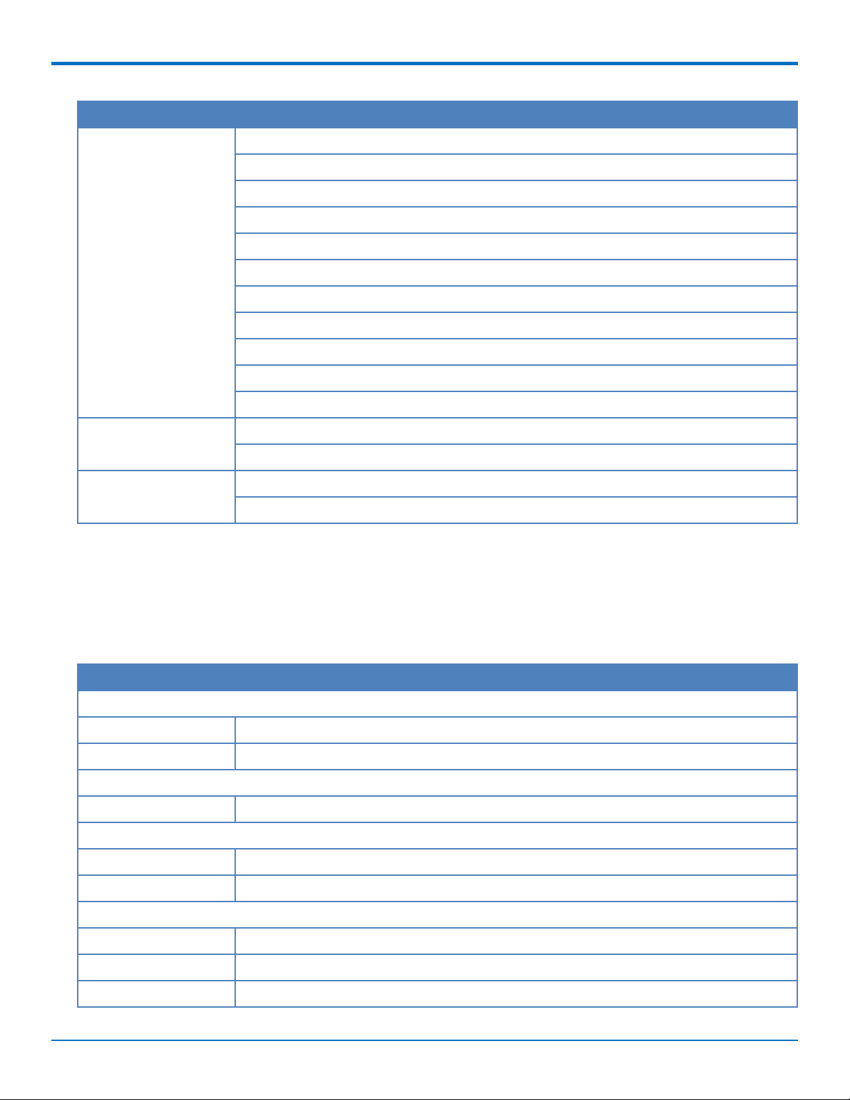
Model Options
Model Description
MTCMR-E1 Quad-band E-GPRS Class 12 performance
MTCMR-E1-GP Quad-band E-GPRS Class 12 performance; GPS
MTCMR-C1 Multi-band CDMA2000 1xRTT performance
MTCMR-C1-GP Multi-band CDMA2000 1xRTT performance; GPS
MTCMR-G2 Quad-band GSM/GPRS Class 10 performance
MTCMR-G2-GP Quad-band GSM/GPRS Class 10 performance; GPS
MTCMR-H5 Standards based tri-band UMTS/HSPA performance
MTCMR-H5-GP Standards based tri-band UMTS/HSPA performance; GPS
MTCMR-EV2 Dual-band 800/1900 MHz with receive diversity support on EVDO bands
MTCMR-EV2-GP Dual-band 800/1900 MHz with receive diversity support on EVDO bands; GPS
MTCMR-EV3 Dual-band 800/1900 MHz with receive diversity support on EVDO bands
MTCMR-EV3-GP Dual-band 800/1900 MHz with receive diversity support on EVDO bands; GPS
MTCMR-C2 CDMA Modem (RS-232/USB)
MTCMR-C2-GP CDMA Modem (RS-232/USB); GPS
Related Documentation
Use AT Commands to configure your device. The following documentation is available on the Multi-Tech website at
www.multitech.com/setup/product.go.
Model Document
All S000457 Universal IP AT Commands Reference Guide
MTCMR-H5 S000574 HSPA+ AT Commands Reference Guide
MTCMR-EV3 S000546 EV-DO and CDMA AT Commands Reference Guide
MTCMR-EV2 S000482 CDMA 1xEV-DO AT Commands Reference Guide
MTCMR-G2 S000463 GPRS G2 Modems AT Commands Reference Guide
MTCMR-E1 S000474 Wireless EDGE (E1) Modems AT Commands Reference Guide
MTCMR-C1 S000478 CDMA-C1 AT Commands Reference Guide
MTCMR-C2 S000546 EV-DO and CDMA AT Commands Reference Guide
6 MultiModem®iCell MTCMR User Guide
Page 7

PRODUCT OVERVIEW
Package Contents
Note: For HSPA+, EDGE, and GPRS devices, your wireless provider supplies the SIM card. Other models do not
use SIM cards.
Unbundled Package with No Accessories Bundled Package with Accessories
1 modem
Note: Package does not include
mounting screws, AC or DC power
supply, and antenna(s).
1 modem
1 antenna (-GP builds have an additional GPS antenna)
1 RS-232 cable
1 USB cable
1 GPIO cable
1 power supply (-GP builds do not include power supply)
Note: Package does not include mounting screws
MultiModem®iCell MTCMR User Guide 7
Page 8

SAFETY NOTICES AND WARNINGS
Chapter 2 – Safety Notices and Warnings
General Safety
The device is designed for and intended to be used in fixed and mobile applications. Fixed means the device is
physically secured at one location and cannot be easily moved to another location. Mobile means the device is
used in other than fixed locations.
CAUTION: Maintain a separation distance of at least 20 cm (8 inches) between the transmitter’s antenna and
the body of the user or nearby persons. The device is not designed for or intended to be used in portable
applications within 20 cm (8 inches) of the user’s body.
Attention: Maintenir une distance d'au moins 20 cm (8 po) entre l'antenne du récepteur et le corps de
l'utilisateur ou à proximité de personnes. Le modem n'est pas conçu pour, ou destinés à être utilisés dans les
applications portables, moins de 20 cm du corps de l'utilisateur.
Radio Frequency (RF) Safety
Due to the possibility of radio frequency (RF) interference, it is important that you follow any special regulations
regarding the use of radio equipment. Follow the safety advice given below.
Operating your device close to other electronic equipment may cause interference if the equipment is
inadequately protected. Observe any warning signs and manufacturers’ recommendations.
Different industries and businesses restrict the use of cellular devices. Respect restrictions on the use of
radio equipment in fuel depots, chemical plants, or where blasting operations are in process. Follow
restrictions for any environment where you operate the device.
Do not place the antenna outdoors.
Switch OFF your wireless device when in an aircraft. Using portable electronic devices in an aircraft may
endanger aircraft operation, disrupt the cellular network, and is illegal. Failing to observe this restriction
may lead to suspension or denial of cellular services to the offender, legal action, or both.
Switch OFF your wireless device when around gasoline or diesel-fuel pumps and before filling your vehicle
with fuel.
Switch OFF your wireless device in hospitals and any other place where medical equipment may be in use.
Sécurité relative au bâti
Lors de l'installation de l'unité dans une enceinte pouvant en héberger plusieurs, suivez la procédure d'installation
du fabricant de l'enceinte.
Note: La température ambiante à l'intérieur du bâti ne doit pas dépasser 40° Celsius.
Ne placez pas l'unité directement sur le dessus ou en dessous d'un autre équipement.
Si l'unité est installée dans une enceinte pouvant en héberger plusieurs, veillez à ce que l'air circule
correctement dans le bâti afin que la température ambiante maximale recommandée (40° C) ne soit pas
dépassée.
Veillez à ce que l'unité soit correctement mise à la terre en vérifiant la fiabilité du raccordement de terre
lorsque l'unité est installée dans un bâti.
Si une multiprise est utilisée, veillez à ce qu'elle fournisse une mise à la terre appropriée à l'appareil qui y
est branché.
8 MultiModem®iCell MTCMR User Guide
Page 9

SAFETY NOTICES AND WARNINGS
Lors de l'installation de l'équipement dans un bâti, veillez à ce que la charge mécanique soit homogène de
sorte à éviter toute situation potentiellement dangereuse. Le bâti doit supporter le poids de l'ensemble des
équipements qu'il contient.
Assurez-vous que le circuit d'alimentation principale est capable de gérer la charge de l' équipement.
Consultez l'étiquette d'alimentation sur l'équipement pour connaître les spécifications relatives aux charges.
Cet équipement ne doit être installé que par un technicien de maintenance dûment qualifié. Ne raccordez
des circuits que s'ils sont du même type: raccordez un circuit STBT (Secondaire Très Basse Tension) à un
autre circuit STBT et un circuit RT (Réseau de télécommunications) à un autre circuit RT.
Interference with Pacemakers and Other Medical Devices
Potential interference
Radio frequency energy (RF) from cellular devices can interact with some electronic devices. This is
electromagnetic interference (EMI). The FDA helped develop a detailed test method to measure EMI of implanted
cardiac pacemakers and defibrillators from cellular devices. This test method is part of the Association for the
Advancement of Medical Instrumentation (AAMI) standard. This standard allows manufacturers to ensure that
cardiac pacemakers and defibrillators are safe from cellular device EMI.
The FDA continues to monitor cellular devices for interactions with other medical devices. If harmful interference
occurs, the FDA will assess the interference and work to resolve the problem.
Precautions for pacemaker wearers
If EMI occurs, it could affect a pacemaker in one of three ways:
Stop the pacemaker from delivering the stimulating pulses that regulate the heart's rhythm.
Cause the pacemaker to deliver the pulses irregularly.
Cause the pacemaker to ignore the heart's own rhythm and deliver pulses at a fixed rate.
Based on current research, cellular devices do not pose a significant health problem for most pacemaker wearers.
However, people with pacemakers may want to take simple precautions to be sure that their device doesn't cause
a problem.
Keep the device on the opposite side of the body from the pacemaker to add extra distance between the
pacemaker and the device.
Avoid placing a turned-on device next to the pacemaker (for example, don’t carry the device in a shirt or
jacket pocket directly over the pacemaker).
Vehicle Safety
When using your device in a vehicle:
Do not use this device while driving.
Respect national regulations on the use of cellular devices in vehicles.
If incorrectly installed in a vehicle, operating the wireless device could interfere with the vehicle’s
electronics. To avoid such problems, use qualified personnel to install the device. The installer should verify
the vehicle electronics are protected from interference.
Using an alert device to operate a vehicle’s lights or horn is not permitted on public roads.
MultiModem®iCell MTCMR User Guide 9
Page 10

SAFETY NOTICES AND WARNINGS
UL evaluated this device for use in ordinary locations only. UL did NOT evaluate this device for installation in
a vehicle or other outdoor locations. UL Certification does not apply or extend to use in vehicles or outdoor
applications.
User Responsibility
Respect all local regulations for operating your wireless device. Use the security features to block unauthorized use
and theft.
Device Maintenance
Do not attempt to disassemble the device. There are no user serviceable parts inside.
When maintaining your device:
Do not misuse the device. Follow instructions on proper operation and only use as intended. Misuse could
make the device inoperable, damage the device and/or other equipment, or harm users.
Do not apply excessive pressure or place unnecessary weight on the device. This could result in damage to
the device or harm to users.
Do not use this device in explosive or hazardous environments unless the model is specifically approved for
such use. The device may cause sparks. Sparks in explosive areas could cause explosion or fire and may
result in property damage, severe injury, and/or death.
Do not expose your device to any extreme environment where the temperature or humidity is high. Such
exposure could result in damage to the device or fire. Refer to the device specifications regarding
recommended operating temperature and humidity.
Do not expose the device to water, rain, or spilled beverages. Unless the device is IP67 rated, it is not
waterproof. Exposure to liquids could result in damage to the device.
Do not place the device alongside computer discs, credit or travel cards, or other magnetic media. The
information contained on discs or cards may be affected by the device.
Using accessories, such as antennas, that MultiTech has not authorized or that are not compliant with
MultiTech's accessory specifications may invalidate the warranty.
If the device is not working properly, contact MultiTech Technical Support.
10 MultiModem®iCell MTCMR User Guide
Page 11
LEDS, CONNECTORS, AND SPECIFICATIONS
Chapter 3 – LEDs, Connectors, and Specifications
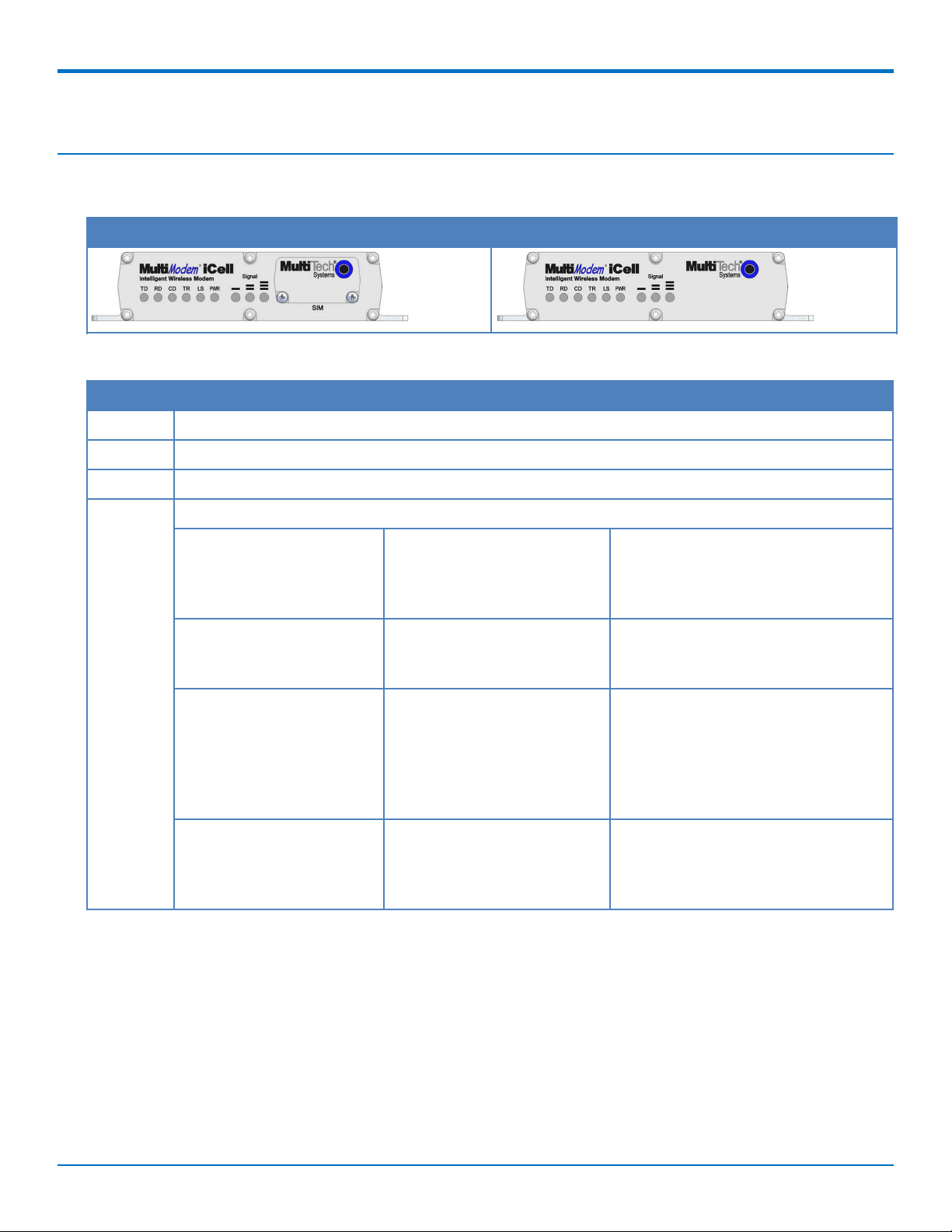
Front
MTCMR-E1, -G2, -H5 MTCMR-C1, -C2, -EV2, -EV3
LEDs
LED Description
TD Transmit Data: Lights when device transmits data. Not valid while in USB mode.
RD Receive Data: Lights when device receives data. Not valid while in USB mode.
CD Carrier Detect: Lights when there is a data connection. Not valid while in USB mode.
LS Link Status: LED behavior depends on model.
H5, C2, EV3, and EV2
models
Continuous ON indicates
device is powered on and
registered on the network.
Slow flashing (5 seconds)
indicates device is on and
searching for a network.
Fast flashing (0.3 seconds)
indicates device is
transmitting or receiving.
G2 and C1 models E1 model
Continuous ON indicates
device is not registered on the
network.
Flashing at 200 ms on / 2 sec
indicates registration on
network.
Flashing at 200 ms on / 600
ms off indicates it is registered
on a network and
communication is in progress.
Note: Set AT^SSYNC to 1 for
the following default LED
timings:
Continuous ON indicates connected to
remote party (CSD call).
Flashing at 600 ms on/600 ms off is
limited network service: No SIM card
inserted or no PIN entered, or network
search in progress or ongoing user
authentication, or network login in
progress.
Flashing at 75 ms on/3 sec off is idle
mode: Registered to the GSM network
(monitoring control channels and user
interactions). No call is in progress.
MultiModem®iCell MTCMR User Guide 11
Page 12
LEDS, CONNECTORS, AND SPECIFICATIONS
LED Description
OFF indicates device is
turned off or not powered.
TR Terminal Ready: Indicates a readiness signal from the PC.
PWR/GPS Power: Lights device has DC power.
GPS: If device has valid GPS signal, LED blinks at 1 second ON and 0.5 second OFF. If invalid GPS
signal, LED is solid.
Signal ALL OFF – Unit is off, not registered on a network or has an extremely weak signal (0 < =
RSSI < 6).
1 Bar ON – Very weak signal (7 < = RSSI < 14)
1 and 2 Bars ON – Weak signal (15 < = RSSI < 23)
1, 2, and 3 Bars ON – Good signal (24 < = RSSI < 31)
OFF indicates device is turned
off or in download mode.
Flashing at 75 ms on/ 75 ms off/75
ms on/3 sec off indicates one or more
GPRS contexts activated.
Flashing at 500 ms on/ 25 ms off
indicates packet switched data
transfer in progress.
OFF indicates ME is in one of the
following modes: power down mode,
airplane mode, non-cyclic sleep mode
with no temporary wake-up event in
progress.
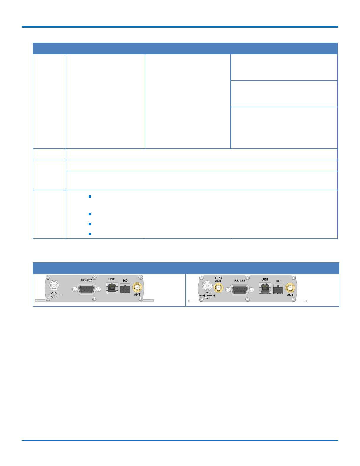
Back
MTCMR No GPS MTCMR with GPS
12 MultiModem®iCell MTCMR User Guide
Page 13

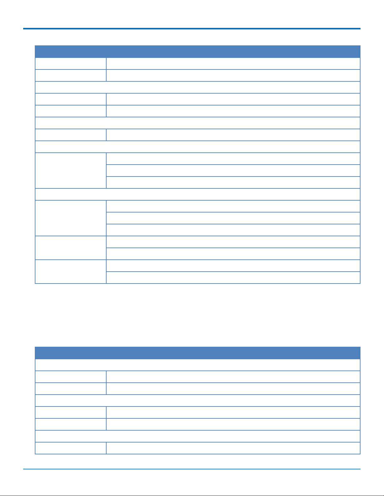
MTCMR-H5 Specifications
Category Description
General
Performance HSPA+
Frequency Bands Penta band 850/900/1700/1900/2100 MHz
Speed
Packet Data HSDPA data service of up to 21.0 Mbps
HSUPA data service of up to 5.76 Mbps
Physical Description
Weight 0.45 lbs. (200 g)
Dimensions 3.1 in x 4.9 in x 1.1 in (7.9 cm x 12.4 cm x 2.8 cm)
Connectors
Cellular 50 ohm SMA (female connector)
LEDS, CONNECTORS, AND SPECIFICATIONS
RS-232 DE9
GPIO 6 pin 2x3 style
Power 2.5mm miniature (screw-on)
USB Type B
SIM Holder Standard 1.8V and 3V
Environment
Operating Temperature -22° to 158° F (-30° to 70° C)
Humidity 20%-90% relative humidity, non-condensing
Power Requirements
Voltage 9V to 32V DC
SMS
SMS Point-to-Point messaging
Text and PDU
Cell broadcast
Certifications and Compliance
EMC Compliance FCC Part 15 Class B
1
EN55022 Class B
MultiModem®iCell MTCMR User Guide 13
Page 14
LEDS, CONNECTORS, AND SPECIFICATIONS
Category Description
Radio Compliance FCC Part 22
FCC Part 24
RSS 132
RSS 133
EN 301 511
EN 301 489-1
EN 301 489-3 (GPS models only)
EN 301 489-7
EN 301 489-24
EN 301 908
AS/ACIF S042.1, S042.3
Safety Compliance UL/cUL 60950-1 2nd Ed
IEC60950-1 2nd Ed am.1
Network Compliance PTCRB
AT&T
1
UL Listed at 40° C, limited by power supply. UL Certification does not apply or extend to an ambient above 40° C
and has not been evaluated by UL for ambient greater than 40° C. “UL has evaluated this device for use in ordinary
locations only. Installation in a vehicle or other outdoor locations has not been evaluated by UL. UL Certification
does not apply or extend to use in vehicles or outdoor applications or in ambient above 40° C.”
MTCMR-EV3 Specifications
Category Description
General
Performance EV-DO Rev A
Frequency Bands Dual band 900/1800 MHz
Speed
Packet Data Up to 3.1M downlink and 5.76M bps uplink
Physical Description
Weight 0.45 lbs. (200 g)
Dimensions 3.1 in x 4.9 in x 1.1 in (7.9 cm x 12.4 cm x 2.8 cm)
Connectors
Cellular 50 ohm SMA (female connector)
RS-232 DE9
GPIO 6 pin 2x3 style
14 MultiModem®iCell MTCMR User Guide
Page 15
Category Description
Power 2.5mm miniature (screw-on)
USB Type B
Environment
Operating Temperature -22° to 185° F (-30° to 85° C)
1
Humidity 20%-90% relative humidity, non-condensing
Power Requirements
Voltage 9V to 32V DC
SMS
SMS Point-to-Point messaging
Text and PDU
Cell broadcast
Certifications and Compliance
LEDS, CONNECTORS, AND SPECIFICATIONS
EMC Compliance FCC Part 15 Class B
EN55022 Class B
EN55024
Radio Compliance FCC Part 22
FCC Part 24
Safety Compliance UL/cUL 60950-1 2nd Ed
IEC60950-1 2nd Ed am.1
1
UL Listed at 40° C, limited by power supply. UL Certification does not apply or extend to an ambient above 40° C
and has not been evaluated by UL for ambient greater than 40° C. “UL has evaluated this device for use in ordinary
locations only. Installation in a vehicle or other outdoor locations has not been evaluated by UL. UL Certification
does not apply or extend to use in vehicles or outdoor applications or in ambient above 40° C.”
MTCMR-EV2 Specifications
Category Description
General
Performance EV-DO Rev A backwards compatible to EV-DO Rev 0 and CDMA2000 1xRTT
Frequency Bands Dual band 800/1900 MHz
Speed
Packet Data Up to 3.1 Kbps download and 1.8 Kbps upload.
Circuit Switched Data IS-95A, IS-95B up to 14.4K bps
Physical Description
Weight 0.45 lbs. (200 g)
MultiModem®iCell MTCMR User Guide 15
Page 16

LEDS, CONNECTORS, AND SPECIFICATIONS
Category Description
Dimensions 3.1 in x 4.9 in x 1.1 in (7.9 cm x 12.4 cm x 2.8 cm)
Connectors
Cellular 50 ohm SMA (female connector)
RS-232 DE9
GPIO 6 pin 2x3 style
Power 2.5mm miniature (screw-on)
USB Type B
Environment
Operating Temperature -22° to 185° F (-30° to 85° C)
1
Humidity 20%-90% relative humidity, non-condensing
Power Requirements
Voltage 9V to 32V DC
SMS, Wi-Fi, Bluetooth
SMS Point-to-Point messaging
Text and PDU
Certifications and Compliance
EMC Compliance FCC Part 15 Class B
EN55022 Class B
Radio Compliance FCC Part 22
FCC Part 24
Safety Compliance UL 60950-1 2nd Ed
IEC60950-1 2nd Ed am.1
1
UL Listed at 40° C, limited by power supply. UL Certification does not apply or extend to an ambient above 40° C
and has not been evaluated by UL for ambient greater than 40° C. “UL has evaluated this device for use in ordinary
locations only. Installation in a vehicle or other outdoor locations has not been evaluated by UL. UL Certification
does not apply or extend to use in vehicles or outdoor applications or in ambient above 40° C.”
16 MultiModem®iCell MTCMR User Guide
Page 17

LEDS, CONNECTORS, AND SPECIFICATIONS
MTCMR-G2 Specifications
Category Description
General
Performance GPRS: Class 10
Frequency Bands Quad-band GSM/GPRS/EDGE: 850/900/1800/1900 MHz
Speed
Packet Data Up to 85.6K bps, coding schemes CS1 to CS4
Circuit Switched Data Up to 14.4 Kbps transparent and non-transparent
Physical Description
Weight 0.45 lbs. (200 g)
Dimensions 3.1 in x 4.9 in x 1.1 in (7.9 cm x 12.4 cm x 2.8 cm)
Connectors
Cellular 50 ohm SMA (female connector)
RS-232 DE9
GPIO 6 pin 2x3 style
Power 2.5mm miniature (screw-on)
USB Type B
SIM Holder Standard 1.8V and 3V
Environment
Operating Temperature -40° to 185° F (-40° to 85° C)
Humidity 20%-90% relative humidity, non-condensing
Power Requirements
Voltage 9V to 32V DC
SMS, Wi-Fi, Bluetooth
SMS Point-to-Point messaging
Text and PDU
Cell broadcast
Certifications and Compliance
EMC Compliance FCC Part 15 Class B
1
EN55022 Class B
MultiModem®iCell MTCMR User Guide 17
Page 18

LEDS, CONNECTORS, AND SPECIFICATIONS
Category Description
Radio Compliance FCC Part 22
FCC Part 24
RSS 132
RSS 133
EN 301 511
EN 301 489-1
EN 301 489-3 (GPS models only)
EN 301 489-7
EN 301 908
AS/ACIF S042.1, S042.3
Safety Compliance UL/cUL 60950-1 2nd Ed
IEC60950-1 2nd Ed am.1
Network Compliance PTCRB
AT&T
1
UL Listed at 40° C, limited by power supply. UL Certification does not apply or extend to an ambient above 40° C
and has not been evaluated by UL for ambient greater than 40° C. “UL has evaluated this device for use in ordinary
locations only. Installation in a vehicle or other outdoor locations has not been evaluated by UL. UL Certification
does not apply or extend to use in vehicles or outdoor applications or in ambient above 40° C.”
MTCMR-C1 Specifications
Category Description
General
Performance CDMA2000 1xRTT
Frequency Bands Dual band 800/1900 MHz
Speed
Packet Data Up to 153.6K bps forward and reverse
Circuit Switched Data IS-95A, IS-95B up to 14.4K bps forward and reverse
Physical Description
Weight 0.45 lbs. (200 g)
Dimensions 3.1 in x 4.9 in x 1.1 in (7.9 cm x 12.4 cm x 2.8 cm)
Connectors
Cellular 50 ohm SMA (female connector)
RS-232 DE9
GPIO 6 pin 2x3 style
18 MultiModem®iCell MTCMR User Guide
Page 19

Category Description
Power 2.5mm miniature (screw-on)
USB Type B
Environment
Operating Temperature -40° to 185° F (-40° to 85° C)
1
Humidity 20%-90% relative humidity, non-condensing
Power Requirements
Voltage 9V to 32V DC
SMS
SMS Point-to-Point messaging
Text and PDU
Cell broadcast
Certifications and Compliance
LEDS, CONNECTORS, AND SPECIFICATIONS
EMC Compliance FCC Part 15 Class B
EN55022 Class B
Radio Compliance FCC Part 22
FCC Part 24
RSS 132
RSS 133
Safety Compliance UL/cUL 60950-1 2nd Ed
IEC60950-1 2nd Ed am.1
1
UL Listed at 40° C, limited by power supply. UL Certification does not apply or extend to an ambient above 40° C
and has not been evaluated by UL for ambient greater than 40° C. “UL has evaluated this device for use in ordinary
locations only. Installation in a vehicle or other outdoor locations has not been evaluated by UL. UL Certification
does not apply or extend to use in vehicles or outdoor applications or in ambient above 40° C.”
MTCMR-C2 Specifications
Category Description
General
Performance 2G CDMA 1xRTT
Frequency Bands Dual-band 800/1900 MHz CDMA
Speed
Packet Data Peak downlink speeds up to 153 Kbps Peak uplink speeds up to 153 Kbps
Physical Description
Weight 0.45 lbs. (200 g)
MultiModem®iCell MTCMR User Guide 19
Page 20

LEDS, CONNECTORS, AND SPECIFICATIONS
Category Description
Dimensions 3.1 in x 4.9 in x 1.1 in (7.9 cm x 12.4 cm x 2.8 cm)
Connectors
Cellular 50 ohm SMA (female connector)
RS-232 DE9
GPIO 6 pin 2x3 style
Power 2.5mm miniature (screw-on)
USB Type B
Environment
Operating Temperature -22° to 185° F (-30° to 85° C)
1
Humidity 20%-90% relative humidity, non-condensing
Power Requirements
Voltage 9V to 32V DC
SMS
SMS Point-to-Point messaging
Text and PDU
Certifications and Compliance
EMC Compliance FCC Part 15 Class B
EN55022 Class B
Radio Compliance FCC Part 22
FCC Part 24
Safety Compliance UL/cUL 60950-1 2nd Ed
IEC60950-1 2nd Ed am.1
1
UL Listed at 40° C, limited by power supply. UL Certification does not apply or extend to an ambient above 40° C
and has not been evaluated by UL for ambient greater than 40° C. “UL has evaluated this device for use in ordinary
locations only. Installation in a vehicle or other outdoor locations has not been evaluated by UL. UL Certification
does not apply or extend to use in vehicles or outdoor applications or in ambient above 40° C.”
MTCMR-E1 Specifications
Category Description
General
Performance EDGE: E-GPRS Class 12
GPRS: Class 10
Frequency Bands Quad-band GSM/GPRS/EDGE: 850/900/1800/1900 MHz
Speed
20 MultiModem®iCell MTCMR User Guide
Page 21

LEDS, CONNECTORS, AND SPECIFICATIONS
Category Description
Packet Data EDGE: E-GPRS Up to 240K bps, coding scheme MCS 1-9, mobile station Class B, LLC layer,
4 time slots.
GPRS: Full PBCCH support, coding scheme 1-4, mobile station Class B
Circuit Switched Data Up to 14.4K bps, non-transparent
Physical Description
Weight 0.45 lbs. (200 g)
Dimensions 3.1 in x 4.9 in x 1.1 in (7.9 cm x 12.4 cm x 2.8 cm)
Connectors
Cellular 50 ohm SMA (female connector)
RS-232 DE9
GPIO 6 pin 2x3 style
Power 2.5mm miniature (screw-on)
USB Type B
SIM Holder Standard 1.8V and 3V
Environment
Operating Temperature -22° to 158° F (-30° to 70° C)
1
Humidity 20%-90% relative humidity, non-condensing
Power Requirements
Voltage 9V to 32V DC
SMS, Wi-Fi, Bluetooth
SMS Point-to-Point messaging
Text and PDU
Cell broadcast
Certifications and Compliance
EMC Compliance EN55022 Class B
MultiModem®iCell MTCMR User Guide 21
Page 22

LEDS, CONNECTORS, AND SPECIFICATIONS
Category Description
Radio Compliance FCC Part 22
FCC Part 24
RSS 132
RSS 133
EN 301 511
EN 301 489-1
EN 301 489-3 (GPS models only)
EN 301 489-7
EN 301 908
AS/ACIF S042.1, S042.3
Safety Compliance UL/cUL 60950-1 2nd Ed
IEC60950-1 2nd Ed am.1
Network Compliance PTCRB
AT&T
1
UL Listed at 40° C, limited by power supply. UL Certification does not apply or extend to an ambient above 40° C
and has not been evaluated by UL for ambient greater than 40° C. “UL has evaluated this device for use in ordinary
locations only. Installation in a vehicle or other outdoor locations has not been evaluated by UL. UL Certification
does not apply or extend to use in vehicles or outdoor applications or in ambient above 40° C.”
22 MultiModem®iCell MTCMR User Guide
Page 23

LEDS, CONNECTORS, AND SPECIFICATIONS
Power Measurements
Multi-Tech Systems, Inc. recommends that you incorporate a 10% buffer into your power source when determining
product load.
Note: Note the following:
Maximum: The continuous current during maximum data rate with the radio transmitter at
maximum power.
Peak: The peak current during a transmission burst period.
In-rush Current: The input current during power up, or a reset.
MTCMR-H5
GSM 850
Idle Typical Maximum Peak TX In-rush Current
9 volts
Current (AMPS) 0.057 0.080 0.185 1.18 1.61
Watts 0.526 0.740 1.700
20 volts
Current (AMPS) 0.030 0.044 0.087 0.530 1.71
Watts 0.600 0.880 1.740
32 volts
Current (AMPS) 0.021 0.031 0.054 0.332 1.46
Watts 0.672 0.992 1.73
HSPA+
Idle Typical Maximum Peak TX In-rush Current
9 volts
Current (AMPS) 0.057 0.140 0.270 0.340 1.61
Watts 0.526 1.290 2.47
20 volts
Current (AMPS) 0.030 0.070 0.131 0.196 1.71
Watts 0.600 1.400 2.62
32 volts
Current (AMPS) 0.021 0.048 0.086 0.152 1.46
Watts 0.672 1.54 2.75
MultiModem®iCell MTCMR User Guide 23
Page 24

LEDS, CONNECTORS, AND SPECIFICATIONS
MTCMR-H5-GP
GSM 850
Idle Typical Maximum Peak TX In-rush Current
9 volts
Current (AMPS) 0.097 0.125 0.225 1.32 1.63
Watts 0.895 1.150 2.070
20 volts
Current (AMPS) 0.051 0.063 0.108 0.570 1.74
Watts 1.020 1.260 2.160
32 volts
Current (AMPS) 0.035 0.043 0.072 0.340 1.47
Watts 1.120 1.380 2.300
HSPA+
Idle Typical Maximum Peak TX In-rush Current
9 volts
Current (AMPS) 0.096 0.182 0.310 0.384 1.63
Watts 0.890 1.670 2.840
20 volts
Current (AMPS) 0.051 0.092 0.153 0.220 1.74
Watts 1.020 1.840 3.060
32 volts
Current (AMPS) 0.035 0.062 0.100 0.164 1.47
Watts 1.120 1.980 3.200
MTCMR-EV3
CDMA 2000
Typical Maximum Peak TX In-rush Current
9 volts
Current (AMPS) 0.121 0.330 0.404 2.55
Watts 1.09 2.97
20 volts
Current (AMPS) 0.061 0.155 0.228 1.89
Watts 1.22 3.10
32 volts
24 MultiModem®iCell MTCMR User Guide
Page 25

LEDS, CONNECTORS, AND SPECIFICATIONS
Typical Maximum Peak TX In-rush Current
Current (AMPS) 0.045 0.107 0.176 1.70
Watts 1.44 3.42
EV-DO
Typical Maximum Peak TX In-rush Current
9 volts
Current (AMPS) 0.118 0.275 0.360 2.55
Watts 1.06 2.48
20 volts
Current (AMPS) 0.061 0.133 0.204 1.89
Watts 1.22 2.66
32 volts
Current (AMPS) 0.043 0.091 0.156 1.70
Watts 1.38 2.91
MTCMR-EV3-GP
CDMA 2000
Typical Maximum Peak TX In-rush Current
9 volts
Current (AMPS) 0.160 0.354 0.430 2.42
Watts 1.44 3.19
20 volts
Current (AMPS) 0.086 0.173 0.24 1.86
Watts 1.72 3.46
32 volts
Current (AMPS) 0.049 0.110 0.18 1.65
Watts 1.57 3.52
EV-DO
Typical Maximum Peak TX In-rush Current
9 volts
Current (AMPS) 0.168 0.330 0.412 2.42
Watts 1.51 2.97
20 volts
MultiModem®iCell MTCMR User Guide 25
Page 26

LEDS, CONNECTORS, AND SPECIFICATIONS
Typical Maximum Peak TX In-rush Current
Current (AMPS) 0.084 0.158 0.232 1.86
Watts 1.68 3.16
32 volts
Current (AMPS) 0.056 0.105 0.176 1.65
Watts 1.79 3.36
MTCMR-EV2
CDMA 2000
Sleep Typical Maximum
9 volts
Current (AMPS) 0.061 0.160 0.485
Watts 0.56 1.47 4.41
20 volts
Current (AMPS) 0.030 0.081 0.230
Watts 0.60 1.62 4.60
32 volts
Current (AMPS) 0.023 0.055 0.152
Watts 0.74 1.76 4.86
EV-DO
Sleep Typical Maximum
9 volts
Current (AMPS) 0.108 0.330 0.580
Watts 1.00 3.04 5.27
20 volts
Current (AMPS) 0.052 0.165 0.313
Watts 1.04 3.30 6.26
32 volts
Current (AMPS) 0.041 0.105 0.205
Watts 1.31 3.36 6.56
26 MultiModem®iCell MTCMR User Guide
Page 27

MTCMR-EV2
CDMA 2000
Sleep Typical Maximum
9 volts
Current (AMPS) 0.119 0.220 0.560
Watts 1.10 2.02 5.09
20 volts
Current (AMPS) 0.062 0.110 0.265
Watts 1.24 2.20 5.30
32 volts
Current (AMPS) 0.044 0.075 0.175
Watts 1.141 2.40 5.60
EV-DO
LEDS, CONNECTORS, AND SPECIFICATIONS
Sleep Typical Maximum
9 volts
Current (AMPS) 0.167 0.370 0.625
Watts 1.54 3.40 5.68
20 volts
Current (AMPS) 0.087 0.192 0.345
Watts 1.74 3.84 6.90
32 volts
Current (AMPS) 0.062 0.121 0.225
Watts 1.198 3.87 7.20
MultiModem®iCell MTCMR User Guide 27
Page 28

LEDS, CONNECTORS, AND SPECIFICATIONS
MTCMR-G2
Sleep Typical Maximum Peak TX
9 volts
Current (AMPS) 0.069 0.109 0.194 1.53
Watts 0.640 1.010 1.790
20 volts
Current (AMPS) 0.038 0.056 0.096 0.668
Watts 0.760 1.120 1.920
32 volts
Current (AMPS) 0.030 0.041 0.065 0.453
Watts 0.960 1.300 2.100
MTCMR-G2-GP
Sleep Typical Maximum Peak TX
9 volts
Current (AMPS) 0.083 0.130 0.233 1.83
Watts 0.770 1.190 2.130
20 volts
Current (AMPS) 0.046 0.067 0.115 0.801
Watts 0.920 1.340 2.300
32 volts
Current (AMPS) 0.036 0.050 0.078 0.543
Watts 1.150 1.600 2.500
MTCMR-C1
Sleep Typical Maximum
9 volts
Current (AMPS) 0.048 0.128 0.360
Watts 0.44 1.18 3.31
20 volts
Current (AMPS) 0.027 0.065 0.171
Watts 0.54 1.30 3.42
32 volts
Current (AMPS) 0.021 0.046 0.115
28 MultiModem®iCell MTCMR User Guide
Page 29

Sleep Typical Maximum
Watts 0.67 1.47 3.68
MTCMR-C1-GP
Sleep Typical Maximum
9 volts
Current (AMPS) 0.096 0.175 0.435
Watts 0.89 1.62 4.00
20 volts
Current (AMPS) 0.052 0.092 0.205
Watts 1.04 1.84 4.10
32 volts
Current (AMPS) 0.037 0.062 0.135
Watts 1.18 1.98 4.32
LEDS, CONNECTORS, AND SPECIFICATIONS
MTCMR-C2
9 volts
PCS (1900 MHz) Curren
t
(AMPS)
Watts 0.73 1.09 3.03
20 volts
PCS (1900 MHz) Curren
t
(AMPS)
Watts 0.0.84 1.10 3.06
32 volts
PCS (1900 MH) Curren
t
(AMPS)
Watts 0.93 1.63 4.38
Idle Typical Maximum Peak Inrush
0.079 0.118 0.424 0.463 2.09
0.042 0.054 0.195 0.239 1.81
0.029 0.051 0.137 0.176 1.35
MultiModem®iCell MTCMR User Guide 29
Page 30

LEDS, CONNECTORS, AND SPECIFICATIONS
MTCMR-C2-GP
9 volts
Idle Typical Maximum Peak Inrush
Curren
t
PCS (1900 MHz) Curren
t
(AMPS)
Watts 1.10 1.46 4.10
20 volts
PCS (1900 MHz) Curren
t
(AMPS)
Watts 1.22 1.58 4.26
32 volts
PCS (1900 MH) Curren
t
(AMPS)
Watts 1.38 1.76 4.48
MTCMR-E1
Sleep Typical Maximum Peak TX
9 volts
0.119 0.158 0.448 0.488 2.09
0.061 0.079 0.213 0.252 1.81
0.043 0.055 0.140 0.18 1.35
Current (AMPS) 0.091 0.149 0.416 2.5
Watts 0.84 1.37 3.77
20 volts
Current (AMPS) 0.048 0.077 0.190 0.895
Watts 0.96 1.54 3.80
32 volts
Current (AMPS) 0.034 0.054 0.124 0.625
Watts 1.088 1.73 3.97
MTCMR-E1-GP
Sleep Typical Maximum Peak TX
9 volts
Current (AMPS) 0.098 0.160 0.410 2.25
Watts 0.91 1.48 3.77
30 MultiModem®iCell MTCMR User Guide
Page 31

LEDS, CONNECTORS, AND SPECIFICATIONS
Sleep Typical Maximum Peak TX
20 volts
Current (AMPS) 0.051 0.080 0.190 0.890
Watts 1.02 1.60 3.80
32 volts
Current (AMPS) 0.035 0.056 0.122 0.609
Watts 1.125 1.79 3.90
Powering Down Your Device (C2, H5, EV3)
CAUTION: Failing to properly shutdown the device before removing power may corrupt your device's file system.
For the C2, H5 and EV3 only, to properly power down your device, use the following sequence:
1. Issue the AT#SHDN command.
2. Wait 30 seconds.
3. Power off the device. Disconnect power from the device.
RF Specifications
GSM 850 EGSM 900 GSM 1800 GSM 1900 CDMA 800 CDMA 1900
Frequency RX 869 to 894
MHz
Frequency TX 824 to 849
MHz
RF Power Stand 2W at 12.5%
duty cycle
925 to 960
MHz
880 to 915
MHz
2W at 12.5%
duty cycle
1805 to 1800
MHz
1710 to 1785
MHz
1W at 12.5%
duty cycle
1930 to 1990
MHz
1850 to 1910
MHz
1W at 12.5%
duty cycle
869 to 894
MHz
824 to 849
MHz
-- --
1930 to 1990
MHz
1850 to 1910
MHz
Antenna Information
PTCRB Requirements
There cannot be any alteration to the authorized antenna system. The antenna system must be the same type with
similar in-band and out-of-band radiation patterns and maintain the same specifications.
HEPTA Antenna Information
Authorized Antenna/Antenna Specifications for Cellular Bands
The cellular radio portion of the device is approved with the following antenna or for alternate antennas meeting
the given specifications.
Manufacturer: Laird Technologies.
Description: HEPTA-SM
Model Number: MAF94300
MultiModem®iCell MTCMR User Guide 31
Page 32

LEDS, CONNECTORS, AND SPECIFICATIONS
Multi-Tech Part Number: 45009735L
MultiTech Ordering Information:
Model Quantity
ANHB-1HRA 1
ANHB-10HRA 10
ANHB-50HRA 50
3G Antenna Requirements/Specifications
Category Description
Frequency Range 824 – 960 MHz / 1710 – 1990 MHz / 1920 – 2170 MHz
Impedance 50 Ohms
VSWR VSWR should not exceed 2.0:1 at any point across the bands of operation
Typical Radiated Gain 850 MHz 3.17 dBi
950 MHz 3.51 dBi
1800 MHz 3.55 dBi
1900 MHz 3.0 dBi
2100 MHz 3.93 dBi
Radiation Omni-directional
Polarization Linear Vertical
EV-DO and CDMA Antenna Information
EV-DO and CDMA Authorized Antennas
These devices were approved with the following antenna:
Manufacturer: Exceltek Electronics Ltd.
Manufacturer's Model Number: C0081-ANG0002
MultiTech Part Number 45009713L
Multi-Tech ordering information:
Model Quantity
ANQB-1HRA 1
ANQB-10HRA 10
ANQB-50HRA 50
32 MultiModem®iCell MTCMR User Guide
Page 33

LEDS, CONNECTORS, AND SPECIFICATIONS
EV-DO and CDMA Antenna Requirements
Category Description
Frequency Range 824 - 894 MHz / 1850 - 1990 MHz
Impedance 50 Ohms
VSWR VSWR should not exceed 2.0:1 at any point across the bands of operation
Typical Radiated Gain 2 dBi on azimuth plane
Radiation Omni-directional
Polarization Linear vertical
GSM/EGSM Antenna Requirements/Specifications
Category Description
Frequency Range 824—960 MHz / 1710—1990 MHz
Impedance 50 Ohms
VSWR VSWR should not exceed 2.0:1 at any point across the bands of operation
Typical Radiated Gain 3 dBi on azimuth plane
Radiation Omni-directional
Polarization Linear Vertical
Wave Half Wave Dipole
FCC Requirements Note
FCC Requirements Note The antenna gain, including cable loss, for the radio you are incorporating into your
product design must not exceed the requirements at 850 MHz and 1900 MHz as specified by the FCC grant for
mobile operations and fixed mounted operations as defined in 2.1091 and 1.1307 of the FCC rules for satisfying RF
exposure compliance. The antenna used for transmitting must be installed to provide a separation distance of at
least 20 cm from all persons and must not transmit simultaneously with any other antenna transmitters. User and
installers must be provided with antenna installation instructions and transmitter operating conditions to satisfying
RF exposure compliance.
Global Positioning System (GPS)
This information applies only to the models with the GPS option.
Category Description
Receiver Type L1 Frequency
GPS C/A code
SBAS Capable
51 Channel Acquisitions
14 Channel Tracking
Sensitivity Tracking -161dBm
MultiModem®iCell MTCMR User Guide 33
Page 34

LEDS, CONNECTORS, AND SPECIFICATIONS
Category Description
Accuracy Position 2.5m CEP
Velocity 0.1m/sec
Update Rate 1Hz standard
Dynamics 4G
Open Sky TTFF Hot start 1 second
Cold start 29 seconds average
Reacquisition < 1s
Operational Limits Altitude < 18,000m or Velocity < 515m/s
Datum Default WGS-84
Interface UART
Protocol NMEA-0183 V3.01, GGA, GLL, GSA, GSV, RMC, VTG
Underwriters Laboratories, Inc. Required Global Positioning System (GPS) Statement
Note the following information required by Underwriters Laboratories: Underwriters Laboratories, Inc.
Underwriters Laboratories Inc.(“UL”) has not tested the performance or reliability of the Global Positioning System
(“GPS”) hardware, operating software or other aspects of this product. UL has only tested for fire, shock or
casualties as outlined in UL ’s Standard(s) for Safety. UL60950-1 Certification does not cover the performance or
reliability of the GPS hardware and GPS operating software. UL MAKES NO REPRESENTATIONS, WARRANTIES OR
CERTIFICATIONS WHATSOEVER REGARDING THE PERFORMANCE OR RELIABILITY OF ANY GPS RELATED FUNCTIONS
OF THIS PRODUCT.
Connecting Direct DC Power accessories
To connect direct DC power in a vehicle:
Note: The device has over-voltage protection. To ensure complete protection, you can add additional filtering
to the DC input.
Note: For automotive applications you can use permanent “+” or keyswitched “+” source.
1. Connect the DC power cable to the power connector on the modem.
2. Attach the two wires at the DC power cable's other end to a DC fuse/terminal block where you are
mounting the device.
3. Connect red wire to the "+" (positive) terminal and black wire to the "–" (negative) terminal.
4. Verify the ground connection is correct.
34 MultiModem®iCell MTCMR User Guide
Page 35

GPIO
GPIO Cable
LEDS, CONNECTORS, AND SPECIFICATIONS
GPIO Connector
Use Universal IP (UIP) AT Commands to configure GPIO pins. Refer to the Universal IP (UIP) AT Command
Reference Guide for more information.
Pin Number Description GPIO 6-pin Connector
Pin 1 DIO 0
Pin 2 DIO 1
Pin 3 DIO 2/ADC 0
Pin 4 DIO 3/ADC 1
Pin 5 ADC2
Pin 6 Gnd
You can program GPIO pins independently.
Pin 1 Digital Input, 24 Volt tolerant. The circuit consists of an opto-coupler with a 3.01K resistor in series
with the diode.
Pin 2 Digital Input, 24 Volt tolerant. The circuit consists of an opto-coupler with a 3.01K resistor in series
with the diode.
MultiModem®iCell MTCMR User Guide 35
Page 36

LEDS, CONNECTORS, AND SPECIFICATIONS
Configure Pin 3 as either Digital Input (3.3V tolerant TTL/CMOS levels), Digital Output (3.3V High) or as an
ADC input (0 to 3.3V rail)
Configure Pin 4 as either Digital Input (3.3V tolerant TTL/CMOS levels), Digital Output (3.3V High) or as an
ADC input (0 to 3.3V rail)
Pin 5, ADC input (0 to 3.3V rail)
Pin 6 is GND and must be connected to the ground of the attached device
GPIO DC Characteristics
Pins 1-5 contain ESD protection.
Pins 1, 2 Input Voltage
Parameter Min Max Units
Input Low-level Voltage 0.3 1.0 V
Input High-level Voltage 3.0 24 V
Pins 1,2 are digital input only.
Pins 3,4 Input Voltage
Parameter Min Max Units
Input Low-level Voltage -0.3 0.8 V
Input High-level Voltage 2.0 5.5 V
Pins 3,4 Output Voltage
Parameter Min Max Units
Output Low-level Voltage 0.0 0.4 V
Output High-level Voltage 2.9 3.3 V
Pins 3,4 Output Current
Parameter Min Max Units
Output Current - 2 mA
36 MultiModem®iCell MTCMR User Guide
Page 37

RS-232 9-Pin Female Connector
Pin Abbreviation Description In/Out
1 CD Carrier Detect O
2 RX Receive O
3 TX Transmit I
4 DTR Data Terminal Ready I
5 GND Ground --
6 DSR Data Set Ready O
LEDS, CONNECTORS, AND SPECIFICATIONS
7 RTS Request to Send I
8 CTS Clear to Send O
9 RI Ring Indicator O
MultiModem®iCell MTCMR User Guide 37
Page 38

DEVICE ACTIVATION AND INSTALLATION
Chapter 4 – Device Activation and Installation
Account Activation for Cellular Devices
Some MultiTech devices are pre-configured to operate on a specific cellular network. To use the device, you must
set up a cellular data account with your service provider. Each service provider has its own process for adding
devices to their network.
Device Phone Number
Every device has a unique phone number. Your service provider supplies a phone number when you activate your
account, or if your device has a SIM card, the phone number may be on it. Wireless service provider
implementation may vary. Consult with your service provider to get the phone number for your device.
Notice for Devices that Use Aeris Radios
One component of your device is a radio. A radio algorithm prevents your device from repeatedly attempting to
connect to the network when the radio:
Cannot establish a packet data connection or
Fails to access the application server.
When writing applications for your devices, ensure that your applications do not interfere with the radio's
connection retry algorithm. If you fail to do so, Aeris might block network access for your devices.
After your devices reach the end of their commercial lifespan, you must remove them from the Aeris network. To
do so, remove power from the devices and remove their antennas. If your devices continue to attempt to register
with the network after you cancel device subscriptions, Aeris can bill you for any traffic generated by those
devices.
Installing and Removing SIM Cards
Installing a SIM Card
Some models require a SIM card, which is supplied by your service provider. To install the SIM card:
You need:
Phillips screwdriver
SIM card
1. Disconnect power, if it is connected.
2. Use a small Phillips screwdriver to remove the two SIM cover screws and remove the SIM door.
38 MultiModem®iCell MTCMR User Guide
Page 39

DEVICE ACTIVATION AND INSTALLATION
3. Insert the SIM card into the card holder with the contact side facing down as shown.
4. Verify that the SIM card fits into the holder properly and replace the cover.
Removing a SIM Card
To remove the SIM card:
You need:
Phillips screwdriver
Needle-nose pliers
1. Disconnect power, if it is connected.
2. Use a small Phillips screwdriver to remove the two SIM cover screws and remove the SIM door.
3. Use a needle-nose pliers to grasp the SIM card and pull it from the card holder. Do not touch the contact
with the pliers.
Attaching Power Supply Blades
Power Supply and Blades
If your device shipped with a power cord, attach the blades for your region.
Power
Supply no
blades
Power
Supply with
EU blade
Power Supply
with NAM
blade
Power
Supply with
UK blade
Supply with
AU-NZ blade
Power
Attaching the Blades
To attach a power supply blade:
1. Remove the power supply cover (not shown). To do this, slide the lock down and hold it while you lift off
the cover.
MultiModem®iCell MTCMR User Guide 39
Page 40

DEVICE ACTIVATION AND INSTALLATION
2. Insert the latch on the blade into the notch on the power supply.
3. Slide the lock down and hold it while you press the blade in place. Then, release it.
1 - Latch
2 - Notch
3 - Sliding lock
Connecting Antennas, Cables, and Power
To cable your device.
1. Connect your antenna to the SMA connector, labelled ANT.
2. If using a serial interface, connect the RS-232 cable to the RS-232 serial port on the device. Connect the
cable's other end to your computer's serial port.
3. If using a USB interface, connect a USB cable to the USB port on the device. Connect the cable's other end
to your computer's USB port.
4. Connect the GPIO cable to the I/O connector on the device and the other end to the external device.
5. Connect the power supply or DC power cable to the device. If using the power supply, refer to Attaching
Power Supply Blades. If using a DC power cable, refer to Connecting Direct DC Power.
6. Plug the power supply into your power source.
Connecting Direct DC Power accessories
To connect direct DC power in a vehicle:
Note: The device has over-voltage protection. To ensure complete protection, you can add additional filtering
to the DC input.
Note: For automotive applications you can use permanent “+” or keyswitched “+” source.
1. Connect the DC power cable to the power connector on the modem.
2. Attach the two wires at the DC power cable's other end to a DC fuse/terminal block where you are
mounting the device.
3. Connect red wire to the "+" (positive) terminal and black wire to the "–" (negative) terminal.
4. Verify the ground connection is correct.
Mounting the Device on a Flat Surface
To permanently mount the device:
Verify the location has a strong signal strength.
Position the device so the antenna is always vertical and pointing upward.
40 MultiModem®iCell MTCMR User Guide
Page 41

Use the dimensions in the following image to space screw holes.
Use either #4 or #6 pan head screws.
DEVICE ACTIVATION AND INSTALLATION
Installing Drivers
If your device has a SIM card, install it before installing drivers.
For Linux: This device is compatible with kernel 2.6 and higher. It uses the standard CDC-ACM driver.
For Windows: The following installation procedure is compatible with 32 and 64-bit versions of Microsoft Windows
7, 8, Vista, XP, and Server 2003/2008.
Note: If using Windows XP, you need Service Pack 3.
1. Download the driver from multitech.com/support.go.
2. Unzip the driver.
For serial devices, skip to Step 5.
For USB devices continue with Step 3.
3. Open the Drivers folder and run install.bat.
4. Connect the USB cable to the computer and your device.
5. In Windows, open Phone and Modem from the Control Panel.
6. Click the Modems tab and click Add.
7. Check Don’t detect my Modem and click Next.
8. Click Have Disk.
9. Browse to the Drivers folder.
MultiModem®iCell MTCMR User Guide 41
Page 42

DEVICE ACTIVATION AND INSTALLATION
10. Select MTSMCIP_MTCMRIP.INF and click Open.
11. Select your device from the list and click Next.
12. Choose the COM Port your device is connected to and click Next.
13. Click Finish to complete the install.
Verifying that Modem Installed Successfully in Windows
To verify that device installed correctly:
1. In the Phone and Modem Options window, highlight your modem and click Properties.
2. Go to the Diagnostics tab and click Query Modem.
If the device is working, the Command and Response section lists the commands sent and their response. When
you are done testing, close the Phone and Modem windows.
Note: If nothing appears in Command and Response, verify that you selected the correct modem. Click
Query Modem again and check the device's LEDs. If you selected the correct device, the TR LED lights and
the TD and RD LEDs blink.
42 MultiModem®iCell MTCMR User Guide
Page 43

BASIC OPERATIONS
Chapter 5 – Basic Operations
Device Phone Number
Every device has a unique phone number. Your service provider supplies a phone number when you activate your
account, or if your device has a SIM card, the phone number may be on it. Wireless service provider
implementation may vary. Consult with your service provider to get the phone number for your device.
Sending AT Commands
AT commands allow you to configure, operate, and query your device. To send AT commands, use terminal
software such as HyperTerminal, TerraTerm, Kermit, or Putty.
Download the AT Command Reference Guide for your model from multitech.com/support.go.
Verifying Signal Strength
To verify the device signal strength, enter:
AT+CSQ
The command indicates signal quality, in the form:
+CSQ: <rssi>,<ber>
Where:
<rssi> Received signal strength indication.
0 (-113) dBm or less
1 (-111) dBm
2-30 (-109) dBm - (-53) dBm / 2 dBm per step
31 (-51) dBm or greater
99 Not known or not detectable
<ber> Bit error rate, in percent
0 Less than 0.2%
1 0.2% to 0.4%
2 0.4% to 0.8%
3 0.8% to 1.6%
4 1.6% to 3.2%
5 3.2% to 6.4%
MultiModem®iCell MTCMR User Guide 43
Page 44

BASIC OPERATIONS
6 6.4% to 12.8%
7 More than 12.8%
99 Not known or not detectable
Note: Signal strength of 10 or higher is needed for successful packet data sessions.
Example
A example response to AT+CSQ:
+CSQ: 15,1
Checking Network Registration
Before establishing a packet data connection, verify the is device registered on the network. To do this enter the
network registration report read command:
AT+CREG?
If the device returns:
+CREG: 0,1
or
+CREG: 0,5
The device is registered.
If the device returns:
+CREG: 0,2
The device is in a network searching state.
Checking Network Registration
To verify that a device is registered on the network, enter:
AT!STATUS
The device returns several lines of modem status information. The second to last line indicates either:
Modem has registered.
or
Modem has NOT registered.
Connecting to the Internet
To access the Internet, establish a dial-up connection.
44 MultiModem®iCell MTCMR User Guide
Page 45

BASIC OPERATIONS
Note: For HSPA+, EDGE, and GPRS devices, setup your device's Access Point Number before creating the dial-
up connections.
Creating a Windows Dial-Up Connection
Each version of the Windows operating system has different steps for creating dial-up Internet connections.
Consult Windows Help for the specific steps for your version.
You may need the phone number, username, and password for your carrier.
Setting the Access Point Number (APN) in Modem's Properties
Some devices require an Access Point Number. If your service provider supplies an APN number for your account,
enter it in the Phone and Modem Operations Window.
1. In Windows, open Phone and Modem from the Control Panel.
2. Open the Properties window for your modem..
3. On the Advanced tab, enter the following in Extra initialization.
AT+CGDCONT=1,"IP","<APN>"
Where <APN> is your Access Point Number, for example, AT+CGDCONT=1,"IP", "ISP.AT&T".
4. Close the Phone and Modem windows.
Creating a Dial-up Connection in Linux
To create a Linux dial-up connection:
1. Disable the IP stack
Enter:
AT+WOPEN=0
2. If required by your device, set up the APN.
Enter:
AT+CGDONT=1,"IP","<APN>"
Where <APN> is the Access Point Number supplied by your service provider.
3. Dial the network.
Enter:
For HSPA+, EDGE, or GPRS, use
ATD*99***1#
For CDMA or EV-DO, use
ATD#777
Setting the Serial Baud Rate
Your device defaults to a serial baud rate of 115200. Use AT+IPR=<baudspeed> to change the device to a higher
speed. Options are 230400, 460800, or 921600.
Note: The host serial port must be capable of the new speed.
To reset the speed, change NVRAM settings.
MultiModem®iCell MTCMR User Guide 45
Page 46

BASIC OPERATIONS
1. Open a terminal program with the following settings:
19200, 8, NONE, Hardware Flow Control
2. When the modem boots there is a 500ms window to enter the following AT command sequence:
Enter:
Enter: M
Response: MU
Enter: D
Response: M
Enter: S
Response: S<cr><if><OK<cr><if>
Recovery
To do this manually:
1. Shut off the device.
2. Press Caps Lock and hold down M.
3. Turn on the device. MU displays.
4. PressD and S quickly.
46 MultiModem®iCell MTCMR User Guide
Page 47

REGULATORY STATEMENTS
Chapter 6 – Regulatory Statements
EMC, Safety, and R&TTE Directive Compliance
The CE mark is affixed to this product to confirm compliance with the following European Community Directives:
Council Directive 2014/30/EU on the approximation of the laws of Member States relating to
electromagnetic compatibility;
and
Council Directive 2014/35/EU on the harmonization of the laws of Member States relating to electrical
equipment designed for use within certain voltage limits;
and
Council Directive 2011/65/EU on the restriction of the use of certain hazardous substances in electrical
and electronic equipment;
and
Council Directive 1999/5/EC on radio equipment and telecommunications terminal equipment and the
mutual recognition of their conformity.
International Modem Restrictions
Some dialing and answering defaults and restrictions may vary for international modems. Changing settings may
cause a modem to become non-compliant with national regulatory requirements in specific countries. Also note
that some software packages may have features or lack restrictions that may cause the modem to become noncompliant.
47 CFR Part 15 Regulation Class B Devices
This equipment has been tested and found to comply with the limits for a Class B digital device, pursuant to part
15 of the FCC Rules. These limits are designed to provide reasonable protection against harmful interference in a
residential installation. This equipment generates, uses, and can radiate radio frequency energy and, if not installed
and used in accordance with the instructions, may cause harmful interference to radio communications. However,
there is no guarantee that interference will not occur in a particular installation. If this equipment does cause
harmful interference to radio or television reception, which can be determined by turning the equipment off and
on, the user is encouraged to try to correct the interference by one or more of the following measures:
Reorient or relocate the receiving antenna.
Increase the separation between the equipment and receiver.
Connect the equipment into an outlet on a circuit different from that to which the receiver is connected.
Consult the dealer or an experienced radio/TV technician for help.
Warning: Changes or modifications to this unit not expressly approved by the party responsible for compliance
could void the user’s authority to operate the equipment.
Industry Canada Class B Notice
This Class B digital apparatus meets all requirements of the Canadian Interference-Causing Equipment Regulations.
MultiModem®iCell MTCMR User Guide 47
Page 48

REGULATORY STATEMENTS
Cet appareil numérique de la classe B respecte toutes les exigences du Reglement Canadien sur le matériel
brouilleur.
This device complies with Industry Canada license-exempt RSS standard(s). The operation is permitted for the
following two conditions:
1. the device may not cause interference, and
2. this device must accept any interference, including interference that may cause undesired operation of
the device.
Le présent appareil est conforme aux CNR d'Industrie Canada applicables aux appareils radio exempts de licence.
L'exploitation est autorisée aux deux conditions suivantes:
1. l'appareil ne doit pas produire de brouillage, et
2. l’appareil doit accepter tout brouillage radioélectrique subi, même si le brouillage est susceptible d’en
compromettre le fonctionnement.
48 MultiModem®iCell MTCMR User Guide
Page 49

ENVIRONMENTAL NOTICES
Chapter 7 – Environmental Notices
Waste Electrical and Electronic Equipment Statement
Note: This statement may be used in documentation for your final product applications.
WEEE Directive
The WEEE Directive places an obligation on EU-based manufacturers, distributors, retailers, and importers to takeback electronics products at the end of their useful life. A sister directive, ROHS (Restriction of Hazardous
Substances) complements the WEEE Directive by banning the presence of specific hazardous substances in the
products at the design phase. The WEEE Directive covers all MultiTech products imported into the EU as of August
13, 2005. EU-based manufacturers, distributors, retailers and importers are obliged to finance the costs of recovery
from municipal collection points, reuse, and recycling of specified percentages per the WEEE requirements.
Instructions for Disposal of WEEE by Users in the European Union
The symbol shown below is on the product or on its packaging, which indicates that this product must not be
disposed of with other waste. Instead, it is the user's responsibility to dispose of their waste equipment by handing
it over to a designated collection point for the recycling of waste electrical and electronic equipment. The separate
collection and recycling of your waste equipment at the time of disposal will help to conserve natural resources
and ensure that it is recycled in a manner that protects human health and the environment. For more information
about where you can drop off your waste equipment for recycling, please contact your local city office, your
household waste disposal service or where you purchased the product.
July, 2005
REACH Statement
Registration of Substances
After careful review of the legislation and specifically the definition of an “article” as defined in EC Regulation
1907/2006, Title II, Chapter 1, Article 7.1(a)(b), it is our current view that Multi-Tech Systems, Inc. products would
be considered as “articles.” In light of the definition in § 7.1(b) which requires registration of an article only if it
contains a regulated substance that “is intended to be released under normal or reasonably foreseeable conditions
of use,” our analysis is that Multi-Tech Systems, Inc. products constitute nonregisterable articles for their intended
and anticipated use.
Substances of Very High Concern (SVHC)
Per the candidate list of Substances of Very High Concern (SVHC) published October 28, 2008 we have reviewed
these substances and certify the Multi-Tech Systems, Inc. products are compliant per the EU “REACH”
requirements of less than 0.1% (w/w) for each substance. If new SVHC candidates are published by the European
Chemicals Agency, and relevant substances have been confirmed to be greater than 0.1% (w/w), Multi-Tech
Systems, Inc. will provide updated compliance status.
MultiModem®iCell MTCMR User Guide 49
Page 50

ENVIRONMENTAL NOTICES
Multi-Tech Systems, Inc. also declares it has been duly diligent in ensuring that the products supplied are compliant
through a formalized process which includes collection and validation of materials declarations and selective
materials analysis where appropriate. This data is controlled as part of a formal quality system and will be made
available upon request.
Restriction of the Use of Hazardous Substances (RoHS)
Multi-Tech Systems, Inc.
Certificate of Compliance
2011/65/EU
Multi-Tech Systems, Inc. confirms that its embedded products comply with the chemical concentration limitations
set forth in the directive 2011/65/EU of the European Parliament (Restriction of the use of certain Hazardous
Substances in electrical and electronic equipment - RoHS).
These MultiTech products do not contain the following banned chemicals1:
Lead, [Pb] < 1000 PPM
Mercury, [Hg] < 1000 PPM
Hexavalent Chromium, [Cr+6] < 1000 PPM
Cadmium, [Cd] < 100 PPM
Polybrominated Biphenyl, [PBB] < 1000 PPM
Polybrominated Diphenyl Ether, [PBDE] < 1000 PPM
Environmental considerations:
Moisture Sensitivity Level (MSL) =1
Maximum Soldering temperature = 260C (in SMT reflow oven)
1
Lead usage in some components is exempted by the following RoHS annex, therefore higher lead concentration
would be found in some modules (>1000 PPM);
- Resistors containing lead in a glass or ceramic matrix compound.
50 MultiModem®iCell MTCMR User Guide
Page 51

ENVIRONMENTAL NOTICES
Information on HS/TS Substances According to Chinese Standards
In accordance with China's Administrative Measures on the Control of Pollution Caused by Electronic Information
Products (EIP) # 39, also known as China RoHS, the following information is provided regarding the names and
concentration levels of Toxic Substances (TS) or Hazardous Substances (HS) which may be contained in Multi-Tech
Systems Inc. products relative to the EIP standards set by China's Ministry of Information Industry (MII).
Hazardous/Toxic Substance/Elements
Name of the Component Lead
(PB)
Printed Circuit Boards O O O O O O
Resistors X O O O O O
Capacitors X O O O O O
Ferrite Beads O O O O O O
Relays/Opticals O O O O O O
ICs O O O O O O
Diodes/ Transistors O O O O O O
Oscillators and Crystals X O O O O O
Regulator O O O O O O
Voltage Sensor O O O O O O
Transformer O O O O O O
Speaker O O O O O O
Connectors O O O O O O
Mercury
(Hg)
Cadmium
(CD)
Hexavalent
Chromium
(CR6+)
Polybromi
nated
Biphenyl
(PBB)
Polybrominat
ed Diphenyl
Ether (PBDE)
LEDs O O O O O O
Screws, Nuts, and other
Hardware
AC-DC Power Supplies O O O O O O
Software /Documentation CDs O O O O O O
Booklets and Paperwork O O O O O O
Chassis O O O O O O
X Represents that the concentration of such hazardous/toxic substance in all the units of homogeneous
material of such component is higher than the SJ/Txxx-2006 Requirements for Concentration Limits.
O Represents that no such substances are used or that the concentration is within the aforementioned limits.
MultiModem®iCell MTCMR User Guide 51
X O O O O O
Page 52

ENVIRONMENTAL NOTICES
Information on HS/TS Substances According to Chinese Standards (in Chinese)
依依照照中中国国标标准准的的有有毒毒有有害害物物质质信信息息
根据中华人民共和国信息产业部 (MII) 制定的电子信息产品 (EIP) 标准-中华人民共和国《电子信息产品污染
控制管理办法》(第 39 号),也称作中国 RoHS, 下表列出了 Multi-Tech Systems, Inc. 产品中可能含有的有毒
物质 (TS) 或有害物质 (HS) 的名称及含量水平方面的信息。
有有害害//有有毒毒物物质质//元元素素
成成分分名名称称
印刷电路板
电阻器
电容器
铁氧体磁环
继电器/光学部件
ICs O O O O O O
二极管/晶体管
振荡器和晶振
调节器
电压传感器
变压器
扬声器
连接器
LEDs O O O O O O
铅铅 (PB) 汞汞 (Hg) 镉镉 (CD) 六六价价铬铬 (CR6+)
O O O O O O
X O O O O O
X O O O O O
O O O O O O
O O O O O O
O O O O O O
X O O O O O
O O O O O O
O O O O O O
O O O O O O
O O O O O O
O O O O O O
多多溴溴联联苯苯
(PBB)
多多溴溴二二苯苯醚醚
(PBDE)
螺丝、螺母以及其它五金件
交流-直流电源
软件/文档 CD
手册和纸页
底盘
X 表示所有使用类似材料的设备中有害/有毒物质的含量水平高于 SJ/Txxx-2006 限量要求。
O 表示不含该物质或者该物质的含量水平在上述限量要求之内。
52 MultiModem®iCell MTCMR User Guide
X O O O O O
O O O O O O
O O O O O O
O O O O O O
O O O O O O
Page 53

Index
INDEX
A
Access Point Number ...............................................44 45
account activation.........................................................38
activation
cellular devices.........................................................38
antenna .........................................................................33
CDMA .......................................................................32
connecting ...............................................................40
EV-DO.......................................................................32
FCC ...........................................................................33
HSPA+.......................................................................31
APN...........................................................................44 45
B
back panel .....................................................................12
baud rate.......................................................................45
buffer ............................................................................23
C
cable..............................................................................37
GPIO .........................................................................35
cables
connecting ...............................................................40
CDMA
antenna....................................................................32
Chinese hazardous substances
Chinese version........................................................52
English version .........................................................51
Class B ..........................................................................47
Industry Canada .......................................................47
connector ......................................................................37
connectors ....................................................................12
D
E
EGSM
antenna requirements .............................................33
EV2
specifications ...........................................................15
EV3
specifications ......................................................14 19
EV-DO
antenna....................................................................32
F
FCC
antenna requirements .............................................33
FCC Notice
Class B .....................................................................47
front panel ....................................................................11
G
G2..................................................................................17
specification.............................................................17
GPIO ..............................................................................35
cable....................................................................35 40
GPS ................................................................................34
specifications ...........................................................33
GSM
antenna requirements .............................................33
H
H5
specifications ...........................................................13
hazardous substances ...................................................50
HSPA+
antenna....................................................................31
DC power..................................................................34 40
device
maintenance ............................................................10
dialing restrictions.........................................................47
dial-up connection ...................................................44 45
digital input ...................................................................35
driver
install........................................................................41
MultiModem®iCell MTCMR User Guide 53
I
Industry Canada
Class B .....................................................................47
in-rush current ..............................................................23
install
driver...................................................................41 42
SIM card ...................................................................38
Internet connection .................................................44 45
Page 54

INDEX
L
LED ................................................................................11
Linux ..............................................................................45
M
maintenance .................................................................10
maximum current .........................................................23
modem
safety .........................................................................8
MTCMR-C1 ...............................................................18 28
MTCMR-C1-GP ..............................................................29
MTCMR-E1 ...............................................................20 30
MTCMR-E1-GP...............................................................30
MTCMR-EV2 ........................................................26 29 30
MTCMR-EV2-GP ............................................................27
MTCMR-EV3 ..................................................................24
MTCMR-EV3-GP ............................................................25
MTCMR-G2....................................................................28
MTCMR-G2-GP..............................................................28
MTCMR-H5....................................................................23
MTCMR-H5-GP ..............................................................24
N
network registration
check ........................................................................44
P
peak current..................................................................23
pins................................................................................35
power .......................................................................34 40
buffer .......................................................................23
power draw
MTCMR-C1...............................................................28
MTCMR-C1-GP .........................................................29
MTCMR-E1 ...............................................................30
MTCMR-E1-GP .........................................................30
MTCMR-EV2...................................................26 29 30
MTCMR-EV2-GP .......................................................27
MTCMR-EV3.............................................................24
MTCMR-EV3-GP .......................................................25
MTCMR-G2...............................................................28
MTCMR-G2-GP.........................................................28
MTCMR-H5...............................................................23
MTCMR-H5-GP.........................................................24
power supply
connecting ...............................................................40
PTCRB ............................................................................31
R
radio frequency interference ..........................................8
remove
SIM card ...................................................................39
RF specifications............................................................31
RoHS..............................................................................50
RS-232 ...........................................................................37
connector.................................................................12
S
safety
modem.......................................................................8
RF interference ..........................................................8
vehicle........................................................................9
serial cable ...............................................................37 40
set APN..........................................................................45
signal strength
verify ........................................................................43
SIM card
install........................................................................38
remove.....................................................................39
specifications.................................................................31
C1 .............................................................................18
E1 .............................................................................20
EV2 ........................................................................... 15
EV3 ......................................................................14 19
G2.............................................................................17
H5.............................................................................13
speed.............................................................................45
T
temperatures
C1 .............................................................................18
E1 .............................................................................20
EV2 ........................................................................... 15
EV3 ......................................................................14 19
G2.............................................................................17
H5.............................................................................13
U
UL ..................................................................................34
USB
connector.................................................................12
54 MultiModem®iCell MTCMR User Guide
Page 55

INDEX
USB cable ......................................................................40
user responsibility .........................................................10
V
vehicle power...........................................................34 40
vehicle safety ..................................................................9
verify
device setup.............................................................42
MultiModem®iCell MTCMR User Guide 55
 Loading...