

Page 1
MultiModem® CDMA
Cellular Modem
MTCBA-C1X
User Guide
Page 2

Copyright and Technical Support
MultiModem® CDMA User Guide
Cellular Modem
MTCBA-C1X
S000492B, Revision B
This publication may not be reproduced, in whole or in part, without prior expressed written permission from Multi-Tech
Systems, Inc. All rights reserved.
Copyright © 2010 by Multi-Tech Systems, Inc.
Multi-Tech Systems, Inc. makes no representation or warranties with respect to the contents hereof and specifically disclaims
any implied warranties of merchantability or fitness for any particular purpose.
Furthermore, Multi-Tech Systems, Inc. reserves the right to revise this publication and to make changes from time to time in the
content hereof without obligation of Multi-Tech Systems, Inc., to notify any person or organization of such revisions or changes.
Check Multi-Tech’s Web site for current versions of our product documentation.
Revision History
Revision Date Description
A 11/17/10 Initial release.
B 12/14/10 Add cellular activation web site.
Trademarks and Logos
The Multi-Tech logo and MultiModem are registered trademarks of Multi-Tech Systems, Inc. Windows is a registered trademark
of Microsoft in the U.S. and other countries. Other trademarks and trade names mentioned in this publication belong to their
respective owners.
Contacting Multi-Tech Support
In order to better serve our customers, manage support requests and shorten resolution times, we have created the online web
portal allowing you to submit questions regarding Multi-Tech products directly to our technical support team. Get answers to
your most complex questions, ranging from implementation, troubleshooting, product configuration, firmware upgrades and
much more.
To create an account and submit a Support Case on the Portal, visit
https://support.multitech.com
Online Web Portal https://support.multitech.com
The Knowledge Base provides immediate answers to your questions and gives you access to support resolutions for all MultiTech products. Visit our support area on the website for other support services.
Knowledge Base and Support Services www.multitech.com/support.go
Cellular Activation web site http://www.multitech.com/activation.go
World Headquarters
Multi-Tech Systems, Inc.
2205 Woodale Drive
Mounds View, Minnesota 55112
Phone: 763-785-3500 or 800-328-9717
Fax: 763-785-9874
Internet Address:
www.multitech.com
Technical Support
Business Hours: M-F, 9am to 5pm CST
Country By Email By Phone
Europe, Middle East, Africa: support@multitech.co.uk +(44) 118 959 7774
U.S., Canada, all others: support@multitech.com (800) 972-2439 or (763) 717-5863
Warranty
To read the warranty statement for your product, please visit: http://www.multitech.com/warranty.go
2 Multi-Tech Systems, Inc. MultiModem CDMA User Guide
Page 3

Table of Contents
Contents
Chapter 1 – Product Description and Specifications .................................................... 4
Product Description .................................................................................................................................................. 4
Features .................................................................................................................................................................... 4
Related Documentation ............................................................................................................................................ 4
Safety ........................................................................................................................................................................ 5
General Safety ......................................................................................................................................................................... 5
RF Interference Issues ............................................................................................................................................................. 5
Vehicle Safety .......................................................................................................................................................................... 5
Maintenance of the Cellular MultiModem ................................................................................................................................. 5
Handling Precautions ............................................................................................................................................................... 5
Front Panel ............................................................................................................................................................... 6
LEDs ........................................................................................................................................................................................ 6
Package Contents .................................................................................................................................................................... 6
Specifications ............................................................................................................................................................ 7
Cellular Information ................................................................................................................................................... 8
Antenna System for Cellular Devices ....................................................................................................................................... 8
PTCRB Requirements for the Antenna .................................................................................................................................... 8
FCC Requirements for the Antenna ......................................................................................................................................... 8
Antenna Specifications ............................................................................................................................................................. 8
RS232 15-Pin Connector .......................................................................................................................................... 8
Chapter 2 – Installation .................................................................................................................. 9
Connect the Antenna, Serial and Power Cables ...................................................................................................... 9
Optional Mounting ................................................................................................................................................... 10
Install the Modem Driver ......................................................................................................................................... 11
Chapter 3 – Using Your Cellular Modem .............................................................................. 15
Account Activation for Wireless Devices ................................................................................................................ 15
Verify Signal Strength ............................................................................................................................................. 15
Connecting to the Internet ...................................................................................................................................... 15
Connecting to a CDMA Network for Internet Access.............................................................................................................. 15
Create Your Dial-Up Connection in Windows Vista and XP ................................................................................................... 15
Appendix A – Regulatory Compliance ................................................................................... 17
EMC, Safety, and R&TTE Directive Compliance.................................................................................................................... 17
International Modem Restric tions ........................................................................................................................................... 17
FCC Part 15 Class B Statement............................................................................................................................................. 17
Industry Canada ..................................................................................................................................................................... 17
Multi-Tech Systems, Inc. MultiModem CDMA User Guide 3
Page 4
Chapter 1 – Product Description and
Specifications
Product Description
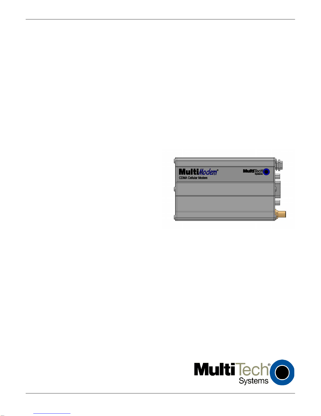
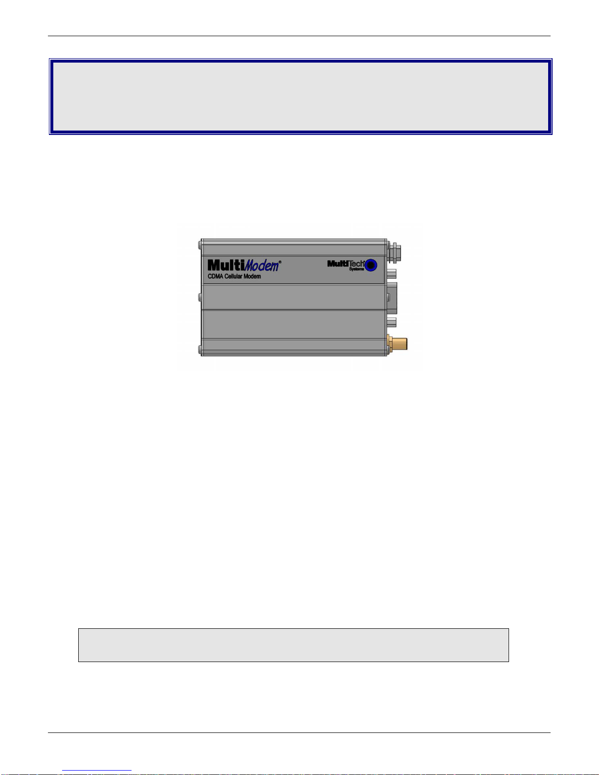
The Multi-Tech MultiModem® CDMA Cellular Modem is an external data only cellular modem. It also supports Short Message
Service (SMS) such as text and PDU mode, point-to-point (MT/MO) and cell broadcast. It offers standards-based dual-band
CDMA2000 1xRTT performance. This ready-to-deploy, standalone modem allows developers to add cellular communication to
products with a minimum of development time and expense. The MultiModem CDMA Cellular Modem is based on industrystandard open interfaces, is fully type approved and can be desktop or panel mounted.
MTCBA-C1X
Features
• CDMA2000 1xRTT
• Dual-band 800/1900 MHz CDMA
• Supports Short Message Service such as text, UCS-2, point-to-point (MT/MO) and cell broadcast
• Available with RS-232 inter fac e
• Packet data up to 153.6K bps
• Circuit-switched data up to 14.4K bps
• IS-95A, IS-95B backwards compatible
• SMA antenna connector
• Configured using CDMA AT commands
• Multiple LEDs provide ongoing operational status
• Over-the-Air activation
• Desktop or panel mounting
• CDG 1 and 2 network certified
• Two-year warranty
Related Documentation
AT Commands: The MultiModem MTCBA-C1X cellular modem is configured using the CDMA AT
Commands. These commands are documented in the Reference Guide for the MultiModem CDMA Modems,
document number S000478x.
4 Multi-Tech Systems, Inc. MultiModem CDMA User Guide
Page 5

Chapter 1 – Product Description and Specifications
Safety
General Safety
The modem is designed for and intended to be used in fixed and mobile applications. “Fixed” means that the device is physically
secured at one location and is not able to be easily moved to another location. “Mobile” means that the device is designed to be
used in other than fixed locations.
Caution: Maintain a separation distance of at least 20 cm (8 inches) between the transmitter’s antenna
and the body of the user or nearby persons. The Modem is not designed for or intended to be used in
portable applications within 20 cm. (8 inches) of the body of the user.
RF Interference Issues
It is important to follow any special regulations regarding the use of radio equipment due in particular to the possibility of radio
frequency, RF, interference. Please follow the safety advice given below carefully.
● Switch OFF your MultiModem when in an aircraft. The use of cellular telephones in an aircraft may endanger the
operation of the aircraft, disrupt the cellular network and is illegal. Failure to observe this instruction may lead to
suspension or denial of cellular telephone services to the offender, or legal action or both.
● Switch OFF your MultiModem when around gasoline or diesel-fuel pumps and before filling your vehicle with fuel.
● Switch OFF your MultiModem in hospitals and any other place where medical equipment may be in use.
● Respect restrictions on the use of radio equipment in fuel depots, chemical plants or where blasting operations are in
progress.
● There may be a hazard associated with the operation of your MultiModem close to inadequately protected personal
medical devices such as hearing aids and pacemakers. Consult the manufacturers of the medical device to determine
if it is adequately protected.
● Operation of your MultiModem close to other electronic equipment may also cause interference if the equipment is
inadequately protected. Observe any warning signs and manufacturers’ recommendations.
Vehicle Safety
● Do not use your MultiModem whil e driving.
● Respect national regulations on the use of cellular telephones in vehicles. Road safety always comes first.
● If incorrectly i nstalled in a vehicle, the operation of MultiModem telephone could interfere with the correct functioning of
vehicle electronics. To avoid such problems, be sure that qualified personnel have performed the installation.
Verification of the protection of vehicle electronics should be part of the installation.
● The use of an alert device to operate a vehicle’s lights or horn on public roads is not permitted.
Maintenance of the Cellular MultiModem
Your cellular MultiModem is the product of advanced engineering, design, and craftsmanship and should be treated with care.
The suggestions below will help you to enjoy this product for many years.
● Do not expose the MultiModem to any extreme environment where the temperature or humidity is high.
● Do not attempt to disassemble the MultiModem. There are no user serviceable parts inside.
● Do not expose the MultiModem to water, rain, or spilled beverage s. It is not waterproof.
● Do not abuse your MultiModem by dropping, knocking, or violently shaking it. Rough handling can damage it.
● Do not place the MultiModem alongside computer discs, credit or travel cards, or other magnetic media. The
information contained on discs or cards may be affected by the phone.
● The use of accessories not authorized by Multi-Tech or not compliant with Multi-Tech’s accessory specifications may
invalidate the warranty of the MultiModem.
● In the unlikely event of a fault in the MultiModem, contact Multi-Tech Technical Support.
Handling Precautions
All devices must be handled with certain precautions to avoid damage due to the accumulation of static charge. Although input
protection circuitry has been incorporated into the devices to minimize the effect of this static build up, proper precautions should
be taken to avoid exposure to electrostatic discharge during handling and mounting.
Multi-Tech Systems, Inc. MultiModem CDMA User Guide 5
Page 6

Chapter 1 – Product Description and Specification
TD
Transmit Data. Light is on when the modem is transmitting data.
RD
Receive Data.
CD
Carrier Detect.
Off state. Modem is off (not ready) or in download mode.
TR
Terminal Ready. Commonly called “Data Terminal Ready.” This is a readiness signal from the PC.
PWR
Power. Light is on continuously to when power on.
with No Accessories
With Accessories
Front Panel
The front panel is designed with LEDs that display modem activity. The LEDs display modem activity, such as transmit and
receive data, carrier detection, link status, terminal ready indicating connection to the pc, and the power indicator.
LEDs
LED Indicators
LS Line Status.
Continuous “on” state - indic ates that the wireless modem is not registered on the network.
Flashing states:
200 ms on / 2 sec off - Indicates registration on network.
200 ms on / 600 ms off - Indicates it is registered on a network and communication is in progress.
Light is on when the mod em is rece iv ing data .
Light is on when a data connection has been established.
Package Contents
Unbundled Package
1 modem
1 mounting bracket
1 MultiModem CD
Note: You must supply mounting screws, AC or DC
power supply, and an antenna.
Bundled Package
1 modem
1 antenna
1 mounting bracket
1 RS232 cable
1 power supply
1 MultiModem CD
Note: You must supply mounting screws.
6 Multi-Tech Systems, Inc. MultiModem CDMA User Guide
Page 7

Specifications
General Specifications
Power Connector
Chapter 1 – Product Description and Specifications
Standards
Band, Frequency
Packet Data
Circuit Switched Data
Short Message Services – SMS
RS232 Connector
Voltage
Power* Sleep: 0.020A, 0.19W @9V Typical: 0.109A, 1.01W @9V
Mechanical Dimensions & Weight
Operating Temperature**
Storage Temperatures
Humidity
Certifications EMC: FCC Part 15
CDMA2000 1xRTT operation
Dual-band 800/1900 MHz CDMA;
800 MHz or 800/1900 MHZ with R-UIM support
Up to 153K bps forward and reverse
IS-95-A, IS-95B up to 14.4K bps forward and reverse
Text & PDU, point-to-point (MO/MT), cell broadcast
DB15
2.5mm miniature (screw-on)
5 V to 32VDC
0.012A, 0.24W @20V 0.054A, 1.08W @20V
0.008A, 0.26W @32V 0.036A, 1.15W @32V
Max: 0.340A, 3.12W @9V
0.175A, 3.50W @20V
0.110A, 3.52W @32V
4.3" L x 2.4" W x 0.94" H; 4.2 oz.
(11 cm x 6.1 cm x 2.4 cm; 119 g)
-40° to +85°C UL listed @ 40° C
-40° to +85°C
Relative humidity 20% to 90% noncondensing
Radio Compliance: FCC Part 22, 24
RSS132, 133
Safety: UL 60950-1 cUL 60950-1, IEC 60950-1
Network: CDG 1 & 2
* Multi-Tech Systems, Inc recommends that the customer incorporate a 10% buffer into their power source when
determining product load.
** UL Listed @ 40° C, limited by power supply. UL Certification does not apply or extend to an ambient above 40° C and
has not been evaluated by UL for ambient greater than 40° C.
“UL has evaluated this device for use in ordinary locations only. Installation in a vehicle or other outdoor locations has
not been evaluated by UL. UL Certification does not apply or extend to use in vehicles or outdoor applications or in
ambient above 40° C.”
Multi-Tech Systems, Inc. MultiModem CDMA User Guide 7
Page 8

Chapter 1 – Product Description and Specification
CDMA 800
CDMA 1900
Frequency RX
869 to 894 MHz
1930 to 1990 MHz
Frequency TX
824 to 849 MHz
1850 to 1910 MHz
Typical Radiated Gain
Radiation
Cellular Information
Antenna System for Cellular Devices
The cellular performance is completely dependent on the implementation and antenna design. The integration of the antenna
system into the product is a critical part of the design process; therefore, it is essential to consider it early so the performance is
not compromised. If changes are made to the certified antenna system of the MultiModem, then recertification will be required
by specific network carriers such as Sprint. The Antenna System is defined as the UFL connection point from the MultiModem
to the specified cable specification s and specified antenna specifications.
PTCRB Requirements for the Antenna
There cannot be any alteration to the authorized antenna system. The antenna system must maintain the same specifications.
The antenna must be the same type, with similar in-band and out-of-band radiation pattern s.
FCC Requirements for the Antenna
The antenna gain, including cable loss, for the radio you are incorporating into your product design must not exceed the
requirements at 850 MHz and 1900 MHz as specified by the FCC grant for mobile operations and fixed mounted operations as
defined in 2.1091 and 1.1307 of the FCC rules for satisfying RF exposure compliance. The antenna used for transmitting must
be installed to provide a separation distance of at least 20cm from all persons and must not transmit simultaneously with any
other antenna transmitters. User and installers must be provided with antenna installation instructions and transmitter operating
conditions to satisfying RF exposure compliance.
Antenna Specifications
CDMA RF Specifications
CDMA Antenna Requirements/Specifications
Frequency Range
Impedance
VSWR
Polarization
Antenna Loss
TRP/TIS
824 – 894 MHz / 1850 – 1990 M Hz
50 Ohms
VSWR shall not exceed 2.0:1 at any point across the bands of operati on
3 dBi on azimuth plane
Omni-directional
Vertical
Free space not to exceed -3dB
The total radiated power (TRP) at the antenna shall be no less than
+21/20 dBm for PCS/Cell channels respectively, and the total isotropic
sensitivity (TIS) at the antenna shall be no less than -104/104 dBm for
PCS/Cell channels respectively.
RS232 15-Pin Connector
The following table explains the pin functions.
PIN EIA CCIT Designation
RS-232 1 DCD 109 Data Carrier Direct
6 RX 104 Receive Data (out)
2 TX 103 Transmit Data
8 DTR 108.2 Data Terminal Ready
9 GND Signal Ground
7 DSR 107 Data Set Ready
12 RTS 105 Request to Send
11 CTS 106 Clear to Send
13 RI 125 Ring Indicator
Reset 14 RESET To reset, connect to GND momentarily
(typical: 20mSec). Open for normal
operation.
8 Multi-Tech Systems, Inc. MultiModem CDMA User Guide
Page 9

Chapter 2 – Installation
Connect the Antenna, Serial and Power Cables
1. Connect a suitable antenna to the ANT connector on the back of the unit, refer to Cellular Information in Chapter 1 for
antenna specifications.
2. Connect a serial cable to the RS232 connector on the b ac k of the unit and connect the other end of the cable to the
serial port on your PC.
3. Depending on the power source, connect either the power supply module with the appropriate blade or a customer-
supplied DC power cable. If you are using the power supply module, remove the pr ote ctiv e shippin g cov er. Atta ch the
appropriate interchangeable blade piece to the power supply module.
4. Screw-on the power lead from the power supply modu le to the power connection on the modem. Now, plug the power
supply into your power source.
For customer-supplied DC Power
● Screw-on a customer-supplied DC power cable to the power connector on the modem.
● Then attach the two wires at the other end of the DC power cable to a DC fuse/terminal block.
● Connect the red wire to the "+" (positive) terminal and the black wire to the "–" (negative) terminal. Be sure the
GND connection is correct.
Warning: Over-voltage protection is provided on the device. To ensure complete protection, you may want to add
additional filtering to the DC input.
Note: For automotive application: according to the type of application, you can use permanent “+” or key-switched “+”
source. Connect the power supply to its source (for example, in a mobile situation, to the vehicle’s D C
fuse/terminal block).
Powering Down and Hardware Resetting a MTCBA-C1X Modem
It is recommended to follow the following shutdown sequence, when possible, prior to a hardware
reset or turning off of power to the modem.
The shutdown sequence informs the network that the mobile station is going offline, and saves
critical data to the module‘s non-volatile mem ory (fla sh).
AT+CFUN=0 (issue this command)
+WIND:10 (Wait for this response from the modem)
Modem is now ready to be powered off or reset.
If you do not see the +WIND:10 response, you may need to activate the unsolicited message by
using the command AT+WUSLMSK=00020000,0
Multi-Tech Systems, Inc. MultiModem CDMA User Guide 9
Page 10

Chapter 2 - Installation
Optional Mounting
Before you mount your modem to a permanent surface, ensure that you have a strong enough (average) signal, refer to Verify
Signal Strength in Chapter 3.
Once you have verified that you have a good signal, you can panel mount your modem with the screws spaced according to
the measurement shown below.
Note: Use, for example, two 6-3 self-tapping screws 5/8” in length to mount the unit.
10 Multi-Tech Systems, Inc. MultiModem CDMA User Guide
Page 11

Chapter 2 - Installation
Install the Modem Driver
The cellular modem is compatible with Windows 7, Vista, XP, 2003 Server, and 2008 Server (32-bit or 64-bit). Linux does not
require a driver for serial modems.
Windows operating systems require a modem driver to be installed in your computer’s program directory. The Windows driver is
located on your MultiModem product CD. Refer to the example below for installing the Windows driver onto your PC.
To load the modem’s driver on to your PC, select the Control Panel’s Phone and Modem Options option. During this installation,
you will be required to browse to the MultiModem CD to load the modem’s .inf file. This file is located in the Drivers folder on the
MultiModem CD.
1. Go to Start, and then click on Control Panel.
2. In the Control Panel, double-click on Phone and Modem Options.
3. When the Phone and Modem Options screen appears, click on the tab labeled Modems.
Click on Add to add a new modem.
Multi-Tech Systems, Inc. MultiModem CDMA User Guide 11
Page 12

Chapter 2 - Installation
4. On the Install New Modem screen, click Don’t detect my modem, I will select it from a list.
Then click Next >.
5. On the Install New Modem screen, click the Have Disk button to browse to the driver file on the MultiModem CD.
6. Make s ure that the MultiModem CD is inserted into your CD-ROM.
12 Multi-Tech Systems, Inc. MultiModem CDMA User Guide
Page 13

Chapter 2 - Installation
7. Browse to your MultiModem CD and select Drivers/Windows Drivers.
Then select MTSWireless file.
8. On Install New Modem screen, scroll down the list of modems and select MultiTech – CDMA Modem.
Once you have selected your model, click on Next>.
Multi-Tech Systems, Inc. MultiModem CDMA User Guide 13
Page 14

Chapter 2 - Installation
9. Choose w hich com port to co nnec t your MultiModem to.
If you know exactly which port your modem is on, click on that port; other wise, choose COM2 (most common). Click
Next >.
10. To finish the install, click on Finish.
You have now successfully installed the MultiModem.
Verifying That Your Modem Has Been Installed Successfully
1. After you have successfully installed the Multi-Tech modem driver as stated above, you should be brought back to the
Phone and Modems Options screen. Make sure that the modem is now listed under the columns Modem and
Attached To (the correct com port).
2. Highlight the modem and then click Properties.
3. A Properties screen will open for the Multi-Tech modem. Click on the tab labeled Diagnostics.
4. In the middle of the screen, click on the Query Modem button. Windows will now try to query the Multi-Tech modem. If
this process passes, the second box on this screen will show the columns Command and Response.
Note: To make sure that the modem is correctly being queried, look at the LED lights of the modem after you click on
Query Modem. The TR light should come on and the TD and RD lights should flicker.
5. If this process passes, then the modem should be properly installed and ready for use. Click OK to close the modem
Properties window. Then click on OK to close the Phone and M odem Options window.
14 Multi-Tech Systems, Inc. MultiModem CDMA User Guide
Page 15

Chapter 3 – Using Your Cellular Modem
Signal Strength Verification – RSSI
AT+CSQ xx Values
Signal Strength
0 - 10
Weak or Insufficient
11 - 20
Average
21 – 31
Exceptional
99
No signal
Account Activation for Wireless Devices
Please refer to Multi-Tech’s Cellular Activation Web site at http://www.multitech.com/activation.go for information on activating
your cellular modem.
Verify Signal Strength
Before you mount your modem to a permanent surface, ensure that you have a strong enough (average) signal.
1. Using Hyperterminal or an equivalent terminal program, type AT+CSQ. The modem responds with the receive signal
strength (rssi).
2. Once you have a good signal for where you are going to permanently mount the modem, refer back to Optional
Mounting in Chapter 2.
Connecting to the Internet
Internet access can be setup in Windows Dial-Up Networking (DUN) of the computer that the MultiModem is serving.
Connecting to a CDMA Network for Internet Access
Once you have activated your cellular account, you can establish your Internet connection through a Windows dial-up session.
Requirements
● One CDMA capable MultiModem modem
● The modem must be getting a proper signal and be showing a netw ork regis tr ati on thr oug h the cellular provider’s
network.
● A PC running Windows 7, Vista, or XP with the Multi-Tech drivers installed for your particular model.
The following instructions are for Windows7, Vista, or XP. Every PC may have slight differences which may cause the
instructions to be different. Use these instructions as a guide to help you understand what is required to set up an Internet
connection through your cellular service provider for all operating systems.
Create Your Dial-Up Connection in Windows Vista and XP
1. Click on Start and then click on Control Panel.
2. In the Control Panel, double-click on Network Connections.
3. On the Network Connections screen on the left-hand side under Network Tasks, click on Create a new
connection.
4. The New Connection Wizard should appear. It will walk you through setting up your Internet connection. Click on
Next > to begin.
5. On the Network Connection Type screen, select Connect to the Internet, and then click Next >.
6. On the Getting Ready s cree n, sele ct Set up my connection manually, and then click Next >.
7. On the Internet Connection screen, select Connect using a dial-up modem, and then click Next >.
Note: After clicking on Next, you may or may not be asked to select which modem to use. If you have more than one
modem installed in your PC, you will be required to select the proper modem to use. If asked, please select the MultiTech cellular modem that has been installed.
8. On the Connection Name screen in the ISP Name box, type in a name for your new connection. You can give it any
name that you would like. After you have typed in a name, click Next >.
9. On the Phone Number to Dial screen, type in the number that specifies to the modem to connect to your provider’s
Internet service.
Type in the number #777.
Then click Next >.
Multi-Tech Systems, Inc. MultiModem CDMA User Guide 15
Page 16

Chapter 3 – Using your Cellular Modem
10. On the Connection Availability screen, specify if this connection is for anyone’s use or for your use only by checking
the appropriate button. Choose your preference, and then click Next>.
11. On the Internet Account Information screen, type the user name and the password for your account. In many cases,
a user name and a password are not required, but some cellular providers require it. Check with your provider to see
if they are needed.
Check the following two options if you would like them activated:
Check the box if you want this account name and password to be used by everyone.
Check the box if you want this as your default Internet connection. Then click Next >.
12. On the Completing the New Connection Wizard screen, your last task is to place a check in the box i f you would like
to add a shortcut to your desktop. Then click Finish.
13. A Connection screen displays on your desktop. Click the Properties button on the bottom of this screen.
14. The Properties window will open for you to make your connection.
Important: Make sure that Use dialing rules is not select ed, and th en click OK.
15. Once back at your Connection screen, clic k the Dial button at the bottom of the screen to start the connection.
16. The connection will now tell the modem to connect to your provider’s Internet service. Once connected, you should
see the connection status icon in your system tray at the bottom right-hand corner of your screen.
You should now be able to open Internet Explorer or any other browser of your preference to surf the Internet.
Disconnecting the Connection:
1. To disconnect the connection, right click on the connection icon in your system tray at the bottom right-hand corner
of your screen.
2. Scroll up and click on Disconnect.
You should now be disconnected from the Internet.
16 Multi-Tech Systems, Inc. MultiModem CDMA User Guide
Page 17

Appendix A – Regulatory Compliance
EMC, Safety, and R&TTE Directive Compliance
The CE mark is affixed to this product to confirm compliance with the following European Community Directives:
Council Directive 2004/108/EC of 31 December 2004 on the approximation of the laws of Member States relating to
electromagnetic compatibility;
and
Council Directive 2006/95/EC of 12 December 2006 on the harmonization of the laws of Member States relating to electrical
equipment designed for use within certain voltage limits;
and
Council Directive 1999/5/EC of 9 March 1999 on radi o equip ment and telecommunications terminal equ ipm ent and the
mutual recognition of their conformity.
International Modem Restrictions
Some dialing and answering defaults and restrictions may vary for international modems. Changing settings may cause a
modem to become non-compliant with national telecom requirements in specific countries. Also note that some software
packages may have features or lack restrictions that may cause the modem to become non-compliant.
FCC Part 15 Class B Statement
This equipment has been tested and found to comply with the limits for a Class B digital device, pursuant to 47 CFR Part 15
regulations. The stated limits in this regulation are designed to provide reasonable protection against harmful interference in a
residential installation. This equipment generates, uses, and can radiate radio frequency energy, and if not installed and used in
accordance with the instructions, may cause harmful interference to radio communications. However, there is no guarantee that
interference will not occur in a particular installation. If this equipment does cause harmful interference to radio or television
reception, which can be determined by turning the equipment off and on, the user is encouraged to try to correct the interference
by one or more of the following measures:
● Reorient or relocate the receiving antenna.
● Increase the separation between the equipment and receiver.
● Plug the equipment into an outlet on a circuit different from that to which the receiver is connected.
● Consult the dealer or an experienced radio/TV technician for help.
This device complies with Part 15 of the CFR 47 rules. Operation of this device is subject to the following conditions: (1) This
device may not cause harmful interference, and (2) this device must accept any interference that may cause undesired
operation.
Warning: Changes or modifications to this unit not expressly approved by the party responsible for compliance could void the
user’s authority to operate the equipment.
Industry Canada
This Class B digital apparatus meets all requirements of the Canadian Interference-Causing Equipment Regulations.
Cet appareil numérique de la classe B respecte toutes les exigences du Reglement Canadien sur le matériel brouilleur.
Multi-Tech Systems, Inc. MultiModem CDMA User Guide 17
 Loading...