

Page 1

MT56DSU2 Owner’s Manual
MultiDSU56K
Model MT56DSU2
Owner’s Manual
82017502 1
Page 2

MT56DSU2 Owner’s Manual
MultiDSU56K
Model MT56DSU2
Owner’s Manual
P/N 82017502 Rev. C
This publication may not be reproduced, in whole or in part, without prior expressed written
permission from Multi-Tech Systems, Inc. All rights reserved.
Copyright 1993, by Multi-Tech Systems, Inc.
Multi-Tech Systems, Inc. makes no representation or warranties with respect to the contents
hereof and specifically disclaims any implied warranties of merchantability or fitness for any
particular purpose. Furthermore, Multi-Tech Systems, Inc. reserves the right to revise this
publication and to make changes from time to time in the content hereof without obligation of
Multi-Tech Systems, Inc. to notify any person or organization of such revisions or changes.
Record of Revisions
Revision Date
Description
A 10/01/92 Manual released. All pages at Revision A.
B 06/01/93 Manual revised with minor editorial changes.
C 09/07/93 Manual revised to add cable part numbers and build instructions.
TRADEMARKS
Multi-Tech and the Multi-Tech logo are trademarks of Multi-Tech Systems, Inc.
DATAPHONE is a registered trademark of AT&T.
Multi-Tech Systems, Inc.
2205 Woodale Drive
Mounds View, Minnesota 55112 U.S.A.
(763) 785-3500 or (800) 328-9717
U.S. Fax (763) 785-9874
Technical Support (800) 972-2439
www.multitech.com
82017502 2
Page 3

MT56DSU2 Owner’s Manual
Table of Contents
CHAPTER 1-INTRODUCTION AND DESCRIPTION
1.1 Introduction 5
1.2 About This Manual 5
1.3 Description 5
1.4 CSU/DSU Basics 6
1.5 Features 7
1.6 FCC Regulations for Telephone Line Interconnection 8
1.7 Specifications 9
CHAPTER 2- HARDWARE INSTALLATION
2.1 Introduction 10
2.2 Default DIP Switch Settings 10
2.3 Changing Default Settings 11
2.4 Installation Procedure 12
CHAPTER 3- OPERATION
3.1 Introduction 14
3.2 Options 14
3.2.1 Data Rate 14
3.2.2 Async/Sync 14
3.2.3 Anti-Streaming 15
3.2.4 Elastic Store 15
3.2.5 System Status 15
3.2.6 Circuit Assurance 15
3.2.7 Clocking (Inte rnal, External orDDS) 15
3.2.8 RTS Forced On 16
3.2.9 DSR Forced On 16
3.2.10 Async Word Length (9/10/11 Bit) 16
3.2.11 Normal/Diagnostics 16
3.3 LED Indicators 16
3.4 Functions 17
3.4.1 LADS Applications 17
3.4.2 Off-Net Extension Applications 17
CHAPTER 4- TROUBLESHOOTING
4.1 Introduction 18
4.2 LED Indicators 18
4.2.1 SD Indicator 18
4.2.2 RD Indicator 18
4.2.3 CD Indicator 18
4.2.4 56K Indicator 19
4.2.5 19.2 Indicator 19
4.2.6 96 Indicator 19
4.2.7 48 Indicator 19
4.2.8 CTS Indicator 19
4.2.9 RTS Indicator 20
4.2.10 NS Indicator 20
4.2.11 005 Indicator 20
4.2.12 TM Indicator 20
4.3 Diagnostic Tests 20
4.3.1 Local Loopback Test 20
4.3.2 Digital Loopback Test 21
4.3.3 Digital Loop Test With Test Pattern Test 22
4.3.4 Test Pattern Test 22
4.3.5 DSU Loopback Test 23
4.3.6 DSU Back-to-Back Test 23
CHAPTER 5- SERVICE, WARRANTYAND TECH SUPPORT
5.1 Service 24
5.2 Limited Warranty 24
5.3 Tech Support 25
5.4 Recording DSU Information 25
APPENDICES
Appendix A — Application Examples 26
Appendix B — Interface Signals and Connector Pinouts 30
GLOSSARY 35
82017502 3
Page 4

MT56DSU2 Owner’s Manual
Chapter 1 - Introduction and Description
1.1 Introduction
Congratulations! Your new MultiDSU56K is one of the finest DSU/CSUs available today. As a
combined CSU (Channel Service Unit) and DSU (Data Service Unit), it provides a direct
connection to the DATAPHONE® Digital Service (DDS) network. The MultiDSU56K co nn ect s a
computer or Data Terminal Equipment (DTE) to remote equipment using DDS network lines at
2400, 4800, 9600, 19200 and 56000 bps speeds for point-to-point and multi-point service.
1.2 About This Manual
This manual contains five chapters and two appendixes. In addition, there is a Glossary and an
Index at the end of this manual. The information in this manual is provided as described below.
Chapter 1 - Introduction and Description contains an introduction to the MultiDSU56K product
and its features and functions.
Chapter 2 - Hardware Installation provides configuration and installation procedures.
Chapter 3 - Operation describes the functional features and options of the MultiDSU56K.
Chapter 4 - Troubleshooting explains what to do if your MultiDSU56K encounters problems in
operation.
Chapter 5 - Service, Warranty and Tech Support defines procedures to follow if the
troubleshooting steps in Chapter 4 do not fix the problem.
Appendix A - Applications Examples illustrates several DSU/CSU uses that may help in
understanding your part icular in sta ll ati on si te.
Appendix B - Interface Signals lists the various electronic signals and connector pinouts related
to the MultiDSU56K.
Glossary - defines the technical terms used in this manual.
1.3 Description
The MultiDSU56K is compact, easy to operate and has the features to allow flexibility in meeting
your transmission requirements. The DDS is a service for transmission of digital signals via digital
transmission facilities exclusively. The MultiDSU56K is designed to meet AT&T Technical
Publication 62310 requirements. As such, the MultiDSU56K provides all of the functions required
on the customer side of the network.
The MultiDSU56K provides user selection of sync hron ous data communication s at rates of 2400,
4800, 9600, 19200 and 56000 bps, and asynchronous data communications rates up to 19200
bps. It provides three separate interface connections (RS232C, V.35 and DDS).
You will find the MultiDSU56K easy to install, use and maintain. It is recommended that you read
the entire manual early in your experience with the MultiDSU56K so you can appreciate all of the
MultiDSU56K features and options.
82017502 4
Page 5
MT56DSU2 Owner’s Manual
MultiDSU56K
SD
Send Rcv Carrier 56K 19.2K 9600 4800 Clear Request NoSgnl Outage Test
CD
RD
19.2
56
48
96
CTS
RTS
DOS
NS
TM
Multi-Rate DSU/CSU
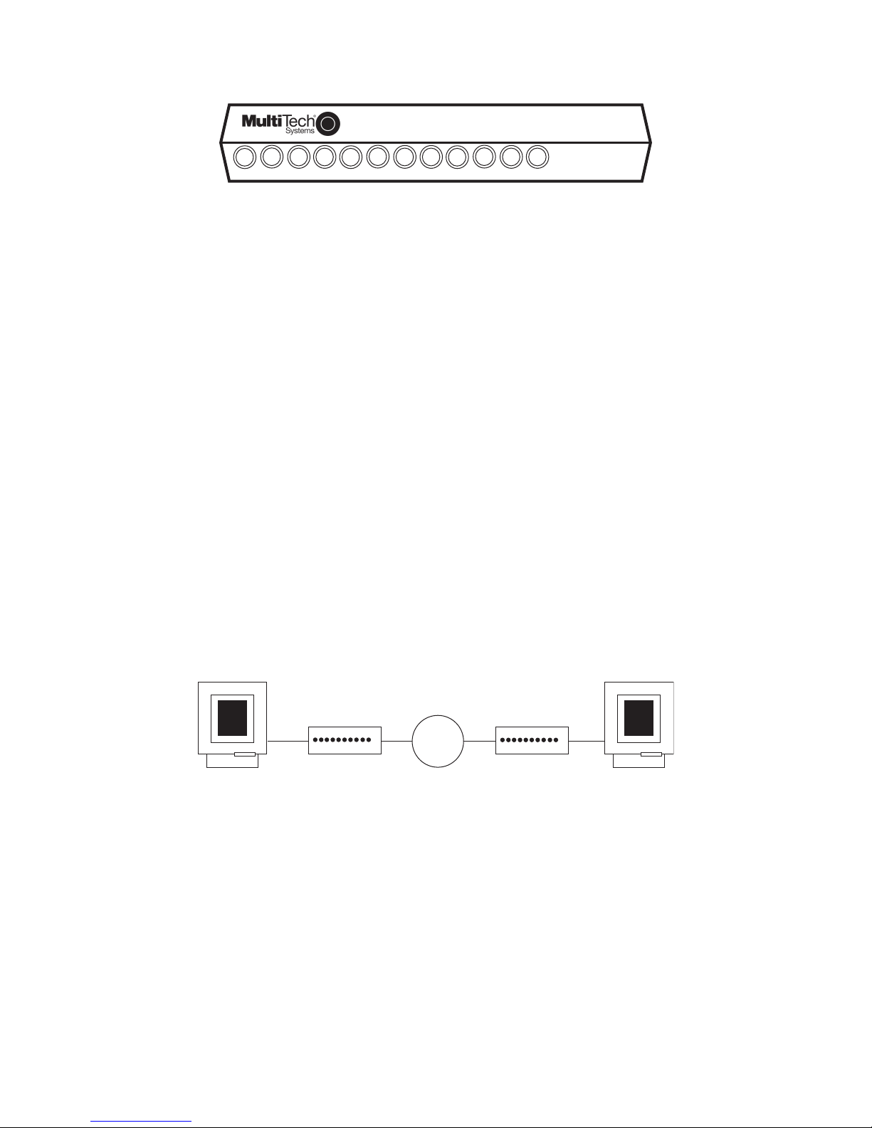
Figure 1-1. Multi-Tech System’s MultiDSU56K
1.4 CSU/DSU Basics
A DSU (Data Service Unit) and a CSU (Channel Service Unit) are typically connected to provide
the interface between DTE (data terminal equipment) and the DDS (Digital Data Service) or other
four-wire network.
The DSU is used to process serial synchronous or asynchronous digital data over the DDS
network or other four-wire unloaded twisted-pair wiring network.
The MultiDSU56K can transmit data at 56000, 19200, 9600, 4800 and 2400 bps in multi-point
and point-to-point applicati on s.
The MultiDSU56K contains the functions of a Data Service Unit (DSU) and a Channel Service
Unit (CSU) in a single package.
1.4.1 DSU Functions
The DSU encodes data as pulses on the communications line by converting the customer data
stream to bipolar format for transmission over the digital network.
1.4.2 CSU Functions
The CSU is used to terminate the digital circuit at the customer site. It performs line conditioning
functions, ensures network compliance with FCC rules, and responds to test commands (either
from the telco central office (CO) or from the CSU).
The figure below shows the MultiDSU56K in a basic DDS network installation.
DDS
Network
DTE
MultiDSU56K
MultiDSU56K
Figure 1-2. Basic DSU/CSU Configuration
DTE
82017502 5
Page 6

MT56DSU2 Owner’s Manual
1.5 Features
The MultiDSU56K provides many useful features. Standard features include V.35 and RS232
connections and either synchronous or asynchronous transmission; synchronous at rates up to
56000 bps and asynchronous up to 19200 bps; selectable digital rates that match the services
offered by the carriers. Other features include user-selectable clocking options, elastic store for
analog off-net extensions, anti-streaming, and RTS and DSR signal forced on selection.
Your MultiDSU56K provides the following features:
• supports direct connection to the DATAPHONE Digital Data Service (DDS) or compatible
network
• selectab le s ync spe ed s of 2400, 4800 , 9600, 192 00 and 560 00 bps
• selectable async speeds of 2400, 4800, 9600, and 19200 bps
• point-to-point and multipoint operation
• Standard RS232C, V. 35 and DDS int erfaces provided
• anti-streaming (for multi-point operations)
• elastic store (for analog off-net extensions)
• system stat us
• circuit assurance
• multiple se lectable clockin g
* External clocking
* Internal clocking
* DDS (slave) clocking
• RTS signa l forced on se le cti on
• DSR signal forced on selection
• multiple MultiDSU56K-activated diagnostic tests:
* Local loopback test
* Digital loopback test
* Test pattern generator/detector
• multiple Telco-activated diagnostic tests:
* DSU loopback test
* CSU loopback test
82017502 6
Page 7

MT56DSU2 Owner’s Manual
1.6 FCC Regulations for Telephone Line Interconnection
1. This equipment complies with Part 68 of the FCC rules. On the outside surface of this
equipment is a label that contains, among other information, the FCC registration number and
ringer equivalence number (REN). If requested, this information must be provided to the
telephone company.
2. As in di cat ed bel ow, the su itab le jack (USOC) connecting ar r ang eme nt for this equipment is
shown in Appendix B. If applicable, the facility interface codes (FIC) and service order codes
(SOC) are also indicated.
3. The ringer equivalence number (REN) is used to determine the quantity of devices which may
be connected to the telephone line. Excessive REN’s on the telephone line may result in the
devices not ringing in response to an incoming call. In most, but not all areas, the sum of the
REN’s should not exceed five (5.0). To be certain of the number of devices that may be
connected to the line, as determined by the total REN’s, contact the telephone company to
determine the maximum REN for the calling area.
4. If this equipment causes harm to the telephone network, the telephone company will notify you
in advance. But if advance notice isn’t practical, the telephone company will notify the
customer as soon as possible. Also, you will be advised of your right to file a complaint with the
FCC if you believe it is necessary.
5. The telephone company may make changes in its facilities, equipment, operations, or
procedures that could affect the operation of the equipment. If this happens, the telephone
company will provide advance notice in order for you to make necessary modifications in order
to maintain uninterrupted service.
6. If trouble is experienced with this equipment (the model of which is indicated below) please
contact Multi-Tech Systems, Inc. at the address shown below for details of how to have repairs
made. If the trouble is causing harm to the telephone network, the telephone company may
request you remove the equipment from the network until the problem is resolved.
7. No repairs are to be made by you. Repairs are to be made only by Multi-Tech Systems or its
licensees. Unauthorized repairs void registration and warranty.
8. This equip me n t can not be con ne cte d to publi c co in ser vi ce pr ovid ed b y the teleph one
company. (Contact the state pub li c uti lit y co mmission, public ser vice co mm is s ion or
corporation commission for information.)
Manufacturer: Multi-Tech System s, Inc.
Model Number: MT56DSU2
FCC Pt 68 Registration #: AU7USA-18883-DE-N
Ringer Equivalence: N/A
SOC Codes: 6.0N
Modular jack (USOC): RJ48S
Service Center in U.S.A.: Multi-Tech Systems, Inc.
2205 Woodale Drive
Mounds View, MN 55112 USA
(763) 785-3500 or (800) 328-9717
U.S. Fax (763) 785-9874
82017502 7
Page 8

MT56DSU2 Owner’s Manual
1.7 Specifications
Model Number MT56DSU2
Device Operation combined DSU and CSU
Data Rates
Synchronous: 2400, 4800, 9600, 19200, 56000 bps
Asynchronous: 2400, 4800, 9600, 19200 bps
Interfaces
RS232C DB25S (f emale)
V.35 34-pos. rectangular (female)
DDS RJ48 8-position keyed jack
Power Requirements 117V AC, 50-60 Hz, 10 Watts
Temperature 0 to 50 degrees C
Humidity 95% (non-condensing)
Dimensions 1.38" H x 6.15" W x 9" D
3.5 cm H x 15.6 cm W x 22.9 cm D
Weight 2 Lbs. (.9 Kg.) without power transformer
2.7 Lbs. (1.2 Kg.) with power transformer
Certification FCC Part 15 Class A
FCC Part 68
UL Listed
Compatibility AT&T Pubs 62310 and 41450
FIC Codes 04DU5-24 2.4 Kbps digital interface
04DU5-48 4.8 Kbps digital interface
04DU5-96 9.6 Kbps digital interface
04DU5-19 19.2 Kbps di git al int er fa ce
04DU5-56 56 Kbps digital interface
USOC Jack RJ48S
Transmitter/Receiver:
Modulation bipolar return to zero
Transmit Level 1.4V peak (+6dBm) into 135 Ohm at
2400, 4800, 19200, and 56000 bps
0.7V peak (0 dBm) into 135 ohm at
9600 bps
Output Impedance 135 ohms
Receive Levels +6 to -40 dBm at 2400 bps
+6 to -40 dBm at 4800 bps
0 to -40 dBm at 9600 bps
+6 to -40 dBm at 19200 bps
+6 to -45 dBm at 56000 bps
Input Impedance 135 ohms
82017502 8
Page 9

MT56DSU2 Owner’s Manual
Delay Times (in secs.):
RTS/CTS
DCD on DCD off
2400 8.1 7.5 7.0
4800 4.3 2.6 3.5
9600 2.2 1.6 1.5
19200 1.0 0.8 0.7
56000 0.4 0.3 0.2
82017502 9
Page 10

MT56DSU2 Owner’s Manual
Chapter 2 – Hardware Installation
2.1 Introduction
This chapter provides the information needed to configure and install the MultiDSU56K. This manual
assumes the reader is familiar with the function and operation of data communications equipment and is
technically qualified to provide installation service.
Safety Warning Telecom
1. Never install telephone wiring during a lighting storm.
2. Never install telephone jacks in wet locations unless the j ack is specifically designed for wet locations.
3. This product is to be used with UL and cUL listed computers.
4. Never touch uninsulated telephone wires or terminals unless the telephone line has b een disco nnected at
the network interface.
5. Use caution when installing or modifying telephone lines.
6. Avoid using a telephone (other than a cordless type) during an electrical storm. There may be a remote
risk of electr ical shock from lightning.
7. Do not use the telephone to report a gas leak in the vicinity of the leak.
8. To reduce the risk of fire, use only No. 26 AWG or larger Telecommunication line Cord.
2.2 Default DIP Switch Settings
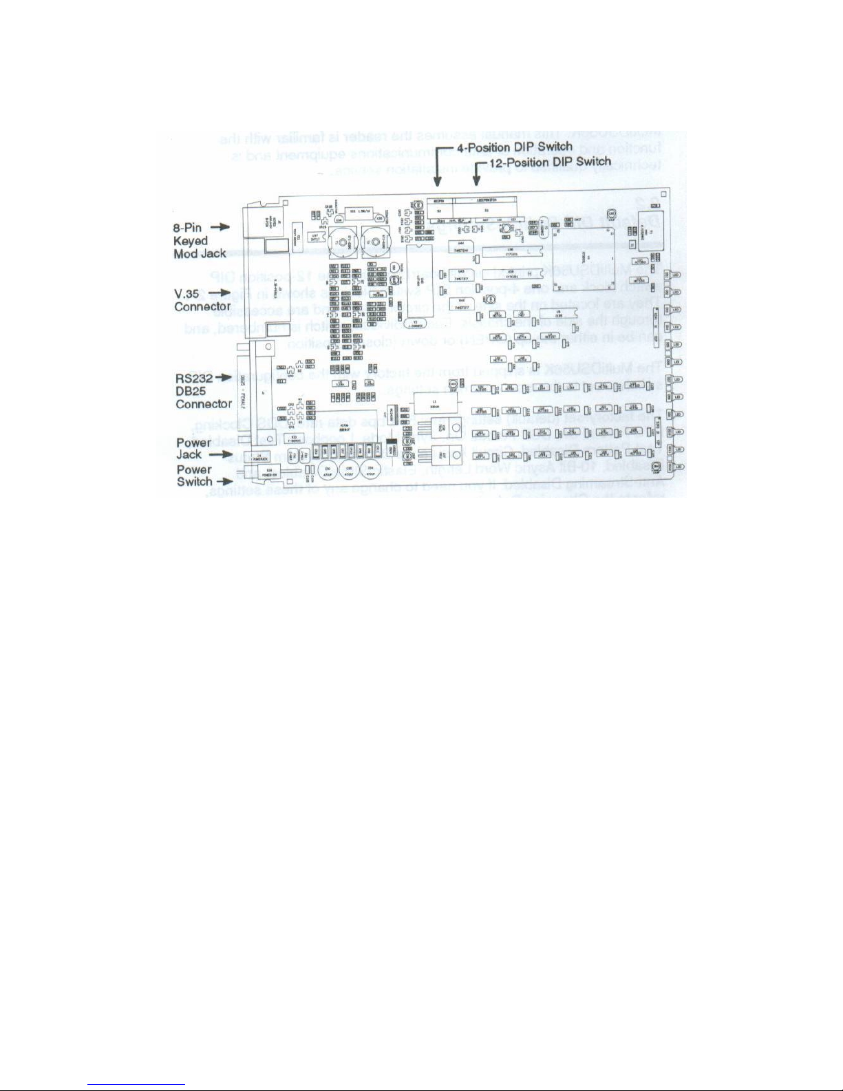
The MultiDSU56K printed circuit board contains one 12-position DIP switch block and one 4-position DIP
switch block as shown in Figure 2-1. They are located on the side of the circuit board, and are accessible
through the side of the chassis. Each individual switch is numbered, and can be in either the up (OPEN) or
down (closed) position.
The MultiDSU56K is shipped from the factory with the configuration DIP switches set to the most
common settin gs.
The factory-set (default) settings are: 56K bps data rate, DDS Clocking, RTS Forced On, DSR Forced On,
Sync Mode, Loopback Test Disabled, Test Pattern Disabled, Circuit Assurance Disabled, System Status
Disabled, 10-Bit Async Word Length, Elastic Store Disabled, and Anti-Streaming Disabled. If you need to
change any of these settings, refer to the Changing Defaults sections below.
82017502 10
Page 11
MT56DSU2 Owner’s Manual
The Mu11iDSU56K DIP switches are shown and described below.
Figure 2-1 MuIttDSU56K Board Layout
2.2.1 12-Position DIP Switch (#1-12 )
The 12-position DIP switch is used to select the data rate, clocking, RT S control, DSR control, AsynclSync
operation, diagnostic modes (Loopback Test, Test Pattern), Circuit Assurance, and System Status. The
default settings are shown in Table 2-1. If you want to make changes to one of these settings, refer to
section 2.3.
2.2.2 4-Position DIP Switch (#13-16)
The 4-position DIP switch is used to select Async Word Length, Elastic Store, and Anti-Streaming options.
The defaults are 10-Bit Async Word Length, Elastic Store disabled, and Anti-Streaming disabled. If
changes to these settings are required, refer to section 2.3.
2.3 Changing the Default DIP Switch Settings
Use Table 2-1 to determine the DIP switch setting changes required for your MultiDSU56K to operate in
your partic ular environment. You may want to re cord your swi t ch setting c hanges for future reference (e.g.,
troubleshooting, equipment moves/changes, calling Tech Support). The DIP switches are illustrated in
Figure 2-1.
82017502 11
Page 12
MT56DSU2 Owner’s Manual
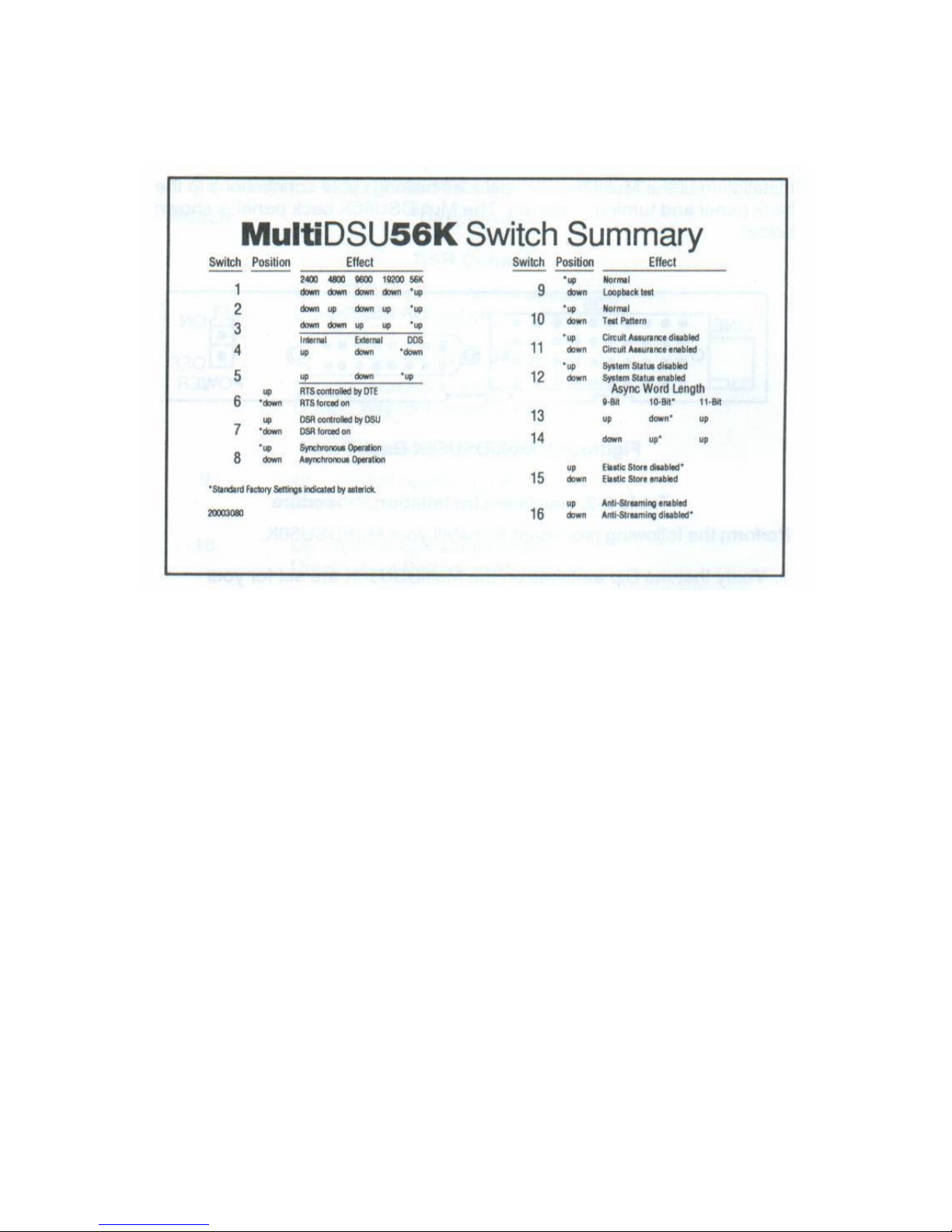
An adhesive-backed label containing the DIP switch setting information is provided o n the bottom of the
MultiDSU56K; a sample label is shown below for reference.
82017502 12
Page 13

MT56DSU2 Owner’s Manual
The factory default settings are indicated by an * in table 2-1.
Table 2-1. MuII1DSU56K Switch Settings
Switch Description
Data Rate (in bps)
2400 4800
9600 19.2K 56K
1 Down Down Down Down Up*
2 Down Up Down Up Up*
3 Down Down Up Up Up*
Clocking
Internal External
DDS
4 Up Down Down *
5 Up Down Up *
RTS Control
6 Up - RTS controlled by DTE
Down - RTS forced On *
DSR Control
7 Up – DSR controlled by DTE
Down – DSR forced on *
Sync / Async Operation
8 Up – Synchronous operation *
Down - Asynchronous operation
Normal / Loopback Test Mode
9 Up – Normal operation *
Down – Loopback Test
Normal / Test Pattern
10 Up – Normal *
Down – Test Pattern
Circuit Assurance Enabled/Disabled
11 Up – Circuit Assurance Disabled *
Down - Circuit Assurance Enabled
System Status Enabled/Disabled
12 Up - System Status Disabled *
Down - System Status Enabled
Async Word Length
9-Bit 10-Bit*
11-Bit
13 Up Down * Up
14 Down Up * Up
Elastic Store Enabled/Disabled
15 Up - Elastic Store Disabled *
Down - Elastic Store Enabled
Anti-Streaming Enabled/Disabled
16 Up - Anti-Streaming Enabled
Down - Anti-Streaming Disabled *
____________________________
* Factory default setting
82017502 13
Page 14
MT56DSU2 Owner’s Manual
2.4 Installation Procedure
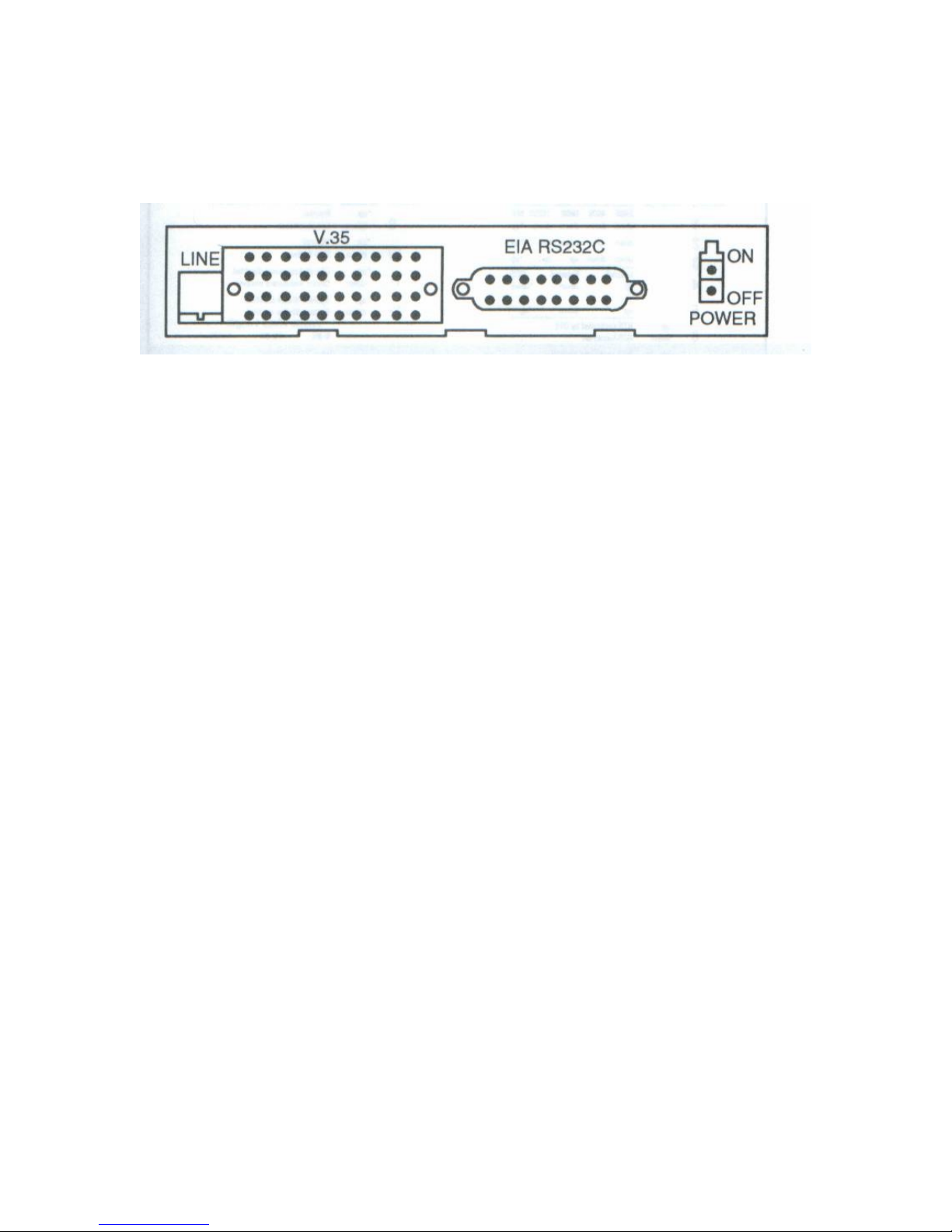
Installation of the MultiDSU56K includes making cable connections to the back panel and turnin g power
on. The MultiDSU56K back panel is shown below.
Figure 2-2. MultiDSU56K Back Panel
Perform the steps below to install the MultiDSU56K.
Table 2-2. Hardware Installation Procedure
Perform the following procedure to install your MultiDSU56K.
1. Verify that the Dip switches on the MultiDSU56K are set for your particular configurations; refer
to Table 2-1.
2. Connect the appropriate MultiDSU56K back panel DTE interface connector, dep e nding on the
DTE:
• Connect the RS232C connector to the 25-pin DB25S receptacle. Use the two screws to secure
the connection, or
• Connect the 34-position rectangular V.35 connector to the V.35 receptacle.
3. Connect the “LINE” Jack of the MuIt1DSU56K to the DDS receptacle using the line cord
provided with the MultiDSU56K.
Note: any cables connected to the computer should be shielded to reduce interference.
4. Connect the other end of the interface cable to the DTEs port connector.
5. Plug in the MultiDSU56K Power Cord into the POWER jack on the MultiDSU56K back panel.
6. Plug the power transformer into an appropriate electrical outlet.
7. Turn the MultiDSU56K POWER switch On. The MultiDSU56K will now operate as described in
Chapter 3 of this manual.
82017502 14
Page 15

MT56DSU2 Owner’s Manual
Chapter 3 – Operation
3.1 Introduction
This chapter provides information on the operating functions of the MultiDSU56 K. During normal
operation the MultiDSU56K requires no operator interventio n.
Many of the optional features of the MultiDSU56K are selected by setting a DIP switch on the PC board.
Please refer to Changing the Default DIP Switch Settings (Chapter 2) to change your particular
environment.
3.2 Options
The switchable features of the MultiDSU56K are:
• Data Rate • Clocking
• Async/Sync • RTS Forced On
• Anti-Streaming • DSR Forced On
• Elastic Store • Async Word Len gth
• System Status • NormaL/Diagnostics
• Circuit Assurance
The MultiDSU56K has a pre-configured (default) setting for each of these options when shipped from the
factory. Refer to Chapters 2 and 4 of this manual for further information regarding these option DIP
Switches. The following sections describe the option in terms of the operation of the MultiDSU56K in a
DDS or other 4-wire network.
3.2.1 Data Rate
This option allows selection of the MultiDSU56K’s data transmission rate. The data rate selected here
must match the DDS or other 4-wire network line rate that you subscribed for with your telco.
The default for this function is a data rate of 56K bps. (Refer to Chapter 2 for option switch selection.)
3.2.2 Async/Sync
This option allows selection of the MultiDSU56K’s type of data transmission used. The transmission type
selected here must match the DTE. The default is “sync” (synchronous data transmission).
3.2.3 Anti-Streaming
This option is typically enabled on remote DSUs using multi-point line s. When enabled, the anti-streaming
feature prevents a streaming (“jammed”) DTE from affecting communications fro m remote sites (in a
multi-point circuit) that are operating properly.
When Anti-Streaming is enabled, the MultiDSU56K will detect when the DTE device holds RTS (Request
To Send) on for longer than 20 seconds. The MultiDSU56K then forces RTS and CTS off internally and
sends the DDS Idle Channel si gnal to the network. The DTE’s interface is ignored until the streaming DTE
is repaired. The front panel RTS LED is continuously lit a nd the CTS LED is off when a streaming DTE
has been detected.
The default for this function is Anti-Streaming disabled. (Refer to Chapter 2 for changing the default DIP
switch settings.)
82017502 15
Page 16

MT56DSU2 Owner’s Manual
3.2.4 Elastic Store
This function allows the MultiDSU56K to compensate for small timing phase “drifts” that occur in
applications using analog modems for off-net (non-DDS) extensions. An analog off-net extension
application is described in Appendix A. This option s hould be enabled on all MultiDSU56Ks that are
connected to analog modems.
Notes for off-net (elastic store enabled) sites:
• a special DCE-DCE cross-over cable is required (not supplied by Multi-Tech).
• the modem located with the MultiDSU56K must be set for external timing. The modem located at the
far end of the off-net extension must be set for slave timing.
• With applications using controlled carrier, the CTS delay of the far-end modem of the off-net
extension must be set for a longer period than the MultiDSU56K’s CTS delay time.
3.2.5 System Status
With this option enabled, the MultiDSU56K conditions the D SR signal with additional parameters to
provide added information to the connected DTE concerning the Ready status of the communications
channel.
Normally when this option is enabled, this signal is on when the MultiDSU56K is powered on and not in
test mode.
On most modems, the Data Set Ready (DSR) signal at the DIE interface is used to provide a basic
indication of the modem actually being ready to transfer data. The System Status optio n si mply provides
a better means of informing the DIE of a ready condition.
The default for this function is System Status disabled, preventin g the DIE from interpreting momentary
line interruptions as a communications channel failure. (Refer to Chapter 2 for changing the default DIP
switch settings.)
3.2.6 Circuit Assurance
This option, when enabled, causes the MultiDSU56K to condition the CTS signal to inform the DIE of
the transmit ready status of the entire communications channel.
In most installations, the 015 signal at the DIE interface is the basic P15 signal delayed in time. Even
though this could imply that the communications channel is ready for data to be sent, it is not typically
conditioned by channel status to indicate an actual “ready” status.
With the Circuit Assurance function enabled, the MultiDSU56K does not turn the 015 signal on unless
both the CD is on and the RTS/CTS delay has timed out.
The default for this function is Circuit Assurance disabled. (Refer to Chapter 2 for changing the default
DIP switch settings.)
3.2.7 Clocking
This option allows selection of the MultiDSU56K’s clocking ( timing for synchronization) from one of
three sources. These clocking sources are discussed below.
Internal clocking enables the MultiDSU56K to accept timing from its internal ti mi ng oscillator.
External clocking allows the Mu1tiDSU56K to derive timing from any external device that can supply
timing to the External Transmit Clock line on the MultiDSU56K’s DTE interface connector. This external
clock must be within 0.008% of the nominal data rate.
DDS timing allows the MultiDSU56K to accept timing signal s from the DDS network’s receive bipolar
signal. Use this selection whenever the MultiDSU56K is connected to the DDS network lines.
The default for this function is DDS Clocking enabled. (Refer to Chapter 2 for changing the default DIP
switch settings.)
82017502 16
Page 17

MT56DSU2 Owner’s Manual
3.2.8 RTS Forced On
With this option enabled, the MultiDSU56K provides a continuous CTS signal, disregarding the state of the
RTS signal at the DTE interface connector. This will provide a continuous outbound indication to the
network and remote (far-end) device that there is a “Carrier on” condition.
For many (e.g., point-to-point) networks, it is best to maintain a “carrier on” status on the communications
channel to help minimize line turnaround delays. This option is usually enabled for central site DSU
installations with multipoint lines (i.e., when continuous outbound “carrier on is desired). This option must
be disabled on the remote station of a multipoint installatio n.
When this option is disabled, the MultiDSU56K receives and uses the RTS signal from the DTE.
The default for this function is RTS Forced On. (Refer to Chapter 2 for changi ng the default DIP switch
settings.)
3.2.9 DSR Forced On
When this option is enabled, the MultiDSU56K forces the DS R signal on continuously regardless of the
condition of the received DDS signal (008 or Test). The permanent DSR signal is used to eliminate
momentary link interruptions that may be interpreted by the DTE as a communications channel failure.
With this option disabled, the DSP is handled as described in the “Syste m Status” sect ion earlier in this
chapter.
The default for this function is DSP Forced On. (Refer to Chapter 2 for changing the default DIP switch
settings.)
3.2.1O Async Word Length
This option allows you to select the word length to be used by the MultiDSU56K for asynchronous data
transmissions. The Async Word Length selections are 9-, 10- and 11-bits. The async word length selected
here must match the async word length set at the DTE.
The default for this function is a 10-bit async word (1 start, 8 data, no parity, 1 stop bit) length. (Refer to
Chapter 2 for changing the default DIP switch settings.)
3.2.11 Normal/Diagnostics
The default for this option is “Normal” (standard CSU/DSU operation). For information on the
“Diagnostics” selection, refer to Chapter 4.
3.3 LED Indicators
The front panel of the MuIt1DSU56K contains twelve LED indicators that can help in troubleshooting
network or device problems. Chapter 4 of this manual contains detailed information on the LED indicators.
3.4 Functions
This section describes the two optional MultiDSU5 6K modes of operation. The MultiDSU56K can be used
as either a point-to-point Local Area Data Set (at speeds up to 56K bps), or in an off-net extension
application using conventional analog lines and modems (to complete DDS communications in areas
without DDS availability).
3.4.1 Local Area Data Set Applications
Your MultiDSU56K can be used as a point-to-point LADS (Local Area Data Set) at transmission speeds of
2400, 4800, 9600, 19200 or 56000 bps over 4-wire, non-loaded metallic wire pairs.
The MultiDSU56K conforms to the signal power requirements of Bellcore Pub. 41028 (data sets used on
LADC), when used at subrate speeds (less than or equal to 19200 bps). The MultiDSU56K does not meet
this requirement at the 56K bps rate. The 56K bps rate may be used in applications with customer-supplied
lines, or lines not covered by Pub. 41028, or other tariff requirements.
The installation of the MultiDSU56K in a LADS application is the same as for DDS applications, except
for the timing (Clocking) setting. LADS applications require one MuIt1DSU56K to be set for Internal
timing and the other MuIt1DSU56K to be set for DDS timing (refer to Chapter 2 of this manual). The
network cable connection requires “cross-over’ wiring, the transmit pair of each MultiDSU56K must be
connected to the receive pair of the far-end MultiDSU56K.
82017502 17
Page 18

MT56DSU2 Owner’s Manual
The MultiDSU56K uses 4-wire non-loaded metallic circuits for LADS applications. T he table be lo w
outlines approximations for the maximum cable length for limited distance applications.
Wire Gage
Data Rate 19AWG
22AWG 24AWG 26AWG
2400 bps 22.0 15.0 12.0 9.5 miles
4800bps 19.0 13.0 10.0 8.0 miles
9600 bps 15.0 10.0 7.0 5.5 miles
19200bps 11.9 7.0 5.0 4.0 miles
56000 bps 10.0 6.0 4.2 3.0 miles
Note that line characteristics will vary depending on cable type/manufacturer, splices, bridge taps, etc.
An example of a typical LADS application is shown in Appendix A of this manual.
3.4.2 Off-Net Extension Applications
The MultiDSU56K can be used as an off-net extension with standard analog mode ms and lines to complete
DDS circuits in areas where the DDS is not available or where a customer requirement is for an extension
of the circuit for a special application.
In applications using the MuI1iDSU56K for an off-net extension, one Mu1tiDSU56K may be set for
External Timing and the other set for DDS Timing; however, in this application, the clock (ti mi ng) being
supplied must be accurate to +/- 0.008% of the enabled data transmission rate.
The Elastic Store option is used in off-net extension applications with analog modems to compensate for
small timing phase drifts that typically occur in such applications. A “cross-over” cable is required to
connect the MultiDSU56K DTE connector to the analog modem in this application.
The analog modem at the same end as the MultiDSU56K must have External Timing enabled; the modem
at the end of the off-net extension must have DDS Timing enabled.
In MultiDSU56K applications that use controlled carrier, the CTS delay for the analog modem at the end of
the off-net extension must be longer than the CTS delay of the MuII1DSU56K.
An example of a typical off-net extension application is shown in Appendix A of this manual.
82017502 18
Page 19
MT56DSU2 Owner’s Manual
Chapter 4 - Troubleshooting
4.1 Introduction
All of the indicators used in normal operation of the MultiDSU56K are on the front panel. Each
front panel LED is labeled, as explained below. The LEDs provide status and maintenance
information on the MultiDSU56K, as well as the attached network and line. There are no front
panel switches on the MultiDSU56K; refer to Chapter 2 of this manual for option configuration DIP
switch settings.
4.2 LED Indicators
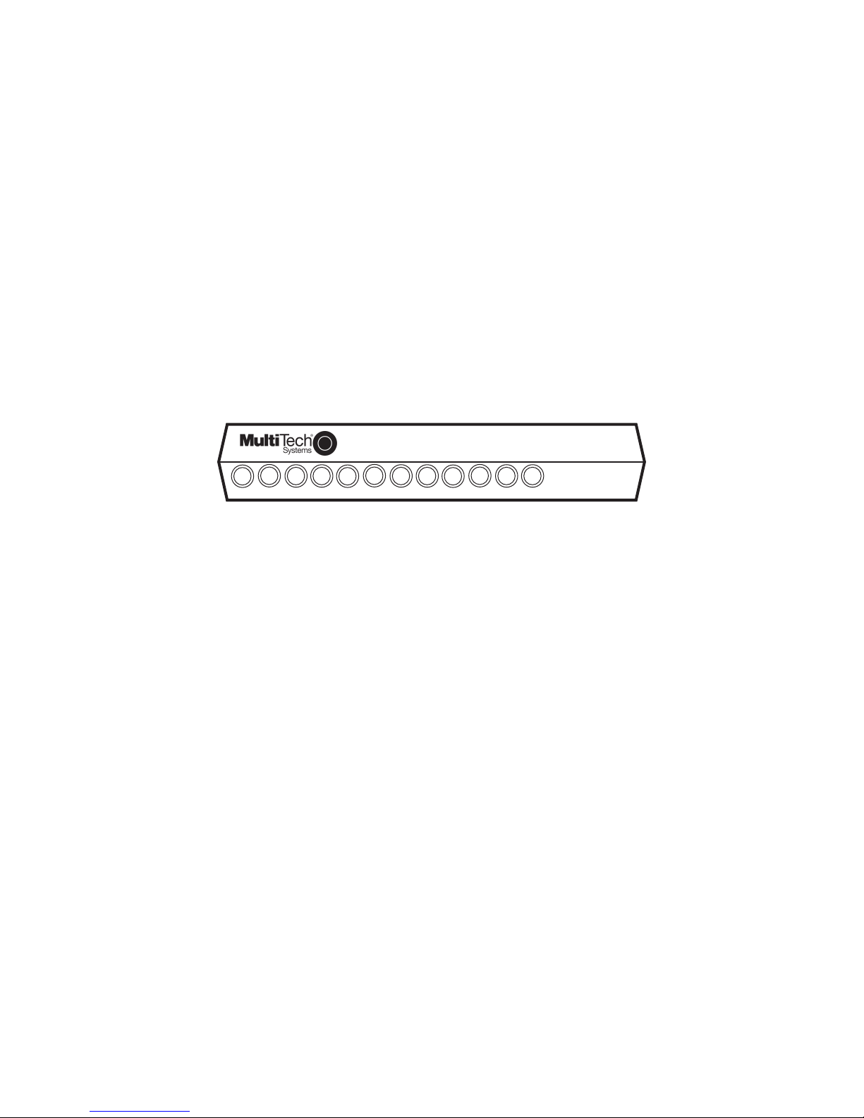
The front panel contains twelve LEDs each with a two- or three-letter overlay, and a one-word
legend below the LED describing its meaning. During normal operation the LEDs light (flash or
continuously lit) to indicate a defined condition. During test mode, the LEDs light during Test
Pattern test execution (refer to the Test Pattern section later in this chapter).
The front panel LEDs are shown below.
MultiDSU56K
SD
Send Rcv Carrier 56K 19.2K 9600 4800 Clear Request NoSgnl Outage Test
CD
RD
19.2
56
48
96
CTS
RTS
DOS
NS
TM
Multi-Rate DSU/CSU
Figure 4-1. MultiDSU56K Front Panel
4.2.1 SD Indicator
The SD (Transmit) LED lights to indicate the DTE is sending data (0 or a space) across the DTE
connector.
The SD LED should appear to flash during normal data transmission.
4.2.2 RD Indicator
The RD (Receive) LED lights when the MultiDSU56K receives data (a 0 or a space) from the
network.
The RD LED should appear to flash during norm al data rec ept ion .
4.2.3 CD Indicator
The CD (Carrier Detect) LED lights when the MultiDSU56K has received the data carrier from the
network. This indicator will go off when the MultiDSU56K is receiving the idle code or no signal at
all. If RTS is off on the remote DSU, the remote DSU sends an idle code to the local DSU.
4.2.4 56K Indicator
The 56K LED lights when the “Data Rate” selection is set at 56000 bps. This indicator will be off
for all other data rates. Refer to Chapter 2 for switch settings.
4.2.5 19.2 Indicator
The 19.2 LED lights when the “Data Rate” selection is set at 19200 bps. This indicator will be off
for all other data rates. Refer to Chapter 2 for switch settings.
82017502 19
Page 20

MT56DSU2 Owner’s Manual
4.2.6 96 Indicator
The 96 LED lights when the “Data Rate” selection is set at 9600 bps. This indicator will be off for
all other data rates. Refer to Chapter 2 for switch settings.
4.2.7 48 Indicator
The 48 LED lights when the “Data Rate” selection is set at 4800 bps. This indicator will be off for
all other data rates. Refer to Chapter 2 for switch settings.
4.2.8 CTS Indicator
The CTS (Clear to Send) LED lights when the MultiDSU56K generates a CTS in response to
either an RTS signal received at the DTE connector, or RTS forced on by the corresponding DIP
switch. If the Circuit Assurance option is enabled, the CTS will be off whenever Carrier Detect is
off.
4.2.9 RTS Indicator
The RTS LED lights when the RTS signal is received from the DTE. The DIP switch for RTS
Forced On does not affect this indicator. Refer to Chapter 2 for switch settings.
4.2.10 NS Indicator
The NS (No Signal) LED lights when no signal at all is received from the network, or when the
signal is too weak for normal MultiDSU56K operation. This indicator will also flash to indicate that
errors have been detected when using the Test Pattern diagnostic feature.
4.2.11 OOS Indicator
The OOS (Outage) LED lights when an outage condition exists. This occurs when there is a
failure in the digital service detected by the network, and the telco sends a repetitive OOS
sequence.
If this indicator is on, check the remote DSU for proper installation and operation. If the remote
DSU is installed and operating corr e ctl y, then report the O ut-O f- Ser vi ce co ndi tio n to the
telephone company.
4.2.12 TM Indicator
The TM (Test Mode) LED lights when one of the Test switches is set to the down (Test enabled)
position. When the TM LED is lit, normal operation (network transmit/receive) cannot occur. Refer
to the “Diagnostic” Tests section for more information.
4.3 Diagnostic Tests
The MultiDSU56K is set to a default of Normal (non-diagnostic) mode at the factory. When
diagnostics are to be run, change the DIP switches as described in Chapter 2 of this manual.
When a failure occurs in the digital facility (telco equipment), the network will detect the failure
and send a repetitive OOS signal sequence to your equipment. Your equipment can detect local
loop failure by the absence or distortion of the digital signal. If an OOS is received when data is
expected, check the remote (far-end) transmitting equipment. If the remote equipment is
transmitting properly, contact your telephone company. If the telco is required to perform remote
tests, the channel will be tempor ar ily interrupted and loss of data may oc cur.
The following sections describe the tests that are available for the MultiDSU56K.
82017502 20
Page 21
MT56DSU2 Owner’s Manual
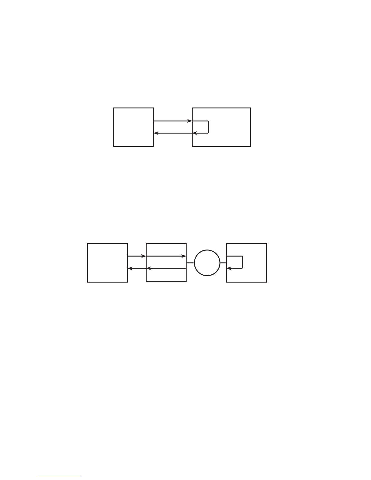
4.3.1 Local Loopback Test
This test allows you to test the local DTE and the local MultiDSU56K. Use the following steps to
perform the Local Loopback Test.
1. Set DIP switch #9 to the down position.
2. The front panel Test (TM) LED lights, and if you send data from your DTE, it should be “looped
back” to your DTE. If you have access to a Bit Error Rate Tester, this can be used in place of
the DTE.
DTE
(Or BERT Tester)
(In Local Loopback Test Mode)
MultiDSU56K
4.3.2 Digital Loopback Test
This test allows you to test the local DTE, the local MultiDSU56K, the communications link, and
the remote MultiDSU56K. Use the following steps to perform the Digital Loopback Test.
1. Set DIP switch #9 on the remote MultiDSU56K to the down position.
2. The front panel Test (TM) LED lights, and if you send data from the local DTE, it should be
looped back to the local DTE. If you have access to a Bit Error Rate Tester, this can be used in
place of the local DTE.
Network
Local DTE
(or BERT Tester)
Local
MultiDSU56K
Remote MultiDSU56K
(In Digital Loopback Test Mode)
82017502 21
Page 22
MT56DSU2 Owner’s Manual
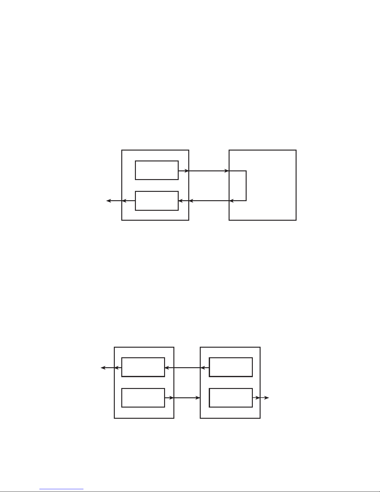
4.3.3 Digital Loopback Test With Test Pattern Test
This test allows you to test the local MultiDSU56K, the communications link, and the remote
MultiDSU56K. Use the following steps to perform the Digital Loopback Test with the Pattern Test.
With this test enabled, the MultiDSU56K sends and detects a pre-defined 15-bit pseudo-random
test pattern. When an error is detected by the MultiDSU56K, the NS (No Signal) LED flashes.
1. Set DIP switch #9 on the remote MultiDSU56K to the down position.
2. Set DIP switch #10 on the local MultiDSU56K to the down position.
3. The test pattern is generated and either detected as a good test pattern (test patterns match)
or as a failed test (test pattern received does not match the pattern sent).
Test Pattern
Generator
No Signal
(NS)
LED
Test Pattern
Detector
Local MultiDSU56K
(In Test Pattern Mode)
Remote MultiDSU56K
(In Digital Loopback Mode)
4.3.4 Test Pattern Test
This test allows you to test the local MultiDSU56K, the communications link, and the remote
MultiDSU56K.
With this test enabled, the MultiDSU56K sends and detects a pre-defined 15-bit pseudo-random
test pattern. When an error is detected by the MultiDSU56K, the NS (No Signal) LED flashes. To
enable the Test Pattern Test, perform the following.
1. Set DIP switch #10 on both the local and the remote MultiDSU56K to the down position.
2. The test pattern is generated and either detected as a good test pattern (test patterns match)
or as a failed test (test pattern received does not match the pattern sent).
No Signal
(NS)
LED
Test Pattern
Detector
Test Pattern
Generator
Local MultiDSU56K
(in Test Pattern mode)
82017502 22
Test Pattern
Generator
(Network)
Test Pattern
Detector
Remote MultiDSU56K
(in Test Pattern mode)
No Signal
(NS)
LED
Page 23
MT56DSU2 Owner’s Manual
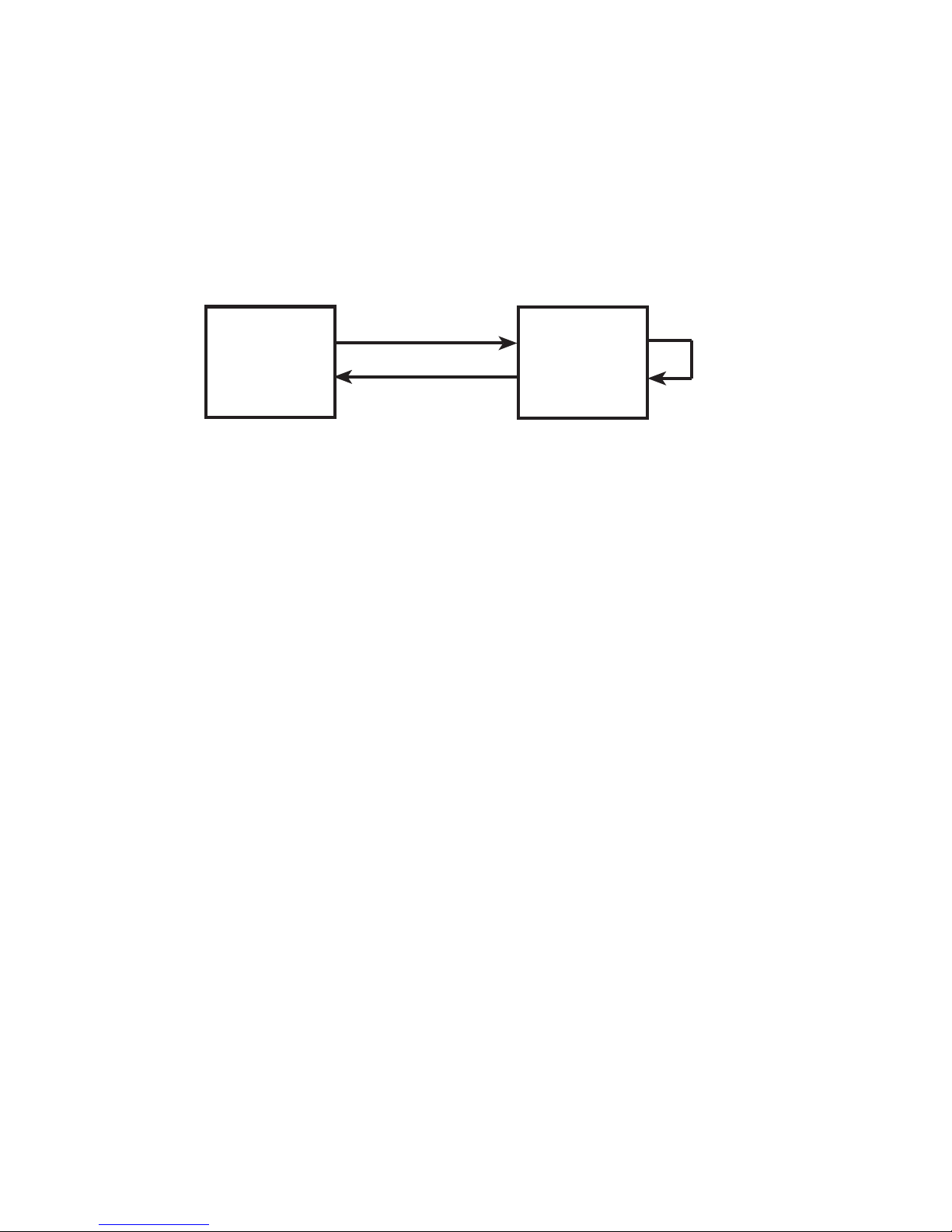
4.3.5 DSU Loopback Test
This test lets you verify proper DSU operation by matching a transmitted signal to the “looped-
back” receive signal. Refer to Appendix B for cable description.
1. Obtain a DSU Loopback cable (#45640100) from Multi-Tech, or assemble one. Refer to
Appendix B for instructions on building the Loopback cable.
2. Plug the Loopback cable into the back panel LINE jack.
3. If you send data from your DTE, it should be “looped back” to your DTE. If you have access to
a Bit Error Rate Tester, this can be used in place of the DTE.
Loopback
Cable
DTE
DSU
being tested
82017502 23
Page 24
MT56DSU2 Owner’s Manual
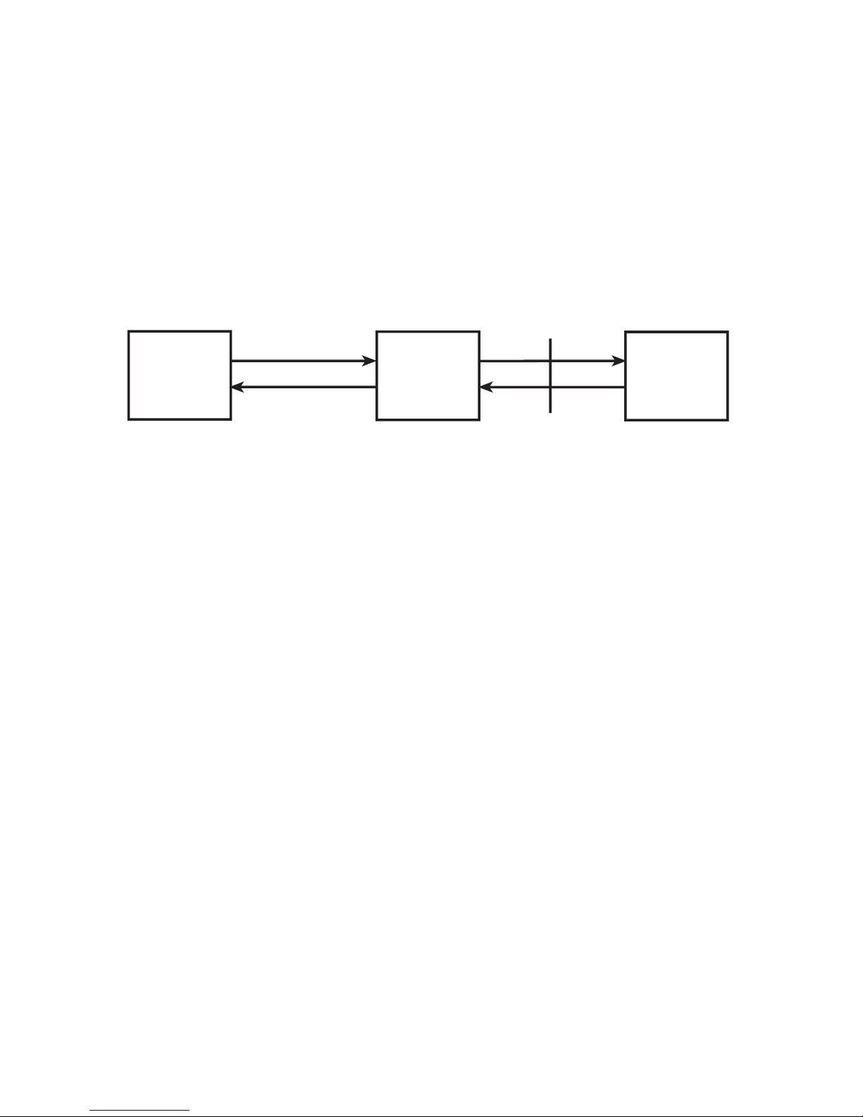
4.3.6 DSU Back-to-Back Test
This test lets you connect two DSUs with a bac k-to- b ack cab le to veri fy pr oper DSU operation.
Using a DSU that is known to be operational, you can test a second DSU that is suspect.
1. Obtain a DSU Back-to-Back cable (#45050000) from Multi-Tech, or assemble one. Refer to
Appendix B for instructions on building the Back-to-Back cable.
2. Plug the cable into each DSU’s LINE jack.
3. On the “good” DSU, set DIP switch #9 to the down position.
4. Set one DSU to internal clocking and the other DSU to DDS clocking.
5. If you send data from your DTE, it should be “looped back” to your DTE. If you have access to
a Bit Error Rate Tester, this can be used in place of the DTE.
DTE
“Suspect”
DSU
Back-to-Back
Cable
“Good” DSU in
Loopback Mode
82017502 24
Page 25

MT56DSU2 Owner’s Manual
Chapter 5 – Service, Warranty and Tech Support
Limited Warranty
Multi-Tech Systems, Inc. (icMTSl,) warrants that its products will be free from defects in material or
workmanship for a period of two years from the date of purchase, or if proof of purchase is not provided,
two years from date of shipment. MTS MAKES NO OTHER WARRANTY, EXPRESSED OR IMPLIED,
AND ALL IMPLIED WARRANTIES OF MERCHANTABILITY AND FITNESS FOR A PARTICULAR
PURPOSE ARE HEREBY DISCLAIMED. This warranty does not apply to any products which have been
damaged b y lightning storms, water, or power surges or which have been neglected, altered, abused , used
for a purpose other than the one for which they were manufactured, repaired by the customer or any party
witho u t MTS™s written authorization, or used in any manner inconsistent with MTS™s instructions.
MTS™s entire obligation under this warranty shall be limited (at MTS™s option) to repair or replacement
of any products which prove to be defective within the warranty period, or, at MTS™s option, issuance of a
refund of the purchase price. Defective products must
be returned by Customer to MTS™s factory transportation prepaid.
MTS WILL NOT BE LIABLE FOR CONSEQUENTIAL DAMAGES AND UNDER NO
IRCUMSTANCES WILL ITS LIABILITY EXCEED THE PURCHASE PRICE FOR DEFECTIVE
PRODUCTS.
On-line Warranty Registration
To register your DSU on-line, go to: http://www.multitech.com/register
Tech Support
Multi-Tech has an excellent staff of technical support personnel available to help you get the most out of
your Multi-Tech product. If you have any questions about the operation of this unit, call 1-800-972-2439.
Please fill out the modem information (below), and have it available when you call. If your DSU requires
service, the tech support specialist will guide you on how to send in your DSU.
4.2.1 Recording Product Information
Please fill in the following information on your Multi-Tech product. This will help Tech Support in
answering your questions.
Model No.: ____________________________________
Serial No.: ______________________________________
The model and serial numbers are silkscreened on the bottom of your DSU.
Please note the status of your DSU before calling tech support. This status can include LED indicators,
screen messages, diagnostic test results, problems with a specific application, etc.
Service
If your tech support specialist decides that service is required, DSUs may be sent (freight prepaid) to our
factory. Return shipping charges will be paid b y Multi -Tech Systems (within North America).
Include the foll o wi ng wi th yo ur mod e m:
• a description of the problem.
• return billing and return shipping addresses.
• contact name and phone number.
• check or purchase order number for payment if the modem is out of warranty. (The standard repair
charge for this modem is $95. This price is valid at the time of this publication but could change in the
future. Check with your technical support specialist.)
• if possible, note the name of the technical support specialist with whom you spoke.
82017502 25
Page 26

MT56DSU2 Owner’s Manual
If you need to inquire about the status of the returned product, be prepared to provide the serial number of
the product sent .
Send DSUs to:
MULTI-TECH SYSTEMS, INC.
2205 WOODALE DRIVE
MOUNDS VIEW, MINNESOTA 55112
ATTN: SERVICE OR REPAIRS
82017502 26
Page 27
MT56DSU2 Owner’s Manual
Appendix A - Application Examples
INTRODUCTION
This section illustrates several types of app lications in which the MultiDSU56K is typically used .
These types include:
• DDS point-to-point application,
• DDS multipoint (polled) application,
• Local Area Data Set,
• External Clocking application, and
• Analog Off-Net Extension application
DDS POINT-TO-POINT APPLICATION
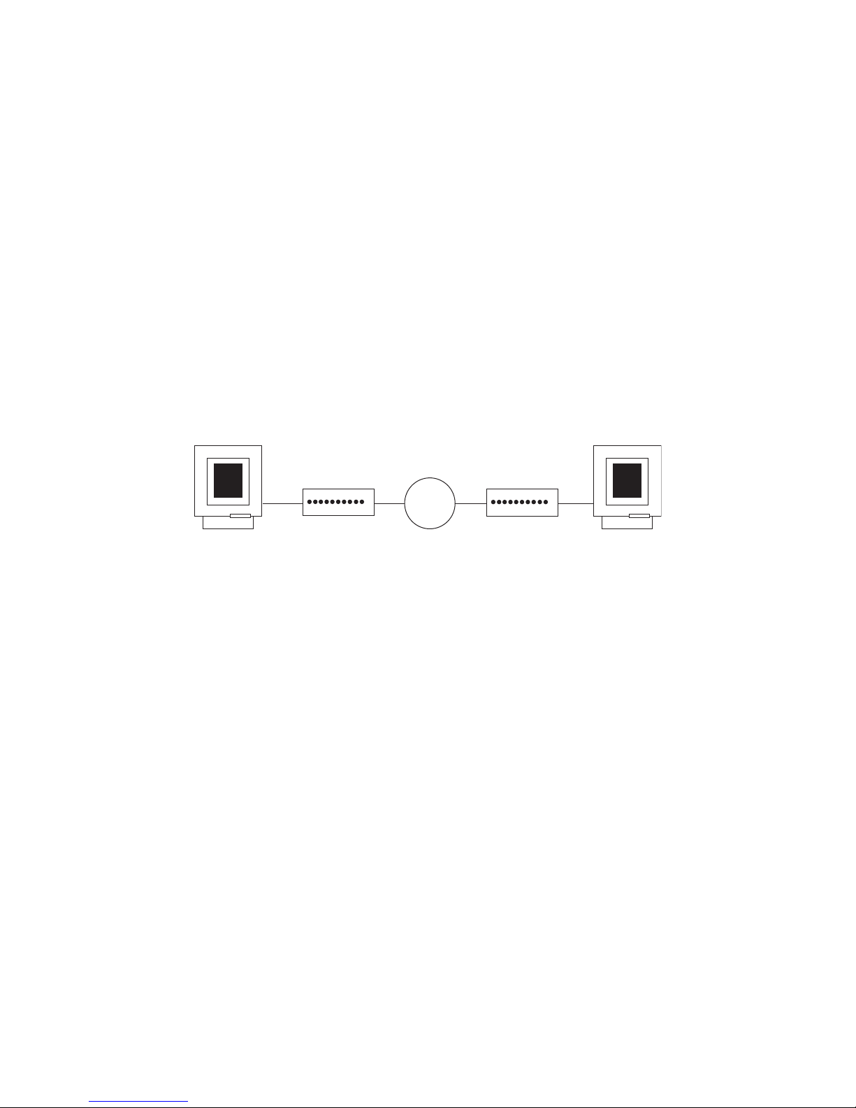
In this application, the MultiDSU56K provides the interface between the DDS line and the DTE at your
site. Your network provider will provide (at your request) a DDS line connecting the desired locations.
The figure below depicts a sample DDS Point-to-point application.
DTE
DDS
Network
MultiDSU56K
MultiDSU56K
Figure A-1. DDS Point-to-Point Application
DTE
82017502 27
Page 28
MT56DSU2 Owner’s Manual
DDS MULTIPOINT (POLLED) APPLICATION
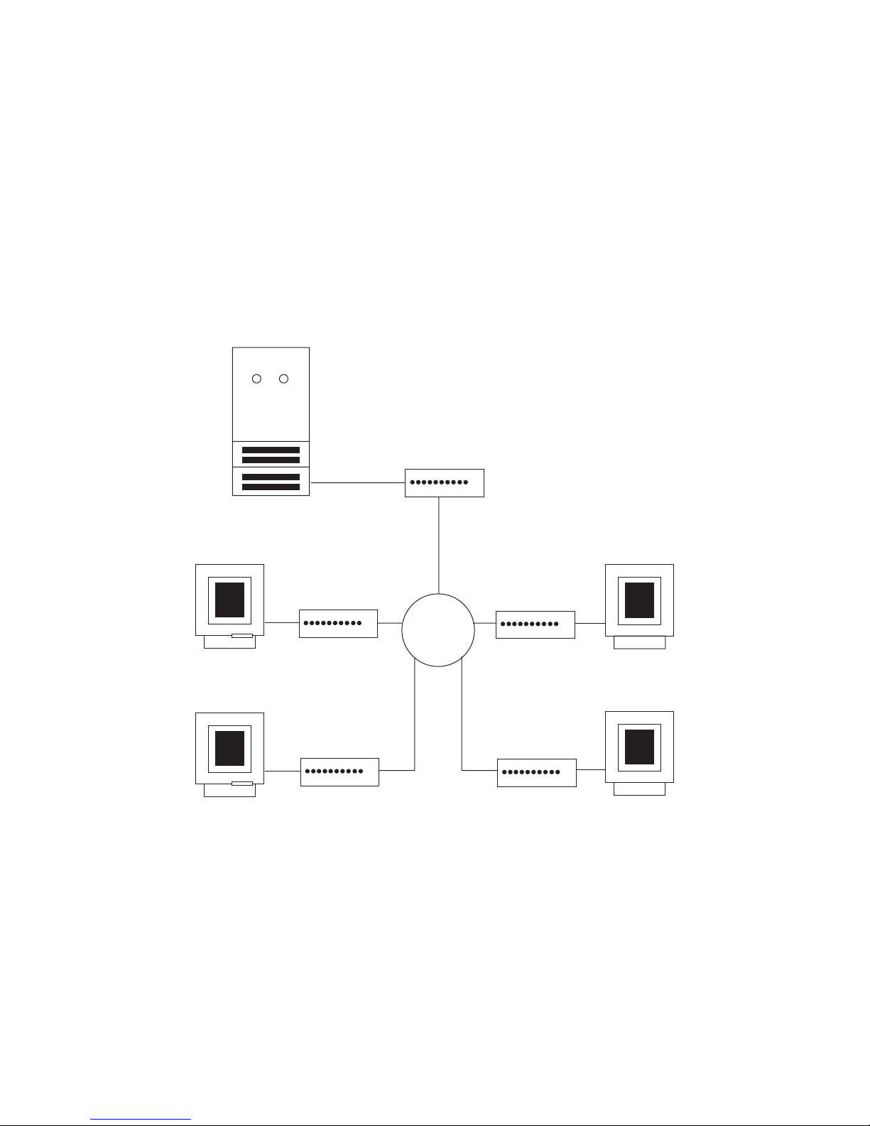
Since your Central Office (CO) equipment must include “Multipoint Junction Units” (MJU5) and other
special arrangements for this type of service, you may need to coordinate efforts with your netwo rk service
provider.
The MultiDSU56K at the host end is the Master Station (also called the “Control Station”), which typically
has RTS forced on. The attached MultiDSU56Ks are called “remote stations” and have RTS controlled by
the DTE.
Multipoint DDS provides communication between a control station and two or more remote stations. All
data transmitted by the control station is sent to each remote station. For data transmitted from the remote
stations, the MJUs combine bit streams from the re mote statio ns into a single, serial bit stream sent to the
control station. All stations on the same multipoint circuit must run at the same bit rate (any of the DDS
customer service rates).
The figure below shows a typical Multipoint (Polled) application.
MultiDSU56K
(“Master Station”)
DTE
DTE
Host with
Database
Application
DDS Network
with
Multipoint
Equipment
MultiDSU56K
(“Remote Station”)
MultiDSU56K
(“Remote Station”)
MultiDSU56K
(“Remote Station”)
MultiDSU56K
(“Remote Station”)
Figure A-2. DDS Multipoint Polled Application
DTE
DTE
82017502 28
Page 29
MT56DSU2 Owner’s Manual
LOCAL AREA DATA SET APPLICATION
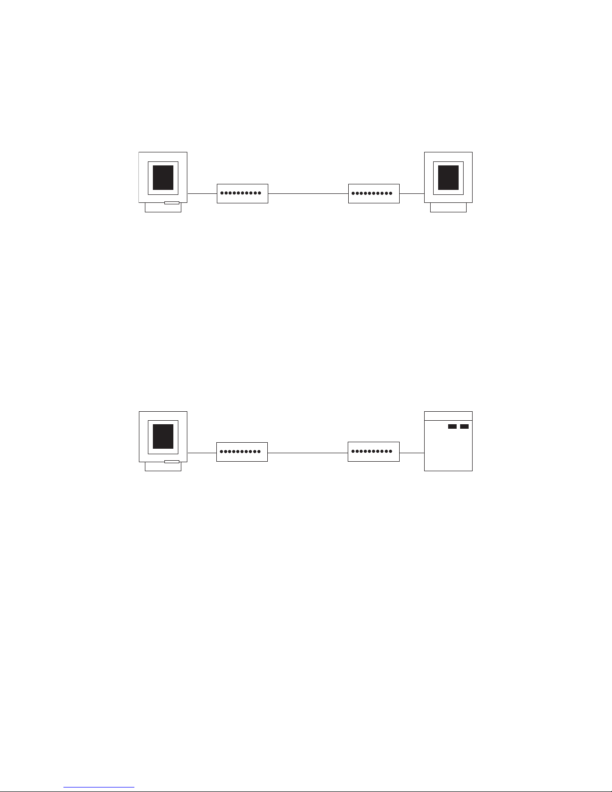
In this application, two pairs of wires provide the connection between two MultiDSU56K devices. The two
pairs can be up to the equivalent of 3 miles of 26 AWG wire at 56000 bps, or longer for subrate
applications (see distances chart in section 3.4.1 of this manual).
The figure below depicts a typical Local Area Data Set application.
Up to 3 miles
of 26 AWG wire
@ 56000 bps
DTE
MultiDSU56K
(Requires two pairs
of interconnection wires)
MultiDSU56K
DTE
Figure A-3. Local Area Data Set Application
EXTERNAL CLOCKING APPLICATION
This application is similar to the Local Area Data Set application e xcept for the ti ming option setting.
In the example below, the DTE connector of the T1 mux is connected to the DTE connector of the
MultiDSU56K. Here, the MultiDSU56K must receive timing information from the T1 mux.
The MultiDSU56K is set for external timing in this type of application. At the DTE end, DDS timing is
selected, providing normal clocking to the DTE.
The figure below shows a typical External Clocking application.
4-Wire Line
DTE
MultiDSU56K
(with DDS timing)
MulitDSU56K
(with external timing)
T1
Multiplexer
82017502 29
Figure A-4. External Clocking Application
Page 30
MT56DSU2 Owner’s Manual
ANALOG OFF-NET EXTENSION APPLICATION
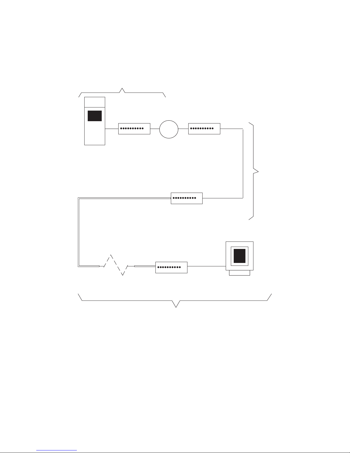
In this application, the MultiDSU56K is used with conventional analog mode ms a nd lines to complete DDS
circuits in an area where DDS is not available (Site #3 in the example below) or where the customer
requires an extension of the DDS circuit for a special application.
Site #1
DDS
Network
MultiDSU56K
(elastic store)
Site
#2
Front End
Processor (FEP)
MultiDSU56K
Modem
(external timing)
Analog
Line
Modem
(slave timing)
Site #3
Terminal
Figure A-5. Analog Off-Net Extension Application
82017502 30
Page 31

MT56DSU2 Owner’s Manual
Appendix B - Interface Signals and Connector Pinouts
DDS RJ48 CONNECTOR
Pin 1
As viewed from the rear
DESCRIPTION
This connector ties the MultiDSU56K to the DDS Network. The RJ48 connector is keyed for
proper insertion of a keyed RJ48 plug.
PIN IDENTIFICATION
Pin 8
Key
Pin Description Destination
1 T ransmit Pair To Line
2 T ransm it pair To Line
3N/C
4N/C
5N/C
6N/C
7 Rec ei ve Pa ir From Line
8 Rec ei ve Pa ir From Line
82017502 31
Page 32

MT56DSU2 Owner’s Manual
RS232C DB25S CONNECTOR
13
12
11
10
9 — Test Voltage (+V)
8 — Carrier Detect (CD)
7 — Signal Ground (SG)
6 — Data Set Ready (DSR)
5 — Clear To Send (CTS)
4 — Request To Send (RTS)
3 — Received Data (RD)
2 — Transmit Data (SD)
1
Transmitter Signal —
Element Timing
Receive Clock (RC) —
Transmit Clock (TC) —
As viewed from the rear
25
24
23
22
21
20
19
18
17
16
15
14
DESCRIPTION
This connector ties the MultiDSU56K to the DTE. The DB25S connector has the following pinout
configuration.
PIN IDENTIFICATION
Pin Description Signal
2 Transmit Data SD
3 Received Data RD
4 Request To Send RTS
5 Clear To Send CTS
6 Data Set Rea dy DSR
7 Signal Ground SG
8 Carrier Detect CD
9Test Voltage+V
15 Transmit Clock TC
17 Receive Clock RC
24 DTE Transmitter Signal Element Timing
82017502 32
Page 33
MT56DSU2 Owner’s Manual
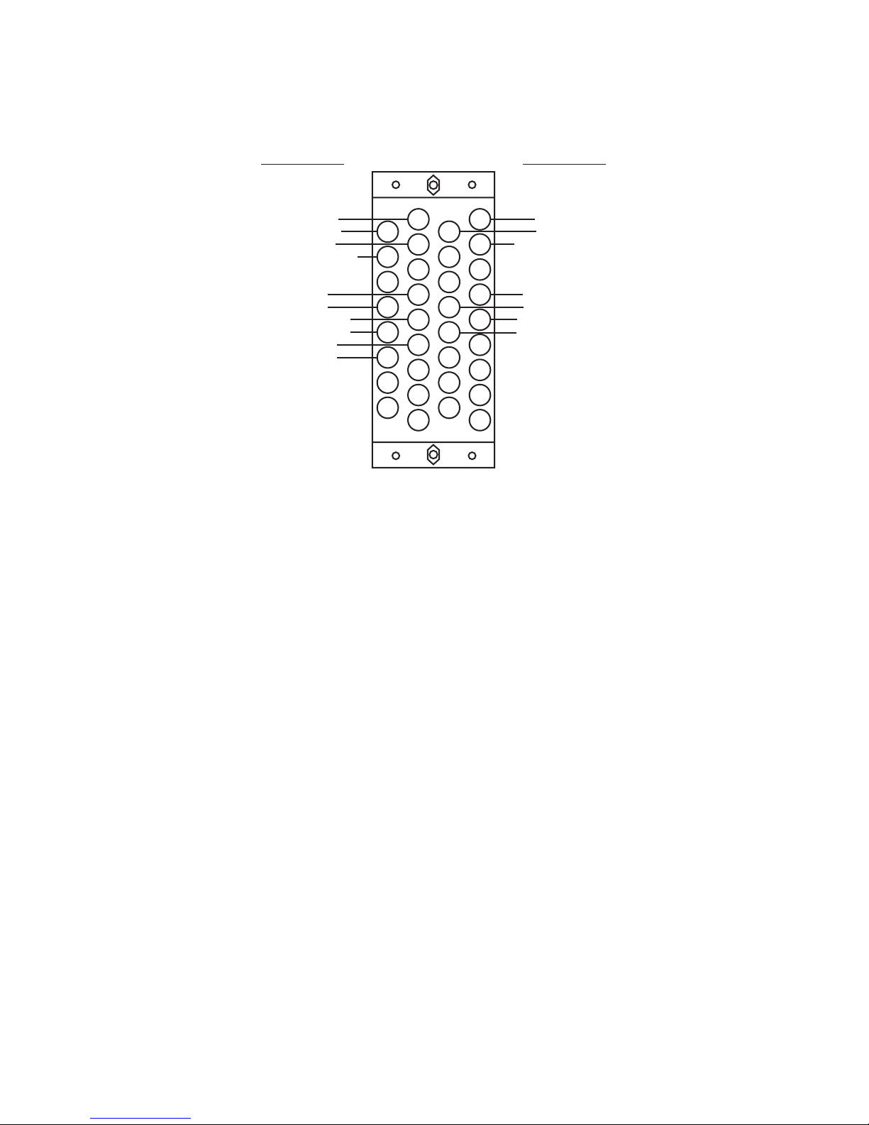
V.35 34-PIN CONNECTOR
Signal Designation Signal Designation
V.35 34-PIN CONNECTOR
Chassis Ground
Request To Send
Data Set Ready
Data Terminal Ready
Send Data (A)
Send Data (B)
Terminal T iming (A)
Terminal T iming (B)
Send Timing (A)
Send Timing (B)
A
E
K
P
U
Y
CC
HH
MM
D
J
N
T
X
BB
FF
LL
NN
C
H
M
S
W
AA
EE
KK
As viewed from the connector side
B
F
L
R
V
Z
DD
JJ
Signal Ground
Clear To Send
Data Carrier Detect
Receive Data (A)
Receive Data (B)
Receive Timing (A)
Receive Timing (B)
DESCRIPTION
This connector ties the MultiDSU56K to the DTE. The V.35 connector has the following pinout
configuration.
PIN IDENTIFICATION
Pin Description
A Chassis Ground
B Signal Ground
C Request To Send
D Clear To Send
E Data Set Ready
F Receive Line Signal Detect
H Data Terminal Ready
P Transmitted Data (A)
S Transmitted Data (B)
R Received Data (A)
T Received Data (B)
Y Transmit Clock (A)
AA Transmit Clock (B)
V Receive Clock (A)
X Receive Clock (B)
U External Transmit Clock (A)
W External Transmit Clock (B)
82017502 33
Page 34
MT56DSU2 Owner’s Manual
LOOPBACK CABLE
(MTS P/N 45640100)
1
8
DESCRIPTION
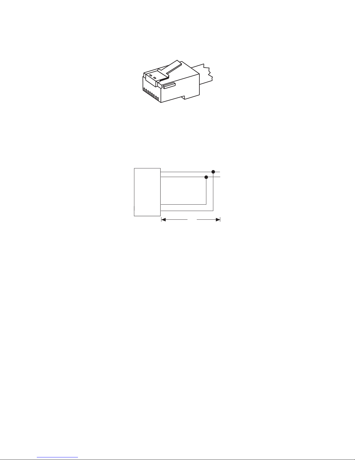
This cable lets you test the MultiDSU56K when a second DSU is not available. It tests the DSU
by having the DSU generate a signal, then the cable “loops” the signal back to the DSU for
comparison to the original signal sent. You can order this cable (#45640100) from Multi-Tech, or
build one using the instructions below. Refer to Chapter 4 for test procedures.
SCHEMATIC
TRANSMIT
1
TRANSMIT
2
3
4
RJ48S
5
6
RECEIVE
7
RECEIVE
8
6"
BUILD INSTRUCTIONS
1. Strip cable insulation 3/4"
2. Cut wires 3, 4, 5, 6 off.
3. Strip wires 1, 2, 7, 8 1/4"
4. Solder wires 1 and 8 together.
5. Solder wires 2 and 7 together.
6. Cover solder connections with 1" of shrink tube.
82017502 34
Page 35

MT56DSU2 Owner’s Manual
BACK-TO-BACK CABLE
(MTS P/N 45050000)
1
8
DESCRIPTION
This cable lets you test a suspect DSU by connecting it to a known good DSU. It tests the
suspect DSU by connecting its Transmit signal to the good DSUs Receive circuits. You can order
it from Multi-Tech (# 45050000), or build one using the instructions below. Refer to Chapter 4 for
test procedures.
SCHEMATIC
8
7
6
5
4
3
2
1
RJ48S
RJ48S
1
2
3
4
5
6
7
8
7"
BUILD INSTRUCTIONS
1. Strip cable installation 3/4".
2. Strip wires 1,2,7 and 8 on one end of cable and 8,7,2 and 1 on other end 1/4".
3. Cut unstripped wires off.
4. Solder wire 1 on one connector to 8 on the other.
5. Solder wire 2 on one connector to 7 on the other.
6. Solder wire 7 on one connector to 2 on the other.
7. Solder wire 8 on one connector to 1 on the other.
8. Cover solder connections with 1" of shrink tube.
82017502 35
Page 36

MT56DSU2 Owner’s Manual
Glossary
This section defines several of the terms used in this manual. For an overview of DSU basics, refer to
section 1.4 of this manual.
A
ALBO (Automatic Line Build Out) — part of the “equalizer” circuitry used to compensate for various
gauges and alterations of local loops.
Anti-Streaming — an option that prevents a streaming (jammed) DTE from affecting other devices on a
multi-poi nt ne t wor k.
asynchronous communic ations — communications between computer devices at irregular intervals. To do
so, the device adds start and stop bits to each character it sends.
B
BERT (bit error rate tester) — the type of testing used to verify the operating par ameters of a data
communications line.
bps (bits per second) — unit of measure for data transmission.
C
Central Office (CO) — the telephone company site where switching equipment is located (as opposed to
customer premises).
channel — the digital path on a cable on which data is transmitted. A logical way to look at the path data
travels when sent between
locations.
circuit assurance — an optional conditioning of the CTS signal.
Clear To Send (CTS) — an interface signal that indicates whether the modem or DSU is ready to accept a
data transmission from the DTE.
CO (Central Office) — facility where communications common carriers terminate customer lines and
locate line interconnection equipment.
clocking — a synchronous device circuit that sends signals at a precise frequency corresponding to the bit
rate of that device.
control station — the station on a DDS multipoint circuit that is nearest the host system and transmits data
to each remote station and receives a single serial bit stream from the remote stations via the MJU.
crossover cable — a cable with a conductor that runs the length of the cable, but connects to a different pin
number at each end (connects pins 2103 and 3 to 2 from DTE to DSU/CSU).
CSU (Channel Service Unit) — a device used to terminate a digital circuit (such as DDS or T1) at the
customer site. Used in combination with a “DSU”.
82017502 36
Page 37

MT56DSU2 Owner’s Manual
D
Data Communications Equipment (DCE) — equipment that provides the function to establish, maintain
and terminate a connection. Additionally, provides the signal convers ion required for communications
between DTE and data circuit or telephone line. See also “DTE”.
DDS (Dataphone Digital Service) — AT&Ts private-line end-to-end digital service, with data r ates
(typically) at 2400, 4800, 9600, 19200, and 56000 bps. Now an AT&T “Accunet” family offering. The
DDS is a synchronous network that uses the ABAT S test system, which requires little manual intervention.
default — the factory set position or value that a device assumes at startup. An alterab le p a r ameter.
digital loopback — a type of diagnostic test where the transmitted signal is returned to the sending device
after passing through a data communications link; the returned signal is then compared to the transmitted
signal.
DSR (data set ready) — an RS232 signal that indicates the DCE and line are ready to receive data.
DSU (Data Service Unit) — a device used to interface a user’s DSU to a digital circuit (such as DDS or
Ti). Used in combination with a “CSU’.
Data Terminal Equipment (DTE) —a device that provides output data in the form of digital signals. See
also “DCE”.
E
elastic store — an option that causes the DSU to allow for timing phase drifts in non-DDS applications.
F
four-wire circuit — two twisted-pair circuits with each pair transmitting signals in the opposite direction.
J
jumper — a wire that connects two or more pins; a configurable component on a printed circuit board.
L
leased line — a permanent communication line between a computer and a terminal providing private,
continuous access to the connection by a subscriber for a fixed fee.
LED (Light Emitting Diode) — a light source that emits visible li ght.
local loopback — a type of diagnostic test where the transmitted signal is returned to the sending device
after passing through a local communications loop; the returned signal is then compared to the transmitted
signal.
82017502 37
Page 38

MT56DSU2 Owner’s Manual
M
master station — see “control station”.
MJU (Multipoint Junction Unit) — a digital data bridge, located at telco office, for the DDS network. Used
to combine remote station’s bit streams into one serial bit stream for transmission to the control station.
Multi-drop — see “multipoint”.
multipoint — a single line or circuit that connects several stations supporting terminals located in different
areas. Usually requires some type of pooling method. Contrast “point-to-point”.
multipoint circuit — a type of DDS network that includes one control station, attached remote stations, and
all channel, MJU and digital access lines for station interconnection.
0
OCU (Office Channel unit) — a DSUICSU located in the telco central office.
OOS (Out Of Service) — a condition that occurs when a digital service failure is detected by the network.
p
point-to-point — a circuit with two point directly connected, with no intermediate nodes, computers or
branched circuits (but possibly switching facilities). A type of connectio n that lin ks two (and only two)
logical entities (e.g., a phone line circuit). Contrast “multipoint”.
R
remote station — a device on a multipoint DDS network that communicates with the master station via the
OCU. All remote stations on the DDS must operate at the same bit rate. ( AKA, “outlying station”.)
RJ (Registered Jack) — a connector for use at customer site (e.g., RJ11, RJ45, RJ48).
RTS (Request To Send) — a lead on the terminal interface. Also a communications device handshaking
signal; generated by the receiving device in order to condition a remote transmitter to begin data
transmission.
S
serial — a type of communications between two devices in whic h data is tr ansmitted one bit at a time.
subrate — a data transmission rate of less than or equal to 19.2K bps.
synchronous transmission — data communications where the transmitting and receiving devices are
synchronized and characters or bits are sent at a fixed rate.
system status — optional conditioning of the DSR signal.
82017502 38
Page 39

MT56DSU2 Owner’s Manual
T
test pattern — a diagnostic test for sending ,detecting and checking a pre-defined p a tter n of bits.
two-wire circuit — A circuit in which one channel (line) is used for communications in both directions.
Contrast ‘Iour-wire circuit”.
82017502 39
 Loading...