

Page 1
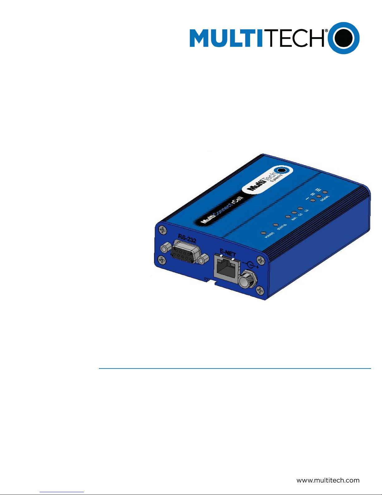
MultiConnect
MTR-H5 User Guide
®
rCell 100
Page 2
MULTICONNECT® RCELL 100 SERIES ROUTER USER GUIDE
MultiConnect®rCell 100 Series Router User Guide
Model: MTR-H5
Part Number: S000566 Version: 1.0.13
Copyright
This publication may not be reproduced, in whole or in part, without the specific and express prior written permission signed by an executive officer of
Multi-Tech Systems, Inc. All rights reserved. Copyright © 2014 by Multi-Tech Systems, Inc.
Multi-Tech Systems, Inc. makes no representations or warranties, whether express, implied or by estoppels, with respect to the content, information,
material and recommendations herein and specifically disclaims any implied warranties of merchantability, fitness for any particular purpose and noninfringement.
Multi-Tech Systems, Inc. reserves the right to revise this publication and to make changes from time to time in the content hereof without obligation of
Multi-Tech Systems, Inc. to notify any person or organization of such revisions or changes.
Legal Notices
The MultiTech products are not designed, manufactured or intended for use, and should not be used, or sold or re-sold for use, in connection with
applications requiring fail-safe performance or in applications where the failure of the products would reasonably be expected to result in personal injury or
death, significant property damage, or serious physical or environmental damage. Examples of such use include life support machines or other life
preserving medical devices or systems, air traffic control or aircraft navigation or communications systems, control equipment for nuclear facilities, or
missile, nuclear, biological or chemical weapons or other military applications (“Restricted Applications”). Use of the products in such Restricted
Applications is at the user’s sole risk and liability.
MULTITECH DOES NOT WARRANT THAT THE TRANSMISSION OF DATA BY A PRODUCT OVER A CELLULAR COMMUNICATIONS NETWORK WILL BE
UNINTERRUPTED, TIMELY, SECURE OR ERROR FREE, NOR DOES MULTI-TECH WARRANT ANY CONNECTION OR ACCESSIBILITY TO ANY CELLULAR
COMMUNICATIONS NETWORK. MULTITECH WILL HAVE NO LIABILITY FOR ANY LOSSES, DAMAGES, OBLIGATIONS, PENALTIES, DEFICIENCIES, LIABILITIES,
COSTS OR EXPENSES (INCLUDING WITHOUT LIMITATION REASONABLE ATTORNEYS FEES) RELATED TO TEMPORARY INABILITY TO ACCESS A CELLULAR
COMMUNICATIONS NETWORK USING THE PRODUCTS.
Contacting MultiTech
Knowledge Base
The Knowledge Base provides immediate access to support information and resolutions for all MultiTech products. Visit http://www.multitech.com/kb.go.
Support Portal
To create an account and submit a support case directly to our technical support team, visit: https://support.multitech.com.
Support
Business Hours: M-F, 8am to 5pm CT
Country By Email By Phone
Europe, Middle East, Africa: support@multitech.co.uk +(44) 118 959 7774
U.S., Canada, all others: support@multitech.com (800) 972-2439 or (763) 717-5863
Warranty
To read the warranty statement for your product, visit www.multitech.com/warranty.go. For other warranty options, visit www.multitech.com/es.go.
World Headquarters
Multi-Tech Systems, Inc.
2205 Woodale Drive, Mounds View, MN 55112
Phone: (800) 328-9717 or (763) 785-3500
Fax (763) 785-9874
2 MultiConnect®rCell 100 MTR-H5 User Guide
Page 3

CONTENTS
Contents
Product Overview .................................................................................................................................................... 5
About MultiConnect rCell 100 Series Router................................................................................................................ 5
Documentation ........................................................................................................................................................... 5
Product Build Options ................................................................................................................................................... 6
Descriptions of LEDs...................................................................................................................................................... 7
Side Panels .................................................................................................................................................................... 8
Ethernet LED Descriptions ........................................................................................................................................... 9
Specifications ................................................................................................................................................................ 9
Dimensions.................................................................................................................................................................. 11
Label locations ............................................................................................................................................................ 11
Power Draw ................................................................................................................................................................ 13
RF Specifications ......................................................................................................................................................... 13
Safety Warnings..................................................................................................................................................... 14
Lithium Battery ........................................................................................................................................................... 14
ITE Equipment Ordinary Locations (US, Canada, and Europe) ................................................................................. 14
Class I, Division 2, Groups A, B, C, and D Hazardous Locations (US and Canada) .................................................... 14
ATEX (Europe only) ................................................................................................................................................... 15
Hazardous Location Special Considerations ............................................................................................................. 15
Ethernet Ports ............................................................................................................................................................. 15
Radio Frequency (RF) Safety ....................................................................................................................................... 15
Interference with Pacemakers and Other Medical Devices ...................................................................................... 16
Potential interference............................................................................................................................................... 16
Precautions for pacemaker wearers ........................................................................................................................ 16
Notice regarding Compliance with FCC and Industry Canada Requirements for RF Exposure .................................. 16
Cellular Information............................................................................................................................................... 18
Antenna System Cellular Devices................................................................................................................................ 18
HEPTA Antenna Information....................................................................................................................................... 18
Authorized Antenna/Antenna Specifications for Cellular Bands .............................................................................. 18
3G Antenna Requirements/Specifications ............................................................................................................... 18
GPS Antennas.............................................................................................................................................................. 19
GPS Antenna Specifications ...................................................................................................................................... 19
Bluetooth and Wi-Fi Antennas ................................................................................................................................... 19
Multi-Tech Ordering Information ............................................................................................................................. 19
Antenna Specifications.............................................................................................................................................. 19
Installing and Using the Router .............................................................................................................................. 20
Installing the Router.................................................................................................................................................... 20
Using Diversity .......................................................................................................................................................... 20
MultiConnect®rCell 100 MTR-H5 User Guide 3
Page 4

CONTENTS
Mounting the Device................................................................................................................................................... 21
Activating the Account for Wireless Devices ............................................................................................................. 21
Installing the SIM Card ............................................................................................................................................... 21
Setting up Wi-Fi........................................................................................................................................................... 22
Resetting the Device ................................................................................................................................................... 22
Resetting the Device to Factory Defaults .................................................................................................................. 22
Notice for Devices that Use Aeris Radios.................................................................................................................... 23
Regulatory Information.......................................................................................................................................... 24
47 CFR Part 15 Regulation Class B Devices ................................................................................................................. 24
Industry Canada Class B Notice................................................................................................................................... 24
FCC Interference Notice .............................................................................................................................................. 24
FCC and IC Antenna Requirements Toward License Exempt Radio Transmitters (Bluetooth/WLAN) ....................... 25
Requirements for Cellular Antennas with regard to FCC/IC Compliance ................................................................... 25
EMC, Safety, and R&TTE Directive Compliance ......................................................................................................... 25
Restriction of the Use of Hazardous Substances (RoHS) ............................................................................................ 26
REACH Statement ....................................................................................................................................................... 27
Registration of Substances........................................................................................................................................ 27
Substances of Very High Concern (SVHC) ................................................................................................................ 27
Waste Electrical and Electronic Equipment Statement .............................................................................................. 27
WEEE Directive.......................................................................................................................................................... 27
Instructions for Disposal of WEEE by Users in the European Union ........................................................................ 27
Information on HS/TS Substances According to Chinese Standards ......................................................................... 28
Information on HS/TS Substances According to Chinese Standards (in Chinese) ...................................................... 29
4 MultiConnect®rCell 100 MTR-H5 User Guide
Page 5

PRODUCT OVERVIEW
Product Overview
About MultiConnect rCell 100 Series Router
This guide describes the MultiConnect rCell 100 Series router. The rCell family of routers is carrier approved and
ready-to-deploy. You can use your device to provide secure data communication between many types of devices
that use legacy as well as the latest communication technologies. Some device models support:
■ Bluetooth communication to devices with this technology
■ Wi-Fi communication to devices with this technology
■ GPS
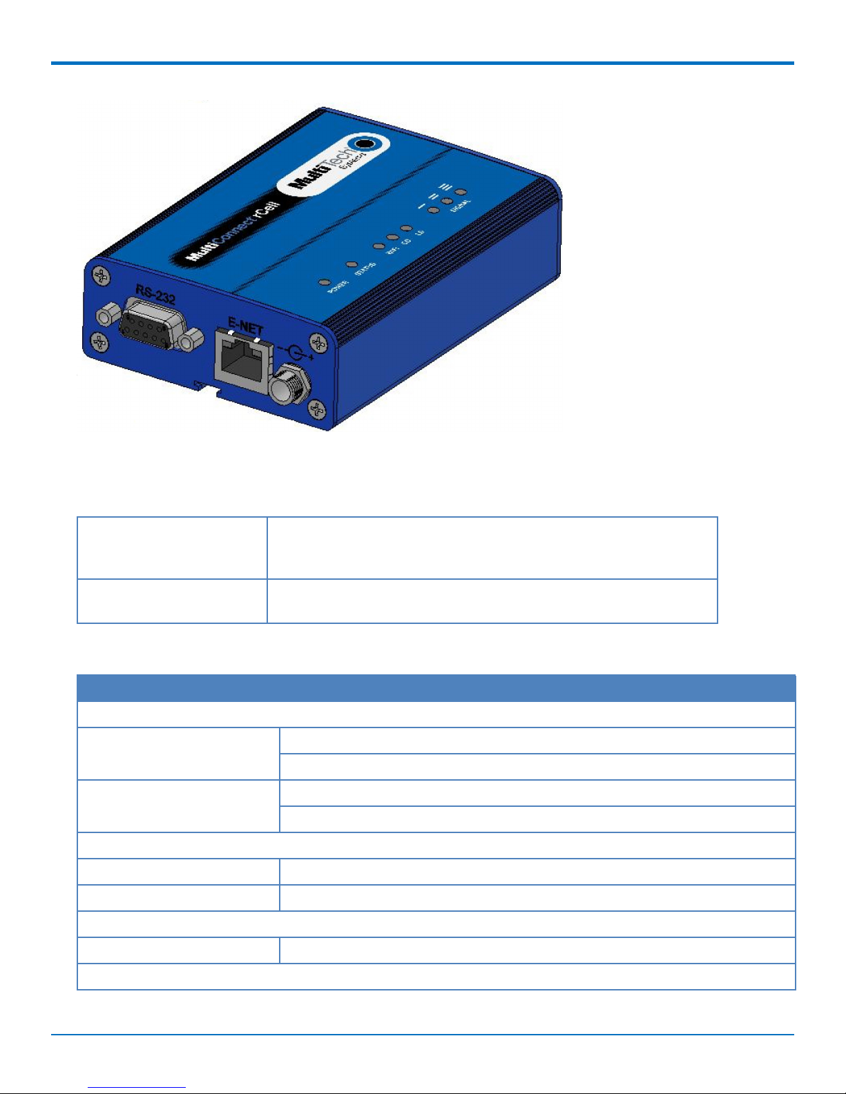
The router has an integrated cellular modem and includes 10/100 BaseT Ethernet and RS-232 serial connectivity.
An image of the device follows:
Items bundled with the MTR-H5-B10 device: 1 Taoglas GW.11.A153 Wi-Fi antenna, 2 Laird Hepta-SM MAF94300
antennas, 1 Trimble GPS antenna 66800-52 and 1 Globtek GT-41052-1509 9V 1.7A power supply.
Documentation
The following table describes additional documentation for your device. The documentation is available on the
Multi-Tech Installation Resources website at www.multitech.com/setup/product.go.
Document Description
User Guide This document. Provides an overview, safety and regulatory
API guide You can use the rCell API to manage configurations, poll statistics, and
MultiConnect®rCell 100 MTR-H5 User Guide 5
information, schematics and general device information.
issue commands. The design, patterns, and methods are documented
in the API Guide part number S000576.
Page 6
PRODUCT OVERVIEW
Document Description
AT Commands This document describes AT commands that are available for your
device. These commands are documented in the Reference Guide part
number S000574.
Product Build Options
Product Description
MTR-H5-B07 Supports HSPA+
MTR-H5-B08 Supports HSPA+ and GPS
MTR-H5-B09 Supports HSPA+, Wi-Fi, and Bluetooth
MTR-H5-B10 Supports HSPA+, Wi-Fi, Bluetooth, and GPS.
6 MultiConnect®rCell 100 MTR-H5 User Guide
Page 7
PRODUCT OVERVIEW
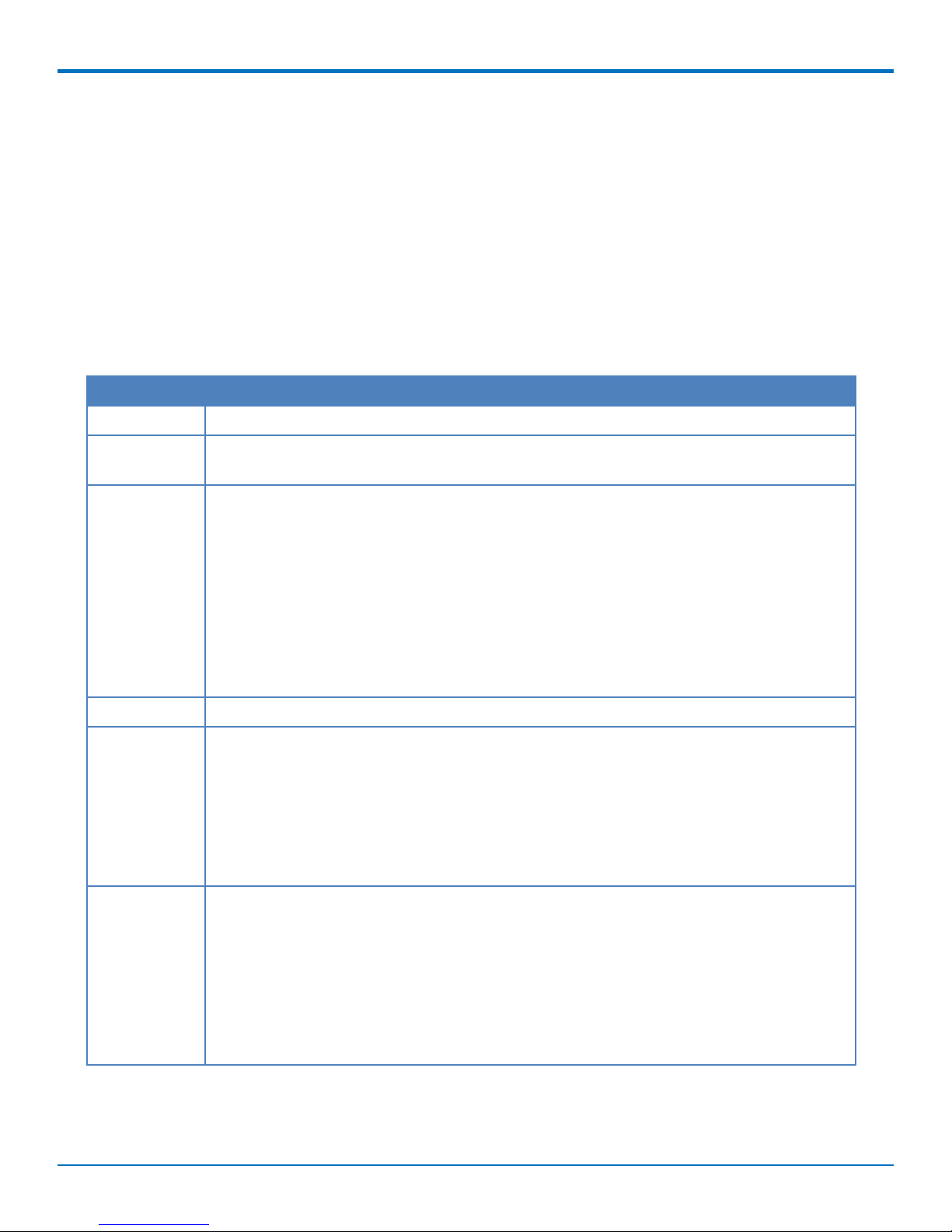
Descriptions of LEDs
The top panel contains the following LEDs:
■ Power and Status LEDs—The Power LED indicates that DC power is present and the Status LED blinks when
the unit is functioning normally.
■ Wi-Fi—Indicates if the device is serving as a Wi-Fi access point or acting as a Wi-Fi client. Not all models
support Wi-Fi.
■ Modem LEDs—Two modem LEDs indicate carrier detection and link status.
■ Signal LEDs—Three signal LEDs display the signal strength level of the wireless connection.
■ Ethernet LEDs—These LEDs are not on the top panel. See the section Ethernet LED Descriptions for
descriptions of these LEDs.
LED Indicators
POWER Indicates presence of DC power when lit.
STATUS The LED is a solid light when the device is booting up, saving the configuration, restarting,
or updating the firmware. When the Status LED begins to blink, the router is ready for use.
WiFi
CD Carrier Detect. When lit, indicates data connection has been established.
LS Link Status
SIGNAL Signal strength for cellular.
Infrastructure mode
■ The WiFi LED is lit when WiFi AP mode is enabled, unlit when disabled.
■ The LED flashes rapidly to indicate traffic.
Client mode:
■ The WiFi LED is lit when WiFi client mode is enabled.
■ The WiFi LED blinks slowly when associated with an Access Point.
■ The WiFi LED flashes rapidly to indicate traffic.
OFF—There is no power to the cellular radio.
Continuously Lit—Powered, connected and transmitting and receiving data.
Slow Blink (-0.2Hz) —Powered, connected and idle.
Faster Blink (-3Hz)— Powered and searching for a connection.
ALL OFF—Unit is off, not registered on network, or extremely weak signal (0 < = RSSI <
6).
1 Bar “ON”—Very weak signal (7 < = RSSI <14).
1 Bar and 2 Bar “ON”—Weak signal (15 < = RSSI <23).
1 Bar, 2 Bar, and 3 Bar “ON”—Good signal (24 <= RSSI > = 31).
MultiConnect®rCell 100 MTR-H5 User Guide 7
Page 8
PRODUCT OVERVIEW
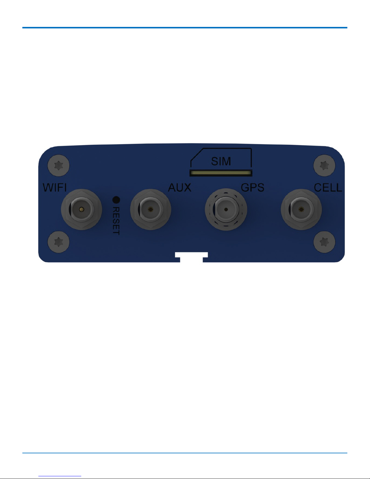
Side Panels
The device has connectors on either side. The figure that follows shows the side which has a SIM card holder, as
well as Wi-Fi, Auxiliary, GPS and cellular antenna connectors. It also has a reset button. Depending on the model of
your device, the following items may or may not appear:
■ Aux connector
■ GPS connector
■ Wi-Fi connector
■ SIM card slot.
A side panel of the device follows:
Not all models have a GPS connector.
The figure that follows shows the other side of the device.
8 MultiConnect®rCell 100 MTR-H5 User Guide
Page 9
PRODUCT OVERVIEW
Ethernet LED Descriptions
Two Ethernet LEDs are physically on the RJ-45 connector(s). The table that follows describes these LEDs.
Ethernet Link Right LED on Ethernet connector. Blinks when there is transmit and
receive activity on the Ethernet link. It shows a steady light when
there is a valid Ethernet connection.
Ethernet Speed Left LED on Ethernet connector. Lit when the Ethernet is linked at 100
Mbps. If it is not lit, the Ethernet is linked at 10 Mbps.
Specifications
Category Description
General
Performance HSPA+
GPRS/EDGE
Frequency Bands Tri-Band 850/900/2100 MHz
Quad Band 850/900/1800/1900 MHz
Radio
Cellular Telit HE910-D
Wi-Fi, Bluetooth Murata LBEE5ZSTNC-523
Speed
Packet Data Up to 7.2 Mbps downlink/5.76 Mbps uplink
SMS
MultiConnect®rCell 100 MTR-H5 User Guide 9
Page 10

PRODUCT OVERVIEW
Category Description
SMS Point-to-Point Messaging
Mobile-Terminated SMS
Mobile-Originated SMS
Connectors
Cellular Female SMA connectors for cellular
WiFi Reverse polarity male SMA connector for Wi-Fi
SIM Holder
Mini-SIM, standard 1.8 V and 3 V SIM receptacle
GPS Female SMA connector
Power Requirements
Voltage 7 V to 32 V DC
Physical Description
Dimensions Refer to the Dimensions topic that follows.
Weight 8.2 ounces or 230 grams
Environment
Operating Temperature
1
-40° C to +85° C
Humidity Relative humidity 15% to 93% non-condensing
Certifications, Compliance, Warranty
EMC Compliance EN55022 Class B
EN55024
Safety Compliance UL 60950-1
UL 201
IEC 60950-1
Network Compliance GCF
Warranty Two years
1
UL Recognized @ 40° C, Limited by AC power supply. UL Recognized @ 60° C when used with the fused DC power
cable, part number FPC-532-DC.
Installation in outdoor locations has not been evaluated by UL. UL Certification does not apply or extend to use
outdoor applications.
Note: Radio performance may be affected at the temperature extremes. This is considered normal. There is no
single cause for this function. Rather, it is the result of an interaction of several factors, such as the ambient
temperature, the operating mode and the transmit power.
10 MultiConnect®rCell 100 MTR-H5 User Guide
ANSI/ISA 12.12.01 2013 and CSA C22.2 No. 213
EN 60079-0:2012+A11:2013
EN 60079-15:2010
Page 11

Dimensions
PRODUCT OVERVIEW
Label locations
The images that follow show where you can find regulatory information for your device.
MultiConnect®rCell 100 MTR-H5 User Guide 11
Page 12

PRODUCT OVERVIEW
12 MultiConnect®rCell 100 MTR-H5 User Guide
Page 13

Power Draw
GPRS
7 volts
9 volts
20 volts
32 volts
HSPA
PRODUCT OVERVIEW
Typical Maximum Peak TX Peak Rst (Inrush
Current)
0.305A, 2.14W 0.495A, 3.47W 1.74A 2.30A
0.230A, 2.12W 0.332, 3.05W 1.28A 4.12A
0.111A, 2.22W 0.164A, 3.28W .520A 3.03A
0.075A, 2.40W 0.112A, 3.58W 0.337A 2.50A
Typical Maximum Peak TX Peak Rst (Inrush
Current)
7 volts
0.417A, 2.92W 0.625A, 4.38W 0.792A 2.30A
9 volts
0.272A, 2.52W 0.455, 4.18W 0.588A 4.12A
20 volts
0.140A, 2.80W 0.216A, 4.32W .320A 3.03A
32 volts
0.090A, 2.88W 0.155A, 4.96W 0.250A 2.50A
Note: Multi-Tech Systems, Inc. recommends that you incorporate a 10% buffer into the power source when
determining product load.
RF Specifications
GSM 850 EGSM GSM 1800 GSM 1900
Frequency RX 869 to 894 MHz 900 925 to 960 MHz 1805 to 1800 MHz 1930 to 1990 MHz
Frequency TX 824 to 849 MHz 880 to 915 MHz 1710 to 1785 MHz 1850 to 1910 MHz
MultiConnect®rCell 100 MTR-H5 User Guide 13
Page 14

SAFETY WARNINGS
Safety Warnings
Lithium Battery
■ A lithium battery located within the product provides backup power for the timekeeping. This battery has
an estimated life expectancy of ten years.
■ When this battery starts to weaken, the date and time may be incorrect.
■ Battery is not user replaceable. If the battery fails, the device must be sent back to Multi-Tech Systems for
battery replacement.
■ Lithium cells and batteries are subject to the Provisions for International Transportation. Multi-Tech
Systems, Inc. confirms that the Lithium batteries used in the Multi-Tech product(s) referenced in this
manual comply with Special Provision 188 of the UN Model Regulations, Special Provision A45 of the ICAOTI/IATA-DGR (Air), Special Provision 310 of the IMDG Code, and Special Provision 188 of the ADR and RID
(Road and Rail Europe).
ITE Equipment Ordinary Locations (US, Canada, and Europe)
UL60950-1 and IEC 60950-1
CAUTION: Risk of explosion if this battery is replaced by an incorrect type. Dispose of batteries according to
instructions.
Attention: Pour réduire les risques d’incendie, utiliser uniquement des conducteurs de télécommunications 26
AWG au de section supérleure.
Class I, Division 2, Groups A, B, C, and D Hazardous Locations (US and Canada)
ANSI_ISA_12.12.01_2013 and CSA C22.2 No. 213
MTR -HZ models only
1. The modems are open devices intended for installation in an enclosure suitable for the intended
application.
2. THIS EQUIPMENT IS SUITABLE FOR USE IN CLASS I, DIVISION 2, GROUPS A, B, C, AND D OR NON-
HAZARDOUS LOCATIONS ONLY.
3. WARNING – Explosion Hazard – Substituting components may impair suitability for Class I Division 2.
4. WARNING – Explosion Hazard – Do not disconnect equipment unless power has been switched off or the
area is known to be non-hazardous.
5. WARNING – Explosion Hazard - Do not replace the fuse or battery unless power has been switched off or
the area is known to be non-hazardous.
6. WARNING – Do not install or remove SIM card unless power has been switched off or the area is known
to be non-hazardous.
7. “CAUTION: Risk of Explosion if Battery is replaced by an Incorrect Type. Dispose of Used Batteries
According to the Instructions.”
1. Les modems sont des appareils ouverts conçus pour être installés dans une enceinte adaptée à
l'application prévue.
2. CET ÉQUIPEMENT EST ADAPTÉ EXCLUSIVEMENT POUR UNE UTILISATION EN ZONE DE CLASSE I, DIVISION
2, GROUPES A, B, C, ET D OU EN ZONE NON DANGEREUSE.
14 MultiConnect®rCell 100 MTR-H5 User Guide
Page 15

SAFETY WARNINGS
3. AVERTISSEMENT – Risque d'explosion – Le remplacement des composants peut annuler la compatibilité
du produit avec les zones de Classe I Division 2.
4. AVERTISSEMENT – Risque d'explosion – Ne débranchez pas l'équipement sauf s'il est hors tension ou si la
zone est considérée comme non dangereuse.
5. AVERTISSEMENT - Risque d'explosion - Ne remplacer le fusible ou la batterie que si l'alimentation
électrique est coupée ou que la zone est connue pour être non dangereuse.
6. AVERTISSEMENT – N'installez ou ne retirez pas de carte SIM sauf si l'alimentation a été coupée ou si la
zone est considérée comme non dangereuse.
7. ATTENTION : Risque d'explosion si vous remplacez la batterie par un modè le incompatible. Jetez les piles
usagées selon les instructions.
ATEX (Europe only)
EN 60079-0:2012+A11:2013 & EN60079-15:2010
MTR -HZ models only
■ Battery is not user replaceable. If the battery fails, the device must be sent back to Multi-Tech Systems for
battery replacement.
■ EXPLOSION HAZARD— Battery must only be changed by manufacturer in an area known to be non-
hazardous.
Manufacturer approved lithium batteries:
Manufacturer Part Number Safety File No.
Renata CR1632 MH14002
Hitachi CR1632 MH12568
Panasonic CR1632 MH12210
Hazardous Location Special Considerations
Special conditions for safe use:
■ MTR Series Router wireless modem is intended for installation into an ATEX certified IP54 enclosure and
accessible only by the use of a tool.
■ The equipment shall only be used in an area of not more than pollution degree 2, as defined in IEC 60664-1.
■ Provisions shall be made to prevent the rated voltage from being exceeded by transient disturbances of
more than 140%.
■ The device is intended to be powered by a Certified SELV non-energy hazardous power supply.
Ethernet Ports
CAUTION: Ethernet ports and command ports are not designed to be connected to a public telecommunication
network.
Radio Frequency (RF) Safety
Due to the possibility of radio frequency (RF) interference, it is important that you follow any special regulations
regarding the use of radio equipment. Follow the safety advice given below.
MultiConnect®rCell 100 MTR-H5 User Guide 15
Page 16

SAFETY WARNINGS
■ Operating your device close to other electronic equipment may cause interference if the equipment is
inadequately protected. Observe any warning signs and manufacturers’ recommendations.
■ Different industries and businesses restrict the use of cellular devices. Respect restrictions on the use of
radio equipment in fuel depots, chemical plants, or where blasting operations are in process. Follow
restrictions for any environment where you operate the device.
■ Do not place the antenna outdoors.
■ Switch OFF your wireless device when in an aircraft. Using portable electronic devices in an aircraft may
endanger aircraft operation, disrupt the cellular network, and is illegal. Failing to observe this restriction
may lead to suspension or denial of cellular services to the offender, legal action, or both.
■ Switch OFF your wireless device when around gasoline or diesel-fuel pumps and before filling your vehicle
with fuel.
■ Switch OFF your wireless device in hospitals and any other place where medical equipment may be in use.
Interference with Pacemakers and Other Medical Devices
Potential interference
Radiofrequency energy (RF) from cellular devices can interact with some electronic devices. This is electromagnetic
interference (EMI). The FDA helped develop a detailed test method to measure EMI of implanted cardiac
pacemakers and defibrillators from cellular devices. This test method is part of the Association for the
Advancement of Medical Instrumentation (AAMI) standard. This standard allows manufacturers to ensure that
cardiac pacemakers and defibrillators are safe from cellular device EMI.
The FDA continues to monitor cellular devices for interactions with other medical devices. If harmful interference
occurs, the FDA will assess the interference and work to resolve the problem.
Precautions for pacemaker wearers
If EMI occurs, it could affect a pacemaker in one of three ways:
■ Stop the pacemaker from delivering the stimulating pulses that regulate the heart's rhythm.
■ Cause the pacemaker to deliver the pulses irregularly.
■ Cause the pacemaker to ignore the heart's own rhythm and deliver pulses at a fixed rate.
Based on current research, cellular devices do not pose a significant health problem for most pacemaker wearers.
However, people with pacemakers may want to take simple precautions to be sure that their device doesn't cause
a problem.
■ Keep the device on the opposite the side of the body from the pacemaker to add extra distance
between the pacemaker and the device.
■ Avoid placing a turned-on device next to the pacemaker (for example, don’t carry the device in a shirt
or jacket pocket directly over the pacemaker).
Notice regarding Compliance with FCC and Industry Canada
Requirements for RF Exposure
The antenna intended for use with this unit meets the requirements for mobile operating configurations and for
fixed mounted operations, as defined in 2.1091 of the FCC rules for satisfying RF exposure compliance. If an
alternate antenna is used, consult user documentation for required antenna specifications.
16 MultiConnect®rCell 100 MTR-H5 User Guide
Page 17

SAFETY WARNINGS
Compliance of the device with the FCC and IC rules regarding RF Exposure was established and is given with the
maximum antenna gain as specified above for a minimum distance of 20 cm between the devices radiating
structures (the antenna) and the body of users. Qualification for distances closer than 20 cm (portable operation)
would require re-certification.
MultiConnect®rCell 100 MTR-H5 User Guide 17
Page 18

CELLULAR INFORMATION
Cellular Information
Antenna System Cellular Devices
The cellular/wireless performance depends on the implementation and antenna design. The integration of the
antenna system into the product is a critical part of the design process; therefore, it is essential to consider it early
so the performance is not compromised. If changes are made to the device's certified antenna system, then
recertification will be required by specific network carriers.
HEPTA Antenna Information
Authorized Antenna/Antenna Specifications for Cellular Bands
The cellular radio portion of the device is approved with the following antenna or for alternate antennas meeting
the given specifications.
Manufacturer: Laird Technologies.
Description: HEPTA-SM
Model Number: MAF94300
Multi-Tech Part Number: 45009735L
Multi-Tech ordering information:
Model Quantity
ANHB-1HRA 1
ANHB-10HRA 10
ANHB-50HRA 50
3G Antenna Requirements/Specifications
Category Description
Frequency Range 824 – 960 MHz / 1710 – 1990 MHz / 1920 – 2170 MHz
Impedance 50 Ohms
VSWR VSWR should not exceed 2.0:1 at any point across the bands of operation
Typical Radiated Gain 850 MHz 3.17 dBi
950 MHz 3.51 dBi
1800 MHz 3.55 dBi
1900 MHz 3.0 dBi
2100 MHz 3.93 dBi
Radiation Omni-directional
Polarization Linear Vertical
18 MultiConnect®rCell 100 MTR-H5 User Guide
Page 19

GPS Antennas
GPS Antenna Specifications
Category Description
Frequency Range 1575.24 MHz
Impedance 50 Ohms
VSWR 2.0:1 max
Gain 10-30 dBi
LNA Current Consumption 40 mA max
Noise Figure < 2dB
Polarization RHCP
Input voltage 3.0V ± 0.2V
Bluetooth and Wi-Fi Antennas
CELLULAR INFORMATION
Manufacturer: Taoglas Antenna Solutions
Manufacturer's Model Number: GW.11.A153
Multi-Tech Systems: 45009740L
Multi-Tech Ordering Information
Model Number Quantity
ANWF-1HRA 1
ANWF-10HRA 10
ANWF-50HRA 50
Antenna Specifications
Category Description
Frequency Range 2.4000 to 2.4835 GHz
Impedance 50 Ohms
VSWR VSWR should not exceed 2.0:1 at any point across the bands of operation
Peak Radiated Gain 2.3 dBi on azimuth plane
Radiation Omni-directional
Polarization Linear Vertical
Connector RP-SMA(M)
MultiConnect®rCell 100 MTR-H5 User Guide 19
Page 20

INSTALLING AND USING THE ROUTER
Installing and Using the Router
Installing the Router
1. To use the router’s cellular features, connect a suitable antenna to the antenna connector.
2. If your device is capable of supporting antenna diversity, see the section about diversity.
3. Some routers support Wi-Fi. To use the router’s Wi-Fi access point features, install a suitable antenna to
the Wi-Fi antenna connector on the router.
The Wi-Fi antenna connection is reverse polarity. If you use a standard antenna on the Wi-Fi connector,
you can damage the antenna and the connector.
Five Wi-Fi devices can concurrently use your Wi-Fi access point.
4. Using an Ethernet cable, connect one end of the cable to the ETHERNET connector on the back of the
router and the other end to your computer, either directly or through a switch or hub.
5. If you are connecting to a serial interface, connect the DE9 connector (9-pin) of the RS232 cable to the
RS232 connector on the router, then connect the other end to the serial port on the desired device.
6. Some routers support the use of a GPS receiver. If you are using a GPS receiver with the router, attach
the GPS cable to the GPS connector on the router.
7. Attach a power cable to your power supply module.
8. Screw-on the power lead from the power supply module into the power connection on the router.
9. Plug the power supply into your power source.
The POWER LED lights after the device powers up.
When the Status LED begins to blink, the device is ready for use.
10. You can configure your router by using your router’s web management Interface. You might need to
change the IP address of your computer to be in the same IP and subnet mask range as the device.
a. Open an Internet browser. In the browser's address field, type the default address for the
router: http://192.168.2.1.
b. A login page opens. In the username field, type the default user name: admin (all lower-
case).
c. In the password field, type the default password: admin (all lower-case).
d. Click Login. The Web Management Home page opens. Online documentation included
with the web management interface describes how to configure your router
Using Diversity
Some devices support antenna diversity. Antenna diversity uses two receive antennas to improve the downlink
connection (cell tower to mobile). It has no effect on the uplink (mobile to cell tower). Antenna diversity is useful
in environments where the signal arrives at the device after bouncing off or around buildings or other objects.
When antenna diversity is on and a like or similar antenna is installed on both radio connectors, the radio
automatically chooses the antenna with the best reception. To use this feature:
.
1. Connect both antennas to your device, using both antenna connectors.
2. Use the device's web interface to enable the diversity feature. See the help file for details.
20 MultiConnect®rCell 100 MTR-H5 User Guide
Page 21

INSTALLING AND USING THE ROUTER
Mounting the Device
1. Locate the groove on the bottom of the modem.
2. Slide the mounting rod through the groove.
3. To secure the rod to the desired surface, place and tighten two screws in the holes on either end of the
mounting rod. The dimensions illustration in this guide shows the mounting rod, as well as the
dimensions for placement of the screws.
Activating the Account for Wireless Devices
For information on activating your cellular modem:
1. Go to http://www.multitech.com/support.
2. Select your device.
3. Scroll to Activation and click Download.
Note: If you need remote access to your MultiConnect device over the Internet for remote configuration,
ensure that your wireless network provider has provisioned mobile terminated data and fixed or dynamic
public IP address in which they can configure the network to redirect any incoming connection to that
predefined IP.
Installing the SIM Card
If you want to operate the router on a GSM/HSPA network, install a SIM card (Subscriber Identity Module).
To install the SIM:
1. Locate the SIM card slot on the side of the router. The slot is labeled SIM.
MultiConnect®rCell 100 MTR-H5 User Guide 21
Page 22

INSTALLING AND USING THE ROUTER
2. Push the SIM card into the slot until it snaps into place.
3. To remove the SIM, push the edge of the card in. When released, the card pops out of the device.
Setting up Wi-Fi
Some models have Wi-Fi capability. If your device supports this feature, you need to use the device’s web
management interface to enable Wi-Fi. Then, see the online help file for information on working with Wi-Fi.
Resetting the Device
You need:
■ A pin, paperclip, or similar thin object that can fit into the reset hole
The following is the default condition for the RESET button on the Conduit. You can program a change to the
behavior of the button if needed.
To reset the device:
1. Find the hole in the front panel labeled RESET. The reset button is recessed into the case.
2. Use the pin to quickly press and release the RESET button.
The device reboots.
Resetting the Device to Factory Defaults
You can reset the device to clear custom configuration settings and replace them with default configuration
settings. Default settings can include OEM specific settings.
22 MultiConnect®rCell 100 MTR-H5 User Guide
Page 23

INSTALLING AND USING THE ROUTER
The following procedure shows the default behavior of the RESET button. You can program a different behavior if
needed.
You need:
■ A pin, paperclip, or similar thin object that can fit into the reset hole
To reset the device to factory default settings:
1. Find the hole in the front panel labeled RESET. The reset button is recessed into the case.
2. Use the pin to press and hold the reset button at least 5 seconds until the Status LED becomes solid.
3. Release the button for the reset to complete
The device reboots.
Notice for Devices that Use Aeris Radios
One component of your device is a radio. A radio algorithm prevents your device from repeatedly attempting to
connect to the network when the radio:
■ Cannot establish a packet data connection or
■ Fails to access the application server.
When writing applications for your devices, ensure that your applications do not interfere with the radio's
connection retry algorithm. If you fail to do so, Aeris might block network access for your devices.
After your devices reach the end of their commercial lifespan, you must remove them from the Aeris network. To
do so, remove power from the devices and remove their antennas. If your devices continue to attempt to register
with the network after you cancel device subscriptions, Aeris can bill you for any traffic generated by those
devices.
MultiConnect®rCell 100 MTR-H5 User Guide 23
Page 24

REGULATORY INFORMATION
Regulatory Information
47 CFR Part 15 Regulation Class B Devices
This equipment has been tested and found to comply with the limits for a Class B digital device, pursuant to part
15 of the FCC Rules. These limits are designed to provide reasonable protection against harmful interference in a
residential installation. This equipment generates, uses, and can radiate radio frequency energy and, if not installed
and used in accordance with the instructions, may cause harmful interference to radio communications. However,
there is no guarantee that interference will not occur in a particular installation. If this equipment does cause
harmful interference to radio or television reception, which can be determined by turning the equipment off and
on, the user is encouraged to try to correct the interference by one or more of the following measures:
■ Reorient or relocate the receiving antenna.
■ Increase the separation between the equipment and receiver.
■ Connect the equipment into an outlet on a circuit different from that to which the receiver is connected.
■ Consult the dealer or an experienced radio/TV technician for help.
Warning: Changes or modifications to this unit not expressly approved by the party responsible for compliance
could void the user’s authority to operate the equipment.
Industry Canada Class B Notice
This Class B digital apparatus meets all requirements of the Canadian Interference-Causing Equipment Regulations.
Cet appareil numérique de la classe B respecte toutes les exigences du Reglement Canadien sur le matériel
brouilleur.
This device complies with Industry Canada RSS Appliance radio exempt from licensing. The operation is permitted
for the following two conditions:
1. the device may not cause harmful interference, and
2. the user of the device must accept any interference suffered, even if the interference is likely to
jeopardize the operation.
Le présent appareil est conforme aux CNR d'Industrie Canada applicables aux appareils radio exempts de licence.
L'exploitation est autorisée aux deux conditions suivantes:
1. l'appareil ne doit pas produire de brouillage, et
2. l'utilisateur de l'appareil doit accepter tout brouillage radioélectrique subi, même si le brouillage est
susceptible d'en compromettre le fonctionnement.
FCC Interference Notice
This device complies with part 15 of the FCC Rules. Operation is subject to the following two conditions: (1) This
device may not cause harmful interference, and (2) this device must accept any interference received, including
interference that may cause undesired operation
24 MultiConnect®rCell 100 MTR-H5 User Guide
Page 25

REGULATORY INFORMATION
FCC and IC Antenna Requirements Toward License Exempt Radio
Transmitters (Bluetooth/WLAN)
The license-exempt Bluetooth/WLAN radio transmitter contained in this equipment may only be operated with an
antenna of a type, a maximum gain and the required antenna impedance as approved and specified below. To
reduce potential radio interference to other users, choose the antenna type and it's gain so that the equivalent
isotropically radiated power (EIRP) is not more than that necessary for successful communication.
Requirements for Cellular Antennas with regard to FCC/IC
Compliance
There cannot be any alteration to the authorized antenna system. The antenna system must maintain the same
specifications. The antenna must be the same type, with similar in-band and out-of-band radiation patterns. This
device has been designed to operate with the antennas listed below and having a maximum gain for 850 Mhz of <=
6.4 dBi , for 1700 Mhz of <= 6.5 dBi, and for 1900 Mhz of <= 3 dBi. Antennas not included in this list or that have a
gain greater than specified are strictly prohibited for use with this device. The required antenna impedance is 50
ohms.
EMC, Safety, and R&TTE Directive Compliance
The CE mark is affixed to this product to confirm compliance with the following European Community Directives:
Council Directive 2004/108/EC of 15 December 2004 on the approximation of the laws of Member States
relating to electromagnetic compatibility;
and
Council Directive 2006/95/EC of 12 December 2006 on the harmonization of the laws of Member States
relating to electrical equipment designed for use within certain voltage limits;
and
Council Directive 1999/5/EC of 9 March 1999 on radio equipment and telecommunications terminal
equipment and the mutual recognition of their conformity.
MultiConnect®rCell 100 MTR-H5 User Guide 25
Page 26

REGULATORY INFORMATION
Restriction of the Use of Hazardous Substances (RoHS)
Multi-Tech Systems, Inc.
Certificate of Compliance
2011/65/EU
Multi-Tech Systems, Inc. confirms that its embedded products comply with the chemical concentration limitations
set forth in the directive 2011/65/EU of the European Parliament (Restriction of the use of certain Hazardous
Substances in electrical and electronic equipment - RoHS).
These MultiTech products do not contain the following banned chemicals1:
■ Lead, [Pb] < 1000 PPM
■ Mercury, [Hg] < 1000 PPM
■ Hexavalent Chromium, [Cr+6] < 1000 PPM
■ Cadmium, [Cd] < 100 PPM
■ Polybrominated Biphenyl, [PBB] < 1000 PPM
■ Polybrominated Diphenyl Ether, [PBDE] < 1000 PPM
Environmental considerations:
■ Moisture Sensitivity Level (MSL) =1
■ Maximum Soldering temperature = 260C (in SMT reflow oven)
1
Lead usage in some components is exempted by the following RoHS annex, therefore higher lead concentration
would be found in some modules (>1000 PPM);
- Resistors containing lead in a glass or ceramic matrix compound.
26 MultiConnect®rCell 100 MTR-H5 User Guide
Page 27

REGULATORY INFORMATION
REACH Statement
Registration of Substances
After careful review of the legislation and specifically the definition of an “article” as defined in EC Regulation
1907/2006, Title II, Chapter 1, Article 7.1(a)(b), it is our current view Multi-Tech Systems, Inc. products would be
considered as “articles”. In light of the definition in § 7.1(b) which requires registration of an article only if it
contains a regulated substance that “is intended to be released under normal or reasonably foreseeable conditions
of use,” Our analysis is that Multi-Tech Systems, Inc. products constitute nonregisterable articles for their intended
and anticipated use.
Substances of Very High Concern (SVHC)
Per the candidate list of Substances of Very High Concern (SVHC) published October 28, 2008 we have reviewed
these substances and certify the Multi-Tech Systems, Inc. products are compliant per the EU “REACH”
requirements of less than 0.1% (w/w) for each substance. If new SVHC candidates are published by the European
Chemicals Agency, and relevant substances have been confirmed, that exceeds greater than 0.1% (w/w), MultiTech Systems, Inc. will provide updated compliance status.
Multi-Tech Systems, Inc. also declares it has been duly diligent in ensuring that the products supplied are compliant
through a formalized process which includes collection and validation of materials declarations and selective
materials analysis where appropriate. This data is controlled as part of a formal quality system and will be made
available upon request.
Waste Electrical and Electronic Equipment Statement
WEEE Directive
The WEEE Directive places an obligation on EU-based manufacturers, distributors, retailers, and importers to takeback electronics products at the end of their useful life. A sister directive, ROHS (Restriction of Hazardous
Substances) complements the WEEE Directive by banning the presence of specific hazardous substances in the
products at the design phase. The WEEE Directive covers all Multi-Tech products imported into the EU as of August
13, 2005. EU-based manufacturers, distributors, retailers and importers are obliged to finance the costs of recovery
from municipal collection points, reuse, and recycling of specified percentages per the WEEE requirements.
Instructions for Disposal of WEEE by Users in the European Union
The symbol shown below is on the product or on its packaging, which indicates that this product must not be
disposed of with other waste. Instead, it is the user's responsibility to dispose of their waste equipment by handing
it over to a designated collection point for the recycling of waste electrical and electronic equipment. The separate
collection and recycling of your waste equipment at the time of disposal will help to conserve natural resources
and ensure that it is recycled in a manner that protects human health and the environment. For more information
about where you can drop off your waste equipment for recycling, please contact your local city office, your
household waste disposal service or where you purchased the product.
July, 2005
MultiConnect®rCell 100 MTR-H5 User Guide 27
Page 28

REGULATORY INFORMATION
Information on HS/TS Substances According to Chinese Standards
In accordance with China's Administrative Measures on the Control of Pollution Caused by Electronic Information
Products (EIP) # 39, also known as China RoHS, the following information is provided regarding the names and
concentration levels of Toxic Substances (TS) or Hazardous Substances (HS) which may be contained in Multi-Tech
Systems Inc. products relative to the EIP standards set by China's Ministry of Information Industry (MII).
Hazardous/Toxic Substance/Elements
Name of the Component Lead Mercury Cadmium Hexavalent Polybromi Polybrominat
(PB) (Hg) (CD) Chromium nated ed Diphenyl
(CR6+) Biphenyl Ether (PBDE)
(PBB)
Printed Circuit Boards O O O O O O
Resistors X O O O O O
Capacitors X O O O O O
Ferrite Beads O O O O O O
Relays/Opticals O O O O O O
ICs O O O O O O
Diodes/ Transistors O O O O O O
Oscillators and Crystals X O O O O O
Regulator O O O O O O
Voltage Sensor O O O O O O
Transformer O O O O O O
Speaker O O O O O O
Connectors O O O O O O
LEDs O O O O O O
Screws, Nuts, and other X O O O O O
Hardware
AC-DC Power Supplies O O O O O O
Software /Documentation CDs O O O O O O
Booklets and Paperwork O O O O O O
Chassis O O O O O O
X Represents that the concentration of such hazardous/toxic substance in all the units of homogeneous
material of such component is higher than the SJ/Txxx-2006 Requirements for Concentration Limits.
O Represents that no such substances are used or that the concentration is within the aforementioned limits.
28 MultiConnect®rCell 100 MTR-H5 User Guide
Page 29

REGULATORY INFORMATION
Information on HS/TS Substances According to Chinese Standards (in
Chinese)
依依照照中中国国标标准准的的有有毒毒有有害害物物质质信信息息
根据中华人民共和国信息产业部 (MII) 制定的电子信息产品 (EIP) 标准-中华人民共和国《电子信息产品污染
控制管理办法》(第 39 号),也称作中国 RoHS, 下表列出了 Multi-Tech Systems, Inc. 产品中可能含有的有毒
物质 (TS) 或有害物质 (HS) 的名称及含量水平方面的信息。
有有害害//有有毒毒物物质质//元元素素
成成分分名名称称
印刷电路板
电阻器
电容器
铁氧体磁环
继电器/光学部件
ICs O O O O O O
二极管/晶体管
振荡器和晶振
调节器
电压传感器
变压器
扬声器
连接器
LEDs O O O O O O
铅铅 (PB) 汞汞 (Hg) 镉镉 (CD) 六六价价铬铬 (CR6+)
O O O O O O
X O O O O O
X O O O O O
O O O O O O
O O O O O O
O O O O O O
X O O O O O
O O O O O O
O O O O O O
O O O O O O
O O O O O O
O O O O O O
多多溴溴联联苯苯 多多溴溴二二苯苯醚醚
(PBB) (PBDE)
螺丝、螺母以及其它五金件
交流-直流电源
软件/文档 CD
手册和纸页
底盘
X 表示所有使用类似材料的设备中有害/有毒物质的含量水平高于 SJ/Txxx-2006 限量要求。
O 表示不含该物质或者该物质的含量水平在上述限量要求之内。
MultiConnect®rCell 100 MTR-H5 User Guide 29
X O O O O O
O O O O O O
O O O O O O
O O O O O O
O O O O O O
 Loading...