

Page 1
®
MultiConnect
MTCM2-L4G1 User Guide
microCell
Page 2

MULTICONNECT MICROCELL USER GUIDE
MultiConnect microCell User Guide
Model: MTCM2-L4G1
Part Number: S000732 1.1
Copyright
This publication may not be reproduced, in whole or in part, without the specific and express prior written permission signed by an executive officer of
Multi-Tech Systems, Inc. All rights reserved. Copyright © 2019 by Multi-Tech Systems, Inc.
Multi-Tech Systems, Inc. makes no representations or warranties, whether express, implied or by estoppels, with respect to the content, information,
material and recommendations herein and specifically disclaims any implied warranties of merchantability, fitness for any particular purpose and noninfringement.
Multi-Tech Systems, Inc. reserves the right to revise this publication and to make changes from time to time in the content hereof without obligation of
Multi-Tech Systems, Inc. to notify any person or organization of such revisions or changes.
Trademarks
MultiTech®, the MultiTech logo, and MultiConnect are registered trademarks of Multi-Tech Systems, Inc. All other brand and product names are trademarks
or registered trademarks of their respective companies.
Legal Notices
The MultiTech products are not designed, manufactured or intended for use, and should not be used, or sold or re-sold for use, in connection with
applications requiring fail-safe performance or in applications where the failure of the products would reasonably be expected to result in personal injury or
death, significant property damage, or serious physical or environmental damage. Examples of such use include life support machines or other life
preserving medical devices or systems, air traffic control or aircraft navigation or communications systems, control equipment for nuclear facilities, or
missile, nuclear, biological or chemical weapons or other military applications (“Restricted Applications”). Use of the products in such Restricted
Applications is at the user’s sole risk and liability.
MULTITECH DOES NOT WARRANT THAT THE TRANSMISSION OF DATA BY A PRODUCT OVER A CELLULAR COMMUNICATIONS NETWORK WILL BE
UNINTERRUPTED, TIMELY, SECURE OR ERROR FREE, NOR DOES MULTITECH WARRANT ANY CONNECTION OR ACCESSIBILITY TO ANY CELLULAR
COMMUNICATIONS NETWORK. MULTITECH WILL HAVE NO LIABILITY FOR ANY LOSSES, DAMAGES, OBLIGATIONS, PENALTIES, DEFICIENCIES, LIABILITIES,
COSTS OR EXPENSES (INCLUDING WITHOUT LIMITATION REASONABLE ATTORNEYS FEES) RELATED TO TEMPORARY INABILITY TO ACCESS A CELLULAR
COMMUNICATIONS NETWORK USING THE PRODUCTS.
The MultiTech products and the final application of the MultiTech products should be thoroughly tested to ensure the functionality of the MultiTech
products as used in the final application. The designer, manufacturer and reseller has the sole responsibility of ensuring that any end user product into
which the MultiTech product is integrated operates as intended and meets its requirements or the requirements of its direct or indirect customers.
MultiTech has no responsibility whatsoever for the integration, configuration, testing, validation, verification, installation, upgrade, support or maintenance
of such end user product, or for any liabilities, damages, costs or expenses associated therewith, except to the extent agreed upon in a signed written
document. To the extent MultiTech provides any comments or suggested changes related to the application of its products, such comments or suggested
changes is performed only as a courtesy and without any representation or warranty whatsoever.
Contacting MultiTech
Knowledge Base
The Knowledge Base provides immediate access to support information and resolutions for all MultiTech products. Visit http://www.multitech.com/kb.go.
Support Portal
To create an account and submit a support case directly to our technical support team, visit: https://support.multitech.com.
Support
Business Hours: M-F, 8am to 5pm CT
Country By Email By Phone
Europe, Middle East, Africa: support@multitech.co.uk +(44) 118 959 7774
U.S., Canada, all others: support@multitech.com (800) 972-2439 or (763) 717-5863
Warranty
To read the warranty statement for your product, visit www.multitech.com/warranty.go. For other warranty options, visit www.multitech.com/es.go.
World Headquarters
Multi-Tech Systems, Inc.
2205 Woodale Drive, Mounds View, MN 55112
Phone: (800) 328-9717 or (763) 785-3500
Fax (763) 785-9874
2 MultiConnect®microCell MTCM2-L4G1 User Guide
Page 3

CONTENTS
Contents
Chapter 1 – Product Overview ................................................................................................................................. 5
About the MultiConnect microCell Modem ................................................................................................................. 5
Documentation Overview ............................................................................................................................................. 5
Dimensions.................................................................................................................................................................... 6
MTCM2-L4G1 Specifications ......................................................................................................................................... 7
Side Panels and Connectors.......................................................................................................................................... 8
Side Panels ................................................................................................................................................................. 8
Connectors .................................................................................................................................................................. 8
LED Descriptions ........................................................................................................................................................... 9
MTCM2-L4G1 Power Draw ......................................................................................................................................... 10
Chapter 2 – Safety Warnings.................................................................................................................................. 11
Radio Frequency (RF) Safety ....................................................................................................................................... 11
Interference with Pacemakers and Other Medical Devices ...................................................................................... 11
Potential interference ............................................................................................................................................... 11
Precautions for pacemaker wearers ........................................................................................................................ 11
Chapter 3 – Installing the Device............................................................................................................................ 12
Installing a SIM Card ................................................................................................................................................... 12
Removing a SIM Card................................................................................................................................................ 12
Installing the Device .................................................................................................................................................... 12
Mounting Device to Flat Surface................................................................................................................................. 12
Next Steps ................................................................................................................................................................... 14
Chapter 4 – Antenna Information .......................................................................................................................... 15
Antenna....................................................................................................................................................................... 15
Antenna System Cellular Devices................................................................................................................................ 15
Cellular and LTE Antenna ........................................................................................................................................... 15
Antenna Specifications.............................................................................................................................................. 15
Chapter 5 – Regulatory Information....................................................................................................................... 16
EMC, Safety, and Radio Equipment Directive (RED) Compliance .............................................................................. 16
Waste Electrical and Electronic Equipment Statement .............................................................................................. 16
WEEE Directive.......................................................................................................................................................... 16
Instructions for Disposal of WEEE by Users in the European Union ........................................................................ 16
REACH Statement ....................................................................................................................................................... 17
Registration of Substances........................................................................................................................................ 17
Restriction of the Use of Hazardous Substances (RoHS) ............................................................................................ 17
Information on HS/TS Substances According to Chinese Standards ......................................................................... 18
Information on HS/TS Substances According to Chinese Standards (in Chinese) ...................................................... 19
MultiConnect®microCell MTCM2-L4G1 User Guide 3
Page 4

CONTENTS
Chapter 6 – Using Connection Manager ................................................................................................................. 20
Installing Connection Manager ................................................................................................................................... 20
Setting Up a Serial Device in Windows Device Manager ............................................................................................ 21
Connecting a Device.................................................................................................................................................... 23
Uninstalling Connection Manager............................................................................................................................... 24
Connection Manager User Interface........................................................................................................................... 24
Main tab.................................................................................................................................................................... 25
Settings tab ............................................................................................................................................................... 26
Connection tab.......................................................................................................................................................... 26
Details tab ................................................................................................................................................................. 26
Terminal tab.............................................................................................................................................................. 26
Charts tab.................................................................................................................................................................. 26
Troubleshooting .......................................................................................................................................................... 26
Serial COM port is not available in the Serial Modem Settings................................................................................ 26
Device is not detected ("No Device") ....................................................................................................................... 26
MultiConnect Cell USB Modem is not detected ....................................................................................................... 27
Connection Manager is not working, and a device connected to the computer is not detected............................ 27
Connection Manager displays "Device Error" status for a serial device .................................................................. 27
4 MultiConnect®microCell MTCM2-L4G1 User Guide
Page 5
PRODUCT OVERVIEW
Chapter 1 – Product Overview
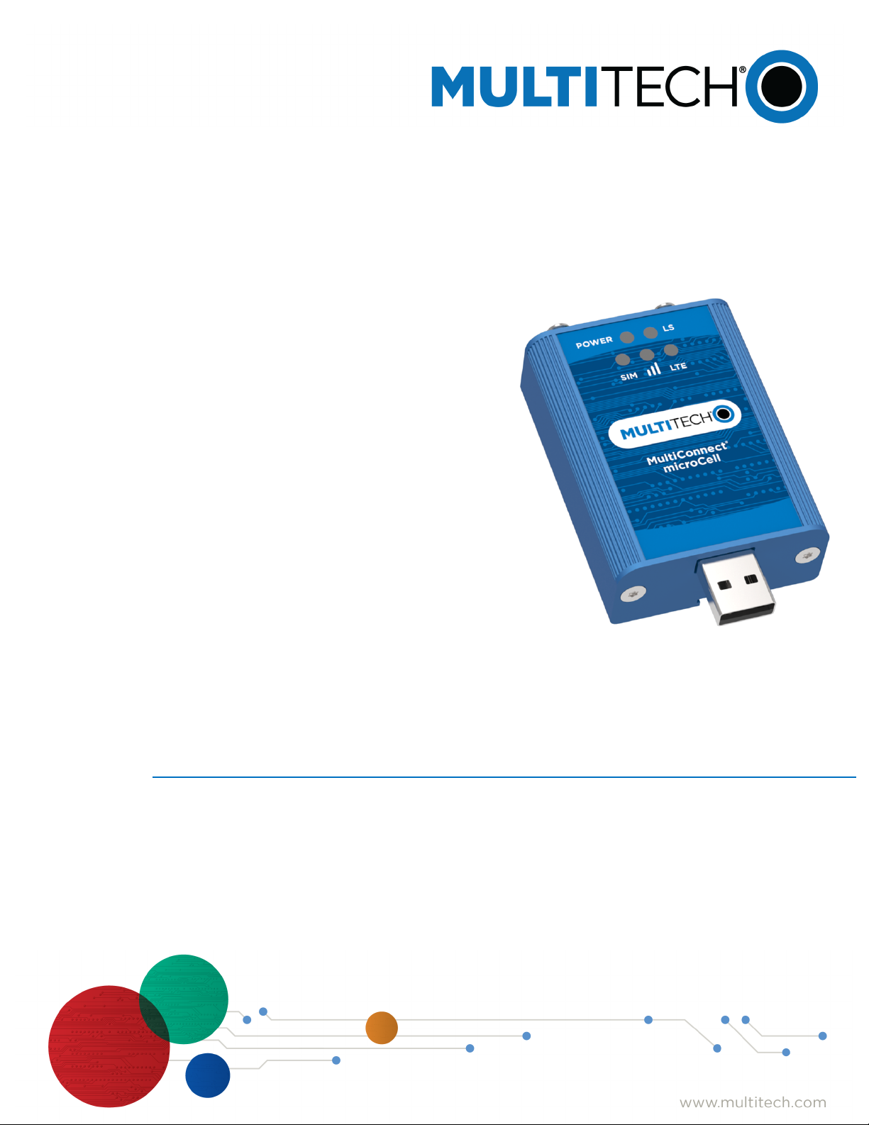
About the MultiConnect microCell Modem
The MultiConnect microCell is a compact and simple communications platform that provides cellular capabilities
for fixed and mobile applications. It is intended for use in settings such as vending, smart parking, medical, smart
inventory tracking equipment and commercial applications.
Documentation Overview
The following documents are available at https://www.multitech.com/brands/multiconnect-microcell. Select your
model to find the documents specific for that device.
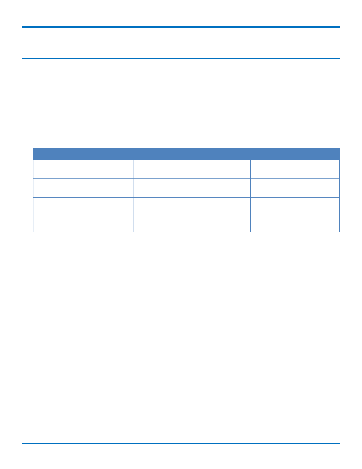
Document Description Part Number
MultiConnect microCell MTCM2L4G1 User Guide
MultiConnect microCell MTCM2L4G1 Quick Start
Quectel EGxx AT Commands
Manual, USB Installation Guides,
and other related manuals
Hardware, regulatory, and getting started
information.
Steps for getting started. Ships with the
device and is available online.
Multiple documents listing AT Commands,
USB installation guides, app notes, and
other protocols used to communicate
with your device. Provided in a zip file.
S000728
82104400L
N/A
MultiConnect®microCell MTCM2-L4G1 User Guide 5
Page 6
PRODUCT OVERVIEW
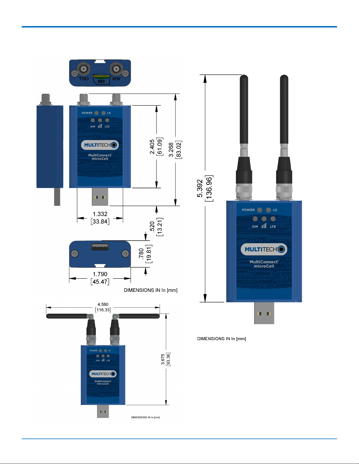
Dimensions
6 MultiConnect®microCell MTCM2-L4G1 User Guide
Page 7
MTCM2-L4G1 Specifications
Category Description
General
Standards 3GPP Rel. 11 LTE
UMTS/HSPA+
GSM/GPRS/EDGE
USB Interface is CDC-ACM compliant
TCP/IP Functions FTP, SMTP, SSL, TCP, UDP
Frequency Bands LTE FDD: B1/B2/B3/B4/B5/B7/B8/B12/B13/B18/ B19/B20/B25/B26/B28
LTE TDD: B38/B39/B40/B41
WCDMA: B1/B2/B4/B5/B8/B6/B19
GSM: B2/B3/B5/B8
Speed
PRODUCT OVERVIEW
Data Speed LTE FDD: Max 150Mbps (DL)/Max 50Mbps (UL)
LTE TDD: Max 130Mbps (DL)/Max 35Mbps (UL)
UMTS: DC-HSDPA: Max 42Mbps (DL)
UMTS: HSUPA: Max 5.76Mbps (UL)
UMTS: WCDMA: Max 384Kbps (DL)/Max 384Kbps (UL)
GSM: EDGE: Max 296Kbps (DL)/Max 236.8Kbps (UL)
GSM: GPRS: Max 107Kbps (DL)/Max 85.6Kbps (UL)
Physical Description
Weight Device only 2.4 oz (66 g); With antennas 2.9 oz (83 g)
Dimensions Refer to mechanical drawing for dimensions.
Connectors
Antenna Connector 2 SMA connectors for cellular
SIM 1.8V and 3V SIM holder for micro-SIM (3FF) card
USB USB 2.0 with High Speed up to 480 Mbps
Environment
Operating Temperature -40° C to +85° C*
Storage Temperature -40° C to +85° C
Humidity 20%-90% RH, non-condensing
Power Requirements
Operating Voltage USB Model: 5 VDC
SMS
MultiConnect®microCell MTCM2-L4G1 User Guide 7
Page 8
PRODUCT OVERVIEW
Category Description
SMS Point-to-Point messaging
Mobile-Terminated SMS
Mobile-Originated SMS
Certifications and Compliance
EMC and Radio
Compliance
Safety Compliance IEC 60950-1 2nd ED, IEC 62368-1
*UL tested to ambient temperature of +60C.
CE Mark, RED (EU)
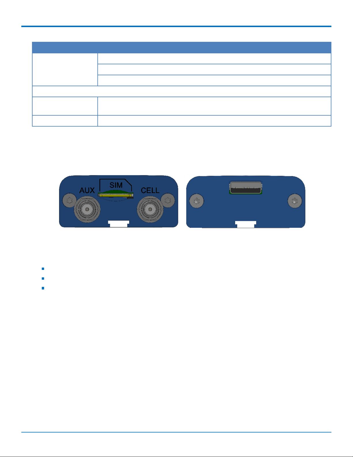
Side Panels and Connectors
Side Panels
Connectors
The device has the following connectors:
USB 1 USB connector
SMA 2 female SMA connectors, labeled CELL and AUX
SIM 1 micro-SIM slot, between the SMA connectors
8 MultiConnect®microCell MTCM2-L4G1 User Guide
Page 9
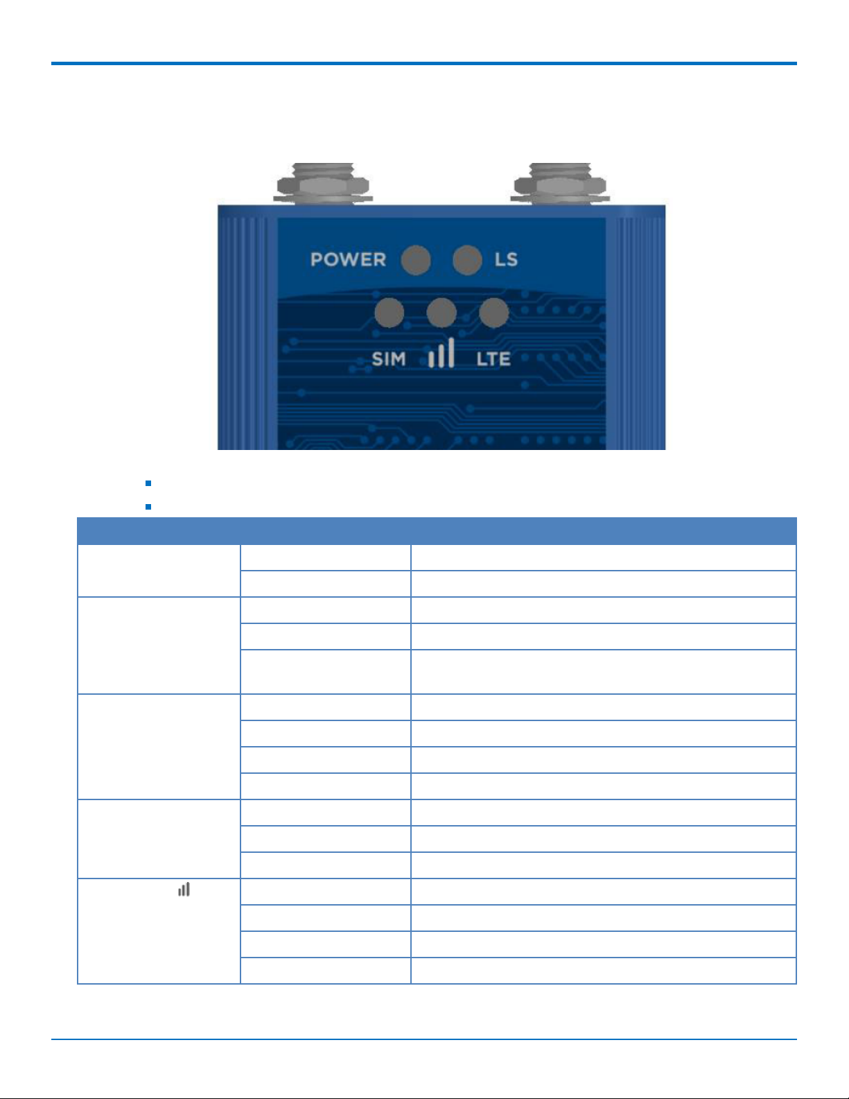
LED Descriptions
The MTCM2 has the following LEDs:
PRODUCT OVERVIEW
Note:
Slow is 1 second on 1 second off
Fast is 200 milliseconds on 200 milliseconds off
LED Status Description
Power On Device has power
Off Device does not have power
Link Status (LS) On Radio is not registered
Flash Slow Registered
Off Radio is turned off, in PSM mode, receiving a firmware
update, or SIM is not inserted.
LTE On LTE
Flash Fast 3G
Flash Slow 2G
Off SIM not inserted or radio technology unknown
SIM On Ready
Flash Slow Other
Off SIM not inserted
Signal Strength On Excellent
Flash Fast Good
Flash Slow Fair
Off No signal or SIM not inserted
MultiConnect®microCell MTCM2-L4G1 User Guide 9
Page 10

PRODUCT OVERVIEW
MTCM2-L4G1 Power Draw
Note: MultiTech recommends that you incorporate a 10% buffer into your power source when determining
product load.
Radio
Protocol
3G On/Off
Mode
Current or
Sleep Mode
Live
Connection,
Idle Current
Cellular
Connection
Idle, No
Data
Measured
Current at
Max Power
TX Pulse
Amplitude
1
Current for
Peak
Current
2
Total Inrush
Charge
3
Total
Inrush
Duration
During
Power Up
5 Volts
GSM850 N/A 67 mA 67 mA 354 mA 1.40 A 0.156 mC 26.1 uS
WCDMA Band
N/A 68 mA 67 mA 512 mA 580 mA 0.156 mC 26.1 uS
2 (1854MHz)
LTE Band 1
N/A 71 mA 68 mA 721 mA 788 mA 0.156 mC 26.1 uS
(1950MHz)
Note:
1. Maximum Power: The continuous current during maximum data rate with the radio transmitter at
maximum power.
2. TX Pulse: The average peak current during an HSDPA/LTE connection.
3. Inrush Charge: The total inrush charge at power on.
10 MultiConnect®microCell MTCM2-L4G1 User Guide
Page 11

SAFETY WARNINGS
Chapter 2 – Safety Warnings
Radio Frequency (RF) Safety
Due to the possibility of radio frequency (RF) interference, it is important that you follow any special regulations
regarding the use of radio equipment. Follow the safety advice given below.
Operating your device close to other electronic equipment may cause interference if the equipment is
inadequately protected. Observe any warning signs and manufacturers’ recommendations.
Different industries and businesses restrict the use of cellular devices. Respect restrictions on the use of
radio equipment in fuel depots, chemical plants, or where blasting operations are in process. Follow
restrictions for any environment where you operate the device.
Do not place the antenna outdoors.
Switch OFF your wireless device when in an aircraft. Using portable electronic devices in an aircraft may
endanger aircraft operation, disrupt the cellular network, and is illegal. Failing to observe this restriction
may lead to suspension or denial of cellular services to the offender, legal action, or both.
Switch OFF your wireless device when around gasoline or diesel-fuel pumps and before filling your vehicle
with fuel.
Switch OFF your wireless device in hospitals and any other place where medical equipment may be in use.
Interference with Pacemakers and Other Medical Devices
Potential interference
Radio frequency energy (RF) from cellular devices can interact with some electronic devices. This is
electromagnetic interference (EMI). The FDA helped develop a detailed test method to measure EMI of implanted
cardiac pacemakers and defibrillators from cellular devices. This test method is part of the Association for the
Advancement of Medical Instrumentation (AAMI) standard. This standard allows manufacturers to ensure that
cardiac pacemakers and defibrillators are safe from cellular device EMI.
The FDA continues to monitor cellular devices for interactions with other medical devices. If harmful interference
occurs, the FDA will assess the interference and work to resolve the problem.
Precautions for pacemaker wearers
If EMI occurs, it could affect a pacemaker in one of three ways:
Stop the pacemaker from delivering the stimulating pulses that regulate the heart's rhythm.
Cause the pacemaker to deliver the pulses irregularly.
Cause the pacemaker to ignore the heart's own rhythm and deliver pulses at a fixed rate.
Based on current research, cellular devices do not pose a significant health problem for most pacemaker wearers.
However, people with pacemakers may want to take simple precautions to be sure that their device doesn't cause
a problem.
Keep the device on the opposite side of the body from the pacemaker to add extra distance between the
pacemaker and the device.
Avoid placing a turned-on device next to the pacemaker (for example, don’t carry the device in a shirt or
jacket pocket directly over the pacemaker).
MultiConnect®microCell MTCM2-L4G1 User Guide 11
Page 12

INSTALLING THE DEVICE
Chapter 3 – Installing the Device
Installing a SIM Card
This model requires a SIM card, which is supplied by your service provider. To install the SIM card:
1. Locate the SIM card slot on the side of the modem. The slot is labeled SIM.
2. Slide the SIM card into the SIM card slot with the contact side facing up as shown. When the SIM card is
installed, it locks into place.
Removing a SIM Card
To remove the SIM card, push the SIM card in. The device ejects the SIM card.
Installing the Device
1. Connect antennas to the antenna connectors.
2. Connect the USB connector to your computer or other USB high power device, such as a hub.
3. The POWER LED lights after the device powers up.
Mounting Device to Flat Surface
1. Locate the groove on the bottom of the device.
2. Slide the mounting bracket through the groove.
12 MultiConnect®microCell MTCM2-L4G1 User Guide
Page 13

INSTALLING THE DEVICE
3. To secure the bracket to the desired surface, place and tighten two screws in the holes on either end of
the mounting bracket. The dimensions illustration in this guide shows the mounting bracket, as well as
the dimensions for placement of the screws.
MultiConnect®microCell MTCM2-L4G1 User Guide 13
Page 14

INSTALLING THE DEVICE
Next Steps
Before using the device:
Install drivers. Download drivers for your device at https://www.multitech.com/brands/multiconnect-
microcell. Select your model to find the drivers specific to your device. Driver documentation for both Linux
and Windows is included in the related documentation zip file.
To communicate with your device, use terminal software such as HyperTerminal, Tera Term, Kermit, or
Putty.
Power up your device and ensure it is connected to your computer that issues AT commands. AT command
documents are in the related documentation zip file at https://www.multitech.com/brands/multiconnect-
microcell. Select your model to find the zip file for your device.
Note: Wait 10 seconds after power-up before issuing any AT commands.
14 MultiConnect®microCell MTCM2-L4G1 User Guide
Page 15

ANTENNA INFORMATION
Chapter 4 – Antenna Information
Antenna
The antenna intended for use with this unit meets the requirements for mobile operating configurations and for
fixed mounted operations, as defined in 2.1091 and 1.1307 of the FCC rules for satisfying RF exposure compliance.
If an alternate antenna is used, consult user documentation for required antenna specifications.
Antenna System Cellular Devices
The cellular/wireless performance depends on the implementation and antenna design. The integration of the
antenna system into the product is a critical part of the design process; therefore, it is essential to consider it early
so the performance is not compromised. Devices were approved with the following antenna(s) and for alternate
antennas meeting the given specifications.
The antenna system is defined as the UFL connection point from the device to the specified cable specifications
and specified antenna specifications.
Cellular and LTE Antenna
Manufacturer: 2J
Manufacturer's Model Number: 2JW1024
Multi-Tech Systems: 45009891L
Antenna Specifications
Category Description
Frequency Range 698 - 960 MHz
1710 - 2170 MHz
2500 - 2700 MHz
Impedance 50 Ohms
VSWR VSWR should not exceed 2.0:1 at any point across the bands of operation
Peak Radiated Gain ~0.1 dBi
~2.9 dBi
~4.6 dBi
Radiation Omni-directional
Polarization Linear
Connector SMA(M)
MultiConnect®microCell MTCM2-L4G1 User Guide 15
Page 16

REGULATORY INFORMATION
Chapter 5 – Regulatory Information
EMC, Safety, and Radio Equipment Directive (RED) Compliance
The CE mark is affixed to this product to confirm compliance with the following European Community Directives:
Council Directive 2011/65/EU on the restriction of the use of certain hazardous substances in electrical
and electronic equipment;
and
Council Directive 2014/53/EU on radio equipment and telecommunications terminal equipment and the
mutual recognition of their conformity.
MultiTech declares that this device is in compliance with the essential requirements and other relevant provisions
of Directive 2014/53/EU. The declaration of conformity may be requested at https://support.multitech.com.
Waste Electrical and Electronic Equipment Statement
Note: This statement may be used in documentation for your final product applications.
WEEE Directive
The WEEE Directive places an obligation on EU-based manufacturers, distributors, retailers, and importers to takeback electronics products at the end of their useful life. A sister directive, ROHS (Restriction of Hazardous
Substances) complements the WEEE Directive by banning the presence of specific hazardous substances in the
products at the design phase. The WEEE Directive covers all MultiTech products imported into the EU as of August
13, 2005. EU-based manufacturers, distributors, retailers and importers are obliged to finance the costs of recovery
from municipal collection points, reuse, and recycling of specified percentages per the WEEE requirements.
Instructions for Disposal of WEEE by Users in the European Union
The symbol shown below is on the product or on its packaging, which indicates that this product must not be
disposed of with other waste. Instead, it is the user's responsibility to dispose of their waste equipment by handing
it over to a designated collection point for the recycling of waste electrical and electronic equipment. The separate
collection and recycling of your waste equipment at the time of disposal will help to conserve natural resources
and ensure that it is recycled in a manner that protects human health and the environment. For more information
about where you can drop off your waste equipment for recycling, please contact your local city office, your
household waste disposal service or where you purchased the product.
July, 2005
16 MultiConnect®microCell MTCM2-L4G1 User Guide
Page 17

REGULATORY INFORMATION
REACH Statement
Registration of Substances
Multi-Tech Systems, Inc. confirms that none of its products or packaging contain any of the Substances of Very
High Concern (SVHC) on the REACH Candidate List, in a concentration above the 0.1% by weight allowable limit
The latest 197 substances restricted per the REACH Regulation were last updated January 2019. Refer to the
following for the most current candidate list of substances: http://echa.europa.eu/candidate-list-table.
Restriction of the Use of Hazardous Substances (RoHS)
Multi-Tech Systems, Inc.
Certificate of Compliance
2015/863
Multi-Tech Systems, Inc. confirms that its embedded products comply with the chemical concentration limitations
set forth in the directive 2015/863 of the European Parliament (Restriction of the use of certain Hazardous
Substances in electrical and electronic equipment - RoHS).
These MultiTech products do not contain the following banned chemicals1:
Lead, [Pb] < 1000 PPM
Mercury, [Hg] < 100 PPM
Cadmium, [Cd] < 100 PPM
Hexavalent Chromium, [Cr+6] < 1000 PPM
Polybrominated Biphenyl, [PBB] < 1000 PPM
Polybrominated Diphenyl Ethers, [PBDE] < 1000 PPM
Bis(2-Ethylhexyl) phthalate (DEHP): < 1000 ppm
Benzyl butyl phthalate (BBP): < 1000 ppm
Dibutyl phthalate (DBP): < 1000 ppm
Diisobutyl phthalate (DIBP): < 1000 ppm
Environmental considerations:
Moisture Sensitivity Level (MSL) =1
Maximum Soldering temperature = 260C (in SMT reflow oven)
1
Lead usage in some components is exempted by the following RoHS annex, therefore higher lead concentration
would be found in some modules (>1000 PPM);
- Resistors containing lead in a glass or ceramic matrix compound.
MultiConnect®microCell MTCM2-L4G1 User Guide 17
Page 18

REGULATORY INFORMATION
Information on HS/TS Substances According to Chinese Standards
In accordance with China's Administrative Measures on the Control of Pollution Caused by Electronic Information
Products (EIP) # 39, also known as China RoHS, the following information is provided regarding the names and
concentration levels of Toxic Substances (TS) or Hazardous Substances (HS) which may be contained in Multi-Tech
Systems Inc. products relative to the EIP standards set by China's Ministry of Information Industry (MII).
Hazardous/Toxic Substance/Elements
Name of the Component Lead
(PB)
Printed Circuit Boards O O O O O O
Resistors X O O O O O
Capacitors X O O O O O
Ferrite Beads O O O O O O
Relays/Opticals O O O O O O
ICs O O O O O O
Diodes/ Transistors O O O O O O
Oscillators and Crystals X O O O O O
Regulator O O O O O O
Voltage Sensor O O O O O O
Transformer O O O O O O
Speaker O O O O O O
Connectors O O O O O O
Mercury
(Hg)
Cadmium
(CD)
Hexavalent
Chromium
(CR6+)
Polybromi
nated
Biphenyl
(PBB)
Polybrominat
ed Diphenyl
Ether (PBDE)
LEDs O O O O O O
Screws, Nuts, and other
Hardware
AC-DC Power Supplies O O O O O O
Software /Documentation CDs O O O O O O
Booklets and Paperwork O O O O O O
Chassis O O O O O O
X Represents that the concentration of such hazardous/toxic substance in all the units of homogeneous
material of such component is higher than the SJ/Txxx-2006 Requirements for Concentration Limits.
O Represents that no such substances are used or that the concentration is within the aforementioned limits.
18 MultiConnect®microCell MTCM2-L4G1 User Guide
X O O O O O
Page 19

REGULATORY INFORMATION
Information on HS/TS Substances According to Chinese Standards (in Chinese)
依依照照中中国国标标准准的的有有毒毒有有害害物物质质信信息息
根据中华人民共和国信息产业部 (MII) 制定的电子信息产品 (EIP) 标准-中华人民共和国《电子信息产品污染
控制管理办法》(第 39 号),也称作中国 RoHS, 下表列出了 Multi-Tech Systems, Inc. 产品中可能含有的有毒
物质 (TS) 或有害物质 (HS) 的名称及含量水平方面的信息。
有有害害//有有毒毒物物质质//元元素素
成成分分名名称称
印刷电路板
电阻器
电容器
铁氧体磁环
继电器/光学部件
ICs O O O O O O
二极管/晶体管
振荡器和晶振
调节器
电压传感器
变压器
扬声器
连接器
LEDs O O O O O O
铅铅 (PB) 汞汞 (Hg) 镉镉 (CD) 六六价价铬铬 (CR6+)
O O O O O O
X O O O O O
X O O O O O
O O O O O O
O O O O O O
O O O O O O
X O O O O O
O O O O O O
O O O O O O
O O O O O O
O O O O O O
O O O O O O
多多溴溴联联苯苯
(PBB)
多多溴溴二二苯苯醚醚
(PBDE)
螺丝、螺母以及其它五金件
交流-直流电源
软件/文档 CD
手册和纸页
底盘
X 表示所有使用类似材料的设备中有害/有毒物质的含量水平高于 SJ/Txxx-2006 限量要求。
O 表示不含该物质或者该物质的含量水平在上述限量要求之内。
MultiConnect®microCell MTCM2-L4G1 User Guide 19
X O O O O O
O O O O O O
O O O O O O
O O O O O O
O O O O O O
Page 20

USING CONNECTION MANAGER
Chapter 6 – Using Connection Manager
Use Connection Manager to:
Install the latest device drivers.
Activate and connect your device to your carrier’s network.
Note:
Connection Manager can install drivers and connect your device regardless of your cellular network;
however, activation is only supported with Verizon, Aeris, Sprint, and some regional carriers. If you
cannot activate your device with Connection Manager, refer to Account Activation for Cellular
Devices.
MTD-H5 models use SIM-based activation. If you do not have a SIM card, contact your carrier.
Switch the firmware in your device to a different carrier (if supported by your device).
Manage cellular connection and automatically reconnect with the keep-alive feature.
View device details.
View line charts of signal level and data rates.
Use a terminal window for communicating with and troubleshooting the device.
Installing Connection Manager
Connection Manager installs the appropriate drivers for USB devices along with the application. Serial devices do
not require drivers.
Note: Attempting to plug in the device before the appropriate drivers are installed can cause the connection to
fail.
To install Connection Manager and the device drivers:
1. Go to https://www.multitech.com/support/connection-manager.
2. Click Connection Manager.
3. Open or unzip the Connection Manager file and run the installer (.msi file).
4. In the MultiTech Connection Manager Setup Wizard, read the end-user license agreement and check I
accept the terms in the License Agreement.
5. Click Next to have the installer automatically disable the native WWAN AutoConfig service in Windows.
The WWAN AutoConfig service manages mobile broadband connections. Connection Manager requires
that this service be disabled.
Note: This page appears only on Windows 10.
6. If a MultiTech device is connected to the computer, disconnect it and click Next.
7. If you use a USB device, check Install the modem driver.
CAUTION: Unless you are certain that the drivers for your USB device are already installed on the
computer, make sure that you check Install the modem driver. Failure to do this will cause the
application to incorrectly detect your device or not detect the device at all.
Note: Because serial devices do not require drivers, it does not matter if you check or uncheck
Install the modem driver for a serial device.
20 MultiConnect®microCell MTCM2-L4G1 User Guide
Page 21

USING CONNECTION MANAGER
8. To specify a folder for Connection Manager, use the default folder or click Change to browse to the folder
you want to use.
9. Click Install.
A separate wizard opens for installing Telit drivers. Some MultiTech devices use embedded modules from
Telit Wireless Solutions to provide cellular connectivity; these devices require Telit drivers.
10. Select Complete setup type.
11. When the drivers are installed, click Finish.
12. In the Setup Wizard, click Finish.
Note:
To open Connection Manager after installation, check Start the MultiTech Connection
Manager when the installation is finished.
After the drivers are installed, you need to restart your computer if prompted by Windows.
If using a USB device, you can connect the device to the carrier's network with Connection Manager. Refer to
Connecting a Device.
If using a serial device, you need to set up the device in Windows Device Manager before connecting the device.
Refer to Setting Up a Serial Device in Windows Device Manager.
Setting Up a Serial Device in Windows Device Manager
To set up the device in Windows Device Manager:
1. Make sure that your desired COM port for the serial device is available.
2. Connect the serial device to the PC.
3. Go to Control Panel > Device Manager. Make a note of the COM port number for the connected device
(in COM Ports).
Example: The COM port is COM31.
4. Go to Action > Add legacy hardware.
MultiConnect®microCell MTCM2-L4G1 User Guide 21
Page 22

USING CONNECTION MANAGER
5. In the Add Hardware Wizard:
a. Click Next.
b. Select Install the hardware that I manually select from a list, then click Next.
c. Select Modems, then click Next.
d. Check Don't detect my modem; I will select it from a list, then click Next.
e. Select Standard Modem Types, then select Standard 33600 bps Modem on the right.
Important: Make sure that you select only Standard 33600 bps Modem. Selecting another model
may cause your device to work incorrectly or fail.
f. Select your COM port, then click Next.
g. Click Finish.
h. Go to Device Manager > Modems and confirm that the device is added.
6. To verify that the device is set up correctly, query the device:
a. Go to Device Manager > Modems, right-click Standard 33600 bps Modem, and select Properties.
b. On the Diagnostics tab, click Query Modem.
Note: The device cannot be queried if the Connection Manager is running and using the device's
port.
If the device is ready, diagnostic information from the device appears in the box above.
To connect the device to your carrier's network, refer to Connecting a Device.
22 MultiConnect®microCell MTCM2-L4G1 User Guide
Page 23

USING CONNECTION MANAGER
Connecting a Device
Before You Begin
Make sure that your device is connected to the computer where Connection Manager is installed.
Set up the device in Device Manager. Refer to Setting Up a Serial Device in Windows Device Manager.
To connect your device to the carrier's network:
1. Open Connection Manager.
Connection Manager automatically detects the connected device, and the Detect button on the Main tab
changes to Connect. If the application cannot detect the device automatically, click Detect to initiate
device detection manually.
2. If you are connecting the device to this computer for the first time, on the Connection dialog box, provide
values for the connection settings, such as the dial number and access point name (APN).
You may need to ask the carrier for these settings.
a. To monitor Internet connectivity, have Connection Monitor send periodic pings to a host, check
Enable keep-alive and enter the IP address or host name to ping in the Host to ping box. For
example, you can enter the host name google.com or IP address 8.8.8.8.
If the keep-alive check fails, Connection Manager automatically reconnects. When the keep-alive
feature is enabled, the Connection Manager's Main tab displays the keep-alive check status and
when the last ping response was received.
b. If your device supports dual carriers, switch the firmware to the desired carrier by selecting the
carrier in the MNO Firmware list. For example, if your device can switch the firmware between
AT&T and Verizon, select Verizon in the list.
Note:
The MNO Firmware list doesn't appear if your device doesn't support carrier firmware
switching.
When you change the carrier firmware, the modem automatically restarts to apply the
selected firmware.
c. To save the settings, click Apply.
You can change the connection settings on the Connection tab. The Dial number, APN, User name,
and Password cannot be changed after the device is connected.
3. On the Settings tab, select USB Modem or Serial Modem depending on whether you are connecting a
USB or serial device.
4. If you are connecting a serial device, provide the serial settings on the Settings tab:
a. In the Modem type list, select the appropriate modem type.
b. For the other settings, provide the values that match the serial-port settings for the device in Device
Manager.
For Port, expand Ports and notice the COM port number next to the device name. Right-click the
device name, select Properties, and find the values for the other settings on the Port Settings tab.
c. To save the settings, click Apply.
Note:
MultiConnect®microCell MTCM2-L4G1 User Guide 23
Page 24

USING CONNECTION MANAGER
Settings displayed for a USB device on the Settings tab are determined automatically and cannot
be changed.
To set the application to run during Windows startup, check Run application at Windows startup.
To automatically connect to the Internet, check Connect to the Internet automatically.
Selecting Run application at Windows startup and Connect to the Internet automatically is useful in
scenarios where Connection Manager is running on a remote computer. If a power failure occurs on the
computer, these settings ensure the application will restart and reconnect to the Internet when power is
restored.
5. On the Main tab, click Connect.
When a connection is established, the Main tab displays the download and upload speeds, the amount of
traffic sent and received, Connected status, and the signal strength percentage and bars. The statistics on
connection speeds and traffic are available only during a current connection session.
Note:
For serial modems, the signal strength is available only when the device is not connected to the
carrier's network. When connection to the network is established, the last signal strength value is
displayed.
View the details for the current connection on the Details tab.
6. To disconnect the device from the carrier's network, click Disconnect.
Uninstalling Connection Manager
Along with uninstalling Connection Manager, the installed device drivers are also removed.
Before You Begin
Make sure that Connection Manager is not running.
To uninstall Connection Manager:
1. In Windows, go to Control Panel > Programs > Programs and Features.
2. Right-click MultiTech Connection Manager and select Uninstall.
3. Click Yes to confirm that you want to uninstall Connection Manager.
The native Windows WWAN AutoConfig service is automatically enabled.
4. When the message "Are you sure you want to uninstall this product?" appears, click Yes.
Connection Manager and the installed drivers are removed from the computer.
Note: The steps above describe how to uninstall Connection Manager using Control Panel. You can also
uninstall the application by using the installer file (.msi). Double-click the file, in the MultiTech Connection
Manager Setup Wizard, click Next, and then select Remove on the next two pages.
Connection Manager User Interface
Connection Manager consists of the following tabs:
Main
Settings
24 MultiConnect®microCell MTCM2-L4G1 User Guide
Page 25

Connection
Details
Terminal
Charts
USING CONNECTION MANAGER
Main tab
The Main tab displays the following:
Status of device connection: Searching, Connecting, Connected, Disconnecting, or Disconnected
The action button, which changes according to the current device connection status: Detect, Connect, or
Disconnect
Signal strength bars and percentage indicator (only when connection to the carrier's network is established)
Note: The signal strength is displayed for a serial device only when the device is not connected to the
carrier's network.
Connection statistics: download and upload speeds, amount of traffic sent and received (only when
connection to the carrier's network is established)
The keep-alive check status and when the last ping response was received if Enable keep-alive check is
checked on the Connection tab.
MultiConnect®microCell MTCM2-L4G1 User Guide 25
Page 26

USING CONNECTION MANAGER
Settings tab
Use the Settings tab to specify the type of device: USB Modem or Serial Modem.
If USB Modem is selected, the tab displays USB settings. These settings cannot be edited.
If Serial Modem is selected, the tab displays the serial settings that match the serial-port settings for the
device. You can edit these settings.
The Settings tab also contains the Run application at Windows startup and Connect to the Internet automatically
options.
Check Run application at Windows startup to open Connection Manager when Windows starts.
Check Connect to the Internet automatically to set Connection Manager to connect to the carrier's network
automatically each time the application opens.
Connection tab
The Connection tab displays the following:
The carrier-provided connection settings.
The Enable keep-alive check box. Check this box to monitor connectivity to the Internet. Check Enable
keep-alive check and enter the IP address or host name to ping in the Host to ping box. Connection
Monitor will send periodic pings to the host. If the keep-alive feature fails, Connection Manager will
automatically reconnect.
The MNO firmware list. If your device supports dual carriers, you can switch the firmware to the other
carrier by selecting the carrier in this list.
Note: The Connection tab isn't available if Connection Manager doesn't detect a device.
Details tab
The Details tab displays the modem details when a device is detected and the connection details when a
connection is established.
Terminal tab
The Terminal tab contains a terminal window to communicate with the connected device by entering AT
commands. For details, refer to the AT Commands reference guide for your device.
Note: When a serial device is connected to the carrier's network, the terminal window isn't available.
Charts tab
The Charts tab contains line charts that graphically represent signal strength and download and upload speeds for
the 2-hour interval.
Troubleshooting
Serial COM port is not available in the Serial Modem Settings
Close Connection Manager and reopen it.
Device is not detected ("No Device")
After following the steps to activate your device, the Main tab still indicates "No Device."
26 MultiConnect®microCell MTCM2-L4G1 User Guide
Page 27

USING CONNECTION MANAGER
Try the following steps:
1. Click the Settings tab and make sure that the appropriate modem type is selected: USB or Serial.
2. If you are connecting a serial device, make sure that all serial modem settings correspond to the
serial modem and serial port configuration.
3. Restart Connection Manager.
4. Disconnect and reconnect the device.
MultiConnect Cell USB Modem is not detected
1. Check the Power and LS LEDs on the device. If they are not continuously lit, then the problem is with
the power supply. Check the cable and connections.
2. USB device: Make sure that the device is connected to the PC and that the correct USB cable is in use.
Connection Manager is not working, and a device connected to the computer is not detected
Connection Manager cannot detect a connected device because the required drivers are not installed. The most
likely cause is that Install the modem drivers was not checked during the installation.
Uninstall and re-install Connection Manager. During the installation, make sure that you check Install the modem
driver. Refer to Uninstalling Connection Manager and Installing Connection Manager.
Connection Manager displays "Device Error" status for a serial device
This error has the following causes and solutions.
Cause Solution
Connection Manager cannot open the COM port that
the device was installed on because the port is being
used by another program.
The wrong COM port is specified for the device on the
Settings tab.
If possible, free up the COM port for the device.
On the Settings tab, select the COM port that matches
the port that the device is installed on and click Apply.
You can look up the port in Device Manager in
Windows. In Device Manager, expand Modems, rightclick the name of your device, and select Properties.
Note the port on the Modem tab.
MultiConnect®microCell MTCM2-L4G1 User Guide 27
 Loading...