

Page 1
®
MultiConnect
MTCDT-LAP3 Hardware Guide (AU)
Conduit
TM
Page 2

MULTICONNECT® CONDUITTM HARDWARE GUIDE
MultiConnect®ConduitTMHardware Guide
Models: MTCDT-LAP3-246A-915-AU, MTCDT-LAP3-246A-AU
Part Number: S000718
Copyright
This publication may not be reproduced, in whole or in part, without the specific and express prior written permission signed by an executive officer of
Multi-Tech Systems, Inc. All rights reserved. Copyright © 2019 by Multi-Tech Systems, Inc.
Multi-Tech Systems, Inc. makes no representations or warranties, whether express, implied or by estoppels, with respect to the content, information,
material and recommendations herein and specifically disclaims any implied warranties of merchantability, fitness for any particular purpose and noninfringement.
Multi-Tech Systems, Inc. reserves the right to revise this publication and to make changes from time to time in the content hereof without obligation of
Multi-Tech Systems, Inc. to notify any person or organization of such revisions or changes.
Legal Notices
The MultiTech products are not designed, manufactured or intended for use, and should not be used, or sold or re-sold for use, in connection with
applications requiring fail-safe performance or in applications where the failure of the products would reasonably be expected to result in personal injury or
death, significant property damage, or serious physical or environmental damage. Examples of such use include life support machines or other life
preserving medical devices or systems, air traffic control or aircraft navigation or communications systems, control equipment for nuclear facilities, or
missile, nuclear, biological or chemical weapons or other military applications (“Restricted Applications”). Use of the products in such Restricted
Applications is at the user’s sole risk and liability.
MULTITECH DOES NOT WARRANT THAT THE TRANSMISSION OF DATA BY A PRODUCT OVER A CELLULAR COMMUNICATIONS NETWORK WILL BE
UNINTERRUPTED, TIMELY, SECURE OR ERROR FREE, NOR DOES MULTITECH WARRANT ANY CONNECTION OR ACCESSIBILITY TO ANY CELLULAR
COMMUNICATIONS NETWORK. MULTITECH WILL HAVE NO LIABILITY FOR ANY LOSSES, DAMAGES, OBLIGATIONS, PENALTIES, DEFICIENCIES, LIABILITIES,
COSTS OR EXPENSES (INCLUDING WITHOUT LIMITATION REASONABLE ATTORNEYS FEES) RELATED TO TEMPORARY INABILITY TO ACCESS A CELLULAR
COMMUNICATIONS NETWORK USING THE PRODUCTS.
The MultiTech products and the final application of the MultiTech products should be thoroughly tested to ensure the functionality of the MultiTech
products as used in the final application. The designer, manufacturer and reseller has the sole responsibility of ensuring that any end user product into
which the MultiTech product is integrated operates as intended and meets its requirements or the requirements of its direct or indirect customers.
MultiTech has no responsibility whatsoever for the integration, configuration, testing, validation, verification, installation, upgrade, support or maintenance
of such end user product, or for any liabilities, damages, costs or expenses associated therewith, except to the extent agreed upon in a signed written
document. To the extent MultiTech provides any comments or suggested changes related to the application of its products, such comments or suggested
changes is performed only as a courtesy and without any representation or warranty whatsoever.
Contacting MultiTech
Knowledge Base
The Knowledge Base provides immediate access to support information and resolutions for all MultiTech products. Visit http://www.multitech.com/kb.go.
Support Portal
To create an account and submit a support case directly to our technical support team, visit: https://support.multitech.com.
Support
Business Hours: M-F, 8am to 5pm CT
Country By Email By Phone
Europe, Middle East, Africa: support@multitech.co.uk +(44) 118 959 7774
U.S., Canada, all others: support@multitech.com (800) 972-2439 or (763) 717-5863
Warranty
To read the warranty statement for your product, visit www.multitech.com/warranty.go. For other warranty options, visit www.multitech.com/es.go.
World Headquarters
Multi-Tech Systems, Inc.
2205 Woodale Drive, Mounds View, MN 55112
Phone: (800) 328-9717 or (763) 785-3500
Fax (763) 785-9874
2 MultiConnect®ConduitTMMTCDT-LAP3 Hardware Guide (AU)
Page 3

CONTENTS
Contents
Chapter 1 – Product Overview ................................................................................................................................. 4
Introduction .................................................................................................................................................................. 4
Product Kit Contents ..................................................................................................................................................... 5
Build Options................................................................................................................................................................. 6
Chapter 2 – Specifications ........................................................................................................................................ 7
Conduit Specifications................................................................................................................................................... 7
Mechanical Drawing...................................................................................................................................................... 8
Backpanel Connectors .................................................................................................................................................. 9
LED Descriptions ......................................................................................................................................................... 10
Chapter 3 – Antenna Information .......................................................................................................................... 12
Wieson Antenna.......................................................................................................................................................... 12
Antenna Specifications ............................................................................................................................................. 12
Chapter 4 – Setting up and Configuring the Device ................................................................................................ 13
Install and Connect Conduit Hardware....................................................................................................................... 13
Installing a Mini SIM Card ........................................................................................................................................... 13
Accessory Port (mCard) Interfaces.............................................................................................................................. 14
Installing a Micro SD Card........................................................................................................................................... 15
Installing a Battery ...................................................................................................................................................... 16
Connecting to the Debug Interface............................................................................................................................. 17
Restoring User Defined Settings ................................................................................................................................. 18
Resetting the Device ................................................................................................................................................... 18
Powering Up the device .............................................................................................................................................. 19
Chapter 5 – Regulatory Information ....................................................................................................................... 20
Regulatory Compliance Mark (RCM)........................................................................................................................... 20
Restriction of the Use of Hazardous Substances (RoHS) ............................................................................................ 20
REACH Statement ....................................................................................................................................................... 21
Registration of Substances........................................................................................................................................ 21
Substances of Very High Concern (SVHC) ................................................................................................................ 21
Waste Electrical and Electronic Equipment Statement .............................................................................................. 21
WEEE Directive.......................................................................................................................................................... 21
Instructions for Disposal of WEEE by Users in the European Union ........................................................................ 21
Information on HS/TS Substances According to Chinese Standards ......................................................................... 23
Information on HS/TS Substances According to Chinese Standards (in Chinese) ...................................................... 24
MultiConnect®ConduitTMMTCDT-LAP3 Hardware Guide (AU) 3
Page 4
PRODUCT OVERVIEW
Chapter 1 – Product Overview
Introduction
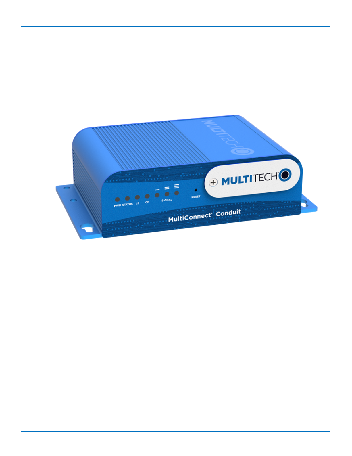
MultiConnect®Conduit™ is a programmable gateway that uses an open Linux development environment to enable
machine-to-machine (M2M) connectivity using various wireless interfaces. It also provides an online application
store for industrial things as a platform for developers to provision and manage their gateway and associated
sensors and devices.
4 MultiConnect®ConduitTMMTCDT-LAP3 Hardware Guide (AU)
Page 5
Product Kit Contents
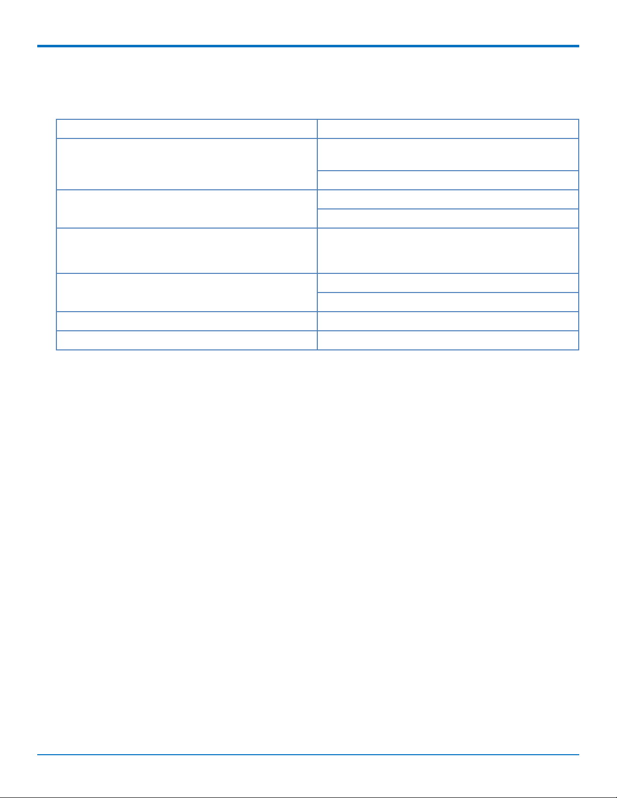
Your product kit typically includes the following (varies with model):
PRODUCT OVERVIEW
Device 1 - MTCDT-Conduit
1
Power Supply 1 - 100-240V 9V-1.7A power supply with removable
blades
1 - AU blade/plug
Cables 1 - Micro USB Cable
1 - Ethernet Cable RJ45 6-ft.
Antennas 1 - Hepta Band SMA (for non-LTE devices) or 2 - LTE
SMA (for Conduit LTE only), 1 - GPS antenna, and 1 - WiFi/Bluetooth antenna
2
Customer Notices Quick Start
Registration Card
Feet 4 - Clear Adhesive Feet
Additional 1 - Promotional screwdriver
Note 1: MTCDT-LAP3-246A-915-AU and MTCDT-LAP3-246L-915-AU include a LoRa Accessory Card.
Note 2: HEPTA or LTE antennas are not included with MTCDT-246 or 247A/L (No Radio versions).
MultiConnect®ConduitTMMTCDT-LAP3 Hardware Guide (AU) 5
Page 6
PRODUCT OVERVIEW
Build Options
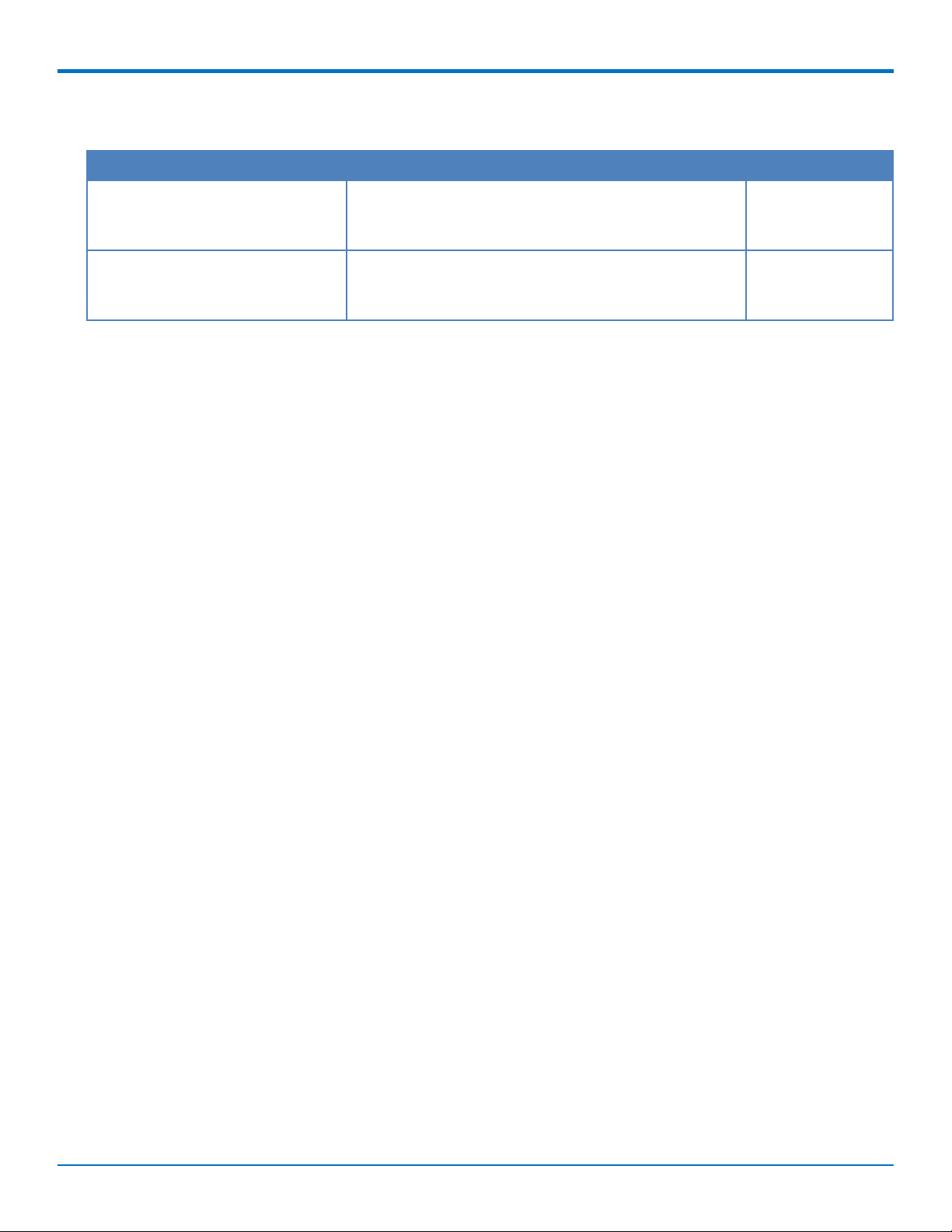
Product Description Region
MTCDT-LAP3-246A-915-AU Conduit 4G LTE Cat 1 w/ 3G Fallback Application
Enablement Programmable Gateway using GNSS w/AU
Accessory Kit and LoRa Accessory Card
MTCDT-LAP3-246A-AU Conduit 4G LTE Cat 1 w/ 3G Fallback Application
Enablement Programmable Gateway using GNSS w/AU
Accessory Kit
Australia
Australia
6 MultiConnect®ConduitTMMTCDT-LAP3 Hardware Guide (AU)
Page 7
Chapter 2 – Specifications
Conduit Specifications
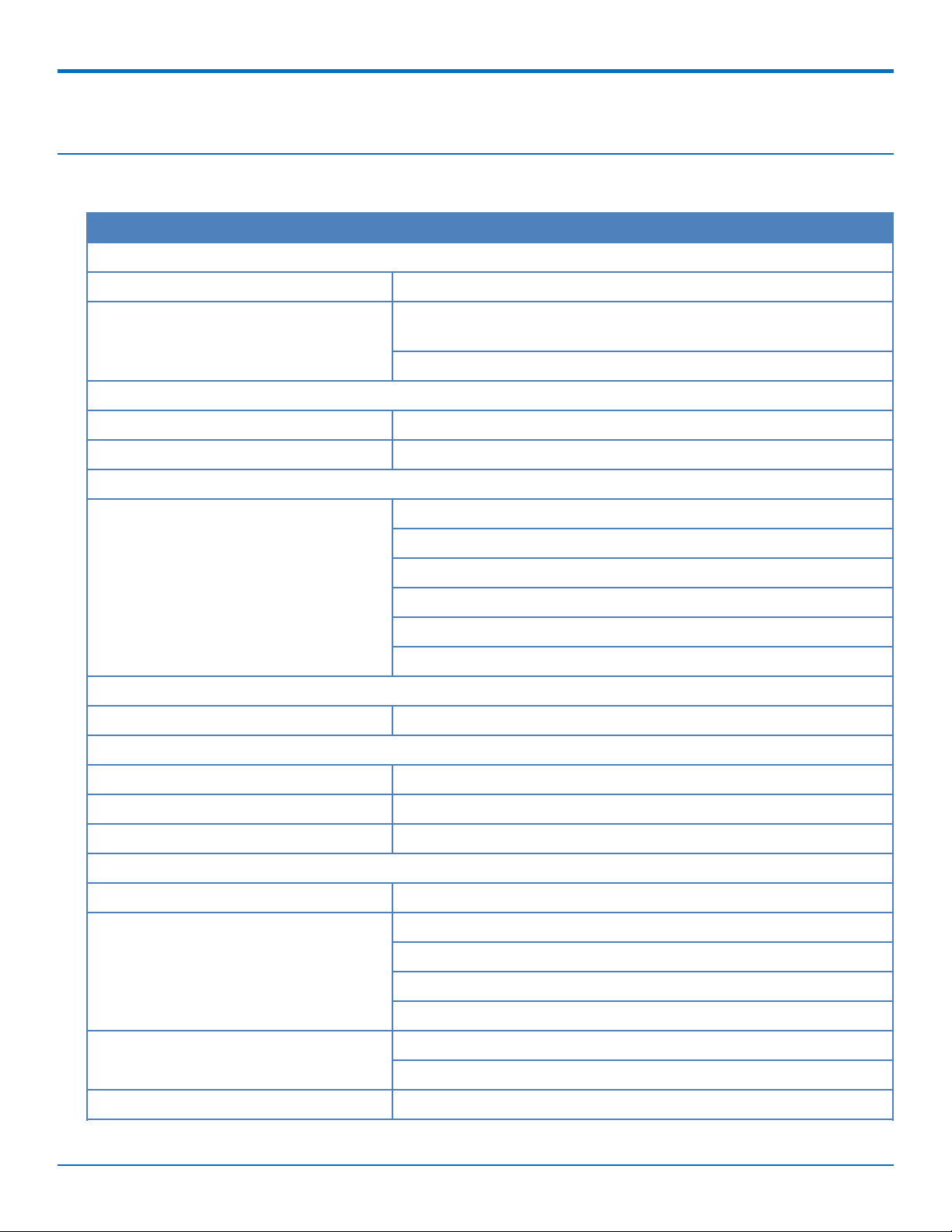
Category Description
General
Performance 4G LTE Cat 1 with 3G Fallback Release 9
Frequency Bands (MHz) 4G LTE Cat 1 FDD 2100 (B1), 850 (B5) , 900 (B8), 1800 (B3), and 700
(B28)
3G WCDMA 2100 (B1), GSM 850 (B5), and EGSM 900 (B8)
Physical Description
Dimensions See the Conduit Demensions Drawing
Weight 15.6 oz. (442.25 grams) with no accessory cards installed
Connectors
SPECIFICATIONS
Connectors 1 USB device micro Type B debug port (behind nameplate)
1 RJ-45 Ethernet port
1 USB micro port
2 cellular antenna connectors
1 Wi-Fi/Bluetooth connector
1 GPS antenna connector
Power Requirements
Input Voltage 9-32 Volts
Environment
Operating Environment -30° to +70° C
Storage Environment -40° to +85° C
Relative Humidity 20 to 90% non-condensing
Certifications
Country Approval RCM (Australia)
Radio & EMC Compliance EN 55022:2010
EN 301 489
1
FCC Part 15 Class B
IC Class B
Safety Compliance UL/cUL 60950-1 2nd Ed.
IEC 60950-1 2nd Ed. Am. 1 and Am. 2
Telecom Approvals Telstra
MultiConnect®ConduitTMMTCDT-LAP3 Hardware Guide (AU) 7
Page 8
SPECIFICATIONS
1
UL Listed @ 40° C, limited by AC power supply. UL Recognized @ 65° C for Conduit LTE devices within IP67
enclosure or when used with the fused DC power cable, part number FPC-532-DC.
Installation in outdoor locations or ambient above 70° C has not been evaluated by UL. UL Certification does not
apply or extend to use in outdoor applications.
Optional power must be UL Listed ITE power supply marked LPS or Class 2 rated 12 VDC, 5A. Certification does not
apply or extend to Voltages outside certified range, and has not been evaluated by UL for operating voltages
beyond tested range.
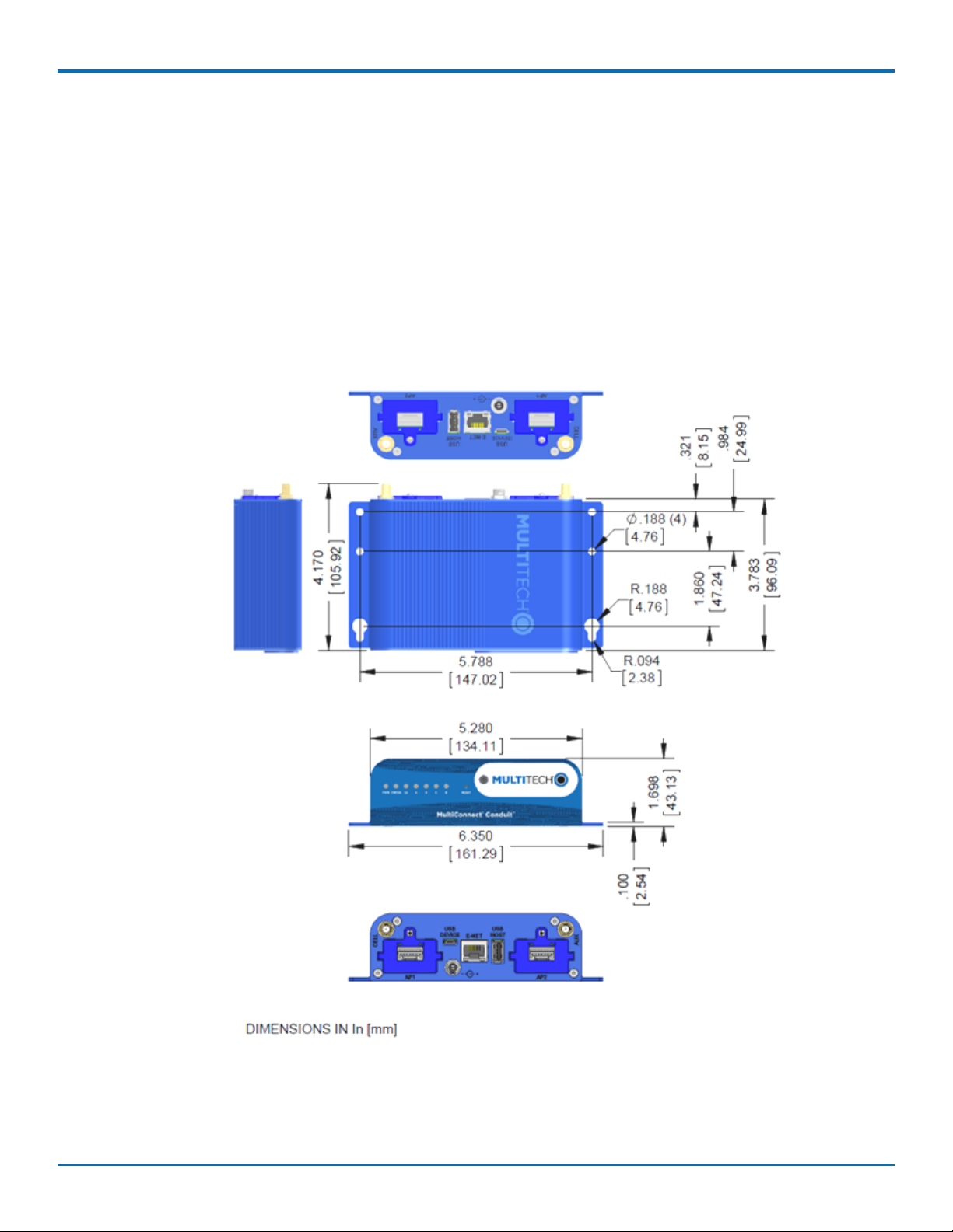
Mechanical Drawing
8 MultiConnect®ConduitTMMTCDT-LAP3 Hardware Guide (AU)
Page 9

SPECIFICATIONS
Backpanel Connectors
Label Description
CELL, AUX Cellular antenna inputs.
H5: CELL - Primary. AUX - Diversity.
AP1, AP2 Slots for MultiTech accessory cards. You can install an accessory card in either slot. Both slots
can be occupied at one time. An exception is an SDIO (Secure Digital Input/Output) card,
which can be used only in the AP1 slot.
USB DEVICE User-defined, high-speed 480 Mbps, standard USB 2.0 Micro B connector. Use this port to
connect the Conduit to a computer or another device. By default, this port is a serial port
terminal interface, but you can program it to act as another device such as a mass storage
device or an Ethernet port.
E-NET RJ-45 receptacle for standard Ethernet 10/100 Base-T.
Caution: Ethernet ports and command ports are not designed to be connected to a public
telecommunication network or used outside the building or campus.
USB HOST High-speed, standard USB 2.0 Type A connector. 500mA maximum current draw. You can
plug into the Host port a device such as a flash drive, camera, or printer if the Linux kernel
has the appropriate driver.
Power 9-32 Vdc power receptacle for provided power cord.
MultiConnect®ConduitTMMTCDT-LAP3 Hardware Guide (AU) 9
Page 10

SPECIFICATIONS
LED Descriptions
Conduit mLinux Model Front Panel
Conduit Application Model Front Panel
Label Name Description
PWR Power Solid (constant) green if unit is on indicating that DC power is present.
STATUS Power Status Default condition: LED blinks when mLinux is fully loaded.
LS Link Status Varies with radio model.
A-B-C-D -- These 4 LEDs are user-specified. Present on the Conduit mLinux model only.
CD Carrier Detect This LED is on when a cellular data connection is made. Present on the
Conduit Application model only.
Signal Signal Strength These 3 LEDs display the strength of the cellular signal. Present on the
Conduit Application model only.
If a cellular radio is installed, the typical LS (Link Status) LED behavior is the following:
OFF - No power to the cellular radio
Continuously Lit - Not registered
Slow Blink (-0.2Hz) - Registered or connected
10 MultiConnect®ConduitTMMTCDT-LAP3 Hardware Guide (AU)
Page 11

SPECIFICATIONS
On the back of the Conduit, the RJ-45 Ethernet LEDs (located at the bottom of the connector) are defined as
follows:
Orange LED (lower-left) indicated activity/link. Blinks when there is transmit and receive on the
Ethernet link. It shows a steady light when there is a valid Ethernet connection.
Green LED (lower-right) indicates link speed. Lit when Ethernet is linked at 100Mbps. If not lit, Ethernet
is linked at 10 Mbps.
MultiConnect®ConduitTMMTCDT-LAP3 Hardware Guide (AU) 11
Page 12

ANTENNA INFORMATION
Chapter 3 – Antenna Information
Wieson Antenna
Devices were approved with the following antenna:
Manufacturer: Wieson
Description: LTE GY115HT467-017
Model Number: 11320Y11194A1
MultiTech ordering information:
Model Quantity
ANLTE2-1HRA 1
ANLTE2-10HRA 10
ANLTE2-50HRA 50
Antenna Specifications
Category Description
Frequency Range .069~0.96GHz, 1.71~2.17GHz, 2.3GHz~2.69GHz
Impedance 50 Ohms
VSWR VSWR should not exceed 3:1 at any point across the bands of operation
Peak Gain 3.8 dBi
Radiation Omni-directional
Polarization Linear Vertical
12 MultiConnect®ConduitTMMTCDT-LAP3 Hardware Guide (AU)
Page 13

SETTING UP AND CONFIGURING THE DEVICE
Chapter 4 – Setting up and Configuring the Device
Install and Connect Conduit Hardware
To install and cable the device:
1. Install a Mini SIM card.
2. Install a Micro SD card (optional).
3. Install a battery (optional).
4. Connect the supplied antenna to the CELL connector on the back of the device.
5. Use the Ethernet connector to connect the Conduit to the device used to administer the Conduit.
6. Install any mCard accessory cards into a slot at the back of the device. Refer to Installing an mCard
Accessory Card for instructions.
7. Depending on the accessory card type, attach any antennas or cables for use with the card.
8. Connect the power cord to an outlet or power strip and to the power adapter.
9. Connect the power adapter to the barrel jack on the back panel of the device. The Power LED comes on
immediately after power is applied. Wait for the Status LED to begin blinking.
Installing a Mini SIM Card
You need:
Phillips screwdriver
Mini SIM card (2FF form factor)
To install or replace the SIM card:
1. Disconnect power to the Conduit, if it is connected.
2. At the front of the Conduit housing, remove the screw that secures the nameplate to the housing and
remove the nameplate.
3. Locate the SIM card holder in the upper right corner of the opening. If a SIM card is installed and needs to
be removed, slide it out of the SIM card holder.
4. Gently push the new SIM card into SIM card holder face up with the cut corner to the right and the SIM
contacts facing toward the Conduit’s interior.
5. If not installing a battery or micro SD card, reattach the MultiTech nameplate to the Conduit using the
screw removed in Step 2.
MultiConnect®ConduitTMMTCDT-LAP3 Hardware Guide (AU) 13
Page 14

SETTING UP AND CONFIGURING THE DEVICE
Accessory Port (mCard) Interfaces
The accessory card interface on the Conduit base board has the following interface options:
Interface Description
I2C Used by all accessory cards. I2C is required for
Electronic Identification (EID) support on the accessory
card but can be used for other I2C devices. It should
supports standard (100 kHz) and/or fast (400 kHz) clock
speeds.
The I2C interface reserves the full block of EEPROM
address space for Electronic ID support, so we
recommend that you not attach any other EEPROM
devices to the interface. We recommend that you use a
24C04 part, because both address bits of the 24C04 are
connected to the AP interface allowing you to identify
four separate accessory port (AP) cards in a system.
Serial UART Serial UART with HW flow control used by Serial
inteface based Accessory Cards
SDIO interface and/or SPI Interface AP1 has option for SDIO or SPI interface, based on what
Accessory Card is installed. AP2 supports only SPI based
Accessory Cards.
GPIO Additional control pins for certain Accessory Cards.
Interrupts Software defined interrupts. Can also be used as
additional control pins.
14 MultiConnect®ConduitTMMTCDT-LAP3 Hardware Guide (AU)
Page 15

SETTING UP AND CONFIGURING THE DEVICE
Interface Description
PPS GPS generated Pulse-Per-Second signal used for
software timing. Default is 1 pulse/sec.
USB 2.0 A standard USB 2.0 High Speed interface for USB based
Accessory Cards.
5 VDC 1 Amp supply Used by all accessory cards.
3.3 VDC 1 Amp supply Used by all accessory cards.
For accessory card specifications, regulatory content, and installation information, see the Accessory Card
information.
Installing a Micro SD Card
You need:
Phillips screwdriver
MicroSD memory card
To install or replace the SD card:
1. Disconnect power to the Conduit, if it is connected.
2. At the front of the Conduit, remove the screw that secures the MultiTech nameplate.
3. Locate the SD card at the left side of the opening on the underside of the PC board.
4. If an SD card is already installed, gently push on the card to release it from its setting and remove it from
the housing with your fingers.
5. With the new SD card contacts facing up and toward the interior of the device, gently push the card into
the slot to secure it.
6. Reattach the MultiTech nameplate to the housing using the screw removed in step 2.
MultiConnect®ConduitTMMTCDT-LAP3 Hardware Guide (AU) 15
Page 16

SETTING UP AND CONFIGURING THE DEVICE
Installing a Battery
The battery is located in the Conduit housing.
You need:
Phillips screwdriver
If replacing a battery, non-metal tweezers or similar object
CR1632 standard coin lithium battery
To install or replace the battery:
1. If connected, disconnect power to the Conduit.
2. At the front of the Conduit housing, remove the screw that secures the MultiTech nameplate to the
housing.
3. The battery holder is located at the right side of the opening on the underside of the PC board. To
remove an existing battery, use non-metal tweezers as necessary.
4. Orient the new battery so that the positive (+) pole is facing down. Use your fingers or non-metal
tweezers to insert the battery into the holder.
5. Reattach the MultiTech nameplate to the housing using the screw removed in Step 2.
16 MultiConnect®ConduitTMMTCDT-LAP3 Hardware Guide (AU)
Page 17

SETTING UP AND CONFIGURING THE DEVICE
CAUTION: Risk of explosion if this battery is replaced by an incorrect type. Dispose of batteries according to
instructions.
Note:
ATTENTION: Risque d’explosion si vous remplacez la batterie par un modèle incompatible. Jetez
les piles usagées selon les instructions.
Connecting to the Debug Interface
You need:
Phillips screwdriver
Standard USB Micro B cable
To connect the debug cable:
1. Disconnect power to the Conduit, if it is connected.
2. At the front of the Conduit housing, remove the screw that secures the MultiTech nameplate to the
housing.
3. Locate the USB debug cable connector in the center of the opening.
4. Connect the USB Micro B cable to the debug connector.
5. Connect the Type A end of the USB cable to the host.
6. From the host, use an application such as TeraTerm with a baud rate of 115,200. If the USB driver does
not automatically install, do the following:
a. Unplug the USB cable.
b. Go to the following web site to download and install the appropriate USB driver:
https://www.exar.com/connectivity/uart-and-bridging-solutions/usb-uarts/xr21b1411/
c. Plug the USB cable back into the housing.
7. From the host, access the Conduit's USB COM port.
MultiConnect®ConduitTMMTCDT-LAP3 Hardware Guide (AU) 17
Page 18

SETTING UP AND CONFIGURING THE DEVICE
Restoring User Defined Settings
You need:
A pin, paperclip, or similar thin object that can fit into the reset hole.
To restore user defined settings for an AEP device:
1. Locate the hole in the panel labeled RESET. The reset button is recessed into the housing.
2. Use the pin to press in the button for between 3 to 29 seconds, then release the reset button.
If you do not press in the button long enough, the device will reset, but the user defined settings will
not be restored.
If you hold it too long (30 seconds or longer), factory default settings will be restored.
Note: The RESET button is in the same location on all Conduit models.
Resetting the Device
You need:
A pin, paperclip, or similar thin object that can fit into the reset hole.
The following is the default condition for the RESET button on the Conduit. You can program a change to the
behavior of the button if needed.
To reset the device:
1. Find the hole in the front panel labeled RESET. The reset button is recessed into the case.
2. For AEP: Use the pin to press the RESET button for less than 3 seconds, then release. The device reboots.
For mLinux: Press and hold the RESET button for less than 5 seconds, then release. Holding it beyond 5
seconds resets an mLinux device to factory defaults.
3. The status LED will keep blinking normally for a couple of seconds until the unit resets. Then the status
light will stay solid while the device reboots. Once finished, the status will resume blinking normally.
18 MultiConnect®ConduitTMMTCDT-LAP3 Hardware Guide (AU)
Page 19

SETTING UP AND CONFIGURING THE DEVICE
Powering Up the device
CAUTION: Use only the power cord provided with the device. Using any other power cord voids the warranty
and can damage the device.
To power up the device:
1. Install the desired MultiTech accessory card or cards into the slots at the back of the device. Refer to the
appropriate installation documentation for the accessory card.
2. Connect the power cord to an outlet or power strip and to the power adapter.
3. Connect the power adapter to the barrel jack on the back panel of the device.
4. Verify power.
The Power LED comes on immediately after power is applied.
The device takes a short time to boot up when you apply power.
5. Connect the device to the controlling device through the Ethernet connector or the USB connector on the
back panel.
MultiConnect®ConduitTMMTCDT-LAP3 Hardware Guide (AU) 19
Page 20

REGULATORY INFORMATION
Chapter 5 – Regulatory Information
Regulatory Compliance Mark (RCM)
This product complies with the requirements of the Regulatory Compliance Mark (RCM) for Electrical Regulatory
Authorities Council (ERAC), Electrical Equipment Safety System (EESS), and the Australian Communications and
Media Authority (ACMA) for Electromagnetic Compatibility (EMC).
Restriction of the Use of Hazardous Substances (RoHS)
Multi-Tech Systems, Inc.
Certificate of Compliance
2011/65/EU
Multi-Tech Systems, Inc. confirms that its embedded products comply with the chemical concentration limitations
set forth in the directive 2011/65/EU of the European Parliament (Restriction of the use of certain Hazardous
Substances in electrical and electronic equipment - RoHS).
These MultiTech products do not contain the following banned chemicals1:
Lead, [Pb] < 1000 PPM
Mercury, [Hg] < 1000 PPM
Hexavalent Chromium, [Cr+6] < 1000 PPM
Cadmium, [Cd] < 100 PPM
Polybrominated Biphenyl, [PBB] < 1000 PPM
Polybrominated Diphenyl Ether, [PBDE] < 1000 PPM
Environmental considerations:
Moisture Sensitivity Level (MSL) =1
Maximum Soldering temperature = 260C (in SMT reflow oven)
1
Lead usage in some components is exempted by the following RoHS annex, therefore higher lead concentration
would be found in some modules (>1000 PPM);
20 MultiConnect®ConduitTMMTCDT-LAP3 Hardware Guide (AU)
Page 21

REGULATORY INFORMATION
- Resistors containing lead in a glass or ceramic matrix compound.
REACH Statement
Registration of Substances
After careful review of the legislation and specifically the definition of an “article” as defined in EC Regulation
1907/2006, Title II, Chapter 1, Article 7.1(a)(b), it is our current view that Multi-Tech Systems, Inc. products would
be considered as “articles.” In light of the definition in § 7.1(b) which requires registration of an article only if it
contains a regulated substance that “is intended to be released under normal or reasonably foreseeable conditions
of use,” our analysis is that Multi-Tech Systems, Inc. products constitute nonregisterable articles for their intended
and anticipated use.
Substances of Very High Concern (SVHC)
Per the candidate list of Substances of Very High Concern (SVHC) published October 28, 2008 we have reviewed
these substances and certify the Multi-Tech Systems, Inc. products are compliant per the EU “REACH”
requirements of less than 0.1% (w/w) for each substance. If new SVHC candidates are published by the European
Chemicals Agency, and relevant substances have been confirmed to be greater than 0.1% (w/w), Multi-Tech
Systems, Inc. will provide updated compliance status.
Multi-Tech Systems, Inc. also declares it has been duly diligent in ensuring that the products supplied are compliant
through a formalized process which includes collection and validation of materials declarations and selective
materials analysis where appropriate. This data is controlled as part of a formal quality system and will be made
available upon request.
Waste Electrical and Electronic Equipment Statement
Note: This statement may be used in documentation for your final product applications.
WEEE Directive
The WEEE Directive places an obligation on EU-based manufacturers, distributors, retailers, and importers to takeback electronics products at the end of their useful life. A sister directive, ROHS (Restriction of Hazardous
Substances) complements the WEEE Directive by banning the presence of specific hazardous substances in the
products at the design phase. The WEEE Directive covers all MultiTech products imported into the EU as of August
13, 2005. EU-based manufacturers, distributors, retailers and importers are obliged to finance the costs of recovery
from municipal collection points, reuse, and recycling of specified percentages per the WEEE requirements.
Instructions for Disposal of WEEE by Users in the European Union
The symbol shown below is on the product or on its packaging, which indicates that this product must not be
disposed of with other waste. Instead, it is the user's responsibility to dispose of their waste equipment by handing
it over to a designated collection point for the recycling of waste electrical and electronic equipment. The separate
collection and recycling of your waste equipment at the time of disposal will help to conserve natural resources
and ensure that it is recycled in a manner that protects human health and the environment. For more information
about where you can drop off your waste equipment for recycling, please contact your local city office, your
household waste disposal service or where you purchased the product.
July, 2005
MultiConnect®ConduitTMMTCDT-LAP3 Hardware Guide (AU) 21
Page 22

REGULATORY INFORMATION
22 MultiConnect®ConduitTMMTCDT-LAP3 Hardware Guide (AU)
Page 23

REGULATORY INFORMATION
Information on HS/TS Substances According to Chinese Standards
In accordance with China's Administrative Measures on the Control of Pollution Caused by Electronic Information
Products (EIP) # 39, also known as China RoHS, the following information is provided regarding the names and
concentration levels of Toxic Substances (TS) or Hazardous Substances (HS) which may be contained in Multi-Tech
Systems Inc. products relative to the EIP standards set by China's Ministry of Information Industry (MII).
Hazardous/Toxic Substance/Elements
Name of the Component Lead
(PB)
Printed Circuit Boards O O O O O O
Resistors X O O O O O
Capacitors X O O O O O
Ferrite Beads O O O O O O
Relays/Opticals O O O O O O
ICs O O O O O O
Diodes/ Transistors O O O O O O
Oscillators and Crystals X O O O O O
Regulator O O O O O O
Voltage Sensor O O O O O O
Transformer O O O O O O
Speaker O O O O O O
Connectors O O O O O O
Mercury
(Hg)
Cadmium
(CD)
Hexavalent
Chromium
(CR6+)
Polybromi
nated
Biphenyl
(PBB)
Polybrominat
ed Diphenyl
Ether (PBDE)
LEDs O O O O O O
Screws, Nuts, and other
Hardware
AC-DC Power Supplies O O O O O O
Software /Documentation CDs O O O O O O
Booklets and Paperwork O O O O O O
Chassis O O O O O O
X Represents that the concentration of such hazardous/toxic substance in all the units of homogeneous
material of such component is higher than the SJ/Txxx-2006 Requirements for Concentration Limits.
O Represents that no such substances are used or that the concentration is within the aforementioned limits.
MultiConnect®ConduitTMMTCDT-LAP3 Hardware Guide (AU) 23
X O O O O O
Page 24

REGULATORY INFORMATION
Information on HS/TS Substances According to Chinese Standards (in Chinese)
依依照照中中国国标标准准的的有有毒毒有有害害物物质质信信息息
根据中华人民共和国信息产业部 (MII) 制定的电子信息产品 (EIP) 标准-中华人民共和国《电子信息产品污染
控制管理办法》(第 39 号),也称作中国 RoHS, 下表列出了 Multi-Tech Systems, Inc. 产品中可能含有的有毒
物质 (TS) 或有害物质 (HS) 的名称及含量水平方面的信息。
有有害害//有有毒毒物物质质//元元素素
成成分分名名称称
印刷电路板
电阻器
电容器
铁氧体磁环
继电器/光学部件
ICs O O O O O O
二极管/晶体管
振荡器和晶振
调节器
电压传感器
变压器
扬声器
连接器
LEDs O O O O O O
铅铅 (PB) 汞汞 (Hg) 镉镉 (CD) 六六价价铬铬 (CR6+)
O O O O O O
X O O O O O
X O O O O O
O O O O O O
O O O O O O
O O O O O O
X O O O O O
O O O O O O
O O O O O O
O O O O O O
O O O O O O
O O O O O O
多多溴溴联联苯苯
(PBB)
多多溴溴二二苯苯醚醚
(PBDE)
螺丝、螺母以及其它五金件
交流-直流电源
软件/文档 CD
手册和纸页
底盘
X 表示所有使用类似材料的设备中有害/有毒物质的含量水平高于 SJ/Txxx-2006 限量要求。
O 表示不含该物质或者该物质的含量水平在上述限量要求之内。
24 MultiConnect®ConduitTMMTCDT-LAP3 Hardware Guide (AU)
X O O O O O
O O O O O O
O O O O O O
O O O O O O
O O O O O O
 Loading...