

Page 1
MultiConnect
TM
Conduit
Hardware Guide
®
Page 2

MULTICONNECT® CONDUIT HARDWARE GUIDE
MultiConnect®Conduit Hardware Guide
Model: MTCDT
Part Number: S000690
Copyright
This publication may not be reproduced, in whole or in part, without the specific and express prior written permission signed by an executive officer of
Multi-Tech Systems, Inc. All rights reserved. Copyright © 2018 by Multi-Tech Systems, Inc.
Multi-Tech Systems, Inc. makes no representations or warranties, whether express, implied or by estoppels, with respect to the content, information,
material and recommendations herein and specifically disclaims any implied warranties of merchantability, fitness for any particular purpose and noninfringement.
Multi-Tech Systems, Inc. reserves the right to revise this publication and to make changes from time to time in the content hereof without obligation of
Multi-Tech Systems, Inc. to notify any person or organization of such revisions or changes.
Legal Notices
The MultiTech products are not designed, manufactured or intended for use, and should not be used, or sold or re-sold for use, in connection with
applications requiring fail-safe performance or in applications where the failure of the products would reasonably be expected to result in personal injury or
death, significant property damage, or serious physical or environmental damage. Examples of such use include life support machines or other life
preserving medical devices or systems, air traffic control or aircraft navigation or communications systems, control equipment for nuclear facilities, or
missile, nuclear, biological or chemical weapons or other military applications (“Restricted Applications”). Use of the products in such Restricted
Applications is at the user’s sole risk and liability.
MULTITECH DOES NOT WARRANT THAT THE TRANSMISSION OF DATA BY A PRODUCT OVER A CELLULAR COMMUNICATIONS NETWORK WILL BE
UNINTERRUPTED, TIMELY, SECURE OR ERROR FREE, NOR DOES MULTITECH WARRANT ANY CONNECTION OR ACCESSIBILITY TO ANY CELLULAR
COMMUNICATIONS NETWORK. MULTITECH WILL HAVE NO LIABILITY FOR ANY LOSSES, DAMAGES, OBLIGATIONS, PENALTIES, DEFICIENCIES, LIABILITIES,
COSTS OR EXPENSES (INCLUDING WITHOUT LIMITATION REASONABLE ATTORNEYS FEES) RELATED TO TEMPORARY INABILITY TO ACCESS A CELLULAR
COMMUNICATIONS NETWORK USING THE PRODUCTS.
The MultiTech products and the final application of the MultiTech products should be thoroughly tested to ensure the functionality of the MultiTech
products as used in the final application. The designer, manufacturer and reseller has the sole responsibility of ensuring that any end user product into
which the MultiTech product is integrated operates as intended and meets its requirements or the requirements of its direct or indirect customers.
MultiTech has no responsibility whatsoever for the integration, configuration, testing, validation, verification, installation, upgrade, support or maintenance
of such end user product, or for any liabilities, damages, costs or expenses associated therewith, except to the extent agreed upon in a signed written
document. To the extent MultiTech provides any comments or suggested changes related to the application of its products, such comments or suggested
changes is performed only as a courtesy and without any representation or warranty whatsoever.
Contacting MultiTech
Knowledge Base
The Knowledge Base provides immediate access to support information and resolutions for all MultiTech products. Visit http://www.multitech.com/kb.go.
Support Portal
To create an account and submit a support case directly to our technical support team, visit: https://support.multitech.com.
Support
Business Hours: M-F, 8am to 5pm CT
Country By Email By Phone
Europe, Middle East, Africa: support@multitech.co.uk +(44) 118 959 7774
U.S., Canada, all others: support@multitech.com (800) 972-2439 or (763) 717-5863
Warranty
To read the warranty statement for your product, visit www.multitech.com/warranty.go. For other warranty options, visit www.multitech.com/es.go.
World Headquarters
Multi-Tech Systems, Inc.
2205 Woodale Drive, Mounds View, MN 55112
Phone: (800) 328-9717 or (763) 785-3500
Fax (763) 785-9874
2 MultiConnect®ConduitTMHardware Guide
Page 3

CONTENTS
Contents
Chapter 1 – Product Overview ................................................................................................................................. 4
Introduction .................................................................................................................................................................. 4
Product Kit Contents ..................................................................................................................................................... 5
Build Options................................................................................................................................................................. 6
Chapter 2 – Specifications ........................................................................................................................................ 8
Conduit Specifications................................................................................................................................................... 8
Mechanical Drawing...................................................................................................................................................... 9
Backpanel Connectors ................................................................................................................................................ 10
LED Descriptions ......................................................................................................................................................... 11
Chapter 3 – Power Draw ........................................................................................................................................ 13
MTCDT-H5-246 with Modem and No Accessory Cards Power Draw ....................................................................... 13
MTCDT-LEU1-246 with Modem and No Accessory Cards......................................................................................... 13
MTCDT-LVW2-246 with Modem and No Accessory Cards ....................................................................................... 14
MTCDT-246A No Modem and No Accessory Cards .................................................................................................. 14
MTCDT-210 with Modem and no Accessory Cards Power Draw................................................................................ 16
MTCDT-LEU1-210 with Modem and no Accessory Cards Power Draw .................................................................... 16
MTCDT- LAT1-210 with Modem and No Accessory Cards........................................................................................ 17
MTCDT-LVW2-210 with Modem and No Accessory Cards ....................................................................................... 17
MTCDT-210 No Modem and No Accessory Cards .................................................................................................... 18
MTCDT-LEU1-247 with Bluetooth, Wi-Fi, and No Accessory Cards Power Draw ....................................................... 19
Chapter 4 – Frequency Information ....................................................................................................................... 20
Frequency Bands for Conduit...................................................................................................................................... 20
Frequency and Power Information for WiFi/Bluetooth.............................................................................................. 20
Frequency and Power Information for LoRa............................................................................................................... 20
Max Radio Frequency Power for Conduit ................................................................................................................. 20
Chapter 5 – Setting up and Configuring the Device ................................................................................................ 22
Install and Connect Conduit Hardware....................................................................................................................... 22
Installing a Mini SIM Card ........................................................................................................................................... 22
Accessory Port (mCard) Interfaces.............................................................................................................................. 23
Installing a Micro SD Card........................................................................................................................................... 24
Installing a Battery ...................................................................................................................................................... 25
Connecting to the Debug Interface............................................................................................................................. 26
Restoring User Defined Settings ................................................................................................................................. 27
Resetting the Device ................................................................................................................................................... 27
Powering Up the device .............................................................................................................................................. 28
Chapter 6 – Regulatory Information ....................................................................................................................... 29
Conduit Regulatory Information ................................................................................................................................. 29
MultiConnect®ConduitTMHardware Guide 3
Page 4
PRODUCT OVERVIEW
Chapter 1 – Product Overview
Introduction
Conduit™ is a programmable gateway that uses an open Linux development environment to enable machine-tomachine (M2M) connectivity using various wireless interfaces. It also provides an online application store for
industrial things as a platform for developers to provision and manage their gateway and associated sensors and
devices.
4 MultiConnect®ConduitTMHardware Guide
Page 5

PRODUCT OVERVIEW
Product Kit Contents
Your Product Kit includes the following:
Device 1 - MTCDT-Conduit
Power Supply 1 - 100-240V 9V-1.7A power supply with removable
blades
1 - NAM blade/plug
1 - EURO blade/plug
1 - UK blade/plug
Cables 1 - Micro USB Cable
1 - Ethernet Cable RJ45 6-ft.
Antennas* 1 - Hepta Band SMA (for non-LTE devices) or 2 - LTE
SMA (for Conduit LTE only), 1 - GPS antenna, and 1 - WiFi/Bluetooth antenna
Customer Notices Quick Start*
Registration Card
Feet 4 - Clear Adhesive Feet
Additional 1 - Promotional screwdriver
Note: *HEPTA or LTE antennas are not included with MTCDT-246 or 247A/L (No Radio versions).
MultiConnect®ConduitTMHardware Guide 5
Page 6

PRODUCT OVERVIEW
Build Options
Product Description Region
MTCDT-246L-US-EU-GB mLinux Programmable Gateway using GNSS
w/US/EU/UK Accessory Kit
MTCDT-246A-US-EU-GB Application Enablement Gateway using GNSS
w/US/EU/UK Accessory Kit
MTCDT-H5-246L-US-EU-GB HSPA+ mLinux Programmable Gateway using GNSS
w/US/EU/UK Acc Kit
MTCDT-H5-246A-US-EU-GB HSPA+ Application Enablement Gateway using GNSS
w/US/EU/UK Acc Kit
MTCDT-LEU1-246L-US-EU-GB Conduit LTE mLinux Programmable Gateway using
GNSS w/US/EU/UK Acc Kit
MTCDT-LEU1-246A-US-EU-GB Conduit LTE Application Enablement Programmable
Gateway using GNSS w/US/EU/UK Acc Kit
MTCDT-LAT1-246L-US Conduit LTE mLinux Programmable Gateway using
GNSS w/US/EU/UK Acc Kit
MTCDT-LAT1-246A-US Conduit LTE Application Enablement Programmable
Gateway using GNSS w/US/EU/UK Acc Kit
MTCDT-LVW2-246L-US Conduit LTE mLinux Programmable Gateway using
GNSS w/US/EU/UK Acc Kit
MTCDT-LVW2-246A-US Conduit LTE Application Enablement Programmable
Gateway using GNSS w/US/EU/UK Acc Kit
Global
Global
Global
Global
Global
Global
NA
NA
NA
NA
MTCDT-LDC3-246A-JP Conduit 4G LTE Cat 1 Application Enablement
Programmable Gateway using GNSS w/Japan Acc Kit
MTCDT-LDC3-246L-JP Conduit 4G LTE Cat 1 mLinux Programmable Gateway
using GNSS w/Japan Acc Kit
MTCDT-LDC3-246A-923-JP Conduit 4G LTE Cat 1 Application Enablement
Programmable Gateway using GNSS w/Japan Acc Kit
(AS 923 Channel Plan)
MTCDT-LDC3-246L-923-JP Conduit 4G LTE Cat 1 mLinux Programmable Gateway
using GNSS w/Japan Acc Kit (AS 923 Channel Plan)
MTCDT-247L-US-EU-GB mLinux Programmable Gateway using GNSS and
WiFi/BT w/US/EU/UK Accessory Kit
MTCDT-247A-US-EU-GB Application Enablement Gateway using GNSS and
WiFi/BT w/US/EU/UK Accessory Kit
MTCDT-H5-247L-US-EU-GB HSPA+ mLinux Programmable Gateway using GNSS and
WiFi/BT w/US/EU/UK Acc Kit
MTCDT-H5-247A-US-EU-GB HSPA+ Application Enablement Gateway using GNSS
and WiFi/BT w/US/EU/UK Acc Kit
Japan
Japan
Japan
Japan
Global
Global
Global
Global
6 MultiConnect®ConduitTMHardware Guide
Page 7

PRODUCT OVERVIEW
Product Description Region
MTCDT-LEU1-247L-US-EU-GB Conduit LTE mLinux Programmable Gateway using
GNSS and WiFi/BT w/US/EU/UK Acc Kit
MTCDT-LEU1-247A-US-EU-GB Conduit LTE Application Enablement Programmable
Gateway using GNSS and WiFi/BT w/US/EU/UK Acc Kit
MTCDT-LAT1-247L-US Conduit LTE mLinux Programmable Gateway using
GNSS and WiFi/BT w/US/EU/UK Acc Kit
MTCDT-LAT1-247A-US Conduit LTE Application Enablement Programmable
Gateway using GNSS and WiFi/BT w/US/EU/UK Acc Kit
MTCDT-LVW2-247L-US Conduit LTE mLinux Programmable Gateway using
GNSS and WiFi/BT w/US/EU/UK Acc Kit
MTCDT-LVW2-247A-US Conduit LTE Application Enablement Programmable
Gateway using GNSS and WiFi/BT w/US/EU/UK Acc Kit
Note:
The complete product code may end in .Rx. For example, MTCDT-H5.Rx, where R is the revision and
the x is the revision number.
210 models use pervious hardware and software (not upgraded to latest version).
Global
Global
NA
NA
NA
NA
MultiConnect®ConduitTMHardware Guide 7
Page 8

SPECIFICATIONS
Chapter 2 – Specifications
Conduit Specifications
Category Description
Physical Description
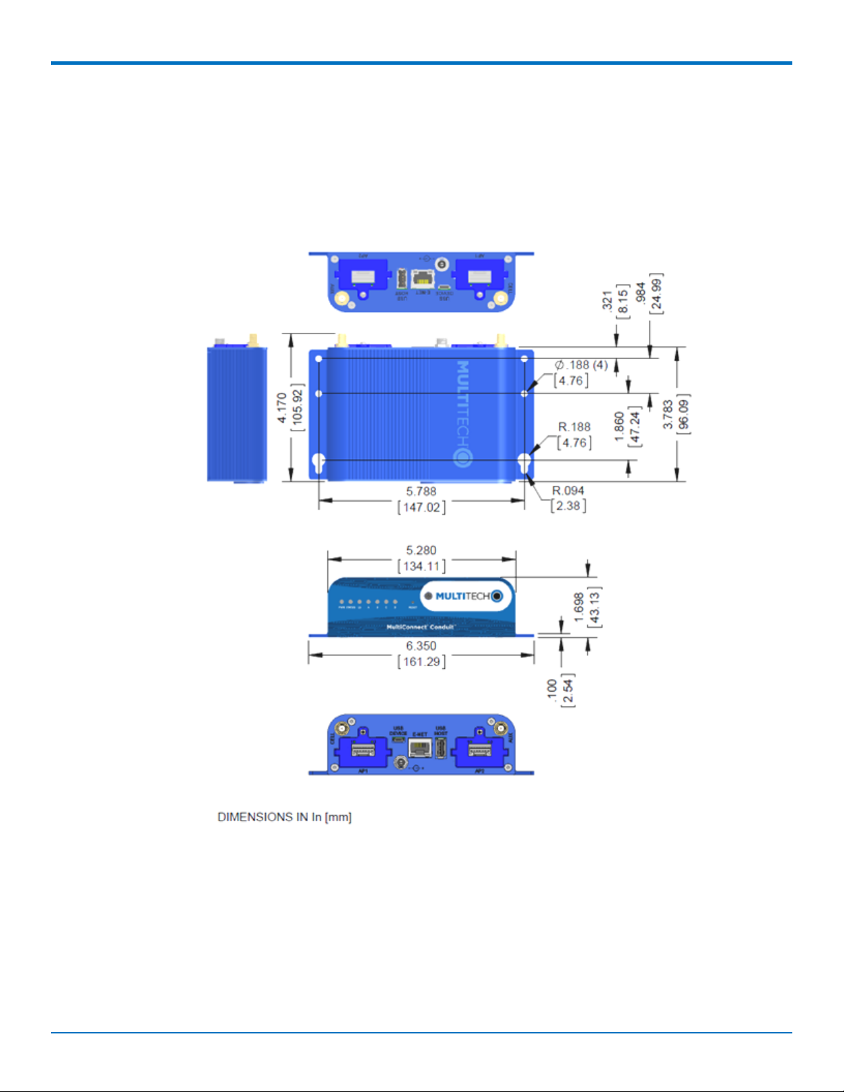
Dimensions See the Conduit Demensions Drawing
Weight 15.6 oz. (442.25 grams) with no accessory cards installed
Connectors
Connectors 1 USB device micro Type B debug port (behind nameplate)
1 RJ-45 Ethernet port
1 USB micro port
2 cellular antenna connectors
1 Wi-Fi/Bluetooth connector
1 GPS antenna connector
Power Requirements
Input Voltage 9-32 Volts
Power Draw See Conduit Power Draw
Environment
Operating Environment -30° to +70° C
Storage Environment -40° to +85° C
Relative Humidity 20 to 90% non-condensing
Certifications
Radio & EMC Compliance EN 55022:2010
EN 301 489
FCC Part 15 Class B
IC Class B
Safety Compliance UL/cUL 60950-1 2nd Ed.
IEC 60950-1 2nd Ed. Am. 1 and Am. 2
Telecom Approvals Based on radio installed
1
1
UL Listed @ 40° C, limited by AC power supply. UL Recognized @ 65° C for Conduit LTE devices within IP67
enclosure or when used with the fused DC power cable, part number FPC-532-DC.
Installation in outdoor locations or ambient above 70° C has not been evaluated by UL. UL Certification does not
apply or extend to use in outdoor applications.
8 MultiConnect®ConduitTMHardware Guide
Page 9
SPECIFICATIONS
Optional power must be UL Listed ITE power supply marked LPS or Class 2 rated 12 VDC, 5A. Certification does not
apply or extend to Voltages outside certified range, and has not been evaluated by UL for operating voltages
beyond tested range.
Mechanical Drawing
MultiConnect®ConduitTMHardware Guide 9
Page 10

SPECIFICATIONS
Backpanel Connectors
Label Description
CELL, AUX Cellular antenna inputs.
H5: CELL - Primary. AUX - Diversity.
AP1, AP2 Slots for MultiTech accessory cards. You can install an accessory card in either slot. Both slots
can be occupied at one time. An exception is an SDIO (Secure Digital Input/Output) card,
which can be used only in the AP1 slot.
USB DEVICE User-defined, high-speed 480 Mbps, standard USB 2.0 Micro B connector. Use this port to
connect the Conduit to a computer or another device. By default, this port is a serial port
terminal interface, but you can program it to act as another device such as a mass storage
device or an Ethernet port.
E-NET RJ-45 receptacle for standard Ethernet 10/100 Base-T.
Caution: Ethernet ports and command ports are not designed to be connected to a public
telecommunication network or used outside the building or campus.
USB HOST High-speed, standard USB 2.0 Type A connector. 500mA maximum current draw. You can
plug into the Host port a device such as a flash drive, camera, or printer if the Linux kernel
has the appropriate driver.
Power 9-32 Vdc power receptacle for provided power cord.
10 MultiConnect®ConduitTMHardware Guide
Page 11

LED Descriptions
SPECIFICATIONS
Conduit mLinux Model Front Panel
Conduit Application Model Front Panel
Label Name Description
PWR Power Solid (constant) green if unit is on indicating that DC power is present.
STATUS Power Status Default condition: LED blinks when mLinux is fully loaded.
LS Link Status Varies with radio model.
A-B-C-D -- These 4 LEDs are user-specified. Present on the Conduit mLinux model only.
CD Carrier Detect This LED is on when a cellular data connection is made. Present on the
Conduit Application model only.
Signal Signal Strength These 3 LEDs display the strength of the cellular signal. Present on the
Conduit Application model only.
If a cellular radio such as EV3, H5, LAT1, LVW2, LAT3, LVW3, LNA3, or LDC3, is installed, the typical LS (Link Status)
LED behavior is the following:
OFF - No power to the cellular radio
Continuously Lit - Not registered
Slow Blink (-0.2Hz) - Registered or connected
MultiConnect®ConduitTMHardware Guide 11
Page 12

SPECIFICATIONS
On the back of the Conduit, the RJ-45 Ethernet LEDs (located at the bottom of the connector) are defined as
follows:
Orange LED (lower-left) indicated activity/link. Blinks when there is transmit and receive on the
Ethernet link. It shows a steady light when there is a valid Ethernet connection.
Green LED (lower-right) indicates link speed. Lit when Ethernet is linked at 100Mbps. If not lit, Ethernet
is linked at 10 Mbps.
12 MultiConnect®ConduitTMHardware Guide
Page 13

Chapter 3 – Power Draw
MTCDT-H5-246 with Modem and No Accessory Cards Power Draw
POWER DRAW
Radio Protocol Idle Cellular
Connection no
data (Amps)
Average Tx
Current at Max
Power passing
Peak Tx Current
(Amps)
1
Total Inrush
Charge (mC)
2
Charge Duration
(mS)
Total Inrush
data (Amps)
9.0 Volts
GSM 850 MHz 0.182 0.342 1.12 (pulse avg.) 5.18 9.60
HSDPA 0.208 0.472 0.548 5.18 9.60
12.0 Volts
GSM 850 MHz 0.148 0.268 0.826 4.59 8.58
HSDPA 0.151 0.391 0.460 4.59 8.58
24.0 volts
GSM 850 MHz 0.099 0.161 0.455 3.68 17.55
HSDPA 0.101 0.214 0.288 3.68 17.55
1
Peak Tx Current: The average peak current during a GSM850 transmission burst period or HSDPA connection. The
transmission burst duration for GSM850 can vary, depending on what transmission scheme is being deployed
(GPRS Class 8, Class 10, GSM, etc.).
2
Total Inrush Charge: The total inrush charge at power on expressed in Millicoulombs (mC).
Note:
Multi-Tech Systems, Inc. recommends that you incorporate a 10% buffer into the power source when
determining product load.
MTCDT-LEU1-246 with Modem and No Accessory Cards
Radio Protocol Idle Cellular
Connection no
data (Amps)
9.0 Volts
EGSM 900 MHz 0.178 0.363 1.10 4.87 9.7
LTE 0.192 0.552 0.632 4.87 9.7
12.0 Volts
EGSM 900 MHz 0.140 0.290 0.835 4.2 8.5
LTE 0.151 0.440 0.512 4.2 8.5
24.0 Volts
EGSM 900 MHz 0.093 0.170 0.441 3.65 17.9
Average Tx
Current at Max
Power Passing
Data (Amps)
1
Peak Tx Current
(Amps)
2
Total Inrush
Charge (mC)
3
Charge Duration
(mS)
Total Inrush
MultiConnect®ConduitTMHardware Guide 13
Page 14

POWER DRAW
Radio Protocol Idle Cellular
Connection no
data (Amps)
Average Tx
Current at Max
Power Passing
Data (Amps)
1
Peak Tx Current
(Amps)
2
Total Inrush
Charge (mC)
3
Charge Duration
(mS)
Total Inrush
LTE 0.102 0.249 0.316 3.65 17.9
1
Max Power: The continuous current during maximum data rate with the radio transmitter at maximum power.
2
Peak Tx Current: The average peak current during an EGSM900 transmission burst period or LTE connection. The
transmission burst duration for EGSM900 can vary, depending on what transmission scheme is being deployed
(GPRS Class 8, Class 10, GSM, etc.).
3
Total Inrush Charge: The total inrush charge at power on expressed in Millicoulombs (mC).
Note:
Multi-Tech Systems, Inc. recommends that you incorporate a 10% buffer into the power source when
determining product load.
MTCDT-LVW2-246 with Modem and No Accessory Cards
Radio Protocol Idle Cellular
Connectionno
data (Amps)
Average Tx
Current at Max
Power Passing
Data (Amps)
1
Peak Tx Current
(Amps)
2
Total Inrush
Charge (mC)
3
Charge Duration
(mS)
Total Inrush
9.0 Volts
LTE 0.175 0.482 0.556 4.87 9.7
12.0 Volts
LTE 0.148 0.375 0.499 4.2 8.5
24.0 Volts
LTE 0.100 0.214 0.303 3.65 17.9
1
Max Power: The continuous current during maximum data rate with the radio transmitter at maximum power.
2
Peak Tx Current: The average peak current during LTE connection.
3
Total Inrush Charge: The total inrush charge at power on expressed in Millicoulombs (mC).
Note:
Multi-Tech Systems, Inc. recommends that you incorporate a 10% buffer into the power source when
determining product load.
MTCDT-246A No Modem and No Accessory Cards
Voltage No Connections
(Amps)
1
Ethernet
Connected only
(Amps)
2
Maximum
Current (Amps)
Total Inrush
3
Charge (mC)
4
Charge Duration
(mS)
Total Inrush
9.0 Volts 0.147 0.155 0.222 3.92 9.7
12.0 Volts 0.124 0.128 0.175 3.26 8.54
14 MultiConnect®ConduitTMHardware Guide
Page 15

POWER DRAW
Voltage No Connections
(Amps)
1
Ethernet
Connected only
(Amps)
2
Maximum
Current (Amps)
Total Inrush
3
Charge (mC)
4
Charge Duration
(mS)
Total Inrush
24.0 Volts 0.081 0.086 0.114 2.48 14.6
1
No Connections: Typical measure performed with the unit powered up only–no connections to the device.
2
Ethernet Connected Only: Typical power with Ethernet measured and the device attached to PC with Ethernet
cable only.
3
Maximum Current: Maximum current measured with Ethernet connected, SD Card, and USB Device actively
running read/write script, USB Debug and Host active running find/command.
4
Total Inrush Charge: The total inrush charge at power on expressed in Millicoulombs (mC).
Note:
Multi-Tech Systems, Inc. recommends that you incorporate a 10% buffer into the power source when
determining product load.
MultiConnect®ConduitTMHardware Guide 15
Page 16

POWER DRAW
MTCDT-210 with Modem and no Accessory Cards Power Draw
Radio Protocol Idle Cellular
Connectionno
data (Amps)
Average Tx
Current at Max
Power passing
Peak Tx Current
(Amps)
1
Total Inrush
Charge (mC)
2
Charge Duration
(mS)
Total Inrush
data (Amps)
9.0 Volts
GSM 850 MHz 0.200 0.400 1.200 (pulse avg.) 5.21 8.27
HSDPA 0.198 0.525 0.616 5.21 8.27
12.0 Volts
GSM 850 MHz 0.166 0.323 0.884 4.81 8.26
HSDPA 0.168 0.453 0.540 4.81 8.26
24.0 Volts
GSM 850 MHz 0.099 0.175 0.490 3.99 20.0
HSDPA 0.101 0.245 0.320 3.99 20.0
1
Peak Tx Current: The average peak current during a GSM 850 transmission burst period or HSDPA connection. The
transmission burst duration for GSM 850 can very, depending on what transmission scheme is being deployed
(GPRS Class 8, Class 10, GSM, etc.).
2
Total Inrush Charge: The total inrush charge at power on expressed in Millicoulombs (mC).
Note: Multi-Tech Systems, Inc. recommends that you incorporate a 10% buffer into the power source when
determining product load.
MTCDT-LEU1-210 with Modem and no Accessory Cards Power Draw
Radio Protocol Idle cellular
Connection no
data (Amps)
9.0 Volts
EGSM 900 MHz 0.242 0.435 1.33 5.21 8.27
LTE 0.256 0.615 0.704 5.21 8.27
12.0
EGSM 900 MHz 0.192 0.340 0.931 4.81 8.26
LTE 0.203 0.468 0.512 4.81 8.26
24.0 Volts
EGSM 900 MHz 0.104 0.189 0.493 3.99 20.0
LTE 0.115 0.245 0.312 3.99 20.0
1
Max Power: The continuous current during maximum data rate with the radio transmitter at maximum power.
Average Tx
Current at Max
Power Passing
Data (Amps)
1
Peak Tx Current
(Amps)
2
Total Inrush
Charge (mC)
3
Charge Duration
(mS)
Total Inrush
16 MultiConnect®ConduitTMHardware Guide
Page 17

POWER DRAW
2
Peak Tx Current: The average peak current during an EGSM 900 transmission burst period or LTE connection. The
transmission burst duration for EGSM 900 can very, depending on what transmission scheme is being deployed
(GPRS Class 8, Class 10, GSM, etc.).
3
Total Inrush Charge: The total inrush charge at power on expressed in Millicoulombs (mC).
Note: Multi-Tech Systems, Inc. recommends that you incorporate a 10% buffer into the power source when
determining product load.
MTCDT- LAT1-210 with Modem and No Accessory Cards
Radio Protocol Idle Cellular
Connection no
data (Amps)
Average Tx
Current at Max
Power Passing
Data (Amps)
1
Peak Tx Current
(Amps)
2
Total Inrush
Charge (mC)
3
Charge Duration
(mS)
Total Inrush
9.0 Volts
GSM 850 MHz 0.200 0.436 1.20 6.4 8.50
LTE 0.201 0.525 0.588 6.4 8.50
12.0 Volts
GSM 850 MHz 0.163 0.335 0.915 5.18 8.2
LTE 0.164 0.410 0.480 5.18 8.2
24.0 Volts
GSM 850 MHz 0.094 0.186 0.440 4.12 11.8
LTE 0.095 0.225 0.300 4.12 11.8
1
Max Power: The continuous current during maximum data rate with the radio transmitter at maximum power.
2
Peak Tx Current: The average peak current during an GSM 850 transmission burst period or LTE connection. The
transmission burst duration for GSM 8502 can very, depending on what transmission scheme is being deployed
(GPRS Class 8, Class 10, GSM, stc.).
3
Total Inrush Charge: The total inrush charge at power on expressed in Millicoulombs (mC).
Note: Multi-Tech Systems, Inc. recommends that you incorporate a 10% buffer into the power source when
determining product load.
MTCDT-LVW2-210 with Modem and No Accessory Cards
Radio Protocol Idle Cellular
Connection no
data (Amps)
9.0 Volts
LTE 0.205 0.550 0.620 6.28 8.28
12.0 Volts
LTE 0.161 0.414 0.500 5.15 8.43
MultiConnect®ConduitTMHardware Guide 17
Average Tx
Current at Max
Power Passing
Data (Amps)
1
Peak Tx Current
(Amps)
2
Total Inrush
Charge (mC)
3
Charge Duration
(mS)
Total Inrush
Page 18

POWER DRAW
Radio Protocol Idle Cellular
Connection no
data (Amps)
Average Tx
Current at Max
Power Passing
Data (Amps)
1
Peak Tx Current
(Amps)
2
Total Inrush
Charge (mC)
3
Charge Duration
(mS)
Total Inrush
24.0 Volts
LTE 0.096 0.227 0.300 2.75 7.43
1
Max Power: The continuous current during maximum data rate with the radio transmitter at maximum power.
2
Peak Tx Current: The average peak current during LTE connection.
3
Total Inrush Charge: The total inrush charge at power on expressed in Millicoulombs (mC).
Note: Multi-Tech Systems, Inc. recommends that you incorporate a 10% buffer into the power source when
determining product load.
MTCDT-210 No Modem and No Accessory Cards
Voltage No Connections
(Amps)
1
9.0 Volts 0.151 0.168 0.265 2.37 1.05
12.0 Volts 0.130 0.139 0.204 3.4 8.24
Ethernet
Connected only
(Amps)
2
Maximum
Current (Amps)
Total Inrush
3
Charge (mC)
4
Charge Duration
(mS)
Total Inrush
24.0 Volts 0.080 0.086 0.114 2.8 22.7
1
No Connections: Typical measure performed with the unit powered up only–no connections to the device.
2
Ethernet Connected Only: Typical power with Ethernet measured and the device attached to PC with Ethernet
cable only.
3
Maximum Current: Maximum current measured with Ethernet connected, SD Card, and USB Device actively
running read/write script, USB Debug and Host active running find/command.
4
Total Inrush Charge: The total inrush charge at power on expressed in Millicoulombs (mC).
Note: Multi-Tech Systems, Inc. recommends that you incorporate a 10% buffer into the power source when
determining product load
18 MultiConnect®ConduitTMHardware Guide
Page 19

POWER DRAW
MTCDT-LEU1-247 with Bluetooth, Wi-Fi, and No Accessory Cards Power Draw
Radio Protocol Idle Cellular Call
Box Connection
No Data
Average
Measured
Current at Max
Power (Wi-Fi
WAN Active
Internet
TX Pulse (AVG)
Amplitude
Current for
GSM850 or Peak
Current for
HSDPA/LTE
2
Total Inrush
Charge
Measured
3
Total Inrush
Charge Duration
During Powerup
(Inrush Duration)
Upload/Downloa
1
d)
9.0 Volts
EGSM 900 MHz 283 mA 635 mA 1.30 Amps 4.87 mC 9.7 mS
LTE 296 mA 850 mA 952 mA 4.87 mC 9.7 mS
12.0 Volts
EGSM 900 MHz 220 mA 490 mA 928 mA 4.2 mC 8.5 mS
LTE 232 mA 675 mA 748 mA 4.2 mC 8.5 mS
24.0 Volts
EGSM 900 MHz 124 mA 258 mA 385 mA 3.65 mC 17.9 mS
LTE 131 mA 343 mA 420 mA 3.65 mC 17.9 mS
1
Maximum Power: The continuous current during maximum data rate with the radio transmitter at maximum
power.
2
Peak Tx Current: The average peak current during a GSM850 transmission burst period or HSDPA connection. The
transmission duration for GSM850 can vary, depending on what transmission scheme is being deployed (GPRS
Class 8, Class 10, GSM, etc.).
3
Total Inrush Charge: The total inrush charge at power.
Note: Multi-Tech Systems, Inc. recommends that you incorporate a 10% buffer into the power source when
determining product load.
MultiConnect®ConduitTMHardware Guide 19
Page 20

FREQUENCY INFORMATION
Chapter 4 – Frequency Information
Frequency Bands for Conduit
Cellular Radio Frequencies
LE910-Eug
LEU1
LE910-NAG
LAT1
LE910-SVG
LVW2
HE910-D
H5
2G 900/1800, 3G 850/900/2100, LTE/FDD
800/1800/2600
2G 850/1900, WCDMA 850/1900, LTE/FDD
700/850, AWS 1700/1900
700
AWS 1700
GSM 850/900, DCS 1800, PCS 1900, WCDMA
800/850/900, AWS 1700/1900/2100
Frequency and Power Information for WiFi/Bluetooth
Operating Frequency RF Output Power
802.11b: 2400 MHz – 2483.5 MHz 19.1 dBm
802.11g: 2400 MHz – 2483.5 MHz 19.9 dBm
802.11n: 2400 MHz – 2483.5 MHz 19.9 dBm
802.11a: 5150 MHz – 5350 MHz, 5470 MHz – 5725 MHz 13.5 dBm
802.11n: 5150 MHz – 5350 MHz, 5470 MHz – 5725 MHz 13.6 dBm
BT/BLE: 2400 MHz – 2483.5 MHz 10.1 dBm
Frequency and Power Information for LoRa
Operating Frequency RF Output Power
FCC Part 15C: 923.3 MHz – 927.5 MHz (USA) 25.1 dBm
EN 300 220-2: 863.1 MHz – 869.9 MHz (Europe) 14 dBm
Max Radio Frequency Power for Conduit
HE910 Telit Transmission Output Power
Band Power Class
GSM 850/900 4 (2W)
DCS 1800/PCS 1900 1 (1W)
20 MultiConnect®ConduitTMHardware Guide
Page 21

Band Power Class
EDGE, 850/900 MHz E2 (0.5W)
EDGE, 1800/1900 MHz Class E2 (0.4W)
WCDMA 850/900, AWS 1700, 1900/2100 MHz Class 3 (0.25W)
LE910 Telit Transmission Output Power
Band Power Class
GSM 850/900 4 (2W)
DCS 1800/PCS 1900 1 (1W)
EDGE, 850/900 MHz E2 (0.5W)
EDGE, 1800/1900 MHz Class E2 (0.4W)
WCDMA FDD B1, B2, B4, B5, B8 Class 3 (0.25W)
LTE FDD B2, B3, B4, B5, B7, B13, B17, B20 Class 3 (0.2W)
FREQUENCY INFORMATION
MultiConnect®ConduitTMHardware Guide 21
Page 22

SETTING UP AND CONFIGURING THE DEVICE
Chapter 5 – Setting up and Configuring the Device
Install and Connect Conduit Hardware
To install and cable the device:
1. Install a Mini SIM card.
2. Install a Micro SD card (optional).
3. Install a battery (optional).
4. Connect the supplied antenna to the CELL connector on the back of the device.
5. Use the Ethernet connector to connect the Conduit to the device used to administer the Conduit.
6. Install any mCard accessory cards into a slot at the back of the device. Refer to Installing an mCard
Accessory Card for instructions.
7. Depending on the accessory card type, attach any antennas or cables for use with the card.
8. Connect the power cord to an outlet or power strip and to the power adapter.
9. Connect the power adapter to the barrel jack on the back panel of the device. The Power LED comes on
immediately after power is applied. Wait for the Status LED to begin blinking.
Installing a Mini SIM Card
You need:
Phillips screwdriver
Mini SIM card (2FF form factor)
To install or replace the SIM card:
1. Disconnect power to the Conduit, if it is connected.
2. At the front of the Conduit housing, remove the screw that secures the nameplate to the housing and
remove the nameplate.
3. Locate the SIM card holder in the upper right corner of the opening. If a SIM card is installed and needs to
be removed, slide it out of the SIM card holder.
4. Gently push the new SIM card into SIM card holder face up with the cut corner to the right and the SIM
contacts facing toward the Conduit’s interior.
5. If not installing a battery or micro SD card, reattach the MultiTech nameplate to the Conduit using the
screw removed in Step 2.
22 MultiConnect®ConduitTMHardware Guide
Page 23

SETTING UP AND CONFIGURING THE DEVICE
Accessory Port (mCard) Interfaces
The accessory card interface on the Conduit base board has the following interface options:
Interface Description
I2C Used by all accessory cards. I2C is required for
Electronic Identification (EID) support on the accessory
card but can be used for other I2C devices. It should
supports standard (100 kHz) and/or fast (400 kHz) clock
speeds.
The I2C interface reserves the full block of EEPROM
address space for Electronic ID support, so we
recommend that you not attach any other EEPROM
devices to the interface. We recommend that you use a
24C04 part, because both address bits of the 24C04 are
connected to the AP interface allowing you to identify
four separate accessory port (AP) cards in a system.
Serial UART Serial UART with HW flow control used by Serial
inteface based Accessory Cards
SDIO interface and/or SPI Interface AP1 has option for SDIO or SPI interface, based on what
Accessory Card is installed. AP2 supports only SPI based
Accessory Cards.
GPIO Additional control pins for certain Accessory Cards.
Interrupts Software defined interrupts. Can also be used as
additional control pins.
MultiConnect®ConduitTMHardware Guide 23
Page 24

SETTING UP AND CONFIGURING THE DEVICE
Interface Description
PPS GPS generated Pulse-Per-Second signal used for
software timing. Default is 1 pulse/sec.
USB 2.0 A standard USB 2.0 High Speed interface for USB based
Accessory Cards.
5 VDC 1 Amp supply Used by all accessory cards.
3.3 VDC 1 Amp supply Used by all accessory cards.
For accessory card specifications, regulatory content, and installation information, see the Accessory Card
information.
Installing a Micro SD Card
You need:
Phillips screwdriver
MicroSD memory card
To install or replace the SD card:
1. Disconnect power to the Conduit, if it is connected.
2. At the front of the Conduit, remove the screw that secures the MultiTech nameplate.
3. Locate the SD card at the left side of the opening on the underside of the PC board.
4. If an SD card is already installed, gently push on the card to release it from its setting and remove it from
the housing with your fingers.
5. With the new SD card contacts facing up and toward the interior of the device, gently push the card into
the slot to secure it.
6. Reattach the MultiTech nameplate to the housing using the screw removed in step 2.
24 MultiConnect®ConduitTMHardware Guide
Page 25

SETTING UP AND CONFIGURING THE DEVICE
Installing a Battery
The battery is located in the Conduit housing.
You need:
Phillips screwdriver
If replacing a battery, non-metal tweezers or similar object
CR1632 standard coin lithium battery
To install or replace the battery:
1. If connected, disconnect power to the Conduit.
2. At the front of the Conduit housing, remove the screw that secures the MultiTech nameplate to the
housing.
3. The battery holder is located at the right side of the opening on the underside of the PC board. To
remove an existing battery, use non-metal tweezers as necessary.
4. Orient the new battery so that the positive (+) pole is facing down. Use your fingers or non-metal
tweezers to insert the battery into the holder.
5. Reattach the MultiTech nameplate to the housing using the screw removed in Step 2.
MultiConnect®ConduitTMHardware Guide 25
Page 26

SETTING UP AND CONFIGURING THE DEVICE
CAUTION: Risk of explosion if this battery is replaced by an incorrect type. Dispose of batteries according to
instructions.
Note:
ATTENTION: Risque d’explosion si vous remplacez la batterie par un modèle incompatible. Jetez
les piles usagées selon les instructions.
Connecting to the Debug Interface
You need:
Phillips screwdriver
Standard USB Micro B cable
To connect the debug cable:
1. Disconnect power to the Conduit, if it is connected.
2. At the front of the Conduit housing, remove the screw that secures the MultiTech nameplate to the
housing.
3. Locate the USB debug cable connector in the center of the opening.
4. Connect the USB Micro B cable to the debug connector.
5. Connect the Type A end of the USB cable to the host.
6. From the host, use an application such as TeraTerm with a baud rate of 115,200. If the USB driver does
not automatically install, do the following:
a. Unplug the USB cable.
b. Go to the following web site to download and install the appropriate USB driver:
https://www.exar.com/connectivity/uart-and-bridging-solutions/usb-uarts/xr21b1411/
c. Plug the USB cable back into the housing.
7. From the host, access the Conduit's USB COM port.
26 MultiConnect®ConduitTMHardware Guide
Page 27

Restoring User Defined Settings
SETTING UP AND CONFIGURING THE DEVICE
You need:
A pin, paperclip, or similar thin object that can fit into the reset hole.
To restore user defined settings for an AEP device:
1. Locate the hole in the panel labeled RESET. The reset button is recessed into the housing.
2. Use the pin to press in the button for between 3 to 29 seconds, then release the reset button.
If you do not press in the button long enough, the device will reset, but the user defined settings will
not be restored.
If you hold it too long (30 seconds or longer), factory default settings will be restored.
Note: The RESET button is in the same location on all Conduit models.
Resetting the Device
You need:
A pin, paperclip, or similar thin object that can fit into the reset hole.
The following is the default condition for the RESET button on the Conduit. You can program a change to the
behavior of the button if needed.
To reset the device:
1. Find the hole in the front panel labeled RESET. The reset button is recessed into the case.
2. For AEP: Use the pin to press the RESET button for less than 3 seconds, then release. The device reboots.
For mLinux: Press and hold the RESET button for less than 5 seconds, then release. Holding it beyond 5
seconds resets an mLinux device to factory defaults.
3. The status LED will keep blinking normally for a couple of seconds until the unit resets. Then the status
light will stay solid while the device reboots. Once finished, the status will resume blinking normally.
MultiConnect®ConduitTMHardware Guide 27
Page 28

SETTING UP AND CONFIGURING THE DEVICE
Powering Up the device
CAUTION: Use only the power cord provided with the device. Using any other power cord voids the warranty
and can damage the device.
To power up the device:
1. Install the desired MultiTech accessory card or cards into the slots at the back of the device. Refer to the
appropriate installation documentation for the accessory card.
2. Connect the power cord to an outlet or power strip and to the power adapter.
3. Connect the power adapter to the barrel jack on the back panel of the device.
4. Verify power.
The Power LED comes on immediately after power is applied.
The device takes a short time to boot up when you apply power.
5. Connect the device to the controlling device through the Ethernet connector or the USB connector on the
back panel.
28 MultiConnect®ConduitTMHardware Guide
Page 29

REGULATORY INFORMATION
Chapter 6 – Regulatory Information
Conduit Regulatory Information
For regulatory infomration please see http://www.multitech.net/developer/products/multiconnect-conduit-
platform/conduit/conduit-regulatory-information/
MultiConnect®ConduitTMHardware Guide 29
 Loading...