

Page 1
MA30120
User Guide
Page 2

User Guide
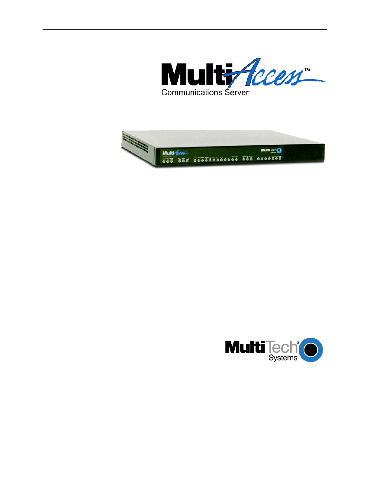
MultiAccess Communications Server
MultiAccess
S000255E Revision E
All rights reserved. This publication may not be reproduced, in whole or in part, without prior expressed
written permission from Multi-Tech Systems, Inc.
Copyright © 2012 by Multi-Tech Systems, Inc.
Multi-Tech Systems, Inc. makes no representations or warranty with respect to the contents hereof and
specifically disclaims any implied warranties of merchantability or fitness for any particular purpose.
Furthermore, Multi-Tech Systems, Inc. reserves the right to revise this publication and to make changes
from time to time in the content hereof without obligation of Multi-Tech Systems, Inc. to notify any person
or organization of such revisions or changes.
Record of Revisions
Revision Date Description
A 11/17/03 Manual released.
B 12/06/04 Manual revised to include an appendix on modem commands and
version 1.08 of the MultiAccess software.
C 07/05/05 Manual revised to include software release version 1.12.
D 10/04/06 Manual revised to update AT Commands in Appendix B and includes
software version 1.14.
E 09/18/12 Updated RoHS.
Patents
This device covered by one or more of the following patents: 6,031,867; 6,012,113; 6,009,082; 5,864,560;
5,815,503; 5,812,534; 5,790,532; 5,764,628; 5,764,627; 5,754,589; 5,724,356; 5,673,268; 5,673,257;
5,628,030; 5,619,508; 5,617,423; 5,600,649; 5,592,586; 5,577,041; 5,574,725; 5,559,793; 5,546,448;
5,546,395; 5,535,204; 5,500,859; 5,471,470; 5,463,616; 5,453,986; 5,452,289; 5,450,425; 5,309,562;
5,301,274
Trademarks
Trademarks of Multi-Tech Systems, Inc.: Multi-Tech, and Multi-Tech logo.
HylaFAX is a trademark of Silicon Graphics Corporation. Windows is a registered trademark of Microsoft
Corporation in the United States and other countries.
All products or technologies are the trademarks or registered trademarks of their respective holders.
Technical Support
Country By Email By Phone
France: support@multitech.fr +(33) 1-64 61 09 81
India: support@multitechindia.com +91 (124) 2340780
Europe, Asia, Africa: support@multitech.co.uk +(44) 118 959 7774
U.S., Canada, all others: support@multitech.com (800) 972-2439 or +763-717-5863
World Headquarters
Multi-Tech Systems, Inc.
2205 Woodale Drive
Mounds View, Minnesota 55112
(763) 785-3500 or (800) 328-9717
Fax 763-785-9874
Internet Address: http://www.multitech.com
Page 3

Contents
Chapter 1 - Introduction and Description ................................................................................. 5
WAN Communications .......................................................................................................... 5
Managemen
Remote Access
Features ................................................................................................................................ 6
Ship Kit Contents
Front Panel
Back Panel
Typical Application
Specificat
t .......................................................................................................................... 5
..................................................................................................................... 5
................................................................................................................... 6
............................................................................................................................ 7
............................................................................................................................ 8
................................................................................................................. 9
ions ...................................................................................................................... 11
Chapter 2 - Installation
Safety Warn
Safety Reco
Site Plannin
Hardware Installation Procedure
Starting Your MultiAccess
Network Setup
Line Interfaces
Modem Set
User Authentication
Chapter 3 - Softw
Home and L
Administration ...................................................................................................................... 35
Networks & Services
Network Setup
DHCP Server
Tracking
Packet Filter
User Authentication
Modem Set
Statistics & Logs
Line Interfaces
ings .................................................................................................................. 12
mmendations for Rack Installations ................................................................. 12
g ....................................................................................................................... 13
up ...................................................................................................................... 21
are ................................................................................................................. 32
ogout Options ................................................................................................... 33
....................................................................................................................... 66
............................................................................................................................... 70
s ....................................................................................................................... 71
up ...................................................................................................................... 88
............................................................................................................. 12
......................................................................................... 14
................................................................................................... 15
..................................................................................................................... 19
..................................................................................................................... 20
............................................................................................................. 28
........................................................................................................... 50
..................................................................................................................... 56
............................................................................................................. 75
.................................................................................................................. 98
................................................................................................................... 117
Chapter 4 - Troubleshooting
Chapter 5 - MultiAcces
Chapter 6- Warranty
Regulatory Compliance
Recording MultiAccess
Appendix A - License Agreements
GENERAL PUBLIC LICENSE .................................................................................. 138
GNU
Appendix B – Modem Commands ......................................................................................... 141
“AT” Command Syntax Convention ................................................................................... 141
“AT” Commands Suppo
“AT” Commands Accept
s Maintenance .................................................................................. 130
and Service .......................................................................................... 131
.................................................................................................. 129
..................................................................................................... 133
Information ................................................................................... 135
........................................................................................ 136
rted ............................................................................................... 144
ed with No Effect ......................................................................... 147
Page 4

S-Registers ........................................................................................................................ 148
Advanced MultiAccess Modem Commands ...................................................................... 152
Application Notes
ASCII Con
version Chart .................................................................................................... 161
............................................................................................................... 159
Appendix C – How
Menu Drive
Manual Met
Appendix D – Waste Electrical and Electronic Equipment (WEEE) Sta
Appendix E – Restriction of the Use of Hazardous Substances (RoHS)
to Update ................................................................................................. 162
n: ..................................................................................................................... 162
hod (via Linux command line): ........................................................................ 162
tement ................. 165
........................... 166
Glossary ................................................................................................................................... 167
Index ......................................................................................................................................... 178
Page 5
Chapter 1 – Introduction and Description
Chapter 1 - Introduction and
Description
Welcome to Multi-Tech’s new MultiAccess Communications Server, Model MultiAccess. The MultiAccess
Communications Server is a high-performance digital remote access solution for Enterprise LANs and
Intranets or Internet service providers. MultiAccess is a V.92 remote access server (RAS) supporting up to
four T1 line interfaces implementing either RBS or PRI signaling for use in North America or up to four E1
line interfaces implementing PRI signaling for the rest of the world. The MultiAccess Communications Server
uses a web based Graphical User Interface (GUI) for configuration, is a 1U (one-up) rackmountable unit that
contains up to four universal modem ports for dial-in communications.
WAN Communications
MultiAccess ships turnkey for T1/RBS or T1/E1 PRI ISDN and populated with 30 modems on line interface 1
for the basic configuration. Additional modem modules can be added to support up to four T1/E1 line
interfaces. The high-density modems provide V.92/56K dial-up speeds. In addition, they are manageable
from remote locations using platform-independent, industry standard protocols.
Management
MultiAccess includes robust management support allowing a network administrator to securely manage the
devices either through a web browser or at the command line. The browser-based option uses the HTTPS
protocol, also know as SSL (Secure Sockets Layer) to provide 128-bit encryption to secure the management
session. The command line interface is accessible via SSH (Secure Shell) and supports SCP (Secure Copy)
and sftp (Secure File Transfer Protocol) to help provide maintenance support.
SNTP Support. MultiAccess includes an industry standard Simple Network Time Protocol (SNTP) client that
enables it to synchronize its clock with a remote time/clock server on the Internet. This feature is useful for
accounting purposes.
Remote Access
Comprehensive Security. MultiAccess provides an industry standard Radius Server and Radius Client for
authentication and authorization of thousands of user profiles using PAP and CHAP. In addition, it uses
Network Address Translation (NAT) to hide internal, non-routable IP addresses. If a Radius Server does not
exist, one is provided as part of the MultiAccess system. This Radius Server could provide authentication
and authorization information for this and other Radius Clients in use at your site.
MultiAccess Communications Server MA30120 User Guide 5
Page 6

Chapter 1 – Introduction and Description
Features
Compact design that supports up to four channelized T1 and/or IDSN PRI interfaces per rack unit
Dial-in scalability for up to 96/120 users
Terminates both analog and digital (ISDN) calls
Client authentication provided through industry standard Radius
V.92 modem-on-hold
V.92 quick connect
V.44 data compression
10/100 Mb Ethernet Lan/Wan connectivity
Simultaneous V.92/56K and 128 BRI ISDN sessions
Industry-standard PPP client support
PAP and CHAP authentication
Secure, graphical local or remote management using HTTPS or SSH
Standard 19” rackmountable chassis (1U)
Two-year warranty
Ship Kit Contents
The MultiAccess is shipped with the following:
1 MultiAccess
4 power cords (US, Euro, Austral, & UK)
1 printed Quick Start Guide
1 Document CD
1 Recovery Image CD
2 Rack Mounting Brackets and four mounting screws
If any of these items are missing, contact Multi-Tech Systems or your dealer or distributor. Inspect the
contents for signs of any shipping damage. If damage is observed, do not power up the MultiAccess. Contact
Multi-Tech’s Tech Support
for advice.
MultiAccess Communications Server MA30120 User Guide 6
Page 7
Chapter 1 – Introduction and Description
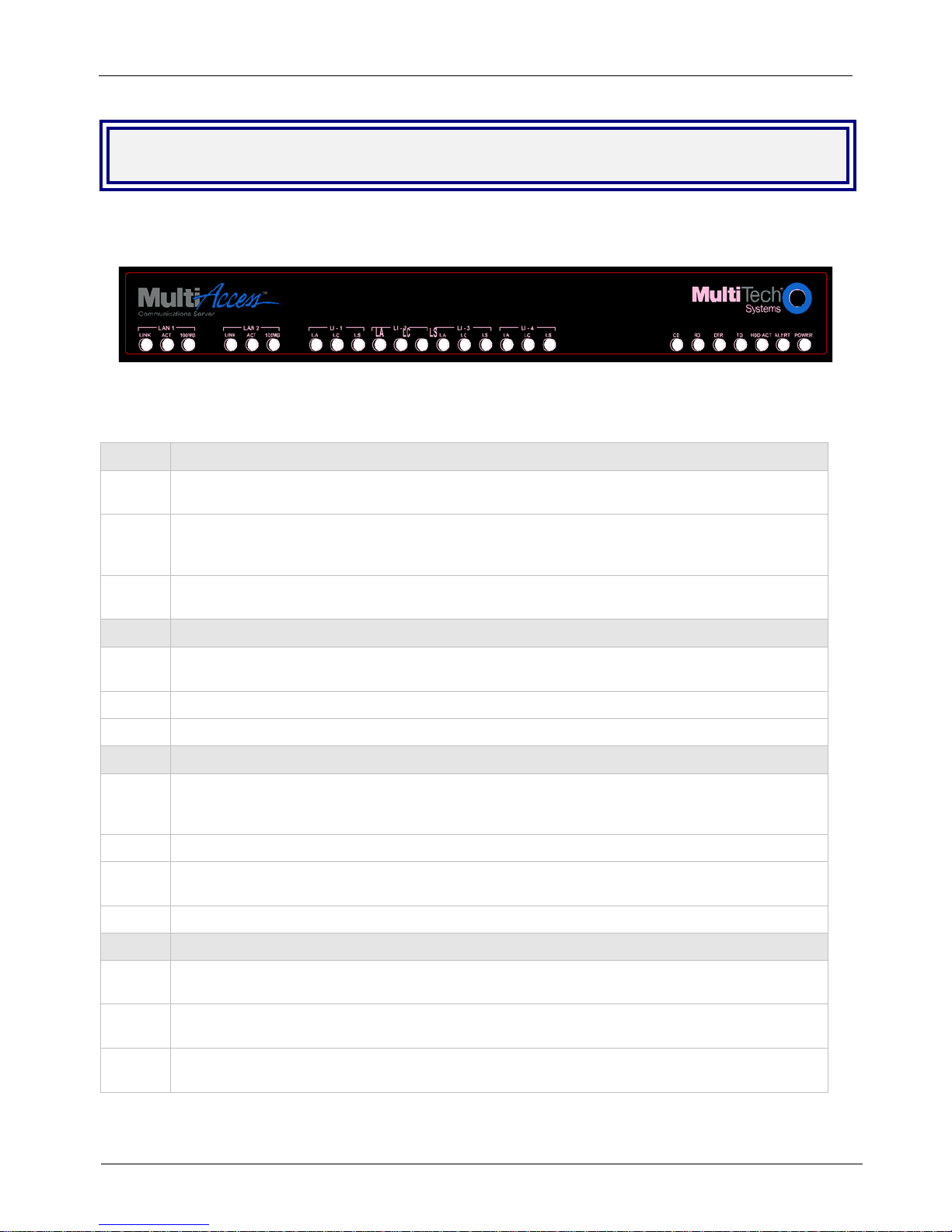
Front Panel
The front panel has 16 front panel LEDs that provide operating status.
The Front Panel
Front Panel LED Descriptions
LED Description of LAN 1 & 2 LEDs
LINK
ACT
100MB
LED Description of LIne LI-1 thru LI-4 LEDs
LA
LC
LS
LED Description of Support Modem LEDs
CD
The LINK LED indicates link integrity for the LAN Ethernet port. If the Ethernet link is valid at
either 10 Mbps or 100 Mbps, the LINK LED is lit. If the Ethernet link is invalid, the LINK LED is off.
The ACT (Activity) LED indicates either transmit or receive activity on the LAN Ethernet port.
When activity is present on the LAN Ethernet port, the ACT LED is lit. When no activity is present
on the LAN Ethernet port, the ACT LED is off.
The 100MB LED indicates the speed of the LAN Ethernet port. The 100MB LED is lit if the LAN
Ethernet port is linked at 100 Mbps. The 100 MB LED is off at 10 Mbps.
The LA (Link Active) indicates layer 1 is up. LA blinks when Los of Frame Alignment (LFA) but not
Loss of Signal (LOS).
The LC indicates a red alarm.
The LS indicates a yellow alarm.
The CD (Carrier Detect) LED lights when the modem detects a valid carrier signal from another
modem. It is on when the modem is communicating with the other modem. It is off when the link is
broken.
RD
DTR
TD
LED Description of System LEDs
HDD
ACT
ALERT
POWER
The RD (Read Data) LED flashes when the modem is receiving data from another modem.
The DTR (Data Terminal Ready) LED lights when the operating system detects and initializes the
modem.
The TD (Transmit Data) LED flashes when the modem is transmitting data to another modem.
The HDD ACT (Hard Disk Drive Activity) LED lights when the MultiAccess hard disk drive is
accessed.
The ALERT LED lights and the system beeps when memory DIMM is bad, missing, or if other
rudimentary hardware failure.
The POWER LED is off when the MultiAccess is in a reset state. When the POWER LED is lit, the
MultiAccess is not in a reset state.
MultiAccess Communications Server MA30120 User Guide 7
Page 8
Chapter 1 – Introduction and Description
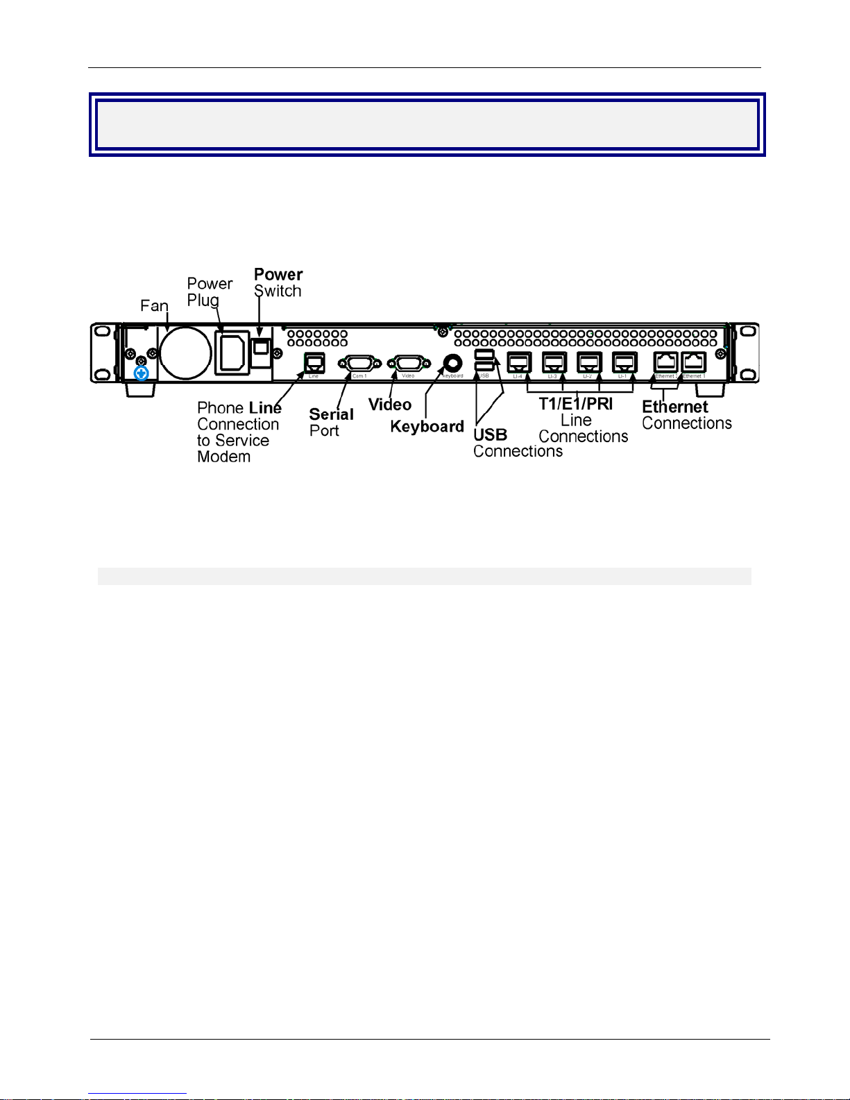
Back Panel
The MultiAccess back panel has a fan, a power plug, the POWER Switch (| / O), an RJ-11 phone LINE jack,
a DB-9 COM1 jack, a DB-15 High-density DSUB (VIDEO) jack, two USB (Revision 1.1 compliant) jacks, four
RJ-45 T1/E1/PRI line jacks, and two Ethernet RJ-45 (Ethernet 1 & Ethernet 2) jacks.
The MultiAccess back panel is illustrated and described below.
Back panel
The back panel components are described in detail in the Cabling Procedure section in Chapter 2 of this
manual.
MultiAccess Communications Server MA30120 User Guide 8
Page 9
Chapter 1 – Introduction and Description
Typical Application
Internet Service Provider (ISP) Application- Only one Ethernet interface on the MultiAccess is used.
The IP address of the MultiAccess and the pool of IP addresses for the dial-in users are of the same network
and normally are public addresses. The modems of the MultiAccess are configured for RAS usage. PPP
clients dial into the system, authenticate, via RADIUS, and establish a LAN to Client PPP session (remote
note).
MultiAccess Communications Server MA30120 User Guide 9
Page 10
Chapter 1 – Introduction and Description
Corporate Application-One or both Ethernet interfaces can be used. When both interfaces are used, they
are commonly configured with separate network addresses. The MultiAccess can provide dial-in RAS to one
or both networks and provide modem sharing and faxing for network workstations. Workstations on the
corporate LAN can be a Comm Port Redirector (e.g., Multi-Tech’s WINMCSI) for accessing MultiAccess’s
modems. Authentication can be performed before granting access to the modem sharing resource, providing
another layer of security to your network’s infrustructure.
If some or all the MultiAccess’s modems are configured for faxing, the HylaFAX server software needs to
be operating on the MultiAccess and the HylaFAX client software operating on the network workstation.
MultiAccess Communications Server MA30120 User Guide 10
Page 11

Specifications
System
LAN Ports
Server Operating
System
System Management
Security
Modem
ISDN PRI
Channelized T1
Power
Physical Description
Operating Environment
Approvals
Processor: 566 MHz Celeron
RAM: 256 MB
Number of Ports: 2 (LAN 1 and LAN 2 ports)
Interface: 2 x 10BaseT/100BaseT (UPT)
Format: Ethernet 802.3, 802.2, Ethernet II or SNAP
Linux Open Source Software
Web based (HTTPS/SSL)
Port and IP Filtering, Network Address Translation (NAT), Radius support
Analog Data Rates: V.92/56K, enhanced V.34/33.6K
ISDN Data Rates: 64K HDLC, V110 at 19.2K bps & slower
Fax Rates: 14.4K bps
Error Correction: V.42
Data Compression: V.44, MN5, and V.42bis
Fax: V.17, Group 3
Channels: 23 (T1 PRI) or 30 (E1 PRI)
B-Channel Protocols: PPP, ML-PPP, V.110
Switch Types: NI2, 4ESS, 5ESS custom, DMS100, ETSI, VN6, NTT
T1 Frame Formats: Extended Super Frame (ESF), 12 Frame Multiframe
(F12), 4 Frame Multiframe (F4), & 72 Frame Multiframe – Remote Switch
Mode (F72)
T1 Line Code: AMI or B8ZS
E1 Frame Formats: Extended Super Frame (ESF) w/ CRC4, Extended
Super Frame (ESF) w/o CRC4 (Double Fame)
E1 Line Code: AMI or HDB3
Channels: 24 DSU/CSU operation for T1 WAN service
Frame Format: Extended Super Frame (ESF), 12 Frame Multiframe (F12),
4 Frame Multiframe (F4), & 72 Frame Multiframe – Remote Switch Mode
(F72)
Line Code: AMI or B8ZS
Signaling Methods: E&M Immediate, E&M Wink, FXS ground start, FXS
loop start
Voltage & Frequency:100-240v AC, 50-60 Hz,1.2-0.6 amps universal input
Power Consumption: 30 Watts
17" w × 1.75" h × 10.5" d; 10 lbs. (1U rackmountable)
(43.18 cm × 4.45 cm × 26.67 cm; 4.54 kg)
Temperature Range: 0° to 50° C (32° to 120° F)
Humidity: relative 25-85% noncondensing
CE Mark
EMC: FCC Part 15 Class A, EN 55022, EN 55024, EN 61000-3-2,
EN 61000-3-3
Safety: UL 60950, EN 60950
Telecom: CS03, FCC Part 68, TBR4
Chapter 1 – Introduction and Description
MultiAccess Communications Server MA30120 User Guide 11
Page 12
Chapter 2 – Installation
Chapter 2 - Installation
Safety Warnings
Use this product only with UL- and CUL-listed computers.
To reduce the risk of fire, use only 26 AWG or larger telephone wiring.
Never install telephone wiring during a lightning storm.
Never install a telephone jack in a wet location unless the jack is specifically designed for wet locations.
Never touch uninsulated telephone wires or terminals unless the telephone line has been disconnected
at the network interface.
Use caution when installing or modifying telephone lines.
Avoid using a telephone during an electrical storm; there is a risk of electrical shock from lightning.
Do not use a telephone in the vicinity of a gas leak.
Caution: Danger of explosion if battery is incorrectly replaced. A lithium battery on the MultiAccess board
provides backup power for the time-keeping capability. The battery has an estimated life expectancy of ten
years. Contact Multi-Tech if you suspect a failed battery. If date and time is incorrect after having the unit
powered off, it may be due to a weak battery or incorrect setup.
Caution: The Ethernet ports are not designed to be connected to a Public Telecommunication Network.
Safety Recommendations for Rack
Installations
Ensure proper installation of the MultiAccess in a closed or multi-unit enclosure by following the
recommended installation as defined by the enclosure manufacturer. Do not place the MultiAccess
directly on top of other equipment or place other equipment directly on top of the MultiAccess.
If installing the MultiAccess in a closed or multi-unit enclosure, ensure adequate airflow within the rack so
that the maximum recommended ambient temperature is not exceeded.
Ensure that the MultiAccess is properly connected to earth ground via a grounded power cord. If a power
strip is used, ensure that the power strip provides adequate grounding of the attached apparatus.
Ensure that the main supply circuit is capable of handling the load of the MultiAccess. Refer to the power
label on the equipment for load requirements.
Maximum ambient temperature for the MultiAccess is 40 degrees Celsius (104 F).
Properly qualified service personnel should only install this equipment.
Connect like circuits. In other words, connect SELV (Secondary Extra Low Voltage) circuits to SELV
circuits and TN (Telecommunications Network) circuits to TN circuits.
MultiAccess Communications Server MA30120 User Guide 12
Page 13

Chapter 2 – Installation
Site Planning
With proper planning, your MultiAccess system can be installed quickly and in a short time. To implement the
suggested planning process, you must:
1. Plan for physical space, environmental, electronic and electrical needs. Identify physical installation site.
The environment should be properly ventilated with controlled temperature and humidity.
• Good AC power source with proper Earth Ground.
• EIA 19” rack, MultiComTower, or standalone installation.
• Determine where the termination point is for each T1, PRI, or E1 line.
• Determine physical access point to the Ethernet network.
• Identify high quality category 5 cable for Ethernet & T1 cabling. Depending on environment
characteristics, shielded T1 cable may be necessary.
• For initial setup and administrative purposes, a network workstation with a WEB browser supporting
HTTPS will be needed.
2. Define your users’ client computer needs
• Determine the number of dial in analog modem users
• Identify client workstation OS (PC running Windows98/XP/2000, or MAC OS10)
• Identify client modem types (V.34, V.90, V.92)
• Identify dial up security protocol (CHAP & PAP)
• Third-Party Security Devices (SecurID)
• Identify the Security Database (i.e. user file in RADIUS server or Microsoft SAM\Active directory with
IAS) and make sure users have dial in rights with framed protocol PPP attribute
3. Identify applicable network resources (IP address of; gateway/default route, DNS, WINS, RADIUS
server(s), etc)
• Identify the network MASK
• Identify available IP addresses (determine the static IP address that is to be assigned to the Multi
Access)
• Determine IP assignment method (predefined pool/range) to be implemented by the MultiAccess
(regarding the IP addresses to be assigned to the remote dial in users).
• When Implementing RADIUS Authentication and Accounting, identify the UDP ports used by the RADIUS
server(s)
4. Define your line interfaces
• Obtain T1 or E1 PRI line provisioning information for your LEC
• Identify the telephone number(s) of the line or lines
• Identify the Framing Format
• Identify the Line Coding
• Identify the type of signaling (RBS or PRI for T1 or E1 PRI)
• For RBS, the signaling type can be referred to as the start method and/or the FXS signaling method (i.e.
Immediate, Wink, Ground, and Loop)
• For PRI signaling identify the type of central office switch\protocol, i.e. AT&T5ESS, DMS100/250,
National ISDN2
• Identify the Line Build-Out (LBO) i.e. what db level is presented on premise by the provider and what db
level should the premise equipment transmit at.
Note: For E1 lines the signaling type must be PRI. R2 signaling methods are not supported.
MultiAccess Communications Server MA30120 User Guide 13
Page 14
Chapter 2 – Installation
Hardware Installation Procedure
The MultiAccess is designed to install either on a desktop or in a standard EIA 19“ rack, and is shipped with the
mounting hardware to install the MultiAccess in the rack. If installing in a rack, use the provided mounting
hardware and follow the rack enclosure manufacturer’s instructions to safely and securely mount the
MultiAccess in the rack enclosure. Proceed to the cabling procedure.
Cabling
Cabling your MultiAccess involves making the proper power, phone, and line (T1/E1/PRI) connections as
described and illustrated below.
The MultiAccess back panel has a fan, a power plug, POWER Switch (| / O), a RJ-11 phone LINE jack, a DB-9
COM1 jack, a DB-15 High-density DSUB (VIDEO) jack, two USB (Revision 1.1 compliant) jacks, four RJ-45
T1/E1/PRI line jacks, and two Ethernet RJ-45 (Ethernet 1 & Ethernet 2) jacks.
1. Using an RJ-45 cable, connect one end to LI-1 (Line 1 Interface) on the back of the MultiAccess and the
other end to your first T1/E1/PRI line connection. If a second, third, or fourth line connection is required,
connect an RJ-45 cable for each of the line connections being used.
2. Connect a workstation to your local network; connect one end of a RJ-45 cable to the Ethernet 1 jack on
the back of the MultiAccess and the other end to the hub on your local network.
3. For advanced users, the Video and Keyboard connections are for manual intervention of the Operating
System.
The default root level login password is linux (lower case) and the command to change the root level
password is “passwd”. The recommended mimimum password length is 8-characters. However, the
MultiAccess will accept less than 8-characters.
The Linux command to properly shut down (halt) the MultiAccess is shutdown –h now. The command to
restart is r.
4. With the MultiAccess Power switch in the off () position and using the supplied power cord, connect the
MultiAccess power plug to a live power outlet.
5. Place the MultiAccess Power switch to the on () position to turn on the MultiAccess
Caution:
Refer to Administration > System Tools in Chapter 3 of this User Guide. If the MultiAccess is not properly
shut down before switching off Power, the next start may take a little longer, or in the worst case, data could be
lost.
Never switch off MultiAccess Power until after you have performed the Shutdown process.
6. Proceed to Starting the MultiAccess.
MultiAccess Communications Server MA30120 User Guide 14
Page 15
Chapter 2 – Installation
Starting Your MultiAccess
This section covers the steps for connecting a workstation to the MultiAccess, starting up the MultiAccess,
opening the MultiAccess Communications Server Web Management program, performing the time zone setup,
and using the menu bar to navigate through the Web Management software screens.
1. Set the workstation IP address to 192.168.2.x subnet other than 192.168.2.1 which is the IP address of
Ethernet 1 (eth0) and 192.168.2.5 which is already assigned to Ethernet 2 (eht1).
2. Turn on power to the MultiAccess. When you hear 5 beeps, approximately 2 minutes after applying
power, continue with the next step.
Note: Depending on the version of MultiAccess (and other variables, like the previous shutdown and
the number of expansion modules) the duration needed to boot may vary. It may be helpful to connect
an external monitor and keyboard to determine the current status of the system. Five seconds after
turning on power, one beep is heard, indicating a successful POST of the mother board, next the BIOS
detects the hard drive from which the Linux operating system and appropriate drivers are loaded.
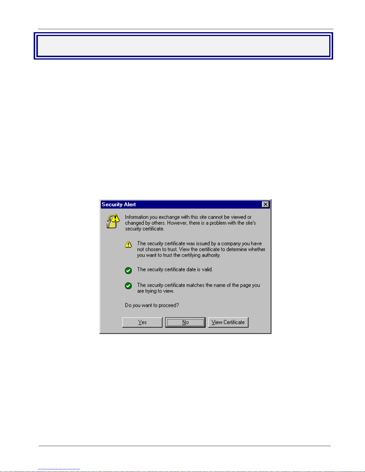
3. Bring up a Web browser on the workstation. At the browser's address line, enter https://192.168.2.1
and press the Enter key.
Important: Be sure to type https (http will not work).
4. In some environments, one or more Security Alert screen(s) may display. At the initial Security Alert
screen, click Yes and follow any additional on-screen prompts.
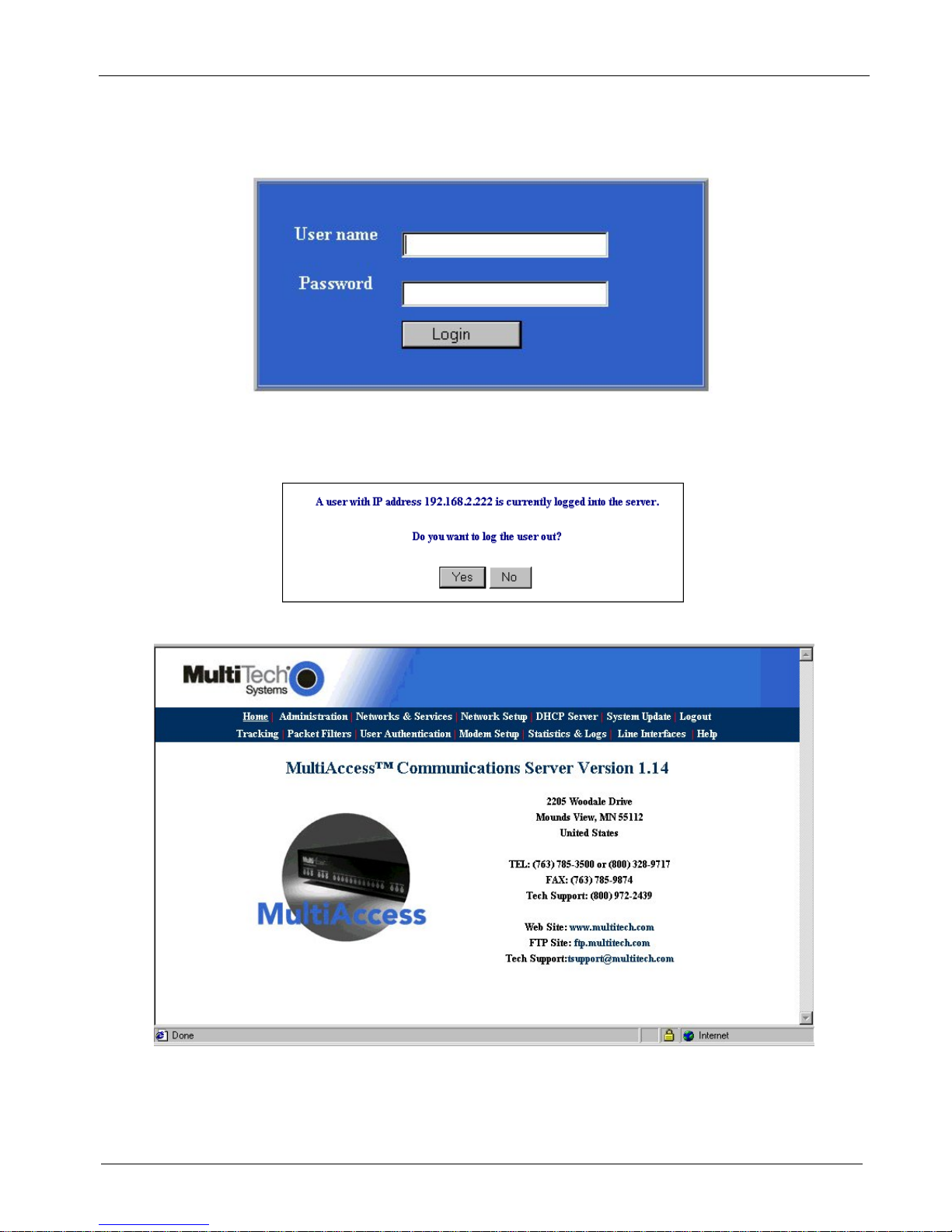
Login
1. The Login screen is displayed.
Type the default User name: admin (all lower-case)
Tab to the Password entry and type the default password: admin (all lower-case).
Click the Login button.
Note: User name and Password are case-sensitive (both must be all lower-case) and can be up to
12 characters each. Later, you will want to change the password from the default (admin) to
something else. (If Windows displays the AutoComplete screen, for security reasons, you may
want to click No to tell Windows OS to not remember the password.)
MultiAccess Communications Server MA30120 User Guide 15
Page 16
Chapter 2 – Installation
Changing the Password: You should change the default User and Password entries. This can be
accomplished in the WEB Admin screen of the Administration menu.
Caution: Use a safe password! Your first name spelled backwards is not a sufficiently safe
password; a password such as xfT35$4 is better.
2. If someone else is already logged onto the MultiAccess or you were logged in recently, the following
message displays.
At the prompt Do you want to log the user out? Click Yes. If you click No, you are returned to the
Login screen.
3. The MultiAccess Communications Server Web Management Home screen is displayed.
MultiAccess Communications Server MA30120 User Guide 16
Page 17
Chapter 2 – Installation
r
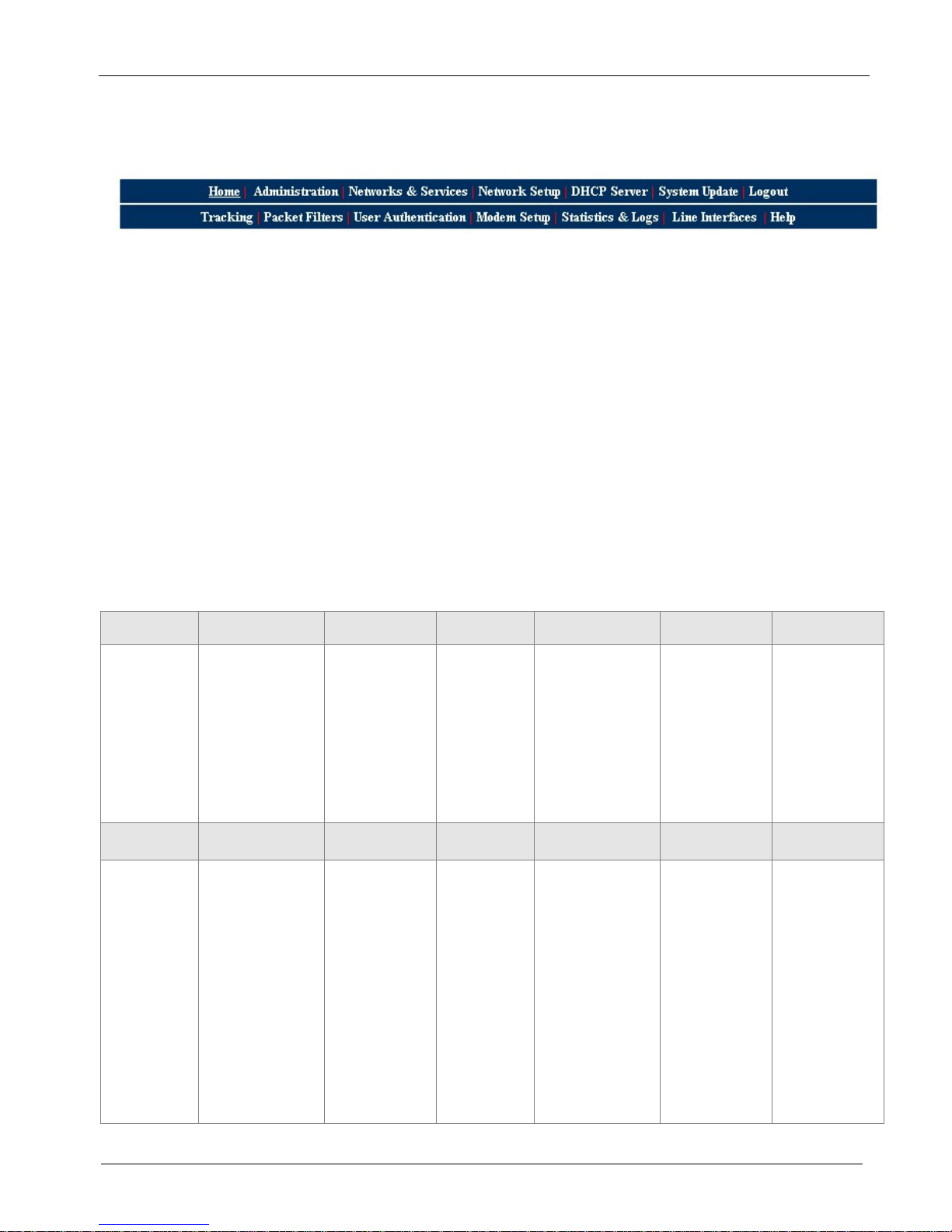
Navigating Through the Screens
When you click one of the MultiAccess Menu Bar buttons, the first screen for that function displays. Once the
first screen opens, you can navigate to other screens within this function; they are listed on the left side of the
screen.
Home: The main screen.
Administration: System setup such as Time & Date, Web management, and certificate. Provides for system
shutdown and restart, plus other administrative tools such as PING, Trace Route, and TCP Connect.
Networks & Services: Define networks, services, and groups to make them available to be used by other
functions such as allowed networks, and packet filters.
Network Setup: Set up the LAN 1, and LAN 2 Ethernet ports, etc.
DHCP Server: Configure the DHCP server settings.
System Update: Update services can be downloaded from the update server to keep your system
continually updated.
Logout: Logout and return to the login screen
Tracking: Set up tracking of all packets through the network ports in the MultiAccess.
Packet Filters: Define filter rules and ICMP rules.
User Authentication: Defines security protocol methods, passwords, and user database details.
Modem Setup: Defines the primary role of the modem; RAS, fax, or network modem pool.
Statistics & Logs: View and download all the statistics and log files maintained by your system.
Line Interfaces: Defines setup information of your PSTN lines.
Help: (Online Help) Describes what to do on each screen.
Options Under Each Menu
Home Administration Networks &
Services
Return to the
Main Menu
Tracking Packet Filters
Accounting Packet Filter Rules
System Setup
SSH
SNTP Client
Web Admin
Site Certificate
Database Setup
Backup Setup
Available Backups
Intrusion Detection
Network Tools
System Tools
Add User Defined
Filters
ICMP
Networks
Services
Network Groups
Service Groups
User
Authentication
Local Users
Radius Client
Radius Server
Network
Setup
Interface
Routes
Masquerading
SNAT
DNAT
Modem
Setup
Modem Setup
Modem Usage
Fax Setup
DHCP Serve
Subnet Settings
Fixed Addresses
Statistics &
Logs
Setup
Uptime
Networks
Interface Details,
Routing Table,
Network Connections
Line Interfaces Status
Modem Connections
Connections,
connection Details,
Caller ID, Call History
Server Connections
Interface
Accounting
Self Monitor
View Logs
System Update Logout
Available
Applied
Setup
Line
Interfaces
Line 1 Setup
Line 2 Setup
Line 3 Setup
Line 4 Setup
Exit the
Program
Help
Administration
Networks &
Services
Network Setup
DHCP Server
System Update
Tracking
Packet Filters
User
Authentication
Modem Setup
Statistics & Logs
Line Interfaces
MultiAccess Communications Server MA30120 User Guide 17
Page 18
Chapter 2 – Installation
Setup Your Time Zone
4. Click Administration on the menu bar. The System Setup screen displays.
Set the System Time by selecting your Time Zone, the current Day, Month, Year, Hour, and
Minute.
Administration
System Setup
System Time
MultiAccess Communications Server MA30120 User Guide 18
Page 19
Chapter 2 – Installation
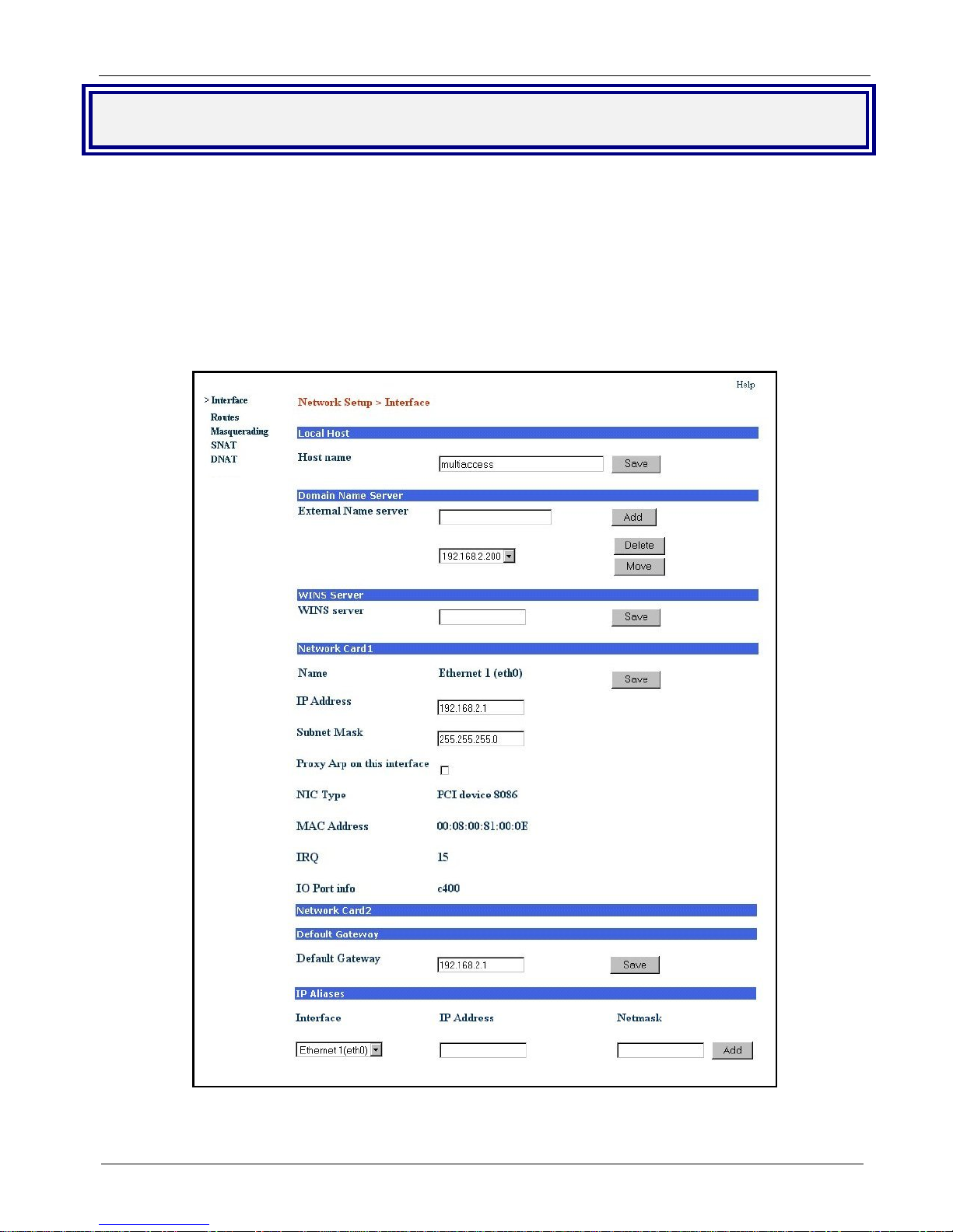
Network Setup
In the Network Setup > Interface you can define a host name for your MultiAccess, change the Ethernet 1
(eth0) to your local IP and subnet mask for your local network, and change the IP address of the default
Gateway to your local gateway address.
1. Enter the Host name you have established for your local MultiAccess. Click Save.
2. Enter in the External Name server window the IP address of your domain name server (DNS).
3. Click the Add button to connect to your name server.
4. Change the default IP Address for the Network Card 1 to the IP address of your local network and change
the default Subnet Mask for the Network Card 1 to the subnet mask for your local network. Click Save.
5. Change your web browser address to the new address of your local network.
6. Change the Default Gateway IP address to the IP address of your gateway. Click Save.
The options for Network Card 2 are not shown in the above screen due to space limitation. The options
Note:
are the same as for Network Card 1.
MultiAccess Communications Server MA30120 User Guide 19
Page 20
Chapter 2 – Installation
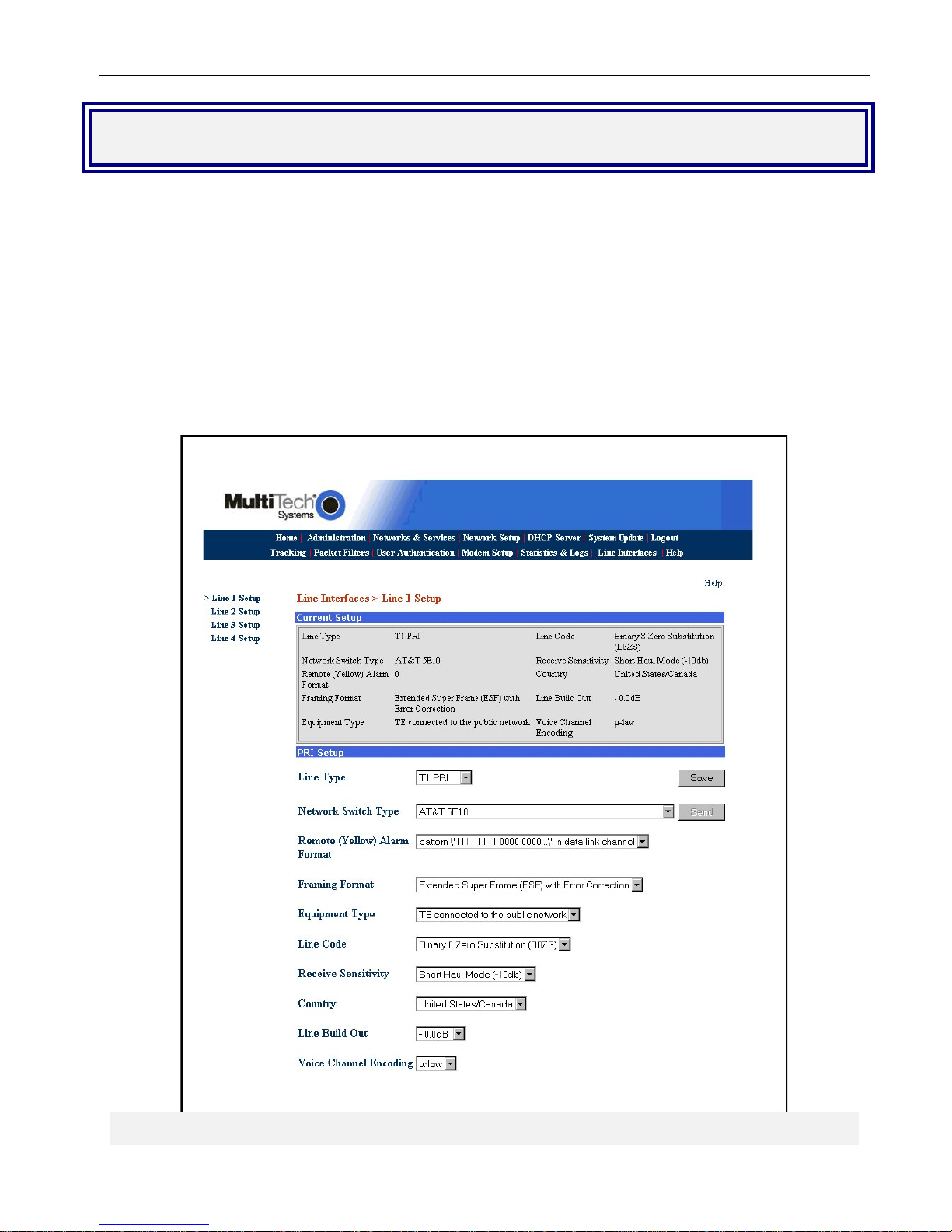
Line Interfaces
To establish your line interfaces for the four LI1 through LI4 interfaces, click on Line Interfaces. The Current
Setup section reflects the current operating parameters for the indicated Line Interface.
1. Click on the Line Type down arrow and select your type of line interface; T1 RBS or T1 PRI for North
America or E1 PRI for the rest of the world, then wait for the screen to refresh.
2. Use the various pull down menus to match the parameters of the Line Interface with the line provisioning
information from your Telco.
Note: A common provisioning issue is the type of framing format which the telco usually refers to as ESF.
But, the MultiAccess gives you a choice of ESF or ESF with error correction. Multi-Tech recommends that
you choose ESF with Error Correction.
3. Click Save and the send button will become active.
4. Click the Send button to cause the new parameters to become active. You must wait 45 seconds for the
screen to refresh and the new configuration to apply, then Current Setup section is updated.
MultiAccess Communications Server MA30120 User Guide 20
Page 21
Chapter 2 – Installation
Modem Setup
The Modem Setup group of menus configure the modems for usage with RAS, modem sharing, and faxing.
The default usage for each modem is RAS. The Modem Setup menu controls the parameters of the modems
set to RAS. If the MultiAccess modems are to be used for dialout, in a networking modem sharing
environment, then use the Modem Usage menu to change the usage to Modem Sharing. If the MultiAccess
modems are to be used for faxing with the integrated Hylafax™ Server, then use the Modem Usage menu to
change the usage to Fax. The Fax Setup menu is used to configure the Hylafax Server for sending and
receiving faxes.
Note: The MultiAccess modems also support faxing with fax servers that are external to the MultiAccess via the
Modem Sharing usage.
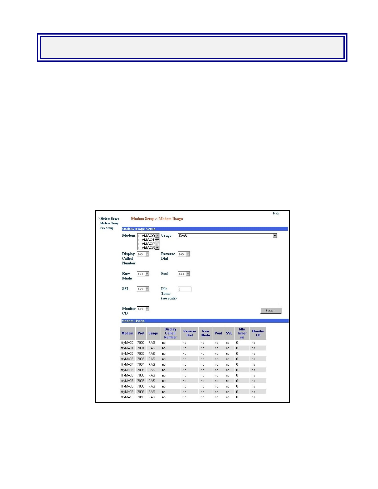
Modem Usage
If you are using all your MultiAccess modems to provide dial-in PPP access, you do not have to modify the
default Modem Usage settings. The default usage is RAS. If you plan to use all or part of your MultiAccess
modems for dial-out, you will have to change the Modem usage settings for the selected modems to one of the
Modem Sharing options that best fit your needs. If you plan to use some or all your modems for faxing, you will
have to change the Modem Usage setting for the selected modems to Fax.
If you are using your MultiAccess in an RAS inbound PPP environment, you do not
have to make any changes in the Modem Usage menu.
Note: When implementing a combination of usage options, care must be given so that inbound calls do not
conflict with outbound calls. This may require changing the hunt group call distribution at the central office and
should be addressed with the provider of your T1/E1 digital line.
Caution: Modem sharing is accomplished by implementing a Telnet interface to the MultiAccess modems.
Make sure that care is taken to secure access to these ports via firewall or IP filter settings to prevent
unauthorized use of your modem resources.
MultiAccess Communications Server MA30120 User Guide 21
Page 22

Chapter 2 – Installation
If you are using your MultiAccess as a network modem pool, you will need to set up
the Modem Usage menu to support your configuration.
1. Click on the Usage drop down arrow and chose the Modem Sharing – authentication type that suits your
applicational needs.
2. Click on the Modem drop up or down arrow and select the tty modem(s) for modem sharing. You can
choose multiple modems by holding down the shift key.
3. When the Modem Usage is set to Modem Sharing, the following options become available:
Display Called Number - This parameter applies to inbound (received) calls when the Line Interface type
is PRI. The telephone number (or final digits) dialed by the originator will be displayed into the telnet socket
following the first “ring” message. The Called Number information (string of digits) is provided by the
central office switch and is commonly referred to as DNIS. The MultiAccess does not support DNIS when
the Line Interface type is T1-RBS.
Reverse Dial - This parameter enables two features, comma dialing and reverse dial mode. When
enabled, the dial string can include the use of commas, used to create a pause between digits of the dial
string (most commonly used to specify the extension of the answering modem).
Example: “atdt18003334444,,,,,4321”. Each comma creates a 2 second pause. 4321 is the extension of
the desitination phone line\modem.
Reverse dial mode is where the dial string includes the letter “r” at the very end of the dial string, the
purpose of which is to instruct the MultiAccess modem to switch from originate to answer mode after
dialing. For example: “atdt17637175549r”.
Please Note: When Reverse Dial is enabled, the dial string must include the tone (t) command, for
example, atdtstring .
MultiAccess Communications Server MA30120 User Guide 22
Page 23

Chapter 2 – Installation
Raw Mode - If Yes, this sets the TCP port to a RAW socket. User data is treated “as is” and the Telnet
Command Escape capability is disabled. If No, this allows the Telnet command parser to look for escape
sequences that are used to communicate control functions. A common example is to support RFC-2217
Com Port Control.
Pool - If you want to access a specific modem, accept the default of No. Each modem will be given a
specific TCP port number, starting at 7000+. If you select pool = Yes, then all selected modems are
accessed via port number 6000 – creating a first available pool, starting with the lowest numbered tty port.
SSL - Support is made available when the usage is Modem Sharing with Authentication. This is only
used with SSL capable Telnet Clients. Site Certificate information needs to be configured appropriately.
Contact Multi-Tech Tech Support for additional information.
Idle Timer (seconds) - The Idle Timer, upon expiring, will hangup the modem and close the telnet socket.
Idle time is defined as no data flow in both directions. Any data sent or received across the socket will
cause the Idle Timer to start over. When there has been no data activity for the duration specified, the idle
timer will expire.
Monitor CD - Upon the modem disconnecting, the MultiAccess will close the telnet socket to the host
application server.
4. Click on the Save button.
MultiAccess Communications Server MA30120 User Guide 23
Page 24
Chapter 2 – Installation
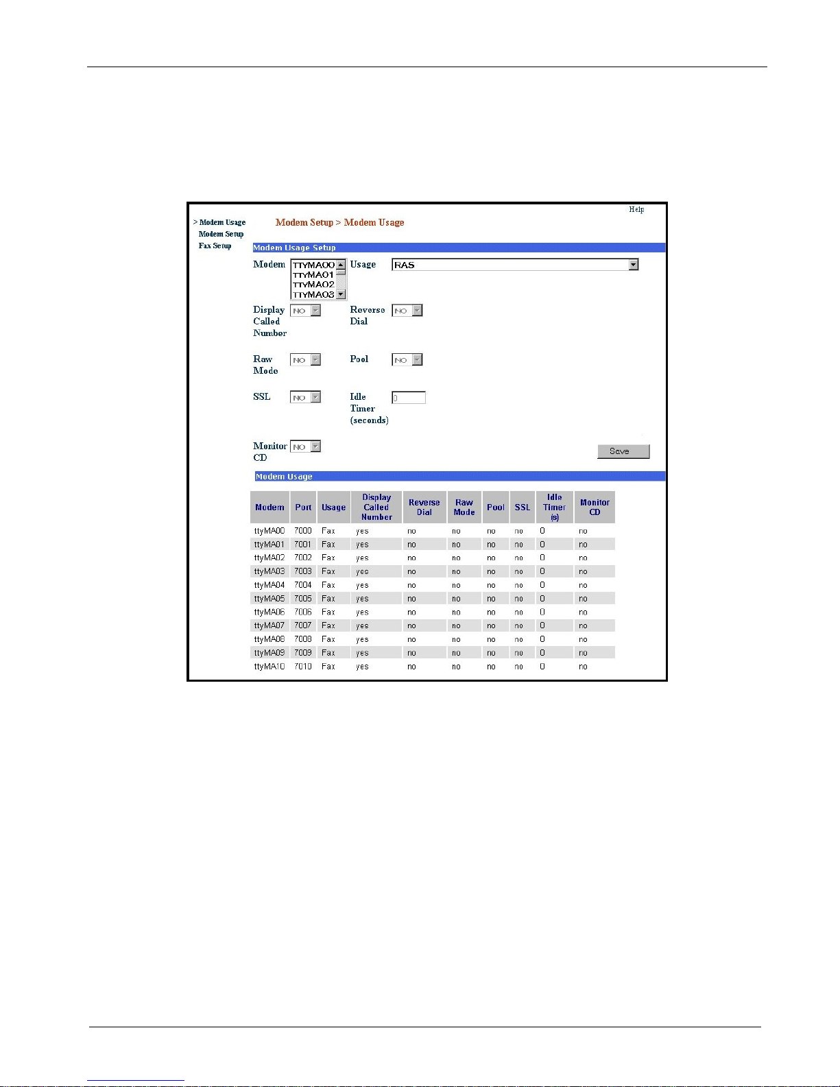
If you are using your MultiAccess as a network fax server, you need to set up the
Modem Usage menu to support your configuration.
5. Click on the Usage drop down arrow and select Fax.
6. Click on the Modem up or down arrow and select the tty modem(s) for faxing. You can choose multiple
modems by holding down the shift key.
7. Click on the Save button.
MultiAccess Communications Server MA30120 User Guide 24
Page 25
Chapter 2 – Installation
Modem Setup
Modem Setup screen only applies when the Modem Usage is set for RAS (Dial-in PPP). RAS usage is defined
in the Modem Usage Setup field of the Modem Usage screen.
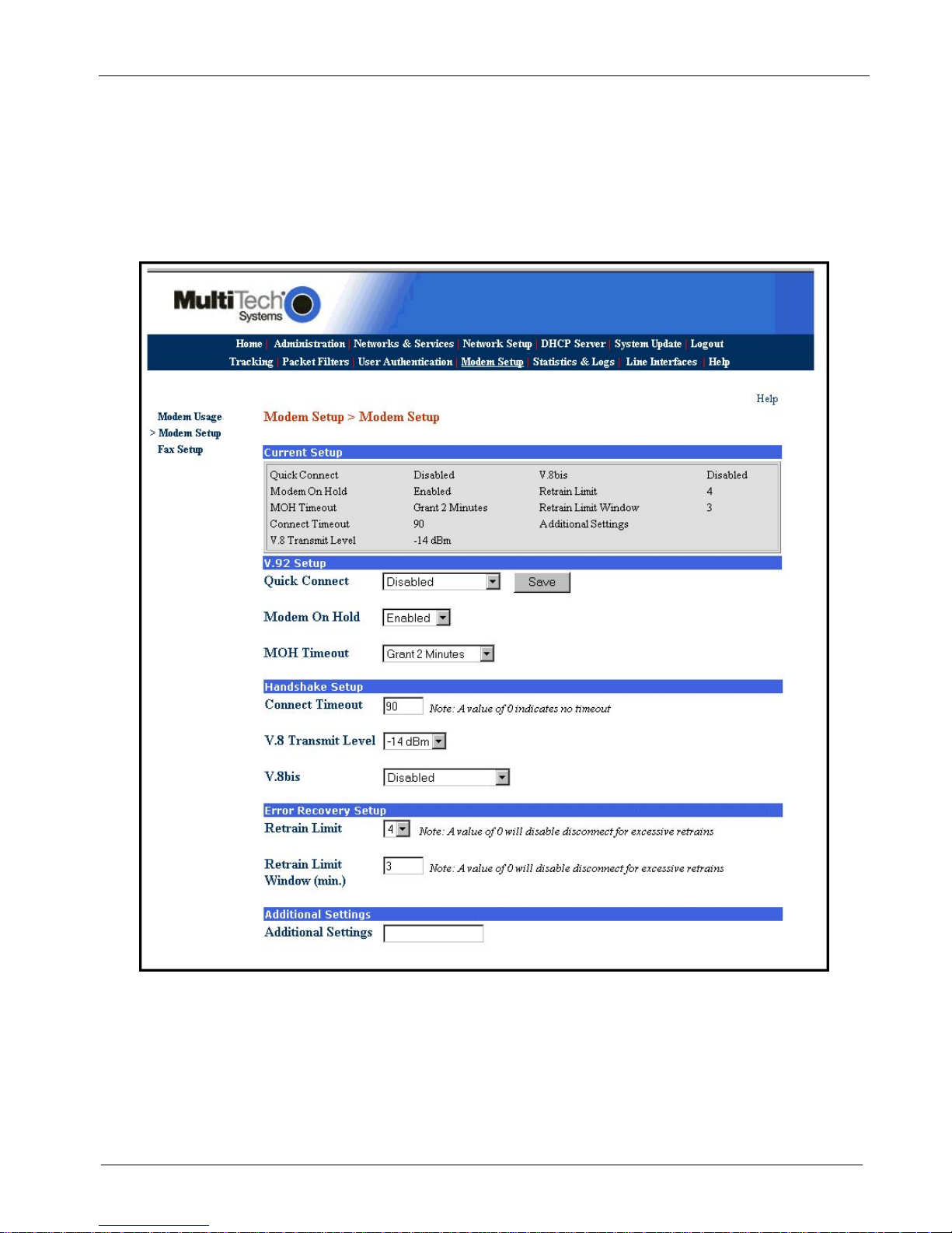
1. Verify that the V.92 Setup parameters conform to your client’s characteristics.
2. Multi-Tech recommends that you set Retrain Limit to 4 and due to compatibility issues seen with
various modems, you may wish to disable Quick Connect and V.8bis.
3. If additonal modem commands are required, refer to Appendix B, Advanced Commands.
MultiAccess Communications Server MA30120 User Guide 25
Page 26
Chapter 2 – Installation
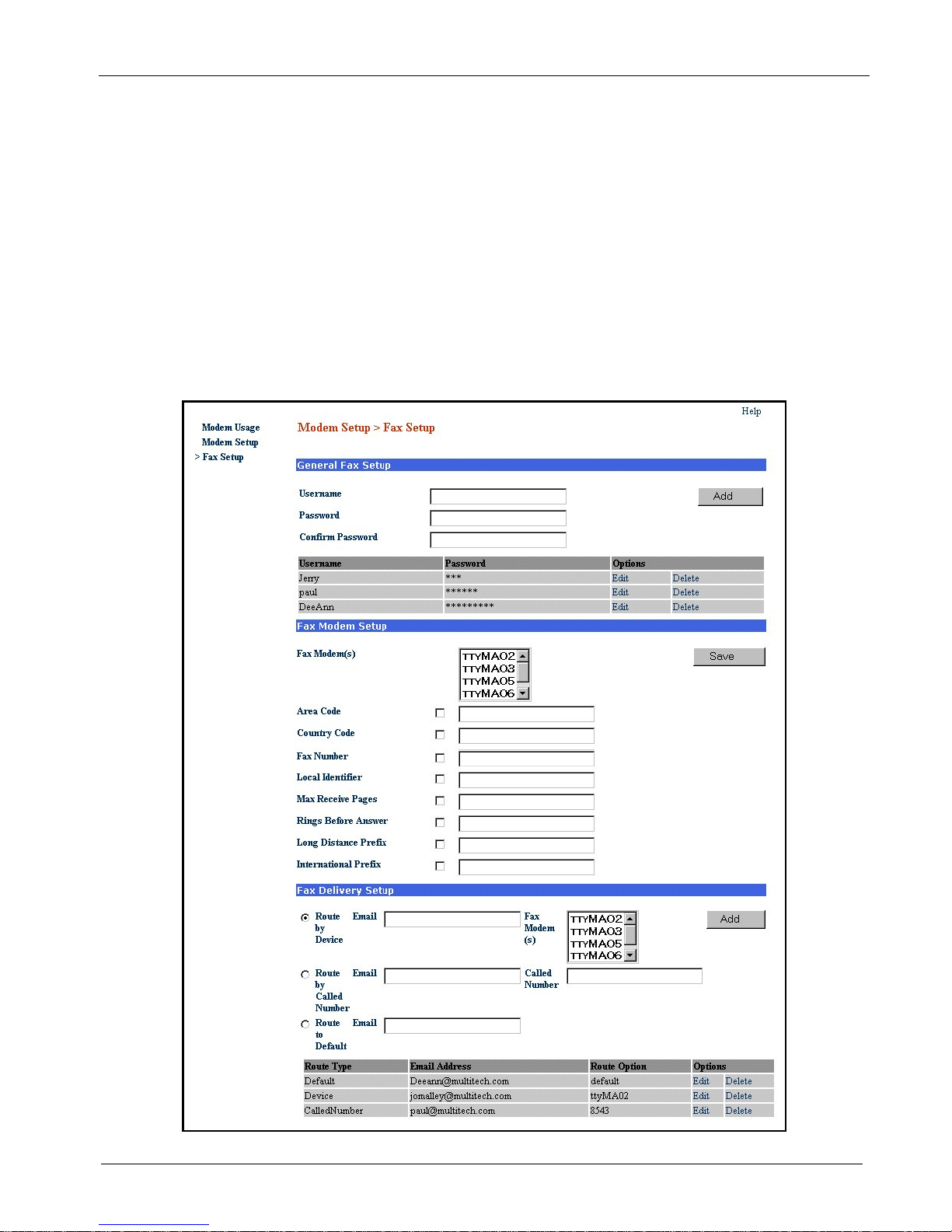
Fax Setup
Fax setup is initiated when you allocate modem(s) to the integrated Hylafax™ Fax Server. This is achieved by
setting the selected modem’s usage to Fax. If no modems are set for fax usage, then only the General Fax
Setup section is displayed. The Fax Setup screen is used to configure the integrated Hlyfax Server for sending
and receiving faxes.
The sending of outbound faxes via the Hylafax Server requires the use of a Hylafax compatible Fax Client
software, e.g., Multi-Tech’s FaxFinder Client. The General Fax Setup group is used to add Fax Clients to the
Hylafax server.
The Fax Client must be installed on each workstation that you wish to send faxes from. The Fax Client must
use the credentials defined in the General Fax Setup group to submit faxes for sending. The Fax Client is not
used for receiving faxes.
Inbound faxes received from the T1/E1 digital line are converted to tiff files and then emailed from the Hylafax
server to the specified recepient. The Fax Delivery Setup group is used to configure the routing of inbound
faxes.
MultiAccess Communications Server MA30120 User Guide 26
Page 27

Chapter 2 – Installation
Outbound Fax Client Data Base
The outbound fax client data base is generated in the General Fax Setup group. The current outbound fax
client data base is shown in the table at the bottom of the General Fax Setup group. The credentials defined
here are to be used by the fax client. The fax client uses these credentials when accessing the Hylafax server.
1. To establish a fax client data base, enter each user name and password in their respective windows and
click the Add button for each entry.
Note: All fax clients can use the same set of credentials, or a unique set for each client can be added.
Fax Modem Settings
These settings are used to define the fax station identity and other administrative variables. The default
settings are normally sufficient with the exception of the “Rings Before Answer” parameter. When the Called
Number feature is used, the Rings Before Answer must be set to 2 for all the ports. Each Fax Modem is to be
configured with a unique Local Identifier, which is used as the TSI (Transmit Station Identifier) when sending
faxes and is included in the body of the email when receiving faxes. You can limit the maximum number of
pages being received.
Inbound Fax Data Base
The Fax Delivery Setup group is used to configure the routing of inbound faxes. The current fax routing table is
shown at the bottom of this group. Who the fax should be delivered to (routed to) is determined by one of two
routing methods:
A) “Route by Device” (what tty port the fax was received on),
B) Route by Called Number” (number dialed by the remote sender).
Route by Device is a static delivery method, where all faxes that are received on that particular port will be
sent to the email address defined for that port.
8. To deliver the fax based on the port (device) it was received on, select the radio button “Route by Device”
and then highlight the ttyMXxx port(s) from the corresponding window in the Fax Delivery Setup group,
1. Enter the email address of the fax recipient in the Email window and then click add.
Route by Called Number is a dynamic delivery method that requires the use of a PRI line (T1-PRI or E1-PRI
line type). Route entries are to match the DNIS information (provided by Telco per call) to an email address.
The Telco switch will (via PRI signaling) provide DNIS digits to the MultiAccess at the time of ringing (call
setup). How many digits will Telco be providing? The remote originator of the fax may dial 11 digits (1-800333-4444) but Telco may only provide the last x number of digits (where x is commonly = 4). DNIS digits
provided by Telco is a variable to be determined at the time of ordering and installing the PRI service. If no
Called Number route entries can be matched to the DNIS provided for that call - the default route entry will be
used.
1. To deliver the fax based on the number dialed, select the radio button “Route by Called Number”.
2. Enter the email address of the fax recipient in the Email window.
3. Enter the DNIS string matching the number dialed and then click add.
9. The entry should be added to the route table found at the bottom of the screen.
MultiAccess Communications Server MA30120 User Guide 27
Page 28
Chapter 2 – Installation
User Authentication
User authentication is established using Radius Client and Radius Server screens. The Radius Client informs
the MultiAccess of where the Radius Server is located. If your network already has a Radius Server, you do not
have to enter the Radius Server screens. The Radius Server screens are only used when the Radius Server in
the MultiAccess is going to be used. Initially the Radius Server > Default User Setup screen displays the default
settings that are used for dial in network access. Initially these default settings are all that you should need to
authenticate a remote user.
Note: When using the internal Radius Server, you must use the IP address of network card 1 (eth0).
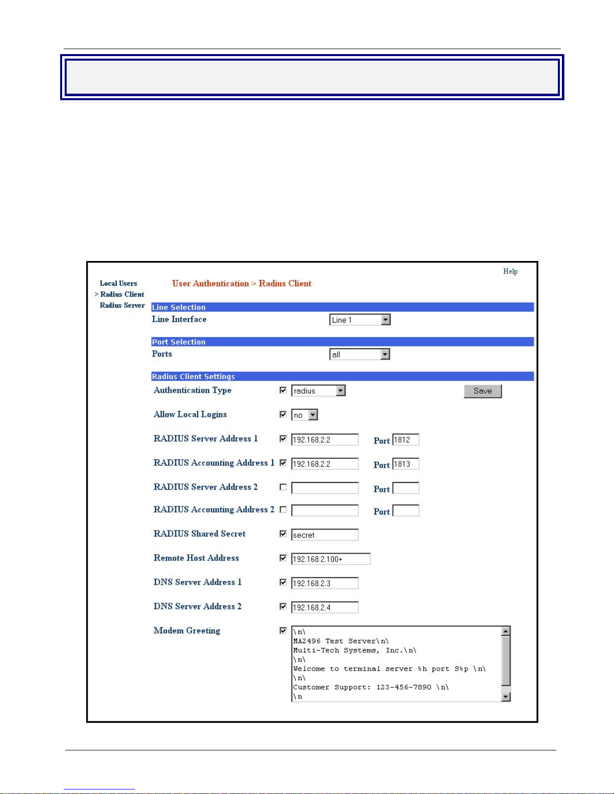
Radius Client
1. Choose User Authentication >Radius Client.
2. Click on Line Interface and select the Line number you selected in the Line Interface screen.
MultiAccess Communications Server MA30120 User Guide 28
Page 29

Chapter 2 – Installation
3. Choose the Authentication Type that is being used in your situation by clicking on the down arrow and
highlighting the Authentication Type. Radius is the default. You can choose from none, radius, tacacs,
remote, local, and radius/local.
4. We recommend that you leave Allow Local Logins set to the default of no.
Caution: If you change this to yes and put a “!” before the login name, you could be setting up a potential
security risk. You can use this in an emergency situation if your radius server goes down.
5. Enter the IP address of your main Radius server in RADIUS Server Address 1 window.
Note: When using the internal Radius Server, both server and client must used the IP address network card
1 (eht0).
6. Enter the UDP port number used by your main Radius server in the first Port window.
7. Enter the IP address of your main Radius Accounting host in the RADIUS Accounting Address 1 window.
8. Enter the UDP port number used by your main Radius Accounting host in the second Port window.
9. If you have a second (backup) Radius server, enter the IP address for the backup Radius server in the
RADIUS Server Address 2 window. Follow that by entering the port number of the backup Radius server
in the third Port window. Then enter the backup Radius Accounting host in the RADIUS Accounting
Address 2 window followed by the port number for the backup host in the fourth Port window.
10. Enter your Shared Secret for the Radius Server in the RADIUS Shared Secret window.
11. In the Remote Host Address window, set the starting IP address of your IP address pool (addresses that
are to be assigned to the dial in users). The IP address needs to have a + (plus symbol) after the number
(e.g., 192.168.1.150+). The plus symbol instructs “Portslave” to create an address pool starting with the
address you have entered. Portslave determines the “ending” address number by adding up all the Line
Interface selections that have their “Port Selection” set to “All”. If the MultiAccess server has multiple line
interface modules and all ports are to use an address pool, set this field to the same address
(192.168.1.150+) for each line interface.
12. Enter the IP address of your primary name server in the DNS Server Address 1. This establishes the
name server for remote access users. If you have a backup DNS server, enter the IP address of your
backup DNS Server in the DNS Server Address 2 window.
13. Click the Save button when you are finished.
14. Repeat the above procedure for each line interface.
MultiAccess Communications Server MA30120 User Guide 29
Page 30
Chapter 2 – Installation
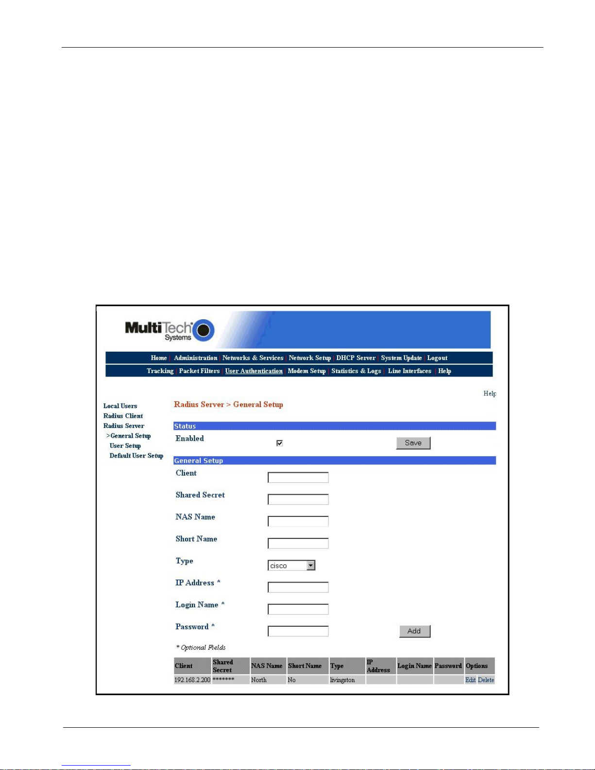
Radius Server > General Setup
If you are going to use the Radius Server that comes with your MultiAccess, then you need to tell the Radius
Server who the Radius Clients are. You need one entry for each Network Access Server (NAS) in your
network.
Note: When using the internal Radius Server, you must use the IP address of network card 1 (eth0).
1. You can enable status by clicking on the Enabled window.
2. Enter the IP address of network card 1 (eth0) in the Client window. This IP address tells the Radius Server
where the Radius Client is located.
3. Enter the same Shared Radius Secret used in the Radius Client screen in the Shared Secret window. The
Shared Secret in the Radius Server and the Radius Server Secret in the Radius Client have to be the same
in order for the two to communicate.
4. You can enter an arbitrary name, unique name for each NAS in the Short Name window.
5. Select the manufacture of radius client/NAS that is being used in your system from the Type drop down
arrow. For example, multitech, livingston, or etc.
6. The three optional items are to restrict logins.
7. Click Add when you are finished.
MultiAccess Communications Server MA30120 User Guide 30
Page 31

Chapter 2 – Installation
Radius Server > User Setup
The User Setup screen establishes who the remote access user is. A user name and password has to be
entered for each remote user that is dialing in to the MultiAccess. The User name and password of the remote
user is all that is needed initially. If you check or enable Service Type through IP Address windows you will over
ride the Default User Setup.
1. Enter the remote user’s name in the Username window.
2. Enter the password of the remote user in the Password window.
3. The Authentication Type should remain at the default setting.
4. Click the Add button when you are finished.
MultiAccess Communications Server MA30120 User Guide 31
Page 32

Chapter 3 – Software
r
g
Chapter 3 - Software
This chapter describes each screen and its function in the MultiAccess Communications Server software.
The aim of the administrator in setting the options in the software should be to let as little as possible and as
much as necessary through the MultiAccess, for both incoming as well as outgoing connections.
The Menu bar provides the organization of this chapter.
Home: The main screen.
Administration: System setup such as Time & Date, Web management, and certificate. Provides for
system shutdown and restart, plus other administrative tools such as PING, Trace Route, and TCP Connect.
Networks & Services: Define networks, services, and groups to make them available to be used by other
functions such as allowed networks, and packet filters.
Network Setup: Set up the LAN 1, and LAN 2 Ethernet ports, etc.
DHCP Server: Configure the DHCP server settings.
System Update: Update services can be downloaded from the update server to keep your system
continually updated.
Logout: Logout and return to the login screen
Tracking: Set up tracking of all packets through the network ports in the MultiAccess.
Packet Filters: Define filter rules and ICMP rules.
User Authentication: Defines security protocol methods, passwords, and user database details.
Modem Setup: Defines the primary role of the modem; RAS, fax, or network modem pool.
Statistics & Logs: View and download all the statistics and log files maintained by your system.
Line Interfaces: Defines setup information of your PSTN lines.
Help: (Online Help) Describes what to do on each screen.
Options Under Each Menu
Home Administration Networks &
Services
Return to
the Main
Menu
System Setup
SSH
SNTP Client
Web Admin
Site Certificate
Database Setup
Backup Setup
Available Backups
Intrusion Detection
Network Tools
System Tools
Tracking Packet Filters User
Accounting Packet Filter Rules
Add User Defined
Filters
ICMP
Networks
Services
Network Groups
Service Groups
Authentication
Local Users
Radius Client
Radius Server
Network
Setup
Interface
Routes
Masquerading
SNAT
DNAT
Modem
Setup
Modem Setup
Modem Usage
Fax Setup
DHCP Serve
Subnet Settings
Fixed Addresses
Statistics &
Logs
Setup
Uptime
Networks
Interface Details,
Routing Table,
Network Connections
Line Interface Status
Modem Connections
Connections,
Connection Details,
Caller ID, Call History
Server Connections
Interfaces
Accounting
Self Monitor
View Lo
s
System
Update
Available
Applied
Setup
Line
Interfaces
Line 1 Setup
Line 2 Setup
Line 3 Setup
Line 4 Setup
Logout
Exit the Program
Help
Administration
Networks &
Services
Network Setup
DHCP Server
System Setup
Tracking
Packet Filters
User Authentication
Modem Setup
Statistics & Logs
Line Interfaces
MultiAccess Communications Server MA30120 User Guide 32
Page 33

Chapter 3 – Software
Home and Logout
Home and Logout Options
Home
This is the opening screen of the MultiAccess Communication Server Web Management software.
MultiAccess Communications Server MA30120 User Guide 33
Page 34

Chapter 3 – Software
Home and Logout
Logout - How to Exit MultiAccess Communications Server Software
The best way to exit the MultiAccess Communications Server system is to choose Logout from the Menu
bar.
If you close the browser in the middle of a session without logging out, the session stays active until the
end of the time-out. If you reopen the session during the time-out, a prompt comes out saying “Some body
is already logged in – Do you want to log the user out?” you respond with Yes and a new session is started.
The timeout period is set at Administration > Web Admin > Time before automatic disconnect. If you
change the Time before automatic disconnect, you have to click the Save button for the new disconnect
time to be active.
When you are done in Administration > Web Admin, click Logout on the menu bar. The browser
connection is terminated and you are returned to the Login screen. Note that hitting the browser’s Back
button will not effectively return you to the previous menu or directory.
MultiAccess Communications Server MA30120 User Guide 34
Page 35

Chapter 3 – Software
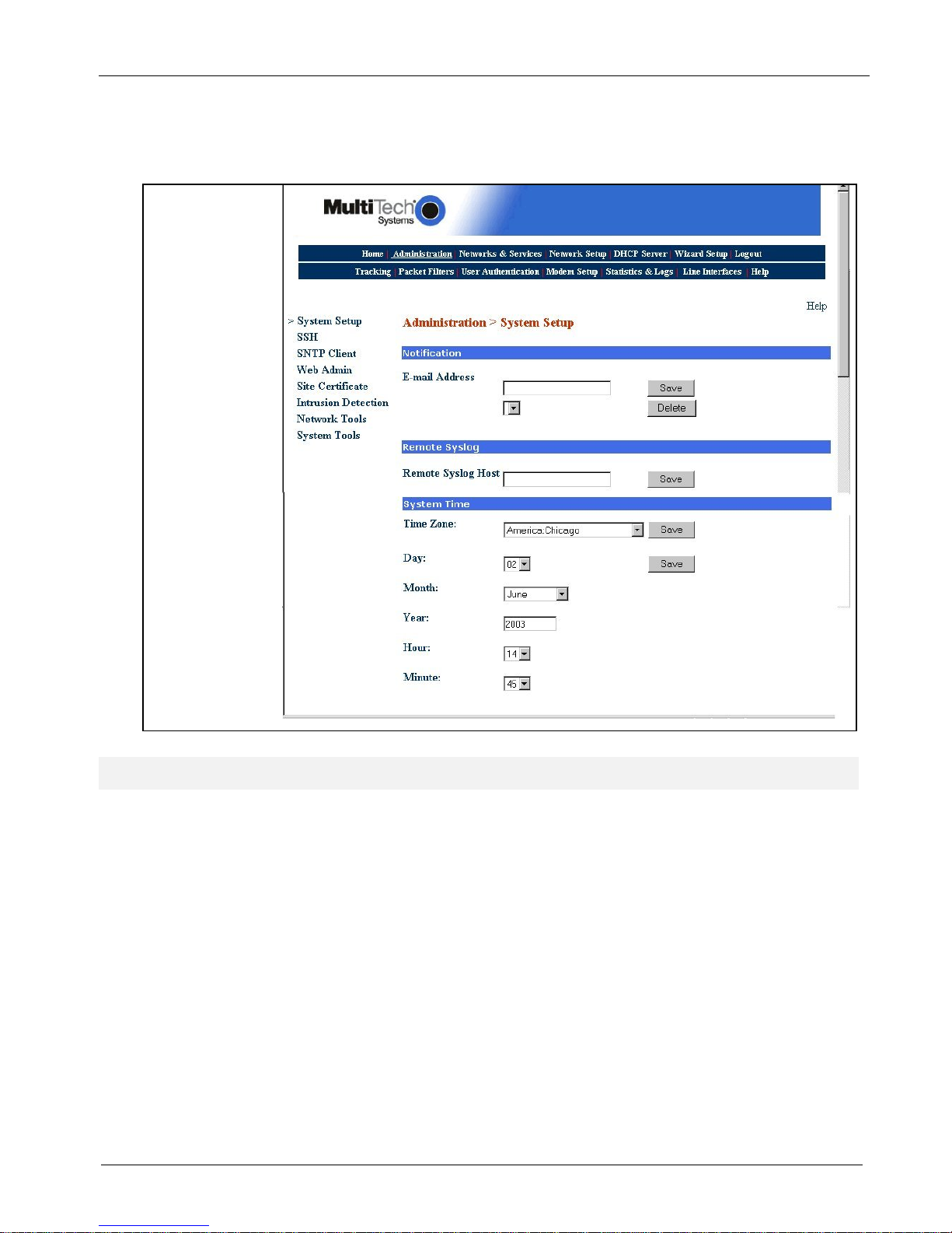
Administration > System Setup
Administration
Administration > System Setup
In the Administration section, you can perform the general system-based settings for the MultiAccess
Communications Server functions.
System Setup includes general system parameters such as the email address of the administrator, remote
syslog host, and the system time can be set through these settings.
MultiAccess Communications Server MA30120 User Guide 35
Page 36

Chapter 3 – Software
Administration > System Setup
Notification - Email Address
This field defines the email address of the administrator to whom emails must be sent in case of any
particular event. The email address has to be entered in proper user@domain
to the administrator on hard disk usage exceeding 70%, Intrusion Detections, backups, license key expire,
self monitor problems, invalid web logins, and invalid SSH logins. The mail settings have to be saved in the
server’s configuration. So the session will be terminated and the web server will be restarted.
Type the Email Address of the administrator who will receive email notifications of any one of the system
events listed below. Click Save. You then have the option to delete the entry.
Types of Notifications the MultiAccess Will Send:
System license key - on expire, from 10 days before expire.
SSH invalid login - Not
Web invalid login - Works
Intrusion Detection - File System Integrity
Intrusion Detection - SNORT (Network Intrusion Detection)
Backup - backup file on export will be sent.
Update services - system update completion.
Disk usage exceeding 70%, disk usage exceeding 80% (after cleanup)
Self monitor
format. Emails will be sent
Remote Syslog - Remote Syslog Host
In the Remote Syslog field, type the IP Address of the desired remote Syslog Host and click Save.
This setting enables the sending of all logged messages to a host that is your syslog host.
System Time
This selection sets the system time. The year, month, hour, and minute have to be selected from the
options provided. After the selection is made, click Save to get the system time changed. The selected date
should match the corresponding month and year, i.e., if the date selected is 29, month is February and the
year is 2001, the time will not be saved because for the year 2001, February has 28 days.
MultiAccess Communications Server MA30120 User Guide 36
Page 37

Chapter 3 – Software
Administration > SSH
Administration > SSH
SSH (Secure Shell) is a program to log into another computer over a network to execute commands in a
remote machine and to move files from one machine to another. It provides strong authentication and secure
communications over insecure channels. It is intended as a replacement for rlogin, rsh, and rcp.
SSH is a command line interface. Access via SSH is encrypted.
For access via SSH, you need SSH Client, which most Linux systems already include. For MS Windows, the
program PuTTY is very common as a SSH client.
Status
This screen opens with Status as the only prompt. Once it is checked and saved, SSH is enabled and the
other options display.
SSH requires name resolution for the access protocol, otherwise a time-out occurs with the SSH
registration. This time-out takes about one minute. During this time it seems as if the connection is frozen,
or can’t be established. After that the connection returns to normal without any further delay.
Allowed Networks
The networks that are to be allowed to access the MultiAccess using SSH must be enabled.
The default setting Any in Allowed Networks means everyone is allowed to access the SSH service.
Networks are be defined in Networks & Services > Networks menu.
Caution: The default setting (Any) allows everyone to access the SSH service. For security reasons we
recommend that you restrict the access to the SSH service. You should delete access from all other
networks!
MultiAccess Communications Server MA30120 User Guide 37
Page 38

Chapter 3 – Software
Administration > SNTP Client
Administration > SNTP Client
SNTP (Simple Network Time Protocol) is an Internet protocol used to synchronize the clocks of computers to
the same time source. Clicking the SNTP Client check box enables the MultiAccess to act as a SNTP client.
SNTP Client
Check the SNTP Client box to activate SNTP Client.
SNTP Server Address
Enter the IP address of the SNTP Server for which the firewall will contact to synchronize its clock. Then click
the Save button.
MultiAccess Communications Server MA30120 User Guide 38
Page 39

Chapter 3 – Software
Administration > Web Admin
Administration > Web Admin
From this screen you can regulate Web Admin access. The Web Admin interface uses the Secure HTTP
protocol (S-HTTP, aka HTTPS) for secure transactions. Secure HTTP provides communication between your
browser and the MultiAccess.
S-HTTP supports end-to-end secure transactions, in contrast with the original HTTP authorization mechanisms,
which require the client to attempt access and be denied before the security mechanism is employed. With SHTTP, no sensitive data need ever be sent over the network in the clear. S-HTTP provides full flexibility of
cryptographic algorithms, modes, and parameters.
Web Admin
Available Networks
Select the networks that will allow access to Web Admin. The list includes those networks you entered
under Networks & Services > Networks. You can add and delete existing selections. The MultiAccess will
display an ERROR message if you try to delete access to a network that would cause you to lock yourself
out or otherwise not make sense.
Allowed Networks
As with SSH, Any has been entered here for ease of installation. ANY allows Web Admin to be accessed
from everywhere once a valid password is provided.
Caution: As soon as you can limit the location from which the MultiAccess is to be administered (e.g., your
IP address in the internal network), replace the entry ANY in the Allowed Networks with a smaller network.
If you want only one administrative PC to have access to the MultiAccess, you can do this by defining a
network with a address of a single computer from the Networks and Services > Networks screen.
MultiAccess Communications Server MA30120 User Guide 39
Page 40

Chapter 3 – Software
Administration > Web Admin
Change Password
You should change the password immediately after initial installation and configuration, and also change it
regularly thereafter. Only alphanumeric characters are allowed. To change the password, enter the existing
password in the Old Password field, enter the new password into the New Password field, and confirm your
new password by re-entering it into the Confirmation entry field.
Caution: Use secure passwords! For example, your name spelled backwards is not secure enough;
something like xfT354 is better.
Time Before Automatic Disconnect
An automatic inactivity disconnection interval is implemented for security purposes. In the Time Before
Automatic Disconnect entry field, enter the desired time span (in seconds) after which you will be
automatically disconnected from Web Admin if no operations take place.
After the initial installation, the default setting is 3000 seconds. The smallest possible setting is 300
seconds. If you close the browser in the middle of an open Web Admin session without leaving Web Admin
via Logout, the last session stays active until the end of the time-out.
If you do not logout, the next attempt to login, during the unexpired duration, will give you a pop-up stating
“someone else is logged in – Do you want to kick them out?
WebAdmin HTTPS Port
HTTPS Port
This field is for setting the HTTPS port for Web administration. After setting the HTTPS port, the
connection is terminated. The browser settings have to be changed for the new port number before
starting the next session. By default, port 443 is configured for HTTPS sessions. The value of the port
number should lie between 1 and 65535. Well known ports and ports already used by the MultiAccess are
not allowed.
MultiAccess Communications Server MA30120 User Guide 40
Page 41

Chapter 3 – Software
Administration > Site Certificate
Administration > Site Certificate
Public keys are used as the encryption algorithm for security systems. For the validity of public keys,
certificates are issued by a Certificate Authority. The Certificate Authority certifies that the person or the entity is
authenticated and that the present public key belongs to that same person or entity. As the certificate contains
values such as the name of the owner, the validity period, the issuing authority, and a stamp with a signature of
the authority, it is seen as a digital pass. On this screen, you enter server certificate information, which the
MultiAccess needs to authenticate itself to your browser. After saving the settings, the browser’s security
information settings have to be cleared.
Certificate Information
Country Code - Use the default (United States) or change to the country of operation.
State or Region - Type the state, province, region of operation.
City - Type the city name.
Company Organization Unit Contact Email - Type the email address of the contact for MultiAccess certificate data (e.g., the
MultiAccess administrator) over the default (myname@mydomain.com).
Firewall Hos
access the Web Admin interface. It can be one of the MultiAccess IP addresses.
Example: If you access Web Admin with https://192.168.10.1
192.168.10.1. If you access Web Admin with a DNS host name (e.g., https://MultiAccess Communications
Server.mydomain.com), then use this name instead.
When you have entered the values, click Save. The browser will reconnect to the MultiAccess. At the
security Alert screen, click View Certificate. Then click Install Certificate if you have not previously
installed it:
Type the company name.
Type the organizational unit (e.g., Sales & Marketing).
t Address -
1. When the first screen displays, click the Install Certificate button.
2. On the Welcome to Certificate Import Wizard screen, click the Next button.
3. On the Certificate Manager Import Wizard screen, click Next. You can elect to have the
certificate automatically placed into a directory or you can Browse and choose your own
directory. If you elect to place all certificates into a selected location, follow the on-screen
prompts for Select Certificate Store, Physical Stores, and Root Stores.
4. When the certificate has been added to the Root Store, the Completing the Certificate Manager
Import Wizard displays. Click Finish.
Enter the MultiAccess‘s host address. Use the same address that you will use to
, the MultiAccess Host Address must also be
MultiAccess Communications Server MA30120 User Guide 41
Page 42

Chapter 3 – Software
Administration > Database Setup
Administration > Database Setup
Database Setup defines where the call history database is located and maintained. If the database is to be
located on this machine and other MultiAccess units are joining the data base as clients, you will need to
provide client access by entering the Client IP Address, Mask, and the access method. If the database is
located on a remote machine, you will need to provide the IP address of the remote machine, and appropriate
user name and password.
Database Location
Selects where the database is located, Local or Remote. If the database is located on this machine, select
Local. If the database is located on a remote machine, select Remote and provide the IP Address of the
remote machine, and the Username and Password.
Local Database Server Setup
The Local Database Server Setup allows you to setup client access for the remote servers that will be
sending call history records to this data base. The IP address along with the mask allows you to determine
which clients are provided access to the database. The Client Method can be password, trust, reject, or
md5.
MultiAccess Communications Server MA30120 User Guide 42
Page 43

Chapter 3 – Software
Administration > Backup Setup
Administration > Backup Setup
The Backup Setup allows you to enable and control specific aspects of the periodic back-up process. This
process allows you to save your settings as .tar file either on your local system or up loaded to an FTP server.
The Backup process consists of copying hundreds of configuration files into one .tar file. The .tar is then zipped
and named per “config-year month day hour minute.tar.gz”.
When a periodic backup is enabled, the backup occurs approximately 16 minutes after midnight, per the
selected interval.
The Backup file is useful in crash recovery/system restoral situation and handy for setting up fail-safe spares.
The specific configuration files that get backed up are listed in the file called “backup” located in the /opt/multiaccess/data/directory. Backups will fail if this file is renamed or missing from this directory.
Local Periodic Backup
If Local Periodic Backup is chosen, the Time Interval can be selected as a daily, weekly, or monthly
backup. The number set in the Maximum Backups is the number of backups that are saved on your
system.
FTP Periodic Backup
If FTP Periodic Backup is chosen, the backup is uploaded to the FTP server designated in the Server IP
Address field and a specific Directory can be designated in the Directory field. The Time Interval can be
selected as daily, weekly, or monthly. A weekly FTP backup is the default. The backup can be security
protected by using a Username and Password protection. The username and password are FTP Client
credentials used to log into the FTP server. The credentials must have write access on the FTP server.
MultiAccess Communications Server MA30120 User Guide 43
Page 44

Chapter 3 – Software
Administration > Available Backups
Administration > Available Backups
Available Backups allow you restore a previous saved configuration. The number set in the Maximum Backups
field in the Backup Setup determines the number of backups listed here.
Backups
You can Get, Restore, and Delete backups. To Restore a backup, simply click on the Options Restore.
Your system will be restored from the file and rebooted. To Delete a backup, click on the Options Delete
and the file is removed from your system.
For situations when you want to use the backup that is on the FTP server, manually copy/get the file and
place it into the /var/log/backup directory. Then it will be listed as a available configuration backup.
MultiAccess Communications Server MA30120 User Guide 44
Page 45

Chapter 3 – Software
Administration > Intruder Detection
Administration > Intrusion Detection
The Intrusion Detection mechanism is used to notify the administrator if there has been any tampering with the
files on the server.
Intrusion Detection
Enable File Integrity Check
Check the box to enable File Integrity Checking. Select the amou
conduct this check. Options are every 5 Minutes, Hourly, or Daily. Then click the Save button.
nt of time you would like the system to
Network Intrusion Detection
Enable Network Intrusion Detection
This allows the user to detect attacks on the network. In the event that a port scan is carried out by hackers
who are looking for the weak spots in a secure network. This feature informs the administrator by email as
soon as the attack has been logged. The administrator can decide what actions are to be taken. By default,
DOS attack, minimum fragmentation checks, port scans, DNS attacks, bad packets, overflows, chat
accesses, Web attacks will be detected; and then the administrator is informed. Apart from the above, the
user can configure user defined rules for intrusion detection.
Check the box to enable Network Intrusion Detection. Then click the Save button.
User Defined Network Intrusion Detection Rules
SRC IP Address
This selection allows you to choose the network from which the information packet must be sent for the rule
to match. Network groups can also be selected. The ANY option matches all IP addresses, regardless of
the whether they are officially assigned addresses or private addresses. These Networks or groups must
be predefined in the Networks menu.
Destination IP Address
This selection allows you to choose the network to which the information packet must be sent for the rule to
match. Network groups can also be selected. These network clients or groups must have been previously
defined in the Networks menu.
MultiAccess Communications Server MA30120 User Guide 45
Page 46

Chapter 3 – Software
Administration > Intruder Detection
Protocol
This selection allows you to choose the type of protocol, i.e., TPC or UDP.
Service
This selection allows you to choose the corresponding service. The service must have been previously
defined in the Services menu. Select intrusion detection rules from the following dropdown list boxes:
Add
After the rules are defined/selected, click the Add button. The commands can be deleted by clicking Delete
under the Command option.
MultiAccess Communications Server MA30120 User Guide 46
Page 47

Chapter 3 – Software
Administration > Network Tools
Administration > Network Tools
There are three tools that can help you test the network connections and functionality. Ping and Trace Route
test the network connections on the IP level. TCP Connect tests TCP services for availability.
PING
Ping is an acronym for Packet Internet Groper. The PING utility is used as a diagnostic tool to determine if
a TCP/IP communication path exists to a remote host. The utility sends a packet to the specified address
and then waits for a reply.
Host - Specify the IP address or name of the other computer for which connectivity is to be checked.
Number of PINGS - Select the number of pings. You can choose 3 (the default), 10 or 100 pings.
Timeout - Specify the duration to wait before declaring “timeout, “no response”.
Packet Size (bytes) - Specify the number of data bytes to be sent.
Start - After clicking the Start button, a new browser window opens with the PING statistics
accumulating.
MultiAccess Communications Server MA30120 User Guide 47
Page 48

Chapter 3 – Software
Administration > Network Tools
Trace Route
Trace Route is a tool for finding errors in the network routing. It lists each router/hop/network on the way to
remote host. If the path for the data packets is temporarily unavailable, the interruption is indicated by
asterisks (*). After a number of tries, the attempt is aborted. The interrupted connection can have many
causes, including the packet filter on the MultiAccess not allowing the operation of Trace Route.
Host
Specify the IP address (host name) of the other computer to test this tool.
Start
Click the corresponding Start button to start the test.
A Sample Trace Route Log
TCP Connect
This system tool tests specific TCP ports for availability between the source MultiAccess and destination
addresses.
Host – Enter the IP address or host name of the destination.
Port – Enter the port number in the Port window. For example, port number 23 for telnet service.
Start – Start the test connection by clicking the Start button.
The results are:
Connected to host
Connection refused by host
Not route to host
MultiAccess Communications Server MA30120 User Guide 48
Page 49

Chapter 3 – Software
Administration > System Tools
Administration > System Tools
System tool includes Restart, and Shutdown. Restart allows the MultiAccess to be shut down and restarted.
Shut down ensures that all services are shut down correctly.
Restart
By clicking the Restart button, the MultiAccess is shut down and rebooted. The message Are you sure you
want to restart the system? is displayed. By clicking the OK button you confirm that you want to restart the
MultiAccess. The login screen displays while the restart process takes place. The unit is first brought to run
level 0, which takes approximately 30 seconds to reach. At this point the system BIOS is restarted and the unit
begins to boot up. You will be able to log back in when run level 3 has been reach, which usually takes about 2
minutes. However the boot up process is subject to a number of variables that could dramtically increase the
time needed to reach run level 3.
Shutdown
This tool should be used when AC power is to be removed from the unit (moving the unit or adding MA30EXP
expansion modules). Clicking the Shutdown button starts the shutdown process. The message Are you sure
you want to shut down the system? is displayed. By clicking the OK button you confirm that you want to
shutdown the MultiAccess. The login screen displays while the shutdown process takes place. When a proper
shutdown is initiated, immediately 1 beep is heard and then the unit starts to shutdown (killing services,
unloading driver, etc) and then approximately 30 seconds later “run level zero” is reached and two consecutive
beeps are heard, after which it is now safe to power off the unit.
Caution: Avoid improper shutdowns. You should switch off the MultiAccess’s power only after you have
completed the shut down process. Improper shutdowns will increase the start up time on the subsequent boot
up. They can in some cases cause or lead to hard drive failures.
Note: Upon initial power up, within 5 seconds one beep is heard at a successful POST of the BIOS,
approximately 90 to 120 seconds later five consecutive beeps will be heard when the system has reached run
level 3. During the boot up time all 12 line interface LEDs will simultaneously flash on/off (repeatedly), until run
level 3 is reached. Line interface and modem drivers take up to an additional 60 seconds to load after run level
3 has been reached. When the line interface and modem drivers finish loading, only the activated line
interfaces will have appropriate LEDs illuminated.
The time needed to fully boot up is a variable depending on the number of modem modules installed, hard drive
variables (journal events and file system checks) and other Linux system variables.
In some rare occasions, timing variables to the shutdown process may result in not all PIDs being removed.
MultiAccess Communications Server MA30120 User Guide 49
Page 50

Chapter 3 – Software
Networks & Services > Networks
Networks & Services
Networks & Services > Networks
A network consists of a unique name, an identifying network number, and a Subnet Mask. Once you add a
network, the information displays at the bottom of the screen. This network table contains the default networks
which cannot be deleted or edited.
Important Notes:
IP address (network number) will change if changes are made to the IP addresses in Network Setup of
Ethernet 1 and Ethernet 2.
To define a single host, enter its IP address and use a netmask of 255.255.255.255. Technically, single
hosts are treated in the same way as networks.
A network or host you added can be deleted only if it is not used for any route or by any other module.
If a network process/function is using a network, that network cannot be edited. Similarly, if a host
address is edited and changed, and if that host was used by SNAT or DNAT, the change will not be
performed.
Add Network
Name
Enter a straightforward name into the Name entry field. Networks can be used to set packet filter rules, static
routes, etc.. Accepted characters: alphabetic, numerical 0 to 9, the minus sign, and underscore. Forward
slash and backward slash are not accepted as a valid character. Maximum characters are 39.
IP Address
Enter the network number (e.g., 192.168.3.0).
Subnet Mask
Enter the Net Mask. Subnet mask 255.255.255.0. Defines a private Class-C net.
MultiAccess Communications Server MA30120 User Guide 50
Page 51

Chapter 3 – Software
Networks & Services > Networks
Confirm your entries by clicking the Add button. After a successful definition, the new network is entered
into the network table. This network will now be referenced in other menus under this name. You can edit
and delete networks by clicking Edit or Delete in the Options column for the network you want to change.
The name of the network can not be changed, but the IP Address and Subnet Mask can be edited. You
can delete a newly created network by clicking on Delete in the Options column for a desired network.
Added networks are displayed in the following functions:
1. Web Admin
2. SSH
3. Packet Filter Rules
4. Network Intrusion Detection
5. Routing
6. Masquerading
7. SNAT
8. DNAT
These names will be made available to:
1. Add allowed networks for Web Admin
2. Add packet filter rules
3. Add source, destination networks for Network Intrusion Detection
4. Add routes in routing, SNAT, masquerading, portscan detection and DNAT sections.
MultiAccess Communications Server MA30120 User Guide 51
Page 52

Chapter 3 – Software
Networks & Services > Services
Networks & Services > Services
On this screen you can set the MultiAccess protocol services. Protocols make ongoing administration easier.
You will define data traffic as it travels the networks (e.g., the Internet). A service protocol setting consists of a
Name, the Protocol, the S-Port/Client (source port), and the D-Port/Server (destination port).
When entering the ports, you can enter a single port or a port range separated by a colon (:).
For AH and ESP, the SPI is a whole number between 256 and 65536, which has been mutually agreed upon
by the communication partners. The Internet Assigned Numbers Authority (IANA) reserves values below 256.
Notes:
TCP & UDP allow both protocols to be active at the same time. Any causes the MultiAccess to accept
any protocol offered.
The ICMP protocol is necessary to test network connections and MultiAccess functionality, as well as for
diagnostic purposes. In the Packet Filter > ICMP menu you can enable ICMP Forwarding between
networks, as well as MultiAccess ICMP reception (e.g., to allow ping support).
The ESP protocol is required for Virtual Private Network (VPN).
The AH protocol is required for Virtual Private Network (VPN).
There are options for editing or deleting the user added services. However, there are some standard services,
which cannot be edited or deleted. If the Packet Filter rules, SNAT, or DNAT uses the service, it cannot be
deleted. For editing any user-defined service, the Edit button has to be clicked to get the fields corresponding
to the service entry. The entries can be saved using the Save button.
MultiAccess Communications Server MA30120 User Guide 52
Page 53

Chapter 3 – Software
Networks & Services > Services
Add Services
Name
Enter a unique name in Name entry field. You will need this later (e.g., to set packet filter rules).
Protocol
Select from the following protocols: TCP, UDP, TCP & UDP, ANY, ICMP, AH, and ESP.
ICMP Type
Select the ICMP type (e.g., echo reply, echo request, time to live exceeded, etc.). It will display if the
protocol type is ICMP>
ICMP Code
Select the ICMP code (e.g., all). It will display if the protocol type is ICMP and the ICMP Type is
redirect network, network unreachable, to time to live exceeded.
S-Port/Client (Source Port)
Enter the source port for the service. The entry options are a single port (e.g. 80), a list of port numbers
separated by commas (e.g. 25, 80, 110), or a port range (e.g. 1024:64000) separated by a colon (:). It will
be displayed if the type of the protocol is TCP, UDP, TCP+UDP, or ANY.
D-Port/Server (Destination Port)
Enter the destination port for the service. It will be displayed if the type of the protocol is TCP, UDP,
TCP+UDP, or ANY.
Add Button
After you have entered the service, click the Add button.
Edit
By clicking Edit in the Options column, the information is loaded into the entry menu of the Edit Service
screen. You can then edit the entry. You can edit user-added services; however, there are some standard
services that cannot be edited.
Delete
By clicking Delete in the Options column, the service is deleted from the Services table. You can delete
user-added services; however, there are some standard services that cannot be deleted. If Packet Filter
rules, SNAT, or DNAT uses a service, it cannot be deleted.
Important:
The user added services are displayed in the following functions:
1. Packet Filter Rules
2. Network Intrusion Detection
3. SNAT
4. DNAT
The user added services are available to:
1. Add packet filter rules
2. Add specific services for Network Intrusion Detection.
3. Add rules in SNAT and DNAT functions.
MultiAccess Communications Server MA30120 User Guide 53
Page 54

Chapter 3 – Software
Networks & Services > Network Groups
Networks & Services > Network Groups
On this screen you can group various networks into a group. The networks that were added in the Network &
Services > Networks section can be placed into a group.
A network, which is already a part of a group, cannot be added to any other group. It is suggested that you start
a group name with a G- or Group-. This will identify group network names in contrast to network names.
When editing Network Groups, note that by pressing the Shift key, several entries can be marked together
allowing them to be added or deleted together.
Note: Every change in Network Groups is effective immediately.
Add Network Group Name
Network Group
Enter a unique name for the network group in Add Network Group. This name is used later if you want to
perform operations such as setting packet filter rules. Confirm your entry by clicking the Add button.
Select and Edit the [Group Name Selected Above Displays]
Click the Edit Group button to add networks to a group. The group for which the networks have to be
added has to be selected from the box. When the Edit Group button is clicked, the list of all the networks,
which are not part of any group, and the list of networks which fall under that group will be displayed.
Delete the Group
The Delete button must be clicked to delete the group selected.
Adding Networks to a Group
This option will be available if the Edit Group button is clicked. The groups can be selected from the list of
networks displayed to the left of the Add Network button. After selecting the networks (multiple selections
can be done), the Add Network button must be clicked to add the networks to the selected group.
Deleting Networks from a Group
This option will be available if the Edit Group button is clicked. The networks to be deleted can be selected
from the list of networks displayed to the right of the Delete Network button. After selecting the networks
(multiple selection can be done), the Delete Network button must be clicked to delete the networks from
the selected group.
Networks & Service > Service Groups
MultiAccess Communications Server MA30120 User Guide 54
Page 55

Chapter 3 – Software
Networks & Services > Service Groups
On this screen you can combine multiple Services (see Services section) into groups, called Service Groups.
Service Groups are treated like single services. A service that is already a part of a group cannot be added to
any other group. A service can also be deleted from a group.
Note: Every change made to Service Groups is effective immediately.
Add Service Group Name
Assign a unique name for the Service Group. This name is required for later operations such as creating a
higher-level service group or to set packet filter rules. Confirm your entries by clicking Add. All names will
be added to Select Group drop down list box from which you can Edit or Delete a Service Group.
Select and Edit a Group
Click the Edit Group button to add services to a group or delete services from a group. The group for
which the services have to be added or deleted has to be selected from the Select Group (name) box.
After clicking the Edit Group button, the list of all the services and the list of the services, which fall under
that group, will be displayed. You can select several services at once by holding down the Shift key as you
select them.
Delete a Group
Click the Delete Group button to delete a group selected from Select Group list.
Adding Services to a Group
This option will be available if the Edit Group button is clicked. The groups can be selected from the list of
services displayed to the left of the Add Service button. After selecting the services (multiple selections
can be done), click the Add Service button. The services from which to choose are:
ANY Aus IDENT netbios-ssn SMTP DNS Telnet
FTP HTTP netbios-dgm NEWS SNMP Local_ALL Trace Route
FTP-CONTROL HTTPS netbios-ns POP3 HBCI SSH TCP_UDP-ALL
Deleting Services from a Group
This option will be available if the Edit Group button is clicked. The services to be deleted can be selected
from the list of services displayed to the right of the Delete button. After selecting the services (multiple
selections can be done), click the Delete Service button.
Network Setup > Interfaces
MultiAccess Communications Server MA30120 User Guide 55
Page 56

Chapter 3 – Software
Network Setup
The Network Setup menus consist of Interface, Routes, Masquerading, SNAT, and DNAT screens. The
Interface screen is used to set up two Ethernet interfaces with funtional IP parameters for your network or
networks. Routes screen is used to define additional (network specific) IP routes. The Masquerading screen is
used to hide private addresses behind public addresses. DNAT and SNAT screens are also used to hide
private addresses, but with more control of a public access perspective (directional control).
About the Interface Screen
These settings are for setting the default gateway, host name, external name servers for the system,
configuration of IP address, mask for the installed network cards, enabling/disabling Proxy ARP on each of
the interfaces, configuring aliases for each of the interfaces.
Configure the first Ethernet interface (Network Card 1) with the basic/primary network parameters. For
example, change the IP address and subnet mask of eth0 to an available, static address that matches the
network this MultiAccess is going to be used on, then click on the Save button. Confirm the pop up menu
regarding the address change and wait approximately 1 minute for the parameter change to take affect.
Then enter the new IP address in the Address bar of your browser and proceed to log back into the unit.
Configure the remaining basic parameters; Defining the default gateway, adding at least one DNS server
(this is used by the operating system to resolve names), and define a host name for the MultiAccess.
It is not necessary to configure and connect the second Ethernet interface. The intended use of the
second network interface is for more advanced applications. Use of the second interface lends flexibility to
separate applications, useful with private and public network implementations, provides an alternative
means of network access and can aid in troubleshooting. It is acceptable to have both interfaces on the
same network, as long as they have unique host addresses, or they can be on separate networks.
MultiAccess Communications Server MA30120 User Guide 56
Page 57

Network Setup > Interface
Chapter 3 – Software
Network Setup > Interfaces
When you view this
screen on your PC, you
will see an additional
section for entering
Network Card 2
information. Since the
input fields are the same
as those for Network
Card 1, they are not
included in this graphic.
Local Host
Host Name
Enter a name for the MultiAccess into the Host Name field. An example is MultiAccess.mydomain.com.
Click the Save button after entering the Host Name.
MultiAccess Communications Server MA30120 User Guide 57
Page 58

Chapter 3 – Software
Network Setup > Interfaces
Domain Name Server
Configure the remaining basic parameters; Defining the default gateway, adding at least one DNS server (this
is used by the operating system to resolve names), and define a host name for the MultiAccess.
Dial in clients use the DNS server defined in the Radius Client screen.
External Name Server
Enter the IP address of the name server in this field. Click the Add button. If more than one name server
is to be configured, they are consulted in the order they are configured. Option to delete name servers
and change the priority of name servers is also provided.
WINS Server
The WINS Server option is for the operating system, not the dial-in client.
WINS Server
Enter the IP address of the name server in this field. Click the Save button. If more than one name server
is to be configured, they are consulted in the order they are configured. Option to delete name servers
and change the priority of name servers is also provided.
Network Cards
This entry provides the static IP address for the corresponding Network Card.
IP Address and Subnet Mask
Enter the IP address and the corresponding Subnet Mask into the appropriate entry fields. For example:
Network Card 1 (eth0) Network Card 2 (eth1)
Name (Description): LAN 1
IP Address: 192.168.2.1
Subnet Mask: 255.255.255.0
Caution: When entering a new IP address, it is possible to temporarily “lock yourself out“. If you do, you
will need local console access to re-establish proper network communication.
Proxy ARP on This Interface
If you check the Proxy ARP on This Interface checkbox, the MultiAccess recognizes ARP request for
hosts on the other side of a dial-in router. The MultiAccess answers for those addresses with an ARP
reply matching the remote IP address with the MultiAccess’s Ethernet address. This applies typically in
situations where the routing is LAN to LAN instead of LAN to client.
NIC Type, MAC Address, IRQ, and IO Port Info
This information defaults into the corresponding fields.
Save
Confirm your settings by clicking the Save button.
Name (Description): LAN 2
IP Address: 192.168.100.1
Subnet Mask: 255.255.255.0
Default Gateway
The Default Gateway has to be entered in the text field in a dotted decimal format and can be saved by
clicking the Save button. The Default Gateway needs to be configured when dialed in computers, i.e., IP
enabled devices, or the MultiAccess needs to communicate with other computers that are not on the
same IP network (subnet). If the IP devices are all on the same subnet, they do not need to know a
default gateway.
MultiAccess Communications Server MA30120 User Guide 58
Page 59

Chapter 3 – Software
Network Setup > Interfaces
IP Aliases
From this part of the Interface screen you can add Aliase IP addresses to the network interface of the
MultiAccess. With IP aliases, you can assign several additional IP addresses to a network interface. The
MultiAccess will treat the additional addresses as equals to the primary network interface address. IP
aliases are required to administer several logical networks on one network interface. They can also be
necessary in connection with the SNAT function to assign additional addresses to the firewall.
Note: The same IP address cannot be configured many times for an interface. Similarly, the same IP
address cannot be entered as an alias for two different interfaces.
Interface
From the drop down list box, select the network name to which you want to assign an alias.
IP Address
Enter the network IP address for the network named.
Netmask
Enter the Netmask to be used for this network.
Add
Click the Add button.
The IP alias is displayed in the table at the bottom of the section.
MultiAccess Communications Server MA30120 User Guide 59
Page 60

Chapter 3 – Software
Network Setup > Routes
Network Setup > Routes
The Routes menu allows you to define additional IP routes. When you add a route, you are modifying the
internal routing table of the MultiAccess. There are two types of routes used by the MultiAccess; Interface
routes and Static routes. Depending on the situation, you may need to create just an Interface route or just a
Static route, or possibly both.
Add Routes - Interface Route
Interface Route
An interface route assigns a network to an Ethernet interface. Select an already defined network and a
network card. The entries are confirmed by clicking the Add button. Also, existing entries can be deleted
by highlighting the entry and clicking the Delete button.
Add Routes - Static Route
A static route defines which router, external to the MultiAccess, is to be used to reach a particular
destination. Select an already defined network from the drop-down list. Enter the external IP address,
which will act as a gateway to this network. Confirm your entry by clicking the Add button. Existing entries
can be deleted by highlighting the entry and clicking the Delete button.
Note: The specified gateway should be reachable first. This means the gateway should be on either the
network of eth0 or eth1.
Delete a Route
Select a Route from the table and click the Delete button. When deleting a Route, the interface adapts
accordingly.
Note: You can view the Routing Table in Statistics & Logs > Networks > Routing Table.
MultiAccess Communications Server MA30120 User Guide 60
Page 61

Chapter 3 – Software
Network Setup > Masquerading
Network Setup > Masquerading
Masquerading is a process which allows a whole network to hide behind one address. The MultiAccess can
use this to your advantage by allowing dial-up users access to your private and public networks yet hiding your
internal IP addresses and network information from the public network. Masquerading is also helpful when
there is a limited number of available IP addresses. Masquerading translates data packets generated by the
hidden network to the indicated MultiAccess network interface. All services are automatically included in the
translation. The translation takes place only if the packet is sent via the indicated network interface. The addess
of the MultiAccess network interface is used as the new source of the data packets.
The Network Setup > Masquerading screen allows you to select the network or group of networks to be
masked to a selected network card.
Masquerading
Masquerading
Select one of the networks already defined in the Networks menu. Select a network from the box on the
left and add it to one of the Ethernet cards. Click Add.
Add
Click the Add button. The Masqueraded network route displays below.
Edit or Delete
Select Masqueraded network route from the lower box and click the Edit or Delete button. When deleting
a Masqueraded network route, the interface adapts accordingly.
MultiAccess Communications Server MA30120 User Guide 61
Page 62

Chapter 3 – Software
Network Setup > Masquerading
Small Office Example
Solution: Create a private network just for the dial-in users and then masquerade it to the MultiAccess
interface that is on your LAN.
This example is based on the premise the MultiAccess is a 24-port server, full or near full capacity is expected
to be reached on a regular basis and most dial-in users only require a dynamic IP address. This means the IP
address pool for the dial-up connections should be a contiguous group of 24. The users that receive IP
addresses from this masqueraded pool will appear on the network with their source address being the same as
that of the MultiAccess.
For example, the IP address of Ethernet 1 is 192.168.4.235 with a subnetmask of 255.255.255.000 and the
network’s default gateway is 192.168.4.1. These addresses are set in the Network Setup menu.
Next, create a private network in Network and Services > Networks menu of 192.168.5.000 with a subnetmask
of 255.255.255.000; give it an arbitrary yet meaningful name, like dialup or modempool.
Then, masquerade this network to Ethernet 1 using the Network Setup > Masquerading menu by selecting the
Network and masquerade it to Ethernet 1 (ehto0) and then click add.
Note: IP addresses assigned to the dial-up users are configured in the User Authentication > Radius Client
menu. For this case, the Remote Host IP address field in the Radius Client menu would have to be
192.168.5.1+, that is, the plus means pool and the .1 is the starting host address.
MultiAccess Communications Server MA30120 User Guide 62
Page 63

Chapter 3 – Software
Network Setup > SNAT
Network Setup > SNAT
The SNAT (Source Network Address Translation) process allows attaching private networks to public networks.
SNAT is used when you want to have a private IP network connected to the Internet via the MultiAccess, since
the private IP addresses are not routed on the Internet, you have to apply SNAT on the MultiAccess’s public
interface.
The MultiAccess’s internal interface serves as the default gateway for the LAN. Hence, a rule is added to the
firewall to replace the source address of all packets crossing the MultiAccess’s external interface from inside to
outside with the MultiAccess’s own IP address. Once the request gets answered from the Internet host, the
firewall will receive the reply packets and will forward them to the client on the LAN.
On this screen you can set up the MultiAccess‘s ability to rewrite the source address of in-transit data packages
using SNAT. This functionality is equivalent to DNAT, except that the source addresses of the IP packets are
converted instead of the target addresses being converted. This can be helpful in more complex situations
(e.g., diverting reply packets of connections to other networks or hosts).
Important: For SNAT support, the TCP and/or UDP settings must be enabled at Networks & Services >
Services > Protocol.
Important: As the translation takes place after the filtering by packet filter rules, you must allow connections
that concern your SNAT rules in Packet Filters > Packet Filter Rules with the original source address. Packet
filter rules are covered later in this chapter.
Note: To create simple connections from private networks to the Internet, you should use the Network Setup >
Masquerading function instead of SNAT. In contrast to Masquerading, SNAT is a static address conversion,
and the rewritten source address does not have to be one of the MultiAccess‘s IP addresses.
Add SNAT Definition
From the drop down list boxes, select IP packet characteristics to be translated. The options are:
Pre SNAT Source
Select the original source network of the packet. The network must be predefined in the Networks menu.
The entry is confirmed by clicking the Add button. Existing entries can be deleted or edited by clicking
the Edit or the Delete buttons.
Service
Allows the corresponding service for the Pre SNAT Source entry field to be chose from the select menus.
The service must have already been defined in the Services menu.
Destination
Select the target network of the packet. The network must have been defined in the Networks menu.
The entry is confirmed by clicking the Add button. Existing entries can be deleted or edited by clicking
the Edit or the Delete buttons.
Post SNAT Source
Selects the source addresses of all the packets after the translation. Only one host can be specified here.
The entry is confirmed by clicking the Add button. Existing entries can be deleted or edited by clicking
the Edit or the Delete buttons.
MultiAccess Communications Server MA30120 User Guide 63
Page 64

Chapter 3 – Software
Network Setup > DNAT
Network Setup > DNAT
On this screen you can set up DNAT re-routing. DNAT (Destination Network Address Translation) allows you to
place servers within the private network and make them available for a certain service to the public network.
Normally the network has a server running on the LAN, providing a network service, with an address in the
specified range and wants this service accessible to the outside world. DNAT process running on the
MultiAccess translates the Destination address of incoming packets into the address of the real network server
on the private network. The packets then get forwarded.
Note that for DNAT support, the TCP and/or UDP settings must be enabled (at Networks & Services >
Services > Protocol).
Important: You cannot add a DNAT rule with the Pre DNAT Network as ANY, with Service as ANY, and a
Destination Service as ANY. All the packets will be routed to the system with Post DNAT network, and then the
services in the MultiAccess will not function properly.
Add DNAT Definition
The DNAT screen contains four drop down list boxes. The first two define the original target of the IP
packets that are to be re-routed. The last two define the new target to which the packets are forwarded.
From the drop down list boxes, select IP packet characteristics to be translated.
Pre DNAT Destination
Select the original target host or network of the IP packets that are to be re-routed. The network must
be predefined in the Networks menu.
Post DNAT Destination
Select a host to which the IP packets are to be diverted. Only one host can be defined as the Post
DNAT destination.
Important: If you are using a port range as the Post DNAT Service, you must enter the same
Service definition as you entered in the Pre DNAT Service.
Note: As the address conversion takes place BEFORE the filtering by the packet filter rules, you
must set the appropriate Packet Filter Rules to let the already translated packets pass. You can
find more about setting packet filter rules later in this chapter.
Add, Edit, Delete
Click the Add button to save your choices. After saving the settings, a table is created. You can edit or
delete entries by highlighting the desired entries and clicking either the Edit or Delete button listed
under Command.
MultiAccess Communications Server MA30120 User Guide 64
Page 65

Chapter 3 – Software
Network Setup > DNAT
DNAT Example
In this example, your private network is 192.168.0.0/255.255.255.0 and an IP address 192.168.0.20 for
the Web server provides accessibility for clients outside your LAN. These clients cannot contact its
address directly, as the IP address is not routed in the Internet. It is, however, possible to contact an
external address of your MultiAccess from the Internet. With DNAT, you can re-route HTTP Service on
the MultiAccess’s external interface onto the Web server.
Note: To divert port 443 (HTTPS), you must change the value of the Web Admin TCP port in the Network
& Services > Services (e.g., port 444).
Examples of DNAT Network Combinations
You can
IP/Port IP/Port
IP/Port-Range IP/Port
IP/Port-Range IP/Port-Range (only if the Port-Range is the same for PRE and POST)
IP-Range/Port IP/Port
IP-Range/Port-Range IP/Port
map:
You cannot
IP IP
IP-Range IP
IP-Range IP-Range
IP IP-Range (load balancing)
The “way back“ (return) translation is done automatically; you do not need a rule for it.
Caution: As the address conversion takes place BEFORE the filtering by the packet filter rules, you must
set the appropriate rules in the Packet Filters > Packet Filter Rules >Add User Defined Filters menu to
let the already-translated packets pass. You can find more about setting packet filter rules later in this
chapter.
map:
MultiAccess Communications Server MA30120 User Guide 65
Page 66

Chapter 3 – Software
DHCP Server > Subnet Settings
DHCP Server
DHCP Server > Subnet Settings
DHCP (Dynamic Host Configuration Protocol) is a protocol which allows individual devices on an IP network to
get their own network configuration information (IP address, subnetmask, broadcast address, etc.) from a
DHCP server. The overall purpose of the DHCP is to make it easier to administer a large network. The DHCP
package includes the DHCP server and a DHCP relay agent.
DHCP Server on Ethernet 1
DHCP Server on Ethernet 1
To Enable DHCP Server on Ethernet 1, check the corresponding checkbox. Click the Save button to
activate the change.
Add
Click the Add Subnet button, which will open a screen for entering the Subnet IP Address and Mask.
Edit or Delete
You can edit or delete entries by selecting the desired entries and clicking either the Edit button or
Delete button listed under Command.
MultiAccess Communications Server MA30120 User Guide 66
Page 67

Chapter 3 – Software
DHCP Server > Fixed Addresses
DHCP Server > Fixed Addresses
The DHCP server can be made to assign a fixed IP address for a particular user by identifying the MAC
address. This binding can be made permanent by configuring the same using this screen. The same IP
address would not be used for any DHCP client with a different MAC address, even if there were no active
DHCP connection with that IP address.
DHCP Server Fixed Addresses
Add
Enter both a MAC address and an IP address.
Option
Edit or Delete
You can edit or delete entries by highlighting the desired entries and clicking either the Edit button or
Delete button listed under Command.
MultiAccess Communications Server MA30120 User Guide 67
Page 68

Chapter 3 – Software
System Update > Available/Applied
System Update > Available
When you select System Update from the main menu bar, you are brought to the “Available” screen. This
screen invokes the MultiAccess “update client”, which checks for “Available” updates. The update client checks
by opening an FTP connection to the host defined on the “Setup” screen. The default update server is a server
at Multi-Tech Systems (update.multitech.com). If the update client is successful in communicating with the
update server, and a newer version is available, it will display a summary of changes per version and allow you
to apply it.
When you select “apply” (including popup to confirm), you will be logged out of the current HTTPS
administration session and be brought back to a login menu. The login menu will reflect the version being
updated to, however at this point it is just a cosmetic indication. You must wait for the update process to
complete before you can log back in.
When you apply the update; the update client downloads the compressed update file or files (version.tar.gz)
from the update server, extracts to a temporary location, backs up the corresponding old files, copies in the
new files and then reboots the MultiAccess. Depending on the how many updates are being applied and the
contents of the updates, you may be able to log back in - in as quickly as 2 minutes (or you may have to wait
longer - like in the case of updating from version 1.09 to 1.10 it takes appx 30 minutes). Most updates take 2 or
3 minutes. Some updates may include a process that does not start until the unit is booting up, which
increases the time it takes to complete. It can be helpful to attach a video monitor to the back of the
MultiAccess when applying updates.
If there is not correct FTP communication between your MultiAccess and the defined Update Server, you will
see the following message:
There was a problem connecting to the ftp server. Please make sure the following items are set correctly:
The update server is correctly defined on the Setup page.
The default gateway is correctly defined on the Network Setup page.
The DNS address is correctly defined on the Network Setup page.
If the MultiAccess is on a private network, the IP addressed assigned to the MultiAccess is routable
to the Internet and not blocked by your firewall.
If the update client was able to communicate with the update server, but your unit is already at the latest
version you will see the message:
“The update server was contacted but a newer version is not available. Version#.## is the latest version.”
MultiAccess Communications Server MA30120 User Guide 68
Page 69

Chapter 3 – Software
Applied
This menu lists updates that have been applied to the unit since it’s hard drive image was created. This menu
also provides the ability to remove updates. The screen shot below indicates this unit’s original version was
1.10 and that version 1.11 and 1.12 have been applied to it.
Setup
The Setup menu allows for the administrator to define the location of the update server. This would be
necessary in situations were network security is foremost.
The administrator would most likely use a separate workstation to manually down load the appropriate update
files from update.multitech.com, and then put them on a private internal FTP server. Appropriate files are
defined as a version.tar.gz and a version.html file per MA30120 version.
The IP address or DNS resolvable internal name of this private FTP server would be defined in the Update
Server field. The update files must be placed in the correct/default directory of the FTP server.
The Update Server field is limited to a host address (do not specify a sub directory on the FTP server). The
Update Client can not instruct the FTP session to change directories on the FTP server. The FTP server must
allow binary file transfer.
Note: The Update Client in the MultiAccess uses anonymous credentials when logging into the Multi-Tech
Update server and when logging into a user define update server.
MultiAccess Communications Server MA30120 User Guide 69
Page 70

Chapter 3 – Software
Tracking > Accounting
Tracking
Tracking > Accounting
The Accounting function records all the IP packets through the network cards and sums up their size. The
traffic sum for each day is calculated once a day. Additionally, the traffic sum for the current month is calculated
and displayed. This is the amount that your ISP (Internet Service Provider) will charge to you if your payment
plan is based on the amount of data you transfer.
On this screen you can specify which local devices will have their network traffic counted and recorded. You
can also exclude hosts or networks from the accounting process.
After this accounting is in place, you can view the Accounting of your MultiAccess in the Statistics & Logs >
Accounting menu.
Accounting Device
Accounting Device
From the Accounting Device drop down box, select the network to have its traffic counted. The options are
Ethernet 1 and Ethernet 2. Click the Add button to confirm your entry. After the entry is activated, a
window for this network is created. You can delete an entry in this window by highlighting the desired entry
and clicking the Delete button.
MultiAccess Communications Server MA30120 User Guide 70
Page 71

Chapter 3 – Software
Packet Filters Rules > Add User Defined Filters
Packet Filters
Packet Filter Rules > Add User Defined Filters
The Packet Filter is a key element of the MultiAccess. Packet Filter Rules define the type of data traffic allowed
between networks and hosts. You can specify whether particular packets are to be passed through the system
or filtered. The rules are created with the help of the definitions you set up previously in the Networks &
Services section of this software.
See the ICMP menu (accessed from the left side of this screen) in which you can switch on the ICMP
forwarding between networks, as well as the ICMP (e.g., ping) reception for the MultiAccess itself.
To display rule violations and see an overview of the entire rule setup (packet filter, NAT), access the Filter
LiveLog.
Packet Filter Rules > Filter Rules
When you click the Filter Rules button, a screen of system rules displays.
Generally speaking “everything that is not explicitly allowed is forbidden”.
The MultiAccess’s behavior is determined by the content and order of the filter rules. The filter rules are
assigned by column number (column No). Every incoming data packet is checked, in order, as to whether
rule 1 is valid; rule 2 is valid, etc.) As soon as a correspondence is found, the procedure as determined by
the action is carried out. You can Accept, Drop, Reject, and Log the packets. When packets are denied
(Rejected setting) an entry in the appropriate log-file occurs.
All rules are entered according to the principle: From Client - Service - To Server - Action.
To be able to differentiate rules, the appropriate Networks & Services > Service Groups and Net works &
Services > Network Groups must first be defined.
When setting packet filters, the two fundamental types of security policies are:
All packets are allowed through – Rules Setup has to be informed explicitly what is forbidden.
All packets are blocked – Rules Setup needs information about which packets to let through.
Your MultiAccess default is that all packets are blocked setting, as this procedure can achieve an
inherently higher security. This means that you explicitly define which packets may pass through the filter.
All other packets are blocked and are displayed in the Filter LiveLog.
MultiAccess Communications Server MA30120 User Guide 71
Page 72

Chapter 3 – Software
Packet Filters > Packet Filter Rules
Example: Network A is contained in network B.
Rule 1 allows network A to use the SMTP service.
Rule 2 forbids network B to use SMPT.
Result: Only network A is allowed SMPT.
SMPT packets from all other network B IP addresses are not allowed to pass and are logged.
Caution: Re-sorting the rules may change how the MultiAccess operates. Be very careful when defining
the rule set. It determines the security of your MultiAccess.
Caution: If one rule applies, the subsequent ones are ignored. Therefore, the sequence is very
important. Never
rule set, as such a setting will match all packets, and thus, cause all subsequent rules to be
ignored.
place a rule with the entries Any – Any – Any – Accept at the top of your
Add User Defined Packet Filter Rules
Choosing from four drop-down lists creates new packet filter rules. All services, networks, and groups
previously created in Definitions are presented for selection. In Edit rule, use the Save button to create the
appropriate rule as a new line at the bottom of the table. The status of the new rule is initially inactive (red
dot next to it), and can be manually activated afterwards. The new rule automatically receives the next
available number in the table. The overall effectiveness of the rule is decided by its position in the table.
You can move the new rule within the table with the Move function in the Command column.
From Client: Select the network from which the information packet must be sent for the rule to match.
You can also select network groups. The Any option can also be given which matches all IP
addresses, regardless of whether they are officially assigned addresses or so-called private
addresses. These Network clients or groups must be pre-defined in the Networks menu.
Example: net1 or host1 or Any
Service: Select the service that is to be matched with the rule. These services are pre-defined in the
Services menu. With the help of these services, the information traffic to be filtered can be
precisely defined. The default entry Any selects all combinations of protocols and parameters
(e.g., ports).
Example: SMTP, ANY
To Server: Select the network to which the data packets are sent for the rule to match. Network
groups can also be selected. These network clients or groups must be pre-defined in the
Networks menu.
Action: Select the action that is to be performed in the case of a successful matching (applicable filter
rule). There are three types of actions:
Accept: This allows/accepts all packets that match this rule.
Reject: This blocs all packets that match this rule. The host sending the packet will be
informed that the packet has been rejected.
Drop: This drops all packets that match this rule, but the host is not informed. The action
Drop is recommended for filter violations that constantly take place, are not security
relevant, and only flood the LiveLog with meaningless messages (e.g., NETBIOSBroadcasts from Windows computers).
To drop packets with the target address Broadcast IP, you first have to define the
appropriate broadcast address in the form of a new network in the Networks menu
(defining new networks is explained in detail earlier in this chapter). You must then set
and enable the packet filter rule.
MultiAccess Communications Server MA30120 User Guide 72
Page 73

Chapter 3 – Software
Packet Filters > Packet Filter Rules
To Broadcast on the Whole Internet:
1. Open the Networks menu in the Definitions directory and enter the following
data:
Name: Broadcast32
IP Address: 255.255.255.255
Subnet Mask: 255.255.255.255
2. Confirm your entries by clicking the Add button.
3. Open the Rules menu in the Packet Filter directory and set the packet filter rules:
From (Client): Any
Service: Any
To (Server): Broadcast32
Action: Drop
4. Confirm your entries by clicking the Add button.
To Broadcast on One Network Segment
1. Open the Networks menu in the Definitions directory. Enter the following data
into the entry fields:
Name: Broadcast8
IP Address: 192.168.0.255
Subnet Mask: 255.255.255.255
2. Confirm your entries by clicking the Add button.
3. Open the Rules menu in the Packet Filter directory and set the packet filter rules:
From (Client): Any
Service: Any
To (Server): Broadcast8
Action: Drop
4. Confirm your entries by clicking the Add button.
Log: The packets matching the corresponding source address, destination address, service
will be logged. The log messages can be viewed from the Statistics&Logs >Packet Filter
>Packet Filter Livelog screen.
Add: Confirm your entry by clicking the Add button. After a successful definition, the rule is always
added to the end of the rule set table. Entries can be edited by clicking the Edit button, which loads the
data into the entry menu. The entries can then be edited. The changes are saved by clicking the Save
button.
Delete: Rules can be deleted by clicking the Delete button.
Important:
The order of the rules in the table is essential for the correct functioning of the firewall. By clicking
the Move button, the order of execution can be changed. In front of rule to be moved, enter the line
number that indicates where the rule should be placed. Confirm by clicking OK.
By default, new rules are created at the end of the table in the inactive state. The rule only
becomes effective if you assign the active state.
MultiAccess Communications Server MA30120 User Guide 73
Page 74

Chapter 3 – Software
Packet Filters > ICMP
Packet Filters > ICMP
ICMP (Internet Control Message Protocol) is necessary to test network connections and to test functionality of
your firewall.
ICMP-forwarding and ICMP-on-firewall always apply to all IP addresses (“Any”). When these are enabled, all
IPs can ping the firewall (ICMP-on-firewall) or the network behind it (ICMP-forwarding). Separate IP addresses
can then no longer be ruled out with packet filter rules. If the ICMP settings are disabled, separate IPs and
networks can be allowed to send ICMP packets through the firewall by using appropriate packet filter rules.
ICMP Forwarding
Check the ICMP Forward checkbox to enable the forwarding of ICMP packets through the MultiAccess into
the local network and all connected DMZs. In this way you select whether an ICMP packet should be
dropped or passed through to the local network and all connected DMZs.
If ICMP forward is enabled, ICMP packets go through all connected networks. Another use of ICMP
forwarding is to allow ICMP packets to be forwarded to individual networks (set in Packet Filter > Rules).
For this, ICMP forward in Packet Filter > ICMP must be disabled.
The status is activated by clicking the Save button.
ICMP on Firewall
Check the ICMP on Ethernet 1 or Ethernet 2 checkbox to enable the direct sending and receiving of ICMP
packets by the MultiAccess.
The status is activated by clicking the Save button.
MultiAccess Communications Server MA30120 User Guide 74
Page 75

Chapter 3 – Software
User Authentication > Local Users
User Authentication
User Authentication consists of three menus, Local Users, Radius Client, and Radius Server. These menus
are used to define user credentials (user name and passwords), and database access details (client/server
locations, etc).
User Authentication > Local Users
User’s added to this data base can access the MultiAccess via command shell (limited to user level access
rights). They also, have rights to use modems configured for Modem Sharing with Local Authenication.
User Definition
User Name
Limited to alphanumeric characters with at least one letter. A user name of all numbers is not supported.
Maximum user name is 30 characters. User name is case sensitive.
Password
The password is limited to alphanumeric characters with a maximum of 8 characters. Password is case
sensitive.
Confirmation
Confirm the password entered above by entering it again.
Description
Enter a short comment that will identify the user to you.
SSH User
Check this checkbox if you want the user to have SSH access.
MultiAccess Communications Server MA30120 User Guide 75
Page 76

Chapter 3 – Software
User Authentication > Local Users
Add Button
Click the Add button after all the parameters are entered. After a successful definition, the new user is
entered into the user table.
Edit or Delete
You can edit or delete entries in the table by clicking on either the Edit button or Delete button listed under
Options.
MultiAccess Communications Server MA30120 User Guide 76
Page 77

Chapter 3 – Software
User Authentication > RADIUS Client
User Authentication > RADIUS Client
The RADIUS client menu must be used when the a modem’s usage is setup for RAS or Modem Sharing with
RADIUS Authentication.
The Radius Client is responsible for making authentication requests to the Radius server and then acting upon
the response from the Radius server. The Radius Client screen allows you to select which Digital Line
Interface and ports are to be used. This screen also defines the dynamic IP address pool and related
parameters synomomous with traditional PPP remote access environments.
Note: The RADIUS protocol (RFCs 2138 & 2139) implements a client\server relationship. RADIUS software
uses UDP (of TCP/IP) to communicate between client and server. The MultiAccess contains both RADIUS
Client and RADIUS Server software. These are separate entities within the System. The RADIUS client in the
MultiAccess can be a client to an external RADIUS server (already running on your network). This means you
do NOT have to enable and use the internal RADIUS server. However, the MultiAccess RADIUS Client can be
a client to both internal and external servers.
MultiAccess Communications Server MA30120 User Guide 77
Page 78

Chapter 3 – Software
User Authentication > RADIUS Client
Radius Client Settings
When you first enter the Radius Client settings, you first have to identify the line interface and ports
accessible to Radius.
Authentication Type
This option tictates the authorization process performed by the Radius Client. You can choose the
Authentication Type by clicking on the down arrow and choosing from none or radius (the default). None
accepts all request with no security. Radius sends the user crentials to the defined Radius Server for
authorization processing. The other options (tacacs, remote, local and radius/local) listed are not functional
at this time.
Allow Local Logins
The default is No. Setting this to yes allows command shell access to the system with user level access
rights. To achieve this command shell access, the account credentials provided must be that of a local user
and when entered at the time of connecting/authenticating, it must begin with a “!” (exclamation point). For
example, at the Local User’s menu, add the account user name of “troberts” with a password of “58Xz21A”.
Then dial-in, at the login prompt enter “!troberts” as the username and a password of “58Xz21A”. The
Radius Client will strip off the ! and run the credentials against the Local Data base.
Caution: If you change this to yes and put a”!” before the login name, you could be setting up a potential
security risk. You can use this in an emergency situation if your radius server goes down.
RADIUS Server Address 1
The RADIUS Server Address 1 points the client to the primary Radius Server. Enter the IP address of your
primary Radius Server in this window.
Port
The top Port window is the UDP port number that the client communictes with the main Radius Server.
RADIUS Accounting Address 1
Radius Accounting host keeps track of information such as login time, logout time, port number, etc. This is
the IP address of your primary Radius Accounting host.
Port
The next Port window down is the UDP port number used to communicate with the main Radius
Accounting host.
RADIUS Server Address 2
RADIUS Server Address 2 is used when a back up or secondary Radius Server is used in your network.
Click on the check mark window and enter the IP address of the secondary or back up Radius Server. If a
secondary or back up server is configured, the primary server is tried five times before switching to the
secondary server. They alternate back and forth up to a maximum of 30 times in increments of three
seconds per query.
Port
Enter the port number of the secondary or back up Radius Server in the third Port number window.
RADIUS Accounting Address 2
RADIUS Accounting Address 2 is used when secondary or back up Radius Accounting host is used in your
network. Click on the check mark window and enter the IP address of the secondary or back up Radius
Accounting Server. If a secondary or back up host is configured, the primary host is tried five times before
switching to the secondary host. They alternate back and forth up to a maximum of 30 times in increments
of three seconds per query.
Port
Enter the port number of the secondary or back up Radius Accounting host in the last Port number window.
RADIUS Server Secret
This is the server secret of the Radius Server. MD5 is the standard Radius encryption technique supported
by the MultiAccess. The Radius Server Secret is used for both Address 1 and Address 2. The server secret
is limited to alphanumeric characters (a-z & 0-9) and is case sensitive.
MultiAccess Communications Server MA30120 User Guide 78
Page 79

Chapter 3 – Software
User Authentication > RADIUS Client
Remote Host Address
Remote Host Address is an address pool that is assigned to dial in users. Click on the check mark window
and enter the starting IP address of your pool. The IP address needs to have a + (plus symbol) after the
number (e.g., 192.168.1.150+). The plus symbol instructs the “portslave” to create an address pool starting
with the address you have entered. Portslave determines the “ending” address number by adding up all the
Line Interface selections that have their “Port Selection” set to “All”. If the MultiAccess server has multiple
line interface modules and all ports are to use an address pool, set this field to the same address
(192.168.1.150+) for each line interface.
DNS Server Address 1
This is the IP address of the primary name server. This identifies the name server for remote access users.
Click on the check mark window and enter the IP address of the main DNS server.
DNS Server Address 2
If a secondary or back up DNS server is used in your network, click on the check mark window and enter
the IP address of the secondary or back up DNS server.
Modem Greeting
The modem greeting is sent to the remote user upon connection. If you want to customize the modem
greeting you can edit the greeting.
MultiAccess Communications Server MA30120 User Guide 79
Page 80

Chapter 3 – Software
User Authentication > RADIUS Server > General Setup
User Authentication > RADIUS Server > General Setup
RADIUS (Remote Authentication Dial-In User Service) is a protocol responsible for receiving user
connection requests, authenticating the user, and then returning all configuration information necessary for the
client to deliver service to the user. The Radius Server menu consists of three screens, General Setup, User
Setup and Default User Setup.
The intended purpose of the MultiAccess’s RADIUS Server is for use with the MultiAcces’s RADIUS Client.
This RADIUS Server can serve the internal Radius Client or MultiAccess RADIUS Clients external to this unit
(other MultiAccess units). This RADIUS Server uses (serves) Ethernet 1. The IP address of Ethernet 1 is the
IP address of this RADIUS Server.
Note: When the RADIUS Server and RADIUS Client are in the same unit\server, the IP Address for each must
be that of Ethernet 1 (eth0).
The General Setup Screen is used to add RADIUS clients to this server.
The User Setup Screen is used to create a RADIUS user database.
The Default User Setup screen is used to define common parameters to all RADIUS users.
MultiAccess Communications Server MA30120 User Guide 80
Page 81

Chapter 3 – Software
User Authentication > RADIUS Server > General Setup
The RADIUS protocol implements a client to server relationship. The server is most commonly software running
on a network computer (server or workstation), i.e. IAS service on Windows 2003 or Free RADIUS running on
Linux. The client is most commonly a communication appliance on the network (such as a remote access
server or VPN gateway). RADIUS uses the TCP/IP protocol UDP to communicate between client and server.
The RADIUS Client must be told (configured with) the address of the RADIUS Server and the shared secret
(password) it is to use. In turn the RADIUS Server is configured with a list of valid clients (listed in the server’s
“clients” file) with the associated shared secret password.
When the client sends an authentication request, it encrypts the user’s password with an encryption key
referred to as the “shared secret”. The standard encryption technique used by RADIUS is MD5. When the
server receives the authentication request, it determines the source address of who sent the request packet,
and checks to see if the source is listed in it’s clients file, if so, it continues processing and un-encrypts the
user’s password using the same shared secret (if the sender is not listed, the packet is ignored and the client
will not receive any response from the server). The authentication request contains the user’s credentials
(advanced implementations may contain addititonal identifying attributes like callerID information). The server
compares the contents of the request against a pre-defined user entry contained in the server’s “user” file (or
RADIUS database). The server then replies back with an “accept” or “reject” packet (based on the
comparison). The RADIUS client acts accordingly upon receipt of the auth-accept or auth-reject packet.
There are variables to what the client may do upon receipt of a reject. When the server sends an accept
packet, it will include a list of attributes that should be applied to the user (like the type of user is Framed PPP,
the IP Address to use, how long to allow the connection, etc). Upon receipt of an acceptance packet, the client
will compare the contents against the current conditions, apply\provide any necessary parameters to the user
and allow the connection to proceed. The RADIUS Client at this time (if configured to do so) starts the RADIUS
Accounting process. The client then sends an Accounting-Start packet (containing a summary of the user,
including resources used, i.e. starting time & date, type of user, port number, IP address, etc) to the RADIUS
Accounting Server. When the user disconnects, the RADIUS Client sends an Accounting-Stop packet to the
accounting server (which includes a summary similar to the start packet). The RADIUS server will send an
acknowledgment to the client for each accounting packet received from the client.
Note: The MultiAccess RADIUS Server also has the ability to queary the Linux system local database.
Accounting is always on in the MultiAccess Client.
Radius Server General Setup
The general setup will set the conditions for the Radius Server within the MultiAccess to be used. If you
already have a Radius Server on your network, you do not need to configure the Radius Server in
MultiAccess.
Status
Click on the check mark window to enable the Radius Server. Click on the Save button to activate the
Radius Server.
Client
This is the IP address of the Radius Client. This field points the Radius Server to the Radius Client. You
need one client entry for each Network Access Server (NAS). If the client is an internal Radius Client, then
the IP address must be that of Ethernet 1 (eht0).
Shared Secret
The Shared Secret is the encryption key used by Radius to encrypt and unencrypt the user’s password for
security reasons when sending the Auth request across the network. MD5 is the standard Radius
encryption technique supported by the MultiAccess. This shared secret is used by the client in requests to
this server. The shared secret is limited to 15 alphanumeric characters (a-z & 0-9) and is case sensitive.
Confirm shared Secret
Confirm the shared secret entered above by entering it again.
NAS Name
Network Access Server (NAS) Name is an meaningful arbitrary name, such as North in the screen above
that is unique for each NAS.
Short Name
This is a meaningful arbitray Short Name for NAS name that is used for creating a directory for the location
of the accounting detail file for this client.
MultiAccess Communications Server MA30120 User Guide 81
Page 82

Chapter 3 – Software
User Authentication > RADIUS Server > General Setup
Type
Type is the manufacture of the Radius client, such as MultiTech, Livingston, etc. Click on the drop down
arrow and high light the manufacture of the Radius Client (NAS).
IP Address*/Login Name*/Password*
All three optional and currently not used.
Add
Click the Add button to configure the Radius Server with the MultiAccess and the above client information.
MultiAccess Communications Server MA30120 User Guide 82
Page 83

Chapter 3 – Software
User Authentication > RADIUS Server > User Setup
User Authentication > RADIUS Server > User Setup
This menu establishes a RADIUS User database within the MultiAccess. These users will have rights to use
the modems configured for Modem Sharing with RADIUS Authentication and the modems configured for RAS.
Internally, these user accounts are contained in a file called “users”. This file is considered “local” to the
RADIUS server - however this reference and these user accounts are separate for the Local Users of the
MultiAccess Linux Operating System. The RADIUS Server will check it’s local users file first, and if a match of
username and password is not found, it will proceed to check the Local Users of the Linux system.
Add Users
Username
Up to 15 alphanumeric characters, case sensitive, can be used with the exception of four capitol letters (C,
P, S & U). The four capitol letters can not be used as the 1
authentication failure.
Password
This is the password that the remote user will use. The password can have as many as 15 alphanumeric
characters and is case sensitive.
MultiAccess Communications Server MA30120 User Guide 83
st
letter of a user name. Doing so results in
Page 84

Chapter 3 – Software
User Authentication > RADIUS Server > User Setup
Confirm Password
Confirm the password entered above by entering it again.
Auth Type
This field defines where the Radius Server is to look for the user’s credentials and dictates the format of
how the password is stored. The default value is “Local” and currently this is the only option supported.
Local means the value of Password is clear text.
If you check one of the following User attributes, it will over ride the default value defined in the Default
User Setup menu.
Service Type
This field indicates the type of service the user is to be provided. Values of “framed” or “outbound” are
supported.
Compression
This field indicates if Van Jacobson IP compression is to be allowed (applies to Framed protocol PPP).
Idle Timeout
This field indicates to the NAS equipment how long the user can be idle in seconds while connected,
applies to Framed protocol PPP.
Protocol
This field indicates the type of framed service the user is to be provided.
IP Address
This field indicates the IP address the framed user is to use. A value of 255.255.255.255.254 instructs the
NAS equipment to give the user an IP address from an address pool defined within the NAS equipment,
referred to as a dynamic IP address. A value of 255.255.255.255 instructs the NAS equipment to let the
user pick it’s own IP address. A unique specific value can also be defined, i.e., 206.37.212.39, referred to
as a static IP address.
IP Netmask
This field indicates the subnet mask that should be applied to this connection.
Routing
This field indicates the routing function for when the user is a router.
Filter ID
This field indicates to the NAS the filter policy that should be applied to this connection.
MTU
This field indicates the max allowable PPP frame size. Utimately the actual size used in a negotiated per
connection.
Add
Click the Add button to this user to the Radius User data base.
MultiAccess Communications Server MA30120 User Guide 84
Page 85

Chapter 3 – Software
User Authentication > RADIUS Server > Default User Setup
User Authentication > Radius Server > Default User Setup
The Radius Server > Default User Setup screen displays the factory default settings and allows for changes to
be made to the default.
Default Settings
The Default Settings apply to all users of the Local Users data base. If you want to add a New Default, click on the Add New
Default buttton and the Add New Default Setup screen appears.
MultiAccess Communications Server MA30120 User Guide 85
Page 86

Chapter 3 – Software
User Authentication > RADIUS Server > Default User Setup
User Authentication > Radius Server > Default User Setup
This Add New Default User Setup screen is displayed by clicking on the Add New Default button from the
Radius Server > Default User Setup screen.
Auth Type
This field is for selecting the type of authentication. This field must be set to System.
Service Type
This field is for selecting the type of service the user will be requesting or provided to them.
Compression
This field is for selecting the Van Jacobson-TCP-IP compression, applies to Framed protocol PPP.
Idle Timeout
This field is for entering the maximum number of consecutive seconds of idle connection allowed before
termination of the session.
Protocol
MultiAccess Communications Server MA30120 User Guide 86
Page 87

Chapter 3 – Software
This field is for selecting the protocol to be used for framed access.
IP Address
This field indicates the IP address the framed user is to use. A value of 255.255.255.255.254 instructs
the NAS equipment to give the user an IP address from an address pool defined within the NAS
equipment, referred to as a dynamic IP address. A value of 255.255.255.255 instructs the NAS
equipment to let the user pick it’s own IP address. A unique specific value can also be defined, i.e.,
206.37.212.39, referred to as a static IP address.
Netmask
This field indicates the subnet mask that should be applied to this connection.
MTU
This field is for entering the maximum allowable PPP framed size. Utilmately the actual size used in
negotiation per connection.
Hint
This field is for entering additional matching criteria depending on the hint.
Routing
This field is for selecting the routing method of the user when the user is a router.
Fall Through
If this is set to Yes, it tells Radius to continue looking up other records even when the record at hand
matches the request. It can be used to provide several default values or parameters.
Description
This field is for entering the description of the entry. You have to add a description in this field before you
can click Add Default button. This will be displayed on the Default Settings table.
MultiAccess Communications Server MA30120 User Guide 87
Page 88

Chapter 3 – Software
Modem Setup
Modem Setup
The Modem Setup menu consists of three screen, Modem Usage, Modem Setup and Fax Setup. The Modem
Usage screen is used to define the role of the modem. The Modem Setup screen is used to define the
operating parameters of the modems set to a usage of RAS. The Fax Setup screen is used to configure various
faxing parameters when at least one modem is set to the usage of Fax.
Note: The MultiAccess modems also support faxing with fax servers that are external to the MultiAccess via the
Modem Sharing usage.
MultiAccess Communications Server MA30120 User Guide 88
Page 89

Chapter 3 – Software
Modem Setup > Modem Usage
Modem Setup > Modem Usage
The modem usage screen defines whether your modems are used for standard RAS (Dial in PPP), Modem
Sharing (network resource / modem pool for inbound calls with com port redirectors or proprietary inbound or
outbound data), or Fax (Hylafax Server).
Defining a usage allocates the modem to a specific process within the MultiAccess operating system. Each
modem is set (allocated) individually. The modem is dedicated to that usage and can not be set to more than
one.
If you are using all your modems to provide dial-in PPP for your Remote Access clients, you do not have to
modify the default modem usage settings, which is RAS. RAS usage is for inbound calls from PPP clients in a
Dial Up networking environment.
If you are using some or all of your modems as a network resource, setting the usage to Modem Sharing, you
can assign the shared modems to be part of a first available pool or each shared modem can be accessed
specifically via a unique TCP port number. Each shared port can be configured to authenticate the user before
giving access to the modem.
If you are using some or all of your modems to send or receive faxes using the integrated Hylafax server, set
the modem’s usage to fax. The Fax Setup menu is used to configure the integrated Hylafax server for sending
and receiving faxes.
MultiAccess Communications Server MA30120 User Guide 89
Page 90

Chapter 3 – Software
Modem Setup > Modem Usage
Note: Mixing usages usually requires hunt group coordination with your local telephone company, especially
when mixing usages within the same Line Interface. This coordination is to avoid the collision of inbound and
outbound calls or to avoid the routing of calls to a modem not set to the appropriate usage.
Modem Usage Setup
The Modem Usage Setup field contains 2 control boxes and a save button, used to change the usage of each
modem. High light a modem or range of modems (tty) in the Modem scroll box. Then use the Usage pull down
box to select the desired option. If the selected usage is one of the Modem Sharing options, the Displayed
Called Number, Reverse Dial, Raw Mode, Pool options, Idle Timer, and Monitor CD can be enabled as needed.
The SSL option can be enabled when the selected usage is one of the Modem Sharing With Authentication
otpions. After selecting the desired modems and desired options, press the Save button to invoke the changes.
After the screen refreshes the changes will be reflected in the Modem Usage table.
Modem
The Modem scroll box is used to select a particular modem(s) when changing it’s usage.
Each modem (tty resource) is sequentially mapped to a specific channel of the digital Line Interface (for
example ttyMA00 is mapped to channel 1 of Line 1, ttyMA01 is mapped to channel 2 of Line 1 and so on).
The number of available modems per Line Interface is dictated by the type of digital line. When the line
interface is configured for T1-PRI, the modem usage screen displays 23 modems for example ttyMX00 through
ttyMX22 (where X = A, B, C or D depending if the Line Interface is 1, 2, 3 or 4, respectively). When the line
interface is set to T1-RBS, 24 modems are configurable (ttyMX00 thru ttyMX23). When the Line Interface is set
to E1-PRI, 30 modems are configurable (ttyMX00 thru ttyMX29).
Usage
The Usage pull down menu contains 7 options. The following is a description of each Usage:
RAS - This is the default usage. New units from the factory have all ports set to RAS. When ports are added
to the MultiAccess they come up set to RAS. RAS is an acronym for Remote Access Server. Ports set this
way are to receive inbound calls from remote nodes (PPP clients). Mircosoft’s Dial Up Networking ™ is an
example of a remote node or client. The MultiAccess only supports IP (Internet Protocol) as the network
protocol transported across the dial up PPP link. Refer to the User Authentication Radius Client menu to
configure necessary PPP and remote host IP address parameters.
FAX - This usage allocates the modem to the intergrated Hylafax ™ Server. The Hylafax Server uses the
modem to send and receive faxes. Upon receipt of an inbound fax, the Hylafax server will email the fax to the
appropriate receiptiant. A Hylafax compatible Fax Client is needed to submit faxes to the server for transmitting
out bound faxes.
Modem Sharing (In General) - allows the modem to be used as a network resource. The “network resource” is
defined as a bank of modems residing on your IP network, available to application servers and\or individual
work stations. Telnet is the TCP/IP protocol in which computers access the modems in the MultiAccess. Telnet
clients (or programs that invoke telnet) must specify the appropriate TCP port number associated with the
modem when opening the Telnet socket to the MultiAccess modem. Once the telnet socket is opened, the
application using the modem resource has control of the modem as if it were attached locally to the machine
running the application. The application can make the modem dialout or answer incomng calls and control it’s
behavior (speed, modulation & error control protocols, etc) via the use of AT commands.
A common dial out modem sharing application is where Com Port Redirector software (such as Multi-Tech’s
WINMCSI) is installed on network workstations that have IP access to the MultiAccess. The redirector software
adds a virtual com port to the workstation. When an application uses this virtual com port, it’s data is redirected
to and from the MultiAccess modem.
MultiAccess Communications Server MA30120 User Guide 90
Page 91

Chapter 3 – Software
Modem Setup > Modem Usage
A common dial in modem sharing application is where a proprietary host application, running on a sever that
has IP access to MultiAccess, opens multiple telnet sockets (one to each modem) to the MultiAccess. When
the sockets are opened, the application can look for incoming calls\rings, instruct the modem to answer and
then process data from the remote end. The application can also originate calls to remote locations if it so
chooses by instructing the modem to dial.
Modem Sharing - no authentication - When a Telnet client opens a socket to the MultiAccess, access is
immediately given to the modem. Take care to secure access to these ports via firewall or IP filter rules to
prevent unwanted access.
Modem Sharing - local authentication - When a Telnet client opens a socket to the MultiAccess, a login
prompt is issued by the Multiaccess to the client trying to use the resource. The client/user must supply a valid
set of credentials (defined in the Local User data base), before access is granted. The Local User database is
found in the User Authentication menu.
Modem Sharing - radius authentication - When a Telnet client opens a socket to the MultiAccess, a login
prompt is issued by the Multiaccess to the client trying to use the resource. The client/user must supply a valid
set of credentials (defined in the RADIUS User data base), before access is granted. The RADIUS User
database is a variable depending if your RADIUS server is external to the MultiAccess or if you are using the
internal RADIUS server. See the User Authentication group of menus for more details.
Modem Sharing - local & radius authentication - When a Telnet client opens a socket to the MultiAccess, a
login prompt is issued by the Multiaccess to the client trying to use the resource. The client/user must supply a
valid set of credentials defined in either the Local User database or the RADIUS User database, before access
is granted. All credentials are normally checked against the RADIUS data base. If the RADIUS server rejects
the credentials, access to the modem resource is denied. If the user is to authenticate against the Local
database they must include an ! (exclaimation point) in front of the username. The ! is a flag used to instruct
the authenticator process to check the Local User database instead of the RADIUS database. For example if
the administrator of the Multiaccess adds a username of “Bob” with a password of “J3imK!123” to the Local
User database, when the user provides the credentials the username would be entered as “!Bob” with no
change to the password.
Custom - Custom usage is reserved for when a 3rd party application is installed into the Linux OS, in which the
MultiAccess RAS, Fax, or Modem Sharing programs do not attempt to control or use the tty modem ports.
Modem Usage Setup - Modem Sharing
The following parameters only apply after the usage is Modem Sharing.
Display Called Number
This parameter applies to inbound (received) calls when the Line Interface type is PRI. The telephone number
(or final digits) dialed by the originator will be displayed into the telnet socket following the first “ring” message.
The Called Number information (string of digits) is provided by the central office switch and is commonly
referred to as DNIS. The MultiAccess does not support DNIS when the Line Interface type is T1-RBS.
Reverse Dial
This parameter enables two features, comma dialing and reverse dial mode. When enabled, the dial string can
include the use of commas, used to create a pause between digits of the dial string (most commonly used to
specify the extension of the answering modem).
Example: “atdt18003334444,,,,,4321”. Each comma creates a 2 second pause. 4321 is the extension of the
desitination phone line\modem.
Reverse dial mode is where the dial string includes the letter “r” at the very end of the dial string, the purpose of
which is to instruct the MultiAccess modem to switch from originate to answer mode after dialing. For example:
“atdt17637175549r”.
Please Note: When Reverse Dial is enabled, the dial string must include the tone (t) command, for example,
atdtstring .
MultiAccess Communications Server MA30120 User Guide 91
Page 92

Chapter 3 – Software
Modem Setup > Modem Usage
Raw Mode
“Yes” sets the Telnet TCP port to a RAW socket. User data is treated “as is” (without interpretation) and Telnet
Command Escape capability is disabled.
“No” allows the Telnet command parser to look for escape sequences that are used to communicate control
fucntions. A common example is to support RFC-2217 Com Port Control.
Pool
Selecting yes or no determines the TCP port number that is assigned to the modem. When yes is selected the
TCP Port number assigned to the selected modem(s) is set to 6000. When a computer on the LAN opens a
Telnet connection specifiying port 6000, the MultiAccess routes the session to the first available modem
starting with the lowest tty that is set to 6000. If you want to access a specifc modem, accept the default of No.
Each selected modem will be given a specific TCP port number, starting at 7000 +.
Note: A modem/tty port can not be set to both 6000 and 7000+ port numbers.
SSL – Secure Sockets Layer
This Pull down only applies when the usage is Modem Sharing with Authentication. SSL is a transport level
technology for authentication and data encryption. SSL negotiates a secure point-to-point socket using pre
determined Site Certificate information. Site Certificate information is used to authenticate the user and encrypt
the data. Site Certificate information is configured in the Administration menu. This option should only be used
with SSL capable Telnet clients.
Idle Timer
The Idle Timer, upon expiring, will hangup the modem and close the telnet socket. Idle time is defined as no
data flow in both directions. Any data sent or received across the socket will cause the Idle Timer to start over.
When there has been no data activity for the duration specified, the idle timer will expire.
Monitor CD
Upon the modem disconnecting, the MultiAccess will close the telnet socket.
Modem Usage
The Modem Usage table displays each modem (tty name), it’s (TCP) Port number, Usage, if the TCP port is
RAW, if it’s in a first available pool or not, whether SSL is enabled, and other options of Idle Times and Monitor
CD. When the modem Usage is RAS, FAX, or Custom, only Modem and Usage columns apply.
MultiAccess Communications Server MA30120 User Guide 92
Page 93

Chapter 3 – Software
Modem Setup > Modem Setup
Modem Setup > Modem Setup
This screen applies to all the modems set to a RAS usage. This screen allows you to set the parameters most
important for modem performance. Parameters such as the time to establish a connection, whether to enable
the modem-on-hold feature, error recovery, etc.
V.92 Setup
Quick Connect – You can enable or disable Quick Connect or select Short Phase 1 only or Short
Phase 2 only. V92 Quick Connect is a feature that allows V92 clients to use previously obtained line quality
configuration data to speed up portions of the negotiation process.
Disabling this feature dictates the modems should use configuration data determined by a line probe during the
negotiation process. Enabling this feature allows the V92 client to dictate configuration information used for
both the V8 portion (phase 1) and the modulation portion (phase 2).
Note: Line conditions can change. With this feature enabled and if line conditions change, it could actually
increase the connect time slightly.
MultiAccess Communications Server MA30120 User Guide 93
Page 94

Chapter 3 – Software
Modem Setup > Modem Setup
Modem On Hold – You can enable or disable the Modem-On-Hold feature from the drop down box.
Modem On Hold (MOH) requires the remote MOH capable V92 client to use a line that has a subscriber service
of “Call Waiting” or “Caller ID Call Waiting”. MOH allows the client system to put the RAS call (Internet
Connection) on hold so it can answer the call waiting.
MOH Timeout – You can select the timeout period for the Modem-On-Hold feature. The selections are
Deny MOH, Grant 10 Seconds to Grant 16 minutes. This is the time the modem connection is put on hold. This
value is relayed to the remote client when the hold request is initiated.
Handshake Setup
Connect Timeout – This sets the time, in seconds, within which Modem Carrier must be established.
If the modem has not connected when this time has elapsed, the attempt is aborted.
V.8 Transmit Level – This provides a list of available levels. The available choices are from -9 dBm to
-20 dBm. -20 dBm is less power than -9 dBm.
V.8bis – You can select Disable, or Enable Without V.90 or Enabled with V.90. V.8bis is used to negotiate
K56flex™ connections.
Note: Selecting “V8bis Enabled Without V90” does NOT disable V.90, it changes where it is offered.
Error Recovery Setup
Retain Limit –
retrains. Excessive retrains will cause the modem to disconnect. The Retrain Limit value defines the max
number of retrains allowed within the Limit Window. When this is set to zero, the port will not disconnect due to
excessive retrains.
This value along with the Retrain Limit Window value is used to define excessive
Retain Limit Window – This specifies the window duration, in minutes, within which to check for
excessive retrains. When this is set to zero, the port will not disconnect due to excessive retrains.
Additional Settings
Additional Settings – This allows you to add additional commands to the initialization string. This
should contain only additional commands and not the AT itself. Appendix B provides a detailed description of
the AT commands supported by the MultiAccess.
MultiAccess Communications Server MA30120 User Guide 94
Page 95

Chapter 3 – Software
Modem Setup > Fax Setup
Modem Setup > Fax Setup
The Fax Setup screen is used to configure the internal Hylafax server. If no modems are set for fax usage, only
the General Fax Setup section is displayed. A Hylafax compatible fax client, like the Multi-Tech FaxFinder
Client (a copy of which is found on the software CD that ships with the MultiAccess) is needed to send faxes via
the MultiAccess to remote dial-up fax destinations. The General Fax Setup field establishes a data base of
credentials used by fax clients to log into the Hylafax server (preventing unauthorized use of the Hylafax
server). Inbound faxes (received by Hylafax from remote dial-up fax locations) are sent as .tif attachments to
emails generated by the Hylafax server. The Fax Modem Setup group sets the port identification and other
administrative details. The Fax Delivery Setup group defines how incoming faxes are distributed.
Inbound faxes are sent as .tif attachments to emails generated by the MultiAccess. Hylafax converts the
contents of the fax (all pages) into one .tif file and attaches it to the email. The full name of the attachment will
MultiAccess Communications Server MA30120 User Guide 95
Page 96

Chapter 3 – Software
Modem Setup > Fax Setup
be “fax##########.tif” were ###…is equal to the numeric value of the total number of faxes received by the
Hylafax server. The sender of the email (“From” header) will be identified as “The HylaFax Receive Agent”.
The subject of the email will identify who sent the facsimile, “Facsimile Received From CSID”, if the CSID is
provided by the remote fax location. The body of the email will include the following details about the attached
fax; sender’s CSID, number of pages, resolution quality, time and date it was receieved, time to receive, signal
rate, data/compression format, ECM mode and the local identifier.
General Fax Setup
Username & Password
The Username and Password windows are used to create a database of fax client credentials. Install the fax
client on each workstaion you wish to send faxes from. The fax client must use credentials defined here to log
into the Hylafax™ server before submitting faxes for sending. All Fax Clients can use the same set of
credentials, or you may add a set of credentials per client. The fax client uses FTP on TCP port 4559 to submit
faxes to the Hylafax™ server. The Fax Client is not used for receiving faxes.
Fax Modem Setup
The Fax Modem Setup fields are used to configure the fax station identity and other administrative variables.
The default settings are normally sufficient with the exception of the “Rings Before Answer” parameter. When
the Called Number feature is used, the Rings Before Answer must be set to 2 for all the ports. Each Fax
Modem is to be configured with a unique Local Identifier, which is used as the TSI (Transmit Station Identifier)
when sending faxes and is included in the body of the email when receiving faxes. You can limit the maximum
number of pages being received.
Fax Modem
The Fax Modem scroll box allows you to high light a range of modem ports for assigning global parameters or
high lighting individual ports for port specific parameters.
Local Identifier
The Local Identifier is included in the message body of the email. The default identifier is the tty port name.
Max Receive Pages
The default value is 25 pages. Limiting the number of pages is discretionary.
Rings Before Answer
Rings Before Answer option is for incoming faxes. The default value is 1. If the Route By Called Number option
is enabled, the Rings Before Answer must be set to 2.
Fax Delivery Setup
The Fax Delivery Setup section defines how incoming faxes are routed to recipient; by device, by called
number, or route to default, if undetermined. The Fax Delivery options are established by activating an option,
entering an email address, defining a port for the Route by Device option, or entering a Called Number which is
defined by your service provider.
Route by Device
This fax delivery setup allows all incoming faxes on a particular port to be delivered to a specific email address.
When this option is selected, an email address is entered in the Email window and the port is defined by
highlighting a Fax Modem. When the Add button is clicked, the MultiAccess updates the software and then the
entry is shown in the listing at the bottom of the screen. For example, click on Route by Device option, enter
jomalley@multitech.com in the Email window, and for this example I highlighted ttyMA02 as the modem port.
So now, any fax that comes on ttyMA02 is going to be sent to Jomalley@multitech.com.
MultiAccess Communications Server MA30120 User Guide 96
Page 97

Chapter 3 – Software
Modem Setup > Fax Setup
Route by Called Number
Route by Called Number is a dynamic delivery method that requires the use of a PRI line (T1-PRI or E1-PRI
line type). The “Called Number” refers to the DNIS information provided per call by Telco. The objective is to
associate the DNIS information to an email address. The Route by Called Number feature requires the
modem(s) to answer on two rings.
The Telco switch will (via PRI signaling) provide DNIS digits to the MultiAccess at the time of ringing (call
setup). The Hylafax Server will see the 1
information will be displayed, followed by the 2
st
“ring” progress message come from the modem, then the DNIS
nd
“ring” message. After the second ring, Hylafax will instruct the
modem to answer and receive the incoming fax. When the Fax is complete, Hylafax will reference the Fax
routing table and match the DNIS information to an email address. If no Called Number route entries can be
matched to the DNIS information for that particular fax - the Route to Default entry will be used.
How many DNIS digits will Telco be providing? The remote originator of the fax may dial 11 digits (1-800-333-
4444) but Telco may only provide the last x number of digits dialed (where x is commonly = 4) as the DNIS
information. The DNIS digits provided by Telco is a variable to be determined at the time of ordering and
installing the PRI service.
Route to Default
Route to Default fax rule is used when the other routing rules are not defined or can not be matched. To
establish the Route to Default option, click on Route to Default and then enter the email address of the
recipient, for example Administrator@multitech.com, in the corresponding Email window.
MultiAccess Communications Server MA30120 User Guide 97
Page 98

Chapter 3 – Software
Statistics & Logs
Statistics & Logs
The Statistics & Logs group of menus is used to view current status and obtain historical information of the
MultiAccess system. The Statistics & Logs menu contains the follow sub menus:
Setup - Defines the refresh rate for certain menus.
Uptime - Displays the duration of continuous operation and the date and time since the server last
booted.
Networks - Displays; Interface Details, Routing Table, and Network Connections.
Line Interface Status - Displays the current layer 1 status of each digital line interface (alarm condition).
Modem Connections - Displays the current state of all modems, along with connection protocol details,
Caller ID information and Call History information.
Server Connections - Displays who is currently logged into the unit and via what means.
Interfaces - Graphically displays the Ethernet utilization for each interface by days, weeks, months and
Yearly.
Accounting - When enabled, displays daily byte totals transmitted and received for the interface.
Self Monitor - Displays basic status of specific internal processes (daemons).
View Logs - allows for system log files to be displayed on screen or saved to disk.
Administrators should become familiar with patterns and messages, so that it can be recognized when
something changes or goes wrong.
MultiAccess Communications Server MA30120 User Guide 98
Page 99

Chapter 3 – Software
Statistics & Logs > Setup
Statistics & Logs > Setup
Certain screens within the Statistics & Log menu group will automatically refresh. An automatic screen refresh
is equivalent to clicking on the refresh icon in your browser’s tool bar (or pressing the F5 key). The value
selected applies to all of the menus that automatically refresh (Line Interface Status, Modem Connections,
Modem Connection Details, Modem Connection Caller ID, and Server Connections). The minimum refresh rate
is once every 15 minutes and the maximum is once every 30 seconds.
Note: Web caching rules applied by computers and programs external to the MultiAccess may prevent or effect
the refreshing of page content.
MultiAccess Communications Server MA30120 User Guide 99
Page 100

Chapter 3 – Software
Statistics & Logs > Uptime
Statistics & Logs > Uptime
Uptime tells you how long the system has been running. The first line displays the date and time the system
was started. The second line displays the total time elapsed since the system was started in days, hours,
minutes, and seconds.
MultiAccess Communications Server MA30120 User Guide 100
 Loading...