

Page 1

Wireless GPRS-F4 Modems
with IP Connectivity
MultiModem® GPRS (MTCBA-G-F4)
MMCModem™ GPRS
SocketModem
®
GPRS (MTSMC-G-F4)
(MTMMC-G-F4)
IP Connectivity AT Commands
Reference Guide
Page 2

Copyright and Technical Support
IP Connectivity AT Commands for Wireless GPRS-F4 Modems
Reference Guide
Products that use these commands:
MultiModem
MMCModem
SocketModem
® GPRS (MTCBA-G-F4)
™ GPRS (MTMMC-G-F4)
® GPRS (MTSMC-G-F4)
S000437E
Copyright
This publication may not be reproduced, in whole or in part, without prior expressed written permission from MultiTech Systems, Inc. All rights reserved. Copyright © 2007-2008, by Multi-Tech Systems, Inc.
Multi-Tech Systems, Inc. makes no representations or warranty with respect to the contents hereof and specifically
disclaim any implied warranties of merchantability or fitness for any particular purpose. Furthermore, Multi-Tech
Systems, Inc. reserves the right to revise this publication and to make changes from time to time in the content hereof
without obligation of Multi-Tech Systems, Inc. to notify any person or organization of such revisions or changes.
Revisions
Revision Level Date Description
A 05/17/07 Initial release. Based on Wavecom IP WIPSoft V2.02 commands.
B 08/16/07 Updated the +WIND command in Appendix A.
C 01/16/08 Updated the cover page and updated the product name of the MMCModem.
D 03/11/08 Updated for Wavecom IP WIPSoft commands, version 3.11.
E 05/09/08 Add +WOPEN command (open the TCP/IP stack).
Trademarks
SocketModem®, MultiModem®, Multi-Tech®, and the Multi-Tech logo are registered trademarks of Multi-Tech
Systems, Inc. MMCModem is a trademark of Multi-Tech Systems, Inc.
WAVECOM®, WISMO®, Open AT® and certain other trademarks and logos appearing on this document, are filed or
registered trademarks of Wavecom S.A. in France or in other countries. All other company and/or product names
mentioned may be filed or registered trademarks of their respective owners.
Technical Support
Country By Email By Phone
Europe, Middle East, Africa: support@multitech.co.uk (44) 118 959 7774
U.S., Canada, all others: support@multitech.com (800) 972-2439 or 1-763-717-5863
World Headquarters
Multi-Tech Systems, Inc.
2205 Woodale Drive
Mounds View, Minnesota 55112
Phone: 763-785-3500 or 800-328-9717
Fax: 763-785-9874
Internet Address: http://www.multitech.com
Multi-Tech Systems, Inc. IP Connectivity AT Commands for GPRS-F4 Wireless Modems (PN S000437E) 2
Page 3

Table of Contents
Table of Contents
Chapter 1 – Introduction .............................................................................................................................. 4
Acronyms and Abbreviations..................................................................................................................... 4
AT Command Syntax ................................................................................................................................ 5
Command Line .......................................................................................................................................... 5
Information Responses and Result Codes................................................................................................ 5
Principles ................................................................................................................................................... 5
Socket Identification .................................................................................................................................. 6
Getting Started .......................................................................................................................................... 6
Open the TCP/IP Stack ............................................................................................................................. 6
Chapter 2 – General Configuration AT Commands .................................................................................. 7
IP Stack Handling +WIPCFG .................................................................................................................... 7
Bearers Handling +WIPBR...................................................................................................................... 13
Chapter 3 – IP Protocol Services .............................................................................................................. 18
Service Creation +WIPCREATE .............................................................................................................18
Closing a Service +WIPCLOSE .............................................................................................................. 24
Service Option Handling +WIPOPT ........................................................................................................26
Chapter 4 – Data Exchange for Protocol Services.................................................................................. 30
File Exchange +WIPFILE ........................................................................................................................ 30
Socket Data Exchange +WIPDATA ........................................................................................................ 36
Chapter 5 – Ping Services ......................................................................................................................... 43
PING Command +WIPPING ..................................................................................................................43
Chapter 6 – Application Examples............................................................................................................ 45
TCP Socket ............................................................................................................................................. 45
TCP Client Socket ................................................................................................................................... 47
UDP Socket ............................................................................................................................................. 49
PING........................................................................................................................................................ 51
FTP .......................................................................................................................................................... 52
HTTP ....................................................................................................................................................... 53
SMTP....................................................................................................................................................... 54
POP3 ....................................................................................................................................................... 55
Creating a TCP Server ............................................................................................................................ 56
Create UDP Sockets, TCP Clients, & TCP Servers................................................................................ 57
Change the MAX_SOCK_NUM Option Value......................................................................................... 60
Create UDP Sockets, TCP Clients, TCP Servers & 1 FTP, etc. Session ...............................................62
Subscribe/Unsubscribe WIPSoft AT Commands .................................................................................... 66
Chapter 7 – Error Codes ............................................................................................................................ 67
Appendix A – GSM/GPRS +WIND Command........................................................................................... 69
General Indications +WIND................................................................................................................... 69
Index............................................................................................................................................................. 72
Multi-Tech Systems, Inc. IP Connectivity AT Commands for GPRS-F4 Wireless Modems (PN S000437E) 3
Page 4

Chapter 1 – Introduction
Acronyms and Abbreviations
APN Access Point Name
ASCII American Standard Code for Information Interchange
AT ATtention
BBC Blind Carbon Copy
CC Carbon Copy
CHAP Challenge Handshake Authentication Protocol
CHV Card Holder Verification
CID Context IDentifier
CMUX Converter Multiplexer
CPU Central Processing Unit
DNS Domain Name System
GGSN Gateway GPRS Support Node
GPRS General Packet Radio Service
GSM Global System for Mobile communicatio006E
HTTP Hyper Text Transfer Protocol
IP Internet Protocol
IPCP Internet Protocol Control Protocol
M Mandatory
MS Mobile Station
N/A Not Applicable
MSCHAP Microsoft Challenge Handshake Authentication
MSS Maximum Segment Size
NU Not Used
O Optional
OS Operating System
PAP Password Authentication Protocol
PDP Packet Data Protocol
PIN Personal Identity Number
POP3 Post Office Protocol
PPP Point-to-Point Protocol
SIM Subscriber Information Module
SMTP Simple Mail Transfer Protocol
TCP Transmission Control Protocol
TOS Type Of Service
TTL Time To Live
UART Universal Asynchronous Receiver Transmitter
UDP User Data Protocol
URL Uniform Resource Locator
WIP Wavecom Internet Protocol
Chapter 1 – Introduction
Multi-Tech Systems, Inc. IP Connectivity AT Commands for GPRS-F4 Wireless Modems (PN S000437E) 4
Page 5

Chapter 1 – Introduction
AT Command Syntax
Command Line
Commands always start by the standard prefix AT+WIP and end with the <CR> character. Optional
parameters are shown in brackets [ ].
Example:
AT+WIPcmd=<Param1>[,<Param2>]
<Param2> is optional. When the AT+WIP command is executed without <Param2> the default value
of <param2> is used.
Information Responses and Result Codes
Responses start and end with <CR><LF>, except for the ATV0 DCE response format and the ATQ1
(result code suppression) commands.
• If the command syntax is incorrect, the ERROR string is returned.
• If the command syntax is correct but transmitted with the wrong parameters, the +CME
ERROR: <Err> string or the +CMS ERROR: <SmsErr> string is returned with adequate error
codes if CMEE was previously set to 1. By default, CMEE is set to 0, and the error message
is only ERROR.
• If the command line has been executed successfully, an OK string is returned.
In some cases, such as AT+CPIN? or (unsolicited) incoming events, the product does not return the
OK string as a response.
In the following examples <CR> and <CR><LF> are intentionally omitted.
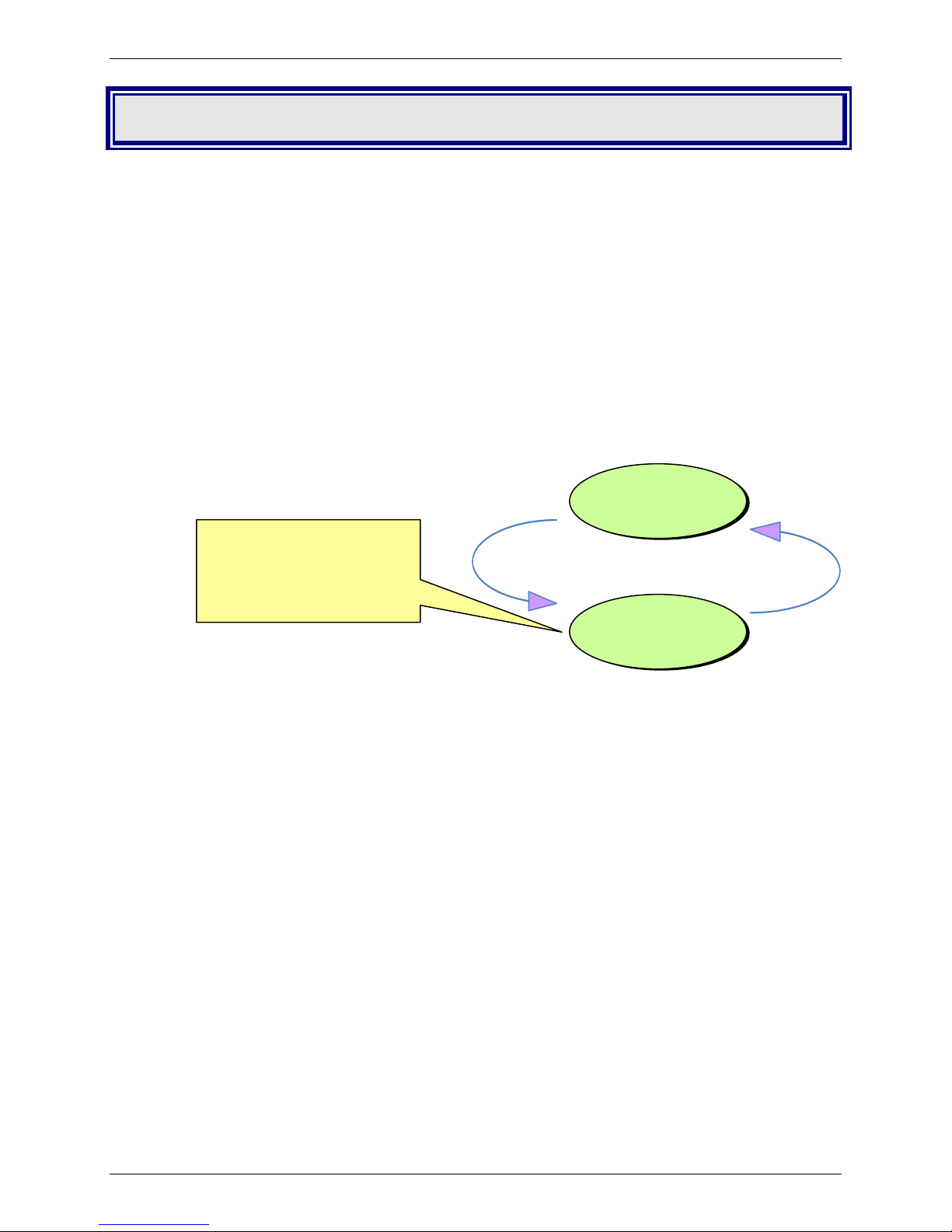
Principles
WIPSoft is an Open AT® application that implements the TCP/IP protocols using custom AT
commands. This Open AT® application operates in co-operative mode and must be downloaded to
the Wavecom Wireless CPU®. The commands are sent from an external application and the
corresponding responses are sent back from the Wavecom Wireless CPU® to the external
application. WIPSoft uses the APIs provided by wipLib and provides custom AT command interface to
the external application.
AT+WIP commands involve:
• A host computer, which issues AT+WIP commands
• Wavecom’s wireless CPU®
• The rest of the Internet / Intranet
Host
CPU
AT Commands
UART INTERNET
Wavecom
WCPU
Multi-Tech Systems, Inc. IP Connectivity AT Commands for GPRS-F4 Wireless Modems (PN S000437E) 5
Page 6

Chapter 1 – Introduction
Multiplexing: Several sockets can be operating at once. The +WIPDATA command allows to
temporarily identify the UART in data mode with a given socket. The data written on UART is
transferred through the socket. The data which arrives on the socket can be read from the
UART. In AT mode, the host receives an unsolicited event when the data arrives on the socket.
Multiple UARTs: There can be several UARTs simultaneously active at once, and different
UARTs can map a different socket simultaneously. However, you cannot map a single socket
on several UARTs simultaneously.
Socket Identification
Sockets are identified by a pair of numbers: the first one identifies the protocol; the second one
identifies a given socket of this protocol.
Possible Protocols
The possible protocols are:
• 1 = UDP
• 2 = TCP in connect mode (Client)
• 3 = TCP in listen mode (Server)
• 4 = FTP
• 5 = HTTP
• 6 = SMTP
• 7 = POP3
Two pairs with a different protocol number but the same index identify two distinct sockets.
Example: Both 1,7 and 2,7 are valid identifiers simultaneously; the former identifies a UDP socket
and the later, a TCP connected socket.
Number of Sockets
The number of sockets per protocol is limited.
• UDP: 8 sockets
• TCP Clients: 8 sockets
• TCP Servers: 4 sockets
Getting Started
Open the TCP/IP Stack
Use the following command to open the TCP/IP stack:
AT+WOPEN=1 Open the TCP/IP Stack
If WOPEN is set to 0, the TCP/IP stack is not opened. In some instances, this may be the
default setting.
Multi-Tech Systems, Inc. IP Connectivity AT Commands for GPRS-F4 Wireless Modems (PN S000437E) 6
Page 7

Chapter 2 – General Configuration AT Commands
Chapter 2 – General Configuration AT
Commands
Important Note: Before you can use any of these commands, you must open the TCP/IP stack. Use the
following command: AT+WOPEN=1 Open the TCP/IP Stack
IP Stack Handling +WIPCFG
Description: The +WIPCFG command is used for performing the following operations:
• Starts TCP/IP stack
• Stops TCP/IP stack
• Configures TCP/IP stack
• Displays version information
Description Notes:
• This command can be used even if the SIM card is absent.
• The +WIND indication from which this command is allowed is 3, which
provides information about the SIM presence after a software reset and also
indicates whether the SIM is inserted or removed. See Appendix A –
GSM/GPRS +WIND AT Command.
Command Syntax: If <mode>=0, 1 AT+WIPCFG=<mode>
Response OK
If <mode>=2 AT+WIPCFG=<mode>,<opt num>,<value>
Response OK
If <mode>=3 AT+WIPCFG=<mode>
Response WIP soft vXX.YY.ZZ on Open AT OS vA.B
OK
If <mode>=4 AT+WIPCFG=<mode>,<action>
Response OK
Read Syntax: AT+WIPCFG? Response <optnum> and <value>
Test Syntax: AT+WIPCFG=? Response OK
Parameters/Defined Values:
<mode> Requested Operation
0 stop TCP/IP stack
1 start TCP/IP stack
2 configure TCP/IP stack
3 display TCP/IP application version
4 TCP/IP stack configuration management
<opt num> Configuration Option Identifier
0 WIP_NET_OPT_IP_TTL – Default TTL of outgoing data grams
This option is a limit on the period of time or number of iterations or
transmissions that a unit of data can experience before it should be
discarded. The time to live (TTL) is an 8-bit field in the Internet Protocol
(IP) header. It is the 9th octet of 20. The default value of this parameter is
64. Its value can be considered as an upper bound on the time that an IP
datagram can exist in an internet system. The TTL field is set by the
sender of the datagram, and reduced by every host on the route to its
destination. If the TTL field reaches zero before the datagram arrives at its
destination, then the datagram is discarded. This is used to avoid a
situation in which an undelivered datagram keeps circulating in the
network.
Range: 0-255 (default value: 64)
Multi-Tech Systems, Inc. IP Connectivity AT Commands for GPRS-F4 Wireless Modems (PN S000437E) 7
Page 8

Chapter 2 – General Configuration AT Commands
IP Stack Handling +WIPCFG Continued
1 WIP_NET_OPT_IP_TOS – Default TOS of outgoing parameters.
The IP protocol provides a facility for the Internet layer to know about the
various tradeoffs that should be made for a particular packet. This is
required because paths through the Internet vary widely in terms of the
quality of service provided. This facility is defined as the "Type of Service"
facility, abbreviated as the "TOS facility".
The TOS facility is one of the features of the Type of Service octet in the IP
datagram header. The Type of Service octet consists of following three
fields:
0 1 2 3 4 5 6 7
+-----+-----+-----+-----+-----+-----+-----+-----+
| | | |
| PRECEDENCE | TOS | MBZ |
| | | |
+-----+-----+-----+-----+-----+-----+-----+-----+
The first field is "PRECEDENCE". It is intended to denote the importance
or priority of the datagram.
The second field is "TOS" which denotes how the network should maintain
the tradeoffs between throughput, delay, reliability, and cost.
The last field is "MBZ" (Must Be Zero"), is currently unused and is set to 0.
The TOS field can have the following values:
1000 -- minimize delay
0100 -- maximize throughput
0010 -- maximize reliability
0001 -- minimize monetary cost
0000 -- normal service
Range: 0-255 (default value: 0)
2 WIP_NET_OPT_IP_FRAG_TIMEO – Time to live in seconds of
incomplete fragments.
When a datagram’s size is larger than the MTU (Maximum Transmission
Unit) of the network, then the datagram is divided into smaller fragments.
These divided fragments are sent separately. The
“WIP_NET_OPT_IP_FRAG_TIMEO” option specifies the Time to live for
these fragments.
Range: 1-65535 (default value: 60)
3 WIP_NET_OPT_TCP_MAXINITWIN – Number of segments of initial
TCP window.
This option is used to specify the number of segments in the initial TCP
window.
A TCP window specifies the amount of outstanding (unacknowledged by
the recipient) data a sender can send on a particular connection before it
gets an acknowledgment back from the receiver. The primary reason for
the window is congestion control.
Range: 0-65535 (default value: 0)
4 WIP_NET_OPT_TCP_MIN_MSS – Default MSS of off-link connections
This option is used by the Open AT Plug-in WIP Lib internally. This
parameter specifies the maximum size of TCP segment which would be
sent. By default, the value of this parameter is set to 536. Hence Open AT
Plug-in WIP Lib would not send any TCP segment having a length greater
than 536 bytes without header.
Range: 536-1460 (default value: 536)
Multi-Tech Systems, Inc. IP Connectivity AT Commands for GPRS-F4 Wireless Modems (PN S000437E) 8
Page 9

Chapter 2 – General Configuration AT Commands
IP Stack Handling +WIPCFG Continued
5 WIP_NET_OPT_DEBUG_PORT
This option is used to specify the port on which the debug traces are to be
sent.
Range: 0-3 (default value: 0)
6 WIP_NET_OPT_SOCK_MAX – Total number of sockets (TCP and
UDP)
This option specifies the maximum number of TCP and UDP sockets that
can be created at one particular time.
Range: 1-23 (default value: 20)
7 WIP_NET_OPT_BUF_MAX – Total number of network buffers
The total number of network buffers which will be used that can be
specified using this option.
Range: 4-42 (default value: 32)
8 WIP_NET_OPT_IP_MULTI_MAX – Total number of multicast group
Caution: The option WIP_NET_OPT_IP_MULTI_MAX is read only
parameter.
Multicast is the delivery of information to a group of destinations
simultaneously, using the most efficient strategy to deliver the messages
over each link of the network only once. IP Multicast is a technique for
many-to-many communication over an IP infrastructure. An IP Multicast
group address is used by sources and the receivers to send and receive
content. Sources use the group address as the IP destination address in
their data packets. Receivers use this group address to inform the network
that they are interested in receiving packets sent to that group. For
example, if some content is associated with group 239.1.1.1, the source
will send data packets destined to 239.1.1.1. Receivers for that content
will inform the network that they are interested in receiving data packets
sent to the group 239.1.1.1. This option is used to set the total number of
multicast group.
9 WIP_NET_OPT_IP_ROUTE_MAX – Size of IP routing table
The Routing tables refer to a database on a router which is used to store
that routers' information on the topology of the network. This option is used
to specify the size of the routing table.
Range: 0-2730 (default value: 0)
10 WIP_NET_OPT_RSLV_QUERY_MAX – Maximum number of DNS
resolver queries
This option specifies the maximum number of DNS queries that will be sent
to the DNS server. This option is used if the IP address is specified as
alphanumeric string.
Range: 1-511 (default value: 4)
11 WIP_NET_OPT_RSLV_CACHE_MAX – Size of DNS resolver cache
It allows to set the maximum size of the DNS resolver cache. The size of
the cache is maintained by the WIP library.
Range: 1-292 (default value: 4)
12 AT_WIP_NET_PREF_TIMEOUT_VALUE – Used for TCP sockets to
configure the packet segmentation on IP network side
This option is used to specify the maximum time to wait between two
successive data chunks received from the mapped UART/serial port
(please see +WIPDATA AT command). It allows the application to buffer a
certain amount of data before writing on IP network side.
Each unit in the range represents 100 msec. For example, value 10 for this
option will give a wait time of 1sec (10 *100mesc).
Multi-Tech Systems, Inc. IP Connectivity AT Commands for GPRS-F4 Wireless Modems (PN S000437E) 9
Page 10

Chapter 2 – General Configuration AT Commands
IP Stack Handling +WIPCFG Continued
Default value for AT_WIP_NET_OPT_PREF_TIMEOUT_VALUE option is
0.
This value means that no specific process is done to avoid TCP packets
segmentation: data are written onto IP network without any delay after the
reception of data from the mapped UART/serial port (please see
+WIPDATA AT command). In this case some TCP packets sent on the IP
network may be smaller than TCP_MIN_MSS value.
Setting e.g. a 10 value for this option will make the application to wait at
least 1 second or twice the TCP_MIN_MSS value to be reached before
sending data on IP network. In this case, TCP packets size sent on the IP
network should be equal to at least TCP_MIN_MSS (Default value = 536
bytes).
Range: 0 – 100 (default value: 0)
<action> Requested operation on TCP/IP stack parameter management
0 Configuration storage (when existing) is freed
1 Stores the configuration parameters
<value> Value range for different configuration options
<XX.YY.ZZ> WIP soft release version
<A.B> Open AT® OS release version
Parameter Storage: Only one IP stack configuration set can be saved into the FLASH memory.
• AT+WIPCFG=4,1 is used to store the TCP/IP stack configuration
parameters into the FLASH memory
• AT+WIPCFG=4,0 is used to free the TCP/IP stack configuration storage
Executing AT+WIPCFG=1 will apply default parameters when existing. Still, it is
possible to change option values at run time using
AT+WIPCFG=2,<optnum>,<optvalue>.
Possible Errors: The possible error message is displayed only if “AT+CMEE=1” is activated else
“ERROR” is displayed.
+CMEE AT error
Description
code
800 invalid option
801 invalid option value
802 not enough memory left
820 error writing configuration in FLASH
memory
821 error freeing configuration in FLASH
memory
844 stack already started
850 initialization failed
Multi-Tech Systems, Inc. IP Connectivity AT Commands for GPRS-F4 Wireless Modems (PN S000437E) 10
Page 11

Examples:
Chapter 2 – General Configuration AT Commands
IP Stack Handling +WIPCFG Continued
Command Responses
AT+WIPCFG=1
OK
Note: Start IP Stack
AT+WIPCFG? +WIPCFG: 0,64
+WIPCFG: 1,0
+WIPCFG: 2,60
+WIPCFG: 3,0
+WIPCFG: 4,536
+WIPCFG: 5,0
+WIPCFG: 6,8
+WIPCFG: 7,32
+WIPCFG: 8,0
+WIPCFG: 9,0
+WIPCFG: 10,4
+WIPCFG: 11,4
+WIPCFG: 12,10
OK
AT+WIPCFG=2,0,10
OK
Note: Configure TTL of the IP Stack
AT+WIPCFG?
+WIPCFG: 0,10
+WIPCFG: 1,0
+WIPCFG: 2,60
+WIPCFG: 3,0
+WIPCFG: 4,536
+WIPCFG: 5,0
+WIPCFG: 6,8
+WIPCFG: 7,32
+WIPCFG: 8,0
+WIPCFG: 9,0
+WIPCFG: 10,4
+WIPCFG: 11,4
+WIPCFG: 12,10
OK
AT+WIPCFG=3
Note: Display software version
WIP soft v202 on Open AT OS
v312
Mar 26 2007 11:45:46
WIPlib:v2a07 WIPSoft:v1a12
OK
AT+WIPCFG=0
OK
Note: Stop the TCP/IP Stack
AT+WIPCFG=4,1
OK
Note: Store IP configuration parameters into FLASH
AT+WIPCFG=4,0
OK
Note: Free IP configuration parameters stored in
FLASH
Multi-Tech Systems, Inc. IP Connectivity AT Commands for GPRS-F4 Wireless Modems (PN S000437E) 11
Page 12

Chapter 2 – General Configuration AT Commands
IP Stack Handling +WIPCFG Continued
Notes
It is recommended to change the default settings of the WIP stack using +WIPCFG only when it
is required. Changing the parameter values especially the max number of sockets and the max
TCP buffer size with the high values lead to over consumption of the stack memory which causes
the WIP Soft to crash. Hence, care must be taken when the default settings of the stack is
changed using +WIPCFG command.
Following option values set by +WIPCFG command are taken into consideration at the run time.
The below option values except for AT_WIP_NET_OPT_PREF_TIMEOUT_VALUE will be taken
into consideration at next start up only if these are saved in the flash before stopping the stack.
• WIP_NET_OPT_IP_TTL
• WIP_NET_OPT_IP_TOS
• WIP_NET_OPT_IP_FRAG_TIMEO
• WIP_NET_OPT_TCP_MAXINITWIN
• WIP_NET_OPT_TCP_MIN_MSS
• WIP_NET_OPT_DEBUG_PORT
• AT_WIP_NET_OPT_PREF_TIMEOUT_VALUE
Following option values set by +WIPCFG command are taken into consideration in the next start
up only if these are saved in the flash before stopping the stack.
• WIP_NET_OPT_SOCK_MAX
• WIP_NET_OPT_BUF_MAX
• WIP_NET_OPT_IP_ROUTE_MAX
• WIP_NET_OPT_RSLV_QUERY_MAX
• WIP_NET_OPT_RSLV_CACHE_MAX
Multi-Tech Systems, Inc. IP Connectivity AT Commands for GPRS-F4 Wireless Modems (PN S000437E) 12
Page 13

Chapter 2 – General Configuration AT Commands
Bearers Handling +WIPBR
Bearers Handling +WIPBR
Description: The +WIPBR command can be used to:
• Select the bearer
• Start/close the bearer
• Configure different bearer options such as access point name
Description Notes:
• The SIM card must be inserted in order to use this command.
• This command can be used even if the PIN 1/CHV 1 is not entered.
• This command can be used even if the PIN 2/CHV 2 is not entered.
Command Syntax: If <cmdtype>=0,1 or 5 AT+WIPBR=<cmdtype>,<bid>
Response OK
If <cmdtype>=2 AT+WIPBR=<cmdtype>,<bid>,<opt num>,<value>
Response OK
If <cmdtype>=3 AT+WIPBR=<cmdtype>,<bid>,<opt num>
Response OK
If <cmdtype>=4 AT+WIPBR=<cmdtype>,<bid>,<mode>[,<login>,
<password>,[<caller identity>]]
Response OK
If <cmdtype>=6 AT+WIPBR=<cmdtype>,<bid>,<mode>
Response OK
Read Command: AT+WIPBR? Reads current values.
Response <bid>,<state>
[<bid>,<state>[..]]
OK
Test Command: AT+WIPBR=? Lists available values
Response OK
Unsolicited Response: If <mode>=1 +WIPBR: <bid>,<status>,<local IP @>,<remote IP @>,<DNS1
@>, <DNS2 @>
Parameters/
Defined Values: <cmd type> Type of Command
0 close bearer
1 open bearer
2 set value of different bearer options
3 get value of different bearer options
4 start bearer
5 stop bearer
6 bearer configuration management
<bid> Bearer Identifier
1 UART1
2 UART2
3 N/A
4 N/A
5 GSM
6 GPRS
11..14 CMUX port over UART1
21..24 CMUX port over UART2
<opt num> Bearer Option Identifier
0 WIP_BOPT_LOGIN
username (string)
max: 64 characters
1 WIP_BOPT_PASSWORD
password (string)
max: 64 characters
Multi-Tech Systems, Inc. IP Connectivity AT Commands for GPRS-F4 Wireless Modems (PN S000437E) 13
Page 14

Chapter 2 – General Configuration AT Commands
Bearers Handling +WIPBR continued
2 WIP_BOPT_DIAL_PHONENB
phone number (string)
max: 32 characters
5 WIP_BOPT_DIAL_RINGCOUNT
Number of rings to wait before sending the
WIP_BEV_DIAL_CALL event
range: 0-65535
6 WIP_BOPT_DIAL_MSNULLMODEM
Enable MS-Windows null-modem protocol ("CLIENT"/"SERVER"
handshake)
range: 0-1
7 WIP_BOPT_PPP_PAP
Allow PAP authentication
range: 0-1
8 WIP_BOPT_PPP_CHAP
Allow CHAP authentication
range: 0-1
9 WIP_BOPT_PPP_MSCHAP1
Allow MSCHAPv1 authentication
range: 0-1
10 WIP_BOPT_PPP_MSCHAP2
Allow MSCHAPv2 authentication
range: 0-1
11 WIP_BOPT_GPRS_APN
Address of GGSN (string)
max: 96 characters
12 WIP_BOPT_GPRS_CID
CID of the PDP context
range: 1-4
13 WIP_BOPT_GPRS_HEADERCOMP
Enable PDP header compression
range: 0-1
14 WIP_BOPT_GPRS_DATACOMP
Enable PDP data compression
range: 0-1
15 WIP_BOPT_IP_ADDR
Local IP address (IP/string)
16 WIP_BOPT_IP_DST_ADDR
Destination IP address (IP/string)
17 WIP_BOPT_IP_DNS1
Address of primary DNS server
(IP/string)
18 WIP_BOPT_IP_DNS2
Address of secondary DNS server
(IP/string)
19 WIP_BOPT_IP_SETDNS
Configure DNS resolver when connection is established
range: 0-1
20 WIP_BOPT_IP_SETGW
Set interface as default gateway when connection is established
range: 0-1
<value>: range of value for different bearer options
<mode>: mode of operation
0 client
1 server
<state>: current state of the bearer
0 stopped
1 started
Multi-Tech Systems, Inc. IP Connectivity AT Commands for GPRS-F4 Wireless Modems (PN S000437E) 14
Page 15

Chapter 2 – General Configuration AT Commands
Bearers Handling +WIPBR Continued
<status>: result of the connection process
0 successful
any other value: to be matched to error code value (e.g., “814”
means PPP authentication failure)
<local IP @*>: local IP address
<remote IP @*>: remote IP address. (first node in internet)
<DNS1 IP @*>: Domain Name Server address
<DNS2 IP @*>: Domain Name Server address
<login>: PPP login
<passwd>: PPP password
<caller identity>: optional ASCII string (type ascii*).
If not specified, then target will accept all DATA calls
(independently of caller identification). If specified, then target
will only accept calls from <caller identity> (which are the GSM
data call number of the GSM client).
*IP @ are displayed in alpha numeric dot format. e.g. 192.168.0.1…When no IP
address is known, “0.0.0.0“ is displayed.
Caution: The options WIP_BOPT_IP_DST_ADDR, WIP_BOPT_IP_DNS1 and
WIP_BOPT_IP_DNS2 are “read only” for GPRS/GSM client
Parameter Storage
Several bearer configuration set can be saved.
Calling twice AT+WIPBR=6,<bid>,1 with the same <bid> will store the last
configuration set.
• AT+WIPBR=6,<bid>,1 is used to store the bearer configuration parameters set
associated with the bearer <bid> into the FLASH memory.
• AT+WIPBR=6,<bid>,0 is used to free the bearer configuration parameters set
associated with the bearer <bid>.
Executing AT+WIPBR=1,<bid> will open bearer <bid> with default parameters of
the bearer when existing.
Possible Errors
The possible error message is displayed only if “AT+CMEE=1” is activated else
“ERROR” is displayed.
+CMEE AT
Description
error code
800 invalid option
801 invalid option value
802 not enough memory left
803 already open
804 not available on this platform
807 bearer connection failure: line busy
808 bearer connection failure: no answer
815 bearer connection failure: PPP authentication failed
816 bearer connection failure: PPP IPCP negotiation failed
820 error writing configuration in FLASH memory
821 error freeing configuration in FLASH memory
Multi-Tech Systems, Inc. IP Connectivity AT Commands for GPRS-F4 Wireless Modems (PN S000437E) 15
Page 16

Examples
Command Responses
AT+WIPBR? 1,0
AT+WIPBR? OK
AT+WIPBR=1,6
Note: Open GPRS bearer
AT+WIPBR=2,6,11,”APN name”
Note: Set APN of GPRS bearer
AT+WIPBR=3,6,11
Note: Get APN of GPRS bearer
AT+WIPBR=4,6,0
Note: Start GPRS bearer
AT+WIPBR=5,6
Note: Stop GPRS bearer
AT+WIPBR=0,6
Note: Close GPRS bearer
AT+WIPBR=1,5
Note: Open GSM bearer
AT+WIPBR=2,5,0,"login"
Note: Set the login for GSM bearer
AT+WIPBR=2,5,1,"password"
Note: Set the password for GSM bearer
AT+WIPBR=2,5,2,"phonenumber"
Note: Set the phone number for GSM bearer
AT+WIPBR=2,5,15,"1.1.1.1"
Note: Set the local IP address for GSM bearer
AT+WIPBR=2,5,16,"2.2.2.2"
Note: Set the destination IP address for GSM
bearer
AT+WIPBR=3,5,15
Note: Read the local IP address for GSM bearer
AT+WIPBR=3,5,16
Note: Read the destination IP address for GSM
bearer
AT+WIPBR=4,5,0
Note: Start the GSM bearer as a client
AT+WIPBR=3,5,15
Note: Read the local IP for GSM bearer
AT+WIPBR=3,5,16
Note: Read the destination IP for GSM bearer
AT+WIPBR=5,5
Note: Stop the GSM bearer
AT+WIPBR=0,5
Note: Close the GSM bearer
Chapter 2 – General Configuration AT Commands
Bearers Handling +WIPBR Continued
6,1
OK
Note: Bearer UART1 is open but not
started bearer GPRS is open and
started
Note: No bearer has been opened yet
OK
OK
+WIPBR: 6,11,”APN name”
OK
OK
OK
OK
OK
OK
OK
OK
OK
OK
+WIPBR: 5,15,"0.0.0.0"
OK
Note: Local IP address is not set as
GSM bearer and is still not connected
+WIPBR: 5,16,"0.0.0.0"
OK
Note: Destination IP address is not set
as GSM bearer and is still not
connected
OK
+WIPBR: 5,15,"1.1.1.1"
OK
+WIPBR: 5,16,"2.2.2.2"
OK
OK
OK
Multi-Tech Systems, Inc. IP Connectivity AT Commands for GPRS-F4 Wireless Modems (PN S000437E) 16
Page 17

Chapter 2 – General Configuration AT Commands
Bearers Handling +WIPBR Continued
Notes:
Starting a Bearer
The mandatory parameters to start a bearer in
• server mode: <cmdtype>, <bid>, <mode>, <login> and <password>
• client mode: <cmdtype>, <bid> and <mode>
Depending on the mode and the bearer type, additional parameters are required or forbidden:
Bid Mode Other Parameters
1,3,11,14,21,24 0 None
1,3,11,14,21,24 1 <PPP login>, <PPP password>
5 0 None
5 1 <login>,<password>[,<caller identity>]
6 0 None
Starting bearer as a server requires additional parameters as mentioned in the above table.
• For PPP server, only parameters <login> and <password> are required. They will be
compared with remote PPP client login and password.
• For GSM server, <login> and <password> will be used for PPP over GSM establishment
(same behavior as described for PPP server).
The <caller identity> is an optional ASCII string (type ASCII*). If not specified, then target will accept
all DATA calls (independently of caller identification). If specified, then target will only accept calls
from <caller identity> (which is the GSM data call number of the GSM client.
Opening bearer only consists in associating the IP protocol stack with the specified bearer. The
corresponding bearer setup has to be done through the adequate already existing AT commands
(please refer to +WMFM commands for UART1 and UART2, +CMUX command for CMUX virtual
ports and GSM/GPRS AT commands).
Several bearers can be opened at the same time but only one bearer can be started at a time.
If both DNS1 and DNS2 are displayed as “0.0.0.0” in the unsolicited message when bearer is opened
in server mode, it means that connecting to a remote IP host through an URL will fail.
The options WIP_BOPT_DIAL_REDIALCOUNT and WIP_BOPT_DIAL_REDIALDELAY will not be
implemented through AT commands. Nevertheless, for future compatibility reason, Opt num 3 and 4
are kept as reserved.
For GSM bearer, the options WIP_BOPT_IP_ADDR and WIP_BOPT_IP_DST_ADDR will display
valid addresses only when the bearer is started and connected; otherwise, it will display an address
"0.0.0.0".
Multi-Tech Systems, Inc. IP Connectivity AT Commands for GPRS-F4 Wireless Modems (PN S000437E) 17
Page 18
Chapter 3 – IP Protocol Services
Chapter 3 – IP Protocol Services
Service Creation +WIPCREATE
Description: The +WIPCREATE command is used to create UDP, TCP client and TCP server
sockets associated with the specified index and FTP/HTTP/SMTP/POP3 service.
Only one FTP/HTTP/SMTP/POP3 session at a time is available.
If a local port is specified while creating a socket, the created socket will be
assigned to this port; if not, a port will be assigned dynamically by WIP application.
If peer IP and peer port is specified, the created socket will be connected to the
specified IP and port.
TCP server cannot be used to transfer data. To transfer data, it creates a local TCP
client socket. This process of creating local socket is referred as “spawning”. When
a server socket is created using, socket passively listens on a specified port for
incoming connections. The below mentioned diagram shows different states
managed for TCP server.
Closed
Server listening to the
remote socket for connect
request
On reception of a connection request from a remote client socket, a server socket
does the following:
• Spawns a new socket (client) to connect to the remote socket
• Data transfer is done between the spawned socket and the remote socket
• Server socket remains in the listening mode and is ready to accept the
request from other clients
Description Notes:
• A SIM card must be inserted in order to use this command.
• The PIN 1/CHV 1 code must be entered to use this command.
• The PIN 2/CHV 2 does not have to be entered to use this command.
• The +WIND general indication command value from which +WIPCREATE
is allowed is 4. This value (4) indicates that the product is ready to process
AT commands (except phonebooks, AOC, SMS), but is still in emergency
mode. See Appendix A – GSM/GPRS +WIND AT Command.
Server Socket
Create
Close Server
Socket channel
Listen
Multi-Tech Systems, Inc. IP Connectivity AT Commands for GPRS-F4 Wireless Modems (PN S000437E) 18
Page 19
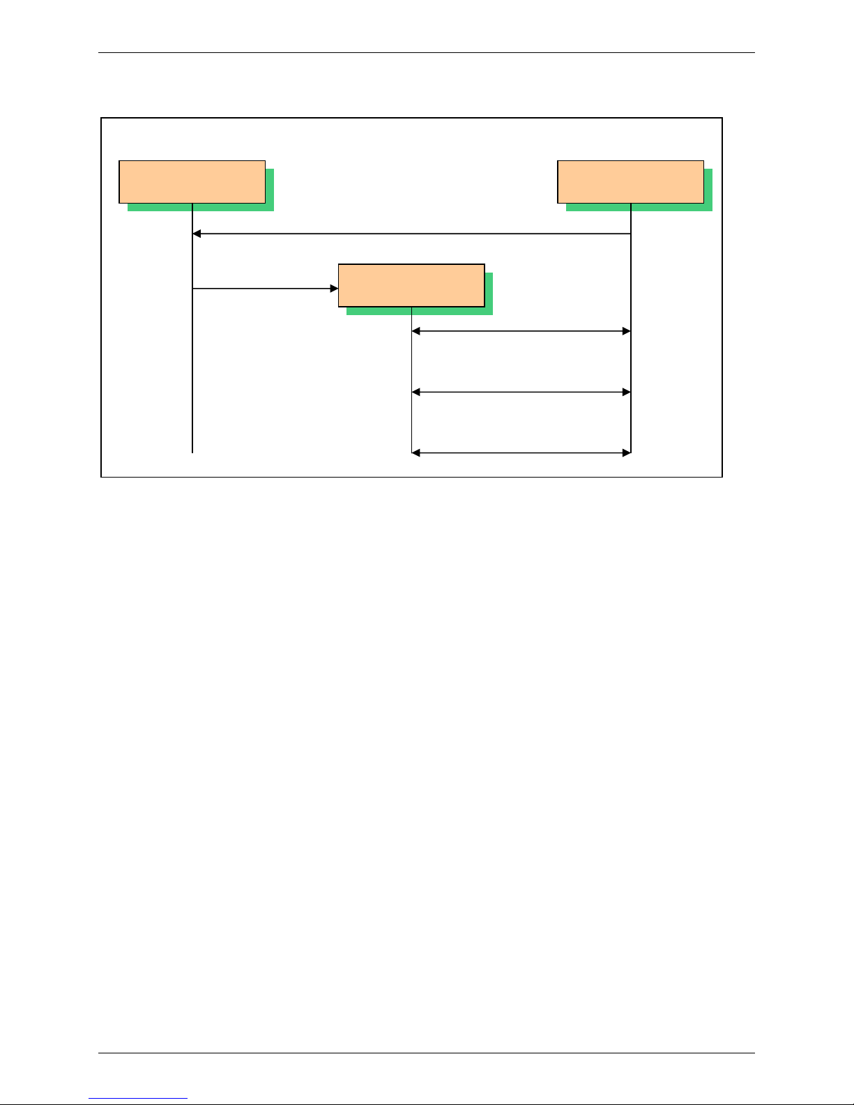
Chapter 3 – IP Protocol Services
Service Creation +WIPCREATE Continued
This diagram shows how to establish a connection.
Server Socket Client Socket
Connect request
Spawn a new
socket
Client Socket
Spawned
Connected
Transfer data
Socket
Closed
Command Syntax: For a definition of <mode>, see Parameter/Defined Values on the next page.
If <mode>=1:
AT+WIPCREATE=<mode>,<communication index>,[<local port>] [,<peer IP>,<peer port>]
Response OK
If <mode>=2
AT+WIPCREATE=<mode>,<communication index>,<peer IP>,<peer port>
Response OK
If <mode>=3
AT+WIPCREATE=<mode>,<server index>,<local port>,<from idx>,<to idx>
Response OK
If <mode>=4
AT+WIPCREATE=<mode>,<index>,<server>[,<peer_port>],<username>, <password>
[,<account>]
Response OK
If <mode>=5
AT+WIPCREATE=<mode>,<index>,[<server>[,<peer port>]][,<username>,<password>]
[,<header list>[...]]]
Response OK
If <mode>=6 or 7
AT+WIPCREATE=<mode>,<index>,<server>[,<peer port>][,<username>,<password>]
Response OK
Read Command: AT+WIPCREATE? Displays current values.
Response OK
Test Command: AT+WIPCREATE=? Displays available values.
Response OK
Unsolicited Response: If <mode>=1 or 2
+WIPREADY: <mode>,<communication index>
If <mode>=3
+WIPACCEPT: <server index>,<communication idx>
If <mode>=5, 6 or 7
+WIPREADY: <mode>,<index>
Multi-Tech Systems, Inc. IP Connectivity AT Commands for GPRS-F4 Wireless Modems (PN S000437E) 19
Page 20

Service Creation +WIPCREATE Continued
Parameters/Defined Values:
<mode>: Specifies Type of Socket
1 UDP
2 TCP Client
3 TCP Server
4 FTP
5 HTTP Client
6 SMTP Client
7 POP3 Client
<index>: TCP/UDP/FTP/HTTP/SMTP/POP3 Session Identifier
<local port>: Local TCP/UDP Port
<peer IP>: Peer IP Address; a string between quotes indicating an address either
in numeric form (e.g. “85.12.133.10”) or as a DNS entry (e.g.
“www.wavecom.com”)
<peer port>: Peer Port or the Server Port
For TTCP/UDP, this parameter is the port of the peer socket
For FTP,HTTP,SMTP and POP3, this parameter is the server port
Range: 1-65535 (Default Value for FTP: 21)
(Default Value for HTTP: 80)
(Default Value for SMTP: 25)
(Default Value for POP3: 110)
<from idx>: Minimum Index for Spawned TCP Sockets
Range: 1-8
<server index>: TCP Server Socket Identifier
Range: 1-4
<to idx>: Maximum Index for Spawned TCP Sockets
Range: 1-8
<communication index>: Indexes Reserved for Spawned Sockets
It cannot be used by other sockets even if the spawned sockets are not
created yet.
Range: 1-8
<server>: Server Address or Proxy Address
This parameter is the server address for FTP, SMTP and POP3 protocol
and for HTTP it is proxy server address.
It can either be a 32 bit number in dotted-decimal notation
(“xxx.xxx.xxx.xxx”) or an alpha numeric string format for hostname.
<user name>: Username for the Authentication in String Format
Authentication is disabled when this parameter is not specified for HTTP,
SMTP and POP3.
<password>: Password for the Authentication in String Format
Authentication is disabled when this parameter is not specified for HTTP,
SMTP and POP3.
<account>: Account Information of the User in String Format
This is required by some FTP server during authentication phases.
<header list>: HTTP Header Message (name-value pair)
The first string in the message header field is the name of the header
and the second string is the value of the header.
<…> Additional HTTP message header fields.
More pairs (name, value) of HTTP message header field can be added.
Parameter Storage: None
Chapter 3 – IP Protocol Services
Multi-Tech Systems, Inc. IP Connectivity AT Commands for GPRS-F4 Wireless Modems (PN S000437E) 20
Page 21

Possible Errors:
+CMEE” AT error code Description
3 operation not allowed
800 invalid option
803 operation not allowed in the current WIP stack state
830 bad index
832 bad port number
834 not implemented
836 memory allocation error
837 bad protocol
839 error during channel creation
840 UDP/TCP socket or FTP/HTTP/SMTP/POP3 session is
842 destination host unreachable (whether host unreachable,
845 Attempt is made to reserve/create a client socket which is
860 Protocol undefined or internal error
861 User name rejected by server
862 Password rejected by server
865 Authentication error
866 Server not ready error
Chapter 3 – IP Protocol Services
Service Creation +WIPCREATE Continued
already active
Network unreachable, response timeout)
already reserved/opened by TCP server/client
Multi-Tech Systems, Inc. IP Connectivity AT Commands for GPRS-F4 Wireless Modems (PN S000437E) 21
Page 22

Service Creation +WIPCREATE Continued
Examples:
Command Responses
AT+WIPCREATE=1,1,80
Note: Create the UDP socket on local port 80 with
communication index = 1 Ù Wireless CPU® acts
as an UDP server awaiting for incoming datagram
OK
Note: An unsolicited event +WIPREADY:
1,1 will be received once the UDP socket is
ready for usage
on local port 80
AT+WIPCREATE=1,1,”www.wavecom.com”,80
Note: Create the UDP socket on arbitrary free local
port with peer IP and peer port 80 with
communication index = 1 Ù Wireless CPU® acts
OK
Note: An unsolicited event +WIPREADY:
1,1 will be received once the UDP socket is
ready for usage
as a UDP client that can send datagram towards
the remote entity
AT+WIPCREATE=1,1,80,”www.wavecom.com”,8
0
Note: Create the UDP socket on local port 80 with
peer IP and peer port 80 with communication index
OK
Note: An unsolicited event +WIPREADY:
1,1 will be received once the UDP socket is
ready for usage
= 1 Ù Wireless CPU® acts as a UDP client and an
UDP server : it can send datagram towards the
remote entity and receiving datagram on the
specified local port.
AT+WIPCREATE=3,1,80,5,8
Note: Create the TCP server on port 80 with server
index=1 Ù Wireless CPU® acts as a TCP server: it
will from now on spawn TCP client socket from
OK
Note: An unsolicited event +WIPACCEPT:
1,5 will be received once the TCP server is
ready for usage
communication index 5 to 8
AT+WIPCREATE=2,1,”IP ADDR”,80
Note: Create the TCP client on port 80 with index=1
Ù Wireless CPU® acts as a TCP client : it can from
now on communicate with the remote specified
OK
Note: An unsolicited event +WIPREADY:
2,1 will be received once the TCP client is
ready for usage
entity through communication index 1
Chapter 3 – IP Protocol Services
AT+WIPCREATE=4,1,”ftp.wavecom.com”,”admi
n”,”123456”
Note: Create a FTP session Ù towards the remote
specified FTP server. Communication index to be
used then is 1
AT+WIPCREATE=5,1,”proxyaddress”,,”user
name”,”password”,”User-Agent”,”WIP-HTTPClient/1.0”,"Accept-Encoding","gzip","AcceptLanguage","en-US"
AT+WIPCREATE=5,1,“proxyaddress“,,”user”,”pa
ss”
OK
OK
+WIPREADY: 5, 1
Note: HTTP session with proxy and 3
message header fields
Use default 80 proxy port number
3 message header fields:
Message header field name is “User-Agent”
and header field value is “WIP-HTTTP-
Client/1.0”
Message header field name is “Accept-
Encoding” and header field value is “gzip”
Message header field name is “Accept-
Language” and header field value is “en-
US”
OK
+WIPREADY: 5, 1
Note: Authentication connection on default
proxy server port 80
Multi-Tech Systems, Inc. IP Connectivity AT Commands for GPRS-F4 Wireless Modems (PN S000437E) 22
Page 23

Chapter 3 – IP Protocol Services
Service Creation +WIPCREATE Continued
AT+WIPCREATE=6,1,"smtp.mail.yahoo.fr",
"587","user","pass"
OK
+WIPREADY: 6, 1
Note: Connect to SMTP server port 587 with
given username and password.
AT+WIPCREATE=7,1,"192.168.1.4","110",
"user","pass"
OK
+WIPREADY: 7, 1
Note: Connect to POP3 server port 110 with
given username and password.
AT+WIPCREATE=7,1, "pop.mail.server.com"
OK
+WIPREADY: 7, 1
Note: Connect to the default port 110 of
POP3 server.
No authentication required
Notes:
The maximum number of sockets can be set to 23 so that WIP soft can handle in the same time either
one FTP session (in passive mode)/HTTP/SMTP/POP3, 8 UDP sockets, 8 TCP client sockets and 4 TCP
servers.
Starting a TCP server requires to specify the maximum number of communication sockets that can be
spawned. This can be done using <from idx> and <to idx> parameters. Note that the value set for <to
idx> should be equal or more than <from idx>.
The maximum communication socket that can be created using WIP Soft is 8. Hence, the range for
<communication index> and <from idx>, <to idx> is 1-8. Note that the spawned communication socket
and the TCP client socket share the same communication index.
It is not possible to create a client socket with AT+WIPCREATE=2, x, y, z when x is already reserved by a
server with AT+WIPCREATE=3,<server idx>, <local port>,a,b where a≤x≤b. Similarly, it is not possible to
reserve a range with AT+WIPCREATE=3, <server idx>, <local port>, a, b if one of the TCP client socket
indexes between a and b is already reserved, be it by a client or a server range
When no more communication index is available in the TCP server’s range (or no more resources to
accept new incoming connections), any peer trying to connect to the server will receive an accept ()
immediately followed by a shutdown () (“peer close”)."
The +WIPCREATE command causes the connection and authentication to the FTP server. If several file
uploads and retrievals are required to/from the same server, a single connection with +WIPCREATE is
needed. Then, each file operation will be done (one +WIPFILE command per operation), and the FTP
connection will be released with +WIPCLOSE.
SIM card is required only if FTP session is established through GSM or GPRS. An FTP session upon an
UART will work without a SIM card.
Multi-Tech Systems, Inc. IP Connectivity AT Commands for GPRS-F4 Wireless Modems (PN S000437E) 23
Page 24

Chapter 3 – IP Protocol Services
Closing a Service +WIPCLOSE
Closing a Service +WIPCLOSE
Description: The +WIPCLOSE command is used to close a socket or FTP/HTTP/SMPT/POP3
session. When one serial port (UART or CMUX DLCI) is used to map a socket for
read/write operations, an [ETX] character can also be used to close the socket.
An unsolicited event is generated, when socket or FTP/HTTP/SMPT/POP3 session
is closed.
Description Notes:
• The SIM card must be inserted in order to use this command.
• The PIN 1/ CHV 1 code must be entered in order to use this command.
• The PIN 2/CHV 2 code does not have to be entered in order to use this
command.
• The +WIND general indication command value from which +WIPCREATE is
allowed is 4. This value (4) indicates that the product is ready to process AT
commands (except phonebooks, AOC, SMS), but is still in emergency mode.
See Appendix A – GSM/GPRS +WIND AT Command.
Command Syntax: AT+WIPCLOSE=<protocol>,<idx>
Response OK
Read Command: AT+WIPCLOSE?
Response None
Test Command: AT+WIPCLOSE=?
Response OK
Unsolicited Response: +WIPPEERCLOSE: <protocol>,<idx>
Parameters/Defined Values:
<protocol>: protocol type
1 UDP
2 TCP client
3 TCP server
4 FTP
5 HTTP
6 SMTP
7 POP3
<idx>: socket identifier or FTP/HTTP/SMPT/POP3 session identifier
This parameter is the index of the socket or
FTP/HTTP/SMTP/POP3 session created with +WIPCREATE
command.
Parameter Storage: None
Possible Errors:
“+CMEE”
AT error
code
802 not enough memory
803 operation not allowed in the current
830 bad index
831 bad state
834 not implemented
837 bad protocol
Description
WIP stack state
Multi-Tech Systems, Inc. IP Connectivity AT Commands for GPRS-F4 Wireless Modems (PN S000437E) 24
Page 25

Examples:
Command Responses
AT+WIPCLOSE=1,1
Note: Close UDP socket with
OK
communication index 1
AT+WIPCLOSE=2,1
Note: Close TCP client with communication
OK
index 1
AT+WIPCLOSE=3,1
Note: Close TCP server with communication
OK
index 1
AT+WIPCLOSE=4,1
Note: Close FTP session with index 1
OK
Note: An unsolicited event +WIPPEERCLOSE: 4,1
is received once the FTP session is closed
AT+WIPCLOSE=5,1
OK
Note: Close HTTP session with index 1
AT+WIPCLOSE=6,1
OK
Note: Close SMTP session with index 1
AT+WIPCLOSE=7,1
OK
Note: Close POP3 session with index 1
Notes:
Chapter 3 – IP Protocol Services
Closing a Service +WIPCLOSE Continued
After issuing +WIPCLOSE command, no more data can be sent and received over the socket/session. In
case of FTP protocol, the closure of FTP session is indicated by +WIPEERCLOSE unsolicited response
when +WIPCLOSE command is used for closing the session.
Multi-Tech Systems, Inc. IP Connectivity AT Commands for GPRS-F4 Wireless Modems (PN S000437E) 25
Page 26

Chapter 3 – IP Protocol Services
Service Option Handling +WIPOPT
Service Option Handling +WIPOPT
Description: The +WIPOPT command is used to read and/or to configure different parameters
on sockets and FTP/HTTP/SMTP/POP3 service.
Description Notes:
• The SIM card must be inserted in order to use this command
• The PIN 1/CHV 1 code must be entered in order to use this command.
• The PIN 2/CHV 2 code does not have to be entered in order to use this
command.
• The +WIND general indication command value from which +WIPCREATE
is allowed is 4. This value (4) indicates that the product is ready to process
AT commands (except phonebooks, AOC, SMS), but is still in emergency
mode. See Appendix A – GSM/GPRS +WIND AT Command.
Command Syntax: For a definition of <action>, see Parameter/Defined Values below.
If <action>=1 AT+WIPOPT=<protocol>,<idx>,<action>,<optnum>
Response OK
If <action>=2 AT+WIPOPT=<protocol>,<idx>,<action>,<optnum>,<optval>
Response OK
Read Command: AT+WIPOPT? Displays the current values.
Test Command: AT+WIPOPT=? Displays available values.
Unsolicited Response: If <action>=1 Response: +WIPOPT: <protocol>,<optnum>,<optval>
If <action>=1 and <protocol> =5 and <optnum>=54+WIPOPT:
Response: +WIPOPT: 5,54,<message header field name>,
<message header field value>,[…]
Parameters/Defined Values:
<protocol>: protocol type
1 UDP
2 TCP client
3 TCP server
4 FTP
5 HTTP
6 SMTP
7 POP3
<idx>: socket or FTP/HTTP/SMTP/POP3 session identifier
<action>: requested operation
1 read the value of an option
2 write the value of an option
<optnum>: option that can be read/written
<optval>: value of an option
Parameter Storage: None
Possible Errors:
+CMEE AT error code Description
800 invalid option
801 invalid option value
803 operation not allowed in the current WIP stack state
830 bad index
834 not implemented
835 option not supported
837 bad protocol
850 unknown reason
860 protocol undefined or internal error
863 protocol delete error
864 protocol list error
Multi-Tech Systems, Inc. IP Connectivity AT Commands for GPRS-F4 Wireless Modems (PN S000437E) 26
Page 27

Examples:
Chapter 3 – IP Protocol Services
Service Option Handling +WIPOPT continued
Command Responses
AT+WIPOPT=2,1,2,8,20
OK
Note: Set TTL for TCP client
AT+WIPOPT=2,1,1,8
Note: Get TTL for TCP client
AT+WIPOPT=3,1,2,9,10
Note: Set TOS for TCP server
AT+WIPOPT=3,1,1,9
Note: Get TOS for TCP server
AT+WIPOPT=1,1,1,1
Note: Get peer port for UDP
AT+WIPOPT=4,1,2,40,1
Note: Set data representation type for FTP
AT+WIPOPT=4,1,1,40
Note: Get data representation type for FTP
AT+WIPOPT=5,1,2,52,0
Note: Set HTTP version to 1.0
AT+WIPOPT=5,1,2,53,6
Note: Set maxredirect to 6
AT+WIPOPT=5,1,1,52
Note: Get HTTP version
+WIPOPT: 2,1,8,20
OK
OK
+WIPOPT: 3, 9,10
OK
+WIPOPT: 1,1,80
OK
OK
+WIPOPT: 4,1,1
OK
OK
OK
+WIPOPT: 5,52,0
OK
AT+WIPOPT=5,1,1,53
Note: Get maxredirect value
AT+WIPOPT=6,1,2,61,senderaddress@mail.com
+WIPOPT: 5,53,6
OK
OK
Note: Set the sender address
AT+WIPOPT=6,1,2,67,0
OK
Note: The application will format the mail header
and send it during the data sending phase
AT+WIPOPT=6,1,1,61
Note: Get the sender address
+WIPOPT:
6,61,”senderadress@mail.com”
OK
AT+WIPOPT=6,1,1,60
Note: Get last protocol error / status
+WIPOPT:6,60,220,“220 innosoft.com
SMTP service ready”
OK
AT+WIPOPT=6,1,1,66
Note: Get the set mail subject
AT+WIPOPT=7,1,1,72
Note: Get total mail size
AT+WIPOPT=7,1,1,73
Note: Get mail listing
+WIPOPT: 6,66,“My mail subject”
OK
+WIPOPT: 7,72,243000
OK
+WIPOPT: 7,73,”1,1024”
+WIPOPT: 7,73,”2,5237”
+WIPOPT: 7,73,”3,128”
+WIPOPT: 7,73,”4,36400”
+WIPOPT: 7,73,”5,356”
OK
AT+WIPOPT=7,1,2,74,10
Note: Delete mail ID 10
+WIPOPT: 7,74,10
OK
Multi-Tech Systems, Inc. IP Connectivity AT Commands for GPRS-F4 Wireless Modems (PN S000437E) 27
Page 28

Chapter 3 – IP Protocol Services
Service Option Handling +WIPOPT Continued
Notes:
It is possible to change and retrieve an option value using +WIPOPT command only when the
socket/session (given by <idx>) is active or else it returns an error.
Options that can be applied to UDP, TCP Client, TCP Server Sockets
Opt
Num
Value
Format
Meaning UDP TCP Client TCP Server
0 0-65535 WIP_COPT_PORT R R R
1 0-65535 WIP_COPT_PEER_PORT R R 2 string WIP_COPT_PEER_STRADDR R R 3 0-1 WIP_COPT_BOUND R - 4 0-5839 WIP_COPT_SND_LOWAT - RW RW
5 0-5839 WIP_COPT_RCV_LOWAT - RW RW
6 0-65535 WIP_COPT_NREAD R R 7 0-1 WIP_COPT_NODELAY - RW RW
8 0-255 WIP_COPT_TTL RW RW RW
9 0-255 WIP_COPT_TOS RW RW RW
Options that can be applied to an FTP Session
Opt
Num
Value
Format
Value
Type
Meaning
40 0-1 Boolean data representation type.
0: ASCII
1: binary
default: 0
41 0-1 Boolean FTP mode.
0: active
1: passive
default: 1
Option that can be applied to an HTTP Session
Opt
Num
50 u32 WIP_COPT_RCV_BUFSIZE set the size of the TCP
Value
Format
Value
Type
Option Types Meaning Type
RW
socket receive buffer
default value specified by
the TCP channel
51 u32 WIP_COPT_SND_BUFSIZE set the size of the TCP
RW
socket send buffer.
default value specified by
the TCP channel
52 0-1 u8 WIP_COPT_HTTP_VERSION
0: HTTP 1.0
define the HTTP version
to be used by the session
default value is HTTP 1.1
RW
1: HTTP 1.1
53 u32 WIP_COPT_HTTP_MAXREDIRECT set the maximum number
RW
of allowed redirects
a zero value disables
automatic redirects
Default value is 8
54 <ascii
list>
WIP_COPT_HTTP_HEADER return the HTTP message
header field (or a list of
R
message header fields)
from the last WIPFILE call
Caution: Option 54(WIP_COPT_HTTP_HEADER) is not implemented and hence attempt to read this
option will result in +CME ERROR: 834.
Multi-Tech Systems, Inc. IP Connectivity AT Commands for GPRS-F4 Wireless Modems (PN S000437E) 28
Page 29

Chapter 3 – IP Protocol Services
Service Option Handling +WIPOPT Continued
Options that can be applied to an SMTP Session
Opt
Num
60 digit/string u32/ascii WIP_COPT_SMTP_STATUS_CODE get last protocol error
Value
Format
Value Type Option Types Meaning Type
R
code and associated
error string
61 string ascii WIP_COPT_SMTP_SENDER set the sender address RW
62 string ascii WIP_COPT_SMTP_SENDERNAME set the sender name RW
63 string ascii WIP_COPT_SMTP_REC set the recipients list RW
64 string ascii WIP_COPT_SMTP_CC_REC set the CC recipients list RW
65 string ascii WIP_COPT_SMTP_BCC_REC set the BCC recipients
RW
list
66 string ascii WIP_COPT_SMTP_SUBJ set the mail subject RW
67 digit u32 WIP_COPT_SMTP_FORMAT_
HEADER
decide if the SMTP
library will format the
RW
mail header or if the
application is in charge
of formatting it
0: Application formats
mail header
1: SMTP lib formats
mail header
default: 1
Caution: When option WIP_COPT_SMTP_FORMAT_HEADER is set to 0, application can format the
mail header to attach documents (see RFC 2822 for Standard for the Format of ARPA Internet Text
Messages for formatting details). Note that +WIPFILE command is used to send both mail header
and body.
Options that can be applied to a POP3 Session
Opt
Num
70 digit/string u32/ascii WIP_COPT_POP3_STATUS_CODE get last protocol error
Value
Format
Value Type Option Types Meaning Type
R
code and associated
error string
71 u32 WIP_COPT_POP3_NB_MAILS get total number of mails R
72 u32 WIP_COPT_POP3_MAILSIZE get total mail size R
73 digit/string ascii Not a POP3 WIP Option get mail listing
R
The return value is a list
of strings containing
mail ID and mail size
information
74 u32 Not a POP3 WIP Option delete the mail ID
W
The mail ID
corresponds to the mail
ID returned by the mail
listing option.
Multi-Tech Systems, Inc. IP Connectivity AT Commands for GPRS-F4 Wireless Modems (PN S000437E) 29
Page 30

Chapter 4 – Data Exchange for Protocol Services
Chapter 4 – Data Exchange for Protocol
Services
The section deals with the data exchange for the services over TCP/IP. All the commands required for the
data exchange through different services are mentioned in succeeding sections.
File Exchange +WIPFILE
Description: The +WIPFILE command define the “file system” services that allow sending a block of
data through standard TCP/IP protocols. This command is for file transfer/reception.
Notes:
• The SIM card must be inserted in order to use this command
• The PIN 1/ CHV 1 code must be entered in order to use this command.
• The PIN 2/CHV 2 code does not have to be entered in order to use this
command.
• The +WIND general indication command value from which +WIPCREATE is
allowed is 4. This value (4) indicates that the product is ready to process AT
commands (except phonebooks, AOC, SMS), but is still in emergency mode.
See Appendix A – GSM/GPRS +WIND AT Command.
[ETX] Escaping Mechanism
In case an [ETX] character needs to be transmitted as data, it should be preceded by [DLE] character. A
single [ETX] character marks the end of transmission. Similarly, [ETX] characters received from the
internet are sent to the host through the serial port preceded by a [DLE] character.
Internet
GSM/GPRS
WCPU1
MAPPED UART
Desktop PC1
Data sent to PC2:
“ab[DLE][ETX]c[ETX]”
Data received from PC2:
“abc[DLE][ETX]c”
Desktop PC2
Data received from PC1:
“ab[ETX]c”
Data sent to PC1:
“ab[ETX]c”
The above schematic explains how [ETX] characters which have a special meaning in WIP soft are
handled on Wavecom Wireless CPU®.
On transmitting side, when [ETX] characters are escaped by a DLE (use case: Desktop PC1 sends data
to the Wireless CPU®. Data contains an [ETX] character escaped by a [DLE] character ([DLE] [ETX]
sequence), then the [ETX] character is transmitted as data.
Multi-Tech Systems, Inc. IP Connectivity AT Commands for GPRS-F4 Wireless Modems (PN S000437E) 30
Page 31

Chapter 4 – Data Exchange for Protocol Services
File Exchange +WIPFILE continued
On the receiving side, when [ETX] character is received as data (use case: The PC2 sends data to the
Wireless CPU®. Data contains an [ETX] character), then the [ETX] character will be preceded by a [DLE]
character when it is sent to host through the serial port.
[DLE] Escaping Mechanism
In case a [DLE] character needs to be transmitted as data, it should be preceded by another [DLE]
character. A single [DLE] character, not preceded by a [DLE] character will not be transmitted. Similarly,
[DLE] characters received are sent to the host through the serial port preceded by a [DLE] character.
Internet
GSM/GPRS
WCPU1
MAPPED UART
Desktop PC1
Data sent to PC2:
“ab[DLE]c[DLE][DLE]d”
Data received from PC2:
“abc[DLE][DLE]d”
The above schematic explains how [DLE] characters which have a special meaning in WIP soft are
handled on Wavecom Wireless CPU®.
On the transmitting side, when [DLE] characters are escaped by another [DLE] character (use case:
Desktop PC1 sends data to the Wireless CPU®. Data contains a non escaped [DLE] character, and
another escaped [DLE] character ([DLE][DLE] sequence), then the [DLE] character is transmitted as data.
A single [DLE] character is ignored and not transmitted.
On the receiving side, when [DLE] character is received as data (use case: The PC2 sends data to the
Wireless CPU®. Data contains an [DLE] character), then the [DLE] character will be preceded by another
[DLE] character when it is sent to host through the serial port.
Command Syntax: If <protocol>=4: AT+WIPFILE=<protocol>,<index>,<mode>,<filename>
Response: CONNECT
…
OK
Desktop PC2
Data received from PC1:
“abc[DLE]d”
Data sent to PC1:
“abc[DLE]d”
If <protocol>=5: AT+WIPFILE=<protocol>,<index>,<mode>,<filename>
[,<username>,<password>] [,<headers list>[…]]
Response: CONNECT
…
OK
If <protocol>=6: AT+WIPFILE=<protocol>,<index>,<mode>,<filename>
[,<username>,<password>] [,<headers list>[…]]
Response: CONNECT
…
OK
Multi-Tech Systems, Inc. IP Connectivity AT Commands for GPRS-F4 Wireless Modems (PN S000437E) 31
Page 32

Chapter 4 – Data Exchange for Protocol Services
File Exchange +WIPFILE continued
If <protocol>=7: AT+WIPFILE=<protocol>,<index>,<mode>,<filename>
Response:
CONNECT
…
OK
Unsolicited Response: If <protocol>=5: +WIPFILE: 5,<index>,<mode>,<http status code>,<http
status reason>
Read command: AT+WIPFILE? Displays the current values.
Response: OK
Test Command: AT+WIPFILE=? Displays available values.
Response: OK
Parameters/Defined Values:
<protocol>: protocol type
4 FTP
5 HTTP
6 SMTP
7 POP3
<idx>: channel identifier
<mode>: file transfer mode
1 This command switches the UART to data mode and prints the
content of the file on UART. The end of the file is marked by
[ETX] character and UART switches back to AT mode.
This mode is used for downloading file from the FTP server if
<protocol>=4.
This mode is used for downloading data of the specified URL
using HTTP GET method if <protocol>=5.
This mode is used for retrieving mail without deleting it from the
POP3 server if <protocol>=7.
This mode is not supported by SMTP protocol.
2 This command switches the UART to data mode and accepts a
stream of data terminated by [ETX] character.
This mode is used for uploading file to the FTP server if
<protocol>=4.
This mode is used for uploading data to the specified URL using
HTTP PUT method if <protocol>=5.
This mode is used for sending mail to the SMTP server if
<protocol>=6.
This mode is not supported by POP3 protocol.
3 This mode is used for deleting the specified URL using HTTP
DELETE method if <protocol>=5.
This mode is used for retrieving mail and deletion after retrieval
from the POP3 server if <protocol>=7.
This mode is not supported by FTP and SMTP protocol.
4 This command switches the UART in data mode and accepts a
stream of data terminated by [ETX] character.
This mode is used for uploading data to the HTTP server using
HTTP POST method if <protocol>=5.
This mode is not supported by FTP, SMTP and POP3 protocol.
<filename>: file name
If <protocol>=4: specify the name of the file to upload or
download.
The maximum file length is limited to 128 characters. The actual
filename, including path name has to be used.
If <protocol>=5: URL of the HTTP request
If <protocol>=7: mail id in string format
Multi-Tech Systems, Inc. IP Connectivity AT Commands for GPRS-F4 Wireless Modems (PN S000437E) 32
Page 33

Chapter 4 – Data Exchange for Protocol Services
File Exchange +WIPFILE continued
<user name>: User name in string format
<password>: Password in string format
<header list>: HTTP header message (name-value pair)
The first string in the message header field is the name of the
header and the second string is the value of the header.
<…>: Additional HTTP message header fields
More pairs (name, value) of HTTP message header field can be
added.
<http status code>: HTTP 3-digit status code of the response.
<http status reason>: HTTP status reason of the response in string format.
Parameter Storage: None
Possible Errors:
“+CMEE” AT Error Code Description
800 invalid option
803 operation not allowed in the current WIP
stack state
830 bad index
831 bad state
834 not implemented
836 memory allocation error
837 bad protocol
839 error during channel
creation
846 internal error; FCM
subscription failure
860 protocol undefined or
internal error
867 POP3 email retrieving
error
868 POP3 email size error
880 SMTP sender email
address rejected by
server
881 SMTP recipient email
address rejected by
server
882 SMTP CC recipient
email address rejected
by server
883 SMTP BCC recipient
email address rejected
by server
884 SMTP email body send
request rejected by
server
Multi-Tech Systems, Inc. IP Connectivity AT Commands for GPRS-F4 Wireless Modems (PN S000437E) 33
Page 34

Chapter 4 – Data Exchange for Protocol Services
Examples
Command Responses
AT+WIPFILE=4,1,1,”data.bin”
CONNECT
File Exchange +WIPFILE continued
Note: Retrieve the data for the given
filename with index 1
AT+WIPFILE=4,1,2,”report.log”
Note: Send data to the given filename
AT+WIPFILE=5,1,1,”urlForGet”,”user
name”,”password”,”Accept”,”text/html”
Note: Send a HTTP GET request to
URL
<data received terminated by
[ETX] character>
OK
CONNECT
<data terminated by [ETX]
character>
OK
CONNECT
<data received terminated by
[ETX] character>
OK
+WIPFILE:5,1,1,<http
status>,<http status reason>
Note: HTTP GET of specified
url
1 header message:
Header field name is
“Accept”
Header field value is
“text/html”
Multi-Tech Systems, Inc. IP Connectivity AT Commands for GPRS-F4 Wireless Modems (PN S000437E) 34
Page 35

Chapter 4 – Data Exchange for Protocol Services
Command Responses
AT+WIPFILE=5,1,1,”urlForGet”,”username”,
”password”,”Accept”,”text/html”,”TansferCodings”,”compress”
Note: Send a HTTP GET request to URL
CONNECT
<data received terminated by [ETX] character>
OK
+WIPFILE:5,1,1,<http status>,<http status reason>
CONNECT
<data received terminated by [ETX] character>
OK
Note: HTTP GET of specified url
2 header messages:
Header field name is “Accept”
Header field value is “text/html”
Header field name is “Transfer- Codings”
Header field value is “compress”
File Exchange +WIPFILE continued
AT+WIPFILE=5,1,2,”urlForPut”
Note: Send a HTTP PUT request to URL
AT+WIPFILE=5,1,3,”urlForDelete”
Note: Send a HTTP DELETE request to URL
AT+WIPFILE=5,1,4,”urlForPost”
Note: Send a HTTP POST request to URL
AT+WIPFILE=6,1,2
Note: Send data mail content
AT+WIPFILE=7,1,1,”15”
Note: Retrieve data from the given ID
AT+WIPFILE=7,1,3,”1”
CONNECT
<data terminated by [ETX] character>
OK
+WIPFILE:5,1,2,<http status code>,<http status
reason>
CONNECT
<data received terminated by [ETX] character>
OK
+WIPFILE:5,1,3,<http status code>,<http status
reason>
CONNECT
<data received terminated by [ETX] character>
OK
+WIPFILE:5,1,4,<http status code>,<http status
reason>
CONNECT
<data sent terminated by [ETX] character>
OK
CONNECT
<data received terminated by [ETX] character >
OK
Note: Retrieve mail ID 15
Mail is not deleted after retrieval
CONNECT
Note: Retrieve data from the given ID
Note:
The [ETX] character is considered as an end of data. Hence, in case [ETX] character needs to be
transmitted, it should be preceded by [DLE] character.
Multi-Tech Systems, Inc. IP Connectivity AT Commands for GPRS-F4 Wireless Modems (PN S000437E) 35
<data received terminated by [ETX] character >
OK
Note: Retrieve mail ID 1 and delete it after retrieval
Page 36

Chapter 4 – Data Exchange for Protocol Services
Socket Data Exchange +WIPDATA
Socket Data Exchange +WIPDATA
Description: The +WIPDATA command is used to read/write from/to a socket. On successful
execution of the command, the UART switches to data mode. The UART can be
switched back to AT mode by sending “+++” with 1 second guard time before and
after the sequence. If data is not read using +WIPDATA command, further data will
be delayed.
An unsolicited event is received when there is a data to read on socket.
Data can be sent on the sockets using two modes
• continuous mode
• continuous transparent mode
Description Notes:
• The SIM card must be inserted in order to use this command
• The PIN 1/ CHV 1 code must be entered in order to use this command.
• The PIN 2/CHV 2 code does not have to be entered in order to use this
command.
• The +WIND general indication command value from which +WIPCREATE
is allowed is 4. This value (4) indicates that the product is ready to process
AT commands (except phonebooks, AOC, SMS), but is still in emergency
mode. See Appendix A – GSM/GPRS +WIND AT Command.
Continuous Mode: TCP Sockets in Continuous Mode
In continuous mode, an [ETX] character is considered as an end of data. When an
[ETX] character is sent on the mapped UART, the TCP socket is shutdown and the
peer side is informed of this shutdown with the indication
"[CR][LF]SHUTDOWN[CR][LF]" on the mapped UART.
In case an [EXT]/[DLE] character needs to be transmitted as data, it should be
preceded by a [DLE] character. Similarly, [EXT]/[DLE] characters received by the
TXP/IP stack from the Internet are sent to the host through the serial port preceded
by a [DLE] character.
To close sockets, switch the UART to AT command mode and use the
+WIPCLOSE command.
UDP Sockets in Continuous Mode
UDP is a connectionless protocol, and, hence, there is no way to detect or cause a
shutdown. However, an [ETX] character is used to mark the boundaries of
datagrams.
All data written on an UDP socket is collected till an [ETX] character is encountered
or the maximum size of the datagram1 is reached and will be sent as a single
datagram. Similarly when reading data, all data will be read till an [ETX] character
is encountered which indicates the end of the datagram.
1 Maximum size of an UDP datagram has been fixed to 5840 Bytes. This limit
is an arbitrary one. Nevertheless, note that smaller the datagram is the surer it
will reach the aimed destination. Note that UDP is not a reliable transport layer.
In case an [ETX]/[DLE] character needs to be transmitted, it should be preceded by
[DLE] character similar to TCP socket.
When the UART leaves DATA mode, either because of “+++” escape sequence or
because of an AT+WIPDATA=1, index, 0 on another UART, the currently unsent
data are sent as a single datagram.
Multi-Tech Systems, Inc. IP Connectivity AT Commands for GPRS-F4 Wireless Modems (PN S000437E) 36
Page 37

[ETX] Escaping Mechanism:
Chapter 4 – Data Exchange for Protocol Services
Socket Data Exchange +WIPDATA Continued
The above schematic explains how [ETX] characters, which have a special meaning in
WIPSoft, are handled on the Wavecom Wireless CPU®.
On transmitting side: When [ETX] characters are not escaped (use case: Desktop PC1
sends data to the Wireless CPU® and the data contains a non-escaped [ETX] (<=> no
[DLE][ETX] sequence), then the [ETX] is not transmitted, but an action is done on the
Wavecom Wireless CPU® regarding the concerned socket:
• UDP socket: A non-escaped [ETX] character marks the boundary of the current
datagram to be sent. The datagram is immediately sent, and the [ETX] is not sent
to the desktop PC2.
• TCP socket: A non-escaped [ETX] character causes a TCP shutdown operation
on the transmitting direction; the peer is informed that the Wavecom Wireless
CPU® will not send any more data on that socket. Usually, the peer will
shutdown the other way (downlink), and this will result in a “peer close event” on
the socket.
On receiving side: When [ETX] characters are not escaped (use case: Wavecom
Wireless CPU® sends data to the Desktop PC1 and the data contains a non-escaped
[ETX] (<=> no [DLE][ETX] sequence), then [ETX] means that a special “IP” event
occurred on the Wavecom Wireless CPU® regarding the concerned socket:
• UDP socket: A non-escaped [ETX] signals the boundary of the current received
datagram.
• TCP socket: A non-escaped [ETX] signals that the peer TCP connected to the
TCP unit shutdowns the downlink way. Desktop PC1 should then close the uplink
socket to terminate the TCP “session”.
Protocol Mapped UART IP Network (active scket)
UDP Data containing [DLE][ETX] sequence. Data containing [ETX].
UDP [ETX] alone. Mark the boundary of the UDP Datagram
received/to be transmitted.
TCP Data containing [DLE][ETX] sequence. Data containing [ETX].
TCP [ETX] alone. Causes/signals a shutdown operation on TCP
socket.
Note that the behavior is symmetrical; i.e., it applies to both the transmitting and receiving side of the
mapped UART.
Multi-Tech Systems, Inc. IP Connectivity AT Commands for GPRS-F4 Wireless Modems (PN S000437E) 37
Page 38

Chapter 4 – Data Exchange for Protocol Services
Socket Data Exchange +WIPDATA Continued
[DLE] Escaping Mechanism
A [DLE] character will be sent as data only when it is preceded by another [DLE] character. A single
[DLE] character which is not preceded by a [DLE] character will not be transmitted.
The above schematic explains how [DLE] characters, which have a special meaning in WIPSoft, are
handled on the Wavecom Wireless CPU®.
On the transmitting side: When a [DLE] character is not escaped (use case: Desktop PC1 sends
data to the Wavecom Wireless CPU® and the data contains a non-escaped [DLE] (<=> no [DLE]
[DLE] sequence), then the [DLE] is not transmitted.
On the transmitting side: When a [DLE] is escaped (use case: Desktop PC1 sends data to the
Wavecom Wireless CPU® and the data contains an escaped [DLE] (<=> [DLE] [DLE] sequence),
then the [DLE] data is transmitted.
On the receiving side: (Use case: When the Desktop PC2 sends data to the Wavecom Wireless
CPU® and the data contains a no escaped [DLE], the data sent from Wireless CPU® to Desktop PC1
will contain an escaped [DLE] preceding the [DLE] character (Desktop PC1 receives a [DLE][DLE]
character from the Wireless CPU).
This scenario is the same for both TCP and UDP sockets.
Protocol Mapped UART IP Network (active socket)
UDP Data containing [DLE][DLE] sequence. Data containing [DLE].
UDP [DLE] alone. A single [DLE] is ignored.
TCP Data containing [DLE][DLE] sequence. Data containing [DLE].
TCP [DLE] alone. A single [DLE] is ignored.
Continuous Transparent Mode
TCP Sockets in Continuous Transparent Mode
In this mode there is no special meaning associated for [DLE]/[ETX] characters. They are considered
as normal data and all the data will be transmitted on the mapped UART.
UDP sockets do not support this mode. Attempting to map an UART in this mode will result in a
“+CME ERROR: 837”.
Multi-Tech Systems, Inc. IP Connectivity AT Commands for GPRS-F4 Wireless Modems (PN S000437E) 38
Page 39

Chapter 4 – Data Exchange for Protocol Services
Socket Data Exchange +WIPDATA Continued
Leaving Continuous /Continuous Transparent Mode
The UART can be switched back to AT mode:
• By sending “+++” with 1 second guard time before and after the sequence
• By sending an AT+WIPDATA=<proto.,<index>,0 on another UART in AT mode
When the UART leaves data mode either because of “+++” escape sequence or because of an
unmapping done on another UART, the currently unsent data are sent as a single datagram.
Resetting TCP Sockets
A TCP socket is reset when the connection is aborted due to an error on the socket. When the
socket is reset, an [EXT] character is sent on the mapped UART to indicate the end of
communication. The mapped UART switches to AT mode and "CME ERROR:843" is displayed on
the UART.
Command Syntax: AT+WIPDATA=<protocol>,<idx>,<mode>
Response: CONNECT
Read Command: AT+WIPDATA? Displays the current values.
Test Command: AT+WIPDATA=? Displays the available values.
Unsolicited Response: If <protocol>=1 +WIPDATA: <protocol>,<idx>,<datagram size>,<peer
IP>,<peer port>
Caution: Using +WIP AT commands, when receiving several UDP
datagrams on an IP bearer, +WIPDATA indication is sent once for the first
received datagram. Next indication (for next remaining UDP datagram to
read) is sent once the first datagram have been read (using +WIPDATA
command).
If <protocol>=2 +WIPDATA: <protocol>,<idx>,<number of readable
bytes>
Caution: The value returned by <number of readable bytes> indicates that
there is some TCP data ready to be read but number of bytes returned
might not be reliable.
Parameters/Defined Values:
<protocol>: socket type
1 UDP
2 TCP client
<idx>: socket identifier
<mode>: mode of operation
0 unmap: switch the UART (mapped to continuous mode) to AT
mode.
1 continuous: switch the UART
2 continuous transparent: switch the UART
to data mode.
to data mode. In this
mode,[DLE]/[ETX] characters are considered as normal data and
not special characters.
Parameter Storage: None
Possible Errors:
“+CMEE” AT error code Description
831 bad state
837 bad protocol
843 connection reset by peer
Multi-Tech Systems, Inc. IP Connectivity AT Commands for GPRS-F4 Wireless Modems (PN S000437E) 39
Page 40

Chapter 4 – Data Exchange for Protocol Services
Socket Data Exchange +WIPDATA Continued
Examples:
Command Responses
AT+WIPDATA=2,5,1
Note; TCP Client with index 5 can send/read
data in continuous mode
CONNECT
<read/write data>
+++
OK
Note; +++ sequence causes the UART to switch
to AT mode
AT+WIPDATA=1,5,1
Note; UDP with index 5 can send/read data in
continuous mode
CONNECT
<read/write data>
+++
OK
Note; +++ sequence causes the UART to switch
to AT mode
AT+WIPDATA=1,5,1
Note; UDP with index 5 can send/read data in
continuous mode
CONNECT
<read/write data>
<ETX>
OK
Note; [ETX] character indicates end of data
AT+WIPDATA=2,5,2
Note: TCP with index 5 can send/read data
in continuous transparent mode
CONNECT
<read/write data>
+++
OK
Note; +++ sequence causes the UART to switch
to AT mode
Notes:
Continuous Mode (Non Transparent) for a TCP Mapped Socket
If the [ETX] character is sent from the peer, it is considered as an end of data transfer. After sending an
[ETX] character, the socket will be shut down and the peer will be informed of this shutdown by a
"[CR][LF]SHUTDOWN[CR][LF]" indication on its mapped UART. The UART does not switch to AT mode.
This indicates that no more data can be sent from the host socket, but it can receive data.
The following schematic shows the shutdown procedure for a TCP socket.
Multi-Tech Systems, Inc. IP Connectivity AT Commands for GPRS-F4 Wireless Modems (PN S000437E) 40
Page 41

Chapter 4 – Data Exchange for Protocol Services
Socket Data Exchange +WIPDATA Continued
In the schematic on the previous page, a TCP socket is connected. On the transmitting side, data and an
[EXT] character are sent (use case: Desktop PC1 is a Wireless CPU which sends data to PC2 which is
either a PC or a Wireless CPU), the data is received on PC2 and an [EXT] character shutdowns the
socket on the transmitting side and displays a message "[CR][LF]SHUTDOWN[CR][LF]" on the mapped
UART of PC2.
When PC2 is switched back to AT mode, the "+WIPPEERCLOSE:<protocol>,<idx>" indication is received
indicating that no more data can be sent by PC1 but can read data sent from PC2.
There are different indications received for shutdown and reset for a TCP socket. When a TCP socket is
reset, an [EXT] character is sent on the mapped UART to indicate the end of communication. The
mapped UART switches to AT mode and "+CME ERROR: 843" is displayed on the UART. The reset and
shutdown can, therefore, be distinguished by the indications received on the UART.
Mapping/Unmapping of a Mapped UDP and TCP Socket
When a TCP socket is unmapped and still active, it is possible to map it again in another mode that is
different from the previous one without closing the TCP socket.
The UART switches back to AT mode due to “+++” with a 1 second guard time before and after the
sequence or by sending an AT+WIPDATA=<proto>,<index>,0 on another UART in AT mode. This applies
to both UPD and TCP protocols.
When +++ is issued, the Wireless CPU® switches from DATA mode to AT mode. If the ATO command is
used to switch the Wireless CPU® back to DATA mode, then one of two things can happen:
• +CME ERROR:3 will be received when GPRS bearer is used
• no response is received when GSM bearer is used
To switch the Wireless CPU® back to DATA mode, AT+WIPDATA=x,x,x should be used instead of ATO.
After executing AT+WIPDATA=x,x,x command, "CONNECT" will be received to indicate that the Wireless
CPU® is switched back to DATA mode.
Timeout Mechanism to Know the State of the Peer TCP Socket
In a TCP server-client connection between two remote devices if the peer socket is closed down abruptly
(e.g. powered off) the peer TCP socket does not get any indication message. This is a normal behavior.
The TCP protocol uses a timeout mechanism to check the state of the TCP sockets in a TCP socket
connection. According to this mechanism, to know the state of the peer TCP socket the data needs to be
sent and wait for the acknowledgement within a specified time period. If the acknowledgement is not
received within the specified time out period then the data is retransmitted. But if the time out occurs
before receiving acknowledgement then it implies that the peer TCP socket is closed.
TCP Timeout Period = function (R, N)
Where,
R = Round trip time. This is the time for a TCP packet to go to the
remote TCP socket and the time to receive the acknowledgement
by the transmitter TCP socket. The typical round trip time is 1
seconds for GPRS.
N = Number of retransmission allowed before the time out happens.
Hence, the typical timeout period is 10 minutes depending on the network and also the peer TCP socket
localization.
In WIP Soft, to know the state of the peer socket, data needs to be sent. If acknowledgement is not
received within the timeout period then “+CME ERROR: 842” is returned. This indicates that the peer
socket is closed.
Please note that the retransmission of the data to the peer TCP socket within the timeout period is
managed by the Open AT Plug-in WIP Lib.
Multi-Tech Systems, Inc. IP Connectivity AT Commands for GPRS-F4 Wireless Modems (PN S000437E) 41
Page 42

Chapter 4 – Data Exchange for Protocol Services
Socket Data Exchange +WIPDATA Continued
Packet Segmentation in TCP Socket
The data sent to a mapped TCP socket through UART will be buffered before sending it to the peer. This
buffered data will be sent to the peer when:
total amount of buffered data is twice or more than the preferred segmentation size. The preferred
segmentation size is configurable through the “AT+WIPCFG = 2, 4, <size>”
(WIP_NET_OPT_TCP_MIN_MSS) command.
internal timer expires. The timeout period is configurable through the “AT+WIPCFG = 2,12,<time>”
(AT_WIP_NET_OPT_PREF_TIMEOUT_VALUE) command
socket is unmapped, shut down or closed
In some scenarios, there might be a segmentation of data packets because of timer expiration, network
problems etc. Thus a single packet of data may be received in more than one packet at the peer.
Multi-Tech Systems, Inc. IP Connectivity AT Commands for GPRS-F4 Wireless Modems (PN S000437E) 42
Page 43

Chapter 5 – Ping Services
Chapter 5 – Ping Services
PING Command +WIPPING
Description: The +WIPPING command is used to configure different PING parameters and to
send PING requests. An unsolicited response is displayed each time a “PING” echo
event is received or a timeout expires.
Description Notes:
• The SIM card must be inserted in order to use this command
• The PIN 1/ CHV 1 code must be entered in order to use this command.
• The PIN 2/CHV 2 code does not have to be entered in order to use this
command.
• The +WIND general indication command value from which +WIPCREATE
is allowed is 4. This value (4) indicates that the product is ready to process
AT commands (except phonebooks, AOC, SMS), but is still in emergency
mode. See Appendix A – GSM/GPRS +WIND AT Command.
Syntax: AT+WIPPING=<host>,[<repeat>,<interval>,[<timeout>,[<nwrite>,[<ttl>]]]]
Read Command: AT+WIPPING? Displays the current values.
Test Command: AT+WIPPING=? Displays the available values.
Unsolicited response: +WIPPING:<timeout_expired>,<packet_idx>,<response_time>
Parameters/Defined Values:
<host>: host name or IP address
string
<repeat>: number of packets to send
range: 1-65535 (default value:1)
<interval>: number of milliseconds between packets
range: 1-65535 (default value:2000)
<timeout>: number of milliseconds before a packet is considered lost
range: 1-65535 (default value:2000)
<ttl>: IP packet Time to Live.
default value is set by WIP_NET_OPT_IP_TTL +WIPCFG option
range: 0-255
<nwrite>: size of packets
range: 1-1500 (default value:64)
<timeout_expired>: PING result
0: PING response received before <timeout>
1: <timeout> expired before the response was received
<packet_idx>: packet index in the sequence
<response_time>: PING response time in millisecond
Parameter Storage: None
Possible Errors:
“+CMEE” AT error code Description
800 invalid option
801 invalid option value
819 error on ping channel
Multi-Tech Systems, Inc. IP Connectivity AT Commands for GPRS-F4 Wireless Modems (PN S000437E) 43
Page 44

Examples:
Command Responses
AT+WIPPING=”www.wavecom.com”
Note: Ping “www.wavecom.com”
OK
+WIPPING: 1,0,0
Note: Ping “www.wavecom.com failed : timeout
expired
AT+WIPPING=”192.168.0.1”
Note: Ping ”192.168.0.1”
OK
+WIPPING: 0,0,224
Note: Ping “192.168.0.1 succeeded. Ping response
received in 224 ms
AT+WIPPING=”192.168.0.1”,2,2000,1000
Note: Send 2 successive ping requests to
”192.168.0.1”. Each Ping is every 2000
ms, timeout is set to 2000 ms (if ping
responses time is more than 1000 ms
then timeout expires)
OK
+WIPPING: 0,0,880
+WIPPING: 1,1,xxxx
Note: Ping “192.168.0.1 succeeded. First Ping
response received in 880 ms. Second one was not
received before specified timeout (1000 ms) Ù
timeout expired
Chapter 5 – Ping Services
PING Command +WIPPING Continued
Multi-Tech Systems, Inc. IP Connectivity AT Commands for GPRS-F4 Wireless Modems (PN S000437E) 44
Page 45

Chapter 6 – Application Examples
Chapter 6 – Application Examples
TCP Socket
TCP Server Socket
Using GPRS Bearer
AT+WOPEN=1 //open TCP/IP stack
OK
AT+WIPCFG=1 //start IP stack
OK
AT+WIPBR=1,6 //open GPRS bearer
OK
AT+WIPBR=2,6,11,"APN name" //set APN name of GPRS bearer
OK
AT+WIPBR=2,6,0,"user name" //set user name (<login>)
OK
AT+WIPBR=2,6,1,"passwd" //set password (<password>)
OK
AT+WIPBR=4,6,0 //start GPRS bearer
OK
AT+WIPCREATE=3,1,80,5,8 //create the server on port 80, idx=1. The server
OK //is listening for connection request on port
//80. Spawned sockets will be given the index 5,
//6, 7 and 8. It will accept connection request
//until it has no more sockets left.
+WIPACCEPT: 1,5 //unsolicted: the server accepted a connection
//resulting TCP client on idx 5
AT+WIPDATA=2,5,1 //exchange data on socket index 5
CONNECT
... //read, write
+++ //switch to AT mode
OK
AT+WIPCLOSE=2,5 //close the TCP client socket index 5
OK
Multi-Tech Systems, Inc. IP Connectivity AT Commands for GPRS-F4 Wireless Modems (PN S000437E) 45
Page 46

Chapter 6 – Application Examples
TCP Server Socket
TCP Server Socket Using GSM Bearer
AT+WOPEN=1 //open TCP/IP stack
OK
AT+WIPCFG=1 //start IP stack
OK
AT+WIPBR=1,5 //open GSM bearer
OK
AT+WIPBR=2,5,2,"Phone number" //set phone number for GSM bearer
OK
AT+WIPBR=2,5,0,"user name" //set user name
OK
AT+WIPBR=2,5,1,"passwd" //set password
OK
AT+WIPBR=4,5,0 //start GSM bearer
OK
AT+WIPCREATE=3,1,80,5,8 //create the server on port 80, idx=1. The server
//is listening for connection request on port
OK //80. Spawned sockets will be give the index 5,
//6, 7 and 8. It will accept connection request
//until it has no more sockets left.
+WIPACCEPT: 1,5 //unsolicited: the server accepted a connection
//resulting TCP client on index 5
AT+WIPDATA=2,5,1 //exchange data on socket idx 5
CONNECT
... //read, write
+++ //switch to AT mode
OK
AT+WIPCLOSE=2,5 //close the TCP client socket index 5
OK
Multi-Tech Systems, Inc. IP Connectivity AT Commands for GPRS-F4 Wireless Modems (PN S000437E) 46
Page 47

Chapter 6 – Application Examples
TCP Client Socket
TCP Client Socket
TCP Client Socket Using GPRS Bearer
AT+WOPEN=1 //open TCP/IP stack
OK
AT+WIPCFG=1 //start IP stack
OK
AT+WIPBR=1,6 //open GPRS bearer
OK
AT+WIPBR=2,6,11,"APN name" //set APN name of GPRS bearer
OK
AT+WIPBR=2,6,0,"user name" //set user name
OK
AT+WIPBR=2,6,1,"passwd" //set password
OK
AT+WIPBR=4,6,0 //start GPRS bearer
OK
AT+WIPCREATE=2,1,”ip addr”,80 //create a TCP client towards peer IP device @ "ip
//addr", port 80.
OK //all parameters and IP stack behavior are OK.
+WIPREADY: 2,1 //unsolicited: the TCP client socket is connected
//to the peer.
AT+WIPDATA=2,1,1 //exchange data on socket idx 1:
CONNECT
... //read, write
+++ //switch to AT mode
OK
AT+WIPCLOSE=2,1 //close the TCP client socket index 1
OK
Multi-Tech Systems, Inc. IP Connectivity AT Commands for GPRS-F4 Wireless Modems (PN S000437E) 47
Page 48

Chapter 6 – Application Examples
TCP Client Socket
TCP Client Socket Using GSM Bearer
AT+WOPEN=1 //open TCP/IP stack
OK
AT+WIPCFG=1 //start IP stack
OK
AT+WIPBR=1,5 //open GSM bearer
OK
AT+WIPBR=2,5,2,"Phone number" //set phone number for GSM bearer
OK
AT+WIPBR=2,5,0,"user name" //set user name
OK
AT+WIPBR=2,5,1,"passwd" //set password
OK
AT+WIPBR=4,5,0 //start GSM bearer
OK
AT+WIPCREATE=2,1,”ip addr”,80 //create the TCP client towards peer IP device @ "ip
addr", port 80
OK //all parameters and IP stack behavior are OK
+WIPREADY: 2,1 //unsolicited: The TCP client socket is connected to
//the peer
AT+WIPDATA=2,1,1 //exchange data on socket idx 1
CONNECT
... //read, write
+++ //switch to AT mode
OK
AT+WIPCLOSE=2,1 //close the TCP client socket index 1
OK
Multi-Tech Systems, Inc. IP Connectivity AT Commands for GPRS-F4 Wireless Modems (PN S000437E) 48
Page 49

Chapter 6 – Application Examples
UDP Socket
AT+WOPEN=1 //open TCP/IP stack
OK
AT+WIPCFG=1 //start IP stack
OK
AT+WIPBR=1,6 //open GPRS bearer
OK
AT+WIPBR=2,6,11,"APN name" //set APN name of GPRS bearer
OK
AT+WIPBR=2,6,0,"user name" //set user name
OK
AT+WIPBR=2,6,1,"passwd" //set password
OK
AT+WIPBR=4,6,0 //start GPRS bearer
OK
AT+WIPCREATE=1,1,80,"www.wavecom.com",80 //create a UDP client towards peer IP
//device @ www.wavecom, port 80
OK //all parameters and IP stack behavior are OK
WIPREADY: 1,1 //unsolicited: the UDP client socket is "pseudo"
//connected to the peer (no //real connection is
//UDP)
AT+WIPDATA=1,1,1 //exchange data on socket idx 1:
CONNECT
... //read, write
+++ //switch to AT mode
OK
AT+WIPCLOSE=1,1 //close the UDP socket index 1
OK
AT+WIPCREATE=1,1,1234 //start a UDP server and listen for datagram
//on port 1234
OK //all parameters and IP stack behavior are OK
+WIPREADY: 1,1 //unsolicited: the UDP client socket is “pseudo”
//connected to the peer (no real connection is
//UDP)
+WIPDATA: 1,1,25,"192.168.0.2",2397 //one datagram is ready to be read: it was sent
//from 192.168.0.2 on port 2397 and is
//composed of 25 bytes
AT+WIPDATA=1,1,1
CONNECT
abcedghijklmnopqrstuvwxyz[ETX] //here 25 bytes + the [ETX] character (marking
/ the bound of the datagram) have been read.
Multi-Tech Systems, Inc. IP Connectivity AT Commands for GPRS-F4 Wireless Modems (PN S000437E) 49
Page 50

Chapter 6 – Application Examples
+++ or AT+WIPDATA=1,1,0 //type on this UART “+++” escape sequence or
//unmap the UART on other control port (USB
//UART)
OK //here UART is back to AT command mode. If
// some //other remote IP devices sent some one
//or more //datagrams while reading for the first
//one, then a //new datagram indication is
//received
+WIPDATA: 1,1,50,"192.168.0.4",58 //one datagram is ready to be read: it was sent
//from //192.168.0.4 on port 58 and is composed
//of 50 //bytes
AT+WIPDATA=1,1,1
CONNECT
abcedghijklmnopqrstuvwxyzabced //here 25 bytes + the [ETX] character (marking
ghijklmnopqrstuvwxyz [ETX]
//the bound of the datagram) have been read.
Multi-Tech Systems, Inc. IP Connectivity AT Commands for GPRS-F4 Wireless Modems (PN S000437E) 50
Page 51

Chapter 6 – Application Examples
PING
AT+WOPEN=1 //open TCP/IP stack
OK
AT+WIPCFG=1 //start IP stack
OK
AT+WIPBR=1,6 //open GPRS bearer
OK
AT+WIPBR=2,6,11,"APN name" //set APN name of GPRS bearer
OK
AT+WIPBR=2,6,0,"user name" //set user name
OK
AT+WIPBR=2,6,1,"passwd" //set password
OK
AT+WIPBR=4,6,0 //start GPRS bearer
OK
AT+WIPPING="192.168.0.1" //start PING session
OK
+WIPPING:0,0,224
Multi-Tech Systems, Inc. IP Connectivity AT Commands for GPRS-F4 Wireless Modems (PN S000437E) 51
Page 52

Chapter 6 – Application Examples
FTP
AT+WOPEN=1 //open TCP/IP stack
OK
AT+WIPCFG=1 //start IP stack
OK
AT+WIPBR=1,6 //open GPRS bearer
OK
AT+WIPBR=2,6,11,"APN name" //set APN name of GPRS bearer
OK
AT+WIPBR=2,6,0,"user name" //set user name
OK
AT+WIPBR=2,6,1,"passwd" //set password
OK
AT+WIPBR=4,6,0 //start GPRS bearer
OK
AT+WIPCREATE=4,1,"FTP server",21,"username","passwd" //create FTP session
OK
AT+WIPFILE=4,1,2,"./filename.txt" //upload file “filename.txt”
CONNECT
<data>
[ETX]
OK
AT+WIPFILE=4,1,1,"./filename.txt" //download file “filename.txt”
CONNECT
<data>
[ETX]
OK
Multi-Tech Systems, Inc. IP Connectivity AT Commands for GPRS-F4 Wireless Modems (PN S000437E) 52
Page 53

HTTP
AT+WOPEN=1
OK
AT+WIPCFG=1
OK
Chapter 6 – Application Examples
//open TCP/IP stack
//start IP stack
AT+WIPBR=1,6
OK
AT+WIPBR=2,6,11,”APN name”
OK
AT+WIPBR=2,6,0,”user name”
OK
AT+WIPBR=2,6,1,”passwd”
OK
AT+WIPBR=4,6,0
OK
AT+WIPCREATE=5,1,”www.siteaddress.com”,
81,”username”,”password”,”header name”,
”header value”
OK
+WIPREADY: 5,1
AT+WIPOPT=5,1,1,51
+WIPOPT:5,51,<sender buffer size>
OK
//open GPRS bearer
//set APN name of GPRS bearer
//set user name
//set password
//start GPRS bearer
//connect to remote HTTP proxy server port
81 //with authentication and some header
fields
//connection and authentication are
successful
//get size of the TCP send buffer size
//get option successful
AT+WIPOPT=5,1,2,53,6
OK
AT+WIPFILE=5,1,1,”urlForGet”,”username”,
”password”,”Accept”,”text/html”,”Transfercodings”,”compress”
CONNECT
<user starts getting the mail with the UART in
data mode and ends with an [ETX] >
OK
+WIPFILE: 5,1,1,255,”Found”
Multi-Tech Systems, Inc. IP Connectivity AT Commands for GPRS-F4 Wireless Modems (PN S000437E) 53
//set maximum number of redirects
//HTTP GET method
//unsolicited string on the HTTP status code
//and reason
Page 54

SMTP
AT+WOPEN=1
OK
AT+WIPCFG=1
OK
AT+WIPBR=1,6
OK
Chapter 6 – Application Examples
//Open TCP/IP stack
//start IP stack
//open GPRS bearer
AT+WIPBR=2,6,11,”APN name”
OK
AT+WIPBR=2,6,0,”user name”
OK
AT+WIPBR=2,6,1,”passwd”
OK
AT+WIPBR=4,6,0
OK
AT+WIPCREATE=6,1,”192.168.1.2”,25,
”user”,”password”
OK
+WIPREADY: 6,1
AT+WIPOPT=6,1,2,61,”sender@mail.com”
OK
AT+WIPOPT=6,1,2,62,”sender name”
OK
AT+WIPOPT=6,1,2,63,” rec01@mail.com,
rec02@mail.com”
OK
AT+WIPOPT=6,1,2,64,”ccrec01@mail.com,
ccrec02@mail.com”
OK
AT+WIPOPT=6,1,2,65,”bccrec01@mail.com,
bccrec02@mail.com”
OK
AT+WIPOPT=6,1,2,66,”mail subject”
OK
//set APN name of GPRS bearer
//set user name
//set password
//start GPRS bearer
//connect to remote SMTP server
//connection and authentication are
//successful
//set sender mail address
//set sender name
//set receiver mail address
//set CC receiver mail address
//set BCC mail address
//set mail subject
AT+WIPFILE=6,1,2
CONNECT
<user starts sending mail with the UART in data mode and
ends with an [ETX] character >
OK
Multi-Tech Systems, Inc. IP Connectivity AT Commands for GPRS-F4 Wireless Modems (PN S000437E) 54
//send mail
Page 55

POP3
Chapter 6 – Application Examples
AT+OPEN=1
OK
AT+WIPCFG=1
OK
AT+WIPBR=1,6
OK
AT+WIPBR=2,6,11,”APN name”
OK
AT+WIPBR=2,6,0,”user name”
OK
AT+WIPBR=2,6,1,”passwd”
OK
AT+WIPBR=4,6,0
OK
AT+WIPCREATE=7,1,”192.168.1.2”,110,”user”,”pass
word”
OK
+WIPREADY: 7,1
AT+WIPOPT=7,1,1,71
+WIPOPT: 7,71,10
OK
//open TCP/IP stack
//start IP stack
//open GPRS bearer
//set APN name of GPRS bearer
//set user name
//set password
//start GPRS bearer
//connect to remote POP3 server
//connection and authentication are
//successful
//get total number of mails
AT+WIPOPT=7,1,1,72
+WIPOPT: 7,72,124000
OK
AT+WIPFILE=7,1,1,”5”
CONNECT
<user starts getting the mail with the UART in data
mode and ends with an [ETX] >
OK
AT+WIPFILE=7,1,3,”1”
CONNECT
<user starts getting the mail with the UART in data
mode and ends with an [ETX] >
OK
//get total mail size
//retrieve mail id 5
//retrieve mail id 1 and delete it from the
//server //after retrieving
Multi-Tech Systems, Inc. IP Connectivity AT Commands for GPRS-F4 Wireless Modems (PN S000437E) 55
Page 56

Chapter 6 – Application Examples
Creating a TCP Server
Spawning the Maximum TCP Socket (for the Configured Server)
AT+WOPEN=1
OK
AT+WIPCFG=1
OK
AT+WIPBR=1,6
OK
AT+WIPBR=2,6,11,”APN name”
OK
AT+WIPBR=2,6,0,”user name”
OK
AT+WIPBR=2,6,1,”passwd”
OK
AT+WIPBR=4,6,0
OK
AT+WIPCREATE=3,1,80,5,6
OK
+WIPACCEPT: 1,5
+WIPACCEPT: 1,6
AT+WIPCLOSE=2,5 //close the spawned TCP client socket index 5.
OK
//open TCP/IP stack
//start IP stack
//open GPRS bearer
//set APN name of GPRS bearer
//set user name
//set password
//start GPRS bearer
//create the server on port 80, idx = 1. The
//server is listening for connection request on
//port 80.Spawned sockets will be given the
//index 5 or 6. It will accept connection request
//until it has no more socket left.
//unsolicited: the server accepted a connection
//resulting TCP client on idx 5.
//unsolicited: the server accepted a connection
//resulting TCP client on idx 6.
//now if the peer device try to connect to the
//server it shall receive an accept ()
//immediately ///followed by an shutdown()
//(connection reset //by peer)
Multi-Tech Systems, Inc. IP Connectivity AT Commands for GPRS-F4 Wireless Modems (PN S000437E) 56
Page 57

Chapter 6 – Application Examples
Create UDP Sockets, TCP Clients, & TCP Servers
Create 8 UDP Sockets, 8 TCP Clients, and 4 TCP Servers
AT+WOPEN=1
//open TCP/IP stack
OK
AT+WIPCFG=1
OK
AT+WIPBR=1,6
OK
AT+WIPBR=2,6,11,”APN name”
OK
AT+WIPBR=2,6,0,”user name”
OK
AT+WIPBR=2,6,1,”passwd”
OK
AT+WIPBR=4,6,0
OK
AT+WIPCREATE=1,1,55,”192.168.0.1”,75 //create a UDP client towards peer IP device @
OK
+WIPREADY: 1,1 //unsolicited: the UDP client socket is “pseudo
//start IP stack
//open GPRS bearer
//set APN name of GPRS bearer
//set user name
//set password
//start GPRS bearer
//“192.168.0.1”, port 75.
//all parameters and IP stack behavior are OK.
//”connected to the peer (no real connection is UDP)
AT+WIPCREATE=1,2,56,”192.168.0.1”,76
OK //all parameters and IP stack behavior are OK.
+WIPREADY: 1,2 //unsolicited: the UDP client socket is “pseudo
AT+WIPCREATE=1,3,57,”192.168.0.1”,77
OK //all parameters and IP stack behavior are OK.
+WIPREADY: 1,3 //unsolicited: the UDP client socket is “pseudo
AT+WIPCREATE=1,4,58,”192.168.0.1”,78
OK //all parameters and IP stack behavior are OK
+WIPREADY: 1,4 //unsolicited: the UDP client socket is “pseudo
AT+WIPCREATE=1,5,59,”192.168.0.1”,79
OK //all parameters and IP stack behavior are OK
//create a UDP client towards peer IP device @
//“192.168.0.1”, port 76.
//”connected to the peer (no real connection is // UDP)
//create a UDP client towards peer IP device @
//“192.168.0.1”, port 77.
//”connected to the peer (no real connection is // UDP)
//create a UDP client towards peer IP device @
//“192.168.0.1”, port 78.
//”connected to the peer (no real connection is UDP)
//create a UDP client towards peer IP device @
//“192.168.0.1”, port 79.
Multi-Tech Systems, Inc. IP Connectivity AT Commands for GPRS-F4 Wireless Modems (PN S000437E) 57
Page 58

Chapter 6 – Application Examples
/
/
/
+WIPREADY: 1,5 //unsolicited: the UDP client socket is “pseudo
//”connected to the peer (no real connection is UDP)
AT+WIPCREATE=1,6,60,”192.168.0.1”,80
//create a UDP client towards peer IP device @
//“192.168.0.1”, port 80.
OK //all parameters and IP stack behavior are OK
+WIPREADY: 1,6 //unsolicited: the UDP client socket is “pseudo
//”connected to the peer (no real connection is UDP)
AT+WIPCREATE=1,7,61,”192.168.0.1”,81
//create a UDP client towards peer IP device @
//“192.168.0.1”, port 81
OK //all parameters and IP stack behavior are OK
+WIPREADY: 1,7 //unsolicited: the UDP client socket is “pseudo
//”connected to the peer (no real connection is UDP)
AT+WIPCREATE=1,8,62,”192.168.0.1”,82
//create a UDP client towards peer IP device @
//“192.168.0.1”, port 82.
OK //all parameters and IP stack behavior are OK
+WIPREADY: 1,8 //unsolicited: the UDP client socket is “pseudo
//”connected to the peer (no real connection is UDP)
AT+WIPCREATE=1,9,63,”192.168.0.1”,83
+CME ERROR: 830
//8 UDP sockets have been created and hence
th
//9
attempt fails
AT+WIPCREATE=3,1,80,1,1
OK
AT+WIPCREATE=3,2,81,2,2
OK
AT+WIPCREATE=3,3,82,3,3
OK
AT+WIPCREATE=3,4,83,4,4
OK
AT+WIPCREATE=3,5,84,5,5
+CME ERROR: 830
AT+WIPCREATE=2,1,”192.168.0.1”,80
+CME ERROR: 845
//create one server on port 80, idx = 1. One TCP client
//socket is reserved on index 1
//create one server on port 81, idx = 2. One TCP client
//socket is reserved on index 2
/create one server on port 82, idx = 3. One TCP client
//socket is reserved on index 3
/create one server on port 83, idx = 4. One TCP client
//socket is reserved on index 4
//4 TCP servers have been created and hence
//creation of 5
th
TCP server socket fails
/create a TCP client socket towards peer IP device @
//“192.168.0.1”, port 80. Index 1 is reserved by server
//index and hence error is //returned.
//4 reserved TCP client sockets have been spawned
//by their TCP server.
+WIPACCEPT: 1,1 //unsolicited: the server index 1 accepted a
//connection; resulting TCP client on idx 1
+WIPACCEPT: 2,2 //unsolicited: the server index 2 accepted a
//connection; resulting TCP client on idx 2
+WIPACCEPT: 3,3 //unsolicited: the server index 3 accepted a
Multi-Tech Systems, Inc. IP Connectivity AT Commands for GPRS-F4 Wireless Modems (PN S000437E) 58
//connection; resulting TCP client on idx 3
Page 59

Chapter 6 – Application Examples
+WIPACCEPT: 4,4 //unsolicited: the server index 4 accepted a
//connection; resulting TCP client on idx 4
AT+WIPCREATE=2,5,”192.168.0.1”,80
//create a TCP client towards peer IP device @
//“192.168.0.1”, port 80.
OK //all parameters and IP stack behavior are OK
+WIPREADY: 2,5 //unsolicited: the TCP client socket is connected
//to the peer.
AT+WIPCREATE=2,6,”192.168.0.1”,80
//create a TCP client towards peer IP device @
//“192.168.0.1”, port 80.
OK //all parameters and IP stack behavior are OK
+WIPREADY: 2,6 //unsolicited: the TCP client socket is connected
//to the peer
AT+WIPCREATE=2,7,”192.168.0.1”,80
//create a TCP client towards peer IP device @
//“192.168.0.1”, port 80
OK //all parameters and IP stack behavior are OK
+WIPREADY: 2,7 //unsolicited: the TCP client socket is connected
//to the peer
AT+WIPCREATE=2,8,”192.168.0.1”,80
//create a TCP client towards peer IP device @
//“192.168.0.1”, port 80.
OK //all parameters and IP stack behavior are OK
+WIPREADY: 2,8 //unsolicited: the TCP client socket is connected
//to the peer
AT+WIPCREATE=2,8,”192.168.0.1”,80
+CME ERROR: 840
AT+WIPCREATE=2,9,”192.168.0.1”,80
+CME ERROR: 830
//create a TCP client towards peer IP device @
//“192.168.0.1”, port 80. Index 8 is already
//used and corresponds to an active socket.
//create a TCP client towards a peer IP device @
//“192.168.0.1”, port 80. Index 9 is forbidden.
Multi-Tech Systems, Inc. IP Connectivity AT Commands for GPRS-F4 Wireless Modems (PN S000437E) 59
Page 60

Chapter 6 – Application Examples
Change the MAX_SOCK_NUM Option Value
Change the MAX_SOCK_NUM Option Value and Try to Create 8 UDP Sockets, 8
TCP Sockets, and 4 TCP Server Sockets
AT+WOPEN=1
OK
//open TCP/IP stack
AT+WIPCFG=1
OK
AT+WIPCFG=2,6,3
OK
AT+WIPCFG=4,1
OK
AT+WIPCFG=0
OK
AT+WIPCFG=1
OK
AT+WIPBR=1,6
OK
AT+WIPBR=2,6,11,”APN name”
OK
AT+WIPBR=2,6,0,”user name”
OK
AT+WIPBR=2,6,1,”passwd”
OK
//start IP stack
//MAX_SOCK_NUM has been changed to 3
//save the changed configuration to flash
//close the IP stack
//start IP stack
//open GPRS bearer
//set APN name of GPRS bearer
//set user name
//set password
AT+WIPBR=4,6,0
OK
AT+WIPCREATE=1,1,55,”1
92.168.0.1”,75
OK
+WIPREADY: 1,1
AT+WIPCREATE=1,2,56,”1
92.168.0.1”,76
OK
+WIPREADY: 1,2
AT+WIPCREATE=1,3,57,”1
92.168.0.1”,77
OK
+WIPREADY: 1,3
//start GPRS bearer
//create a UDP client towards peer IP device @
//“192.168.0.1”, port 75.
//all parameters and IP stack behavior are OK.
//unsolicited: the UDP client socket is “pseudo
//”connected to the peer (no real connection is UDP)
//create a UDP client towards peer IP device @
//“192.168.0.1”, port 76.
//all parameters and IP stack behavior are OK.
//unsolicited: the UDP client socket is “pseudo
//”connected to the peer (no real connection is UDP)
//create a UDP client towards peer IP device @
//“192.168.0.1”, port 77.
//all parameters and IP stack behavior are OK.
//unsolicited: the UDP client socket is “pseudo
//”connected to the peer (no real connection is UDP)
Multi-Tech Systems, Inc. IP Connectivity AT Commands for GPRS-F4 Wireless Modems (PN S000437E) 60
Page 61

Chapter 6 – Application Examples
AT+WIPCREATE=1,4,58,”1
92.168.0.1”,78
+CME ERROR: 838
//create a UDP client towards peer IP device @
//“192.168.0.1”, port 78.
//maximum 3 sockets can be created as the
//MAX_SOCK_NUM value has been changed to 3.
//Hence an attempt to create a fourth socket returns
//error.
Multi-Tech Systems, Inc. IP Connectivity AT Commands for GPRS-F4 Wireless Modems (PN S000437E) 61
Page 62

Chapter 6 – Application Examples
Create UDP Sockets, TCP Clients, TCP Servers & 1
FTP, etc. Session
Create 8 UDP Sockets, 8 TCP Clients, 4 TCP Servers and One
FTP/HTTP/SMTP/POP3 Session
AT+OPEN=1
//open TCP/IP stack
OK
AT+WIPCFG=1
OK
AT+WIPBR=1,6
OK
AT+WIPBR=2,6,11,”APN name”
OK
AT+WIPBR=2,6,0,”user name”
OK
AT+WIPBR=2,6,1,”passwd”
OK
AT+WIPBR=4,6,0
OK
AT+WIPCREATE=1,1,55,”192.168.0.1”,75 //create a UDP client towards peer IP device @
OK
+WIPREADY: 1,1
//start IP stack
//open GPRS bearer
//set APN name of GPRS bearer
//set user name
//set password
//start GPRS bearer
//“192.168.0.1”, port 75.
//all parameters and IP stack behavior are OK.
//unsolicited: the UDP client socket is “pseudo
//”connected to the peer (no real connection is UDP)
AT+WIPCREATE=1,2,56,”192.168.0.1”,76 //create a UDP client towards peer IP device @
//“192.168.0.1”, port 76.
OK
+WIPREADY: 1,2
AT+WIPCREATE=1,3,57,”192.168.0.1”,77 //create a UDP client towards peer IP device @
OK
+WIPREADY: 1,3
AT+WIPCREATE=1,4,58,”192.168.0.1”,78 //create a UDP client towards peer IP device @
OK
+WIPREADY: 1,4
Multi-Tech Systems, Inc. IP Connectivity AT Commands for GPRS-F4 Wireless Modems (PN S000437E) 62
//all parameters and IP stack behavior are OK.
//unsolicited: the UDP client socket is “pseudo
//”connected to the peer (no real connection is UDP)
//“192.168.0.1”, port 77.
//all parameters and IP stack behavior are OK.
//unsolicited: the UDP client socket is “pseudo
//”connected to the peer (no real connection is UDP)
//“192.168.0.1”, port 78.
//all parameters and IP stack behavior are OK
//unsolicited: the UDP client socket is “pseudo
//”connected to the peer (no real connection is UDP)
Page 63

Chapter 6 – Application Examples
AT+WIPCREATE=1,5,59,”192.168.0.1”,79 //create a UDP client towards peer IP device @
//“192.168.0.1”, port 79.
OK
+WIPREADY: 1,5
//all parameters and IP stack behavior are OK
//unsolicited: the UDP client socket is “pseudo
//”connected to the peer (no real connection is UDP)
AT+WIPCREATE=1,6,60,”192.168.0.1”,80 //create a UDP client towards peer IP device @
//“192.168.0.1”, port 80.
OK
+WIPREADY: 1,6
//all parameters and IP stack behavior are OK
//unsolicited: the UDP client socket is “pseudo
//”connected to the peer (no real connection is UDP)
AT+WIPCREATE=1,7,61,”192.168.0.1”,81 //create a UDP client towards peer IP device @
//“192.168.0.1”, port 81
OK
+WIPREADY: 1,7
//all parameters and IP stack behavior are OK
//unsolicited: the UDP client socket is “pseudo
//”connected to the peer (no real connection is UDP)
AT+WIPCREATE=1,8,62,”192.168.0.1”,82 //create a UDP client towards peer IP device @
//“192.168.0.1”, port 82.
OK
+WIPREADY: 1,8
//all parameters and IP stack behavior are OK
//unsolicited: the UDP client socket is “pseudo
//”connected to the peer (no real connection is UDP)
AT+WIPCREATE=1,9,63,”192.168.0.1”,83
+CME ERROR: 830
AT+WIPCREATE=3,1,83,1,1
OK
AT+WIPCREATE=3,2,84,2,2
OK
AT+WIPCREATE=3,3,85,3,3
OK
AT+WIPCREATE=3,4,86,4,4
OK
AT+WIPCREATE=3,5,84,5,5
+CME ERROR: 830
AT+WIPCREATE=2,1,”192.168.0.1”,83
+CME ERROR: 845
//8 UDP sockets have been created and hence
th
//9
attempt fails
//create one server on port 83, idx = 1. One TCP
// client socket is reserved on index 1
//create one server on port 84, idx = 2. One /TCP
// client socket is reserved on index 2
//create one server on port 85, idx = 3. One TCP
//client socket is reserved on index 3
//create one server on port 86, idx = 4. One TCP
//client socket is reserved on index 4
//4 TCP servers have been created and hence
//creation of 5
th
TCP server socket fails
//4 TCP server have been created and each of
//them reserved 1 TCP client socket and hence 5
//attempt of creating TCP server fails
//4 reserved TCP client sockets have been
//spawned by their TCP server.
th
+WIPACCEPT: 1,1
Multi-Tech Systems, Inc. IP Connectivity AT Commands for GPRS-F4 Wireless Modems (PN S000437E) 63
//unsolicited: the server index 1 accepted a
//connection; resulting TCP client on idx 1
Page 64

Chapter 6 – Application Examples
+WIPACCEPT: 2,2
//unsolicited: the server index 2 accepted a
//connection; resulting TCP client on idx 2
+WIPACCEPT: 3,3
//unsolicited: the server index 3 accepted a
//connection; resulting TCP client on idx 3
+WIPACCEPT: 4,4
//unsolicited: the server index 4 accepted a
//connection; resulting TCP client on idx 4
AT+WIPCREATE=2,5,”192.168.0.2”,80 //create a TCP client towards peer IP device @
//“192.168.0.2”, port 80.
OK
+WIPREADY: 2,5
//all parameters and IP stack behavior are OK
//unsolicited: the TCP client socket is connected to
//the peer.
AT+WIPCREATE=2,6,”192.168.0.2”,80 //create a TCP client towards peer IP device @
//“192.168.0.2”, port 80.
OK
+WIPREADY: 2,6
//all parameters and IP stack behavior are OK
//unsolicited: the TCP client socket is connected to
//the peer
AT+WIPCREATE=2,7,”192.168.0.2”,80 //create a TCP client towards peer IP device @
//“192.168.0.2”, port 80
OK
//all parameters and IP stack behavior are OK
+WIPREADY: 2,7
//unsolicited: the TCP client socket is connected to
//the peer
AT+WIPCREATE=2,8,”192.168.0.2”,80 //create a TCP client towards peer IP device @
//“192.168.0.2”, port 80.
OK
+WIPREADY: 2,8
//all parameters and IP stack behavior are OK
//unsolicited: the TCP client socket is connected to
//the peer
AT+WIPCREATE=2,8,”192.168.0.2”,80
+CME ERROR: 840
AT+WIPCREATE=2,9,”192.168.0.2”,80
+CME ERROR: 830
AT+WIPCREATE=4,1,”ftp server”,,”user
//create a TCP client towards peer IP device @
//“192.168.0.2”, port 80. Index 8 is already used and
//corresponds to an active socket.
//create a TCP client towards a peer IP device @
//“192.168.0.2”, port 80. Index 9 is forbidden.
//create FTP session using default port 21
name”,”password”
OK
AT+WIPCREATE=7,1,”POP3 server”,,”user
name”,”mail id”
+CME ERROR: 840
//FTP session is created successfully.
//attempt of creating a POP3 session returns an
//error as already 1 FTP session is active.
AT+WIPCLOSE=4,1 //close FTP session
OK
+WIPPEERCLOSE: 4,1
Multi-Tech Systems, Inc. IP Connectivity AT Commands for GPRS-F4 Wireless Modems (PN S000437E) 64
//unsolicited: FTP session is closed //successfully
Page 65

Chapter 6 – Application Examples
AT+WIPCREATE=7,1,”POP3 server”,,”user
name”,”mail id”
OK
+WIPREADY: 7,1
//create POP3 session using default port 110
//all parameters and IP stack behaviors are OK.
//unsolicited: the POP3 session is created
//successfully
Multi-Tech Systems, Inc. IP Connectivity AT Commands for GPRS-F4 Wireless Modems (PN S000437E) 65
Page 66

Chapter 6 – Application Examples
Subscribe/Unsubscribe WIPSoft AT Commands
Subscribe/Unsubscribe WIPSoft AT Commands Using WIPSoft Library API
#include "adl_global.h" // Global includes
#include "wip_atcmd.h" // WIP AT command services
#if __OAT_API_VERSION__ >= 400
const u16 wm_apmCustomStackSize = 4096;
#else
u32 wm_apmCustomStack[1024];
const u16 wm_apmCustomStackSize = size of(wm_apmCustomStack);
#endif
void adl_main ( adl_InitType_e InitType )
{
TRACE (( 1, "Embedded Application : Main" ));
/* subscribe to the +WIP AT commands set service */
if ( wip_ATCmdSubscribe() == 0) {
/* The customer can write here its own application based on other
plug-ins or its specific application target. */
wip_ATCmdUnsubscribe();
}
else
{
/* Error while subscribing to WIP Soft library */
}
}
Multi-Tech Systems, Inc. IP Connectivity AT Commands for GPRS-F4 Wireless Modems (PN S000437E) 66
Page 67

Chapter 7 – Error Codes
Chapter 7 – Error Codes
“+CMEE” AT Error Code Description
800 invalid option
801 invalid option value
802 not enough memory
803 operation not allowed in the current WIP stack state
804 device already open
805 network interface not available
806 operation not allowed on the considered bearer
807 bearer connection failure : line busy
808 bearer connection failure : no answer
809 bearer connection failure : no carrier
810 bearer connection failure : no SIM card present
811 bearer connection failure : SIM not ready (no pin code entered, …)
812 bearer connection failure : GPRS network failure
813 bearer connection failure : PPP LCP negotiation failed
814 bearer connection failure : PPP authentication failed
815 bearer connection failure : PPP IPCP negotiation failed
816 bearer connection failure : PPP peer terminates session
817 bearer connection failure : PPP peer does not answer to echo request
818 incoming call refused
819 error on Ping channel
820 error writing configuration in FLASH memory
821 error reading configuration in FLASH memory
822-829 reserved for future use
830 bad index
831 bad state
832 bad port number
833 bad port state
834 not implemented
835 option not supported
836 memory allocation error
837 bad protocol
838 no more free socket
839 error during channel creation
840 UDP/TCP socket or FTP/HTTP/SMTP/POP3 session is already active
841 peer closed
842 destination host unreachable ( whether host unreachable, Network
unreachable, response timeout)
843 connection reset by peer
844 stack already in use
845 attempt is made to reserve/create a client socket which is already
reserved/opened by TCP server/client
846 internal error: FCM subscription failure
847-849 reserved for future use
850 unknown reason
851-859 reserved for future use
860 protocol undefined or internal error
861 username rejected by server
862 password rejected by server
863 delete error
Multi-Tech Systems, Inc. IP Connectivity AT Commands for GPRS-F4 Wireless Modems (PN S000437E) 67
Page 68

“+CMEE” AT Error Code Description
864 list error
865 authentication error
866 server not ready error
867 POP3 email retrieving error
868 POP3 email size error
869-879 reserved for future use
880 SMTP sender email address rejected by server
881 SMTP recipient email address rejected by server
882 SMTP CC recipient email address rejected by server
883 SMTP BCC recipient email address rejected by server
884 SMTP email body send request rejected by server
Chapter 7 – Error Codes
Multi-Tech Systems, Inc. IP Connectivity AT Commands for GPRS-F4 Wireless Modems (PN S000437E) 68
Page 69

Appendix A – GSM/GPRS +WIND Command
Appendix A – GSM/GPRS +WIND
Command
General Indications +WIND
Description: This command provides a general mechanism to send unsolicited non-standardized
indications to the application. The indicators are:
• Indication of a physical change on the SIM detect pin from the connector
(meaning SIM inserted, SIM removed)
• Indication during mobile originated call setup that the calling party is ringing.
• Indication of the availability of the product to receive AT commands after boot.
• NITZ indication (Network Information and Time Zone)
For each of these indications, a “bit flow” has to be indicated.
Values: <IndLevel>
0 No unsolicited “+WIND: <IndNb>” will occur. Default.
1 (bit-0) Hardware SIM Insert/Remove indications or SIM presence after
software reset.
2 (bit-1) Calling party alert indication.
4 (bit-2) Product is ready to process AT commands (except phonebooks,
AOC, SMS), but still in emergency mode.
8 (bit-3) The product is ready to process all AT commands at the end of init
or after swapping to ADN in case of FDN configuration
16 (bit-4) A new call identifier has been created (after an ATD command,
+CCWA indication)
32 (bit-5) An active, held or waiting call has been released by network or
other party
64 (bit-6) Network service available indication
128 (bit-7) Network lost indication
256 (bit-8) Audio ON indication
512 (bit-9) SIM phonebooks reload status
1024 (bit-10) SIM phonebooks checksum indication
2048 (bit-11) Interruption indication (only if FTR_INT is activated)
4096 (bit-12) Hardware rack open/closed indication
8192 (bit-13) NITZ indication
16384 (bit-14) SMS service ready indication
Combination (addition of the values) is used to allow more than one indication
flow: 0 ≤ IndLevel ≤ 32767
• To activate a specific WIND indication, <IndLevel> must have a value
described above.
AT+WIND=16384 only activates SMS service indication.
• To activate several WIND indications, <IndLevel> must have a value
just before the last indication required.
AT+WIND=32767 all unsolicited indications.
<event>
0 The SIM presence pin has been detected as “SIM removed”
1 The SIM presence pin has been detected as “SIM inserted”
2 Calling party is alerting
3 Product is ready to process AT commands (except phonebooks, AOC,
4 Product is ready to process all AT commands, end of phonebook init or
5 Call <idx> has been created (after ATD or +CCWA…)
Multi-Tech Systems, Inc. IP Connectivity AT Commands for GPRS-F4 Wireless Modems (PN S000437E) 69
SMS), at init or after AT+CFUN=1
swap (FDN to ADN)
Page 70

6 Call <idx> has been released, after a NO CARRIER, a +CSSU: 5
indication, or after the release of a call waiting.
7: The network service is available for an emergency call.
8 The network is lost.
9 Audio ON.
10 Show reload status of each SIM phonebook after init phase (after Power-
ON or SIM insertion).
11 Show the checksum of SIM phonebooks after loading.
12 An interruption has occurred.
13 The rack has been detected as Closed.
14 The rack has been detected as Open.
15 The modem received a NITZ information message from the network.
16 SMS and SMS CB services are ready.
Event 10:
<phonebook>: SIM phonebook
"SM”
“FD”
“ON”
“SN”
“EN”
<status>:
0 Not Reloaded from SIM (no change since last init or SIM remove)
1 Reloaded from SIM to internal memory (at least one entry has changed)
Appendix A – GSM/GPRS +WIND Command
Event 11:
<checksum>: 128-bit “fingerprint” of the phonebook.
Note: If the service of the phonebook is not loaded or not present, the checksum is
not displayed and two commas without checksum are displayed (,,).
Event 15:
<Full name>: String. Updated long name for current network.
<Short name>: String. Updated short name for current network.
<Local time zone>: Signed integer. Time Zone indicates the difference, expressed in
quarters of an hour, between the local time and GMT.
<Universal time and local time zone>: String, Universal Time and Time Zone, in
format "yy/MM/dd,hh:mm:ss±zzz"
(Year/Month/Day,Hour:Min:Seconds± Time Zone).
The Time Zone indicates the difference, expressed in quarters of
an hour, between the local time and GMT.
<LSA Identity>: Hexa string. LSA identity of the current cell in hexa format (3
bytes).
<Daylight Saving Time>: Integer (0-2). When the LTZ is compensated for DST
(Daylight Saving Time or summertime), the serving PLMN shall
provide a DST parameter to indicate it. The adjustment for DST
can be + 1h or +2h.
Note: For the NITZ indication, all the fields indicated here are optional. That is why
there is an index related to each of the following:
• 1: Full name for network
• 2: Short name for network
• 3: Local time zone
• 4: Universal time and local time zone
• 5: LSA identity
• 6: Network Daylight Saving Time
Multi-Tech Systems, Inc. IP Connectivity AT Commands for GPRS-F4 Wireless Modems (PN S000437E) 70
Page 71

Command syntax: AT+WIND= <IndLevel >
Command Possible Responses
AT+WIND? +WIND: 0
AT+WIND=255 OK
Note: The SIM has been removed. +WIND: 0
Note: The SIM has been inserted. +WIND: 1
Note: The network service is available
for an emergency call
Note: The initialization has been
completed
Note: The modem received a NITZ
information message
Additional Notes:
• The AT+WIND? command is supported and indicates the <allowed bit flows>.
• AT+WIND settings are automatically stored in non volatile memory (EEPROM). This
means the &W command does not need to be used and the selected flows are always
activated after boot.
• Default value is 0: no flow activated, no indication.
• AT+WIND=? gives the possible value range (0-4095)
• The unsolicited response will then be:
+WIND: <event> [,<idx>]
<idx>: Call identifier, defined in +CLCC command.
• Or for event 10:
+WIND: <event>,<phonebook>,<status>,…,<phonebook>,<status>
• Or for event 11:
+WIND: <event>,[“<checksum of SM>”],[“<checksum of FD>”],[“<checksum of
ON>”],[“<checksum of SN>”] ,[“<checksum of EN>”],[“<checksum of LD>”]
• Or for event 15 (NITZ indication):
+WIND: <event>[,1,"Full name>"][,2,"<Short name>"][,3,"<Local time
zone>"][,4,"<Universal time and local time zone>"][,5,"<LSA identity>"][,6,"<Daylight
Saving Time>"]
Appendix A – GSM/GPRS +WIND Command
OK
Note :The SIM presence pin has been detected as “SIM
removed”
Note :The SIM presence pin has been detected as “SIM
inserted”
+WIND: 7
+WIND: 4
+WIND: 15,1,"Cingular Extended",2,"Cingular",3,"+08",
4,"03/14/27,16:59:48+08",5,"123456",6,"2"
Multi-Tech Systems, Inc. IP Connectivity AT Commands for GPRS-F4 Wireless Modems (PN S000437E) 71
Page 72

Index
+
+WIND General Indications.....................................69
+WIPBR Bearers Handling......................................13
+WIPCFG IP Stack Handling ....................................7
+WIPCLOSE Closing a Service ..............................24
+WIPCREATE Service Creation .............................18
+WIPDATA Socket Data Exchange ........................36
+WIPFILE File Exchange........................................30
+WIPOPT Service Option Handling ........................26
+WIPPING Ping Command.....................................43
+WOPEN Open TCP/IP Stack ..................................6
A
Acronyms and Abbreviations .....................................4
C
Index
TCP Client Socket Using GPRS Bearer...............47
TCP Client Socket Using GSM Bearer.................48
TCP Server Socket Using GPRS Bearer .............45
TCP Server Socket Using GSM Bearer ...............46
UDP Socket..........................................................49
G
General AT Commands
Bearers Handling +WIPBR...................................13
IP Stack Handling +WIPCFG .................................7
General Indications +WIND.....................................69
I
IP Protocol Services
Closing a Service +WIPCLOSE ...........................24
Service Creation +WIPCREATE ..........................18
Service Option Handling +WIPOPT .....................26
Command Line...........................................................5
Commands, Specific
General Indications +WIND.................................69
D
Data Exchange for Protocol Services
File Exchange +WIPFILE .....................................30
Socket Data Exchange +WIPDATA .....................36
E
Error Codes..............................................................67
Examples
Change the MAX_SOCK_NUM............................60
Create Sockets, Clients, Server and a Session....62
Create Sockets, Clients, Servers .........................57
Creating a TCP Server.........................................56
FTP ......................................................................52
HTTP....................................................................53
PING ....................................................................51
POP3 ...................................................................55
SMTP ...................................................................54
Subscribe/Unsubscribe Commandsr ....................66
M
Multiple UARTs ..........................................................6
Multiplexing ................................................................6
N
Number of Sockets.....................................................6
O
Open the TCP/IP Stack +WOPEN ............................6
P
Ping Services
Ping Command WIPPING...................................43
Possible Protocols......................................................6
S
Socket Identification ...................................................6
Multi-Tech Systems, Inc. IP Connectivity AT Commands for GPRS-F4 Wireless Modems (PN S000437E) 72
 Loading...