

Multitech MTR-LAT1-B07, MTR-LVW2-B07, MTR-LVW2-B08, MTR-LAT1-B08, MTR-LEU1-B07 User Manual
...Page 1
MultiConnect
MTR-LTE User Guide
®
rCell 100
Page 2

MULTICONNECT® RCELL 100 SERIES ROUTER USER GUIDE
MultiConnect®rCell 100 Series Router User Guide
Product: MTR-LTE Models: MTR-LAT1-B07, MTR-LAT1-B08, MTR-LVW2-B07, MTR-LVW2-B08, MTR-LEU1-B07, MTR-LEU1-B08
Part Number: S000626 Version: 2.6
Copyright
This publication may not be reproduced, in whole or in part, without the specific and express prior written permission signed by an executive officer of
Multi-Tech Systems, Inc. All rights reserved. Copyright © 2017 by Multi-Tech Systems, Inc.
Multi-Tech Systems, Inc. makes no representations or warranties, whether express, implied or by estoppels, with respect to the content, information,
material and recommendations herein and specifically disclaims any implied warranties of merchantability, fitness for any particular purpose and noninfringement.
Multi-Tech Systems, Inc. reserves the right to revise this publication and to make changes from time to time in the content hereof without obligation of
Multi-Tech Systems, Inc. to notify any person or organization of such revisions or changes.
Legal Notices
The MultiTech products are not designed, manufactured or intended for use, and should not be used, or sold or re-sold for use, in connection with
applications requiring fail-safe performance or in applications where the failure of the products would reasonably be expected to result in personal injury or
death, significant property damage, or serious physical or environmental damage. Examples of such use include life support machines or other life
preserving medical devices or systems, air traffic control or aircraft navigation or communications systems, control equipment for nuclear facilities, or
missile, nuclear, biological or chemical weapons or other military applications (“Restricted Applications”). Use of the products in such Restricted
Applications is at the user’s sole risk and liability.
MULTITECH DOES NOT WARRANT THAT THE TRANSMISSION OF DATA BY A PRODUCT OVER A CELLULAR COMMUNICATIONS NETWORK WILL BE
UNINTERRUPTED, TIMELY, SECURE OR ERROR FREE, NOR DOES MULTITECH WARRANT ANY CONNECTION OR ACCESSIBILITY TO ANY CELLULAR
COMMUNICATIONS NETWORK. MULTITECH WILL HAVE NO LIABILITY FOR ANY LOSSES, DAMAGES, OBLIGATIONS, PENALTIES, DEFICIENCIES, LIABILITIES,
COSTS OR EXPENSES (INCLUDING WITHOUT LIMITATION REASONABLE ATTORNEYS FEES) RELATED TO TEMPORARY INABILITY TO ACCESS A CELLULAR
COMMUNICATIONS NETWORK USING THE PRODUCTS.
Contacting MultiTech
Knowledge Base
The Knowledge Base provides immediate access to support information and resolutions for all MultiTech products. Visit http://www.multitech.com/kb.go.
Support Portal
To create an account and submit a support case directly to our technical support team, visit: https://support.multitech.com.
Support
Business Hours: M-F, 8am to 5pm CT
Country By Email By Phone
Europe, Middle East, Africa: support@multitech.co.uk +(44) 118 959 7774
U.S., Canada, all others: support@multitech.com (800) 972-2439 or (763) 717-5863
Warranty
To read the warranty statement for your product, visit www.multitech.com/warranty.go. For other warranty options, visit www.multitech.com/es.go.
World Headquarters
Multi-Tech Systems, Inc.
2205 Woodale Drive, Mounds View, MN 55112
Phone: (800) 328-9717 or (763) 785-3500
Fax (763) 785-9874
2 MultiConnect®rCell 100 MTR-LTE User Guide
Page 3

CONTENTS
Contents
Chapter 1 – Product Overview ................................................................................................................................. 7
About MultiConnect rCell 100 Series Router................................................................................................................ 7
Documentation ............................................................................................................................................................. 7
Product Build Options ................................................................................................................................................... 8
Package Contents ......................................................................................................................................................... 9
Descriptions of LEDs.................................................................................................................................................... 10
Ethernet LED Descriptions .......................................................................................................................................... 10
Side Panel Connectors ................................................................................................................................................ 11
Chapter 2 – LTE Specifications................................................................................................................................ 12
Dimensions.................................................................................................................................................................. 12
Specifications .............................................................................................................................................................. 12
Frequency Bands (LEU1) ............................................................................................................................................. 14
LE910 Telit Transmission Output Power..................................................................................................................... 15
Power Draw................................................................................................................................................................. 15
Regulatory Information Labels.................................................................................................................................... 17
RF Specifications LTE ................................................................................................................................................... 18
Chapter 3 – Safety Warnings .................................................................................................................................. 19
Lithium Battery ........................................................................................................................................................... 19
User Responsibility...................................................................................................................................................... 19
Power Supply Caution ................................................................................................................................................. 19
Device Maintenance ................................................................................................................................................... 19
Vehicle Safety.............................................................................................................................................................. 20
Radio Frequency (RF) Safety ....................................................................................................................................... 20
Interference with Pacemakers and Other Medical Devices ...................................................................................... 20
Potential interference ............................................................................................................................................... 20
Precautions for pacemaker wearers ........................................................................................................................ 21
Notice regarding Compliance with FCC, EU, and Industry Canada Requirements for RF Exposure ........................... 21
Chapter 4 – Antenna Information .......................................................................................................................... 22
Antenna System Cellular Devices................................................................................................................................ 22
Laird Antenna Used with -LAT1 and -LVW2 Models .................................................................................................. 22
LTE Antenna Specifications ...................................................................................................................................... 22
LTE Antenna Used with -LEU1 Models ....................................................................................................................... 23
LTE Antenna Specifications ....................................................................................................................................... 23
GPS Antenna Specifications ........................................................................................................................................ 23
MultiTech Ordering Information............................................................................................................................... 24
Antenna Specifications.............................................................................................................................................. 24
MultiConnect®rCell 100 MTR-LTE User Guide 3
Page 4

CONTENTS
Chapter 5 – Installing the Router ........................................................................................................................... 25
Installing the Router.................................................................................................................................................... 25
Mounting the Device................................................................................................................................................... 25
Installing the SIM Card ............................................................................................................................................... 25
Resetting the Device ................................................................................................................................................... 26
Restoring User Defined Settings to the Device .......................................................................................................... 26
Chapter 6 – Using the Wizard to Configure Your Device......................................................................................... 28
First-Time Setup ......................................................................................................................................................... 28
Chapter 7 – Configuring Your Device...................................................................................................................... 31
Home Page (Dashboard) ............................................................................................................................................. 31
WAN Setup.................................................................................................................................................................. 32
Editing Failover Configuration................................................................................................................................... 32
Failover Configuration Fields .................................................................................................................................... 32
Unavailable Services in PPP-IP Passthrough and Serial Modem Modes..................................................................... 33
Configuring IP Address and DNS Information for LAN ............................................................................................... 33
Configuring Dynamic Domain Naming System (DDNS) .............................................................................................. 33
Entering authentication information ....................................................................................................................... 34
Forcing a DDNS server update .................................................................................................................................. 34
Configuring Dynamic Host Configuration Protocol (DHCP) Server ............................................................................ 34
Assigning Fixed Addresses ....................................................................................................................................... 35
Configuring the Global Positioning System (GPS) ....................................................................................................... 35
Dumping NMEA Sentence Information to the Router's TCP Server Port ................................................................ 35
GPS Server Configuration.......................................................................................................................................... 35
Sending GPS information to a remote server .......................................................................................................... 36
Configuring NMEA Sentences .................................................................................................................................. 36
SMTP Settings ............................................................................................................................................................. 36
Configuring the Serial Port ......................................................................................................................................... 37
Configuring Device to Act as Client .......................................................................................................................... 37
Configuring Device to Act as Server.......................................................................................................................... 38
Time Configuration .................................................................................................................................................... 39
Setting the Date and Time ....................................................................................................................................... 39
Configuring SNTP to Update Date and Time ............................................................................................................ 39
Adding Saved Networks .............................................................................................................................................. 39
Adding Networks....................................................................................................................................................... 39
Editing or Deleting an Existing Network .................................................................................................................. 40
Configuring SNMP ....................................................................................................................................................... 40
Unavailable Services in PPP-IP Passthrough and Serial Modem Modes..................................................................... 41
Chapter 8 – Setting Up Cellular Features ................................................................................................................ 42
Configuring Cellular..................................................................................................................................................... 42
Cellular Configuration Fields ....................................................................................................................................... 42
Unavailable Services in PPP-IP Passthrough and Serial Modem Modes..................................................................... 44
4 MultiConnect®rCell 100 MTR-LTE User Guide
Page 5

CONTENTS
Configuring Wake Up On Call...................................................................................................................................... 44
Wake Up On Call Method Settings ........................................................................................................................... 44
Wake Up On Call General Configurations................................................................................................................. 45
Using Telnet to Communicate with the Cellular Radio............................................................................................... 45
Radio Status ................................................................................................................................................................ 46
Chapter 9 – Setting Up the Firewall........................................................................................................................ 47
Defining firewall rules ................................................................................................................................................ 47
Adding Port Forwarding Rules .................................................................................................................................. 47
Adding Outbound Traffic Rules ................................................................................................................................ 47
MAC Filtering ............................................................................................................................................................ 48
Advanced Settings..................................................................................................................................................... 48
Setting up Static Routes ............................................................................................................................................ 48
Chapter 10 – Configuring SMS................................................................................................................................ 50
Configuring SMS.......................................................................................................................................................... 50
SMS Field Descriptions.............................................................................................................................................. 50
SMS Commands ........................................................................................................................................................ 50
Sending an SMS Message............................................................................................................................................ 52
Viewing Received SMS Messages ............................................................................................................................... 52
Viewing Sent SMS Messages....................................................................................................................................... 52
Chapter 11 – Defining Tunnels ............................................................................................................................... 54
Setting Up GRE Tunnels ............................................................................................................................................. 54
Configuring Network-to-Network Virtual Private Networks (VPNs) .......................................................................... 54
IPsec Tunnel Configuration Field Descriptions ......................................................................................................... 55
OpenVPN Tunnels ....................................................................................................................................................... 57
Unavailable Services in PPP-IP Passthrough and Serial Modem Modes..................................................................... 64
Chapter 12 – Device Administration....................................................................................................................... 65
Configuring Device Access .......................................................................................................................................... 65
HTTP Redirect to HTTPS ............................................................................................................................................ 65
HTTPS ........................................................................................................................................................................ 65
SSH ............................................................................................................................................................................ 65
ICMP.......................................................................................................................................................................... 66
Configuring IP Defense ............................................................................................................................................... 66
Denial of Service (DOS) Prevention........................................................................................................................... 66
Ping limit .................................................................................................................................................................. 66
Brute force ................................................................................................................................................................ 67
Unavailable Services in PPP-IP Passthrough and Serial Modem Modes..................................................................... 67
Generating a New Certificate...................................................................................................................................... 67
Uploading a New Certificate ....................................................................................................................................... 68
Setting up the Remote Management ......................................................................................................................... 68
Managing Your Device Remotely ................................................................................................................................ 68
Unavailable Services in PPP-IP Passthrough and Serial Modem Modes..................................................................... 69
MultiConnect®rCell 100 MTR-LTE User Guide 5
Page 6

CONTENTS
Notifications................................................................................................................................................................ 69
Customizing the User Interface .................................................................................................................................. 72
Customizing Support Information ............................................................................................................................ 72
Specifying Device Settings ........................................................................................................................................ 73
Upgrading Firmware .................................................................................................................................................. 73
Saving and Restoring Settings .................................................................................................................................... 74
Using the Debugging Options ..................................................................................................................................... 75
Automatically rebooting the device.......................................................................................................................... 75
Setting up Telnet....................................................................................................................................................... 75
Configuring Remote Syslog ....................................................................................................................................... 76
Statistics Settings ...................................................................................................................................................... 76
Ping and Reset Options ............................................................................................................................................. 76
Chapter 13 – Status and Logs ................................................................................................................................. 77
Viewing Device Statistics ............................................................................................................................................ 77
Service Statistics.......................................................................................................................................................... 78
Statistics Configuration Fields ..................................................................................................................................... 78
Mail Log....................................................................................................................................................................... 78
Mail Queue.................................................................................................................................................................. 78
Chapter 14 – Appendix: Regulatory Information .................................................................................................... 80
47 CFR Part 15 Regulation Class B Devices ................................................................................................................. 80
Industry Canada Class B Notice................................................................................................................................... 80
FCC Interference Notice .............................................................................................................................................. 80
Requirements for Cellular Antennas with regard to FCC/IC Compliance ................................................................... 81
EMC, Safety, and Radio Equipment Directive (RED) Compliance .............................................................................. 81
Restriction of the Use of Hazardous Substances (RoHS) ............................................................................................ 81
REACH Statement ....................................................................................................................................................... 82
Registration of Substances........................................................................................................................................ 82
Substances of Very High Concern (SVHC) ................................................................................................................ 82
Waste Electrical and Electronic Equipment Statement .............................................................................................. 82
WEEE Directive.......................................................................................................................................................... 82
Instructions for Disposal of WEEE by Users in the European Union ........................................................................ 82
Information on HS/TS Substances According to Chinese Standards ......................................................................... 84
Information on HS/TS Substances According to Chinese Standards (in Chinese) ...................................................... 85
6 MultiConnect®rCell 100 MTR-LTE User Guide
Page 7
PRODUCT OVERVIEW
Chapter 1 – Product Overview
About MultiConnect rCell 100 Series Router
This guide describes the MultiConnect rCell 100 Series Router. Use the rCell family of routers to provide secure
data communication between many types of devices that use legacy and the latest communication technologies.
Some device models support:
GPS capability
What's New in This Release
Manual version Update description
2.4 Software update: Additional SMS commands, SNMP and Open VPN tunnels
2.6 RED compliance (H5-B07, H6-B07, and LEU1-B07 only)
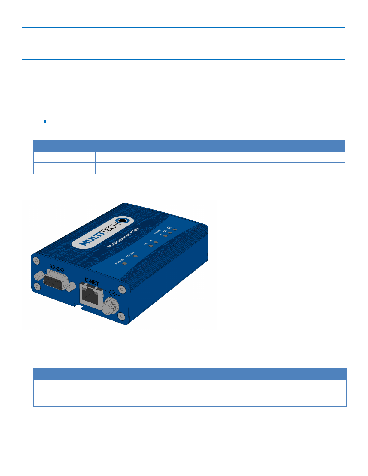
The router has an integrated cellular modem and includes 10/100 BaseT Ethernet and RS-232 serial connectivity.
An image of the device follows:
Documentation
The following documentation is available at http://www.multitech.com/brands/multiconnect-rcell-100-series.
Document Description Part Number
MultiConnect rCell100 Series
Router (MTR-LTE) User Guide
MultiConnect®rCell 100 MTR-LTE User Guide 7
This document provides overview, safety and regulatory
information, design considerations, schematics, and device
information.
S000626
Page 8

PRODUCT OVERVIEW
Document Description Part Number
API Developer Guide You can use the rCell API to manage configurations, poll
statistics, and issue commands. Documentation is available on
the MultiTech Developer Resources website at
http://www.multitech.net/developer/software/mtr-apireference/.
Getting Started with AT
Commands for LEU1 Devices
Getting Started with AT
Commands for LAT1 Devices
Getting Started with AT
Commands for LVW2 Devices
Telit LE910 AT Commands
Reference Guide
AT Command release notes and basic operations for LEU1 and
LEU1-U Devices.
AT Command release notes and basic operations for LAT1 and
LAT1-U Devices.
AT Command release notes and basic operations for LVW2 and
LVW2-U Devices.
Lists AT Commands and parameters used to configure your
device. (Applies to LAT1 and LEU1 devices, not LVW2)
Product Build Options
Product Description Carrier/Region
MTR-LAT1-B07 LTE router - cellular data only AT&T/North America
MTR-LAT1-B08 LTE router - cellular data and GPS AT&T/North America
N/A
S000615
S000617
S000618
80421ST10585A
Rev 3
MTR-LVW2-B07 LTE router - cellular data only Verizon/North America
MTR-LVW2-B08 LTE router - cellular data and GPS Verizon/North America
MTR-LEU1-B07 LTE router - cellular data only (RED compliant) Europe/Australia
MTR-LEU1-B08 LTE router - cellular data and GPS Europe/Australia
8 MultiConnect®rCell 100 MTR-LTE User Guide
Page 9
Package Contents
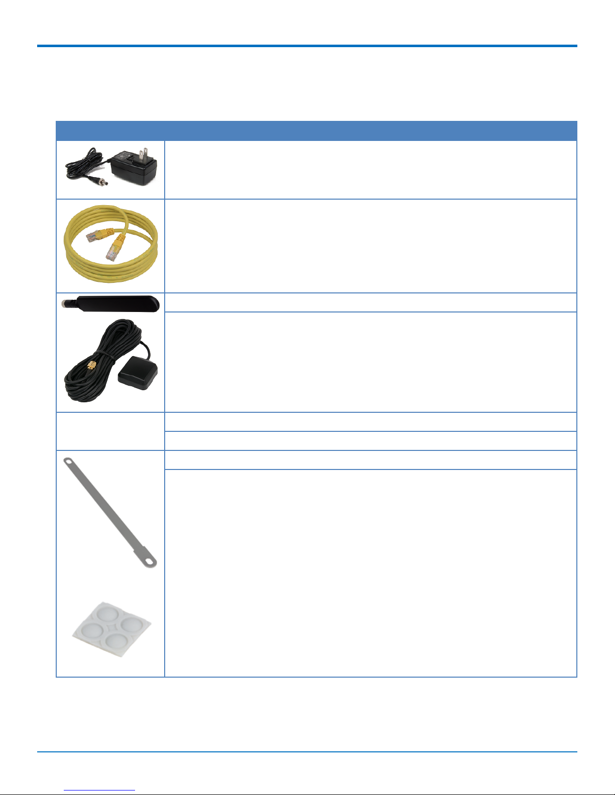
Your MTR-LTE package includes the following:
Contents Description
1 - Power Supply with Removable Blades
1 - Ethernet Cable RJ45 6-ft.
2 - Cellular Antennas
1 - GPS Antenna (B08 models only)
PRODUCT OVERVIEW
Customer Notices Legal and Support Information
Extended Services
1 - Mounting Tab and Bracket
4 - Rubber Feet
Note: The above information does not apply to the Router Only option.
MultiConnect®rCell 100 MTR-LTE User Guide 9
Page 10

PRODUCT OVERVIEW
Descriptions of LEDs
The top panel contains the following LEDs:
Power and Status LEDs—The Power LED indicates that DC power is present and the Status LED blinks when
the unit is functioning normally.
Modem LEDs—Two modem LEDs indicate carrier detection and link status.
Signal LEDs—Three signal LEDs display the signal strength level of the wireless connection.
Ethernet LEDs—These LEDs are not on the top panel. See the section Ethernet LED Descriptions for
descriptions of these LEDs.
LED Indicators
POWER Indicates presence of DC power when lit.
STATUS The LED is a solid light when the device is booting up, saving the configuration, restarting,
or updating the firmware. When the Status LED begins to blink, the router is ready for use.
CD Carrier Detect. When lit, indicates data connection has been established.
LS Link Status
(for LVW2 only, not LAT1 and LEU1)
OFF — No power to the cellular radio
Continuously Lit — Not registered
Slow Blink (-0.2Hz) — Registered or connected
SIGNAL Signal strength for cellular (RSSI range: 0 - 31)
ALL OFF — Unit is off, not registered on network, or extremely weak signal (0 <= RSSI <
6).
1 Bar “ON” — Very weak signal (7 <= RSSI <14).
1 Bar and 2 Bar “ON” — Weak signal (15 <= RSSI <23).
1 Bar, 2 Bar, and 3 Bar “ON” — Good signal (24 <= RSSI >= 31).
Ethernet LED Descriptions
Two Ethernet LEDs are physically on the RJ-45 connector(s). The table that follows describes these LEDs.
Ethernet Link Right LED on Ethernet connector. Blinks when there is transmit and receive
activity on the Ethernet link. It shows a steady light when there is a valid
Ethernet connection.
Ethernet Speed Left LED on Ethernet connector. Lit when the Ethernet is linked at 100 Mbps.
If it is not lit, the Ethernet is linked at 10 Mbps.
10 MultiConnect®rCell 100 MTR-LTE User Guide
Page 11
PRODUCT OVERVIEW
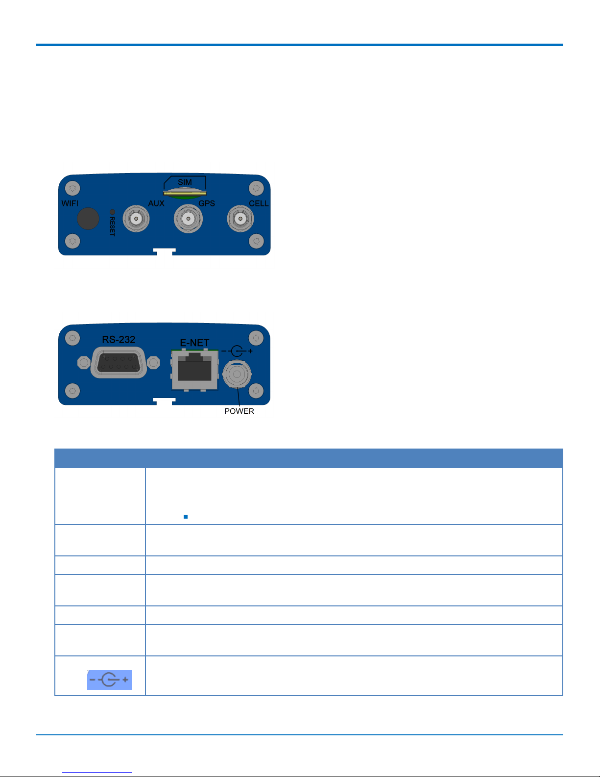
Side Panel Connectors
The device has connectors on both sides of the housing. The right side of the device contains a SIM card holder, a
reset button, a GPS antenna connector, and a cellular-auxiliary antenna connector pair. Depending on the model of
your device, the GPS antenna connector may or may not be present.
The following shows the right side panel of the device:
The following shows the left side panel of the device. It includes an RS-232 connector, an Ethernet connector, and
the power receptacle.
The following table describes the items on the two side panels:
Label Description
CELL, AUX Cellular antenna inputs. Use with the 2 Laird LTE DBA6927C1-FSMAM antennas or (for the
LEU1 only) with the 2 Wieson Technologies LTE GY115HT467-017 supplied with the device if
ordered as a bundle.
CELL - Primary. AUX - Diversity.
GPS GPS antenna input. Use with the Trimble GPS antenna 66800-52 supplied with the device
when ordered as a bundle. Used only on the B08 models.
SIM Receptacle for a SIM card (Subscriber Identity Module).
RESET Resets the device. Refer to Resetting the Device or Resetting User Defined Settings to the
Device.
RS-232 DE 9-pin, female-D Sub through-hole connector.
E-NET RJ-45 receptacle for standard Ethernet 10/100 Base-T (RJ-45 connecter has two Ethernet
LEDs).
Power 7-32 VDC power receptacle for provided power cord. The device uses a minimum 7V 1.0A
power supply.
MultiConnect®rCell 100 MTR-LTE User Guide 11
Page 12
LTE SPECIFICATIONS
Chapter 2 – LTE Specifications
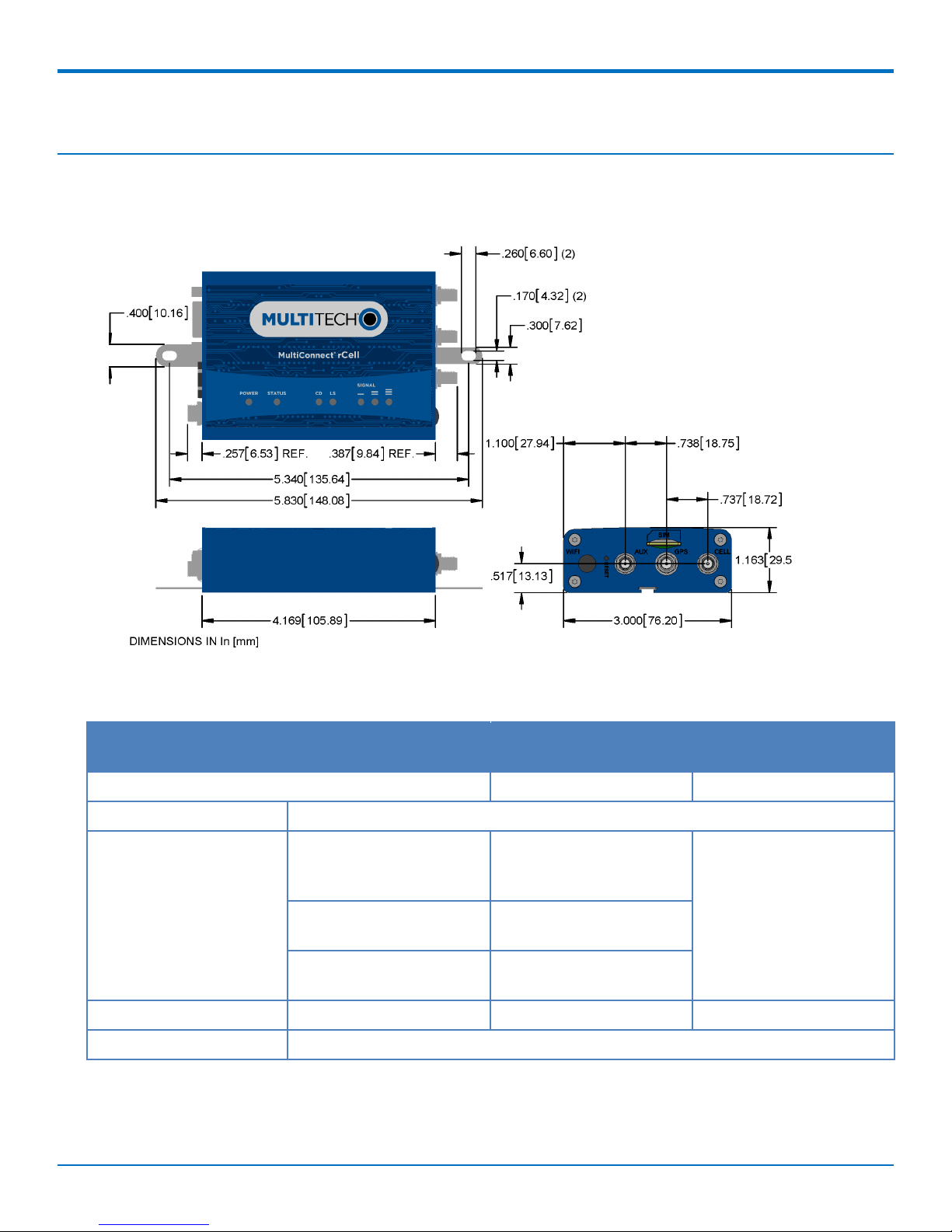
Dimensions
Specifications
Category MTR-LAT1 (North America
AT&T, T-Mobile)
General
Performance LTE Cat. 3GPP Release 9
Frequency Bands (MHz) 4G LTE: 700 (B17) / 850
(B5) / AWS1700 (B4) /1900
(B2)
3G UMTS | HSPA+:850 (B5)
/ 1900(B2)
2G: GSM | GPRS | EDGE:
850/1900
Cellular radio module Telit LE910-NAG Telit LE910-SVG Telit LE910-EUG
GPS radio module SKYTRAQ Venus638LP (for B08 models only)
MTR-LVW2 (North
America Verizon)
4G LTE: Single-mode: 700
(B13) / AWS1700 (B4)
MTR-LEU1 (EU Carriers)
See the following
Frequency Bands table for
details.
12 MultiConnect®rCell 100 MTR-LTE User Guide
Page 13

LTE SPECIFICATIONS
Category MTR-LAT1 (North America
AT&T, T-Mobile)
MTR-LVW2 (North
America Verizon)
MTR-LEU1 (EU Carriers)
Cellular packet data Up to 100 Mbps downlink (Theoretical maximum - actual performance may be
affected by multiple environmental factors.)
Up to 50 Mbps uplink (See above note.)
Diversity/MIMO Rx Diversity and MIMO DL 2x2
SMS Point-to-Point messaging, Mobile terminated SMS, Mobile originated SMS
Connectors
Cellular Female SMA connector
GPS Female SMA connector
SIM Holder Mini-SIM standard 1.8 V
and 3 V
N/A Mini-SIM standard 1.8 V
and 3 V
eNet (LAN) RJ-45, 10/100 Base T
GPS Female SMA connector
RS-232 DCE 9-pin, female connector
Power 25 mm miniature locking power jack (screw on)
Power Requirements
1
Voltage 7 V to 32 V DC
Physical Description
Dimensions 4.17” x 3.0” x 1.15” (10.6cm x 7.6cm x 2.9cm)
Weight 0.51 lbs (0.231 Kg)
Chassis type Aluminum
Environment
Operating Temperature
Storage Temperature
2
-40° C to +80° C
2
-40° C to +85° C
Humidity Relative humidity 15% to 93% non-condensing
Certifications, Compliance, Warranty
Regulatory FCC Class B (U.S.), IC
FCC Class B (U.S.) CE Mark, RED (EU)
(Canada)
Safety UL60950-1, UL 201,
UL60950-1, UL 201 IEC60950-1(EU)
cUL60950-1
Network PTCRB, AT&T, T-Mobile Verizon (pending) Telstra, EU carriers
Quality Designed and built-in ISO 9001/13485 facilities
MIL-STD-810: High Temp, Low Temp, Cold Dwell, Random, and Sine vibration
SAE J1455: Random and Sine vibration
MultiConnect®rCell 100 MTR-LTE User Guide 13
Page 14

LTE SPECIFICATIONS
1
Optional power supply must be a Listed ITE power supply marked LPS or Class 2 rated 1.0 A minimum.
Certification does not apply or extend to voltages outside certified range, and has not been evaluated by UL for
operating voltages beyond tested range.
2
UL Recognized @ 40° C, Limited by AC power supply. UL Recognized @ 60° C when used with the fused DC power
cable, part number FPC-532-DC.
Installation in outdoor locations has not been evaluated by UL. UL Certification does not apply or extend to
outdoor applications.
Note: Radio performance may be affected at the temperature extremes. This is considered normal. There is no
single cause for this function. Rather, it is the result of an interaction of several factors, such as the ambient
temperature, the operating mode, and the transmit power.
Frequency Bands (LEU1)
Mode Freq. TX (MHz) Freq. RX (MHz) Channels TX - RX offset
EGSM900 890 - 915 935 - 960 0 - 124 45 MHz
880 - 890 925 - 935 975 - 1023 45 MHz
DCS1800 1710 - 1785 1805 - 1880 512 - 885 95MHz
WCDMA850 (band V) 824 - 849 869 - 894
Tx: 4132 - 4233
45MHz
Rx: 4357 - 4458
WCDMA900 (band
VIII)
880 - 915 925 - 960
Tx: 2712 - 2863
45MHz
Rx: 2937 - 3088
WCDMA2100 (bandI)1920 - 1980 2110 - 2170
Tx: 9612 - 9888
190MHz
Rx: 10562 10838
LTE800 (band XX) 832 - 862 791 - 821
Tx: 24150 -
-41MHz
24449
Rx: 6150 - 6449
LTE1800 (band III) 1710 - 1785 1805 - 1880
Tx: 19200 -
95MHz
19949
Rx: 1200 - 1949
LTE2600 (band VII) 2500 - 2570 2620 - 2690
Tx: 20750 -
120MHz
21449
14 MultiConnect®rCell 100 MTR-LTE User Guide
Rx: 2750 - 3449
Page 15
LE910 Telit Transmission Output Power
Band Power Class
GSM 850/900 MHz 4 (2W)
DCS 1800, PCS 1900 MHz 1 (1W)
EDGE, 850/900 MHz E2 (0.5W)
EDGE, 1800/1900 MHz Class E2 (0.4W)
LTE SPECIFICATIONS
WCDMA/FDD 800/850/900, AWS 1700, 1900/2100
MHz
LTE FDD 700/800/850/900, AWS 1700,
1800/1900/2100/2600 MHz
Class 3 (0.25W)
Class 3 (0.2W)
Power Draw
MTR-LAT1-B08 Power Draw
Radio Protocol Sleep Mode
Current (If
Applicable)
(Amps)
9.0 Volts
GSM 850Mhz NA 0.185 0.329 0.900 1.53
LTE NA 0.193 0.488 NA 1.53
20.0 Volts
GSM 850Mhz NA 0.094 0.160 0.455 .721
Cellular Call Box
Connection No
Data (Amps)
Average Measured
Current (Amps) at
Maximum Power
TX Pulse (Avg)
Amplitude
Current (Amps) )
for GSM850 or
Peak Current for
HSDPA/LTE
Total Inrush
Charge
Measured in
Millicoulombs
(mC)
LTE NA 0.100 0.232 NA .721
32.0 Volts
GSM 850Mhz NA 0.062 0.103 0.370 1.91
LTE NA 0.065 0.154 NA 1.91
MTR-LEU1-B08 Power Draw
Radio Protocol Sleep Mode
Current (If
Applicable)
(Amps)
9.0 Volts
EGSM 900Mhz NA 0.185 0.305 1.05 0.118
MultiConnect®rCell 100 MTR-LTE User Guide 15
Cellular Call Box
Connection No
Data (Amps)
Average Measured
Current (Amps) at
Maximum Power
TX Pulse (Avg)
Amplitude
Current (Amps) )
for GSM850 or
Peak Current for
HSDPA/LTE
Total Inrush
Charge
Measured in
Millicoulombs
(mC)
Page 16
LTE SPECIFICATIONS
Radio Protocol Sleep Mode
Current (If
Applicable)
(Amps)
Cellular Call Box
Connection No
Data (Amps)
Average Measured
Current (Amps) at
Maximum Power
TX Pulse (Avg)
Amplitude
Current (Amps) )
for GSM850 or
Peak Current for
Total Inrush
Charge
Measured in
Millicoulombs
(mC)
HSDPA/LTE
LTE NA 0.181 0.487 0.580 0.118
20.0 Volts
EGSM 900Mhz NA 0.095 0.149 0.505 0.106
LTE NA 0.101 0.236 0.316 0.106
32.0 Volts
EGSM 900Mhz NA 0.063 0.097 0.300 0.281
LTE NA 0.069 0.153 0.228 0.281
MTR-LVW2-B08 Power Draw
Radio Protocol Sleep Mode
Current (If
Applicable)
(Amps)
Cellular Call Box
Connection No
Data (Amps)
Average Measured
Current (Amps) at
Maximum Power
TX Pulse (Avg)
Amplitude
Current (Amps) )
for GSM850 or
Peak Current for
Total Inrush
Charge
Measured in
Millicoulombs
(mC)
HSDPA/LTE
9.0 Volts
LTE NA 0.174 0.442 0.528 0.856
20.0 Volts
LTE NA 0.094 0.214 0.288 0.860
32.0 Volts
LTE NA 0.062 0.138 0.204 2.74
16 MultiConnect®rCell 100 MTR-LTE User Guide
Page 17
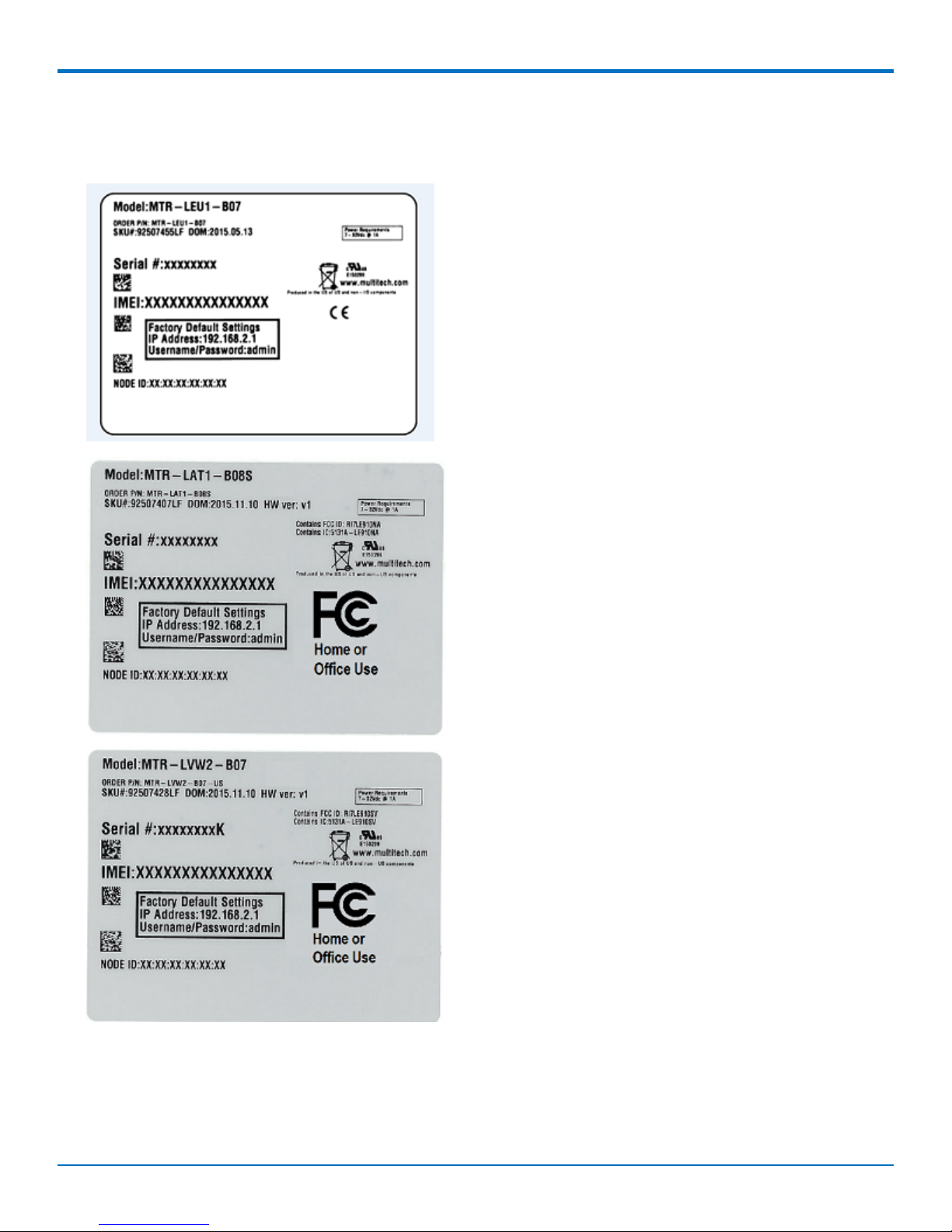
Regulatory Information Labels
The images that follow show where you can find regulatory information for your device.
LTE SPECIFICATIONS
MultiConnect®rCell 100 MTR-LTE User Guide 17
Page 18

LTE SPECIFICATIONS
RF Specifications LTE
Device Supported RF Technologies
MTR-LAT1 GSM/GPRS/Edge 850, GSM/GPRS/Edge 1900, UMTS/HSPA+ 850, UMTS/HSPA+ 1900, LTE 700,
LTE 850, LTE 1700, LTE 1900
MTR-LEU1 GSM/GPRS/Edge 900, GSM/GPRS/Edge 1800, UMTS/HSPA+ 850, UMTS/HSPA+ 900,
UMTS/HSPA+ 2100, LTE 800, LTE 1800, LTE 2600
MTR-LVW2 LTE 700, LTE 1700
18 MultiConnect®rCell 100 MTR-LTE User Guide
Page 19

Chapter 3 – Safety Warnings
Lithium Battery
A lithium battery (3V, coin cell, CR1632) located within the product provides backup power for the
timekeeping. This battery has an estimated life expectancy of ten years.
When this battery starts to weaken, the date and time may be incorrect.
Battery is not user replaceable. If the battery fails, the device must be sent back to MultiTech Systems for
battery replacement.
Lithium cells and batteries are subject to the Provisions for International Transportation. Multi-Tech
Systems, Inc. confirms that the Lithium batteries used in the MultiTech product(s) referenced in this manual
comply with Special Provision 188 of the UN Model Regulations, Special Provision A45 of the ICAO-TI/IATADGR (Air), Special Provision 310 of the IMDG Code, and Special Provision 188 of the ADR and RID (Road and
Rail Europe).
CAUTION: Risk of explosion if this battery is replaced by an incorrect type. Dispose of batteries according to
instructions.
Attention: Risque d'explosion si vous remplacez la batterie par un modèle incompatible. Jetez les piles usagées
selon les instructions.
SAFETY WARNINGS
User Responsibility
Respect all local regulations for operating your wireless device. Use the security features to block unauthorized use
and theft.
Power Supply Caution
CAUTION: Do not replace the power supply with one designed for another product; doing so can damage the
modem and void your warranty.
CAUTION: Pour garantir une protection continue contre les risques d'incendie, remplacez les fusibles
uniquement par des fusibles du même type et du même calibre.
Device Maintenance
When maintaining your device:
Do not attempt to disassemble the device. There are no user serviceable parts inside.
Do not misuse the device. Follow instructions on proper operation and only use as intended. Misuse could
make the device inoperable, damage the device and/or other equipment, or harm users.
Do not apply excessive pressure or place unnecessary weight on the device. This could result in damage to
the device or harm to users .
Do not use this device in explosive or hazardous environments unless the model is specifically approved for
such use. The device may cause sparks. Sparks in explosive areas could cause explosion or fire and may
result in property damage, severe injury, and/or death.
Do not expose your device to any extreme environment where the temperature or humidity is high. Such
exposure could result in damage to the device or fire.
Do not expose the device to water, rain, or spilled beverages. It is not waterproof. Exposure to liquids could
result in damage to the device.
MultiConnect®rCell 100 MTR-LTE User Guide 19
Page 20

SAFETY WARNINGS
Do not place the device alongside computer discs, credit or travel cards, or other magnetic media. The
information contained on discs or cards may be affected by the device.
Using accessories, such as antennas, that MultiTech has not authorized or that are not compliant with
MultiTech's accessory specifications may invalidate the warranty.
If the device is not working properly, contact MultiTech Technical Support.
Vehicle Safety
When using your device in a vehicle:
Do not use this device while driving.
Respect national regulations on the use of cellular devices in vehicles.
If incorrectly installed in a vehicle, operating the wireless device could interfere with the vehicle’s
electronics. To avoid such problems, use qualified personnel to install the device. The installer should verify
the vehicle electronics are protected from interference.
Using an alert device to operate a vehicle’s lights or horn is not permitted on public roads.
UL evaluated this device for use in ordinary locations only. UL did NOT evaluate this device for installation in
a vehicle or other outdoor locations. UL Certification does not apply or extend to use in vehicles or outdoor
applications.
Radio Frequency (RF) Safety
Due to the possibility of radio frequency (RF) interference, it is important that you follow any special regulations
regarding the use of radio equipment. Follow the safety advice given below.
Operating your device close to other electronic equipment may cause interference if the equipment is
inadequately protected. Observe any warning signs and manufacturers’ recommendations.
Different industries and businesses restrict the use of cellular devices. Respect restrictions on the use of
radio equipment in fuel depots, chemical plants, or where blasting operations are in process. Follow
restrictions for any environment where you operate the device.
Do not place the antenna outdoors.
Switch OFF your wireless device when in an aircraft. Using portable electronic devices in an aircraft may
endanger aircraft operation, disrupt the cellular network, and is illegal. Failing to observe this restriction
may lead to suspension or denial of cellular services to the offender, legal action, or both.
Switch OFF your wireless device when around gasoline or diesel-fuel pumps and before filling your vehicle
with fuel.
Switch OFF your wireless device in hospitals and any other place where medical equipment may be in use.
Interference with Pacemakers and Other Medical Devices
Potential interference
Radio frequency energy (RF) from cellular devices can interact with some electronic devices. This is
electromagnetic interference (EMI). The FDA helped develop a detailed test method to measure EMI of implanted
cardiac pacemakers and defibrillators from cellular devices. This test method is part of the Association for the
Advancement of Medical Instrumentation (AAMI) standard. This standard allows manufacturers to ensure that
cardiac pacemakers and defibrillators are safe from cellular device EMI.
20 MultiConnect®rCell 100 MTR-LTE User Guide
Page 21

SAFETY WARNINGS
The FDA continues to monitor cellular devices for interactions with other medical devices. If harmful interference
occurs, the FDA will assess the interference and work to resolve the problem.
Precautions for pacemaker wearers
If EMI occurs, it could affect a pacemaker in one of three ways:
Stop the pacemaker from delivering the stimulating pulses that regulate the heart's rhythm.
Cause the pacemaker to deliver the pulses irregularly.
Cause the pacemaker to ignore the heart's own rhythm and deliver pulses at a fixed rate.
Based on current research, cellular devices do not pose a significant health problem for most pacemaker wearers.
However, people with pacemakers may want to take simple precautions to be sure that their device doesn't cause
a problem.
Keep the device on the opposite side of the body from the pacemaker to add extra distance between the
pacemaker and the device.
Avoid placing a turned-on device next to the pacemaker (for example, don’t carry the device in a shirt or
jacket pocket directly over the pacemaker).
Notice regarding Compliance with FCC, EU, and Industry Canada
Requirements for RF Exposure
The antenna intended for use with this unit meets the requirements for mobile operating configurations and for
fixed mounted operations, as defined in 2.1091 of the FCC rules for satisfying RF exposure compliance. This device
also meets the European RF exposure requirements of EN 62311. If an alternate antenna is used, consult user
documentation for required antenna specifications.
Compliance of the device with the FCC, EU and IC rules regarding RF Exposure was established and is given with
the maximum antenna gain as specified above for a minimum distance of 20 cm between the devices radiating
structures (the antenna) and the body of users. Qualification for distances closer than 20 cm (portable operation)
would require re-certification.
Wireless devices could generate radiation. Other nearby electronic devices, like microwave ovens, may also
generate additional radiation to the user causing a higher level of RF exposure.
MultiConnect®rCell 100 MTR-LTE User Guide 21
Page 22
ANTENNA INFORMATION
Chapter 4 – Antenna Information
Antenna System Cellular Devices
The cellular/wireless performance depends on the implementation and antenna design. The integration of the
antenna system into the product is a critical part of the design process; therefore, it is essential to consider it early
so the performance is not compromised. If changes are made to the device's certified antenna system, then
recertification will be required by specific network carriers.
The antenna system is defined as the UFL connection point from the gateway to the specified cable specifications
and specified antenna specifications.
Laird Antenna Used with -LAT1 and -LVW2 Models
The cellular radio portion of the device is approved with the following antenna or for alternate antennas meeting
the given specifications.
Manufacturer: Laird Technologies
Description: Dipole Blade Antenna for LTE
Model Number: DBA6927C1-FSMAM
MultiTech Part Number: 95218149LF
MultiTech ordering information:
Model Quantity
ANLTE1-2HRA 2
ANLTE1-10HRA 10
ANLTE1-50HRA 50
LTE Antenna Specifications
Category Description
Frequency Range 698-806 MHz
824-894 MHz
880-960 MHz
1710-1880 MHz
1850-1990 MHz
1920-2170 MHz
2100-2500 MHz
2500-2690 MHz
Impedance 50 Ohms
VSWR < 2.5:1
22 MultiConnect®rCell 100 MTR-LTE User Guide
Page 23
ANTENNA INFORMATION
Category Description
Typical Radiated Gain Low band 0.5 dBi (698-960 MHz)
High band 2.2 dBi (1710-2700 MHz)
Radiation Omni-directional
Polarization Linear
LTE Antenna Used with -LEU1 Models
The cellular radio portion of the device is approved with the following antenna or for alternate antennas meeting
the given specifications.
Manufacturer: Wieson Technologies
Description: LTE Antenna
Model Number: GY115HT467-017
MultiTech Part Number: 95218146LF
MultiTech ordering information:
Model Quantity
ANLTE2-2HRA 2
ANLTE2-10HRA 10
ANLTE2-50HRA 50
LTE Antenna Specifications
Category Description
Frequency Range 690-960 MHz
1710-2170 MHz
2300-2690 MHz
Impedance 50 Ohms
VSWR 3:1
Peak Radiated Gain 3.5 dBi
Radiation Omni-directional
Polarization Linear
GPS Antenna Specifications
Manufacturer: Trimble
Description: GPS Antenna with low noise amplifier
Model Number: 66800-52
MultiConnect®rCell 100 MTR-LTE User Guide 23
Page 24
ANTENNA INFORMATION
Multi-Tech Part Number: 45009665L
MultiTech Ordering Information
Model Quantity
ANGPS-1MM 1
ANGPS-10MM 10
ANGPS-50MM 50
Antenna Specifications
Category Description
Frequency Range 1575.24 MHz
Impedance 50 Ohms
VSWR 2.0:1 max
Gain 10-30 dBi
LNA Current Consumption 40 mA max
Noise Figure < 2dB
Polarization RHCP
Input voltage 3.0V M M 0.2V
24 MultiConnect®rCell 100 MTR-LTE User Guide
Page 25

Chapter 5 – Installing the Router
Installing the Router
1. To use the router’s cellular features, connect two suitable antennas to both the CELL and AUX
connectors.
2. You must use diversity because this device requires two antennas.
3. Using an Ethernet cable, connect one end of the cable to the E-NET connector on the back of the router
and the other end to your computer, either directly or through a switch or hub.
4. If you are connecting to a serial interface, connect the DE-9 connector (9-pin) of the RS-232 cable to the
RS-232 connector on the router. Then connect the other end to the serial port on the desired device.
5. Some routers support the use of a GPS receiver. If you are using a GPS receiver with the router, attach
the GPS cable to the GPS connector on the router.
6. Attach a power cable to your power supply module.
7. Screw-on the power lead from the power supply module into the power connection on the router.
8. Plug the power supply into your power source.
The POWER LED lights after the device powers up.
When the Status LED begins to blink, the device is ready for use.
9. You can configure your router by using your router’s web management interface. You might need to
change the IP address of your computer to be in the same IP and subnet mask range as the device.
INSTALLING THE ROUTER
a. Open a web browser. In the browser's address field, type the default address for the router:
http://192.168.2.1. (If the browser displays a message that there is a problem with the website's
security certificate, ignore this and click Continue to the webpage).
b. A login page opens. In the username field, type the default user name: admin (all lower-case).
c. In the password field, type the default password: admin (all lower-case).
d. Click Login. The Web Management Home page opens. Online documentation included with the web
management interface describes how to configure your router.
Mounting the Device
1. Locate the groove on the bottom of the modem.
2. Slide the mounting rod through the groove.
3. To secure the rod to the desired surface, place and tighten two screws in the holes on either end of the
mounting rod. The dimensions illustration in this guide shows the mounting rod, as well as the
dimensions for placement of the screws.
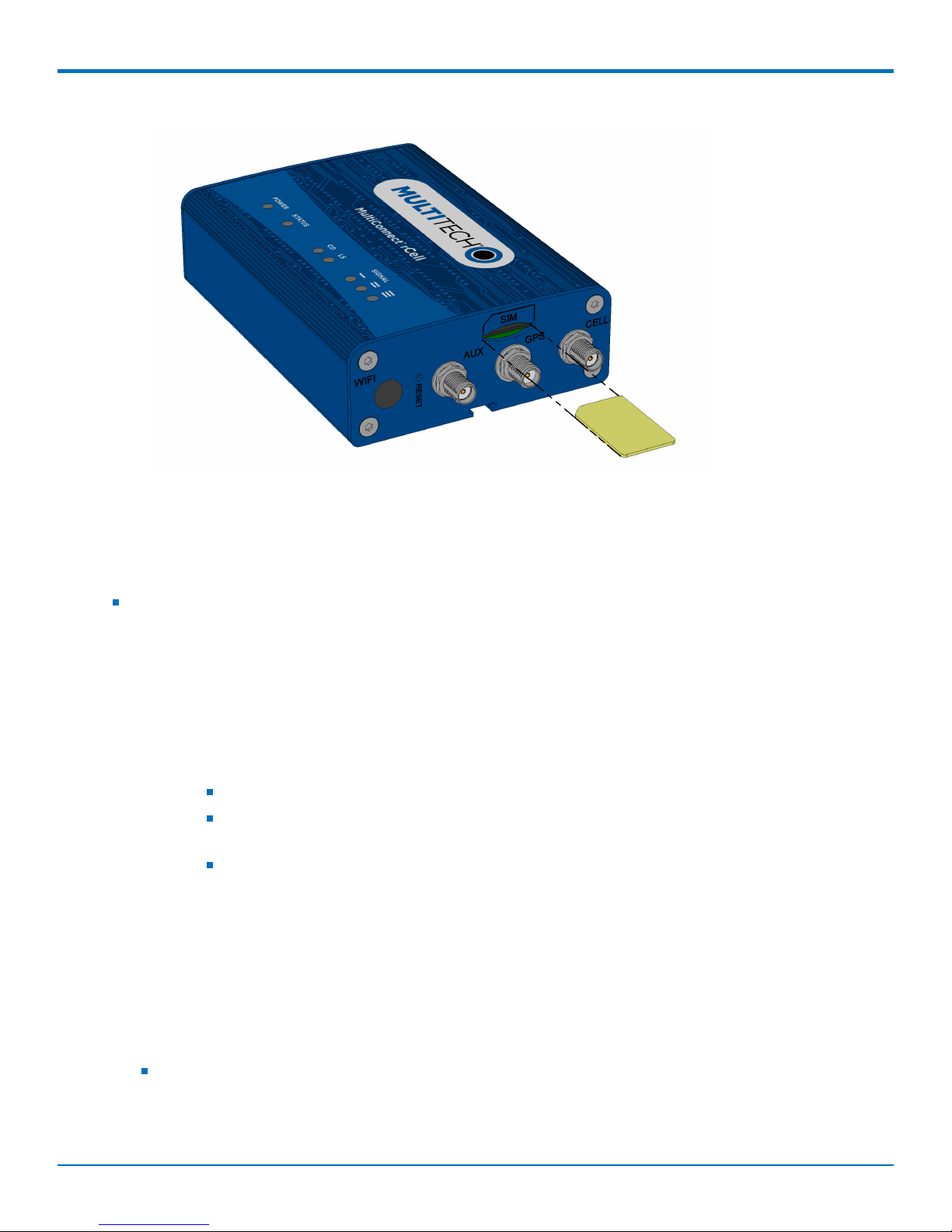
Installing the SIM Card
If you want to operate the router on a particular network, install a SIM card (Subscriber Identity Module).
To install the SIM:
1. Locate the SIM card slot on the side of the router. The slot is labeled SIM.
MultiConnect®rCell 100 MTR-LTE User Guide 25
Page 26
INSTALLING THE ROUTER
2. Push the SIM card into the slot until it snaps into place.
3. To remove the SIM, push the edge of the card in. When released, the card pops out of the device.
Resetting the Device
You need:
A pin, paperclip, or similar thin object that can fit into the reset hole
The following is the default condition for the RESET button on the device. You can program a change to the
behavior of the button if needed.
To reset the device:
1. Find the hole labeled RESET. The reset button is recessed into the case.
2. Use the pin to press and release the RESET button as follows:
Reset options:
To reboot, press RESET for less than 3 seconds.
To reboot and restore user-defined defaults (if previously set), press RESET for 3 to 29
seconds.
To reboot, restore factory settings, and erase user-defined defaults, press RESET for 30
seconds or longer.
Note: The device reboots when restoring settings.
Restoring User Defined Settings to the Device
You can restore user defined settings to your device.
You need:
A pin, paperclip, or similar thin object that can fit into the reset hole
1. Locate the hole in the panel labeled RESET. The reset button is recessed into the housing.
2. Use the pin to press in the button for about 3 seconds and then release the reset button.
26 MultiConnect®rCell 100 MTR-LTE User Guide
Page 27

INSTALLING THE ROUTER
a. If you do not press in the button long enough, the device will reset, but the user defined settings will
not be restored.
b. If you hold it too long, factory default settings will be restored.
MultiConnect®rCell 100 MTR-LTE User Guide 27
Page 28

USING THE WIZARD TO CONFIGURE YOUR DEVICE
Chapter 6 – Using the Wizard to Configure Your
Device
First-Time Setup
If you need to change the mode of your device, this is the only way to do so. This section is not available through
the device management software.
Other than when you first power up the device, you must configure the device to factory default settings, reset it
and then, access it through the default 192.168.2.1 IP address to see the first-time setup. This wizard helps you
configure the main features of your rCell.
Depending on the mode, your proceeding options and fields differ (see the description for each step for details
below). Here are the steps for first-time setup:
1. On the first page, the mode option lets you set up the rCell as a Network Router, PPP-IP Passthrough, or
Serial Modem device. If you switch modes, we recommend that you reset the device and configure to
factory default settings.
a. The Network Router mode is the default and establishes the device as a cellular network router.
b. In the PPP-IP Passthrough mode, the rCell assigns the IP address it receives from the cellular
provider to the Ethernet-attached device. In this mode, the rCell only allows one DHCP lease.
Note: In this mode, many of the rCell services described in this document are non-configurable and
do not appear in the device configuration menu. All IP traffic is passed between the Ethernetattached device and the cellular provider with no firewall functionality.
c. The Serial Modem mode creates a serial connection to the device which can be configured for speed
and flow control. The serial port talks to the cellular radio in order to send and receive messages via
the cellular radio.
d. Click Next.
2. In the Choose Password page, enter the following:
a. In the Current Password field, type the current password. The default password is admin.
b. In the New Password field, type the password you want to use to replace the current one.
c. To confirm the accuracy of the password, re-type it in the Confirm Password field.
d. Click Next. Or if you are done making changes, click Finish.
Note: If you do not want to change your password, click Skip.
3. In the Time Configuration page, set the date, time, and time zone.
a. In the Date field, type in the date you desire, or select the date from the pop-up calendar that
opens.
b. In the Time field, type the desired time.
c. From the Time Zone drop-down list, select the time zone in which the router operates.
d. Click Next. Or if you are done making changes, click Finish.
4. In the IP Setup page, give the router its address and network information (the fields shown vary based on
the selected mode):
28 MultiConnect®rCell 100 MTR-LTE User Guide
Page 29

USING THE WIZARD TO CONFIGURE YOUR DEVICE
If you select PPP-IP Passthrough mode, the following options are displayed:
a. In the Protocol Support field, choose the internet protocol from the drop down menu (select from
IPv4 and IPv6).
b. In the IPv4/IPv6 Address field, type the router's IP address.
c. For IPv6, in the Prefix Length field, the length of the prefix displays. Users cannot change this field.
For IPv4, in the Mask field, type the mask for the network. The default is 255.255.255.0.
d. In the IPv6/IPv4 Primary DNS field, type the address of the primary DNS (optional).
Note: This is an optional value that can be used if you use a DNS server other than the servers
received from your carrier.
e. Click Next. Or if you are done making changes, click Finish.
If you select Network Router or Serial Modem mode, the following options are displayed:
a. In the IP Address field, type the router's IP address.
b. In the Mask field, type the mask for the network. The default is 255.255.255.0.
c. This field is only available in Network Router mode. If you select Serial Modem mode, skip this step.
In the IPv4 Primary DNS field, type the address of the primary DNS (optional).
Note: This is an optional value that can be used if you use a DNS server other than the servers
received from your carrier.
d. Click Next. Or if you are done making changes, click Finish.
5. This section is only available if you select Network Router or PPP-IP Passthrough mode. If you select
Serial Modem mode, skip this step. In the PPP Configuration page, configure PPP for your router.
a. To use PPP, check Enabled. When enabled, your device functions as a router.
b. For devices that use two antennas, Diversity is enabled by default. Diversity enables the use of two
cellular antennas for better performance. ( See Installing the Router for more details).
c. To enable the dial-on-demand feature, check Dial-on-Demand. This indicates to the router to bring
up the PPP connection when there is outgoing IP traffic, and take down the PPP connection after a
given idle timeout.
d. In the APN field, type the APN (Access Point Name). The APN is assigned by your wireless service
provider.
e. Click Next. Or if you are done making changes, click Finish.
6. This section is only available if you select Network Router or PPP-IP Passthrough mode. If you select
Serial Modem mode, skip this step. In the PPP Authentication page:
a. From Type, select the authentication protocol type used to negotiate with the remote peer: PAP,
CHAP, or PAP-CHAP. The default value is NONE.
b. In the Username field, type the username with which the remote peer authenticates. You can leave
this field blank, if desired. Username is limited to 60 characters.
c. In the Password field, type the password with which the remote peer authenticates. You can leave
this field blank, if desired. Password is limited to 60 characters.
7. This section is only available if you select Serial Modem mode. For any other mode, skip this step. In the
Serial Port Configuration page:
MultiConnect®rCell 100 MTR-LTE User Guide 29
Page 30

USING THE WIZARD TO CONFIGURE YOUR DEVICE
a. From Baud Rate, select baud rate in BPS for the serial port from the drop down list. Default setting is
115200.
b. In the Flow Control field, select the flow control option from the drop down list provided. Choose
from NONE or RTS-CTS.
c. In the Parity field, select the parity option from the drop down list. Choose from NONE, ODD, or
EVEN.
d. In the Data Bits field, select the data bits option from the drop down list. Choose from 7 or 8.
e. In the Stop Bits field, select the stop bit option from the drop down list. Choose from 1 or 2.
8. Click Finish.
9. To save your settings, click Save and Restart.
30 MultiConnect®rCell 100 MTR-LTE User Guide
Page 31

CONFIGURING YOUR DEVICE
Chapter 7 – Configuring Your Device
Home Page (Dashboard)
The Home page (dashboard) displays a summary of the configuration settings for the MultiConnect rCell device.
The following settings, where applicable, include the area of the Web Management interface where they can be
accessed and changed.
Click Home to display the following information:
Router:
Model Number: The MultiConnect rCell model ID.
Serial Number: The MultiTech device ID.
IMEI: International Mobile Station Equipment Identity.
Firmware: MultiConnect rCell MTR firmware version.
Current Time: Current date and time of the router. For information on setting the date and time, go to
Setup > Time Configuration.
Up Time: Amount of time the device has been continuously operating.
WAN Transport: Current transport for IP traffic leaving the LAN.
LAN:
MAC Address: Media Access Control Address used to uniquely identify the devices LAN Ethernet
interface.
IP Address: LAN IP address of this device. To configure the IP address, go to Setup > IP Configuration.
Netmask: Network mask of the LAN. To configure the network mask, go to Setup > IP Configuration.
Gateway: Default gateway IP address of the LAN. To configure the default gateway, go to Setup > IP
Configuration.
DNS: Current Domain Name System IP addresses known by this device. To configure the DNS, go to
Setup > IP Configuration.
DHCP State: Current state of this device's DHCP server. To configure, go to Setup > DHCP Configuration.
Lease Range: Current DHCP lease range of this device's DHCP server. To configure, go to Setup > DHCP
Configuration.
Cellular:
Protocol Support (only available when you choose PPP-IP Passthrough): Choose from IPv4 or IPv6. If you
choose IPv6, also enter the Connect Timeout.
State: Current state of the cellular PPP link. For more information, go to Cellular > Cellular
Configuration.
Signal: Current signal strength of the cellular link. Mouse hover provides dBm value.
Connected: Total time connected for the current PPP session.
IP Address: Current cellular WAN IP address issued to this device by the cellular carrier.
Roaming: Indicates whether or not this device's cellular link is currently connected to its home network.
Phone number: Device's cellular phone number also known as Mobile Directory Number (MDN). This
field is blank if the MDN is not stored in the SIM card.
Tower: Tower ID of the cellular tower currently providing cellular service to this device.
MultiConnect®rCell 100 MTR-LTE User Guide 31
Page 32

CONFIGURING YOUR DEVICE
WAN Setup
Configuring WAN Failover Priority
Failover mode regulates which WAN is used for the Internet connection and switches the WAN if a connectivity
failure is detected.
Failover mode enables the WAN with the highest priority as displayed on the WAN Configuration page. If the WAN
with priority 1 is disabled or a connection failure is detected, the WAN with priority 2 is automatically selected for
establishing connection to the Internet.
If Ethernet is used as WAN, the DHCP server must be disabled.
1. Click Setup > WAN Configuration.
2. Under Options, click the up and down arrows to change the priority of the appropriate WAN.
3. Click Save and Restart to save the change.
For field descriptions see Failover Configuration Fields
For information on editing WAN Failover see Editing Failover Configuration
Editing Failover Configuration
The device can use the active or passive mode to monitor the Internet availability in WAN. The default condition is
active mode.
Active mode can be type ICMP (ping) or TCP. ICMP periodically pings the designated host at the specified interval.
TCP tries to make a connection to the designated host at the interval specified.
For both ICMP and TCP, if a response is not received, the device switches to the WAN with lower priority. The
device continues to ping the designated host at the interval specified for WAN with the higher priority and
switches back when the ping is successful. When passive mode is enabled, the device switches the WANs when the
network interface is down. The currently active WAN is displayed on the home page under the label WAN
Transport.
To edit failover configuration:
1. Click Setup > WAN Configuration.
2. Under the Options column at the right, click the pencil icon (edit) for the selected WAN. The Failover
Configuration page is displayed.
3. Make the desired changes. Refer to Failover Configuration Fields for details.
4. Click Finish.
5. If you are finished making changes, click Save and Restart.
Failover Configuration Fields
Field Description
Monitoring Mode Use the drop-down list to select the mode to connect to the host: PASSIVE or
ACTIVE.
Interval Enter the number of seconds between each check. Default is 60 seconds.
Host Name Enter the host name or IP address to use for the check. Default is www.google.com.
32 MultiConnect®rCell 100 MTR-LTE User Guide
Page 33

CONFIGURING YOUR DEVICE
Field Description
Mode Type Use the drop-down list to select the mode type: ICMP or TCP. Default is ICMP.
(Active Monitoring Mode)
TCP Port Enter the TCP Port number to connect to the host. (Mode TCP)
ICMP Port Enter the number of ICMP pings to be sent to the specified host. Default is 10.
(Mode ICMP)
Unavailable Services in PPP-IP Passthrough and Serial Modem
Modes
In both PPP-IP Passthrough and Serial Modem modes, many rCell services described in this document are nonconfigurable and therefore do not appear in the device configuration menu. If you choose one of these modes, all
sections between this and the next note on this subject are not available.
Configuring IP Address and DNS Information for LAN
Your router manages traffic for your local area network (LAN). To change the IP address and DNS configuration:
1. From Setup, select IP Configuration.
2. To configure the address LAN information:
In the IP Address field, type the router's IP address. The default is 192.168.2.1.
In the Mask field, type the mask for the network. The default is 255.255.255.0.
In the Gateway field, type the IP address of the network's gateway (router). If this device is the gateway,
leave this field blank.
3. To resolve domain names, configure domain name server information (DNS).
To allow the router to behave as a local DNS forwarder, check Enable Forwarding Server.
Note: When a DNS request is received, the router forwards the request to a remote DNS server if
there is no record in the router’s cache. New requests are cached in the router for future
requests.
In the Primary Server field, type the address of the primary DNS.
In the Secondary Server field, type the address of the secondary DNS.
The WAN DNS Servers field displays information about DNS servers, if any, that have been detected on
the WAN link of the router.
4. Click Submit.
5. To save your changes, click Save and Restart.
Configuring Dynamic Domain Naming System (DDNS)
This feature allows your router to use a DDNS service to associate a hosted server's domain name with a
dynamically changing internet address. To configure your router to use DDNS:
1. From Setup, select DDNS Configuration.
2. In the Configuration group, check Enabled.
3. In the Service drop-down list, select a DDNS service. To define a service that isn't listed choose Custom.
a. For custom DDNS service, in the Service field, type the DDNS server's URL.
MultiConnect®rCell 100 MTR-LTE User Guide 33
Page 34

CONFIGURING YOUR DEVICE
b. For custom DDNS service, in the Port field, type the DDNS server's port.
4. In the Domain field, type the registered Domain name.
5. In the Update Interval field, type the days that can pass with no IP Address change. At the end of this
interval, the existing IP Address is updated on the server so that the address does not expire. The range
of the interval you can enter is between 1 and 99 days. The default is 28 days.
6. Check Use Check IP, if you want to query the server to determine the IP address before the DDNS update.
The IP address is still assigned by the wireless provider and the DDNS is updated based on the address
returned by Check IP Server. If disabled, the DDNS update uses the IP address from the PPP link. The
default is Use Check IP.
7. In the Check IP Server field, type the name to which the IP Address change is registered. Example:
checkip.dyndns.org
8. In the Check IP Port field, type the port number of the Check IP Server. The default is 80.
9. From the System drop-down list, select the desired system registration type, either Dynamic or Custom.
The default is Dynamic.
10. Enter Username of the server.
11. Enter Password of the server.
12. To force update of DDNS, click Update.
13. Click Submit.
14. To save your changes, click Save and Restart.
Entering authentication information
Your DDNS server requires you to identify yourself before you can make changes.
1. In the Username field, type the name that can access the DDNS Server. The default is NULL. You receive
your name when you register with the DDNS service.
2. In the Password field, type the password that can access the DDNS Server. The default is NULL. You
receive your password when you register with the DDNS service.
3. Click Submit. If you are finished making changes click Save and Restart.
Forcing a DDNS server update
To update the DDNS server with your IP address, click Update.
Configuring Dynamic Host Configuration Protocol (DHCP) Server
You can configure your device to function as a DHCP server that supplies network configuration information, such
as IP address, subnet mask, and broadcast address, to devices on the network. To configure the DHCP server:
1. From Setup, select DHCP Configuration.
2. To use the DHCP feature, check Enabled.
3. The Subnet field displays the subnet address.
4. The Mask field displays the network's subnet mask.
5. In the Gateway field, type the gateway address. The default Gateway address is the LAN IP address of the
device.
6. In the Domain field, type your network domain, if any.
7. In the Lease Range Start field and in the Lease Range End field, type the range of IP addresses to be
assigned by DHCP.
34 MultiConnect®rCell 100 MTR-LTE User Guide
Page 35

CONFIGURING YOUR DEVICE
8. In the Lease Time field, type the DHCP lease time. Lease time is set in days, hours, and minutes.
9. Click Submit. If you are finished making changes, click Save and Restart.
Assigning Fixed Addresses
To add fixed addresses for the DCHP server:
1. In the Fixed Address group, click Add. A dialog box opens, where you define the address.
2. In the MAC Address field, type the MAC address to which the specified IP address binds.
3. In the IP Address field, type the fixed IP address to be assigned.
4. Click Finish.
5. To save your changes, click Save and Restart.
Configuring the Global Positioning System (GPS)
This GPS information applies only to the MTR models that support GPS including:
Model B08
Some routers have a built-in GPS receiver. If your router has a GPS receiver, the router can forward NMEA
(National Marine Electronics Association) sentences from the GPS receiver to a device connected to the router's
serial port. You can also send the GPS data over the network to a remote computer.
There are four areas of GPS configuration including: Server Configuration, Local Configuration, Client
Configuration and NMEA Configuration along with Current Position information.
Notes:
All enabled sentences are forwarded periodically using the interval specified in the NMEA Configuration
section. Before forwarding, the router adds an ID prefix and ID to each enabled NMEA sentence. If set, the
NMEA sentences available are those provided by the built-in receiver which are: GPGGA, GPGSA, GPGSV,
GPGLL, GPRMC, GPVTG.
You can simultaneously enable the TCP Server, TCP/UDP client, and serial port dump.
Dumping NMEA Sentence Information to the Router's TCP Server Port
To configure the TCP server port where you can send the NMEA sentences:
1. Complete the steps under GPS Server Configuration.
2. To use the serial port for GPS, you must disable the serial port client/server. Go to Setup > Serial IP
Configuration > Serial Port Settings and uncheck Enabled.
3. Then, under Local Configuration, check Serial Port Dump.
4. Submit.
5. To save your changes, click Save and Restart.
GPS Server Configuration
To setup the GPS Server Configuration:
1. Go to Setup > GPS Configuration > Server Configuration.
2. To enable server configuration, check TCP Server.
MultiConnect®rCell 100 MTR-LTE User Guide 35
Page 36

CONFIGURING YOUR DEVICE
3. In the Port field, type the port number on which the TCP server is listening for connections. The default is
5445. You can use up to five digits. Each digit itself must be between 0 and 9. Numbers above 65,535 are
illegal as the port identification fields are 16 bits long in the TCP header.
4. Enter Password and confirm Password.
5. Click Submit.
6. To save your changes, click Save and Restart.
Sending GPS information to a remote server
The Client Configuration allows the device to connect to a remote server using the IP and port information for
uploading GPS data.
1. To allow the device to connect, go to Setup > GPS Configuration > Client Configuration.
2. Check TCP/UDP Client.
3. From the Protocol drop-down list, select the protocol of the client (TCP or UDP).
4. In the Remote Host field, type the IP address of the remote host.
5. In the Port, field type the port number of the remote host.
6. If your remote host requests a password, type that password in the Password field. The password is sent
to the server in response.
7. Click Submit.
8. To save your changes, click Save and Restart.
Configuring NMEA Sentences
To configure the time interval, additional prefix or ID information, and which NMEA sentences that can be sent:
1. Go to Setup > GPS Configuration > NMEA Configuration and in the Interval field, type the amount of
time, in seconds, that passes before the NMEA information is sent. The default is 10 seconds. The range is
1 to 255 seconds.
2. You can further identify the router, also called a remote asset, that is collecting and sending the GPS
information. To do so:
Add ID: The ID is an unique remote asset identification string. The ID string can be any length up to 20
characters. The & and $ are invalid characters. The ID must follow the standard NMEA sentence structure.
Refer to the Universal IP AT Commands Reference Guide for sentence structure.
To add more information to the beginning of the ID, in the Add ID Prefix field, type the information.
3. You can select which NMEA sentence types you want to send. Check any combination of the available
options: GGA, GSA, GSV, GLL, RMC, and VTG.
SMTP Settings
The following table lists the configuration fields in the SMTP window.
Field Description
SMTP Configuration
Enabled Click to use the SMTP feature.
Server Enter the SMTP server address.
Port Enter the port number that the SMTP server uses.
36 MultiConnect®rCell 100 MTR-LTE User Guide
Page 37

CONFIGURING YOUR DEVICE
Field Description
Email Enter the sender email address. This address will be added as the
sender email address to the sent emails.
Username Enter the name that can access the SMTP server.
Password Enter the password that can access the SMTP server.
Mail Log Settings
Entries to Keep Enter the desired number of mail log entries that are to be stored
in the router. The range of values is 10 to 1000. If you click Submit,
this setting is not applied to the emails that are in progress or
deferred. Note that logs are not saved on the device. Also, logs do
not persist through power cycles.
Send a Test Email
Address To make sure that the SMTP is configured properly, enter a
destination email address, then click Send Test Email.
Configuring the Serial Port
To configure the serial terminal connected to the RS-232 connector on the router:
1. Go to Setup > Serial IP Configuration > Serial Port Settings, check Enabled.
2. From the Baud Rate drop-down list, select the baud-rate at which the serial terminal communicates. The
default is 115200.
3. From the Flow Control drop-down list, select the flow control for the serial port. The options are NONE or
RTS-CTS. The default is NONE.
4. From the Parity drop-down list, select the parity for the serial port. The options are NONE, EVEN, or ODD.
The default is NONE.
5. To use the Modbus protocol as the protocol the serial devices use to communicate, check Modbus
Gateway.
6. From the Data Bits drop-down list, select the data bits for the serial port. Data bit options are 7 or 8. The
default is 8.
7. From the Stop Bits drop-down list, select the stop bits for the serial port. The options are 1 or 2. The
default is 1.
8. Click Submit.
9. To save your changes, click Save and Restart.
Configuring Device to Act as Client
You can set up the router to act as a client.
The TCP, UDP, SSL/TLS client feature enables the router to act as a proxy TCP, UDP, or SSL/TLS client to the serial
terminal connected to the RS-232 port on the router. This helps the serial terminal access any TCP, UDP, or SSL/TLS
server on the LAN/WAN allowing two-way traffic between the serial device and the remote server.
To use this function, you must first check Enabled under Serial Port Settings. To configure the IP Pipe in TCP, UDP,
or SSL/TLS client mode:
1. Go to Setup > Serial-IP Configuration > Serial Port Settings > IP Pipe group.
MultiConnect®rCell 100 MTR-LTE User Guide 37
Page 38

CONFIGURING YOUR DEVICE
2. From the Mode drop-down list, select CLIENT.
3. From the Protocol drop-down list, select the desired protocol: TCP, UDP, or SSL/TLS.
4. In the Server IP Address field, enter the address of the far-end TCP, UDP, or SSL/TLS server.
5. In the Server Port field, enter the port value used by the far-end TCP, UDP, or SSL/TLS server.
6. If the primary server is unavailable, in the Secondary IP Address field, enter the address of the alternate
TCP, UDP, or SSL/TLS server.
7. If the primary server is unavailable, in the Secondary Port field, enter port number value of the alternate
TCP, UDP, or SSL/TLS server.
8. From the Connection Activation drop-down list, select a connection method. Options are:
ALWAYS-ON. If you select this option, you cannot change the Connection Termination option.
DTR-ASSERT. When the DTR signal is asserted, the connection is established.
CR. Three carriage returns must be received before the TCP, UDP, or SSL/TLS connection is established to
the remote server.
ON-DEMAND. Set the connection as available on-demand.
9. From the Connection Termination drop-down list, select a disconnect method for the IP pipe. Options
are:
ALWAYS-ON.
TIMEOUT. The IP pipe connection disconnects if the configured timer expires with no data sent or
received. In the Timeout field, enter the desired number of seconds for this timeout.
SEQUENCE. A sequence of received characters disconnects the IP pipe.
DTR-TOGGLE. When the DTR control signal is toggled, the IP pipe disconnects.
10. Click Submit.
11. To save your changes, click Save and Restart.
Configuring Device to Act as Server
You can set up the router to act as a server.
The TCP, UDP, SSL/TLS server feature enables a TCP, UDP, SSL/TLS client on the Ethernet network to connect to the
remote serial terminal that is connected to the RS-232 port on the router. The router acts as a TCP, UDP, SSL/TLS
server which allows two-way traffic between the TCP, UDP, SSL/TLS client and the remote terminal on the serial
port.
To use this function, you must first check Enabled under Serial Port Settings. To configure the IP Pipe in TCP, UDP,
SSL/TLS server mode:
1. Go to Setup > Serial-IP Configuration > Serial Port Settings > IP Pipe group.
2. In the Mode drop-down list, select SERVER.
3. From the Protocol drop-down list, select the desired protocol: TCP, UDP, or SSL/TLS.
4. In the Server Port field, type the desired port value in the range 1 to 65535.
5. From the Connection Termination drop-down list, select a disconnect method for the IP pipe. Options
are:
ALWAYS-ON.
TIMEOUT. The IP pipe connection disconnects if the configured timer expires with no data sent or
received. In the Timeout field, enter the desired number of seconds for this timeout.
SEQUENCE. A sequence of received characters disconnects the IP pipe.
38 MultiConnect®rCell 100 MTR-LTE User Guide
Page 39

CONFIGURING YOUR DEVICE
DTR-TOGGLE. When the DTR control signal is toggled, the IP pipe disconnects.
6. Click Submit.
7. To save your changes, click Save and Restart.
Time Configuration
You can configure how your device manages the setting of time on its domain of systems. The system date and
time display in these formats: MM/DD/YYYY / HH:MM. You can set the date and time manually, or you can
configure the device to get this information from a cellular RTC (real time clock) or an SNTP server.
Setting the Date and Time
To set the device's date and time:
1. From Setup, select Time Configuration.
2. In the Date field, type in the date you desire, or select the date from the pop-up calendar that opens.
3. In the Time field, type the time.
4. From the Time Zone drop-down list, select your time zone. The default selection is UTC (Universal
Coordinated Time, Universal Time).
Note: To learn more about time zones, visit the following website :
http://wwp.greenwichmeantime.com/info/current-time.htm
5. Click Submit.
6. To save your changes, click Save and Restart.
Configuring SNTP to Update Date and Time
To configure the server from which the SNTP date and time information is taken, and how often:
1. To enable SNTP to update the date and time, check Enabled.
2. In the Server field, type the SNTP server name or IP address that is contacted to update the time.
3. In the Polling Time field, type the time that passes (in minutes), after which the SNTP client requests the
server to update the time. Default is 120 minutes.
4. Click Submit.
5. To save your changes, click Save and Restart.
Adding Saved Networks
You can define, edit, and delete networks that your router supports. These networks can appear in your list of
choices when configuring other items, such as tunnels. To setup networks:
1. Go to Setup > Saved Networks. A list of networks already saved appears.
2. Add, edit, or delete networks, as described in Adding Networks and Editing or Deleting an Existing
Network.
Adding Networks
To add a network:
1. Click Add Network.
2. In the Name field, type the name of the network.
MultiConnect®rCell 100 MTR-LTE User Guide 39
Page 40

CONFIGURING YOUR DEVICE
3. In the IP Address field, type the IP address of the network.
4. In the Subnet Mask field, type the network mask.
5. Click Finish.
6. To save your changes, click Save and Restart.
Editing or Deleting an Existing Network
1. To delete a network, click red X.
2. At the top of the pane, a message tells you the network is deleted. To undo the delete, click the Undo
link found in the message.
3. To edit a network, click pencil icon. Change the IP address or subnet mask as desired.
4. Click Finish.
5. To save your changes, click Save and Restart.
Note: You cannot edit the network name and you cannot delete a network if it is used in another configuration.
Configuring SNMP
The device offers Simple Network Management Protocol (SNMP) which is used for collecting information from, and
configuring network devices on an IP network.
You also have the option to configure SNMP traps which are alerts sent from SNMP-enabled devices to an SNMP
agent or manager typically providing device status or condition information.
You can also access the MIB file which is a management information base. This file is a formal description of a set
of network objects managed using the Simple Network Management Protocol (SNMP). The format of the MIB is
defined as part of the SNMP. (All other MIBs are extensions of this basic management information base.)
Click Download MIB, to download the MIB file.
To configure SNMP:
1. Go to Setup > SNMP Configuration, check the Enabled box for each of the SNMP versions that apply
(either SNMP V1/V2C and/or SNMP V3).
2. For SNMP V1/V2C, enter the Community Name.
3. Also, For SNMP V1/V2C, if needed, enter the Allowed IP Addresses.
4. For SNMP V3, enter Username, Password, and Confirm Password.
5. Click Add and enter Network Address.
6. Click Finish.
7. Click Submit.
8. Click Save and Restart.
To configure SNMP Traps:
1. Go to Setup > SNMP Configuration > SNMP Trap Configuration , check the Enabled box.
2. Select from the drop-down the Version of SNMP (SNMP v1, SNMP v2c or SNMP v3).
3. For SNMP v1 or SNMP v2c:
a. Enter the Destination IP address.
b. Enter the Community Name.
40 MultiConnect®rCell 100 MTR-LTE User Guide
Page 41

CONFIGURING YOUR DEVICE
c. To test, click Send Test Trap.
d. Click Submit.
e. Click Save and Restart.
4. For SNMP v3:
a. Enter the Destination IP address.
b. Enter Username.
c. Enter Password and Confirm Password.
d. Enter the Community Name.
e. For Engine ID, click Default and the system generates an ID for you.
f. To test, click Send Test Trap.
g. Click Submit.
h. Click Save and Restart.
Unavailable Services in PPP-IP Passthrough and Serial Modem
Modes
In both PPP-IP Passthrough and Serial Modem modes, many rCell services described in this document are nonconfigurable and therefore do not appear in the device configuration menu. If you choose one of these modes, all
sections between this and the previous note on this subject are not available.
MultiConnect®rCell 100 MTR-LTE User Guide 41
Page 42

SETTING UP CELLULAR FEATURES
Chapter 8 – Setting Up Cellular Features
Configuring Cellular
To configure how cellular is used on your device:
1. On the Web Management interface, go to Cellular > Cellular Configuration to display the Cellular
Configuration window. If you choose IPv6 Passthrough mode, you must select Administration > Initial
Setup.
2. Check Enabled.
3. Check and change the Cellular Configuration fields as desired. For field descriptions, see Cellular
Configuration Fields.
4. Click Submit.
5. To save your changes, click Save and Restart.
Cellular Configuration Fields
Field Description
General Configuration
Enabled Allows the device to establish a cellular connection (Cellular WAN).
Mode For LTE models only, choose from either PPP or WWAN for the cellular
connection mode. (Some fields described on this page are not used in
WWAN mode.)
Dial-on-Demand
1 2
Enables the Dial-on-Demand feature. If enabled, the device brings up and
maintains a cellular connection while network activity on the LAN requires
WAN access. The device brings down the cellular connection when outgoing
network traffic ceases for the given Idle Timeout duration. Enable this
feature when Wakeup-on-Call is enabled to allow the device to "sleep" after
it has been "woken up." See Configuring Wakeup-on-Call for more
information.
Connect Timeout
2
The time (in seconds) that the device waits before it deems that the
connection attempt has failed. The value used is the amount of time that
elapses between each dialing retry.
Dialing Max Retries
2
Number of dialing retries allowed; the default is zero, which means an
infinite number is allowed.
Modem Configuration
Dial Number
2
The modem dial string is:
Connect String
Dial Prefix
2
2
42 MultiConnect®rCell 100 MTR-LTE User Guide
*99***1# for GSM/GPRS/LTE devices
#777 for CDMA/EVDO devices
*99***3# for Verizon SIM based LTE devices
The modem response to initiate a PPP connection, usually CONNECT.
The modem AT command that initiates a PPP connection, usually ATDT or
ATD.
Page 43

SETTING UP CELLULAR FEATURES
Field Description
SIM Pin The pin used to unlock the SIM for use (only required if the SIM is locked).
2
APN
The Access Point Name assigned by the wireless service provider (carrier
specific).
Init String#
2
Optional fields to apply additional AT commands that execute just before
every PPP connection attempt. Use these fields to expand functionality and
to troubleshoot.
Authentication
Authentication Type The type of authentication to use when establishing a PPP connection:
NONE, PAP, CHAP, or PAP-CHAP (either). Authentication may not be
required by the cellular service provider.
Username Name of the user that the remote PPP peer uses to authenticate.
Password Password that the remote PPP peer uses to authenticate.
Keep Alive
1
Used to periodically check if the cellular link is up; if not, the device tries to establish the link.
ICMP/TCP Check
1
An active check that provides the most reliable and reactive diagnosis of the cellular link, but requires
sending data through the cellular link.
Enabled
1
Enables the Active Keep Alive check. Depending on the plan type and data
usage, this may result in additional data charges.
Keep Alive Type
1
Protocol type for active keep alive, either TCP or ICMP. ICMP periodically
pings the designated host at the specified interval. TCP tries to make a
connection to the designated host at the interval specified.
Interval
Hostname
TCP Port
1
1
1
Time in seconds between active checking of the cellular link.
Host name or IP address for the keep alive check.
TCP port number to connect with the TCP server (only visible when Keep
Alive Type TCP is selected).
ICMP Count
1
Number of sequential, unsuccessful ping attempts to the specified host to
declare that the link needs to be re-established (only visible when Keep Alive
Type ICMP is selected).
Data Receive Monitor
A passive check that observes the absence of packets received over a given amount of time. This check
cannot reliably determine if the link is down; no network traffic may cause the monitor to signal to
shutdown and re-establish the cellular link even though the link was in a good state.
Enabled Enable or disable the passive monitoring of the cellular link.
Window The amount of time that can pass without receiving network traffic before
1
If you choose PPP-IP Passthrough and Serial Modem mode, this field is not available.
2
If you choose WWAN mode, this field is not available.
MultiConnect®rCell 100 MTR-LTE User Guide 43
the cellular link is torn down and re-established.
Page 44

SETTING UP CELLULAR FEATURES
Unavailable Services in PPP-IP Passthrough and Serial Modem
Modes
In both PPP-IP Passthrough and Serial Modem modes, many rCell services described in this document are nonconfigurable and therefore do not appear in the device configuration menu. If you choose one of these modes, all
sections between this and the next note on this subject are not available.
Configuring Wake Up On Call
This feature allows the router to wake up and initiate a cellular connection when there is an incoming call, SMS, or
LAN activity.
The Wake Up on Call function is not available for the LVW2 (even though you can access those settings in the
device software.)
1. Go to Cellular > Wake Up On Call to display the configurations.
2. Check the Wake Up On Call box.
3. Select a Wake Up setting. For wakeup methods, see Wake Up On Call Method Settings.
4. Click Submit.
5. To save your changes, click Save and Restart.
Note: This feature only defines when the device brings up its cellular link, not when the device takes it down.
See the Dial on Demand option on the Cellular Configuration page at Cellular > Cellular Configuration to
configure the criteria for bringing the cellular link down.
Wake Up On Call Method Settings
The triggers that wake up the router to re-establish the cellular link are:
On Ring:
Any incoming call will bring up the cellular link.
Enabled: Check to allow any incoming call to wake up the router.
Message: The expected response from the integrated cellular modem to an incoming call.
On Caller ID:
Only incoming calls in the caller ID list will bring up the cellular link.
Enabled: Check to allow a specific caller to wake up the router.
Caller ID: Field to specify a caller ID. Enter the ID then click Add to add the caller to the approved caller
ID trigger list.
On SMS (not available if you enabled SMS through SMS > General Configuration):
Only specific SMS messages will bring up the cellular link.
Enabled: Check to allow specific SMS messages to wake up the router.
Message: Field to specify the SMS message contents. Click Add to add the SMS message to the approved
SMS trigger list.
For Wake-Up-On-Call field descriptions, see Wake Up On Call General Configurations.
44 MultiConnect®rCell 100 MTR-LTE User Guide
Page 45

SETTING UP CELLULAR FEATURES
Wake Up On Call General Configurations
Field Description
Wake Up on Call check box Enables the Wake Up On Call feature.
Dial On Demand LAN When checked, the router allows network activity on
the LAN that needs WAN access to trigger the Wake Up
and establish the cellular link. If this configuration is not
checked, the router will only establish a cellular
connection when the selected Wake Up method is
triggered via incoming call, caller ID, and/or short
message service (SMS).
Time Delay Time that passes between a receiving call and initiating
the Wake Up On Call connection.
Acknowledgment String to Caller String used to acknowledge to the delivering SMSC
(short message service center) the receipt of an SMS.
Init String Number Router initialization strings specific to the integrated
cellular modem required for the Wake Up On Call
feature.
Using Telnet to Communicate with the Cellular Radio
Your router comes with an integrated cellular radio. You can use this cellular radio directly without using any
router functions. To do so, you must use re-director software on your computer. This software creates a virtual
serial port that allows your computer to communicate with the integrated cellular radio over IP using telnet. To
communicate directly with the cellular modem:
1. From the Web Management interface, go to Cellular > Telnet Radio Access.
2. Check Enabled.
3. To enable raw mode, check Raw. The program transfers data between the computer and cellular modem
without any processing.
4. To enable the Auto Dialout Login feature, check Login. The Auto Dialout port is the Telnet port used by
the re-director software on your computer to communicate to the cellular modem integrated on the
router.
5. In the Port field, enter the serial Auto Dialout port number. The default is 5000.
6. In the Inactivity field, enter the time in seconds that the auto dialout session remains active before
becoming inactive.
7. To enable the EIA standard signal characteristics (time and duration) used between different electronic
devices, check Handle EIA Signal.
8. In the Telnet TCP Keep Alive section of the window, in the Time field, enter the time in seconds that the
device waits before it probes the Telnet connection for the first time. The default is 7200 (seconds).
9. In the Interval field, enter the time interval in seconds that the device waits between probes. The default
is 75 (seconds).
10. In the Probes field, enter the number of probes that the device makes. The default is 9.
11. Click Submit.
12. To save your changes, click Save and Restart.
MultiConnect®rCell 100 MTR-LTE User Guide 45
Page 46

SETTING UP CELLULAR FEATURES
Radio Status
Field Description
Module Information
IMEI International Mobile Station Equipment Identifier
Manufacturer Company that developed the cellular module
Model Cellular module model number
Hardware Revision Module's hardware revision
MDN (Phone Number) Mobile Directory Number. In some SIM/carriers, the value may not be present
and therefore not displayed.
MSID Mobile Station ID. Some SIM/carriers do not contain this value and therefore
the value is not displayed.
Firmware Version Module's firmware version
Service Information
Home Network Cellular service provider associated with the module's data account
Current Network Current cellular service operator
RSSI Received Signal Strength Indication
Service Cellular service connection type
Roaming Indicates whether or not the current service is provided by the Home Network
carrier
Update Options
MDN (Phone Number) Update the cellular module's phone number. This number is updated only on
the device. The MDN that the carrier has associated with this device does not
change.
46 MultiConnect®rCell 100 MTR-LTE User Guide
Page 47

SETTING UP THE FIREWALL
Chapter 9 – Setting Up the Firewall
Defining firewall rules
The router's firewall enforces a set of rules that determine how incoming and outgoing packets are handled. By
default, all outbound traffic originating from the LAN is allowed to pass through the firewall, and all inbound traffic
originating from external networks is dropped. This effectively creates a protective barrier between the LAN and
all other networks. For additional information, see:
Adding Port Forwarding Rules
Adding Devices
Advanced Settings
Adding Port Forwarding Rules
For a device within the LAN to be visible from the internet or from an outside network, create a forwarding rule to
allow incoming packets to reach the device.
1. Go to Firewall > Settings to display the Firewall window.
2. In the Port Forwarding group, click Add Rule.
3. In the Inbound Forwarding Rule dialog box, enter a name for the rule and optionally, a description. Click
Next.
4. In the second Inbound Forwarding Rule dialog box, in the External WAN Port(s) field, type the port(s) to
be forwarded. Common ports are listed in the field's attached drop-down list and are exposed once you
enter a character. Type ANY to forward all ports.
5. In the Destination LAN IP field, type the IP address of the device that packets will be forwarded to. The
attached drop-down list contains DHCP leased and Saved Network addresses.
6. In the Destination LAN Port(s) field, type the port to which packets are translated. If there is a range of
ports, the ending port is automatically set. The Destination LAN ending port is based on the Destination
LAN starting port and the range provided in the External WAN Port(s) field.
7. From the Protocol drop-down list, select the protocol of the messages that can be forwarded.
8. A default filter allowing forwarded packets through the firewall is automatically created. If desired, you
can use the Advanced Settings mode of the Port Forwarding wizard to further restrict packets based on
source address and source ports using the Inbound Filter Rule. In most cases, this is not necessary.
9. Click Finish.
10. To save your changes, click Save and Restart.
Adding Outbound Traffic Rules
To prevent a device within the LAN from communicating with a device in an external network, you must establish a
firewall rule to drop packets destined to the external device.
1. Click Add Rule in the Outbound Traffic section.
2. Enter a name for the rule and optionally, a description. Click Next.
3. In the second Filter Rule dialog box, in the Destination IP field, type the IP address of the device or
network that packets are to be sent to. Type ANY if the destination address does not matter.
4. In the Destination Mask field, type the network mask of the destination network.
MultiConnect®rCell 100 MTR-LTE User Guide 47
Page 48

SETTING UP THE FIREWALL
5. In the Destination Port field, type the port for which that the packets are destined. Common destination
ports are listed in the Destination Port field's attached drop down list. Type ANY if the destination port
does not matter.
6. In the Source IP field, type the IP address of the device or network that the traffic originates from. Type
ANY if the source address does not matter.
7. In the Source Mask field, type a network mask for the origin of the traffic.
8. In the Source Port field, type the port that is the origin of the traffic. Type ANY if the source port does
not matter.
9. From the Action drop-down list, select the action to perform on the traffic. You can allow the traffic to be
accept, reject, log or drop. Accepted packets are allowed to continue through the firewall. Dropped
packets are removed and no further processing is performed on them. Rejected packets are dropped, and
an error message is sent to the source of the packet. Logged packets are logged to the system's main log
file with the rule's name prepended as an identifier (viewable from the Statistics page). Log rules do not
affect the packet's fate.
10. The Direction field is locked to OUTGOING while using the Outbound Traffic wizard.
11. From the Protocol drop-down list, select the protocol of the traffic that is being filtered. Choose from
TCP, UDP, TCP/UDP or ANY. Type ANY if the protocol does not matter (to accept the default).
12. Click Finish.
13. To save your changes, click Save and Restart.
MAC Filtering
To setup a MAC Filtering rule:
1. Click Add Rule in the MAC Filtering section.
2. Enter a Name for the rule and, optionally, a Description. Click Next.
3. Enter the MAC Address of the destination or source of the packet.
4. Select the action from the drop down list. Choose either ACCEPT, REJECT, DROP, or LOG.
5. Choose the Direction from the drop down list including INCOMING or OUTGOING.
6. Select the Protocol from the drop down list. Choose from TCP/UDP, TCP, UDP or ANY.
7. Click Finish.
8. To save your changes, click Save and Restart.
Advanced Settings
The Firewall's Advanced Settings mode lets you manipulate DNAT, SNAT, and Filter rules directly. DNAT rules can
manipulate the destination address and port of a packet; similarly SNAT rules can manipulate the source address
and port of a packet.
Filter rules apply an ACCEPT, REJECT, DROP, or LOG action to a packet. DNAT, SNAT, and Filter rules can be
associated if they are named the same. This association is recognized within the Port Forwarding and Outbound
Traffic wizards accessed from the Normal Settings mode, and allows the associated rules to be viewed and edited
as a series.
Setting up Static Routes
To set up a manually configured mapping of an IP address to a next-hop destination for data packets:
1. Go to Firewall > Static Routes.
2. In the Static Routes window, click Add Route.
48 MultiConnect®rCell 100 MTR-LTE User Guide
Page 49

SETTING UP THE FIREWALL
3. In the Name field of the Add Route dialog box, type the name of the route.
4. In the Address field, type the remote network IP address of the remote location.
5. In the Mask field, type the network mask that is assigned on the remote location.
6. In the Gateway field, type the IP address of the routing device that supports the remote IP Network.
7. Click Finish.
8. To save your changes, click Save and Restart.
MultiConnect®rCell 100 MTR-LTE User Guide 49
Page 50

CONFIGURING SMS
Chapter 10 – Configuring SMS
Configuring SMS
This function is not available if you enable SMS through Cellular > Wake Up On Call. To enable short message
service (SMS) via the Web Management interface or API:
1. From the Web Management interface, go to SMS > SMS Configuration > General.
2. Check Enabled.
3. In the Sent SMS to Keep field, enter the total number of sent SMS messages to keep in the device's
history.
4. In the Received SMS to Keep field, enter the total number of received SMS messages to keep in the
device's history.
5. In the Resend Failed SMS field, enter the total number of resend attempts for SMS messages that failed
to send.
6. Set messages to keep and resend options.
7. Click Submit.
8. To save your changes, click Save and Restart.
SMS Field Descriptions
Field Description
Enabled Enables the SMS utilities required to send SMS via API and the Web Management
interface.
Sent SMS to Keep The total number of sent SMS messages to keep in the device's history.
Received SMS to Keep The total number of received SMS messages to keep in the device's history.
Resend Failed SMS The total number of resend attempts for SMS messages that failed to send.
SMS Commands
SMS commands are disabled by default. To enable these available commands (for status and debugging purposes)
and set security filters:
1. Go to SMS > SMS Configuration > SMS Commands, check the SMS commands you wish to enable. Refer
to the table of SMS Command Descriptions for details on available commands.
2. Check the security filters, you wish to use (can be one or both):
Password: If enabled, SMS commands will require p password in the syntax. For example: p
12345 #serial where 12345 is your password.
Use the default password (last six digits of the radio's IMEI or last six digits of the
MEID).
Or click on Use custom password and enter your own password.
You can also toggle the eye icon to make the password visible or hidden.
Whitelist: If enabled, SMS commands can only be received from a number in the whitelist (you
must enter a phone number).
Enter the phone number and click Add Number.
50 MultiConnect®rCell 100 MTR-LTE User Guide
Page 51

CONFIGURING SMS
Note: Due to differences between service providers, for every US number you add to
the Whitelist, create two separate entries: 1) one using the phone number and 2) the
other using 1 + phone number.
3. Refer to the Required SMS Command Format field to see the format based on your chosen settings.
4. Click Submit.
5. To save your changes, click Save and Restart.
Here is an example SMS Command (#serial – Server mode):
Serial-IP Port Status:
Mode: Server
Protocol: SSL/TLS
Port: 3000
TX Bytes: 1234567
RX Bytes: 123456789
DCD Status: ON
2016-11-20 19:22
The response message to all SMS commands includes a time stamp. The time stamp format is YYYY-MM-DD
HH:MM.
The system adds the time stamp to the existing commands at the end of the SMS message. In case the message
exceeds the 160 character limit, the device information and the occurred event are not truncated. Only the time
stamp is lost.
SMS Command Descriptions
The following table describes available SMS Commands under SMS Configuration > SMS Commands > Enabled
Commands. All SMS Commands are disabled by default. Check to enable.
SMS Command Description
#reboot reboots the device
#checkin checks in to DeviceHQ
#rm <enable|disable> <AccountKey> enable or disable remote management using DeviceHQ
(You must specify AccountKey when enabling Remote
Management if not previously configured.)
#setcellular <enable|disable> [<APN>] enable or disable Cellular and allows setting of the APN
#ping [<interface>] [<count>] <address> ping IP address <count> times (range: 1-20, default = 4)
through <interface> (choose from cellular, wifi, and
ethernet or if not specified, the default gateway
interface is used)
TM
#apn get APN string
#cellular PPP status
#radio radio status
MultiConnect®rCell 100 MTR-LTE User Guide 51
Page 52

CONFIGURING SMS
SMS Command Description
#ethernet Ethernet LAN configuration details
#wan WAN transport type and WAN priority configuration
#serial get serial details: Mode (Server or Client), RX bytes, TX
bytes, DCD Status, Protocol, Port (Server mode only),
Server IP Address (Client mode only), and Server Port
(Client Mode only)
#wifi get Wi-Fi details: Date and time in format YYYY-MM-DD
HH:MM, mode (WAN or Access Point), MAC address,
status (for WAN mode only), SSID, Security settings (for
Access Point only, None, WEP, WPA, WPA2-PSK, and
WPA/WPA2-PSK)
Note: Arguments in square brackets [ ] are optional. Those in angle brackets < > are values.
Sending an SMS Message
To send an SMS message from the router:
1. Go to SMS > Send SMS to display the Send SMS window.
2. In the Recipient field, enter a phone number and click Add. You can add up to 100 phone numbers.
3. In the Message field, enter a text message up to 160 characters long.
4. Click Send. The system displays a confirmation indicating whether the message has been successfully sent
or not.
Viewing Received SMS Messages
To view received SMS messages from the router:
1. Go to SMS > Received to display the Received SMS window. The messages are sorted by date with the
most recent messages on top. The table shows up to 30 characters for each message.
2. To view the full message, click the eye icon to the right of the message entry.
3. To delete an SMS message, click the X under Options to the right of the message. A dialog box asks you
to confirm that you want to delete the SMS message. Click OK.
4. To delete all the received SMS messages, click Delete All. A dialog box asks you to confirm that you want
to delete all SMS messages. Click OK.
5. To configure, the receive list to automatically update, check the Auto Refresh box in the upper right
corner.
Viewing Sent SMS Messages
To view sent SMS messages from the router:
1. Go to SMS > Sent to display the Sent SMS window. The messages are sorted by date with the most
recent messages on top. The table shows up to 30 characters for each message.
2. To view a full message, click the eye icon to the right of the message entry.
52 MultiConnect®rCell 100 MTR-LTE User Guide
Page 53

CONFIGURING SMS
3. To delete a sent SMS message, click the X to the right of the message entry. A dialog box asks you to
confirm that you want to delete the SMS message. Click OK.
4. To delete all the sent SMS messages, click Delete All. A dialog box asks you to confirm that you want to
delete all the SMS messages. Click OK.
5. To configure, the receive list to automatically update, check the Auto Refresh box in the upper right
corner.
MultiConnect®rCell 100 MTR-LTE User Guide 53
Page 54

DEFINING TUNNELS
Chapter 11 – Defining Tunnels
Setting Up GRE Tunnels
Tunneling allows the use of a public network to convey data on behalf of two remote private networks. It is also a
way to transform data frames to allow them to pass networks with incompatible address spaces or even
incompatible protocols. Generic Routing Encapsulation (GRE) is a tunneling mechanism that uses IP as the
transport protocol and can be used for carrying many different passenger protocols.
The tunnels behave as virtual point-to-point links that have two endpoints identified by the tunnel source and
tunnel destination addresses at each endpoint. Configuring a GRE tunnel involves creating a tunnel interface, which
is a logical interface, then configuring the tunnel endpoints for the tunnel interface. To set up GRE tunnels:
1. From the Web Management interface, go to Tunnels > GRE Tunnels > GRE Tunnels Configuration.
2. Click Add Tunnel. A series of wizard pages helps you configure the connection.
3. In the Tunnel Name field, enter a name for the new tunnel.
4. (Optional) In the Description field, you can enter a description that helps you further identify the tunnel.
Click Next.
5. In the next wizard pane:
a. In the Remote WAN IP field, type the IP address of the gateway to which you want to connect.
b. (Optional) From the Saved Network drop-down list, select the network that is to be routed through
the tunnel. To select a local interface: Select the local interface on which the tunnel is being created.
Eventually, the packets destined for this tunnel will be routed through it.
c. If you are not using a saved network, in the Remote Network Route field, type the IP address of the
network that is routed through the tunnel.
d. If you are not using a saved network, in the Remote Network Mask field, type the mask of the
network.
e. Click Add Route. The defined GRE tunnel configuration is added and appears in the Network Routes
list.
6. Click Finish.
7. To save your changes, click Save and Restart.
Configuring Network-to-Network Virtual Private Networks (VPNs)
The device supports site-to-site VPNs via IPsec tunnels for secure network-to-network communication. Both tunnel
endpoints should have static public IP addresses and must be able to agree on the encryption and authentication
methods to use. Setting up an IPsec tunnel is a two-stage negotiation process. The first stage negotiates how the
key exchange is protected. The second stage negotiates how the data passing through the tunnel is protected. For
endpoints that do not have public static IP addresses, additional options may help such as NAT Traversal and
Aggressive Mode.
By default, based on the encryption method chosen, the device negotiates ISAKMP hash and group policies from a
default set of secure algorithms with no known vulnerabilities. This allows flexibility in establishing connections
with remote endpoints. There is an ADVANCED mode that provides a way to specify a strict set of algorithms to
use per phase, limiting the remote endpoint's negotiation options.
The default set of Hash Algorithms is: SHA-1, SHA-2, and MD5.
54 MultiConnect®rCell 100 MTR-LTE User Guide
Page 55

DEFINING TUNNELS
The default set of DH Group Algorithms is: DH2(1024-bit), DH5(1536-bit), DH14(2048-bit), DH15(3072-bit),
DH16(4096-bit), DH17(6144-bit), DH18(8192-bit), DH22(1024-bit), DH23(2048-bit), and DH24(2048-bit).
To set up a Network-to-Network VPN tunnel on your router:
1. From the Web Management interface, go to Tunnels > IPsec Tunnels.
2. Click Add Tunnel in upper right.
3. Enter a name for the tunnel and an optional description.
4. Click Next. The IPsec Remote Tunnel Endpoint pane opens.
5. In the Remote WAN IP field, enter the external IP address of the remote endpoint.
6. In the Remote Network Route and Mask fields, enter the remote subnet.
7. Choose Tunnel Type from the drop-down menu. Values are IKE and IKEv2.
8. Click Next. The public IP address and LAN of this device do not need to be configured because they are
already known by this device.
9. Enter the Pre-Shared Key. This key needs to be the same on both endpoints.
10. Select the Encryption Method. AES is the successor of 3DES and is recommended, but 3DES may be
required to operate with legacy endpoints. The encryption method needs to be the same on both
endpoints.
11. Click Next.
12. If the remote endpoint is set up with unique IDs, check the Enable UID box, and enter the Local and
Remote IDs.
13. Click Finish.
14. To save your changes, click Save and Restart.
For field descriptions, see IPsec Tunnel Configuration Field Descriptions.
IPsec Tunnel Configuration Field Descriptions
Field Description
IPSec Tunnel
Name Name used to identify the IPsec tunnel in configurations and logs.
Description Optional text to describe the IPsec tunnel. This description shows up in
the UI while hovering over the summary of an IPsec tunnel.
IPSec Remote Tunnel Endpoint
Remote WAN IP External IP address of the remote tunnel endpoint. The remote device is
typically another router.
Saved Network Select a saved network from the pre-defined list of user-defined
networks on the Setup > Saved Networks page. This network describes
the remote endpoint's subnet, and is used to identify packets that are
routed over the tunnel to the remote network.
Remote Network Route This field is used in conjunction with the Remote Network Mask field
and describes the remote endpoint's subnet. This is used to identify
packets that are routed over the tunnel to the remote network.
MultiConnect®rCell 100 MTR-LTE User Guide 55
Page 56

DEFINING TUNNELS
Field Description
Remote Network Mask This field is used in conjunction with the Remote Network Route field,
to describe the remote endpoint's subnet. It identifies packets that are
routed over the tunnel to the remote network.
Tunnel Type Internet Key Exchange (IKE) for host-to-host, host-to-subnet, or subnet-
to-subnet tunnels. Choose from IKE or IKEv2.
IPsec Tunnel: IKE
Authentication Method Authentication is performed using secret pre-shared keys and hashing
algorithms (SHA1 MD5). This field cannot be modified.
Pre-Shared Key Secret key that is known by both endpoints.
Encryption Method IKE encryption algorithm used for the connection (phase 1 - ISAKMP SA).
Based off of phase 1, a secure set of defaults are used for phase 2,
unless the Advanced option is used, in which case, all components of
both phases 1 and 2 are specified by the user.
IPSec Tunnel: Advanced
IKE Lifetime Duration for which the ISAKMP SA exists from successful negotiation to
expiration.
Key Life Duration for which the IPsec SA exists from successful negotiation to
expiration.
Max Retries Number of retry attempts for establishing the IPsec tunnel. Enter zero
for unlimited retries.
Enable UID Enable Unique Identifier String (UID) to enable the Local ID and Remote
ID fields.
Local ID String identifier for the local security gateway.
Remote ID String identifier for the remote security gateway.
Compression Enable IPComp. This protocol increases the overall communication
performance by compressing the datagrams. Compression requires
greater CPU processing.
Perfect Forward Secrecy Newly generated keys are unrelated to older keys.
NAT Traversal A technique that establishes and maintains the tunnel while traversing
network address translation gateways. This may be necessary if this
device or the remote endpoint is behind a NAT firewall.
Aggressive Mode Whether to allow a less secure mode that exchanges identification in
plain text. This may be used for establishing tunnels where one or more
endpoints have a dynamic public IP address. Although this mode is
faster to negotiate phase 1, the authentication hash is transmitted
unencrypted. You can capture the hash and start a dictionary or use
brute force attacks to recover the PSK.
56 MultiConnect®rCell 100 MTR-LTE User Guide
Page 57

DEFINING TUNNELS
OpenVPN Tunnels
OpenVPN is an open-source software application that implements virtual private network (VPN) techniques for
creating secure point-to-point or site-to-site connections in routed or bridged configurations and remote access
facilities. You can use and setup OpenVPN tunnels with this device.
To use OpenVPN, you must first install an OpenVPN application along with an easy-rsa tool and configure OpenVPN
on your computer. Then you must also generate the certificates for the OpenVPN server and client before
configuring the device.
To configure OpenVPN client and server on this device the following files are required:
The CA PEM file or CA certificate (.crt)
The Diffie Hellman PEM file (.pem)
The Server Certificate to be used by the device endpoint (.crt)
The Server/Client Key to be used by the device endpoint (.key)
Note: When you configure OpenVPN server and client make sure both sides use the same settings, and certificates.
Configuration 1: OpenVPN Tunnel with TLS Authorization Mode (Device only)
This first configuration establishes the OpenVPN Tunnel connection from a device client to a device server using
TLS as Authorization Mode. This involves adding and configuring both OpenVPN Server and Client sides within the
device UI.
To add an OpenVPN Server using TLS:
1. Go to Tunnels > OpenVPN Tunnels > OpenVPN Tunnel Configuration.
2. Click Add Tunnel.
3. Enter the Name.
4. Select the Type as SERVER from the drop-down.
5. You can also enter an optional Description.
6. Click Next.
7. Enter the following fields (using TLS as Authorization Mode):
a. Interface Type as TUN from the drop-down.
b. Authorization Mode as TLS from the drop-down.
c. Protocol as UDP.
d. VPN Subnet.
e. Port number.
f. VPN Netmask.
g. LZO Compression as ADAPTIVE from the drop-down.
h. Enter the contents of the following files generated from the easy-rsa tool. You can copy and paste
this content from the certificate files after opening from a text editor like Notepad. (all required):
i. CA PEM (.crt)
ii. Diffie Hellman PEM (.pem)
iii. Server Certificate PEM (.crt)
iv. Server Key PEM (.key)
MultiConnect®rCell 100 MTR-LTE User Guide 57
Page 58

DEFINING TUNNELS
i. Select the Encryption Cipher
8. Click Next.
Note: Use the same CA PEM certificate and parameters as the server for the OpenVPN clients .
9. Remote Network Routes create a route from the server network to the client network. This allows the
server to get an access to the client’ s network. In the OpenVPN Tunnel dialog box, under Remote
Network Routes:
a. Choose an available Saved Network as your remote network route from the drop-down if desired
b. Or enter the Remote Network Route (should be the client subnet). For example, if the client IP
c. Enter the Remote Network Mask (usually 255.255.255.0).
d. You may enter Gateway (optional).
e. Click Add Route.
10. The system displays your recently-added Push Route with the client subnet (remote network route +
mask).
11. Push Routes create a route from client’s network to the server’s network. This allows clients to get access
to the server’s network. Under Push Routes:
(optional).
address is 192.168.3.1, enter 192.168.3.0.
a. Click Client To Client box if you want this optional feature (this establishes a connection between
multiple clients that are connected to the server).
b. Choose an available Saved Network as your push route from the drop-down if desired (optional).
c. Or enter the Remote Network Route (same address as the server subnet above).
d. Or enter the Remote Network Mask (same as above).
e. You may enter Gateway (optional).
f. Click Add Route.
Note: If you use Static Key Authorization Mode, the Push Routes do not work.
12. Click Next.
13. The system displays the Configuration Preview window (read-only).
14. Click Finish.
15. Click Save and Restart to save your changes
To add an OpenVPN Client using TLS:
1. Go to Tunnels > OpenVPN Tunnels > OpenVPN Tunnel Configuration.
2. Click Add Tunnel.
3. Enter the Name of the tunnel.
4. Select the Type as CLIENT from the drop-down.
5. You can also enter an optional Description.
6. Click Next.
7. Enter the following fields (using TLS as Authorization Mode):
a. Interface Type as TUN from the drop-down.
b. Authorization Mode as TLS from the drop-down.
c. Protocol as UDP.
58 MultiConnect®rCell 100 MTR-LTE User Guide
Page 59

DEFINING TUNNELS
d. Remote Host (server public IP address).
e. Remote Port number.
f. LZO Compression as ADAPTIVE from the drop-down.
g. Enter the contents of the following files generated from the easy-rsa tool. You can copy and paste
this content from the certificate files after opening from a text editor like Notepad. (all required):
i. CA PEM (.crt)
ii. Client Certificate PEM (.crt)
iii. Client Key PEM (.key)
h. Click Next.
8. If you use TLS as Authorization Mode, you do not need configure or add Remote Network Routes. The
server adds the routes if the server's Push Routes are already configured. If you use Static Key as
Authorization Mode, you must add and configure Remote Network Routes.
9. Click Next.
10. The system displays the Configuration Preview window (read-only).
11. Click Finish.
12. Click Save and Restart to save your changes.
Now the device client can access the device server subnet. You can ping the IP address of the device server subnet
from the client console to test this.
Note: The PC connected to the device does not have access to the device server subnet.
Configuration 2: OpenVPN Tunnel with TLS Authorization Mode (Device and Connected PC)
This second configuration provides access between a device server and its subnet and device client and its subnet.
An additional configuration is needed on the device server side. This also allows your PC to connect with the device
server and ultimately to the device client through that server.
1. Configure the device server as shown under how to add an OpenVPN Server using TLS (steps 1-14).
2. Open device console, go to /var/config/ovpnccd/openVPNServerName. Create the folder if not present
in the device.
3. Create a file that has the client certificate name with the following information:
a. iroute [Client_Subnet] [Mask]
b. example -- echo “iroute 192.168.3.0 255.255.255.0” > mtrClient1
4. For each client, you must create a separate file in the folder /var/config/ovpnccd/yourserverName.
Note: Make the file name the same as the Common Name value used to create the certificate.
5. Configure device client as shown under how to add an OpenVPN Client (steps 1-12).
Once properly configured, you should have a connection between the device server and device client and their
subnets. Your PC can also connect with the device server and thus the device client through that server.
Configuration 3: OpenVPN Tunnel with Static Key Authorization Mode (device server and client)
This third configuration establishes the OpenVPN Tunnel connection from a device client to a device server using
Static Key as Authorization Mode. This involves adding and configuring both OpenVPN Server and Client sides
within the device UI.
MultiConnect®rCell 100 MTR-LTE User Guide 59
Page 60

DEFINING TUNNELS
When using Static Key, the OpenVPN tunnel is created between only two end-points, the client and server. You
cannot connect more than one client to the server in this mode. Remote Network Route must be specified in both
configurations, client and server, in order to establish the connection between subnets.
To add an OpenVPN Server using Static Key:
1. Go to Tunnels > OpenVPN Tunnels > OpenVPN Tunnel Configuration.
2. Click Add Tunnel.
3. Enter the Name.
4. Select the Type as SERVER from the drop-down.
5. You can also enter an optional Description.
6. Click Next.
7. Enter the following fields (using STATIC KEY as Authorization Mode):
a. Interface Type as TUN from the drop-down.
b. Authorization Mode as STATIC KEY from the drop-down.
c. Protocol as UDP.
d. Local Address as DEFAULT.
e. Port number.
f. Remote Address as DEFAULT.
g. LZO Compression as ADAPTIVE from the drop-down.
h. Hash Algorithm as DEFAULT.
i. Encryption Cipher as DEFAULT.
j. Generate and enter the Static Key PEM (required). Both server and client must use the same static
key. See example below:
-----BEGIN OpenVPN Static key V1-----
3f4c9113b2ec15a421cfe21a5af015bb967059021c1fd6f66ecfd00533d967237875215e20e80a2d59efd
79148d6acdea9358dcafe0efdbb54003ff376c71432dd9d16f55e7d8917a32bfe07d61591b7bbb43c7ba
d214482b8547ec9dca8910f514d9f4270ccaeff1a79852ae27c1c307c9dc3c836d1c380bece3c70fd2104
e1968ed29b6c3388719226f959f69f9be43688ed27bc3a4dbc83f640370524b47bb871816af79586d07
08781fad384480d0609b11c31d27baa6e902d29277a474e3e2785a8410d595c0f9c75312375b4bd098
76e1a47a598e114749a09c35f098e9123015c2795c702e4a346a8bccd00305c7cb30beef66ad33f43dac
c2e662128
-----END OpenVPN Static key V1-----
8. Click Next.
9. Remote Network Routes create a route from the server network to the client network. This allows the
server to get access to the client’s network. In the OpenVPN Tunnel dialog box, under Remote Network
Routes:
a. Choose an available Saved Network as your remote network route from the drop-down if desired
(optional).
b. Or enter the Remote Network Route (should be the client subnet). For example, if the client IP
address is 192.168.3.1, enter 192.168.3.0.
c. Enter the Remote Network Mask (usually 255.255.255.0).
d. Click Add Route.
60 MultiConnect®rCell 100 MTR-LTE User Guide
Page 61

DEFINING TUNNELS
10. The system displays your recently-added Remote Network Route with the client subnet (remote network
route + mask).
Note: Push Routes are not required with Static Key as Authorization Mode.
11. Click Next.
12. The system displays the Configuration Preview window (read-only).
13. Click Finish.
14. Click Save and Restart to save your changes.
To add an OpenVPN Client using Static Key:
1. Go to Tunnels > OpenVPN Tunnels > OpenVPN Tunnel Configuration.
2. Click Add Tunnel.
3. Enter the Name.
4. Select the Type as CLIENT from the drop-down.
5. You can also enter an optional Description.
6. Click Next.
7. Enter the following fields (using STATIC KEY as Authorization Mode):
a. Interface Type as TUN from the drop-down.
b. Authorization Mode as STATIC KEY from the drop-down.
c. Protocol as UDP.
d. Local Address as DEFAULT.
e. Remote Host.
f. Remote Address as DEFAULT.
g. Remote Port number.
h. Hash Algorithm as DEFAULT from drop-down.
i. LZO Compression as ADAPTIVE from the drop-down.
j. Select the Encryption Cipher as DEFAULT from drop-down.
k. Select the Hash Algorithm as DEFAULT from drop-down.
l. Enter the Static Key PEM (required). Both server and client must use the same static key. See
example below:
-----BEGIN OpenVPN Static key V1-----
3f4c9113b2ec15a421cfe21a5af015bb967059021c1fd6f66ecfd00533d967237875215e20e80a2d59efd
79148d6acdea9358dcafe0efdbb54003ff376c71432dd9d16f55e7d8917a32bfe07d61591b7bbb43c7ba
d214482b8547ec9dca8910f514d9f4270ccaeff1a79852ae27c1c307c9dc3c836d1c380bece3c70fd2104
e1968ed29b6c3388719226f959f69f9be43688ed27bc3a4dbc83f640370524b47bb871816af79586d07
08781fad384480d0609b11c31d27baa6e902d29277a474e3e2785a8410d595c0f9c75312375b4bd098
76e1a47a598e114749a09c35f098e9123015c2795c702e4a346a8bccd00305c7cb30beef66ad33f43dac
c2e662128
-----END OpenVPN Static key V1-----.
8. Click Next.
9. Remote Network Routes create a route from the server network to the client network. This allows the
client to get access to the server's network. In the OpenVPN Tunnel dialog box, under Remote Network
Routes:
MultiConnect®rCell 100 MTR-LTE User Guide 61
Page 62

DEFINING TUNNELS
a. Choose an available Saved Network as your remote network route from the drop-down if desired
(optional).
b. Or enter the Remote Network Route (should be the client subnet). For example, if the client IP
address is 192.168.2.1, enter 192.168.2.0.
c. Enter the Remote Network Mask (usually 255.255.255.0).
d. Click Add Route.
10. The system displays your recently-added Remote Network Route with the client subnet (remote network
route + mask).
Note: Push Routes are not required with Static Key as Authorization Mode.
11. Click Next.
12. The system displays the Configuration Preview window (read-only).
13. Click Finish.
14. Click Save and Restart to save your changes.
Configuration 4: OpenVPN Tunnel with Static Key Authorization Mode and TCP
This fourth configuration establishes the OpenVPN Tunnel connection from a device client to a device server using
Static Key as Authorization Mode and TCP protocol (instead of UDP for the third configuration). This involves
adding and configuring both OpenVPN Server and Client sides within the device UI.
To add an OpenVPN Server using Static Key and TCP:
1. Go to Tunnels > OpenVPN Tunnels > OpenVPN Tunnel Configuration.
2. Click Add Tunnel.
3. Enter the Name.
4. Select the Type as SERVER from the drop-down.
5. You can also enter an optional Description.
6. Click Next.
7. Enter the following fields (using STATIC KEY as Authorization Mode):
a. Interface Type as TUN from the drop-down.
b. Authorization Mode as STATIC KEY from the drop-down.
c. Protocol as TCP.
d. Local Address as DEFAULT.
e. Port number.
f. Remote Address as DEFAULT.
g. Hash Algorithm as ECDSA-WITH-SHA1.
h. LZO Compression as ADAPTIVE from the drop-down.
i. Encryption Cipher as CAMELLIA-256-CBC.
j. Generate and enter the Static Key PEM (required). Both server and client must use the same static
key. See example below:
-----BEGIN OpenVPN Static key V1-----
3f4c9113b2ec15a421cfe21a5af015bb967059021c1fd6f66ecfd00533d967237875215e20e80a2d59efd
79148d6acdea9358dcafe0efdbb54003ff376c71432dd9d16f55e7d8917a32bfe07d61591b7bbb43c7ba
d214482b8547ec9dca8910f514d9f4270ccaeff1a79852ae27c1c307c9dc3c836d1c380bece3c70fd2104
e1968ed29b6c3388719226f959f69f9be43688ed27bc3a4dbc83f640370524b47bb871816af79586d07
62 MultiConnect®rCell 100 MTR-LTE User Guide
Page 63

DEFINING TUNNELS
08781fad384480d0609b11c31d27baa6e902d29277a474e3e2785a8410d595c0f9c75312375b4bd098
76e1a47a598e114749a09c35f098e9123015c2795c702e4a346a8bccd00305c7cb30beef66ad33f43dac
c2e662128
-----END OpenVPN Static key V1-----
8. Click Next.
9. Remote Network Routes create a route from the server network to the client network. This allows the
server to get access to the client’s network. In the OpenVPN Tunnel dialog box, under Remote Network
Routes:
a. Choose an available Saved Network as your remote network route from the drop-down if desired
(optional).
b. Or enter the Remote Network Route (should be the client subnet). For example, if the client IP
address is 192.168.3.1, enter 192.168.3.0.
c. Enter the Remote Network Mask (usually 255.255.255.0).
d. Or click Add Route.
10. The system displays your recently-added Remote Network Route with the client subnet (remote network
route + mask).
Note: Push Routes are not required with Static Key as Authorization Mode.
11. Click Next.
12. The system displays the Configuration Preview window (read-only).
13. Click Finish.
14. Click Save and Restart to save your changes.
To add an OpenVPN Client using Static Key and TCP:
1. Go to Tunnels > OpenVPN Tunnels > OpenVPN Tunnel Configuration.
2. Click Add Tunnel.
3. Enter the Name.
4. Select the Type as CLIENT from the drop-down.
5. You can also enter an optional Description.
6. Click Next.
7. Enter the following fields (using STATIC KEY as Authorization Mode):
a. Interface Type as TUN from the drop-down.
b. Authorization Mode as STATIC KEY from the drop-down.
c. Protocol as TCP.
d. Local Address as DEFAULT.
e. Remote Host.
f. Remote Address as DEFAULT.
g. Remote Port number.
h. Hash Algorithm as ECDSA-WITH-SHA1.
i. LZO Compression as ADAPTIVE from the drop-down.
j. Encryption Cipher as CAMELLIA-256-CBC.
k. Generate and enter the Static Key PEM (required). Both server and client must use the same static
key. See example below:
MultiConnect®rCell 100 MTR-LTE User Guide 63
Page 64

DEFINING TUNNELS
8. Click Next.
9. Remote Network Routes create a route from the server network to the client network. This allows the
client to get access to the server's network. In the OpenVPN Tunnel dialog box, under Remote Network
Routes:
a. Choose an available Saved Network as your remote network route from the drop-down if desired
b. Or enter the Remote Network Route (should be the client subnet). For example, if the client IP
c. Enter the Remote Network Mask (usually 255.255.255.0).
d. Click Add Route.
-----BEGIN OpenVPN Static key V1-----
3f4c9113b2ec15a421cfe21a5af015bb967059021c1fd6f66ecfd00533d967237875215e20e80a2d59efd
79148d6acdea9358dcafe0efdbb54003ff376c71432dd9d16f55e7d8917a32bfe07d61591b7bbb43c7ba
d214482b8547ec9dca8910f514d9f4270ccaeff1a79852ae27c1c307c9dc3c836d1c380bece3c70fd2104
e1968ed29b6c3388719226f959f69f9be43688ed27bc3a4dbc83f640370524b47bb871816af79586d07
08781fad384480d0609b11c31d27baa6e902d29277a474e3e2785a8410d595c0f9c75312375b4bd098
76e1a47a598e114749a09c35f098e9123015c2795c702e4a346a8bccd00305c7cb30beef66ad33f43dac
c2e662128
-----END OpenVPN Static key V1-----
(optional).
address is 192.168.2.1, enter 192.168.2.0.
10. The system displays your recently-added Remote Network Route with the client subnet (remote network
route + mask).
Note: Push Routes are not required with Static Key as Authorization Mode.
11. Click Next.
12. The system displays the Configuration Preview window (read-only).
13. Click Finish.
14. Click Save and Restart to save your changes.
Unavailable Services in PPP-IP Passthrough and Serial Modem
Modes
In both PPP-IP Passthrough and Serial Modem modes, many rCell services described in this document are nonconfigurable and therefore do not appear in the device configuration menu. If you choose one of these modes, all
sections between this and the previous note on this subject are not available.
64 MultiConnect®rCell 100 MTR-LTE User Guide
Page 65

DEVICE ADMINISTRATION
Chapter 12 – Device Administration
Configuring Device Access
This section contains configurations that determine how the device can be accessed as well as security features
that decrease susceptibility to malicious activity.
To display the Access Configuration window containing the fields described below, go to Administration > Access
Configuration.
HTTP Redirect to HTTPS
The device allows only secure access to its Web UI. This set of rules provides the optional convenience of
automatically redirecting HTTP requests to the device's secure HTTPS port.
The device can be configured to allow HTTP access to its RESTFUL JSON API. Embedded devices that do not have
SSL/TLS or HTTPS capabilities can then configure, monitor, and control the device.
See the MTR API Developer Guide for more information.
Field Description
Enabled Enables HTTP to HTTPS redirect which automatically
redirects users trying to access the device via HTTP to
HTTPS.
Port The port on which the device listens for HTTP requests.
Via LAN/Ethernet If checked, the device listens and responds to HTTP
requests from the LAN.
Via WAN/Cellular If checked, the device listens and responds to HTTP
requests from the WAN.
HTTPS
The device provides secure Web UT access to modify its configurations and execute actions.
Field Description
Port The port on which the device will listen for HTTPS
requests.
Via WAN/Cellular If checked, the device will listen and respond to HTTPS
requests from the WAN. This increases susceptibility to
malicious activity.
Timeout Minutes Amount of time a user's session can remain dormant
before automatically being logged out.
Change Password Utility to change the user's password.
SSH
The device's internal system can be accessed securely via SSH. This is intended for advanced troubleshooting
and/or custom deployment solutions.
MultiConnect®rCell 100 MTR-LTE User Guide 65
Page 66

DEVICE ADMINISTRATION
Field Description
Enabled Enables SSH redirect which automatically redirects users
trying to access the device via SSH.
Port The port on which the device listens for SSH requests.
Via LAN/Ethernet If checked, the device listens and responds to SSH
requests from the LAN.
Via WAN/Cellular If checked, the device listens and respond to SSH
requests from the WAN.
ICMP
Internet Control Message Protocol (IMCP) is used by devices to send error messages such as that a requested
service is not available or a host or device could not be reached. ICMP can also relay query messages.
Field Description
Enabled Enables ICMP responses.
Respond to LAN/Via Ethernet If checked, the device will respond to ICMP traffic from
the LAN, such as ping requests.
Respond to WAN/Via Cellular If checked, the device will respond to ICMP traffic from
the WAN, such as ping requests. This increases
susceptibility to malicious activity.
Configuring IP Defense
You can configure your router to slow malicious actions against it.
Denial of Service (DOS) Prevention
To mitigate the effects of a denial of service attack:
1. Go to Administration > Access Configuration.
2. Check Enabled to enable the DoS prevention.
3. In the Per Minute field, type the average number of pings per minute. This is the number of new
connections per minute until burst points are consumed. For example, if 60 new connections are received
in a minute, decrement one burst point. If no more burst points occur, drop the packet.
4. In the Burst field, type the allowed burst for traffic spikes. A burst occurs when the Per Minute limit is
reached. On a period where the Per Minute limit is not reached, one burst point is regained, up to the
maximum.
5. Select Submit to save changes.
6. To save your changes, click Save & Restart.
Ping limit
This engages a set of rules at the firewall that aims to prevent Ping Flood attacks by limiting the number of ICMP
requests to the router. This does not apply if ICMP is disabled. To mitigate the effects of a ping DoS on your router:
1. Check Enabled to enable the Ping Limit feature.
66 MultiConnect®rCell 100 MTR-LTE User Guide
Page 67

DEVICE ADMINISTRATION
2. In the Per Second field, type the average number of ICMP pings to the router, and the allowed number of
pings per second before burst points are consumed. Once burst points run out, ICMP packets will be
dropped.
3. To limit the burst of traffic from any source, in the Burst field, type the allowed burst for traffic spikes. On
a period where the Per Second limit is not reached, one burst point is regained, up to this maximum.
4. Select Submit.
5. To save your changes, click Save & Restart.
Brute force
This feature tracks login attempts at the RESTFUL API level. Its purpose is to prevent Dictionary attacks that
attempt to brute force the user's password. To foil brute force, password-guessing attacks:
1. Check Enabled to enable the Brute Force Prevention feature.
2. To define how many times someone can try to log in and fail, in the Attempts field, type the number of
attempts made before the account is locked out. This is the number of failed attempts allowed before the
user's account is locked out.
3. In the Lockout Minutes field, type the number of minutes that an account is locked out after login
attempts fail. This is the number of minutes an account is locked out before a new login attempt will be
accepted.
4. Click Submit.
5. To save your changes, click Save & Restart.
Unavailable Services in PPP-IP Passthrough and Serial Modem
Modes
In both PPP-IP Passthrough and Serial Modem modes, many rCell services described in this document are nonconfigurable and therefore do not appear in the device configuration menu. If you choose one of these modes, all
sections between this and the next note on this subject are not available.
Generating a New Certificate
Because the device uses a self-signed website certificate, your browser shows a certificate error or warning. Ignore
the warning and add an exception or add your device IP address to the trusted sites.
To generate a new certificate:
1. Go to Administration > Certificate Management. The Certificate window displays the details of the
certificate that is currently used.
2. Click Create to open the Generate Certificate window.
3. In the Common Name field, enter the name, hostname, or IP address, depending on what you use to
connect to the device. The web browser uses this field to check for a valid certificate.
4. In the Days field, enter the amount of days before the certificate will expire.
5. In the Country field, enter the 2-letter code for the country name.
6. In the State/Province field, enter the state or province for which the certificate is valid.
7. In the Locality/City field, enter the locality or the city for which the certificate is valid.
8. In the Organization field, enter the organization name for which the certificate is valid.
MultiConnect®rCell 100 MTR-LTE User Guide 67
Page 68

DEVICE ADMINISTRATION
9. In the Email Address field, enter the email address of the person responsible for the device. Typically this
is the administrator. This field may be left blank.
10. Click Generate. Wait until the certificate is generated. You may have to reboot to complete the
operation.
11. To save your changes, click Save and Restart.
Uploading a New Certificate
To upload a new certificate:
1. Go to Administration > Certificate Management. The Certificate window displays the details of the
certificate that is currently used.
2. Click Upload to open Upload Certificate window.
3. Click Choose File to select a valid certificate to be uploaded.
4. Click Save. Wait until the file is uploaded.
5. To save your changes, click Save and Restart.
Setting up the Remote Management
To modify DeviceHQTMautomatic update settings, go to options under Auto-Update Settings and refer to
Managing Your Device Remotely.
1. Go to Administration > Remote Management > Remote Server. To allow the device to connect to the
Remote Management Server, check Enabled.
2. If you want the device to use a secure connection, check SSL Enabled. This feature might be supported in
a future release.
3. The Server Name field is pre-populated with the address of the Remote Management Server.
4. The Server Port field is pre-populated with the port the Remote Management Server listens on. You likely
do not need to change this.
5. In the Account Key field, type the account key received from the Remote Management administrator.
The device is not allowed to connect to the Remote Management Server without a valid account key.
6. Click Submit.
7. To save your changes, click Save and Restart.
Managing Your Device Remotely
DeviceHQTMcan monitor devices, reboot devices, and perform remote software and configuration updates.
To configure your device to use DeviceHQTM:
1. Go to Administration > Remote Management and check Enabled. See other options under Setting up the
Remote Server.
2. Go to options under Auto-Update Settings.
3. To define how often the device connects to DeviceHQTMto check in and request any pending updates, set
the Check-In Interval field to the desired number of minutes between 1-10080 (1 minute to 1 week).
Note:
Your device must connect to DeviceHQTMevery 4 hours at a minimum. If you set the check-in interval
to less than 4 hours, your change is ignored.
68 MultiConnect®rCell 100 MTR-LTE User Guide
Page 69

DEVICE ADMINISTRATION
4. To define how often the device connects to DeviceHQTMto send GPS data, set the GPS Data Interval field
to the desired number of minutes, between 1-10080 (1 minute to 1 week). Note: Some MTR models do
not have GPS. In this case, the system does not display this field.
5. If you want the device to connect to DeviceHQTMonly when the device's cellular link is up, check Sync
with Dial-On-Demand.
If Sync with Dial-On-Demand is checked and cellular dial-on-demand is enabled, the connection is not dialed solely
for the purpose of connecting to DeviceHQTM. The device will connect to the system only when other traffic brings
up the link.
6. Check Allow Firmware Upgrade if you want DeviceHQTMto make automatic updates of your firmware.
7. Check Allow Configuration Upgrade if you want DeviceHQTMto make automatic updates of your
configuration software.
8. Click Submit.
9. Click Save and Restart to save your changes.
Unavailable Services in PPP-IP Passthrough and Serial Modem
Modes
In both PPP-IP Passthrough and Serial Modem modes, many rCell services described in this document are nonconfigurable and therefore do not appear in the device configuration menu. If you choose one of these modes, all
sections between this and the previous note on this subject are not available.
Notifications
The device can send alerts via email, SMS, and/or SNMP. To use these options, enable SMTP (see SMTP Settings for
details), SMS (see Configuring SMS for details), and SNMP Traps (see Configuring SNMP for details).
A time stamp is added to the actual notifications. The format is YYYY-MM-DD HH:MM.
To setup notifications:
1. Go to Administration > Notifications > Configuration.
2. Under Recipient Group, click Add Group (you must add a group before you can edit/save your alert).
3. In the Create Recipient Group window, enter your Group Name.
4. Click Add Phone. Enter the person's Name and Phone Number. Then click Finish.
5. Click Add Email. Enter the person's Name and Email. Then click Finish.
6. Add name, phone number and email for each person in your group. When done, click Submit.
7. See the list of available alerts:
High Data Usage
Low Signal Strength
Device Reboots
Ethernet Interface Failure
Cellular Interface Failure
Ethernet Data Traffic
Cellular Data Traffic
WAN Interface Failover
MultiConnect®rCell 100 MTR-LTE User Guide 69
Page 70

DEVICE ADMINISTRATION
8. Click on the pencil icon under the Edit column for the alert you want to use and configure. The Edit dialog
box appears for your chosen alert.
For High Data Usage:
1. Check Enabled.
2. Under Data Plan Details, select the Plan Type from the drop down menu which includes Monthly or
Custom Interval.
3. If you choose Custom Interval, enter the Interval length in days.
4. Select the Start Date from the calendar picker.
5. Enter the Limit in MB for data usage.
6. In Notify At, enter the percentage of the limit that triggers notification to be sent.
7. Select alert recipients from Recipient Group.
8. Select how you want to send alerts by clicking Email, SMS, or SNMP.
9. Click Finish.
10. To save your changes, click Save and Restart.
Ping Failure
For Low Signal Strength:
1. Check Enabled.
2. Enter the Signal Threshold in dBm.
3. Enter the Duration in seconds.
4. Under Alerts, select the recipients under Recipient Group.
5. In Notify, enter the frequency of notification (in hours). Default is 24.
6. Select how you want to send alerts by clicking Email, SMS, or SNMP.
7. Click Finish.
8. To save your changes, click Save and Restart.
For Device Reboots:
1. Check Enabled.
2. Under Alerts, select the recipients under Recipient Group.
3. In Notify, the field for frequency of notification is shown. The predefined value is Always and cannot be
modified by the user.
4. Select how you want to send alerts by clicking Email, SMS, or SNMP.
5. Click Finish.
6. To save your changes, click Save and Restart.
For Ethernet Interface Failure:
1. Check Enabled.
2. Enter the Duration in seconds.
3. Under Notification Options, select the recipients from the drop-down in Recipient Group.
4. In Notify, enter the frequency of notification (in hours). Default is 24.
5. Select how you want to send alerts by clicking Email, SMS or SNMP.
6. Click Finish.
70 MultiConnect®rCell 100 MTR-LTE User Guide
Page 71

7. To save your changes, click Save and Restart.
For Cellular Interface Failure:
1. Check Enabled.
2. Enter the Duration in seconds.
3. Under Notification Options, select the recipients from the drop-down in Recipient Group.
4. In Notify, enter the frequency of notification (in hours). Default is 24.
5. Select how you want to send alerts by clicking Email, SMS or SNMP.
6. Click Finish.
7. To save your changes, click Save and Restart.
For Ethernet Data Traffic:
1. Check Enabled.
2. Enter Interval in hours when alert is sent.
3. Under Notification Options, select the recipients from the drop-down in Recipient Group.
4. In Notify, the constant value is Always.
5. Select how you want to send alerts by clicking Email, SMS or both.
6. Click Finish.
7. To save your changes, click Save and Restart.
DEVICE ADMINISTRATION
For Cellular Data Traffic:
1. Check Enabled.
2. Enter Interval in hours when alert is sent.
3. Under Notification Options, select the recipients from the drop-down in Recipient Group.
4. In Notify, the constant value is Always.
5. Select how you want to send alerts by clicking Email, SMS or both.
6. Click Finish.
7. To save your changes, click Save and Restart.
For WAN Interface Failover:
1. Check Enabled.
2. Enter the Timeout in seconds.
3. Select what to Notify On from the drop-down.
4. Under Notification Options, select the recipients from the drop-down in Recipient Group.
5. In Notify, the constant value is Always.
6. Select how you want to send alerts by clicking Email, SMS or SNMP.
7. Click Finish.
8. To save your changes, click Save and Restart.
For Ping Failure:
1. Check Enabled.
2. Under Ping Details, select the Network Interface from the drop-down.
3. Enter the IP Address or URL that you want to ping.
MultiConnect®rCell 100 MTR-LTE User Guide 71
Page 72

DEVICE ADMINISTRATION
4. Enter the Count.
5. Enter the Failure Threshold.
6. Enter the Ping Interval.
7. Under Notification Options, select the recipients from the drop-down in Recipient Group.
8. In Notify, the constant value is Always.
9. Select how you want to send alerts by clicking Email, SMS or SNMP.
10. Click Finish.
11. To save your changes, click Save and Restart.
Customizing the User Interface
You can change how the user interface on your device appears. To change the interface:
1. From the Navigation pane, select Administration > Web UI Customization.
2. To define what information appears on the Administration: Support page, use the Support group. See
Customizing Support Information.
3. To define other settings, use the Device Settings group. See Specifying Device Settings.
Customizing Support Information
To customize the interface displaying information that can be used to support users:
1. To enable display of the custom support information, go to Administration > Web UI Customization >
Support Information and check Show Custom Info.
2. Type the desired information into the optional fields including:
Company Name
Country
Fax
Address 1
Address 2
City
State/ Prv
Zip Code
City
3. To add a phone number:
a. Click Add Phone.
b. A label can appear next to the phone number, for example Fax or Phone or International. In the
Label field, enter text that describes the phone number.
c. In the Number field, type the phone number.
4. To add a link to a website, click Add Link.
a. To label the website, type label text in Label field.
b. In the URL field, type the website's link.
c. To add further descriptive text about the site, type the information in the Text field.
72 MultiConnect®rCell 100 MTR-LTE User Guide
Page 73

5. To add an image, click Upload Image:
a. Click Browse, go to the location of the image, and select the image.
b. Click OK.
6. To delete an existing image, click Remove Image.
7. Click Submit.
8. To save your changes, click Save and Restart.
Specifying Device Settings
To define other custom settings for devices:
1. Go to Administration > Web UI Customization > Device Settings.
2. Enter desired information in the optional fields including:
Device Name
Custom ID
Button Color
Button Font Color
Highlight Color
Highlight Font Color
DEVICE ADMINISTRATION
Note: To define color fields, use #rrggbb format.
3. To add a favorite icon, also known as a shortcut icon or bookmark icon, in the Custom Favicon field, click
Browse to find where the Favicon file resides, select the desired file, and click Upload Icon.
4. To remove an existing favorite icon, click Remove Icon.
5. To add a custom logo, next to the Custom Logo field, click Browse to find where the logo file resides,
select the desired file, and click Upload Logo.
6. To remove an existing logo, click Remove Logo.
7. Click Submit.
8. To save your changes, click Save and Restart.
Upgrading Firmware
Upgrade the device's firmware to the latest version.
You can download firmware upgrades from the MultiTech website or update your firmware automatically through
MultiTech's DeviceHQTMsystem.
First, check your firmware version. Refer to the upper right corner of your configuration software window. To
upgrade the firmware on your device:
1. Before you upgrade your firmware, save your present configuration as a backup. See DeviceHQTM.
2. Go to the MultiTech website, locate the firmware upgrade file you want for your device, and download
this file to a known location.
3. From Administration, select Firmware Upgrade. The Administration: Firmware Upgrade pane opens.
4. In the Firmware Upgrade File field, point to the area where the upgrade file resides, and select the
firmware file. To do so:
MultiConnect®rCell 100 MTR-LTE User Guide 73
Page 74

DEVICE ADMINISTRATION
a. Click Browse to find where the firmware file resides that you want to apply.
b. Select the file and click Open. The file appears in the Firmware Upgrade File field. Make sure you
select the correct BIN file; otherwise, your device can become inoperable.
5. Click Start Upgrade.
6. A message about time needed to upgrade appears. Click OK. A progress bar appears indicating the status
of the upgrade. When upgrade is completed, your device reboots.
7. After the firmware upgrade is complete, verify your configuration to make sure it is what you expected.
Note:
The new firmware is written into flash memory.
It may take up to five minutes to upgrade the firmware. Do not interfere with the devices's power or
press the reset button during this time.
The DeviceHQTMis a cloud platform that provides the ability to remotely manage and upgrade rCell
devices. Please see the Remote Management section or visit mdm.multitech.com for more
information.
Saving and Restoring Settings
To restore previous configuration settings to your device, to restore settings to their factory defaults, or to save
the current configuration:
1. Go to Administration > Save/Restore > Upload Configuration.
2. To restore a configuration from a previously saved file, go to Restore Configuration From File:
a. Next to the Restore Configuration field, click Browse.
b. Navigate to the location where the configuration file is stored and select the desired file.
c. Click Restore. The device reboots.
3. To save your current configuration to a file, go to Save Configuration To File:
a. Click Save.
b. Navigate to the location where you wish to save the file and select location.
4. This option is only available if you had reset to user-defined configuration. (Also, holding the reset button
on the device for 30 seconds overrides user-defined settings and resets to factory default.) To reset the
device's configuration to the factory settings, go to Reset to Factory Default Configuration:
a. Click Reset.
b. A dialog box appears prompting you to confirm that you want to restore to factory default settings.
c. Click OK.
5. This option is only available if you set user-defined settings first. (Also, holding the reset button on the
device for 5 seconds sets user-defined defaults) To restore the device's configuration to the user-defined
configuration settings, go to Reset to User-Defined Configuration:
a. Click Restore.
b. A dialog box appears prompting you to confirm that you want to restore to a set of user-defined
settings.
c. Click OK.
74 MultiConnect®rCell 100 MTR-LTE User Guide
Page 75

DEVICE ADMINISTRATION
6. To set deployment-specific default settings, click Set Current Configuration As User-Defined Default.
a. A dialog box appears prompting you to confirm that you want to restore to a set of user-defined
settings.
b. Click OK.
7. To save a current configuration:
a. Click Save.
b. A dialog box appears asking you if you want to open or save the configuration file. Click Save.
c. Navigate to the location where you want to store the configuration. Click Save.
d. A progress dialog box appears to indicate that the configuration is being saved. Click Close.
Using the Debugging Options
The device has utilities to help troubleshoot and solve technical problems. You can set up your device:
To automatically reboot itself at a particular time of day or use a particular offset in hours from boot.
To record and report Syslog messages that can help you resolve potential issues with your device.
You can also communicate directly with the device's cellular radio. To do this:
1. From Administration, select Debug Options.
2. Click the down arrow to the far right of the Radio Terminal screen to view the terminal window.
3. Enter AT commands to the radio.
See also: Statistics Configuration Fields
Automatically rebooting the device
To specify the amount of time that passes before the device automatically reboots itself:
1. Go Administration > Debug Options > Auto Reboot Timer, select DISABLED, HOUR OF DAY, and TIMER
from the drop-down list under Auto Reboot.
2. In the Auto Reboot Timer field, select the Hour of the Day (0-23) and then enter Hour of the Day to
Restart (0-23).
3. If you do NOT want the device to automatically reboot, set the time to 0. The default setting is 0.
Setting up Telnet
To enable and configure Telnet on your device:
1. Go to Administration > Debug Options > Telnet, check Enabled.
2. Enter the Port number for Telnet.
3. Enter the Username.
4. Enter the Password. Enter it again under Confirm Password.
5. Click Submit.
6. To save your settings, click Save and Restart.
MultiConnect®rCell 100 MTR-LTE User Guide 75
Page 76

DEVICE ADMINISTRATION
Configuring Remote Syslog
To enable and configure Remote Syslog to capture and send log data from your device, you must have local syslog
software installed.
To set up a log request in DeviceHQTM, under Devices, select your device. Then click on Tasks and select Request
Device Logs. After the request has been completed, return to the device administration software.
1. To activate Remote Syslog, go to Administration > Debug Options > Logging under Remote Syslog, check
Enabled.
2. To enable a remote server to receive and store the device's log data, in the IP Address field, type the IP
address of the desired server.
3. To determine the amount of log information that is collected, in the Debug Log Level, select the type of
information from the values in the dropdown menu which includes: Minimum, Error, Warning, Info,
Debug, and Maximum. The system will collect the type of information you specify. For example,
Maximum will collect all the log data available while Warning will collect anything that is a warning or
above that level.
4. To download syslog information directly from the device, click Download.
5. Click Submit.
6. To save your changes, click Save and Restart.
Statistics Settings
To configure Statistics:
1. Go to Administration > Debug Options > Statistics.
2. Enter the Save Timeout in seconds.
3. Enter the Save Data Limit in megabytes.
4. To delete cell activity history, click Delete Cellular History.
5. To delete ethernet history, click Delete Ethernet History.
6. Click Submit.
7. To save your settings, click Save and Restart.
Ping and Reset Options
Perform a Ping Test
Ping allows you to test the IP address or URL to ensure it is operational.
To perform a ping test:
1. Go to Administration > Debug Options > Ping.
2. Enter the IP address or URL of the site you wish to ping.
3. Under Network Interface, choose from the available drop-down list options including: ANY, CELLULAR,
ETHERNET, and DIAL-UP.
4. Click Ping.
Reset Options
To reset the modem, go to Administration > Debug Options > Reset Options, click Reset Modem. If successful, the
system displays a message confirming a successful reset.
76 MultiConnect®rCell 100 MTR-LTE User Guide
Page 77

STATUS AND LOGS
Chapter 13 – Status and Logs
Viewing Device Statistics
The device collects sent/received traffic data for WAN, Cellular, and Ethernet networks. The daily statistical data is
stored on the device for a 365-day period. All data that is older than 365 days is automatically deleted.
1. From Status & Logs on the left side of the Web Management interface, select Statistics. (If you select
PPP-IP Passthrough mode, go to Status menu and then Statistics.)
2. The application categorizes statistics about your device. To see statistics that appear in a particular
category, click the appropriate tab.
System
Ethernet
Cellular
Serial
GRE
IPSec
Definitions
A data usage bar chart and a cumulative usage line chart are available for Ethernet and Cellular. The Data Usage
bar chart also shows statistics for data sent and data received. The following list includes some definitions to help
you understand some of the data. Not all of the available statistics are listed here or shown in every tab.
Total: Total number of sent/received bytes for a 365-day period.
Today: Total number of sent/received bytes for today.
Sessions: Bytes
Packets: Number of successfully transmitted (TX) and received (RX) packets.
Errors: Number of errors that occurred. Possibly due to connection issues or network congestion.
Dropped: Number of dropped packets. Possibly due to memory constraints.
Overruns: Number of overruns that occurred. Possibly due to processing constraints.
Frame: Number of invalid packets.
Carrier: Number of signal modulation errors that occurred (possibly due to physical connection).
Collisions: Number of packet collisions that occurred due to network congestion.
Queue Length: Length of the transmit queue.
Cumulative and Daily Usage
Click Show Cumulative Usage or Show Daily Usage to display the desired view. Default chart view is Daily Usage
for 30-day period.
Timeframe of Chart
Change the time frame for the chart by clicking Configure. In the dialog that appears, set the Start Date and End
Date, then click Finish.
Show Log
The associated run-time logs for this section.
MultiConnect®rCell 100 MTR-LTE User Guide 77
Page 78

STATUS AND LOGS
Service Statistics
On the Web Management interface side menu, click Status & Logs > Services to display the Service Statistics
window. (If you use PPP-IP Passthrough mode, go to Status menu and follow the remaining instructions.) This
window shows the configuration (enabled or disabled) and the status of the following services:
DDNS
SNTP
Cellular RTC
TCP/ICMP Keep Alive
Dial-on-Demand
SMTP
SMS
Failover
Statistics Configuration Fields
The device saves the statistics periodically depending on the configured timeout and data limit. By default, the
Save Timeout is set to 300 seconds and the Data Limit is set to 5 MB. For the default scenario, the device saves the
data if more than 5 minutes has elapsed, or if more than 5 MB has been sent or received from the last check. The
device checks these conditions every minute, but the data is saved only if one of the conditions is met.
Field Description
Save Timeout The device saves the statistical data when the desired timeout period
has elapsed. Default is 300 seconds (5 minutes).
Save Data Limit The device saves the statistical data if the data limit is reached. Default
is 5 MB.
Delete Cellular History Deletes all Cellular history on the device.
Delete Ethernet History Deletes all Ethernet history on the device.
Mail Log
Mail Log shows the recent email delivery attempts and the mail log details. Mail log entries are sorted by date with
the most recent on top. (This function is not available if you use PPP-IP Passthrough or Serial Modem mode). You
can select the number of emails to display in the queue. Possible values are 5, 10, 25, 50, or All emails.
1. Go to Status & Logs > Mail Log to display the Mail Log window.
2. To see the delivery details, click the eye icon under Options for the desired email entry.
3. To delete all mail log entries, click Purge Log.
Note: Logs do not persist through power cycles.
Mail Queue
Mail Queue shows the emails that are waiting to be sent. The most recent email delivery attempts are on top. You
can select the number of emails to display in the queue. Possible values are 5, 10, 25, 50, and All emails. (This
function is not available if you use PPP-IP Passthrough or Serial Modem mode).
78 MultiConnect®rCell 100 MTR-LTE User Guide
Page 79

STATUS AND LOGS
1. Go to Status & Logs > Mail Queue to display the Mail Queue window.
2. To view the delivery details for an individual email, click the eye icon under Options for the desired
email entry.
3. To delete all mail log entries, click Purge Log.
Note: Logs do not persist through power cycles.
MultiConnect®rCell 100 MTR-LTE User Guide 79
Page 80

APPENDIX: REGULATORY INFORMATION
Chapter 14 – Appendix: Regulatory Information
47 CFR Part 15 Regulation Class B Devices
This equipment has been tested and found to comply with the limits for a Class B digital device, pursuant to part
15 of the FCC Rules. These limits are designed to provide reasonable protection against harmful interference in a
residential installation. This equipment generates, uses, and can radiate radio frequency energy and, if not installed
and used in accordance with the instructions, may cause harmful interference to radio communications. However,
there is no guarantee that interference will not occur in a particular installation. If this equipment does cause
harmful interference to radio or television reception, which can be determined by turning the equipment off and
on, the user is encouraged to try to correct the interference by one or more of the following measures:
Reorient or relocate the receiving antenna.
Increase the separation between the equipment and receiver.
Connect the equipment into an outlet on a circuit different from that to which the receiver is connected.
Consult the dealer or an experienced radio/TV technician for help.
Warning: Changes or modifications to this unit not expressly approved by the party responsible for compliance
could void the user’s authority to operate the equipment.
Industry Canada Class B Notice
This Class B digital apparatus meets all requirements of the Canadian Interference-Causing Equipment Regulations.
Cet appareil numérique de la classe B respecte toutes les exigences du Reglement Canadien sur le matériel
brouilleur.
This device complies with Industry Canada license-exempt RSS standard(s). The operation is permitted for the
following two conditions:
1. the device may not cause interference, and
2. this device must accept any interference, including interference that may cause undesired operation of
the device.
Le présent appareil est conforme aux CNR d'Industrie Canada applicables aux appareils radio exempts de licence.
L'exploitation est autorisée aux deux conditions suivantes:
1. l'appareil ne doit pas produire de brouillage, et
2. l’appareil doit accepter tout brouillage radioélectrique subi, même si le brouillage est susceptible d’en
compromettre le fonctionnement.
FCC Interference Notice
This device complies with part 15 of the FCC Rules. Operation is subject to the following two conditions: (1) This
device may not cause harmful interference, and (2) this device must accept any interference received, including
interference that may cause undesired operation
80 MultiConnect®rCell 100 MTR-LTE User Guide
Page 81

APPENDIX: REGULATORY INFORMATION
Requirements for Cellular Antennas with regard to FCC/IC
Compliance
There cannot be any alteration to the authorized antenna system. The antenna system must maintain the same
specifications. The antenna must be the same type, with similar in-band and out-of-band radiation patterns. This
device has been designed to operate with the antennas listed below and having a maximum gain for 850 Mhz of <=
6.4 dBi , for 1700 Mhz of <= 6.5 dBi, and for 1900 Mhz of <= 3 dBi. Antennas not included in this list or that have a
gain greater than specified are strictly prohibited for use with this device. The required antenna impedance is 50
ohms.
EMC, Safety, and Radio Equipment Directive (RED) Compliance
The CE mark is affixed to this product to confirm compliance with the following European Community Directives:
Council Directive 2011/65/EU on the restriction of the use of certain hazardous substances in electrical
and electronic equipment;
and
Council Directive 2014/53/EU on radio equipment and telecommunications terminal equipment and the
mutual recognition of their conformity.
MultiTech declares that this device is in compliance with the essential requirements and other relevant provisions
of Directive 2014/53/EU. The declaration of conformity may be requested at https://support.multitech.com.
Restriction of the Use of Hazardous Substances (RoHS)
Multi-Tech Systems, Inc.
Certificate of Compliance
2011/65/EU
Multi-Tech Systems, Inc. confirms that its embedded products comply with the chemical concentration limitations
set forth in the directive 2011/65/EU of the European Parliament (Restriction of the use of certain Hazardous
Substances in electrical and electronic equipment - RoHS).
These MultiTech products do not contain the following banned chemicals1:
Lead, [Pb] < 1000 PPM
Mercury, [Hg] < 1000 PPM
Hexavalent Chromium, [Cr+6] < 1000 PPM
Cadmium, [Cd] < 100 PPM
Polybrominated Biphenyl, [PBB] < 1000 PPM
Polybrominated Diphenyl Ether, [PBDE] < 1000 PPM
Environmental considerations:
MultiConnect®rCell 100 MTR-LTE User Guide 81
Page 82

APPENDIX: REGULATORY INFORMATION
Moisture Sensitivity Level (MSL) =1
Maximum Soldering temperature = 260C (in SMT reflow oven)
1
Lead usage in some components is exempted by the following RoHS annex, therefore higher lead concentration
would be found in some modules (>1000 PPM);
- Resistors containing lead in a glass or ceramic matrix compound.
REACH Statement
Registration of Substances
After careful review of the legislation and specifically the definition of an “article” as defined in EC Regulation
1907/2006, Title II, Chapter 1, Article 7.1(a)(b), it is our current view that Multi-Tech Systems, Inc. products would
be considered as “articles.” In light of the definition in § 7.1(b) which requires registration of an article only if it
contains a regulated substance that “is intended to be released under normal or reasonably foreseeable conditions
of use,” our analysis is that Multi-Tech Systems, Inc. products constitute nonregisterable articles for their intended
and anticipated use.
Substances of Very High Concern (SVHC)
Per the candidate list of Substances of Very High Concern (SVHC) published October 28, 2008 we have reviewed
these substances and certify the Multi-Tech Systems, Inc. products are compliant per the EU “REACH”
requirements of less than 0.1% (w/w) for each substance. If new SVHC candidates are published by the European
Chemicals Agency, and relevant substances have been confirmed to be greater than 0.1% (w/w), Multi-Tech
Systems, Inc. will provide updated compliance status.
Multi-Tech Systems, Inc. also declares it has been duly diligent in ensuring that the products supplied are compliant
through a formalized process which includes collection and validation of materials declarations and selective
materials analysis where appropriate. This data is controlled as part of a formal quality system and will be made
available upon request.
Waste Electrical and Electronic Equipment Statement
WEEE Directive
The WEEE Directive places an obligation on EU-based manufacturers, distributors, retailers, and importers to takeback electronics products at the end of their useful life. A sister directive, ROHS (Restriction of Hazardous
Substances) complements the WEEE Directive by banning the presence of specific hazardous substances in the
products at the design phase. The WEEE Directive covers all MultiTech products imported into the EU as of August
13, 2005. EU-based manufacturers, distributors, retailers and importers are obliged to finance the costs of recovery
from municipal collection points, reuse, and recycling of specified percentages per the WEEE requirements.
Instructions for Disposal of WEEE by Users in the European Union
The symbol shown below is on the product or on its packaging, which indicates that this product must not be
disposed of with other waste. Instead, it is the user's responsibility to dispose of their waste equipment by handing
it over to a designated collection point for the recycling of waste electrical and electronic equipment. The separate
collection and recycling of your waste equipment at the time of disposal will help to conserve natural resources
and ensure that it is recycled in a manner that protects human health and the environment. For more information
about where you can drop off your waste equipment for recycling, please contact your local city office, your
household waste disposal service or where you purchased the product.
82 MultiConnect®rCell 100 MTR-LTE User Guide
Page 83

July, 2005
APPENDIX: REGULATORY INFORMATION
MultiConnect®rCell 100 MTR-LTE User Guide 83
Page 84

APPENDIX: REGULATORY INFORMATION
Information on HS/TS Substances According to Chinese Standards
In accordance with China's Administrative Measures on the Control of Pollution Caused by Electronic Information
Products (EIP) # 39, also known as China RoHS, the following information is provided regarding the names and
concentration levels of Toxic Substances (TS) or Hazardous Substances (HS) which may be contained in Multi-Tech
Systems Inc. products relative to the EIP standards set by China's Ministry of Information Industry (MII).
Hazardous/Toxic Substance/Elements
Name of the Component Lead
(PB)
Printed Circuit Boards O O O O O O
Resistors X O O O O O
Capacitors X O O O O O
Ferrite Beads O O O O O O
Relays/Opticals O O O O O O
ICs O O O O O O
Diodes/ Transistors O O O O O O
Oscillators and Crystals X O O O O O
Regulator O O O O O O
Voltage Sensor O O O O O O
Transformer O O O O O O
Speaker O O O O O O
Connectors O O O O O O
Mercury
(Hg)
Cadmium
(CD)
Hexavalent
Chromium
(CR6+)
Polybromi
nated
Biphenyl
(PBB)
Polybrominat
ed Diphenyl
Ether (PBDE)
LEDs O O O O O O
Screws, Nuts, and other
Hardware
AC-DC Power Supplies O O O O O O
Software /Documentation CDs O O O O O O
Booklets and Paperwork O O O O O O
Chassis O O O O O O
X Represents that the concentration of such hazardous/toxic substance in all the units of homogeneous
material of such component is higher than the SJ/Txxx-2006 Requirements for Concentration Limits.
O Represents that no such substances are used or that the concentration is within the aforementioned limits.
84 MultiConnect®rCell 100 MTR-LTE User Guide
X O O O O O
Page 85

APPENDIX: REGULATORY INFORMATION
Information on HS/TS Substances According to Chinese Standards (in
Chinese)
依依照照中中国国标标准准的的有有毒毒有有害害物物质质信信息息
根据中华人民共和国信息产业部 (MII) 制定的电子信息产品 (EIP) 标准-中华人民共和国《电子信息产品污染
控制管理办法》(第 39 号),也称作中国 RoHS, 下表列出了 Multi-Tech Systems, Inc. 产品中可能含有的有毒
物质 (TS) 或有害物质 (HS) 的名称及含量水平方面的信息。
有有害害//有有毒毒物物质质//元元素素
成成分分名名称称
印刷电路板
电阻器
电容器
铁氧体磁环
继电器/光学部件
ICs O O O O O O
二极管/晶体管
振荡器和晶振
调节器
电压传感器
变压器
扬声器
连接器
LEDs O O O O O O
铅铅 (PB) 汞汞 (Hg) 镉镉 (CD) 六六价价铬铬 (CR6+)
O O O O O O
X O O O O O
X O O O O O
O O O O O O
O O O O O O
O O O O O O
X O O O O O
O O O O O O
O O O O O O
O O O O O O
O O O O O O
O O O O O O
多多溴溴联联苯苯
(PBB)
多多溴溴二二苯苯醚醚
(PBDE)
螺丝、螺母以及其它五金件
交流-直流电源
软件/文档 CD
手册和纸页
底盘
X 表示所有使用类似材料的设备中有害/有毒物质的含量水平高于 SJ/Txxx-2006 限量要求。
O 表示不含该物质或者该物质的含量水平在上述限量要求之内。
MultiConnect®rCell 100 MTR-LTE User Guide 85
X O O O O O
O O O O O O
O O O O O O
O O O O O O
O O O O O O
 Loading...