

Page 1
MultiConnect
®
eCell User Guide
Page 2

MULTICONNECT® ECELL USER GUIDE
MultiConnect®eCell User Guide
Models: MTE-LAT6 and MTE-LEU6 Version 1.3
Part Number: S000644
Copyright
This publication may not be reproduced, in whole or in part, without the specific and express prior written permission signed by an executive officer of
Multi-Tech Systems, Inc. All rights reserved. Copyright © 2018 by Multi-Tech Systems, Inc.
Multi-Tech Systems, Inc. makes no representations or warranties, whether express, implied or by estoppels, with respect to the content, information,
material and recommendations herein and specifically disclaims any implied warranties of merchantability, fitness for any particular purpose and noninfringement.
Multi-Tech Systems, Inc. reserves the right to revise this publication and to make changes from time to time in the content hereof without obligation of
Multi-Tech Systems, Inc. to notify any person or organization of such revisions or changes.
Legal Notices
The MultiTech products are not designed, manufactured or intended for use, and should not be used, or sold or re-sold for use, in connection with
applications requiring fail-safe performance or in applications where the failure of the products would reasonably be expected to result in personal injury or
death, significant property damage, or serious physical or environmental damage. Examples of such use include life support machines or other life
preserving medical devices or systems, air traffic control or aircraft navigation or communications systems, control equipment for nuclear facilities, or
missile, nuclear, biological or chemical weapons or other military applications (“Restricted Applications”). Use of the products in such Restricted
Applications is at the user’s sole risk and liability.
MULTITECH DOES NOT WARRANT THAT THE TRANSMISSION OF DATA BY A PRODUCT OVER A CELLULAR COMMUNICATIONS NETWORK WILL BE
UNINTERRUPTED, TIMELY, SECURE OR ERROR FREE, NOR DOES MULTITECH WARRANT ANY CONNECTION OR ACCESSIBILITY TO ANY CELLULAR
COMMUNICATIONS NETWORK. MULTITECH WILL HAVE NO LIABILITY FOR ANY LOSSES, DAMAGES, OBLIGATIONS, PENALTIES, DEFICIENCIES, LIABILITIES,
COSTS OR EXPENSES (INCLUDING WITHOUT LIMITATION REASONABLE ATTORNEYS FEES) RELATED TO TEMPORARY INABILITY TO ACCESS A CELLULAR
COMMUNICATIONS NETWORK USING THE PRODUCTS.
The MultiTech products and the final application of the MultiTech products should be thoroughly tested to ensure the functionality of the MultiTech
products as used in the final application. The designer, manufacturer and reseller has the sole responsibility of ensuring that any end user product into
which the MultiTech product is integrated operates as intended and meets its requirements or the requirements of its direct or indirect customers.
MultiTech has no responsibility whatsoever for the integration, configuration, testing, validation, verification, installation, upgrade, support or maintenance
of such end user product, or for any liabilities, damages, costs or expenses associated therewith, except to the extent agreed upon in a signed written
document. To the extent MultiTech provides any comments or suggested changes related to the application of its products, such comments or suggested
changes is performed only as a courtesy and without any representation or warranty whatsoever.
Contacting MultiTech
Knowledge Base
The Knowledge Base provides immediate access to support information and resolutions for all MultiTech products. Visit http://www.multitech.com/kb.go.
Support Portal
To create an account and submit a support case directly to our technical support team, visit: https://support.multitech.com.
Support
Business Hours: M-F, 8am to 5pm CT
Country By Email By Phone
Europe, Middle East, Africa: support@multitech.co.uk +(44) 118 959 7774
U.S., Canada, all others: support@multitech.com (800) 972-2439 or (763) 717-5863
Warranty
To read the warranty statement for your product, visit www.multitech.com/warranty.go. For other warranty options, visit www.multitech.com/es.go.
World Headquarters
Multi-Tech Systems, Inc.
2205 Woodale Drive, Mounds View, MN 55112
Phone: (800) 328-9717 or (763) 785-3500
Fax (763) 785-9874
2 MultiConnect®eCell User Guide
Page 3

CONTENTS
Contents
Chapter 1 – Welcome .............................................................................................................................................. 5
Product Overview.......................................................................................................................................................... 5
Package Contents.......................................................................................................................................................... 5
System Requirements ................................................................................................................................................... 5
LED Indicators ............................................................................................................................................................... 5
Using DeviceHQ for Device Management..................................................................................................................... 6
Chapter 2 – Specifications ........................................................................................................................................ 7
Chapter 3 – Installing and Using the eCell ................................................................................................................ 9
Installing the SIM Card .................................................................................................................................................. 9
Attaching Antennas and Cables .................................................................................................................................... 9
Using the Setup Wizard............................................................................................................................................... 10
Chapter 4 – Basic Network ..................................................................................................................................... 11
WAN and Internet Setup for 3G/4G ........................................................................................................................... 11
Ethernet LAN............................................................................................................................................................... 12
NAT.............................................................................................................................................................................. 12
Routing........................................................................................................................................................................ 13
Static Routing ............................................................................................................................................................ 13
Dynamic DNS............................................................................................................................................................... 13
DHCP Server ................................................................................................................................................................ 13
System Management (DeviceHQ) ............................................................................................................................... 14
Chapter 5 – Advanced Network ............................................................................................................................. 17
Advanced Network...................................................................................................................................................... 17
Chapter 6 – System ................................................................................................................................................ 18
System......................................................................................................................................................................... 18
Change Password ...................................................................................................................................................... 18
System Information................................................................................................................................................... 18
System Status............................................................................................................................................................ 18
System Tools ............................................................................................................................................................. 18
Scheduling................................................................................................................................................................. 19
External Servers ........................................................................................................................................................ 19
Chapter 7 – Safety Warnings .................................................................................................................................. 20
Ethernet Ports ............................................................................................................................................................. 20
Radio Frequency (RF) Safety ....................................................................................................................................... 20
Interference with Pacemakers and Other Medical Devices ...................................................................................... 20
Potential interference ............................................................................................................................................... 20
Precautions for pacemaker wearers ........................................................................................................................ 20
MultiConnect®eCell User Guide 3
Page 4

CONTENTS
Chapter 8 – 47 CFR Part 15 Regulation Class B Devices .......................................................................................... 22
FCC Interference Notice .............................................................................................................................................. 22
Chapter 9 – Industry Canada Class B Notice ........................................................................................................... 23
Industry Canada .......................................................................................................................................................... 23
Chapter 10 – Restriction of the Use of Hazardous Substances (RoHS) .................................................................... 24
Chapter 11 – Waste Electrical and Electronic Equipment Statement ...................................................................... 25
WEEE Directive............................................................................................................................................................ 25
Instructions for Disposal of WEEE by Users in the European Union .......................................................................... 25
Chapter 12 – PTCRB Requirements......................................................................................................................... 26
Chapter 13 – EMC, Safety, and Radio Equipment Directive (RED) Compliance ....................................................... 27
4 MultiConnect®eCell User Guide
Page 5
Chapter 1 – Welcome
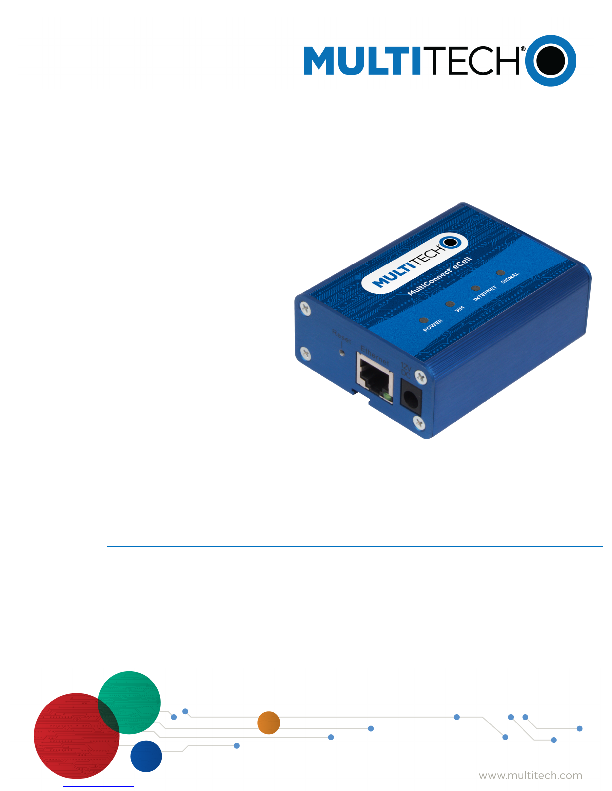
Product Overview
The Multiconnect eCell is an affordable 3G/4G Ethernet to Cellular Bridge used to enable devices with Internet
service. It is a simple alternative to complex and expensive cellular routers in applications where advanced
networking capabilities are already in place or are not required, but there is a need for remote access without
using local wired networks
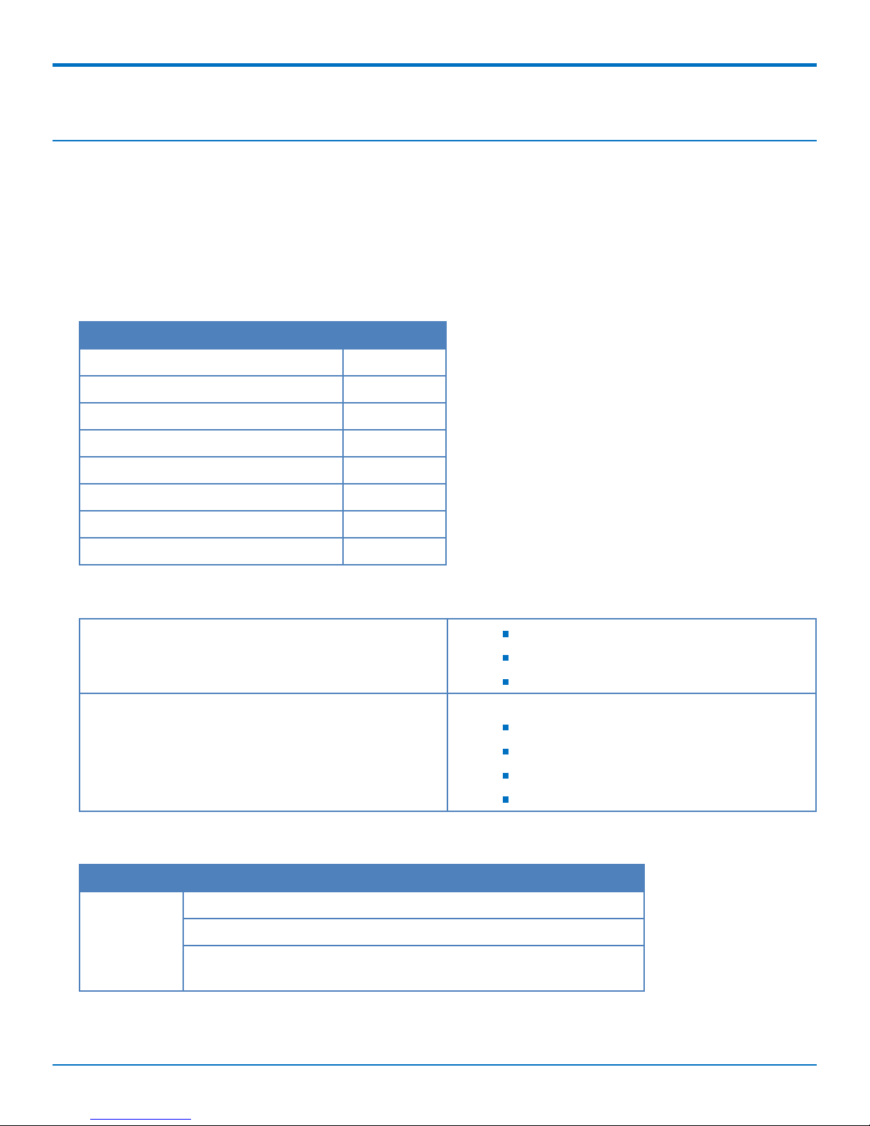
Package Contents
Description Quantity
MultiConnect eCell 1
Antenna 2
Mag Mount Adapter (EU SKU Only)
Power Adapter 1
WELCOME
Ethernet Cable 1
Four Rubber Feet 1
Mounting Stick 1
Quick Start 1
System Requirements
Network Requirements An external Ethernet device
3G/4G cellular service subscription
Ethernet connection
Configuration Requirements Browser Requirements
Internet Explorer 9.0 or higher
Chrome 2.0 or higher
Firefox 3.0 or higher
Safari 3.0 or higher
LED Indicators
Item Description
Power On: Solid when the device is in normal operational mode.
Off: No power.
Flashing: Device is in firmware upgrade mode, recovery mode,or
needs troubleshooting.
MultiConnect®eCell User Guide 5
Page 6
WELCOME
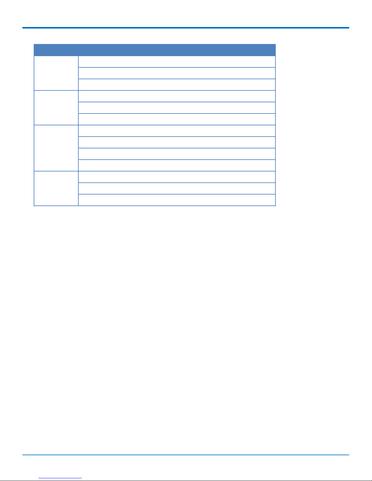
Item Description
SIM On: SIM card detected and ready.
Off: SIM card not present or not detected.
Flashing: Detecting and Querying SIM card information.
Internet On: 4G/3G is established and active.
Off: No active cellular connection.
Flashing: Active data transferred via cellular.
Signal On: Solid when there is a strong cellular signal.
Off: No cellular signal.
Flashing fast: Medium cellular signal.
Flashing slow: Weak cellular signal.
Ethernet (On
the Ethernet
port)
On: Solid when there is an Ethernet connection.
Off: No Ethernet connection.
Flashing: Data is actively transmitting via the Internet.
Using DeviceHQ for Device Management
DeviceHQ is a cloud-based device management tool for remote monitoring, upgrades, and configuration AEP
devices. For information on creating and using a DeviceHQ account, go to the
http://www.multitech.net/developer/software/devicehq/.
6 MultiConnect®eCell User Guide
Page 7
Chapter 2 – Specifications
MTE-LAT6-B07 and MTE-LEU6-B07
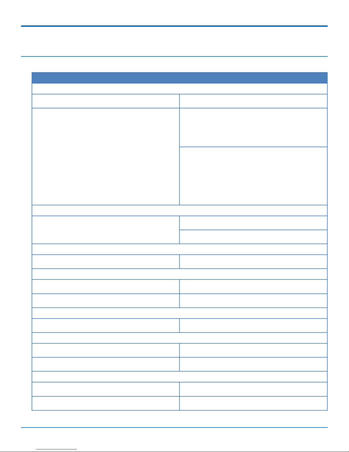
Category Description
General
SPECIFICATIONS
Performance
Frequency Bands
Radio
Cellular
4G LTE Speed
Packet Data
LTE , WCDMA, and GSM
SKU: MTE-LAT6-B07
LTE: FDD B2/B4/B12
WCDMA: B2/B4/B5
SKU: MTE-LEU6-B07
LTE: FDD B1/B3/B7/B8/B20/B28A, TDD
B38/B40/B41
WCDMA: B1/B8
GSM: B3/B8
MTE-LEU6-B07: 4G LTE Radio with 3G/2G fallback
MTE-LAT6-B07: 4G LTE Radio with 3G fallback
Up to 150 Mbps downlink/50 Mbps uplink
Connectors
Cellular
SIM Holder
Power Requirements
Voltage
Physical Description
Dimensions
Weight
Environment
Operating Temperature
Humidity
MultiConnect®eCell User Guide 7
Two female SMA connectors
Mini-SIM 2FF push push SIM
12 VDC @ 1A
3.2" x 2.5" x 1.2" (81.2 x 63.5 x 30.5 millimeters)
1.0 lbs. (0.45 Kg)
-10° C to +50° C
Relative humidity 10% to 93% non-condensing
Page 8
SPECIFICATIONS
Category Description
Certifications, Compliance, Warranty
CE Compliance (MTE-LEU6-B07)
FCC Compliance (MTE-LAT6-B07)
Network Compliance
Safety Compliance
Warranty
CE RED
FCC Part 15B, 22H, 24E, 27, and IC
PTCRB and AT&T
IEC 60950-1 2es Am2
IEC 62368-1
UL 60950-1 2ed
CAN/CSA-C22.2
RCM
Two years
8 MultiConnect®eCell User Guide
Page 9
INSTALLING AND USING THE ECELL
Chapter 3 – Installing and Using the eCell
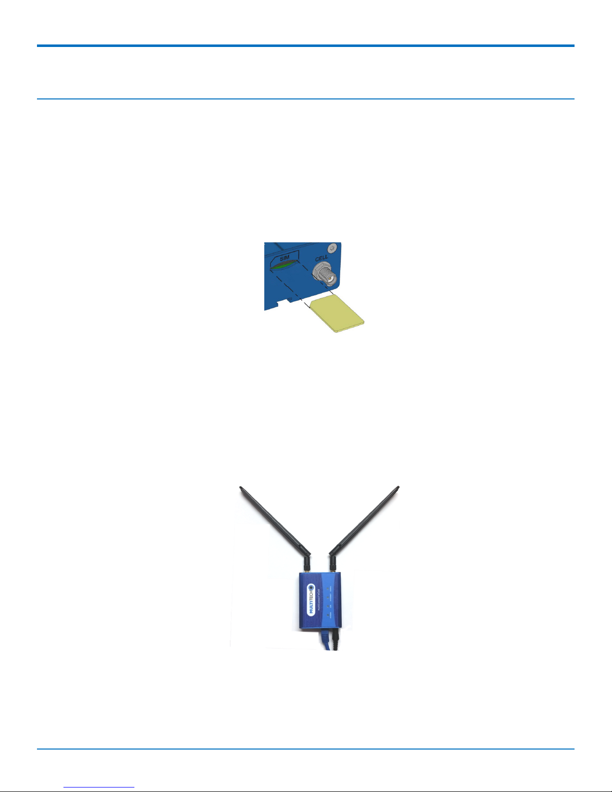
Installing the SIM Card
This device requires a SIM card, which is supplied by your service provider. Install the SIM card before connecting
antennas and cabling the device.
To install the SIM card:
1. Locate the SIM card slot on the side of the device. The slot is labeled SIM.
2. Slide the SIM card into the SIM card slot with the contact side facing down as shown. When the SIM card
is installed, it locks into place.
Attaching Antennas and Cables
Note: Before powering up the device, enable DHCP on your computer's Ethernet port.
1. Connect the provided antennas to the connectors labeled CELL and AUX. Finger tighten. For best cellular
performance, position the top of the antennas as far apart as possible.
2. Connect the Ethernet cable between the Ethernet ports on your computer and the device.
3. Connect the power adapter to the 12V DC connector.
4. To power up the device, plug the power adapter into an electrical outlet.
MultiConnect®eCell User Guide 9
Page 10

INSTALLING AND USING THE ECELL
Using the Setup Wizard
When using a 3G/4G network, verify a SIM card has been installed before powering on and starting setup.
Configure the device using the web UI. To access the web UI, enter the IP Address into your browser. The default
IP Address is 192.168.2.1. If this has been changed, type in the new IP Address.
From the menu on the left, click Wizard.
1. Wait for 60 seconds after connecting power. The computer gets IP address 192.168.2.100 via DHCP.
2. In a web browser, enter IP address 192.168.2.1.
3. Login using admin as both the Username and Password. If you are using the default password, it will
prompt you to change it for future logins.
4. Click Wizard on the left.
5. Click Next.
6. Change password, if desired and click Next. (Recommended)
7. Set the device's Time Zone and click Next.
8. Enter and configure APN.
a. Select Manual Configuration.
b. Set Country to Others.
c. Enter the APN provided by the SIM provider.
d. Click Next.
9. Click Apply.
10. Wait a few minutes and check LED status. Power, SIM, Internet, and Signal LEDs are on when there is a
live Internet connection. For more information on the LEDs, refer to LED Indicators.
After the device has a valid Internet connection, your computer automatically renews to the new IP address
assigned to cellular connection and have full access to the Internet.
10 MultiConnect®eCell User Guide
Page 11

Chapter 4 – Basic Network
WAN and Internet Setup for 3G/4G
This device has Cellular WAN interfaces, these can be configured individually to maximize Internet connection
setup.
To configure Cellular WAN settings go to Basic Network > WAN on the menu on the left.
1. Dial-up Profile: Use information given by your 3G/4G data services provider to setup your connection
including APN, dialed number, and account/password. Choose from Manual Configuration or Auto-
Detection. When selecting Manual Configuration, configure the following:
Country: Select the country. If using custom APN, select Others.
Service Provider: Select the service provider. If using custom APN, select Others.
APN: Verify predefined APN name or manually enter a custom APN name.
PIN code: If your card needs to be unlocked before making a data connection, enter the SIM card PIN
code.
Dial Number: Enter the ISP-provided dial number.
Account/Password: Enter the ISP-provided Account/Password.
Authentication: Choose Auto, PAP, or CHAP according to your ISP's authentication approach. If unsure,
choose Auto.
Primary/Secondary DNS: Enter the IP Address of the Domain Name Server. Most ISPs assign them
automatically.
2. Roaming: Allow internet connection when roaming.
3. Data Usage Monitor: Controls how much data is allowed for the 3G/4G connection during a defined cycle
period. This will help to avoid data overage charges from your Cellular service provider.
Carrier Name: Name of the carrier or provider.
Cycle Period: Cycle period duration in hours, weeks, or months.
Cycle Start Date: Cycle period start date and time.
Data Allowance: Set amount of data allowed during the cycle period.
Halting Internet: Stop internet connection when the maximum data allowance is reached during the cycle
period.
4. Connection Control: Setup WAN connection to be Always on, Connect-On-Demand, or Connect
Manually.
5. Time Schedule: Set the WAN connection to be active for a certain predefined period. Choose from
Always or By Schedule. If you choose By Schedule, add a new schedule at System > Scheduling.
6. MTU: Maximum Transmit Unit. Different WAN connections have different values. If unsure, use default
value of 0 (Auto).
7. IP Passthrough: This is a bridge mode between a LAN device and a WAN interface. For security, assign a
WAN interface IP Address to a fixed MAC address on the LAN device. In this mode, only one device is
allowed on the LAN.
Cellular Consecutive fails times: When the cellular connection cannot obtain an IP address
consecutive times, it will auto reboot the modem. Enter the number of allowed cellular IP address
failures before modem auto reboot.
BASIC NETWORK
MultiConnect®eCell User Guide 11
Page 12

BASIC NETWORK
8. NAT: Enable or disable the NAT mechanism between the LAN and WAN interfaces. The default is disable,
bridge mode only. In this mode, multiple LAN devices are supported.
Network Monitoring: Monitor the WAN interface connection status. Check Enable and the system
will monitor when there is no activity for a defined period of time, it will reset the cellular
connection.
Data Load Check: Enable this option if there are continuous incoming and outgoing data packets
passing through the WAN connection. If no data traffic is detected for the duration of the check
interval, it will disconnect and reconnect the cellular WAN connection.
Check Interval: Indicate how often to check the data traffic on the WAN connection.
Cellular Consecutive fails times: When the cellular connection cannot obtain an IP address
consecutive times, it will auto reboot the modem. Enter the number of allowed cellular IP address
failures before modem auto reboot.
Network Monitoring (keep alive): Monitor cellular connection status. As a result, the system can
prevent the embedded 3G/LTE modem from auto-timeout and disconnects after a period of
inactivity. Check Enable.
DNS Query or ICMP Checking: Perform DNS query or ICMP on the cellular connection to
determine an active cellular connection is still valid.
Data Load Check: Enable this option if there are continuous incoming and outgoing data packets
passing through the WAN connection. If no data traffic is detected for the duration of the check
interval, it will disconnect and reconnect the cellular WAN connection.
Check Interval: Indicate how often to perform DNS query or ICMP check on the WAN connection.
Target 1/Target2: Set host for network monitoring keep alive check including DNS1, DNS2, or
Other host (input IP address manually).
Ethernet LAN
This device has one Ethernet LAN port to connect to one external Ethernet device. To configure, on the menu on
the left go to Basic Network > LAN.
1. Site Name: Enter the Site name to identify the location when setting up DeviceHQ.
2. LAN IP Address: Enter the LAN's IP address. This IP address must be used as the computer's default
gateway. This is also the IP address of the web UI. If you change this, type in the new IP address into a
web browser to see the web UI.
3. Subnet Mask: Enter the LAN's subnet mask. This defines how many clients are allowed in one network or
subnet. The default subnet is 255.255.255.0 and allows for a maximum of 254 IP addresses.
NAT
This option will appear when NAT mode is selected in the WAN internet setup page. This mode allows multiple LAN
devices to share one cellular WAN connection.
1. Configuration: Check option for NAT loopback. Allows you to access the WAN IP address from inside your
LAN network.
2. Virtual Server: Allows you to setup the WAN IP to LAN IP mapping in order for remote access to LAN
devices.
a. Public Port: Enter the public IP port number.
b. Server IP: Enter the LAN device IP address.
12 MultiConnect®eCell User Guide
Page 13

BASIC NETWORK
c. Private Port: Enter the LAN device IP port number.
d. Protocol: Select TCP or UDP or both.
e. Time Schedule: Select a time schedule when this rule will be affective.
f. Rule: Check to enable the rule.
3. DMZ (Demilitarized Zone) Host: This is a host without the protection of a firewall. It allows a computer to
be exposed to unrestricted 2-way communication from the Internet. If a specific application is blocked by
NAT mechanism, you can designate that LAN computer as a DMZ host to solve this problem.
Note: This feature should only be used when necessary.
Text of second paragraph.
Routing
if there is more than one router and subnet, enable the routing function to allow packets to find proper routing
paths and allow different subnets to communicate with each other.
Static Routing
For static routing, you can specify up to 16 routing rules. These rules allow you to determine which physical
interface addresses are being utilized for outgoing data. For each rule, enter the destination IP address, subnet
mask, gateway, and hop. Check Enable or Disable.
Dynamic DNS
To host a server on a changing IP address, you have to use dynamic domain name service (DDNS). DDNS maps the
name of your host to the current IP address, which changes each time you connect to your ISP. Before you enable
DDNS, you need to register an account on one of the DDNS servers in the provider list. To configure, from the
menu on the left choose Basic Network > Client/Server.
1. DDNS: Check Enable.
2. Provider: The DDNS provider supports a service to bind your IP with a certain domain name.
3. Host Name: Register a domain name to the DDNS provider.
4. Username/email: Enter a username or email based on the DDNS provider requirements.
5. Password/Key: Enter a password or key based on the DDNS provider requirements.
DHCP Server
The gateway supports DHCP server to serve the DHCP requests from a LAN device. There is one default LAN IP
address that is the same as the gateway LAN interface. The subnet mask is 255.255.255.0, and the IP Pool ranges
from .100 to .200 as shown on the following DHCP Server List. To edit one DHCP server configurations, click Edit at
the end of the DHCP server information.
There is one additional option to show the DHCP client list and IP addresses of local client hosts.
To configure, from the menu on the left choose Basic Network > Client/Server.
1. DHCP Server Name: Name of the DHCP server. This is optional.
2. LAN IP Address: Specify the local IP address of the enabled DHCP Server. This is the LAN IP address of this
gateway for the DHCP server. Normally, this IP address will be also the default gateway of local
computers and devices.
MultiConnect®eCell User Guide 13
Page 14

BASIC NETWORK
3. Subnet Mask: Select the subnet mask for the DHCP server. The subnet mask defines how many clients are
allowed in one network or subnet. The default subnet mask is 255.255.255.0/24. This means that a
maximum of 254 IP addresses are allowed in the subnet. However, one of them is occupied by the LAN IP
of the gateway.
4. IP Pool Starting/Ending Address: Specify the starting/ending address of the IP address pool. When there
is a request, the DHCP server will automatically allocate an unused IP address from the IP address pool to
the requesting computer.
Note: The number of IP addresses in this IP pool must be less than the maximum number of subnet
networks according to the set subnet mask.
5. Lease Time: DHCP lease time to the DHCP client.
6. Domain Name: This information is passed to the clients. This is optional.
7. Primary DNS/Secondary DNS: Assign DNS Servers. This is optional.
8. Primary WINS/Secondary WINS: Assign WINS Servers. This is optional.
9. Gateway: This is the alternate Gateway IP address. Assign another gateway to your computer when the
DHCP server offers an IP address. For example, the gateway will assign an IP address to local computers
but they will access the Internet through another gateway. This is optional.
10. Server: Check Enable if you want the DHCP server active.
System Management (DeviceHQ)
Sign up with DeviceHQ and Setup MTE to communicate with Device HQ
1. Register and sign up a new account at https://www.devicehq.com.
2. Login to https://www.devicehq.com and generate a device API key using the following steps:
a. Select Account info (to the right of the account email address) and click Edit.
b. Check Device API Enabled and click Update Account.
c. Click on Generate new Device API Keys.
d. Write down and save "Device API Secret" and "Device API Auth Token", these two keys are required
during MTE device setup.
Note: DO NOT lose these keys since there is no way to see them again.
MTE UI Setup for DeviceHQ
MTE must be running firmware version 2.04 or above in order to have DeviceHQ support. Download firmware from
the website and upgrade the device before proceeding. https://www.multitech.com/models/92506980LF
1. In Basic Network, on the LAN Setup Screen: Enter and Define Site Name so it shows as Description in
DeviceHQ
2. In Basic Network, on the System Management Setup Screen: DeviceHQ access setup requires:
a. Check the Enable option.
b. Enter DeviceHQ account API secret and API Auth Token.
c. Click Save.
Setup New Firmware File on DeviceHq
This is performed after logging in to DeviceHQ.
1. Click on the Files tab and click the New Firmware button.
2. Select model = Unspecified
14 MultiConnect®eCell User Guide
Page 15

3. Enter the name and version number of the firmware file.
4. Choose the firmware BIN file.
5. Click the Upload button.
6. Check and make sure MD5 checksum matches on the firmware BIN file.
Push a Firmware Update to all Devices
This is performed after logging in to DeviceHQ.
1. Check all the devices.
2. Click on tasks and select Upgrade Firmware.
3. Select the firmware file you want to push to the devices.
4. Click OK.
This will schedule a new firmware push to all devices the next time they check in.
Push a Firmware Update to One Device
This is performed after logging in to DeviceHQ.
1. Click on the individual device to view more details.
2. Click on Schedule, select Upgrade Firmware, and select the firmware file.
3. Click OK when prompted in the message window.
BASIC NETWORK
Setup a Configuration File on DeviceHQ
This is performed after logging in to DeviceHQ.
1. Click on the Files tab.
2. Click on New Configuration.
3. Enter the name and description of the configuration file.
4. Choose the configuration ZIP file (zip up the configuration BIN file into a .zip file).
5. Click Upload.
Note: MTE configuration BIN files must be created using an external device and saved as backup, then the
BIN file must be a .zip file when uploaded to DeviceHQ. Name the ZIP file based on device description or
serial number so it can be easily identified.
Push a Configuration File to a Single Device
1. Click on the individual device to view more details.
2. Click on Schedule, select Upgrade Config, and select the config file.
3. Click OK when prompted in the message window.
Requesting Device Log Files
1. Click on the individual device to view more details.
2. Click on Schedule and select Request Device Logs.
3. Click OK when prompted in the message window.
Requesting a Device Reboot
1. Click on the individual device to view more details.
2. Click on Schedule and select Reboot.
MultiConnect®eCell User Guide 15
Page 16

BASIC NETWORK
3. Click OK when prompted in the message window.
MTE Data Usage with DeviceHQ
Each time a device checks in it can take up to 23 kb.
Log file upload can vary depending on the size of the log files.
Configuration file size can be up to 12 kb.
MTE firmware file size is approximately 9 mb.
16 MultiConnect®eCell User Guide
Page 17

ADVANCED NETWORK
Chapter 5 – Advanced Network
Advanced Network
This section is only available when NAT mode is selected in the WAN cellular internet setup. Enable/disable
firewall, Stealth Mode, SPI, and Discard PING from the WAN interface.
Configuration
Firewall: Enable / Disable Firewall.
Options
Stealth Mode: When enabled, the router will not respond to port scans from the WAN. This makes the
router less susceptible to discovery and attacks.
SPI (Stateful Packet Inspection): Also known as dynamic packet filtering. This helps to prevent cyber attacks
by tracking more states per session. It validates that the traffic passing through that session conforms to the
protocol.
Discard PING from WAN side: When enabled, this gateway won't reply to any ICMP request packets from
the WAN side.
MultiConnect®eCell User Guide 17
Page 18

SYSTEM
Chapter 6 – System
System
This section includes system information, system logs, system tools (i.e. firmware updates), scheduling, and
external syslog server setup.
Change Password
1. Old, New, and Confirmation Password: To change your password, type in your old password, then enter
in the new password in the new password and confirm password fields. Click Save to store your settings
or Undo to cancel the changes.
2. Administrator Time-out: Other options allow you to set when there are no activities on the web user
interface.
3. Telnet with CLI: Check to Enable CLI access via LAN or WAN.
4. Connection Type: Check to Enable Telnet or SSH access via LAN or WAN. The Telnet and SSH access IP
port number can be configured to use custom port.
5. Options: Setup local or remote HTTP or HTTPS web UI access. Enter unique remote IP address and subnet
mask to restrict remote web UI access. Enable web UI access for LANandd/or WAN interfaces.
System Information
This section displays System Information for the WAN interface and the current date and time.
System Status
System Status displays and captures log information. It also allows log files to be sent to an external syslog server.
1. Web Log: Check Enable for System, Attacks, Drop, and Debug categories, then click Save. Click View to
display or download log files.
2. Syslogd: Check to Enable logging to an external syslog server. The external syslog server's IP address can
be configured using the External Servers option.
System Tools
Options to setup system time, perform firmware updates, ping test, trace route test, reboot or schedule a reboot,
reset to factory defaults, wake up on LAN, and backup configuration settings.
System Time: Configure the time zone. You can select sync current time and date with external time server
or local PC time.
Firmware Upgrade/Configuration Restore: Perform firmware upgrade or restore a backup configuration
file.
Note: To check the current firmware version, refer to the top of the page after login.
Reboot: Select reboot now or set a schedule for an auto-reboot to occur.
Reset to Default: Reset all settings back to factory defaults.
Backup/Restore Configuration Settings: Save all current settings to a configuration file or restore a backup
configuration file.
18 MultiConnect®eCell User Guide
Page 19

Scheduling
1. Enable the schedule function and setup a rule for each schedule. The rule can be used in many other
functions, such as scheduling an auto-reboot, scheduling an auto WAN connectivity, etc.
2. Click Save to store all schedule settings.
External Servers
1. Click Add to add and configure an external syslog server. The server will allow logging to be captured via
an external syslog server.
2. Click Save to save all the server settings.
SYSTEM
MultiConnect®eCell User Guide 19
Page 20

SAFETY WARNINGS
Chapter 7 – Safety Warnings
Ethernet Ports
CAUTION: Ethernet ports and command ports are not designed to be connected to a public telecommunication
network.
Radio Frequency (RF) Safety
Due to the possibility of radio frequency (RF) interference, it is important that you follow any special regulations
regarding the use of radio equipment. Follow the safety advice given below.
Operating your device close to other electronic equipment may cause interference if the equipment is
inadequately protected. Observe any warning signs and manufacturers’ recommendations.
Different industries and businesses restrict the use of cellular devices. Respect restrictions on the use of
radio equipment in fuel depots, chemical plants, or where blasting operations are in process. Follow
restrictions for any environment where you operate the device.
Do not place the antenna outdoors.
Switch OFF your wireless device when in an aircraft. Using portable electronic devices in an aircraft may
endanger aircraft operation, disrupt the cellular network, and is illegal. Failing to observe this restriction
may lead to suspension or denial of cellular services to the offender, legal action, or both.
Switch OFF your wireless device when around gasoline or diesel-fuel pumps and before filling your vehicle
with fuel.
Switch OFF your wireless device in hospitals and any other place where medical equipment may be in use.
Interference with Pacemakers and Other Medical Devices
Potential interference
Radio frequency energy (RF) from cellular devices can interact with some electronic devices. This is
electromagnetic interference (EMI). The FDA helped develop a detailed test method to measure EMI of implanted
cardiac pacemakers and defibrillators from cellular devices. This test method is part of the Association for the
Advancement of Medical Instrumentation (AAMI) standard. This standard allows manufacturers to ensure that
cardiac pacemakers and defibrillators are safe from cellular device EMI.
The FDA continues to monitor cellular devices for interactions with other medical devices. If harmful interference
occurs, the FDA will assess the interference and work to resolve the problem.
Precautions for pacemaker wearers
If EMI occurs, it could affect a pacemaker in one of three ways:
Stop the pacemaker from delivering the stimulating pulses that regulate the heart's rhythm.
Cause the pacemaker to deliver the pulses irregularly.
Cause the pacemaker to ignore the heart's own rhythm and deliver pulses at a fixed rate.
Based on current research, cellular devices do not pose a significant health problem for most pacemaker wearers.
However, people with pacemakers may want to take simple precautions to be sure that their device doesn't cause
a problem.
20 MultiConnect®eCell User Guide
Page 21

SAFETY WARNINGS
Keep the device on the opposite side of the body from the pacemaker to add extra distance between the
pacemaker and the device.
Avoid placing a turned-on device next to the pacemaker (for example, don’t carry the device in a shirt or
jacket pocket directly over the pacemaker).
MultiConnect®eCell User Guide 21
Page 22

47 CFR PART 15 REGULATION CLASS B DEVICES
Chapter 8 – 47 CFR Part 15 Regulation Class B Devices
This equipment has been tested and found to comply with the limits for a Class B digital device, pursuant to part
15 of the FCC Rules. These limits are designed to provide reasonable protection against harmful interference in a
residential installation. This equipment generates, uses, and can radiate radio frequency energy and, if not installed
and used in accordance with the instructions, may cause harmful interference to radio communications. However,
there is no guarantee that interference will not occur in a particular installation. If this equipment does cause
harmful interference to radio or television reception, which can be determined by turning the equipment off and
on, the user is encouraged to try to correct the interference by one or more of the following measures:
Reorient or relocate the receiving antenna.
Increase the separation between the equipment and receiver.
Connect the equipment into an outlet on a circuit different from that to which the receiver is connected.
Consult the dealer or an experienced radio/TV technician for help.
Warning: Changes or modifications to this unit not expressly approved by the party responsible for compliance
could void the user’s authority to operate the equipment.
FCC Interference Notice
This device complies with part 15 of the FCC Rules. Operation is subject to the following two conditions:
1. This device may not cause harmful interference, and
2. This device must accept any interference received, including interference that may cause undesired
operation.
22 MultiConnect®eCell User Guide
Page 23

INDUSTRY CANADA CLASS B NOTICE
Chapter 9 – Industry Canada Class B Notice
This Class B digital apparatus meets all requirements of the Canadian Interference-Causing Equipment Regulations.
Cet appareil numérique de la classe B respecte toutes les exigences du Reglement Canadien sur le matériel
brouilleur.
This device complies with Industry Canada license-exempt RSS standard(s). The operation is permitted for the
following two conditions:
1. the device may not cause interference, and
2. this device must accept any interference, including interference that may cause undesired operation of
the device.
Le présent appareil est conforme aux CNR d'Industrie Canada applicables aux appareils radio exempts de licence.
L'exploitation est autorisée aux deux conditions suivantes:
1. l'appareil ne doit pas produire de brouillage, et
2. l’appareil doit accepter tout brouillage radioélectrique subi, même si le brouillage est susceptible d’en
compromettre le fonctionnement.
Industry Canada
Le présent appareil est conforme aux CNR d'Industrie Canada applicables aux appareils radio exempts de licence.
L'exploitation est autorisée aux deux conditions suivantes:
1. l'appareil ne doit pas produire de brouillage, et
2. l'utilisateur de l'appareil doit accepter tout brouillage radioélectrique subi, même si le brouillage est
susceptible d'en compromettre le fonctionnement.
MultiConnect®eCell User Guide 23
Page 24

RESTRICTION OF THE USE OF HAZARDOUS SUBSTANCES (ROHS)
Chapter 10 – Restriction of the Use of Hazardous
Substances (RoHS)
Multi-Tech Systems, Inc.
Certificate of Compliance
2011/65/EU
Multi-Tech Systems, Inc. confirms that its embedded products comply with the chemical concentration limitations
set forth in the directive 2011/65/EU of the European Parliament (Restriction of the use of certain Hazardous
Substances in electrical and electronic equipment - RoHS).
These MultiTech products do not contain the following banned chemicals1:
Lead, [Pb] < 1000 PPM
Mercury, [Hg] < 1000 PPM
Hexavalent Chromium, [Cr+6] < 1000 PPM
Cadmium, [Cd] < 100 PPM
Polybrominated Biphenyl, [PBB] < 1000 PPM
Polybrominated Diphenyl Ether, [PBDE] < 1000 PPM
Environmental considerations:
Moisture Sensitivity Level (MSL) =1
Maximum Soldering temperature = 260C (in SMT reflow oven)
1
Lead usage in some components is exempted by the following RoHS annex, therefore higher lead concentration
would be found in some modules (>1000 PPM);
- Resistors containing lead in a glass or ceramic matrix compound.
24 MultiConnect®eCell User Guide
Page 25

WASTE ELECTRICAL AND ELECTRONIC EQUIPMENT STATEMENT
Chapter 11 – Waste Electrical and Electronic
Equipment Statement
Note: This statement may be used in documentation for your final product applications.
WEEE Directive
The WEEE Directive places an obligation on EU-based manufacturers, distributors, retailers, and importers to takeback electronics products at the end of their useful life. A sister directive, ROHS (Restriction of Hazardous
Substances) complements the WEEE Directive by banning the presence of specific hazardous substances in the
products at the design phase. The WEEE Directive covers all MultiTech products imported into the EU as of August
13, 2005. EU-based manufacturers, distributors, retailers and importers are obliged to finance the costs of recovery
from municipal collection points, reuse, and recycling of specified percentages per the WEEE requirements.
Instructions for Disposal of WEEE by Users in the European Union
The symbol shown below is on the product or on its packaging, which indicates that this product must not be
disposed of with other waste. Instead, it is the user's responsibility to dispose of their waste equipment by handing
it over to a designated collection point for the recycling of waste electrical and electronic equipment. The separate
collection and recycling of your waste equipment at the time of disposal will help to conserve natural resources
and ensure that it is recycled in a manner that protects human health and the environment. For more information
about where you can drop off your waste equipment for recycling, please contact your local city office, your
household waste disposal service or where you purchased the product.
July, 2005
MultiConnect®eCell User Guide 25
Page 26

PTCRB REQUIREMENTS
Chapter 12 – PTCRB Requirements
There cannot be any alteration to the authorized antenna system. The antenna system must be the same type with
similar in-band and out-of-band radiation patterns and maintain the same specifications.
26 MultiConnect®eCell User Guide
Page 27

EMC, SAFETY, AND RADIO EQUIPMENT DIRECTIVE (RED) COMPLIANCE
Chapter 13 – EMC, Safety, and Radio Equipment
Directive (RED) Compliance
The CE mark is affixed to this product to confirm compliance with the following European Community Directives:
Council Directive 2011/65/EU on the restriction of the use of certain hazardous substances in electrical
and electronic equipment;
and
Council Directive 2014/53/EU on radio equipment and telecommunications terminal equipment and the
mutual recognition of their conformity.
MultiTech declares that this device is in compliance with the essential requirements and other relevant provisions
of Directive 2014/53/EU. The declaration of conformity may be requested at https://support.multitech.com.
MultiConnect®eCell User Guide 27
 Loading...